


UM1A
Installation and Operation Manual

UM1A
CONTENTS
Warnings and Compliance .................................................................................................. |
1 |
. |
Introduction......................................................................................................................... |
2 |
|
Safety Information............................................................................................................... |
3 |
|
Installation .......................................................................................................................... |
4 |
|
Wiring ................................................................................................................................. |
6 |
|
Basic Operation .................................................................................................................. |
8 |
|
Tuner Operation................................................................................................................ |
10 |
|
Weather Band Operation .................................................................................................. |
12 |
|
Weatherband Frequencies ................................................................................................ |
12 |
|
SiriusXM® Radio Operation ............................................................................................... |
13 |
|
USB MP3 Operation ......................................................................................................... |
18 |
|
Bluetooth Operation .......................................................................................................... |
19 |
|
APP Operation.................................................................................................................. |
20 |
|
Specifications.................................................................................................................... |
21 |
|
Troubleshooting ................................................................................................................ |
21 |
|
www.asaelectronics.com
877.305.0445
ii

UM1A
WARNINGS AND COMPLIANCE
WARNING! To reduce the risk of fire of electric shock, do not expose this apparatus to rain or moisture.
WARNING! The apparatus shall not be exposed to dripping or splashing and that no objects filled with liquids, such as vases, shall be placed on apparatus.
FCC Notes
WARNING! Changes or modifications to this unit not expressly approved by the party responsible for compliance could void the user’s authority to operate the equipment.
NOTE: This equipment has been tested and found to comply with the limits for a Class B digital device, pursuant to Part 15 of the FCC rules. These limits are designed to provide reasonable protection against harmful interference in a residential installation.
This equipment generates, uses, and can radiate radio frequency energy and, if not installed and used in accordance with the instructions, may cause harmful interference to radio communications.
However, there is no guarantee that interference will not occur in a particular installation. If this equipment does cause harmful interference to radio or television reception, which can be determined by turning the equipment off and on, the user is encouraged to try to correct the interference by one or more of the following measures:
Reorient or relocate the receiving antenna.
Increase the separation between the equipment and receiver.
Connect the equipment into an outlet on a circuit different from that to which the receiver is connected.
Consult the dealer or an experienced radio/TV technician for help.
1
UM1A
INTRODUCTION |
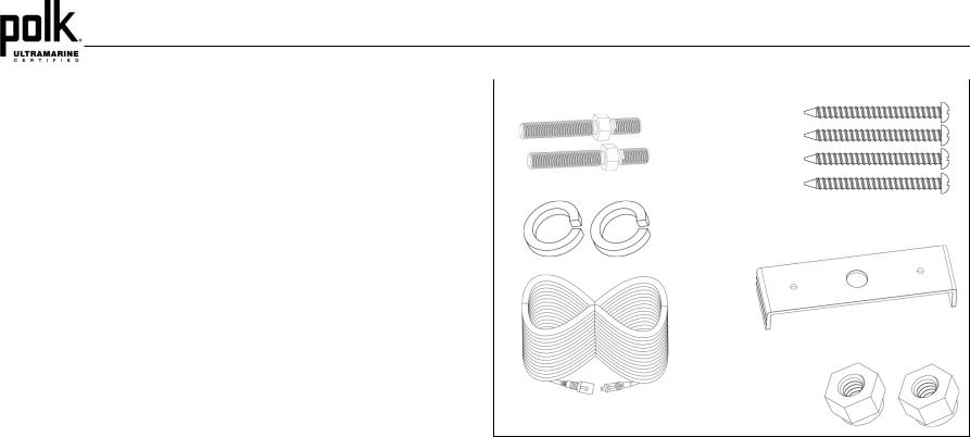
HARDWARE KIT CONTENTS |
System Features |
Mounting |
Screws x 4 |
|
Features of the Polk UM1A marine audio system include: |
|
Full Dot Matrix LCD |
Bolt x 2 |
AM/FM US/EURO Tuner with 30 Presents (12 AM, 18 FM)
SiriusXM-Ready™
|
USB Playback of MP3 and WMA files (USB1 & USB2) |
Spring Washer x 2 |
|
|
Bluetooth (Supports A2DP & AVRCP)
Weatherband Tuner with Alerts
Mute
Pre-set Equalizer – 5 settings (User, Flat, Pop, Classical, Rock)
Electronic Bass, Mid Treble, Balance and Fader Sub Controls
|
Output Power 50W x 4 |
Rear Mounting |
|
Protective Commander Cover |
Bracket |
Wired Remote Control Ready (optional PRC100BC, PRC200BC)
Zone Control Expansion Ready (optional UMZC4A)
4-Channel Pre-amp Line Level Outputs (Front & Rear RCA)
|
1-Channel Subwoofer-Outputs (RCA) |
Connector Assembly 4 pin Cable |
Lock Nut x 2 |
|
Auxiliary Audio Input (RCA AUX1 & AUX2)
Public Announcement (PA) Feature with Optional Microphone (sold separately)
Content List
Polk UM1A Tuner/Amp Module
Polk UM1A Wired Commander
10’ Extension Cable
Commander Cover
Quick Reference Guide
Cutout Mounting Template
Hardware Kit
-Rear Mounting Bracket
-(4x) #8 Mounting Screws
-(2x) Mounting Bolt
-(2x) Lock Washer
-(2x) Lock Nut
2

UM1A
SAFETY INFORMATION
When Boating
Keep the volume level low enough to be aware of your surroundings.
Protect from Water
Do not submerge the product in water, as this can cause electric shorts, fire or other damage.
Protect from the Elements
Use the included cover to protect the wired commander from sunlight, dust, and water while not in use.
Protect from High Temperatures
Do not mount radio in close proximity to engine compartment.
Use the Proper Power Supply
This product is designed to operate with a 12 volt DC negative ground battery system.
CAUTION:
DO NOT OPEN COVERS AND DO NOT REPAIR BY YOURSELF. PLEASE REFER
SERVICING TO A QUALIFIED TECHNICIAN.
WARNING:
TO REDUCE THE RISK OF FIRE OR ELECTRIC SHOCK AND INTERFERENCE, USE
ONLY THE RECOMMENDED ACCESSORIES.
3
UM1A
INSTALLATION
Before You Begin
Always disconnect the negative battery terminal
Important Notes
Before final installation, test the wiring connections to make sure the unit is connected properly and the system works.
Consult with your nearest dealer if installation requires the drilling of holes or other modifications to your vessel.
Install the unit where it does not interfere with operating the vessel and cannot injure passengers.
Use the included template to cut the installation opening.
Commander Cover
During storage, use the included cover to prolong the life of your device by protecting the wired commander from direct sunlight, moisture, dust, and other elements.
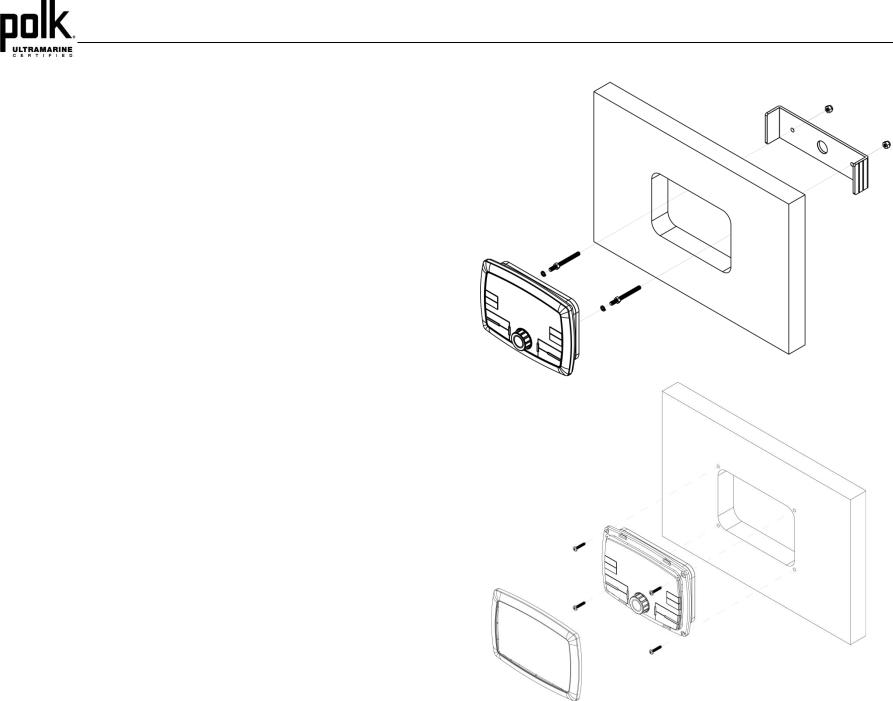
Wired Commander Mounting
Choose a mounting area for the wired commander that is clean and flat, allowing the rear gasket to fully seal to the mounting surface.
Secure the wired commander using either of the recommended mounting methods detailed below.
Bracket Mount
Insert wired commander through cut-out and secure with bracket using included hardware as detailed in the diagram.
Screw Mount
Secure the wired commander to the mounting surface using #6 stainless steel pan head screws (not included) as detailed in the diagram.
Bracket Mount
Screw Mount
4
|
|
|
UM1A |
|
|
|
|
|
|
Removing the Unit |
3. |
Route the tuner/amplifier harness and cable throughout the vessel as required. Keep |
||
|
some slack in the harness/cables so it won't be too tight, as this can cause damage to |
|||
|
|
|
||
To remove the commander, remove bracket mount or remove trim ring and mounting screws, |
|
the wires. |
||
then slide wired commander out of the mounting hole. |
4. |
Follow the wiring diagram carefully and make certain all connections are secured with |
||
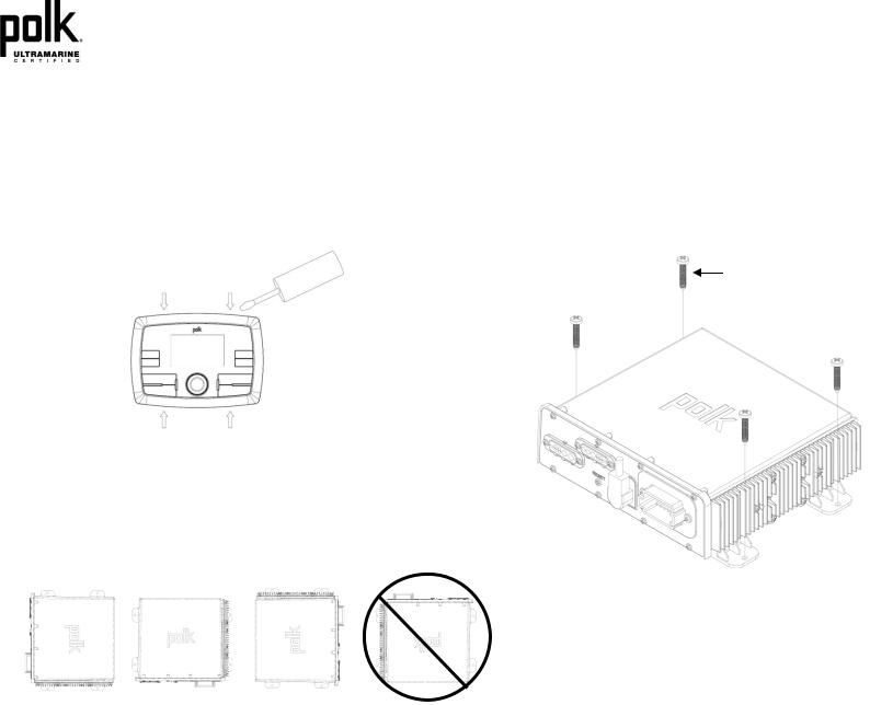
Removing the Trim Ring (Screw Mount Only) |
|
insulated crimp connectors to ensure proper operation. |
||
5. |
After completing the wiring connections, reconnect the negative terminal on the battery |
|||
Before removing the mounting screws, remove the trim ring first. Using a small non-metallic |
and turn the unit on to confirm operation (vessel accessory switch must be on). If the |
|
|
|
|
panel removal tool, apply the flat edge of the tool to the trim ring top latch area (as shown). |
unit does not operate, disconnect battery, recheck all wiring and refer to the |
|
|
|
|
Pull forward and twist to disengage the latches. Note: Use a protective surface under the |
trouble-shooting guide located in the back of the manual. |
|
|
|
|
removal tool so as not to damage the mounting surface. |
|
|
|
STAINLESS STEEL #8 SCREWS (INCLUDED) |
|
|
|
|
|
|
1/8” PILOT HOLES FOR SUPPLIED SELF-STARTING SCRWS |
|
|
0.180 PILOT HOLES WHEN USING THREADED MACHINE SCREWS |
|
|
|
Tuner / Amplifier Module Mounting
1.Choose a mounting area for the tuner/amplifier module that will provide plenty of ventilation to prevent the amplifier from overheating. The tuner/amplifier module can be mounted in the horizontal or vertical position. Please note that when mounting in vertical position, do not mount with the harness exit points facing straight up, as water can collect around the chassis in these areas.
2.Using the shortest length of the recommended size screws possible, mount the tuner/ amplifier as detailed in the diagram on the right.
5

WIRING
UM1A
PIN |
DESCRIPTION |
PIN |
|
DESCRIPTION |
|||
1 |
SPEAKER RR– |
7 |
|
|
SWITCHED +12VDC |
||
2 |
SPEAKER RR+ |
8 |
|
|
GROUND |
||
3 |
SPEAKER FL+ |
9 |
|
|
ILL-DIM (RUNNING LIGHTS) |
||
4 |
SPEAKER FL– |
10 |
|
REMOTE TRIGGER |
|||
5 |
SPEAKER FR+ |
11 |
|
SPEAKER RL+ |
|||
6 |
SPEAKER FR– |
12 |
|
SPEAKER RL– |
|||
|
|
|
|
|
|||
PIN NO. |
WIRE COLOR |
|
DESCRIPTION |
|
|||
1 |
|
RED |
|
|
+12VDC |
|
|
2 |
|
BLUE |
|
|
DATA |
|
|
3 |
|
WHITE |
|
|
LEFT AUDIO OUT |
|
|
4 |
|
YELLOW |
|
|
RIGHT AUDIO OUT |
|
|
5 |
|
EMPTY |
|
|
NO CONNECTION |
|
|
6 |
|
GREEN |
|
|
NO CONNECTION |
|
|
7 |
|
GRAY |
|
|
NO CONNECTION |
|
|
8 |
|
BLACK |
|
|
AUDIO GROUND |
|
|
9 |
|
SHELL |
|
|
GROUND |
|
|
WARNING: Wiring harnesses come with stripped and tinned leads to aid in the installation process. Any unused speaker wires must have their exposed ends cut off or insulated individually.
6
 Loading...