


PA450UM
Installation and Operation Manual

PA450UM
Contents
Warnings and Compliance |
......................................................................1 |
Introduction .............................................................................................. |
3 |
Safety Information.................................................................................... |
4 |
Installation ................................................................................................ |
5 |
Wiring ........................................................................................................ |
7 |
Remote Control Options.......................................................................... |
8 |
Basic Operation........................................................................................ |
9 |
Tuner Operation...................................................................................... |
11 |
Weather Band Operation ....................................................................... |
13 |
SiriusXM Operation ................................................................................ |
14 |
USB MP3 Operation ............................................................................... |
19 |
iPod Operation........................................................................................ |
21 |
Accessing iPod Mode ............................................................................ |
21 |
Bluetooth Operation............................................................................... |
22 |
Specifications ......................................................................................... |
24 |
Troubleshooting ..................................................................................... |
24 |
Copyrights and Trademarks
iPhone, iPod, iPod classic, iPod nano, iPod shuffle, and iPod touch are trademarks of Apple Inc., registered in the U.S. and other countries.
“Made for iPod” and “Made for iPhone” mean that an electronic accessory has been designed to connect specifically to iPod or iPhone respectively, and has been certified by the developer to meet Apple performance standards. Apple is not responsible for the operation of this device or its compliance with safety and regulatory standards. Please note that the use of this accessory with iPod or iPhone may affect wireless performance.
Sirius, XM and all related marks and logos are trademarks of SiriusXM Radio, Inc. and its subsidiaries. All rights reserved.
www.asaelectronics.com
877.305.0445
ii

PA450UM
WARNINGS AND COMPLIANCE
Important Safety Instructions
1.Read these instructions.
2.Keep these instructions.
3.Heed all warnings.
4.Follow all instructions.
5.Do not use this apparatus near water.
6.Clean only with a dry cloth.
7.Do not block any ventilation openings. Install in accordance with the manufacturer's instructions.
8.Do not install near any heat sources such as radiators, heat registers, stoves, or other apparatus (including amplifiers) that produce heat.
9.Do not defeat the safety purpose of the polarized or grounding-type plug. A polarized plug has two blades with one wider than the other. A grounding type plug has two blades and a third grounding prong. The wide blade or the third prong is provided for your safety.
When the provided plug does not fit into your outlet, consult an electrician for replacement of the obsolete outlet.
10.Protect the power cord from being walked on or pinched particularly at plugs, convenience receptacles, and the point where they exit from the apparatus.
11.Only use attachments/accessories specified by the manufacturer.
12.Use only with a cart, stand, tripod, bracket, or table specified by the manufacturer, or sold with the apparatus. When a cart is used, use caution when moving the cart/apparatus combination to avoid injury from tip-over.
Portable Cart Warning
13.Unplug this apparatus during lightning storms or when unused for long periods of time.
14.Refer all servicing to qualified service personnel. Servicing is required when the apparatus has been damaged in any way, such as power -supply cord or plug is damaged, liquid has been spilled or objects have fallen into the apparatus, the apparatus has been exposed to rain or moisture, does not operate normally, or has been dropped.
WARNING! To reduce the risk of fire of electric shock, do not expose this apparatus to rain or moisture.
WARNING! The apparatus shall not be exposed to dripping or splashing and that no objects filled with liquids, such as vases, shall be placed on apparatus.
1

PA450UM
FCC Notes
WARNING! Changes or modifications to this unit not expressly approved by the party responsible for compliance could void the user’s authority to operate the equipment.
NOTE: This equipment has been tested and found to comply with the limits for a Class B digital device, pursuant to Part 15 of the FCC rules. These limits are designed to provide reasonable protection against harmful interference in a residential installation.
This equipment generates, uses, and can radiate radio frequency energy and, if not installed and used in accordance with the instructions, may cause harmful interference to radio communications.
However, there is no guarantee that interference will not occur in a particular installation. If this equipment does cause harmful interference to radio or television reception, which can be determined by turning the equipment off and on, the user is encouraged to try to correct the interference by one or more of the following measures:
•Reorient or relocate the receiving antenna.
•Increase the separation between the equipment and receiver.
•Connect the equipment into an outlet on a circuit different from that to which the receiver is connected.
•Consult the dealer or an experienced radio/TV technician for help.
2
PA450UM
INTRODUCTION
System Features
Features of the Polk PA450UM marine audio system include:
•Full Dot Matrix LCD
•AM/FM US/EURO Tuner with 30 Presents (12 AM, 18 FM)
•SiriusXM-Ready™
•USB Playback of MP3 and WMA files
•iPod Ready (USB interface)
•Bluetooth (Supports A2DP & AVRCP)
•Weatherband Tuner with Alerts
•Mute
•Pre-set Equalizer – 5 settings (User, Flat, Pop, Classical, Rock)
•Electronic Bass, Treble, Balance and Fader Controls
•Output Power 50W x 4
•Protective Commander Cover
•Wired Remote Control Ready (optional PRC100BC, PRC200BC)
•4-Channel Pre-amp Line Level Outputs (Front & Rear RCA)
•Auxiliary Audio Input (RCA)
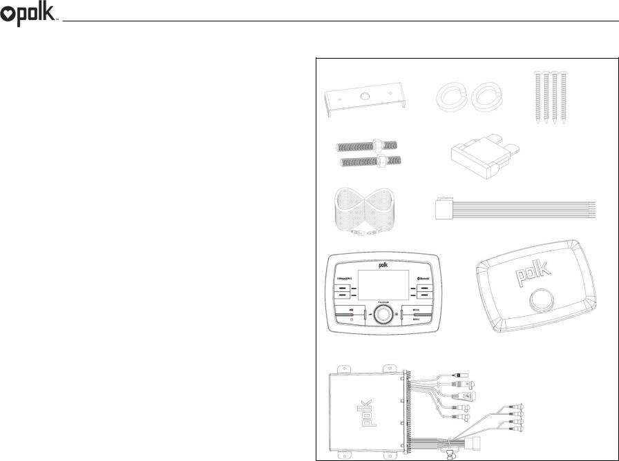
Content List
•Polk PA450UM Tuner/Amp Module
•Polk PA450UM Wired Commander
•10’ Extension Cable
•Commander Cover
•Wire Harness
•Quick Reference Guide
•Cutout Mounting Template
•Hardware Kit
-Rear Mounting Bracket
-(4x) #8 Mounting Screws
-(2x) Mounting Bolt
-(2x) Lock Washer
-(2x) Lock Nut
-15A Blade Fuse
HARDWARE KIT CONTENTS
3

PA450UM
SAFETY INFORMATION |
WARNING: |
|
|
||
When Boating |
TO REDUCE THE RISK OF FIRE OR ELECTRIC SHOCK AND INTERFERENCE, |
|
USE ONLY THE RECOMMENDED ACCESSORIES. |
||
Keep the volume level low enough to be aware of your surroundings. |
||
|
||
Protect from Water |
|
|
Do not submerge the product in water, as this can cause electric shorts, fire or |
|
|
other damage. |
|
|
Protect from the Elements |
|
|
Use the included cover to protect the wired commander from sunlight, dust, and |
|
|
water while not in use. |
|
|
Protect from High Temperatures |
|
|
Do not mount radio within close proximity of engine compartment. |
|
|
Use the Proper Power Supply |
|
|
This product is designed to operate with a 12 volt DC negative ground battery |
|
|
system. |
|
|
CAUTION: |
|
|
DO NOT OPEN COVERS AND DO NOT REPAIR BY YOURSELF. PLEASE |
|
|
REFER SERVICING TO A QUALIFIED TECHNICIAN. |
|
4
PA450UM
Installation
Before You Begin
Always disconnect the negative battery terminal
Important Notes
•Before final installation, test the wiring connections to make sure the unit is connected properly and the system works.
•Consult with your nearest dealer if installation requires the drilling of holes or other modifications to your vessel.
•Install the unit where it does not interfere with operating the vessel and cannot injure passengers.
•Use the included template to cut the installation opening.
Commander Cover
•During storage, use the included cover to prolong the life of your device by protecting the wired commander from direct sunlight, moisture, dust, and other elements.
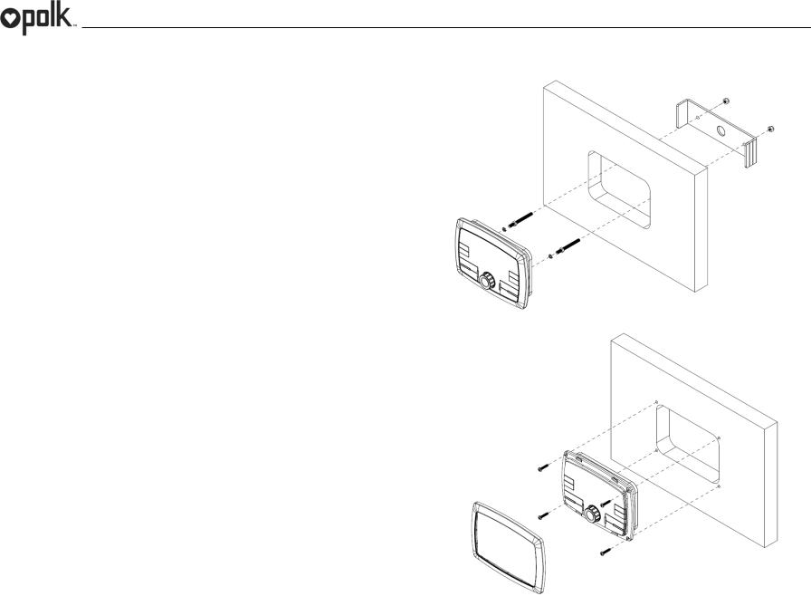
Wired Commander Mounting
•Choose a mounting area for the wired commander that is clean and flat, allowing the rear gasket to fully seal to the mounting surface.
•Secure the wired commander using either of the recommended mounting methods detailed below.
Bracket Mount
•Insert wired commander through cut-out and secure with bracket using included hardware as detailed in the diagram.
Screw Mount
•Secure the wired commander to the mounting surface using #6 stainless steel pan head screws (not included) as detailed in the diagram.
Bracket Mount
Screw Mount
5
PA450UM
Removing the Unit
To remove the commander, remove bracket mount or remove trim ring and mounting screws, then slide wired commander out of the mounting hole.
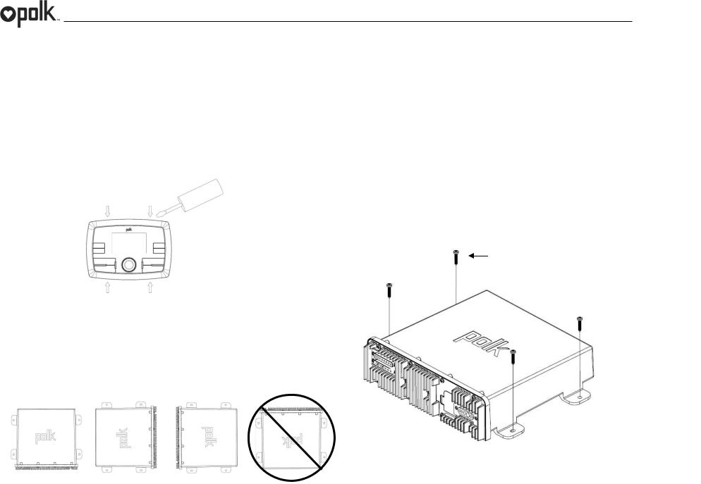
Removing the Trim Ring (Screw Mount Only)
Before removing the mounting screws, remove the trim ring first. Using a small non-metallic panel removal tool, apply the flat edge of the tool to the trim ring top latch area (as shown). Pull forward and twist to disengage the latches. Note: Use a protective surface under the removal tool so as not to damage the mounting surface.
2.Using the shortest length of the recommended size screws possible, mount the tuner/ amplifier as detailed in the diagram on the right.
3.Route the tuner/amplifier harness and cable throughout the vessel as required. Keep some slack in the harness/cables so it won't be too tight, as this can cause damage to the wires.
4.Follow the wiring diagram carefully and make certain all connections are secure with insulated crimp connectors to ensure proper operation.
5.After completing the wiring connections, reconnect the negative terminal on the battery and turn the unit on to confirm operation (vessel accessory switch must be on). If the unit does not operate, disconnect battery, recheck all wiring and refer to the trouble-shooting guide located in the back of the manual.
STAINLESS STEEL #8 SCREWS (INCLUDED)
1/8” PILOT HOLES FOR SUPPLIED SELF-STARTING SCRWS
.180 PILOT HOLES WHEN USING THREADED MACHINE SCREWS
Tuner / Amplifier Module Mounting
1.Choose a mounting area for the tuner/amplifier module that will provide plenty of ventilation to prevent the amplifier from overheating. The tuner/amplifier module can be mounted in the horizontal or vertical position. Please note that when mounting in vertical position, do not mount with the harness exit points facing straight up, as water can collect around the chassis in these areas.
6

PA450UM
WIRING
TUNER/AMP
MODULE
COMMANDER
7
 Loading...