

Polaroid SprintScan SS35, SprintScan SS35 ES, SprintScan SS35 PLUS Repair Manual

Repair Manual
Americas Business Center
Technical Services
201 Burlington Road
Bedford MA 01730
TEL: 1.781.386.5309
FAX: 1.781.386.5988
SprintScan Slide Scanner
SS35, SS35 ES, SS35 PLUS
October 1997

Slide Scanner Repair Manual Table of Contents
Table of Contents
Purpose of Manual .................................................................................................. 7
Manual Organization ............................................................................................... 7
Other Documents Required for Repair .................................................................. 7
Important Safety Instructions................................................................................. 8
1. Scanner Overview .............................................................................................. 9
Description ........................................................................................................... 11
Applications .......................................................................................................... 12
Features............................................................................................................... 1 4
Specifications ....................................................................................................... 19
Operation ............................................................................................................. 22
Setting up the Scanner ...................................................................................... 22
Installing the Software ....................................................................................... 23
Starting the Software......................................................................................... 24
Scanning the Slide/Film Strip ............................................................................. 25
Self-Check Routines............................................................................................. 26
Self-Test (Power-Up) ........................................................................................ 26
Calibration ......................................................................................................... 28
2. Functional Description....................................................................................... 31
Scanner Process Overview .................................................................................. 33
Scanner Transporter ............................................................................................ 34
Scanner Optics..................................................................................................... 37
Scanner Electronics.............................................................................................. 38
Power Supply PC Board.................................................................................... 38
Main Controller PC Board Power Distribution .................................................... 40
AC Inverter PC Board....................................................................................... 41
Image Sensor PC Board ...................................................................................... 42
CCD Image Sensor............................................................................................ 42
Associated Analog Signal Processing Support Circuitry..................................... 4 3
Main Controller PC Board..................................................................................... 4 3
Analog Signal Processing .................................................................................. 45
Digital Signal Processing ................................................................................... 45
Primary Correction ASIC................................................................................. 45
DRAM Controller (Buffer)................................................................................ 46
2

Slide Scanner Repair Manual Table of Contents
Secondary Color Correction ASIC .................................................................. 47
Color Modes ................................................................................................... 48
Scanner Control................................................................................................. 48
CCD Driver...................................................................................................... 48
Transporter Driver........................................................................................... 48
LED Indicator Driver........................................................................................ 4 8
Filter Wheel Driver .......................................................................................... 49
System Interface.................................................................................................. 49
3. Calibration and Adjustments ............................................................................. 50
Required Tools and Equipment............................................................................. 52
Warnings and Precautions.................................................................................... 53
Voltages ............................................................................................................ 53
Electrostatic Discharge Warning........................................................................ 53
Inspection and Cleaning........................................................................................ 54
Checking Scanner Self-Test (Power Up).............................................................. 56
Adjustments.......................................................................................................... 59
Power Supply .................................................................................................... 59
Focus/Magnification ........................................................................................... 60
Transporter Photo-Sensor Alignment................................................................. 69
Filter Wheel Set Photo-Sensor Tab Alignment ( Only for Slide Scanner
with Filter Wheel)............................................................................................... 70
4. Parts Replacement ............................................................................................. 72
Required Tools and Equipment............................................................................. 74
Electrostatic Discharge Warning .......................................................................... 74
Inspection and Cleaning........................................................................................ 74
Disassembly/Assembly of Electrical and Mechanical/Optical Assemblies............. 75
Top Housing....................................................................................................... 75
Removal.......................................................................................................... 75
Installation....................................................................................................... 77
Main Controller PC Board.................................................................................. 78
Removal.......................................................................................................... 78
Installation....................................................................................................... 79
3

Slide Scanner Repair Manual Table of Contents
Chassis Assembly ............................................................................................. 80
Removal.......................................................................................................... 80
Installation....................................................................................................... 81
Power Supply PC Board.................................................................................... 82
Removal.......................................................................................................... 82
Installation....................................................................................................... 83
AC Inverter PC Board........................................................................................ 84
Removal.......................................................................................................... 84
Installation....................................................................................................... 85
Replacement of Components ............................................................................... 86
Scanning Lamp .................................................................................................. 86
Scanner Fuses................................................................................................... 86
System (AC Power)........................................................................................ 86
Power Supply PC Board ................................................................................. 87
AC Inverter PC Board ..................................................................................... 88
SCSI Interface (Terminator Power) ................................................................ 89
Filter Wheel Stepper Motor (Only for Slide Scanner with Stepper Motor) ......... 90
Transporter Stepper Motor................................................................................ 91
CCD Board ........................................................................................................ 93
5. Diagnostics and Troubleshooting..................................................................... 96
Error Messages ................................................................................................... 99
Diagnostic (Digital Hardware) ............................................................................ 100
Operational........................................................................................................ 101
Calibration ......................................................................................................... 106
LabView Image Performance Test (IPT) Version 1.02-Mac................................. 113
Scanner Tester (w) Front Panel......................................................................... 113
Image Quality Test Outline ................................................................................ 118
Geometric Type Test Using GMT Target ....................................................... 118
Color Type Test Using CT Target................................................................... 118
Changing Type of Scanner Under Test ........................................................... 118
Changes to IPT Test Since LabView Version 3.1 (Summary) .............................. 119
Using Scanner Tester (W).................................................................................... 120
Required Tools and Equipment.......................................................................... 120
Initial Setup - Complete Image Performance for LabView Version 4 ................. 121
Entering Test Parameters.................................................................................. 123
Entering Optional Test Parameters.................................................................... 124
Starting Test...................................................................................................... 124
Auto Reference Finding Origin for GMT and CT Targets................................... 125
Error Reporting.................................................................................................. 126
4

Slide Scanner Repair Manual Table of Contents
Test Results ...................................................................................................... 126
Stored Test Results........................................................................................... 127
Pausing or Stopping Scanner Test..................................................................... 128
Pausing a Test in Progress............................................................................. 128
Stopping a Test in Progress ........................................................................... 128
IPT Scanner Tests - Understanding Test Results............................................... 129
Initialization Test ................................................................................................ 129
Distortion & Mag Test........................................................................................ 129
Left, Center, Right Resolution Test.................................................................... 130
Motion and Color Registration Test ................................................................... 131
Color Registration Test................................................................................... 131
Motion Test .................................................................................................... 132
Interpreting Measurements of the Color Registration & Motion Tests................ 133
Introduction ..................................................................................................... 133
Stand Alone Motion and Resolution Test Panel - Details ................................ 133
Test Panel Controls...................................................................................... 133
Test Report.................................................................................................. 134
Test Constraints ............................................................................................. 134
Analysis .......................................................................................................... 134
Left and Right Misalignment Windows ............................................................ 137
Mag and Tilt Adjustment Effects..................................................................... 137
Motion Problem Examples ................................................................................. 138
Uniformity II Test ............................................................................................... 140
Part 1 ............................................................................................................. 140
Part 2 ............................................................................................................. 140
Part 3 ............................................................................................................. 142
Part 4 ............................................................................................................. 142
Dark Noise II Test ............................................................................................. 144
Negative Calibration........................................................................................... 145
Error Reporting.................................................................................................. 145
Test Result Folder/Directory.............................................................................. 145
CCD Configuration............................................................................................. 146
Determining CCD Configuration Using Scanner Tester ................................... 146
IPT Scanner Test Descriptions............................................................................. 147
Motion and Color Registration Test ................................................................... 147
Static (Color Registration) ................................................................................. 147
Mean Vertical ................................................................................................. 147
Mean Horizontal.............................................................................................. 147
Dynamic (Motion Effects) .................................................................................. 148
Dark Noise II Test ............................................................................................. 149
Dark Uniformity Response (Streaks) .............................................................. 149
Dark Uniformity Response (Noise).................................................................. 150
Dark Uniformity Response (Fourier) ............................................................... 151
Control Panel.................................................................................................. 152
Uniformity II Test ............................................................................................... 152
5

Slide Scanner Repair Manual Table of Contents
Uncorrected Light Uniformity Test...................................................................... 153
Illumination ......................................................................................................... 155
Uncorrected Dark Uniformity Test...................................................................... 155
Bad Pixel Flag................................................................................................. 155
Uniformity II Stand - Alone Test Control Panel................................................... 156
6. System Diagrams ............................................................................................... 157
Power Supply Specification (Sheets 1 - 4) ........................................................... 159
AC Inverter PC Board .......................................................................................... 163
Image Sensor (CCD) PC Board Schematics (Sheets 1 - 3) ................................. 164
SS35/SS35 ES Main Controller PC Board Schematics (Sheets 1 - 8) ................. 167
SS35 PLUS Main Controller PC Board Schematics (Sheets 1 - 9)....................... 175
Appendix .................................................................................................................. 184
SS35 & 35 ES Firmware/Hardware Update History ............................................. 186
6

Slide Scanner Repair Manual Table of Contents
Purpose of this Manual
This Repair Manual is intended as a training and reference guide for the Polaroid and
Polaroid-authorized technical personnel servicing the SS35/SS35 ES/SS35 PLUS slide
scanner's.
Organization of this Repair Manual
Scanner Overview. General information about scanner capabilities and applications.
Functional Description. Detailed explanations of various slide scanner components and
systems for help in diagnosing problems and performing other service.
Calibration and Adjustments. Procedures for checking slide scanner self-test (calibration)
or for solving problems detected by the LabView Tester or setup after component
replacement.
Parts Replacement. Step-by-step procedures for assembly and component level
replacement.
Diagnostics and Troubleshooting. Internal diagnostic software for help in diagnosing
scanner malfunctions. It also gives a detailed explanation of the provided LabView Tester
for help in diagnosing poor image quality.
Schematic Diagrams. Electronic schematics for use as troubleshooting and reassembly
aids.
Other Documents Required for Repair
Effective repair for the slide scanner's also requires familiarity with the following documents in
addition to this Repair Manual:
• SS35/SS35 ES/SS35 PLUS User Guides
• SS35/SS35 ES/SS35 PLUS Slide Scanner Repair Manual
• SS35/SS35 ES/SS35 PLUS Slide Scanner Parts Catalog
• EZ - SCSI Lite Software Manual (IBM and Mac versions)
• SS35/SS35 ES/SS35 PLUS Software Manual (IBM and Mac versions)
• LabView User's Guide
7

Slide Scanner Repair Manual Table of Contents
IMPORTANT SAFETY INSTRUCTIONS
When using the Slide Scanner, basic safety precautions should always be followed including the
following:
• Read and understand all instructions before using.
• Position the cord so that it will not be tripped over, pulled, or contact hot or sharp surfaces.
• If an extension cord is necessary, a UL recognized grounded cord with a rating at least
equal to that of the slide scanner should be used. Extension cords rated for less amperage
may overheat. Connect the slide scanner to a grounded outlet.
• Always turn the host computer OFF and then the slide scanner OFF before unplugging.
• Always unplug the slide scanner from the electrical outlet before cleaning and servicing and
when not in use. Never pull the cord from the outlet. Grasp and pull the plug from the outlet
to disconnect.
• Do not disassemble the slide scanner, but take it to a qualified service person when service
or repair work is required. Incorrect assembly can cause electrical shock when the slide
scanner is used subsequently.
8

Slide Scanner Repair Manual Scanner Overview
1. Scanner Overview
9

Slide Scanner Repair Manual Scanner Overview
1. Scanner Overview
Contents
Description ......................................................................................................... 11
Applications ........................................................................................................ 12
Features .............................................................................................................. 14
Specifications ..................................................................................................... 19
Operation ............................................................................................................ 22
Setting up the Slide Scanner.............................................................................. 22
Installing the Software ....................................................................................... 23
Starting the Software......................................................................................... 24
Scanning the Slide/Film Strip ............................................................................. 25
Self-Check Routines .......................................................................................... 26
Self-Test (Power-Up) ........................................................................................ 26
Calibration ......................................................................................................... 28
10

Slide Scanner Repair Manual Scanner Overview
Description
This section of the Repair Manual gives an overview of the SprintScan 35, the SprintScan 35
ES, and the SprintScan 35 PLUS slide scanner. It only provides the necessary information
pertaining to features and specifications for each slide scanner.
For detailed information pertaining to setting up the slide scanner, installing and starting their
software, assigning SCSI ID's and checking SCSI connections, scanning transparencies, and
using application software, refer to the applicable slide scanner User Guide.
The slide scanners are desktop, fixed-format, high-speed 35 mm transparency film scanners,
capable of scanning positive and negative media, mounted and unmounted transparencies and
unmounted transparency filmstrips.
Each system (Figure 1-1) consists of a:
• Slide Scanner
• Power Cord
• SCSI cable with 25-pin and 50-pin connector ends
• SCSI terminator (Supplied only with SprintScan 35 ES)
• SprintScan software diskette
• Adaptec AT-to-SCSI Host Adapter with EZ-SCSI Lite application diskette and
documentation (Windows version only)
• Adobe PhotoDeluxe CD (Mac/Windows)
• Filmstrip carrier for negative strip or unmounted slide film
11

Slide Scanner Repair Manual Scanner Overview
Applications
Table 1-1 indicates a partial list of applications for each slide scanner. For a more detailed list
of applications for each slide scanner, refer to the applicable slide scanner User Guide.
Table 1-1. Slide Scanner Applications
Applications\User Groups SS 35/SS 35 ES SS 35 PLUS
Digital Design:
Graphic Designs •• •
Corporate Design Departments •• •
Advertising Agencies •• •
Web-Page Design ••
Multimedia Design ••
Publishing:
Catalog Publishers •• •
Magazine Publishers •• •
Newspapers •• •
Printing:
Prepress Houses •
Printers •
Photo Retouching:
Studio Photography •• •
ProPhoto Labs •• •
• • - Ideally suited.
12

Slide Scanner Repair Manual Scanner Overview
SprintScan 35/35ES
Polaroid SprintScan 35
SprintScan 35 PLUS
Polaroid SprintScan 35 PLUS
Figure 1-1. Slide scanners
13

Slide Scanner Repair Manual Scanner Overview
Features
Table 1-2 list and describes the features of the slide scanners (Figure 1-2).
Table 1-2. Slide Scanner Features
Feature Description
Power LED Indicator This green LED indicator lights to indicate when the
slide scanner power is turned on.
Note: During power-up the slide scanner initiates its
self-test mode.
Ready LED Indicator This yellow LED indicator lights to indicate when the
slide scanner is ready to operate (passed power up
self-test).
Notes: • This indicator continually blinks while the
slide scanner cycles through its self-test.
• Upon completion, this indicator lights steady
to indicate that the slide scanner is ready to
operate.
Top Access Slot The top access slot is used when scanning 35 mm slide
transparencies.
Side Access Slot The side access slot is used when scanning unmounted
slides and 35 mm filmstrips using the filmstrip carrier
included in the accessory kit.
Filmstrip Carrier Included with the accessory kit.
Used to scan a 35 mm negative strip or an unmounted
slide. Supports 35 mm filmstrips from 1 - 6 frames.
Release Button This button is used to release the front cover when
replacing the lamp. (Spare lamp located inside front
cover.)
Power On/Off (1/0) Switch This switch turns the slide scanner power on or off. The
green Power LED lights to indicate that the slide scanner
is turned on.
14

Slide Scanner Repair Manual Scanner Overview
Table 1-2. Slide Scanner Features (Cont'd)
Feature Description
Power Receptacle Standard receptacle with ground.
Power Cord Standard cord with ground.
Power Fuse Receptacle The fuse receptacle contains two fuses: active and
(SS35 Only) spare.
The active fuse protects the slide scanner's electronics
from any sudden surges or overloads.
Note: If the active fuse fails (blows), always attempt to
find out the cause of the malfunction before
replacing the blown fuse with the provided spare.
Replace the spare fuse with a new one as
soon as possible.
Power Fuse Not user accessible. Located on power supply PC
(SS35 PLUS) board.
SCSI ID Selector/Indicator The slide scanner's SCSI ID is preset at the factory
to 6.
SCSI ID position 7 is reserved for the SCSI adapter to
which the SCSI device(s) are connected.
Note: DO NOT change this value unless other SCSI
devices are attached to the slide scanner and
one of them is assigned to SCSI value 6.
If the preset SCSI value must be changed, refer
to the applicable slide scanner User's Guide for
detailed instructions on how to change the slide
scanner's SCSI value.
15

Slide Scanner Repair Manual Scanner Overview
Table 1-2. Slide Scanner Features (Cont'd)
Feature Description
SCSI Receptacles SS35/SS35 ES: (Top and Bottom)
Two (2) 50-pin standard SCSI receptacles.
SS35 PLUS:
One (1) 50-pin standard SCSI receptacle.
One (1) 25-pin standard SCSI receptacle.
SCSI Cable This cable (25-pin and 50-pin connector ends) connects
th eslide scanner to the host computer.
Note: The 50-pin end of the SCSI cable connects to the
top SCSI receptacle. The 25-pin end of the SCSI
cable connects to the 25-pin SCSI port at the
rear of the host computer (Adaptec AT-to-SCSI
Host Adapter port for Windows version).
SCSI Terminator SS35/SS35 ES:
SCSI terminator connects to the bottom receptacle.
SS35 PLUS:
SCSI terminator built in. To activate SCSI terminator,
set SCSI terminator switch to its ON position.
Notes: • To function properly, a SCSI chain must be
terminated at each end.
• The Adaptec AT-to-SCSI Host Adapter for
Windows version is internally terminated, which
means that it is the first one of the required
terminators.
• If the slide scanner is the only SCSI device to
be connected to the host computer, connect the
SCSI terminator to the bottom SCSI receptacle.
For SS35 PLUS turn on the terminator switch.
16

Slide Scanner Repair Manual Scanner Overview
Table 1-1. Scanner Features (Cont'd)
Feature Description
SCSI Terminator
(Cont'd) Warning: If the slide scanner is being added to an
existing SCSI device chain, make sure that
only two SCSI terminators (internal or
external) exist in the SCSI device chain.
More than two SCSI terminators in the SCSI
device chain can damage the host computer
or the devices.
Adaptec AT-to-SCSI This adapter provides the interface through which the
Host Adapter slide scanner and host computer communicate.
(Windows Version ONLY)
Notes: • The adapter is preset at the factory for default
interrupts and port address values.
• Host adapter not included with all models
EZ-SCSI Lite Software Included with the Adaptec AT-to-SCSI Host Adapter.
(Windows Version ONLY)
This software application is used to configure the host
computer for the SCSI adapter. It also provides
additional driver files for the SCSI interface.
Notes: • The host computer must always be restarted
after the EZ-SCSI Lite software is installed.
• If necessary, contact Adaptec for latest version
drivers. Drivers can be downloaded from
Adaptec's website at:
http://www.adaptec.com
17

Slide Scanner Repair Manual Scanner Overview
Table 1-1. Scanner Features (Cont'd)
Feature Description
SprintScan 35 Software Included with the slide scanner.
This software includes the SprintScan application and the
Scanner Control Panel which is a TWAIN source driver.
Note: TWAIN is a software protocol that allows
applications to use image-acquisition devices,
such as the SprintScan 35 Slide Scanner and
other image digitizers.
The software allows the scanned image to be
manipulated. Manipulation includes rotating,
cropping, zooming, re-sizing, and changing the
output image. For more detailed information
pertaining to image manipulation refer to the
applicable slide scanner User's Guide.
Adobe PhotoDeluxe This software application allows the scanned image to
be manipulated. Manipulation includes rotating, cropping,
zooming, re-sizing, and changing the output image. For
more detailed information pertaining to image manipulation
refer to the applicable slide scanner User's Guide.
18

Slide Scanner Repair Manual Scanner Overview
Front
Rear
Ready
LED Indicator
Power
LED Indicator
Polaroid SprintScan 35
Release
Button
Top
Access Slot
SCSI
ID Selector
Side
Access Slot
Power
Receptacle
SCSI Receptacles
SS35/SS35 ES
SS35 PLUS
(Top and Bottom)
Terminator Switch
Power On/Off
(1/0) Switch
SCSI
Power On/Off
(1/0) Switch
Fuse
Receptacle
Fan
SCSI Receptacles
(Top and Bottom)
SCSI
ID Selector
Power
Receptacle
Fan
Figure 1-2. Slide scanner features
19

Slide Scanner Repair Manual Scanner Overview
Specifications
Physical:
Dimensions - 5 x 7 x 10 inches (13 x 18 x 26 cm)
Weight - approximately 5.5 pounds (2.5Kg)
Power:
Operating Voltage - 105 - 130 VAC @ 48 - 62 Hz (USA)
- 90 - 110 VAC @ 48 - 62 Hz (Japan)
- 190 - 210 VAC @ 48 - 62 Hz
- 210 - 260 VAC @ 48 - 62 Hz (Europe)
Idle Power - 30 Watts @ 115 VAC, 60 Hz (lamp off)
Operating Power - 35 Watts @ 115 VAC, 60 Hz (lamp on)
Light Source:
Lamp - Phillips Coolwhite (US - Type TL4W/33)
(European Equivalent - Type F4T5)
Environmental Conditions:
Operating Temperature - 50°F (10°C) to 104°F (40°C)
Optimum @ 60°F (16°C) to 80°F (27°C)
Storage Temperature - 20°F (-30°C) to 160°F (70°C)
Operating Relative Humidity - 20% to 80%
Optimum @ 30% to 60%
Media Type/Orientation
35 mm Slide Size - 1.4" x 1.4" (36 mm x 36 mm) mounted, including
ANSI-standard plastic mounts
35mm Slides, Mounted - Landscape/portrait orientation, superslide (36mm x 36mm)
35mm Slides, Unmounted - Landscape orientation only (Used with filmstrip carrier)
Filmstrips - 35 mm filmstrips, unmounted, in lengths of
Scanning:
Time - Under 30 seconds
Resolution - 127 dpi - 2700 dpi
Maximum Scan Area - 36 mm x 24 mm or 24 mm x 36 mm
1- to - 6 frames (Used with filmstrip carrier)
20

Slide Scanner Repair Manual Scanner Overview
Host Computer Platforms: Macintosh IBM PC or Equivalent
Operating Systems
Hardware Requirements
RAM
Monitor
Digitized Image
Formats
- System 7.1 or higher MS Windows 3.1 or higher,
Windows 95, Windows NT 4.0
- Power PC Mac, Mac II, Minimum 386SX @16Mhz
Quadra or Centris with Recommended 486 @ 33Mhz
floating point with floating point
co-processor co-processor
- Recommended: 24 MB Recommended: 24 MB
- VGA Color Monitor and VGA Color Monitor and
Video Card Video Card
Recommended: True Color Recommended: True Color
Video Card (24-bit color) Video Card (24-bit color)
with at least 800 x 600 with at least 800 x 600
resolution resolution
- TIFF, PICT, RAW TIFF, PCX, GIF, BMP,
TGA, JPG
Software: (Included with Slide Scanner)
Diskettes/CD - Adobe PhotoDeluxe SprintScan 35 for Windows 3..x
Version 2.5.1 or Later SprintScan 35 for windows 95
- SprintScan 35 ES/PLUS Adaptec AT-to-SCSI Host
Adapter with EZ-SCSI Lite
- Apple Shared Library (Not included with all Models.)
(Required for Non-Power PC's.)
21
Slide Scanner Repair Manual Scanner Overview
Operation
The following operational flow diagrams (Figures 1-3 through 1-6) briefly describe how to setup
the slide scanners, install and start their software, assign their SCSI ID value, and scan a
mounted or unmounted 35 mm transparency using the SprintScan 35 application software.
Each operational flow diagram is intended to be used only as a Quick reference for the repair
person. For detailed information pertaining to the information in each operational flow diagram
(setting up the slide scanner, installing and starting its software, assigning its SCSI ID and
checking the SCSI connection, and scanning a 35 mm transparency using SprintScan, refer to the
applicable slide scanner User's Guide.
Setting Up the Slide Scanner
Windows Version
SS35/SS35 ES
Connect
SCSI Terminator
to Scanner
Install
Adaptec SCSI
Adapter to Host
Assign /Select
SCSI ID
Connect
Scanner to Host
2
1
SS35 PLUS
Turn On
SCSI Terminator
Switch
Mac Version
Set to 6
2
Notes: 1 - If host already has a SCSI adapter, add slide scanner to SCSI chain.
2 - If slide scanner is only, or last device, in SCSI chain.
DO NOT CONNECT SS35 ES SLIDE SCANNER TO SCSI CHAINS
WITH HARD DRIVES (Applies to PC, only and slide scanners with
firmware version 1.02 or lower).
Figure 1-3. Setting up slide scanner
Turn On Scanner,
then Host
22
A

Slide Scanner Repair Manual Scanner Overview
Installing the Software
Windows Version
Install Adaptec
EZ-SCSI Lite/EZ-SCSI
Software
EZ-SCSI Lite/EZ-SCSI:
• Configures host computer
for SCSI adapter
• Provides additional driver
files for SCSI interface
SprintScan:
• Provides Scanner Control
Panel
• Provides additional driver
files for SCSI interface
A
Reboot
Host
Install
Applicable
SprintScan 35
Software
Mac Version
Install
Adobe PhotoShop
Software
Adobe Photoshop:
• Automatically transfers
final scans into Adobe
PhotoShop
• Provides digitized image
manipulation
Figure 1-4. Installing sprintscan 35 software
Reboot
Host
Check
SCSI
Connection
Turn Off Host,
then Scanner
23
B

Slide Scanner Repair Manual Scanner Overview
Starting the Software
Windows Version
Click on
Adobe PhotoShop
Click on
File Menu
Click on
Import
Select
Twain_32 Source,
then SprintScan 32-Bit
1
B
Turn On Scanner,
then Host
Mac Version
Click on
Adobe PhotoShop
Click on
File Menu
Click on
Import/Acquire
Select
SprintScan 35...
Click on File Menu
Select
Twain_32
Note: 1 - Required for first scan only.
Figure 1-5. Starting sprintscan 35 software
Scanner Control Panel
Displays
Scan
Slide/Film Strip
C
24

Slide Scanner Repair Manual Scanner Overview
Scanning the Slide/Film Strip
C
Scan
Scan
Mounted Slide
Insert
Mounted Slide
into Scanner
Top Slot
Unmounted
or
Film Strip
Open Carrier
Scan
Slide/Film Strip
Place
Unmounted Slide
or
Film Strip
into Carrier
Insert
Carrier into
Scanner
Right-Side Slot
Note: Refer to the applicable slide scanner User's Guide for information pertaining to
scanning a mounted slide, unmounted slide or film strip.
Figure 1-6. Scanning a slide/film strip
25

Slide Scanner Repair Manual Scanner Overview
Self-Check Routines
The slide scanner provides two internal self-check software routines that are used to
automatically check (verify) its operation. The two internal self-check software routines are:
• Self-Test (Power-Up)
• Calibration
Self-Test (Power-Up) Routine
When the slide scanner is turned on, the self-test (power-up) routine is automatically invoked.
This routine checks and verifies the following operations:
• Initializes all system electronics (image sensor and main controller PC boards).
• Finds calibration window (Transporter moves shutter to its calibration window
position and stops.)
Note: If the calibration window position can not be found, the transporter moves
to its top position and then returns the shutter to what it thinks is the correct
position.
Refer to the simplified flow diagram shown in Figure 1-7 for the necessary steps to self-test the
slide scanner during power-up.
Upon completion (passed self-test), the transporter returns to its home position and the Ready
LED lights steady to indicate that the slide scanner is ready to operate.
Notes: • If the yellow Ready LED continually blinks, the slide scanner failed its self-test.
Run the LabVIEW IPT test to determine why the slide scanner failed its
self-test . (Refer to the applicable LabVIEW test in Section 5 of this Repair
Manual for detailed instructions on how to run the LabVIEW test procedure.)
• If the yellow Ready LED does not light after the self-test is performed, turn off
the slide scanner (power-down), wait approximately 10 seconds and then
power-up again.
Causes of self-test (power-up) failure are usually due to a defective EEPROM, incorrect
EEPROM data, the inability to find the calibration window, or a blown SCSI terminator fuse.
Refer to Section 5 in this Repair Manual for self-test errors.
26

Slide Scanner Repair Manual Scanner Overview
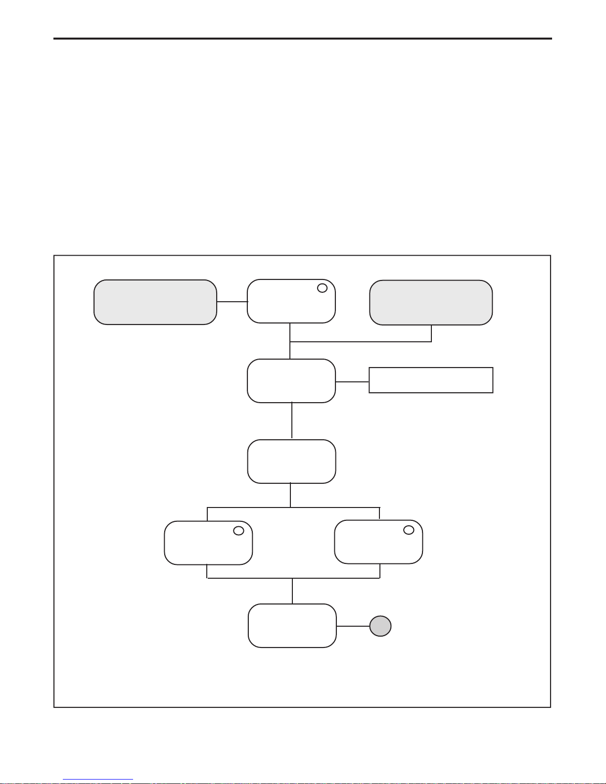
Self-Test
Initializes (Resets)
System
Electronics
Filter
Wheel
**
Transporter SCSI
A/D
Converters
*
ASIC's
*
*
Ready LED
Continually Blinks
Self-Test
Failed
Run LabVIEW Test
(See Section 5 for Details)
Transporter
Seeks Calibration
Window
Self-Test
Completed
*
*
Ready LED
Lights Steady
Self-Test
Passed
* For SS35 PLUS, self-test of these components only occurs after the host software downloads (initializes) programmable code.
** Filter Wheel used only on early SprintScan Models.
Figure 1-7. Self-Test simplified flow diagram
27

Slide Scanner Repair Manual Scanner Overview
Calibration
For SS35/SS35 ES slide scanners, the first calibration is performed at the first requested scan.
It is also performed when the slide scanner detects a specified amount of drift in the lamp or
front end during subsequent scans. The SS35 PLUS performs a full calibration before each
scan.
Refer to Figure 1-8 for a simplified flow diagram of the SS35/SS35 ES slide scanner calibration
routine and to Figure 1-9 for a simplified flow diagram of the SS35 PLUS slide scanner
calibration routine.
Upon completion (passed calibration), the Ready LED indicator lights steady to indicate that the
slide scanner is ready to operate.
Note: The Ready LED indicator continually blinks while the slide scanner cycles through its
calibration.
The following types of adjustments occur during the first calibration:
• Base line integration time to ensure a minimum signal and mitigation of saturation
• Analog gain and offset for base line neutral settings
• Digital uniformity offset calibration
• Digital uniformity gain calibration
• Bad pixel identification
Subsequent scans may require additional analog gain and offset and/or integration time
adjustments to accommodate white points requested by the host or film tables, as a function of
the specific calibration algorithms.
A drift check is also performed with each scan to verify the stability of the front end. Each
calibration that requires a significant change in the front end settings necessitates a
recalculation of the digital uniformity offset correction during the actual scan.
Causes of calibration failure are usually due to a defective lamp, obstructions in the optical path,
a defective sensor (CCD) PC board, a defective main controller PC board, a defective filter, or
a misaligned filter wheel (Original SS35 only).
Refer to Section 5 in this Repair Manual for a detailed list and definition of all calibration type
errors.
28

Slide Scanner Repair Manual Scanner Overview
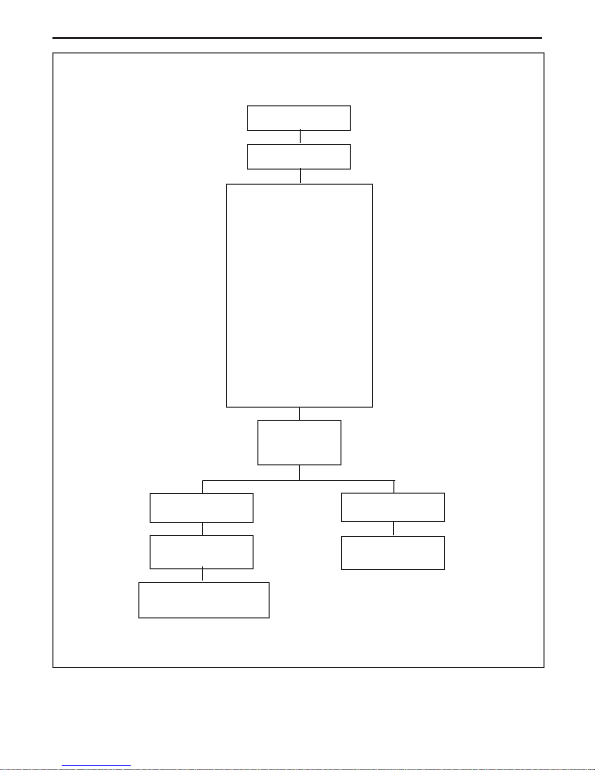
SS35/SS35 ES
Calibration Routine
Start
First Scan
Calibrate
Check and adjust, if
necessary:
• Base line integration time
to ensure a minimum signal
and mitigation of saturation
• Analog gain and offset for
base line neutral settings
• Digital uniformity
offset calibration
• Digital uniformity
gain calibration
Start
Subsequent Scans
Check
Drift in Lamp
or
Front End
Fail
Pass
• Bad pixel identification
• Drift test
Calibration
Completed
Fail
Ready LED
Continually Blinks
No Scan
Run LabVIEW Test
(See Section 5 for Details)
Pass
Ready LED
Lights Steady
Figure 1-8. Calibration simplified flow diagram
Scan
29
Slide Scanner Repair Manual Scanner Overview
SS35 PLUS Calibration
Routine
Start Scan
Calibrate
Check and adjust, if
necessary:
• Base line integration time
to ensure a minimum signal
and mitigation of saturation
• Analog gain and offset for
base line neutral settings
• Digital uniformity
offset calibration
• Digital uniformity
gain calibration
• Bad pixel identification
• Drift test (lamp/front end)
Fail
Ready LED
Continually Blinks
No Scan
Run LabVIEW Test
(See Section 5 for Details)
Calibration
Completed
Pass
Ready LED
Lights Steady
Scan
Figure 1-9. Calibration simplified flow diagram
30
 Loading...