

Page 1
Repair Manual
Americas Business Center
Technical Services
201 Burlington Road
Bedford MA 01730
TEL: 1.781.386.5309
FAX: 1.781.386.5988
Spectra/Image One Board
September 1996
Page 2

Table of Contents
Page
Section 1 - General Description........................................................................ 5
Scope of This Addendum ............................................................................... 5
Spectra Pro/Image Pro/Minolta Pro Operating Differences ............................. 5
Spectra Pro/Image Pro/Minolta Pro Performance Differences......................... 7
Spectra Pro/Image Pro/Minolta Pro External Physical Differences .................. 8
Section 2 - Disassembly and Reassembly ...................................................... 9
Special T ools.................................................................................................. 9
Cautions and Reminders ................................................................................ 10
Removing Mid-Cover...................................................................................... 11
Disassembling Mid-Cover .............................................................................. 12
Removing Ranging Board............................................................................... 14
Replacing Ranging Board............................................................................... 17
Removing LCD Board from Ranging Board ................................................... 18
Reconnecting LCD Board to Ranging Board................................................... 19
Removing One Board Strobe/Exposure Module Assembly.............................. 20
Section 3 - Testing and Adjustments ............................................................... 23
Functional T est................................................................................................ 23
Star Tester Model 12650-3 Description........................................................... 33
Star T ester Setup and Pre-Test Checks........................................................... 36
Order of Spectra Pro/Image Pro/Minolta Pro System T ests ............................. 39
Ambient Exposure T est................................................................................... 41
Strobe Exposure (Graywall) T est ..................................................................... 43
ZLS (Zonal Lumen Seconds) Graywall T est ..................................................... 45
Hybrid (ZLS/Blade Speed) T est ...................................................................... 47
Blade Speed Test........................................................................................... 49
Spectra Pro/Image Pro/Minolta Pro Star T ester Specifications........................ 50
Ambient Exposure Calibration Slide Adjustment ............................................. 51
IR Strobe Exposure Calibration Slide Adjustment............................................ 53
Hybrid Adjustment (Opening Blade Spring)..................................................... 55
Blade Speed Adjustment (Opening Blade Spring............................................ 56
Solenoid 1 Adjustment for Quintic Position...................................................... 57
2
Page 3

Section 4 Spectra Pro/Image Pro/Minolta Pro Troubleshooting.................... 59
Basic Requirements and Guidelines............................................................... 59
Abbreviations Used in This Section ................................................................ 62
Operating Problems and T ypical Causes ........................................................ 63
Wire Connections and T est Points .................................................................. 73
Schematic Diagrams...................................................................................... 74
List of Illustrations
Figure Page
1-1 Spectra Pro/Image Pro/Minolta Pro Electronic Control Panel..................... 6
1-2 Spectra Pro/Image Pro/Minolta Pro External Physical Differences............. 8
2-1 Proper Removal of a Typical Wire Connector ............................................ 10
2-2 Removing Hinge Pins and Mid-Cover........................................................ 11
2-3 Removing Eye Cup and Buttons from Mid-Cover ....................................... 12
2-4 Removing LCD Window from Mid-Cover................................................... 13
2-5 Ranging Board and Connectors for J1, J2 and J3...................................... 14
2-6 Releasing Connectors from Ranging Board............................................... 15
2-7 Releasing Ranging Board Wire Connections............................................. 16
2-8 Reconnecting J1, J2 and J3 to Ranging Board .......................................... 17
2-9 Removing LCD Board............................................................................... 18
2-10 Replacing LCD Board............................................................................... 19
2-1 1 Disconnecting One Board Strobe/Exposure Module.................................. 20
2-12 Removing J8 from One Board Strobe/Exposure Module ............................ 21
2-13 Removing Photodiode Retainer................................................................. 22
3-1 Setup for Spectra Pro/Image Pro/Minolta Pro Functional T est.................... 24
3-2 Closing Door Latch ................................................................................... 25
3-3 LCD Control Panel at Completion of Dark Slide ........................................ 26
3-4 Covering Transducer to Stimulate Infinity Exposure.................................... 28
3-5 Quintic Lens Moves to Short-Distance Setting ........................................... 29
3-6 Quintic Lens Moves to Infinity Setting ......................................................... 31
3-7 Star T ester 12650-3 Controls and Indicators (See text for description) ....... 35
3-8 Locating Star T ester in Relation to Graywall Target..................................... 36
3-9 Tripping Spectra System Door Switch to DOWN Position.......................... 37
3-10 Positioning Camera on Horn against Star T ester ....................................... 38
3-1 1 Display for Flash, Autofocus, Audio and Exposure Adjust OFF .................. 42
3
Page 4

3-12 Display for Flash, Autofocus ON , Audio and Exposure Adjust OFF ........... 43
3-13 Display for Flash ON , All Other Functions OFF.......................................... 45
3-14 Display for Flash and Autofocus ON, All Other Functions OFF ................... 47
3-15 Display for Flash and Autofocus and Audio OFF........................................ 49
3-16 Removing Top Cover from Camera (See Section 2 for Details) ................. 51
3-17 Adjusting Ambient (Visible Light) Calibration Slide.................................... 52
3-18 Adjusting IR Strobe Exposure Calibration Slide ......................................... 53
3-19 Hybrid Adjustment (Opening Blade Spring T ension Adjustment)................. 55
3-20 Adjusting Solenoid 1 to Change Quintic Speed ......................................... 58
4-1 One Board Strobe/Exposure Module Connections on Ranging Board........ 60
4-2 Elastomeric “Zebra” Connector.................................................................. 60
4-3 Initial Test Procedure for Ranging Board and LCD Board .......................... 61
4-4 Wire Connections, T est Points: Strobe/Exposure Module
and Ranging Board ................................................................................... 73
4-5 One Board Spectra Pro/Image Pro/Minolta Pro System Schematic ........... 75
4-6 One Board Strobe/Exposure Module Schematic........................................ 76
4-7 Ranging Board Schematic ........................................................................ 77
4-8 Features Module and Display Module Schematic ...................................... 78
4
Page 5

Section 1 - General Description
Scope of This Addendum
This Service Manual addendum describes only those One Board Spectra Pro/Image
Pro/Minolta Pro mechanical parts, electronic circuits, operating modes and service
procedures that are different from those of the Spectra camera. Information common to
One Board Spectra Pro/Image Pro/Minolta Pro cameras and Spectra cameras is not
included in this addendum. Refer to Spectra Service Manual for this common
information.
To use this addendum effectively , you should also be familiar with the design, operation,
disassembly and calibration information presented in the Spectra Manual.
This addendum applies only to Spectra Pro/Image Pro/Minolta Pro cameras with the One
Board Strobe/Exposure Module Assembly (Part No. 1B0632A) installed. (These cameras
can be identified by the letter G as the tenth character in their serial numbers.) For
servicing Spectra Pro/Image Pro/Minolta Pro cameras without the One Board assembly ,
see Spectra Pro/Image Pro Camera Service Manual Addendum of January , 1990.
The name Spectra Pro as used in this addendum refers to the Spectra Pro, Image Pro
and Minolta Pro cameras unless otherwise noted.
Spectra Pro/Image Pro/Minolta Pro Operating Differences
The major differences between Spectra Pro/Image Pro/Minolta Pro cameras and
Spectra cameras relate to the operating modes available to the user, how they are
selected and how their status is displayed.
5
Page 6
The Spectra Pro/Image Pro/Minolta Pro has the following operating features:
• Automatic (sonar) focusing or manual focus distance setting
• Manual shutter opening and closing (bulb mode)
• Programmable time exposures (1-12- seconds)
• Automatic sequential exposures at programmable intervals
• Up to five exposures on a single frame
• Exposure compensation for severely backlit subjects
• Exposure lighten/darken adjustment
• Tilting accessory strobe
• Sound on or off (tone, chime and beep signals)
• Digital (LCD) display of exposures remaining, subject distance, time exposure
duration, interval between multiple time exposures and elapsed time in “bulb” mode
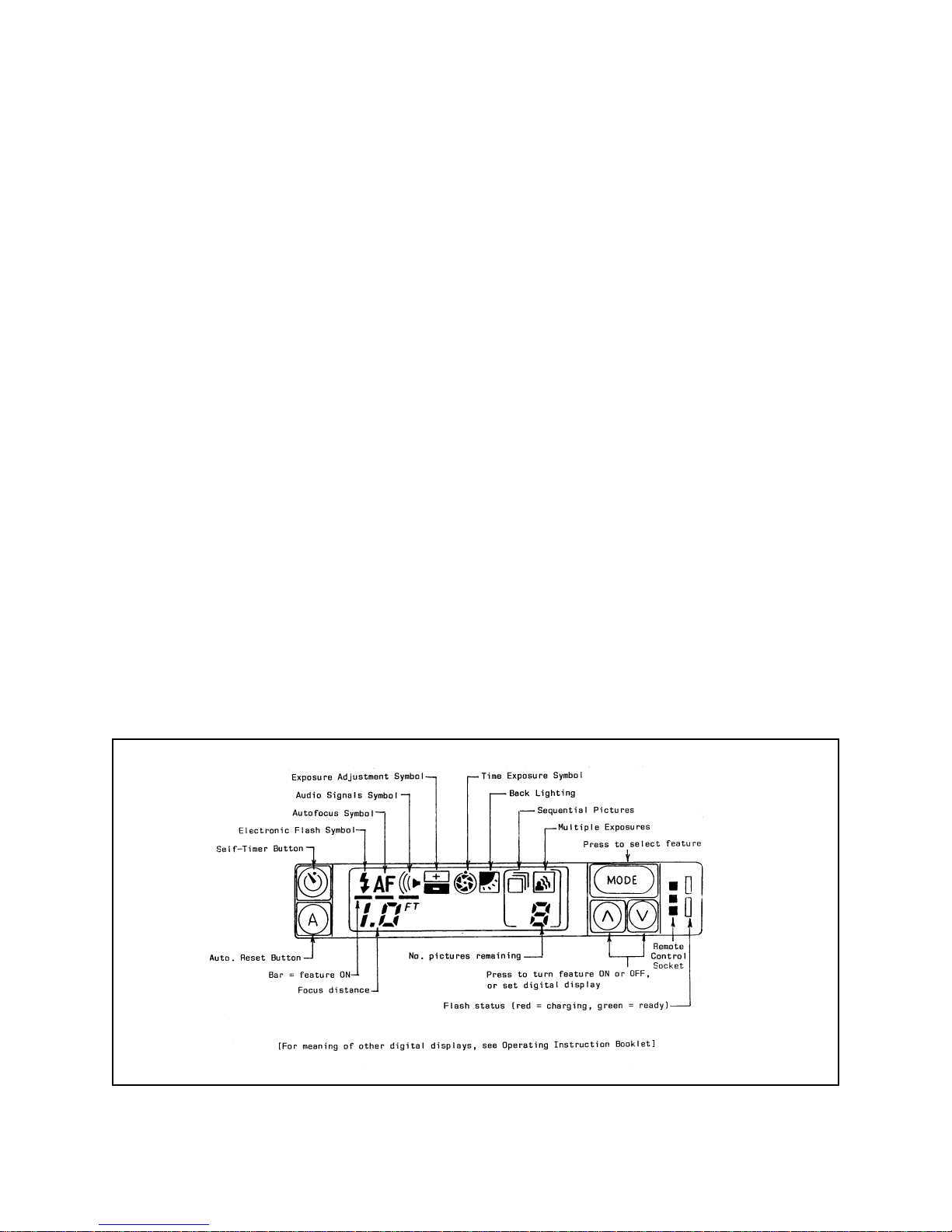
These operating modes are selected, programmed and displayed by the buttons and LCD
displays on the control panel (Figure 1-1).
Figure 1-1. Spectra Pro/Image Pro/Minolta Pro electronic control panel
6
Page 7

Pressing MODE repeatedly displays one feature symbol after another; up and down
arrows (_and_) turn the feature on or off and set digital displays; A resets the camera to
fully automatic operation. When a feature is ON (active), a horizontal bar appears below
the corresponding symbol on the LCD panel.
Note: For more information on these features, see Spectra Pro/Image Pro/Minolta Pro
Operating Instructions.
Spectra Pro/Image Pro/Minolta Pro Performance Differences
Several features to improve exposure accuracy and picture sharpness have been incorporated in the Spectra Pro/Image Pro/Minolta Pro design. These include the following:
• Improved lens
Spectra Pro/Image Pro/Minolta Pro cameras have color corrected, coated, f/10,
125mm triplet glass lenses.
• Intentional ambient overexposure to brighten scene
For light levels greater than 624 cd/ft2, a limited exposure kickup occurs to produce
a bright picture (truer whites, better facial exposure) without sacrificing detail.
• Double measurement of ambient brightness
Camera electronics remeasure the scene brightness when the second stage of the
shutter button is closed. This ensures that the latest data is used in the exposure
calculation, preventing errors caused by previewing one scene then shooting another
without releasing the S1 button.
• Intermediate fill flash mode
This additional strobe exposure program mode allows mixing a 50% flash contribution
with a 50% ambient contribution for light levels between 8 and 24 cd/ft2. This
brightens the backgrounds of low-light pictures and increases the shadow fill at
higher levels.
• Bias focus
When available depth of field permits, the Spectra Pro intentionally focuses one or
two zones behind the subject, improving overall scene sharpness.
7
Page 8
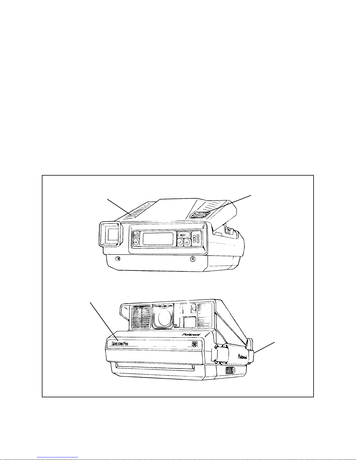
Spectra Pro/Image Pro/Minolta Pro External Physical Differences
Figure 1-2 illustrates the physical external differences between Spectra Pro/Image
Pro/Minolta Pro cameras and Spectra cameras:
• New top cover insert
• New S1/S10 button inlay
• New front decorative plate (with Spectra Pro/Image Pro/Minolta Pro name)
• New hand strap
T op Cover Insert
Front Decorative Plate
S1/S10
Button
Hand Strap
Figure 1-2. Spectra Pro/Image Pro/Minolta Pro external physical differences
8
Page 9

Sectiion 2 - Disassembly and Reassembly
Note: This section presents only the One Board Spectra Pro/Image Pro/Minolta Pro
camera disassembly and reassembly procedures that are different from those of
the Spectra camera. See Spectra Service Manual for all disassembly and
reassembly procedures not covered here.
Special Tools
Special T ools for Disassembly
• Hinge Pin Removal/Insertion Tool
P/N 13384 (for grasping Mid-Cover Hings Pins; See Figure 2-1)
• Square Socket T ool Bit with Handle
P/N 1 1913 (for removing screws holding LCD Board to Ranging Board;
see Figure 209)
Warning: Do not use the torque-limiting screwdriver to remove these screws.
Special T ools for Reassembly
• Torque-Limiting Screwdriver
P/N CR13397, with special Square Bit, P/N CR 13398 (for installing screws holding
LCD Board to Ranging Board; See Figure 2-9)
• Solder AideTool (green/black stick) P/N 942268
• Long needle-nose pliers with coated jaws
P/N 13186 (for reassembly of wire connectors use them to position the wire
connector with the pin connector, then use the Solder Aide Tool to press into position)
Warning: Do not use these pliers for disassembly.
9
Page 10
Cautions and Reminders
Use proper grounding to protect delicate CMOS circuitry from static discharge damage.
Avoid shock from the photoflash capacitor by discharging it with Dump Probe P/N
131 19 immediately after removing the Top Cover.
Handle flexes (Features Flex, Motor Gear Drive Flex) carefully to avoid crimping or
crarcking from sharp bends.
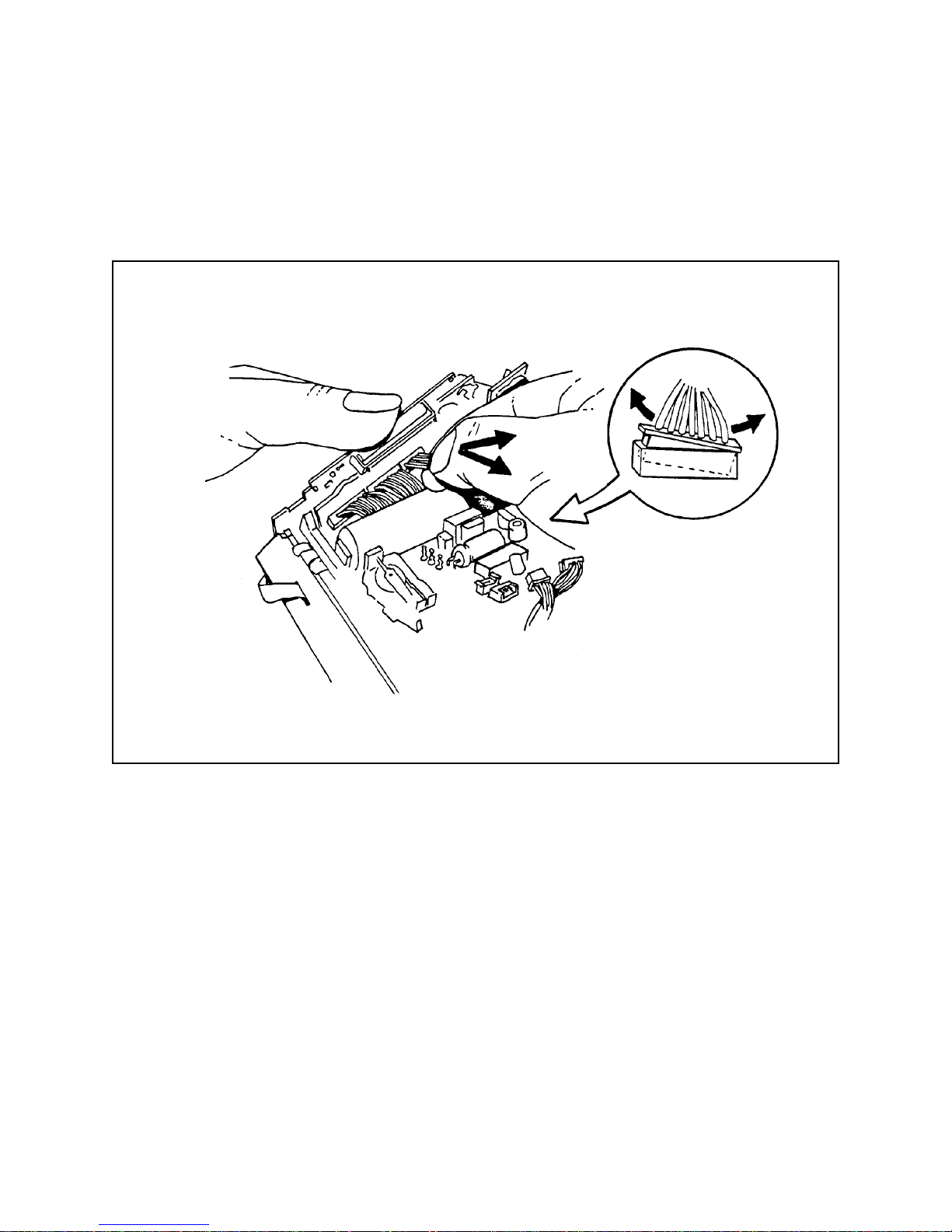
Remove wire connectors with fingers only . Do not use pliers or other tools. Carefully
grasp the wires near the connector betwen thumb and index finger and pull gently while
rocking the connector from side to side (Figure 2-1).
Figure 2-1. Proper removal of a typical wire connector
10
Page 11
Removing Mid-Cover
1. Remove the top cover as directed in Spectra Service Manual
2. With the special Hinge Pin Insertion/Removal Tool P/N 13384 (Figure 2-2), grasp the
hinge pins at the reduced diameter section and pull them toward the center line of the
camera to remove them.
3. Close the camera (if erected) and open the front door. Insert a soldering aide (green
stick) betwen the mid-cover and the side of the main frame, twisiting the greenstick
while holding the side of the mod-cover out. Then insert the greenstick on the
opposite side and pry outward.
4. Close the font door and lay the camera flat. Bend the sides out slightly, pivoting the
locating cutouts on the bottom cover. Then lift off the mod-cover.
Hinge Pin Removal/Insertion Tool (P/N 13384
Figure 2-2. Removing hinge pins and mid cover
Pull
Grasp
11
Page 12
Disassembling Mid-Cover
1. To remove the eye cup, use a greenstick to spring out the tabs on the eye wedge
retainer (Figure 2-3). Remove the clear plastic eye wedge. The eye cup can now be
removed from the eye wedge retainer.
2. To remove the five control panel buttons, insert the point of a greenstick in the center
of the button, and push the button out.
Note: When replacing buttons, be sure the markings are oriented correctly .
If they are not, the button cannot be inserted in the panel.
Eyecup
Control Panel Button
Tab
Eye Wedge
Tab
Greenstick
Figure 2-3. Removing eye cup and buttons from mid-cover
12
Page 13
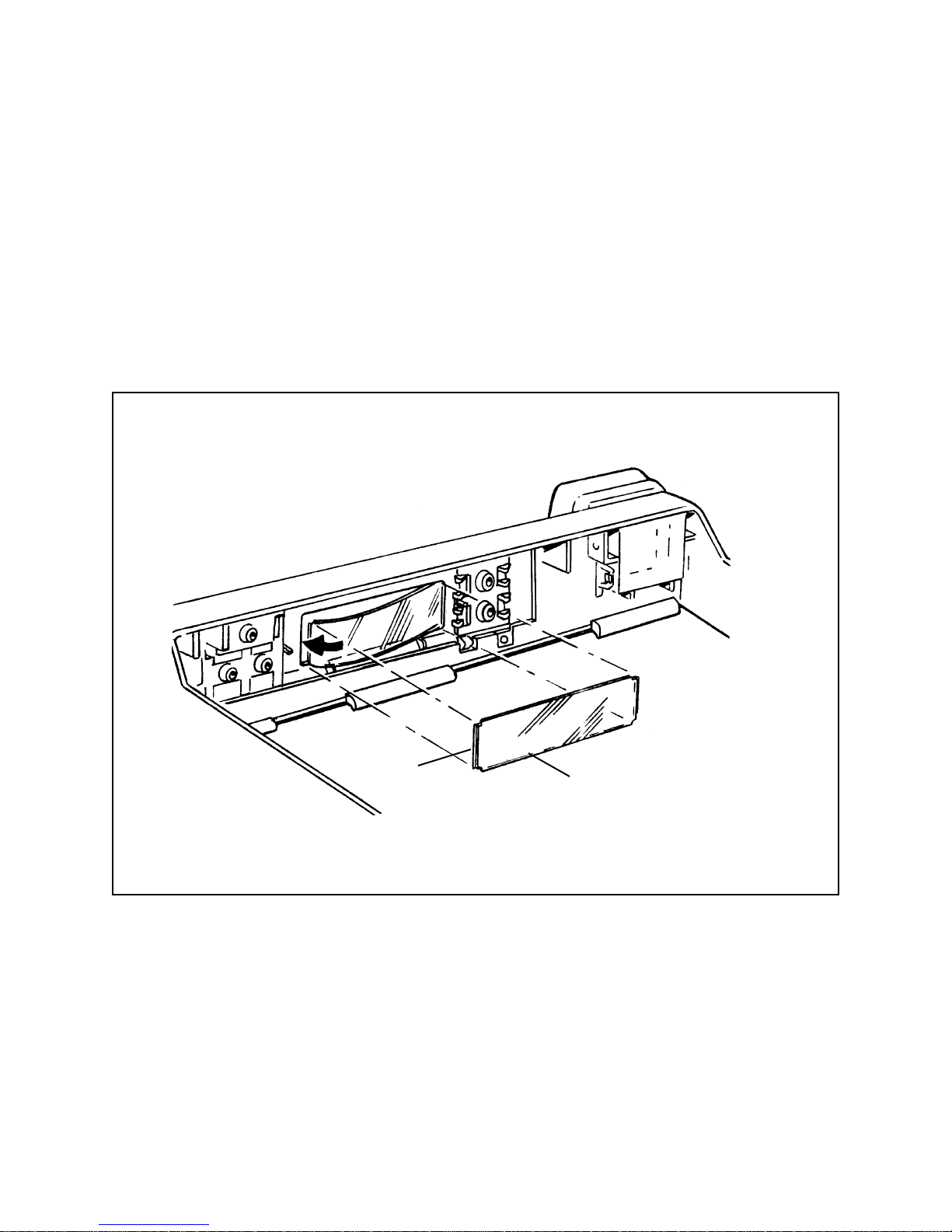
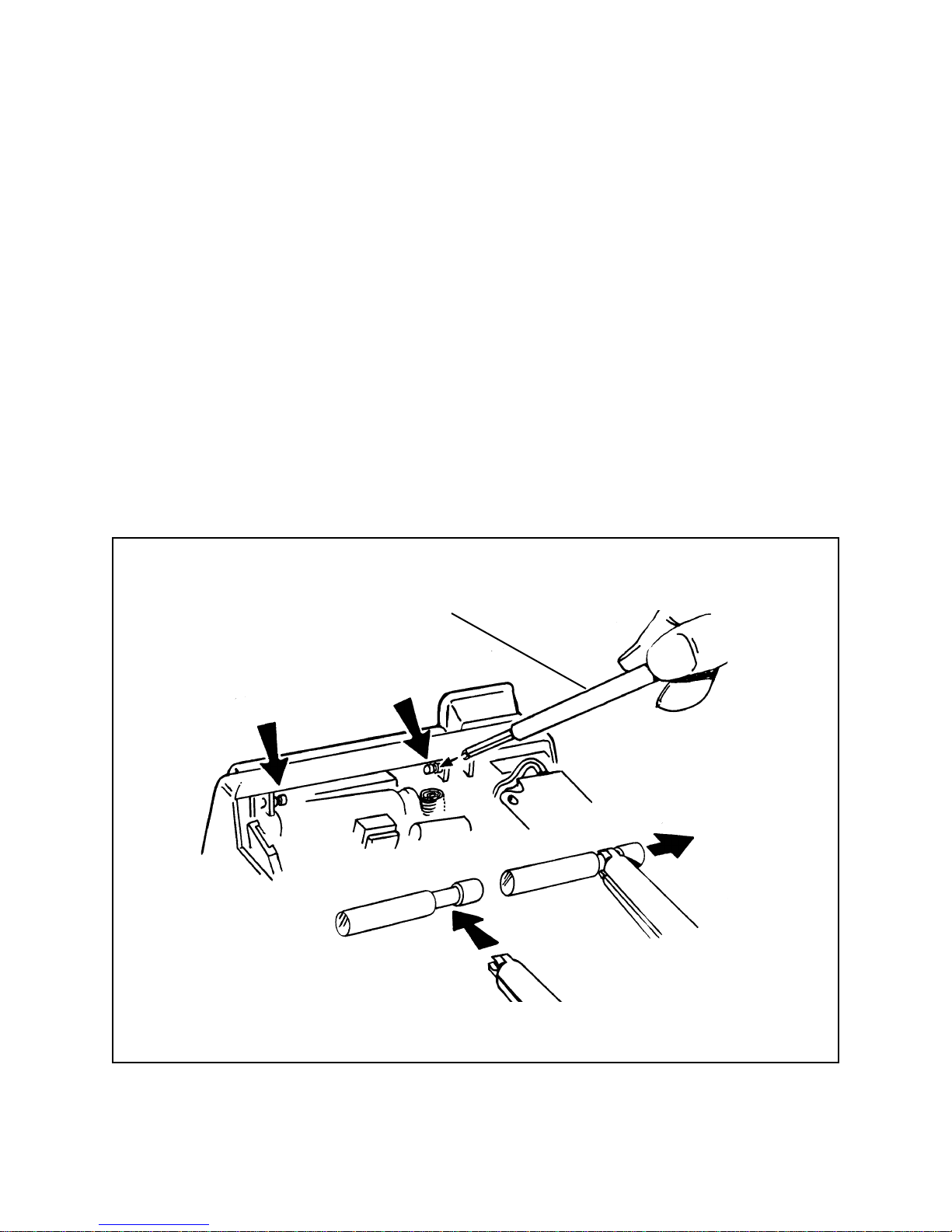
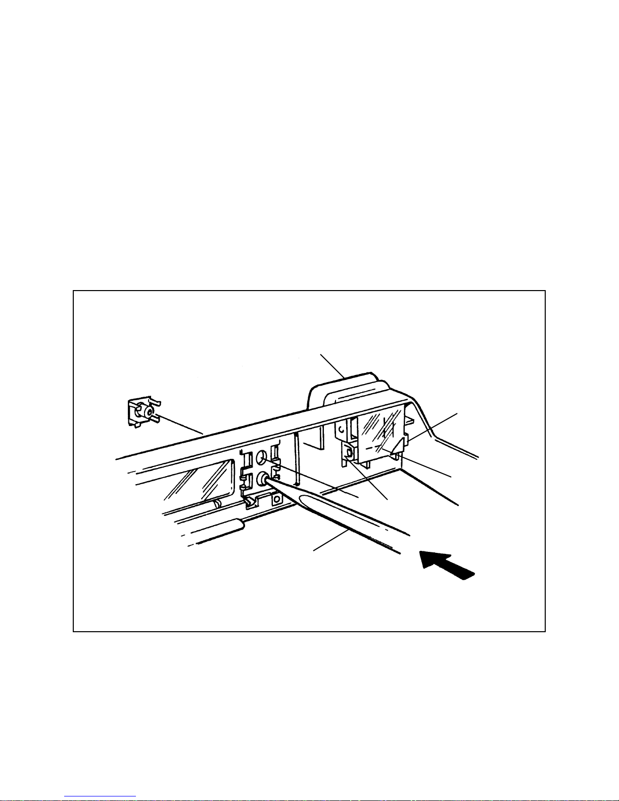
3. T o remove the LCD window (Figure 2-4), press it carefully from the outside, bowing
the window slightly to free the tab at the end. Lift it out of the mod-cover.
Note: When replacing the LCD window, insert the end nearest the viewfinder first.
Then bow the window slightly as shown and snap the other end into place.
4. To replace the font decorative plate, pry up the end with an Exacto knife and peel it
off. Make sure the knife does not slip and scratch the cover.
Figure 2-4. Removing LCD window from mid-cover
Tab
LCD Window
13
Page 14
Removing Ranging Board
Note: Be sure to note the position of all wires and wire connectors before you remove
any parts, then return them to their original positions upon reassembly .
1. Remove the top, mid and bottom covers.
2. Disengage the S10/S1 assembly from the spring tab.
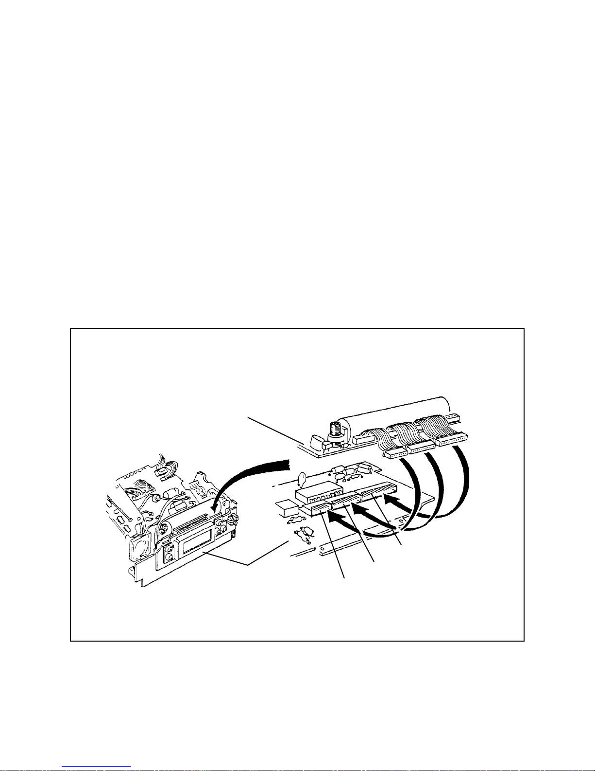
3. Disconnect the follwing wire connectors from the One Board Strobe/Exposure
Module Assembly; J7, J6, J4, J5. (See page 4-15 for locations.)
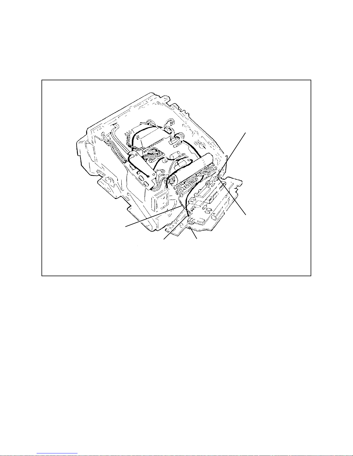
4. Lift the ranging board slightly to free it from the tabs at the bottom-rear of the main
frame and to gain access to connectors J9, J10 and J11 on the ranging board
(Figure 2-5).
J1
J2
One Board
Strobe/Exposure
Module
J3
Figure 2-5. Ranging board and connectors for J1, J2 and J3
Ranging
Board
J9
J10
J11
14
Page 15
5. Release connectors J1, J2 and J3 from the ranging board by grasping the wires
between your thumb and index finger and rocking the connector from side to side
(Figure 2-6).
Figure 2-6. Releasing connectors from ranging board
6. Release the white wire (J5) and the brown wire (J4) from the MiniSert self-locking
terminals on the ranging board (Figure 2-7).
7. Release the paired black/red transducer wires from connectors J1 and J20 on the
ranging board (Figure 2-7). Straighten out the bare ends of the wires bent back over
terminals J19 and J20. Then either: (a) pull the wires out of the terminals, or (b)
unsolder them and pull them out.
15
Page 16
8. Remove the ranging board (with the LCD board attached).
White Wire
to J5
Brown Wire
to J4
Ranging
Board
Black/Red Wire
to J20
Black Wire
to J19
Figure 2-7. Releasing ranging board wire connections
16
Page 17
Replacing Ranging Board
1. Reconnect the following wires to the ranging board (Figure 2-7) on previous page):
• White wire to self-locking terminal J5
• Brown wire to self-locking terminal J4
• Black trnsducer lead to terminal J19 (GND)
• Black/red lead to terminal J20
2. With needle-nose pliers, alighn the wire connector J1 (from the One Board
Strobe/Exposure Module Assembly) with the mating pin connector on the ranging
board (Figure 2-8), then press the wire connector into position with solder aide
tool 941168.
3. Using the same technique described in step 2, reconnect wire connectors J2 and J3
(from the One Board Strobe/Exposure Module Assembly) with their mating pin
connectors on the ranging board.
4. Place the ranging board in its normal position, with the projecting tabs on the main
frame in the notches at the bottom of the ranging board.
Solder Aide
Tool
Needle-Nose
Pliers
Figure 2-8. Reconnecting J1, J2 and J3 to ranging board
17
Page 18
Removing LCD Board from Ranging Board
1. Hold the camera vertically, with the front down.
2. Using Square Socket T ool Bit with Handle, P/N 11913, carefully remove the two
machine screws (A in Figure 2-9) securing the LCD board to the ranging board.
Hold the bracket (D in Figure 2-9) temporarily in place with your finger .
Warning: Do not use Torque Limiting Screwdriver, P/N CR 13397, to
remove the screws.
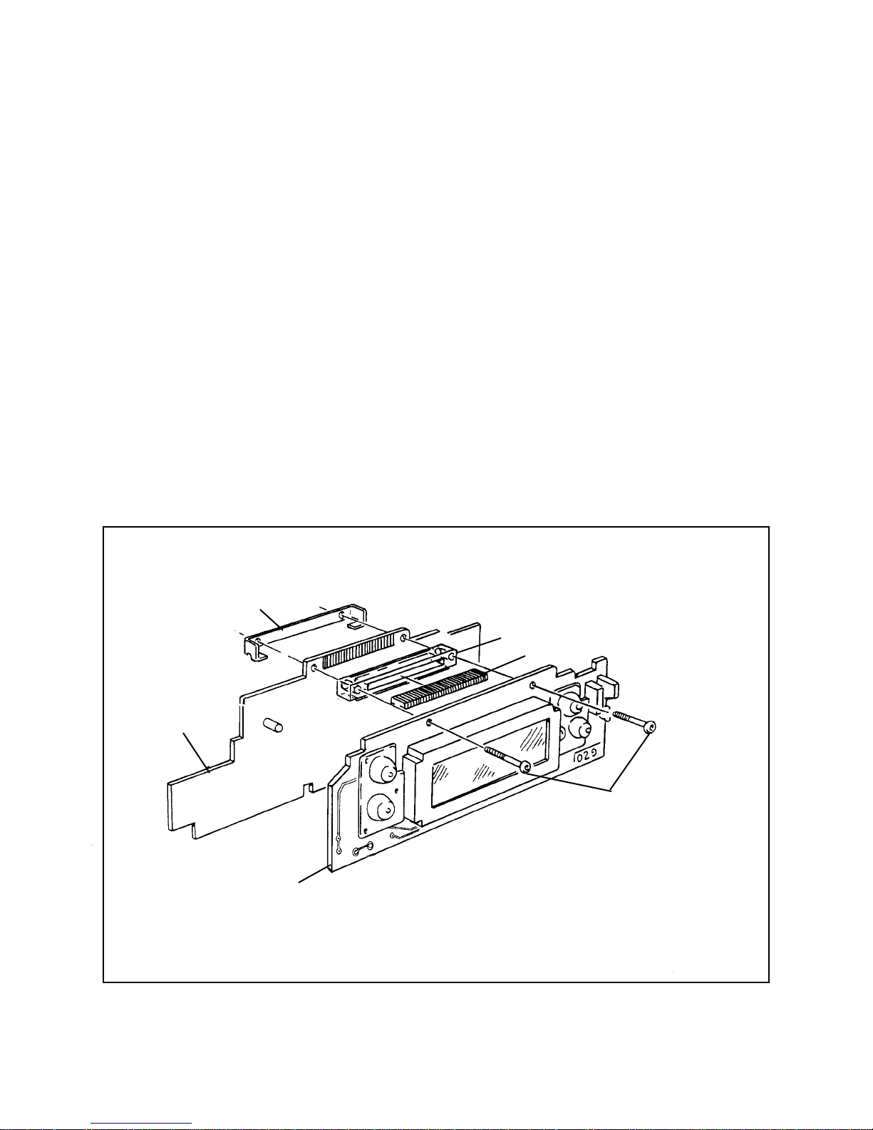
3. Carefully lift off the LCD board. Be careful not to lose the following parts, which are
released when the LCD board is removed:
• Clear plastic spacer block (C in Figure 2-9)
• Gold-colored elastomeric zebra connector (B in Figure 2-9)
• Metal retainer (D in Figure 2-9)
Ranging Board
D
C
B
A
Warning: Remove only with Square
Socket Toll Bitwith Handle (P/N 11913).
Do not use Torque Limiting Screwdriver.
LCD Board
Figure 2-9. Removing LCD board
18
Page 19
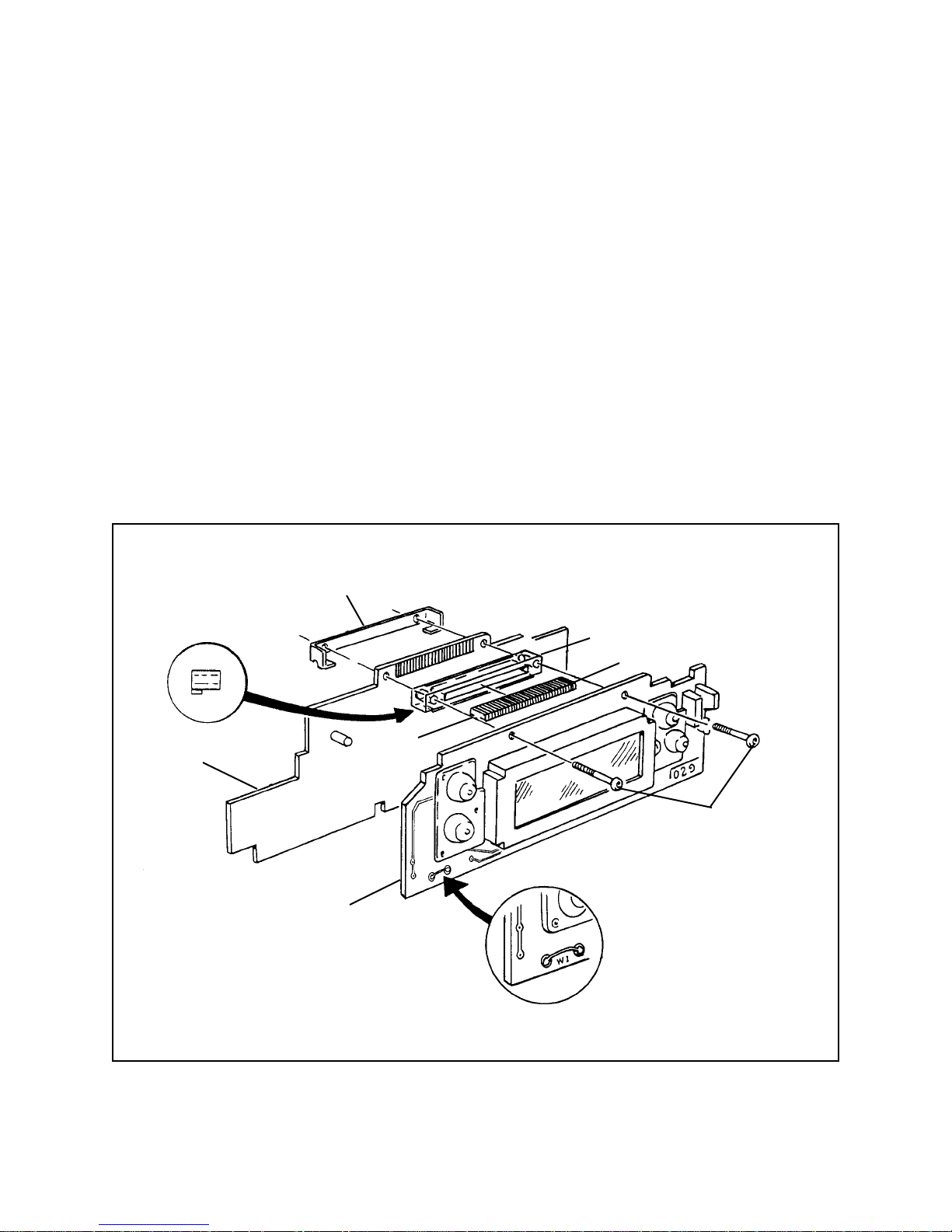
Reconnecting LCD Board to Ranging Board
1. Using your finger, hold the metal retainer ( D in Figure 2-10) in place behind the
ranging board.
2. Place the zebra connector (B in Figure 2-10) in the slot in the plastic spacer block
(C), concave side down.
3. Align the holes in spacer block (C) with the holes in the ranging board. Orient the
block as show, with the end notches facing down and the projecting shoulder in the
position shown.
4. Using Torque Limiting Screwdriver, P/N CR 13397, (factory-set for 8 oz-in.) with
Square Bit, P/N CR 13398, install the two mounting screws. Alternatively tighten
each one a small amount until you reach the se torque (screwdriver clutch slips).
D
Ranging Board
To display distance in metric units,
cut jumper w1.
C
B
Concave
Side
A
Warning: Install only with
Torque Limiting screwdriver
(P/N CR 13397) and Square Bit
(P/N CR 13398.
LCD Board
Figure 2-10. Replacing LCD board
19
Page 20
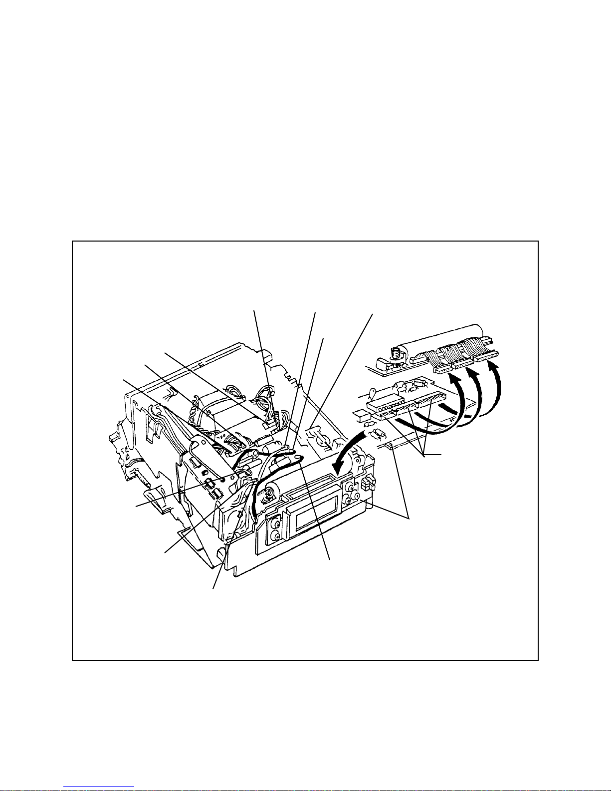
Removing One Board Strobe/Exposure Module Assembly
1. Remove the top cover, mid cover and bottom covers.
2. Disengage the S10/S1 assembly from the spring tab.
3. Push the S10/S1 assembly tab (Figure 2-11) to free it from the One Board
Strobe/ExposureModule Assembly .
Push Tab
to Free
S1/S10
Assembly
J4
J5
J6
J7
Red Wire
t0 J14
J26
Green Wire
to J17
White Wire
to Trigger
Coil (soldered)
Figure 2-11. Disconnecting one board strobe exposure module
J9, J10, J11
(Lift One
Board/Strobe
Exposure
Module
to access)
Ranging
Board
Black Wire
to J15
Orange Wiew
to J16
20
Page 21
4. Disconnect the following wires from the One Board Strobe/Exposure Module
Assembly (Figure 2-11):
• Black wire from J26
• Red wire from J14
• Black wire from J15
• Orange wire from J16
• Green wire from J17
5. Unsolder the white wire from the trigger coil (Figure 2-11)
6. Disconnect wire connectors J7, J6, J4, and J5 from the One Board Strobe/Exposure
Module Assembly .
7. Lift the One Board Strobe/Exposure Module Assembly to access wiring connectors
J9, J10, and J11 on the ranging board.
8. Release each of the three connectors (J1, J2, J3) from the ranging board
(Figure 2-11) by grasping each connector between your thumb and index finger
and lifting one side of the connector at a time.
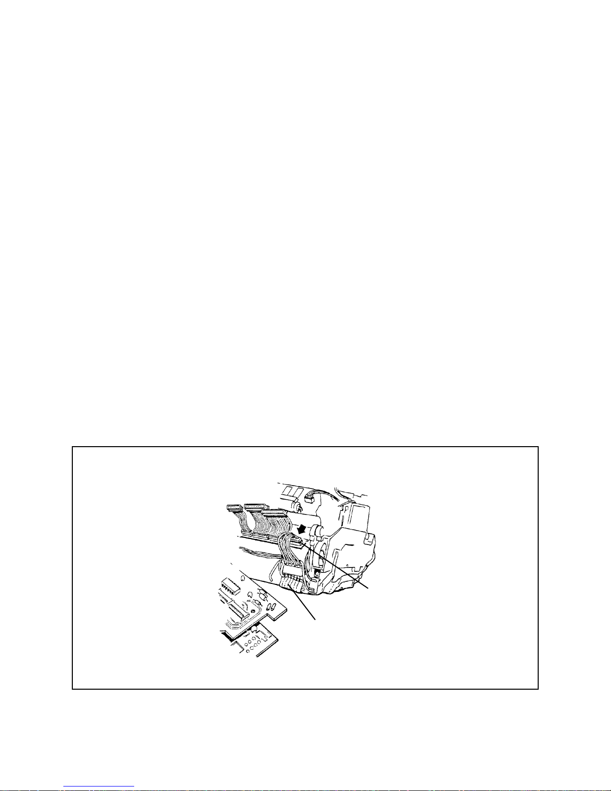
9. Release wire connector J8 (from the Wire/Motor Gear Drive Flex Assembly) from the
One Board Strobe/Exposure Module Assembly (Figure 2-12).
J8
Motor/Gear Drive
Flex assembly
Figure 2-12. Removing J8 from one board strobe/exposure module
21
Page 22
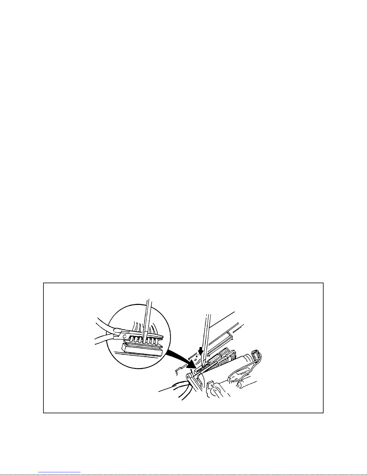
10.Use tweezes to remove the photodiode ratainer from the shutter base block
(Figure 2-13).
1 1.Lift out the One Board Strobe/Exposure Module Assembly.
Note: To install a One Board Strobe/Exposure Module Assembly, reverse this
procedure.
Shutter Baseblock
Photodiode Retainer
Figure 2-13. Removing photodiode retainer
22
Page 23

Section 3 - Testing and Adjustments
Spectra Pro/Image Pro/Minolta Pro System Functional T est
Purpose
The purpose of the functional test is to determine if the camera is operating properly
during various phases of simulated operation. In this test the camera is cycled through
dark slide, strobe exposures, non-strobe exposures, and end-of-pack. The intent is to
isolate problems for troubleshooting. If the camera does not operate as described
below , consult the troubleshooting chart most closely allied with the problem.
Equipment Required
• Film Pack Simulator #12467
• Film Pack Simulator Adapter #13130
• Power Supply - Power Mate #12531 or Lambda #12429
23
Page 24
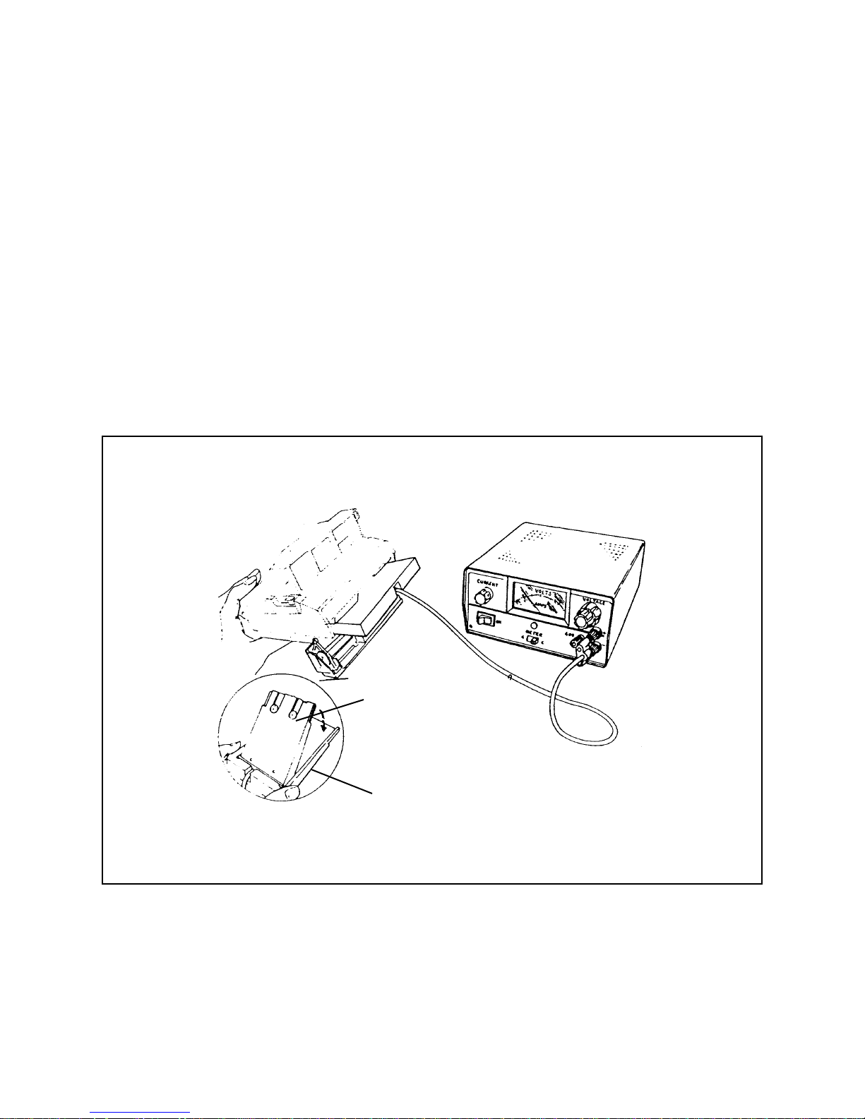
Test Setup
1. Insert the Film Pack Simulator Adapter #13130 onto the Film Pack Simulator #12467
(Figure 3-1).
2. Plug the Film Pack Simulator with adapter into the power supply (either Power Mate
#12531 or Lambda #12429).
3. Plug the power supply into a 110 VAC power source.
4. Turn the power supply ON.
5. Adjust the power supply output voltage to 6 VDC.
Figure 3-1. Setup for spectra pro/image pro/minolta pro functional test
Film Pack Simulator
#12467
Film Pack Simulator
Adapter #13130
24
Page 25

Test Procedure
1. Erect the camera and open the film door.
2. Install the film pack simulator with the adapter into the camera. The camera should
not cycle.
3. Remove the film pack simulator from the camera.
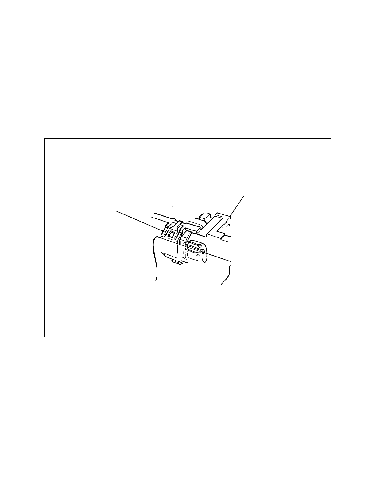
4. Using the tip of a solder aide, close the camera door latch (Figure 3-2).
Push in with soldering
aide (greenstick) to
close door latch.
Figure 3-2. Closing door latch
25
Page 26

5. Install the film pack simulator into the camera again. The camera should go through a
dark slide cycle with the following events happening:
• The strobe should not fire.
• The camera shutter blades should remain closed.
• The strobe charging light (red) should come on and then go off.
• The strobe ready light (green) should come on. (The green ready light will stay on
for approximately 30 seconds and will then extinguish if the camera is not used.)
• The LCD control panel should appear as shown in Figure 3-3.
Figure 3-3. LCD control panel at completion of dark slide
6. Aim the camera at an object less than one foot (.1 meter) away and press the
S1/S10 button halfway down (preview mode). The following should happen:
• A warning tone (beep! beep!) will sound.
• A flashing yellow triangle within a yellow square will be visible in the viewfinder.
• A red figure “1” will be visible in the viewfinder (USA cameras)
-OR- a red ”.1” will be visible in the viewfinder (non-USA cameras).
• The LCD panel will display “1.0 FT (USA cameras) -OR- will display “.1M”
(non-USA cameras).
26
Page 27

7. Aim the camera at an object exactly four feet (1.2 meters) away and press the
S1/S10 button down half way . The following should happen:
• A green circle within a green square will be visible in the viewfinder.
• A red figure “4” will be visible in the viewfinder (USA cameras) -OR-
a red figure “1.2” will be visible in the viewfinder (non-USA cameras).
• The LCD panel will display “4.0 FT” (USA cameras) -OR- the LCD panel will
display “1.2M” (non USA cameras).
8. Cover the transducer using the fingers or palm of your left hand (Figure 3-4) or you
can cover the transducer with photographic tape. Use care to prevent covering the
photocell. Press the S1/S1 button half way down. (This simulates an infinity
exposure.) The following should happen:
• No red figure should be visible in the viewfinder .
• The LCD panel will display “0 0 FT” (USA cameras) - OR- the LCD panel will
display ”0 0 M” (non USA cameras).
• Depending on the ambient light available, a flashing yellow triangle within a yellow
square (with warning beeps) or a green circle within a green square will be visible
in the viewfinder. The warning yellow triangle will appear in low light level
situations, while the green circle will appear if there is adequate light for a good
exposure.
27
Page 28

Cover transducer
with
hand or tape.
Do not
cover photocell
Figure 3-4. Covering transducer to simulate infinity exposure
9. Now, aim the camera at an object within the range of 2 feet (.6 meter) to 15 feet (4.5
meters) and press the S1/S10 button all the way. The following should happen:
• The strobe should fire.
• Y ou should hear the camera go through an exposure cycle. (The blades should
open and close, the Quintic lens should move, and the motor should run.)
• The LCD panel should change from 10 to 9 in the Frames Remaining area.
• The red strobe charging light should come on and then go off.
• The green strobe ready light should come on.
10.Repeat the previous step six more times and observe that the camera operates as
indicated above.
28
Page 29

11. Use the Mode button and either of the UP/DOWN buttons on the control panel to turn
the strobe switch off. (The bar under the strobe symbol disappears.) Turn the front
of the camera toward you. Cover the photocell with black photographic tape. Insert
a soldering aide between the flapper door and the bottom of the shutter (Figure 3-5).
12.With the camera aimed toward you, press the S1/S10 button all the way.
The following should happen:
• The warning beeps should sound.
• There should be no strobe fire.
• The moving Quintic frame should swing down below the level of the shutter during
the exposure and should be visible through the open flapper door as seen in
Figure 3-5. (This is the short distance Quintic position.)
• The shutter blades should open and stay open for the maximum time-out period
of 2.8 seconds.
• The camera motor should run.
• The Frames Remaining number on the LCD control panel should change from “3”
to “2”.
Strobe switch
in OFF position
Quintic lens moves
all the way down
Insert soldering aide in
far left side to hold
flapper door open
Figure 3-5. Quintic lens moves to short-distance setting
29
Page 30

13.Turn the autofocus feature off and set the distance to infinity as follows:
• Press the MODE button until only the autofocus symbol (AF) is visible in the LCD
display .
• Press the up or down arrow button to remove the bar from beneath the autofocus
symbol. The display will show either “5.0FT” or “1.6M”.
• Press the MODE button. The “5.0FT” or “1.6M” will begin to flash.
• Repeatedly press the down arrow button until the infinity symbol replaces either
“5.0FT” or “1.6M”.
• Press the MODE button to return to a full display .
If the flash or audio features need to be turned off, press the MODE button until
the symbol for the desired feature is displayed. Then press the up or down arrow
button to remove the bar from beneath the symbol. (No bar beneath the symbol
indicates thatthe feature is off.)
Note: The display automatically turns off after 30 seconds to conserve power.
To turn it on again, press the MODE button or the shutter button.
14.With the camera aimed toward you, press the S1/S10 button all the way. (The
photocell should remain covered with the black photographic tape and the soldering
aide should still be inserted into the flapper door area.) The following should happen:
• The warning beeps should sound.
• There should be no strobe fire.
• The moving Quintic lens frame should swing down below the level of the shutter
and should be visible through the open flapper door (Figure 3-6). This is the
infinity Quintic position.
• The shutter blades should open and stay open for the maximum time-out of 2.8
seconds.
• The camera motor should run.
• The Frames Remaining number should change from “2” to “1” on the LCD control
panel.
30
Page 31

15.Remove the soldering aide from the flapper door and remove the black photographic
tape from the photocell. Press the green A button on the control panel to return the
camera to its original settings.
AF switch in OFF setting
Quintic lens moves
down part way
Figure 3-6. Quintic lens moves to infinity setting
16.Press the self-timer button. The following should happen:
• The warning tones (beep! beep! should sound. The tones should get
progressively faster until two seconds before the exposure when the tone
becomes steady.
• At the front of the shutter, the red led next to the photocells should flash. The
flashing will get progressively faster until two seconds before the exposure when
the led stays on.
• At the end of 12 seconds, the strobe will fire and the camera will cycle.
• The Frames Remaining number on the LCD control panel will change from “1”
to “0”.
• The end of pack chimes will ring three time.
31
Page 32

17.Press the S1/S10 button all the way down. The following should happen:
• The end of pack chimes will sound three times.
• The strobe will fire.
• Release the S1/S10 button.
• The camera will cycle.
• The end of pack chimes will sound three times.
18.Look into the viewfinder and press the S1/S10 button half way down. The following
should happen:
• A flashing “0” will be visible in the viewfinder.
• The end of pack chimes will ring three times.
Note: If the S1/S10 switch is pressed all the way down with an empty film pack, the
strobe will fire. After the switch is released the camera will cycle. This is
normal.
This completes the functional test of the Spectra pro/Image Pro/Minolta Pro
camera. If the camera does not function as described, go the failure mode
section and refer to the chart which most closely corresponds to the malfunction.
32
Page 33

Star Tester Model 12650-3 Description
This Star Tester is an upgrade of the Model 12650-2 (for 600 Series and other
cameras). The 12650-3 permits testing Spectra System Cameras for seven different
exposure-and timing-related operating characteristics, as well as 600-Series and other
cameras.
Except for a new Horn (P/N 13146) for holding Spectra System Cameras and a few
name changes of Selector Switch positions, the 12650-3 Tester is outwardly identical to
the earlier Model 12650-2 Star Tester.
Model 12650-3 Controls and Indicators
Listed below are the Star Tester 12650 - 3 controls and indicators shown in Figure 3-7.
The integrating light sphere and electronics required to compute and display exposure,
timing and functional characteristics of the camera under test are all housed within the
Tester cabinet.
Figure 3-7
KEY CONTROL/INDICA T OR FUNCTION
1 Disc Position Lamps* Not used
2 Reset Button Clears electronics between tests
3 Disc/Ride Time Switch* Selects T est mode (7000 ZLS,
Flash Exposure, Ambient & Blade
Speed for Spectra camera.)
5 Horn Volts Selector Switch Selects 5V (low), 6V (nom) or
6.8V (high). Simulates film pack
battery voltage.
6 20V/2000V Selector With Volt Probe Jack and DC
Voltmeter , allows use of T ester as
voltmeter .
7 V olt Probe Jack For checking DC voltages in
camera under test, with standard
probe.
8 Timing Meter Digital readout of strobe recycle
time or blade speed.
9 DC V oltmeter Digital readout of circuit voltages;
also use with probe in Volt ProbeJack.
* Not used for testing Spectra cameras
33
Page 34

Figure 3-7
KEY CONTROL/INDICAT OR FUNCTION
10 Stops Error Meter Digital readout for Ambient,
Hybrid, Strobe Expos. T ests.
11 DC Current Meter Digital readout of energy req’d
to charge Strobe capacitor.
12 ZLS Meter Digital readout of strobe light
output in Zonal Lumen seconds.
13 Power Switch AC line voltage On/Off to T ester,
Lights when T ester is powered.
14 Pack Simulator Jack Connection for film pack
simulation voltage. Lets tester
function as a power supply.
15 Strobe Adaptors (two)* Aligns electronic flash of 600/680
camera under test to Star
T ester .
16 Horn Cable Connector Accepts plug on Horn cable.
17 Disc Detector Connector* Accepts cable from 600 Disc
Detect/Ride Time Fixture.
18 J4 Connector* For future applications.
19 T est Point Connectors For connections to oscilloscope.
Also used for calibrating T ester.
* Not used for testing Spectra cameras
Caution: When the tester is not in constant use, turn the
selector switch to 7000 ZLS. This reduces light
source wear and keeps the tester in a neutral state,
ready for immediate resumption of testing.
34
Page 35

Figure 3-7. Star tester 12650-3 controls and indicators (see text for descriptions)
35
Page 36

Star Tester Setup and Pre-Test Checks
Star Tester Setup
1. Install Tester on level surface with clear area around Tester to allow sufficient air flow
for cooling.
2. Locate the Tester on a bench or table so that when the Spectra on its Horn is placed
on the top of the Tester, the Spectra lens will be exactly 4.5 feet (135 cm) from a
graywall target. Also, be sure that the front of the camera is parallel to the graywall
(or the long axis of the camera, front to back, is at right angles to the graywall
Figure 3-8).
3. Be sure that the area between camera and graywall, for a width of approximately 4
feet (or what can be seen in the Spectra viewfinder), is clear of any objects. This will
prevent erroneous readings caused by reflections from the sonar side lobes of the
Spectra camera.
Figure 3-8. Locating star tester in relation to graywall target
36
Page 37

Pre-Test Checks
1. Connect the Tester to 115 VAC, 50/60 Hz line.
2. Mount the camera on the Spectra Horn (P/N 13146) and connect the cable from Horn
to the receptacle marked “Horn” (key #16 in Figure 3-7) on the right side of theTester.
3. Turn the Tester Power Switch ON (switch will illuminate if the Tester is receiving
power). Let the Tester warm up a minimum of 10 minutes before performing tests.
4. Open the Front Door of the Spectra camera and with a greenstick (solder aid tool),
trip the Door Switch into DOWN position (Figure 3-9).
5. Position the Horn with the camera mounted on it against the front of the Tester, with
the guide tab on the right side of the Horn against right edge of window mounting
plate (Figure 3-10).
6. Fully depress the camera Shutter Button five times. Read the Stops Error Meter and
check the Spectra Specification for agreement.
7. AT LEAST WEEKLY: Using a Standard Spectra camera as a reference, perform the
Ambient Exposure Test to check that the Star Tester is operating properly.
Figure 3-9. Tripping spectra system door switch to DOWN position
37
Page 38

Guide T ab
Figure 3-10. Positioning camera on horn against star tester
38
Page 39

Order of Spectra Pro/Image Pro/Minolta Pro System T ests
Tests on Spectra Pro/Image Pro cameras should be performed as described below.
Mandatory Tests
Perform the following tests in the order shown on all cameras:
1. Ambient Exposure at 100 C/FS.
2. Strobe Exposure (Graywall).
Strobe Exposure Test Reading Cannot be Corrected
via IR Exposure Calibration Slide
If the Strobe Exposure (Graywall) test reading is out of specification and cannot be
corrected by adjusting the IR Exposure Calibration Slide, follow the steps below:
1. Perform the ZLS Graywall Test.
• If the ZLS Graywall Test result is not within spec, replace the Strobe Board or the
Flashtube Assembly as required.
• If the ZLS Graywall Test is now within spec but the Strobe Exposure (Graywall)
reading remains out-of-spec, go to step 2.
2. Perform the Hybrid (ZLS/Blade Speed) Test.
• If the Hybrid Test reading is within spec but the Strobe Exposure test reading
remains out of spec, replace the exposure flex and retest.
• If the Hybrid Test reading is out-of-spec, perform the Hybrid Adjustment
(Opening Blade Spring). If this adjustment brings the reading within
specification, discontinue testing. If the adjustment fails to bring the reading
within specification, go to step 3.
39
Page 40

3. Perform the Blade Speed Test.
• If the Blade Speed is within spec but the Strobe Exposure Test reading remains
out of spec, replace the exposure flex and retest.
• If the Blade Speed Test reading is not within spec, perform the Blade Speed
Adjustment. If the Blade Speed Adjustment does not correct Blade Speed,
repair the Shutter Assembly and retest.
Excessive Battery Drain
If battery drain is excessive, perform the Strobe Integrated Current Test. If this reading
is out of spec, replace the strobe board.
Long Strobe Recharge Time
If the Strobe takes too long to recharge, perform the Strobe Charge Time Test. If the
reading is out of spec, replace the strobe board.
40
Page 41

Ambient Exposure T est
Purpose
This Test measures the energy on the film plane during an ambient (visible) light
exposure. The Star Tester light integrating sphere provides a constant scene
brightness level of 100 candles/ft2.
Test Setup
1. Trip the Door Switch on the camera into the down position.
2. Place the camera on the Horn against the Tester window.
3. Use the following steps to turn OFF the Autofocus, Flash, Audio and Exposure
Adjustment functions:
• Press the MODE button until only the auto focus symbol (AF) is visible in the LCD
display. Then press the up or down arrow button to remove the bar from beneath
theautofocus symbol. (no bar indicates that the feature is off.) Press the MODE
button twice to return to a full display.
• Press the MODE button until the symbol for flash is displayed. Then press the up
or down arrow button to remove the bar from beneath the symbol. Press the
MODE button once to return to a full display.
• Press the MODE button until the symbol for audio is displayed. Then press the up
or down arrow button to remove the bar from beneath the symbol. Press the
MODE button once to return to a full display.
• Press the MODE button until the symbol for the Exposure Adjustment function is
displayed. Then press the up or down arrow button to remove the bar from
beneath the symbol. Press the MODE button once to return to a full display
(Figure 3-11).
41
Page 42

Figure 3-11. Display for flash, autofocus, audio and exposure adjust OFF
Note: The display automatically turns off after 30 seconds to conserve power.
To turn it on again, press the MODE button or the shutter button.
4. Leave the Photocell on the camera uncovered.
5. Set the Test Selector Switch to AMBIENT.
Test Procedure
1. Press the Shutter Button fully and record the Stops Error Meter reading. Compare
the reading to the Specification.
2. Repeat the process two more times, recording all readings.
3. If the readings are within spec, proceed to the Strobe Exposure (Graywall) Test.
4. If the test readings are not within Spec, adjust the Ambient Exposure Calibration Slide
and retest. If reading is now within spec, proceed to Strobe Exposure (Graywall)
Test below.
5. If adjustment fails to bring the reading within spec, verify the following:
• The green ambient filter is in the proper position.
• The photocell cap is in position.
• The photocell is seated in the base block.
6. If the above steps do not bring the Ambient Exposure reading within spec, replace the
Exposure Flex and/or the Shutter Assembly and retest.
42
Page 43

Strobe Exposure (Graywall) T est
Purpose
This Test measures the resultant energy on the film plane during a 4.5 - foot (135 cm)
graywall exposure.
Test Setup
1. Trip the Door Switch on the camera into the down position.
2. Place the camera on the Horn on top of the Tester, with the lens 4.5” from the
graywall. The front of the camera must be parallel to the graywall, and the area
visible in the viewfinder must be clear of objects.
3. Make sure the Flash and Autofocus features are ON (bar displayed below each
symbol), and Audio and Exposure Adjustment are OFF (no bar). The display should
be as shown in Figure 3-12.
To turn a function ON or OFF, press MODE button until only the desired symbol is
displayed. Then press up or down arrow buttons to insert bar (turn ON) or delete bar
(turn OFF the function). To return to the full display, press MODE.
Note: The display automatically turns off after 30 seconds. To bring it back, press
either the MODE or Shutter button.
Figure 3-12. Display for flash and autofocus ON, audio and exposure adjust OFF
4. Leave the Photocell on the camera uncovered.
5. Set the Test Selector Switch to FLASH EXPOSURE.
43
Page 44

T
est Procedure
1. Press Shutter Button fully and note reading on the Stops Error Meter.
2. Repeat the procedure two more times, noting the Stops Error Meter readings.
Compare the readings to the Specification
3. If the test readings are not within Spec, adjust IR Strobe Exposure Calibration Slide
and retest.
4. If adjusting the IR Calibration Slide fails to bring the Strobe Exposure Test reading
within spec verify the following:
• The IR black filter is seated
• The photocell is seated in the base block
• The photocell cap is seated properly.
• If the above steps do not bring the Strobe Exposure (Graywall) reading within
spec, proceed to the LS Graywall Test.
44
Page 45

ZLS (Zonal Lumen Seconds) Graywall T est
Purpose
This Test measures the maximum strobe output. This is done by measuring the energy
on the film plane during a 4.5 foot (135 cm) graywall exposure with the shutter blades
fully open.
Test Setup
1. Trip the Door Switch on the camera into the down position.
2. Place the camera on the Horn on top of the Tester, with the lens 4.5” from the
graywall. The front of the camera must be parallel to the graywall, and the area
visible in the viewfinder must be clear of objects.
3. Flash should be ON (bar below symbol), and all other functions should be OFF (no
bar) as shown in Figure 3-13.
Figure 3-13. Display for flash ON, all other functions OFF
If necessary, turn the appropriate features on or off as follows:
• To turn flash ON: Press the MODE button until the symbol for flash is displayed.
Then press the up or down arrow button to display a bar under the symbol.
Press MODE once to return to full display.
• T o turn autofocus OFF: Press MODE until only the autofocus symbol is visible in
theLCD display. Then press the up or down arrow to remove the bar from
beneath the autofocus symbol. (No bar indicates that the feature is off.)
Press MODE twice to return to a full display.
• To turn audio OFF: Press the MODE button until the symbol for audio is
displayed. Then press the up or down arrow button to remove the bar from
beneath the symbol. Press the MODE button once to return to a full display.
45
Page 46

• To turn exposure adjustment OFF: Press the MODE button until the symbol for
theExposure Adjustment function is displayed. Then press the up or down arrow
button to remove the bar from beneath the symbol. Press the MODE button once
to return to a full display.
4. Cover the Photocell.
5. Set the Test Selector Switch to 7000 ZLS.
Test Procedure
1. Press the Shutter Button fully and note the reading on the ZLS Meter. Compare the
reading to the Specification.
2. If the ZLS Test reading is out of Specification, replace either the Flashtube Assembly
or the Strobe Board and retest.
3. If the ZLS Test reading is within specification but the Strobe Exposure (Graywall)
reading is still out of spec, perform the hybrid Test below.
46
Page 47

Hybrid (ZLS/Blade Speed) T est
Purpose
This Test measures the resultant energy on the film plane from full strobe output through
partially open blades, to determine whether the blades open at the proper speed and the
strobe fires at the proper time. If the results of this test are satisfactory, it means that
maximum strobe output, blade speed and ranging are all functioning properly .
Test Setup
1. Trip the Door Switch on the camera into the down position.
2. Place the camera on the Horn on top of the Tester, with the lens 4.5 ft. from the
graywall. The front of the camera must be parallel to the graywall and the area
visible in the viewfinder must be clear of objects.
3. Turn ON the Flash and Autofocus (bar under each symbol), and turn OFF the Audio
(no bar) so the display is as shown in Figure 3-14.
If necessary, turn the features on or off as follows:
• Press MODE until only the desired symbol is visible in the display . Then press
the up or down arrow to turn the feature on or off. (A bar under the symbol
indicates ON.)
• Press MODE to return to a full display.
4. Cover the Photocell.
5. Set the Test Selector Switch to 7000 ZLS.
Figure 3-14. Display for flash and autofocus ON, all other features OFF
47
Page 48

Test Procedure
1. Press the Shutter Button fully and note the reading on the ZLS Meter.
2. Repeat the procedure two more times, noting each Meter reading. Compare the
readings to the Specification.
3. If the test readings are not within Spec, perform the Hybrid Adjustment procedure
and retest.
4. If this adjustment does not bring the Hybrid T est reading within specification, proceed
to the Blade Speed Test below.
5. If the Hybrid Test reading is within spec but the Strobe Exposure Test reading is still
out of spec, replace the Exposure Flex and retest.
48
Page 49

Blade Speed Test
Purpose
This Test measures the time between first light detection and 95% blade opening.
Test Setup
1. Trip the Door Switch on the camera into the down position
2. Place the camera on the Horn against the Tester window.
3. Turn OFF the Flash, Autofocus and Audio functions. The display should be as shown
in Figure 3-15.
If necessary, turn the features on or off as follows:
• Press MODE until only the desired symbol is visible in the display . Then press
the up or down arrow to turn the feature on or off. (A bar under the symbol
indicates ON.)
• Press MODE to return to a full display . (If you are turning Autofocus OFF, you
must press the MODE button twice to return to a full display.)
4. Cover the Photocell.
5. Set the Test Selector Switch to BLADE SPEED.
Figure 3-15. Display for flash, autofocus and audio OFF
49
Page 50

Test Procedure
1. Push the Reset button on the Tester, then depress the Shutter Button. Disregard the
meter reading (this sets up Tester circuitry).
2. Press the Shutter Button again and watch the Timing Meter carefully. Note the
reading that remains constant for two seconds. Compare this reading to the
Specification.
3. If the reading is not within spec, adjust the blade speed (page 3-30) and retest the
camera.
4. If the adjustment did not bring the Blade Speed within specification, repair or replace
the Shutter Assembly and retest.
5. If Blade Speed is now within specification but Strobe Exposure is still out of spec,
replace the Exposure Flex and retest.
Spectra Pro/Image Pro/Minolta Pro Star Tester Specifications
Covered Ambient: -.1- to +.30 stops
(Install T est Cover on
camera for test purposes)
Covered Strobe Exposure -.30 to +.2- stops
(Graywall):
The following additional tests are required only if the Strobe Exposure (Graywall) cannot
be corrected by adjusting the IR exposure calibration slide. See page 3-14 of the
Spectra Camera Service Manual.
ZLS Graywall: 230 ZLS to 350 ZLS
Hybrid: (60 ZLS to 110 ZLS)
Blade Speed: 20 to 24 ms
50
Page 51

Ambient Exposure Calibration Slide Adjustment
1. Remove the Top Cover from the camera (Figure 3-16).
Warning: HIGH VOLTAGE EXPOSURE! Up to 320V is
present on top flash tube terminal (green wire)
and at various other locations on the strobe board.
Figure 3-16. Removing top cover from camera (see Section 2 for details)
2. If the Ambient Exposure Test readings are too low, use a dental pick and slide the
Ambient Calibration Slide (Figure 3-17) to the right in proportion to the amount the
reading is too low. The Ambient Calibration Slide is the one next to the Shutter Base
Block (rear most Slide, when Base Block is viewed from the rear of the camera).
3. If the Ambient Exposure Test readings are too high, slide the Ambient Calibration
slide to the left, in proportion of the amount the reading is too high.
4. Put the Test Top Cover in place and retest the camera. Readjust the Ambient
Calibration Slide if necessary .
51
Page 52

5. When the Ambient Exposure Test reading is within specification, replace the Test Top
Cover with the camera’s own Top Cover.
Note: If adjusting the Ambient Calibration Slide fails to bring the readings within
specification, refer to Steps 4, 5 and 6 of the Ambient Exposure Test
procedure.
Ambient
Calibration Slide
Figure 3-17. Adjusting ambient (visible light) calibration slide
52
Page 53

IR Strobe Exposure Calibration Slide Adjustment
1. Remove the Top Cover from the camera (Figure 3-16).
Warning: HIGH VOLT AGE EXPOSURE! Up to 320V
is present on top flash tube terminal (green
wire) and at various other locations on the
strobe board.
2. If the Strobe Exposure Test readings are too low, use a dental pick and slide the IR
strobe Exposure Calibration Slide (Figure 3-18) to the right, in proportion to the
amount the reading is too low. The IR Strobe Exposure Calibration Slide is the
nearer or front-most Slide, when the Base Block is viewed from the rear of the
camera).
3. If the Strobe Exposure Test readings are too high, slide the IR Calibration Slide to the
left, in proportion to the amount the reading is too high.
IR Strobe
Calibration Slide
Figure 3-18. Adjusting the IR strobe exposure calibration slide
53
Page 54

4. Put the Test Top Cover in place and retest the camera. Readjust the IR Strobe
Exposure Calibration Slide if necessary, using the Test Top Cover.
5. When the Strobe Exposure Test reading is within specification, replace the Test Top
Cover with the camera’s own Top Cover.
Note: If adjusting the IR Calibration Slide fails to bring the Strobe Exposure Test
reading within specification, refer to steps 4 and 5 of the Strobe Exposure
(Graywall) Test.
54
Page 55

Hybrid Adjustment (Opening Blade Spring)
1. Remove the Top Cover from the camera (Figure 3-16).
Warning: HIGH VOLT AGE EXPOSURE! Up to 320V
is present on top flash tube terminal (green wire)
and at various other locations on the strobe board.
2. If the Hybrid (ZLS/Blade Speed) Test readings are too low , increase the tension on
the Opening Blade Spring (Figure 3-19) by moving it one notch to the right (when
facing the back of the camera).
3. If the Hybrid T est readings are too high, decrease the tension on the Opening Blade
Spring by moving it one notch to the left (when facing the back of the camera).
4. Put the Test Top Cover on the camera and retest. Repeat the procedure, if
necessary, moving the Opening Blade Spring one notch at a time and replacing the
Test Top Cover each time before retesting.
5. When the Hybrid T est Reading is within specification, replace the Test Top Cover with
the camera’s own Top Cover.
Note: If changing the tension of the Opening Blade Spring fails to bring the
readings into the specification, refer to steps 4 and 5 of the
Hybrid (ZLS/Blade Speed) Test.
Change position of spring
in rack to change blade speed
Decrease Speeds
Increase Speeds
Figure 3-19. Hybrid adjustment (opening blade spring tension adjustment)
55
Page 56

Blade Speed Adjustment (Opening Blade Spring)
1. Remove the Top Cover from the camera (Figure 3-16).
Warning: HIGH VOLT AGE EXPOSURE! Up to 320V
is present on top flash tube terminal (green wire)
and at various other locations on the strobe board.
2. Using tweezers, carefully lift the upper end of the Opening Blade
Spring out of its
notch in the Shutter Base Block (Figure 3-19).
Caution: Do not overstretch spring!
3. If the Blade Speed is too slow, reposition the Opening Blade Spring one notch to the
right (when camera is viewed from the rear). If the speed is too fast, reposition the
Spring one notch to the left.
4. Put the T est Top Cover on the camera and retest Blade Speed. Readjust the
Spring position of necessary .
5. When the Blade Speed is within specification, replace the Test Top Cover with
camera’s own Top Cover.
6. If adjusting the Spring position will not bring the Blade Speed within specification,
replace the Spring and retest.
7. If the Blade Speed is still out of specification, disassemble the camera to the shutter
level (See the Disassembly/Reassembly Section of the Manual). Examine the
blade-opening parts. (Walking Beam/Inertia Assembly , Drive Link, etc.) and the
Shutter Blades for dirt, binding parts and damage. Correct any problems found,
reassemble the camera and retest the Blade Speed. Readjust the Opening Blade
Spring if necessary.
56
Page 57

Solenoid 1 Adjustment for Quintic Position
If the movable Quintic lens element travels at too high or too low a speed, its final
(focused) position may not be correct for the distance measured by the camera’s
sonar system. (If the Quintic moves too fast, for example, the Catch Pawl may not
be able to stop it at the correct position.)
Quintic speed can be adjusted as follows:
1. Remove the Top Cover from the camera (Figure 3-15).
Warning: HIGH VOLT AGE EXPOSURE! Up to 320V
is present on top flash tube terminal (green wire)
and at various other locations on the strobe board.
2. Using a small screwdriver , carefully turn the adjusting screw of Solenoid 1
(Figure 3-20) one-half turn at a time. Turn the screw counter-clockwise to increase
Quintic speed, clockwise to decrease Quintic speed.
3. Put the Test Top Cover in place on the camera.
4. Retest the camera to verify that the Catch Pawl catches (stops) the Quintic at the
correct position. If it does not, readjust the Solenoid 1 adjusting screw, one-half turn
at a time, until the Quintic is caught by the Catch Pawl.
5. When the proper Quintic catch is achieved, replace the Test Top Cover with the
camera’s own Top Cover.
6. If steps 1-3 fail to produce correct Quintic catch, disassemble the camera to the
shutter level and inspect the plunger of Solenoid 1, the Catch Pawl and the Quintic
element for dirt, damage, binding, etc. Correct any problems that are found,
reassemble the shutter and retest the camera.
57
Page 58

To increase Quintic speed,
turn screw CCW
T o decrease Quintic speed,
turn screw CW
Solenoid 1
Adjusting Screw
Figure 3-20. Adjusting solenoid 1 to change quintic speed
58
Page 59

Section 4 - Troubleshooting
Basic Requirements and Guidelines
Spectra Camera Familiarity
Before troubleshooting Spectra Pro/Image Pro Cameras, you should have received
training in Spectra servicing methods, have read the Spectra Service Manual, and know
how to use the Spectra Troubleshooting Charts.
Use of Logic Probe Model PRB-50
Follow all safety precautions and know the correct procedure and switch settings for
using this Probe, as described on the first page of the Spectra Troubleshooting Charts.
Pictorial and Schematic Diagrams
For convenient reference during troubleshooting, a pictorial and schematic diagrams of
the camera are included in this section. The pictorial identifies all test points and signal
paths.
Glossary of Abbreviations and Numbered Index
Abbreviations such as “RM “ (Ranging Module), “EM” (Exposure Module), etc., used in the
operating problem descriptions, are defined at the beginning of this section. Also, the
Operating Problems are listed in the approximate order of camera operation, and for
convenient reference, are numbered and indexed at the beginning of the section.
Basic Troubleshooting Approach
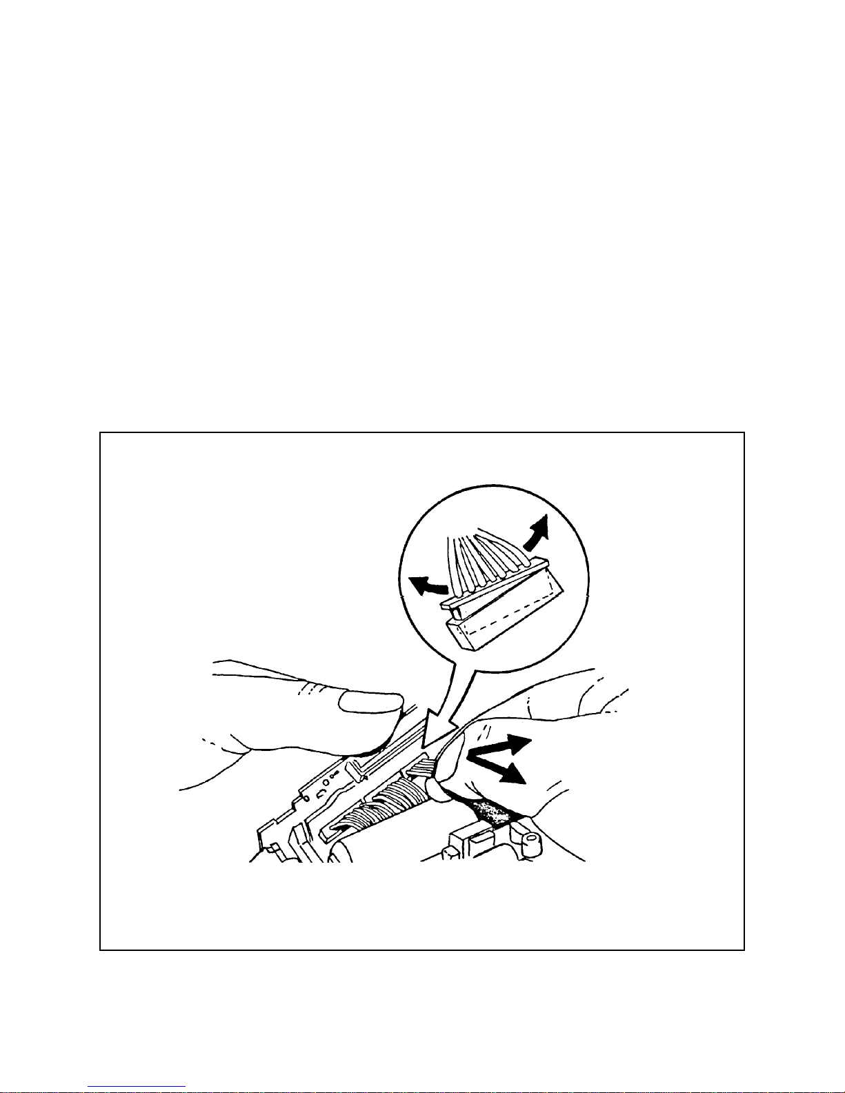
At the start, look for the obvious causes of a problem first: most occur at connections
points between the Exposure Flex and the Burndy connectors on the Ranging Board (Figure 4-1). Common causes of problems include:
• Wire connectors not completely pressed into pin connectors
• Contamination on the elastomeric (“zebra”) connector fingers
• Damaged elastomer in the “zebra” connector (Figure 4-2)
• Solenoids are not connected
• Encoder wires are not connected
• FEAT-TP (brown) wire is not connected, or is crossed with VBATT
(white) wire (see schematics)
59
Page 60

J1
J2
One Board
J3
Strobe/Exposure
Module
Ranging
Board
Figure 4-1. One board strobe/exposure module connections on ranging board
Elastomer
Figure 4-2. Elastomeric “Zebra” connector
Gold Contact
Fingers
60
Page 61

Intermittent Problems
Intermittent problems are typically caused by open circuits, resulting from a cold solder
joint, contamination (dirt, oil, oxide, etc.) on a connector pad, a loose connection, broken
street from a sharp fold in a flex, or a partially seated connector .
For intermittent failures involving the Ranging and LCD Boards, Figure 4-3 shows initial
“quick check” tests.
LCD to Ranging Module
Continuity Check
Good
Check Continuity:
Ranging Module to Rest of Camera
Good
Remove LCD Board and Elastomer
• Inspect Gold Fingers & Elastomer
• Check Finger Alignment: LCD to
Ranging Module
• Attach Known Good LCD and
Connector. Retest Camera.
Bad
• Lift Ranging Module: Check
Continuity
• Examine Burndy Connectors for
Cold Solder Joints & Shorts.
• Analyze Rest of Camera.
Bad
Bad
Loosen & Retighten Screws
Retest
Bad
Good
Original LCD or Connector
failure:
• Change LCD Board & retest
• Change elastomer & retest.
Figure 4-3. Initial test procedure for ranging board and LCD board
61
Page 62

Abbreviations Used in This Section
ONEBD One Board Strobe/Exposure Module
FM Features Module
RM Ranging Module
B+ Battery
EOP End of Pack
EOC End of Cycle
SPD Film Speed
VER Erect Voltage
SOL 1 Solenoid #1
SOL 2 Solenoid #2
STROBE Strobe Board
LCD Liquid Crystal Display Module
BB Camera Base Block
62
Page 63

Operating Problems and Typical Causes
T ypical causes of these operating problems are listed on the following pages:
Problem Page
No Dark Slide 4 - 6
Incomplete Dark Slide 4 - 6
Blades don’t Open 4 - 7
No S1 Cycle 4 - 7
Sticky S1/S10 4 - 7
Sensitive S1 4 - 8
No Motor Drive 4 - 8
Counter Wheel Hangs Up 4 - 8
Poor LCD Module Connection 4 - 9
LCD Display Problems (Missing/Extra Segments, Shadows) 4 - 9
Buttons don’t Work or Hard to Press 4 - 9
Erratic Camera behavior 4 - 9
No Self-Timer or Incorrect Self-Timer Cycle 4 - 10
No Piezo 4 - 10
Incorrect Piezo Speed 4 - 10
No End-of Pack Chime 4 - 11
Incorrect Blade Speed 4 - 11
Motor doesn’t Run 4 - 11
Film Speed Switch Failure 4 - 11
Quintic Hangs Up 4 - 12
Strobe Exposure Adjustment Failure 4 - 12
Ambient Exposure Adjustment Failure 4 - 12
Strobe Doesn’t Fire 4 - 13
Strobe Fires at Wrong Time 4 - 13
LED’s Don’t Light or Light at Wrong Time 4 - 13
Ranging Incorrect 4 - 13
Ranging to 8 FT/M Only 4 -14
IC Timeout Error 4 -14
Exposure: Long Timeout 4 -14
63
Page 64

No Dark Slide
T ypical causes:
• Motor flex not seated to wireform switch
• Poor connection to LCD module
• Red or black wire not seated to strobe (J14-J15)
• Erect pin missing
• Wireform switch block distorted
• Flex not seated to motor
• Wire broken on wireform switch block
• Wireform switch block melted
• S-9 switch distorted at wireform switch block
• Wire connector from motor flex not connected to One Board
• Pick spring not seated
• Door link not making VER switch to battery switch (at wireform switch block)
• Counter wheel hang up
• Battery contacts not seated or missing
• Door latch distorted
• Shutter not seated
• No S1 cycle (See No S1 Cycle, Page 4-7)
Incomplete Dark Slide
T ypical causes:
• Locking cap on Ranging Board Burndy connector not closed
• Poor LCD Module connection at Ranging Board
• Defective RM
64
Page 65

Blades don’t Open
T ypical causes:
• Shutter not seated
• SOL 1 not adjusted properly
• Wire connectors not connected to SOL 1 or SOL 2
• Kicker spring not seated
• Solenoid not seated straight
• Sticky blades
• No SOL 1 drive
• Drive link not seated to walking beam
• Encoder wire hitting SOL 2 plunger
• Base block Quintic post distorted
• SOL 2 plunger sticky
• Wireform switch not in correct position
• Broken drive link
• Catch pawl hang-up
• Photodiode not glued properly
• SOL 2 moves in frame
• Encoder lead broken
• Counter wheel hang up
• Door latch distorted
• Black and red wires not seated to Strobe Board (J14-J15)
• Poor LCD module connection (See Poor LCD Module Connection, Page 4-9)
No S1 Cycle
T ypical causes:
• S1/S10 switch distorted
• Wire connectors not seated to RM, FM, Strobe or motor flex
• Defective Strobe
• Poor LCD Module connection (See Poor LCD Module Connection, Page 4-9)
• LCD module defective
Sticky S1/S10
T ypical causes:
• Button hung up on top cover insert
• S1/S10 button bezel not seated
65
Page 66

Sensitive S1
T ypical causes:
• S1/S10 switch distorted
No Motor Drive
T ypical causes:
• Motor connector not plugged into One Board
• VBATT wire (white) not connected to RM
• No contact from VER to battery (red wire) on strobe board
• Broken red wire
• Door switch not in correct position
• Motor pinion gear binding
• Motor not seated
• Motor flex folded over
• One Board not connected to SOL1 or SOL2
• Strobe board and S1/S10 not seated
• RM damaged
• Encoder wire not seated
Counter Wheel Hangs Up
Note: Counter wheel and mechanism are present, even though exposure
counter display is electronic.
T ypical causes:
• Trim off plastic flash from main frame
• Bad pack pawl
• S9, S10 always making
• Motor flex retainer not seated
• LED leads too long
• Remote socket too high
• Counter spring not seated, or defective
• Pick damaged
• Defective timing gear
• Gear drive cover not seated
• Brown wire caught in counter wheel
66
Page 67

Poor LCD Module Connection
T ypical causes:
• Elastomeric connector contaminated
• Elastomeric connector damaged
• Elastomeric connector size out of spec
• Contamination on gold fingers (LCD or RM)
• Elastomeric connector screws not tightened
• LCD and/or RM excessively warped
LCD Display Problems (Missing or Extra Segments, Shadows in Display)
T ypical causes:
• Bezel not tight
• Glass improperly seated
• Defective glass
• Defective LCD module
• Gold pads under LCD glass contaminated
Buttons don’t Work or are Hard to Press
T ypical causes:
• Rubber switches loose or missing
• Plastic buttons hung up on flash
• Features cap not seated
• Mid Cover not seated
• RM not seated
• RTV on RM incorrectly applied (prevents RM from seating)
• LCD module excessively warped
Erratic Camera Behavior
T ypical causes:
• Poor LCD module connection
• LCD module defective
• RM defective
• ONEBD not seated to RM
• Dirty solenoid
67
Page 68

No Self-Timer or Incorrect Self-Timer Cycle
T ypical causes:
• Defective LCD module
• Defective FM
• Self-Timer LED improperly installed
• Defective piezo
• Piezo cover missing
• Piezo not plugged into FM
• Defective RM
• Brown and white wires on RM revered or unplugged
• Self-timer switch loose or missing
• Poor LCD module connection
No Piezo
T ypical causes:
• Piezo wire ends shorted
• Defective FM
• Piezo connectors on FM shorted
• FM cracked at J25
• Defective piezo
• Piezo cover missing
• Piezo wires not seated
• Poor LCD module connection (see Poor LCD Module connection, page 4-9)
• FEAT-TP wire (brown) not connected to RM or FM
Incorrect Piezo Speed
T ypical causes:
• FEAT-TP and VBATT wires (brown and white) reversed
• FEAT-TP wire (brown) not plugged in
68
Page 69

No End of Pack (EOP) Chime
T ypical causes:
• See No Piezo, Page 4-1 1
• Deformed wireform switch (EOP not making)
• Defective FM
• Counter wheel hang up (See Counter Wheel Hangs Up, Page 4-8)
Incorrect Blade Speed
T ypical causes:
• Flex at SOL 1 folded over shorting itself
• Opening blade spring not in correct position
• Shutter blades not free, walking beam inertia, distorted base block
• T oo many blades
• Dirty blades
Motor doesn’t Run
T ypical causes:
• Wireform switch not making S9 to VER
• Quintic hung up
• RM not seated
• Poor LCD module connection (See Poor LCD Module Connection, Page 4-9)
Film Speed Switch Failure
T ypical causes:
• Distorted wireform switch block
• Gear drive flex distorted, torn, folded (causing short)
• Gear drive flex not making with speed switch
69
Page 70

Quintic Hangs Up
T ypical causes:
• Quintic post distorted
• Quintic frame damaged
• Counterweight
• Quintic return spring
• Encoder wire not seated
• Flash on baseblock
Strobe Exposure Adjustment Failure
T ypical causes:
• Photodiode cap not seated
• Cal wedges not seated, missing or distorted (check IC, pin 7)
• Transducer clip broken
• Defective flashtube
• Defective strobe
Ambient Exposure Adjustment Failure
T ypical causes:
• Cal wedges not seated, missing or distorted
• Photodiode cap not seated
• Yellow dot in wrong position (do not remove any yellow dots)
• Adjusting gear wheel not catching wedge
70
Page 71

Strobe doesn’t Fire
T ypical causes:
• S9 contact bent
• Defective strobe
• Green and orange wires reversed
• Flashtube assembly defective
• Orange wire not connected to strobe
• White trigger wire not soldered or cold soldered
• Flashtube not seated
• Flashtube assembly incorrectly assembled
• S1/S10 not held down in snap
Strobe Fires at Wrong Time
T ypical causes:
• Poor LCD module connection (See Poor LCD Module Connection, Page 4-9)
LEDs don’t Light or Light at Wrong Time
T ypical causes:
• Poor LCD module connection (See Poor LCD Module Connection, Page 4-9)
• Defective LED - replace LCD module
Ranging Incorrect
T ypical causes:
• S9 never open
• S9, S10 short on wireform switch block
• Defective RM
• Defective transducer
• Quintic not free
• Ranging in wrong units (feet/meters): check jumper W1, LCD module
• Defective encoder
• Poor LCD module connection (See Poor LCD Module Connection, Page 4-9)
• Defective LCD module
71
Page 72

Ranging to 8 FT/M Only
T ypical causes:
• Transducer wires not connected to RM
• Defective transducer
• Defective prism display board
• Defective FM
• Incorrect shutter assembly
IC Timeout Error
T ypical causes:
• White trigger wire caught under features shield
• Burndy connector locking cap not closed
• Brown wire routed too close to features IC’s
Exposure: Long Timeout
T ypical causes:
• Poor LCD module connection (See Poor LCD Module Connection, Page 4-9)
• Defective LCD module
72
Page 73

Wire Connections and Test Points
Figure 4-4 shows the wire connections and test points required for most troubleshooting.
Figure 4-4. Wire connections, test points: strobe/exposure module
and ranging board
73
Page 74

Schematic Diagrams
One Board schematic diagrams are provided on the following pages:
Description Figure Page
Spectra Pro/Image Pro/Minolta Pro Schematic 4-5 75
One Board Strobe/Exposure Module Schematic 4-6 76
Ranging Board Schematic 4-7 77
Features Module and Display Module Schematic 4-8 78
74
Page 75

Figure 4-5. Spectra pro/image pro/minolta pro system schematic
75
Page 76

Figure 4-6. One board strobe/exposure module schematic
76
Page 77

Figure 4-7. Ranging board schematic
77
Page 78

Figure 4-8. Features module and display module schematic
78
 Loading...