

Polaroid PDC2000, PDC-2000/40, PDC-2000/T, PDC3000, PDC-2000/60 Repair Manual
Repair Manual
Americas Business Center
Technical Services
201 Burlington Road
Bedford MA 01730
TEL: 1.781.386.5309
FAX: 1.781.386.5988
PDC2000/3000 Digital Cameras
January 1998

PDC 2000/300 Repair Manual Table of Contents
Table of Contents
Section Page
1. Description.......................................................................................................... 6
General Description .............................................................................................. 6
Models.................................................................................................................. 6
Features ............................................................................................................... 7
Specifications ....................................................................................................... 7
2. Theory of Operation........................................................................................... 10
Picture Data Flow ................................................................................................. 10
Median Filter Interpolator...................................................................................... 11
Standard Resolution Mode................................................................................. 11
High Resolution Mode ........................................................................................ 13
3. Testing and Adjustments................................................................................... 15
LabView................................................................................................................ 15
Overview............................................................................................................ 15
Front Panel ........................................................................................................ 16
Block Diagram.................................................................................................... 16
Icon/Connector................................................................................................... 16
Test Software....................................................................................................... 16
Tester Operation .................................................................................................. 17
Starting the Tester ............................................................................................. 17
Stopping the Tester ........................................................................................... 17
Quitting the Tester ............................................................................................. 17
Testing and Adjustment Guidelines ....................................................................... 18
Testing and Adjustments....................................................................................... 19
Current Profile Test............................................................................................ 19
Required Test Equipment and Tools................................................................ 19
Equipment Setup ............................................................................................. 19
Test Procedure ............................................................................................... 21
Calibration.......................................................................................................... 23
Required Test Equipment and Tools................................................................ 23
Equipment Setup ............................................................................................. 24
Test Procedure ............................................................................................... 28
Image performance............................................................................................ 34
Required Test Equipment and Tools................................................................ 34
Equipment Setup ............................................................................................. 34
Test Procedure ............................................................................................... 35
2

PDC 2000/3000 Repair Manual Table of Contents
Park Camera ..................................................................................................... 39
Required Test Equipment and Tools................................................................ 39
Equipment Setup ............................................................................................. 39
Test Procedure ............................................................................................... 40
Changing Camera Serial Number ....................................................................... 42
Required Test Equipment and Tools................................................................ 42
Equipment Setup ............................................................................................. 42
Test Procedure ............................................................................................... 43
Fast Flatness ..................................................................................................... 46
Required Test Equipment and Tools................................................................ 46
Equipment Setup ............................................................................................. 46
Test Procedure ............................................................................................... 47
Peak Tweak....................................................................................................... 49
Required Test Equipment and Tools................................................................ 49
Equipment Setup ............................................................................................. 49
Test Procedure ............................................................................................... 50
Dimestore .......................................................................................................... 52
Required Test Equipment and Tools................................................................ 52
Equipment Setup ............................................................................................. 52
Test Procedure ............................................................................................... 53
Big Hose ............................................................................................................ 57
Required Test Equipment and Tools................................................................ 57
Equipment Setup ............................................................................................. 57
Test Procedure ............................................................................................... 58
Clean Sweep ..................................................................................................... 60
Required Test Equipment and Tools................................................................ 60
Equipment Setup ............................................................................................. 60
Test Procedure ............................................................................................... 61
4. Diagnostics and Troubleshooting..................................................................... 63
Repair Check List ................................................................................................. 63
Troubleshooting Camera Malfunctions .................................................................. 64
Troubleshooting Guides ........................................................................................ 69
Physical Defects (Guide 1) ................................................................................ 69
Power (Batteries and External Power Adapter/Trickle Charger) (Guide 2)........ 72
Communication with Host Computer (Guide 3)................................................... 76
Image Quality (Guide 4)..................................................................................... 77
5. Parts Replacement .......................................................................................... 81
Disassembly Procedure Organization ................................................................ 82
3

PDC 2000/300 Repair Manual Table of Contents
Top Cover Removal ........................................................................................... 84
Top Cover Installation........................................................................................ 85
Transducer Removal.......................................................................................... 86
Transducer Installation....................................................................................... 86
Front End Removal ............................................................................................ 86
Front End Installation ......................................................................................... 88
Power Button Board Removal............................................................................ 88
Power Button Board Installation......................................................................... 89
Back End Board and Hard Drive/IDE Board Removal........................................ 89
Back End Board and Hard Drive/IDE Board Installation..................................... 90
Power Supply/Strobe Board Removal ............................................................... 91
Power Supply/Strobe Board Installation ............................................................ 92
Power and SCSI Overmold Removal................................................................. 93
Power and SCSI Overmold Installation.............................................................. 93
Strap Lug Removal/Installation .......................................................................... 94
Edit Board Removal........................................................................................... 95
Edit Board Installation........................................................................................ 96
Shutter Board Removal...................................................................................... 97
Shutter Board Installation................................................................................... 97
LCD Assembly Removal .................................................................................... 98
LCD Assembly Installation ................................................................................. 98
Autofocus Board Removal ................................................................................. 99
Autofocus Board Installation .............................................................................. 99
Input/Output Board Assembly Removal ............................................................. 100
Input/Output Board Assembly Installation .......................................................... 101
List of Illustrations
Figure Page
1-1 Polaroid digital camera, model PDC-2000 ......................................................... 5
2-1 Picture data flow through PDC-2000.................................................................. 9
2-2 Median filter interpolator function ....................................................................... 11
2-3 High resolution mode processing within host ...................................................... 13
3-1 Current profile equipment setup ......................................................................... 20
3-2 Ambient setup .................................................................................................... 25
3-3 Strobe setup ...................................................................................................... 25
3-4 Color and focus test (Macbeth color checker chart) .......................................... 26
3-5 Color and focus test (checker/resolution target in front of target) ...................... 26
3-6 Color and focus test (vertical) ............................................................................ 27
3-7 Image performance test setup ........................................................................... 35
3-8 Parking camera setup ........................................................................................ 40
3-9 Changing camera serial number setup ............................................................... 43
3-10 Fast flatness setup............................................................................................. 47
3-11 Peak tweak setup .............................................................................................. 50
3-12 Dimestor setup................................................................................................... 53
3-13 Big hose setup ................................................................................................... 57
3-14 Clean sweep setup ............................................................................................ 61
4

PDC 2000/3000 Repair Manual Table of Contents
4-1 Camera top cover removed ............................................................................... 65
4-2 Camera opened for inspection ........................................................................... 67
4-3 Protective insulating material placed over opened camera................................. 68
5-1 Typical harness connection ................................................................................ 83
5-2 Removing screws securing top cover................................................................. 84
5-3 Pivoting top cover............................................................................................... 85
5-4 Removing transducer ......................................................................................... 86
5-5 Protective tape over transducer connection ....................................................... 87
5-6 Removing front end board.................................................................................. 87
5-7 Removing power button board ........................................................................... 89
5-8 Removing back end board and hard drive/IDE board......................................... 90
5-9 Removing power supply/strobe board................................................................ 91
5-10 Protective tape and foam block location ............................................................ 92
5-11 Installing power and SCSI overmold .................................................................. 93
5-12 Location of strap lugs......................................................................................... 94
5-13 Removing edit board.......................................................................................... 96
5-14 Removing shutter board..................................................................................... 97
5-15 Removing LCD board......................................................................................... 98
5-16 Removing autofocus board................................................................................. 99
5-17 Removing input/output board assembly.............................................................. 100
5-18 Protective tape over input/output board ............................................................. 101
List of Tables
Table Page
4-1 Physical Defects (Guide 1) ................................................................................ 69
4-2 Power (Batteries and External Power Adapter/Trickle Charger) (Guide 2)........ 72
4-3 Communication with Host Computer (Guide 3)................................................... 76
4-4 Image Quality (Guide 4)..................................................................................... 77
5-1 PDC-2000 Disassembly Requirements .............................................................. 83
5
PDC 2000/3000 Repair Manual Description
1. PDC-2000 Description
General Description
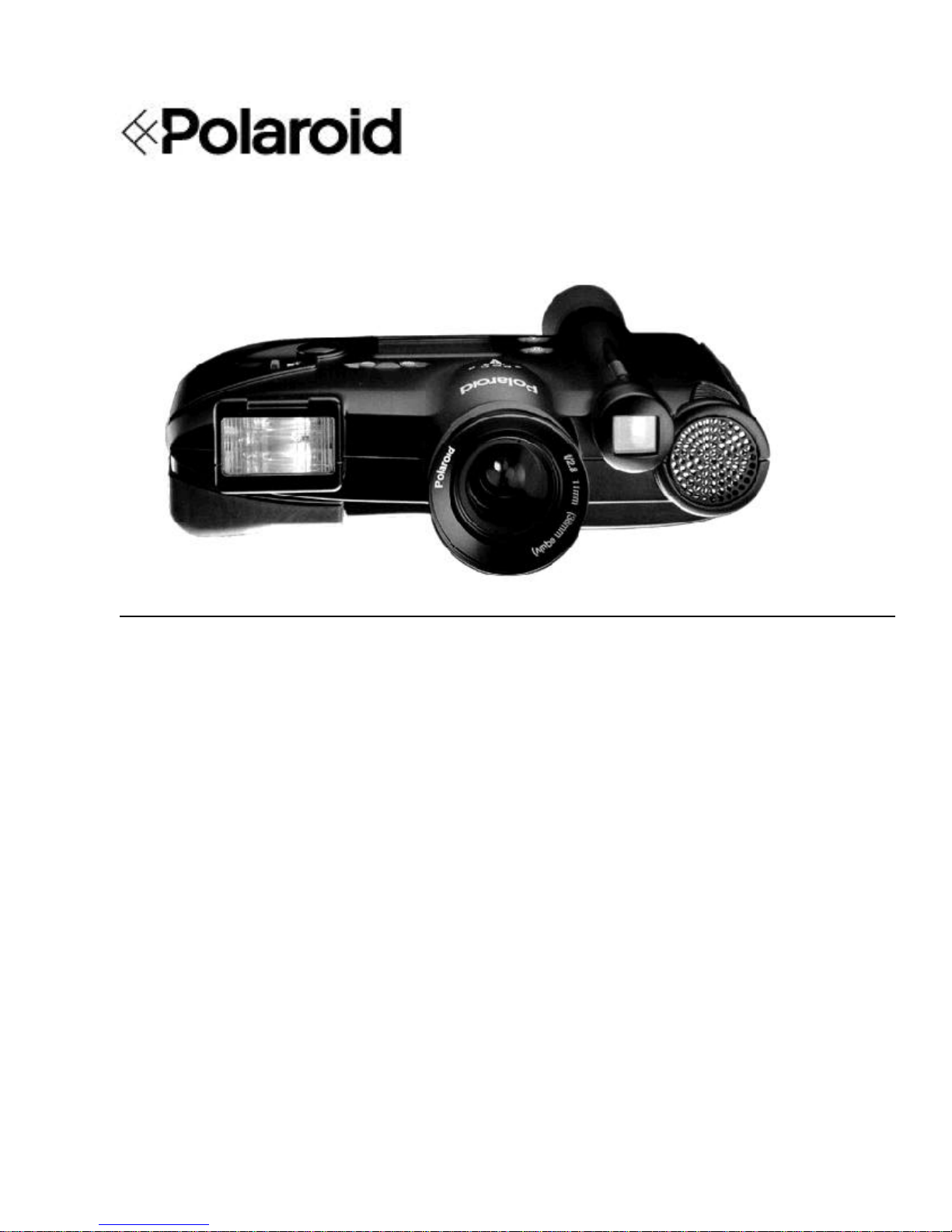
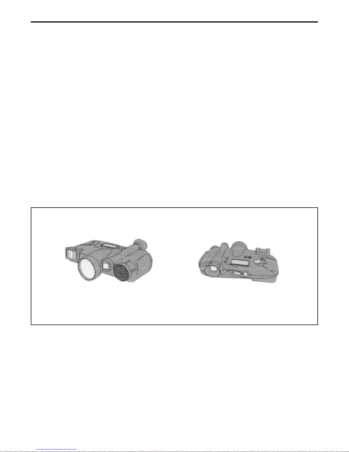
The Polaroid Digital Camera, Model PDC-2000 (Figure 1-1), captures high-quality color
pictures electronically. It has all the features of an automatic compact 35mm camera, including
automatic exposure, electronic flash and automatic focus. These features produce correct
exposure, accurate colors and sharp focus under a great variety of picture-taking conditions.
Manual overrides are also provided for unusual conditions.
With appropriate image-processing software (such as Polaroid PicturePro or Adobe
Photoshop) and the Polaroid PDC-2000 plug-in software on a Macintosh computer or PC,
users can view the pictures taken with the PDC-2000 camera and transfer them to their
computer via a standard SCSI-2 interface. They can then use image-processing software to
manipulate, enhance, save and print the pictures.
When the camera is connected to a computer, the camera can be controlled and operated via
the computer keyboard and mouse. This is useful when the camera is used in a stationary
setup.
Front
Rear
Figure 1-1. Polaroid digital camera, model PDC-2000
Models
The PDC-2000 is available in three different models:
Model Internal Storage Capacity (Megabytes)
PDC-2000/40 40 (40 images)
PDC-2000/60 60 (60 images)
PDC-2000/T None; tethered operation only
6

PDC 2000/3000 Repair Manual Description
Tethered operation refers to operation of the camera while it is connected to a computer. The
PDC-2000/T has no internal storage and must be connected to a computer to be operable.
Instead of storing images internally, it immediately transfers them to the computer as they are
captured.
Features
The PDC-2000 is designed for completely automatic, point-and-shoot operation. It
automatically sets exposure, focus and flash mode based on ambient light and distance to the
subject. Manual overrides are available for setting focus to infinity, setting flash mode to on or
off, and setting white balance to daylight, incandescent or fluorescent. A backlightcompensation setting is also available.
The camera is capable of transferring its images to the computer in either of two resolutions:
(1) standard (800x600 dpi) and high (1600x1200 dpi). Both resolution modes are 24-bit color.
Because the camera always stores enough raw image data to produce the high resolution
images, resolution is not selected until pictures are being transferred to the computer.
Power for the camera is provided by four AA rechargeable NiCad batteries. These batteries
can be charged in the camera, using the battery charger provided with the camera. The
camera is operable while the batteries are charging.
An LCD panel on the camera provides information about time and date, camera status,
remaining battery capacity and error conditions. Time and date are recorded in the header of
each picture file, and on-camera controls allow the user to attach an additional alphanumeric
label to each picture file header. Time, date, label, and camera status transfer with the image
to the computer to aid identification and troubleshooting.
Specifications
Description: Captures high-quality digital photographs, previously
available only from professional SLR digital cameras, with
point-and-shoot ease of use
PDC-2000 models: PDC-2000/40 - 40 megabytes of internal storage
PDC-2000/60 - 60 megabytes of internal storage
PDC-2000/T - No internal storage; tethered operation only
Automatic adjustments • Focus
in standard mode: • Exposure
• Flash on or off
7

PDC 2000/3000 Repair Manual Description
Manual controls User-selected manual controls for:
and overrides:
• Backlight conditions
• White balance options: daylight, incandescent or fluorescent
• Flash options: automatic, on or off
• Auto focus or fixed focus
• 10 character alpha-numeric image label
Sensor: Polaroid 1 million pixel CCD sensor
Resolution: Standard: 800 x 600 dpi, 24-bit color, 16.7 million colors,
1.4 MB file
High: 1600 x 1200 dpi, 24-bit color, 16.7 million colors, 5.6MB file
Image storage PDC-2000/40 - 40 images
capacity: PDC-2000/60 - 60 images
PDC-2000/T - No internal storage for images
Computer interface: SCSI-2
Standard lens: f/2.8, 11mm (38mm equivalent)
Focus range: 10 inches to infinity
Equivalent film speed: ISO 100
Shutter: Scanning aperture shutter (microprocessor controlled)
Shutter speed: 1/25 to 1/500 seconds
Aperture: f/2.8 - f/11
Flash: Internal, up 15 feet
Power supply: • 4 rechargeable AA NiCad batteries
• IEC Universal Power Adapter
Battery life: More than 150 pictures (at 50% flash use)
Dimensions: Length - 20.1cm (7.9 inches)
Width - 16.0 cm (6.3 inches)
Height - 5.6 cm (2.2 inches)
Weight (with batteries): 0.9 kg (2.0 lbs.)
8

PDC 2000/3000 Repair Manual Description
Standard accessories: • SCSI connector cable
• 25/50 SCSI adapter
• 4 rechargeable AA NiCad batteries
• IEC universal power adapter
• Country version power cord
• Neck strap
Software provided: • Plug-in for PhotoShop (Mac/Windows)
• Polaroid PicturePro (Mac/Windows)
• T WAIN driver for Windows
Optional accessories: • f/3.5, 17mm Lens (60mm equivalent); focus range: 24 inches
to infinity
• Slim SCSI card (PCMCIA-to-SCSI adapter for portable PCs
using the PCMCIA slot)
• 4-pack rechargeable AA NiCad batteries
• Eveready 5 hour charger
• 12 volt auto adapter
• Polaroid camera bag
Macintosh operating • Apple Macintosh or Powerbook computer with a 68030 or
requirements: later processor.
• Macintosh system software version 7.1 or later.
• 8 megabytes of available RAM (16 MB recommended).
• 10 megabytes of available hard disk space.
IBM/compatible • IBM PC or compatible computer with a 386 or later
operating processor (486 recommended)
requirements: • ASPI-compliant SCSI adapter card
• Microsoft Windows 3.1 or later
• 8 megabytes of available RAM (16 MB recommended)
• 10 megabytes of available hard disk space
9
PDC 2000/3000 Repair Manual Theory of Operation
2. Theory of Operation
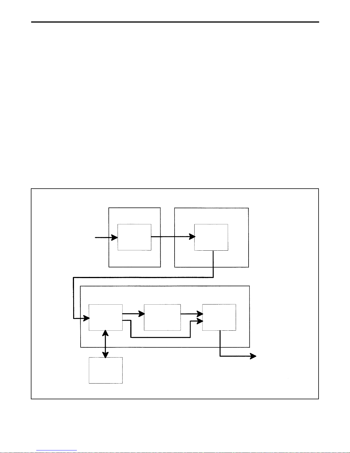
Picture Data Flow
Picture data flows through the PDC-2000 camera from the CCD sensor to the SCSI interface is
shown in Figure 2-1. This analog and digital data is processed through the following modules:
• CCD sensor
• Video signal processor
• Frame buffer
• Internal storage
• Median filter interpolator
• SCSI interface
Light from Scene
Optics Module Front End (Analog) Board
CCD
Back End (Digital) Board
Frame
Buffer
Median
Filter
Interpolator
Video
Signal
Processor
SCSI
Interface
Internal
Storage
Figure 2-1. Picture data flow through PDC-2000
Picture Data
to Host via
SCSI Connector
10

PDC 2000/3000 Repair Manual Theory of Operation
Median Filter Interpolator
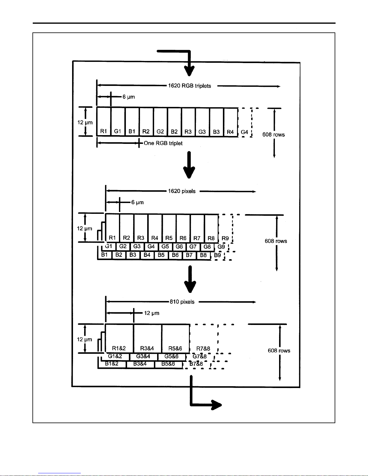
Standard Resolution Mode
The median filter interpolator converts RGB triplets received from the frame buffer to an 800 x 600
(standard resolution for the PDC-2000) RGB image by arranging the pixels and averaging
adjacent horizontal pixels as shown in Figure 2-2. It sends the reconstructed pixel data to the
SCSI interface.
11
PDC 2000/3000 Repair Manual Theory of Operation
From Frame Buffer
Median Filter Interpolator
Figure 2-2. Median filter interpolator function
To SCSI Interface
and Host Computer
12

PDC 2000/3000 Repair Manual Theory of Operation
High Resolution Mode
When the operator through the host computer decides to transfer a picture in the high-resolution
mode (1600 x 1200) instead of standard resolution, data from the frame buffer passes directly to
the SCSI interface without passing through the camera’s median filter interpolator (Figure 2-1).
In this high resolution mode, the host computer processes the frame buffer data to produce a
1600 x 1200 pixel image as shown in Figure 2-3.
13

PDC 2000/3000 Repair Manual Theory of Operation
From Camera Frame Buffer
(Via SCSI Interface)
High-Resolution Proccessing
(Host Computer)
Figure 2-3. High resolution mode processing within host
T o Image-Processing
Application on Host Computer
14

PDC 2000/3000 Repair Manual Testing&Adjustment
3. PDC-2000 Testing and Adjustment
LabView
Overview
LabView is a graphical application program designed by National Instrument. It is used to
graphically program instrumentation systems for data acquisition and control, data analysis,
and data presentation. This application program offers an innovative method in which a
design engineer can graphically assemble software modules called virtual instruments (VI's)
instead of writing text-based programs. VI's can be used to acquire data from plug-in boards
and programmable instruments such as PDC 2000/3000 digital cameras. VI's can also be
assembled to analyze data and to present results through graphical user interfaces.
A LabView virtual instrument (VI) consists of:
• Front Panel
• Block Diagram
• Icon/Connector
The following paragraphs only gives an overview of the LabView components necessary to
design a test program. Refer to the LabView User's Guide for more detailed information
pertaining to the LabView components necessary to design a test program.
Front Panel
The front panel is the user interface. It serves as an interactive interface for supplying
inputs to and observing outputs from the instrumentation system. LabView makes
creating a front panel as simple as drawing a picture and gives the user a variety of
controls and indicators to use.
When the VI is completed, the user uses it to control his/her system - even while the VI is
running - by clicking a switch, moving a slide, tweaking a knob, or entering a value from
thekeyboard, the front panel responds immediately, providing real-time feedback from the
instrumentation system.
Once the necessary information is entered or selected from the applicable front panel, the
user then starts the VI by clicking on the Start button. It then performs the test and
displays its results in the Test Status window on the front panel. Refer to the applicable
Testing and Adjustment section for a detailed explanation of the PDC 2000/3000 front
panel.
15

PDC 2000/3000 Repair Manual Testing&Adjustment
Block Diagram
The block diagram is the source code of the VI. It is constructed, free from syntactical
details of conventional programming, by selecting functional blocks from LabView menus.
The selected functional blocks are then connected with lines called wires to pass data from
one block to the next. These blocks include arithmetic functions, advanced acquisition and
analysis VI's, Sub VI components which call other VI's, and network and file I/O functions
that store or retrieve data in ASCII, binary, or spreadsheet formats.
Icon/Connector
The icon/connector is the calling interface. The icon is the graphical ID of the VI, and the
connector assigns controls and indicators to VI input and output terminals.
Test Software
The Test Software is an application program that was developed using LabView software
(National Instrument) and Concept VI Image Processing Library (Graftek). It is intended to
help the repair person diagnose PDC 2000/3000 digital camera malfunctions. Programs
developed using LabView are called virtual instruments (VI's).
The developed software consists of a Tester which invokes the necessary sub-VI's routines
that allow the repair person to check the PDC 2000/3000 digital camera.
When the Tester is invoked, it performs and verifies specified camera tests.
At the completion of the specified test, a report file is generated by the Tester indicating
whether or not the tested functions passed ( Pass ) or failed ( Fail ). It also list the current
parameters for the test functions so that repair person can verify the tested functions with the
PDC 2000/3000 digital camera specifications.
If the report file indicates that all or a particular function failed ( Fail ), the repair person can
compare the current parameters with the PDC 2000/3000 digital camera specifications to
determine how to bring the failed function/functions back into specification.
16

PDC 2000/3000 Repair Manual Testing&Adjustment
Tester Operation
Starting the Tester
1. If applicable, click the mouse on the front panel white arrow to start the tester.
2. Click the mouse on the Start button to start the test sequence.
3. Tester prompts the user to perform specified function when testing the PDC 2000/3000
digital camera.
4. Once all user prompts are completed, the test sequence for the PDC 2000/3000 digital
camera begins.
5. Upon completion of all or partial tests, a test completed message appears in the Status box
of the test panel.
Also, a test report and the Pass / Fail indicators displayed on the test panel are updated.
Stopping the Tester
Note: The Tester should not be stopped in the middle of a test sequence. However, if an
emergency situation occurs, use the following steps to stop and restart the Tester.
1. Click the mouse on the stop box to completely stop the camera's test sequence.
The black arrow changes to a white arrow indicating that the run-time version of LabView
stopped running.
2. To restart the Tester, just click the mouse on the white arrow; the arrow becomes black
again and the tester resumes.
Quitting the Tester
To quit the Tester due to a malfunction or before the selected tests are completed, just
click the mouse on the Closing box.
17

PDC 2000/3000Repair Manual Testing&Adjustment
Testing and Adjustment Guidelines
As the selected LabView test program runs, many windows and dialog boxes appear and
disappear throughout the test process. Use the following test guidelines to perform the
requested user tasks.
• Yes/No - Click on appropriate response (Yes or No).
Dialog Boxes
• Message Windows - Perform requested task and then click on Start button.
w/Start Button
• Auto Sequence - No user input.
Windows
18

PDC 2000/3000 Repair Manual Testing&Adjustment
Testing and Adjustments
Current Profile Test
Required Test Equipment and Tools
• Macintosh Centris 650 Computer or Equivalent
• 1-ohm resistor box
• 0 - 10 Vdc Power Supply
• Camera Test Fixture (Nest)
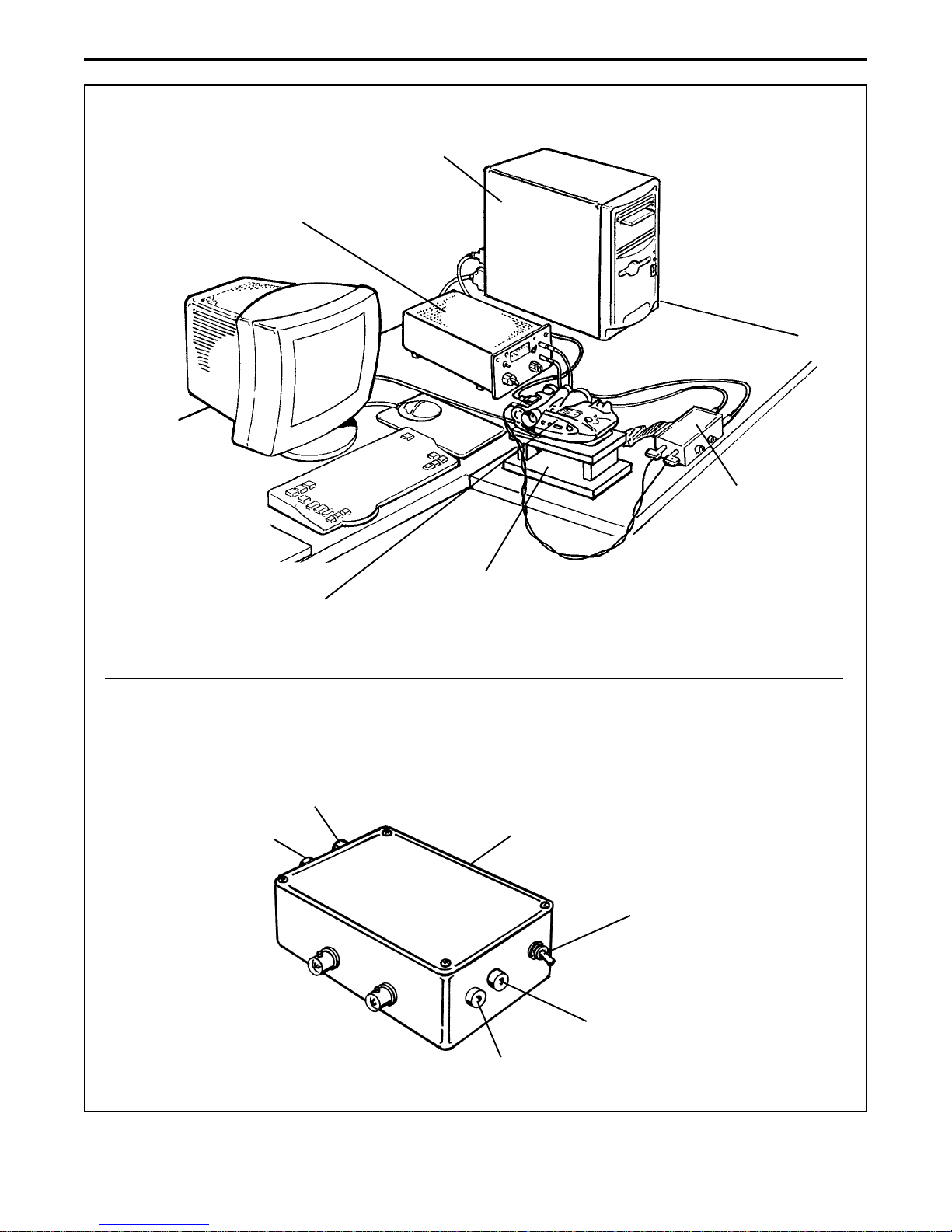
Equipment Setup (Figure 3-1)
1. Place the camera onto a workbench.
2. Connect the external power supply output cable to the 6 Vdc input on the 1-ohm resistor
box.
3. Connect the 1-ohm resistor box 6 Vdc output cable to the camera power jack.
4. Connect the computer ribbon cable to the 1-ohm resistor box.
5. Turn on the test equipment as follows:
• Macintosh Centris 650 computer On/Off (0/1) switch to On (1).
• 0 - 10 Vdc external power supply On/Off switch to On. Adjust power supply output to
6 Vdc.
19
PDC 2000/3000 Repair Manual Testing&Adjustment
Equipment
Setup
Macintosh Centris 650
Power PC
External Power
Supply (6 Vdc)
1-Ohm
Resistor Box
1-Ohm
Resistor Box
PDC2000/3000
Camera
6 Vdc - Out to PC
Grn
T est Fixture
(Nest)
Ribbon Cable - not shown
(Out to computer)
Manual/L V
(LabView)
Switch
6Vdc - In
(From external power supply)
Grn
Figure 3-1. Current profile equipment setup
20
PDC 2000/3000 Repair Manual Testing&Adjustment
Test Procedure
1. If applicable, enter user password.
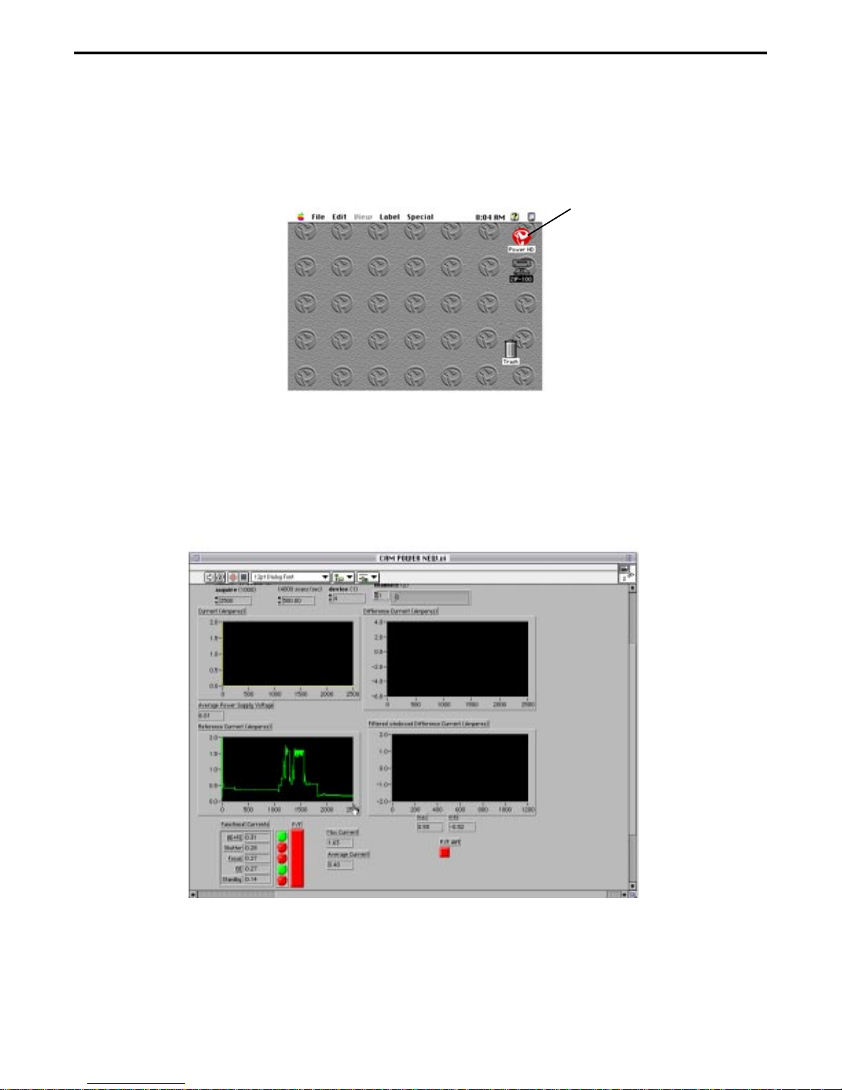
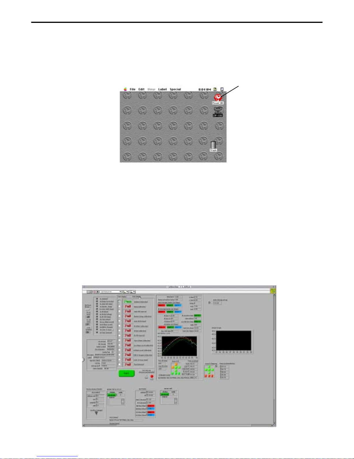
2. Double click on the hard drive (HD) icon. The HD windows appears.
HD Icon
3. Double click on the Current Profile VI icon.
This action loads the specified LabView VI test program.
4. Once the LabView VI test program is loaded, the Cam Power New.VI panel appears.
5. Set the 1-ohm resistor box Manual/LV switch to Manual.
6. Turn on the digital camera under test.
Note: Make sure camera strobe is turned off.
21
PDC 2000/3000 Repair Manual Testing&Adjustment
7. Set the 1-ohm resistor box Manual/LV switch to LV (LabView).
8. Click on the white arrow. Arrow should change to black.
9. Click on the black arrow to start the selected LabView VI test program.
The test program starts as indicated by the yellow Running box directly under the black
start arrow.
Note: Follow all instructions that appear on the screen while the test program runs.
Click on the appropriate responses that appear in the dialog boxes.
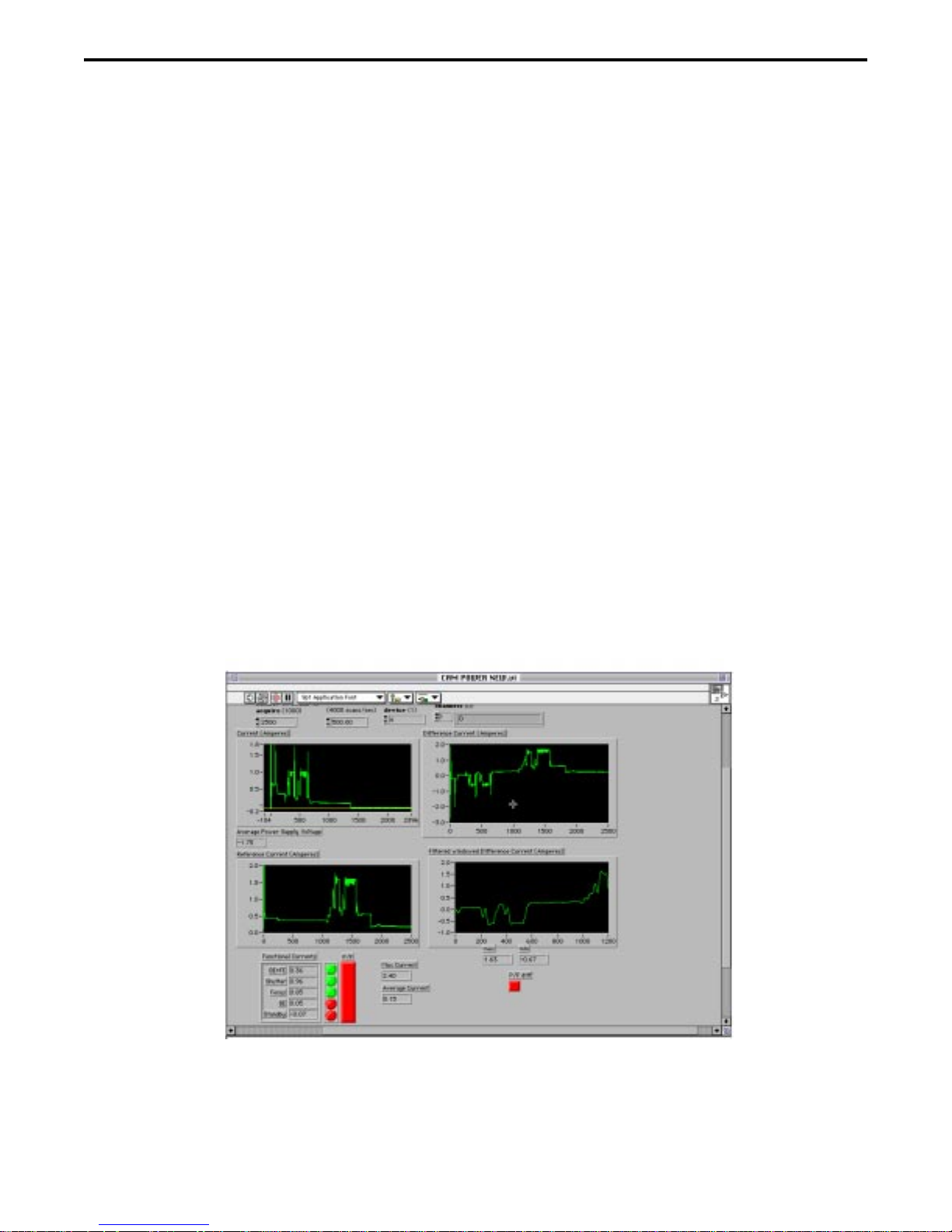
10.Upon completion of the current profile test program, current waveforms for the following
appear:
• Current (Amperes) - Waveform should be smooth.
• Reference Current (Amperes) - Waveform should be smooth.
• Difference Current (Amperes) - Not used.
• Filtered Windowed Difference current (Amperes) - Not used.
Note: Spikes displayed in the current profile waveforms indicate that the camera is
defective. Refer to the camera troubleshooting section in the repair manual to
determine the cause of the camera malfunction and how to correct it.
22

PDC 2000/3000 Repair Manual Testing&Adjustment
Calibration
Required Test Equipment and Tools
• Power Computing Power PC or equivalent
• PDC2000 Switching Power Supply
• Camera SCSI Cable
• Camera Test Fixture (Nest)
• Keithly 485 AutoRanging Picoammeter or Equivalent
• Polaroid Model B Light Source (PDC Blue Box) with Photodiode
attached to glass
• Graywall Booth
• Diorama Test Bench
• PDC Diorama Camera Test Fixture (Nest)
• MacBeth Color Chart
• Neutral Density Filter
• Auxiliary Strobe
23

PDC 2000/3000 Repair Manual Testing&Adjustment
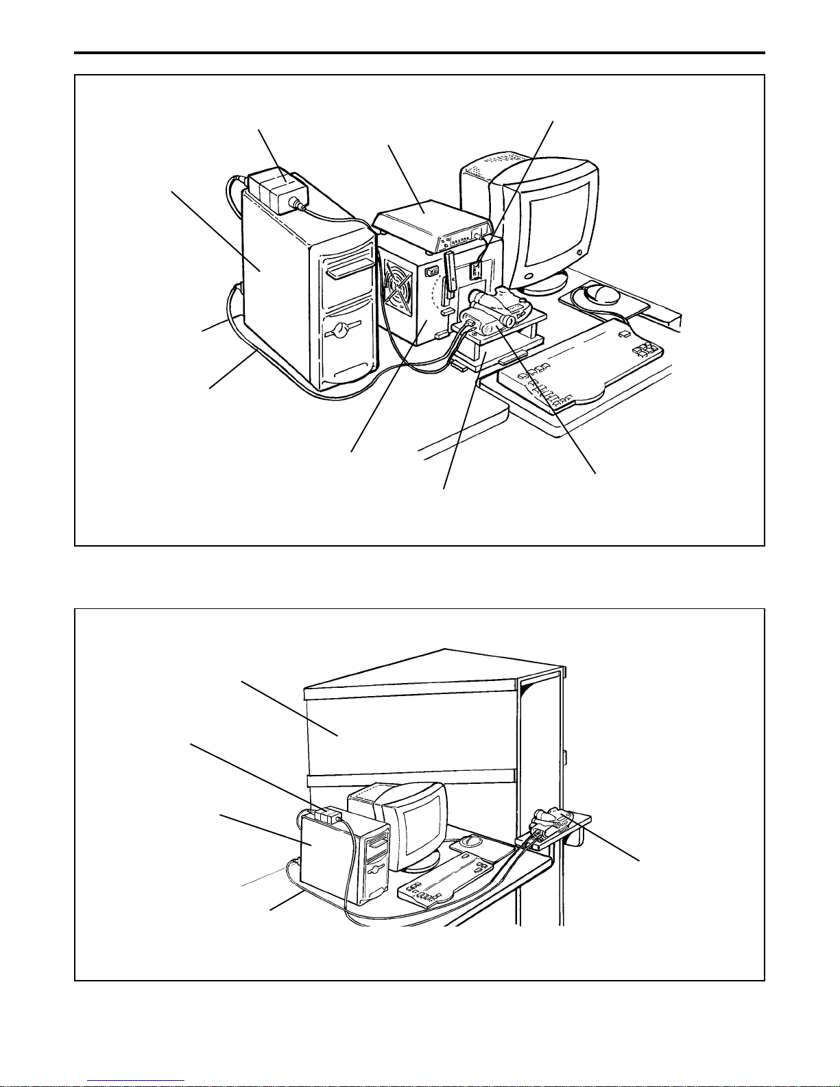
Equipment Setup (Figures 3-2 through 3-6)
Note: Figures 3-2 through 3-6 shows the equipment setup for the ambient, strobe and
color/focus parts of the calibration procedure.
1. Place the camera onto the test fixture (camera nest).
2. Connect the camera SCSI cable from the host computer SCSI connector to the camera
SCSI connector.
3. Connect the switching power supply cable to the camera’s external power connector.
4. If applicable, set the camera’s SCSI ID to 4.
5. If applicable, replace camera lens with an 11mm lens.
Note: 11mm lens is standard. Some camera’s come in for repair with the
optional 17mm lens attached.
For testing purposes the standard 11mm lens must be used.
6. Turn on the test equipment as follows:
• Power Computing PC On/Off (0/1) switch to On (1).
• Keithly 485 AutoRanging Picoammeter On/Off pushbutton to On. Adjust to ????.
• Model B Light Source Power On/Off rocker switch to On.
Note: Allow the Model B Light Source to warm up for approximately
five (5) minutes before use.
• Turn on the camera.
24
PDC 2000/3000 Repair Manual Testing&Adjustment
Camera Power
Power Computing
Power PC
Camera
SCSI Cable
Supply
Picoammeter
Model B
Light Box
Camera Nest
Photodiode
PDC 2000/3000
Camera
Graywall
Booth
Camera Power
Supply
Power Computing
Power PC
SCSI Cable
Figure 3-2. Ambient setup
PDC 2000/3000
Camera
Camera
Figure 3-3. Strobe setup
25

PDC 2000/3000 Repair Manual Testing&Adjustment
Diorama
Bench
Camera Power
Supply
Power Computing
Power PC
Camera
SCSI Cable
Macbeth Color
Checker Chart
Resolution
Neutral Density
Filter
Auxiliary
Strobe
Chart
PDC 2000/3000
Camera
Diorama
Camera Nest
Figure 3-4. Color and focus test (macbeth color checker chart)
Camera Power
Supply
Power Computing
Power PC
Camera
SCSI Cable
Diorama
Bench
Neutral Density
Checker/Resolution
T arget
Filter
Auxiliary
Strobe
PDC 2000/3000
Camera
Diorama
Camera Nest
Figure 3-5. Color and focus test (checker/resolution target in front of camera)
26

PDC 2000/3000 Repair Manual Testing&Adjustment
Camera Power
Supply
Power Computing
Power PC
Camera
SCSI Cable
Diorama
Bench
PDC 2000/3000
Camera
Neutral Density
Filter
Camera Nest
Auxiliary
Strobe
Diorama
Figure 3-6. Color and focus test (vertical)
27
PDC 2000/3000 Repair Manual Testing&Adjustment
Test Procedure
1. If applicable, enter user password.
2. Double click on the hard drive (HD) icon. The HD windows appears.
HD Icon
3. Double click on the PDC Calibration folder. The PDC Calibration window appears.
4. Double click on the applicable Calibration icon. The Calibration window appears.
Notes: • 40/60 hard drive camera type - click on V3.020 icon
• Tither camera type - click on V3.021 icon
5. Double click on the Calibration .iib icon. This action loads the specified LabView VI test
program.
6. Once the LabView VI test program is loaded, the Calibration front panel appears.
28
PDC 2000/3000 Repair Manual Testing&Adjustment
7. Set test parameters as follows: (Left side of VI front panel)
• Do no tests to OFF
• Do all tests to ON
• Load defaults to ON
8. Click on the white arrow. Arrow should change to black.
9. Click on the green Start button to automatically start the selected LabView VI test
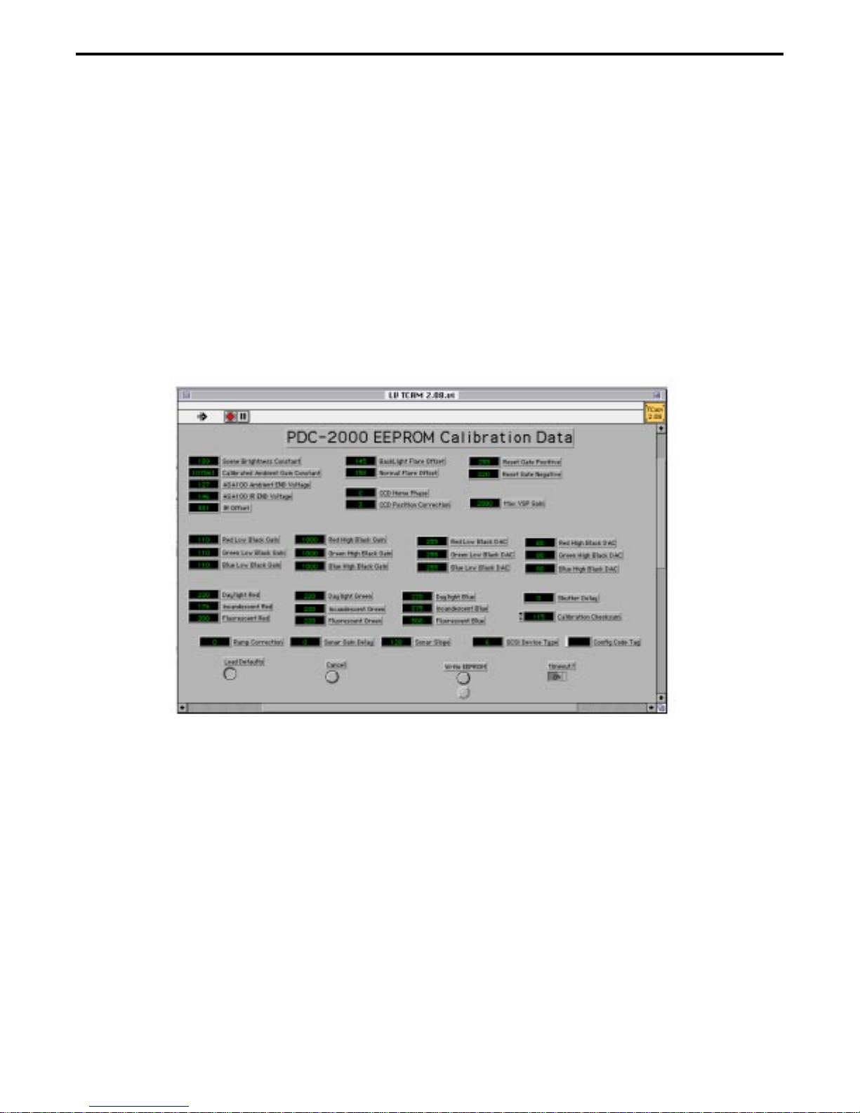
program. The EEPROM calibration data panel appears.
Note: If the camera is not turned on, turn on the camera under test and then
repeat step 7 through 9.
10. Click on the Start button to automatically start the ambient part of this calibration
procedure.
Note: Follow all instructions that appear on the screen while the ambient part of this
calibration procedure runs. Click on the appropriate responses that appear in
the dialog boxes.
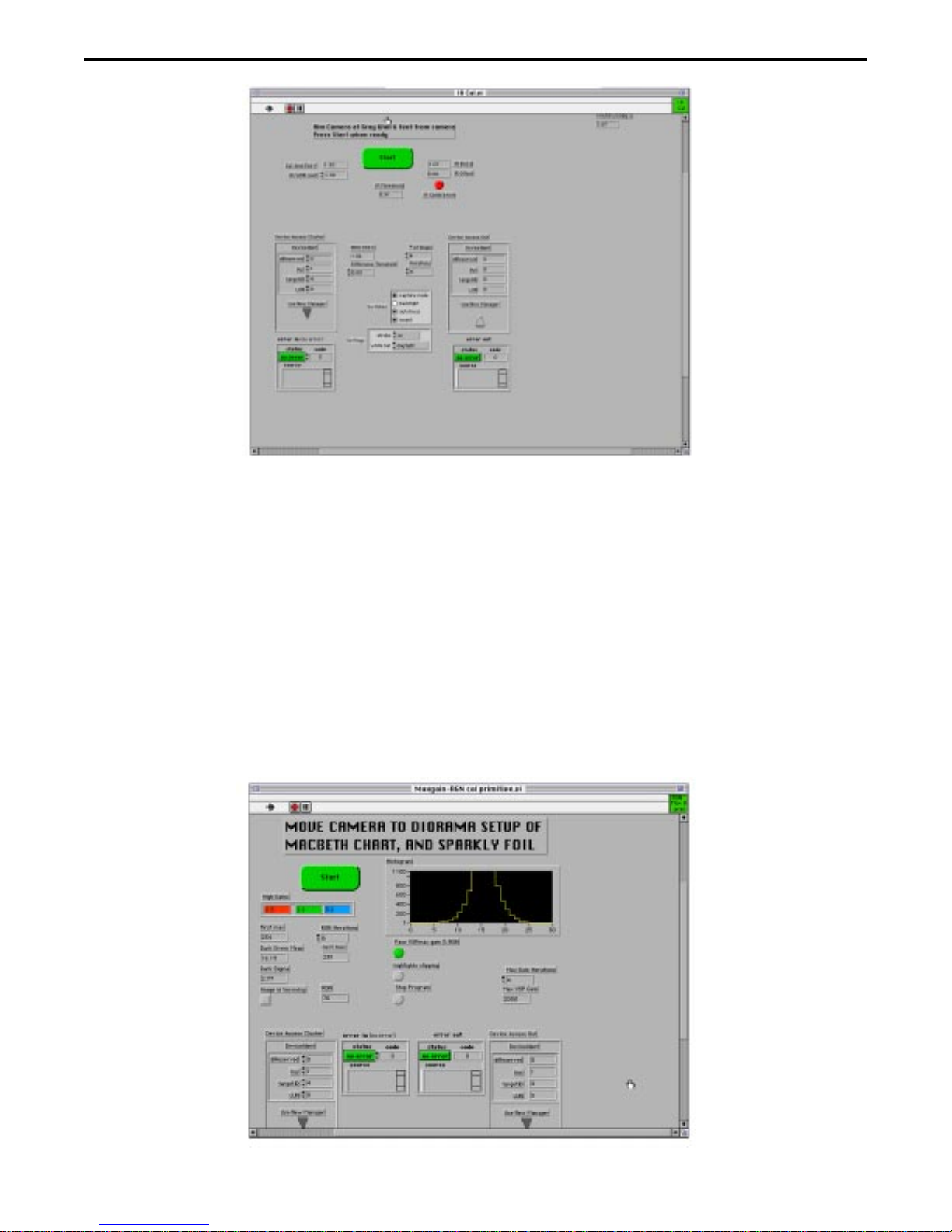
11. Upon completion of the ambient part of the calibration procedure, the IR CAL.VI panel
appears. This panel prompts you to move the camera under test to the Graywall Booth
(Figure 3-3).
29
PDC 2000/3000 Repair Manual Testing&Adjustment
12. Place the camera and nest onto the shelf in front of the Greywall Booth (Figure 3-3).
13. Click on the Start button to automatically start the strobe part of this calibration
procedure.
Note: Follow all instructions that appear on the screen while the strobe part of this
calibration procedure runs. Click on the appropriate responses that appear in
the dialog boxes.
14. Upon completion of the strobe part of the calibration procedure, a prompt appears
indicating that the camera be moved to the Diorama bench (Figure 3-4).
30
 Loading...