

Page 1

Industrial 5-Port 10/100/1000T VPN Security Gateway
IVR-100
Industrial 5-Port 10/100/1000T VPN
Security Gateway
IVR-100
- 1 -
Page 2

Industrial 5-Port 10/100/1000T VPN Security Gateway
IVR-100
Copyright
Copyright (C) 2020 PLANET Technology Corp. All rights reserved.
The products and programs described in this User’s Manual are licensed products of PLANET
Technology, This User’s Manual contains proprietary information protected by copyright, and this
User’s Manual and all accompanying hardware, software, and documentation are copyrighted.
No part of this User’s Manual may be copied, photocopied, reproduced, translated, or reduced to any
electronic medium or machine-readable form by any means, electronic or mechanical including
photocopying, recording, or information storage and retrieval systems, for any purpose other than the
purchaser's personal use, and without the prior express written permission of PLANET Technology.
Disclaimer
PLANET Technology does not warrant that the hardware will work properly in all environments and
applications, and makes no warranty and representation, either implied or expressed, with respect to
the quality, performance, merchantability, or fitness for a particular purpose.
PLANET has made every effort to ensure that this User’s Manual is accurate; PLANET disclaims
liability for any inaccuracies or omissions that may have occurred. Information in this User’s Manual is
subject to change without notice and does not represent a commitment on the part of PLANET.
PLANET assumes no responsibility for any inaccuracies that may be contained in this User’s Manual.
PLANET makes no commitment to update or keep current the information in this User’s Manual, and
reserves the right to make improvements and/or changes to this User’s Manual at any time without
notice.
If you find information in this manual that is incorrect, misleading, or incomplete, we would appreciate
your comments and suggestions.
FCC Compliance Statement
This Equipment has been tested and found to comply with the limits for a Class A digital device,
pursuant to Part 15 of the FCC rules. These limits are designed to provide reasonable protection
against harmful interference in a residential installation. This equipment can radiate radio frequency
energy and, if not installed and used in accordance with the instructions, may cause harmful
interference to radio communications.
However, there is no guarantee that interference will not occur in a particular installation. If this
equipment does cause harmful interference to radio or television reception, which can be determined
by turning the equipment off and on, the user is encouraged to try to correct the interference by one or
more of the following measures:
– Reorient or relocate the receiving antenna.
- 2 -
Page 3

Industrial 5-Port 10/100/1000T VPN Security Gateway
IVR-100
– Increase the separation between the equipment and receiver.
– Connect the equipment into an outlet on a circuit different from that to which the receiver is
connected.
– Consult the dealer or an experienced radio/TV technician for help.
CE mark Warning
The is a class A device, In a domestic environment, this product may cause radio
interference, in which case the user may be required to take adequate measures.
WEEE
To avoid the potential effects on the environment and human health as a result of the
presence of hazardous substances in electrical and electronic equipment, end users of
electrical and electronic equipment should understand the meaning of the crossed-out
wheeled bin symbol. Do not dispose of WEEE as unsorted municipal waste and have to collect such
WEEE separately.
Trademarks
The PLANET logo is a trademark of PLANET Technology. This documentation may refer to numerous
hardware and software products by their trade names. In most, if not all cases, these designations are
claimed as trademarks or registered trademarks by their respective companies.
Revision
User’s Manual of PLANET Industrial 5-Port 10/100/1000T VPN Security Gateway
Model: IVR-100
Rev.: 1.0 (December, 2020)
Part No. EM-IVR-100_v1.0
- 3 -
Page 4

Industrial 5-Port 10/100/1000T VPN Security Gateway
Table of Contents
Chapter 1. Product Introduction ............................................................................................. 6
1.1 Package Contents ...................................................................................................... 6
1.2 Overview .................................................................................................................... 6
1.3 Topology ................................................................................................................... 11
1.4 Features ................................................................................................................... 12
1.5 Product Specif ic ations ............................................................................................. 14
Chapter 2. Hardware Introduction ....................................................................................... 17
2.1 Physical Desc ript ions ............................................................................................... 17
2.1.1 Front View .............................................................................................. 17
2.1.2 Top View ................................................................................................ 18
2.1.3 Wiring the Power Inputs ......................................................................... 18
IVR-100
2.1.4 Wiring the Fault Alarm Contact .............................................................. 19
2.1.5 Dimensions ............................................................................................ 21
2.2 Hardware Installation ............................................................................................... 22
2.2.1 DIN-rail Mounting ................................................................................... 22
2.2.2 Wall Mount Plate Mounting .................................................................... 23
2.2.4 Side Wall Mount Plate Mounting ............................................................ 25
Chapter 3. Preparation ........................................................................................................ 26
3.1 Requirements ........................................................................................................... 26
3.2 Setting TCP/IP on your PC ...................................................................................... 26
3.2.1 Windows 7/8 .......................................................................................... 26
3.2.2 Windows 10 ........................................................................................... 30
3.3 Planet Smart Discovery Utility .................................................................................. 33
Chapter 4. Web-based Management .................................................................................. 35
4.1 Introduction .............................................................................................................. 35
4.2 Logging in to the VPN Gateway ............................................................................... 35
4.3 Main Web Page ........................................................................................................ 36
4.4 System ..................................................................................................................... 38
4.4.1 Setup Wizard ......................................................................................... 39
4.4.2 Dashboard ............................................................................................. 45
4.4.3 Status ..................................................................................................... 46
4.4.4 Statistics ................................................................................................. 47
4.4.5 Connection Status ................................................................................. 47
4.4.6 SNMP ..................................................................................................... 48
- 4 -
Page 5

Industrial 5-Port 10/100/1000T VPN Security Gateway
4.5 Network .................................................................................................................... 49
4.5.1 WAN ....................................................................................................... 50
4.5.2 WAN Advanced ...................................................................................... 51
4.5.3 LAN Setup.............................................................................................. 52
4.5.4 Routing ................................................................................................... 53
4.5.5 WAN IPv6 Setting .................................................................................. 54
4.5.6 DHCP ..................................................................................................... 55
4.5.7 DDNS ..................................................................................................... 57
4.5.8 MAC Address Clone .............................................................................. 59
4.6 Security .................................................................................................................... 60
4.6.1 Firewall ................................................................................................... 61
4.6.2 MAC Filtering ......................................................................................... 63
4.6.3 IP Filtering .............................................................................................. 64
4.6.4 Web Filtering .......................................................................................... 65
4.6.5 Port Forwarding ..................................................................................... 66
IVR-100
4.6.6 DMZ ....................................................................................................... 67
4.7 VPN 68
4.7.1 IPSec ..................................................................................................... 69
4.7.2 GRE ....................................................................................................... 74
4.7.3 PPTP Server .......................................................................................... 76
4.7.4 L2TP Server ........................................................................................... 80
4.7.5 SSL VPN ................................................................................................ 85
4.7.6 VPN Connection .................................................................................... 86
4.8 Maintenance ............................................................................................................. 87
4.8.1 Administrator .......................................................................................... 87
4.8.2 Date and Time ....................................................................................... 88
4.8.3 Saving/Restoring Configuration ............................................................. 89
4.8.4 Upgrading Firmware .............................................................................. 90
4.8.5 Reboot / Reset ....................................................................................... 90
4.8.6 Diagnostics ............................................................................................ 91
Appendix A: DDNS Application .............................................................................................. 93
- 5 -
Page 6
Industrial 5-Port 10/100/1000T VPN Security Gateway
Chapter 1. Product Introduction
1.1 Package Conte nts
The package should contain the following:
VPN Gateway x 1
Quick Installation Guide x 1
Wall-mount Kit x 1
Dust Cap x 5
If any of the above items are missing, please contact your dealer immediately.
IVR-100
1.2 Overview
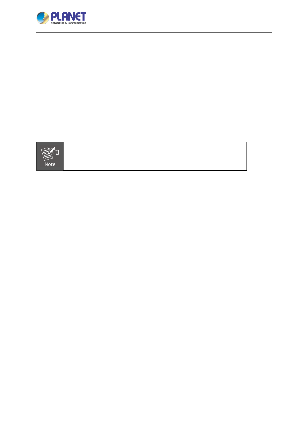
Powerful Industrial VPN Security Solution
The innovation of the Internet has created tremendous worldwide opportunities for e-business and
information sharing. It has become essential for businesses to focus more on network security issues.
The demand for information security has become the primary concern for the enterprises. To fulfill this
demand, PLANET has launched the IVR-100 Industrial VPN Security Gateway, an all-in-one appliance
that carries several main categories across your industrial network security deployments: Cyber
security, SPI firewall security protection, policy auditing (Content Filtering, VPN Tunnel an d V LA N ) , and
easy management (Setup Wizard, QoS and Dashboard). Furthermore, its Dual-WAN Failover and
Outbound Load Balancing features can improve the network efficiency while the web-based interface
provides friendly and consistent user experience. For the harsh environment, the IVR-100 can not onl y
operate stably under temperature range from -40 to 75 degrees C, but also is equipped with a compact
IP30 metal case that allows either DIN-rail or wall mounting for efficient use of cabinet space.
- 6 -
Page 7
Industrial 5-Port 10/100/1000T VPN Security Gateway
IVR-100
Excellent Ability in Threat Defense
The IVR-100 built-in SPI (stateful packet inspection) firewall and anti DoS/DDoS attack functions
provide high efficiency and extensive protection for your network. Virtual server and DMZ functions can
let you set up servers in the Intranet and still provide services to the Internet users.
Ideal VPN Security Gateway Solution for SMBs
The IVR-100 provides complete data security and privacy for accessing and exchanging most sensitive
data, built-in IPSec VPN function with DES/3DES/AES encryption and
MD5/SHA-1/SHA-256/SHA-384/SHA-512 authentication, and GRE, SSL, PPTP and L2TP server
mechanism. The full VPN capability in the IVR-100 makes the connection solidly secure, more flexible,
and more capable.
The IVR-100 supports many popular security features including Content Filtering to block specific URL,
MAC/IP filtering, outbound load balancing and more. Furthermore, it provides higher performance with
all Gigabit Ethernet interfaces which offer faster speeds for your network applications. The Gigabit
- 7 -
Page 8
Industrial 5-Port 10/100/1000T VPN Security Gateway
IVR-100
user-defined interfaces flexibly fulfill the network requirements, and the dual-WAN interfaces enable the
IVR-100 to support outbound load balancing and WAN fail-over features.
Cybersecurity Network Solution to Minimize Security Risks
The cybersecurity feature included to protect the switch management in a mission-critical network
virtually needs no effort and cost to install. For efficient management, the IVR-100 is equipped with
HTTPS web and SNMP management interfaces. With the built-i n web-based management interface,
the IVR-100 offers an easy-to-use, platform independent management and configuration facility. As the
IVR-100 supports SNMP, it can be managed via any management software based on the standard
SNMP protocol.
Improving Network Efficiency
The IVR-100 has link redundancy, content filtering and many more functions to make the entire network
system perform better. It is applicable to the small-scale sector (from 10 to 50 people), using a compact
industrial design, with five Gigabit ports (WAN/LAN). The IVR-100’s economical price with complete
cable management features make it an inevitable choice for the next-generation office network load
balancer.
The IVR-100’s built-in content filtering feature can automatically resolve the IP address corresponding
to all. Users’ network can be easily managed by just typing the URL of the websites like Facebook,
YouTube and Yahoo.
The IVR-100 can connect dual WANs with up to two different ISPs. It creates a stable and qualified
VPN connection for many important applications such as VoIP, video conferencing and data
transmission.
- 8 -
Page 9
Industrial 5-Port 10/100/1000T VPN Security Gateway
IVR-100
Convenient and Reliable Power System
To facilitate transportation and industrial-level applications, the IVR-100 provides an integrated power
solution with a wide range of voltages (9~48V DC) for worldwide operability. It also provides
dual-redundant, reversible polarity 9~48V DC power supply inputs for high availability applications.
- 9 -
Page 10
Industrial 5-Port 10/100/1000T VPN Security Gateway
IVR-100
Stable Operating Performance under Difficult Environments
Today, the VPN demand expands from commercial applications to many critical networks in the harsh
environment. The IVR-100 will be one of the ideal solutions that provide a high level of immunity
against electromagnetic interference and heavy electrical surges typical of environments found on plant
floors or in curb-side traffic control cabinets. The IVR-100 can operate stably under temperature range
from -40 to 75 degrees C which enables the users to conveniently apply the device in almost any
location of the network. The IVR-100 is also equ ip ped with a compact IP30 standard metal case that
allows either DIN-rail or wall mounting for efficient use of cabinet space.
- 10 -
Page 11
Industrial 5-Port 10/100/1000T VPN Security Gateway
IVR-100
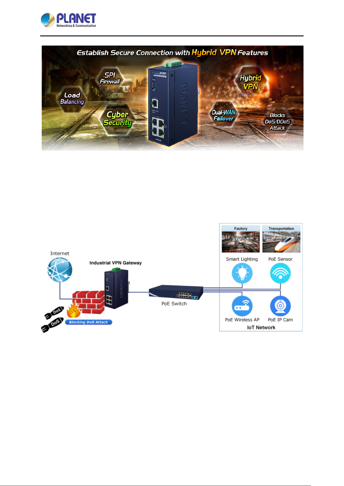
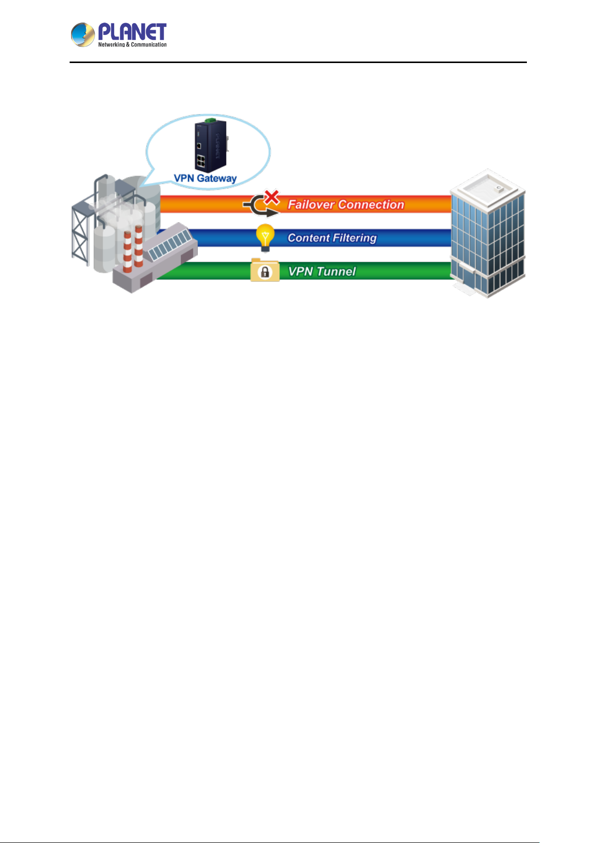
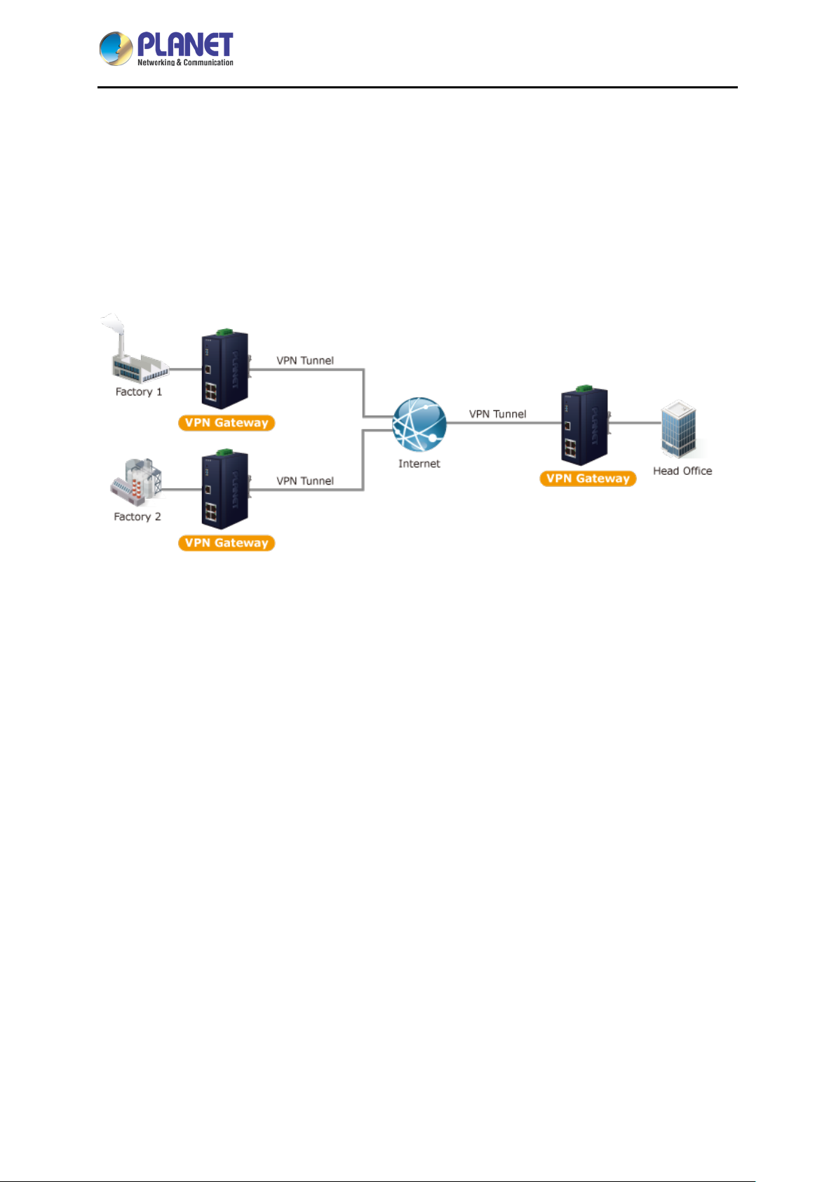
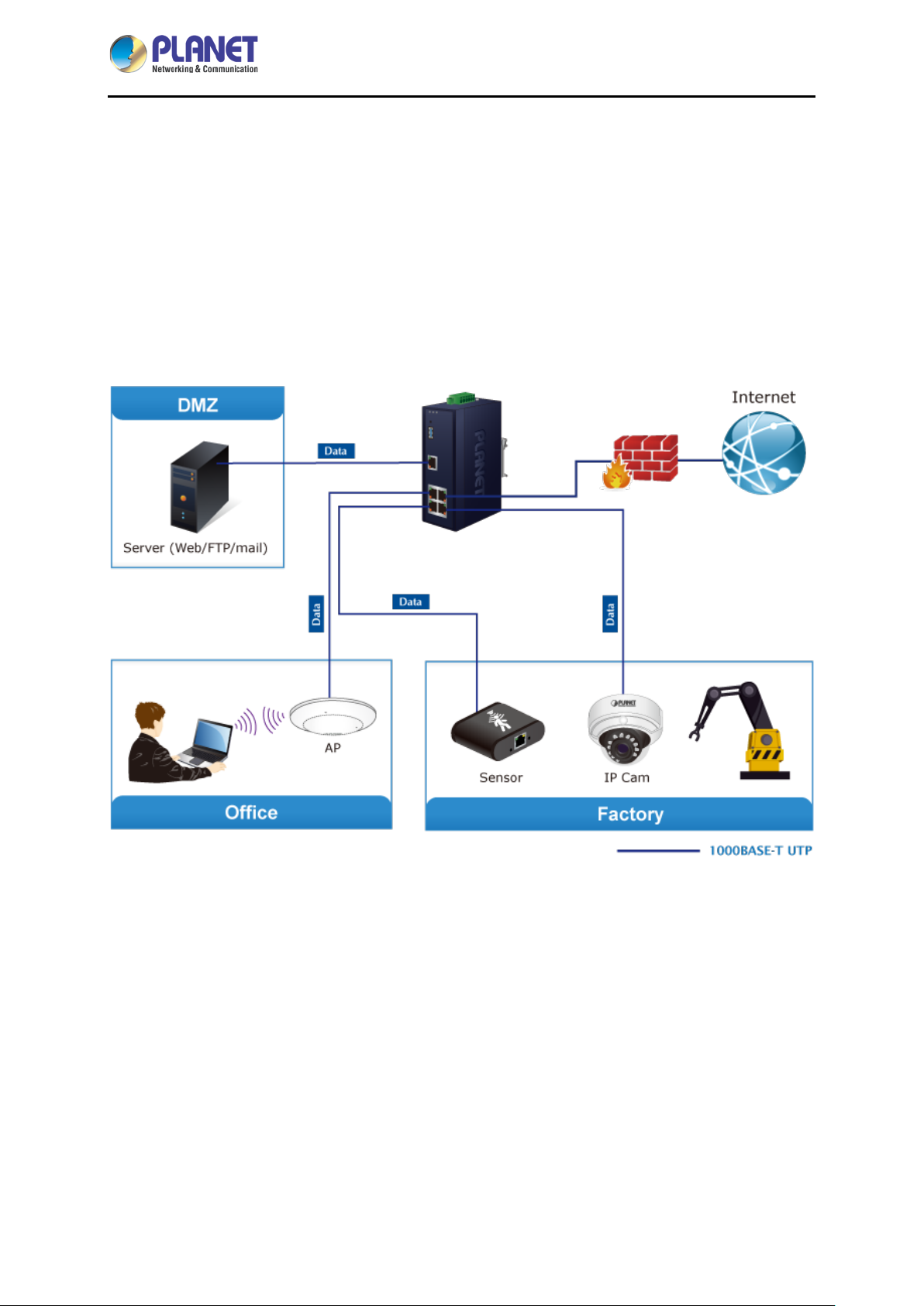
1.3 Topology
PLANET IVR-100 can work as a VPN security gateway in an industria l application f or a company that
has a factory and many different divisions. With IPSec/GRE/PPTP/L2TP/SSL VPN solutions, the
IVR-100 provides secured data communication for branches, vendors, and mobile workers with a
flexible way to connect back to the headquarters.
The IVR-100 connects dual WANs with up to two different ISPs. It creates a stable and qualified VPN
connection for many important applications such as VoIP, video conferencing and data transmission.
- 11 -
Page 12

Industrial 5-Port 10/100/1000T VPN Security Gateway
1.4 Features
Hardware
5 10/100/1000BASE-T RJ45 ports
1 undefined Ethernet port (LAN/WAN)
Dual-WAN function
1 USB 3.0 port for system configuration backup and firmware upgrade
Reset button
Industrial Case and Installation
IP30 metal case
Solid DIN-rail, wal l-mount or side wall-mount design
Supports 6KV DC Ethern et ESD protec t io n
IVR-100
Fault alarm for power input failure
DC redundant power with reverse polarity protection
-40 to 75 degrees C operating temperature
IP Routing Feature
Static Route
Dynamic Route (RIPv1/v2)
Firewall Security
Stateful Packet Inspection (SPI) firewall
Blocks DoS/DDoS attack
Content filtering
MAC/IP filtering
Blocks SYN/ICMP flooding
VPN Features
IPSec (Host to Host)/GRE/PPTP server/L2TP/SSL(Open VPN)
Max. Connection Tunnel Entries: 60 VPN tunnels,
Encryption methods: DES, 3DES, AES, AES-128/192/256
Authentication methods: MD5, SHA-1, SHA-256, SHA -384, SHA-512
Networking
Outbound load balancing
Failover for dual-WAN
- 12 -
Page 13

Industrial 5-Port 10/100/1000T VPN Security Gateway
Static IP/DHCP client for WAN
Protocols: TCP/IP, UDP, ARP, IPv4, IPv6
Port forwarding
QoS
DMZ
VLAN
IGMP Proxy
SNMP(v1/v2C/v3)
DHCP server/NTP client
MAC address clone
DDNS: PLANET DDNS, PLANET Easy DDNS, DynDNS and No-IP
Cybersecurity
Others
IVR-100
Setup wizard
Dashboard for real-time system overview
Supported access by HTTP or HTTPS
Auto reboot
Configuration backup and restoration via remote/USB port
Firmware upgrade via remote/USB port
Event message logging to remote syslog server
PLANET Smart Discovery utility/UNI-NMS supported
- 13 -
Page 14
Industrial 5-Port 10/100/1000T VPN Security Gateway
1.5 Product Specifications
IVR-100
Product
Model
Hardware
Ethernet
USB Port
Reset Button
Enclosure
LED Indicators
Installation
VPN security gateway
IVR-100
5 10/100/1000BASE-T RJ45 Ethernet ports including
3 LAN ports
1WAN port
1 LAN/WAN port
1 USB 3.0 port for system configuration backup and firmware upgrade
< 5 sec: System reboot
> 5 sec: Factory default
IP30 metal case
Power1/Power2 (Green)
Fault (Red)
DIN-rail, wall-mount or side wall-mount design
Removable 6-pin terminal block
Connector
Alarm
Power Requirements
Power Consumption
Weight
Dimensions (W x D x H)
ESD Protection
Software
Management
Operation Mode
Routing Protocol
Pin 1/2 for Power 1
Pin 3/4 for power fault alarm
Pin 5/6 for Po wer 2
One relay output for power failure.
Alarm relay current carry ability: 1A @ 24V AC
9-48V AC, 1A max.
9W max.
0.53kg
135 x 87.8 x 50 mm
6KV DC
Web browser
Routing mode
Static route: 32
Dynamic route (RIPv1/v2): 4096
NAT Throughput
Firewall Security
Outbound Load Balancing
Max. 900Mbps
Stateful packet inspection (SPI)
Blocks DoS/DDoS attack
Supported algorithms: Weight
- 14 -
Page 15
Industrial 5-Port 10/100/1000T VPN Security Gateway
HTTP, HTTPS, NTP, DNS, PLANET
PPPoE,
IVR-100
IPv4, IPv6, TCP/IP, U D P, AR P,
Protocol
Content Filtering
Log
Others
DDNS, PLANET Easy DDNS, DHCP, SNMP(v1/v2C/v3),
SNMP, QoS, VLAN, IGMP Proxy
MAC filtering
IP filtering
Web filtering
System operation log
Event message logging to remote syslog server
Outbound load balancing
Failover for dual-WAN
Port forwarding
DMZ
Cybersecurity
Dashboard
Setup wizard
Auto reboot
PLANET Smart Discovery utility/UNI-NMS supported
VPN
VPN Function
VPN Tunnels
VPN Throughput
VPN concurrent users
Encryption Methods
Authentication Methods
Standards Conformance
Regulatory Compliance
Stability Testing
IPSec (Host to Host)/GRE/PPTP server/L2TP/SSL (Open VPN)
Max. 60
Max. 100Mbps
Max. 60
DES, 3DES, AES or AES-128/192/256 encr ypting
MD5/SHA-1/SHA-256/SHA-384/SHA-512 authentication algorithm
CE, FCC
IEC60068-2-32 (free fall)
IEC60068-2-27 (shock)
IEC60068-2-6 (vibration)
IEEE 802.3 10BASE-T
IEEE 802.3u 100BASE-TX/100BASE-FX
IEEE 802.3ab Gigabit 1000T
Standards Compliance
IEEE 802.1Q VLAN tagging
RFC 768 UDP
RFC 791 IP
RFC 792 ICMP
RFC 2068 HTTP
- 15 -
Page 16

Industrial 5-Port 10/100/1000T VPN Security Gateway
Environment Specifications
IVR-100
Operating
Storage
Standard Accessories
Packet Contents
Temperature: -40 ~ 75 degrees C
Relative Humidity: 5 ~ 95% (non-condensing)
Temperature: -40 ~ 85 degrees C
Relative Humidity: 5 ~ 95% (non-condensing)
IVR-100 x 1
Quick Installation Guide x 1
Wall-mount Kit x 1
Dust Cap x 5
- 16 -
Page 17
Industrial 5-Port 10/100/1000T VPN Security Gateway
P1
P2
Lights to indicate that po wer input
“Blink” to indicate there is traffic on
Ports
Chapter 2. Hardware Introduction
2.1 Physical Descriptions
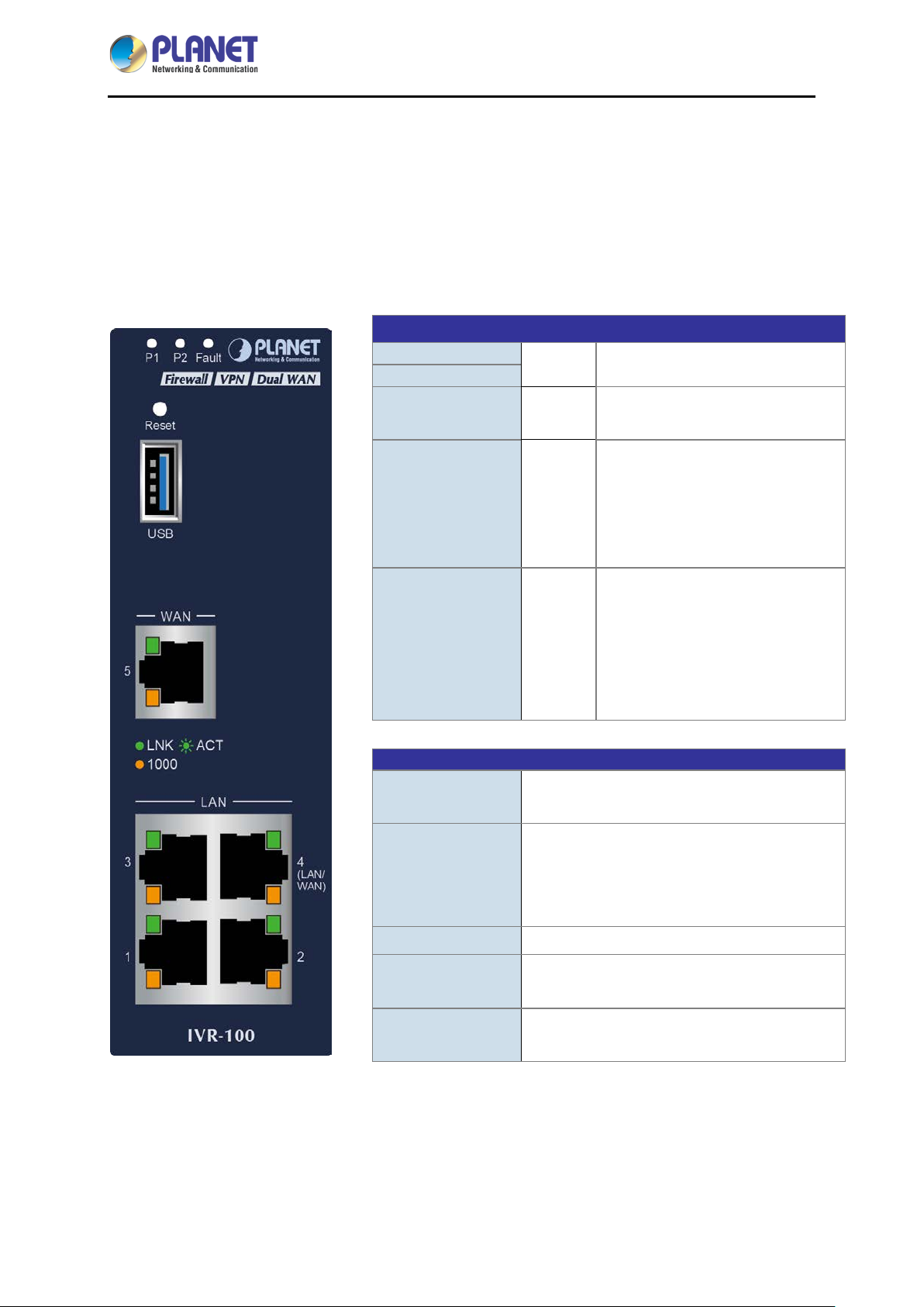
2.1.1 Front View
LED
IVR-100
Green
Fault
LNK / ACT Green
1000
USB Port
Red
Amber
USB 3.0 port for system configuration backup
and restoration.
Lights up when the power is on.
has failed.
“Steady on” to indicate the port is
connected to other network device
successfully.
the port.
“Steady on” to indicate that the
port is successfully connecting to
the network at 1000Mbps.
“Off” to indicate that the port is
successfully connecting to the
network at 10Mbps or 100Mbps.
Power on the device and press the reset
Reset Button
Gigabit Port 1-3 It is a LAN port for connecting to a switch.
Gigabit Port 4
Gigabit Port 5
- 17 -
button for less than 5 seconds to reboot it or
over 5 seconds to restore it to factory default
settings.
Default is LAN port. It can be defined as LAN
port or WAN port.
It is a WAN port for connecting to a perimeter
gateway.
Page 18
Industrial 5-Port 10/100/1000T VPN Security Gateway
IVR-100
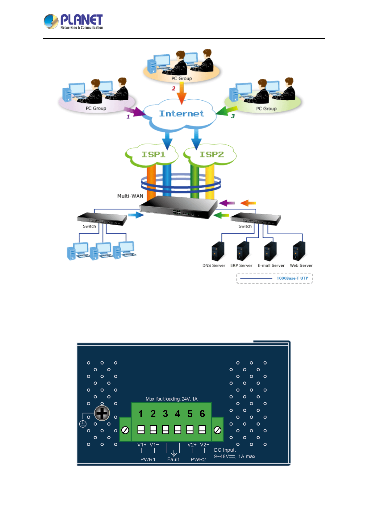
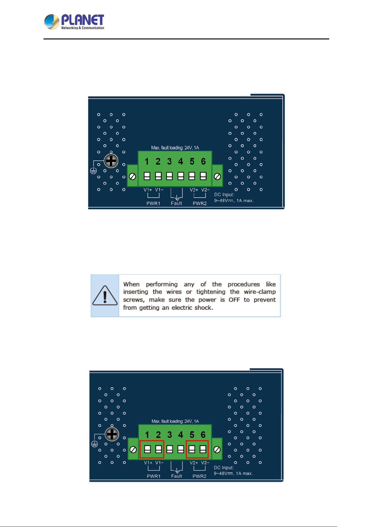
2.1.2 Top View
The upper panel of the Industrial Gateway consists of one terminal block connector within two DC
power inputs.
2.1.3 Wiring the Power Inputs
The 6-contact terminal block connector on the top panel of Industrial Gateway is used for two DC
redundant power inputs . Pl ease follow the steps below to insert the power wire.
1. Insert positive and negative DC power wires into contacts 1 and 2 for POWER 1, or 5 and 6 for
POWER 2.
- 18 -
Page 19
Industrial 5-Port 10/100/1000T VPN Security Gateway
To avoid damage, please use the Industrial Gateway under its
specification.
2. Tighten the wire-clamp screws for preventing the wires from loosening.
1 2 3 4 5 6
Power 1 Fault Power 2
IVR-100
+ - + -
The wire gauge for the terminal block should be in the range from 12 to 24 AWG.
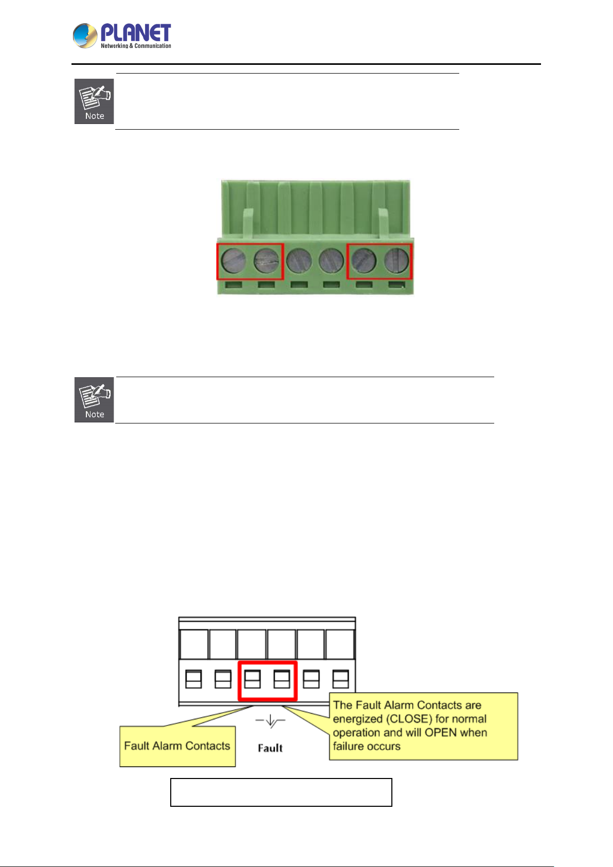
2.1.4 Wiring the Fault Alarm Contact
The fault alarm contacts are in the middle of the terminal block connector as the picture shows below.
Inserting the wires, the Industrial Gateway will detect the fault status of the power failure and then forms
an open circuit. The following illustration shows an application example for wiring the fault alarm
contacts.
1 2 3 4 5 6
Insert the wires into the fault alarm contacts
- 19 -
Page 20

Industrial 5-Port 10/100/1000T VPN Security Gateway
IVR-100
1. The wire gauge for the terminal block should be in the range between
12 and 24 AWG.
2. Alarm relay circuit accepts up to 24V, max. 1A currents.
- 20 -
Page 21
Industrial 5-Port 10/100/1000T VPN Security Gateway
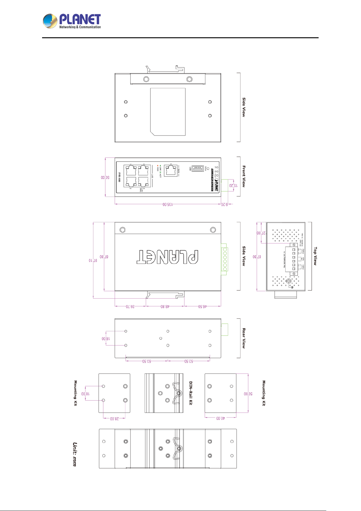
2.1.5 Dimensions
IVR-100
- 21 -
Page 22
Industrial 5-Port 10/100/1000T VPN Security Gateway
IVR-100
2.2 Hardware Installation
This section describes how to install the Industrial Gateway. There are three methods to install the
Industrial Gateway -- DIN-rail mounting, wall mounting and side wall mounting. Basic knowledge of
networking is assumed.
Please read the following sections and perform the procedures in the order being presented.
(The device shown on this chapter is just a representation of the said device.)
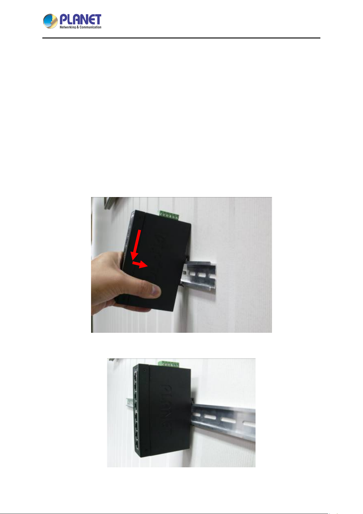
2.2.1 DIN-rail Mounting
Step 1: Lightly slide the DIN-rail into the track.
Step 2: Check whether the DIN-rail is tightly on the track.
- 22 -
Page 23

Industrial 5-Port 10/100/1000T VPN Security Gateway
IVR-100
Step 3: Connect your device to hub / switch.
A. Connect one end of a standard network cable to the LAN port (port 1) of the device.
B. Connect the other end of the cable to the hub / switch.
The UTP Category 5, 5e or 6 network cabling with RJ45 tips is recommended.
Step 4: Connect your device to internet.
A. Connect one end of a standard network cable to the WAN port (port 5) of the device.
B. Connect the other end of the cable to the LAN port of ISP network device (such as a modem).
If there is only one line connected to the outer network in your network environment, it is
suggested that you use WAN port (port 5).
Step 5: Power on the device. When the device receives power, the Power LED should remain solid
Green.
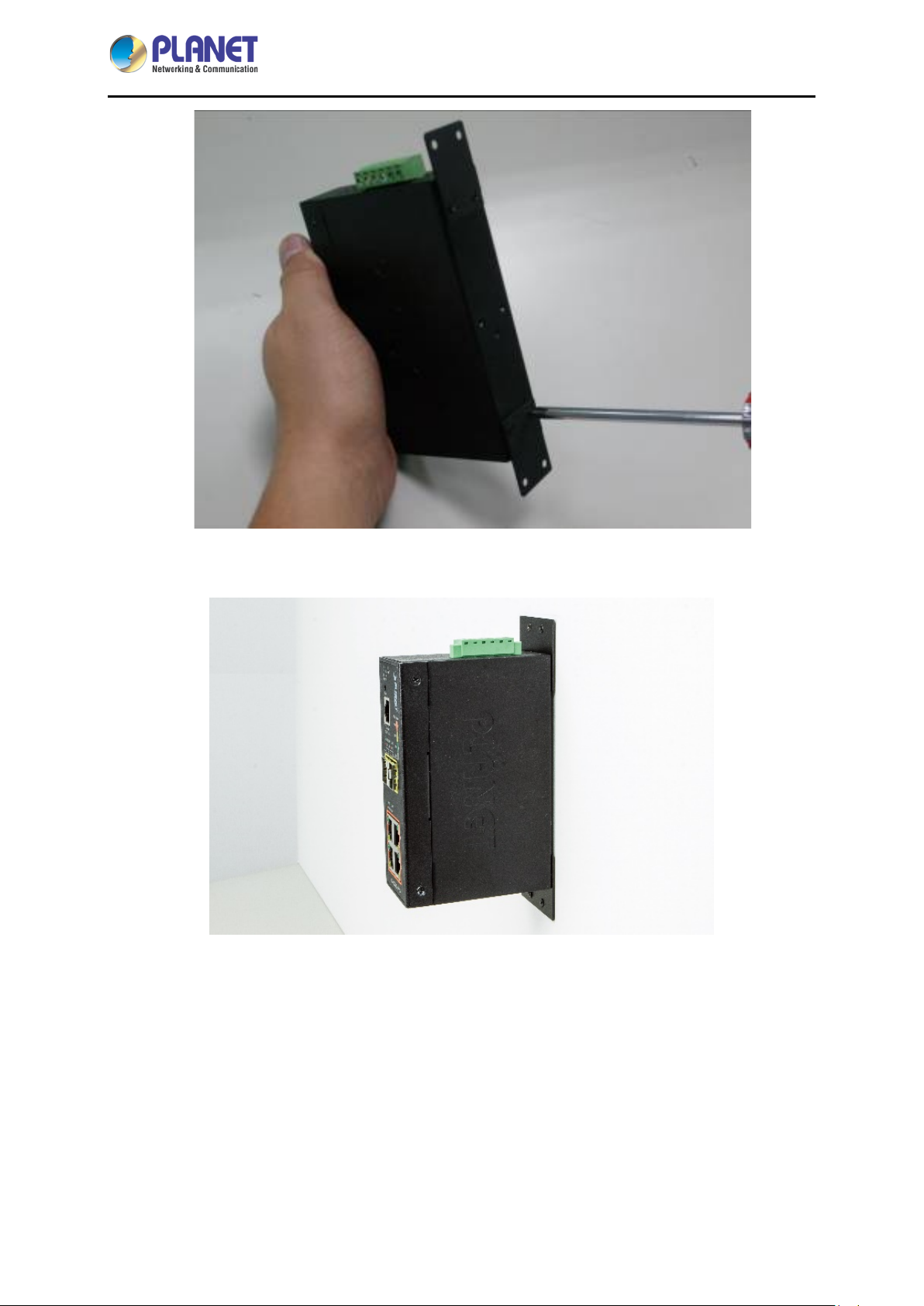
2.2.2 Wall Mount Plate Mounting
To install the Industrial Gateway on the wall, please follow the instructions below.
Step 1: Remove the DIN-rail from the Industrial Gateway. Use the screwdriver to loosen the screws to
remove the DIN-rail.
Step 2: Place the wall-mount plate on the rear panel and use the screwdriver to screw the wall mount
plate tightly on the Industrial Gateway.
- 23 -
Page 24
Industrial 5-Port 10/100/1000T VPN Security Gateway
IVR-100
Step 3: Use the hook holes at the corners of the wall mount plate to hang the Industrial Gateway on the
wall.
Step 4: To remove the wall mount plate, reverse the steps above.
Step 5: Proceed with Steps 3, 4 and 5 in Secti on 2.2.1 DIN-rail Mounting to connect the network
cabling and power on the device.
- 24 -
Page 25

Industrial 5-Port 10/100/1000T VPN Security Gateway
IVR-100
2.2.4 Side Wall Mount Plate Mounting
To install the Industrial Gateway on the wall, please follow the instructions below.
Step 1: Remove the DIN-rail from the Industrial Gateway. Use the screwdriver to loosen the screws to
remove the DIN-rail.
Step 2: Place the wall-mount plate on the side panel and use the screwdriver to screw the wall mount
plate tightly on the Industrial Gateway.
Step 3: Use the hook holes at the corners of the wall mount plate to hang the Industrial Gateway on the
wall.
Step 4: To remove the wall mount plate, reverse the steps above.
Step 5: Proceed with Steps 3, 4 and 5 in Section 2.2.1 DIN-rail Mounting to connect the network
cabling and power on the device.
- 25 -
Page 26
Industrial 5-Port 10/100/1000T VPN Security Gateway
IVR-100
Chapter 3. Preparation
Before getting into the device’s web UI, user has to check the network setting and configure PC’s IP
address.
3.1 Requirements
User is able to confirm the following items before configuration:
1. Please confirm the network is working properly; it is strongly suggested to test your network
connection by connecting your computer directly to ISP.
2. Suggested operating systems: Windows 7 / 8 / 10.
3. Recommended web browsers: IE / Firefox / Chrome.
3.2 Setting TCP/IP on your PC
The default IP address of the VPN Gateway is 192.168.1.1, and the DHCP Server is on. Please set the
IP address of the connected PC as DHCP client, and the PC will get IP address automatically from the
VPN Gateway.
Please refer to the following to set the IP address of the conn ect ed PC.
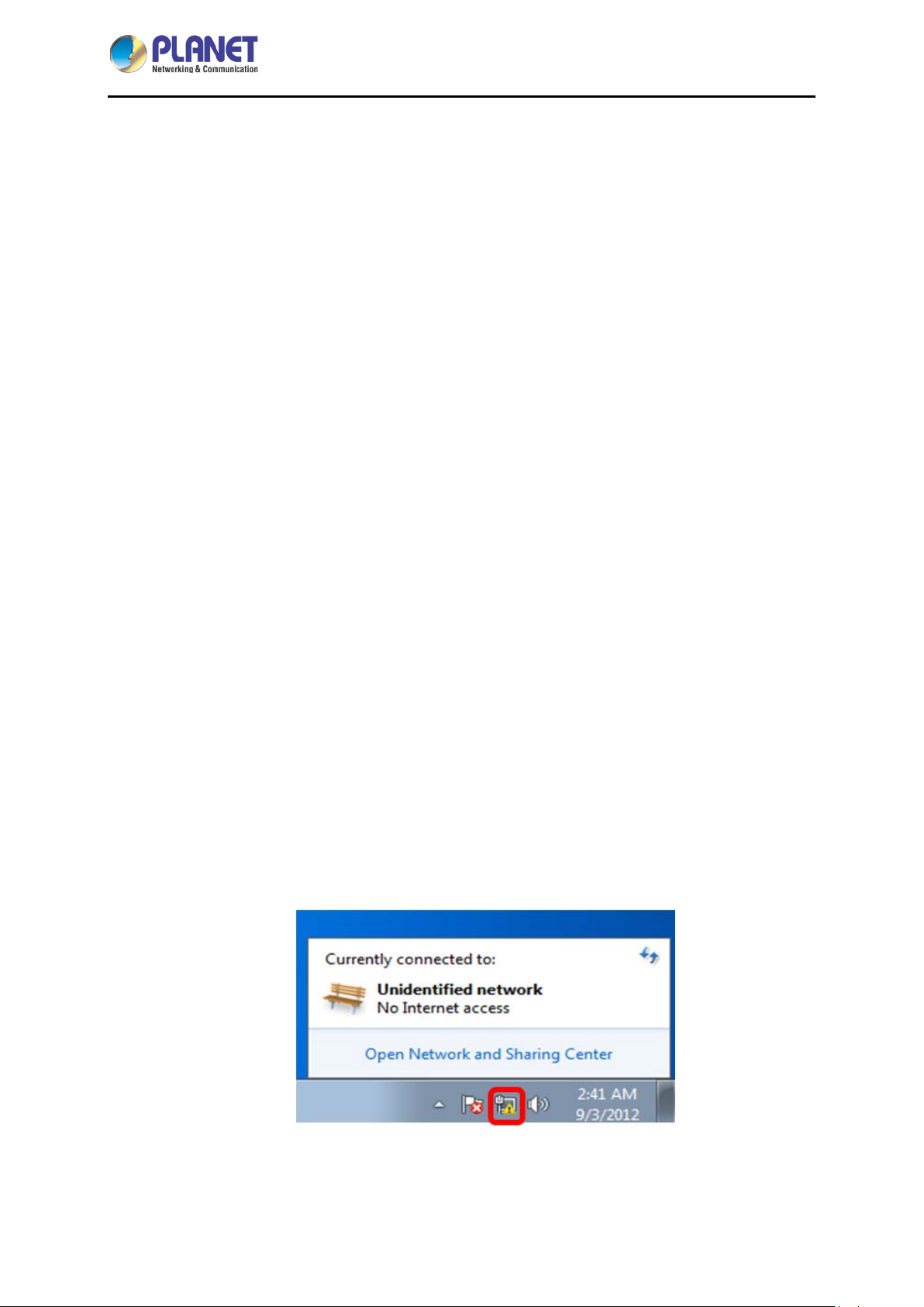
3.2.1 Wind ows 7/8
If you are using Windows 7/8, please refer to the following:
1. Click on the network icon from the right side of the taskbar and th en click on “Open Net work and
Sharing Center”.
- 26 -
Page 27
Industrial 5-Port 10/100/1000T VPN Security Gateway
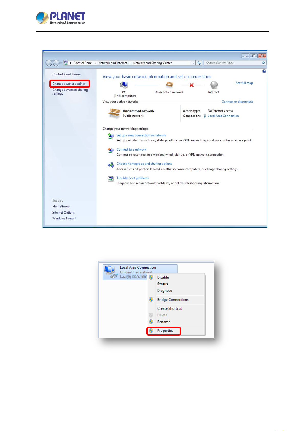
2. Click "Change adapter settings".
IVR-100
3. Right-click on the Local Area Connection and select Properties.
- 27 -
Page 28
Industrial 5-Port 10/100/1000T VPN Security Gateway
IVR-100
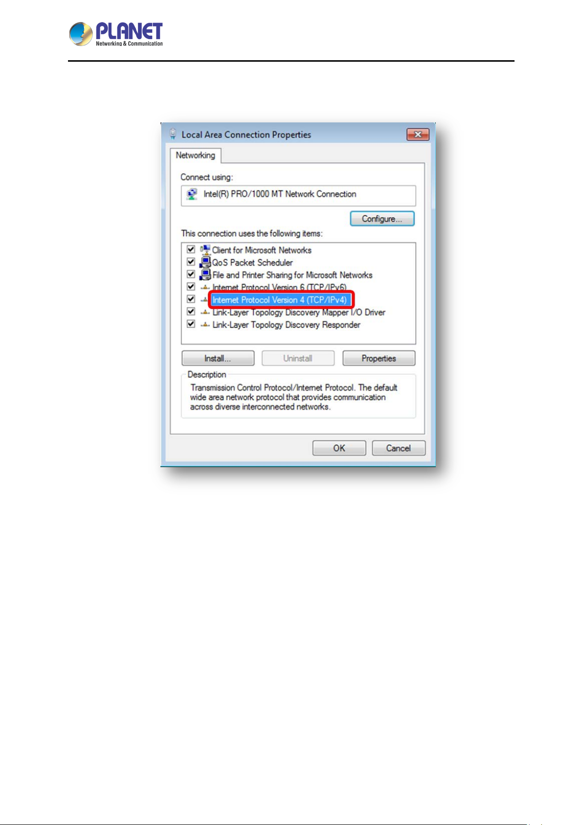
4. Select Internet Protocol Version 4 (TCP/IPv4) and click Properties or directly double-click on
Internet Protocol Version 4 (TCP/IPv4).
- 28 -
Page 29

Industrial 5-Port 10/100/1000T VPN Security Gateway
IVR-100
5. Select "Use the following IP address" and "Obtain DNS server address automatically", and
then click the “OK” button.
- 29 -
Page 30

Industrial 5-Port 10/100/1000T VPN Security Gateway
IVR-100
3.2.2 Windows 10
If you are using Windows 10, please refer to the following:
1. In the se arch box on the taskbar, type “View network connec tions”, and then select View net work
connections at the top of the list.
- 30 -
Page 31

Industrial 5-Port 10/100/1000T VPN Security Gateway
2. Right-click on the Local Area Connection and select Properties.
IVR-100
3. Select Internet Protocol Version 4 (TCP/IPv4) and click Properties or directly double-click on
Internet Protocol Version 4 (TCP/IPv4).
- 31 -
Page 32

Industrial 5-Port 10/100/1000T VPN Security Gateway
IVR-100
4. Select "Use the following IP address" and "Obtain DNS server address automatically", and
then click the “OK” button.
- 32 -
Page 33

Industrial 5-Port 10/100/1000T VPN Security Gateway
IVR-100
3.3 Planet Smart Discovery Utility
For easily listing the Gateway in your Ethernet environment, the search tool -- Planet Smart Discovery
Utility -- is an ideal solution.
The following installation instructions are to guide you to running the Planet Smart Discovery Utility.
1. Download the Planet Smart Discovery Utility in administrator PC.
2. Run this utility as the following screen appears.
Figure 3-1-6: Planet Smart Discovery Utility Screen
If there are two LAN car ds or above in th e same adm inistrator PC, choose a d ifferent
LAN card by using the “Select Adapter” tool.
3. Press the “Refresh” button for the currently connected devices in the discovery list as the screen
shows below:
Figure 3-1-7: Planet Smart Discovery Utility Screen
- 33 -
Page 34

Industrial 5-Port 10/100/1000T VPN Security Gateway
IVR-100
1. This utility shows all necessary information from the devices, such as MAC address, device name,
firmware version, and device IP subnet address. It can also assign new password, IP subnet
address and description to the devices.
2. After setup is completed, press the “Update Device”, “Update Multi” or “Update A ll” button to take
effect. The functions of the 3 buttons above are shown below:
Update Device: use current setting on one single device.
Update Multi: use current setting on choose multi-devices.
Update All: use current setting on whole devices in the list.
The same functions mentioned above also can be found in “Option” tools bar.
3. To click the “Control Packet Force Broadcast” function, it allows you to assign a new setting
value to the device under a different IP subnet address.
4. Press the “Connect to Device” button and the Web login screen appears.
Press the “Exit” button to shut down the Planet Smart Discovery Utility.
- 34 -
Page 35

Industrial 5-Port 10/100/1000T VPN Security Gateway
IVR-100
Chapter 4. Web-based Management
This chapter provides setup details of the device’s Web-based Interface.
4.1 Introduction
The device can be configured with your Web browser. Before configuring, please make sure your PC is
under the same IP segment with the device.
4.2 Logging in to the VPN Gateway
Refer to the steps below to configure the VPN Gateway:
Step 1. Connect the IT administrat or ’s PC and VPN Gateway’s LAN por t (port 1) to the s ame hub /
switch, and then launc h a b r owser t o link the managem ent inter f ac e a ddres s whi c h is s et to
http://192.168.1.1 by default.
The DHCP server of the VPN Gateway is enabled. Therefore, the LAN PC
will get IP from the VPN Gateway. If user needs to set IP address of LAN
PC manually, please set the IP address within the range between
192.168.1.2 and 192.168.1.254 inclusively, and assigned the subnet mask
of 255.255.255.0.
Step 2. The browser prompts you for the login credentials. (Both are “admin” by default.)
Default IP address: 192.168.1.1
Default user name: admin
Default password: admin
Administrators are strongly suggested to change the default admin and
password to ensure system security.
- 35 -
Page 36

Industrial 5-Port 10/100/1000T VPN Security Gateway
Object
Icon
Function
IVR-100
4.3 Main Web Page
After a successful login, the main web page appears. The web main page displays the web panel, main
menu, function menu, and the main information in the center.
Figure 4-1: Main Web Page
■ Web Panel
The web panel displays an image of the device’s ports as shown in Figure 4-2.
Figure 4-2: Web Panel
To indicate the port without the RJ45 plug-in.
Ethernet port
To indicate network data is sending or receiving
- 36 -
Page 37

Industrial 5-Port 10/100/1000T VPN Security Gateway
IVR-100
■ Main Menu
The main menu displays the product name, function menu, and main information in the center. Via the
Web management, the administrator can set up the device by selecting the functions those listed in the
function menu and button as shown in Figures 4-3 and 4-4.
Figure 4-3: Function Menu
Object Description
System
Network
Security
VPN
Maintenance
Provides System information of the Gateway.
Provides WAN, LAN and network configuration of the Gateway.
Provides Firewall and security configuration of the Gateway.
Provides VPN configuration of the Gateway.
Provides firmware upgrade and setting file restore/backup
configuration of the Gateway.
Figure 4-4: Function Button
Object Description
Click the "Refresh button" to refresh the current web page.
Click the "Logout button" to log out the web UI of the Gateway.
- 37 -
Page 38

Industrial 5-Port 10/100/1000T VPN Security Gateway
IVR-100
4.4 System
Use the System menu items to display and configure basic administrative details of the Gateway. The
System menu shown in Figure 4-5 provides the following features to configure and monitor system.
Object Description
Wizard
Dashboard
Status
Statistics
Connection Status
SNMP
Figure 4-5: System Menu
The Wizard will guide the user to configuring the Gateway easily
and quickly.
The overview of system information includes connection, port,
and system status.
Display the status of the system, LAN and WAN.
Display statistics information of network traffic of LAN and WAN.
Display the DHCP client table and the ARP table.
Display SNMP system information.
- 38 -
Page 39

Industrial 5-Port 10/100/1000T VPN Security Gateway
IVR-100
4.4.1 Setup Wizard
The Wizard will guide the user to configuring the Gateway easily and quickly. There are different
procedures in different operation modes. According to the operation mode you switch to, please follow
the instructions below to configure the Gateway via Setup Wizard as shown in Figure 4-6.
Figure 4-6: Setup Wizard
Step 1: LAN Interface
Set up the IP Address and Subnet Mask for the LAN interface as shown in Figure 4-7.
Figure 4-7: Setup Wizard – LAN Configuration
Object Description
IP Address
Subnet Mask
DHCP Server
Enter the IP address of your Gateway. The default is 192.168.1.1.
An address code that determines the size of the network. Normally
use 255.255.255.0 as the subnet mask.
By default, the DHCP Server is enabled.
If user needs to disable the function, please uncheck the box.
- 39 -
Page 40

Industrial 5-Port 10/100/1000T VPN Security Gateway
IVR-100
Start IP Address
By default, the start IP address is 192.168.1.100.
Please do not set it to the same IP address of the Gateway.
By default, the maximum DHCP users are 101, whi c h mean the
Maximum DHCP Users
Gateway will provide DHCP clie n t w ith IP address from 192.168.1.100
to 192.168.1.200 when the start IP address is 192.168.1.100.
Next
Press this button to the next step.
Press this button to undo any changes made locally and revert to
Cancel
previously saved values.
Step 2: WAN Interface
The Gateway supports two access modes on the WAN side shown in Figure 4-8
Figure 4-8: Setup Wizard – WAN 1 Configuration
- 40 -
Page 41

Mode 1 -- Static IP
Industrial 5-Port 10/100/1000T VPN Security Gateway
IVR-100
Figure 4-9: Setup Wizard – WAN 2 Configurations
Select Static IP Address if all the Internet port’s IP information is provided to you by your ISP. You will
need to enter the IP Address, Netmask, Default Gateway and DNS Ser v er provided to you by your
ISP. Each IP address entered in the fields must be in the appropriate IP form, which are four octets
separated by a dot (x.x.x.x). The Gateway will not accept the IP address if it is not in this format. The
setup is shown in Figure 4-10.
Figure 4-10: WAN Interface Setup – Static IP Setup
Object Description
IP Address
Netmask
Default Gateway
DNS Server
Enter the IP address assigned by your ISP.
Enter the Netmask assigned by your ISP.
Enter the Gateway assigned by your ISP.
The DNS server information will be supplied by your ISP.
- 41 -
Page 42

Industrial 5-Port 10/100/1000T VPN Security Gateway
IVR-100
Next
Previous
Press this button for the next step.
Press this button for the previous step.
Press this button to undo any changes made locally and revert
Cancel
to previously saved values.
Mode 2 -- DHCP Client
Select DHCP Client to obtain IP Address information automatically from your ISP . The setup is shown in
Figure 4-11.
Figure 4-11: WAN Interface Setup – DHCP Setup
Step 3: Security Setting
Set up the Securit y Settings as shown in Figur e 4-12.
Figure 4-12: Setup Wizard –Security Setting
- 42 -
Page 43

Industrial 5-Port 10/100/1000T VPN Security Gateway
Object
Description
IVR-100
The SPI Firewall prevents attack and improper access to network
SPI Firewall
Block SYN Flood
Block ICMP Flood
Block WAN Ping
Remote Management
resources.
The default configuration is enabled.
SYN Flood is a popular attack way. DoS and DDoS are TCP
protocols. Hackers like using this method to make a fake connection
that involves the CPU, memory, and so on.
The default configuration is enabled.
ICMP is kind of a pack of TCP/IP; its important function is to transfer
simple signal on the Internet. There are two normal attack ways
which hackers like to use, Ping of Death and Smurf attack.
The default configuration is disabled.
Enable the function to allow the Ping access from the Internet
network.
The default configuration is disabled.
Enable the function to allow the web server access of the Gateway
from the Internet network.
The default configuration is disabled.
Next
Previous
Press this button for the next step.
Press this button for the previous step.
Press this button to undo any changes made locally and revert to
Cancel
previously saved values.
Step 4: Setup Completed
The page will show the summary of LAN, WAN and Security settings as shown in Figure 4-13.
- 43 -
Page 44

Industrial 5-Port 10/100/1000T VPN Security Gateway
Object
Description
IVR-100
Figure 4-13: Setup Wizard –Setup Completed
Finish
Previous
Press this button to save and apply changes.
Press this button for the previous step.
- 44 -
Page 45

Industrial 5-Port 10/100/1000T VPN Security Gateway
IVR-100
4.4.2 Dashboard
The dashboard provides an overview of system information including connection, port, and system
status as shown in Figure 4-14.
WAN/LAN Connection Status
Object Description
Port Status
Figure 4-14: Dashboard
The status means WAN is connected to Internet and LAN is
connected.
The status means WAN is disconnected to Internet and LAN
is connected.
The status means WAN is connected to Internet and LAN is
disconnected.
- 45 -
Page 46
Industrial 5-Port 10/100/1000T VPN Security Gateway
Object Description
IVR-100
System Information
Object Description
CPU Display the CPU loading
Memory Display the memory usage
Ethernet port is in use.
Ethernet port is not in use.
USB port is in use.
USB port is not in use.
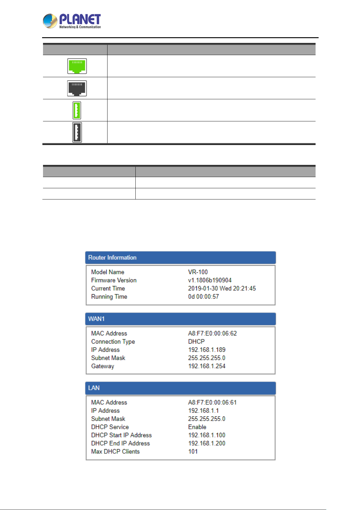
4.4.3 Status
This page displays system information as shown in Figure 4-15.
Figure 4-15: Status
- 46 -
Page 47

Industrial 5-Port 10/100/1000T VPN Security Gateway
IVR-100
4.4.4 Statistics
This page displays the number of packets that pass through the Gateway on the WAN and LAN. The
statistics are shown in Figure 4-16.
Figure 4-16: Statistics
4.4.5 Connection Sta t us
The page will show the DHCP T able and ARP T able. .
Figure 4-17: Connection Status
- 47 -
Page 48

Industrial 5-Port 10/100/1000T VPN Security Gateway
4.4.6 SNMP
This page provides SNMP setting of the Gateway as shown in Figure 4-18.
IVR-100
Object Description
Enable SNMP
Read/Write Community
System Name
System Location
System Contact
Apply Settings
Cancel Changes
Figure 4-18: SNMP
Disable or enable the SNMP function.
The default configuration is enabled.
Allows entering characters for SNMP Read/Write Community of the
Gateway.
Allows entering character s f or system name of the Gateway.
Allows entering character s f or system location of the Gateway.
Allows entering character s f or system contact of the Gateway.
Press this button to save and apply changes.
Press this button to undo any changes made locally and revert to
previously saved values.
- 48 -
Page 49
Industrial 5-Port 10/100/1000T VPN Security Gateway
Object
Description
IVR-100
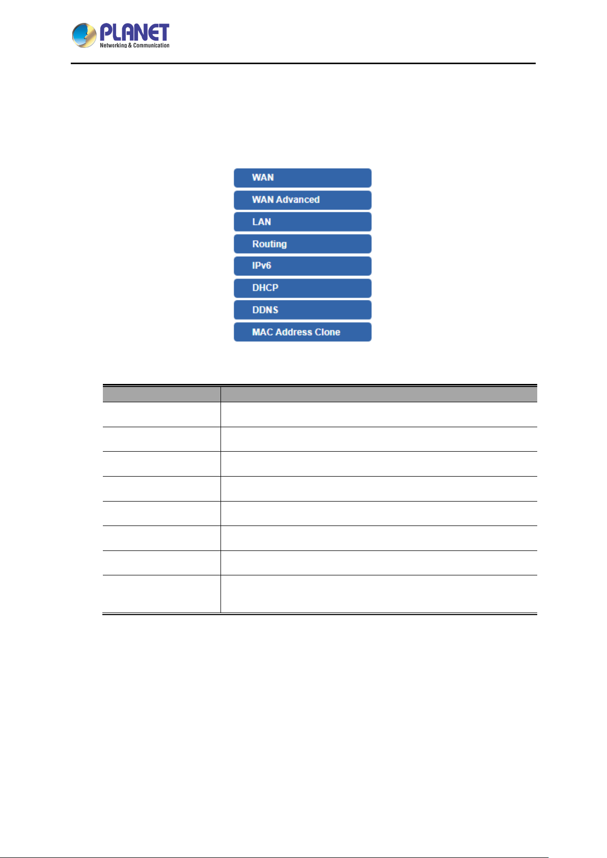
4.5 Network
The Network function provides WAN, LAN and network configuration of the Gateway as shown in
Figure 4-19.
Figure 4-19: Network Menu
WAN Setup
WAN A dvanced
LAN Setup
Routing
IPv6
DHCP
DDNS
MAC Address
Clone
Allows setting WAN interface.
Allows setting WAN Advanced settings.
Allows setting LAN interface.
Allows setting Route.
Allows setting IPv6 WAN interface.
Allows setting DHCP Server.
Allows setting DDNS and PLANET DDNS.
Allows setting WAN MAC Address Clone.
- 49 -
Page 50
Industrial 5-Port 10/100/1000T VPN Security Gateway
Object
Description
IVR-100
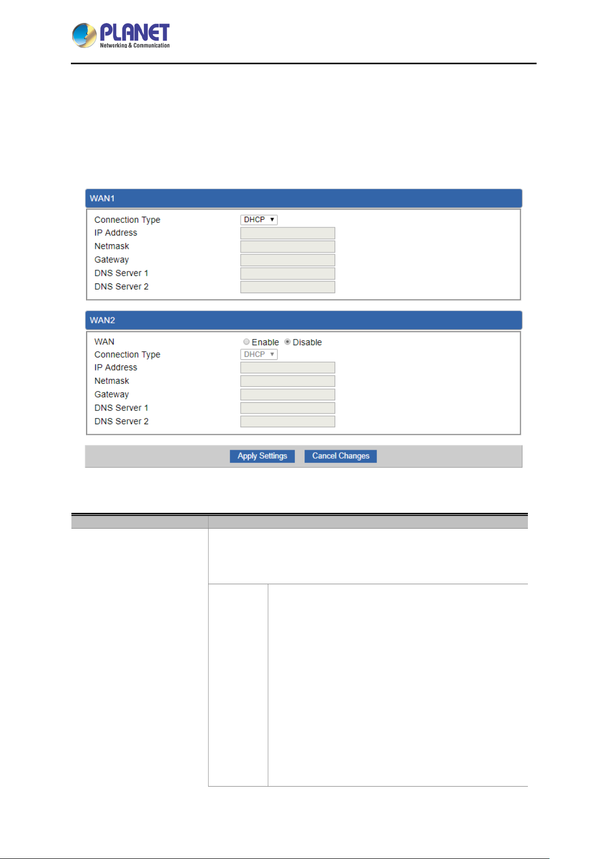
4.5.1 WAN
This page is used to configure the parameters for Internet network which connects to the WAN port of
the Gateway as shown in Figure 4-20. Here you may select the access method by clicking the item
value of WAN access type.
WAN Acces s Ty p e
Figure 4-20: WAN
Please select the corresponding WAN Access Ty pe for the Internet,
and fill out the correct parameters from your local ISP in the fields
which appear below.
Select Static IP Address if all the Internet ports’ IP
information is provided to you by your ISP (Internet
Service Provider). You will need to enter the IP
address, Netmask, Gateway, and DNS Server provided
to you by your IS P.
Static
Each IP address entered in the fields must be in the
appropriate IP form, which are four octets separated by
a dot (x.x.x.x). The Gateway will not accept the IP
address if it is not in this format.
IP Address
Enter the IP address assigned by your ISP.
- 50 -
Page 51

Industrial 5-Port 10/100/1000T VPN Security Gateway
Object
Description
IVR-100
Netmask
Enter the Subnet Mask assigned by your ISP.
Gateway
Enter the Gateway assigned by your ISP.
DNS Server
The DNS server information will be supplied by your
ISP.
DHCP
WAN IP, whether obtained automatically or specified manually, should NOT be on
the same IP net segment as the LAN IP; otherwise, the Gateway will not work
properly. In case of emergency, press the hardware-based "Reset" button.
Select DHCP Client to obtain IP Address information
automatically from your ISP.
4.5.2 WAN A dvan ced
This page is used to configure the advanced parameters for Internet area network which connects to
the WAN port of your Gateway as shown in Figure 4-21. Here you may change the setting for Load
Balance Weight, Detect Interval, Detect Link Up Threshold, etc...
Figure 4-21: LAN Setup
- 51 -
Page 52

Industrial 5-Port 10/100/1000T VPN Security Gateway
Object
Description
IVR-100
Load Balance Weight
External Connection
Detection
Detect Interval
Detect Link Up
Threshold
Detect Link Down
Threshold
Custom Detect Host
4.5.3 LAN Setup
Load Balance Weight allows you to set a relative weight (from 1 - 10)
for each WAN port.
Enable to detect the status of WAN connection.
Set the detect interval as you need.
The recommended value is 5 (default).
Set the times for detecting link up.
The recommended value is 8 (default).
Set the times for detecting link down.
The recommended value is 3 (default).
The host is used to check whether the internet connection is alive or
not.
This page is used to configure the parameters for local area network which connects to the LAN port of
your Gateway as shown i n Figure 4-22. Here you may change the settings for IP address, subnet mask,
DHCP, etc.
Figure 4-22: LAN Setup
Object Description
IP Address The LAN IP address of the Gateway and default is 192.168.1.1.
Net Mask Default is 255.255.255.0.
- 52 -
Page 53

Industrial 5-Port 10/100/1000T VPN Security Gateway
Object
Description
4.5.4 Routing
Please refer to the following sections for the details as shown in Figures 4-23 and 24.
Figure 4-23: Routing table
IVR-100
Figure 4-24: Routing setup
Routing tables contain a list of IP addresses. Each IP address identifies a remote router (or other
network gateway) that the local router is configured to recognize. For each IP address, the routing table
additionally stores a network mask and other data that specifies the destination IP address ranges that
remote device will accept.
Type
Destination
Net Mask
There are two types: Host and Net.
When the Net type is selected, user does not need to input the
Gateway.
The network or host IP address desired to access.
The subnet mask of destination IP.
- 53 -
Page 54

Industrial 5-Port 10/100/1000T VPN Security Gateway
Object
Description
Object
Description
IVR-100
The gateway is the router or host’s IP address to which packet was
Gateway
Interface
Comment
sent. It must be the same network segment with the WAN or LAN
port.
Select the interface that the IP packet must use to transmit out of the
router when this route is used.
Enter any words for recognition.
4.5.5 WAN IPv6 Setting
This page is used to configure parameter for IPv6 internet network which connects to WAN port of the
Gateway as shown in Figure 4-25. It allows you to enable IPv6 function and set up the parameters of
the Gateway’s WAN. In this setting you may change WAN connection type and other settings.
Connection Type
IPv6 Address
Subnet Prefix Length
Default Gateway
Figure 4-25: IPv6 WAN setup
Select IPv6 WAN type either by using DHCP or Static.
Enter the WAN IPv6 address.
Enter the subnet prefix length.
Enter the default gateway of the WAN port.
- 54 -
Page 55

Industrial 5-Port 10/100/1000T VPN Security Gateway
Object
Description
IVR-100
4.5.6 DHCP
The DHCP service allows you to control the IP address configuration of all your network devices. When
a client (host or other device such as networked printer, etc.) joins your network it will automatically get
a valid IP address from a range of addresses and other settings from the DHCP service. The client
must be configured to use DHCP; this is something called "automatic network configuration" and is
often the default setting. The setup is shown in Figure 4-26.
DHCP Service
Start IP Address
Maximum DHCP Users
Set DNS
Figure 4-26: DHCP
By default, the DHCP Server is enabled, meaning the Gateway will
assign IP addresses to the DHCP clients automatically.
If user needs to disable the function, please set it as disable.
By default, the start IP address is 192.168.1.100.
Please do not set it to the same IP address of the Gateway.
By default, the maximum DHCP users are 101, meaning the
Gateway will provide DHCP client with IP address from
192.168.1.100 to 192.168.1.200 when the start IP address is
192.168.1.100.
By default, it is set as Automatically, and the DNS server is the
Gateway’s LAN IP address.
If user needs to use specific DNS server, please set it as Manually,
Primary/Secondary DNS
Server
WINS
and then input a specific DNS server.
Input a specific DNS server.
Input a WINS server if needed.
- 55 -
Page 56

Industrial 5-Port 10/100/1000T VPN Security Gateway
Object
Description
IVR-100
Set the time for using one assigned IP. After the lease time, the
Lease Time
Domain Name
DHCP client will need to get new IP addresses from the Gateway.
Default is 1440 minutes.
Input a domain name for the Gateway.
Default is Planet.
- 56 -
Page 57

Industrial 5-Port 10/100/1000T VPN Security Gateway
IVR-100
4.5.7 DDNS
The Gateway offers the DDNS (Dynamic Domain Name System) feature, which allows the hosting of a
website, FTP server, or e-mail server with a fixed domain name (named by yourself) and a dynamic IP
address, and then your friends can connect to your server by entering your domain name no matter
what your IP address is. Before using this feature, you need to sign up for DDNS service providers such
as PLANET DDNS (http://www.planetddns.com
PLANET DDNS website provides a free DDNS (Dynamic Domain Name Server) service for PLANET
devices. Whether the IP address used on your PLANET device supporting DDNS service is fixed or
dynamic, you can easily connect the devices anywhere on the Internet with a meaningful or
easy-to-remember name you gave. PLANET DDNS provides two types of DDNS services. One is
PLANET DDNS and the other is PLANET Easy DDNS as shown in Figure 4-27.
PLANET DDNS
For example, you've just installed a PLANET IP camera with dynamic IP like 210.66.155.93 in the
network. You can name this device as “Mycam1” and register a domain as Mycam1.planetddns.com at
PLANET DDNS (http://www.planetddns.com
but just the URL link: Mycam1.planetddns.com.
PLANET Easy DDNS
PLANET Easy DDNS is an easy way to help user to get your Domain Name with just one click. Y ou can
just log in to the Web Management Interface of your devices, say, your Gateway, and check the DDNS
) and set up the domain name of your choice.
). Thus, you don't need to memorize the exact IP address
menu and just enable it. You don’t need to go to http://www.planetddns.com
Once you enabled the Easy DDNS, your PLANET Network Device will use the format PLxxxxxx where
xxxxxx is the last 6 characters of your MAC address that can be found on the Web page or bottom label
of the device. (For example, if the Gateway’s MAC address is A8-F7-E0-81-96-C9, it will be converted
into pt8196c9.planetddns.com)
Figure 4-27: PLANET DDNS
to apply for a new account.
- 57 -
Page 58

Industrial 5-Port 10/100/1000T VPN Security Gateway
Object
Description
When this function is enabled, DDNS hostname will appear
IVR-100
DDNS Service
Interface
DDNS Type
Easy DDNS
User Name
By default, the DDNS service is disabled.
If user needs to enable the function, please set it as enable.
User is able to select the interface for DDNS service.
By default, the interface is WAN 1.
There are three options:
1. PLANET DDNS: Activate PLANET DDNS service.
2. DynDNS: Activate DynDNS service.
3. NOIP: Activate NOIP service.
Note that please first register w ith the DDNS service and set up the
domain name of your choice to begin using it.
When the PLANET DDNS service is activated, user is able to s elect
to enable or disable Easy DDNS.
automatically. User doesn’t go to http://www.planetddns.com to
apply for a new account.
The user name is used to log into DDNS service.
Password
Host Name
Interval
Update Status
The password is used to log into DDNS service.
The host name as registered with your DDNS provider.
Set the update interval of the DDNS function.
Show the connection status of the DDNS function.
- 58 -
Page 59

Industrial 5-Port 10/100/1000T VPN Security Gateway
Object
Description
4.5.8 MAC Address Clone
Clone or change the MAC address of the WAN interface. The setup is shown in Figure 4-28.
IVR-100
Clone WAN MAC
MAC Address
Figure 4-28: MAC Address Clone
Set the function as enable or disable.
Input a MAC Address, such as A8:F7:E0:00:06:62.
- 59 -
Page 60

Industrial 5-Port 10/100/1000T VPN Security Gateway
Object
Description
IVR-100
4.6 Security
The Security menu provides Firewall, Access Filtering and other functions as shown in Figure 4-29.
Please refer to the following sections for the details.
Figure 4-29: Security menu
Firewall
MAC Filtering
IP Filtering
Web Filtering
Port Range
Forwarding
DMZ
Allows setting DoS (Denial of Service) protection as enable.
Allows setting MAC Filtering.
Allows setting IP Filtering.
Allows setting Web Filtering.
Allows setting Port Forwarding.
Allows setting DMZ.
- 60 -
Page 61

Industrial 5-Port 10/100/1000T VPN Security Gateway
Object
Description
IVR-100
4.6.1 Firewall
A "Denial-of-Service" (DoS) attack is characterized by an explicit attempt by hackers to prevent
legitimate users of a service from using that service. The Gateway can prevent specific DoS attacks as
shown in Figure 4-30.
SPI Firewall
Block SYN Flood
Block FIN Flood
Figure 4-30: Firewall
The SPI Firewall prevents attack and improper access to network
resources.
The default configuration is enabled.
SYN Flood is a popular attack way. DoS and DDoS are TCP
protocols. Hackers like using this method to make a fake connection
that involves the CPU, memory, and so on.
The default configuration is enabled.
If the function is enabled, when the number of the current FIN
packets is beyond the set value, the Gateway will start the blocking
function immediately.
The default configuration is disabled.
- 61 -
Page 62

Industrial 5-Port 10/100/1000T VPN Security Gateway
IVR-100
If the function is enabled, when the number of the current
Block UDP Flood
Block ICMP Flood
IP TearDrop
Ping Of Death
Block WAN Ping
UPD-FLOOD packets is beyond the set value, the Gateway will start
the blocking function immediately.
The default configuration is disabled.
ICMP is kind of a pack of TCP/IP; its important function is to transfer
simple signal on the Internet. There are two normal attack ways
which hackers like to use, Ping of Death and Smurf attack.
The default configuration is disabled.
If the function is enabled, the Gateway will block Teardrop attack that
is targeting on TCP/IP fragmentation reassembly codes.
If the function is enabled, the Gateway will block Ping of Death
attack that aims to disrupt a targeted machine by sending a packet
larger than the maximum allowable size causing the target machine
to freeze or crash.
Enable the function to allow the Ping access from the Internet
network.
The default configuration is disabled.
Remote Management
Enable the function to allow the web server access of the Gateway
from the Internet network.
The default configuration is disabled.
- 62 -
Page 63

Industrial 5-Port 10/100/1000T VPN Security Gateway
Object
Description
IVR-100
4.6.2 MAC Filtering
Entries in this table are used to restrict certain types of data packets from your local network or Internet
through the Gateway. Use of such filters can be helpful in securing or restricting your local network as
shown in Figure 4-31.
Enable MAC Filtering
Interface
MAC Address
Add
Remove
Remove All
Figure 4-31: MAC Filtering
Set the function as enable or disable.
When the function is enabled, the Gateway will block traffic of the
MAC address on the list.
Select the function works on LAN, WAN or both. If you want to block
a LAN device’s MAC address, please select LAN, vice versa.
Input a MAC address you want to contro l , such as
A8:F7:E0:00:06:62.
When you input a MAC address, please click the “Add” button to add
it into the list.
If you want to remove a MAC address from the list, please click on
the MAC address, and then click the “Remove” button to remove it.
If you want to remove all MAC addresses from the list, please click
the “Remove All” button to remove all.
- 63 -
Page 64

Industrial 5-Port 10/100/1000T VPN Security Gateway
Object
Description
Object
Description
IVR-100
4.6.3 IP Filtering
IP Filtering is used to deny LAN users from accessing the public IP address on internet as shown in
Figure 4-32. To begin blocking access to an IP address, enable IP Filtering and enter the IP address of
the web site you wish to block.
Figure 4-32: IP Filtering
IP Filtering
Add IP Filtering Rule
Set the function as enable or disable.
Go to the Add Filtering Rule page to add a new rule.
Figure 4-33: IP Filter Rule Setting
Enable
Source IP Addres s
Anywhere (of source IP
Address)
Destination IP A ddress
Set the rule as enable or disable.
Input the IP address of LAN user (such as PC or laptop) which you
want to control.
Check the box if you want to control all LAN users.
Input the IP address of web site which you want to block.
- 64 -
Page 65

Industrial 5-Port 10/100/1000T VPN Security Gateway
Object
Description
Object
Description
IVR-100
Anywhere (of destination
IP Address)
Destination Port
Protocol
Check the box if you want to control all web sites, meaning the LAN
user can’t visit any web site.
Input the port of destination IP Address which you want to block.
Leave it as blank if you want to block all ports of the web site.
Select the protocol type (TCP, UDP or all).
If you are unsure, please leave it to the default all protocol.
4.6.4 Web Filtering
Web filtering is used to deny LAN users from accessing the internet as shown in Figure 4-34. Block
those URLs which contain keywords listed below.
Web Filtering
Add Web Filtering Rule
Object Description
Figure 4-34: Web Filtering
Set the function as enable or disable.
Go to the Add Web Filtering Rule page to add a new rule.
Figure 4-35: Web Filtering Rule Setting
Status
Filter Keyword
Set the rule as enable or disable.
Input the URL address that you want to filter, such as
www.yahoo.com.
- 65 -
Page 66

Industrial 5-Port 10/100/1000T VPN Security Gateway
Object
Description
Object
Description
IVR-100
4.6.5 Port Forwarding
Entries in this table allow you to automatically redirect common network services to a specific machine
behind the NAT firewall as shown in Figure 4-36. These setti ngs are on l y necessa ry if you wish to host
some sort of server like a web server or mail server on the private local network behind your Gateway's
NAT firewall.
Figure 4-36: Port Forwarding
Port Forwarding
Add Port Forwarding Rule
Rule Name
Set the function as enable or disable.
Go to the Add Port Forwarding Rule page to add a new rule.
Figure 4-37: Port Forwarding Rule Setting
Enter any words for recognition.
Protocol
External Service Port
Select the protocol type (TCP, UDP or both). If you are unsure,
please leave it to the default both protocols.
Enter the external ports you want to control. For TCP and UDP
services, enter the beginning of the range of port numbers used by
the service. If the service uses a single port number, enter it in both
the start and finish fields.
- 66 -
Page 67

Industrial 5-Port 10/100/1000T VPN Security Gateway
Object
Description
IVR-100
Virtual Server IP Address
Internal Service Port
Enter the local IP address.
Enter local ports you want to control. For TCP and UDP Services,
enter the beginning of the range of port numbers used by the
service. If the service uses a single port number, enter it in both the
start and finish fields.
4.6.6 DMZ
A Demilitarized Zone is used to provide Internet services without sacrificing unauthorized access to its
local private network as shown in Figure 4-38.Typically, the DMZ host contains devices accessible to
Internet traffic, such as Web (HTTP) servers, FTP servers, SMTP (e-mail) servers and DNS servers.
DMZ
DMZ IP Address
Figure 4-38: DMZ
Object Description
Set the function as enable or disable. If the DMZ function is enabled,
it means that you set up DMZ at a particular computer to be exposed
to the Internet so that some applications/software, especially
Internet/online game can have two way connections.
Enter the IP address of a particular host in your LAN which will
receive all the packets originally going to the WAN port/Public IP
address above.
- 67 -
Page 68

Industrial 5-Port 10/100/1000T VPN Security Gateway
Object
Description
IVR-100
4.7 VPN
To obtain a private and secure network link, the Gateway is capable of establishing VPN connections.
When used in combination with remote client authentication, it links the business’ remote sites and
users, conveniently providing the enterprise with an encrypted network communication method. By
allowing the enterprise to utilize the Internet as a means of transferring data across the network, it
forms one of the most effective and secure options for enterprises to adopt in comparison to other
methods.
The Maintenance menu provides the following features for managing the system as Figure 4-39 is
shown below:
IPsec
GRE
PPTP
L2TP
SSL VPN
VPN Connection
Figure 4-39: VPN Menu
Allows setting IPsec function.
Allows setting GRE function.
Allows setting PPTP function.
Allows setting L2TP function.
Allows setting S SL VPN function.
Allows checking VPN Connection Status.
- 68 -
Page 69

Industrial 5-Port 10/100/1000T VPN Security Gateway
Object
Description
IVR-100
4.7.1 IPSec
IPSec (IP Security) is a generic standardized VPN solution. IPSec must be implemented in the IP stack
which is part of the kernel. Since IPSec is a standardized protocol it is compatible to most vendors that
implement IPSec. It allows users to have an encrypted network session by standard IKE (Internet Key
Exchange). We strongly encourage you to use IPSec only if you need to because of interoperability
purposes. When IPSec lifetime is specified, the device can randomly refresh and identify forged IKE’s
during the IPSec lifetime.
This page will allow you to modify the user name and passwords as shown in Figure 4-40.
Add IPSec Tunnel
Figure 4-40: IPSec
Go to the Add IPSec Tunnel page to add a new tunnel.
- 69 -
Page 70

Industrial 5-Port 10/100/1000T VPN Security Gateway
IVR-100
Object Description
IPSec Tunnel Enable
Tunnel Name
Interface
Local Network
Local Netmask
Figure 4-41: IPSec Tunnel
Check the box to enable the function.
Enter any words for recognition.
This is only available for host-to-host connections and specifies to
which interface the host is connecting.
1. WAN 1.
2. WAN 2.
The local subnet in CIDR notation. For instance, "192.168.1.0”.
The netmask of this Gateway.
- 70 -
Page 71

Industrial 5-Port 10/100/1000T VPN Security Gateway
bit key. AES is a
IVR-100
Remote IP Address
Remote Network
Remote Netmask
Dead Peer Detection
Preshare Key
IKE
Input the IP address of the remote host. For instance, "210.66.1.10”.
The remote subnet in CIDR notation. For instance, "210.66.1.0”.
The netmask of the remote host.
Set up the detection time of DPD (Dead Peer Detection).
By default, the DPD detection ’s gap is 30 seconds, o ver 150 seconds
to think that is the broken line.
When VPN detects opposit e party reaction time, the func tion will take
one of the actions: “Hold” stand for the system will retain IPSec SA,
"Clear" stand for the tunnel will clean away and waits for the new
sessions, "Restart" will delete the IPSec SA and reset VPN tunnel.
Enter a pass phrase to be used to authenticate the other side of the
tunnel. Should be the same as the remote host.
Select the IKE (Internet Key Exchange) vers i on.
Connection Type
ISAKMP
1. Main.
2. Aggressive.
It provides the wa y to create the SA between two PCs. T he SA can
access the encoding b etween two PCs, and the IT adm inistrator can
assign to which key size or Preshare Key and algorithm to use. The SA
comes in many connection ways.
1. AES: All using a 128-bit, 192-bit and 256-bit key. AES is a
commonly seen and adopted nowadays.
2. 3DES: Triple DES is a block c ipher formed from the DES cipher
by using it three times. It can achieve an algorithm up to 168 bits.
3. SHA1: The SHA1 is a revision of SHA. It has improved the
shortcomings of SHA. By producing summary hash values, it can
achieve an algorithm up to 160 bits.
4. SHA2: Either 256, 384 or 512 can be chosen
5. M D5 Algorithm: MD5 processes a vari ably long m essage into a
fixed-length output of 128 bits.
6. DH Group: Either 1, 2, 5, 14, 15, 16, 17, or 18 can be chosen.
IKE SA Lifetime
ESP
You can specify how long IKE packets are valid.
It offers AES, 3 DES, SHA 1, SHA2, and MD5.
1. AES: All using a 128-bit, 192-bit and 256-
commonly seen and adopted nowadays.
2. 3DES: Triple DES is a block cipher formed from the DES cipher
- 71 -
Page 72

Industrial 5-Port 10/100/1000T VPN Security Gateway
Perfect Forward
IVR-100
by using it three times. It c an achieve an algorithm up to 168
bits.
3. SHA1: The SHA1 is a revision of SHA. It has improved the
shortcomings of SHA. By producing summary hash values, it
can achieve an algorithm up to 160 bits.
4. SHA2: Either 256, 384 or 512 can be chosen.
5. M D5 Algorithm: MD5 processes a variably long m essage into
a fixed-length output of 128 bits.
ESP Key life
Secrecy (PFS)
You can specify how long ESP packets are valid.
Set the function as enable or disable.
[Example] Establishing the IPSec VPN connection between two VPN Gateways.
Follow the steps below for setting up the Gateways:
1. Go to the VPN -> IPsec page.
2. Set the IPsec Tunnels as enable.
3. Click Add IPsec Tunnel button.
- 72 -
Page 73

Industrial 5-Port 10/100/1000T VPN Security Gateway
IVR-100
4. Set the Active as enable.
5. Input the Tunnel Name and select Interface.
6. Input the Local Network and Netmask as the Gateway’s LAN IP address.
7. Input the Remote Host/IP Address as another Gateway’s public WAN IP address.
8. Input the Remote Network and Netmask as another Gateway’s LAN IP address.
9. Input the Preshare Key as the same as the one set on both Gateways.
10. Set the IKE Setting. It should be the same as the other Gateway.
11. Click Apply Settings button to save changes.
12. Go back to the VPN -> IPsec page. The status shows Connected.
- 73 -
Page 74

Industrial 5-Port 10/100/1000T VPN Security Gateway
Object
Description
4.7.2 GRE
This section assists you in setting the GRE Tunnel as shown in Figure 4-42.
IVR-100
GRE Tunnel
Add GRE Tunnel
Figure 4-42: GRE
Set the function as enable or disable.
Go to the Add GRE Tunnel page to add a new tunnel.
- 74 -
Page 75

Industrial 5-Port 10/100/1000T VPN Security Gateway
IVR-100
Figure 4-43: GRE Tunnel
Object Description
Active
Tunnel Name
Through
Peer WAN IP Address
Peer Netmask
Peer Tunnel IP
Address
Local Tunnel IP
Address
Check the box to enable the function.
Enter any words for recognition.
This is only availabl e f or ho s t -to-hos t c onn ec tions and s pec if ies to w hich
interface the host is connecting.
1. LAN.
2. WAN 1.
3. WAN 2.
Input the IP address of the remote host. For instance, "210.66.1.10”.
The remote subnet in CIDR notation. For instance, "210.66.1.0/24”.
Input the Tunnel IP address of remote host.
Input the Tunnel IP address of remote host.
Local Netmask
Input the Tunnel IP address of the Gateway.
- 75 -
Page 76
Industrial 5-Port 10/100/1000T VPN Security Gateway
IVR-100
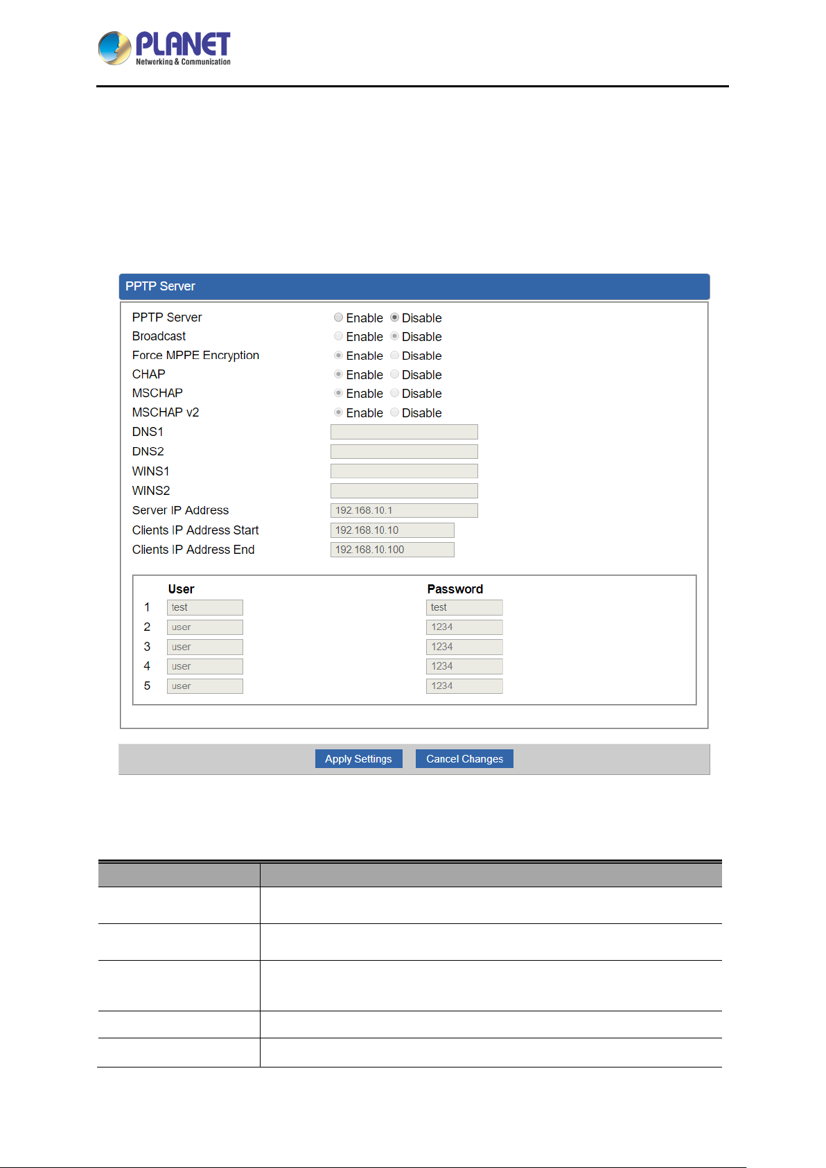
4.7.3 PPTP Server
Use the IP address and the scope option needs to match the far end of the PPTP server; its goal is to
use the PPTP channel technology, and establish Site-to-Site VPN where the channel can have equally
good results from different methods with IPSec. The PPTP server is shown in Figure 4-44.
Object Description
PPTP Server
Broadcast
Force MPPE
Encryption
CHAP
MSCHAP
Figure 4-44: PPTP server
Set the function as enable or disable.
Enter any words for recognition.
Set the encryption as enable or disable.
Set the authentication as enable or disable.
Set the authentication as enable or disable.
- 76 -
Page 77

Industrial 5-Port 10/100/1000T VPN Security Gateway
IVR-100
MSCHAP v2
DNS
WINS
Server IP Address
Clients IP Address
(Start/End)
User and Password
Set the authentication as enable or disable.
When the PPTP client connects to the PPTP server, it will assign the
DNS server IP address to client.
When the PPTP client connects to the PPTP server, it will assign the
WINS server IP address to client.
Input the IP address of the PPTP Server. For instance, "192.168.10.1”.
When the VPN connection is established, the VPN client will get IP
address from the VPN Server. Please set the range of IP Address. For
instance, the start IP address is "192.168.10.10”, the end IP address is
"192.168.10.100”.
Create the username and password for the VPN client.
[Example] Establishing the PPTP VPN connection between two VPN Gateways.
Follow the steps below for setting up the PPTP VPN server:
1. Go to the VPN -> PPTP page of PPTP VPN server.
- 77 -
Page 78

Industrial 5-Port 10/100/1000T VPN Security Gateway
IVR-100
2. Set the PPTP Server as enable.
3. Input the Server IP Address as the Gateway’s another subnet address.
4. Input Clients IP Address Start and Clients IP Address End.
5. Create an account. Enter Username and Password.
6. Click Apply Settings button to save changes.
Follow the following steps for setting up PPTP VPN client:
1. Go to the Network -> WAN page.
- 78 -
Page 79

Industrial 5-Port 10/100/1000T VPN Security Gateway
IVR-100
2. Select Connection Type as PPTP.
3. Input the Server as the VPN Server Gateway’s public WAN IP address.
4. Input the same Username and Password as the one set on the VPN Server Gateway.
5. Go to the System -> Status page to check the Connection Type and IP Address. Make
sure the VPN client Gateway gets the VPN Server’s subnet IP address.
- 79 -
Page 80

Industrial 5-Port 10/100/1000T VPN Security Gateway
Object
Description
4.7.4 L2TP Server
This section assists you in setting the L2TP Server as shown in Figure 4-45.
IVR-100
L2TP Server
Server IP Address
Clients IP Address
(Start/End)
With IPsec
Figure 4-45: L2TP Server
Set the function as enable or disable.
Input the IP address of the L2TP Server. For instance, "192.168.50.1”.
When the VPN connection is established, the VPN client will get IP
address from the VPN Server. Please set the range of IP Address. For
instance, the start IP address is "192.168.50.100”, the end IP address is
"192.168.50.200”.
Set the function as enable to make the L2TP work with IPsec encryption.
- 80 -
Page 81

Industrial 5-Port 10/100/1000T VPN Security Gateway
Object
Description
IVR-100
Preshare Key
User and Password
Connection Type
ISAKMP
Enter a pass phrase.
Create the username and password for the VPN client.
1. Main.
2. Aggressive.
It provides the way to create the SA between two PCs. The SA can
access the encoding between two PCs, and the IT administrator can
assign to which ke y size or Preshare Key and algorith m to use. The SA
comes in many connection ways.
1. AES: All using a 128-bit, 192-bit and 256-bit key. AES is a
commonly seen and adopted nowadays.
2. 3DES: Triple DES is a block cipher formed from the DES cipher by
using it three times. It can achieve an algorithm up to 168 bits.
3. SHA1: The SHA1 is a revision of SHA. It has improved the
shortcomings of SHA. By producing summary hash values, it can
achieve an algorithm up to 160 bits.
4. SHA2: Either 256, 384 or 512 can be chosen.
IKE SA Lifetime
ESP
ESP Key life
5. MD5 Algorithm: MD5 processes a variably long message into a
fixed-length output of 128 bits.
6. DH Group: Either 1, 2, 5, 14, 15, 16, 17, or 18 can be chosen.
You can specify how long IKE packets are valid.
It offers AES, 3 DES, SHA 1, SHA2, and MD5.
1. AES: All using a 128-bit, 192-bit and 256-bit key. AES is a
commonly seen and adopted nowadays.
2. 3DES: Triple DES is a block cipher formed from the DES cipher by
using it three times. It can achieve an algorithm up to 168 bits.
3. SHA1: The SHA1 is a revision of SHA. It has improved the
shortcomings of SHA. By producing summary hash values, it can
achieve an algorithm up to 160 bits.
4. SHA2: Either 256, 384 or 512 can be chosen.
5. MD5 Algorithm: MD5 processes a variably long message into a
fixed-length output of 128 bits.
You can specify how long ESP packets are valid.
[Example] Establishing the L2TP VPN connection between the VPN Gateway and mobile phone.
- 81 -
Page 82
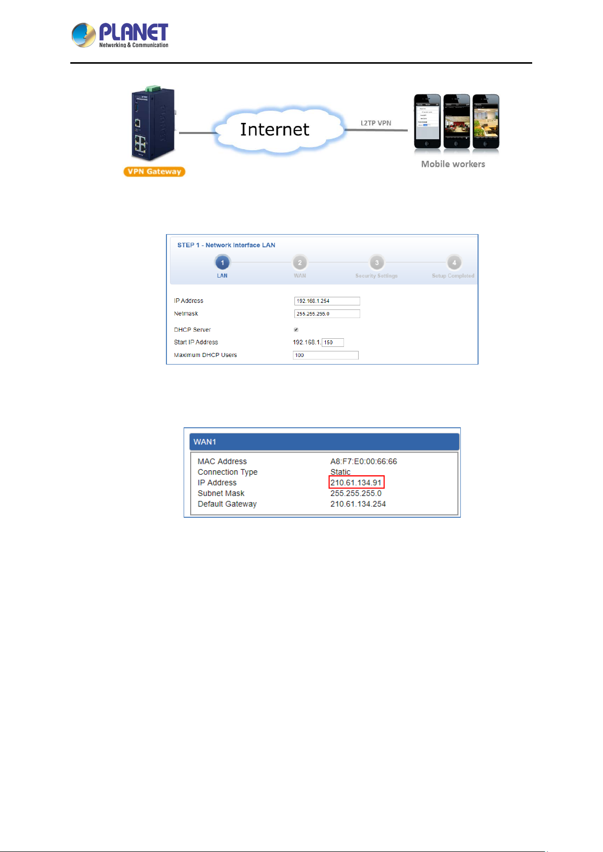
Industrial 5-Port 10/100/1000T VPN Security Gateway
Please refer the steps to configure the VPN settings of the VPN Gateway:
1. Connect the VPN Gateway to internet by the Wizard.
IVR-100
2. Go to the System -> Status page to check the WAN IP address. Make sure the VPN
Gateway gets public IP address successfully.
3. Go to the VPN -> L2TP page. Set the L2TP Server as enable, input the Server IP Address as
the VPN Gateway’ s public WAN IP address and other necessary information.
- 82 -
Page 83

Industrial 5-Port 10/100/1000T VPN Security Gateway
IVR-100
The VPN settings of VPN Gateway are done.
4. Please configure the VPN settings of your mobile phone.
Here we use iPhone as the example: please go to the Settings -> VPN page, click the “Add
VPN Configuration…”.
Note that the VPN settings might be different from each OS of mobile phone, if you do not
know how to configure it, please contact with the dealer of mobile phone.
5. Input the necessary information.
- 83 -
Page 84
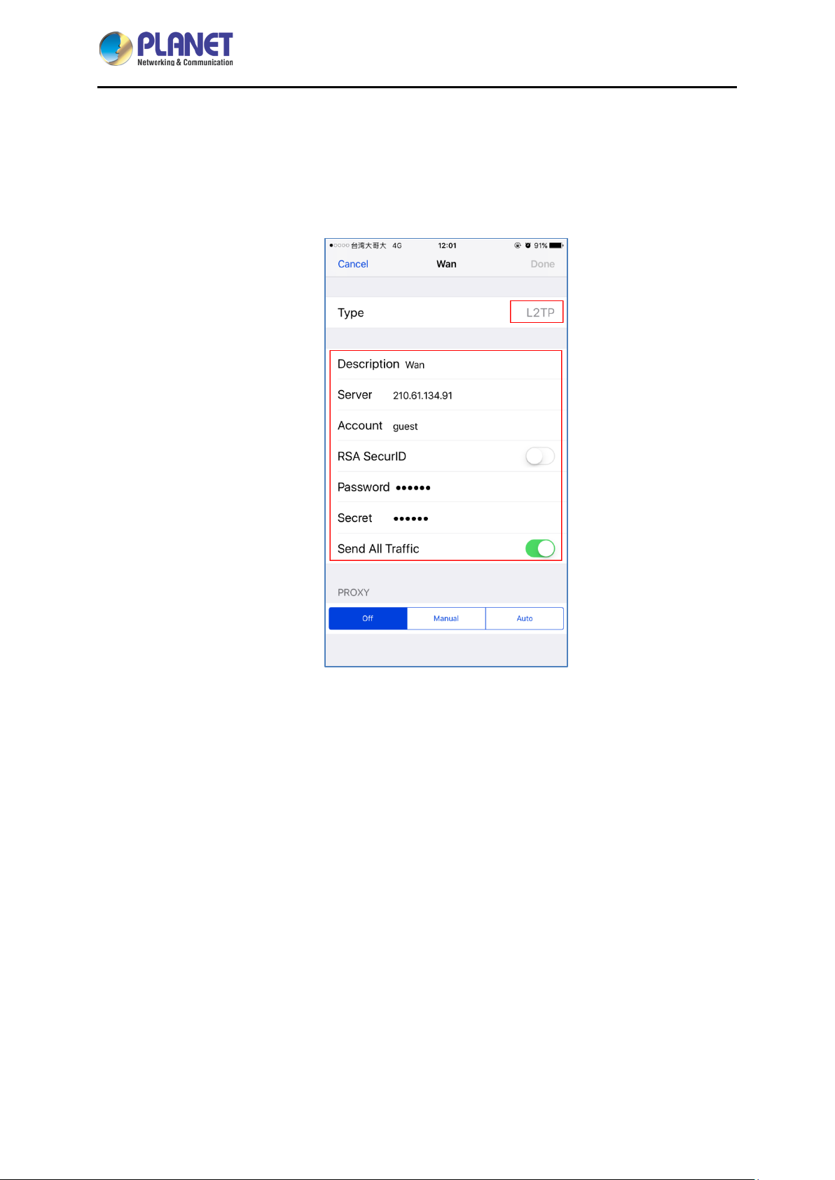
Industrial 5-Port 10/100/1000T VPN Security Gateway
IVR-100
The all information should be the same as VPN Gateway.
For example, the Type should be L2TP, the Server should be the WAN IP of VPN Gateway,
the account should be the L2TP User of VPN Gateway, the Password should be the L2TP
Password of VPN Gateway, and the Secret should be the L2TP Preshare Key of VPN
Gateway.
6. Slide the Status slider to “Connecting”, it will start to connect to the VPN server. When the
VPN connection is established, the Status will show “Connected”.
- 84 -
Page 85

Industrial 5-Port 10/100/1000T VPN Security Gateway
IVR-100
4.7.5 SSL VPN
This section assists you in setting the SSL Server as shown in Figure 4-46.
Object Description
SSL VPN Server
Figure 4-46: SSL Server
Set the function as enable or disable.
- 85 -
Page 86

Industrial 5-Port 10/100/1000T VPN Security Gateway
IVR-100
Port
Tunnel Protocol
Virtual Network
Device
Interface
VPN Network
Network Mask
Encryption Cipher
Hash Algorithm
Export client.ovpn
Set a port for the SSL Service. Default port is 1194.
Set the protocol as TCP or UDP.
Set the Virtual Network Device as TUN or TAP.
User is able to select the interface for SSL service using.
The VPN subnet in CIDR notation. For instance, "192.168.20.0”.
The netmask of the VPN.
There are four encryption types: Non e, A E S-128 CBC, AES-192 CBC or
AES-256 CBC.
There are five types of Hash Algorit hm : None, SHA1, SHA1 , SHA5 12 or
MD5.
Export a configuration for the SSL client. User is able to upload it to VPN
client (such as Open VPN software).
4.7.6 VPN Connection
This page shows the VPN connection status as shown in Figure 4-47.
Figure 4-47: VPN Connection Status
Object Description
VPN Connection
Status
Click the IPSec/GRE/ …/SSL VPN bookmark to chec k the current
connection status.
- 86 -
Page 87

Industrial 5-Port 10/100/1000T VPN Security Gateway
Object
Description
IVR-100
4.8 Maintenance
The Maintenance menu provides the following features for managing the system as Figure 4-48 is
shown below:
Administrator
Date & Time
Save/Restore
Configuration
Firmware Upgrade
Reboot / Reset
Auto Reboot
Diagnostics
Figure 4-48: Maintenance Menu
Allows changing the login username and password.
Allows setting Date & Time function.
Export the Gateway’s configuration to local or USB sticker.
Restore the Gateway’s configuration from local or USB sticker.
Upgrade the firmware from local or USB storage.
Reboot or reset the system.
Allows setting auto-reboot schedule.
Allows you to issue ICMP PING packets to troubleshoot IP.
4.8.1 Administrator
To ensure the Gateway's security is secure, you will be asked for your password when you access the
Gateway's Web-based utility. The default user name and password are "admin". This page will allow
you to modify the user name and passwords as shown in Figure 4-21.
- 87 -
Page 88

Industrial 5-Port 10/100/1000T VPN Security Gateway
IVR-100
Figure 4-48: Administrator
Object Description
Username
Password
Confirm Password
Input a new username.
Input a new password.
Input password again.
4.8.2 Date and Time
This section assists you in setting the system time of the Gateway. You are able to either select to set
the time and date manually or automatically obtain the GMT time from Internet as shown in Figure 4-49.
Object Description
Current Time
Time Zone Select
Figure 4-49: Date and Time
Show the current time.
User is able to set time and date manually.
Select the time zone of the country you are currently in. The Gateway will
set its time based on your selection.
- 88 -
Page 89

Industrial 5-Port 10/100/1000T VPN Security Gateway
Object
Description
IVR-100
NTP Client Update
NTP Server
Once this function is enab led, Gateway will autom aticall y update c urrent
time from NTP server.
User may use the default NTP sever or input NTP server manually.
4.8.3 Saving/Restoring Configuration
This page shows the status of the configuration. You may save the setting file to either USB storage or
PC and load the setting file from USB storage or PC as Figure 4-50 is shown below:
Figure 4-50: Save/Restore Configuration
■ Save Setting to PC
Configuration Export
Press the button to save setting file to PC.
Press the button to select the setting file, and then
Configuration Import
press the button to upload setting file from PC.
■ Save Setting to USB Storage
Object Description
USB Storage
The status of USB storage.
- 89 -
Page 90

Industrial 5-Port 10/100/1000T VPN Security Gateway
Object
Description
Object
Backup Settings to
USB Storage
Load Settings from
USB Storage
Unmount
Press the button to save setting file to USB storage.
Press the
Before removing the USB storage fr om the Gateway, please press the
button first.
button to upload setting file from USB storage.
4.8.4 Upgrading Firmware
This page provides the firmware upgrade of the Gateway as shown in Figure 4-51.
IVR-100
Figure 4-51: Firmware upgrade
Description
Choose File
Upgrade
Press the button to select the firmware.
Press the button to upgrade firmware to system.
4.8.5 Reboot / Reset
This page enables the device to be rebooted from a remote location. Once the Reboot button is
pressed, users have to re-log in the Web interface as Figure 4-52 is shown below:
- 90 -
Page 91

Industrial 5-Port 10/100/1000T VPN Security Gateway
Object
IVR-100
Figure 4-52: Reboot/Reset
Description
Reboot
Reset
I'd like to keep the network
profiles.
Press the button to r eb oot system.
Press the button to restore all settings to factory default
settings.
Check the box and then press the button
to keep the current network profiles and reset all other
configurations to factory defaults.
4.8.6 Diagnostics
The page allows you to issue ICMP PING packets to troubleshoot IP connectivity issues. After you have
pressed “Ping”, ICM P packets will be transmitted, and the sequence number and roundtrip time will be
displayed upon reception of a reply. The Page refreshes automatically until responses to all packets are
received, or until a timeout occurs. The ICMP Ping is shown in Figure 4-53.
Figure 4-53: Ping
- 91 -
Page 92

Industrial 5-Port 10/100/1000T VPN Security Gateway
Object
Description
,
IVR-100
Interface
Target Host
Number of Packets
Ping
Be sure the target IP address is within the same network subnet of the Gateway
or you have to set up the correct gateway IP address.
Select an interface of the Gateway.
The destination IP Address or domain.
Set the number of packets that will be transmitted; the
maximum is 100.
The time of ping.
- 92 -
Page 93

Industrial 5-Port 10/100/1000T VPN Security Gateway
IVR-100
Appendix A: DDNS Application
Configuring PLANET DDNS steps:
Step 1: Visit DDNS provider’s web site and register an account if you do not have one yet. For example,
register an account at http://planetddns.com
Step 2: Enable DDNS option through accessing web page of the device.
Step 3: Input all DDNS settings.
- 93 -
 Loading...