

Page 1

User's Manual
ISW-504PS / ISW-514PS
ISW-514PS15 / ISW-514PSF
5-Port 10/100Mbps with
4-Port PoE Web Smart
Industrial Ethernet Switch
-1-
Page 2

Trademarks
Copyright © PLANET Technology Corp. 2010.
Contents subject to revise without prior notice.
PLANET is a registered trademark of PLANET Technology Corp. All other trademarks belong to their respective
owners.
Disclaimer
PLANET Technology does not warrant that the hardware will work properly in all environments and applications,
and makes no warranty and representation, either implied or expressed, with respect to the quality, performance,
merchantability, or fitness for a particular purpose.
PLANET has made every effort to ensure that this User’s Manual is accurate; PLANET disclaims liability for any
inaccuracies or omissions that may have occurred.
Information in this User’s Manual is subject to change without notice and does not represent a commitment on the
part of PLANET. PLANET assumes no responsibility for any inaccuracies that may be contained in this User’s
Manual. PLANET makes no commitment to update or keep current the information in this User’s Manual, and
reserves the right to make improvements to this User’s Manual and/or to the products described in this User’s
Manual, at any time without notice.
User’s Manual
If you find information in this manual that is incorrect, misleading, or incomplete, we would appreciate your
comments and suggestions.
FCC Warning
This equipment has been tested and found to comply with the limits for a Class A digital device, pursuant to Part 15
of the FCC Rules. These limits are designed to provide reasonable protection against harmful interference when
the equipment is operated in a commercial environment. This equipment generates, uses, and can radiate radio
frequency energy and, if not installed and used in accordance with the Instruction manual, may cause harmful
interference to radio communications. Operation of this equipment in a residential area is likely to cause harmful
interference in which case the user will be required to correct the interference at his own expense.
CE Mark Warning
This is a Class A product. In a domestic environment, this product may cause radio interference, in which case the
user may be required to take adequate measures.
Energy Saving Note of the Device
This power required device does not support Standby mode operation.
For energy saving, please remove the power cable to disconnect the device from the power circuit.
Without removing power cable, the device will still consuming power from the power source. In the view of Saving the
Energy and reduce the unnecessary power consuming, it is strongly suggested to remove the power connection for the
device if this device is not intended to be active.
-2 -
Page 3

WEEE Warning
To avoid the potential effects on the environment and human health as a result of the presence of
hazardous substances in electrical and electronic equipment, end users of electrical and electronic
equipment should understand the meaning of the crossed-out wheeled bin symbol. Do not dispose of
WEEE as unsorted municipal waste and have to collect such WEEE separately.
Revision
PLANET 5-Port 10/100Mbps with 4-Port PoE Web Smart Industrial Ethernet Switch User's Manual
FOR MODELS: ISW-504PS / ISW-514PS / ISW-514PS15 / ISW-514PSF
REVISION: 1.0 (JULY.2010)
Part No.: EM-ISW-5xxPS Series_v1.0 (2080-AH0240-000)
User’s Manual
-3 -
Page 4

User’s Manual
TABLE OF CONTENTS
1. INTRODUCTION ............................................................................................................7
1.1 PACKAGE CONTENTS................................................................................................................................. 7
1.2 PRODUCT DESCRIPTION .............................................................................................................................7
1.3 FEATURES.................................................................................................................................................8
1.4 SPECIFICATION ..........................................................................................................................................9
1.5 PRODUCT APPLICATION ........................................................................................................................... 11
2. INSTALLATION............................................................................................................12
2.1 HARDWARE DESCRIPTION ........................................................................................................................12
2.1.1 Physical Dimension......................................................................................................................... 12
2.1.2 Front Panel ..................................................................................................................................... 12
2.1.2 Front Panel ..................................................................................................................................... 13
2.1.3 LED Indicators ................................................................................................................................14
2.1.4 Switch Upper Panel ........................................................................................................................15
2.2 INSTALL THE SWITCH................................................................................................................................16
2.2.1 Installation Steps............................................................................................................................. 16
2.2.2 DIN-Rail Mounting........................................................................................................................... 16
2.2.3 Wall Mount Plate Mounting............................................................................................................. 19
2.3 WIRING THE POWER INPUTS .....................................................................................................................19
2.4 WIRING THE FAULT ALARM CONTACT....................................................................................................... 20
2.5 CABLING .................................................................................................................................................21
2.5.1 Installing the SFP transceiver (ISW-514PSF Only) ........................................................................ 21
2.5.2 Remove the module........................................................................................................................ 23
3 MANAGEMENT.............................................................................................................24
3.1 OVERVIEW............................................................................................................................................... 24
3.2 REQUIREMENTS .......................................................................................................................................24
3.3 MANAGEMENT METHOD ........................................................................................................................... 24
3.3.1 Web Management........................................................................................................................... 24
3.3.2 PLANET Smart Discovery Utility..................................................................................................... 27
4. WEB CONFIGURATION ..............................................................................................29
4.1 MAIN MENU ............................................................................................................................................. 29
4.2 WEB PANEL.............................................................................................................................................30
4.3 SYSTEM................................................................................................................................................... 31
-4 -
Page 5

User’s Manual
4.3.1 System Information ......................................................................................................................... 32
4.3.2 IP Configuration .............................................................................................................................. 33
4.3.3 Password Setting ............................................................................................................................ 34
4.3.4 Firmware Upgrade .......................................................................................................................... 34
4.3.5 Configuration Setting ...................................................................................................................... 38
4.3.6 Configuration Backup...................................................................................................................... 40
4.3.7 Managed IP..................................................................................................................................... 41
4.3.8 Fault Relay Alarm ........................................................................................................................... 41
4.3.9 Alert Trap Configuration.................................................................................................................. 42
4.3.10 System Reboot ............................................................................................................................. 43
4.4 PORT MANAGEMENT ................................................................................................................................44
4.4.1 Port Configuration ........................................................................................................................... 44
4.4.2 Port Status ...................................................................................................................................... 45
4.4.3 Port Security ................................................................................................................................... 46
4.5 VLAN .....................................................................................................................................................47
4.5.1 VLAN Group.................................................................................................................................... 50
4.5.2 VLAN Per Port Setting .................................................................................................................... 54
4.5.3 VLAN setting example: ...................................................................................................................56
4.6 QUALITY OF SERVICE...............................................................................................................................63
4.6.1 802.1p Tag Priority Mode................................................................................................................ 64
4.6.2 DSCP QoS Mode............................................................................................................................ 66
4.6.3 Port-Based Priority Mode................................................................................................................ 69
4.7 STORM CONTROL.....................................................................................................................................70
4.8 MISC CONFIGURATION ............................................................................................................................. 71
4.9 POE CONFIGURATION .............................................................................................................................. 73
4.9.1 Power over Ethernet Powered Device............................................................................................ 73
4.9.2 Power Management:....................................................................................................................... 73
4.10 LOGOUT ................................................................................................................................................76
5. SWITCH OPERATION..................................................................................................77
5.1 ADDRESS TABLE......................................................................................................................................77
5.2 LEARNING................................................................................................................................................77
5.3 FORWARDING & FILTERING ...................................................................................................................... 77
5.4 STORE-AND-FORWARD ............................................................................................................................ 77
5.5 AUTO-NEGOTIATION.................................................................................................................................78
-5 -
Page 6

User’s Manual
6. POWER OVER ETHERNET OVERVIEW.....................................................................79
7. THE POE PROVISION PROCESS...............................................................................82
7.1 LINE DETECTION......................................................................................................................................82
7.2 CLASSIFICATION ...................................................................................................................................... 82
7.3 START-UP................................................................................................................................................83
7.4 OPERATION .............................................................................................................................................83
7.5 POWER DISCONNECTION SCENARIOS........................................................................................................ 83
8. TROUBLESHOOTING..................................................................................................85
APPENDIX A NETWORKING CONNECTION .................................................................86
A.1 DATA OUT POE SWITCH RJ-45 PORT PIN ASSIGNMENTS (PORT 1 TO PORT-4)....................................... 86
A.2 10/100MBPS, 10/100BASE-TX ............................................................................................................... 86
APPENDIX B....................................................................................................................88
B.1 POWER OVER ETHERNET COMPATIBILITY TEST ......................................................................................... 88
B.2 COMPATIBLE 100BASE-FX SFP TRANSCEIVER LIST (ISW-514PSF)........................................................88
-6 -
Page 7

User’s Manual
1. INTRODUCTION
The PLANET Layer 2 Web Smart Industrial PoE Switch series – ISW-5xxPS is multiple 10/100Mbps ports Ethernet
Switched with 4-Port 802.3af PoE inject ability and robust layer 2 features; the description of these models as below:
ISW-504PS :
ISW-514PS :
ISW-514PS15 :
ISW-514PSF :
5-Port 10/100Mbps with 4-PoE Industrial Web Smart Switch (-10~60 Degree C)
4+1 100FX Port (SC) with 4-PoE Industrial Web Smart Switch - 2km (-10~60 Degree C)
4+1 100FX Port (SC) with 4-PoE Industrial Web Smart Switch - 15km (-10~60 Degree C)
4+1 100FX Port (LC) with 4-PoE Industrial Web Smart Switch (-10~60 Degree C)
1.1 Package Contents
Check the contents of your package for following parts:
Managed PoE Switch x1
User's Manual CD x1
Quick Installation Guide x1
DIN Rail Kit x 1
Wall Mount Kit x 1
If any of these pieces are missing or damaged, please contact your dealer immediately, if possible, retain the carton
including the original packing material, and use them against to repack the product in case there is a need to return it to us
for repair.
1.2 Product Description
The ISW-504PS / ISW-514PS series support MDI/ MDI-X convertible on 5 / 4-10/100Mbps ports, also provide PoE inject
function on port 1, 2, 3 and 4, which is able to drive 4 IEEE 802.3af compliant powered devices. The dual speed ports use
standard twisted-pair cabling and are ideal for SOHO or segmenting networks into small. Each 10/100Mbps port can
supports up to 200Mbps of throughput in full-duplex mode, ISW-504PS / ISW-514PS series also provides a simple,
cost-effective, and highly reliable network connection for data transmits. Furthermore, it is the ideal device for bridging
among Ethernet, Fast Ethernet workgroups and networks.
With 4 PoE interfaces, the ISW-504PS / ISW-514PS series is ideal for small business and workgroups requiring to deploy
the PoE for the wireless access points, IP-based surveillance camera or IP phones in any places easily, efficiently and cost
effective.
The front panel of ISW-504PS / ISW-514PS series provides LEDs for easy recognition of the switch operation status and
troubleshooting. These LED indicators display the power status for the system, LNK/ACT and speed for each10/100M
port. Also the PoE in use LED indicates for PoE ports (port 1 to port 4).
With data and power over Ethernet from one unit, the ISW-504PS / ISW-514PS series shall reduce cables and eliminates
the need for dedicated electrical outlets on the wall, ceiling or any unreachable place. A wire carries both data and power
lowering the installation costs, simplifying the installation effort and eliminating the need for electricians or extension cords.
-7 -
Page 8
User’s Manual
The smart functions make it easy to survey and control the PoE power provision to the devices by the Web interface. Basic
switching functions such as VLAN, bandwidth control and QoS are available for network management.
With Fast Ethernet SFP interface, the ISW-514PSF is with high reliability and flexibility to extend the distance from 2km to
20Km. It depends on the MFB family Fast Ethernet SFP modules.
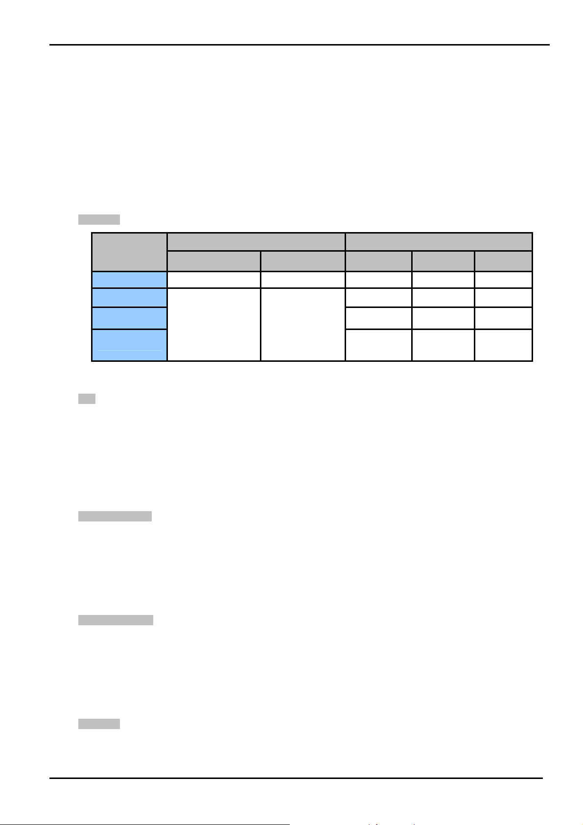
1.3 Features
¾ Interfaces
Model Name
Copper Optical Mode Connector Distance
ISW-504PS
ISW-514PS
ISW-514PS15
ISW-514PSF
4-Port support 48V DC power to PoE Powered Device
¾ PoE
Comply with IEEE 802.3af Power over Ethernet End-Span PSE
Up to 4 IEEE 802.3af devices powered
Support PoE Power up to 15.4 Watts for each PoE ports
Auto detect powered device (PD)
Circuit protection prevent power interference between ports
Remote power feeding up to 100m
¾ PoE Management
5 x 10/100Base-TX NA NA NA NA
4 x 10/100Base-TX 1 x 100Base-FX
Ports Fiber Optical Interface
Multi-Mode SC 2km
Single-Mode SC 15km
Optional SFP
Module
LC
Depend on
SFP
Module
Total PoE power budget control
Enable / Disable PoE function on each port
PoE port Power feeding priority
Power limit on PoE port
PD classification detection
¾ Web Management
Web interface for remote management
Firmware upgrade through Web interface
SNMP Trap for alarm notification of events
VLAN and QoS configuration
PLANET Smart Discovery utility automatically finds PLANTE devices on the network
¾ Switching
Complies with IEEE 802.3 10Base-T, IEEE 802.3u 100Base-TX / 100Base-FX Ethernet standard
Supports Auto-Negotiation and 10/100Mbps Half / Full Duplex and Auto MDI / MDI-X
-8 -
Page 9
High performance Store and Forward architecture, Storm Control and runt/CRC filtering eliminates erroneous
packets to optimize the network bandwidth
Prevents packet loss with back pressure (Half-Duplex) and IEEE 802.3x PAUSE Frame flow control
(Full-Duplex)
Backplane (Switching Fabric): 1Gbps
Automatic address learning and address aging
Integrated address look-up engine, support 1K absolute MAC addresses
CSMA/CD Protocol
¾ Industrial Case / Installation
IP-30 Aluminum case / Protection
DIN Rail and Wall Mount Design
24 or 48V DC, redundant power with polarity reverse protect function
Supports EFT protection 6000V DC for power line
Supports 6000V DC Ethernet ESD protection
-10 to 60 Degree C operation temperature
User’s Manual
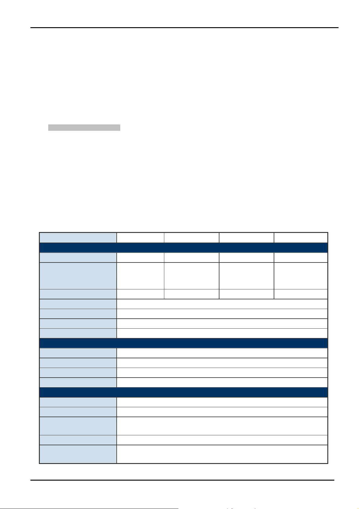
1.4 Specification
Model ISW-504PS ISW-514PS ISW-514PS15 ISW-514PSF
Hardware Specification
10/100Base-TX Ports 5 4 4 4
1
100Base-FX Interface N/A
IEEE 802.3af PoE Ports 4 4 4 4
Dimensions (D x W x H) 135mm x 87.8mm x 56mm
Weight 871g
Power Requirement 24 or 48V DC
Installation DIN Rail Kit and Wall Mount Ear
(SC-Multi Mode,
2km)
(SC-Single Mode,
Power Over Ethernet
PoE Standard IEEE 802.3af Power over Ethernet / PSE
PoE Power Supply Type End-Span
PoE Power Output 48V DC Per Port, 350mA . Max. 15.4 Watts
Power Pin Assignment 1/2(+), 3/6(-)
Switch Specification
Switch Processing Scheme Store-and-Forward
Address Table 1K entries
Flow Control
Switch Fabric 1Gbps
Throughput
(Packet Per Second)
Back Pressure for Half Duplex
IEEE 802.3x Pause Frame for Full Duplex
0.74Mpps
1
15km)
1
(LC-Opitional SFP
module )
-9 -
Page 10

10/100Base-TX:
Cat. 3, 4, 5, 5e, 6 UTP cable (100meters max.)
EIA/TIA-568 100-ohm STP (100meters max.)
Network Cables
Multi-mode optic fiber
NA
62.5/125μm,
50/125μm (2km max.).
Layer 2 Function
Management Web management, SNMP Trap
• Port-Based VLAN
VLAN
QoS
• IEEE 802.1Q Tag-Based VLAN
Up to 16 VLAN groups
2 priority queues for three type of Class of Service
• Port-Based
• IEEE 802.1p priority tag
• TCP/IP header’s DSCP classifier
Weighted Round Robin queue scheduling
Single-mode optic
fiber 9/125μm (15km
max.).
User’s Manual
Multi-mode optic
fiber 62.5/125μm,
50/125μm
Single-mode optic
fiber 9/125μm
(Vary on SFP
Module)
Bandwidth Control Inbound Rate Limit and Outbound Traffic shaping
Storm Control Disable, 12.5%, 25%, 50%, 62.5% 4 levels
Standards Conformance
IEEE 802.3 Ethernet
IEEE 802.3u Fast Ethernet
Standards Compliance
Temperature
Humidity Operating: 5~90%, Storage: 5~90% (Non-condensing)
Regulation Compliance FCC Part 15 Class A, CE
Stability Testing
IEEE 802.3x Full-Duplex Flow Control
IEEE 802.3af Power over Ethernet
IEEE 802.1Q VLAN
IEEE 802.1p Class of Service
Operating: -10 to 60℃
Storage: -40 to 70℃
IEC60068-2-32(Free Fall)
IEC60068-2-27(Shock)
IEC60068-2-6(Vibration)
-10 -
Page 11
User’s Manual
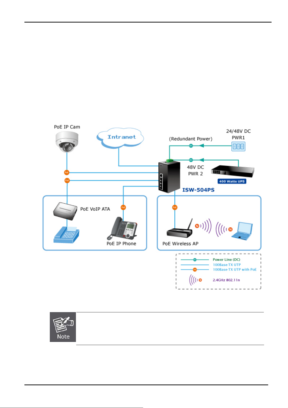
1.5 Product Application
As a department / workgroup PoE Switch
Providing up to 4 PoE, in-line power interface, the Industrial PoE Switch can easily build a power central-controlled IP
phone system, IP Camera system, AP group for the enterprise. For instance, 4 camera / AP can be easily installed around
the corner in the company for surveillance demands or build a wireless roaming environment in the office. Without the
power-socket limitation, the Industrial PoE Switch makes the installation of cameras or WLAN AP more easily and
efficiently.
Figure 1-1 PoE Switch connection
Cable distance for Switch
1. The UTP/STP cable distances between PCs should not exceed 100 meters.
2. The Fiber Optic cable distances between PCs should not exceed maximum distance support
by each model.
-11 -
Page 12
User’s Manual
2. INSTALLATION
2.1 Hardware Description
The ISW-504PS / ISW-514PS series provide two different running speeds – 10Mbps, 100Mbps in the same Switch and
automatically distinguish the speed of incoming connection.
This section describes the hardware features of ISW-504PS / ISW-514PS series. For easier management and control of
the Switch, familiarize yourself with its display indicators, and ports. Front panel illustrations in this chapter display the unit
LED indicators. Before connecting any network device to the ISW-504PS / ISW-514PS series, read this chapter carefully.
In the following section, the term “Industrial PoE Switch” means the ISW-504PS / ISW-514PS / ISW-514PS15 /
ISW-514PSF.
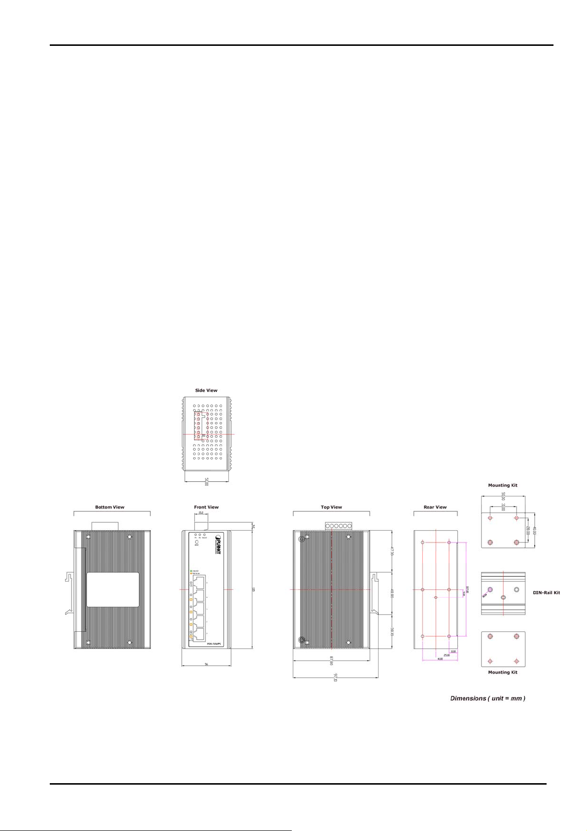
2.1.1 Physical Dimension
ISW-5xxPS series Web Smart Industrial Switch dimension (D x W x H) : 135mm x 87.8mm x 56mm
-12 -
Page 13
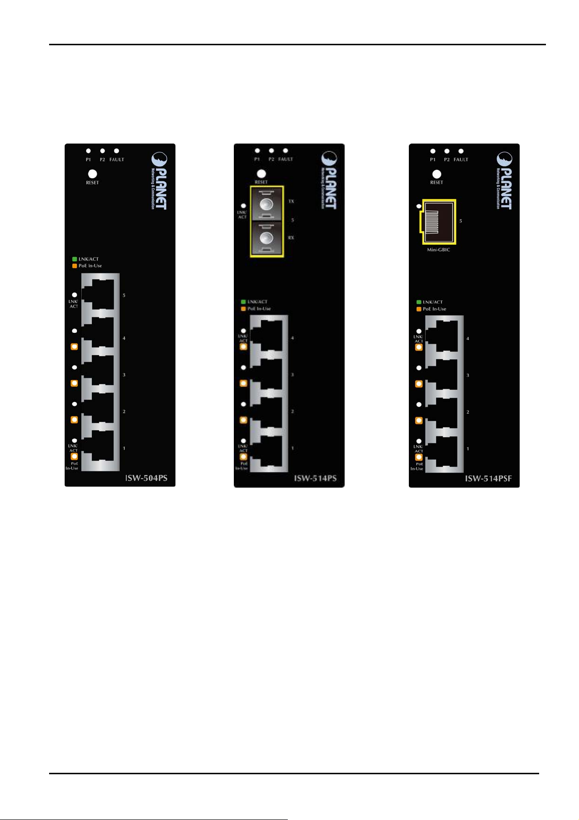
2.1.2 Front Panel
Figure 2-1 shows a front panel of Industrial PoE Switch.
User’s Manual
Figure 2-1 ISW-504PS and ISW-514PS / ISW-514PS15 and ISW-514PF Switch front panel
■ Reset Button
At the left of front panel, the reset button is designed for reboot the Industrial PoE Switch without turn off and on the
power, also can reset the Industrial PoE Switch to factory default mode.
-13 -
Page 14
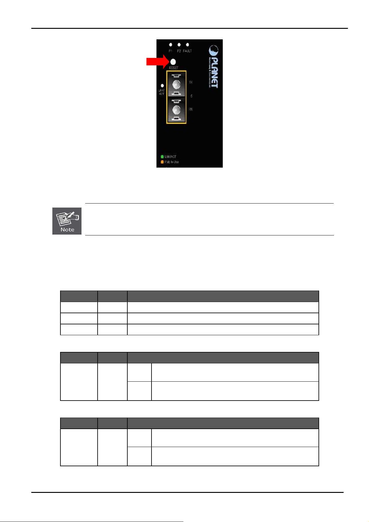
User’s Manual
Figure 2-2 Reset button of Industrial PoE Switch
1. Press the RESET button once. The Industrial PoE Switch will reboot automatically.
2. Press the RESET button for 5 seconds. The Industrial PoE Switch will back to the factory
default mode; the entire configuration will be erased.
2.1.3 LED Indicators
System
LED Color Function
P1 Green Indicate the power 1 has power.
P2 Green Indicate the power 2 has power.
Fault Green Indicate the either power 1 or power 2 has no power.
Per 10/100Base-TX Port
LED Color Function
LNK / ACT Green
Light
Blink
Indicate the link through that port is successfully
established at 10 or 100Mbps.
Indicate that the Switch is actively sending or receiving
data over that port.
Per 100Base-FX Port
LED Color Function
LNK/ ACT Green
Light
Blink
Indicate the link through that port is successfully established
at 10 or 100Mbps.
Indicate that the Switch is actively sending or receiving data
over that port.
-14 -
Page 15
User’s Manual
PoE Port
LED Color Function
PoE In Use Orange Indicate the port is providing 48V DC in-line power. (1-4 ports)
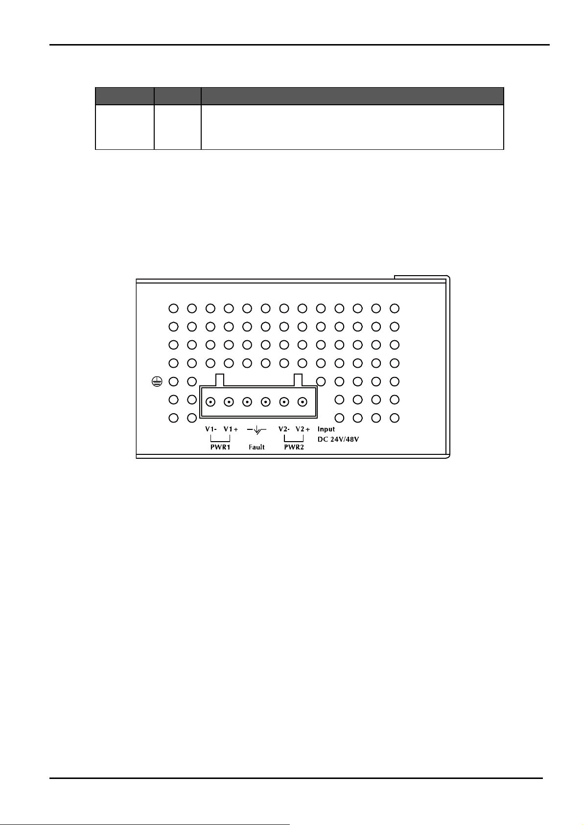
2.1.4 Switch Upper Panel
The Upper Panel of the Industrial PoE Switch indicates a DC inlet power socket and consist one terminal block connector
within 6-contacts. It accepts input power from 24 or 48V DC.
Figure 2-3 Industrial PoE Switch Upper Panel
-15 -
Page 16

User’s Manual
2.2 Install the switch
This section describes how to install your Managed Industrial Switch and make connections to the Managed Industrial
Switch. Please read the following topics and perform the procedures in the order being presented. To install your switch on
a desktop or shelf, simply complete the following steps.
In this paragraph, we will describe how to install the Industrial Switch and the installation points attended to it.
2.2.1 Installation Steps
1. Unpack the Indu strial switch
2. Check if the DIN-Rail is screwed on the Industrial switch or not. If the DIN-Rail is not screwed on the Industrial
switch, please refer to DIN-Rail Mounting section for DIN-Rail installation. If users want to wall mount the Industrial
switch, please refer to Wall Mount Plate Mounting section for wall mount plate installation.
3. To hang the Industrial switch on the DIN-Rail track or wall.
4. Power on the Industrial switch. Please refer to the Wiring the Power Inputs section for knowing the information
about how to wire the power. The power LED on the Industrial switch will light up. Please refer to the LED Indicators
section for indication of LED lights.
5. Prepare the twisted-pair, straight through Category 5 cable for Ethernet connection.
6. Insert one side of RJ-45 cable (category 5) into the Industrial s witch Ethernet port (RJ-45 port) and another side
of RJ-45 cable (category 5) to the network device’s Ethernet port (RJ-45 port), ex: Switch PC or Server. The UTP
port (RJ-45) LED on the Industrial switch will light up when the cable is connected with the network device. Please
refer to the LED Indicators section for LED light indication.
Make sure that the connected network devices support MDI/MDI-X. If it does not support, use
the crossover category-5 cable.
7. When all con nections are set and LED lights all show in normal, the installation is complete.
2.2.2 DIN-Rail Mounting
This section describes how to install the Industrial PoE Switch.
There have two methods to install the Industrial PoE Switch. DIN-Rail Mounting and Wall Mount Plate Mounting. Please
read the following topics and perform the procedures in the order being presented.
-16 -
Page 17
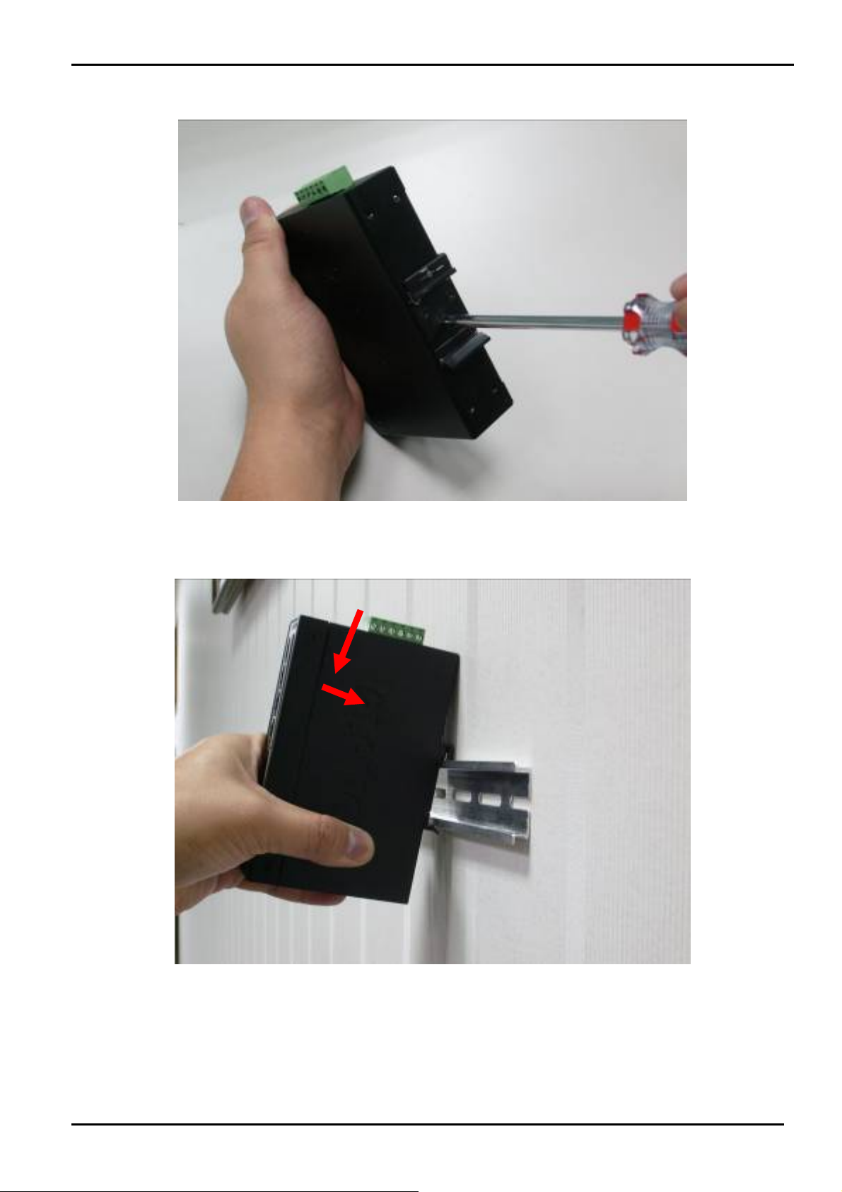
Step 1: Screw the DIN-Rail on the Industrial PoE Switch.
User’s Manual
Step 2: Lightly press the button of DIN-Rail into the track.
-17 -
Page 18
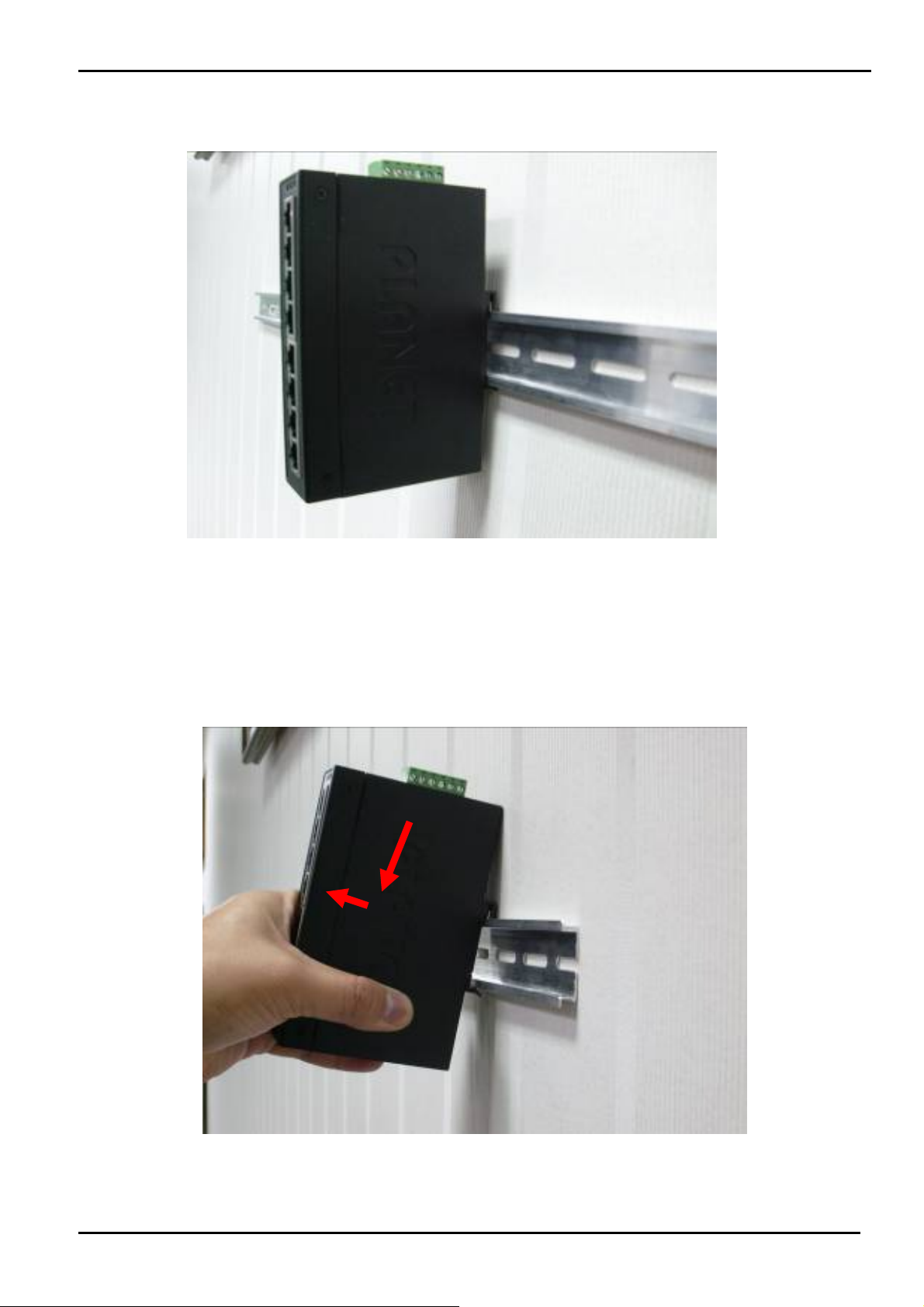
Step 3: Check the DIN-Rail is tightly on the track.
User’s Manual
Please refer to following procedures to remove the Industrial PoE Switch from the track.
Step 5: Lightly press the button of DIN-Rail for remove it from the track.
-18 -
Page 19

User’s Manual
2.2.3 Wall Mount Plate Mounting
To install the Industrial PoE Switch on the wall. Please follow the instructions below.
Step 1: Remove the DIN-Rail from the Industrial PoE Switch. Use the screwdriver to loose the screws and remove the
DIN-Rail.
Step 2: Place the wall mount plate on the rear panel of the Industrial PoE Switch.
Step 3: Use the screwdriver to screw the wall mount plate on the Industrial PoE Switch.
Step 4: Use the hook holes at the corners of the wall mount plate to hang the Industrial PoE Switch on the wall.
Step 5: To remove the wall mount plate, reverse steps above.
2.3 Wiring the Power Inputs
The 6-contacts terminal block connector on the top panel of Industrial PoE Switch is used for two DC redundant power
inputs. Please follow the steps to insert the power wire. The PWR1 is 1(-) & 2(+) and PWR2 is 5(-) & 6(+) contact.
Remember: Tighten the wire-clamp screws for preventing the wires from loosing.
-19 -
Page 20
Power Notice:
User’s Manual
1 2 3 4 5 6
Power 1 Fault Power 2
- + - +
Figure 2-4: 6-Contacts of Terminal Block Connector
1. The wire gauge for the terminal block should be in the range between 12 ~ 24 AWG.
2. Performing any of the procedures like inserting the wires or tighten the wire-clamp screws. Ensure
the power is OFF to prevent to get an electric shock.
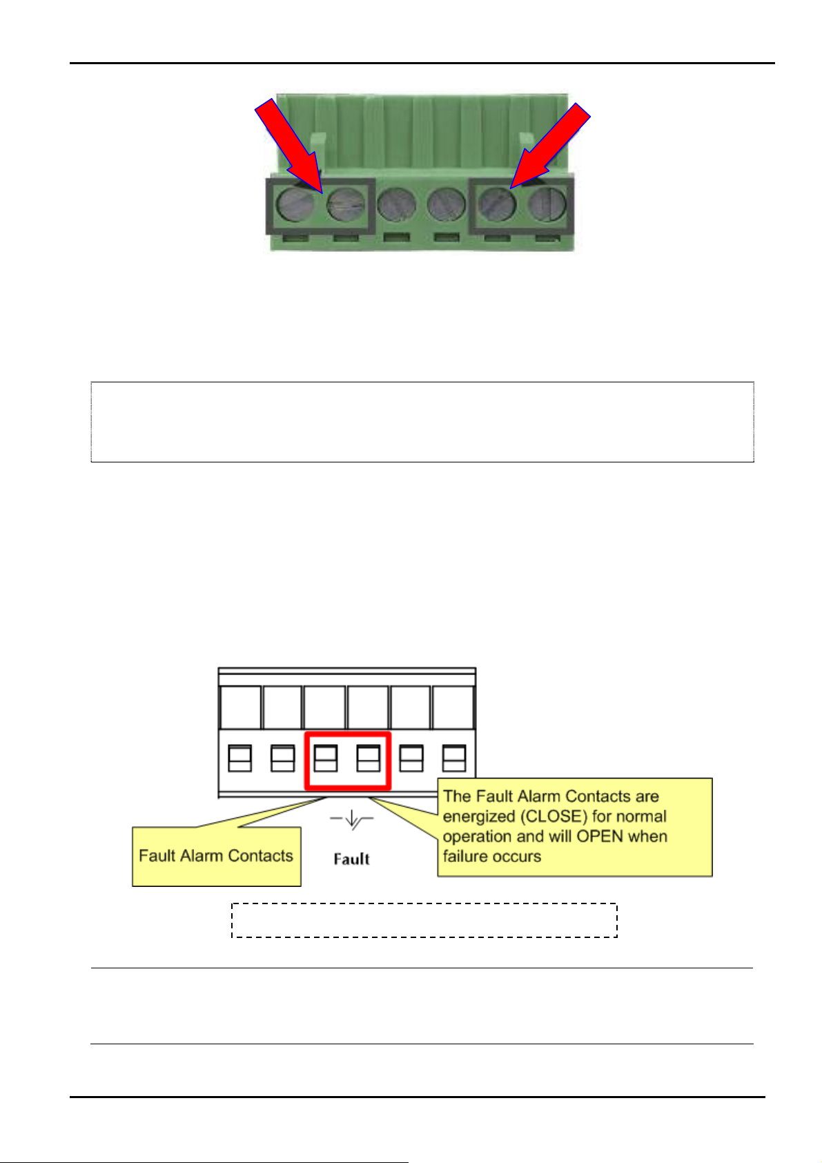
2.4 Wiring the Fault Alarm Contact
The fault alarm contacts are in the middle (3 & 4) of the terminal block connector as the picture shows below. Inserting the
wires, the Industrial PoE Switch will detect the fault status of the power failure, or port link failure (available for managed
model).
The following illustration shows an application example for wiring the fault alarm contacts
Power Notice:
Insert the wires into the fault alarm contacts
1. The wire gauge for the terminal block should be in the range between 12 ~ 24 AWG.
2. Performing any of the procedures like inserting the wires or tighten the wire-clamp screws. Ensure
the power is OFF to prevent to get an electric shock.
-20 -
Page 21

User’s Manual
2.5 Cabling
100Base-TX and 100Base-FX
The 10/100Mbps RJ-45 ports come with Auto-Negotiation capability. Users only need to plug in working network
device into one of the 10/100Mbps RJ-45 ports. The ISW-504PS / ISW-514PS series will automatically run in 10Mbps
or 100Mbps after the negotiation with the connected device. The ISW-514PS has one 100Base-FX SC Interface
(Multi-mode, 50/125μm or 62.5/125μm fiber cable and the available distance is 2km). The ISW-514PS15 has one
100Base-FX SC Interface (Single-mode, 9 / 125μm fiber cable and the available distance is 15km). The ISW-514PSF
has one 100Base-FX SFP interface (Optional Multi-mode / Single-mode 100Base-FX SFP module)
Cabling
Each 10/100Base-TX ports use RJ-45 sockets -- for connection of unshielded twisted-pair cable (UTP).
The 100Base-FX port is uses as SC / LC connector. Please see table below and know more about the cable’s
specification.
Port Type Cable Type Connector
10Base-T Cat 3, 4, 5, 2-pair RJ-45
100Base-TX Cat.5, 5e, 6 UTP, 2-pair RJ-45
100Base-FX 50 / 125μm or 62.5/125μm SC (Multi-mode)
100Base-FX 9 / 125μm SC (Single-mode)
100Base-FX
Any Ethernet devices like Hubs / PCs can connect to the Industrial PoE Switch by using straight-through wires. The
10/100Mbps RJ-45 ports are auto-MDI / MDI-X can be used on straight-through or crossover cable.
50 / 125µm or 62.5 / 125µm multi-mode
LC (Multi / Single mode)
9 / 125µm single-mode
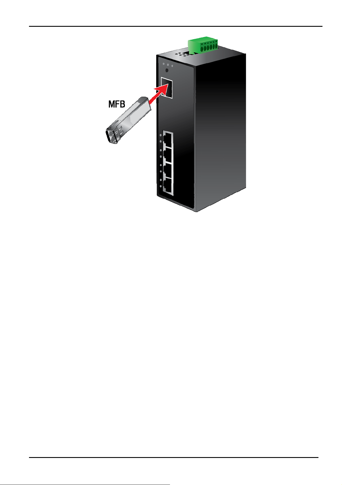
2.5.1 Installing the SFP transceiver (ISW-514PSF Only)
The sections describe how to insert an SFP transceiver into an SFP slot.
The SFP transceivers are hot-pluggable and hot-swappable. You can plug-in and out the transceiver to/from any SFP port
without having to power down the Switch/Media Converter. As the Figure 2-6 appears.
-21 -
Page 22
User’s Manual
Figure 2-6 Plug-in the SFP transceiver
Before connect the other switches, workstation or Media Converter.
1. Make sure both side of the SFP transceiver are with the same media type or WDM pair, for example: 100Base-FX to
100Base-FX, 100Base-BX20-U to 100Base-BX20-D.
2. Check the fiber-optic cable type match the SFP transceiver model.
¾ To connect to MFB-FX SFP transceiver, use the multi-mode fiber cable- with one side must be male duplex LC
connector type.
¾ To connect to MFB-F20/F40/F60/FA20/FB20 SFP transceiver, use the single-mode fiber cable-with one side
must be male duplex LC connector type.
Connect the fiber cable
1. Attach the duplex LC connector on the network cable into the SFP transceiver.
2. Connect the other end of the cable to a device – switches with SFP installed, fiber NIC on a workstation or a Media
Converter.
3. Check the LNK/ACT LED of the SFP slot of the switch / converter. Ensure that the SFP transceiver is operating
correctly.
4. Check the Link mode of the SFP port if the link failed. Co works with some fiber-NICs or Media Converters, set the Link
mode to “100 Force” is needed.
-22 -
Page 23
User’s Manual
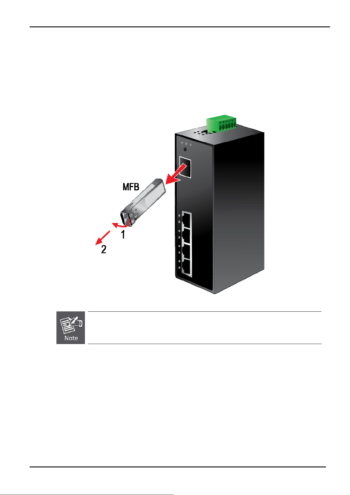
2.5.2 Remove the module
1. Make sure there is no network activity by consult or check with the network administrator. Or through the management
interface of the switch/converter (if available) to disable the port in advance.
2. Remove the Fiber Optic Cable gently.
3. Turn the handle of the MFB module to horizontal.
4. Pull out the module gently through the handle.
Figure 2-7 Pull Out the SFP transceiver
Never pull out the module without pull the handle or the push bolts on the module. Direct pull out the
module with violent could damage the module and SFP module slot of the device.
-23 -
Page 24

User’s Manual
3 MANAGEMENT
This chapter describes how to manage the Industrial PoE Switch Topics include:
- Overview
- Management method
- Logging on to the Industrial PoE Switch
3.1 Overview
The Industrial PoE Switch provides a user-friendly, Web interface. Using this interface, you can perform various device
configuration and management activities, including:
System
Power over Ethernet
Tools
3.2 Requirements
Network cables. Use standard network (UTP) cables with RJ-45 connectors.
Subscriber PC installed with Ethernet NIC (Network Card)
The operate system of subscriber PC that running Windows XP/2003, Vista, Windows 7, MAC OS X , Linux,
Fedora, Ubuntu or other platform compatible with TCP/IP protocols.
It is recommended to use Internet Explore 7.0 or above to access Industrial PoE Switch.
3.3 Management Method
User can manage the Industrial PoE Switch by Web Management via a network connection.
3.3.1 Web Management
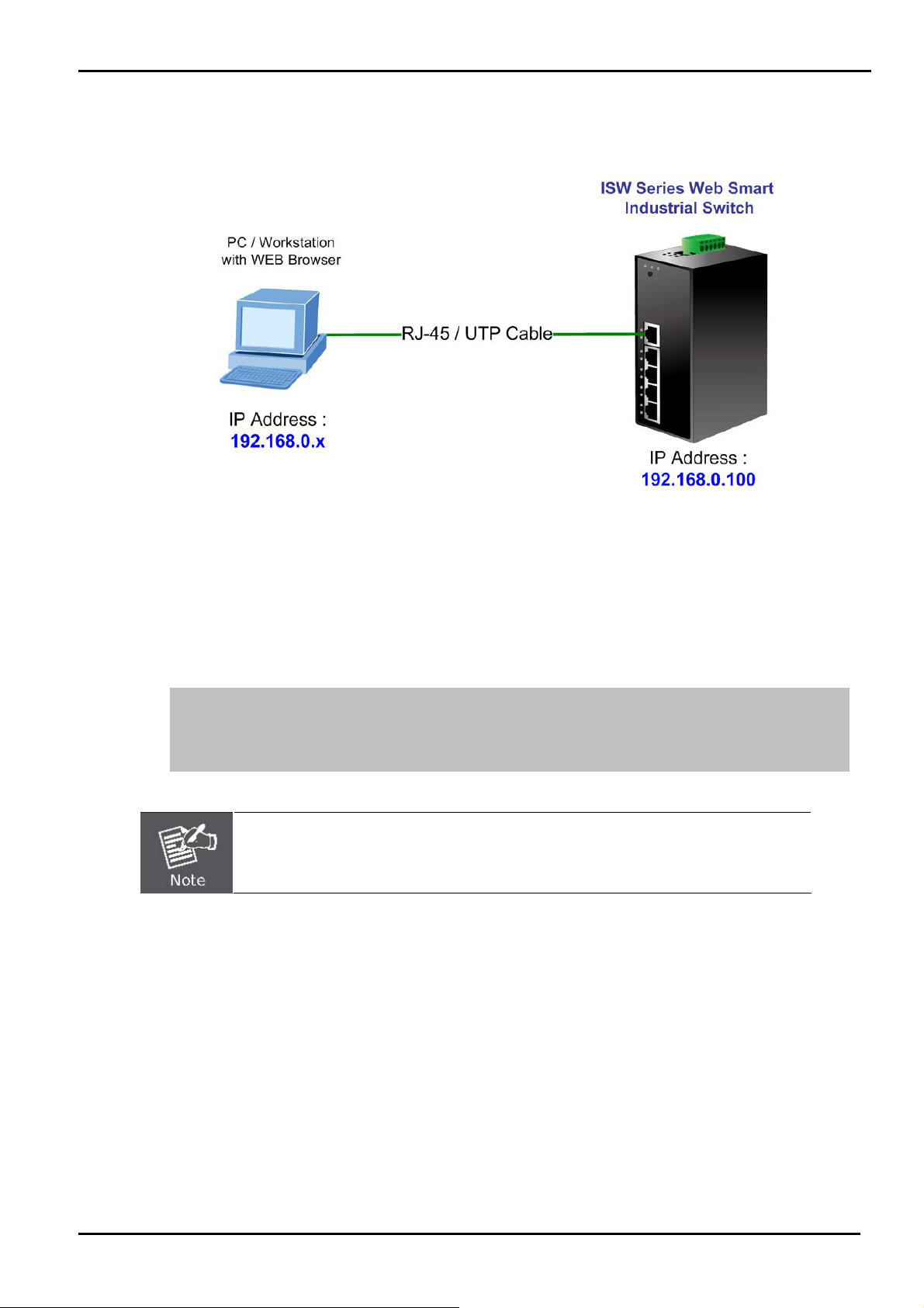
The Industrial PoE Switch can be configured through an Ethernet connection, make sure the manager PC must be set on
same the IP subnet address with the Industrial PoE Switch.
For example, if you have changed the default IP address of the Device to 192.168.99.123 with subnet mask 255.255.255.0
via console, then the manager PC should be set at 192.168.99.x (where x is a number between 2 and 254) with subnet
mask 255.255.255.0. Or you can use the factory default IP address 192.168.0.100 to do the relative configuration on
manager PC.
-24 -
Page 25
User’s Manual
1. Use Internet Explorer 7.0 or above Web browser. Enter IP address http://192.168.0.100 (the factory-default IP
address) to access the Web interface.
Figure 3-1 Web Management over Ethernet
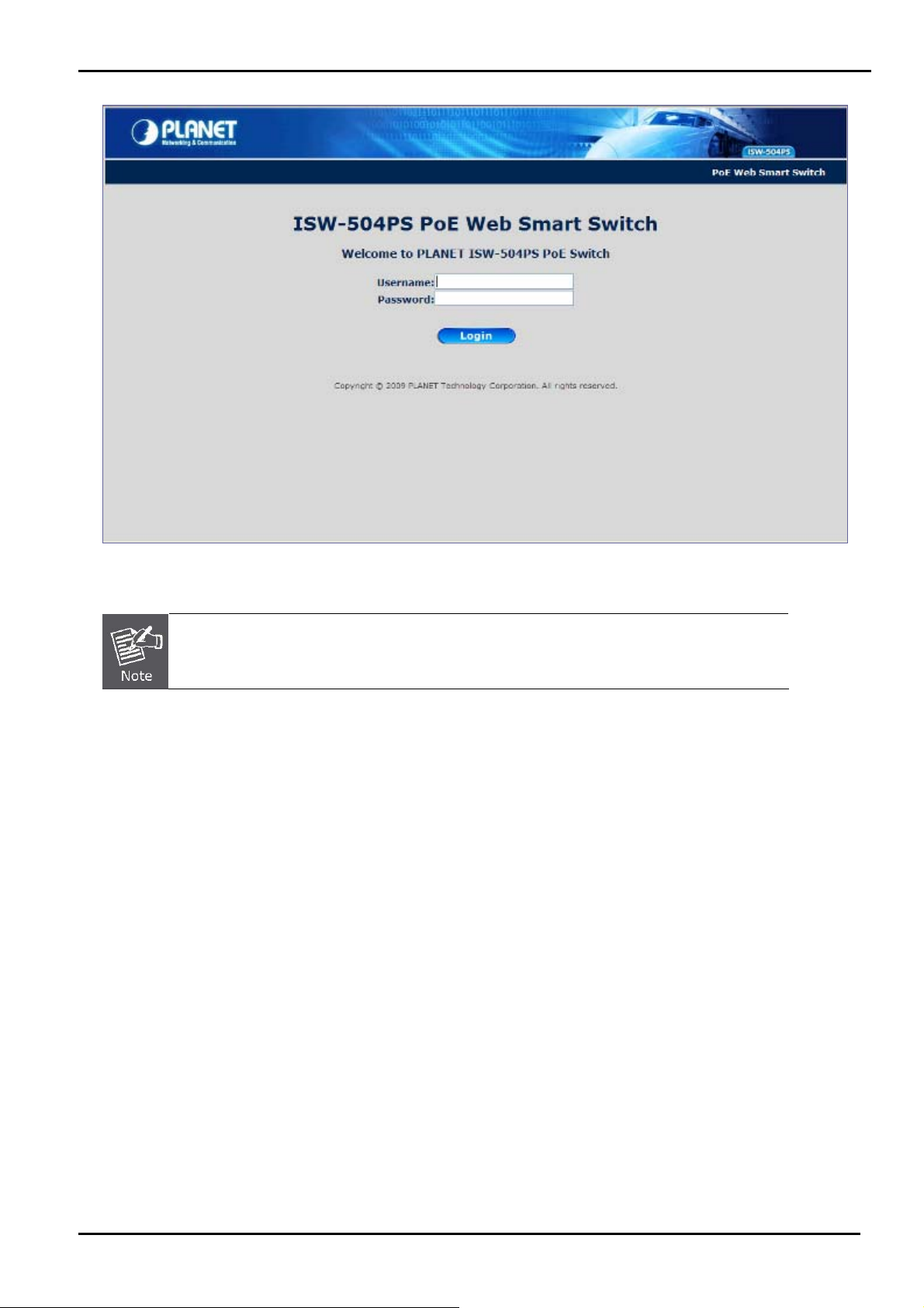
2. When the following login screen appears, please enter Planet’s default Username "admin" and Password “admin”
to login the main screen of Industrial PoE Switch. The login screen in Figure 3-2 appears.
3.
Default IP Address: 192.168.0.100
Default Account: admin
Default Password: admin
The following screen based on ISW-504PS, for ISW-514PS / ISW-514PS15 / ISW-514PSF.
-25 -
Page 26
User’s Manual
Figure 3-2 Web Login screen
1. For security reason, please changes and remembers the new password after this first setup.
2. Only accept command in lowercase letter under WEB interface.
-26 -
Page 27
User’s Manual
3.3.2 PLANET Smart Discovery Utility
For easily list the Industrial PoE Switch in your Ethernet environment, the Planet Smart Discovery Utility from user’s
manual CD-ROM is an ideal solution.
The following install instructions guiding you for run the Planet Smart Discovery Utility.
1. Deposit the Planet Smart Discovery Utility in administrator PC.
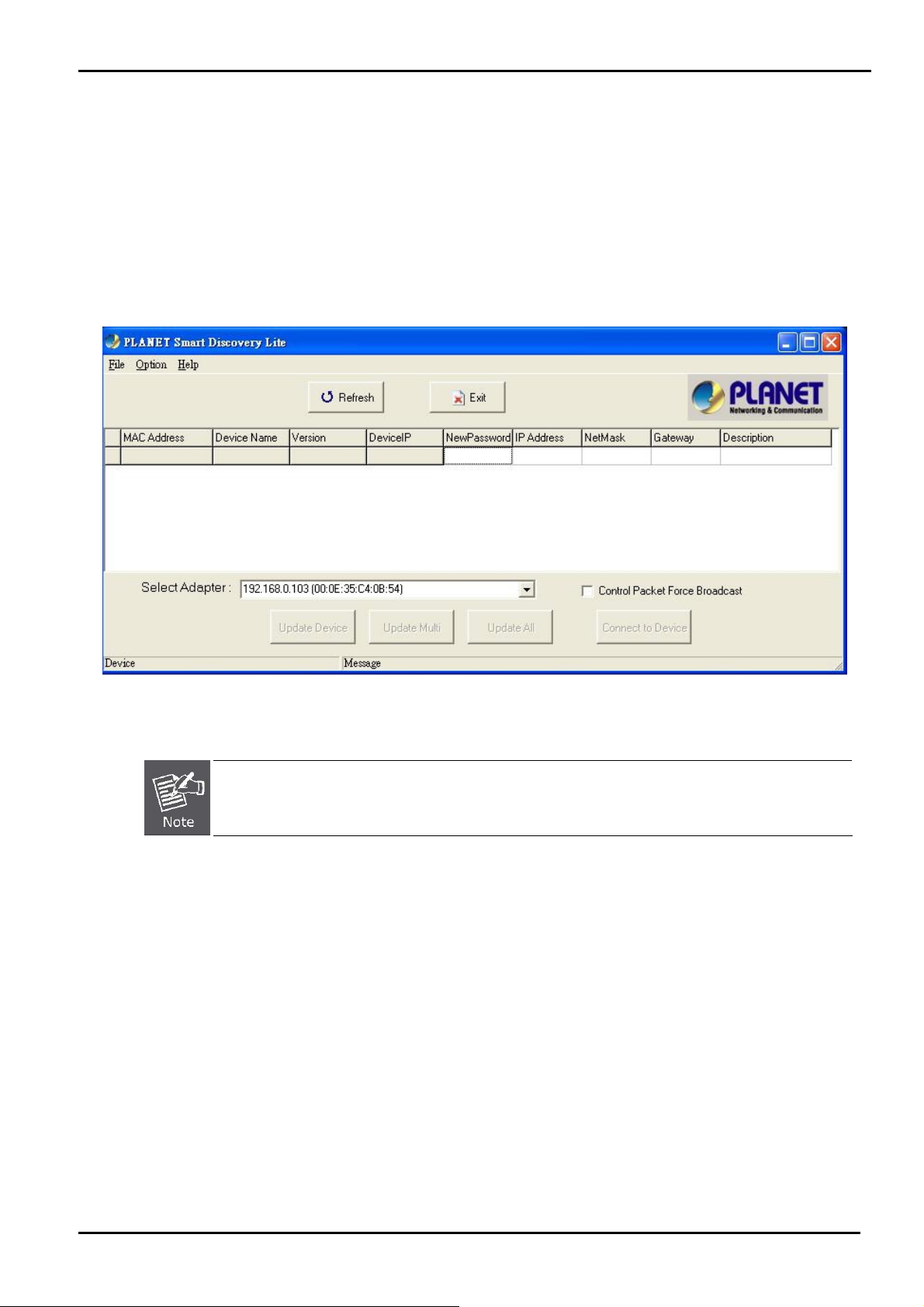
2. Run this utility and the following screen appears.
Figure 3-3 PLANET Smart Discovery Utility Screen
If there are two LAN cards or above in the same administrator PC, choose different LAN card by use the
“Select Adapter” tool.
3. Press “Refresh” button for list current connected devices in the discovery list, the screen is shown as follow.
-27 -
Page 28

Figure 3-4 PLANET Smart Discovery Utility Screen
User’s Manual
4. This utility shows all necessary information from the devices, such as MAC Address, Device Name, firmware version,
Device IP Subnet address, also can assign new password, IP Subnet address and description for the devices.
5. After setup completed, press “Update Device”, “Update Multi” or “Update All” button to take effect. The meaning
of the 3 buttons above are shown as below:
Update Device: update the current setting on one single device.
Update Multi: choose the multi-devices for updating the current setting.
Update All: use current setting on whole devices in the list.
The same functions mentioned above also can be finding in “Option” tools bar.
6. To click the “Control Packet Force Broadcast” function, it can allow assign new setting value to the Switch under
different IP subnet address.
7. “Connect to Device” button, the Web login window screen will appear, just like Figure 3-2.
8. Press “Exit” button to shutdown the Planet Smart Discovery Utility.
-28 -
Page 29

User’s Manual
4. WEB CONFIGURATION
The Industrial PoE Switch provides Web interface for PoE smart function configuration and make the Industrial PoE Switch
operate more effectively - They can configure through the Web Browser and the network administrator can manage and
monitor the Industrial PoE Switch from the local LAN. This section indicates how to configure the Industrial PoE Switch to
enable its smart function.
4.1 Main Menu
After a successful login, the main screen appears. The main screen displays the product name, the function menu, and the
main information in the center. As shown in Figure 4-1 and description on Table 4-1.
Figure 4-1 Main Menu Screen
System:
Port Management
VLAN
Quality of Service
Storm Control
Misc Configuration
Provide System information and configuration of Switch. Explained in section 4.3.
Setup Per Port mode, Rate Limit, Port description. Explained in section 4.4.
Configure VLAN Member / Port Configuration. Explained in section 4.5.
Mapping the packet level to classify the packets priority. Explained in section 4.6.
Enable Storm Control function to reduce broadcast packets on the Switch.
Explained in section 4.7.
Configure MAC address table aging, aging time mode and port flow control. Explained
-29 -
Page 30

in section 4.8.
User’s Manual
PoE Configuration
Logout:
Provide PoE Management configuration of Switch. Explained in section 4.9.
Provide Logout function of Switch.
Table 4-1 Descriptions of the Function items
4.2 Web Panel
On the left of the Web management page, the active panel displays the link status of management port and PoE ports.
LED Color Function
P1 Green
P2
Green
Indicate the power 1 has
power.
Indicate the power 2 has
power.
Indicate the either power
Green
Orange
1 or power 2 has no
power.
Indicate the link through
that port is successfully
established
Indicate the port is
providing 48V DC in-line
power. (1-4 ports)
FAULT
LNK/ACT Green
PoE In
Use
Table 4-2 Descriptions of the LED Objects
Figure 4-2 Left Side of Main Menu Screen(Light Indication)
-30 -
Page 31

4.3 System
The System function allows viewing System information, IP Configuration, Password Setting and etc.
As shown in Figure 4-3 and description on Table 4-3
User’s Manual
Figure 4-3 System Screen
The page includes the following information:
Object Description
System Information Display the MAC address, Software Version, Hardware Version, IP address, Subnet
Mask and Gateway. Explained in section 4.3.1
IP Configuration Allow to change the IP subnet address of Switch. Explained in section 4.3.2
Password Setting Allow to change the username and password of Switch. Explained in section 4.3.3
Firmware Upgrade Allow proceed firmware upgrade process of Switch. Explained in section 4.3.4
Configuration Setting Allow to restore / backup configuration of Switch and reset Switch to factory default.
Explained in section 4.3.
Configuration Backup Allow to download / upload the configuration file of Switch. Explained in section 4.3.6
Managed IP Allow to set the specific IP address to access the Web Smart Page. Explained in
section 4.3.7
Fault Relay Alarm Monitor the Power 1 and 2. Explained in section 4.3.8
Alert Trap Configuration Set up SNMP trap receiver’s IP address and trap event. Explained in section 4.3.9
System Reboot Allow reboot the Switch. Explained in section 4.3.10
Table 4-3 Descriptions of the System Column
-31 -
Page 32

User’s Manual
4.3.1 System Information
The System information will show the system MAC Address, Software Version, Hardware Version, IP Address, Subnet
Mask and Gateway. As shown in Figure 4-4 and description on Table 4-4
Figure 4-4 System Information screen
The page includes the following fields:
Object Description
MAC Address
Software Version
Hardware Version
IP Address
Subnet Mask
Gateway
Description
Temperature
Power Status
Specifies the Switch MAC address.
The current software version running on the Switch.
The current hardware version of the Switch.
The current IP Address of the Switch.
The current IP Subnet Mask value of the Switch.
The current Gateway value of the Switch.
The current description of the Switch.
The current Temperature of the Switch
The current Power units are Connect / Disconnect. Green: Connect Grey: Disconnect
Table 4-4 Descriptions of the System Information
-32 -
Page 33

User’s Manual
4.3.2 IP Configuration
This section provides DHCP Client, change the IP Address, Subnet Mask, Gateway and Description. As shown in Figure
4-5 and description on Table 4-5
Figure 4-5 IP Configuration Screen
The page includes the following configurable data:
Object Description
DHCP Client
IP Address The IP address of the Switch. The factory default value is 192.168.0.100.
Subnet Mask The IP subnet mask of the Switch. The factory default value is 255.255.255.0.
Gateway The default gateway of the Switch. The factory default value is 192.168.0.254.
Choose what the Switch should do following power-up: transmit a DHCP request, or manual
setting (Disable).
The DHCP client function only works if you haven't assigned a static IP address that different
than the Switch default IP. Once the default IP has been changed the DHCP will not effective
and the Switch will continue using the manually entered static IP. If you have changed the
Switch to a static IP address, you can set the IP address back to its default IP address or you
can reset the Switch back to factory default. And then you can enable the DHCP client function
to work.
The factory default is Disable.
Description
This field helps to identify the description of Switch.
Table 4-5 Descriptions of the IP Configuration
-33 -
Page 34

User’s Manual
4.3.3 Password Setting
This section provides password change Configuration of Industrial PoE Switch, please input the old password in “Old
Password” space and input the new password in “New Password” space then input the new password again in
“Confirm” space. After fill-in completed, please press “Apply” button to take effect and the Switch will logout
automatically. Please login web interface with new password. As shown in Figure 4-6 and description on Table 4-6
Figure 4-6 Password Setting Screen
The page includes the following configurable data:
Object Description
Login Name
Old Password
New Password Specifies the new password. The password will not display. As it entered “y” corresponding to
Confirm This confirms the new password. The password entered into this field must be exactly the same
Displays the login user name.
Enter the old password is required before entering the new password.
each character is displayed in the field.
(The maximum length is 16 characters)
as the password entered in the Password field.
Table 4-6 Descriptions of the Password Setting
4.3.4 Firmware Upgrade
This section provides firmware upgrade of Industrial PoE Switch. As shown in Figure 4-7. Please press “Update” button
to continue following firmware upgrade process.
-34 -
Page 35

User’s Manual
Figure 4-7 Firmware Upgrade screen
Please wait for two seconds and the page will turn to next firmware upgrade web page. As shown in Figure 4-8.
Figure 4-8 Firmware Upgrade screen
Please press “Browser” to locate the latest firmware of Switch that deposit in your PC and press “Upgrade” to start the
firmware upgrade process. As shown in Figure 4-9 and Figure 4-10.
-35 -
Page 36

User’s Manual
Figure 4-9 Firmware Upgrade screen(1)
Figure 4-10 Firmware Upgrade screen (2)
-36 -
Page 37

User’s Manual
1. Do not Power Off the Industrial PoE Switch during the firmware upgrade installation.
2. Do not Quit / Close the Firmware Upgrade page without press the “Upgrade” button - after the
image is loaded. Or the system won’t apply the new firmware. Users have to repeat the firmware
upgrade processes again.
Do not use Firefox or Windows Vista platform for ISW-504PS / ISW-514PS series firmware
upgrade or it might cause the firmware upgrade fail. Because of the short “HTTP respond time” for
Firefox and Windows Vista. While firmware upgrade, there is no immediately respond each to the
Firefox and Windows Vista, they will break the connection as http time out. It suggested to use the
Microsoft IE 7.0 at Windows XP platform for firmware upgrade.
-37 -
Page 38

User’s Manual
4.3.5 Configuration Setting
This function allows backup and restore the current configuration of Industrial PoE Switch, or reset the Industrial PoE
Switch to factory default. The description of the three items as follow and as shown in Figure 4-11.
■ Backup - To backup / save the current configuration to the storage block on this Switch.
■ Restore – To restore the previous backup configuration from the storage block.
■ Factory – To reset the Industrial PoE Switch back to the factory default mode.
Figure 4-11 Configuration Setting screen
■ Backup
All current configurations (except IP Configuration) will save to Industrial PoE Switch when press the “Backup” button. As
shown in Figure 4-12.
Figure 4-12 Configuration Setting\Backup screen
-38 -
Page 39

If finish the Backup and work successfully, it will show a message that tells you it done. As shown in Figure 4-13.
Figure 4-13 Configuration backup successes screen
Restore
User’s Manual
The Industrial PoE Switch will restore to previous backup/saved configuration while the “Restore” button be pressed. And
please note that once the Restore button be pressed, Web interface will disconnected for a while. Reload the Web browser
to re-login the system.
Figure 4-14 Configuration restore screen
Factory Reset
The Factory Reset button can reset the Industrial PoE Switch back to the factory default mode. Be aware that the entire
configuration will be reset, and the IP address of the Industrial PoE Switch will be set to “192.168.0.100”.
Figure 4-15 Factory Reset screen
Once the Factory Reset item is pressed, the screen in Figure 4-16 appears.
-39 -
Page 40

Figure 4-16 Factory Reset screen
4.3.6 Configuration Backup
This function allows downloading the current configuration as a file. The filename extension will be “cfg” file.
If already downloads 3 different setting of files as file 1, file 2 and file 3. As showed in Figure 4-17.
The Upload function allows selecting any one of them to restore back the setting.
■ Upload - To select the file and restore back the configuration
■ Download – To download the current configuration as a file and save on your PC
User’s Manual
Figure 4-17 Configuration Backup Screen
-40 -
Page 41

4.3.7 Managed IP
The function allows setting 5 specific IP address to access the Industrial PoE Switch. As shown in Figure 4-18.
User’s Manual
Figure 4-18 Managed IP Screen
4.3.8 Fault Relay Alarm
This Function allows controlling the Power Failure. If the terminal block connector has connected the fault alarm contacts
(3 & 4). The setting just like below picture. For example: when one of the power failure then it will trigger the warning device
and sound the alarm. As shown in Figure 4-19.
Figure 4-19 Fault Relay Alarm Screen
-41 -
Page 42

User’s Manual
4.3.9 Alert Trap Configuration
This function displays the Industrial PoE Switch alert trap configuration; include “Enable” or “Disable” the trap mode and
set the alert IP address. As shown in Figure 4-20 and description on Table 4-7.
Trap mode
Alert IP address
Trap event
Figure 4-20 Alert Trap Configuration screen
Object Description
Can choose enable/disable to get the trap
Assign one IP address of host to receive SNMP trap from the device.
Choose the events to send the SNMP trap. The trap events include:
Cold Start
Login Fail
Password changed
IP Changed
Link up
Link down
PoE Alert
Table 4-7 Descriptions of the Alert Trap Configuration
-42 -
Page 43

User’s Manual
4.3.10 System Reboot
This section provides reboot the Industrial PoE Switch, after choose this function and the following screen appears in
Figure 4-21. Please press “OK” button to take effect and the Industrial PoE Switch will reboot and ask you to re-login web
interface with correct user name “admin” and password, as shown in Figure 4-22 and Figure 4-23.
Figure 4-21 reboot system Web Page screen
Figure 4-22 System Rebooting Web Page screen
Figure 4-23 Login Web Page screen
-43 -
Page 44

User’s Manual
4.4 Port Management
In this chapter, there are three sub-functions can be configure and monitor about network interfaces:
Port Configuration
Port Status
Port Security
4.4.1 Port Configuration
This section introduces detail settings of per port of Industrial PoE Switch as shown in Figure 4-24 and Table 4-8 describes
the Port Setup objects of Industrial PoE Switch.
Figure 4-24 Port Setup Web Page screen
The page includes the following configurable data:
Object Description
Port Indicate port 1 to port 5.
Link Display the current Port link status.
Mode Allow configuration the port speed and operation mode. Draw the menu bar to
select the mode
• Auto Speed - Setup Auto negotiation
• 10 Half - Force sets 10Mbps/Half-Duplex mode
• 10 Full - Force sets 10Mbps/Full-Duplex mode
• 100 Half - Force sets 100Mbps/Half-Duplex mode
• 100 Full - Force sets 100Mbps/Full-Duplex mode
• Disable - Shutdown the port manually
Default: Auto Speed
Ingress Rate Limit
The value of inbound traffic limitation in kilobit-per-second (kbps).
Default : No Limit
-44 -
Page 45

User’s Manual
• No Limit
• 128K
• 256K
• 512K
Egress Shaping
Description Allow to set value for port Description, This column accepts characters —“0-9,
Table 4-8 Descriptions of the Port Setup screen Objects
When the ports are being set as fixed 100M Full, 100M Half, 10M Full, and 10M Half-speed
modes, the Auto-MDIX function will disable.
The value of outbound traffic limitation in kilobit-per-second (kbps).
Default : No Limit
• No Limit
• 128K
• 256K
• 512K
A-Z, a-z, @, - _ and * “
Maximum: 8 characters
• 1M
• 2M
• 4M
• 8M
• 1M
• 2M
• 4M
• 8M
4.4.2 Port Status
This section provides current status of each port from Industrial PoE Switch, as shown in Figure 4-25.
Figure 4-25 Port Status Web Page screen
-45 -
Page 46

User’s Manual
4.4.3 Port Security
The Layer 2 MAC address learning function can be per-port disable for security management purposes. When the port is in
security mode, the port will be "locked" without permission of address learning.
For Example:
1. Enable the Port 1 Security and the port will record the first receiving packet's source MAC
address as a "Security MAC address ".
2. A security port only allows that packet which has the "Security MAC address" to active on.
Object Description
Port
Port Security Enable
Check Box
Figure 4-26 Port Security screen
Which selecting this option locks the specified interface.
Enable Source MAC address lock function on specified port. By which locks the
port using the classic lock mechanism. The port is immediately locked without
permission of address learning.
Table 4-9 Descriptions of the Port Security screen Objects
1. The Device will reboot after enable Port Security.
2. After reboot, each port will record the first receiving packet's source MAC address as a "Security
MAC address ".
3. A security port only allows that packet which has the "Security MAC address" to active on.
-46 -
Page 47

User’s Manual
4.5 VLAN
A Virtual LAN (VLAN) is a logical network grouping that limits the broadcast domain. It allows you to isolate network traffic
so only members of the VLAN receive traffic from the same VLAN members. Basically, creating a VLAN from a switch is
logically equivalent of reconnecting a group of network devices to another Layer 2 switch. However, all the network
devices are still plug into the same switch physically.
The ISW-504PS / ISW-514PS series Ethernet Switch supports 802.1Q (tagged-based) and Port-Base VLAN setting in
web management page. The default configuration of VLAN setting is “Disable”.
Port-based VLAN
Port-based VLAN limit traffic that flows into and out of switch ports. Thus, all devices connected to a port are members of
the VLAN(s) the port belongs to, whether there is a single computer directly connected to a switch, or an entire
department.
On Port-based VLAN, NIC do not need to be able to identify 802.1Q tags in packet headers. NIC send and receive normal
Ethernet packets. If the packet's destination lies on the same segment, communications take place using normal Ethernet
protocols. Even though this is always the case, when the destination for a packet lies on another switch port, VLAN
considerations come into play to decide if the packet is dropped by the Switch or delivered.
IEEE 802.1Q VLAN
IEEE 802.1Q (tagged) VLAN are implemented on the Switch. 802.1Q VLAN require tagging, which enables them to span
the entire network (assuming all switches on the network are IEEE 802.1Q-compliant).
VLAN allow a network to be segmented in order to reduce the size of broadcast domains. All packets entering a VLAN will
only be forwarded to the stations (over IEEE 802.1Q enabled switches) that are members of that VLAN, and this includes
broadcast, multicast and unicast packets from unknown sources.
VLAN can also provide a level of security to your network. IEEE 802.1Q VLAN will only deliver packets between stations
that are members of the VLAN. Any port can be configured as either tagging or untagging. The untagging feature of IEEE
802.1Q VLAN allows VLAN to work with legacy switches that don't recognize VLAN tags in packet headers. The tagging
feature allows VLAN to span multiple 802.1Q-compliant switches through a single physical connection and allows
Spanning Tree to be enabled on all ports and work normally.
Some relevant terms:
Tagging - The act of putting 802.1Q VLAN information into the header of a packet.
Untagging - The act of stripping 802.1Q VLAN information out of the packet header.
802.1Q VLAN Tags
The figure below shows the 802.1Q VLAN tag. There are four additional octets inserted after the source MAC address.
Their presence is indicated by a value of 0x8100 in the Ether Type field. When a packet's Ether Type field is equal to
0x8100, the packet carries the IEEE 802.1Q/802.1p tag. The tag is contained in the following two octets and consists of 3
bits of user priority, 1 bit of Canonical Format Identifier (CFI - used for encapsulating Token Ring packets so they can be
-47 -
Page 48

User’s Manual
carried across Ethernet backbones), and 12 bits of VLAN ID (VID). The 3 bits of user priority are used by 802.1p. The VID
is the VLAN identifier and is used by the 802.1Q standard. Because the VID is 12 bits long, 4094 unique VLAN can be
identified.
The tag is inserted into the packet header making the entire packet longer by 4 octets. All of the information originally
contained in the packet is retained.
IEEE 802.1Q Tag
User Priority CFI VLAN ID (VID)
3 bits 1 bits 12 bits
TPID (Tag Protocol Identifier) TCI (Tag Control Information)
2 bytes 2 bytes
Preamble
Destination
Address
6 bytes 6 bytes 4 bytes 2 bytes 46-1517 bytes 4 bytes
Source
Address
VLAN TAG
Ethernet
Type
Data FCS
The Ether Type and VLAN ID are inserted after the MAC source address, but before the original Ether Type/Length or
Logical Link Control. Because the packet is now a bit longer than it was originally, the Cyclic Redundancy Check (CRC)
must be recalculated.
Adding an IEEE 802.1Q Tag
Dest. Addr. Src. Addr. Length/E. type Data Old CRC
Original Ethernet
Dest. Addr. Src. Addr. E. type Tag Length/E. type Data New CRC
Priority CFI VLAN ID
New Tagged Packet
Port VLAN ID
Packets that are tagged (are carrying the 802.1Q VID information) can be transmitted from one 802.1Q compliant network
device to another with the VLAN information intact. This allows 802.1Q VLAN to span network devices (and indeed, the
entire network – if all network devices are 802.1Q compliant).
Every physical port on a switch has a PVID. 802.1Q ports are also assigned a PVID, for use within the switch. If no VLAN
are defined on the switch, all ports are then assigned to a default VLAN with a PVID equal to 1. Untagged packets are
assigned the PVID of the port on which they were received. Forwarding decisions are based upon this PVID, in so far as
VLAN are concerned. Tagged packets are forwarded according to the VID contained within the tag. Tagged packets are
also assigned a PVID, but the PVID is not used to make packet forwarding decisions, the VID is.
Tag-aware switches must keep a table to relate PVID within the switch to VID on the network. The switch will compare the
VID of a packet to be transmitted to the VID of the port that is to transmit the packet. If the two VID are different the switch
will drop the packet. Because of the existence of the PVID for untagged packets and the VID for tagged packets, tag-aware
and tag-unaware network devices can coexist on the same network.
-48 -
Page 49

User’s Manual
A switch port can have only one PVID, but can have as many VID as the switch has memory in its VLAN table to store
them.
Because some devices on a network may be tag-unaware, a decision must be made at each port on a tag-aware device
before packets are transmitted – should the packet to be transmitted have a tag or not? If the transmitting port is connected
to a tag-unaware device, the packet should be untagged. If the transmitting port is connected to a tag-aware device, the
packet should be tagged.
Default VLAN
The Switch initially configures one VLAN, VID = 1, called "default." The factory default setting assigns all ports on the
Switch to the "default". As new VLAN are configured in Port-based mode, their respective member ports are removed
from the "default."
The Switch supports SVL (Shared VLAN Learning), all VLAN groups share the same Layer
2 learned MAC address table.
1 No matter what basis is used to uniquely identify end nodes and assign these nodes
VLAN membership, packets cannot cross VLAN without a network device performing a
routing function between the VLAN.
2 The Switch supports Port-based VLAN and IEEE 802.1Q VLAN. The port untagging
function can be used to remove the 802.1 tag from packet headers to maintain
compatibility with devices that are tag-unaware.
-49 -
Page 50

User’s Manual
4.5.1 VLAN Group
The VLAN Group page contains fields for managing VLAN mode of the Industrial PoE Switch and setting ports that are part
of a VLAN. The port default VLAN ID (PVID) is configured on the VLAN Port Configuration page. All untagged packets
arriving to the device are tagged by the ports PVID. As shown in Figure 4-27 & 4-28.
The VLAN mode had three modes:
■ Disable (No VLAN)
■ Port-Based VL AN
■ 802.1Q VLAN
The Industrial PoE Switch supports Port-based VLAN and 802.1Q VLAN (Tagged-based) in Web management page. In
the default configuration, VLAN support is “Disable”.
Figure 4-27 VLAN Group screenshot
4.5.1.1 Port-Based VLAN
By setting the VLAN Type with Port-Based, Port-Based VLAN is enabled and 802.1Q VLAN tagging is ignored. The VLAN
group classification of an incoming packet on a Port-Based VLAN is defined by the VLAN group table.
A port is limited to communicate with other ports within the same group when the function is enabled and configured.
Frame will be limited in a VLAN group and will not be forwarded out this VLAN group. A port can be assigned to one or
more VLAN groups.
-50 -
Page 51

User’s Manual
Figure 4-28 VLAN Group – Port-Based VLAN screen
When Port-Based VLAN mode is selected, the displayed page includes the following configurable data. Description on
Table 4-10
Object Description
VLAN Type
Management VLAN
Group
There’re three VLAN mode support – 802.1Q VLAN, Port-Bas VLAN and No
VLAN.
• 802.1Q – Packets income will be tagged with VID as the PVID setting. All ports
on the switch belong to default VLAN (VID 1).
• Port-Base - Packets can only be broadcast among other members of the same
VLAN group. Note all unselected ports are treated as belonging to the default
system VLAN.
• Disable - Forbidden ports are not included in the VLAN
If Port-based VLAN are enabled, then VLAN-tagging feature is ignored.
At Port-Based VLAN mode, up to 5 VLAN groups can be configured.
Member Port
Select the physical interface for which you want to display or configure data.
Table 4-10 Descriptions of the Port-Based VLAN item
-51 -
Page 52

User’s Manual
4.5.1.2 IEEE 802.1Q VLAN
This function group individual ports into a small “Virtual” network of their own to be independent of the other ports. By
setting the VLAN Type with 802.1Q, IEEE 802.1Q tag-based VLAN is enabled. VLAN classification is the first step before
VLAN table lookup. The PoE Switch will check the VID value of the received packets and the VLAN table ingress / egress
rule, then forwards the packets to valid destination ports.
Select “802.1Q VLAN” and press “Apply” button, to enable the IEEE 802.1Q VLAN function then continue configure 16
802.1Q VLAN groups as your request. After setup completed, please press “Apply” to take effect. As shown in Figure
4-29 and description on Table 4-11
Figure 4-29 VLAN Group – 802.1Q VLAN screen
The page includes the following fields:
Object Description
VLAN Type
There’re two VLAN mode support – 802.1Q VLAN and Port-Based VLAN
• 802.1Q – Packets income will be tagged with VID as the PVID setting. All ports
• Port-Based - Packets can only be broadcast among other members of the
on the switch belong to default VLAN (VID 1).
same VLAN group. Note all unselected ports are treated as belonging to the
default system VLAN.
-52 -
Page 53

• Disable - Forbidden ports are not included in the VLAN
User’s Manual
• VL AN Group
• VID
• Member Port
1. The VID value of each VLAN group must follow the rule -> there is an interval value 16 of
available VID value. For example, VLAN 2 VID must be 2, 18, 34, ….; VLAN 3 VID must be 3,
19, 35…
The VLAN entry index. Select the column to specify the VLAN group for VLAN
member ports configure.
The Switch supports up to 16 active VLAN groups.
Specify the VLAN Identifier for the 802.1Q VLAN.
The available range of the VID is (1 to 4094).
( 802.1Q mode only)
Select the physical interface for which you want to add or remove from the specify
VLAN group. Checked the Member box to select the members for the VLAN
group. Number 1-5 is the Physical interface ID of the PoE Switch.
After setup completed, please press “Apply” to take affect.
Table 4-11 Descriptions of the 802.1Q VLAN item
2. There is no way to delete a VLAN group on the PoE Switch. Just cancel all the check box from
Port-1 to Port-5 to make the VLAN group be not active.
-53 -
Page 54

User’s Manual
4.5.2 VLAN Per Port Setting
The Industrial PoE Switch inserts or removes a tag of frame if Tag / UnTag function is enabled. The operation is illustrated
as follows. As shown in Figure 4-30 and description on Table 4-12.
Understand nomenclature of the 802.1Q VLAN aware Switch
Tagging and Untagging
Every port on an 802.1Q compliant switch can be configured as tagging or untagging.
。 Tagging: Ports with tagging enabled will put the VID number, priority and other VLAN information into the header of
all packets that flow into those ports. If a packet has previously been tagged, the port will not alter the packet, thus
keeping the VLAN information intact. The VLAN information in the tag can then be used by other 802.1Q compliant
devices on the network to make packet-forwarding decisions.
。 Untagging: Ports with untagging enabled will strip the 802.1Q tag from all packets that flow into those ports. If the
packet doesn't have an 802.1Q VLAN tag, the port will not alter the packet. Thus, all packets received by and
forwarded by an untagging port will have no 802.1Q VLAN information. (Remember that the PVID is only used
internally within the Switch). Untagging is used to send packets from an 802.1Q-compliant network device to a
non-compliant network device.
Frame Income
Frame Leave
Leave port is tagged Frame remains tagged
Leave port is untagged Tag is removed
Income Frame is tagged Income Frame is untagged
Tag is inserted
(Tag=PVID or Original VID be remained)
Frame remain untagged
(Tag=PVID be removed)
Figure 4-30 VLAN Per port setting screen
-54 -
Page 55

The page includes the following fields:
Object Description
User’s Manual
Port
Link Type
PVID
Indicate the physical interface for which you want to display or configure data.
Allow 802.1Q Untagged or Tagged VLAN for selected port.
When adding a VLAN to selected port, it tells the switch whether to keep or
remove the tag from a frame on egress.
• Untag: outgoing frames without VLAN-Tagged.
• Tagged: outgoing frames with VLAN-Tagged.
( 802.1Q mod only)
Allow assign PVID for selected port. The range for the PVID is 1-4094
The PVID will be inserted into all untagged frames entering the ingress port. The
PVID must as same as the VLAN ID that the port belong to VLAN group, or the
untagged traffic will be dropped.
Table 4-12 Descriptions of the 802.1Q VLAN Per Port item
-55 -
Page 56

User’s Manual
4.5.3 VLAN setting example:
4.5.3.1 Two separate 802.1Q VLAN
The diagram shows how the Industrial PoE Switch handle Tagged and Untagged traffic flow for two VLANs. VLAN Group
2 and VLAN Group 3 are separated VLAN. Each VLAN isolate network traffic so only members of the VLAN receive traffic
from the same VLAN members. As shown in Figure 4-31 and Table 4-13 describes the port configuration of Industrial PoE
Switch.
Figure 4-31 two separate VLAN diagram
VLAN Group VID Untagged Members Tagged Members
VLAN Group 1 1 Port-5 N/A
VLAN Group 2 2 Port-1,Port-2 Port-2
VLAN Group 3 3 Port-3,Port-4 Port-4
Table 4-13 VLAN and Port Configuration
The scenario described as follow:
Untagged packet entering VLAN 2
1. While [PC-1] transmit an untagged packet enters Port-1, the switch will tag it with a VLAN Tag=2. [PC-2] will
received the packet through Port-2.
2. [PC-3] and [PC-4] received no packet.
3. While the packet leaves Port-2, it will keep as a tagged packet with VLAN Tag=2.
-56 -
Page 57

Tagged packet entering VLAN 2
4. While [PC-2] transmit a tagged packet with VLAN Tag=2 enters Port-2, [PC-1] will received the packet
through Port-1.
5. While the packet leaves Port-1, it will be stripped away it tag becoming an untagged packet.
Untagged packet entering VLAN 3
1. While [PC-3] transmit an untagged packet enters Port-3, the switch will tag it with a VLAN Tag=3. [PC-4] will
received the packet through Port-4.
2. While the packet leaves Port-4, it will keep as a tagged packet with VLAN Tag=3.
At this example, VLAN Group 1 just set as default VLAN, but only focus on VLAN 2 and VLAN 3
traffic flow
User’s Manual
Setup steps
1. Create VLAN Group
Set VLAN Group 1 = default-VLAN with VID (VLAN ID)=1
Add two VLANs – VLAN 2 and VLAN 3
VLAN Group 2 with VID=2
VLAN Group 3 with VID=3
2. Assign VLAN Member :
VLAN 2 : Port-1and Port-2
VLAN 3 : Port-3 and Port-4
VLAN 1 : Port 5
-57 -
Page 58

User’s Manual
Figure 4-32 Assign VLAN 2 Group members screen
Remember to remove the Port 1 – Port 4 from VLAN 1 membership, since the Port 1 – Port 4 had been assigned to
VLAN 2 and VLAN 3.
It’s import to remove the VLAN members from VLAN 1 configuration. Or the ports would become
overlap setting. ( About the overlapped VLAN configuration, see next VLAN configure sample)
3. Assign PVID for each port:
Port-1 and Port-2: PVID=2
Port-3 and Port-4 : PVID=3
Port-5: PVID=1
4. Enable VLAN Tag for specific ports
Link Type: Port-2 (VLAN-2) and Port-4 (VLAN-3) be set to “Tagged”.
The Per Port VLAN configuration in Figure 4-33 appears.
-58 -
Page 59

User’s Manual
Figure 4-33 Port 1-Port 5 VLAN Configuration
4.5.3.2 Two VLANs with overlap area
Follow the example of 4.5.3.1. There’re two exist separate VLANs – VLAN 2 and VLAN 3, and the PCs of each VLANs are
not able to access each other of different VLANs. But they all need to access with the same server. The screen in Figure
4-34 appear. This section will show you how to configure the port for the server – that could be accessed by both VLAN 2
and VLAN 3.
Figure 4-34 A Server connect to the VLAN overlap area
-59 -
Page 60

User’s Manual
1. Specify Port-5 on the device to connect to the server.
2. Assign Port-5 to both VLAN 2 and VLAN 3 at the VLAN Member configuration page. The screen in Figure 4-35
appears.
Figure 4-35 VLAN overlap port setting
3. Define a VLAN 1 as a “Public Area” that overlapping with both VLAN 2 members and VLAN 3 members.
-60 -
Page 61

User’s Manual
Figure 4-36 VLAN 1 – The public area member assigning
4. Setup Port-5 with “PVID=1” at VLAN per Port Configuration page. The screen in Figure 4-37 appears.
Figure 4-37 Setup Port-5 with PVID-1
That is, although the VLAN 2 members: Port-1 to Port-2 and VLAN 3 members: Port-3 to Port-4, are also belonging to
VLAN 1. But with different PVID settings, packets form VLAN 2 or VLAN 3 is not able to access to the other VLAN.
-61 -
Page 62

User’s Manual
4.5.3.3 Port-based VLAN setting example:
VLAN scenario
1. Port-5 is the file server port for all the workstations
2. Port-1 to Port-4 is different devices that do not need to see each other
Setup steps
1. Port Setting
1.1 Assign VLAN 2 for the second VLAN group with Port-1 and Port-5
1.2 Repeat the same steps for Port-2 to Port-7. i.e. 2 & 5, 3 & 5 … 4 & 5
After the above steps Port-1 to Port-4 is being separated physically due to it belongs to different VLAN groups
(different VLAN). However, they all can access Port-5 because of Port-5 is using PVID 1 to communicate with
Port-1 to Port-4.
Figure 4-38 Port-Based VLAN setting example
-62 -
Page 63

User’s Manual
4.6 Quality of Service
Quality of Service (QoS) is an advanced traffic prioritization feature that allows you to establish control over network
traffic. QoS enables you to assign various grades of network service to different types of traffic, such as multi-media, video,
protocol-specific, time critical, and file-backup traffic.
QoS reduces bandwidth limitations, delay, loss, and jitter. It also provides increased reliability for delivery of your data and
allows you to prioritize certain applications across your network. You can define exactly how you want the switch to treat
selected applications and types of traffic.
You can use QoS on your system to:
• Classifying traffic based on packet attributes.
• Assigning priorities to traffic (for example, to set higher priorities to time-critical or business-critical applications).
• Applying security policy through traffic filtering.
• Provide predictable throughput for multimedia applications such as video conferencing or voice over IP by
minimizing delay and jitter.
• Improve performance for specific types of traffic and preserve performance as the amount of traffic grows.
• Reduce the need to constantly add bandwidth to the network.
• Manage network congestion.
The QoS page of the Industrial PoE Switch contains three types of QoS mode - the 802.1p mode, DSCP mode or
Port-base mode can be selected. Both the three mode rely on predefined fields within the packet to determine the output
queue.
802.1p Tag Priority Mode –The output queue assignment is determined by the IEEE 802.1p VLAN priority tag.
IP DSCP Mode - The output queue assignment is determined by the TOS or DSCP field in the IP packets.
Port-Base Priority Mode – Any packet received from the specify high priority port will treated as a high priority
packet.
The Industrial PoE Switch supports two priority level queue, the queue service rate is based on the WRR(Weight Round
Robin) alorithm. The WRR ratio of high-priority and low-priority can be set to “4:1 and 8:1.
The screen in Figure 4-39 shows the Quality of Service configuration page.
-63 -
Page 64

User’s Manual
Figure 4-39 Quality of Service screen
4.6.1 802.1p Tag Priority Mode
QoS settings allow customization of packet priority in order to facilitate delivery of data traffic that might be affected by
latency problems. When 802.1p Tag Priority is applied, the Industrial PoE Switch recognizes 802.1Q VLAN tag packets
and extracts the VLAN tagged packets with User Priority value.
802.1Q Tag and 802.1p priority
User Priority CFI VLAN ID (VID)
3 bits 1 bits 12 bits
TPID (Tag Protocol Identifier) TCI (Tag Control Information)
2 bytes 2 bytes
Preamble
Destination
Address
6 bytes 6 bytes 4 bytes 2 bytes 46-1517 bytes 4 bytes
Source
Address
VLAN TAG
Ethernet
Type
Data FCS
Figure 4-40 802.1p Tag Priority
The IEEE 802.1p Tag Priority specification uses 2 priority levels to classify data packets. The screen in Figure 4-41
appears.
-64 -
Page 65

User’s Manual
Figure 4-41 QoS - 802.1p Tag Priority screen
The page includes the following fields:
• Object • Description
• QoS Mode
Weighted Round
Robin Ratio
The Industrial PoE Switch had defined the VLAN tagged packets with User Priority value 4~7 are treated as high priority
packets, and the other User Priority values (0~3) as low priority packets. The User Priority follows the IEEE 802.1p
standard).
The draw menu allows customization of QoS mode for Traffic classifiers.
• 802.1p Tag Priority
• IP DSCP
• Port-Base Priority
Weighted Round Robin ratio setting of priority queue.
The frame service rate of High-Priority queue to Low-Priority queue options are
shown as below:
• Highest:Lowest=4:1
• Highest:Lowest=8:1
Table 4-14 Descriptions of the 802.1p Tag priority
IEEE 802.1p priority value from VLAN tag
High Priority
Low Priority
User priority values= 4~7
User priority values= 0~3
-65 -
Page 66

User’s Manual
4.6.2 DSCP QoS Mode
DiffServ Code Point (DSCP) - is the traffic prioritization bits within an IP header that are encoded by certain applications
and/or devices to indicate the level of service required by the packet across a network.
4 bit 4 bit 6 bit 2 bit
VER=0100 Header Size
DiffServ RES
Preamble
Destination
Address
6 bytes 6 bytes 4 bytes 2 bytes 2 bytes 46-1517 bytes 4 bytes
Source
Address
VLAN TAG
(Optional)
Ethernet Type
(0800)
Data FCS
Figure 4-42 IPv4 frame format
The Quality of Service page provides fields for defining output queue to specific DSCP fields. When TCP/IP’s TOS/DSCP
mode is applied, the PoE Switch recognizes TCP/IP Differentiated Service Codepoint (DSCP) priority information from the
DS-field defined in RFC-2474. Select the QoS mode to IP DSCP, the DSCP to priority mapping page appears, as the
Figure 4-43 shows.
-66 -
Page 67

User’s Manual
The page includes the following fields:
• Object • Description
• QoS Mode
Weighted Round
Robin Ratio
The draw menu allows customization of QoS mode for Traffic classifiers.
• 802.1p Tag Priority
• IP DSCP
• Port-Base Priority
Weighted Round Robin ratio setting of priority queue.
The frame service rate of High-Priority queue to Low-Priority queue options are
shown as below:
• Highest:Lowest=4:1
• Highest:Lowest=8:1
Table 4-15 Descriptions of the IP DSCP
Figure 4-43 DSCP QoS Configuration screen
-67 -
Page 68

User’s Manual
DSCP are defined in RFC-2597 for classifying traffic into different service classes. The Industrial PoE Switch extracts the
code point value of the DS field from IPv4 packets and identifies the priority of the incoming IP packets following the
definitions listed below:
Suggest High Priority IP DSCP Value
EF
High Priority
Low Priority
DSCP: Differentiated Services Code Point
EF: Expected Forwarding
AF: Assured Forwarding
DSCP 46
(101110)
Other DSCP values
AF11
DSCP 10
(001010)
AF21
DSCP 18
(010010)
AF31
DSCP 26
(011010)
AF41
DSCP 34
(100010)
-68 -
Page 69

User’s Manual
4.6.3 Port-Based Priority Mode
When Port-Based priority is applied, any packets received from a high priority port will be treated as a high priority packet.
Select the QoS mode to Port-Based Priority, the Port ID to queue mapping configuration page appears, as the Figure 4-44
shows.
Figure 4-44 QoS – Port-Based Priority Configuration screen
The page includes the following fields:
• Object • Description
• QoS Mode
Weighted Round
Robin Ratio
The draw menu allows customization of QoS mode for Traffic classifiers.
Weighted Round Robin ratio setting of priority queue.
The frame service rate of High-Priority queue to Low-Priority queue options are
shown as below:
Table 4-16 Descriptions of the Port-Base Priority
• 802.1p Tag Priority
• IP DSCP
• Port-Base Priority
• Highest:Lowest=4:1
• Highest:Lowest=8:1
-69 -
Page 70

User’s Manual
4.7 Storm Control
The Storm Control function enables each port to drop broadcast packets (Destination MAC Address is
“FF-FF-FF-FF-FF-FF) after a continuous received broadcast packets counter count of the defined value of rate threshold.
This function is to control the Broadcast Storm and Multicast storm packet on each port. The screen Figure 4-45 appears.
Figure 4-45- Strom Control screen
Object Description
• Storm Control
• Mode
Enable or Disable this broadcast storm protection function by selecting the
corresponding line on the pull-down entry field.
• Enable – Enable broadcast storm protection function and drops the incoming
broadcast or multicast packets.
• Disable – Disable broadcast storm protection function and forwards the
incoming broadcast or multicast packets to all ports.
The factory default is Disable.
The Industrial PoE switch can handle multicast frame as a broadcast frame in
broadcast storm protection function by setting this mode:
• Broadcast Only - Packets with DA equal to FFFFFFFF are handled as
broadcast frame in broadcast protection function.
• Broadcast and Multicast - Packets with DA equal to FFFFFFFF or Multicast
frame (01005EXXXXXX) are handled as broadcast frame in broadcast
protection function.
• Rate Threshold
A port of the PoE Switch begins to drop broadcast packets if the received
broadcast packets are more than the threshold defined in the Rate Threshold
value:
• 1/8 = 12.5%
• 1/4 = 25%
• 1/2 = 50%
• 5/8 = 62.5%
-70 -
Page 71

User’s Manual
(Unit: packet / 10ms)
Table 4-17 Descriptions of the Storm Control
4.8 Misc Configuration
This section provides Misc Configuration of ISW-504PS / ISW-514PS series, it allows configuring Flow Control, MAC
Address Aging time, Backpressure, Link down power saving and Congested Port Drop for the Industrial PoE Switch.
In a dynamic network topology, address aging allows the contents of the address table to always be the most recent and
correct. A learned source address entry ill be cleared (age out) if it is not update by the address learning process within a
set aging time period. Use this page to set the Address Ageing Timeout for the MAC Address database. The screen in
Figure 4-46 appears.
Figure 4-46 Misc Configuration Web Page screen
The Address Learning Table includes the following fields:
Object Description
• IEEE 802.3x flow
control
• Backpressure
• Link Down power
Allow Enable or Disable flow control for selected port.
• Enable – 802.3x flow control is enabled on Full-Duplex mode.
• Disable – No flow control function on Full-Duplex mode.
Allow Enable or Disable backpressure function for selected port.
• Enable – Backpressure is enabled on Half-Duplex mode.
• Disable – No backpressure function on Half-Duplex mode.
• Enable – Enable link down power saving mode
-71 -
Page 72

User’s Manual
saving
• Aging time
• Congested Port
Drop
• Disable – Disable link down power saving mode.
When the Link down power saving mode is enabled, the system power
consumption of this PoE Switch will reduce from 5.6Watts to 4.3watts.
Enable or Disable MAC table aging time function. An address tag in hashing table
will be removed if this function is turned on and its aging timer expires.
• 300 sec -
• 30 sec -
• Disable –
Default value: 300 sec
• Enable -
• Disable -
Enable MAC table aging function. A learned source address entry
will be cleared with a period of time if it is not updated by the
address learning process. IEEE 802.1D recommends a default of
300 seconds, which is the factory default.
Enable Fast aging time, a learned source address entry will be
cleared within 30 seconds if it is not updated by the address
learning process.
Disable MAC table aging function.
Drop an incoming broadcast packet is any port is congested
Forward an incoming broadcast packet to un-congested ports
instead of congested ports
Table 4-18 Descriptions of the Misc Configuration
-72 -
Page 73

User’s Manual
4.9 PoE Configuration
Providing up to 4 PoE, in-line power interface, the Industrial PoE Switch can easily build a power central-controlled IP
phone system, IP Camera system, AP group for the enterprise. For instance, 4 camera / AP can be easily installed around
the corner in the company for surveillance demands or build a wireless roaming environment in the office. Without the
power-socket limitation, the Industrial PoE Switch makes the installation of cameras or WLAN AP more easily and
efficiently.
4.9.1 Power over Ethernet Powered Device
Voice over IP phones
Enterprise can install POE VoIP Phone, ATA and other Ethernet/non-Ethernet
end-devices to the central where UPS is installed for un-interrupt power system
3~5 watts
and power control system.
Wireless LAN Access Points
6~12 watts
10~12 watts
3~12 watts
Museum, Sightseeing, Airport, Hotel, Campus, Factory, Warehouse can install
the Access Point any where with no hesitation
IP Surveillance
Enterprise, Museum, Campus, Hospital, Bank, can install IP Camera without
limits of install location – no need electrician to install AC sockets.
PoE Splitter
PoE Splitter split the PoE 48V DC over the Ethernet cable into 5/9/12V DC
power output. It frees the device deployment from restrictions due to power
outlet locations, which eliminate the costs for additional AC wiring and reduces
the installation time.
4.9.2 Power Management:
In a Power over Ethernet system, operating power is applied from a power source (PSU-power supply unit) over the LAN
infrastructure to powered devices (PDs), which are connected to ports. Under some conditions, the total output power
required by PDs can exceed the maximum available power provided by the PSU. The system may a prior be planed with a
PSU capable of supplying less power than the total potential power consumption of all the PoE ports in the system. In order
to maintain the majority of ports active, power management is implemented.
The PSU input power consumption is monitored by measuring voltage and current .The input power consumption is equal
to the system’s aggregated power consumption .The power management concept allows all ports to be active and
activates additional ports, as long as the aggregated power of the system is lower than the power level at which additional
PDs cannot be connected .When this value is exceeded, ports will be deactivated, according to user-defined priorities. The
power budget is managed according to the following user-definable parameters: maximum available power, ports priority,
maximum allowable power per port.
-73 -
Page 74

User’s Manual
This section provides PoE (Power over Ethernet) Configuration and PoE output status of Industrial PoE Switch, screen in
Figure 4-47 appears.
Figure 4-47 PoE Configuration screen
Object Description
Power limit mode Allow to configure power limit mode of Web Smart Device. It can choose :
Port Priority Deliver PoE power by port priority setting
Total Limit. Set limit value of the total POE port provided power to the PDs.
Power reservation Show the total watts usage of PoE Switch.
PoE Function Can enable or disable the PoE function.
Priority
Device class
Set port priority for the POE power management
It can choose the “port priority”, value is “1~4”. High priority is “1”.
Class 0 is the default for PDs. However, to improve power management at the PSE, the
PD may opt to provide a signature for Class 1 to 3.
The PD is classified based on power. The classification of the PD is the maximum power
that the PD will draw across all input voltages and operational modes. A PD shall return
Class 0 to 3 in accordance with the maximum power draw as specified by Table 4.1.
-74 -
Page 75

User’s Manual
Current(mA) It shows the PoE device current Amp.
Consumption [W] It shows the PoE device current watt.
Power Limit It can limit the port PoE supply watts.
Per port maximum value must less 15.4w, total ports values must less than the Power
Reservation value.
Once power overload detected, the port will auto shut down and keep on detection mode
until PD’s power consumption lower than the power limit value.
Table 4-19 Descriptions of the PoE Configuration
PD Classifications
PD (Powered Device) may be classified by the PSE based on the classification information provided by the PD. The intent
of PD classification is to provide information about the maximum power required by the PD during operation. Class 0 is the
default for PDs. However, to improve power management at the PSE, the PD may opt to provide a signature for Class 1 to
3.
The PD is classified based on power. The classification of the PD is the maximum power that the PD will draw across all
input voltages and operational modes.
The PD shall return Class 0 to 3 in accordance with the maximum power draw as specified by Table 4-20.
Class Usage Range of maximum power used by the PD
0 Default 0.44 to 12.95 Watts
1 Optional 0.44 to 3.84 Watts
2 Optional 3.84 to 6.49 Watts
3 Optional 6.49 to 12.95 Watts
4 Not Allowed Reserved for Future Use
Table 4-20 Device class
Class 4 is defined but is reserved for future use. A Class 4 signature cannot be provided by a
compliant PD.
-75 -
Page 76

User’s Manual
4.10 Logout
Press this function; the Web interface will go back to login screen. The screens in Figure 4-48 and Figure 4-49 appears.
Figure 4-48 Logout dialogues screen
Figure 4-49 Web Login screen
-76 -
Page 77

User’s Manual
5. SWITCH OPERATION
5.1 Address Table
The Switch is implemented with an address table. This address table composed of many entries. Each entry is used to
store the address information of some node in network, including MAC address, port no, etc. This information comes
from the learning process of Industrial Ethernet Switch.
5.2 Learning
When one packet comes in from any port, the Industrial Switch will record the source address, port no. And the other
related information in address table. This information will be used to decide either forwarding or filtering for future
packets.
5.3 Forwarding & Filtering
When one packet comes from some port of the Industrial Ethernet Switch, it will also check the destination address
besides the source address learning. The Industrial Ethernet Switch will lookup the address-table for the destination
address. If not found, this packet will be forwarded to all the other ports except the port which this packet comes in.
And these ports will transmit this packet to the network it connected. If found, and the destination address is located at
different port from this packet comes in, the Industrial Ethernet Switch will forward this packet to the port where this
destination address is located according to the information from address table. But, if the destination address is
located at the same port with this packet comes in, then this packet will be filtered. Thereby it will increase the network
throughput and availability.
5.4 Store-and-Forward
Store-and-Forward is one type of packet-forwarding techniques. A Store-and Forward Ethernet Switching stores the
incoming frame in an internal buffer, do the complete error checking before transmission. Therefore, no error packets
occurrence, it is the best choice when a network needs efficiency and stability.
The Industrial Ethernet Switch scans the destination address from the packet-header, searches the routing table
provided for the incoming port and forwards the packet, only if required. The fast forwarding makes the switch
attractive for connecting servers directly to the network, thereby increasing throughput and availability. However, the
switch is most commonly used to segment existing hubs, which nearly always improves overall performance. An
Industrial Ethernet Switch can be easily configured in any Ethernet network environment to significantly boost
bandwidth using conventional cabling and adapters.
Due to the learning function of the Industrial Ethernet switch, the source address and corresponding port number of
each incoming and outgoing packet are stored in a routing table. This information is subsequently used to filter
packets whose destination address is on the same segment as the source address. This confines network traffic to its
respective domain, reducing the overall load on the network.
-77 -
Page 78

User’s Manual
The Industrial Switch performs "Store and forward" therefore, no error packets occur. More reliably, it reduces the
re-transmission rate. No packet loss will occur.
5.5 Auto-Negotiation
The STP ports on the Industrial PoE Switch have built-in "Auto-negotiation". This technology automatically sets the
best possible bandwidth when a connection is established with another network device (usually at Power On or
Reset). Detecting the modes does this and speeds at the second of both devices are connected and capable of, both
10Base-T and 100Base-TX devices can connect with the port in either Half- or Full-duplex mode.
-78 -
Page 79

User’s Manual
6. POWER OVER ETHERNET OVERVIEW
What is PoE?
Based on the global standard IEEE 802.3af, PoE is a technology for wired Ethernet, the most widely installed local area
network technology adopted today. PoE allows the electrical power necessary for the operation of each end-device to be
carried by data cables rather than by separate power cords. New network applications, such as IP Cameras, VoIP Phones,
and Wireless Networking, can help enterprises improve productivity. It minimizes wires that must be used to install the
network for offering lower cost, and less power failures.
IEEE802.3af also called Data Terminal equipment (DTE) power via Media dependent interface (MDI) is an international
standard to define the transmission for power over Ethernet. The 802.3af is delivering 48V power over RJ-45 wiring.
Besides 802.3af also define two types of source equipment: Mid-Span and End-Span.
Mid-Span
Mid-Span device is placed between legacy switch and the powered device. Mid-Span is tap the unused wire pairs 4/5
and 7/8 to carry power, the other four is for data transmit.
End-Span
End-Span device is direct connecting with power device. End-Span could also tap the wire 1/2 and 3/6.
PoE System Architecture
The specification of PoE typically requires two devices: the Powered Source Equipment (PSE) and the Powered Device
(PD). The PSE is either an End-Span or a Mid-Span, while the PD is a PoE-enabled terminal, such as IP Phones, Wireless
LAN, etc. Power can be delivered over data pairs or spare pairs of standard CAT-5 cabling.
How Power is Transferred Through the Cable
A standard CAT5 Ethernet cable has four twisted pairs, but only two of these are used for 10BASE-T and 100BASE-T. The
specification allows two options for using these cables for power, shown in Figure 2 and Figure 3:
The spare pairs are used. Figure 2 shows the pair on pins 4 and 5 connected together and forming the positive supply, and
the pair on pins 7 and 8 connected and forming the negative supply. (In fact, a late change to the spec allows either polarity
to be used).
-79 -
Page 80

User’s Manual
Figure 1 - Power Supplied over the Spare Pins
The data pairs are used. Since Ethernet pairs are transformer coupled at each end, it is possible to apply DC power to the
center tap of the isolation transformer without upsetting the data transfer. In this mode of operation the pair on pins 3 and
6 and the pair on pins 1 and 2 can be of either polarity.
When to install PoE?
Consider the following scenarios:
Figure 2 - Power Supplied over the Data Pins
• You're planning to install the latest VoIP Phone system to minimize cabling building costs when your company moves
into new offices next month.
• The company staff has been clamoring for a wireless access point in the picnic area behind the building so they can work
on their laptops through lunch, but the cost of electrical power to the outside is not affordable.
• Management asks for IP Surveillance Cameras and business access systems throughout the facility, but they would
rather avoid another electrician's payment.
-80 -
Page 81

User’s Manual
References:
IEEE Std 802.3af-2003 (Amendment to IEEE Std 802.3-2002, including IEEE Std 802.3ae-2002), 2003 Page(s):0_1-121
White Paper on Power over Ethernet (IEEE802.3af)
http://www.poweroverethernet.com/articles.php?article_id=52
Microsemi /PowerDsine
http://www.microsemi.com/PowerDsine/
Linear Tech
http://www.linear.com/
-81 -
Page 82

User’s Manual
7. THE POE PROVISION PROCESS
While adding PoE support to networked devices is relatively painless, it should be realized that power cannot simply be
transferred over existing CAT-5 cables. Without proper preparation, doing so may result in damage to devices that are not
designed to support provision of power over their network interfaces.
The PSE is the manager of the PoE process. In the beginning, only small voltage level is induced on the port's output, till a
valid PD is detected during the Detection period. The PSE may choose to perform classification, to estimate the amount of
power to be consumed by this PD. After a time-controlled start-up, the PSE begins supplying the 48 VDC level to the PD,
till it is physically or electrically disconnected. Upon disconnection, voltage and power shut down.
Since the PSE is responsible for the PoE process timing, it is the one generating the probing signals prior to operating the
PD and monitoring the various scenarios that may occur during operation.
All probing is done using voltage induction and current measurement in return.
Stages of powering up a PoE link
Stage Action
Detection
Classification
Startup
Normal operation
Measure whether powered device has the correct signature
resistance of 15–33 kΩ
Measure which power level class the resistor indicates 14.5-20.5 12.5–25.0
Where the powered device will startup >42 >38
Supply power to device 36-57 25.0–60.0
Volts specified
per 802.3af
2.7-10.0 1.8–10.0
Volts managed
by chipset
7.1 Line Detection
Before power is applied, safety dictates that it must first be ensured that a valid PD is connected to the PSE's output. This
process is referred to as "line detection", and involves the PSE seeking a specific, 25 KΩ signature resistor. Detection of
this signature indicates that a valid PD is connected, and that provision of power to the device may commence.
The signature resistor lies in the PD's PoE front-end, isolated from the rest of the the PD's circuitries till detection is
certified.
7.2 Classification
Once a PD is detected, the PSE may optionally perform classification, to determine the maximal power a PD is to
consume. The PSE induces 15.5-20.5 VDC, limited to 100 mA, for a period of 10 to 75 ms responded by a certain current
consumption by the PD, indicating its power class.
The PD is assigned to one of 5 classes: 0 (default class) indicates that full 15.4 watts should be provided, 1-3 indicate
various required power levels and 4 is reserved for future use. PDs that do not support classification are assigned to class
0. Special care must be employed in the definition of class thresholds, as classification may be affected by cable losses.
-82 -
Page 83

User’s Manual
Classifying a PD according to its power consumption may assist a PoE system in optimizing its power distribution. Such a
system typically suffers from lack of power resources, so that efficient power management based on classification results
may reduce total system costs.
7.3 Start-up
Once line detection and optional classification stages are completed, the PSE must switch from low voltage to its full
voltage capacity (44-57 Volts) over a minimal amount of time (above 15 microseconds).
A gradual startup is required, as a sudden rise in voltage (reaching high frequencies) would introduce noise on the data
lines.
Once provision of power is initiated, it is common for inrush current to be experienced at the PSE port, due to the PD’s input
capacitance. A PD must be designed to cease inrush current consumption (of over 350 mA) within 50 ms of power
provision startup.
7.4 Operation
During normal operation, the PSE provides 44-57 VDC, able to support a minimum of 15.4 watts power.
Power Overloads
The IEEE 802.3af standard defines handling of overload conditions. In the event of an overload (a PD drawing a higher
power level than the allowed 12.95 Watts), or an outright short circuit caused by a failure in cabling or in the PD, the PSE
must shut down power within 50 to 75 milliseconds, while limiting current drain during this period to protect the cabling
infrastructure. Immediate voltage drop is avoided to prevent shutdown due to random fluctuations.
7.5 Power Disconnection Scenarios
The IEEE 802.3af standard requires that devices powered over Ethernet be disconnected safely (i.e. power needs be shut
down within a short period of time following disconnection of a PD from an active port).
When a PD is disconnected, there is a danger that it will be replaced by a non-PoE-ready device while power is still on.
Imagine disconnecting a powered IP phone utilizing 48 VDC, then inadvertently plugging the powered Ethernet cable into
a non-PoE notebook computer. What’s sure to follow is not a pretty picture.
The standard defines two means of disconnection, DC Disconnect and AC Disconnect, both of which provide the same
functionality - the PSE shutdowns power to a disconnected port within 300 to 400ms. The upper boundary is a physical
human limit for disconnecting one PD and reconnecting another.
DC Disconnect
DC Disconnect detection involves measurement of current. Naturally, a disconnected PD stops consuming current, which
can be inspected by the PSE. The PSE must therefore disconnect power within 300 to 400 ms from the current flow stop.
The lower time boundary is important to prevent shutdown due to random fluctuations.
AC Disconnect
-83 -
Page 84

User’s Manual
This method is based on the fact that when a valid PD is connected to a port, the AC impedance measured on its terminals
is significantly lower than in the case of an open port (disconnected PD).
AC Disconnect detection involves the induction of low AC signal in addition to the 48 VDC operating voltage. The returned
AC signal amplitude is monitored by the PSE at the port terminals. During normal operation, the PD's relatively low
impedance lowers the returned AC signal while a sudden disconnection of this PD will cause a surge to the full AC signal
level and will indicate PD disconnection.
-84 -
Page 85

User’s Manual
8. TROUBLESHOOTING
This chapter contains information to help you solve problems. If the Switch is not functioning properly, make sure the
Ethernet Switch was set up according to instructions in this manual.
The Link LED is not light
Solution:
Check the cable connection and remove duplex mode of the Switch.
Some stations cannot t alk to other stations located on the other port
Solution:
Please check the VLAN, port security function that may influence this kind of problem.
Performance is bad
Solution:
Check the Full Duplex status of the Industrial Ethernet Switch. If the Industrial Ethernet Switch is set to Full Duplex
and the partner is set to Half Duplex, then the performance will be poor.
100Base-TX port link LED is light, but the traffic is irregular
Solution:
Check that the attached device is not set to dedicate Full Duplex. Some devices use a physical or software switch to
change duplex modes. Auto-Negotiation may not recognize this type of Full-Duplex setting.
Why the Switch doesn’t connect to the network
Solution:
Check the LNK/ACT LED on the switch Try another port on the Switch Make sure the cable is installed properly Make
sure the cable is the right type Turn off the power. After a while, turn on power again.
Why I connect my PoE device to ISW-504PS / ISW-514PS series and it cannot power on?
Solution:
1. Please check the cable type of the connection from ISW-504PS / ISW-514P series (port 1 to port 4) to the other
end. The cable should be an 8-wire UTP, Category 5 or above, EIA568 cable within 100 meters. A cable with only
4-wire, short loop or over 100 meters, all will affect the power supply.
2. Please check and assure the device that fully complied with IEEE 802.3af standard.
What is the power output of each IEEE 802.af PoE port?
Solution:
Each PoE port supports 48V DC, 350mA, max 15.4 watts power output. Detect and inject by the standard of IEEE
802.3af.
-85 -
Page 86

User’s Manual
APPENDIX A NETWORKING CONNECTION
A.1 DATA OUT PoE Switch RJ-45 Port Pin Assignments (Port 1 to Port-4)
PIN NO RJ-45 SIGNAL ASSIGNMENT
1
2
3
4
5
6
7
8
• Output Transmit Data +
• Power +
• Output Transmit Data –
• Power +
• Receive Data +
• Power -
-
-
• Receive Data –
• Power -
-
-
A.2 10/100Mbps, 10/100Base-TX
When connecting your 10/100Mbps Ethernet Switch to another switch, a bridge or a hub, a straight or crossover cable is
necessary. Each port of the Switch supports auto-MDI/MDI-X detection. That means you can directly connect the Switch to
any Ethernet devices without making a crossover cable. The following table and diagram show the standard RJ-45
receptacle/ connector and their pin assignments:
RJ-45 Connector pin assignment
Contact
1 Tx + (transmit) Rx + (receive)
2 Tx - (transmit) Rx - (receive)
3 Rx + (receive) Tx + (transmit)
4, 5 Not used
6 Rx - (receive) Tx - (transmit)
7, 8 Not used
Media Dependant Interface
MDI
Media Dependant Interface-Cross
MDI-X
-86 -
Page 87

The standard cable, RJ-45 pin assignment
The standard RJ-45 receptacle/connector
User’s Manual
There are 8 wires on a standard UTP/STP cable and each wire is color-coded. The following shows the pin allocation
and color of straight cable and crossover cable connection:
Straight Cable SIDE 1 SIDE2
1 = White / Orange
12345678
12345678
Straight Cable SIDE 1 SIDE2
12345678
12345678
SIDE 1
SIDE 2
SIDE 1
SIDE 2
2 = Orange
3 = White / Green
4 = Blue
5 = White / Blue
6 = Green
7 = White / Brown
8 = Brown
1 = White / Orange
2 = Orange
3 = White / Green
4 = Blue
5 = White / Blue
6 = Green
7 = White / Brown
8 = Brown
1 = White / Orange
2 = Orange
3 = White / Green
4 = Blue
5 = White / Blue
6 = Green
7 = White / Brown
8 = Brown
1 = White / Green
2 = Green
3 = White / Orange
4 = Blue
5 = White / Blue
6 = Orange
7 = White / Brown
8 = Brown
Figure A-1: Straight-Through and Crossover Cable
Please make sure your connected cables are with same pin assignment and color as above picture before deploying the
cables into your network.
-87 -
Page 88

APPENDIX B
B.1 Power over Ethernet Compatibility test
No. PDs PoE Output Note
1 [PLANET POE-151S-12V] + [PLANET ICA-500] 9.6W
2 [PLANET POE-151S-12V] + PLANET ICA310 6.4W Standby
3 [PLANET POE-152S-12V] + [PLANET ICA-500] 7.3W
4 [PLANET POE-151S-12] + CAM-IR338-NT 5.1W LED Off
5 [PLANET POE-151S-12] + CAM-IR338-NT 13.5W~14.3W LED On
6 PLANET VIP-156PT 5W
7 PLANET VIP-154PT 4.9W~5.6W
8 PLANET VIP-255PT 4~4.5W
9 PLANET WAP-4033PE 4.3W Standby
10 PLANET WAP-3000PE 5W Standby
11 PLANET FSD-803PE 2.2W Standby
12 PLANET IVS-110 6.1W Standby
13 PLANET ICA-HM125 4.2W Standby
14 PLANET ICA-107P 5.1W Standby
B.2 Compatible 100Base-FX SFP Transceiver List
User’s Manual
(ISW-514PSF)
MFB family Fast Ethernet SFP module comes with one of the following models.
Fast Ethernet SFP module List
Model Interface Fiber connector and distance
MFB-TFX
MFB-TF20
MFB-FX
MFB-F20
MFB-F40
MFB-F60
SFP-Port 100Base-FX Module
SFP-Port 100Base-FX Module
SFP-Port 100Base-FX Module LC, Multi-Mode (1310nm) -2km
SFP-Port 100Base-FX Module LC, Single Mode (1310nm) – 20km
SFP-Port 100Base-FX Module LC, Single Mode (1310nm) – 40km
SFP-Port 100Base-FX Module LC, Single Mode (1310nm) – 60km
* Models with last two numbered characters indicate the maximum distance in km.
2080-AH0240-000
LC, Multi-Mode (1310nm) -2km (-40~75℃)
LC, Single Mode (1310nm) – 20km (-40~75℃)
-88 -
Page 89

EC Declaration of Conformity
For the following equipment:
*Type of Product : 5-Port Web Smart Industrial Ethernet Switch with 4 PoE
4+1 100FX Web Smart Industrial Ethernet Switch with 4 PoE
*Model Number : ISW-504PS
ISW-514PS、ISW-514PSF、ISW-514PS15
* Produced by:
Manufacturer‘s Name : Planet Technology Corp.
Manufacturer‘s Address : 11F, No. 96, Min Chuan Road, Hsin Tien,
Taipei, Taiwan, R.O.C.
is herewith confirmed to comply with the requirements set out in the Council Directive on the
Approximation of the Laws of the Member States relating to Electromagnetic Compatibility
Directive on (2004/108/EC).
For the evaluation regarding the EMC, the following standards were applied:
Emission EN 55022 (Class A: 2007)
Harmonic EN 61000-3-2 (2006)
Flicker EN 61000-3-3 (1995 + A1: 2001 + A2: 2005)
Immunity EN 55024 (1998 + A1: 2001 + A2: 2003)
ESD IEC 61000-4-2 (2001)
RS IEC 61000-4-3 (2008)
EFT/ Burst IEC 61000-4-4 (2004)
Surge IEC 61000-4-5 (2005)
CS IEC 61000-4-6 (2008)
Magnetic Field IEC 61000-4-8 (2001)
Voltage Disp IEC 61000-4-11 (2004)
Responsible for marking this declarati o n i f the:
⌧ Manufacturer Authorized representative established within the EU
Authorized representative established within the EU (if applicable):
Company Name: Planet Technology Corp.
Company Address: 11F, No.96, Min Chuan Road, Hsin Tien, Taipei, Taiwan, R.O.C
Person responsible for making this declaration
Name, Surname Kent Kang
Position / Title : Product Manager
Taiwan
6nd, Sep., 2010
Place Date Legal Signature
PLANET TECHNOLOGY CORPORATION
e-mail: sales@planet.com.tw http://www.planet.com.tw
11F, No. 96, Min Chuan Road, Hsin Tien, Taipei, Taiwan, R.O.C. Tel:886-2-2219-9518 Fax:886-2-2219-9528
 Loading...