

Page 1

ISW-1022M
ISW-1022MT
8-Port 10/100Mbps + 2 Gigabit TP/SFP
User’s Manual of ISW-1022M
User’s Manual
Managed Industrial Switch
ISW-1022MPT
8-Port 10/100Mbps + 2 Gigabit TP/SFP
PoE Managed Industrial Switch
ISW-1033MT
7-Port 10/100Mbps + 3 Gigabit TP/SFP
Managed Industrial Switch
Page 2

User’s Manual of ISW-1022M Series and ISW-1033MT
Trademarks
Copyright © PLANET Technology Corp. 2009.
Contents subject to which revision without prior notice.
PLANET is a registered trademark of PLANET Technology Corp. All other trademarks belong to their respective owners.
Disclaimer
PLANET Technology does not warrant that the hardware will work properly in all environments and applications, and
makes no warranty and representation, either implied or expressed, with respect to the quality, performance,
merchantability, or fitness for a particular purpose.
PLANET has made every effort to ensure that this User's Manual is accurate; PLANET disclaims liability for any
inaccuracies or omissions that may have occurred.
Information in this User's Manual is subject to change without notice and does not represent a commitment on the part of
PLANET. PLANET assumes no responsibility for any inaccuracies that may be contained in this User's Manual. PLANET
makes no commitment to update or keep current the information in this User's Manual, and reserves the right to make
improvements to this User's Manual and/or to the products described in this User's Manual, at any time without notice.
If you find information in this manual that is incorrect, misleading, or incomplete, we would appreciate your comments and
suggestions.
FCC Warning
This equipment has been tested and found to comply with the limits for a Class A digital device, pursuant to Part 15 of the
FCC Rules. These limits are designed to provide reasonable protection against harmful interference when the equipment
is operated in a commercial environment. This equipment generates, uses, and can radiate radio frequency energy and, if
not installed and used in accordance with the Instruction manual, may cause harmful interference to radio
communications. Operation of this equipment in a residential area is likely to cause harmful interference in which case the
user will be required to correct the interference at whose own expense.
CE Mark Warning
This is a Class A product. In a domestic environment, this product may cause radio interference, in which case the user
may be required to take adequate measures.
WEEE Warning
To avoid the potential effects on the environment and human health as a result of the presence of
hazardous substances in electrical and electronic equipment, end users of electrical and electronic
equipment should understand the meaning of the crossed-out wheeled bin symbol. Do not dispose of
WEEE as unsorted municipal waste and have to collect such WEEE separately.
Revision
8-Port 10/100Mbps + 2 Gigabit TP/SFP Managed Industrial Switch User’s Manual
FOR MODELS: ISW-1022M / ISW-1022MT / ISW-1022MPT / ISW-1033MT
REVISION: 1.2 (NOVEMBER.2009)
Part No.: EM-ISW1022M_v1.2 (2081-AH0010-002)
2
Page 3

User’s Manual of ISW-1022M Series and ISW-1033MT
TABLE OF CONTENTS
1. INTRODUCTION ............................................................................. 6
1.1 PACKAGE CONTENTS .............................................................................................................................. 6
1.2 PRODUCT DESCRIPTION........................................................................................................................... 6
1.3 PRODUCT FEATURES............................................................................................................................... 7
1.4 PRODUCT SPECIFICATION ...................................................................................................................... 10
1.4.1 ISW-1022M / ISW-1022MT Product Specification .................................................................... 10
1.4.2 ISW-1022MPT Product Specification ........................................................................................ 12
1.4.3 ISW-1033MT Product Specification .......................................................................................... 15
2. INSTALLATION............................................................................. 18
2.1 HARDWARE DESCRIPTION...................................................................................................................... 18
2.1.1 Physical Dimension ................................................................................................................... 18
2.1.2 Front / Rear Panel ..................................................................................................................... 21
2.1.3 Top View.................................................................................................................................... 24
2.1.4 LED Indicators ........................................................................................................................... 25
2.2 INSTALL THE SWITCH ............................................................................................................................. 30
2.2.1 Installation Steps ....................................................................................................................... 30
2.2.2 DIN-Rail Mounting ..................................................................................................................... 31
2.2.3 Wall Mount Plate Mounting........................................................................................................ 32
2.2.4 Wiring the Power Inputs ............................................................................................................ 33
2.2.5 Wiring the Fault Alarm Contact.................................................................................................. 34
2.2.6 Wiring the Digital Inputs / Outputs (ISW-1033MT) .................................................................... 35
2.2.7 Installing the SFP transceiver.................................................................................................... 36
3. NETWORK APPLICATION.............................................................. 39
3.1 RAPID RING APPLICATION...................................................................................................................... 40
3.2 COUPLING RING APPLICATION ............................................................................................................... 40
3.3 DUAL HOMING APPLICATION.................................................................................................................. 41
4. CONSOLE MANAGEMENT .............................................................. 42
4.1 CONNECTING TO THE CONSOLE PORT .................................................................................................... 42
4.2 PIN ASSIGNMENT................................................................................................................................... 42
4.3 LOGIN IN THE CONSOLE INTERFACE ....................................................................................................... 43
4.4 CLI MANAGEMENT ................................................................................................................................45
4.5 COMMANDS LEVEL................................................................................................................................46
5. WEB-BASED MANAGEMENT .......................................................... 47
5.1 ABOUT WEB-BASED MANAGEMENT........................................................................................................ 47
5.2 REQUIREMENTS..................................................................................................................................... 48
5.3 LOGGING ON THE SWITCH ...................................................................................................................... 48
5.4 SYSTEM ................................................................................................................................................ 50
3
Page 4

User’s Manual of ISW-1022M Series and ISW-1033MT
5.4.1 System Information.................................................................................................................... 51
5.4.2 IP Configuration......................................................................................................................... 52
5.4.3 DHCP Server............................................................................................................................. 53
5.4.4 TFTP.......................................................................................................................................... 56
5.4.5 System Event Log ..................................................................................................................... 58
5.4.6 Fault Relay Alarm ...................................................................................................................... 62
5.4.7 SNTP Configuration................................................................................................................... 63
5.4.8 IP Security ................................................................................................................................. 66
5.4.9 User Authentication ................................................................................................................... 67
5.5 PORT MANAGEMENT.............................................................................................................................. 68
5.5.1 Port Statistics............................................................................................................................. 68
5.5.2 Port Control................................................................................................................................69
5.5.3 Port Trunk.................................................................................................................................. 70
5.5.4 Port Mirroring............................................................................................................................. 77
5.5.5 Rate Limiting.............................................................................................................................. 78
5.6 PROTOCOL............................................................................................................................................ 79
5.6.1 VLAN configuration.................................................................................................................... 79
5.6.2 Rapid Spanning Tree................................................................................................................. 90
5.6.3 SNMP Configuration................................................................................................................ 100
5.6.4 QoS Configuration ................................................................................................................... 105
5.6.5 IGMP Snooping ....................................................................................................................... 110
5.6.6 X-Ring...................................................................................................................................... 115
5.7 SECURITY ........................................................................................................................................... 119
5.7.1 Security—802.1X/Radius Configuration.................................................................................. 119
5.7.2 MAC Address Table ................................................................................................................ 125
5.8 DIGITAL INPUT/OUTPUT (ISW-1033MT)............................................................................................... 129
5.8.1 Digital Input.............................................................................................................................. 129
5.8.2 Digital Output........................................................................................................................... 130
5.9 POWER OVER ETHERNET ..................................................................................................................... 131
5.9.1 Power over Ethernet Powered Device .................................................................................... 131
5.9.2 Power Management: ............................................................................................................... 131
5.10 FACTORY DEFAULT ........................................................................................................................... 135
5.11 SAVE CONFIGURATION ...................................................................................................................... 135
5.12 SYSTEM REBOOT .............................................................................................................................. 136
6. COMMAND SETS ......................................................................... 137
6.1 SYSTEM COMMANDS SET..................................................................................................................... 137
6.2 PORT COMMANDS SET ........................................................................................................................ 139
6.3 TRUNK COMMANDS SET ...................................................................................................................... 141
6.4 VLAN COMMANDS SET ....................................................................................................................... 142
6.5 SPANNING TREE COMMANDS SET ........................................................................................................ 143
6.6 QOS COMMANDS SET......................................................................................................................... 145
4
Page 5

User’s Manual of ISW-1022M Series and ISW-1033MT
6.7 IGMP COMMANDS SET........................................................................................................................ 145
6.8 MAC / FILTER TABLE COMMANDS SET................................................................................................. 146
6.9 SNMP COMMANDS SET....................................................................................................................... 146
6.10 PORT MIRRORING COMMANDS SET .................................................................................................... 148
6.11 802.1X COMMANDS SET.................................................................................................................... 149
6.12 TFTP COMMANDS SET...................................................................................................................... 150
6.13 SYSTEMLOG, SMTP AND EVENT COMMANDS SET.............................................................................. 151
6.14 SNTP COMMANDS SET ..................................................................................................................... 152
6.15 X-RING COMMANDS SET.................................................................................................................... 153
6.16 POE COMMAND SET.......................................................................................................................... 153
7. SWITCH OPERATION.................................................................. 155
7.1 ADDRESS TABLE ................................................................................................................................. 155
7.2 LEARNING........................................................................................................................................... 155
7.3 FORWARDING & FILTERING.................................................................................................................. 155
7.4 STORE-AND-FORWARD........................................................................................................................ 155
7.5 AUTO-NEGOTIATION............................................................................................................................ 156
8. POWER OVER ETHERNET OVERVIEW.......................................... 157
WHAT IS POE?......................................................................................................................................... 157
THE POE PROVISION PROCESS ................................................................................................................. 159
Stages of powering up a PoE link..................................................................................................... 159
Line Detection................................................................................................................................... 159
Classification..................................................................................................................................... 159
Start-up ............................................................................................................................................. 160
Operation .......................................................................................................................................... 160
Power Disconnection Scenarios....................................................................................................... 160
APPENDIX A—RJ-45 PIN ASSIGNMENT .......................................... 161
A.1 SWITCH'S RJ-45 PIN ASSIGNMENTS.................................................................................................... 161
A.2 10/100MBPS, 10/100BASE-TX........................................................................................................... 161
APPENDIX B TROUBLES SHOOTING ............................................... 163
5
Page 6

User’s Manual of ISW-1022M Series and ISW-1033MT
1. Introduction
The PLANET Layer 2 Managed Industrial Switch series - ISW-1022M series and ISW-1033MT are multiple 10/100Mbps
ports Ethernet Switched with Gigabit TP/SFP fiber optical combo connective ability and robust layer 2 features; the
description of these models as below:
ISW-1022M :
ISW-1022MT :
ISW-1022MPT :
ISW-1033MT :
Terms of “Managed Industrial Switch” means the Switches mentioned titled in the cover page of this User’s manual,
i.e.ISW-1022M, ISW-1022MT, ISW-1022MPT, and ISW-1033MT.
8-Port 10/100Base-TX + 2-Port Gigabit TP/SFP Combo Managed Industrial Ethernet Switch
(-10 ~ 60 Degree C)
8-Port 10/100Base-TX + 2-Port Gigabit TP/SFP Combo Managed Industrial Ethernet Switch
(-40 ~ 75 Degree C)
8-Port 10/100Base-TX + 2-Port Gigabit TP/SFP Combo Managed Industrial PoE Switch
(-40 ~ 75 Degree C)
7-Port 10/100Base-TX + 3-Port Gigabit TP/SFP Combo Managed Industrial Ethernet Switch
(-40 ~ 75 Degree C)
1.1 Package Contents
Please refer to the package content list below to verify them against the checklist.
The Managed Industrial Switch x 1
User Manual x 1
Pluggable Terminal Block x 1
Mounting Plate x 2
RJ-45 to DB9-Female Cable x 1
If any of these are missing or damaged, please contact your dealer immediately, if possible, retain the carton including the
original packing material, and use them against to repack the product in case there is a need to return it to us for repair.
1.2 Product Description
Increases Reliability in Industrial Networks
The PLANET ISW-1022M series and ISW-1033MT Managed Industrial Ethernet Switches is industrially hardened.
Ethernet switch specifically designed to operate reliably in electrically harsh and climatically demanding environments. It
incorporates Redundant Data Ring technology and redundant power supply system into customers’ industrial automation
network to enhance system reliability and uptime in the factory harsh environments. It protects customer’s industrial
network connectivity with switching recovery capability. The ISW-1022M series and ISW-1033MT provides IP-30
aluminum case and 8 10/100Mbps Fast Ethernet ports and 2 Gigabit TP/SFP combo interfaces. The Gigabit fiber optical
6
Page 7

User’s Manual of ISW-1022M Series and ISW-1033MT
uplink capability can guarantee the throughput to all nodes hooked into the network and distance can be extended up to
above 120 kilometers with SFP module.
Its advanced features, such as IGMP snooping, broadcast storm control, MAC address filtering, Virtual LAN, enhanced
security and bandwidth utilization fit a variety of applications. Additionally, its standard-compliant implementation ensures
interoperability with equipment from other vendors.
With ISW-1022M series and ISW-1033MT built in Simple Network Management Protocol (SNMP) and Web-based
management, the ISW-1022M series and ISW-1033MT offers an easy-to-use, platform-independent management and
configuration facility. For text-based management, the ISW-1022M series and ISW-1033MT can also be accessed via
Telnet and the console port.
1.3 Product Features
¾ Physical Port
ISW-1022M / ISW-1022MT
8-Port 10/100Base-TX RJ-45 copper interface
2-Port gigabit TP/SFP combo interface, SFP(Mini-GBIC) supports 100/1000 Dual Mode
1 RJ-45 Console interface for Switch basic management and setup
ISW-1022MPT
8-Port 10/100Base-TX RJ-45 copper with 8 IEEE 802.3af PoE injector
2-Port gigabit TP/SFP combo interface, SFP(Mini-GBIC) supports 100/1000 Dual Mode
1 RJ-45 Console interface for Switch basic management and setup
ISW-1033MT
7-Port 10/100Base-TX RJ-45 copper interface
3-Port gigabit TP/SFP combo interface, SFP(Mini-GBIC) supports 100/1000 Dual Mode
1 RJ-45 Console interface for Switch basic management and setup
¾ Layer 2 Features
Complies with the IEEE 802.3, IEEE 802.3u, IEEE 802.3ab, IEEE 802.3z Gigabit Ethernet standard
High performance Store and Forward architecture, broadcast storm control, runt/CRC filtering eliminates
erroneous packets to optimize the network bandwidth
Support VLANs:
• IEEE 802.1Q Tag-Based VLAN
• Up to 256 VLANs groups, out of 4096 VLAN IDs
• Port-Based VLAN
• GVRP (GARP VLAN Registration Protocol), up to 256 groups
Support up to 4 Trunk groups, each trunk for up to maximum 4 port with 800Mbps bandwidth(Duplex Mode)
Support Spanning Tree Protocol:
7
Page 8

User’s Manual of ISW-1022M Series and ISW-1033MT
• IEEE 802.1d classic Spanning Tree Algorithm
• IEEE 802.1w Rapid Spanning Tree Protocol
¾ Rapid Data Redundant Ring
Support Rapid Ring topology mode:
• Dual Homing Ring
• Couple Ring
Provide redundant backup feature and the recovery time below 20ms
¾ Quality of Service
Support IEEE 802.1p Class of Service
4 priority queues on all switch ports
QoS Mode: Port Base, Tag Base and Type of Service Priority
Support for strict priority and weighted round robin (WRR) CoS policies
Ingress/Egress Bandwidth control on each port
¾ Multicast
IGMP Snooping v1 and v2
IGMP Query mode for Multicast Media application
256 multicast groups
¾ Security
IEEE 802.1x Port-Based Authentication
MAC address Filtering and MAC address Binding
IP address security management to prevent unauthorized intruder
Port Mirroring to monitor the incoming or outgoing traffic on a particular port
¾ Power over Ethernet (ISW-1022MPT)
Complies with IEEE 802.3af Power over Ether Internet End-Span PSE
Provides 8 IEEE 802.3af devices powered
Support PoE power up to 15.4 watts for each PoE ports
Auto detected powered device (PD)
Circuit protection prevent power interference between ports
Remote power feeding uo to 100m
PoE management
z Total power budget control
z Per port PoE function enable.disable
z PoE port power feeding priority
z Per PoE port power limit
z PD classification detection
8
Page 9

User’s Manual of ISW-1022M Series and ISW-1033MT
¾ Management
WEB-based, Telnet, Console Command Line management
Access through SNMP v1, v2c and v3 set and get requests
SNMP Trap / SMTP email for alarm notification of events
System Log Server/Client
¾ Industrial Case / Installation
IP-30 Aluminum case protection
DIN Rail and Wall Mount Design
Redundant Power Design
9
Page 10
User’s Manual of ISW-1022M Series and ISW-1033MT
1.4 Product Specification
1.4.1 ISW-1022M / ISW-1022MT Product Specification
Product ISW-1022M ISW-1022MT
Hardware Specification
Copper Ports
SFP/mini-GBIC Slots
Switch Architecture
Switch Fabric
Switch Throughput
Address Table
Share Data Buffer
Flash
DRAM
Maximum Frame Size
Flow Control
8 10/ 100Base-TX RJ-45 Auto-MDI/MDI-X ports
2 10/100/1000Base-T RJ-45 port
2 SFP interfaces, shared with Port-9 and Port-10
Store-and-Forward
5.6Gbps / non-blocking
8.3Mpps@64Bytes
8K entries
1Mbit
4Mbytess
32Mbytes
1522 Bytes packet
Back pressure for half duplex, IEEE 802.3x Pause Frame for full duplex
System:
Power (Green)
Power 1 (Green)
LED
Console Interface
Power Supply
Power Consumption
Operating Temperature
Operating Humidity
Storage Temperature
Power 2 (Green)
Fault (Red)
8 port 10/100:
Link/Activity (Green)
Full duplex/Collision (Yellow)
SFP port:
LNK/ACT(Green)
1000T: LNK/ACT(Green), 1000M(Green)
One RJ-45-to –RS-232 male connector for switch management
External Power Supply: DC 12~48V, Redundant power DC 12~48V and
connective removable terminal block for master and slave power
8.16 Watts (Full load)
-10 Degree C~60 Degree C -40 Degree C~75 Degree C
5% to 95% (Non-condensing)
-40 Degree C ~ 85 Degree C
Case Dimension
IP-30, 2.83” x 4.13” x 5.98” / 72mm x 105mm x 152mm
10
Page 11
Management Functions
User’s Manual of ISW-1022M Series and ISW-1033MT
Management Interface
Port Configuration
Port Status
VLAN
Spanning Tree
Link Aggregation
QoS
Console, Telnet, Web Browser, SNMP v1, v2c and v3
Port disable/enable.
Auto-negotiation 10/100Mbps full and half duplex mode selection.
Flow Control disable / enable. Bandwidth control on each port.
Display each port’s speed duplex mode, link status, Flow control status. Auto
negotiation status
Port-Based VLAN, up to 9 VLAN groups
IEEE 802.1q Tagged Based VLAN , 4K VLAN ID, up to 256 VLAN groups
IEEE 802.1d Spanning Tree
IEEE 802.1w Rapid Spanning Tree
Supports 4 groups of 4-Port trunk support
Traffic classification based on :
Port Number,
802.1Q Tag,
802.1p priority,
IP DSCP/TOS field in IP Packet
IGMP Snooping
Bandwidth Control
Port Mirror
Security
Relay Alarm
DHCP Protocol
SNMP MIBs
v1 and v2
256 multicast groups and IGMP query
Per port bandwidth control
Ingress: 500Kb~80Mbps
Egress: 64Kb~80Mbps
RX/TX/Both
Support 100 entries of MAC address for static MAC and another 100 for MAC filter
Support 10 IP addresses that have permission to access the switch management
and to prevent unauthorized intruder
Provides one relay output for port breakdown, power fail
Alarm Relay current carry ability: 1A @ DC24V
Provides DHCP Client/ DHCP Server/ Port and IP Binding
RFC-1157 SNMP MIB
RFC-1213 MIB-II
RFC-1215 Trap
RFC-2863 Interface MIB
RFC-1493 Bridge MIB
RFC-2674 Extended Bridge MIB (Q-Bridge)
RFC-1643, RFC-1157 RSTP MIB
Private MIB
Standards Conformance
Regulation Compliance
FCC Class A,
CE EN61000-4-2,
11
Page 12
Standards Compliance
User’s Manual of ISW-1022M Series and ISW-1033MT
CE EN61000-4-3,
CE EN-61000-4-4,
CE EN61000-4-5,
CE EN61000-4-6,
CE EN61000-4-8,
CE EN61000-4-11,
CE EN61000-4-12,
CE EN61000-6-2,
CE EN61000-6-4
IEEE 802.3 10Base-T
IEEE 802.3u 100Base-TX/100Base-FX
IEEE 802.3z Gigabit SX/LX
IEEE 802.3ab Gigabit 1000T
IEEE 802.3x Flow Control and Back pressure
IEEE 802.1d Spanning tree protocol
IEEE 802.1w Rapid spanning tree protocol
IEEE 802.1p Class of service
IEEE 802.1Q VLAN Tagging
IEEE 802.1x Port Authentication Network Control
• 50 / 125µm or 62.5 / 125µm multi-mode fiber cable, up to 220 / 550m
Cable-Fiber-optic cable
Stability Testing
• 9 / 125µm single-mode cable, provides long distance for 10 / 15 / 20 / 30 / 40 / 50
/ 60 / 70 / 120km (very on fiber transceiver or SFP module)
IEC60068-2-32 (Free fall)
IEC60068-2-27 (Shock)
IEC60068-2-6 (Vibration)
1.4.2 ISW-1022MPT Product Specification
Product ISW-1022MPT
Hardware Specification
Copper Ports
SFP/mini-GBIC Slots
Switch Architecture
Switch Fabric
8 10/ 100Base-TX RJ-45 Auto-MDI/MDI-X ports
2 10/100/1000Base-T RJ-45 port
2 SFP interfaces, shared with Port-9 and Port-10
Store-and-Forward
5.6Gbps / non-blocking
Switch Throughput
Address Table
Share Data Buffer
Flash
DRAM
Maximum Frame Size
8.3Mpps@64Bytes
8K entries
1Mbit
4Mbytess
32Mbytes
1522 Bytes packet
12
Page 13
User’s Manual of ISW-1022M Series and ISW-1033MT
Flow Control
LED
Console Interface
Power Supply
Back pressure for half duplex, IEEE 802.3x Pause Frame for full duplex
System:
Power (Green)
Power 1 (Green)
Power 2 (Green)
Fault (Red)
8 port 10/100:
Link/Activity (Green)
Full duplex/Collision (Yellow)
SFP port:
LNK/ACT(Green)
1000T: LNK/ACT(Green), 1000M(Green)
8 PoE power output:
PoE In-Use (Green)
One RJ-45-to –RS-232 male connector for switch management
External Power Supply: DC 48V
Redundant power DC 48V
Removable terminal block for master and slave power
Power Consumption
Operating Temperature
Operating Humidity
Storage Temperature
Case Dimension
Power over Ethernet
PoE Standard
Units can be Powered
PoE Power Output
Power Pin Assignment
Management Functions
Management Interface
Port Configuration
128 Watts (Full load)
-40 Degree C~75 Degree C
5% to 95% (Non-condensing)
-40 Degree C ~ 85 Degree C
IP-30, 2.83” x 4.13” x 5.98” / 72mm x 105mm x 152mm
IEEE 802.3af PSE (Power Sourcing Equipment)
8
48V DC, Max. 15.4 watts, 350mA
1/2(+), 3/6(-)
Console, Telnet, Web Browser, SNMP v1, v2c and v3
Port disable/enable.
Auto-negotiation 10/100Mbps full and half duplex mode selection.
Flow Control disable / enable. Bandwidth control on each port.
Port Status
VLAN
Display each port’s speed duplex mode, link status, Flow control status. Auto
negotiation status
Port-Based VLAN, up to 9 VLAN groups
IEEE 802.1q Tagged Based VLAN , 4K VLAN ID, up to 256 VLAN groups
13
Page 14
User’s Manual of ISW-1022M Series and ISW-1033MT
Spanning Tree
Link Aggregation
QoS
IGMP Snooping
Bandwidth Control
Port Mirror
Security
IEEE 802.1d Spanning Tree
IEEE 802.1w Rapid Spanning Tree
Supports 4 groups of 4-Port trunk support
Traffic classification based on :
Port Number,
802.1Q Tag,
802.1p priority,
IP DSCP/TOS field in IP Packet
v1 and v2
256 multicast groups and IGMP query
Per port bandwidth control
Ingress: 500Kb~80Mbps
Egress: 64Kb~80Mbps
RX/TX/Both
Support 100 entries of MAC address for static MAC and another 100 for MAC filter
Support 10 IP addresses that have permission to access the switch management
and to prevent unauthorized intruder
Relay Alarm
DHCP Protocol
SNMP MIBs
Standards Conformance
Regulation Compliance
Provides one relay output for port breakdown, power fail
Alarm Relay current carry ability: 1A @ DC24V
Provides DHCP Client/ DHCP Server/ Port and IP Binding
RFC-1157 SNMP MIB
RFC-1213 MIB-II
RFC-1215 Trap
RFC-2863 Interface MIB
RFC-1493 Bridge MIB
RFC-2674 Extended Bridge MIB (Q-Bridge)
RFC-1643, RFC-1157 RSTP MIB
Power over Ethernet MIB
Private MIB
FCC Class A,
CE EN61000-4-2,
CE EN61000-4-3,
CE EN-61000-4-4,
CE EN61000-4-5,
CE EN61000-4-6,
CE EN61000-4-8,
CE EN61000-4-11,
CE EN61000-4-12,
CE EN61000-6-2,
CE EN61000-6-4
14
Page 15
Standards Compliance
Cable-Fiber-optic cable
Stability Testing
User’s Manual of ISW-1022M Series and ISW-1033MT
IEEE 802.3 10Base-T
IEEE 802.3u 100Base-TX/100Base-FX
IEEE 802.3z Gigabit SX/LX
IEEE 802.3ab Gigabit 1000T
IEEE 802.3af Power over Ethernet
IEEE 802.3x Flow Control and Back pressure
IEEE 802.1d Spanning tree protocol
IEEE 802.1w Rapid spanning tree protocol
IEEE 802.1p Class of service
IEEE 802.1Q VLAN Tagging
IEEE 802.1x Port Authentication Network Control
• 50 / 125µm or 62.5 / 125µm multi-mode fiber cable, up to 220 / 550m
• 9 / 125µm single-mode cable, provides long distance for 10 / 15 / 20 / 30 / 40 / 50
/ 60 / 70 / 120km (very on fiber transceiver or SFP module)
IEC60068-2-32 (Free fall)
IEC60068-2-27 (Shock)
IEC60068-2-6 (Vibration)
1.4.3 ISW-1033MT Product Specification
Product
Hardware Specification
Copper Ports
SFP/mini-GBIC Slots
Switch Architecture
Switch Fabric
Switch Throughput
Address Table
Share Data Buffer
Maximum Frame Size
Flow Control
ISW-1033MT
7-Port 10/100Mbps + 3-Port Gigabit TP/SFP Managed Industrial Switch
7 10/ 100Base-TX RJ-45 Auto-MDI/MDI-X ports
3 10/100/1000Base-T RJ-45 port
3 SFP interfaces, shared with Port-8, Port-9 and Port-10
Store-and-Forward
7.4Gbps / non-blocking
5.5Mpps@64bytes
8K entries
1Mbit
1522 Bytes packet
Back pressure for half duplex, IEEE 802.3x Pause Frame for full duplex
LED
Console Interface
Per unit: Power (Green), Power 1 (Green), Power 2 (Green), Fault (Red)
8 port 10/100: Link/Activity (Green), Full duplex/Collision (Yellow)
SFP port: LNK/ACT(Green), 1000T: LNK/ACT(Green), 1000M(Green)
One RJ-45-to –RS-232 male connector for switch management
15
Page 16
User’s Manual of ISW-1022M Series and ISW-1033MT
2 Digital Input (DI):Level 0: -30~2V
DI/DO
Power Supply
Power Consumption
Operating Temperature
Operating Humidity
Storage Temperature
Case Dimension
Layer 2 function
Management Interface
Port Configuration
Level 1: 10~30V
Max. input current: 8mA
2 Digital Output(DO):Open collector to 40VDC, 200mA
External Power Supply: DC 12~48V, Redundant power DC 12~48V and
connective removable terminal block for master and slave power
10.2 Watts
Wide: -40 Degree C~75 Degree C
5% to 95% (Non-condensing)
-40 Degree C ~ 85 Degree C
IP-30, 72mm (W) x 105mm (D) x 152mm (H)
Console, Telnet, Web Browser, SNMP v1, v2c and v3
Port disable/enable.
Auto-negotiation 10/100Mbps full and half duplex mode selection.
Flow Control disable / enable. Bandwidth control on each port.
Port Status
VLAN
Spanning Tree
Link Aggregation
QoS
IGMP Snooping
Bandwidth Control
Display each port’s speed duplex mode, link status, Flow control status. Auto
negotiation status
Port-Based VLAN, up to 9 VLAN groups
IEEE 802.1q Tagged Based VLAN , 4K VLAN ID, up to 256 VLAN groups
IEEE 802.1d Spanning Tree
IEEE 802.1w Rapid Spanning Tree
Supports 4 groups of 4-Port trunk support
Traffic classification based on :
• Port Number,
• 802.1Q Tag,
• 802.1p priority,
• IP DSCP/TOS field in IP Packet
v1 and v2
256 multicast groups and IGMP query
Per port bandwidth control
Ingress: 500Kb~80Mbps
Egress: 64Kb~80Mbps
Port Mirror
RX/TX/Both
16
Page 17

User’s Manual of ISW-1022M Series and ISW-1033MT
Support 100 entries of MAC address for static MAC and another 100 for MAC filter
Security
SNMP MIBs
Standards Conformance
Regulation Compliance
Standards Compliance
Support 10 IP addresses that have permission to access the switch management
and to prevent unauthorized intruder
RFC-1213 MIB-II
RFC-2863 Interface MIB
RFC-1493 Bridge MIB
RFC-2674 Extended Bridge MIB (Q-Bridge)
Private MIB
FCC Part 15 Class A, CE
IEEE 802.3 10BASE-T
IEEE 802.3u 100BASE-TX/100BASE-FX
IEEE 802.3z Gigabit SX/LX
IEEE 802.3ab Gigabit 1000T
IEEE 802.3x Flow Control and Back pressure
IEEE 802.1d Spanning tree protocol
IEEE 802.1w Rapid spanning tree protocol
IEEE 802.1p Class of service
IEEE 802.1Q VLAN Tagging
IEEE 802.1x Port Authentication Network Control
17
Page 18
User’s Manual of ISW-1022M Series and ISW-1033MT
2. Installation
In this paragraph, it will describe the Industrial Switch’s hardware spec, port, cabling information, and wiring installation.
2.1 Hardware Description
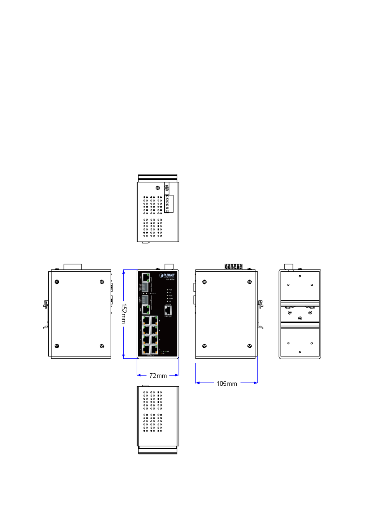
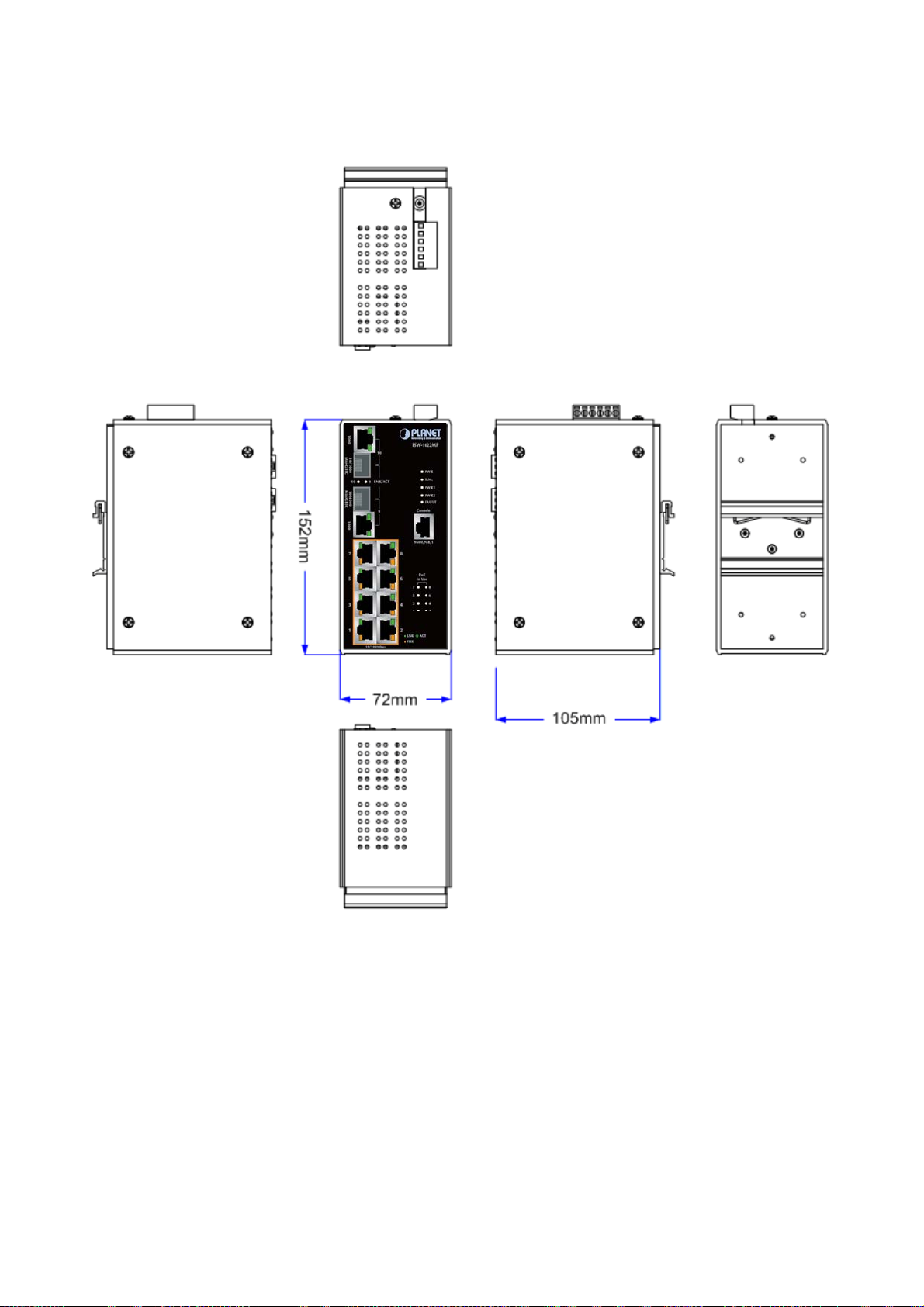
2.1.1 Physical Dimension
ISW-1022M / ISW-1022MT Managed Industrial Switch dimension (W x D x H) : 72mm x 105mm x 152mm
Figure 2-1 ISW-1022M panel layout
18
Page 19
User’s Manual of ISW-1022M Series and ISW-1033MT
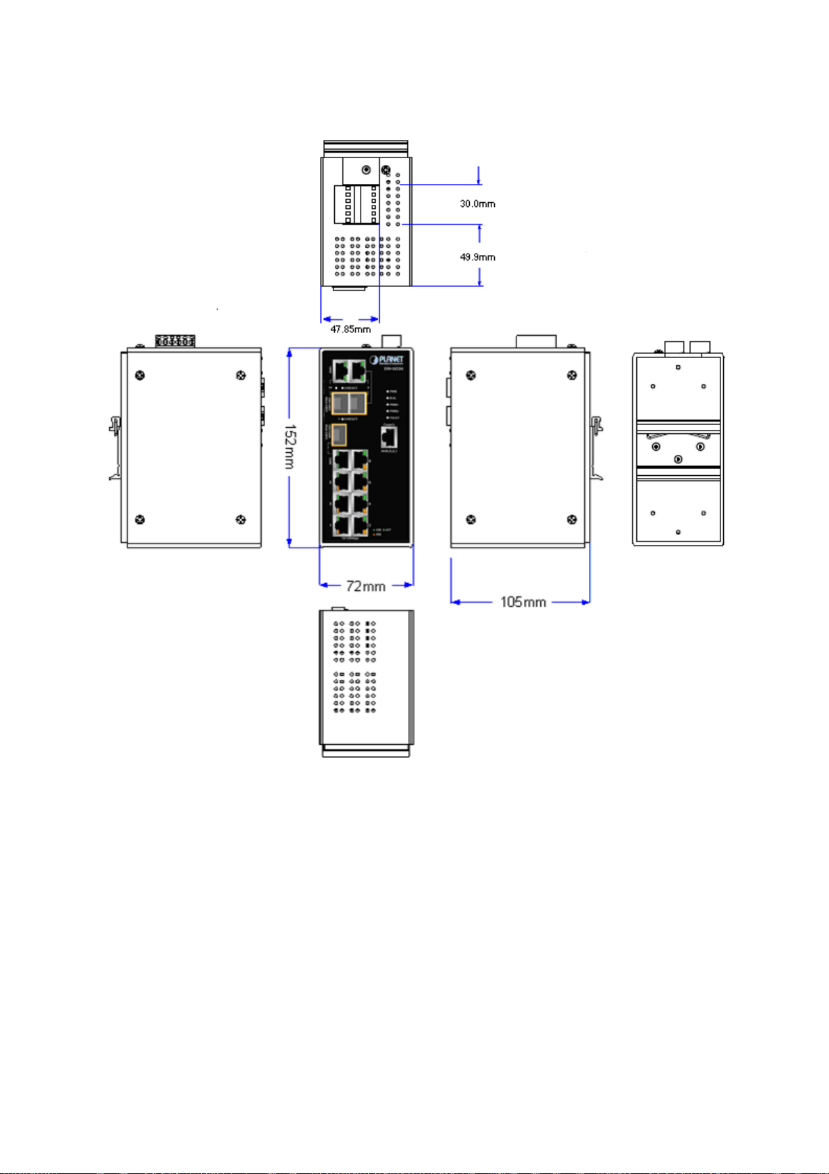
ISW-1022MPT Managed Industrial Switch dimension (W x D x H) : 72mm x 105mm x 152mm
Figure 2-2 ISW-1022MPT panel layout
19
Page 20
User’s Manual of ISW-1022M Series and ISW-1033MT
ISW-1033MT Managed Industrial Switch dimension (W x D x H) : 72mm x 105mm x 152mm
Figure 2-3 ISW-1033MT panel layout
20
Page 21
User’s Manual of ISW-1022M Series and ISW-1033MT
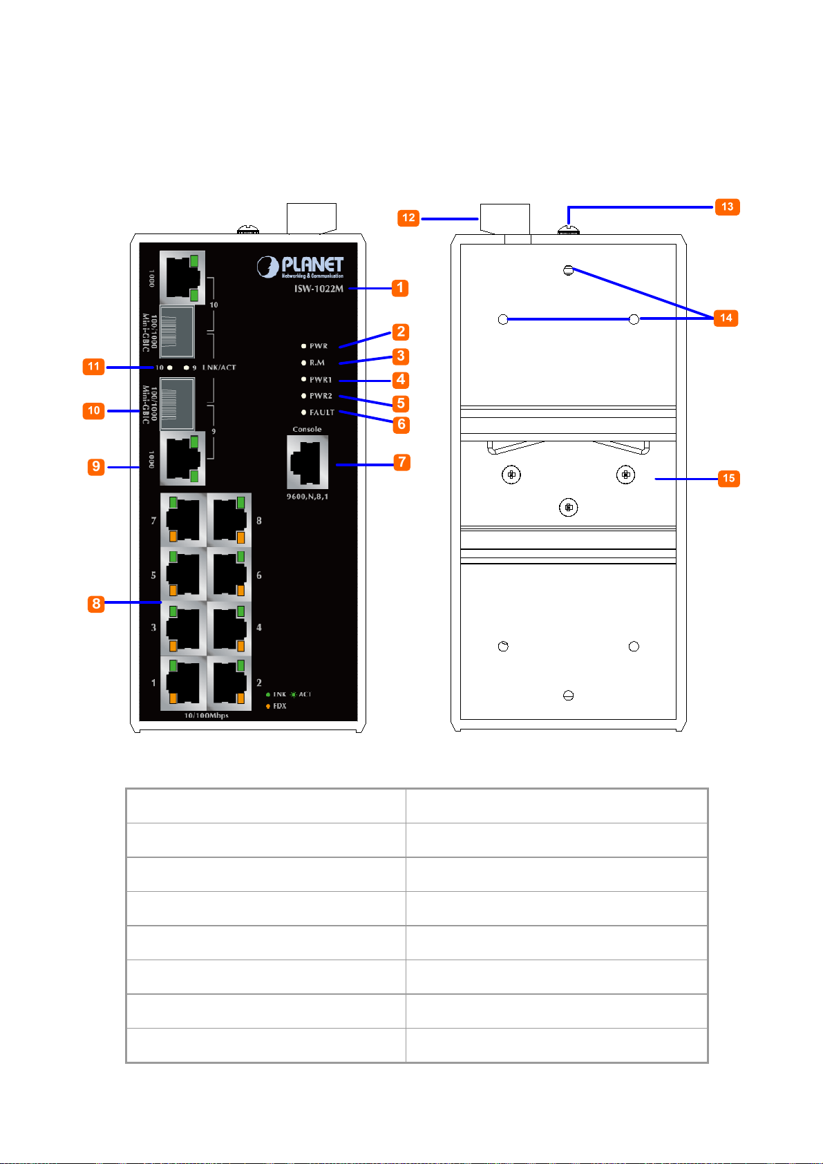
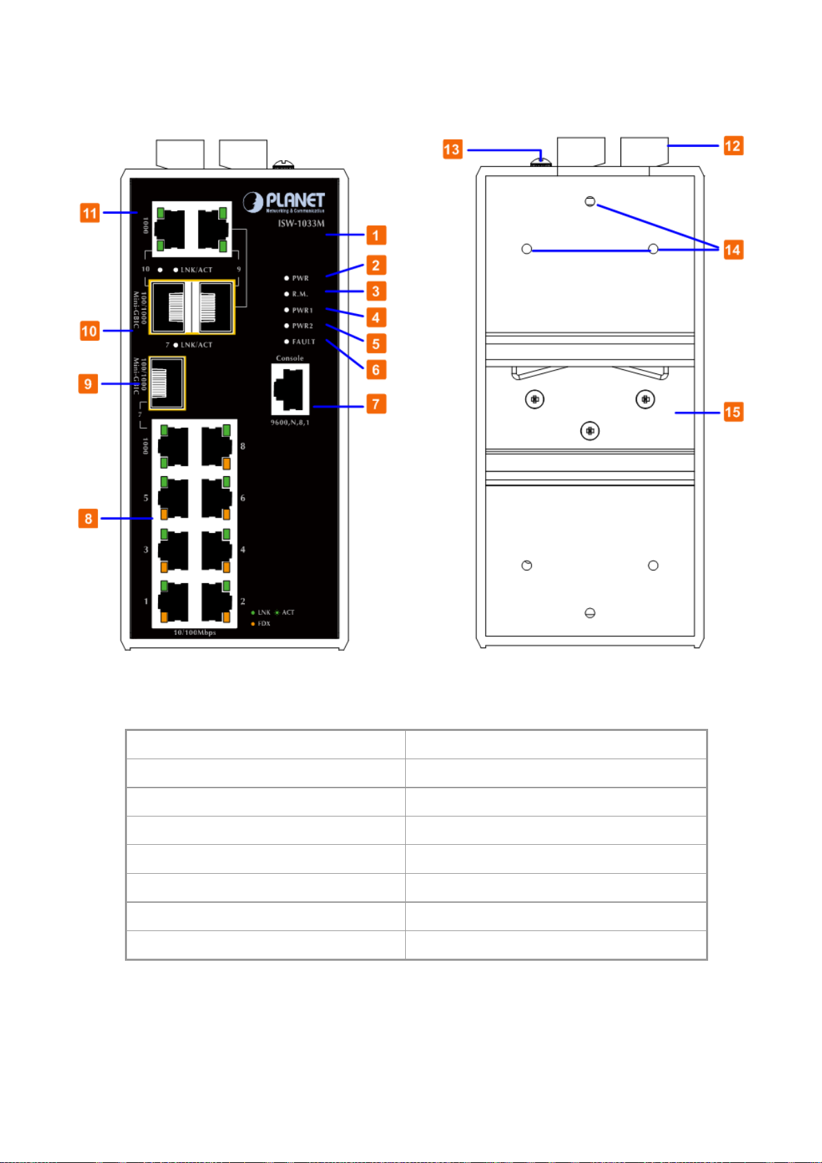
2.1.2 Front / Rear Panel
The Front Panel and Rear Panel of the ISW-1022M / ISW-1022MT Managed Industrial Switch are shown as below:
Figure 2-4 Front and Rear Panel of ISW-1022M
1. Model Name 9. 10/100/1000Base-T port
2. System Power: LED 10. 1000Base-SX/LX SFP slot
3. Ring Master: LED indicator 11. LED indicators for 1000Base-SX/LX ort
4. LED for power 1 input 12. 6-Pin Terminal Block
5. LED for power 2 input 13. Ground Screw
6. FAULT: LED indicator 14. Screw holes for Wall Mounting kit
7. RJ-45 type RS-232 Console 15. DIN-Rail Kit
8. 8 x 10/100Base-TX port
21
Page 22
User’s Manual of ISW-1022M Series and ISW-1033MT
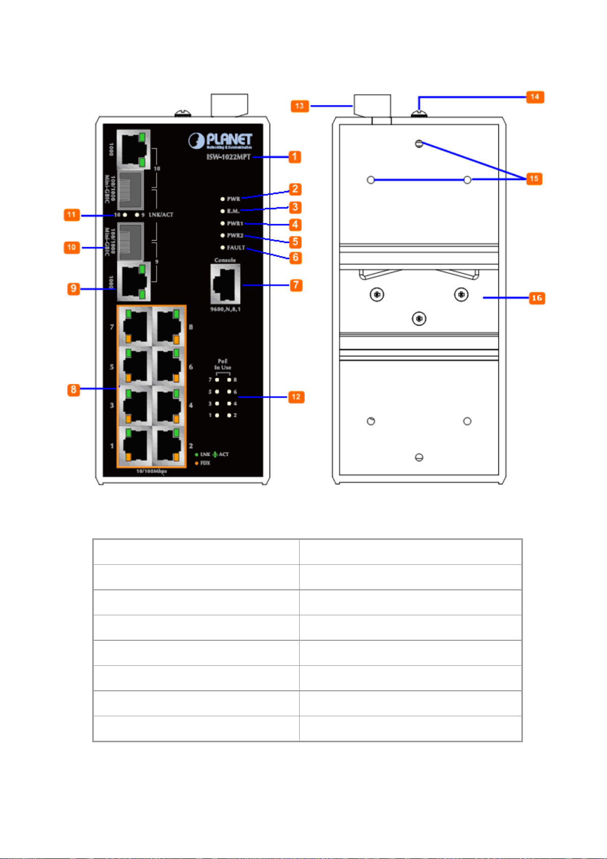
The Front Panel and Rear Panel of the ISW-1022MPT Managed Industrial Switch are shown as below:
Figure 2-5 Front and Rear Panel of ISW-1022MPT
1. Model Name 9. 10/100/1000Base-T port
2. System Power: LED 10. 1000Base-SX/LX SFP slot
3. Ring Master: LED indicator 11. LED indicators for 1000Base-SX/LX ort
4. LED for power 1 input 12. LED indicators for PoE power output
5. LED for power 2 input 13. 6-Pin Terminal Block
6. FAULT: LED indicator 14. Ground Screw
7. RJ-45 type RS-232 Console 15. Screw holes for Wall Mounting kit
8. 8 x 10/100Base-TX PoE port 16. DIN-Rail Kit
22
Page 23
User’s Manual of ISW-1022M Series and ISW-1033MT
The Front Panel and Rear Panel of the ISW1033MT Managed Industrial Switch are shown as below:
Figure 2-6 Front and Rear Panel of ISW-1033MT
1. Model Name 9. 1000Base-SX/LX SFP slot (Port-7)
2. System Power: LED 10. 1000Base-SX/LX SFP slots (Port-9 / Port-10)
3. Ring Master: LED indicator 11. 10/100/1000Base-T ports (Port-9 / Port-10)
4. LED for power 1 input 12. 6-Pin Terminal Block
5. LED for power 2 input 13. Ground Screw
6. FAULT: LED indicator 14. Screw holes for Wall Mounting kit
7. RJ-45 type RS-232 Console 15. DIN-Rail Kit
8. 8 x 10/100Base-TX port
23
Page 24
User’s Manual of ISW-1022M Series and ISW-1033MT
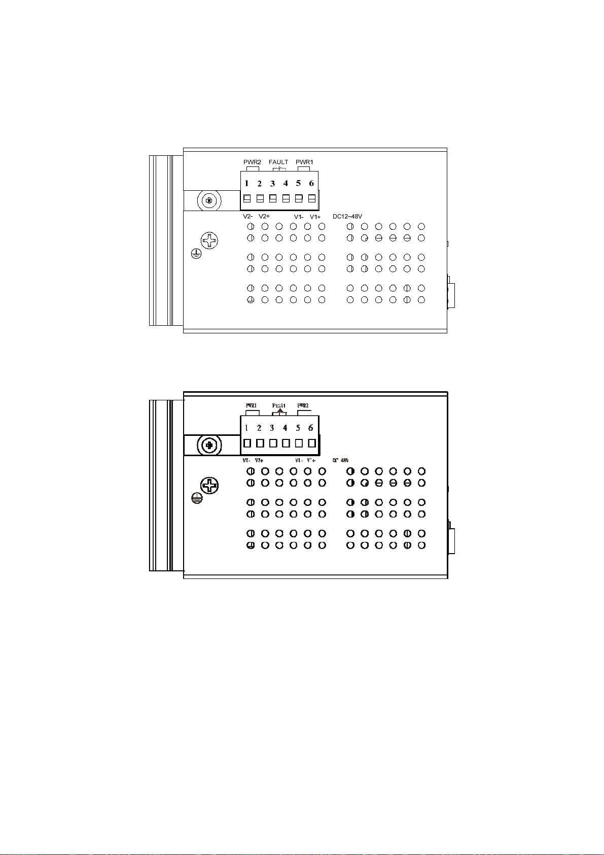
2.1.3 Top View
The top panel of the ISW-1022M series Managed Industrial Switch has one terminal block connector of two DC power
inputs and one fault alarm.
Figure 2-7 Top Panel of ISW-1022M / ISW-1022MT
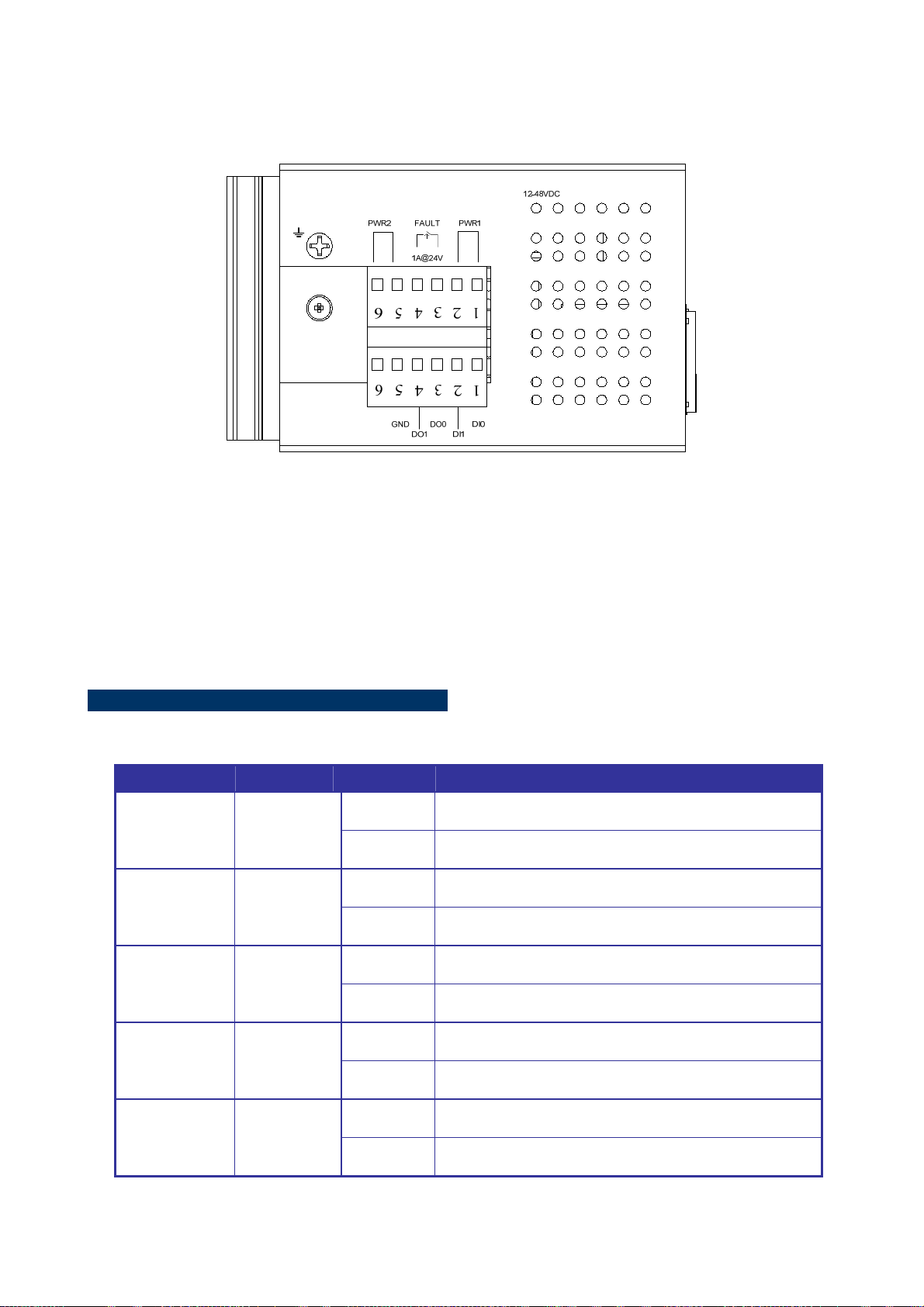
Figure 2-7 Top Panel of ISW-1022MPT
24
Page 25
User’s Manual of ISW-1022M Series and ISW-1033MT
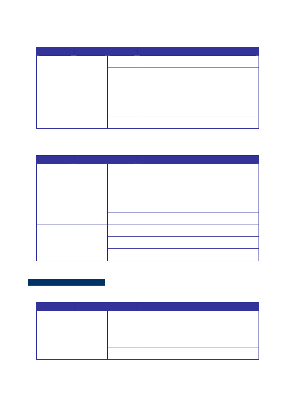
The top panel of the ISW-1033MT Managed Industrial Switch has one terminal block connector of two DC power inputs
and one fault alarm. The other one terminal block is used for DIDO.
Figure 2-7 Top Panel of ISW-1033MT
2.1.4 LED Indicators
The diagnostic LEDs that provide real-time information of system and optional status are located on the front panel of the
ISW-1022M series. The following table provides the description of the LED status and their meanings for the Managed
Industrial Switch.
ISW-1022M / ISW-1022MT LED Indicators
System
LED Color Status Meaning
On The switch unit is power on.
PWR Green
Off No power.
On The industrial switch is the master of X-Ring group.
R.M. Green
Off The industrial switch is not a ring master in X-Ring group.
On Power 1 is active.
PWR1 Green
Off Power 1 is inactive.
PWR2 Green
FAULT Red
On Power 2 is active.
Off Power 2 is inactive.
On Power or port failure.
Off No failure.
25
Page 26
User’s Manual of ISW-1022M Series and ISW-1033MT
10/100Base-TX Ports – Port-1 to Port-8
LED Color Status Meaning
On A network device is detected.
Green
Blinking
The port is transmitting or receiving packets from the TX
device.
Port-1 ~
Port-8
Amber
Off No device attached.
On The port is operating in full-duplex mode.
Blinking Collision of Packets occurs.
Off The port is in half-duplex mode or no device is attached.
10/100/1000Base-T / SFP combo interface - Port-9, Port-10
LED Color Status Meaning
Port 9, Port 10
(RJ-45)
Green
(Upper LED)
Green
(Lower LED)
On
Blinking
Off
On
Off
A network device is detected.
The port is transmitting or receiving packets from the TX
device.
No device attached
1000M
10/100M
Link/Active
(P9, P10 SFP)
Green
On
Blinking
Off
The SFP port is linking
The port is transmitting or receiving packets from the TX
device.
No device attached
ISW-1033MT LED Indicators
System
LED Color Status Meaning
On The switch unit is power on.
PWR Green
Off No power.
On The industrial switch is the master of X-Ring group.
R.M. Green
Off The industrial switch is not a ring master in X-Ring group.
26
Page 27

User’s Manual of ISW-1022M Series and ISW-1033MT
On Power 1 is active.
PWR1 Green
Off Power 1 is inactive.
On Power 2 is active.
PWR2 Green
Off Power 2 is inactive.
On Power or port failure.
FAULT Red
Off No failure.
10/100Base-TX Ports – Port-1 to Port-6 and Port-8
LED Color Status Meaning
On A network device is detected.
Green
Blinking
The port is transmitting or receiving packets from the TX
device.
Port-1 ~ 6 &
Port-8
Amber
Off No device attached.
On The port is operating in full-duplex mode.
Blinking Collision of Packets occurs.
Off The port is in half-duplex mode or no device is attached.
10/100/1000Base-T / SFP combo interface - Port-7, Port-9 and Port-10
LED Color Status Meaning
Port 7, Port 9,
Port 10
(RJ-45)
Link/Active
(P7, P9, P10
SFP)
Green
(Upper LED)
Green
(Lower LED)
Green
On
Blinking
Off
On
Off
On
Blinking
Off
A network device is detected.
The port is transmitting or receiving packets from the TX
device.
No device attached
1000M
10/100M
The SFP port is linking
The port is transmitting or receiving packets from the TX
device.
No device attached
27
Page 28

User’s Manual of ISW-1022M Series and ISW-1033MT
ISW-1022MPT LED Indicators
System
LED Color Status Meaning
On The switch unit is power on.
PWR Green
Off No power.
On The industrial switch is the master of X-Ring group.
R.M. Green
Off The industrial switch is not a ring master in X-Ring group.
On Power 1 is active.
PWR1 Green
Off Power 1 is inactive.
On Power 2 is active.
PWR2 Green
Off Power 2 is inactive.
On Power or port failure.
FAULT Red
Off No failure.
10/100Base-TX Ports – Port-1 to Port-8
LED Color Status Meaning
On A network device is detected.
The port is transmitting or receiving packets from the TX
device.
Port-1 ~
Port-8
Green
Amber
Blinking
Off No device attached.
On The port is operating in full-duplex mode.
Blinking Collision of Packets occurs.
Off The port is in half-duplex mode or no device is attached.
PoE port link – Port-1 to Port-8
LED Color Status Meaning
On
Off
An IEEE 802.3af PoE power device is detected.
No IEEE 802.3af PoE power device attached
FWD
(P1 to P8)
Green
28
Page 29

User’s Manual of ISW-1022M Series and ISW-1033MT
10/100/1000Base-T / SFP combo interface - Port-9, Port-10
LED Color Status Meaning
Port 9, Port 10
(RJ-45)
Link/Active
(P9, P10 SFP)
Green
(Upper LED)
Green
(Lower LED)
Green
On
Blinking
Off
On
Off
On
Blinking
Off
A network device is detected.
The port is transmitting or receiving packets from the TX
device.
No device attached
1000M
10/100M
The SFP port is linking
The port is transmitting or receiving packets from the TX
device.
No device attached
29
Page 30

User’s Manual of ISW-1022M Series and ISW-1033MT
2.2 Install the Switch
This section describes how to install your Managed Industrial Switch and make connections to the Managed Industrial
Switch. Please read the following topics and perform the procedures in the order being presented. To install your switch on
a desktop or shelf, simply complete the following steps.
In this paragraph, we will describe how to install the 8 10/100TX w/ Ring Managed Industrial Switch and the installation
points attended to it.
2.2.1 Installation Steps
1. Unpack the Industrial switch
2. Check if the DIN-Rail is screwed on the Industrial switch or not. If the DIN-Rail is not screwed on the Industrial
switch, please refer to DIN-Rail Mounting section for DIN-Rail installation. If users want to wall mount the Industrial
switch, please refer to Wall Mount Plate Mounting section for wall mount plate installation.
3. To hang the Industrial switch on the DIN-Rail track or wall.
4. Power on the Industrial switch. Please refer to the Wiring the Power Inputs section for knowing the information about
how to wire the power. The power LED on the Industrial switch will light up. Please refer to the LED Indicators section
for indication of LED lights.
5. Prepare the twisted-pair, straight through Category 5 cable for Ethernet connection.
6. Insert one side of RJ-45 cable (category 5 ) into the I ndus trial switch Ethernet port (RJ-45 port) and another side of
RJ-45 cable (category 5) to the network device’s Ethernet port (RJ-45 port), ex: Switch PC or Server. The UTP port
(RJ-45) LED on the Industrial switch will light up when the cable is connected with the network device. Please refer to
the LED Indicators section for LED light indication.
Make sure that the connected network devices support MDI/MDI-X. If it does not support,
use the crossover category-5 cable.
7. When all connections are set and LED lights all show in normal, the installation is complete.
30
Page 31

User’s Manual of ISW-1022M Series and ISW-1033MT
2.2.2 DIN-Rail Mounting
The DIN-Rail is screwed on the Industrial Switch when out of factory. If the DIN-Rail is not screwed on the Industrial
Switch, please see the following pictures to screw the DIN-Rail on the Switch. Follow the steps below to hang the
Industrial Switch.
Figure 2-8 Rear Panel – DIN-Rail Kit
1. First, insert the top of DIN-Rail into the track.
Figure 2-9 DIN-Rail Mounting
31
Page 32

User’s Manual of ISW-1022M Series and ISW-1033MT
2. Then, lightly push the DIN-Rail into the track.
Figure 2-10 DIN-Rail mounting
3. Check if the DIN-Rail is tightened on the track or not.
4. To remove the industrial switch from the track, reverse above steps.
2.2.3 Wall Mount Plate Mounting
Follow the steps below to mount the Industrial Switch with wall mount plate.
1. Remove the DIN-Rail from the Industrial Switch; loose the screws to remove the DIN-Rail.
2. Place the wall mount plate on the rear panel of the Industrial Switch.
3. Use the screws to screw the wall mount plate on the Industrial Switch.
4. Use the hook holes at the corners of the wall mount plate to hang the Industrial Switch on the wall.
5. To remove the wall mount plate, reverse the above steps.
Figure 2-11 Wall mounting
32
Page 33

User’s Manual of ISW-1022M Series and ISW-1033MT
2.2.4 Wiring the Power Inputs
The 6-contact terminal block connector on the top panel of ISW-1022M series is used for two DC redundant power input.
Please follow the steps below to insert the power wire.
1. Insert positive / negative DC power wires into the contacts 1 and 2 for POW ER 2, or 5 and 6 fo r POW E R 1.
Figure 2-12 Wiring the redundant power inputs
2. Tighten the wire-clamp screws for preventing the wires from loosing.
1 2 3 4 5 6
Power 2 Power 1
- + - +
Figure 2-13 6-Pin Terminal Block power wiring input
The wire gauge for the terminal block should be in the range between 12 ~ 24 AWG.
33
Page 34

User’s Manual of ISW-1022M Series and ISW-1033MT
2.2.5 Wiring the Fault Alarm Contact
The fault alarm contacts are in the middle of the terminal block connector as the picture shows below. Inserting the wires,
the Industrial Switch will detect the fault status of the power failure, or port link failure (available for managed model) and
then forms an open circuit. The following illustration shows an application example for wiring the fault alarm contacts.
The wire gauge for the terminal block should be in the range between 12 ~ 24 AWG.
Insert the wires into the fault alarm contacts
Figure 2-14 Power Fault Alarm trigger description
34
Page 35

User’s Manual of ISW-1022M Series and ISW-1033MT
2.2.6 Wiring the Digital Inputs / Outputs (ISW-1033MT)
There is another terminal block comprising two sets of digital input/output contacts on the top side of ISW-1033MT. Please
refer to chapter 5.8 for how to configure Digital Input/Output. The following illustration shows the pin assignment of the
DIDO connector. Please note do not connect DO0/DO1 to the external device using power higher than 40V/200mA.
35
Page 36

User’s Manual of ISW-1022M Series and ISW-1033MT
2.2.7 Installing the SFP transceiver
The sections describe how to insert an SFP transceiver into an SFP slot.
The SFP transceivers are hot-pluggable and hot-swappable. You can plug-in and out the transceiver to/from any SFP port
without having to power down the Industrial Switch. As the Figure 2-15 appears.
Figure 2-15 Plug-in the SFP transceiver
Approved PLANET SFP Transceivers
PLANET Industrial Switch supports both Single mode and Multi-mode SFP transceiver. The following list of approved
PLANET SFP transceivers is correct at the time of publication:
■ MGB-SX SFP (1000BASE-SX SFP transceiver / Multi-mode / 850nm / 220m~550m)
■ MGB-LX SFP (1000BASE-LX SFP transceiver / Single mode / 1310nm / 10km)
■ MGB-L30 SFP (1000BASE-LX SFP transceiver / Single mode / 1310nm / 30km)
■ MGB-L50 SFP (1000BASE-LX SFP transceiver / Single mode / 1310nm / 50km)
■ MGB-LA10 SFP (1000BASE-LX SFP transceiver / WDM Single mode / TX: 1310nm, RX: 1550nm/ 10km)
■ MGB-LB10 SFP (1000BASE-LX SFP transceiver / WDM Single mode / TX: 1550nm, RX: 1310nm / 10km)
It recommends using PLANET SFPs on the Managed Industrial Switch. If you insert a SFP
transceiver that is not supported, the Managed Industrial Switch will not recognize it.
Before connect the other switches, workstation or Media Converter.
1. Make sure both side of the SFP transceiver are with the same media type, for example: 1000Base-SX to
1000Base-SX, 1000Bas-LX to 1000Base-LX.
2. Check the fiber-optic cable type match the SFP transceiver model.
¾ To connect to 1000Base-SX SFP transceiver, use the Multi-mode fiber cable- with one side must be male
duplex LC connector type.
¾ To connect to 1000Base-LX SFP transceiver, use the Single-mode fiber cable-with one side must be male
duplex LC connector type.
36
Page 37

User’s Manual of ISW-1022M Series and ISW-1033MT
Conn ect the fiber cable
1. Attach the duplex LC connector on the network cable into the SFP transceiver.
2. Connect the other end of the cable to a device – switches with SFP installed, fiber NIC on a workstation or a Media
Converter.
3. Check the LNK/ACT LED of the SFP slot on the front of the Managed Industrial Switch. Ensure that the SFP
transceiver is operating correctly.
4. Check the Link mode of the SFP port if the link failed. Co works with some fiber-NICs or Media Converters, set the
Link mode to “1000 Force” is needed.
Figure 2-16 LC fiber optical cable connects to the transceiver
Remove the transceiver module
1. Make sure there is no network activity by consult or check with the network administrator. Or through the
management interface of the switch/converter (if available) to disable the port in advance.
2. Remove the Fiber Optic Cable gently.
Figure 2-17 Pull out the SFP transceiver
37
Page 38

3. Turn the handle of the MGB module to horizontal.
4. Pull out the module gently through the handle.
Figure 2-18 Pull out from the transceiver
User’s Manual of ISW-1022M Series and ISW-1033MT
Never pull out the module without pull the handle or the push bolts on the module. Direct pull
out the module with violent could damage the module and SFP module slot of the Managed
Industrial Switch.
38
Page 39

User’s Manual of ISW-1022M Series and ISW-1033MT
3. Network Application
This chapter provides some sample applications to help user to have more actual idea of Industrial Switch function
application. A sample application of the industrial switch is as below:
Factory Redundant Ring Application
Transportation Networking and Public Wireless Service
39
Page 40

User’s Manual of ISW-1022M Series and ISW-1033MT
3.1 Rapid Ring Application
The industrial Switch supports the Rapid Ring (X-Ring) protocol that can help the network system to recovery from
network connection failure within 20ms or less, and make the network system more reliable. The X-Ring algorithm is
similar to spanning tree protocol (STP) algorithm but its recovery time is faster than STP. The following figure is a sample
X-Ring application.
3.2 Coupling Ring Application
In the network, it may have more than one X-Ring group. By using the coupling ring function, it can connect each X-Ring
for the redundant backup. It can ensure the transmissions between two ring groups not to fail. The following figure is a
sample of coupling ring application.
40
Page 41

User’s Manual of ISW-1022M Series and ISW-1033MT
3.3 Dual Homing Application
Dual Homing function is to prevent the connection lose from between X-Ring group and upper level/core switch. Assign
two ports to be the Dual Homing port that is backup port in the X-Ring group. The Dual Homing function only works when
the X-Ring function is active. Each X-Ring group only has one Dual Homing port.
In Dual Homing application architecture, the upper level switches need to enable the Rapid
Spanning Tree protocol.
41
Page 42

User’s Manual of ISW-1022M Series and ISW-1033MT
4. Console Management
4.1 Connecting to the Console Port
The supplied cable which one end is RS-232 connector and the other end is RJ-45 connector. Attach the end of RS-232
connector to PC or terminal and the other end of RJ-45 connector to the console port of the switch. The connected
terminal or PC must support the terminal emulation program.
4.2 Pin Assignment
DB9 Pin Define for RJ-45 Connector
DB9-PIN RJ-45 Connector
1
2
3
4
5
6
7
8
9
1 Orange/White
2 Orange
3 Green/White
4 Blue
5 Blue/White
6 Green
7 Brown/White
8 Brown
42
Page 43

User’s Manual of ISW-1022M Series and ISW-1033MT
4.3 Login in the Console Interface
To configure the system, connect a serial cable to a COM port on a PC or notebook computer and to RJ-45 type serial
(console) port of the Managed Industrial Switch. The console port of the Managed Industrial Switch is DCE already, so
that you can connect the console port directly through PC without the need of Null Modem.
A terminal program is required to make the software connection to the ISW Managed Industrial Switch. Windows' Hyper
Terminal program may be a good choice. The Hyper Terminal can be accessed from the Start menu.
1. Click START, then Programs, Accessories and then Hyper Terminal.
2. When the following screen appears, make sure that the COM port should be configured as:
Baud Rate: 9600 bps
Data Bits: 8
Parity: none
Stop Bit: 1
Flow control: None
The settings of communication parameters
43
Page 44

User’s Manual of ISW-1022M Series and ISW-1033MT
Once the terminal has connected to the device, power on the ISW Managed Industrial Switch, the terminal will display that
it is running testing procedures.
Then, the following message asks the login password. The factory default password as following and the login screen in
below figure appears.
User name: admin
Password: admin
Console login interface
1. For security reason, please change and memorize the new password after this first setup.
2. Only accept command in lowercase letter under console interface.
44
Page 45

User’s Manual of ISW-1022M Series and ISW-1033MT
4.4 CLI Management
The system supports the console management—CLI command. After you log in on to the system, you will see a command
prompt. To enter CLI management interface, type in “enable” command.
CLI command interface
The following table lists the CLI commands and description.
45
Page 46

User’s Manual of ISW-1022M Series and ISW-1033MT
4.5 Commands Level
Modes Access Method Prompt Exit Method About This Mode1
The user commands available
at the user level are a subset of
User EXEC
Privileged
EXEC
Global
Configuration
VLAN database
Begin a session
with your switch.
Enter the enable
command while in
User EXEC mode.
Enter the configure
command while in
privileged EXEC
mode.
Enter the vlan
database command
while in privileged
EXEC mode.
switch>
switch#
switch (config)#
switch (vlan)#
Enter logout or
quit.
Enter disable to
exit.
To exit to
privileged EXEC
mode, enter exit
or end
To exit to user
EXEC mode,
enter exit.
those available at the
privileged level.
Use this mode to:
• Perform basic tests.
• Display system information.
The privileged command is the
advanced mode.
Use this mode to
• Display advanced function
status
• Save configuration
Use this mode to configure
those parameters that are
going to be applied to your
switch.
Use this mode to configure
VLAN-specific parameters.
Interface
configuration
Enter the interface
of fast Ethernet
command (with a
specific interface)
while in global
configuration mode.
switch
(config-if)#
To exit to global
configuration
mode, enter exit.
To exit to
privileged EXEC
mode, enter exit
or end.
Use this mode to configure
parameters for the switch and
Ethernet ports.
46
Page 47

User’s Manual of ISW-1022M Series and ISW-1033MT
5. Web-Based Management
This section introduces the configuration and functions of the Web-Based management.
5.1 About Web-based Management
The Managed Industrial Switch offers management features that allow users to manage the Managed Industrial Switch
from anywhere on the network through a standard browser such as Microsoft Internet Explorer.
The Web-Based Management supports Internet Explorer 6.0. It is based on Java Applets with an aim to reduce network
bandwidth consumption, enhance access speed and present an easy viewing screen.
By default, IE6.0 or later version does not allow Java Applets to open sockets. The user has to
explicitly modify the browser setting to enable Java Applets to use network ports.
The following screen based on ISW-1022M. For ISW-1022M series and ISW-1033MT, the WEB
UI display will be the same as ISW-1022M. The PoE function and Digital Inputs / Outputs function
will be described additional.
The Managed Industrial Switch can be configured through an Ethernet connection, make sure the manager PC must be
set on same the IP subnet address with the Managed Industrial Switch.
For example, the default IP address of the Managed Industrial Switch is 192.168.0.100, then the manager PC should be
set at 192.168.0.x (where x is a number between 1 and 254, except 100), and the default subnet mask is 255.255.255.0.
If you have changed the default IP address of the Managed Industrial Switch to 192.168.1.1 with subnet mask
255.255.255.0 via console, then the manager PC should be set at 192.168.1.x (where x is a number between 2 and 254)
to do the relative configuration on manager PC.
47
Page 48

User’s Manual of ISW-1022M Series and ISW-1033MT
5.2 Requirements
• Workstations of subscribers running Windows 98/ME, NT4.0, 2000/2003/XP, MAC OS9 or later, Linux, UNIX or other
platform compatible with TCP/IP protocols.
• Workstation installed with Ethernet NIC (Network Card)
• Ethernet Port connect
¾ Network cables - Use standard network (UTP) cables with RJ45 connectors.
¾ Above PC installed with WEB Browser and JAVA runtime environment Plug-in
It is recommended to use Internet Explore 6.0 or above to access ISW-1022M series and
ISW-1033MT Managed Industrial Switch.
5.3 Logging on the switch
1. Use Internet Explorer 6.0 or above Web browser. Enter the factory-default IP address to access the Web interface.
The factory-default IP Address as following:
http://192.168.0.100
2. When the following login screen appears, please enter the default username "admin" with password “admin” (or
the username/password you have changed via console) to login the main screen of Managed Industrial Switch. The
login screen in Figure 5-1 appears.
Figure 5-1 Login screen
48
Page 49

User’s Manual of ISW-1022M Series and ISW-1033MT
Default User name: admin
Default Password: admin
3. After entering the username and password, the main screen appears as Figure 5-2.
Figure 5-2 Default main page
4. The Switch Menu on the left of the Web page let you access all the commands and statistics the Switch provides.
Now, you can use the Web management interface to continue the switch management or manage the Managed Industrial
Switch by Web interface. The Switch Menu on the left of the web page let you access all the commands and statistics the
Managed Industrial Switch provides.
1. It is recommended to use Internet Explore 6.0 or above to access Managed Industrial
Switch.
2. The changed IP address take effect immediately after click on the Save button, you need to
use the new IP address to access the Web interface.
3. For security reason, please change and memorize the new password after this first setup.
4. Only accept command in lowercase letter under web interface.
49
Page 50

User’s Manual of ISW-1022M Series and ISW-1033MT
5.4 System
Use the System menu items to display and configure basic administrative details of the Managed Industrial Switch. Under
System the following topics are provided to configure and view the system information: This section has the following
items:
■ System Information Provides basic system description, including contact information
■ IP Configuration Sets the IP address for management access
■ DHCP Server Configure the Switch as a DHCP server for assigning dynamic IP addresses
to devices on a network.
■ TFTP Upgrade the firmware via TFTP server
Save/view the switch configuration to remote host
Upload the switch configuration from remote host
■ Fault Relay Alarm Provides relay output for port breakdown, power fail
■ SNTP Configuration Simple Network Time Protocol. Configures SNTP client settings, including
broadcast mode or a specified list of servers
■ IP Security Supports 10 IP addresses that have permission to access the switch
management and to prevent unauthorized intruder.
■ User Authentication
■ Factory Default
■ System Reboot Restarts the switch
Allows configuring the system user name and password required to access
the web pages or log in from CLI.
Reset the configuration of the Managed Industrial Switch
50
Page 51

User’s Manual of ISW-1022M Series and ISW-1033MT
5.4.1 System Information
User can assign the system name, description, location and contact personnel to identify the switch. The version table
below is a read-only field to show the basic information of the switch.
The page includes the following fields:
Object Description
System Name:
System Description:
System Location:
System Contact:
Firmware Version:
Kernel Version:
MAC Address:
Figure 5-3 Switch settings interface
Assign the system name of the switch (The maximum length is 64 bytes)
Describes the switch
Assign the switch physical location (The maximum length is 64 bytes).
Enter the name of contact person or organization.
Displays the switch’s firmware version
Displays the kernel software version
Displays the unique hardware address assigned by manufacturer (default)
51
Page 52

User’s Manual of ISW-1022M Series and ISW-1033MT
5.4.2 IP Configuration
The switch is a network device which needs to be assigned an IP address for being identified on the network. Users have
to decide a means of assigning IP address to the switch.
The page includes the following fields:
Object Description
DHCP Client:
IP Address:
Figure 5-4 IP configuration interface
Enable or disable the DHCP client function. When DHCP client function is
enabled, the switch will be assigned an IP address from the network DHCP
server. The default IP address will be replaced by the assigned IP address on
DHCP server. After the user clicks Apply, a popup dialog shows up to inform the
user that when the DHCP client is enabled, the current IP will lose and user
should find the new IP on the DHCP server.
Assign the IP address that the network is using. If DHCP client function is
enabled, this switch is configured as a DHCP client. The network DHCP server
will assign the IP address to the switch and display it in this column.
The default IP is 192.168.0.100 or the user has to assign an IP address
manually when DHCP Client is disabled.
Subnet Mask:
Gateway:
Assign the subnet mask to the IP address. If DHCP client function is disabled,
the user has to assign the subnet mask in this column field.
Assign the network gateway for the switch. If DHCP client function is disabled,
the user has to assign the gateway in this column field.
The default gateway is 192.168.0.1.
52
Page 53

User’s Manual of ISW-1022M Series and ISW-1033MT
DNS1:
DNS2:
Assign the primary DNS IP address.
Assign the secondary DNS IP address.
5.4.3 DHCP Server
DHCP is the abbreviation of Dynamic Host Configuration Protocol that is a protocol for assigning dynamic IP
addresses to devices on a network. With dynamic addressing, a device can have a different IP address every time it
connects to the network. In some systems, the device's IP address can even change while it is still connected. DHCP also
supports a mix of static and dynamic IP addresses. Dynamic addressing simplifies network administration because the
software keeps track of IP addresses rather than requiring an administrator to manage the task. This means that a new
computer can be added to a network without the hassle of manually assigning it a unique IP address.
The system provides the DHCP server function. Having enabled the DHCP server function, the switch system will be
configured as a DHCP server.
5.4.3.1 System configuration
The Dynamic Host Configuration Protocol (DHCP) Server gives out IP addresses when a device is booting up and request
an IP to logged on to the network. It must be set as a DHCP client to obtain the IP address automatically.
Figure 5-5 DHCP Server Configuration interface
The page includes the following fields:
Object Description
Enable or Disable the DHCP Server function. Enable—the switch will be the
DHCP Server:
DHCP server on your local network.
53
Page 54
User’s Manual of ISW-1022M Series and ISW-1033MT
Type in an IP address. Low IP address is the beginning of the dynamic IP range.
Low IP Address :
High IP Address:
Subnet Mask:
Gateway:
DNS:
Lease Time (sec):
5.4.3.2 Client Entries
For example, dynamic IP is in the range between 192.168.0.101 ~
192.168.0.200. In contrast, 192.168.0.101 is the Low IP address.
Type in an IP address. High IP address is the end of the dynamic IP range. For
example, dynamic IP is in the range between 192.168.0.101 ~ 192.168.0.200. In
contrast, 192.168.0.200 is the High IP address.
Type in the subnet mask of the IP configuration.
Type in the IP address of the gateway in your network.
Type in the Domain Name Server IP Address in your network.
It is the time period that system will reset the dynamic IP assignment to ensure
the dynamic IP will not been occupied for a long time or the server doesn’t know
that the dynamic IP is idle.
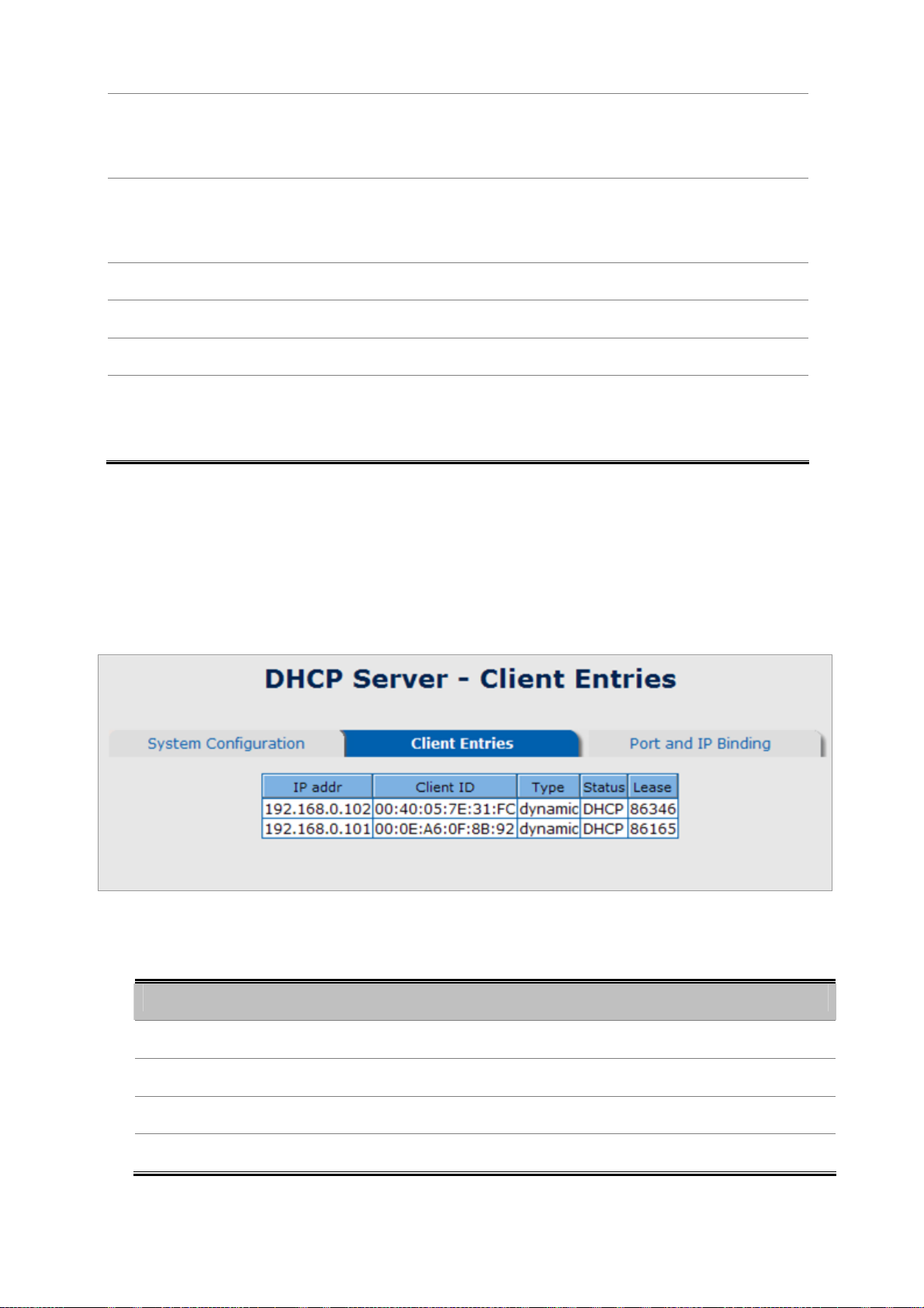
When the DHCP server function is enabled, the system will collect the DHCP client information including the assigned IP
address, the MAC address of the client device, the IP assigning type, status and lease time.
Figure 5-6 DHCP Client Entries interface
The page includes the following fields:
Object Description
• IP Addr
Specifies the Client's IP Address.
• Client ID
• Type
• Lease
Specifies the Client's Hardware Address.
Specifies the Type of Binding: Dynamic / Manual.
Specifies the Lease time left in seconds.
54
Page 55

User’s Manual of ISW-1022M Series and ISW-1033MT
5.4.3.3 Port and IP Bindings
Assign the dynamic IP address bound with the port to the connected client. The user is allowed to fill each port column
with one particular IP address. When the device is connecting to the port and asks for IP assigning, the system will assign
the IP address bound with the port.
Figure 5-7 Port and IP Bindings interface
55
Page 56

User’s Manual of ISW-1022M Series and ISW-1033MT
5.4.4 TFTP
It provides the functions allowing the user to update the switch firmware via the Trivial File Transfer Protocol (TFTP)
server. Before updating, make sure the TFTP server is ready and the firmware image is located on the TFTP server.
5.4.4.1 Update Firmware
Use this menu to download a file from specified TFTP server to the Managed Industrial Switch.
Figure 5-8 Update Firmware interface
The page includes the following fields:
Object Description
TFTP Server IP Address: Type in your TFTP server IP.
Firmware File Name: Type in the name of the firmware image file to be updated.
5.4.4.2 Restore Configuration
You can restore a previous backup configuration from the TFTP server to recover the settings. Before doing that, you must
locate the image file on the TFTP server first and the Managed Industrial Switch will download back the flash image.
Figure 5-9 Restore Configuration interface
56
Page 57

The page includes the following fields:
Object Description
User’s Manual of ISW-1022M Series and ISW-1033MT
TFTP Server IP Address:
Restore File Name:
Type in the TFTP server IP.
Type in the correct file name for restoring.
5.4.4.3 Backup Configuration
You can back up the current configuration from flash ROM to the TFTP server for the purpose of recovering the
configuration later. It helps you to avoid wasting time on configuring the settings by backing up the configuration.
The page includes the following fields:
Object Description
TFTP Server IP Address:
Backup File Name:
Type in the TFTP server IP.
Type in the file name.
Figure 5-10 Backup Configuration interface
57
Page 58

User’s Manual of ISW-1022M Series and ISW-1033MT
5.4.5 System Event Log
This page allows the user to decide whether to send the system event log, and select the mode which the system event
log will be sent to client only, server only, or both client and server. What kind of event log will be issued to the
client/server depends on the selection on the Event Configuration tab. There are five types of event available to be
issued as the event log.
Device Cold Start
Device Warm Start
Authentication Failure
X-Ring Topology Change
Port Event
5.4.5.1 Syslog Configuration
The System Logs enable viewing device events in real time, and recording the events for later usage. System Logs record
and manage events and report errors or informational messages
Figure 5-11 Syslog Configuration interface
58
Page 59

User’s Manual of ISW-1022M Series and ISW-1033MT
The page includes the following fields:
Object Description
Select the system log mode—Client Only, Server Only, or Both.
Client Only: the system event log will only be sent to this interface of the
switch
Syslog Client Mode:
System Log Server IP
Address:
Server Only: the system log will only be sent to the remote system log
server with its IP assigned.
Both: the system event log will be sent to the remote server and this
interface.
When the ‘Syslog Mode’ item is set as Server Only/Both, the user has to assign
the system log server IP address to which the log will be sent.
5.4.5.2 System Event Log—SMTP Configuration
Simple Mail Transfer Protocol (SMTP)
the SMTP server IP, mail subject, sender, mail account, password, and the recipient email addresses which the e-mail
alert will send to. There are also five types of event—
X-Ring Topology Change
the authentication mechanism including an authentication step through which the client effectively logs in to the SMTP
server during the process of sending e-mail alert.
, and
is the standard for email transmissions across the network. You can configure
Device Cold Start, Device Warm Start, Authentication Failure
Port Event
—available to be issued as the e-mail alert. Besides, this function provides
,
Figure 5-12 SMTP Configuration interface
59
Page 60

The page includes the following fields:
Object Description
User’s Manual of ISW-1022M Series and ISW-1033MT
Email Alert:
SMTP Server IP:
Sender:
Authentication:
Mail Account:
Password: Type in the password for the email account.
Confirm Password: Reconfirm the password.
Rcpt e-mail Address 1 ~
6:
With this function being enabled, the user is allowed to configure the detail
settings for sending the e-mail alert to the SMTP server when the events occur.
Assign the mail server IP address (when Email Alert is enabled, this function will
then be available).
Type in an alias of the switch in complete email address format, e.g., to identify
where the e-mail alert comes from.
Having ticked this checkbox, the mail account, password and confirm password
column fields will then show up. Configure the email account and password for
authentication when this switch logs in to the SMTP server.
Set up the email account, e.g. jack, to receive the email alert. It must be an
existing email account on the mail server.
You can also fill each of the column fields with up to 6 e-mail accounts to receive
the email alert.
60
Page 61

User’s Manual of ISW-1022M Series and ISW-1033MT
5.4.5.3 System Event Log—Event Configuration
Having ticked the
server respectively. Also, Port event log/alert (link up, link down, and both) can be sent to the system log server/SMTP
server respectively by setting the trigger condition.
Syslog/SMTP
checkboxes, the event log/email alert will be sent to the system log server and the SMTP
The page includes the following fields:
Object Description
System event selection:
Figure 5-13 Event Configuration interface
There are 4 event types—Device Cold Start, Device Warm Start, Authentication
Failure, and X-ring Topology Change. The checkboxes are not available for
ticking unless the Syslog Client Mode on the Syslog Configuration tab and the
E-mail Alert on the SMTP Configuration tab are enabled first.
Device cold start: When the device executes cold start action, the system
will issue the event log/email alert to the system log/SMTP server
respectively.
61
Page 62

Port event selection:
User’s Manual of ISW-1022M Series and ISW-1033MT
Device warm start: When the device executes warm start, the system will
issue the event log/email alert to the system log/SMTP server respectively.
Authentication Failure: When the SNMP authentication fails, the system will
issue the event log/email alert to the system log/SMTP server respectively.
X-ring topology change: When the X-ring topology has changed, the
system will issue the event log/email alert to the system log/SMTP server
respectively.
Also, before the drop-down menu items are available, the Syslog Client Mode
selection item on the Syslog Configuration tab and the E-mail Alert selection
item on the SMTP Configuration tab must be enabled first. Those drop-down
menu items have 3 selections—Link UP, Link Down, and Link UP & Link
Down. Disable means no event will be sent to the system log/SMTP server.
Link UP: The system will only issue a log message when the link-up event of
the port occurs.
Link Down: The system will only issue a log message when the link-down
event of port occurs.
Link UP & Link Down: The system will issue a log message at the time
when port connection is link-up and link-down.
5.4.6 Fault Relay Alarm
The Fault Relay Alarm function provides the Power Failure and Port Link Down/Broken detection. With both power input 1
and power input 2 installed and the check boxes of power 1/power 2 ticked, the FAULT LED indicator will then be possible
to light up when any one of the power failures occurs. As for the Port Link Down/Broken detection, the FAULT LED
indicator will light up when the port failure occurs; certainly the check box beside the port must be ticked first. Please refer
to the segment of ‘
Wiring the Fault Alarm Contact
’ for the failure detection.
Figure 5-14 Fault Relay Alarm interface
62
Page 63

The page includes the following fields:
Object Description
User’s Manual of ISW-1022M Series and ISW-1033MT
Power Failure:
Port Link Down/Broken:
Tick the check box to enable the function of lighting up the FAULT LED on the
panel when power fails.
Tick the check box to enable the function of lighting up FAULT LED on the panel
when Ports’ states are link down or broken.
5.4.7 SNTP Configuration
SNTP (Simple Network Time Protocol) is a simplified version of NTP which is an Internet protocol used to synchronize
the clocks of computers to some time reference. Because time usually just advances, the time on different node stations
will be different. With the communicating programs running on those devices, it would cause time to jump forward and
back, a non-desirable effect. Therefore, the switch provides comprehensive mechanisms to access national time and
frequency dissemination services, organize the time-synchronization subnet and the local clock in each participating
subnet peer.
Daylight saving time (DST) is the convention of advancing clocks so that afternoons have more daylight and mornings
have less. Typically clocks are adjusted forward one hour near the start of spring and are adjusted backward in autumn.
Figure 5-15 SNTP Configuration interface
The page includes the following fields:
Object Description
SNTP Client: Enable/disable SNTP function to get the time from the SNTP server.
63
Page 64

Daylight Saving Time:
User’s Manual of ISW-1022M Series and ISW-1033MT
This is used as a control switch to enable/disable daylight saving period and
daylight saving offset. Users can configure Daylight Saving Period and Daylight
Saving Offset in a certain period time and offset time while there is no need to
enable daylight saving function. Afterwards, users can just set this item as enable
without assign Daylight Saving Period and Daylight Saving Offset again.
UTC Timezone:
SNTP Sever URL:
Switch Timer:
Daylight Saving Period:
Daylight Saving Offset
(mins):
Universal Time, Coordinated. Set the switch location time zone. The following
table lists the different location time zone for your reference.
Set the SNTP server IP address. You can assign a local network time server IP
address or an internet time server IP address.
When the switch has successfully connected to the SNTP server whose IP
address was assigned in the column field of SNTP Server URL, the current
coordinated time is displayed here.
Set up the Daylight Saving beginning date/time and Daylight Saving ending
date/time. Please key in the value in the format of ‘YYYYMMDD’ and ‘HH:MM’
(leave a space between ‘YYYYMMDD’ and ‘HH:MM’).
YYYYMMDD: an eight-digit year/month/day specification.
HH:MM: a five-digit (including a colon mark) hour/minute specification.
For example, key in ‘20070701 02:00’ and ‘20071104 02:04’ in the two column
fields respectively to represent that DST begins at 2:00 a.m. on March 11, 2007
and ends at 2:00 a.m. on November 4, 2007.
For non-US and European countries, specify the amount of time for day light
savings. Please key in the valid figure in the range of minute between 0 and 720,
which means you can set the offset up to 12 hours.
Local Time Zone Conversion from UTC Time at 12:00 UTC
November Time Zone - 1 hour 11am
Oscar Time Zone -2 hours 10 am
ADT - Atlantic Daylight -3 hours 9 am
AST - Atlantic Standard
EDT - Eastern Daylight
EST - Eastern Standard
CDT - Central Daylight
CST - Central Standard
MDT - Mountain Daylight
MST - Mountain Standard
PDT - Pacific Daylight
PST - Pacific Standard
ADT - Alaskan Daylight
-4 hours 8 am
-5 hours 7 am
-6 hours 6 am
-7 hours 5 am
-8 hours 4 am
64
Page 65

User’s Manual of ISW-1022M Series and ISW-1033MT
ALA - Alaskan Standard -9 hours 3 am
HAW - Hawaiian Standard -10 hours 2 am
Nome, Alaska -11 hours 1 am
CET - Central European
FWT - French Winter
MET - Middle European
MEWT - Middle European Winter
SWT - Swedish Winter
EET - Eastern European, USSR Zone 1 +2 hours 2 pm
BT - Baghdad, USSR Zone 2 +3 hours 3 pm
ZP4 - USSR Zone 3 +4 hours 4 pm
ZP5 - USSR Zone 4 +5 hours 5 pm
+1 hour 1 pm
ZP6 - USSR Zone 5 +6 hours 6 pm
WAST - West Australian Standard +7 hours 7 pm
CCT - China Coast, USSR Zone 7 +8 hours 8 pm
JST - Japan Standard, USSR Zone 8 +9 hours 9 pm
EAST - East Australian Standard GST
Guam Standard, USSR Zone 9
IDLE - International Date Line
NZST - New Zealand Standard
NZT - New Zealand
+10 hours 10 pm
+12 hours Midnight
65
Page 66

User’s Manual of ISW-1022M Series and ISW-1033MT
5.4.8 IP Security
IP security function allows the user to assign 10 specific IP addresses that have permission to manage the switch through
the http and telnet services for the securing switch management. The purpose of giving the limited IP addresses
permission is to allow only the authorized personnel/device can do the management task on the switch.
The page includes the following fields:
Object Description
Having set this selection item in the Enable mode, the Enable HTTP Server,
IP Security Mode:
Enable HTTP Server:
Enable Telnet Server:
Security IP 1 ~ 10:
Enable Telnet Server checkboxes and the ten security IP column fields will then
be available. If not, those items will appear in grey.
Having ticked this checkbox, the devices whose IP addresses match any one of
the ten IP addresses in the Security IP1 ~ IP10 table will be given the permission
to access this switch via HTTP service.
Having ticked this checkbox, the devices whose IP addresses match any one of
the ten IP addresses in the Security IP1 ~ IP10 table will be given the permission
to access this switch via telnet service.
The system allows the user to assign up to 10 specific IP addresses for access
security. Only these 10 IP addresses can access and manage the switch through
the HTTP/Telnet service once IP Security Mode is enabled.
Figure 5-16 IP Security interface
66
Page 67

User’s Manual of ISW-1022M Series and ISW-1033MT
Remember to execute the “Save Configuration” action, otherwise the new configuration
will lose when the switch powers off.
5.4.9 User Authentication
Change web management login user name and password for the management security issue.
The page includes the following fields:
Object Description
User name:
Password:
Confirm password:
Figure 5-17 User Authentication interface
Type in the new user name
The default user name is ‘admin’
Type in the new password
The default is ‘admin’
Re-type the new password
67
Page 68
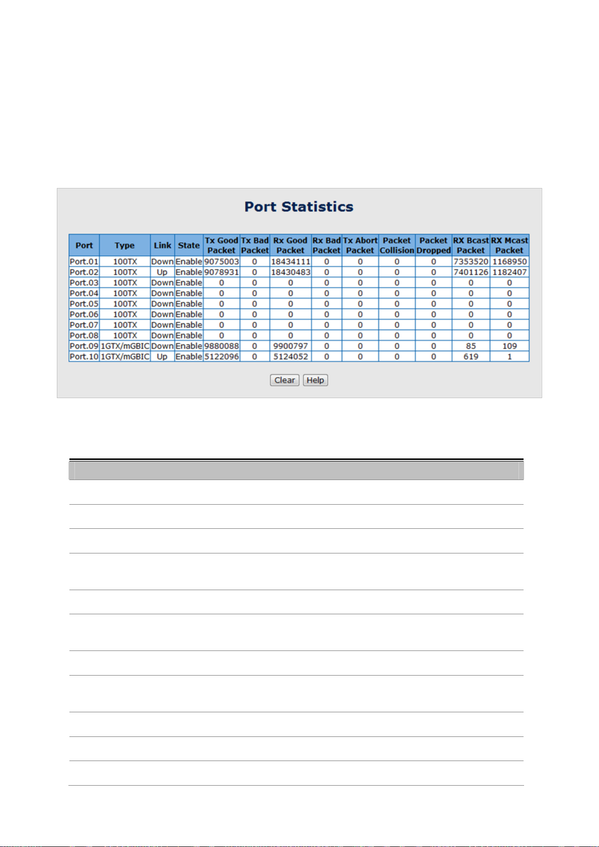
User’s Manual of ISW-1022M Series and ISW-1033MT
5.5 Port Management
5.5.1 Port Statistics
The following chart provides the current statistic information which displays the real-time packet transfer status for each
port. The user might use the information to plan and implement the network, or check and find the problem when the
collision or heavy traffic occurs.
Figure 5-18 Port Statistics interface
The page includes the following fields:
Object Description
Port:
Type:
Link: The status of linking—‘Up’ or ‘Down’.
State:
Tx Good Packet:
Tx Bad Packet:
Rx Good Packet:
Rx Bad Packet:
The port number.
Displays the current speed of connection to the port.
It’s set by Port Control. When the state is disabled, the port will not transmit or
receive any packet.
The counts of transmitting good packets via this port.
The counts of transmitting bad packets (including undersize [less than 64 octets],
oversize, CRC Align errors, fragments and jabbers packets) via this port.
The counts of receiving good packets via this port.
The counts of receiving good packets (including undersize [less than 64 octets],
oversize, CRC error, fragments and jabbers) via this port.
Tx Abort Packet:
Packet Collision:
Packet Dropped:
The aborted packet while transmitting.
The counts of collision packet.
The counts of dropped packet.
68
Page 69

User’s Manual of ISW-1022M Series and ISW-1033MT
Rx Bcast Packet:
Rx Mcast Packet:
The counts of broadcast packet.
The counts of multicast packet.
5.5.2 Port Control
In Port control you can configure the settings of each port to control the connection parameters, and the status of each
port is listed beneath.
The page includes the following fields:
Object Description
Port:
State:
Negotiation:
Figure 5-19 Port Control interface
Use the scroll bar and click on the port number to choose the port to be
configured.
Current port state. The port can be set to disable or enable mode. If the port state
is set as ‘Disable’, it will not receive or transmit any packet.
Auto and Force. Being set as Auto, the speed and duplex mode are negotiated
automatically. When you set it as Force, you have to set the speed and duplex
mode manually.
69
Page 70

User’s Manual of ISW-1022M Series and ISW-1033MT
Speed:
Duplex:
Flow Control:
Security:
5.5.3 Port Trunk
It is available for selecting when the Negotiation column is set as Force. When
the Negotiation column is set as Auto, this column is read-only.
It is available for selecting when the Negotiation column is set as Force. When
the Negotiation column is set as Auto, this column is read-only.
Whether or not the receiving node sends feedback to the sending node is
determined by this item. When enabled, once the device exceeds the input data
rate of another device, the receiving device will send a PAUSE frame which halts
the transmission of the sender for a specified period of time. When disabled, the
receiving device will drop the packet if too much to process.
When the Security selection is set as ‘On’, any access from the device which
connects to this port will be blocked unless the MAC address of the device is
included in the static MAC address table. See the segment of MAC Address
Table—Static MAC Addresses.
Port trunking is the combination of several ports or network cables to expand the connection speed beyond the limits of
any one single port or network cable. Link Aggregation Control Protocol (LACP), which is a protocol running on layer 2,
provides a standardized means in accordance with IEEE 802.3ad to bundle several physical ports together to form a
single logical channel. All the ports within the logical channel or so-called logical aggregator work at the same connection
speed and LACP operation requires full-duplex mode.
70
Page 71

User’s Manual of ISW-1022M Series and ISW-1033MT
5.5.3.1 Aggregator setting
This section provides Port Trunk-Aggregator Setting of each port from the Switch, the screen in Figure 5-20 appears.
Figure 5-20 Port Trunk—Aggregator Setting interface (two ports are added to the left field with LACP
enabled)
The page includes the following fields:
Object Description
A value which is used to identify the active LACP. The Managed Industrial
System Priority:
Group ID:
LACP:
Switch with the lowest value has the highest priority and is selected as the active
LACP peer of the trunk group.
There are 13 trunk groups to be selected. Assign the "Group ID" to the trunk
group.
When enabled, the trunk group is using LACP. A port which joins an LACP trunk
group has to make an agreement with its member ports first. Please notice that a
trunk group, including member ports split between two switches, has to enable
the LACP function of the two switches. When disabled, the trunk group is a static
trunk group. The advantage of having the LACP disabled is that a port joins the
trunk group without any handshaking with its member ports; but member ports
won’t know that they should be aggregated together to form a logic trunk group.
71
Page 72
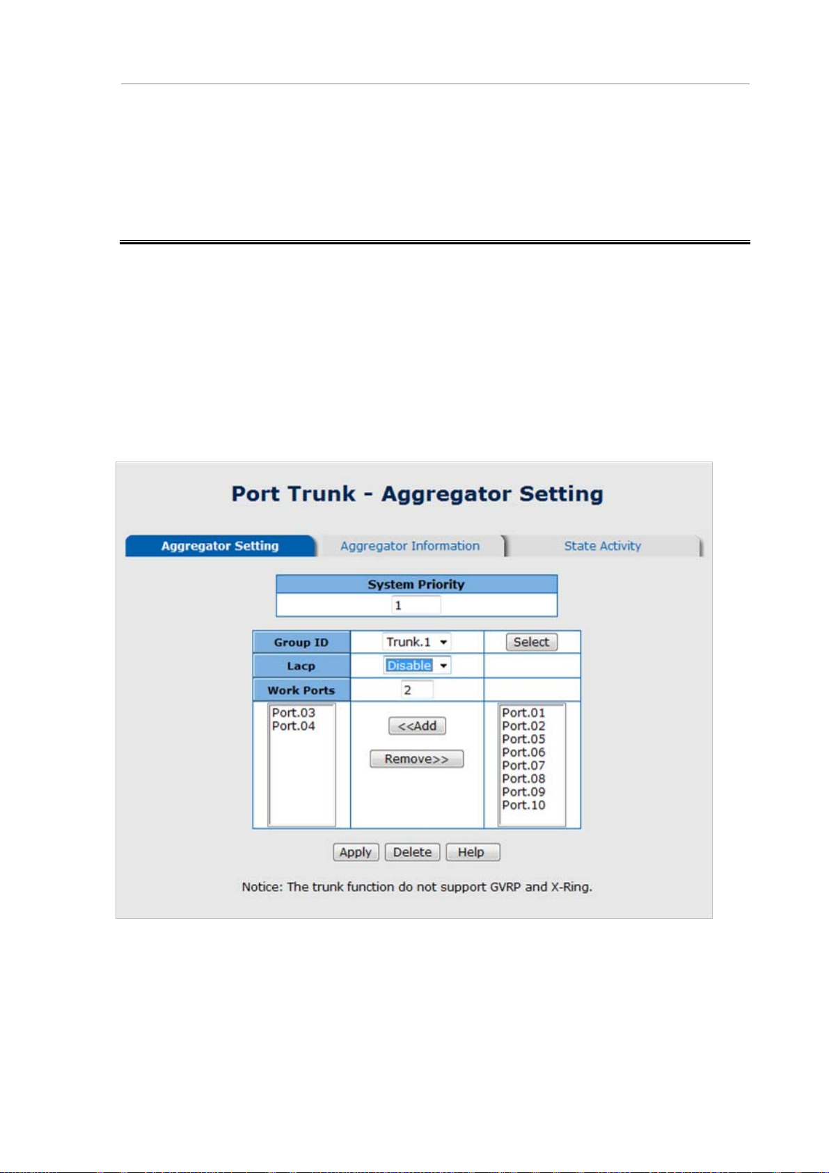
User’s Manual of ISW-1022M Series and ISW-1033MT
This column field allows the user to type in the total number of active port up to
four. With LACP static trunk group, e.g. you assign four ports to be the
Work ports:
members of a trunk group whose work ports column field is set as two; the
exceed ports are standby/redundant ports and can be aggregated if working
ports fail. If it is a static trunk group (non-LACP), the number of work ports must
equal the total number of group member ports.
5.5.3.2 Aggregator Information
When you had setup the LACP aggregator, you will see relation information in here.
LACP disabled
Having set up the aggregator setting with LACP disabled, you will see the local static trunk group information on the tab of
Aggregator Information.
Figure 5-21 Assigning 2 ports to a trunk group with LACP disabled
72
Page 73

Figure 5-22 Static Trunking Group information
The page includes the following fields:
Object Description
User’s Manual of ISW-1022M Series and ISW-1033MT
Group Key:
Port Member:
This is a read-only column field that displays the trunk group ID.
This is a read-only column field that displays the members of this static trunk
group.
LACP enabled
Having set up the aggregator setting with LACP enabled, you will see the trunking group information between two
switches on the tab of Aggregator Information.
Switch 1 configuration
1. Set System Priority of the trunk group. The default is 1.
2. Select a trunk group ID by pull down the drop-down menu bar.
3. Enable LACP.
4. Include the member ports by clicking the Add button after selecting the port number and the column field of
Work Ports changes automatically.
73
Page 74

User’s Manual of ISW-1022M Series and ISW-1033MT
Figure 5-23 Aggregation Information of Switch 1
5. Click on the tab of Aggregator Information to check the trunked group information as the illustration shown
above after the two switches configured.
Switch 2 configuration
6. Set System Priority of the trunk group. For example: 32768.
7. Select a trunk group ID by pull down the drop-down menu bar.
8. Enable LACP.
9. Include the member ports by clicking the Add button after selecting the port number and the column field of
Work Ports changes automatically.
74
Page 75

User’s Manual of ISW-1022M Series and ISW-1033MT
Figure 5-24 Switch 2 configuration interface
10. Click on the tab of Aggregator Information to check the trunked group information as the illustration shown
above after the two switches configured.
Figure 5-25 Switch 1 Aggregator Information
75
Page 76

User’s Manual of ISW-1022M Series and ISW-1033MT
5.5.3.3 State Activity
Having set up the LACP aggregator on the tab of Aggregator Setting, you can configure the state activity for the members
of the LACP trunk group. You can tick or cancel the checkbox beside the state label. When you remove the tick mark of
the port and click
The page includes the following fields:
Object Description
Apply
, the port state activity will change to
Passive
.
Figure 5-26 State Activity of Switch 1
Active: The port automatically sends LACP protocol packets.
Passive:
The port does not automatically send LACP protocol packets, and responds only
if it receives LACP protocol packets from the opposite device.
Figure 5-27 State Activity of Switch 2
A link having two passive LACP nodes will not perform dynamic LACP trunk because both
ports are waiting for an LACP protocol packet from the opposite device.
76
Page 77

User’s Manual of ISW-1022M Series and ISW-1033MT
5.5.4 Port Mirroring
The Port mirroring is a method for monitor traffic in switched networks. Traffic through ports can be monitored by one
specific port, which means traffic goes in or out monitored (source) ports will be duplicated into mirror (destination)
port.
Figure 5-28 Port Trunk – Port Mirroring interface
The page includes the following fields:
Object Description
There is only one port can be selected to be destination (mirror) port for
Destination Port:
Source Port:
monitoring both RX and TX traffic which come from source port. Or, use one of
two ports for monitoring RX traffic only and the other one for TX traffic only. User
can connect mirror port to LAN analyzer or Netxray.
The ports that user wants to monitor. All monitored port traffic will be copied to
mirror (destination) port. User can select multiple source ports by checking the
RX or TX check boxes to be monitored.
77
Page 78

User’s Manual of ISW-1022M Series and ISW-1033MT
5.5.5 Rate Limiting
You can set up every port’s bandwidth rate and frame limitation type.
Ingress Limit Frame type: select the frame type that wants to filter. There are four frame types for selecting:
¾ All
¾ Broadcast/Multicast/Flooded Unicast
¾ Broadcast/Multicast
¾ Broadcast only
Broadcast/Multicast/Flooded Unicast, Broadcast/Multicast and Bbroadcast only types are only for ingress
frames. The egress rate only supports All type.
Figure 5-29 Rate Limiting interface
All the ports support port ingress and egress rate control. For example, assume port 1 is 10Mbps, users can
set it’s effective egress rate is 1Mbps, ingress rate is 500Kbps. The switch performs the ingress rate by packet
counter to meet the specified rate
¾ Ingress: Enter the port effective ingress rate (The default value is “0”).
¾ Egress: Enter the port effective egress rate (The default value is “0”).
And then, click
Apply
to apply the settings
78
Page 79

User’s Manual of ISW-1022M Series and ISW-1033MT
5.6 Protocol
This section has the following items:
5.6.1 VLAN
5.6.2 Rapid Spanning Tree Protocol
5.6.3 SNMP
5.6.4 QoS
5.6.5 IGMP Snooping
5.6.1 VLAN configuration
5.6.1.1 VLAN Overview
A Virtual LAN (VLAN) is a logical network grouping that limits the broadcast domain. It allows you to isolate network traffic
so only members of the VLAN receive traffic from the same VLAN members. Basically, creating a VLAN from a switch is
logically equivalent of reconnecting a group of network devices to another Layer 2 switch. However, all the network
devices are still plug into the same switch physically.
The Managed Industrial Switch supports IEEE 802.1Q (tagged-based) and Port-Base VLAN setting in web management
page. In the default configuration, VLAN support is “Disable”.
Port-based VLAN
Port-based VLAN limit traffic that flows into and out of switch ports. Thus, all devices connected to a port are members of
the VLAN(s) the port belongs to, whether there is a single computer directly connected to a switch, or an entire
department.
On port-based VLAN.NIC do not need to be able to identify 802.1Q tags in packet headers. NIC send and receive normal
Ethernet packets. If the packet's destination lies on the same segment, communications take place using normal Ethernet
protocols. Even though this is always the case, when the destination for a packet lies on another switch port, VLAN
considerations come into play to decide if the packet is dropped by the Switch or delivered.
IEEE 802.1Q VLANs
IEEE 802.1Q (tagged) VLAN are implemented on the Switch. 802.1Q VLAN require tagging, which enables them to span
the entire network (assuming all switches on the network are IEEE 802.1Q-compliant).
VLAN allow a network to be segmented in order to reduce the size of broadcast domains. All packets entering a VLAN will
only be forwarded to the stations (over IEEE 802.1Q enabled switches) that are members of that VLAN, and this includes
broadcast, multicast and unicast packets from unknown sources.
VLAN can also provide a level of security to your network. IEEE 802.1Q VLAN will only deliver packets between stations
that are members of the VLAN. Any port can be configured as either tagging or untagging:
The untagging feature of IEEE 802.1Q VLAN allows VLAN to work with legacy switches that don't recognize
VLAN tags in packet headers.
79
Page 80

User’s Manual of ISW-1022M Series and ISW-1033MT
The tagging feature allows VLAN to span multiple 802.1Q-compliant switches through a single physical
connection and allows Spanning Tree to be enabled on all ports and work normally.
Some relevant terms:
Tagging - The act of putting 802.1Q VLAN information into the header of a packet.
Untagging - The act of stripping 802.1Q VLAN information out of the packet header.
802.1Q VLAN Tags
The figure below shows the 802.1Q VLAN tag. There are four additional octets inserted after the source MAC address.
Their presence is indicated by a value of 0x8100 in the Ether Type field. When a packet's Ether Type field is equal to
0x8100, the packet carries the IEEE 802.1Q/802.1p tag. The tag is contained in the following two octets and consists of 3
bits of user priority, 1 bit of Canonical Format Identifier (CFI - used for encapsulating Token Ring packets so they can be
carried across Ethernet backbones), and 12 bits of VLAN ID (VID). The 3 bits of user priority are used by 802.1p. The VID
is the VLAN identifier and is used by the 802.1Q standard. Because the VID is 12 bits long, 4094 unique VLAN can be
identified.
The tag is inserted into the packet header making the entire packet longer by 4 octets. All of the information originally
contained in the packet is retained.
802.1Q Tag
User Priority CFI VLAN ID (VID)
3 bits 1 bits 12 bits
TPID (Tag Protocol Identifier) TCI (Tag Control Information)
2 bytes 2 bytes
Preamble
Destination
Address
6 bytes 6 bytes 4 bytes 2 bytes 46-1517 bytes 4 bytes
Source
Address
VLAN TAG
Ethernet
Type
Data FCS
The Ether Type and VLAN ID are inserted after the MAC source address, but before the original Ether Type/Length or
Logical Link Control. Because the packet is now a bit longer than it was originally, the Cyclic Redundancy Check (CRC)
must be recalculated.
80
Page 81

User’s Manual of ISW-1022M Series and ISW-1033MT
Adding an IEEE802.1Q Tag
Dest. Addr. Src. Addr. Length/E. type Data Old CRC
Dest. Addr. Src. Addr. E. type Tag Length/E. type Data New CRC
Original Ethernet
Priority CFI VLAN ID
New Tagged Packet
Port VLAN ID
Packets that are tagged (are carrying the 802.1Q VID information) can be transmitted from one 802.1Q compliant network
device to another with the VLAN information intact. This allows 802.1Q VLAN to span network devices (and indeed, the
entire network – if all network devices are 802.1Q compliant).
Every physical port on a switch has a PVID. 802.1Q ports are also assigned a PVID, for use within the switch. If no VLAN
are defined on the switch, all ports are then assigned to a default VLAN with a PVID equal to 1. Untagged packets are
assigned the PVID of the port on which they were received. Forwarding decisions are based upon this PVID, in so far as
VLAN are concerned. Tagged packets are forwarded according to the VID contained within the tag. Tagged packets are
also assigned a PVID, but the PVID is not used to make packet forwarding decisions, the VID is.
Tag-aware switches must keep a table to relate PVID within the switch to VID on the network. The switch will compare the
VID of a packet to be transmitted to the VID of the port that is to transmit the packet. If the two VID are different the switch
will drop the packet. Because of the existence of the PVID for untagged packets and the VID for tagged packets,
tag-aware and tag-unaware network devices can coexist on the same network.
A switch port can have only one PVID, but can have as many VID as the switch has memory in its VLAN table to store
them.
Because some devices on a network may be tag-unaware, a decision must be made at each port on a tag-aware device
before packets are transmitted – should the packet to be transmitted have a tag or not? If the transmitting port is
connected to a tag-unaware device, the packet should be untagged. If the transmitting port is connected to a tag-aware
device, the packet should be tagged.
Default VLANs
The Switch initially configures one VLAN, VID = 1, called "default." The factory default setting assigns all ports on the
Switch to the "default". As new VLAN are configured in Port-based mode, their respective member ports are removed
from the "default."
81
Page 82

User’s Manual of ISW-1022M Series and ISW-1033MT
1 No matter what basis is used to uniquely identify end nodes and assign these nodes
VLAN membership, packets cannot cross VLAN without a network device performing a
routing function between the VLAN.
2 The Switch supports Port-based VLAN and IEEE 802.1Q VLAN. The port untagging
function can be used to remove the 802.1 tag from packet headers to maintain
compatibility with devices that are tag-unaware.
5.6.1.2 VLAN Configuration
A Virtual LAN (VLAN) is a logical network grouping that limits the broadcast domain. It allows you to isolate network traffic
so only members of the VLAN receive traffic from the same VLAN members. Basically, creating a VLAN from a switch is
logically equivalent of reconnecting a group of network devices to another Layer 2 switch. However, all the network
devices are still plug into the same switch physically.
The Industrial Switch supports Port-based, 802.1Q (Tagged-based) and GVRP VLAN in web management page. In the
default configuration, VLAN support is “Disable”.
5.6.1.3 Port-based VLAN
Figure 5-30 VLAN Configuration interface
A port-based VLAN basically consists of its members—ports, which means the VLAN is created by grouping the selected
ports. This method provides the convenience for users to configure a simple VLAN easily without complicated steps.
Packets can go among only members of the same VLAN group. Note all unselected ports are treated as belonging to
another single VLAN. If the port-based VLAN enabled, the VLAN-tagging is ignored. The port-based VLAN function allows
the user to create separate VLANs to limit the unnecessary packet flooding; however, for the purpose of sharing resource,
a single port called a common port can belongs to different VLANs, which all the member devices (ports) in different
VLANs have the permission to access the common port while they still cannot communicate with each other in different
VLANs.
82
Page 83

User’s Manual of ISW-1022M Series and ISW-1033MT
Figure 5-31 VLAN – Port Based interface
Click
Pull down the selection item and focus on
Mode in
Add
Port Based
to add a new VLAN group (The maximum VLAN groups are up to 64).
mode.
Port Based
then press
Apply
to set the VLAN Operation
Figure 5-32 VLAN—Port Based Add interface
Enter the group name and VLAN ID. Add the selected port number into the right field to group these members
to be a VLAN group, or remove any of them listed in the right field from the VLAN.
And then, click
You will see the VLAN list displays.
Apply
to have the configuration take effect.
83
Page 84

User’s Manual of ISW-1022M Series and ISW-1033MT
Figure 5-33 VLAN—Port Based Edit/Delete interface
Use
Use
Delete
Edit
to delete the VLAN.
to modify group name, VLAN ID, or add/remove the members of the existing VLAN group.
Remember to execute the “Save Configuration” action, otherwise the new configuration will
lose when switch power off.
5.6.1.4 802.1Q VLAN
Virtual Local Area Network (VLAN) can be implemented on the Industrial Switch to logically create different broadcast
domain.
When the 802.1Q VLAN function is enabled, all ports on the switch belong to default VLAN of VID 1, which means they
logically are regarded as members of the same broadcast domain. The valid VLAN ID is in the range of number between 1
and 4094. The amount of VLAN groups is up to 256 including default VLAN that cannot be deleted.
Each member port of 802.1Q is on either an Access Link (no VLA N-tagged) or a T runk Link (VLAN-tagged). All frames
on an Access Link carry no VLAN identification. Conversely, all frames on a Trunk Link are VLAN-tagged. Besides, there
is the third mode—Hybrid. A Hybrid Link can carry both VLAN-tagged frames and untagged frames. A single port is
supposed to belong to one VLAN group, except it is on a Trunk/Hybrid Link.
The technique of 802.1Q tagging inserts a 4-byte tag, including VLAN ID of the destination port—PVID, in the frame. With
the combination of Access/Trunk/Hybrid Links, the communication across switches also can make the packet sent through
tagged and untagged ports.
84
Page 85

User’s Manual of ISW-1022M Series and ISW-1033MT
802.1Q VLAN Port Configuration
This page is used for configuring the Industrial Switch port VLAN. The VLAN per Port Configuration page contains fields
for managing ports that are part of a VLAN. The port default VLAN ID (PVID) is configured on the VLAN Port Configuration
page. All untagged packets arriving to the device are tagged by the ports PVID.
Understand nomenclature of the S witch
■ IEEE 802.1Q Tagged and Untagged
Every port on an 802.1Q compliant switch can be configured as tagged or untagged.
• Tagged
(Trunk Link)
• Untgged
(Access Link)
Frame Leave
Leave port is tagged Frame remains tagged Tag is inserted
Leave port is untagged Tag is removed Frame remain untagged
Ports with tagging enabled will put the VID number, priority and other VLAN information into the
header of all packets that flow into those ports. If a packet has previously been tagged, the port
will not alter the packet, thus keeping the VLAN information intact. The VLAN information in the
tag can then be used by other 802.1Q compliant devices on the network to make
packet-forwarding decisions.
Ports with untagging enabled will strip the 802.1Q tag from all packets that flow into those
ports. If the packet doesn't have an 802.1Q VLAN tag, the port will not alter the packet. Thus,
all packets received by and forwarded by an untagging port will have no 802.1Q VLAN
information. (Remember that the PVID is only used internally within the Switch). Untagging is
used to send packets from an 802.1Q-compliant network device to a non-compliant network
device.
Frame Income
Income Frame is tagged Income Frame is untagged
Here pay attention to the explaining of “Access”, “Trunk” and “Hybrid”.
。 Access: Ports will strip the 802.1Q tag from all packets that out of those ports. If the packet doesn’t have an 802.1Q
VLAN tag, the port will not alter the packet. Thus, all packets received by and forwarded by an untagging port will
have no 802.1Q VLAN information. Untagging is used to send packets from an 802.1Q-compliant network device to
a non-compliant network device.
Ports with “Access” mode belong to a single untagged VLAN.
。 Trunk: Ports with tagging enabled will put the VID number, priority and other VLAN information into the header of all
packets that out of those ports. If a packet has previously been tagged, the port will not alter the packet, thus
keeping the VLAN information intact. The VLAN information in the tag can then be used by other 802.1Q compliant
devices on the network to make packet forwarding decisions.
85
Page 86

User’s Manual of ISW-1022M Series and ISW-1033MT
。 Hybrid: The port belongs to VLANs, and each VLAN is user-defined as tagged or untagged (full 802.1Q mode).
Ports will strip the 802.1Q tag from all packets that out of those ports.
Port Mode VLAN Membership Frame Leave
Access Link Belongs to a single untagged VLAN
Allowed to belongs to multiple Tagged
Trunk Link
VLANs at the same time
Allowed to belongs to multiple untagged
Hybrid Link
VLANs at the same time
The 802.1Q VLAN Port Configuration screenshot as below:
Untagged
( Tag=PVID be removed)
Tagged
(Tag=PVID or Original VID be remained)
Untagged by specify VID
The page includes the following fields:
Object Description
GVRP (GARP VLAN Registration Protocol) is a protocol that facilitates control
Enable GVRP Protocol:
of virtual local area networks (VLANs) within a larger network. GVRP conforms to
the IEEE 802.1Q specification, which defines a method of tagging frames with
Figure 5-34 802.1Q VLAN mode
86
Page 87

Management VLAN ID:
Link Type:
Untagged VID:
User’s Manual of ISW-1022M Series and ISW-1033MT
VLAN configuration data. This allows network devices to dynamically exchange
VLAN configuration information with other devices.
For example, having enabled GVRP on two switches, they are able to
automatically exchange the information of their VLAN database. Therefore, the
user doesn’t need to manually configure whether the link is trunk or hybrid, the
packets belonging to the same VLAN can communicate across switches. Tick
this checkbox to enable GVRP protocol. This checkbox is available while the
VLAN Operation Mode is in 802.1Q mode.
Only when the VLAN members, whose Untagged VID (PVID) equals to the value
in this column, will have the permission to access the switch. The default value is
‘0’ that means this limit is not enabled (all members in different VLANs can
access this switch).
There are 3 types of link type.
Access Link:
A segment which provides the link path for one or more stations to the
VLAN-aware device. An Access Port (untagged port), connected to the access
link, has an untagged VID (also called PVID). After an untagged frame gets
into the access port, the switch will insert a four-byte tag in the frame. The
contents of the last 12-bit of the tag is untagged VID. When this frame is sent
out through any of the access port of the same PVID, the switch will remove
the tag from the frame to recover it to what it was. Those ports of the same
untagged VID are regarded as the same VLAN group members.
Trunk Link:
A segment which provides the link path for one or more VLAN-aware devices
(switches). A Trunk Port, connected to the trunk link, has an understanding of
tagged frame, which is used for the communication among VLANs across
switches. Which frames of the specified VIDs will be forwarded depends on the
values filled in the Tagged VID column field. Please insert a comma between
two VIDs.
Hybrid Link:
A segment which consists of Access and Trunk links. The hybrid port has both
the features of access and trunk ports. A hybrid port has a PVID belonging to a
particular VLAN, and it also forwards the specified tagged-frames for the
purpose of VLAN communication across switches.
This column field is available when Link Type is set as Access Link and Hybrid
Link. Assign a number in the range between 1 an 4094.
Tagged VID:
This column field is available when Link Type is set as Trunk Link and Hybrid
Link. Assign a number in the range between 1 an 4094.
87
Page 88

User’s Manual of ISW-1022M Series and ISW-1033MT
Access Link
Because the access port doesn’t have an understanding of tagged frame, the column field of
Tagged VID is not available.
Trunk Link
1. A trunk port doesn’t insert tag into an untagged frame, and therefore the untagged VID
column field is not available.
2. It’s not necessary to type ‘1’ in the tagged VID. The trunk port will forward the frames of
VLAN 1.
3. The trunk port has to be connected to a trunk/hybrid port of the other switch. Both the
tagged VID of the two ports have to be the same.
Hybrid Link
1. It’s not necessary to type ‘1’ in the tagged VID. The hybrid port will forward the frames of
VLAN 1.
2. The trunk port has to be connected to a trunk/hybrid port of the other switch. Both the
tagged VID of the two ports have to be the same.
Pull down the selection item and focus on
802.1Q
You can see the link type, untagged VID, and tagged VID information of each port in the table below on the
screen.
mode
802.1Q
then press
Apply
to set the VLAN Operation Mode in
Figure 5-35 802.1Q VLAN interface
88
Page 89

Group Configuration
Edit the existing VLAN Group.
Select the VLAN group in the table list.
User’s Manual of ISW-1022M Series and ISW-1033MT
Click
Edit
.
Figure 5-36 Group Configuration interface
You can modify the VLAN group name and VLAN ID.
Click
Apply
Figure 5-37 Group Configuration interface
.
89
Page 90

User’s Manual of ISW-1022M Series and ISW-1033MT
5.6.2 Rapid Spanning Tree
The Rapid Spanning Tree Protocol (RSTP) is an evolution of the Spanning Tree Protocol and provides for faster
spanning tree convergence after a topology change. The system also supports STP and the system will auto-detect the
connected device that is running STP or RSTP protocol.
5.6.2.1 Theory
The Spanning Tree protocol can be used to detect and disable network loops, and to provide backup links between
switches, bridges or routers. This allows the switch to interact with other bridging devices in your network to ensure that
only one route exists between any two stations on the network, and provide backup links which automatically take over
when a primary link goes down. The spanning tree algorithms supported by this switch include these versions:
STP – Spanning Tree Protocol (IEEE 802.1D)
RSTP – Rapid Spanning Tree Protocol (IEEE 802.1w)
The IEEE 802.1D Spanning Tree Protocol and IEEE 802.1W Rapid Spanning Tree Protocol allow for the blocking of
links between switches that form loops within the network. When multiple links between switches are detected, a primary
link is established. Duplicated links are blocked from use and become standby links. The protocol allows for the duplicate
links to be used in the event of a failure of the primary link. Once the Spanning Tree Protocol is configured and enabled,
primary links are established and duplicated links are blocked automatically. The reactivation of the blocked links (at the
time of a primary link failure) is also accomplished automatically without operator intervention.
This automatic network reconfiguration provides maximum uptime to network users. However, the concepts of the
Spanning Tree Algorithm and protocol are a complicated and complex subject and must be fully researched and
understood. It is possible to cause serious degradation of the performance of the network if the Spanning Tree is
incorrectly configured. Please read the following before making any changes from the default values.
The Switch STP performs the following functions:
Creates a single spanning tree from any combination of switching or bridging elements.
Creates multiple spanning trees – from any combination of ports contained within a single switch, in user
specified groups.
Automatically reconfigures the spanning tree to compensate for the failure, addition, or removal of any
element in the tree.
Reconfigures the spanning tree without operator intervention.
Bridge Protocol Data Units
For STP to arrive at a stable network topology, the following information is used:
The unique switch identifier
The path cost to the root associated with each switch port
The por tidentifier
STP communicates between switches on the network using Bridge Protocol Data Units (BPDUs). Each BPDU contains
the following information:
The unique identifier of the switch that the transmitting switch currently believes is the root switch
90
Page 91

User’s Manual of ISW-1022M Series and ISW-1033MT
The path cost to the root from the transmitting port
The port identifier of the transmitting port
The switch sends BPDUs to communicate and construct the spanning-tree topology. All switches connected to the LAN on
which the packet is transmitted will receive the BPDU. BPDUs are not directly forwarded by the switch, but the receiving
switch uses the information in the frame to calculate a BPDU, and, if the topology changes, initiates a BPDU transmission.
The communication between switches via BPDUs results in the following:
One switch is elected as the root switch
The shortest distance to the root switch is calculated for each switch
A designated switch is selected. This is the switch closest to the root switch through which packets will be
forwarded to the root.
A port for each switch is selected. This is the port providing the best path from the switch to the root switch.
Ports included in the STP are selected.
Creating a Stable STP Topology
It is to make the root port a fastest link. If all switches have STP enabled with default settings, the switch with the lowest
MAC address in the network will become the root switch. By increasing the priority (lowering the priority number) of the
best switch, STP can be forced to select the best switch as the root switch.
When STP is enabled using the default parameters, the path between source and destination stations in a switched
network might not be ideal. For instance, connecting higher-speed links to a port that has a higher number than the
current root port can cause a root-port change.
STP Port States
The BPDUs take some time to pass through a network. This propagation delay can result in topology changes where a
port that transitioned directly from a Blocking state to a Forwarding state could create temporary data loops. Ports must
wait for new network topology information to propagate throughout the network before starting to forward packets. They
must also wait for the packet lifetime to expire for BPDU packets that were forwarded based on the old topology. The
forward delay timer is used to allow the network topology to stabilize after a topology change. In addition, STP specifies a
series of states a port must transition through to further ensure that a stable network topology is created after a topology
change.
Each port on a switch using STP exists is in one of the following five states:
Blocking – the port is blocked from forwarding or receiving packets
Listening – the port is waiting to receive BPDU packets that may tell the port to go back to the blocking state
Learning – the port is adding addresses to its forwarding database, but not yet forwarding packets
Forwarding – the port is forwarding packets
Disabled – the port only responds to network management messages and must return to the blocking state
first
91
Page 92

User’s Manual of ISW-1022M Series and ISW-1033MT
A port transitions from one state to another as follows:
From initialization (switch boot) to blocking
From blocking to listening or to disabled
From listening to learning or to disabled
From learning to forwarding or to disabled
From forwarding to disabled
From disabled to blocking
Switch
Blocking
Listening
Learning
Forwarding
Figure 5-38 STP Port State Transitions
You can modify each port state by using management software. When you enable STP, every port on every switch in the
network goes through the blocking state and then transitions through the states of listening and learning at power up. If
properly configured, each port stabilizes to the forwarding or blocking state. No packets (except BPDUs) are forwarded
from, or received by, STP enabled ports until the forwarding state is enabled for that port.
Disable
5.6.2.2 RSTP Parameters
RSTP Operation Levels
The Switch allows for two levels of operation: the switch level and the port level. The switch level forms a spanning tree
consisting of links between one or more switches. The port level constructs a spanning tree consisting of groups of one or
more ports. The RSTP operates in much the same way for both levels.
On the switch level, RSTP calculates the Bridge Identifier for each switch and then sets the Root
Bridge and the Designated Bridges.
On the port level, RSTP sets the Root Port and the Designated Ports.
92
Page 93

User’s Manual of ISW-1022M Series and ISW-1033MT
The following are the user-configurable RSTP parameters for the switch level:
Parameter Description Default Value
Bridge Identifier(Not user
configurable
except by setting priority
below)
Priority
Hello Time
Maximum Age Timer
Forward Delay Timer
A combination of the User-set priority and
the switch’s MAC address.
The Bridge Identifier consists of two parts:
a 16-bit priority and a 48-bit Ethernet MAC
address 32768 + MAC
A relative priority for each switch – lower
numbers give a higher priority and a greater
chance of a given switch being elected as
the root bridge
The length of time between broadcasts of
the hello message by the switch
Measures the age of a received BPDU for a
port and ensures that the BPDU is discarded
when its age exceeds the value of the
maximum age timer.
The amount time spent by a port in the
32768 + MAC
32768
2 seconds
20 seconds
15 seconds
The following are the user-configurable RSTP parameters for the port or port group level:
Variable Description Default Value
Port Priority
Port Cost
Default Spanning-Tree Configuration
A relative priority for each
port –lower numbers give a higher priority
and a greater chance of a given port being
elected as the root port
A value used by RSTP to evaluate paths –
STP calculates path costs and selects the
path with the minimum cost as the active
path
learning and listening states waiting for a
BPDU that may return the port to the
blocking state.
128
200,000-100Mbps Fast Ethernet ports
20,000-1000Mbps Gigabit Ethernet
ports
0 - Auto
Feature Default Value
Enable state RSTP disabled for all ports
Port priority 128
Port cost 0
Bridge Priority 32,768
93
Page 94

User’s Manual of ISW-1022M Series and ISW-1033MT
User-Changeable STA Parameters
The Switch’s factory default setting should cover the majority of installations. However, it is advisable to keep the default
settings as set at the factory; unless, it is absolutely necessary. The user changeable parameters in the Switch are as
follows:
Priority – A Priority for the switch can be set from 0 to 65535. 0 is equal to the highest Priority.
Hello Time – The Hello Time can be from 1 to 10 seconds. This is the interval between two transmissions of BPDU
packets sent by the Root Bridge to tell all other Switches that it is indeed the Root Bridge. If you set a Hello Time for your
Switch, and it is not the Root Bridge, the set Hello Time will be used if and when your Switch becomes the Root Bridge.
The Hello Time cannot be longer than the Max. Age. Otherwise, a configuration error will
occur.
Max. Age – The Max Age can be from 6 to 40 seconds. At the end of the Max Age, if a BPDU has still not been received
from the Root Bridge, your Switch will start sending its own BPDU to all other Switches for permission to become the Root
Bridge. If it turns out that your Switch has the lowest Bridge Identifier, it will become the Root Bridge.
Forward Delay Timer – The Forward Delay can be from 4 to 30 seconds. This is the time any port on the
Switch spends in the listening state while moving from the blocking state to the forwarding state.
Observe the following formulas when setting the above parameters:
Max. Age _ 2 x (Forward Delay - 1 second)
Max. Age _ 2 x (Hello Time + 1 second)
Port Priority – A Port Priority can be from 0 to 240. The lower the number, the greater the probability the port will be
chosen as the Root Port.
Port Cost – A Port Cost can be set from 0 to 200000000. The lower the number, the greater the probability the port will be
chosen to forward packets.
5.6 2.3 Illustration of STP
A simple illustration of three switches connected in a loop is depicted in the below diagram. In this example, you can
anticipate some major network problems if the STP assistance is not applied.
If switch A broadcasts a packet to switch B, switch B will broadcast it to switch C, and switch C will broadcast it to back to
switch A and so on. The broadcast packet will be passed indefinitely in a loop, potentially causing a network failure. In this
example, STP breaks the loop by blocking the connection between switch B and C. The decision to block a particular
connection is based on the STP calculation of the most current Bridge and Port settings.
Now, if switch A broadcasts a packet to switch C, then switch C will drop the packet at port 2 and the broadcast will end
there. Setting-up STP using values other than the defaults, can be complex. Therefore, you are advised to keep the
default factory settings and STP will automatically assign root bridges/ports and block loop connections. Influencing STP
to choose a particular switch as the root bridge using the Priority setting, or influencing STP to choose a particular port to
94
Page 95

User’s Manual of ISW-1022M Series and ISW-1033MT
block using the Port Priority and Port Cost settings is, however, relatively straight forward.
LAN 1
Portcast = 19
Port 3
A
Bridge ID = 15
Port 1
Port 2
Portcast = 4
Portcast = 4
Port 1
B
Bridge ID = 30
Port 2
Port 3
Portcast = 19 Portcast = 19
LAN 2 LAN 3
Figure 5-39 Before Applying the STA Rules
In this example, only the default STP values are used.
A
Port 1
Portcast = 19
LAN 1
Port 3
Root Bridge
Portcast = 4
Port 2
Portcast = 4
C
Port 2
Port 1
Bridge ID = 20
Port 3
Designated Port
Root Port
Port 1
B
Port 2
Port 3
LAN 2 LAN 3
Blocked
Designated Port
Root Port
C
Designated Bridge
Port 2
Port 1
Port 3
Figure 5-40 After Applying the STA Rules
The switch with the lowest Bridge ID (switch C) was elected the root bridge, and the ports were selected to give a high port
cost between switches B and C. The two (optional) Gigabit ports (default port cost = 4) on switch A are connected to one
(optional) Gigabit port on both switch B and C. The redundant link between switch B and C is deliberately chosen as a 100
95
Page 96

User’s Manual of ISW-1022M Series and ISW-1033MT
Mbps Fast Ethernet link (default port cost = 19). Gigabit ports could be used, but the port cost should be increased from
the default to ensure that the link between switch B and switch C is the blocked link.
5.6.2.4 RSTP System Configuration
This section provides RSTP-System Configuration from the Switch, the screen in Figure 5-41 appears.
The user can view spanning tree information of Root Bridge.
The user can modify RSTP state. After modification, click
Apply
.
Figure 5-41 RSTP System Configuration interface
The page includes the following fields:
Object Description
RSTP mode:
The user must enable the RSTP function first before configuring the related
parameters.
96
Page 97

User’s Manual of ISW-1022M Series and ISW-1033MT
The switch with the lowest value has the highest priority and is selected as the
Priority (0-61440):
Max Age (6-40):
Hello Time (1-10):
Forward Delay Time
(4-30):
root. If the value is changed, the user must reboot the switch.
The value must be a multiple of 4096 according to the protocol standard rule.
The number of seconds a switch waits without receiving Spanning-tree Protocol
configuration messages before attempting a reconfiguration.
Enter a value between 6 through 40.
The time that controls the switch to send out the BPDU packet to check RSTP
current status.
Enter a value between 1 through 10.
The number of seconds a port waits before changing from its Rapid
Spanning-Tree Protocol learning and listening states to the forwarding state.
Enter a value between 4 through 30.
Follow the rule as below to configure the MAX Age, Hello Time, and Forward Delay Time.
2 x (Forward Delay Time value –1) > = Max Age value >= 2 x (Hello Time value +1)
97
Page 98

User’s Manual of ISW-1022M Series and ISW-1033MT
5.6.2.5 Port Configuration
This web page provides the port configuration interface for RSTP. You can assign higher or lower priority to each port.
Rapid spanning tree will have the port with the higher priority in forwarding state and block other ports to make certain that
there is no loop in the LAN.
Figure 5-42 RSTP Port Configuration interface
The page includes the following fields:
Object Description
Path Cost:
Priority:
The cost of the path to the other bridge from this transmitting bridge at the
specified port. Enter a number 1 through 200,000,000.
Decide which port should be blocked by setting its priority as the lowest. Enter a
number between 0 and 240. The value of priority must be the multiple of 16.
98
Page 99

Admin P2P:
User’s Manual of ISW-1022M Series and ISW-1033MT
The rapid state transitions possible within RSTP are dependent upon whether the
port concerned can only be connected to exactly another bridge (i.e. it is served
by a point-to-point LAN segment), or can be connected to two or more bridges
(i.e. it is served by a shared medium LAN segment). This function allows the P2P
status of the link to be manipulated administratively. True means the port is
regarded as a point-to-point link. False means the port is regarded as a shared
link. Auto means the link type is determined by the auto-negotiation between the
two peers.
Admin Edge:
Admin Non STP:
Path cost “0” is used to indicate auto-configuration mode. When the short path cost method is selected
and the default path cost recommended by the IEEE 8021w standard exceeds 65,535, the default is set
to 65,535.
By default, the system automatically detects the speed and duplex mode used on each port, and configures the path cost
according to the values shown below.
Port Type IEEE 802.1D-1998 IEEE 802.1w-2001
Ethernet
Fast Ethernet
Gigabit Ethernet
The port directly connected to end stations won’t create bridging loop in the
network. To configure the port as an edge port, set the port to “True” status.
The port includes the STP mathematic calculation. True is not including STP
mathematic calculation. False is including the STP mathematic calculation.
50-600 200,000-20,000,000
10-60 20,000-2,000,000
3-10 2,000-200,000
Table 5-6-1 Recommended STP Path Cost Range
Port Type Link Type IEEE 802.1D-1998 IEEE 802.1w-2001
Ethernet
Fast Ethernet
Gigabit Ethernet
Half Duplex
Full Duplex
Trunk
Half Duplex
Full Duplex
Trunk
Full Duplex
Trunk
Table 5-6-2 Recommended STP Path Costs
100
95
90
19
18
15
4
3
99
2,000,000
1,999,999
1,000,000
200,000
100,000
50,000
10,000
5,000
Page 100

User’s Manual of ISW-1022M Series and ISW-1033MT
A
5.6.3 SNMP Configuration
Simple Network Management Protocol (SNMP) is the protocol developed to manage nodes (servers, workstations,
routers, switches and hubs etc.) on an IP network. SNMP enables network administrators to manage network
performance, find and solve network problems, and plan for network growth. Network management systems learn of
problems by receiving traps or change notices from network devices implementing SNMP.
5.6.3.1 System Configuration
Figure 5-43 SNMP System Configuration interface
The page includes the following fields:
Object Description
Community Strings: Here you can define the new community string set and remove the unwanted
community string.
String: Fill the name string.
RO: Read only. Enables requests accompanied by this community string to
display MIB-object information.
RW: Read/write. Enables requests accompanied by this community string to
display MIB-object information and to set MIB objects.
Click
To remove the community string, select the community string that you defined
dd
.
100
 Loading...