

Page 1

Industrial Single-Port 10/100/1000Mbps
802.3bt PoE Injector
IPOE-171 Series
User’s Manual
Page 2

Copyright
Copyright © 2018 by PLANET Technology Corp. All rights reserved. No
part of this publication may be reproduced, transmitted, transcribed,
stored in a retrieval system, or translated into any language or
computer language, in any form or by any means, electronic,
mechanical, magnetic, optical, chemical, manual or otherwise, without
the prior written permission of PLANET.
PLANET makes no representations or warranties, either expressed or
implied, with respect to the contents hereof and specically disclaims
any warranties, merchantability or tness for any particular purpose.
Any software described in this manual is sold or licensed "as is".
Should the programs prove defective following their purchase, the
buyer (and not PLANET, its distributor, or its dealer) assumes the
entire cost of all necessary servicing, repair, and any incidental or
consequential damages resulting from any defect in the software.
Further, PLANET reserves the right to revise this publication and
to make changes from time to time in the contents hereof without
obligation to notify any person of such revision or changes.
All brand and product names mentioned in this manual are trademarks
and/or registered trademarks of their respective holders.
Trademarks
PLANET is a registered trademark of PLANET Technology Corp.
All other trademarks belong to their respective owners.
Disclaimer
PLANET Technology does not warrant that the hardware will work
properly in all environments and applications, and makes no warranty
and representation, either implied or expressed, with respect to
the quality, performance, merchantability, or tness for a particular
purpose.
PLANET has made every effort to ensure that this User’s Manual is
accurate; PLANET disclaims liability for any inaccuracies or omissions
that may have occurred. Information in this User’s Manual is subject
to change without notice and does not represent a commitment on the
part of PLANET. PLANET assumes no responsibility for any inaccuracies
that may be contained in this User’s Manual. PLANET makes no
commitment to update or keep current the information in this User’s
Page 3

Manual, and reserves the right to make improvements to this User’s
Manual and/or to the products described in this User’s Manual, at
any time without notice. If you nd information in this manual that
is incorrect, misleading, or incomplete, we would appreciate your
comments and suggestions.
FCC Warning
This equipment has been tested and found to comply with the limits
for a Class A digital device, pursuant to Part 15 of the FCC Rules.
These limits are designed to provide reasonable protection against
harmful interference when the equipment is operated in a commercial
environment. This equipment generates, uses, and can radiate radio
frequency energy and, if not installed and used in accordance with
the Instruction manual, may cause harmful interference to radio
communications. Operation of this equipment in a residential area
is likely to cause harmful interference in which case the user will be
required to correct the interference at his own expense.
CE Mark Warning
This is a Class A product. In a domestic environment, this product may
cause radio interference, in which case the user may be required to
take adequate measures.
WEEE Warning
To avoid the potential effects on the environment and human
health as a result of the presence of hazardous substances in
electrical and electronic equipment, end users of electrical
and electronic equipment should understand the meaning of
the crossed-out wheeled bin symbol. Do not dispose of WEEE as
unsorted municipal waste and have to collect such WEEE separately.
Revision
PLANET IPOE-171 Series User’s Manual
MODEL: IPOE-171-60W, IPOE-171-95W
REVISION: 1.0 (April, 2018)
Part No.: 2350-AF0510-000
Page 4

Table of Contents
1. Introduction ............................................................................... 5
2. Product Features ........................................................................ 6
3. Product Specications ................................................................. 8
4. Product Outlook ........................................................................10
4.1 Physical Dimensions (example on IPOE-171A-95W) ...............10
4.2 Product Outlook ..................................................................11
4.3 Industrial PoE+ Injector Upper Panel ....................................14
4.4 Wiring the Power Inputs ......................................................15
4.5 Wiring the Fault Alarm Contact ............................................16
5. Mounting Installation .................................................................17
5.1 DIN-rail Mounting ...............................................................17
5.2 Removing Device from DIN Rail ...........................................18
5.3 Wall-mount Plate Mounting ..................................................19
6. Hardware Installation .................................................................20
6.1 Before Installation ...............................................................20
6.2 IPOE-171-60W Installation ...................................................20
6.3 IPOE-171-60W and IPOE-171S Installation ............................22
6.4 IPOE-171-60W and IPOE-E172 Installation ............................23
7. Customer Support .....................................................................25
Page 5
1. Introduction
Thank you for purchasing PLANET IPOE-171 Single-port 10/100/1000Mbps
series injector.
Model LAN Port Speed PoE Standard PoE Budget
IPOE-171-60W 10/100/1000Mbps IEEE 802.3af/at/bt 60 watts
IPOE-171-95W 10/100/1000Mbps IEEE 802.3af/at/bt 95 watts
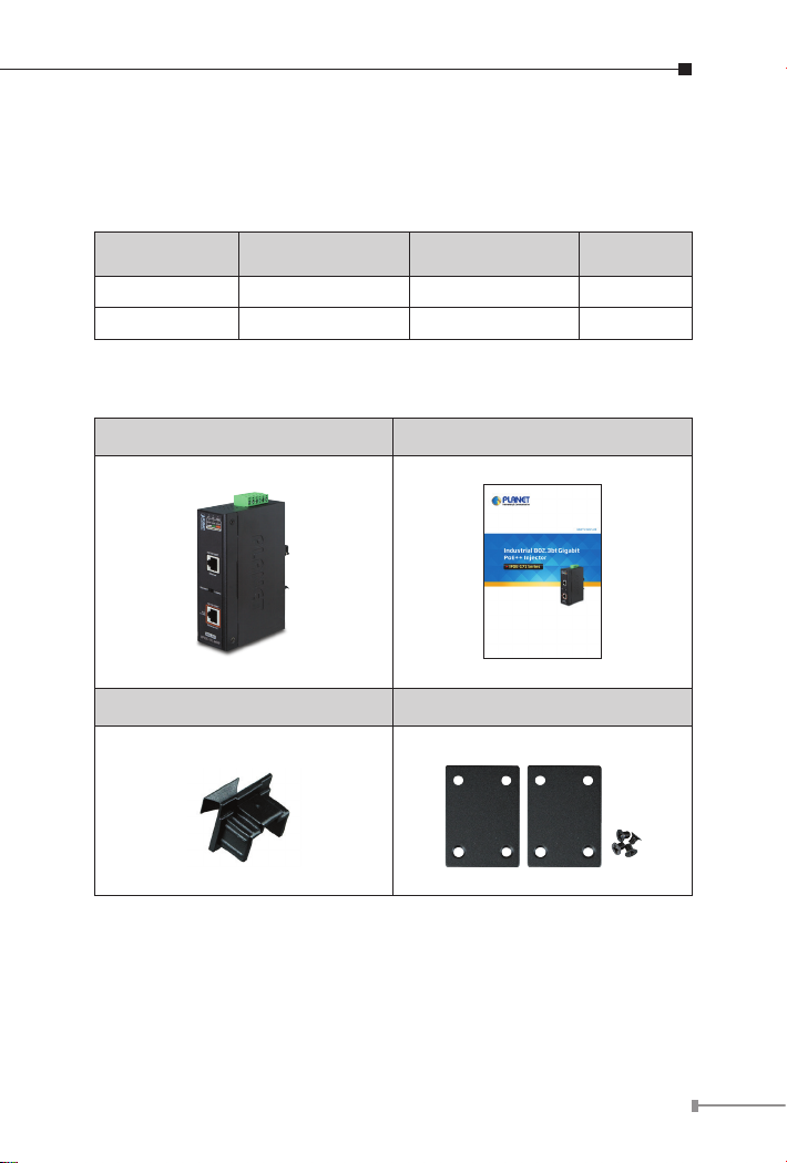
Please unpack the box of the device carefully, and the box should
contain the following items:
802.3bt PoE injector x 1 User’s manual x 1
Dust cap x 2 Wall-mount Kit x 1
If any item is found missing or damaged, please contact your local
reseller for replacement.
5
Page 6

2. Product Features
Interface
2 RJ45 interfaces
¾ 1-port Data + Power output
¾ 1-port Data input
1 terminal block for master and slave power input
¾ IPOE-171-60W Power Range: 48 ~ 56V DC redundant power
¾ IPOE-171-95W Power Range: 24 ~ 48V DC redundant power
Power over Ethernet
Complies with IEEE 802.3af/at/bt PoE end-span/mid-span PSE
Supports PoE power up to 60/95 watts for PoE port
Auto-detection of PoE IEEE 802.3af/at/bt equipment and devices
from being damaged by incorrect installation
Monitor the status of the total PoE usage in real time
Remote power feeding up to 100m
IPOE-171-60W with power on voltage indication
Hardware
IP30 slim type metal case
LED indicators for Power LED, PoE-in-Use LED and PoE Usage LED
Industrial Case and Installation
Solid wall mount or DIN-rail mount installation
Supports 6KV DC Ethernet ESD protection
-40 to 75 degrees C operating temperature
Standard Compliance
IEEE 802.3 10BASE-T
IEEE 802.3u 100BASE-TX
6
Page 7

IEEE 802.3ab 1000BASE-T
IEEE 802.3bt 4-pair Power over Ethernet
IEEE 802.3at Power over Ethernet Plus
IEEE 802.3af Power over Ethernet
FCC Part 15 Class A, CE
PSE (Power Sourcing Equipment) is a device (switch,
or hub for instance) that provides power in a PoE setup.
Maximum allowed continuous output power per such
device in IEEE 802.3af is 15.4W, in IEEE 802.3at is 30W,
and in IEEE 802.3bt is 60~95W.
Note
PD (Powered Device) is a PoE-enabled terminal, such
as PoE IP phone, PoE IP camera, PoE wireless access
point or other, that consumes power from PSE.
7
Page 8

3.ProductSpecications
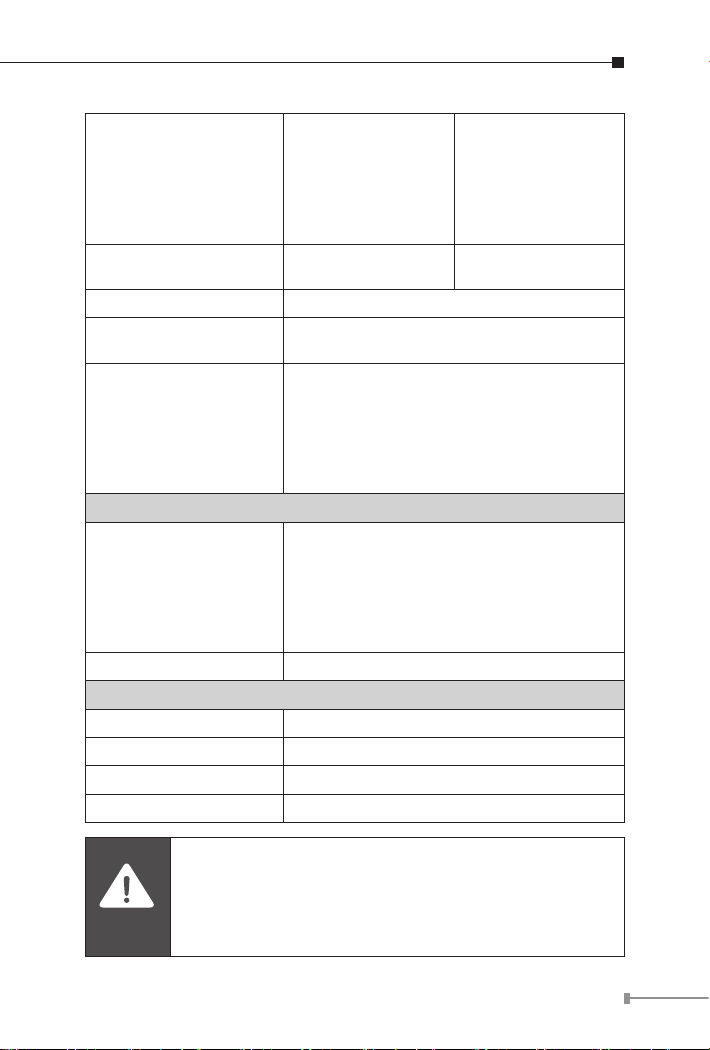
Product IPOE-171-60W IPOE-171-95W
Hardware Specications
Input Port
Interface
Network Cable*
LED Indicator
Data Rate 10/100/1000Mbps
Dimensions (W x D x H) 135 x 87.8 x 32 mm
Weight 430g 470g
Power Requirements DC 48~56V, 2A max. DC 24~48V, 5A max.
Unit Output Voltage DC 45~53V DC 54V
Power Consumption 75 watts max. 120 watts max.
No. of devices that can
be powered
Installation DIN-rail kit or wall-mount ear
Alarm
Enclosure IP30 slim type metal case
Power over Ethernet
PoE Standard IEEE 802.3af/at/bt Ultra PoE PSE
Output Port
Input Power
Terminal Block
1 x RJ45 STP
Data In
1 x RJ45 STP
PoE (Data + Power) Out
1
Twisted-pair cable up to 100 meters (328ft)
10BASE-T: 4-pair UTP Cat. 3, 4, 5, 5e, 6
100BASE-TX: 4-pair UTP Cat. 5, 5e, 6
1000BASE-T: 4-pair UTP Cat. 5e, 6
System: Power 1 (Green), Power 2 (Green),
Fault (Red)
PoE Port: PoE-in-Use x 1 (Orange)
PoE Usage: PoE Usage x 3 (Orange)
1
Provides one relay output for power failure
Alarm Relay current carry ability: 1A @ DC
24V
8
Page 9
DC 50~54V /
60-watt PoE via
PoE Power Output
Budget
PoE Power Output
PoE Power Supply Type End-span + Mid-span
Power Pin Assignment
PoE mode
Standards Conformance
Standards Compliance
Regulatory Compliance FCC Part 15 Class A, CE
Environment
Operating Temperature -40 ~ 75 degrees C
Storage Temperature -40 ~ 85 degrees C
Operating Humidity 5 ~ 90%, relative humidity, non-condensing
Storage Humidity 5 ~ 90%, relative humidity, non-condensing
4-pair
DC 48~49V /
30-watt PoE via
2-pair
Max. 60W@1 m
cable
Pair 1 End-span: 1/2(-), 3/6(+)
Pair 2 Mid-span: 4/5(+), 7/8(-)
Standard: To provide power to the PD
devices that follow the IEEE 802.3af/at/bt
standard.
Legacy: To provide power to the PD
devices that do not fully follow the IEEE
802.3af/at/bt standard.
IEEE 802.3 10BASE-T Ethernet
IEEE 802.3u 100BASE-TX Fast Ethernet
IEEE 802.3ab 1000BASE-T Gigabit Ethernet
IEEE 802.3bt 4-pair Power over Ethernet
IEEE 802.3at Power over Ethernet Plus
IEEE 802.3af Power over Ethernet
DC 54V / 95-watt
PoE via 4-pair
DC 54V / 30-watt
PoE via 2-pair
Max. 89.5W@1 m
cable
Caution
1. As IEEE 802.3bt device provides high power, please
use high-quality network cable and RJ45 connector.
2. The max. PoE output power depends on the cable
length, the quality of cable, and DC input voltage.
9
Page 10
4. Product Outlook
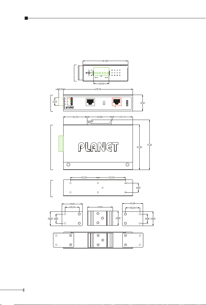
4.1 Physical Dimensions (example on IPOE-171A-95W)
Front View
Side View
Rear View
Mounting Kit
Top View
P1 P2 Fault
V2+ V2-
V1+ V1-
Input
PWR2
Fault
DC 24~48V
PWR1
10/100/1000T
Ethernet
Standard Legacy
PoE Power Usage
30W 60W 90W+
10/100/1000T
Ethernet+DC
802.3bt
PoE
IPOE-171-95W
in-Use
DIN-Rail Kit
Mounting Kit
Dimensions ( unit = mm )
Figure 1: IPOE-171-95W dimensions
10
Page 11
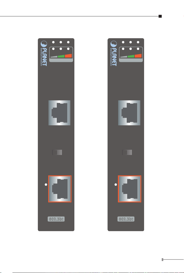
4.2 Product Outlook
P1 P2 Fault
20W 40W 60W+
PoE Power Usage
10/100/1000T
Ethernet
Standard Legacy
10/100/1000T
PoE
in-Use
P1 P2 Fault
30W 60W 90W+
PoE Power Usage
10/100/1000T
Ethernet
Standard Legacy
10/100/1000T
PoE
in-Use
Ethernet+DC
802.3bt
IPOE-171-60W
Ethernet+DC
802.3bt
IPOE-171-95W
Figure 2: IPOE-171-60W outlook Figure 3: IPOE-171-95W outlook
11
Page 12

IPOE-171-60W LED Indicators:
LED Color Function
P1 Green Lights to indicate power 1 has power.
P2 Green Lights to indicate power 2 has power.
FAULT Red
PoE-in-Use Orange
PoE Usage Orange
Lights to indicate either power 1 or power 2 has
no power.
Lights to indicate the device is providing PoE
power.
Monitor DC input voltage:
When user powers on POE-171-60W, the injector
will detect the DC input voltage and then PoE
Usage LED will ash three times.
20W: Flashing three times means the DC input
voltage is 48~50.9V.
40W: Flashing three times means the DC input
voltage is 51~52.9V.
60W+: Flashing three times means the DC input
voltage is 53~56V.
Monitor power usage:
20W:
1. Off to indicate the PoE usage is less than 9W.
2. Blinks to indicate that the PoE usage is around
10W to 19W.
3. Lights to indicate the PoE usage is around
20W to 29W.
40W:
1. Blinks to indicate that the PoE usage is around
30W to 39W.
2. Lights to indicate the PoE usage is around
40W to 49W.
60W+:
1. Blinks to indicate that the PoE usage is around
50W to 59W.
2. Lights to indicate the PoE usage is at the
maximum.
12
Page 13

IPOE-171-95W LED Indicators:
LED Color Function
P1 Green Lights to indicate power 1 has power.
P2 Green Lights to indicate power 2 has power.
FAULT Red
PoE-in-Use Orange
PoE Usage Orange
Lights to indicate either power 1 or power 2 has
no power.
Lights to indicate the device is providing PoE
power.
30W:
1. Off to indicate the PoE usage is less than 14W.
2. Blinks to indicate that the PoE usage is around
15W to 29W.
3. Lights to indicate the PoE usage is around
30W to 44W.
60W:
1. Blinks to indicate that the PoE usage is around
45W to 59W.
2. Lights to indicate the PoE usage is around
60W to 74W.
90W+:
1. Blinks to indicate that the PoE usage is around
75W to 89W.
2. Lights to indicate the PoE usage is at the
maximum.
13
Page 14
PoE Mode of IPOE-171 series:
PoE Mode Description
Standard
(Default)
The standard mode is chosen to provide power to the PD
devices that follow the IEEE 802.3af/at/bt standard.
The legacy mode is chosen to provide power to the PD
Legacy
devices that do not fully follow the IEEE 802.3af/at/bt
standard.
After changing the PoE mode, please power off and then
Note
on the PoE injector to make the change effective.
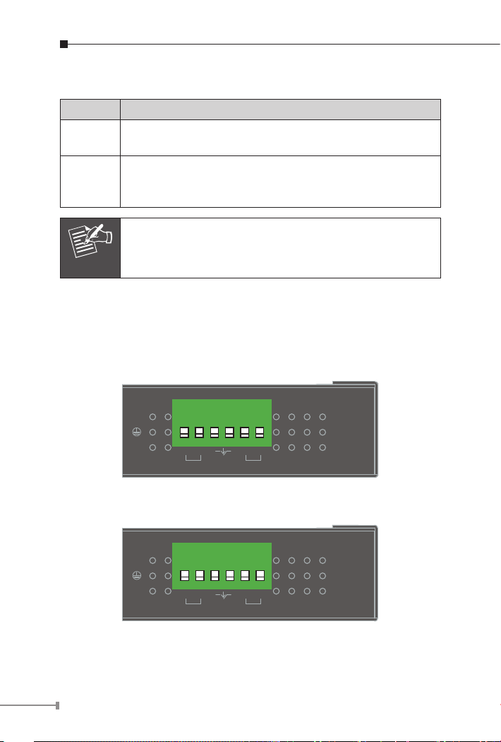
4.3 Industrial PoE+ Injector Upper Panel
The upper panel of the IPOE-171 series has one terminal block
connector where there are two DC power inputs.
1 2 3 4 5 6
Fault
V2+ V2-
PWR2
Input
DC 48~56V
V1+ V1-
PWR1
Figure 4: IPOE-171-60W upper panel.
1 2 3 4 5 6
Fault
V2+ V2-
PWR2
Input
DC 24~48V
V1+ V1-
PWR1
Figure 5: IPOE-171-95W upper panel.
14
Page 15
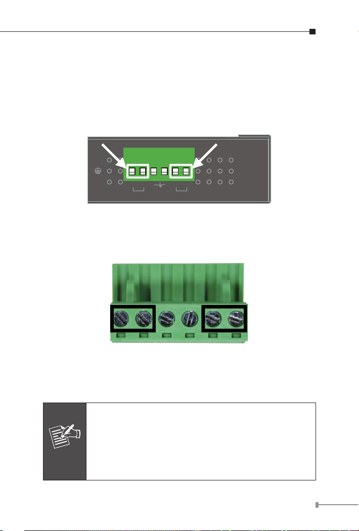
4.4 Wiring the Power Inputs
Note
The 6-contact terminal block connector on the top panel of the IPOE171 series is used for two DC redundant power inputs. Please follow
the steps below to insert the power wire.
Step 1: Insert Positive / Negative DC power wires into Contacts 1 and
2 for POWER 1, or 5 and 6 for POWER 2.
1 2 3 4 5 6
Fault
V2+ V2-
PWR2
Input
DC 48~56V
V1+ V1-
PWR1
Figure 6: Power input pins.
Step 2: Tighten the wire-clamp screws for preventing the wires from
loosening.
1 2 3 4 5 6
Power 1 Fault Power 2
+ - + -
Figure 7: PWR1 & PWR2 Pins of Terminal Block.
1. The wire gauge for the terminal block should be in the
range between 12 ~ 24 AWG.
2. As the DC input connector of the IPOE-171 series is
polarity protected, connecting Positive / Negative DC
power wires to the wrong pins will not damage the
unit.
15
Page 16
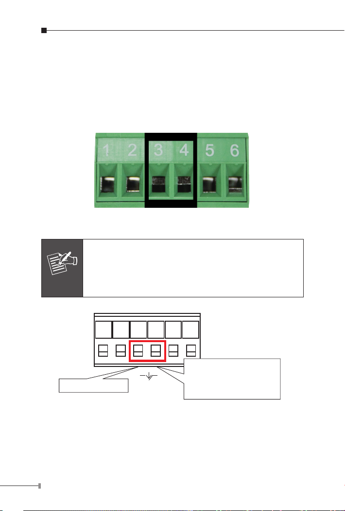
4.5 Wiring the Fault Alarm Contact
Note
The fault alarm contacts are in the middle of the terminal block
connector as the picture shows below. After inserting the wires,
the IPOE-171 series will detect the fault status of the power failure
and then form an open circuit. The following illustration shows an
application example for wiring the fault alarm contacts.
Figure 8: Fault Pin of Terminal Block.
1. The wire gauge for the terminal block should be in the
range between 12 ~ 24 AWG.
2. Alarm relay circuit accepts up to 24V, max. 1A
currents.
Fault Alarm Contacts
16
The Fault Alarm Contacts are
energized (CLOSE) for normal
operation and will OPEN when
Fault
failure occurs
Figure 9: Fault Alarm Contact
Page 17
5. Mounting Installation
This section describes how to install the industrial device and make
connections to it. Please read the following sections and perform the
procedures in the order being presented.
In the installation steps below, this manual uses PLANET
IGS-801 8-port Industrial Gigabit Switch as an example.
The steps for PLANET Industrial Slim-type Switch, Indus-
Note
trial Media/Serial Converter and Industrial PoE devices
are similar.
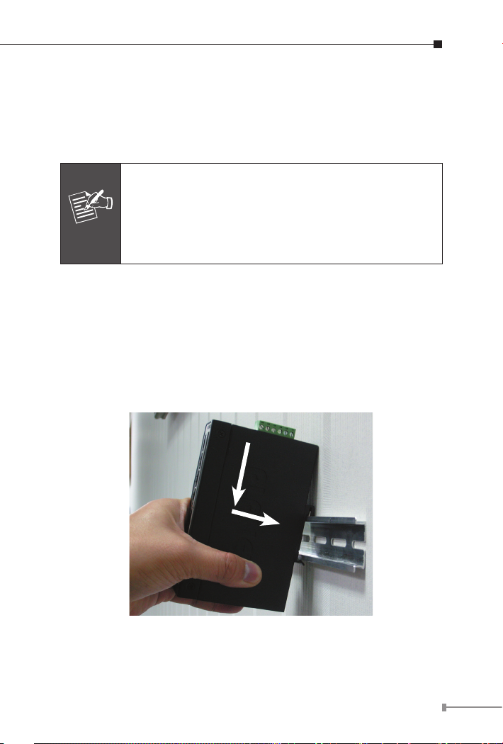
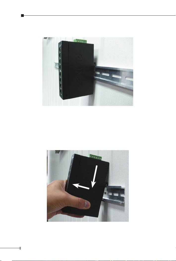
5.1 DIN-rail Mounting
The DIN-rail bracket is already screwed on the industrial device. Refer
to the following steps on how to install the industrial device:
Step 1: Lightly place the upper bracket found on the back of the
IPOE-171 into DIN rail and push the unit down till the lower
bracket is locked into the track.
1
2
Figure 10: Mounting industrial device on DIN rail.
17
Page 18
Step 2: The DIN-rail bracket should be tightly on the track.
Figure 11: DIN-rail mount industrial device
5.2 Removing Device from DIN Rail
Step 1: Please refer to following procedure to remove the industrial
device from the track.
1
2
Figure 12: Removing industrial device from DIN rail
18
Page 19

Step 2: Slightly push the unit down and lightly pull its bottom out to
completely remove it from the track.
5.3 Wall-mount Plate Mounting
To install the industrial device on the wall, please follow the instructions
described below.
Step 1: Unscrew the DIN-rail bracket to be removed from the
industrial device.
Step 2: Place the wall-mount plate on the rear panel of the industrial
device.
Figure 13: Attach brackets to the industrial device.
Step 3: Screw the wall-mount plate on the industrial device.
Step 4: Use the hook holes at the corners of the wall-mount plate to
hang the industrial device on the wall.
Step 5: To remove the wall-mount plate, reverse the above steps.
19
Page 20

6. Hardware Installation
The following section describes the hardware features of the IPOE-171
series. Before connecting any network device to it, please read this
chapter carefully.
6.1 Before Installation
Before your installation, it is recommended to check your network
environment. If there is any IEEE 802.3bt device that needs to be
powered on and works normally, the IPOE-171 series is the solution
that supplies power to this Ethernet device conveniently and easily. If
there is difculty in nding a power socket for the AC-DC connection
to your non-IEEE 802.3af/at/bt networked device, the IPOE-171 series
with POE-172S / IPOE-171S can supply DC power to this Ethernet
device conveniently and easily.
1. In the installation steps below, this manual uses the
IPOE-171-60W as an example. Except the input
voltage, the steps for the IPOE-171-95W are similar.
Note
6.2 IPOE-171-60W Installation
1. Connect the power ranging from 48V DC to 56V DC to the 6-pin
terminal block of the IPOE-171-60W. The power LED will be steadily
on.
2. Connect a standard Ethernet cable from an Ethernet switch or PC
workstation to “Ethernet” port of the IPOE-171-60W.
3. Connect the long cable to the “Ethernet+DC” port.
2. Note that the input power range of the IPOE-171-60W
is 48 ~ 56V DC and the input power range of IPOE171-95W is 24 ~ 48V DC.
20
Page 21
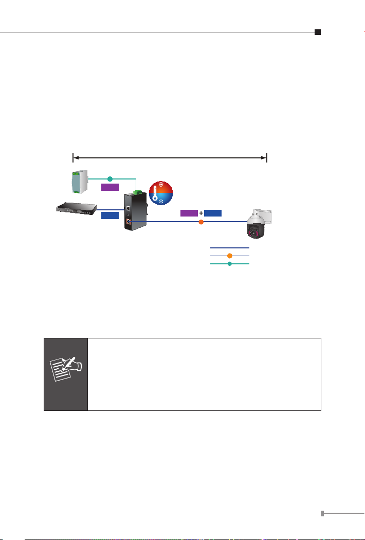
4. Connect with IEEE 802.3af/at/bt devices. Due to the capability of
IEEE 802.3af/at/bt Power over Ethernet, the IPOE-171-60W can
directly connect with any IEEE 802.3af/at/bt end-nodes, such as
PTZ (Pan, Tilt & Zoom) IP cameras, PTZ speed dome cameras, color
touch screens, Voice over IP (VoIP) telephones and multi-channel
wireless LAN access points which support IEEE 802.3af/at/bt In-line
Power over Ethernet port.
100 meters
DC Input
Power
Supply
Industrial
Switch
DC
Power
Data
IPOE-171 Series
75
℃
-40
℃
Power
Data
PoE
PoE
DC
PoE PTZ
IP Camera
1000BASE-T UTP
1000BASE-T UTP with PoE
Power Line (DC)
Figure 14: Connecting architecture with IEEE 802.3af/at/bt device
Once the IPOE-171-60W detects the existence of an IEEE 802.3af/at/bt
device, the PoE-in-Use LED indicator will be steadily on to show it is
providing power.
1. According to IEEE 802.3af/at/bt Power over Ethernet,
the IPOE-171-60W will not inject power to the cable if
not connected to IEEE 802.3af/at/bt device.
Note
2. Depending on the length of cable, the PoE power
which PD receives is different.
21
Page 22
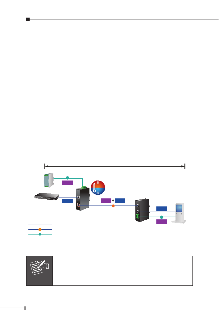
6.3 IPOE-171-60W and IPOE-171S Installation
1. Adjust proper DC power output and connect wire from “Power
Output” of IPOE-171S to remote device.
2. Connect the power ranging from 48V DC to 56V DC to the 6-pin
terminal block of the IPOE-171-60W. The power LED will be steadily
on.
3. Connect a standard Ethernet cable from an Ethernet switch or PC
workstation to the “Ethernet” port of the IPOE-171-60W.
4. Connect a standard Ethernet cable from “Ethernet+DC” port of the
IPOE-171-60W to “PoE In” port of the IPOE-171S. The “PWR” and
“60W” LEDs of the IPOE-171S and the “PoE-in-Use” of the IPOE171-60W will light up continuously.
5. Connect a standard Ethernet cable from the “Ethernet” port of the
IPOE-171S to the remote Ethernet device.
6. The remote device will be turned on and connected.
100 meters
DC Input
Power
Supply
Industrial
Switch
PoE
DC
DC
Power
Data
IPOE-171 Series
1000BASE-T UTP
1000BASE-T UTP with PoE
Power Line (DC)
75
℃
-40
℃
Power
PoE
Data
Industrial 802.3bt
PoE Splitter
12V/24V DC Output
Data
DC
Power
Digital Signage
Figure 15: Connected Architecture of IPOE-171-60W and IPOE-171S
Please ensure the IPOE-171S output voltage is correct
Note
before applying power to remote device.
22
Page 23

6.4 IPOE-171-60W and IPOE-E172 Installation
1. Connect the power ranging from 48V DC to 56V DC to the 6-pin
terminal block of the IPOE-171-60W. The power LED will be steadily
on.
2. Connect a standard Ethernet cable from an Ethernet switch or PC
workstation to the "Ethernet" port of the IPOE-171-60W.
3. Connect a standard Ethernet cable from the “Ethernet+DC” port of
the IPOE-171-60W to the “PoE IN” port of the IPOE-E172.
4. The IPOE-171-60W delivers both Ethernet data and PoE power over
UTP cable to the IPOE-E172 and the “POE-in-Use” LED of IPOE171-60W and “PWR” LED of IPOE-E172 will light up continuously.
5. Connect the additional standard Ethernet cable that will be used for
connecting to the remote powered device (PD) to the “PoE Out”
port of the IPOE-E172.
6. The “PoE Out” port is also the power injectors which transmit DC
voltage to the standard network cable and transfer data and power
simultaneously between the IPOE-172 and PD.
7. Once the IPOE-E172 detects the existence of an IEEE 802.3af/at/bt
device, the “PoE-in-Use” LED indicator will be steadily ON to show
it is providing power.
23
Page 24
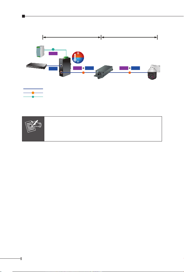
Power
Supply
100 meters 100 meters
DC Input
DC
Power
75
℃
-40
℃
Industrial
Switch
PoE
DC
Data
IPOE-171 Series
1000BASE-T UTP
1000BASE-T UTP with PoE
Power Line (DC)
Power
Data
PoE
Industrial 802.3bt
PoE Extender
Power
Data
PoE
Figure 16: Connected Architecture of IPOE-171-60W and IPOE-E172
Depending on the length of cable, the PoE power which
Note
PD receives is different.
PoE PTZ
IP Camera
24
Page 25

7. Customer Support
Thank you for purchasing PLANET products. You can browse our online
FAQ resource at the PLANET Web site rst to check if it could solve
your issue. If you need more support information, please contact
PLANET PoE support team.
PLANET online FAQs:
http://www.planet.com.tw/en/support/faq?method=category&c1=2
PoE support team mail address:
support_poe@planet.com.tw
Copyright © PLANET Technology Corp. 2018.
Contents are subject to revision without prior notice.
PLANET is a registered trademark of PLANET Technology Corp. All other trademarks
belong to their respective owners.
25
Page 26

EC Declaration of Conformity
For the following equipment:
*Type of Product: Industrial Single-Port 10/100/1000Mbps 802.3bt PoE Injector
*Model Number: IPOE-171-60W/IPOE-171-95W
* Produced by:
Manufacturer‘s Name : Planet Technology Corp.
Manufacturer‘s Address: 10F., No.96, Minquan Rd., Xindian Dist., New Taipei City 231, Taiwan
is herewith confirmed to comply with the requirements set out in the Council Directive on the Approximation of
the Laws of the Member States relating to Electromagnetic Compatibility Directive on 2014/30/EU.
For the evaluation regarding the EMC, the following standards were applied:
EN55032
EN 61000-3-2
EN55024 (2010+A1:2015)
IEC 61000-4-2
IEC 61000-4-3
IEC 61000-4-4
IEC 61000-4-5
IEC 61000-4-6
IEC 61000-4-8
IEC 61000-4-11
Responsible for marking this declaration if the:
Manufacturer Authorized representative established within the EU
Authorized representative established within the EU (if applicable):
Company Name: Planet Technology Corp.
Company Address: 10F., No.96, Minquan Rd., Xindian Dist., New Taipei City 231, Taiwan
Person responsible for making this declaration
Name, Surname Jonas Yang
Position / Title : Product Manager
Tai w an
Place
20 Apr., 2018
Date Legal Signature
(2015)
(2014)
(2013) EN 61000-3-3
(2008)
(2006+A1:2007+A2:2010)
(2012)
(2014)
(2013)
(2009)
(2004)
PLANET TECHNOLOGY CORPORATION
10F., No.96, Minquan Rd., Xindian Dist., New Taipei City, Taiwan, R.O.C. Tel:886-2-2219-9518 Fax:886-2-2219-9528
e-mail: sales@planet.com.tw http://www.planet.com.tw
Page 27

Page 28

 Loading...