

Page 1

Relay
™
3000/4000
User Guide
International English Edition
SV63138 Rev. A
August 1, 2015
Document Inserting Systems with
Touch Screen and Barcode Scanning
Shipping & Mailing
Inserter
Page 2

Statement of FCC Compliance
This equipment has been tested and found to comply with the limits for a Class A
digital device, pursuant to part 15 of the FCC rules. These limits are designed to
provide reasonable protection against interference when the equipment is operated
in a commercial environment. This equipment generates, uses, and can radiate radio
frequency energy and, if not installed and used in accordance with the instruction
manual, may cause interference to radio communications. Operation of this equipment
in a residential area is likely to cause interference, in which case the user will be
required to correct the interference at his own expense. Use only a shielded interface
cable to operate this equipment with a printer or other peripheral device.
CAUTION: Changes or modifications to this equipment not expressly approved by
the party responsible for compliance (Pitney Bowes) could void the user’s authority
to operate the equipment.
SV63138 Rev. A August 1, 2015
©2006, 2015 Pitney Bowes Inc. All rights reserved. This guide may not be
reproduced in whole or in part in any fashion or stored in a retrieval system of
any type or transmitted by any means, electronically or mechanically, without
the express, written permission of Pitney Bowes.
We have made every reasonable effort to ensure the accuracy and usefulness
of this manual; however, we cannot assume responsibility for errors or omissions
or liability for the misuse or misapplication of our products.
Due to our continuing program of product improvement, equipment and
material specications as well as performance features are subject to change
without notice. Your inserter system may not have some of the features
described in this book.
E-Z Seal is a registered trademark of Pitney Bowes Inc. ENERGY STAR is a
registered trademark of the United States Environmental Protection Agency.
It is certified that the equipment complies with all applicable Directives
of the European Union. The touch screen and main inserting system
contain a radio frequency transmitting device that is in compliance with
the European Union’s Directive 1999/5/EC on Radio Equipment and
Telecommunications Terminal Equipment and the mutual recognition of
their conformity.
LED SAFETY
LED emission according to EN 62471
Relay 3000/4000 is UL approved (US) and CUL approved (Canada).
Page 3

Table of Contents
iSV63138 Rev. A
Safety ................................................................................... v
Chapter 1 System Overview
Relay Inserter Introduction ................................................1-3
Inserter Component Identification ...................................... 1-4
Touch Screen Display Identification ...................................1-6
Control Panel Icons ...........................................................1-8
Turn the Touch Screen On/Off ......................................... 1-10
Use the Touch Screen Keyboard ..................................... 1-11
Change the Display Language ........................................ 1-11
Touch Screen Usernames and Passwords ......................1-12
Rename Default Usernames .................................... 1-12
Change an Existing Operator Password .................. 1-13
Recover an Existing Operator Password ................. 1-13
Rename an Existing Default Job .....................................1-14
Inserter Control Reports (on the Touch Screen) .............. 1-15
Report Data .............................................................. 1-15
Access Reports ........................................................ 1-16
Archive Reports ....................................................... 1-17
Print Reports ............................................................ 1-17
Chapter 2 Program a Job
Navigate Using the Touch Screen .....................................2-3
Scanning and Non-Scanning Jobs ............................. 2-4
Program a Job ...................................................................2-5
Log In ......................................................................... 2-5
Enter Supervisor Access Code .................................. 2-5
Select the Job Number (New or Existing Job) ........... 2-5
Program a Scanning Job ........................................... 2-6
Program a Non-Scanning Job .................................. 2-14
Modify an Existing Job ..................................................... 2-23
Delete a Job ....................................................................2-23
Page 4

Table of Contents
ii SV63138 Rev. A
Chapter 3 Run a Job
Run a Job ..........................................................................3-3
Verify the Inserter Has Power ............................................ 3-4
Turn On the Touch Screen .................................................3-4
Log In .................................................................................3-4
Select a Job ............................................................... 3-5
Manual Feed Jobs .............................................................3-6
Load Material .....................................................................3-7
Adjust and Load the Sheet Feeders .......................... 3-7
Adjust and Load the Envelope Feeder ....................... 3-8
Adjust and Load the Insert Feeder ........................... 3-10
Run a Trial Piece .............................................................3-12
Trial Pieces and Linked Feeding .............................. 3-12
Material Changes or Double Detect Issues
During Operation ................................................. 3-12
Start and Stop the Inserter ..............................................3-13
Fill the Sealer ...................................................................3-14
Adjust the Stacker ...........................................................3-14
Chapter 4 OMR Scanning
Optical Mark Recognition (OMR) ....................................... 4-3
Accuracy .................................................................... 4-3
OMR and Feeders on the Inserter ..................................... 4-3
OMR Scanning Types ........................................................4-4
Basic OMR ................................................................. 4-4
Enhanced OMR ......................................................... 4-4
OMR Mark Positions ..........................................................4-4
OMR Specifications ...........................................................4-5
Standard OMR Positions ........................................... 4-6
Offset OMR Positions ................................................. 4-7
Available OMR Marks .......................................................4-8
Benchmark ................................................................. 4-8
Safety ......................................................................... 4-8
End-of-Collation (EOC) .............................................. 4-8
Beginning-of-Collation (BOC) .................................... 4-8
Page 5

Table of Contents
iiiSV63138 Rev. A
Parity .......................................................................... 4-8
Re-timing Mark ........................................................... 4-8
Select Feed (SF1, SF2) ............................................. 4-9
Auto Batch ................................................................. 4-9
Wrap Around Sequence (WAS1, WAS2, WAS3) ....... 4-9
OMR Mark Grouping .......................................................4-10
C-Fold and Double-Fold Jobs .................................. 4-10
Z-Fold and Single-Fold Jobs .....................................4-11
Adjust the OMR Scanner ................................................. 4-12
OMR Troubleshooting ......................................................4-14
Error Recovery for OMR Jobs .................................. 4-14
Error Recovery for Accumulation Jobs ..................... 4-14
Error Recovery for Empty Feeders .......................... 4-14
OMR Error Messages ......................................................4-15
Chapter 5 Barcode Scanning
Barcode Scanning .............................................................5-3
How Barcode Scanning Works .................................. 5-3
1D and 2D Barcode Scanning ................................... 5-3
Jobs with Barcode Scanning ...................................... 5-4
Barcode Options ................................................................5-4
Basic Barcode Reading ............................................. 5-4
Enhanced Barcode Reading ...................................... 5-4
Barcode Placement Specifications ....................................5-5
Barcode Placement Areas ........................................ 5-5
Barcode Zones - Clear and Blank .............................. 5-7
2D Barcode Camera Setup ...............................................5-8
Turn On the 2D Barcode Camera .............................. 5-8
Adjust the Position of the 2D Barcode Camera ......... 5-9
2D Barcode Scanning Final Checklist .............................5-10
Barcode Error Messages ................................................. 5-11
2D Barcode Specifications ..............................................5-12
Paper Specifications ............................................... 5-12
2D Barcode Specifications ....................................... 5-12
Page 6

Table of Contents
iv SV63138 Rev. A
Chapter 6 Clear Material
Clear Material ....................................................................6-3
Access Areas of the Inserter for Jam Removal .................6-3
Sheet Feeders Trays - Remove and Replace ............ 6-3
Fold Plates - Remove and Replace ........................... 6-4
Insert Tray - Remove and Replace ............................ 6-4
Access the Carriage Assembly .................................. 6-4
Access to Envelope Feeder Area ............................... 6-5
Access the Envelope Exit Area .................................. 6-5
Access the Envelope Inserting/Sealing Area ............. 6-6
Access to the Sheet Feed Area ................................. 6-6
Chapter 7 Troubleshooting and Error Messages
General Troubleshooting ...................................................7-3
Changing the Sealer Unit Felts .................................. 7-7
Error Messages .................................................................7-9
Chapter 8 Material Specifications
Material Specifications .......................................................8-3
Inserter Specifications .......................................................8-7
Service ...............................................................................8-8
Page 7

Safety
v
SV63138 Rev. A
Safety Information
Follow these precautions whenever you use your inserting system:
• Read all instructions before you attempt to operate the system.
• Use this equipment only for its intended purpose.
• Place the system close to an easily accessible wall outlet.
• Place the system in an accessible location to allow for proper venting
of the equipment and to facilitate servicing.
• Use the AC power adapter included with this device. Third party
adapters may damage the device.
• Plug the AC adapter directly into a properly grounded wall outlet
located near the equipment and easily accessible. Failure to properly
ground the machine can result in severe personal injury and/or fire.
• The AC adapter/power cord is the primary means to disconnect this
device from the AC supply.
• DO NOT use a wall outlet controlled by a wall switch or one that is
shared with other equipment.
• DO NOT use an adapter plug on the line cord or wall outlet.
• DO NOT remove the ground pin from the line cord.
• DO NOT route the AC adapter power cord over sharp edges or trap it
between furniture. Make sure there is no strain on the power cord.
• If the unit becomes damaged, unplug it from the wall.
• Keep fingers, long hair, jewelry and loose clothing away from moving
parts at all times.
• Avoid touching moving parts or materials while the machine is in
use. Before clearing a jam, be sure machine mechanisms come to a
complete stop.
• Remove jammed material gently and carefully.
• DO NOT remove covers. Covers enclose hazardous parts that should
only be accessed by properly trained service personnel.
• DO NOT place lighted candles, cigarettes, cigars, etc., on the system.
• To prevent overheating, do not cover vent openings.
• Use only approved supplies.
• Improper storage and use of aerosol dusters or flammable aerosol
dusters can cause an explosive-like condition that could result in
personal injury and/or property damage.
• Never use aerosol dusters labeled flammable and always read
instructions and safety precautions on the duster container label.
Page 8

Safety
vi SV63138 Rev. A
• Operation of this equipment without periodic maintenance will inhibit
optimum operating performance and could cause the equipment to
malfunction.
• Always follow specific occupational safety and health standards for
your workplace.
• To reduce the risk of fire or electrical shock, DO NOT attempt to
remove covers or disassemble the control panel or its base. The
cabinet encloses hazardous parts.
• Before operating the main inserting machine with this device, make
sure the machine has been properly prepared and that any other
personnel in the area are standing clear of the inserter.
• Immediately report to service any damaged or non-functioning
components that renders the unit unsafe.
• Contact your system supplier for the following:
- Supplies
- Material Safety Data Sheets
- If you should damage the unit
- Required maintenance service schedule
If Your Stacker has an AC Adapter:
• Use the AC power adapter included with this device. Third party
adapters may damage the device
• To protect against electrical shock, plug the AC adapter power cord
into a properly grounded wall outlet.
• DO NOT route the power cord for the AC adapter over sharp edges or
trap it between it between pieces of furniture. Make sure there is no
strain on the power cord.
IMPORTANT: Some of the inserter features and options covered in this
content may not be available on your inserter.
Page 9

SV63138 Rev A
1 • System Overview
Contents
Relay Inserter Introduction .........................................1-3
Inserter Component Identification...............................1-4
Touch Screen Display Identification............................1-6
Control Panel Icons ....................................................1-8
Turn the Touch Screen On/Off .................................... 1-10
Use the Touch Screen Keyboard ................................ 1-11
Change the Display Language ...................................1-11
Touch Screen Usernames and Passwords.................1-12
Rename or Create an Operator Username ......... 1-12
Change or Create an Existing
Operator Password ........................................ 1-12
Recover an Existing Operator Password ............ 1-13
Change a Job Name...................................................1-13
Inserter Control Reports (on the Touch Screen) ......... 1-14
Report Data ......................................................... 1-14
Access Reports ................................................... 1-15
Archive Reports .................................................. 1-16
Print Reports ....................................................... 1-16
Page 10

This page is intentionally blank.
Page 11
1 ● System Overview
1-3SV63138 Rev. A
Relay Inserter Introduction
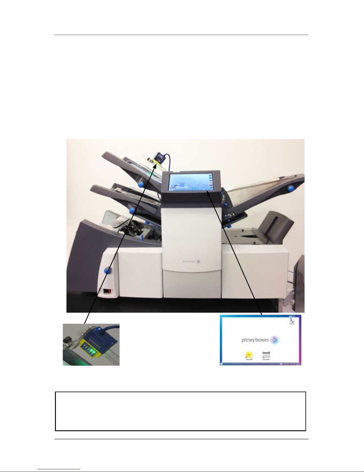
The Relay 3000 and 4000 Inserters offer touch screen functionality and
barcode scanning. The touch screen is standard on the Relay 4000 and
an option for the Relay 3000. The touch screen is necessary for barcode
scanning, which is an option for both systems.
Touch screen technology makes it easy to set up jobs and use the inserter.
Enhanced barcode scanning decodes barcode information and enables
the inserter to maintain the integrity of your mailpiece.
NOTE: The Relay Inserter touchscreen is a WiFi enabled device. If clients
choose to utilize this network connection it is the responsibility of the client
to ensure that the settings adhere to their IT department standards.
Touch Screen Control
Barcode Scanning
Page 12
1 ● System Overview
1-4 SV63138 Rev. A
1
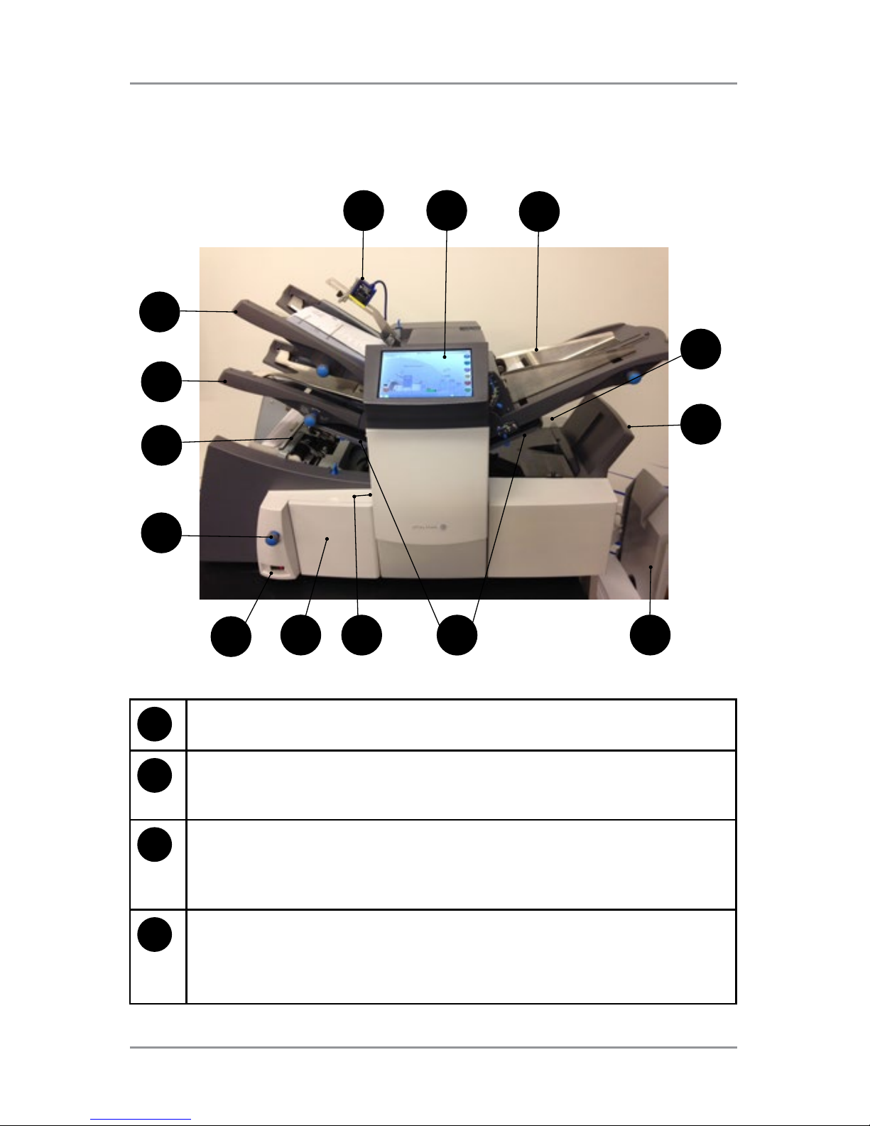
2D Camera — Converts barcode characters into mailpiece
processing information.
2
Touch Screen Display — Use this interface to enter commands,
setup jobs, and change settings. Symbols and icons on the display
show the system status.
3
Insert Feeder — Use this feeder to add additional inserts to your
envelope. Material fed from this feeder cannot be folded by the
inserter. However, this feeder is especially suited to feeding prefolded or thicker inserts.
4
Sealer Bottle — The sealer bottle is located on the rear of the
inserter on the right side. It is under a hinged cover, labeled with
the sealer icon. The sealer bottle provides sealing solution to the
envelope sealer.
Inserter Component Identification
1
2
3
4
5
6
78
12
13
14
11
9
10
Page 13

1 ● System Overview
1-5SV63138 Rev. A
5
Envelope Inverter - Transports the envelope into the stacker face up.
6
Drop Stacker or Output Device — located at the exit of the inserter,
this device collects finished mailpieces. This device can be latched
against the inserter when not in use. Alternatively, a range of power
stackers are available which offer greater capacity than the standard
drop stacker.
7
Fold Plate 1 and 2 — They create the desired fold in material
fed
from the sheet feeder(s). The fold plates are automatically set from
the control panel.
8
Measuring Scale — The scale is located on the left side of the
inserter near the sheet feeders; used as an aid in measuring material
and envelopes.
9
Manual Advance Knob — The knob is located under a cover on
the front, left, lower corner of the inserter. Use it to turn the inserter
mechanisms by hand to help clear a material.
10
Power Switch — This switch turns the inserter on and off.
11
Side Guide Adjustment Knob — Use this knob to adjust the side
guides on the envelope feeder.
12
Envelope Feeder — Feeds envelopes into the inserting area where
they are filled with material requested from the other feeder(s).
13
Sheet Feeder 2 — Feeds material that requires folding. Its functions
are similar to those of sheet feeder 1, but the manual feed option is
NOT available from this feeder.
14
Sheet Feeder 1 — this feeder is intended for feeding material that
requires folding.
In addition, you can set sheet feeder 1 to Manual Feed. In this mode,
you can run stapled sets of up to five sheets. The inserter waits for
you to feed each set by hand into sheet feeder 1 before folding and
inserting the set automatically.
Page 14
1 ● System Overview
1-6 SV63138 Rev. A
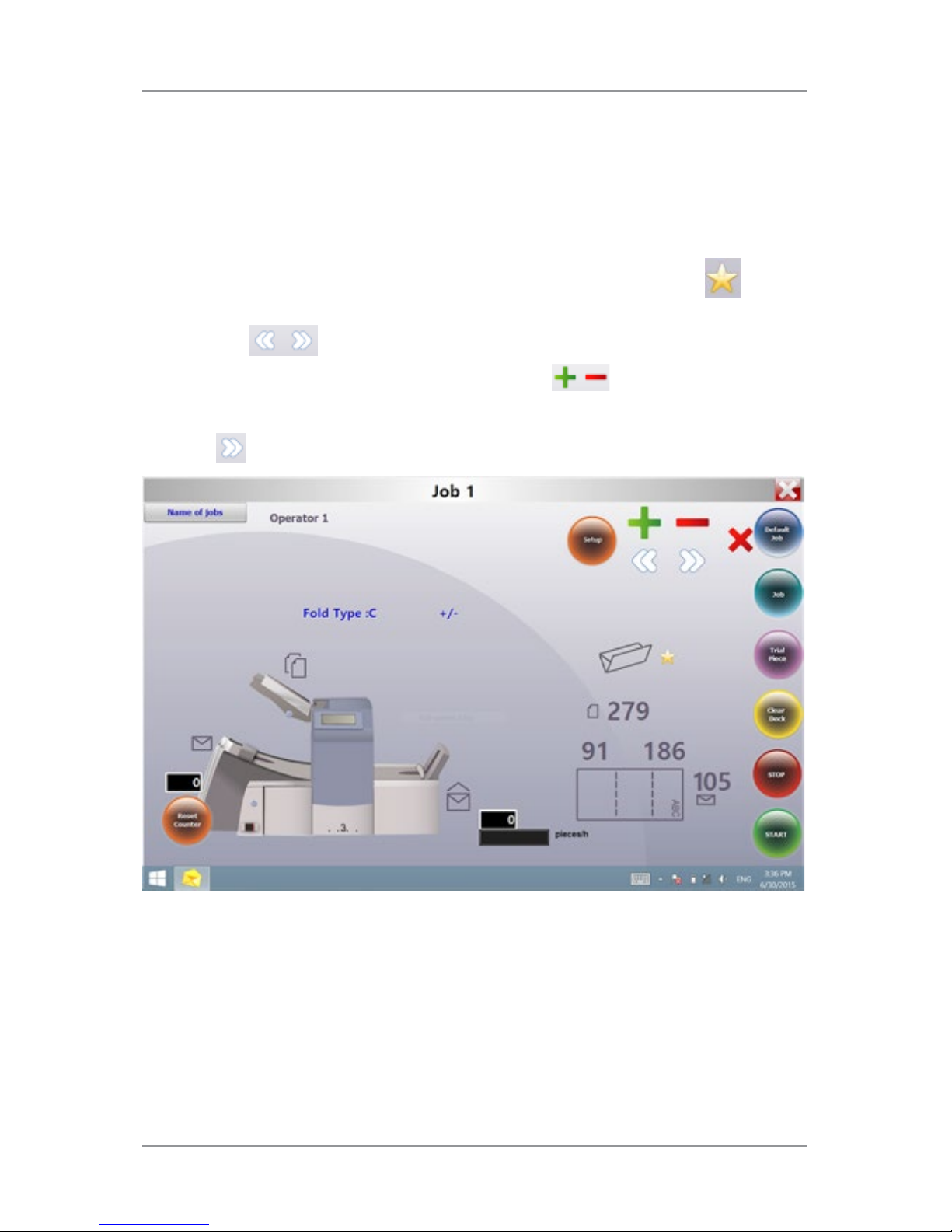
Touch Screen Display Identification
6
2
7
8
9
10
11
20
3
4
5
15
1
14 13
12
16
1
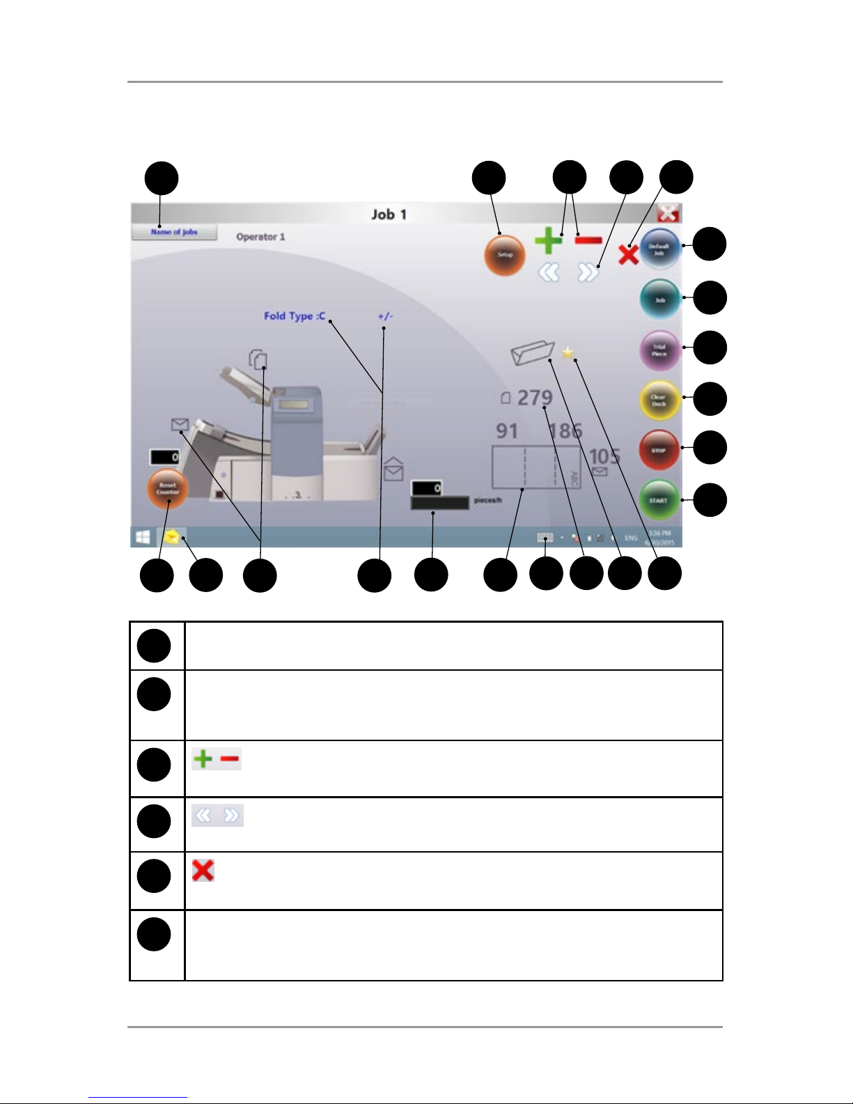
Name of Jobs - Accesses the change job name screen.
2
Setup - Tap to access setup mode to program jobs into system
memory and change options in existing jobs. (Supervisor function;
setup mode only)
3
- Tap these icons to scroll through available options for job
settings. (Supervisor function; setup mode only)
4
- Tap these icons to scroll through available job settings.
(Supervisor function; setup mode only)
5
- Tap to delete a programmed job from the inserter memory.
(Supervisor function; setup mode only)
6
Default Job - Tap to return inserter to its default or standard
settings, which are pre-configured from the factory. A Pitney
Bowes Service Representative can change these settings.
1819
17
21
Page 15

1 ● System Overview
1-7SV63138 Rev. A
7
Job - Tap repeatedly to scroll through programmed jobs that
are stored in the inserter and select a job you want to run. The
inserter can store up to 21 jobs (including one default job).
8
Trial Piece - Tap to run a single test piece to check inserter setup.
You must run a trial piece before you begin automatic operation
using the Start button. If you use double detection, the inserter
sets itself automatically as it runs the trial piece. The trial piece
envelope will be unsealed and counted as one item.
9
Clear Deck - Tap to jog material through and out of the inserter.
Also use it to clear the inserter and make it ready for automatic
operation after a stoppage has occurred.
10
Stop - Tap to stop automatic operation at the end of the next
cycle
11
Start - Tap to start automatic operation.
12
Gold Star - Helps guide you through the job settings by
displaying next to the icon of the setting you are programming /
changing.
13
Fold Type Icon - Represents the selected fold option.
14
Sheet Length Icon - Indicates in millimeters the length of the
unfolded sheet.
15
Keyboard Icon - Tap to display a full keyboard displays on the
lower half of the touch screen.
16
Letter Fold Icon - Indicates in millimeters the fold areas for the
selected fold type.
17
Counter - Shows the number of mailpieces produced per hour.
18
Option Icons - Indicate there are available options within the
selected setting.
19
Symbol Icons - Example of an icon that represents the contents
of the feeder (double detect and envelope feed in this example).
20
Insert Control Icon - Tap to return display to opening screen.
21
Reset Counter - tap to reset the item or batch counter.
Page 16
1 ● System Overview
1-8 SV63138 Rev. A
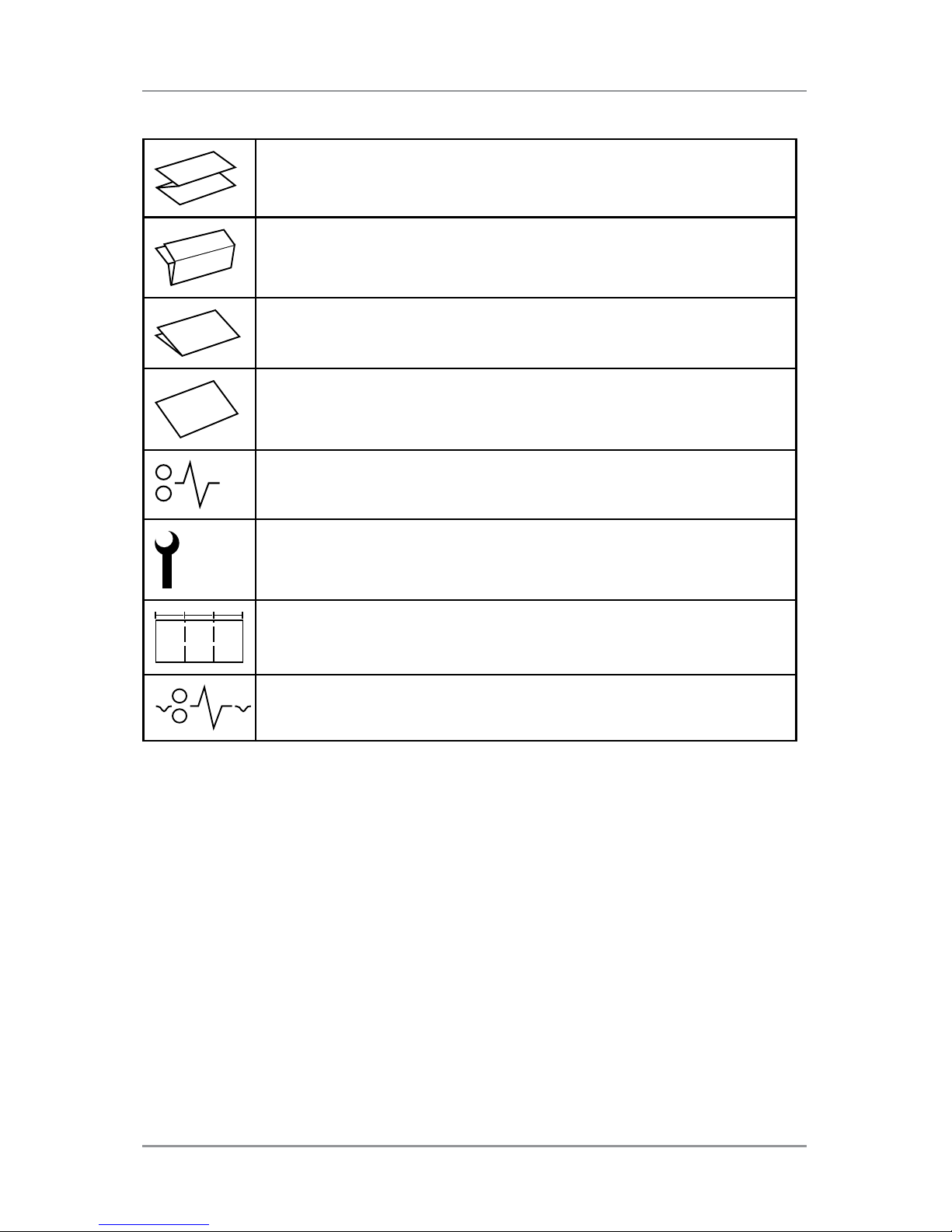
Control Panel Icons
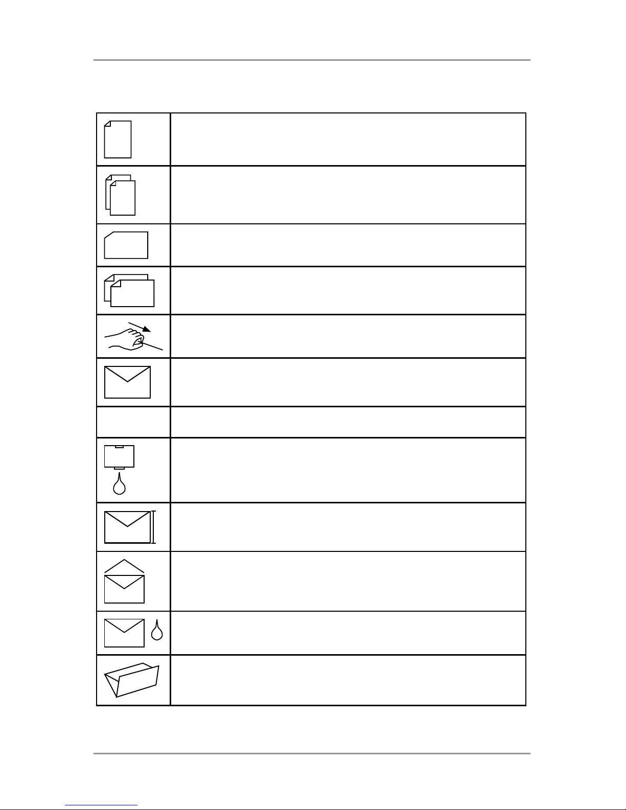
Used on sheet feeders to signify that the feeder is on
without double detection.
Used on sheet feeders to signify that the feeder is on with
double detection.
Used on insert feeder to signify that the feeder is on
without double detection.
Used on insert feeder to signify that the feeder is on with
double detection.
Used on sheet feeder 1 to signify that the feeder is set for
manual feed.
Indicates the setting (from 1 to 5) of the envelope stop.
. . 3 . .
Indicates that the sealer bottle needs refilling.
Indicates the envelope depth.
Indicates the sealer unit is off (envelopes not sealed).
Indicates the sealer unit is off (envelopes not sealed).
Indicates the sealer unit is on (automatic envelope sealing)
Indicates a C (letter) fold is selected
Page 17
1 ● System Overview
1-9SV63138 Rev. A
Indicates a Z (accordion fold) is selected
Indicates a double fold is selected
Indicates a single fold is selected
Indicates a no-fold insert operation
Indicates a material stoppage. The position of this symbol
in the display indicates where the stoppage has occurred.
Call Pitney Bowes for service
ABC
Indicates the paper size, address orientation and fold(s)
set for sheet feeder
Indicates a material stoppage in a downstream device,
such as a power stacker.
Page 18
1 ● System Overview
1-10 SV63138 Rev. A
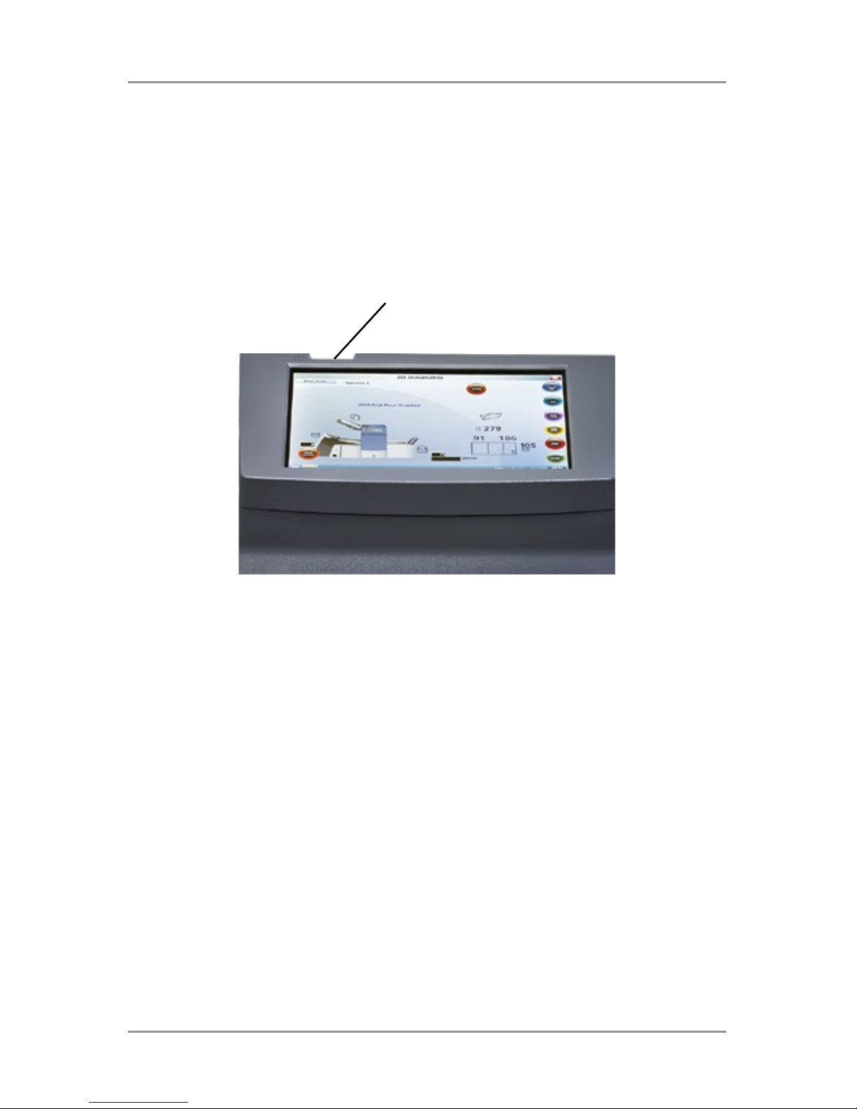
Turn the Touch Screen On/Off
1. Verify the inserter is powered up before you turn on the touch screen.
2. Press and hold the ON/OFF power button for a few seconds. The
power button is located on the top eft frame of the touch screen.
NOTE: If the touch screen is in sleep mode, press the ON/OFF button.
Touch Screen ON/OFF Power Button
Page 19
1 ● System Overview
1-11SV63138 Rev. A
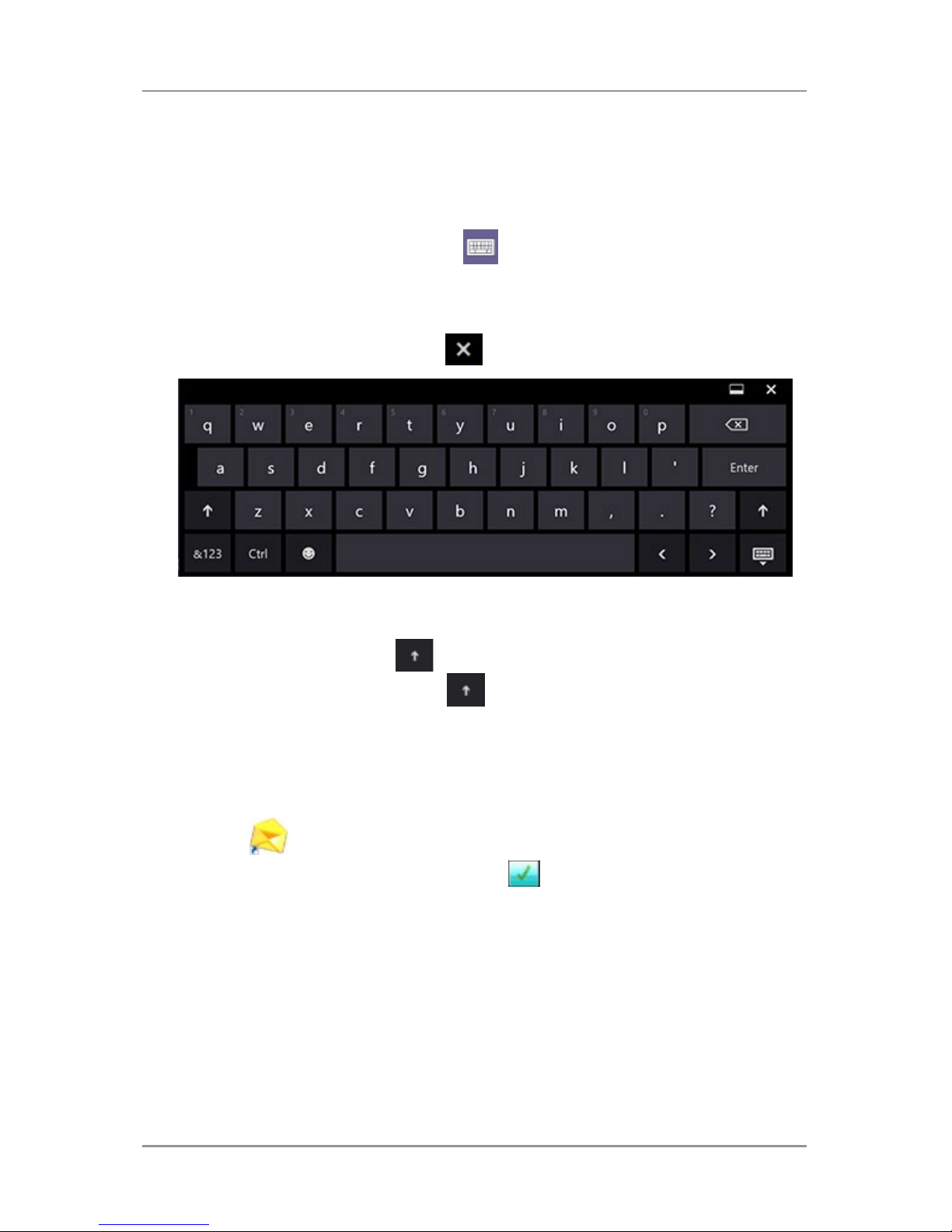
Use the Touch Screen Keyboard
NOTE: If the Windows task bar does not show along the bottom of the display,
swipe your finger down toward the bottom of the screen.
1. To launch the keyboard, tap the icon on the task bar in the lower
right corner of the display.
2. Tap the desired characters to enter information.
3. To close the keyboard tap the
in the upper right corner.
Capital Letters
• For single caps tap the
key once.
• To turn Caps Lock on tap the
key twice.
Change the Display Language
To change the language on the touch screen display:
1. Tap the icon on the opening screen.
2. When the Operator List displays, tap .
3. Select Language>Program from the menu bar. A screen opens
displaying country flags associated with available languages.
4. Tap the flag that represents the language you want to display on the
touch screen. (This screen automatically closes and the display is now
in the newly selected language.)
Page 20

1 ● System Overview
1-12 SV63138 Rev. A
Touch Screen Usernames and Passwords
Operators and Supervisors can rename operator usernames and change
operator passwords.
NOTE: The customer service representative who installs your system
provides the Supervisor password. Supervisor passwords cannot be
changed.
Rename Default Operator Usernames
Each operator requires a unique username. This procedure can be used
to rename an existing default operator username to a specific operator
username. A maximum of 10 operators can be programmed into the touch
screen.
1. Tap the icon twice.
2. When the Operator List displays select a default Operator to rename
(typically indicated as Operator 1 – Operator 10).
3. To launch the keyboard, tap the icon (bottom right corner of the
screen) and enter either the Supervisor or Operator password in the
field. (DO NOT tap .)
4. Select File>Operators>Change from the menu bar.
5. Use the touch screen keyboard to enter the new operator name.
6. Tap .
Page 21

1 ● System Overview
1-13SV63138 Rev. A
Change an Existing Operator Password
This procedure can be used to change an existing operator password.
1. Tap the icon twice.
2. When the Operator List displays select an Operator username and
tap
.
3. To launch the keyboard, tap the icon on the bottom right corner of
the screen and enter the Operator password in the field. (DO NOT tap
.)
4. Select File>Password>Change from the menu bar.
5. Use the touch screen keyboard to enter the new password; re-enter
the password to confirm.
6. Tap .
7. Tap .
Recover an Existing Operator Password
This activity requires Supervisor level access.
1. Tap the icon twice.
2. When the Operator List displays, select the Operator name
associated with the lost password and tap .
3. Tap the touch screen keyboard and enter the Supervisor password
(71) in the field. (DO NOT tap .)
4. Select File>Password>Recover from the menu bar. The recovered
password displays in the dialog box. (Be sure to record the password
for future reference.)
5. Tap OK to close the dialog box.
6. Type the recovered password into the password field and tap .
Page 22

1 ● System Overview
1-14 SV63138 Rev. A
Rename an Existing or Default Job
When a new job is created, a new name can be assigned to a default job.
Operators and Supervisors can rename a job.
1. Tap the icon twice.
2. When the Operator List displays select an Operator and tap .
3. To launch the keyboard, tap the icon on the bottom right corner of
the screen and enter the Operator password in the field.
4. Tap .
5. At the main control screen, tap the Name of jobs button in the upper
left corner of the display.
6. Highlight a job in the Name of jobs list and tap Change.
7. Using the touch screen keyboard enter the new job name in the field.
8. Tap to accept the new job name and tap again to exit.
Page 23

1 ● System Overview
1-15SV63138 Rev. A
Inserter Control Reports (on the Touch Screen)
The touch screen offers mailpiece reporting features on inserters running
enhanced barcode scanning applications.
The reports capture mailpiece data for a specified period of time or for
specific jobs.
Report Data
When running an enhanced barcode scanning application, the reports
contain unique information found within the barcode.
• Date mailpiece was processed
• Time mailpiece was processed
• Operator name
• Job name
• Expected number of sheets
• Actual number of sheets (processed from feeder with barcode reader)
• Missing sheets
• Total number of envelopes
• Mailpiece status (correctly processed indicated by OK or NOK)
• Job start and end time
Page 24

1 ● System Overview
1-16 SV63138 Rev. A
Access Reports
Users are not required to log in to the touch screen to access inserter
reports. There are two ways to access report data - you can select a
specific date or set of dates or you can select a specific job or set of jobs.
Select by Date
To view inserter reports by a date or set of dates, follow these steps.
1. Tap the reports icon at the bottom of the
touch screen desktop.
2. To select a report from a specific date,
tap the Open by date icon at the top of
the screen.
3. Select the date on the calendar and the
report data populates the screen.
4. You can include information from
additional dates in the report by
repeating the date selection process.
Select by Job File
To view and/or print inserter reports by specific job(s) follow these steps.
1. Tap the reports icon at the bottom of the
touch screen desktop.
2. To select a report by job, tap the Open
by file icon at the top of the screen.
3. Browse for and select the desired the
.CRV file. The report data populates the
screen.
Page 25

1 ● System Overview
1-17SV63138 Rev. A
Archive Reports
You can archive reports by setting up the system to automatically save
them to the pre-installed SD card in the touch screen. This is typically a
Supervisor activity.
1. Tap the
icon twice.
2. Select an Operator name and tap .
3. Tap Settings from the menu bar.
4. Tap Browse and set the
Backup field to the SD
drive (usually D:\).
5. Tap
.
All reports are automatically
archived by date on the SD drive.
Print Reports
You can print reports directly through the touch screen if it is connected to
an external printer on your wireless network.
1. Populate the screen with report data
(either by date or job).
2. Tap the print icon to print the report.
NOTE: If clients choose to print reports, it will be the responsibility of the
client to connect the touch screen to their wireless network.
Page 26

This page is intentionally blank.
Page 27

SV63138 Rev A
2 • Program a Job
Contents
Navigate Using the Touch Screen ..........................2-3
Scanning and Non-Scanning Jobs .........................2-4
Program a Job ........................................................2-5
Log In ...............................................................2-5
Enter Supervisor Access Code ........................2-5
Select the Job Number
(New or Existing Job) ..................................2-5
Program a Scanning Job .................................2-6
Program a Non-Scanning Job ........................2-14
Modify an Existing Job..........................................2-23
Delete a Job .........................................................2-23
Page 28

This page is intentionally blank.
Page 29
Program a Job ● 2
2-3SV63138 Rev. A
This section provides step-by-step instructions for setting up and saving
a new scanning or non-scanning job and saving it using the touch screen
display. Programming a job is typically a Supervisor activity.
Navigate Using the Touch Screen
To help visually guide you through the programing sequence, a icon
appears on the display next to the area being set.
• Tap the icons to scroll through and select available settings.
• Once the desired setting displays, tap the icons to scroll
through available options or values for the selected setting.
• Tap to accept the selection and advance to the next setting.
NOTE: For icon locations and descriptions, refer to the "System Overview" section
of this guide.
Page 30

2 ● Program a Job
2-4 SV63138 Rev. A
Scanning and Non-Scanning Jobs
If scanning functionality (OMR or barcode) is enabled on your system,
operators can toggle scanning on and off depending on the job. If scanning
functionality is not available on your inserter, your job setup will differ
slightly.
Refer to the table below to review the steps that apply to your job type and
follow the step-by-step instructions provide in this section.
Scanning and Non-Scanning Job Sequence
Scanning Job Non-Scanning Jobs
Enable scanning (OMR On or Off) Disable scanning (OMR Off) if
available on your inserter. (Skip if you
inserter does not have scanning)
Set fold type Set fold type
Set main (scanning) sheet feeder Set accumulation
Set select/supplementary sheet or
insert feeder
Set first/main sheet feeder
Set the sealer Set second/supplementary sheet
feeder
Set paper length Set insert feeder
Set fold A /fold B Set mode type (insertion or fold)
Set envelope depth Set the sealer
Set envelope stop Set paper length
Set batch counter Set fold A /fold B
Confirm job setup Set envelope depth
Run a trial piece Set envelope stop
Set batch counter
Confirm job setup
Run a trial piece
Page 31

Program a Job ● 2
2-5SV63138 Rev. A
Program a Job
Log In
Log in with Supervisor level access.
1. Tap the
icon twice at the bottom of the touch screen desktop.
2. When the Operator List displays select Supervisor username or an
Operator not in use (typically indicated as Operator 1 - Operator 10).
3. Tap .
4. To launch the keyboard, tap the icon in the bottom right corner of
the screen and type the Supervisor password (71) in the field.
5. Tap . The main control screen opens.
6. Tap in the upper right corner to close the keyboard.
Enter Supervisor Access Code
1. Tap the Setup button. The Enter Access Code field displays over the
inserter model on the touch screen display.
2. Tap the icons to increase or decrease to 71.
3. Tap to accept the access code and advance to the job settings.
Select the Job Number (New or Existing Job)
When prompted for the job number, follow these steps to select or create
the job. You can select an existing job and overwrite its current settings or
you can select an unused job and program new settings.
1. Use the icons to scroll through the job numbers until you find
the desired job number. (To identify an unused job, scroll through the
jobs until there are no setup symbols displayed on the screen.)
2. Tap to accept the job number and advance to the first setting.
NOTE: If you use an existing job number, the old settings will be overwritten by the
new settings you are adding.
Page 32

2 ● Program a Job
2-6 SV63138 Rev. A
Program a Scanning Job
Enable Scanning (OMR or Barcode)
1. When prompted, tap the icons to select one of the OMR on
settings. (Refer to the OMR Settings table included here.)
2. Tap to accept the selection and advance to the next setting.
Page 33

Program a Job ● 2
2-7SV63138 Rev. A
Scanning Settings Table (OMR and Barcode)
Some of the OMR settings have been configured to apply to both OMR
and barcode scanning jobs. When you are running barcode scanning
applications, use the OMR functions that apply to barcode scanning.
OMR and Barcode Settings Table
OMR Settings Description
OMR off OMR or barcode scanning is turned off for this
job.
OMR on OMR or Basic barcode scanning is enabled for
this job with standard OMR mark positioning.
OMR + Sequence OMR scanning + Wrap Around Sequence
scanning is enabled for this job, with standard
OMR mark positioning.
OMR + Select feed OMR scanning + Select Feed/Autobatch
scanning for this job, with standard OMR mark
positioning.
OMR + Select feed +
Sequence
OMR scanning + Select Feed/Autobatch
+ Wrap Around Sequence OR Enhanced
barcode scanning is enabled for this job, with
standard OMR mark positioning.
OMR Offset on OMR scanning is turned on for this job, with
offset OMR mark positioning.
OMR Offset + Sequence OMR scanning + Wrap Around Sequence
scanning is enabled for this job, with offset
OMR mark positioning.
OMR Offset + Select feed OMR scanning + Select Feed/Autobatch
scanning is enabled for this job, with offset
OMR mark positioning.
OMR Offset + SF +
Sequence
OMR scanning + Select Feed/Autobatch +
Wrap Around Sequence scanning for this job,
with offset OMR mark positioning.
NOTE: Available options depend on the scanning functionality of your inserter.
NOTE: The maximum number of pages per envelope that can be fed from this
feeder when using barcode scanning must fall within the limits of the inserter.
NOTE: Sheet feeder options SF Double Detect and On SF are not supported
when using barcode scanning.
Page 34

2 ● Program a Job
2-8 SV63138 Rev. A
Set the Fold Type
1. Tap the icons to scroll through the fold types.
2. Tap to accept the fold type and advance to the next setting.
Fold Types
C - Letter Z - Accordion Double Single
When the fold type is selected, the display indicates the correct orientation
of the paper for loading into the feeders:
FACE UP
HEAD FIRST
ABC
FACE DOWN
FEET FIRST
ABC
Set the Main (Scanning) Sheet Feeder
1. Tap the icons to scroll through the options.
2. Tap to accept the option and advance to the next setting.
Main Sheet Feeder 1 Options (Scanning Jobs)
Icon Option Description
On Double Detect Feeder on with the double detector
operating. (The double detector stops
the inserter if two or more sheets feed
simultaneously.)
On Feeder on without the double detector.
Page 35

Program a Job ● 2
2-9SV63138 Rev. A
Set Select/Supplementary Sheet or Insert Feeder
Select feed allows for one piece to be selectively fed from either feeder per
envelope.
1. Tap the icons to scroll through the options. (Refer to the
Additional Feeder Options, Scanning Jobs table for details.)
2. Tap to accept the option and advance to the sealer setting.
Additional Feeder Options (Scanning Jobs)
Icon Option Description
On Double Detect Feeder on with the double detector
operating. (The double detector stops
the inserter if two or more sheets feed
simultaneously.)
On SF Double Detect
(not shown on single or
Z folds)
Select feeder on with the double detector
operating. (The double detector stops
the inserter if more than one sheet
simultaneously feeds from the feeder.)
On SF (not shown on
single or Z folds)
Select feeder on without the double
detector.
Off Feeder turned off for this job.
On (not shown on single
or Z folds)
Feeder on without the double detector or
select feed.
Setting the Scanning Feeder:
• If sheet feeder 1 is set for the main/scanning feeder - you can
program sheet feeder 2 and/or the insert feeder for normal (one per
envelope) feeding or select feeding.
• If sheet feeder 2 is set for the main/scanning feeder - you can
program sheet feeder 1 and/or the insert feeder for normal (one per
envelope) feeding or select feeding.
Page 36

2 ● Program a Job
2-10 SV63138 Rev. A
Set the Sealer
This setting appears only if insertion mode is selected. To select whether
or not you want to seal envelopes.
1. Tap the icons to toggle the option to On or Off.
2. Tap to accept the option and advance to the next setting.
Sealer Options
Icon Option Description
On Turns the sealer unit on for automatic sealing of
envelopes. Make sure the sealer water bottle is full of
E-Z Seal® or water.
Off Turns the sealer unit off. Envelopes will be ejected
unsealed.
Set Paper Length
1. Use the scale on the side of
the inserter cover to measure
the paper.
- US letter - 279mm (11 inches)
- A4 paper - 297mm
2. Tap the icons to
scroll through paper lengths
(displayed in mm).
3. Tap to accept the paper
length value and advance to
the next setting.
Page 37

Program a Job ● 2
2-11SV63138 Rev. A
Set Fold A
1. Select the size of the first fold required.
NOTE: Depending on the settings you made earlier for fold type and paper
length, the inserter suggests the correct dimension for the first fold. Most of the
time this setting will prove satisfactory.
2. To change the standard fold setting, tap the icons until the
length of required fold displays. A icon displays next to the fold
panel you are setting.
NOTE: The inserter automatically limits your options to available specifications
on your inserter. (As you change the length of fold A, the dimension of fold
B changes automatically to keep within the correct paper length and inserter
specifications.)
3. Tap to accept the fold value and advance to the next setting.
Set Fold B
1. Select the size of the second fold required.
NOTE: Similar to setting fold, the inserter suggests the correct dimension for
fold B.
2. To change the standard setting, tap the icons until the length of
fold required displays. A icon displays next to the fold panel you
are setting.
3. Tap to accept the fold value and advance to the next setting.
• Inserting jobs - continue to the Set the Envelope Depth setting.
• Fold-only job - there are no more job settings, skip to Confirming
the Job Setup.
Set Envelope Depth
1. Use the scale on the front cover to measure the envelope depth.
2. Tap to scroll through the measurements (displayed in mm).
3. Tap to accept the value and advance to the next setting.
Page 38

2 ● Program a Job
2-12 SV63138 Rev. A
Set the Envelope Stop
NOTE: The stop has five positions numbered 1 to 5. Setting 3 is the standard
setting for normal weight paper with standard folds. A thinner/lighter insert requires
a lower setting and a thicker/heavier insert requires a higher setting.
1. Tap the icons to scroll through the envelope stop positions.
2. Tap to accept the position and advance to the next setting.
Set the Batch Counter
The batch counter allows you to automatically process pre-defined
batches of finished mailpieces. When the batch is complete, the inserter
automatically stops.
NOTE: If the batch counter is not turned on, the display counter simply counts the
number of items processed until you press Reset Counter.
1. Tap the Start button to begin processing the next batch.
2. Tap the icons to toggle the batch mode to On or Off.
NOTE: If the batch counter is turned on, the inserter prompts for the batch
quantity. The default quantity is 50, but you may select any value up to 999 by
tapping the icons.
3. Tap to accept the setting.
Confirm Job Setup
Job setup is now complete. Using the inserter model and icons, the touch
screen display shows all the selected job settings.
1. Review the job settings.
2. Tap the icons to scroll back and change a setting.
3. Tap the Setup button to accept the new settings and exit setup mode.
4. When setup changes are complete, the touch screen displays the new
job settings with the message Trial Piece Required.
5. Test the setup by running a trial piece.
NOTE: The inserter retains job settings until you change or delete them, even
when the power is disconnected. If you need to change the name of the job, refer
to "Change a Job Name" in the System Overview chapter of this guide.
Page 39

Program a Job ● 2
2-13SV63138 Rev. A
Run a Trial Piece
Run a trial piece to test the job settings.
1. Load material and tap the Trial Piece button.
2. If you need to make changes to the settings based on the trial piece:
a. Tap the Setup button.
b. Log in with Supervisor access level
c. Tap the icons to scroll to the setting you wish to modify.
d. Tap the icons to scroll to the desired option.
3. Tap the Setup button to accept the setting modification and return to
run mode. The inserter saves the job with the new settings.
4. Run another trial piece to test the modified settings.
NOTE: Any time you modify settings you must run a trial piece.
Incorrect Address Position - Adjust Fold Settings
When you run a trial piece, if the address is not in the correct position refer
to the Adjust Fold Settings table to help you fine tune your folds settings.
Adjust Fold Settings Table
Fold Type Address Too Low Address Too High
C - Letter Fold Decrease Fold A Increase Fold A and
increase Fold B by the
same amount.
Z - Accordion Fold Increase Fold A Decrease Fold A and
increase Fold B by the
same amount
Single Fold Increase Fold A Decrease Fold A
Double Fold Decrease Fold A Increase Fold A
It is recommended the fold is only adjusted by 0.20 inches (5mm) each time.
Page 40

2 ● Program a Job
2-14 SV63138 Rev. A
Program a Non-Scanning Job
Follow this sequence of steps to program a non-scanning job.
NOTE: If scanning is not available on your system, begin with "Set Accumulation."
Disable Scanning (OMR or Barcode) if Functionality Exists
If scanning is enabled on your system, set it to OMR off.
1. When prompted, tap the icons to select OMR off.
2. Tap to accept the selection and advance to the next setting.
Set the Fold Type
1. Tap the icons to scroll through the fold types.
2. Tap to accept the fold type and advance to the next setting.
Fold Types
C - Letter Z - Accordion Double Single
When the fold type is selected, the display indicates the correct orientation
of the paper for loading into the feeders:
FACE UP
HEAD FIRST
ABC
FACE DOWN
FEET FIRST
ABC
NOTE: For accumulation jobs, DO NOT manually change the automatic fold length
dimensions at the Fold A and Fold B settings.
Page 41

Program a Job ● 2
2-15SV63138 Rev. A
Set Accumulation
If accumulation is enabled, it allows multiple sheets to be fed from the
sheet feeder into the envelope. This setting is only available for non-
scanning jobs.
1. Tap the icons to scroll through the accumulation options.
2. If you set accumulation to ON:
a. Tap to set the number of pages to feed into each
envelope. (Accumulation = 2 to 10)
b. Tap the icons to enter the number of pages.
3. Tap to accept the option and advance to the next setting.
Inserter Accumulation Settings
Setting Description
Accumulation: OFF
Accumulation is turned off for this job.
Accumulation From Main Accumulation is turned on with sheets feeding
from the main feeder. This feeder normally
contains the address sheet.
Accumulation From Suppl Accumulation is turned on with sheets feeding
from the supplementary feeder - one address
sheet from the main feeder followed by multiple
sheets from the supplementary feeder.
Accumulation = (2 to 10) If Accumulation is ON, select how many pages
you want to feed into each envelope.
IMPORTANT! The number of sheets that can be accumulated is limited by inserter
specications. Exceeding this limit can cause a malfunction.
Page 42

2 ● Program a Job
2-16 SV63138 Rev. A
Set First/Main Sheet Feeder
The first feeder is automatically selected depending on the fold type.
• Collating different sheets using both sheet feeders - load the prime
(address-bearing) document into sheet feeder 1 for C and double
folds. Load it into sheet feeder 2 for Z or single folds.
• Running a single sheet - use either sheet feeder or use both with
the linked feeder feature described in the following Sheet Feeder 1
Options table.
1. Tap the icons to scroll through the options.
2. Tap to accept the selection and advance to the next setting.
First/Main Sheet Feeder Options (Non-Scanning Jobs)
Icon Option Description
On Double Detect Feeder on with the double detector
operating. (The double detector stops
the inserter if two or more sheets feed
simultaneously.)
Off Feeder turned off for this job.
On Feeder on without the double detector.
Manual Feed (see the
description following
this table)
Able to manually feed collated sets. Only
available on sheet feeder 1.
Linked: On
(only available on
3-station inserters)
Feed will initially come from the first
sheet feeder. When that feeder is empty,
the inserter automatically switches
feeding from the second sheet feeder.
When a trial piece is requested, both
feeders must be loaded, as a trial piece
will feed from each feeder.
Linked: On Double
Detect
(only available on
3-station inserters)
Page 43

Program a Job ● 2
2-17SV63138 Rev. A
Manual Feed Option
• The manual feed setting allows you to run stapled sets of up to five
sheets - a maximum of 100 lbs.(400gsm) per set. The maximum
compressed thickness of the set after folding must not exceed 0.08
inches (2mm).
• The inserter waits for manual insertion of each set into sheet feeder 1
after which it will fold and insert the set automatically.
• When running manual feed mode, sheet feeder 2 becomes inoperable.
• The manual feed option is only available when Accumulation is set to
OFF.
Set Second/Supplementary Sheet Feeder
If you want to use the second sheet feeder use these settings.
1. Tap the icons to scroll through the options. (Refer to the
Second/Supplementary Sheet Feeder Options, Non-Scanning Jobs
table for descriptions)
2. Tap to accept the option and advance to the next setting.
Second/Supplementary Sheet Feeder Options (Non-Scanning Jobs)
Icon Option Description
On Double Detect Feeder on with the double detector
operating. (The double detector stops
the inserter if two or more sheets feed
simultaneously.)
On Feeder on without the double detector.
Off Feeder turned off for this job.
Page 44

2 ● Program a Job
2-18 SV63138 Rev. A
Set the Insert Feeder
Select whether you want to use the insert feeder and how it will be used.
1. Tap the icons to scroll through the options. (Refer to the Insert
Feeder Options table for descriptions.)
2. Tap to accept the option and advance to the next setting.
Insert Feeder Options
Icon Option Description
On Double Detect Feeder on with the double detector
operating. (The double detector stops
the inserter if two or more sheets feed
simultaneously.)
On Feeder on without the double detector.
Off Feeder turned off for this job.
Set the Mode Type - Insertion or Fold-Only
This setting only appears if Accumulation is not turned on.
The inserter needs to know if the job requires inserting material into an
envelope or if it is a fold-only job.
To set the mode type:
1. Tap the icons to toggle between the options.
• Insertion Mode
Activates the envelope feeder for a normal inserting job.
• Fold-Only Mode
Turns the envelope feeder off and sets the inserter to act as a folding
module.
2. Tap to accept the mode type and advance to the next setting.
Page 45

Program a Job ● 2
2-19SV63138 Rev. A
Set the Sealer
This setting appears only if insertion mode is selected.
1. Select whether or not you want to seal envelopes.
2. Tap the icons to toggle the option to On or Off.
3. Tap to accept the option and advance to the next setting.
• If you selected either of the sheet feeders, continue to the Set
Paper Length setting.
• If you are using the insert feeder only, folding is not possible; skip
to the Set Envelope Depth setting.
Sealer Options
Icon Option Description
On Turns the sealer unit on for automatic sealing of
envelopes. Make sure the sealer water bottle is full of
E-Z Seal® or water.
Off Turns the sealer unit off. Envelopes will be ejected
unsealed.
Set Paper Length
1. Use the scale on the side of
the inserter cover to measure
the paper.
- US letter - 279mm (11 inches)
- A4 paper - 297mm
2. Tap the icons to
scroll through paper lengths
(displayed in mm).
3. Tap to accept the paper
length value and advance to
the next setting.
Page 46

2 ● Program a Job
2-20 SV63138 Rev. A
Set Fold A
1. Select the size of the first fold required.
NOTE: Depending on the settings you made earlier for fold type and paper
length, the inserter suggests the correct dimension for the first fold. Most of
the time this setting will prove satisfactory.
2. To change the standard fold setting, tap the icons until the
length of required fold displays. A icon displays next to the fold
panel you are setting.
NOTE: The inserter automatically limits your options to available specifications
on your inserter. (As you change the length of fold A, the dimension of fold
B changes automatically to keep within the correct paper length and inserter
specifications.)
3. Tap to accept the fold value and advance to the next setting.
Set Fold B
1. Select the size of the second fold required.
NOTE: Similar to setting fold A, the inserter suggests the correct dimension
for fold B.
2. To change the standard setting, tap the icons until the length of
fold required displays. A icon displays next to the fold panel you
are setting.
3. Tap to accept the fold value and advance to the next setting.
• Inserting jobs - continue to the Set the Envelope Depth setting.
• Fold-only job - there are no more job settings, skip to Confirming
the Job Setup.
Set Envelope Depth
1. Use the scale on the front cover to measure the depth of your
envelope.
2. Tap to scroll through the measurements (displayed in mm).
3. Tap to accept the value and advance to the next setting.
Page 47

Program a Job ● 2
2-21SV63138 Rev. A
Set the Envelope Stop
NOTE: The stop has five positions numbered 1 to 5. Setting 3 is the standard
setting for normal weight paper with standard folds. A thinner/lighter insert requires
a lower setting and a thicker/heavier insert requires a higher setting.
1. Tap the icons to scroll through the envelope stop positions.
2. Tap to accept the position and advance to the next setting.
Set the Batch Counter
The batch counter allows you to automatically process pre-defined
batches of finished mailpieces. When the batch is complete, the inserter
automatically stops.
NOTE: If the batch counter is not turned on, the display counter simply counts the
number of items processed until you press Reset Counter.
1. Tap the Start button to begin processing the next batch.
2. Tap the icons to toggle the batch mode to On or Off.
NOTE: If the batch counter is turned on, the inserter prompts for the batch
quantity. The default quantity is 50, but you may select any value up to 999 by
tapping the icons.
3. Tap to accept the setting.
Confirm Job Setup
Job setup is now complete. Using the inserter model and icons, the touch
screen display shows all the selected job settings.
1. Review the job settings.
2. Tap the icons to scroll back and change a setting.
3. Tap the Setup button to accept the new settings and exit setup mode.
4. When setup changes are complete, the touch screen displays the new
job settings with the message Trial Piece Required.
5. Test the setup by running a trial piece.
NOTE: The inserter retains job settings until you change or delete them, even
when the power is disconnected. If you need to change the name of the job, refer
to "Change a Job Name" in the System Overview chapter of this guide.
Page 48

2 ● Program a Job
2-22 SV63138 Rev. A
Run a Trial Piece
Run a trial piece to test the job settings.
1. Load material and tap the Trial Piece button.
2. If you need to make changes to the settings based on the trial piece:
a. Tap the Setup button.
b. Log in with Supervisor access level.
c. Tap the icons to scroll to the setting you wish to modify.
d. Tap the icons to scroll to the desired option.
3. Tap the Setup button to accept the setting modification and return to
run mode. The inserter saves the job with the new settings.
4. Run another trial piece to test the modified settings.
NOTE: Any time you modify settings you must run a trial piece.
Incorrect Address Position - Adjust Fold Settings
When you run a trial piece, if the address is not in the correct position refer
to the Adjust Fold Settings table to help you fine tune your folds settings.
Adjust Fold Settings Table
Fold Type Address Too Low Address Too High
C - Letter Fold Decrease Fold A Increase Fold A and
increase Fold B by the
same amount.
Z - Accordion Fold Increase Fold A Decrease Fold A and
increase Fold B by the
same amount
Single Fold Increase Fold A Decrease Fold A
Double Fold Decrease Fold A Increase Fold A
It is recommended the fold is only adjusted by 0.20 inches (5mm) each time.
Page 49

Program a Job ● 2
2-23SV63138 Rev. A
Modify an Existing Job
To modify an existing job follow these steps. (This requires Supervisor
level access.)
1. Tap the Setup button to enter setup mode.
2. The Enter Access Code field displays over the inserter model on the
touch screen display. Tap to increase or decrease to 71.
3. Tap to accept the code and advance to the job selection.
4. Tap the icons to display the job you wish to modify.
5. Tap to accept the job selection and advance to the job
programming settings.
6. Tap the icons to scroll through the setting(s).
7. Tap the icons to scroll through the options or desired values.
8. Tap to accept the job setting.
9. Tap the Setup button to save the changes and exit setup mode.
Delete a Job
To delete an existing job from the inserter system follow these steps. (This
requires Supervisor level access.)
1. Tap the Setup button to enter setup mode.
2. The Enter Access Code field displays over the inserter model on the
touch screen display. Tap to increase or decrease to 71.
3. Tap to accept the code and advance to the job selection.
4. Tap the icons to display the job you wish to delete.
5. Tap the to delete the job. The display shows “Press again to
confirm.”
6. Tap the again. The display briefly shows “Deleting Job” as the job
is erased.
7. Tap the Setup button to exit setup mode.
Page 50

This page is intentionally blank.
Page 51

3-1
SV63138 Rev. A
3 • Run a Job
Contents
Run a Job ............................................................3-3
Verify the Inserter Has Power .............................. 3-4
Turn On the Touch Screen...................................3-4
Log In...................................................................3-4
Select a Job .................................................. 3-5
Manual Feed Jobs ...............................................3-6
Load Material ....................................................... 3-7
Adjust and Load the Sheet Feeders ............. 3-7
Adjust and Load the Envelope Feeder .......... 3-8
Adjust and Load the Insert Feeder .............. 3-10
Run a Trial Piece ...............................................3-12
Trial Pieces and Linked Feeding ................. 3-12
Material Changes or Double Detect
Issues During Operation ........................ 3-12
Start and Stop the Inserter ................................3-13
Fill the Sealer.....................................................3-14
Adjust the Stacker .............................................3-14
Page 52

This page is intentionally blank.
Page 53

3 ● Run a Job
3-3SV63138 Rev. A
Run a Job
The operating activities outlined here assume that a job has already been
programmed into the Relay 3000 or 4000 inserter. (Programming a job is
typically a Supervisor function.)
Activities Operators perform with the touch screen to run a previously
programmed job:
• Verify the inserter has power
• Turn on the touch screen
• Log into the system
• Select a job
• Load material
• Adjust and load the sheet feeders
• Adjust and load the envelope feeders
• Adjust and load the insert feeders
• Run a trial piece
• Run the job
• Fill the sealer (if needed)
• Adjust the stacker (if needed)
Read the safety information in this guide before
connecting the inserter.
Page 54

3 ● Run a Job
3-4 SV63138 Rev. A
Verify the Inserter Has Power
1. Verify the power cord is
connected to the socket on the
back of the inserter.
2. Verify the power cord is
plugged into a power outlet
near the machine and is easily
accessible.
3. Turn the power switch ON.
Turn On the Touch Screen
1. Make sure the inserter is
powered up before you power
up the touch screen.
2. Press and hold the ON/
OFF power button for a few
seconds. The power button is
located on the top left rim of
the touch screen.
NOTE: If the touch screen is in
sleep mode, press the ON/OFF
button.
Touch Screen ON/OFF power button
Log In
1. Tap the icon twice.
2. Highlight the operator name from the list and tap .
3. To launch the keyboard, tap the
icon in the bottom right corner of
the screen and type the password in the field..
4. Tap
. The main control screen opens.
Operators can run all pre-programmed jobs using the touch screen main
control screen.
Page 55

3 ● Run a Job
3-5SV63138 Rev. A
Select a Job
When the inserter is turned ON and you are logged in, the touch screen
displays the last job run with the message Trial Piece Required.
Select the job you wish to run.
1. Tap the Job button to scroll through the jobs,
until the job you want displays, OR tap the
Default button if you want to run the inserter
with your default job settings.
NOTE: Only a PB Service Representative can
modify default job settings.
2. Load material - refer to the Loading Material
section in this guide.
3. If material is already loaded, tap the Trial
Piece button. The inserter sets itself and runs
a test piece for you to check.
Page 56

3 ● Run a Job
3-6 SV63138 Rev. A
Manual Feed Jobs
If you select a manual feed job
where sheet feeder 1 is set for
manual feed of collated sets,
DO NOT load the sheet feeder.
Instead, you will feed collated sets
one at a time, by hand, as required.
Before you run a manual feed job,
pull back the lever (shown here).
This opens the feed mechanism for
manual feed operation.
NOTE: Return this lever to its normal
position when you use the feeder for
automatic operation.
Page 57

3 ● Run a Job
3-7SV63138 Rev. A
Load Material
Adjust and Load the Sheet Feeders
1. Adjust the side guides to the
width of the material, then
back-off a quarter turn on the
side guide control. This sets
the correct clearance between
the guides and the material.
2. Aerate (fan) the stack of paper
to ensure that individual sheets
are not stuck together.
3. Jog stack back into alignment.
The display indicates the correct
orientation of the paper.
FACE UP
HEAD FIRST
ABC
FACE DOWN
FEET FIRST
ABC
4. Place the paper stack onto the
feed deck. Allow the deck to
move down and the top of the
paper stack to slide under the
feed roller.
Page 58

3 ● Run a Job
3-8 SV63138 Rev. A
Adjust and Load the Envelope Feeder
The envelope feeder feeds the outer envelope for the inserting job.
1. Press the envelope feeder
loading switch to lower the
feeder tray.
2. Use the side guide adjustment
knob to adjust the side guides
to the width of the envelopes.
Once adjusted, back-off the
adjustment knob 1/4 turn.
This sets the correct clearance
between the guides and envelopes.
3. Take the stack of envelopes;
aerate and fan it to ensure that
individual envelopes are not
stuck together.
4. Place the stack of envelopes
into the feeder with the flap
side UP and flap LAST.
5. Press the envelope feeder
loading switch again to raise
the envelope stack to the
normal feeding position.
Page 59

3 ● Run a Job
3-9SV63138 Rev. A
Load Envelopes without Stopping the Inserter
1. Press the envelope feeder
loading switch to lower the
feeder tray.
2. Load envelopes as described
earlier in this section.
3. Press the envelope feeder
loading switch again.
The envelope stack rises to
the normal feeding position
and processing continues
automatically.
Page 60

3 ● Run a Job
3-10 SV63138 Rev. A
Adjust and Load the Insert Feeder
The insert feeder feeds items that do not require folding. Depending on
configuration of your inserter, you may not have an insert feeder.
1. Use the side guide adjustment
knob to adjust the side guides
to the width of the inserts you
are running. Once adjusted,
back-off the adjustment knob
1/4 turn.
This sets the correct clearance
between the guides and inserts
.
2. Refer to the labels located on
the insert feeder and match
your insert type (slip, reply
envelope, pre-folded, booklet)
with the icon and color.
Identifying Your Insert
If the label indicates a range of
settings, we recommend you
select a higher number or letter for
a thicker the insert
.
3. Set the blue separator gap
lever to the number required.
4. Set the blue separator shield
lever to the letter required.
Page 61

3 ● Run a Job
3-11SV63138 Rev. A
5. Take the stack of inserts and
aerate and fan it to ensure that
individual pieces are not stuck
together.
6. Shingle the inserts (as shown
here) and place them on the
feed deck.
Loading orientation can vary
depending on the inserts. As a
general rule, load inserts using the
orientation guidelines in the table
below.
7. Let the wedge (material prop)
slide down behind the stack to
support the inserts.
Orientation Table for Loading Inserts
Insert Type Orientation
Slip Face up, bottom edge first
Reply Envelope Face up, top edge first
Pre-Folded Face up, closed edge first
Booklet Face up, bound edge first
Page 62

3 ● Run a Job
3-12 SV63138 Rev. A
Run a Trial Piece
Run a trial piece to test the job settings.
1. Load material and tap the Trial Piece button to verify setup is correct.
2. You can still make changes to the job settings at this point if the trial
piece needs fine tuning. (This requires Supervisor level access.)
a. Tap the Setup button.
b. Log in with Supervisor access level.
c. Tap the icons to scroll to the setting you wish to modify.
d. Tap the icons to scroll to the desired option.
3. Tap the Setup button to accept the change to the setting and return to
run mode. The inserter saves the job with the new settings.
4. Run another trial piece to test the modified settings.
Trial Pieces and Linked Feeding
• If you are using linked feeding, load both sheet feeders before running
a trial piece.
• Two trial pieces are produced when linked feeding is enabled.
• When running the inserter the display shows: 1 > 2 > 1. This confirms
feeding automatically switches between feeders.
Material Changes or Double Detect Issues During Operation
If you load material during a job run with different characteristics (weight,
color shade, etc.), OR if you have problems with the double detect, run
another trial piece.
This causes the inserter to recalibrate the double detect function for the
new material.
Page 63

3 ● Run a Job
3-13SV63138 Rev. A
Start and Stop the Inserter
1. Tap the Start button on the touch screen
to begin automatic operation.
2. The inserter runs until it runs out of
material or you tap the Stop button on
the touch screen.
Stop
Start
Page 64

3 ● Run a Job
3-14 SV63138 Rev. A
Fill the Sealer
When the sealer unit needs
refilling, the Add Sealing Solution
icon flashes in the display.
When this happens, add E-Z Seal®
Sealing Solution or water:
1. Open the sealer bottle cover
hinge located at the rear, right
side of the inserter and remove
the bottle.
2. Fill the bottle with solution or
water to the level indicated.
3. Place the sealer bottle in
position in the inserter and
close the cover.
NOTE: If the sealer unit was
completely empty, allow time
for the fresh solution or water to
soak through the sealer before
you resume operation. This helps
assure a good seal.
NOTE: We recommend Pitney
Bowes E-Z Seal to minimize algae
growth and scale build-up.
Adjust the Stacker
If necessary, adjust the drop stacker to accommodate the job material.
1. Lift the lever at the rear of the
stacker and adjust the stacker
to one of the preset positions.
2. Lower the lever to lock the
stacker into position.
NOTE: When not in use, you
can raise the stacker and latch it
vertically against the exit area of
the inserter.
Page 65

SV63138 Rev A
4 • OMR Scanning
Contents
Optical Mark Recognition (OMR)...........................4-3
Accuracy .........................................................4-3
OMR and Feeders on the Inserter .........................4-3
OMR Scanning Types ............................................4-4
Basic OMR ......................................................4-4
Enhanced OMR ..............................................4-4
OMR Mark Positions..............................................4-4
OMR Specifications ...............................................4-5
Standard OMR Positions ................................4-6
Offset OMR Positions......................................4-7
Available OMR Marks ...........................................4-8
Benchmark ......................................................4-8
Safety ..............................................................4-8
End-of-Collation (EOC) ...................................4-8
Beginning-of-Collation (BOC) .........................4-8
Parity ...............................................................4-8
Re-timing Mark ................................................4-8
Select Feed (SF1, SF2) ..................................4-9
Auto Batch ......................................................4-9
Wrap Around Sequence
(WAS1, WAS2, WAS3) ..............................4-9
OMR Mark Grouping ...........................................4-10
C-Fold and Double-Fold Jobs..............................4-10
Z-Fold and Single-Fold Jobs ...............................4-11
Adjust the OMR Scanner .....................................4-12
OMR Troubleshooting..........................................4-14
Error Recovery for OMR Jobs .......................4-14
Error Recovery for Accumulation Jobs ..........4-14
Error Recovery for Empty Feeders ...............4-14
OMR Error Messages ..........................................4-15
Page 66

This page is intentionally blank.
Page 67

OMR Scanning • 4
4-3SV63138 Rev.A
Optical Mark Recognition (OMR)
An OMR mark is normally a dark solid line on a
sheet of light colored paper that is perpendicular
to the direction of paper travel. This line must be
thick and dense to trigger the OMR scanner.
The OMR scanner works with the OMR system
software to check for one or more different OMR
marks on a document as it is fed through the
system. Tracking of these marks enhances mail
piece integrity by assuring the documents that
belong together (a set) stay together throughout
the inserting process.
NOTE: Depending on the model, your inserter
may be equipped with OMR scanning.
NOTE: For instructions on programing an OMR job, refer to the
Programing a Job section of this manual.
Accuracy
OMR on this system uses extensive error checking. This means insertion
accuracy is very high: the probability of the wrong set of sheets being
inserted into an envelope is low.
OMR and Feeders on the Inserter
OMR-equipped models have scanning heads on each sheet feeder.
One of the sheet feeders holds sheets with OMR marks and they feed
multiple sheets per envelope.
• Sheet feeder 1 for C-fold and double fold
• Sheet feeder 2 for Z-fold and single fold
You can set up the sheet and insert feeders to be under the selective
control of the OMR sheets. As a result, you can use OMR to fill an
envelope with a variable number of sheets from one feeder, with or without
a supplementary sheet and an insert.
A supplementary sheet and folded insert are nested with the first sheet
in the envelope. Because OMR applications allows each envelope to
contain tailored contents, the last sheet in the envelope includes address
information for use with windowed envelopes. This ensures that each set
of sheets is addressed to the correct recipient.
Typical
OMR marks
Page 68

4 • OMR Scanning
4-4 SV63138 Rev. A
OMR Scanning Types
Basic OMR
• Enables the collation of multi-page documents.
• Enables you to vary the number of pages per envelope.
• The inserter folds each OMR sheet separately and inserts it into an
envelope, starting with the last sheet of the set and adding each folded
sheet in turn until the address sheet has been inserted.
Enhanced OMR
• Allows you to stop feeding sheets at selected points in a run and/or
select whether the other feeders are used.
• It provides a higher level of mailpiece integrity so that sensitive
documents are not sent to the wrong customer.
OMR Mark Positions
For the inserter scanners to read the printed OMR marks correctly, they
must be located within a defined range of positions on the page.
• Standard OMR positions OR
• Offset OMR positions allow the marks to be positioned further down
the page.
Page 69

OMR Scanning • 4
4-5SV63138 Rev.A
OMR Specifications
The OMR mark must be a solid black line between 1pt and 2pts thick
(0.014 inch (0.35mm) to 0.027 inch (0.7mm]) and at least 0.393 inch
(10mm) wide.
Each mark position must be evenly spaced, at least 0.118 inch (3mm)
apart.
The area around the marks (the clear zone) should be kept clear from print
and any other marks that the scanner might read in error.
There should be no print on the opposing face of the sheet immediately
behind the clear zone.
(Note: diagram is not to scale)
42mm maximum
3mm minimum pitch
10mm
minimum
1pt to 2pt
0.35mm to
0.7mm thick
2mm
minimum
2mm minimum
(see following diagrams for
more detail of this area)
Clear Zone
(see following diagrams for
more detail of this area)
Page 70

4 • OMR Scanning
4-6 SV63138 Rev. A
(diagram is not to scale)
Position OMR marks as follows:
• C-Fold and Double Fold: top scanning, top left corner
• Z-Fold and Single Fold: bottom scanning, bottom right corner
Standard OMR Positions
54mm
min
96mm
max
20mm
min
Clear Zone
20mm x 115mm min
*
69mm
max
27mm
min
20mm
min
Clear Zone
20mm x 100mm min
*
Feed
Direction
for Top
Scanning
(C- and
Double Fold)
Feed Direction for
Bottom Scanning
(Z- and Single Fold)
115mm
min
100mm
min
Vertically center group
within area indicated
*
Page 71

OMR Scanning • 4
4-7SV63138 Rev.A
Position OMR marks as follows:
• C-Fold and Double Fold: top scanning, left margin
• Z-Fold and Single Fold: bottom scanning, right margin
Offset OMR Positions
125mm
min
20mm
min
80mm
max
20mm
min
Feed
Direction for
Top Scanning
(C- and
Double Fold)
Feed Direction for
Bottom Scanning
(Z- and Single Fold)
95mm
max
65mm
min
40mm
min
Bench Mark
65mm
min
115mm
min
(diagram is not to scale)
Page 72

4 • OMR Scanning
4-8 SV63138 Rev. A
Available OMR Marks
This section gives brief descriptions of the OMR marks that can or must
be allocated to an OMR Code.
NOTE: Some marks within this section are available as added features
that expand OMR capability. OMR features will vary depending on the
options you purchased.
Benchmark
This is a mandatory mark. It must be the first mark of the code and will
appear on every page within the set.
Safety
This is a mandatory mark that improves the integrity of your mail piece. It
is automatically placed immediately after the benchmark.
End-of-Collation (EOC)
This mark indicates that this sheet is the last sheet fed within the collation/
set (the address sheet).
Your system operates on the absence of this mark, that is, the action will
take place if the mark is not read by the scanner. It is therefore indicated
on the OMR code as Not EOC.
Beginning-of-Collation (BOC)
This mark indicates this sheet is the first sheet fed within the collation/set.
Your system operates on the absence of this mark, that is, the action will
take place if the mark is not read by the scanner. It is therefore indicated
on the OMR code as Not BOC.
Parity
This mark is a security feature that makes the number of marks total an
even number when printed. If any one of the marks in the code is missed
during scanning, the inserter stops so the operator can correct the error.
Re-timing Mark
This mark is mandatory in each group of OMR marks making up the code
(see later in this section for an explanation of OMR mark grouping).
It allows the inserter to recalibrate for accurate scanning. Re-timing marks
count in the parity calculation.
Page 73

OMR Scanning • 4
4-9SV63138 Rev.A
Select Feed (SF1, SF2)
These marks are used to control the feed of material from the feeder
holding the supplementary sheets/inserts on a set-by-set basis. Therefore
you cannot use select feed on a single-station inserter.
Use Select Feed 1 marks are in the primary sheet feeder to select
material from the supplementary sheet feeder. For C- and double fold, the
primary feeder is sheet feeder 1. For Z- and single fold, the primary feeder
is sheet feeder 2.
Use Select Feed 2 marks in the primary sheet feeder to select material
from the insert feeder. For C- and double fold, the primary feeder is sheet
feeder 1. For Z- and single fold, the primary feeder is sheet feeder 2.
Auto Batch
This mark identifies the last set of a batch, when the batch function is
in use. It must appear on all sheets of the OMR set that requests this
function.
Wrap Around Sequence (WAS1, WAS2, WAS3)
This is a numbering system which uses a sequential binary coding. If a
page is missing or the set goes out of sequential order, the system stops
processing and declares an error.
Three wrap around sequence marks are used within the code. The use of
three binary digits allows a decimal count of 0 to 7. Pages are numbered
from 0 up to 7, and then back to 0 on a continuous cycle throughout the
print run.
Page 74

4 • OMR Scanning
4-10 SV63138 Rev. A
OMR Mark Grouping
Each OMR code begins with two fixed marks: benchmark and safety
mark. These marks are located at the end nearest to the sensor. These
are followed by one, two, or three groups of marks where each group
comprises three data marks followed by a fixed mark. Each data mark is
present or absent as required to reflect the desired function. Each code
must end with a re-timing mark.
The Basic OMR mode uses only Group 1. The Enhanced OMR mode
uses Group 1 plus Group 2 and/or Group 3, as needed for a particular job.
C-Fold and Double-Fold Jobs
Place marks in the upper left corner of the sheet. Print marks in top-tobottom order.
Printing
Print sheets in reverse collation order. When you do this, the last sheet
processed in each set is the address sheet and the first sheet processed
is the last of each set.
Benchmark (fixed)
Safety (fixed)
Not EOC
Not BOC
Parity
Re-timing (fixed)
Select Feed 1
Select Feed 2
Auto Batch
Re-timing (fixed if this group is in use)
Wrap Around Sequence 3 (WAS3)
Wrap Around Sequence 2 (WAS2)
Wrap Around Sequence 1 (WAS1)
Re-timing (fixed if this group is in use)
Group 1
(Mandatory)
Group 2
Group 3
Feed Direction
Page 75

OMR Scanning • 4
4-11SV63138 Rev.A
Z-Fold and Single-Fold Jobs
Place marks in the lower right corner of the sheet. Print marks in bottomto-top order:
Printing
Print sheets in normal collation order. When you do this, the first sheet
processed in each set is the address sheet and the last sheet processed is
the last of each set.
Re-timing (fixed if this group is in use)
Wrap Around Sequence 1 (WAS1)
Wrap Around Sequence 2 (WAS2)
Wrap Around Sequence 3 (WAS3)
Re-timing (fixed if this group is in use)
Auto Batch
Select Feed 2
Select Feed 1
Re-timing (fixed)
Parity
Not BOC
Not EOC
Safety (fixed)
Benchmark (fixed)
Group 3
Group 2
Group 1
(Mandatory)
Feed Direction
Page 76

4 • OMR Scanning
4-12 SV63138 Rev. A
Adjust the OMR Scanner
In order for OMR scanning to work correctly, it is important to ensure that
the scanning heads are positioned in line with the Scan Dash (OMR)
marks printed on the material.
1. To locate the scanning head for the top sheet feeder 1, open the top
cover. The scanning head is at the rear of the inserter.
2. To locate the scanning head for the bottom sheet feeder 2, remove
both sheet feeder 2 and the fold plate situated below sheet feeder 2.
The scanning head is mounted to the front of the inserter.
3. Fold a sheet of material in half and measure the distance from the side
of the sheet to the middle.
• A4 size sheet = this measurement is 105mm
• Letter size sheet = 8.5 x 11 inches (108mm)
4. Next, measure the distance from the edge of the sheet to the middle of
the scan dash marks (as shown in the following example), and subtract
this measurement from the half-fold measurement.
Bottom Sheet
Feeder Scanner
Top Sheet
Feeder Scanner
Page 77

OMR Scanning • 4
4-13SV63138 Rev.A
Folding Example:
For an A4 size sheet, the half
fold measurement is 105mm.
If the distance from the edge
of the form to the middle of the
scan dash marks is 10mm, the
scanning head setting will be
95mm (105mm – 10mm).
105mm
10mm
10mm
Locking Knob
5. Loosen the locking knob and set the relevant scanning head to the
correct setting.
6. Retighten the locking knob.
7. If you adjusted the bottom sheet feeder scanner, install both sheet
feeder 2 and the fold plate situated below sheet feeder 2.
Page 78

4 • OMR Scanning
4-14 SV63138 Rev. A
OMR Troubleshooting
Error Recovery for OMR Jobs
If the inserter stops during an OMR job, and indicates one of the error
messages listed below, follow these steps.
1. Tap the Clear Deck button on the
control panel. Any envelope at the
insertion area will eject into the stacker.
2. The remaining pages of the current set
will feed/fold and eject into the stacker.
Manually insert into the envelope if
necessary.
3. The FIRST page of the NEXT set will
pre-feed into the feed rollers and stop.
Pull the sheet back to the normal feed
position .
4. Tap the Start button to resume
operation.
Start
Stop
Clear
Deck
Error Recovery for Accumulation Jobs
If the inserter stops during an accumulation job, follow these steps.
1. Tap the Clear Deck button on the control panel.
2. The envelope at the insertion area ejects into the stacker. You must
manually remove the remaining pages of the set from the feeder.
3. Fold/insert the remaining pages into the envelope.
4. Tap the Start button to resume operation once you’ve determined
the cause of the stoppage.
Error Recovery for Empty Feeders
If any feeder runs out of material the inserter will stop, and the following
instructions scroll across the display.
1. Re-fill the empty tray.
2. Tap START to continue OR tap STOP and Clear Deck.
3. Reload the feeders and proceed as required.
Page 79

OMR Scanning • 4
4-15SV63138 Rev.A
Message Action
Bad OMR marks
Spacing
Two marks that are closer together than half the
expected distance are read. Check scan marks on
material.
No OMR marks • No marks on paper.
• Scan sensor is not centered over scan marks.
• Paper not loaded correctly.
Bad OMR Code
length
Code type on paper does not match the setup.
(Example: setup has OMR+ Sequence but paper
has OMR + Select Feed + Sequence.)
Bad OMR Code
format
A re-timing scan mark is missing. Check material.
(Example: mark 6 missing from a 10 mark code.)
Expected 1st
Sheet of set
The BOC mark (position 4) was present when it was
not expected. First page of the set was expected.
Not a new
Envelope
The BOC mark (position 4) was absent when it was
expected. Pages other than the first page of the set
were expected.
OMR: Parity Error The code doesn't have an even number of marks.
OMR: Sequence
Error
The sequence number is not sequential with the
previous page fed. Therefore, sheets are in the
wrong order or missing.
OMR: SF marks
Inconsistent
The Selective feed and Autobatch marks at
positions 7 to 9 are different from those on the
previous sheet of this set.
OMR: SF not in
Use
A selective feed mark is present at positions 7 to 8,
but the job setup does not include select feed.
OMR: Set too
Large
The set contains too many sheets from the main
feeder.
OMR: End of
Batch
Ready to Run
• Inserter has stopped for “End of Batch."
• Allows the operator to manually sort envelopes.
Mode Change
Recheck Feeders
Check sheet and insert feeder settings against the
job you are loading before exiting the setup mode.
OMR Error Messages
Page 80

This page is intentionally blank.
Page 81

SV63138 Rev. A
Contents
Barcode Scanning ....................................................5-3
How Barcode Scanning Works ..........................5-3
1D and 2D Barcode Scanning ...........................5-3
Jobs with Barcode Scanning .............................. 5-4
Barcode Options ....................................................... 5-4
Basic Barcode Reading (1D barcodes only) ......5-4
Enhanced Barcode Reading
(2D barcodes only) ........................................ 5-4
Barcode Placement Specifications ........................... 5-5
Barcode Placement Areas ................................5-5
Barcode Zones - Clear and Blank ...................... 5-7
2D Barcode Camera Setup ......................................5-8
Turn On the 2D Barcode Camera ......................5-8
Adjust the Position of the
2D Barcode Camera .....................................5-9
2D Barcode Scanning Final Checklist ....................5-10
Barcode Error Messages ........................................ 5-11
2D Barcode Specifications .....................................5-12
Paper Specifications .......................................5-12
2D Barcode Specifications ............................... 5-12
Page 82

This page is intentionally blank.
Page 83

Barcode Scanning • 5
5-3SV63138 Rev. A
Barcode Scanning
Enhanced barcode applications support mailpiece integrity by ensuring
proper mailpiece assembly. Barcodes that contain specific instructions
about your job can be printed on the front of your primary sheet set.
Information like record #, page number, and page total can be contained in
the code.
2D Barcode Camera
mounted on the
Relay Inserter
How Barcode Scanning Works
When the barcode sheet is fed, the information in the enhanced barcode
gets sent to the inserter. The inserter checks this information and verifies
that the correct sheet is fed and inserted in the envelope. If a sheet is
skipped or if the sheets get out of sequential order, the inserter stops
processing and displays an error.
1D and 2D Barcode Scanning
• 1D barcode scanners read barcode characters in a straight line and
then translates that data into instructions for the inserter to process the
mailpiece.
• 2D barcode cameras take a picture of the barcode and then decode
the information into instructions for mailpiece processing by the
inserter. A 2D camera, which is 1D capable, can decode a 1D barcode
provided the 1D barcode fits within the camera range, maximum
length of 40mm
Page 84

5 • Barcode Scanning
5-4 SV63138 Rev. A
Jobs with Barcode Scanning
• Sheet feeder 1 (the top feeder) holds the sheets with the barcodes
printed on them.
• Multiple sheets can be inserted into an envelope with barcode
scanning. The number of sheets inserted into an envelope is
determined by the information in the barcode.
• An additional sheet or insert can be fed from other feeders with
barcode scanning.
• Only C and double folds can be processed with barcode scanning.
Barcode Options
There are two barcode options:
• Basic (1D barcodes only) - uses a unique identification number
contained within the barcode to determine when to insert into a new
envelope.
• Enhanced (2D barcodes only) - uses additional information within
the barcode to aid the integrity of your mailing.
Basic Barcode Reading (1D barcodes only)
Basic barcode reading is made up of 1D (ladder format) barcodes and
can only be read by 1D scanners. Basic barcode reading is used only to
identify a change of the unique identification number (within the barcode)
and to control the automated insertion process.
Enhanced Barcode Reading (2D barcodes only)
Enhanced barcodes contain additional characters that aid the integrity of
your mailing and can only be read by 2D barcode cameras. For example, if
a page is missed or if your mailing gets out of sequential order, the inserter
stops and displays an error message.
Page 85

Barcode Scanning • 5
5-5SV63138 Rev. A
Barcode Placement Specifications
Barcode Placement Areas
The barcode can be positioned anywhere within the barcode placement
area shown in this diagram. The areas identified here are at the bottom
(trail edge) of the sheet.
The diagram below is for an 8.5 x 11-inch sheet.
Page 86

5 • Barcode Scanning
5-6 SV63138 Rev. A
The diagram below is for an A4 sheet.
Page 87

Barcode Scanning • 5
5-7SV63138 Rev. A
Barcode Zones - Clear and Blank
There are specific guidelines regarding printing text and additional
barcodes in the areas around the primary barcode.
Clear Zone (A)
The clear zone is the closest area to the barcode. This area (represented
by letter A in the diagram below) includes the size of the barcode plus
5mm on each side (10mm) and 5mm on the top and bottom (10mm).
There should be no print of any kind in this area.
Blank Zone (B)
The blank zone refers to a more extended area around the barcode
(represented by the letter B in the diagram below). In this diagram, the
blank zone is 100mm x 60mm. No other barcodes should be placed in
this area.
Page 88

5 • Barcode Scanning
5-8 SV63138 Rev. A
2D Barcode Camera Setup
Setting up the 2D barcode camera is an operator activity.
Turn On the 2D Barcode Camera
You can alternate between OMR (if your system has this option) and
barcode scanning, depending on the features available on your system.
1. To enable 2D barcode scanning, turn the 2D barcode camera on
using the On/Off switch.
2. To disable 2D barcode scanning, turn the 2D barcode camera off
using the On/Off switch.
Barcode Camera
On/Off Switch
• When the 2D barcode camera is powered On, all LEDs flash once.
• The blue LED, located where the cable enters the 2D barcode
camera, indicates the reader is powered correctly.
All LEDs
flashing
Blue LED
Page 89

Barcode Scanning • 5
5-9SV63138 Rev. A
Adjust the Position of the 2D Barcode Camera
1. Verify the inserter is powered up and the 2D barcode camera is on.
2. Place the sheet with your barcode on it into the sheet feeder.
3. Loosen the two locking knobs on the scanner adjustment arms.
4. Move the barcode scanner directly above the barcode on the sheet.
5. Once the camera is positioned correctly, a green light flashes on the
barcode.
6. Be sure the center point of the green light is to the right of the
barcode when looking from the front of the machine.
NOTE: If you adjust the camera position too far to the right, the green light
changes to a red light.
7. When the camera adjustment is set, tighten the two locking knobs.
Locking Knobs
Page 90

5 • Barcode Scanning
5-10 SV63138 Rev. A
2D Barcode Scanning Final Checklist
• Confirm that you have the correct job selected.
• Make sure that the barcode camera switch is in the ON position.
• Verify the barcode camera is positioned correctly above the barcode;
adjust if necessary.
• Follow the inserter operation procedures in this guide.
Page 91

Barcode Scanning • 5
5-11SV63138 Rev. A
Barcode Error Messages
The inserter software uses the same error messages for both OMR and
barcode scanning. Use this table as a reference for understanding and
troubleshooting error messages.
Message Issue Solution
No OMR marks • Barcode was
not seen by
scanner.
• Paper not
loaded correctly.
• Reposition the barcode
scanner (Refer to
“Adjusting/Positioning
your Barcode Camera.”)
• Check paper orientation.
• Confirm paper with
barcode is loaded in right
feeder.
Expected first sheet
of set
Expected first
sheet of set was
not detected by
barcode scanner.
• Add missing page(s).
• Correct sheet sequence.
Not a new envelope First sheet of set
was detected; rest
of sheets were
expected.
Add missing sheets and/or
correct your sheet sequence
.
OMR: Sequence
error
Sequence number
in barcode is not
sequential with the
previous page fed.
Add missing sheets and/or
correct the sheet sequence.
OMR: SF Marks
Inconsistent
n/a Not used for barcode jobs.
OMR: Set to Large Sheet set contains
too many sheets.
Refer to fold types and
thickness limits in this guide.
OMR: End of Batch –
Ready to Run
Indicates machine
has stopped for
“End of Batch.”
Operator can manually sort
envelopes in stacker.
Mode change
re-check feeders
Check the sheet and insert
feeder settings for the job
before exiting setup mode.
Page 92

5 • Barcode Scanning
5-12 SV63138 Rev. A
2D Barcode Specifications
Paper Specifications
• 8.5 x 11 inches
• A4
• Minimum paper weight 70 gsm (47 lb)
• Maximum paper weight 120 gsm (81 lb)
• White paper only
2D Barcode Specifications
• Print quality
- Minimum requirement ANSI Grade B
- Recommended ANSI Grade A
- Black print on white paper
- Barcode resolution: 0.20 mm
• Module size: 0.35 mm (minimum) and 0.50 mm (maximum)
• Maximum 18 characters
• Uses ECC 200 standards
• Barcode cannot be printed over any text or graphics
• Barcode should not intersect any perforation
• Cells should all be identical in size
Page 93

SV63138 Rev. A
6-1
6 • Clear Material
Contents
Clear Material ........................................................6-3
Access Areas of the Inserter for Jam Removal .....6-3
Sheet Feeders Trays - Remove and Replace .6-3
Fold Plates - Remove and Replace ................6-4
Insert Tray - Remove and Replace .................6-4
Access the Carriage Assembly .......................6-4
Access to Envelope Feeder Area ....................6-5
Access the Envelope Exit Area .......................6-5
Access the Envelope Inserting/Sealing Area ..6-6
Access to the Sheet Feed Area ......................6-6
Page 94

This page is intentionally blank.
Page 95

Clear Material • 6
6-3SV63138 Rev. A
Clear Material
The inserter is designed to assure maximum performance. In the event
of a material stoppage, the display flashes a symbol indicating where the
stoppage has occurred.
To clear a jam follow these steps.
1. Tap the Clear Deck button to feed the material through the inserter.
2. If this doesn’t work, manually remove the remove the trays and fold
plates related to the jam to gain access to the jammed material.
Manual Advance Knob
Once you locate the jammed
material, you may need to use
the manual advance knob to
manually feed paper out of the
grip of feed rollers.
The manual advance knob is
located behind the drop-down
cover at the left front of the
inserter.
Access Areas of the Inserter for Jam Removal
Sheet Feeders Trays - Remove and Replace
To remove the sheet feeder trays:
1. Lift the rear of the tray slightly
and pull it straight out from
the inserter.
NOTE: If the tray is loaded,
gently hold the material in place
to prevent it sliding forward as
the tray is removed.
To replace the sheet feeder trays:
1. Place the tray into its location guides in the side frames.
2. Lift the rear of the tray slightly and push it into the inserter. The tray
automatically drops into its correct position.
Page 96

6 • Clear Material
6-4 SV63138 Rev. A
Fold Plates - Remove and Replace
To remove the fold plates:
1. Pull the two catches on
the underside of the plate
outward to release them.
2. Pull the plate straight out of
the inserter.
To replace the fold plates:
1. Pull the two catches (on the underside of the plate) outward to
release.
2. Slide the plate into its location guides and release the catches to
lock the plate in position.
Insert Tray - Remove and Replace
To remove the insert tray, pull the
insert tray straight out from the
inserter.
To replace the insert tray, slide
the tray into the location guides;
push until it clicks into place.
Access the Carriage Assembly
Pull out the carriage assembly to
access the jam.
1. Remove the insert feeder.
2. Remove fold plate 2.
3. Pull out the carriage
assembly.
Page 97

Clear Material • 6
6-5SV63138 Rev. A
Access to Envelope Feeder Area
Unlatch the envelope area feed
rollers to access a jam in the
envelope feeder area.
1. Pull the release lever in the
direction of the arrow.
2. Lift the envelope area feed
rollers for access to the jam.
To relatch the feed rollers:
1. Release the envelope area feed rollers and let them rest in position
2. Push the rollers firmly down until they latch into position.
NOTE: You can get better access to this area by removing fold plate 1 and
sheet feeder 2.
Access the Envelope Exit Area
1. Pull down the access door
(shown here) to gain access
to the jammed material.
2. When you close the access
door, make sure to latch it
firmly in position.
Page 98

6 • Clear Material
6-6 SV63138 Rev. A
Access the Envelope Inserting/Sealing Area
To access the insertion and
sealing areas:
1. Lift the tinted plastic cover
and lower the envelope
inverter access door.
2. The points identified in the
image can be unlatched
to allow access to stalled
material.
Access to the Sheet Feed Area
Unlatch the blue handles to
access a jam in the sheet feeder
area.
1. Open the top cover.
2. Squeeze the two blue
handles together and pivot
the guide assembly to the
right to gain access to the
jammed material.
To relatch the blue handles:
1. Squeeze the two blue handles together and pivot the guide
assembly back to its closed position.
2. Release the two blue handles, making sure the assembly is
securely latched into position.
3. Close the top cover.
Page 99

SV63138 Rev. A
7-1
7-1
7 • Troubleshooting
and Error Messages
Contents
General Troubleshooting .......................................7-3
Changing the Sealer Unit Felts 7-7
Error Messages .....................................................7-9
Page 100

This page is intentionally blank.
 Loading...