

Page 1

ix2700
User’s Guide
Page 2

Thank you for selecting an Imagistics solution for
your document production and management needs.
The following information will help you get the most
productive and reliable use out of your system.
Imagistics brand supplies are designed for Imagistics
copiers, printers and fax machines to ensure
maximum product performance and quality.
Substituting other supplies may result in inferior
image quality and machine malfunction. To order
supplies call the Imagistics Supply Line at
1-800-462-6797. For faster service, please have your
machine model and serial number available before
calling.
Should your ix2700 develop a problem that cannot be
remedied by using the maintenance or
troubleshooting procedures outlined in this manual,
please contact the Imagistics National Diagnostic
Center at 1-800-243-5556.
Model Number: ix2700
Serial Number:*
* The serial number is on the back of the unit.
Page 3
Safety precautions
To use the machine safely
Save these instructions for later reference.
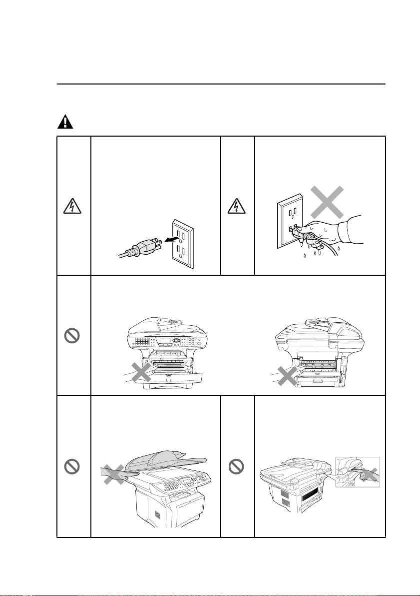
WARNING
There are high voltage
electrodes inside the machine.
Before you clean the m achine
or clear a paper jam, make
sure you have unplugged the
power cord from the power
outlet.
After you use the machine, some internal parts are extremely HOT!
To prevent injuries, be careful not to put your fingers in the area shown in
the illustration.
To prevent injuries, be careful
not to put your hands on the
edge of the machine under the
document cover.
Do not handle the plug with wet
hands. Doing this might cause
an electrical shock.
To prevent injuries, be careful
not to put your fingers in the
area shown in the illustration.
i
Page 4

To prevent injuries, be careful not to put
your fingers in the area shown in the
illustration.
WARNING
■ When you move t he machine, grasp th e side ha ndho lds th at a re un der
the scanner. Do NOT carry the machine by holding it at the bottom.
■ Use caution when installing or modifying telephone lines. Never touch
tele pho ne wir es o r termin als that ar e not i nsulated unless the teleph on e
line has been disconnected at the wall jack. Never install telephone
wiring during a lightning storm. Never install a telephone jack in a wet
location unless the jack is specifically designed for a wet location.
■ Inst al l eq ui pmen t wi th a power co rd n ea r a so cket/o utle t th at is ea sily
accessible.
■ To reduce the risk of shock or fire, use only a No. 26 AWG or larger
telecommunication line cord.
■ Do not use a telephone in the vicinity of gas leak to report leak.
■ Do not use this product near appliances that use water, in a wet
basement or near a swimming pool.
■ Avoid using a telephone other than a cordless type during an electrical
storm. There may be a remote risk of electric shock from lightning.
Cauti on
■ Lightning and power surges can damage this product! We recommend
that you use a quality surge protection device on the AC power line and
on the telephone line, or unplug the lines during a lightning storm.
ii
Page 5

Choosing a location
Place your machine on a flat, stable surface that is free of vibration
and shocks, such as a desk. Put the machine near a telephone jack
and a standard, grounded power outlet. Choose a l ocation wh ere the
temperature remains between 50°F and 95.5 °F (10°-32.5°C).
Cauti on
■ Avoid placing your machine in a high-traffic area.
■ Do not place near heaters, air conditioners, water, chemicals, or
refrigerators.
■ Do not expose the machine to direct sunlight, excessive heat,
moisture, or dust.
■ Do not connect your machine to electrical outlets controlled by
wall switches or automatic timers.
■ Disruption of power can wipe out information in the machine’s
memory.
■ Do not connect your machine to electrical outlets on the same
circuit as large appliances or other Equipment th at might disrupt
the power supply.
■ Avoid interference sources, such as speakers or the ba se units
of cordless phones.
NO !
NO ! NO !
ii i
Page 6

Quick Reference Guide
Sending faxes
Automatic Transmission
1 If it is not illuminated in
green, press (Fax).
2 Place the original face up in
the ADF, or face down o n
the scanner glass.
3 Enter the fax number using
One-Touch, Speed Dial,
Search or the di al pad.
4 Press Start.
5 If you are using the scanner
glass, press
Transmission from ADF
You can send faxes in real time.
2 or Start.
1 If it is not illuminated in
green, press (Fax).
2 Place the original face up in
the ADF, or face down o n
the scanner glass.
3 Press Menu, 2, 2, 5.
4 Press or to select
On, and then press
—OR—
For the next transmission
only, press or to
select Next Fax Only,
and then press
Enter.
Enter.
5 For the next fax only, press
or to select Next
Fax:On , and then press
Enter.
6 Press 1 if you want to
choose more Entertings and
the LCD will return to the
Enterup send menu.
—OR—
Press
2 to fax.
7 Enter the fax number.
8 Press Start.
Receiving faxes
Select Answer Mode
1 Press Menu, 0,1.
2 Press or to select
Fax Only, Manual,
Fax/Tel and External
TAM and th en press
Storing numbers
Storing One-Touch Dial
numbe rs
Enter.
1 Press Menu, 2, 3, 1.
2 Press the One-Touch key
where you want to store the
number.
3 Enter a number (up to 20
digits), and then press
Enter.
4 Enter a name (or leave it
blank), and then press
Enter.
5 Press Stop.
v
Page 7

St or ing S pee d Dial nu mbe rs
1 Press Menu, 2, 3, 2.
2 Enter a three-digit Speed
Dial number, and then press
Enter.
3 Enter a numbe r (up to 20
digits), and then press
Enter.
4 Enter a name (or lea ve it
blank), and then press
Enter.
5 Press Stop.
Dial ing operation s
One-Touch Dialing / Speed
Dialing
1 If it is not illuminated in
green, press (Fax).
2 Place the original face up in
the ADF, or face down on
the scanner glass.
3 Press the One-Touch key of
the number you want to call
—OR—
Press
Search/Speed Dial
press #, and then press the
three-digit Speed Dial number.
4 Press Start.
Using Search
1 If it is not illuminated in
green, press (Fax).
2 Press
Search/Speed Di al
and then enter the first letter
of the name you’re looking for.
3 Press or to
search the memory.
4 Press Start.
Making copies
Single copy
1 Press (Copy) to
illuminate it in green.
2 Place the original face up in
the ADF, or face down on
the scanner glass.
3 Press Start.
Sorting multiple copies
(Using the ADF)
1 Press (Copy) to
,
illuminate it in green.
2 Place the original face up in
the ADF.
3 Use th e dial pad to enter the
number of copies you want
(up to 99).
4 Press Sort.
Sort icon appears on the
LCD.
5 Press Start.
,
vi
Page 8

Table of contens
1
Introduction ..........................................................................1-1
Using this Guide ...............................................................1-1
Finding information.................................................1-1
Symbols used in this Guide....................................1-1
Machine part names and operations ..........................1-2
Control panel overview .....................................................1-5
Status LED indications ............................................. 1-10
About fax machines ........................................................1-12
Custom features ....................................................... 1-12
Do you have Voice Mail on the phone line?......... 1-12
Why should there be problems?........................... 1-12
How can you avoid possible problems? ...............1-12
Fax tones and handshake ........................................ 1-13
ECM (Error Correction Mode)................................... 1-14
Connecting the machine ................................................. 1-14
Connecting an external telephone............................ 1-14
Connecting an external telephone answering machine
(TAM) ................................................................... 1-15
Sequence.............................................................1-15
Connections .........................................................1-17
Recording outgoing message (OGM) on an external
TAM..................................................................1-17
Special line considerations .......................................1-18
Two-line phone system ........................................ 1-18
Converting telephone wall outlets ........................1-18
Inst allin g machi ne , ext e rna l tw o-l ine TA M and tw o-l ine
telephone.......................................................... 1-19
Multi-line connections (PBX) .................................... 1-20
If you are installing the machi ne to work with a
PBX ..................................................................1-20
Custom features on your phone line.........................1-20
2
Paper .....................................................................................2-1
About paper ...................................................................... 2-1
Type and size of paper............................................... 2-1
Recommended paper .................................................2-1
Choosing acceptable paper..............................................2-2
Paper capacity of the paper trays...........................2-3
Paper specifications for each paper tray................2-4
How to load paper ......................................................2-5
To load paper or other media in the paper tray......2-5
vii
Page 9

To load paper or other media in the multi-purpose tray
(MP tray)............................................................. 2-7
To use Automatic Duplexing for fax, copy and print
operations...............................................................2-9
3
4
On-screen programming ..................................................... 3-1
User-friendly programming ...............................................3-1
Menu table.................................................................. 3-1
Memory Storage ......................................................... 3-1
Navigation keys ................................................................3-2
Getting started .....................................................................4-1
Initial Setup....................................................................... 4-1
Setting the Date and Time..........................................4-1
Setting the Machine ID ...............................................4-2
Entering text ...........................................................4-3
Inserting spaces ..................................................... 4-3
Making corrections ................................................. 4-3
Repeating letters .................................................... 4-3
Special characters and symbols ............................4-4
Setting Tone and Pulse dialing mode......................... 4-4
System Setup................................................................... 4-5
Setting the Mode Timer .............................................. 4-5
Setting the Paper Type...............................................4-5
Setting the Paper Size................................................ 4-6
Setting the Ring Volume .............................................4-7
Setting the Beeper Volume.........................................4-7
Setting the Speaker Volume....................................... 4-8
Save Toner.................................................................4-8
Sleep Timer ................................................................4-9
Turning off the Scanner Lamp ....................................4-9
Setting the Tray Use for Copy mode ........................4-10
Setting the Tray Use for Fax mode...........................4-11
Setting the Tray Use for Printing Reports.................4-11
Setting the LCD Contrast..........................................4-12
viii
5
RX Settin gs ........................................................................... 5-1
Basic receiving operati ons................................................ 5-1
Choosing the Answer Mode........................................ 5-1
To select or change your Answer Mode................. 5-2
Setting the Ring Count ............................................... 5-2
Setting the F/T Ring Time (Fax/Tel mode only)..........5-3
EXT. TEL. RX ............................................................. 5-4
Page 10

Printi ng a re duced incomi ng fax
(Auto Reduction) .................................................... 5-5
Printing a fax from the memory .................................. 5-5
Setting the Print Density .............................................5-6
Advanced receiving operations ........................................5-7
Operati on from extension telephones.........................5-7
For FAX/TEL mode only .............................................5-7
Using a cordless external handset .............................5-8
Changing the remote codes ....................................... 5-8
Polling .........................................................................5-9
Setting up Polling Receive .....................................5-9
Setting up Sequential Polling Receive .................5-10
Setting Duplex printing for Fax mode ....................... 5-10
Telephone services ........................................................5-11
Unique Ring..............................................................5-11
What does your telephone company’s
‘Unique Ri ng’ do?............................................. 5-11
What does ix2700’s ‘Unique Ring’ do?.................5-11
Do you have Voice Mail?......................................5-12
Before you choose the ring pattern to register ..... 5-12
Registering the Unique Ring pattern ........................5-13
Turning off the Unique Ring .................................5-13
Caller ID ..........................................................................5-14
Viewing Caller ID List ............................................... 5-15
Clearing a Caller ID stored in the memory ...............5-15
Printing Caller ID List................................................ 5-15
6
TX Settings ........................................................................... 6-1
How to Fax .......................................................................6-1
Enter Fax mode ..........................................................6-1
Faxing from the automatic document feeder (ADF) ... 6-1
Faxing from the ADF ..............................................6-2
Faxing from the scanner glass ...................................6-3
Faxing legal size originals from the scanner glass .....6-4
Out of Memory message ........................................6-4
Manual transmission...................................................6-4
Automatic transmission ..............................................6-5
This is the easiest way to send a fax......................6-5
Sending a fax at the end of a conversation ................6-5
Basic sending operations .................................................6-6
Sending faxes using multiple settings ........................6-6
Contrast......................................................................6-6
Fax Resolution............................................................ 6-7
Manual and automatic fax Redial ...............................6-8
ix
Page 11

Dual Access ............................................................... 6-9
Real Time Transmission ...........................................6-10
Checking job status .................................................. 6-11
Canceling a job while scanning the original.............. 6-11
Canceling a scheduled job........................................6-11
Advanced sending operations ........................................6-12
Composing the electronic Cover Sheet .................... 6-12
Composing your own comments ..........................6-13
Cover sheet for the next fax only..........................6-14
Send a cover sheet for all faxes ...........................6-15
Using a printed cover sheet......................................6-15
Broadcasting.............................................................6-16
Overseas Mode........................................................ 6-18
Delayed Send...........................................................6-19
Delayed Batch Transmission....................................6-20
Setting up Polled Transmission ................................6-21
Memory Security.......................................................6-22
Setting up the password.......................................6-22
Turning Memory Security on ................................6-23
Turning Memory Security off.....................................6-23
7
8
x
Auto Dial numbers and dialing options ............................. 7-1
Storing numbers for easy dialing...................................... 7-1
Storing One-Touch Dial numbers............................... 7-1
Storing Speed Dial numbers....................................... 7-2
Changing One-Touch and Speed Dial numbers.........7-3
Setting up Groups for Broadcasting............................7-4
Dialing options.................................................................. 7-5
Search........................................................................ 7-5
One-Touch Dialing......................................................7-5
Speed Dialing ............................................................. 7-6
Manual dialing............................................................. 7-6
Using an external telephone....................................... 7-6
Access codes and credit card numbers...................... 7-7
Pause ......................................................................... 7-8
Tone or Pulse............................................................. 7-8
Remote Fax Options ............................................................ 8-1
Fax Forwarding.................................................................8-1
Programming a Fax Forwarding number.................... 8-1
Setting Remote Retrieval.................................................. 8-2
Local Print............................................................... 8-2
Using R R Passcode...................................................8-3
Remote commands..................................................... 8-4
Page 12

Retrieving fax messages ............................................8-5
Changing your Fax Forwarding number .....................8-5
9
10
Printing reports ....................................................................9-1
Machine settings and journal ............................................9-1
Customizing the Job Status Report ............................9-1
Setting the Journal Interval .........................................9-2
Printing reports ...........................................................9-3
To print a report......................................................9-3
Making copies .................................................................... 10-1
Using the machine as a copier ....................................... 10-1
Enter Copy mode...................................................... 10-1
Temporary copy settings...................................... 10-2
Making a single copy from the ADF..........................10-3
Making multiple copies from the ADF....................... 10-3
Si ng le or mu lt ip le copi es usi ng the scann er glass .... 1 0- 4
Out of Memory message ..........................................10-5
Using the copy keys
(Temporary settings) ...................................................10-6
Enlarge/Reduce........................................................10-7
Copy Mode (type of original) .................................... 10-8
Sorting copies using the ADF ................................... 10-9
Contrast.................................................................... 10-9
Tray Select ............................................................. 10-10
Duplex/N in 1 ..........................................................10-11
Duplex/N in 1 copy ................................................. 10-12
N in 1 copy ......................................................... 10-12
Poster................................................................. 10-13
Duplex (1 in 1).................................................... 10-13
Duplex (2 in 1) and Duplex (4 in 1)..................... 10-15
Changing the default copy settings .............................. 10-16
Copy Mode ............................................................. 10-16
Contrast.................................................................. 10-16
11
Using the Machine as a printer ......................................... 11-1
Using the ix2700 printer driver........................................ 11-1
How to print your document............................................ 11-2
Simultaneous printing and faxing ................................... 11-3
Two-sided printing (Duplex Printing) ........................11-3
Automatic Duplex Printing.................................... 11-3
Manual Duplex Printing........................................ 11-4
Face-down output tray.............................................. 11-4
Printing on plain paper.............................................. 11-5
xi
Page 13

The MP tray..........................................................11-5
Printing on thicker paper and card stock ..................11-6
The multi-purpose tray (MP tray)..........................11-6
Printing on envelopes............................................... 11-8
Printer operation keys...................................................11-11
Job Cancel.............................................................. 11-11
Secure key.............................................................. 11-11
Setting the Emulation Selection.............................. 11-12
Printing the Internal Font List..................................11-13
Printing the Print Configuration List........................11-13
Restoring factory defaul t settings........................... 11-13
12
Printer driver settings ........................................................ 12-1
Printer driver settings......................................................12-1
How to access the printer driver settings........................12-1
Features in the Native Driver..........................................12-2
Basic tab...................................................................12-2
Paper Size............................................................ 12-3
Multiple Page........................................................12-3
Orientation............................................................12-3
Copies ..................................................................12-4
Media Type...........................................................12-4
Advanced tab............................................................ 12-5
Print Quality..........................................................12-5
Duplex Printing .....................................................12-7
Watermark............................................................12-8
Page Setting.......................................................12-10
Device Options ................................................... 12-11
Secure Print............................................................12-11
Accessories tab ..................................................12-15
Fe ature s i n t he PS pr int e r dr iver
(For Windows®).......................................................... 12-16
Ports tab................................................................. 12-16
Device Settings tab................................................. 12-17
Layout tab............................................................... 12-18
Booklet (For Windows® 2000/XP).......................12-18
Paper / Quality tab .................................................. 12-19
Advanced Options ..................................................12-20
xii
13
How to scan using W indows® ...........................................13-1
Scanning a document ....................................................13-1
TWAIN compliant......................................................13-1
How to access the Scanner......................................13-2
Scanning a document into the PC............................13-3
Page 14

Scanning a whole page........................................ 13-3
Pre Sca nning to cr op a po rtio n you want to sca n .. 1 3- 4
Settings in the Scanner window ............................... 13-6
Image Type .......................................................... 13-6
Resolution ............................................................13-6
Scan Type ............................................................ 13-7
Brightness ............................................................ 13-7
Contrast................................................................ 13-7
Document Size.....................................................13-8
Scanning a document
(For Windows® XP only)............................................ 13-10
WIA compliant ........................................................ 13-10
How to access the scanner ....................................13-10
Scanning a document into the PC .......................... 13-11
Scanning a document using the ADF................. 13-11
PreScanning to crop a portion you want to scan using
the scanner glass........................................... 13-13
Scanner Utility.................................................... 13-15
Using the scan key (For USB or Parallel interface cable
users).........................................................................13-16
Scan to E-mail ........................................................ 13-17
Scan to Image ........................................................ 13-17
Scan to OCR ..........................................................13-18
Scan to File............................................................. 13-18
Using ScanSoft® Pape rP o rt® and TextBri dg e® OCR....13-19
Viewing items ......................................................... 13-20
Organizing your items in folders ............................. 13-21
Quick links to other applications ............................. 13-21
ScanSoft® TextBridge® OCR lets you convert image text
into text you can edit .......................................... 13-22
You can Import items from other applications ........ 13-22
You can Export items in other formats ...................13-23
Exporting an image file....................................... 13-23
How to Uninstall PaperPo rt® and S can Soft®
TextBridge®........................................................ 13-24
14
Using the SmartUI for Windows® 95/9 8/98S E/ Me/20 00
Professional and Windows NT® WS 4.0 ........................... 14-1
SmartUI .................................................................... 14-1
AutoLoad the SmartUI.............................................. 14-2
How to turn off AutoLoad ..........................................14-2
SmartUI features ............................................................14-3
Auto Configuration.................................................... 14-3
Scan key operations ................................................. 14-4
xiii
Page 15

Copy operations........................................................14-4
PC-Fax operation......................................................14-4
Scanner settings for Scan, Copy and
PC-Fax buttons.....................................................14-5
Global settings..........................................................14-5
Setting up the scanner configurations ......................14-6
Perform an operation from the SmartUI screen........14-7
Scan to File..................................................................... 14-8
To access Scan to File Configurations screen .........14-8
Scanner settings....................................................... 14-8
Destination folder......................................................14-9
Scan to E-mail .............................................................. 14-10
To access Scan to E-mail Configurations screen... 14-10
Scanner settings..................................................... 14-10
E-mail application ................................................... 14-11
Send to Options...................................................... 14-11
Scan to OCR (Word Processor) ................................... 14-12
To access Scan to OCR Configurations screen .....14-12
Scanner settings..................................................... 14-12
Word Processor...................................................... 14-13
Scan to Image............................................................... 14-14
To access Scan to Image Configurations screen... 14-14
Scanner Settings .................................................... 14-14
Target Application...................................................14-14
Copy ............................................................................. 14-15
To access the Copy Configurations screen............ 14-15
Scanner settings..................................................... 14-15
Number of copies....................................................14-15
Send a fax.....................................................................14-16
To access the Send a fax Configurations screen... 14-16
Scanner settings..................................................... 14-16
PC-FAX Settings..................................................... 14-17
xiv
15
Using the Windows®-Based SmartUI ...............................15-1
SmartUI...........................................................................15-1
AutoLoad the SmartUI.............................................. 15-2
How to turn off Auto Load.........................................15-2
SmartUI features.............................................................15-3
Auto Configuration ....................................................15-4
Hardware Section: Changing the Scan to button
configuration ................................................................ 15-5
Scan to E-mail ..........................................................15-6
Scan to File...............................................................15-7
Scan to Image ..........................................................15-8
Page 16

Scan to OCR ..........................................................15-10
Software Section ..........................................................15-12
Scan ....................................................................... 15-13
Copy ....................................................................... 15-13
Fax .......................................................................... 15-14
Custom ...................................................................15-14
Scan to File................................................................... 15-15
Scan to E-mail .............................................................. 15-17
File attachments ..................................................... 15-19
Scanner settings..................................................... 15-20
Scan to OCR (Word Processing program) ...................15-21
Scan to Graphics application
(example: Microsoft Paint).........................................15-23
Copy ....................................................................... 15-25
Fax setting (PC-Fax using the ix2700 Fax Driver)........ 15-27
FAX settings ........................................................... 15-28
Custom: User-defined buttons...................................... 15-30
Customizing a user-defined button ......................... 15-30
1. Select the Scan Action................................... 15-30
2. Select Configuration for the Scan Type..........15-31
3. Select Scan Settings. .....................................15-35
16
17
Using Remote Setup .......................................................... 16-1
Remote Setup .................................................................16-1
Using PC-FAX software .....................................................17-1
PC-FAX sending.............................................................17-1
Setting up user information.......................................17-2
Sending setup........................................................... 17-3
Outside line access .................................................. 17-4
Include header.......................................................... 17-4
Addressbook file....................................................... 17-4
User interface ........................................................... 17-5
Simple style.......................................................... 17-5
Facsimile style...................................................... 17-5
Speed Dial setup ............................................................ 17-6
The Address Book ....................................................17-7
Setting up a Member in the Address Book ...............17-8
Setting up a Group for Broadcasting ........................17-9
Editing Member information ....................................17-10
Deleting a Member or Group.................................. 17-10
Exporting the Address Book ................................... 17-10
Importing to the Address Book ...............................17-12
Setting up a Cover Page ........................................ 17-13
xv
Page 17

You can enter information in each field.................. 17-14
Sen di ng a file as a PC-FAX usin g th e
Facsimile style ....................................................17-15
Redial ................................................................. 17-16
Sen di ng a file as a PC-FAX usin g th e S imp le st yle 17-1 6
Setting up PC-FAX receiving
(Windows® 95/98/98SE/Me/2000 Professional and
Windows NT® WS 4.0 only)....................................... 17-18
Running PC-FAX Receiving ................................... 17-18
Setting up your PC.................................................. 17-18
Viewing new PC-FAX messages............................ 17-19
Receiving a fax into the PC
(Windows® XP only)................................................... 17-20
How to receive a fax automatically......................... 17-20
How to view the received faxes.............................. 17-25
18
Using your Machine with a Macintosh® ...........................18-1
Setting up your USB-equipped Apple® Macintosh® .......18-1
Using the printer driver with your Apple® Macintosh®
(Mac OS 8.6-9.2) .........................................................18-2
Usi ng th e Printer D river with Your Apple® Macintosh®
(Mac OS X) ..................................................................18-5
Choosing page setup options...................................18-5
Specific settings........................................................18-6
Using the PS driver with your Apple® Macintosh®.......... 18-8
For Mac OS 8.6 to 9.2 users.....................................18-8
For Mac OS X users............................................... 18-12
Sending a fax from your Macintosh® application ..........18-15
For Mac OS 8.6-9.2 users ......................................18-15
For Mac OS X users............................................... 18-17
Drag a vCard from the Mac® OS X Address Book
application ...................................................... 18-19
Using the TWAIN scanner driver with your Macintosh®18-21
Accessing the scanner............................................ 18-21
Scanni ng an i ma ge into yo ur Maci nto sh®...............18-22
Scanning a whole page...................................... 18-22
PreScanning an image...........................................18-23
Settings in the Scanner window.............................. 18-24
Image.................................................................. 18-24
Scanning Area....................................................18-26
Business Card Size............................................ 18-26
Adjusting the Image............................................ 18-27
Remote Setup (Mac OS® X) .........................................18-28
xvi
Page 18

19
Network Scanning
(W ind ows® 98/98SE/Me/2000 Professional
and XP o nly) .......................................................................19-1
Registering your PC with the machine .....................19-1
Using the Scan key .........................................................19-4
Scan to E-mail (PC).................................................. 19-4
Scan to E-mail (E-mail server)..................................19-5
Scan to Image .......................................................... 19-6
Scan to OCR ............................................................19-7
Scan to File............................................................... 19-8
20
21
Network PC-FAX software ................................................20-1
Enable Network PC-FAX .......................................... 20-1
Sending setup ...................................................... 20-1
Extra options in Address Book ............................. 20-3
Installing Network PC-FAX ....................................... 20-4
Window s® 95/98/98SE and Me users .................. 20-4
Using the Network PC-FAX software ....................... 20-5
Quick Tips: ........................................................... 20-5
Sen ding a Network P C-FAX f r om yo ur Maci ntosh®
application ............................................................20-6
For Mac OS 8.6-9.2 users.................................... 20-6
For Mac OS X users............................................. 20-6
Imp ortant in formation ....................................................... 21-1
Standard telephone and FCC Notices
These notices are in effect on models sold and used
only in the United States. ..................................... 21-1
Federal C ommunications Commission (FCC) Declaration
of Conformity (USA only)......................................21-3
Important.............................................................. 21-4
Important – about the interface cable................... 21-4
Industry Canada Compliance Statement
(Canada only)....................................................... 21-4
International ENERGY STAR®
Compliance Statement......................................... 21-4
Laser safety ..............................................................21-4
FDA regulations ........................................................21-5
Important safety instructions...........................................21-6
Trademarks .................................................................... 21-8
xvii
Page 19

22
Troubleshooting and routine maintenance .....................22-1
Troubleshooting .............................................................22-1
Error messages........................................................22-1
Original jams.............................................................22-4
Original is jammed in the top of the ADF unit....... 22-4
Original is jammed inside the ADF uni t. ...............22-5
Paper jams................................................................ 22-6
Paper is jammed in the duplex tray ....................22-11
If you are having difficulty with your machine......... 22-13
Improving the print quality....................................... 22-17
Packing and shipping the machine............................... 22-21
Routine maintenance....................................................22-24
Cleaning the scanner..............................................22-24
Cleaning the printer ................................................ 22-25
Cleaning the drum unit............................................ 22-26
Replacing the toner cartridge..................................22-27
How to replace the toner cartridge.......................... 22-28
Replacing the drum unit.......................................... 22-33
Page Counter ......................................................... 22-36
23
G
Optional accessories .........................................................23-1
Memory board.................................................................23-1
Installing the optional memory board........................23-2
Network (LAN) board ......................................................23-4
Before starting installation ........................................23-5
Step 1: Hardware installation....................................23-5
Step 2: Connecting the Network board to an Unshielded
Twisted Pair 10BASE-T or 100BASE-TX Ethernet
Network ................................................................ 23-8
LED.......................................................................23-8
TEST SWITCH.....................................................23-9
Lower Tray................................................................23-9
Glossary ............................................................................... G-1
xviii
Page 20

S
Specifications ......................................................................S-1
Product description ...........................................................S-1
General .............................................................................S-1
Print media .......................................................................S-2
Copy .................................................................................S-2
Fax ....................................................................................S-3
Scanner ............................................................................S-4
Printer ...............................................................................S-5
Interfaces..........................................................................S-5
Computer requirements....................................................S-6
24
25
Index ......................................................................................I-1
Remote Retrieval Access card .......................................... R-1
xix
Page 21

1
Introduction
Using this Guide
Thank you for buying an Imagistics ix2700. Your ix2700 is simple to
use, with LCD screen instructions to guide you through programming
it. You can make the most of your machine by taking a few minutes to
read this Guide.
Finding information
All the chapter headings and subheadings are listed in the Table of
Contents. You will be able to find information about a specific feature
or operation by checking the Index at the back of this Guide.
Symbols used in this Gui de
Throughout this Guide you’ll see special symbols alerting you to
important warnings, notes and actions. To make things clearer and
to help you press the correct keys, we used special fonts and added
some of the messages that will appear in the LCD.
Bold Bold typeface identifies specific keys on the
machine control panel.
Italics Italicized typeface emphasizes an important po int
or refers you to a related topic.
Courier
New
Courier New typeface identifies the messages on
the LCD of the machine.
Warnings inform you what to do to avoid possible personal
injury.
Cautions specify procedures you must follow or avoid to
prevent possible damage to the machine.
Notes tell you how you should respond to a situation that may arise or
give tips about how the current operation works with other features.
Improper Setup alerts you to devices and operations that are not
compatible with the machine.
INTRODUCTION 1 - 1
Page 22

Machine part names and operations
■ Front view
5 Automatic Document Feeder (ADF)
4 Co nt ro l Pan el
3 Face- dow n Ou tput T ray
Sup por t Fla p with Exten sio n
2 F ro nt Cover Rele as e But ton
1 Multi -purpose Tray ( MP Tray)
11 Paper Tray (Upper Tray)
No. Name Description
1 Multi-purpose Tray (MP Tray) Load paper here.
2 Front Cover Release Button Press it to open the front cover.
3 Face-down Output Tray Support Flap
with Extension (Support Flap)
Unfold it to prevent the printed paper
from sliding off the machine.
4 Control Panel Use the keys and dis play to control
the machine.
5 Automatic D ocument Feeder (ADF) Use the ADF unit f or multiple page
originals.
6 ADF D ocument Support Extension Place the original here t o use the
ADF unit.
7 ADF D ocument Output Support Flap Unfold to prevent the scanned pages
from sliding off the machine.
8 Document Cover Open to place the original on the
scanner glass.
9 Power Switch Switch it on or of f.
10 Front Cover Open to install a toner cartridge or
drum unit.
11 Paper Tray (Upper Tray) Load paper here.
6 ADF D ocu ment Sup po rt
Exte nsi on
7 ADF Document
Output Support
Flap
8 Document Cover
9 Power Switch
10 Front Co ver
1 - 2 I NTRODUCTION
Page 23

■ Back vi ew
16 ADF Cover
15 Face -up Ou tpu t Tra y
(Back Output Tray)
14 A C Powe r Conn ecto r
13 Duplex Tray
12 Pa per Adj u stme nt Lev er
for D uple x Printin g
20 Ext er na l Te l ep hone
Line Jack
No. Name Description
12 Paper Adjustment Lever for
Duplex Printing
Use to match your paper size for duplex
printing.
13 D uplex Tray Slide out to remove paper jam med inside
the machine.
14 AC Power C onnector Connect the AC Power Connector here.
15 F ace-up Output T ray
(Back Output Tray)
Open it when thicker paper is placed in the
MP tray .
16 AD F Cover Open to remove paper jammed inside the
ADF unit.
17 T elephone Line Jac k Plug the line cord supplied w ith the machine
into here.
18 U SB Interface Connec tor Connect the USB Cable here.
19 Parallel Interface Connector Connect the Parallel Cable here.
20 Ex ternal Telephone Line Jack Plug in the modular plug on the external
telephone line here.
17 Tel ep hon e Line Jack
18 US B Interface
Conn ecto r
19 Parallel I nterf ace
Conn ecto r
INTRODUCTION 1 - 3
Page 24

■ Inside view (Document cover open)
24 Document Cover
23 Scanner Lock Lever
22 Glass Strip
21 Document
Guidelines
25 White Film
26 Scann er Gl a ss
No. Name Description
21 Document Guidelines Use to center the original on the scanner glass.
22 Glass Strip This is used to scan the original when using the
ADF.
23 Scanner Lock Lever Use to lock/unlock the scanner w hen relocating the
machine.
24 Document Cover Open to place the original on the scanner glass.
25 White F ilm Clean it for good quality copying and scanning.
26 Scanner Glass Place the original to be scanned here.
1 - 4 I NTRODUCTION
Page 25

Control panel overview
10 11
9
12
5 8
4
2
1 3
6
7
INTRODUCTION 1 - 5
Page 26

1 3
2
4
5
Shift
1
To access memory locations 21
through 40 in the One-Touch keys
hold down the Shift key.
One-Touch keys
2
These 20 keys give you instant
access to 40 previously stored dial
numbers.
Print keys:
3
Secure
Lets you print out data s aved in
memory by entering your four-digit
password.
Job cancel
Clears data from the printer
mem or y.
7
4
5
Status LED
(Light-Emitting Diode)
The LED will flash and change color
depending on the machine status.
5-Line Liquid Crystal Display
(LCD)
Displays messages on the screen to
help you to set up and use your
machine.
6
1 - 6 I NTRODUCTION
Page 27

Mode keys:
6
Fax
Lets you access Fax mode.
Copy
Lets you access Copy mode.
Scan
Lets you access Scan mode.
Fax and telephone keys:
7
Mo nit or
Press before dialing if you want to
make sure a fax machine will
answer, and then press Start.
Resolution
Sets the res olution w hen you s end a
fax .
Search/Speed Dial
Lets you look up numbers that are
stored in the dialing memory . I t also
lets you dial s tored numbers by
pressing # and a three-digit number.
Redial/Pause
Redials the last number you called.
It also inserts a pause in auto dial
numbers.
INTRODUCTION 1 - 7
Page 28

8
9
10 11
12
Navigation keys:
8
Men u
Lets you access the Menu to
program.
Enter
Lets you store your settings in the
machine.
Clear/Back
Deletes entered data or lets you exit
the menu by pressing repeatedly.
1 - 8 I NTRODUCTION
or
Press to scroll forward or backward
to a menu selection.
When using the speaker or ring, you
can press these keys t o adjust the
volume in fax mode.
or
Press to scroll through t he menus
and options.
Also, you can use these keys to do
a numerial search for t he names of
stored numbers in fax mode.
Page 29

Copy keys
9
(Temporary settings):
Enlarge/Reduce
Lets you reduce or enlarge c opies
depending upon the ratio you
selec t.
Contrast
Lets you make a copy that is lighter
or darker than the original.
Mo de
Lets you select the copy mode for
your type of original.
Tray Select
You can s elect which tray you w ould
like to use for the next copy.
Sort
Lets you sort multiple copies using
the ADF.
Duplex/N in 1
You can choose Duplex to c opy on
both sides of the paper or N in 1 to
copy 2 or 4 pages onto one page.
Dial Pa d
0
Use these keys to dial telephone
and fax numbers and as a keyboard
for entering information into the
machine.
The # key lets you temporarily
switch the dialing mode during a
telephone call from Pulse to T one.
A
Stop
Stops a fax, copy and scan
operation or exits from the menu.
B
Start
Lets you start sending faxes,
making copies or scanning.
INTRODUCTION 1 - 9
Page 30

Status LED indications
Th e Status LED (Light Emitting Diode) will flash and change color
depending on the machine status.
The LED indications shown in the table below are used in the
illustrations in this chapter.
LED LED status
LED is off.
LED is on.
Green Yellow Red
LED is blinking.
Green Yellow Red
LED machine status Description
Sleep Mode The power switch is off or the machine is in
Sleep mode.
Warming Up The machine is warming up for printing.
Green
Ready The machine is ready to print.
Green
Receiving Data The machine is either receiving data from the
Yellow
Data Remaining in
Mem or y
Yellow
1 - 10 I NTRODUCTION
computer, processing data in memory or
printing data.
Print data remains in t he machine memory.
Page 31

LED machine status Description
Service error Follow the steps below.
1. Turn off the power sw itch.
2. Wait a few seconds, and then turn it back on
and try to print again.
Red
Cover open The cover is open. C lose the cov er. (See
Toner empty Replace the toner cartridge with a new one.
Paper error Put paper in the tray or clear the paper jam.
Red
Scan lock Check that the scanner lock lev er is released.
Others Check the LCD message. ( See Troubleshooting
Out of memory Memory is full. ( See
If you cannot clear the error and see the same
service call indication after turning the machine
back on, please call the I magistics National
Diagnostic Center at 1-800-243-5556 (In U SA).
messages on page 22-1 . )
(See Replacing the toner cartridge on page
22-27.)
Check the LCD message. ( See Troubleshooting
on page 22-1.)
(See Scanner Lock Lever on page 1-4.)
on page 22-1.)
22-1.)
Error
Error messages on page
When the power switch is off or the machine is in Sleep mode,
the LED is off.
INTRODUCTION 1 - 11
Page 32

About fax machines
Custom features
Do you have Voice Mail on th e phone li ne?
If you have Voice Mail on the phone line where you will install your
new machine, there is a strong p ossibility that Voice Mail and the
machine may conflict with each other while receiving incoming calls.
Why should there be problems?
Since both the machine and Voice Mail will pick up the call, after the
number of rings you have set, each of them has the ability to keep
the other from receiving calls.
For example, if your Voice Mail is set to answer after two rings and
your machine is set to answer after four, your Voice Mail will stop
your machine from receiving faxes.
If you set Voice Mail and the machine to answer after the same
number of rings, there is no way of knowing which one will answer
first. It is important to remember that neither Voice Mail nor the
machine can pass the call back to the other after the call has been
answered.
How can you avoid possible problems?
A very good way to avoid problems like the one mentioned,
a second phone numbe r on your present phone line.
Many pe ople with Voice M ail choose an alternative service, which is
called “Unique Ring”, and they are very satisfied with it. (See
Ring on page 5-11.)
Another way to avoid possible problems is to replace your Voice Mail
with an answering machine. Your machine is designed to work with
an answering machine or TAM (telephon e answe ring machine).
Connecting an external telephone answering machine (TAM)
(See
on page 1-15.)
1 - 12 I NTRODUCTION
is to get
Unique
Page 33

Fax tones and handshake
When someone is sending a fax, the machine sends fax calling tones
(CNG tones). These are quiet, intermittent beeps every 4-seconds.
You’ll hear them after you dial and press
for about 60 seconds after dialing. During that time, the sending
machine must begin the “handshake”, or connection, with the
receiving machine.
Each time you use automa tic procedures to send a fax, you are
sending CNG tones over the phone line. You’ll soon learn to listen for
these quiet beeps each time you answer a pho ne on your fax line, so
you will know if you are receiving a fax message.
The receiving fax responds with fax receiving tones, which are loud,
chirping sounds. A receiving fax chirps for about 40 seconds over the
phone line, and the LCD shows Receiving.
If your machine is set to the Fax Only mode, it will answer every call
automatically with fax receiving tones. If the other person hangs up,
your machine will continue to send the “chirps” for about 40 seconds,
and the LCD continues to show Receiving. To cancel receiving,
press
Stop.
The fax ‘handshake’ is the time in which the sending machine’s CNG
tones and the receiving machines “chirps” overlap. This must be for
at least 2 to 4 seconds, so both machines can understand how each
is sending and receiving the fax. The h andshake cannot begin until
the call is answered, and th e CNG tones only last for about 60
seconds after the num ber is dialed. So it is important for the receiving
machine to answer the call in as few rings as possible.
Start and they will continue
When you have an external Telephone Answering machine
(TAM) on your fax line, your TAM will decide the number of rings
before the call is answered.
Pay special at tention to the directions for connecting a TAM in
this chapter. (See
machin e (TAM) on page 1-15.)
Connecting an external telephone answering
INTRODUCTION 1 - 13
Page 34

ECM (Err or Correction Mode)
The Error Correction Mode (ECM) is a way for the machine to check
a fax transmission while it is in progress. If the machine detects
errors during fax transmission, if resends the pages of the fax that
had an error. ECM transmissions are on ly possible between f ax
machines that both have this feature. If they do, you may send and
receive fax messages that are continuously being checked by the
machine.
Your machine must have enough memory for this feature to work.
Connecting the machine
Connecting an external telephone
Although your machine does not have a handset, you can connect a
separate telephone (or telephone answeri ng device) directly to your
machine as shown in the diagram b elow.
Connect the modular plug on the telephone’s line cord to the jack
labeled EXT. in the back of the m achine.
Whenever this phone (or TAM) is in use, the LCD shows
Telephone.
1 - 14 I NTRODUCTION
Page 35

Connecting an external telephone answering machine (TAM)
Sequ ence
You may choose to connect an answering device. However, when
you have an ex ternal TAM on the same telephone line as the
machine, the TAM answers all calls and the machine “listens” for fax
calling (CNG) tones. If it hears them, the machine takes over the call
and receives the fax. If it doesn’t hear CNG tones, the machine lets
the TAM continue playing your outgoing message so your caller can
leave you a voice message.
The TAM must answer within four rings (the recommended setting is
two rings). The machine cannot hear CNG tones until the TAM has
answered the call, and with four rings there are only 8 to 10 seconds
of CNG tones left for the fax “handshake”. Make sure you carefully
follow the instructions in this guide for recording your outgoing
message. We do not recommend using the t oll saver feature on your
external answering machine if it exceeds five rings.
If you do not receive all your faxes, reduce the Ring Delay
setting on your external TAM.
If You Subscri be to your Telephone Com pany’s Unique Ring
Service:
You may connect an external TAM to a separate wall jack only
if you subscribe to your telephone compan y’s Unique Ring
service, have registered the unique ring pattern on your
machine, and use that number as a fax number. The
recommended setting is four rings on the external TAM when
you have the tel ephone company’s Unique Ring Service.
If You Do Not Su bscribe to Unique Ring Service:
You must plug your TAM into the EXT. jack of your machine. If
your TAM is plugged into a wall jack, bo th your machine and the
TAM will try to control the p hone line. (See illustration on the
next page.)
INTRODUCTION 1 - 15
Page 36

Do not connect a TAM elsewhere on the same phone line
(unless you have the Unique Ring service).
TAM
TA M
1 - 16 I NTRODUCTION
Page 37

Connections
The external TAM must be plugged into the back of the m achine, i nto
the jack labeled EXT. Your machine cannot work properly if you plug
the TAM into a wall jack (unless you are using Unique Ring).
1 Plug the t elephone line cord from th e wall jack into the ba ck of
the machine, i n the jack labeled LINE.
2 Plug the t elephone line cord from your external TAM into the
back of the machine, in the jack labeled EXT. (Make sure this
cord is connected to the TAM at the TAM’s telephone line jack,
and not its telephone jack.)
3 Set your external TAM to four rings or less. (The machine’s Ring
Count setting does not apply.)
4 Record the outgoing message on your external TAM.
5 Set the TAM to answer calls.
6 Set the Answer Mode to External TAM.
(See Cho osing the An swer Mode on page 5-1.)
Recording outgoing message (OGM) o n an external TAM
Timing is important in recording this message. The message sets up
the ways to handle both manual and autom atic fax reception.
1 Record 5 seconds of silence at the beginning of your message.
(This allows your machine time to listen for the fax CNG tones
of automatic transmissions before they stop.)
2 Limit your speaking to 20 seconds.
3 End your 20-second message by giving your Fax Receive Code
for people sending manual faxes. For example:
“After the beep, leave a message or send a fax by pressing
51 and Start.”
We recommend beginning your OGM with an initial 5-second
silence because the machine cannot hear fax tones over a
resonant or loud voice. You may try omitting this pause, but if your
machine has trouble receiving, then you must rerecord the OGM
to include it.
INTRODUCTION 1 - 17
Page 38

Special line considerations
Two-lin e phone system
A two-line phone system is nothing more than two separate phone
numbers on the same wall outlet. The two phon e numbers can be on
separate jacks (RJ11) or combined into one jack (RJ14). Your
machine must be plugged into an RJ11 jack. RJ11 and RJ14 jacks
may be equal in size and ap pearance and both may contain four
wires (black, red, green, yellow). To test the type of jack, plug in a
two-line phone and see if it can access both lines. If it can, you must
separate the line for your m achine. ( See
Convertin g teleph one wall outlets
There are three ways to convert to an RJ11 jack. The first two ways
may require assistance from the telephone company. You can
change the wall outlets from one RJ14 jack to two RJ11 jacks. Or,
you can have an RJ11 wall outlet installed and slave or jump one of
the phone numbers to it.
The third way is the easiest: Buy a triplex adapter. You can plug a
triplex adapter into an RJ14 outlet. It separates the wires into two
separate RJ11 jacks (Line 1, Line 2) and a third RJ14 jack (Lines 1
and 2). If your machine is on Line 1, plug the machine into L1 of the
triplex adapter. If your machine is on Li ne 2, plug it into L2 of the triple
adapter.
EXT. TEL. RX on page 5-4.)
1 - 18 I NTRODUCTION
Triplex Adapter
RJ14
RJ11
RJ14
Page 39

Installin g machine, external two -lin e TAM and two-l ine telephone
When you are installing an external two-line telephone answering
machine (TAM) and a two-line telephone, your machine must be
isolated on one line at bo th the wall jack and at the TAM. The most
common connection is to put the machine on Line 2, which is
explained in the following steps. The back of the two-line TAM must
have two telephone jacks: one labeled L1 or L1/L2, and the othe r
labeled L2. You will need at least three tele phone line cords, the one
that came with your machine and two for your external two-line TAM.
You will need a fourth line cord if you add a two-line telephone.
1 Place the two-line TAM and the two-line telephone next to your
machin e.
2 Plug one end of the telephone line cord for your machine into the
L2 jack of the triplex adapter. Plug the other end into the LINE
jack on the back of the machine.
3 Plug one end of the first telephone line cord for your TAM into
the L1 jack of the triplex adapter. Plug the other end into the L1
or L1/L2 jack of the two-line TAM.
4 Plug one end of the second telephone line cord for your TAM
into the L2 jack of the two-line TAM. Plug the other end into the
EXT. jack on the left side of the machine.
Triplex Adapter
Two Line Phone
External Two Line TAM FAX
You can keep two-line telephones on other wall outlets as always.
There are two ways to add a two-line telephone to the ma chine’s wall
outlet. You can plug the telephone line cord from the two-line
telephone into the L1+L2 jack of the triplex adapter. Or, you can plug
the two-line telephone into the TEL jack of the two-line TAM.
INTRODUCTION 1 - 19
Page 40

Multi-line connections (PBX)
Most offices use a central telephone system. While it is often
relatively simple to connect the machine to a key system or a PBX
(Private Branch Exchange), we suggest that you contact the
company that installed your telephone system and ask them to
connect the machine for you. It is advisable to have a separate line
for the machine. You can then leave the Receive Mode set to FAX
Only to receive faxes any time of the day or ni ght.
If the machine is to be connected to a m ulti-line system, ask your
installer to connect the unit to the last line on the system. This
prevents the unit from bei ng activated each time a telephone call is
received.
As with all fax units, this machine must be connected to a two
wire system. If your line has more than two wires, p roper
connection of the machin e cannot be made .
If you are installing the machine to work with a PBX
1 It is not guaranteed that the unit will op erate correctly under all
circumstances with a PBX. Any cases of difficulty should be
reported first to the company that handles your PBX.
2 If all incoming calls will be answered by a switchboard operator,
it is recommended that the Receive Mode be set to Ma nua l . All
incoming calls should initially be regarded as telephone calls.
Custom features on your phone line
If you have Voice Mail, Call Waiting, Caller ID, RingMaster, an
answering service, an alarm system or other custom feature on one
phone line it may create a problem with the ope ration of your
machine. ( See
1 - 20 I NTRODUCTION
Custom features on page 1-12.)
Page 41

2
Paper
About paper
Type and size of paper
The m achine loads paper from the installed pape r tray,
multi-purpose tray or optional lower tray.
Recommended paper
Plain Paper: Imagistics 471-1 Letter
Imagistics 472-2 Legal
Transparency: 3M CG 3300
Labels: Avery laser label # 5160
■ Before you buy a large amou nt of paper, please test some to
make sure that the p aper is suitable.
■ Use paper that is made for plain-paper copying.
2
■ Use paper that is 75 to 90 g/m
■ Use neutral paper. Do not use acidic or alkaline paper.
■ Use long-grain paper.
■ Use paper with a moisture content of approximately 5%.
(20 to 24 lb).
Cauti on
Do not use ink jet paper. It may cause a paper jam and damage your
machine.
PAPER 2 - 1
Page 42

Choosing acceptable paper
We recommend that you test paper (especially special sizes and
types of paper) on th e machine before purchasing large quantities.
■ Avoid feeding label sheets that are partly used or your machine
will be damaged.
■ Avoid using coated paper, such as vinyl coated paper.
■ Avoid using preprinted or highly textured paper, or paper with an
embossed letterhead.
For optimum printing, use a recommended type of paper, especially
for plain paper and transparencies. For more information on paper
specifications, call your nearest authorized sales representative or
the place where you purchased your machine.
■ Use label or transparencies that are designed for use in las er
printers.
■ For the best print quality, we recommend using long-grained
paper.
■ If you are using special paper and the paper has problems
feeding from the pap er tray, try again using the multi-purpose
tray.
■ You can use recycled paper in this machine.
2 - 2 PAPER
Page 43

Paper capacity of the paper trays
Paper size Number of sheets
Multi-purpose tray
(MP tray)
Paper tray
(Upper Tray)
Optional lower tray A4, Letter, Legal, B5 (ISO), B5
Duplex printing A4, Letter, Legal —
Width: 69.8 to 220 mm
(2.75 to 8.66 in.)
Height: 116 to 406.4 mm
(4.57 to 16.0 in.)
A4, Letter, Legal, B5 (ISO), B5
(JIS), Executive, A5, A6, B6
(ISO)
(JIS), Executive, A5, B6 (ISO)
50 sheets
2
(80 g/m
250 sheets
2
(80 g/m
250 sheets
(80 g/m2 or 20 lb)
or 20 lb)
or 20 lb)
PAPER 2 - 3
Page 44

Paper specifications for each paper tray
Paper
types
Multipurpose
Plain paper, Bond paper, Recycled paper, Envelope*1,
Labels*2, and Transparency
*2
tray
Paper tray Plain paper, Recycled paper, and T ransparency
Optional
Plain paper, Recycled paper, and T ransparency
Lower tray
Paper
weights
Multipurpose
60 to 161 g/m2 (16 to 43 lb)
tray
Paper tray 60 to 105 g/m2 (16 to 28 lb)
Optional
60 to 105 g/m2 (16 to 28 lb)
Lower tray
Paper
sizes
Multipurpose
tray
Width: 69.8 to 220 mm
(2.75 to 8.66 in.)
Height: 116 to 406.4 mm
(4.57 to 16.0 in.)
Paper tray A4, Letter, Legal, B5 (ISO), B5 (JIS), Executive, A5, A6,
B6 (ISO)
Optional
Lower Tray
A4, Letter, Legal, B5 (ISO), B5 (JIS), Executive, A5, B6
(ISO)
*1 Up to 3 envelopes
*2 Up to 10 sheets
When printing transparencies, remove each one from th e
face-down output tray after it exits the machine.
*2
*2
2 - 4 PAPER
Page 45

How to load paper
To load paper or other media in the paper tray
1 Pull the paper tray completely out of the machine.
2 While pressing the paper guide release lever, slide the adjusters
to fit the paper size.
Check that the guides are firmly in the slots.
For Legal size paper, press the universal guide release button
and pull out the back of the paper tray.
Universal Guide Release
But ton
PAPER 2 - 5
Page 46

3 Fan the stack of paper well to avoid paper jams and misfeeds.
4 Put paper in the paper tray.
Check that the paper is flat in the tray, below the maximum
paper mark, and that the paper guide is flush against the paper
stack.
Up to her e .
5 Put the paper tray firmly back in the machine and unfold the
support flap before you use the machine.
Su ppo rt F l ap w it h
Exte nsion
When you put paper in the pa per tray, please remember the
fo llo wing:
■ The side to be printed on must be face down.
■ Put the leading edge (top of the paper) in first and pu sh it
gently into the tray.
■ To copy or receive faxes on Legal size paper, unfold the
support flap extension, too.
2 - 6 PAPER
 Loading...