

Page 1

DI350 OfficeRight
Inserting System
Operator Guide
TM
SV40190-OG Rev. A
Page 2

Contents
NOTE: This equipment has been tested and found to
comply with the limits for a Class A device, pursuant to part
15 of the FCC rules. These limits are designed to provide
reasonable protection against interference when the
equipment is operated in a commercial environment. This
equipment generates, uses and can radiate radio frequency energy, and if not installed and used in accordance
with the instruction manual, may cause interference to
radio communications. Operation of this equipment in a
residential area is likely to cause interference, in which
case the user, at their own expense, will be required to
correct the interference.
Trademark Notice
OfficeRight™ and EZ Seal® are trademarks of Pitney Bowes Inc.
First Edition, September 2002
©2002 Pitney Bowes Inc.
All rights reserved. This book may not be reproduced in whole or in part
in any fashion or stored in a retrieval system of any type or transmitted
by any means, electronically or mechanically, without the express
written permission of Pitney Bowes.
We have made every reasonable effort to assure the accuracy and
usefulness of this manual, however we cannot assume responsibility
for errors or omissions or liability for the misuse or misapplication of our
products.
ii
Page 3

Contents
ABOUT THIS GUIDE
This guide explains how to setup and use the DI350
OfficeRight™ Inserting System . Please spend a few
moments reading through it. Understanding what the inserter
does, and how it does it, will keep problems to a minimum
and help you get the best performance possible.
This Guide is organized into seven sections:
1. INTRODUCTION
To the Operator 1-5
Three-Station Model .................................................... 1-5
Two-Station Model ...................................................... 1-6
One-Station Model ...................................................... 1-6
Safety ................................................................................ 1-7
Machine Identification ....................................................... 1-8
Control Panel .................................................................. 1-10
Control Panel Buttons ............................................... 1-10
Display Symbols ........................................................ 1-12
2. OPERATION
Connecting Power ............................................................. 2-1
Selecting and Running a Job ............................................ 2-1
Select the Job.............................................................. 2-1
Run a Trial Piece ......................................................... 2-2
Start Machine Operation ............................................. 2-3
Setting the Sheet Feeders ................................................ 2-3
Setting the Envelope Feeder............................................. 2-4
Setting the Insert Feeder................................................... 2-5
Filling the Sealer ............................................................... 2-6
Programming Options By Model ....................................... 2-7
iii
Page 4

Contents
3. CREATE A NEW NON-OMR JOB
Create New Non-OMR Job ............................................... 3-1
Entering the Setup Mode............................................. 3-1
Choosing the New Job Number .................................. 3-2
Selecting Non-OMR Option ......................................... 3-2
Flowchart for Non-OMR Job........................................ 3-3
Setting the Accumulation Function .............................. 3-5
Fold Type .................................................................... 3-6
Setting Sheet Feeder 1 ............................................... 3-7
Setting Sheet Feeder 2 ............................................... 3-8
Setting Insert Feeder ................................................... 3-9
Mode ........................................................................... 3-9
Sealer ........................................................................ 3-10
Paper Length ............................................................. 3-10
Fold A ........................................................................ 3-11
Fold B ........................................................................ 3-11
Envelope Depth ......................................................... 3-12
Envelope Stop ........................................................... 3-12
Batch Mode ............................................................... 3-13
Confirming the Job Setup .......................................... 3-13
Testing the Job .......................................................... 3-14
Changing an Existing Job ............................................... 3-15
Deleting a Job ................................................................. 3-15
iv
Page 5

Contents
4. WHAT IS OMR (OPTICAL MARK
RECOGNITION)?
What is OMR? ................................................................... 4-1
What Do OMR Marks Look Like on Paper? ...................... 4-2
How are OMR Marks Read on the DI350? ....................... 4-3
How are OMR Marks Generated?..................................... 4-4
What OMR Marks are Used on the DI350? ...................... 4-5
OMR Group Combinations ................................................ 4-9
Details of Basic Level OMR ............................................ 4-10
Group 1 Marks (“OMR”) ............................................. 4-10
Details of Enhanced Level OMR ..................................... 4-14
Group 2 Marks (“Select Feed”) ................................... 4-14
Group 3 Marks (“Sequence”) ...................................... 4-17
Considerations When Implementing OMR ...................... 4-20
v
Page 6

Contents
5. CREATE A NEW OMR JOB
Creating a New OMR job .................................................. 5-1
What Is OMR? ............................................................. 5-1
Entering the Setup Mode............................................. 5-1
Choosing the New Job Number .................................. 5-2
Selecting OMR Option................................................. 5-3
Flowchart for OMR Job ............................................... 5-4
Fold Type .................................................................... 5-6
Setting Main (Scanning) Sheet Feeder ....................... 5-7
Setting Other Sheet Feeder ........................................ 5-7
Setting Insert Feeder ................................................... 5-9
Sealer ........................................................................ 5-10
Paper Length ............................................................. 5-10
Fold A ........................................................................ 5-11
Fold B ........................................................................ 5-11
Envelope Depth ......................................................... 5-12
Envelope Stop ........................................................... 5-12
Batch Mode ............................................................... 5-13
Confirming the Job Setup .......................................... 5-13
Adjustment of OMR Scanner..................................... 5-14
Loading the Material .................................................. 5-17
Testing the Job .......................................................... 5-18
Changing an Existing Job ............................................... 5-19
Deleting a job .................................................................. 5-19
vi
Page 7

Contents
6. REFERENCE
Changing the Display Language ....................................... 6-1
Clearing Material ............................................................... 6-1
Hand Crank ................................................................. 6-1
Removal & Replacement of Sheet Feeder and
Envelope Trays ........................................................ 6-2
Removal & Replacement of the Fold Plates................ 6-2
Removal & Replacement of the Insert Tray ................ 6-3
Access to Carriage Assembly ..................................... 6-3
Access to Envelope Feeder Area ................................ 6-3
Access to the Envelope Exit Area ............................... 6-4
Access to the Envelope Inserting Area ....................... 6-4
Access to the Sheet Feed Area................................... 6-4
Troubleshooting ................................................................ 6-5
Error Messages ............................................................... 6-11
Paper Handling.......................................................... 6-11
OMR Errors ............................................................... 6-15
Material Specifications .................................................... 6-17
Sheet Feeders ........................................................... 6-17
Insert Feeder ............................................................. 6-17
Sealer ........................................................................ 6-18
Stacker ...................................................................... 6-18
Envelope Feeder ....................................................... 6-18
Material Requirements .............................................. 6-19
OMR Specifications (General) ........................................ 6-19
Machine Specifications ................................................... 6-20
Physical Dimensions: ................................................ 6-20
Noise Level................................................................ 6-20
Electrical/BTU Rating ................................................ 6-20
Speed ........................................................................ 6-20
Fold Modes................................................................ 6-20
Compliance ............................................................... 6-20
Usage ........................................................................ 6-21
Machine Life .............................................................. 6-21
Service ............................................................................ 6-21
vii
Page 8

Contents
APPENDIX A – TRAINING CHECKLIST
Operator Training Checklist .............................................. A-1
Introduction..................................................................A-1
Operation.....................................................................A-1
Create (Program) Non-OMR Job ................................ A-1
What Is OMR? .............................................................A-2
Create (Program) OMR Job ........................................A-2
Reference ....................................................................A-2
INDEX
viii
Page 9

Introduction
1. INTRODUCTION
To the Operator
Your Pitney Bowes DI350 Inserting System is a compact,
desk top unit, which is simple to set up and run while offering
the following features:
• Envelope seal/no seal option
• Semi-automatic single insert operation (not on single station model)
• Fully automatic material separation on sheet feeder(s)
• Fully automatic settings on fold plates
• Fully automatic envelope separation
• Fully automatic double document detection when selected
• Fold only option (fold without insertion)
• Semi-automatic insertion of single and multiple sheet Inserts
• Option of single fold, letter (C) fold, accordion (Z) fold or double fold
• Job recall, operator programmable (up to 20, depending on model)
• Switchable feeding
• Optical Mark Recognition (OMR) scanning for greater collation
integrity and additional feeding flexibility (3-station model only)
This guide covers all three models of the DI350 inserter system.
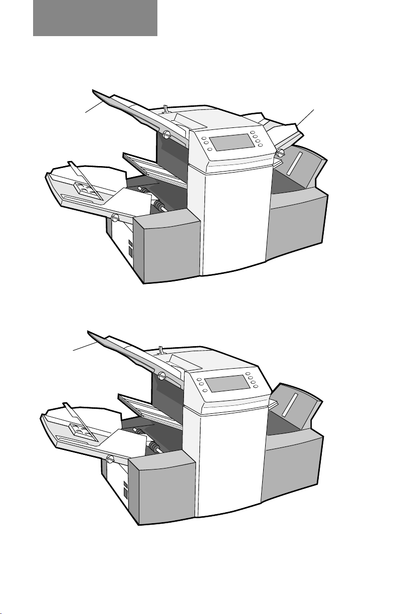
Three-Station Model
This model incorporates two sheet feeders and an insert feeder.
It is the only model that has OMR and has the most setup
options. For this reason, all illustrations in this guide show this
model.
Sheet
Feeder 1
Sheet
Feeder 2
1-1
Insert Feeder
Page 10
Introduction
Two-Station Model
This model incorporates a single sheet feeder and an insert
feeder.
Insert Feeder
Sheet Feeder 1
One-Station Model
This model incorporates a single sheet feeder.
Sheet Feeder 1
All models are set up and operated in a very similar way.
Procedures in this guide cover all models. If a function is
model dependent, the accompanying text will explain this.
1-2
Page 11

Introduction
Safety
Safety Precautions:
When using this machine, follow the normal safety precautions for all
office equipment:
Keep loose clothing, jewelry and long hair away from all moving parts.
Avoid touching moving parts or materials while the machine is in use.
Before clearing a jam, be sure machine mechanisms come to a stop.
When removing jammed material, avoid using too much force to
protect against minor personal injury and damaging equipment.
Use the power cord supplied with the machine and plug it into a
properly grounded wall outlet located near the machine and easily
accessible. Failure to properly ground the machine can result in severe
personal injury and/or fire.
The power cord wall plug is the primary means of disconnecting the
machine from AC supply.
DO NOT use an adapter plug on the line cord or wall outlet.
DO NOT remove the ground pin from the line cord.
Avoid using wall outlets that are controlled by wall switches, or shared
with other equipment.
DO NOT route the power cord over sharp edges or trapped between
furniture.
Insure there is no strain on the power cord where it becomes jammed
between the equipment, walls or furniture.
Be certain the area in front of the wall receptacle into which the
machine is plugged is free from obstruction.
Do not remove covers. Covers enclose hazardous parts that should
only be accessed by Pitney Bowes Customer Service. Report any
damage of covers to a Pitney Bowes Customer Service Representative.
To prevent overheating, do not cover the vent openings.
Read all instructions before attempting to operate the equipment.
Use this equipment only for its intended purpose.
In addition, follow any specific occupational safety and health
standards for your workplace or area.
1-3
Page 12
Introduction
Machine Identification
12
2
1 6
11
3
5
9
1 Sheet Feeder 1
This feeder is intended for feeding material that requires
folding. If you are running addressed documents for
insertion into window envelopes, feed them from this
feeder.
8
13
4
10
7
In addition, sheet feeder 1 can be set to ‘manual feed’. In
this mode, stapled sets of up to 5 sheets may be run. The
machine waits for each set to be manually fed into sheet
feeder 1 before folding and inserting the set automatically. See the specifications section of Chapter 6
(Reference) for full details of the sets possible.
2 Sheet Feeder 2
For feeding material that requires folding. Its functions
are similar to sheet feeder 1 but ‘manual feed’ is NOT
available from this feeder.
(three-station machine only)
1-4
Page 13

Introduction
3 Insert Feeder
Use this feeder to add additional inserts to your
envelope. Material fed from this feeder cannot be folded
by the inserter. However, this feeder is especially suited
to feeding pre-folded or thicker inserts.
4 Fold Plate 2
5 Fold Plate 1
These units are used to create the desired fold in
material fed from the sheet feeder(s). The fold plates are
automatically set from the control panel.
6 Display/Control Panel
This is where you enter commands and where the
machine informs you of its status with the use of symbols
and icons. Full details of each button function are given
on the following page.
7 Stacker and Measuring Scale
Located at the right end, is the fold-down stacker. This
unit can be latched against the right side of the machine
when not in use to save space.
(two and three-station machines only)
A scale is located along the front edge of the stacker to
aid measurement of material and envelopes.
8 Hand Crank
The hand crank is located behind a drop down cover at
the left front. It can be used to manually turn the machine
mechanisms to free a material stoppage.
9 Envelope Feeder
This feeder feeds envelopes into the inserting area
where they are filled with the sheets requested from the
other feeders.
10 Envelope Inverter Unit
This unit exits the envelope into the stacker face up.11
1-5
Page 14
Introduction
11 Sealer Water Bottle
The sealer water bottle is located behind a drop down
cover at the right rear of the machine. It provides water or
EZ Seal® solution to the envelope sealer unit.
12 Upper OMR Scanner
Scanner used to read OMR marks on sheet feeder 1 from
above the sheet.
13 Lower OMR Scanner
Scanner used to read OMR marks on sheet feeder 2 from
under sheet.
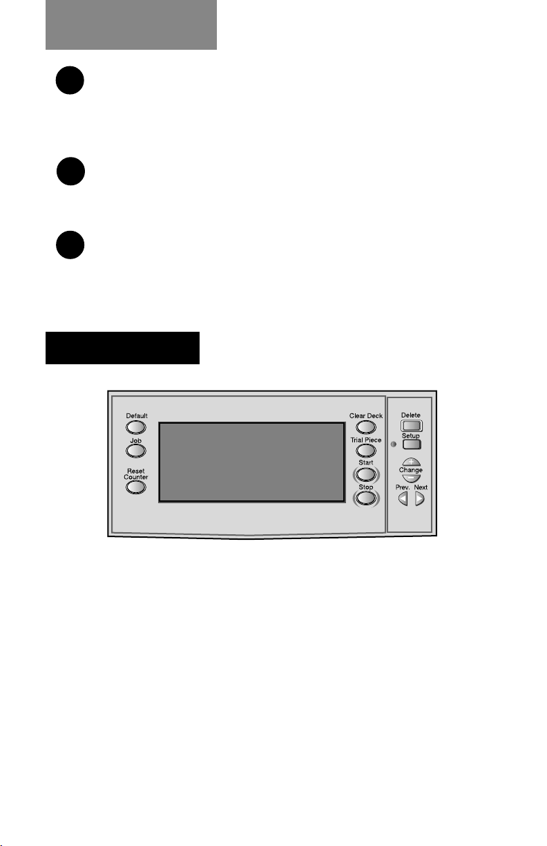
Control Panel
(three-station machine only)
(three-station machine only)
Control Panel Buttons
Default Press this button to return the system to its
‘standard’ settings. These settings come preconfigured from the factory but can be modified to
suit your needs by a Pitney Bowes Customer Service
Representative.
Job Press to step through the jobs you have programmed
into the machine’s memory. Up to twenty (20) jobs can
be held, depending on model (see page 2-9). See
Chapters 3 or 5 for details on programming jobs.
1-6
Page 15

Introduction
Reset Counter Press this button to reset the item counter.
Clear Deck Pressing this button will jog material through and out
of the machine. It can be used to clear the machine
ready for automatic operation after a stoppage has
occurred etc.
Trial Piece This button is used to run a single test piece so that
you can check machine setup. A trial piece must be
run before automatic operation can be commenced
using the Start button. If double detection is in use,
the machine sets itself automatically as it runs the
trial piece. This envelope will be unsealed and
counted as one item.
Start Starts automatic operation.
Stop Stops automatic operation at the end of the next
cycle.
Delete Used in setup mode to delete a programmed job
from memory.
Setup When pressed, the machine enters setup mode. This
mode allows you to program jobs into memory for
instant recall using the Job button.
Change + – In setup mode, used to select options or set values
of machine settings.
Prev. In setup mode, used to step backwards/forwards
Next
through the various machine settings.
1-7
Page 16
Introduction
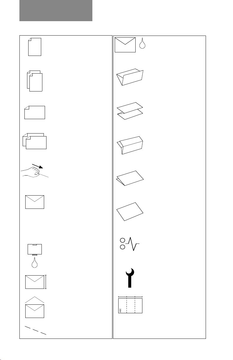
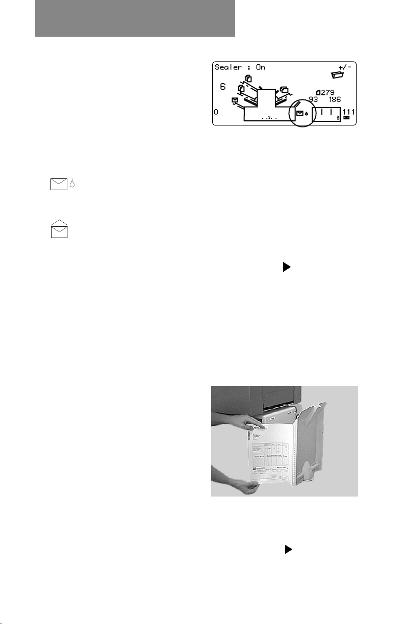
Display Symbols
. . 3 . .
Used on sheet feeders to
signify that the feeder is
on without double
detection.
Used on sheet feeders to
signify that the feeder is
on with double detection.
Used on insert feeder to
signify that the feeder is on
without double detection.
Used on insert feeder to
signify that the feeder is
on with double detection.
Used on sheet feeder 1 to
signify that the feeder is
set for manual feed.
Used on envelope feeder
to signify that the feeder is
on.
Indicates the setting (from
1 to 5) of the envelope
stop.
Indicates that the sealer
water bottle needs refilling.
Indicates that the sealer
unit is on (automatic
envelope sealing).
Indicates a ‘C’ - Letter
fold is selected.
Indicates a ‘Z’ -
Accordion fold is
selected.
Indicates a double fold
is selected.
Indicates a single fold is
selected.
Indicates a no-fold insert
operation.
Indicates a material
stoppage. The position of
this symbol in the display
indicates where the
stoppage has occurred.
Indicates the envelope
depth.
Indicates that the sealer
unit is off (envelopes not
sealed).
Used on any feeder to
indicate feeder is not in use.
Call Pitney Bowes
Service.
Indicates the paper size,
address orientation and
fold(s) set for sheet
feeder.
1-8
Page 17
Operation
2. OPERATION
This section explains operation of the DI350 inserter, assuming the job to be run is already programmed into the machine.
If the job has not been programmed, refer to “Create Non-
OMR Job” on page 3-1 or “Create OMR Job” on page 5-1.
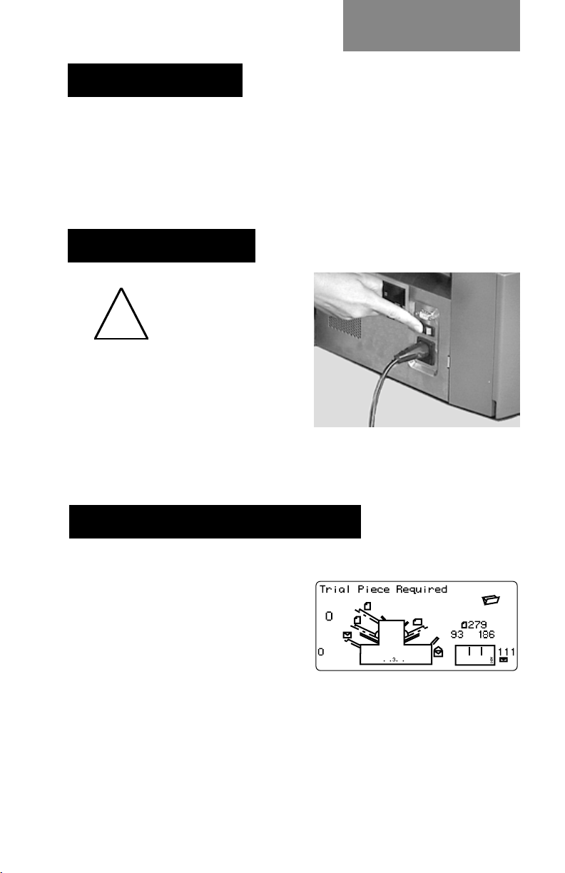
Connecting Power
Read the safety
information on
!
Connect the power cord to
the socket on the left side of
the machine. Plug the power
cord into a suitable power
outlet. Make sure the power outlet is near the machine and is
easily accessible. Turn the machine power switch ON.
page 1-3 before
connecting the
machine.
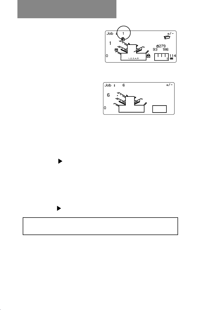
Selecting and Running a Job
Select the Job
When the machine is turned
ON, the display will show the
last job run and ‘Trial Piece
Required’.
Press the Job button until the
job you require is displayed,
or press Default if you want to run the machine with your
‘standard’ settings.
Note: The default job can be altered only by a Pitney Bowes
Customer Service Representative.
2-1
Page 18
Operation
If you have material loaded,
press Trial Piece. The
machine will set itself and
run a test piece for you to
check.
If you don’t have material loaded, do this now, then return to
this section. Loading feeders etc. is covered on the following
pages.
Note:
You may have selected a
‘manual feed’ job where
sheet feeder 1 is set for
manual feed of collated sets.
If this is the case, the sheet
feeder should not be loaded,
as the collated sets are fed
one at a time as required by
the machine. However, the
lever shown in the illustration should be pulled back to open
the feed mechanism to ready the manual feed operation.
Remember to return this lever to its normal position when
you use the feeder for automatic operation.
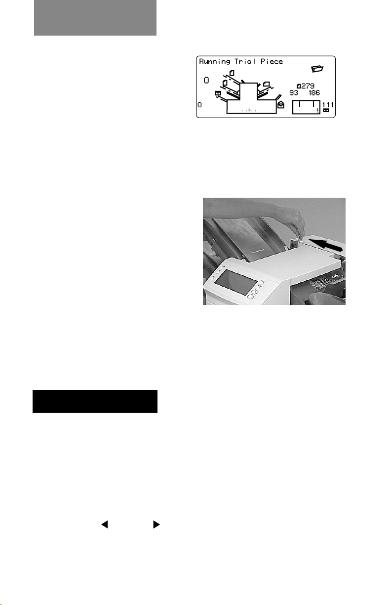
Run a Trial Piece
Once material is in place, press Trial Piece so you can
check that the setup is correct.
Note: In switchable mode both sheet feeders must be loaded. A
trial piece will be run for both feeders.
Minor changes to the job settings can be made at this stage
if the trial piece needs ‘fine tuning’. Press Setup, then use
the Prev ( ), Next ( ) and Change (+/-) buttons as
required to modify job settings. When you have made the
necessary changes, press Setup again to return to run
mode. The job will be saved with the new settings.
2-2
Page 19
Operation
Start Machine Operation
Press Start to begin automatic operation. The machine will
operate until either material runs out or the Stop button is
pressed.
Note: If the three station machine is set for switchable
feeding, the display will show:
Ready: 1 > 2 > 1
This confirms that feeding will automatically switch between
sheet feeders. See page 3-8 or 5-7 for more details.
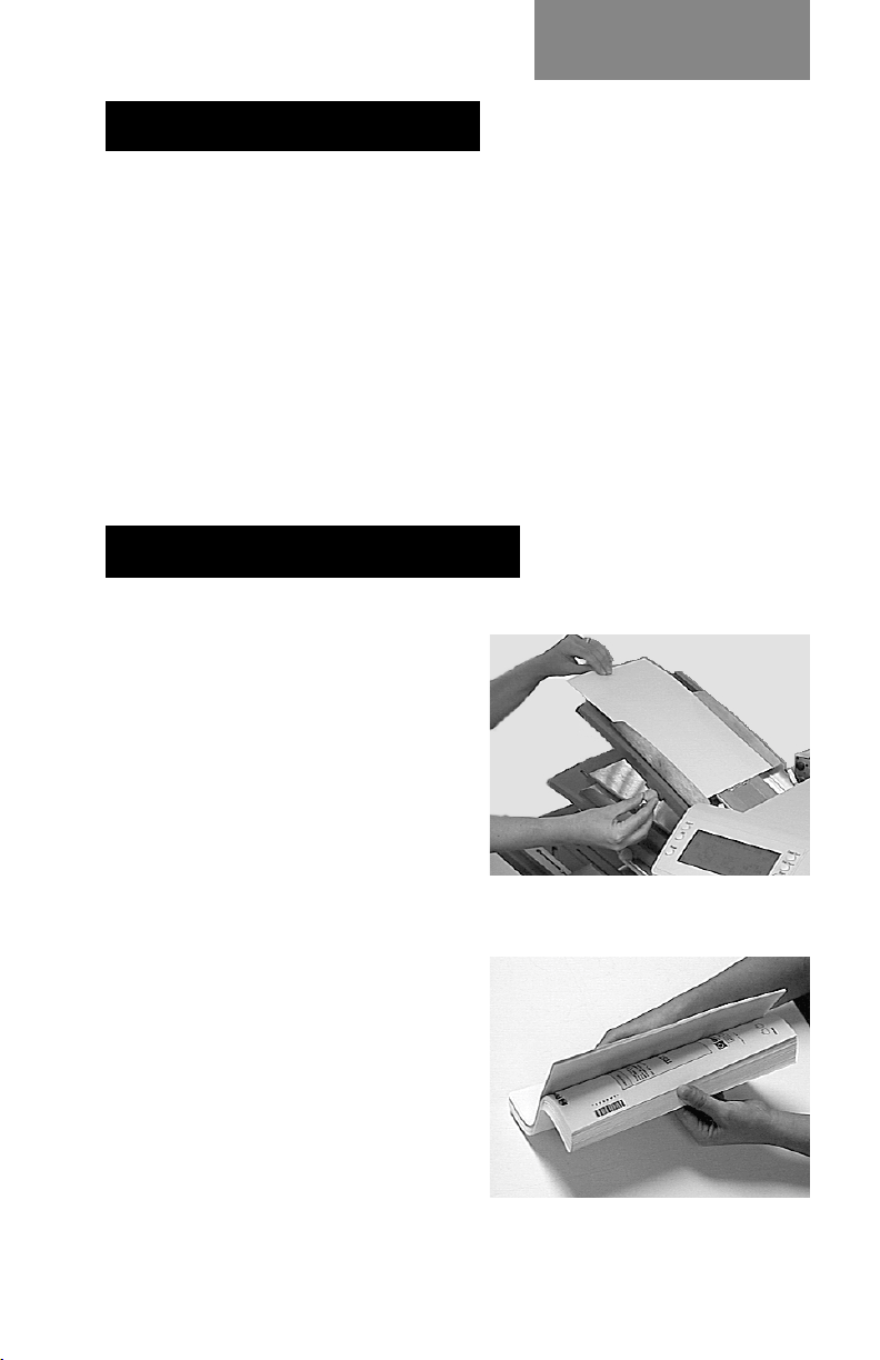
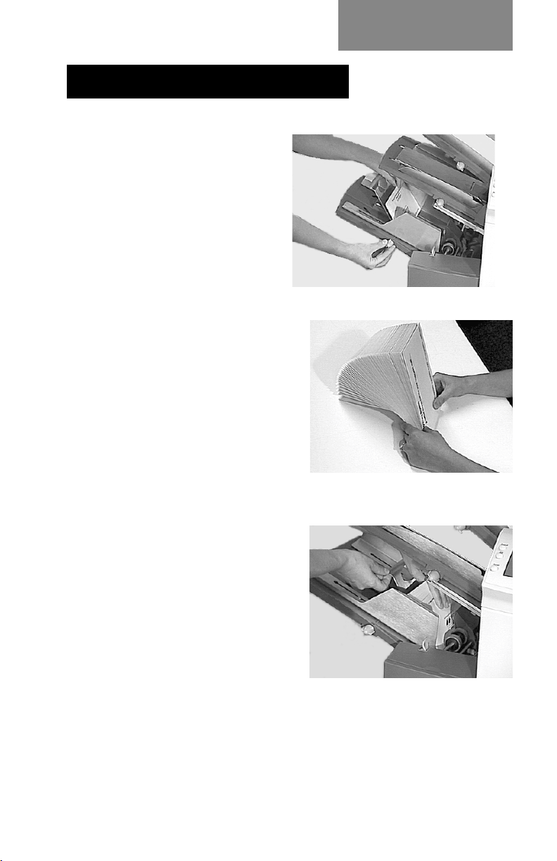
Setting the Sheet Feeders
1. Adjust the side guides to
the width of the material
being fed, then back-off a
quarter turn on the side
guide control. This will
set the correct clearance
between the guides and
the material.
2. Take the stack of paper
and aerate it to ensure
the individual sheets are
not stuck together.
2-3
Page 20
Operation
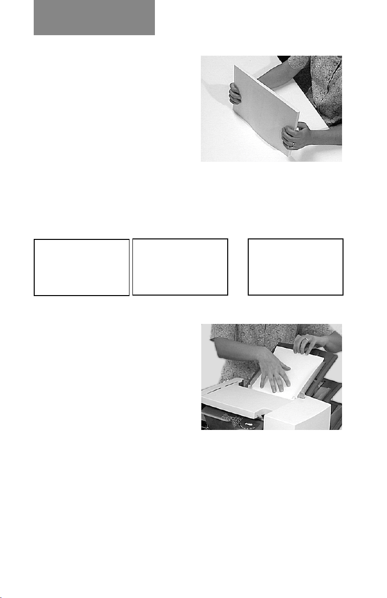
3. Jog the stack back into
alignment. The sheet
feeders take the paper
stack aligned in a similar
way to a photocopier
paper cassette.
4. The three possible
choices for loading you documents with addresses are
listed below. NOTE: The display will indicate the correct
orientation of the paper in the first two cases only.
FACE UP
HEAD FIRST
ABC
FACE DOWN
FEET FIRST
ABC
ABC
FACE UP
FEET FIRST
5. Place the paper stack onto
the feed deck. Allow the
deck to move down and
the top of the paper stack
to slide under the feed
roller.
Note: When using both
sheet feeders with
accordion
fold, sheet
feeder 2 must be used for
the prime (address bearing)
document.
6. You can pull out the sliding supports from the end of the
deck to help support long material.
2-4
Page 21
Setting the Envelope Feeder
1. Adjust the side guides
to the width of the
envelopes being fed,
then back-off half a
turn on the side guide
control. This will set
the correct clearance
between the guides
and the envelopes.
2. Aerate the stack of
envelopes to be run.
Operation
3. Place them on the feed
deck with the flaps up
and trailing. The lead
edge of the first
envelope should be
under the front feed
roller.
Let the ‘wedge’ slide
down behind the stack so
that the envelopes are
supported.
2-5
Page 22
Operation
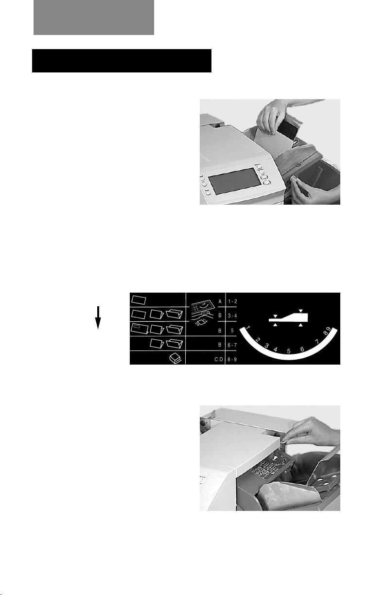
Setting the Insert Feeder
1. Adjust the side guides to
the width of the material
being fed, then back-off a
quarter turn on the side
guide control. This will
set the correct clearance
between the guides and
the material.
2. Refer to the ‘label’
located on the insert
feeder. Compare your insert with the diagram. Read off
the settings for the insert feeder blue lever (numbers 1 to
9) and the separator shield (letters A to D).
Thin Material
Thicker Material
Thick Inserts/
Booklets etc.
3. Set the blue lever to the
number required.
2-6
Page 23
4. Set the separator shield
to the letter required.
5. Fan the inserts to be run
and place them onto the
feed deck face up with
their bottom edge feeding
first.
Operation
Let the ‘wedge’ slide
down behind the stack so
that the inserts are
supported.
2-7
Page 24

Operation
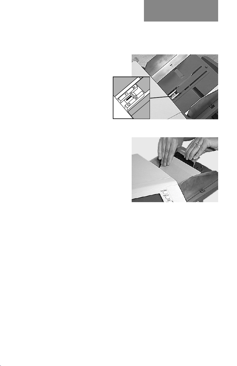
Filling the Sealer
When the sealer unit needs refilling, the Add Fluid symbol
will flash in the display.
Add Pitney Bowes EZ Seal®
solution or water in the
following way:
Note: EZ Seal® solution is
recommended to minimize
growth of algae and scale
build-up.
Hinge open the Water Bottle
Cover located at the rear right hand side of the machine.
Remove the bottle
Fill the bottle up to the level indicated.
Replace the water bottle and close the cover.
If the sealer unit has been allowed to completely empty, you
should allow time for water to soak through the sealer
mechanism.
2-8
Page 25

Operation
Programming Options By Model
The DI350 has the ability to be programmed by the operator
with up to 20 jobs (depending on model) which can be recalled
at the touch of a button. The following table shows which
functions are available on a machine by the number of stations
it has (
✓ = present on machine):
Function
Sheet Feeder 1 ✓✓✓On (with double detect), On (without
Insert Feeder ✓✓On (with double detect), On (without
Sheet Feeder 2 ✓ On (with double detect), On (without
Accumul Mode ✓✓✓Off or On (with 2, 3,4, or 5 pages)
OMR Mode ✓ Off, On, OMR + Sequence, OMR +
Mode ✓✓✓Insertion Mode, Fold Only Mode
Number of Jobs 10 10 20 Each job can be programmed by operator
Fold Type ✓✓✓C - Letter, Z - Accordion, Double or
Paper Length ✓✓✓any within machine specification limits
Fold A ✓✓✓any within machine/fold specification
Fold B ✓✓✓any within machine/fold specification
Envelope Depth ✓✓✓any within machine specification limits
Envelope Stop ✓✓✓1 to 5
Batch Mode ✓✓✓Off or On (from 50 to 99)
# of Stations
1 2 3
Possible Settings
double detect), Off, or Manual Feed
✓ In addition to above: Select Feed (with
double detect), or Select Feed (without
double detect)
double detect), Off
✓ In addition to above: Select Feed (with
double detect), or Select Feed (without
double detect)
double detect), Off, Select Feed (with
double detect), or Select Feed (without
double detect)
Select Feed and Sequence, OMR +
Select Feed
Single
limits
limits
2-9
Page 26

Operation
2-10
Page 27
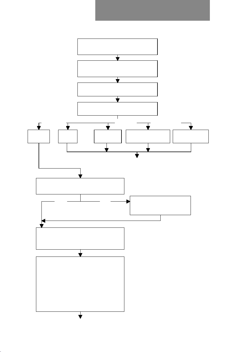
Create Non-OMR Job
3. CREATE NON-OMR JOB
This section takes you step-by-step through the process of
setting up a new (non-OMR) job and saving it in the memory.
Programming is carried out in the ‘Setup Mode’…
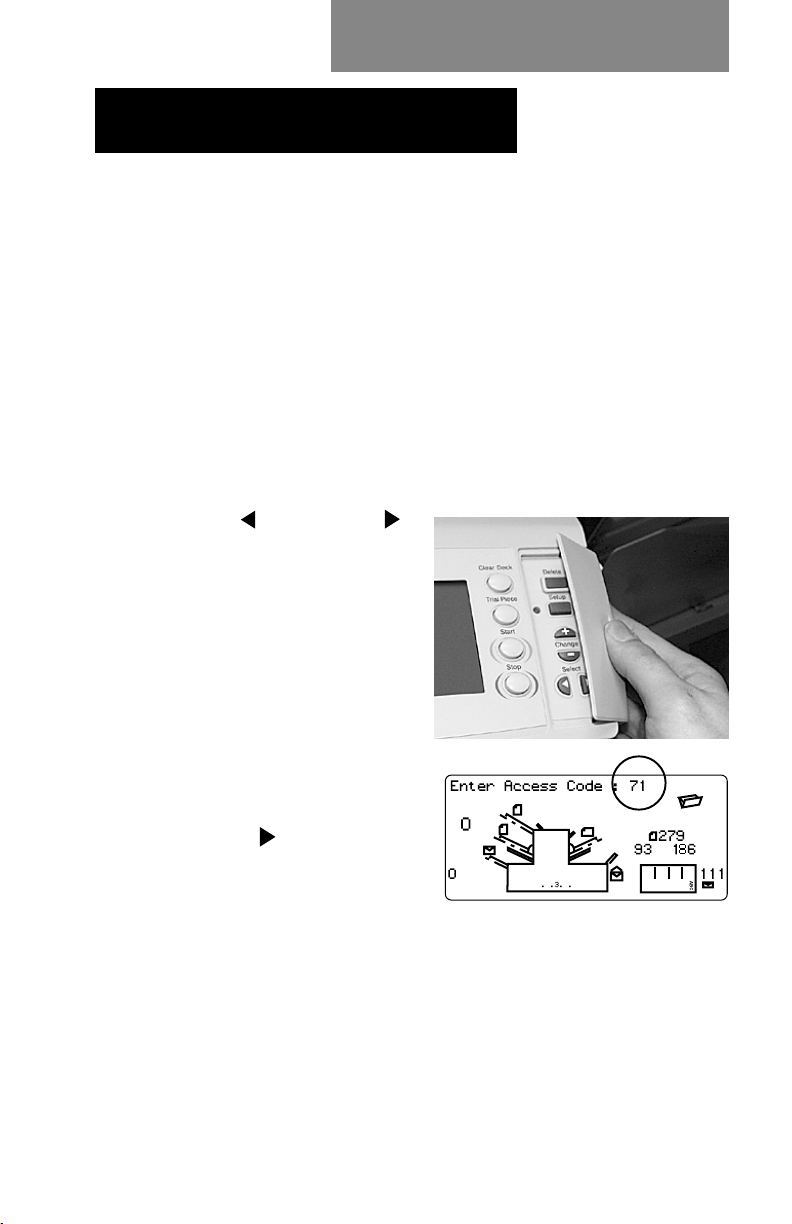
Entering the Setup Mode
Open the hinged cover to the right of the display. This will
expose the setup buttons.
Press Setup. The indicator will light and the machine will ask
for an access code. This code prevents the machine’s
settings being changed by unauthorized personnel.
The Prev (
buttons are used to step
forward or backwards through
the settings available. Once
the item is displayed, the
Change (+/-) buttons are
used to select the option or
value you want.
Use the Change (+/-) buttons
to select the access code 71.
Press Next (
to the next setting….
) and Next ( )
) to advance
3-1
Page 28
Create Non-OMR Job
Choosing the new job number
The machine will ask for the
job number you wish the new
settings to be stored under
(the default job number is 1).
Use the Change (+/-) buttons
to display the job number you want.
Notes:
• If you use an existing job
number, the old settings
will be overwritten by the
new settings you are
about to make.
• If you want to find a
currently unused job number, press Change (+/-)until you
see a job where the display shows no symbols alongside
the feeders or in the fold setup area. This means the job
is currently empty.
Press Next (
) to advance to the next setting…
Selecting Non-OMR Option
Press Change (+/-) until you see this option:
OMR off
Press Next (
The flowchart on the following pages describe the setup for a
non-OMR job.
OMR is turned off for this job.
) to advance to the next setting... (see page 3-5)
3-2
Page 29
Create Non-OMR Job
Flowchart for Non-OMR Job Setup
Open hinged cover on right side of
control panel and press Setup key
Use + / - keys to enter 71 for
access code, then press > key
Use + / - keys to enter job number,
Base Level Enhanced
OMR off OMR on
Use + / - keys to select accumulation
Off or On, then press > key
Use + / - keys to select fold type
(c-letter, z-accordion, double, single),
then press > key
then press > key
Use + / - keys to select OMR
function, then press > key
OMR +
Sequence
OnOff
Level Only
OMR + Select
Feed + Sequence
See Separate
Flowchart for
OMR Job
Use + / - enter keys to
select 2, 3, 4 or 5 pages,
then press > key
OMR + Select
Feed
Use + / - keys to select whether the
main sheet feeder is:
• On Double Detect
• Manual Feed
• On
• Off
• Switchable - On Double Detect
• Switchable - On
then press > key
continued on next page
3-3
Page 30
Create Non-OMR Job
Flowchart for Non-OMR Job Setup
continued from previous page
Use +/ - keys to select whether other
sheet feeder is Off, On with
double detect or On with no double
detect, then press > key
Use + /- keys to select whether insert
feeder is Off, On with
double detect or On with no double
detect, then press > key
Insert Feeder On
Use +/ - keys to select whether sealer
is Off or On, then press > key
Use +/ - keys to change paper length of
your sheets, then press > key
Use + /- keys to change Fold A setting
(if neccesary), then press > key to
continue
Single Fold
Use +/ - keys to change envelope depth,
then press > key
Insert Feeder Off
C, Z, Double Folds
Use +/ - keys to select
whether insert feeder is in
insertion mode or fold only
mode, then press > key
Use +/- keys to change Fold B
setting (if neccesary), then
press > key to continue
continued on next page
3-4
Page 31

Create Non-OMR Job
Flowchart for Non-OMR Job Setup
continued from previous page
Use +/ - keys to change envelope stop
setting, then press > key
Use +/ - keys to select whether batch
mode is Off or On, then press > key
Use +/ - keys to enter batch
Batch OnBatch Off
Job number displays (back at beginining)
Setting the Accumulation Function
Press Change (+/-) until you see the option you want:
counter (from 50 to 999),
then press > key
Accumulation: OFF
Accumulation is turned off for
this job.
Accumulation: ON
Accumulation is turned on for
this job.
Accumulation = 2/3/4/5
Select how many pages you want to
feed into each envelope. Either 2, 3, 4 or 5 pages can be
selected.
Press Next (
) to advance to the next setting…
3-5
Page 32
Create Non-OMR Job
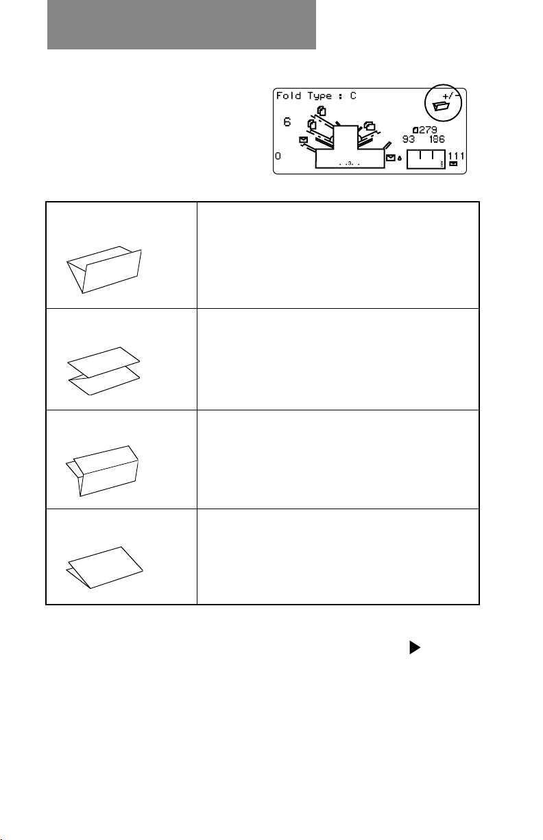
Fold Type
Select the type of fold.
Press Change (+/-)
until you see the option
you want:
C - Letter
Z - Accordion
Double
Single
Folds your sheet into a standard ‘C’
or letter fold.
Folds your sheet into a ‘Z’ or
accordion fold.
Folds your sheet in half and then in
half again.
Folds your sheet once.
When the fold type is set as required, press Next ( ) to
advance to the next setting…
3-6
Page 33

Create Non-OMR Job
Setting Sheet Feeder 1 (Upper Feeder)
Select whether you want to use sheet feeder 1 and, if so,
how it will be used.
Press Change (+/-) until you see the option you want:
On Double Detect
On
Manual Feed
Off
Switchable: On
Switchable: On Dble Detect
Feeder on with the double
detector operating. (The double
detector stops the machine if
more than one sheet
simultaneously feeds from the
feeder).
Feeder on without the double
detector.
Allows you to manually feed
collated sets (see notes below).
Feeder turned off for this job.
These functions are available only
on the three-station machine.
Feed will initially be from Sheet
Feeder 1. When the feeder is
empty, the machine will
automatically switch to feeding
from sheet feeder 2.
When a trial piece is requested,
both feeders must be loaded as a
trial piece will be fed from each
feeder
Notes About Manual Feed:
1. The manual feed setting allows stapled sets of up to 5 sheets
of 20/24 lb (to a maximum of 120 lbs per set) to be run. The
maximum compressed thickness of the set
not exceed 2mm. The machine will wait for manual insertion of
each set into sheet feeder 1 after which it will fold and insert
the set automatically.
2. When running manual feed mode, sheet feeder 2 becomes
inoperable
3-7
after folding
must
Page 34

Create Non-OMR Job
When sheet feeder 1 is set as required, press Next ( ) to
advance to the next setting…
Setting Sheet Feeder 2 (Lower Feeder)
Select whether you want to
use the sheet feeder 2. This
function is available only on
the three-station model.
Press Change (+/-) until you
see the option you want:
On Double Detect
On
Off
Feeder on with the double detector
operating. (The double detector
stops the machine if more than
one sheet simultaneously feeds
from the feeder).
Feeder on without the double
detector.
Feeder turned off for this job.
When sheet feeder 2 is set as required, press Next ( ) to
advance to the next setting…
3-8
Page 35

Create Non-OMR Job
Setting Insert Feeder
Select whether you want to use the insert feeder and, if so,
how it will be used. This function is available only on the two
and three-station models.
Press Change (+/-) until you see the option you want:
On Double Detect
On
Off
Feeder on with the double detector
operating. (The double detector
stops the machine if more than
one insert simultaneously feeds
from the feeder).
Feeder on without the double
detector.
Feeder turned off for this job.
When the insert feeder is set as required, press Next ( ) to
advance to the next setting…
Mode
This option only appears if you have the insert feeder turned
off. In this case, the machine needs to know if the job
requires inserting into an envelope or if it is a fold only job.
If the insert feeder has been set to ‘on’, the machine
automatically sets itself to Insertion Mode and advances to
the Sealer option on the next page.
If ‘Insertion Mode’ appears on the display, you must choose
the machine’s mode of operation. Press Change (+/-) to
switch between the options:
Insertion Mode
Fold Only Mode
Activates the Envelope Feeder for a normal
inserting job.
Turns the Envelope Feeder off and makes the
machine act as a folding machine.
When the mode is set as required, press Next ( ) to advance
to the next setting…
3-9
Page 36
Create Non-OMR Job
Sealer
This setting only appears if an
insertion mode has been
selected.
Select whether you want to seal
envelopes or not.
Press Change (+/-) to switch the option on or off:
On
Off
Turns the sealer unit on for automatic sealing of
envelopes. Make sure the sealer water bottle is full
of EZ Seal® or water (see page 2-8).
Turns the sealer unit off. Envelopes will be ejected
unsealed.
When the sealer is set as required, press Next ( ) to advance
to the next setting…
If you have selected either of the sheet feeders, the next
setting offered will be fold type. However, if you are using the
insert feeder only, folding is not possible and the machine will
advance directly to the envelope depth setting (page 3-12).
Paper Length
Select the paper length.
Use the scale on the edge of
the stacker.
Quick reference:
US Letter length 11" (279mm)
A4 paper length 297mm
Press Change (+/-) until the length of your paper (in
millimeters) is displayed.
When the paper length is correct, press Next (
) to advance
to the next setting…
3-10
Page 37

Create Non-OMR Job
Fold A
Select the size of the first
fold required.
Depending on the settings
previously made for fold type
and paper length, the machine will be suggesting the correct
dimension for the first fold. Most times, therefore, this setting
will not require alteration.
If you want to change the ‘standard’ setting, press Change
(+/-) until the length of fold required is displayed. The symbol
| –––– | shows the fold panel
you are adjusting.
The machine will
automatically limit your
choices to what is physically
possible within the machine
specifications. (As you change the length of fold A, you will
see the dimension of fold B automatically changing to keep
within paper length and machine specifications.)
When the setting is correct, press Next (
the next setting…
) to advance to
Fold B
Select the size of the second
fold required.
In a similar way to fold A, the
machine will be suggesting
the correct dimension for the
fold.
If you want to change the ‘standard’ setting, press Change
(+/-) until the length of fold required is displayed. The symbol
| –––– | shows the fold panel you are adjusting.
When the setting is correct, press Next (
next setting…
3-11
) to advance to the
Page 38

Create Non-OMR Job
If you are programming an inserting job the setting Envelope
Depth will now appear. If you are programming a fold only
job, the display will jump straight to the ‘Confirming the Job
Setup’ section on the next page.
Envelope Depth
Select the depth of your envelopes (in millimeters).
Again, you can use the
scale on the stacker to
measure the depth of your
envelopes. Press Change
(+/-) until the correct
dimension is displayed.
When the envelope depth is
set as required, press Next (
setting…
Envelope Stop
Select the position of the machine’s envelope stop.
) to advance to the next
The stop has five positions
numbered 1 to 5. Setting 3 is
the ‘standard’ setting for
normal weight paper with
standard folds. A thinner/
lighter envelope will require a
lower setting and thicker/heavier envelope a higher setting.
Press Change (+/-) until the setting you want is displayed.
When the envelope stop is set as required, press Next (
advance to the next setting…
3-12
) to
Page 39

Create Non-OMR Job
Batch Mode
The batch mode allows you to automatically process predefined batches of finished mailpieces. The system “counts
down” from the number programmed for that job. When the
batch is complete (has reached “0”), the machine will stop,
allowing you to empty the stacker. Pressing Start will
commence processing of the next batch.
If batch mode is not selected, the display counter will simply
count the number of items processed until reset by pressing
Reset Counter.
Press Change (+/-) to switch
batch mode On or Off.
When the setting is correct,
press Next ( ).
If batch mode is turned On,
the machine will now request
the batch quantity. The
default quantity is 50, but you
may select any value up to
999 using the Change (+/-) buttons.
When the setting is correct, press Next (
).
Confirming the Job Setup
Job setup is now complete.
The display will show the
complete job setup for you to
confirm. If you see a setting
that is incorrect, use the Prev
( ) button to backtrack to
the setting and correct it.
When you are satisfied with the program, press the Setup
button. The machine will save the job into its memory and
reset to the new job.
3-13
Page 40

Create Non-OMR Job
When this is complete, the
display will show the new job
with the message ‘Trial Piece
Required’.
Job settings will be retained by the machine
disconnected
until they are changed or deleted as described
even with power
on the following page.
Testing the Job
Load material and press Trial Piece so that you can check
that the setup is correct.
Minor changes to the job settings can be made at this stage
if the trial piece needs ‘fine tuning’. Press Setup, then use
the Prev (
), Next ( ) and Change (+/-) buttons as
required to modify job settings. A chart is provided below to
help ‘fine tune’ your fold settings.
FOLD TYPE ADDRESS TOO LOW ADDRESS TOO HIGH
“C” - Letter Fold Decrease Fold A Increase Fold A and
increase Fold B by the
same amount
“Z” - Accordion Increase Fold A Decrease Fold A and
Fold increase Fold B
by the same amount
Single Fold Increase Fold A Decrease Fold A
Double Fold Decrease Fold A Increase Fold A
It is recommended that the folds are changed by 5mm each
time and a new trial piece run to test the settings. When you
have made the necessary changes, press Setup again to
return to run mode. The job will be saved with the new
settings.
3-14
Page 41

Create Non-OMR Job
Changing an existing job
To change an existing job…
1. Enter the setup mode as described on page 3-1.
2. Use the Change (+/-) buttons to display the job you wish
to edit.
3. Use the Prev (
setting(s) you wish to change.
4. Use the Change (+/-) buttons to change the options/
dimensions you wish to amend.
5. Press the Setup button to leave setup mode and save
the changes.
) and Next ( ) buttons to display the
Deleting a job
To erase an existing job from memory, follow the steps
below:
1. Enter the setup mode as described on page 3-1.
2. Use the Change (+/-) buttons to display the job you wish
to delete.
3. Press the Delete button. The display reads “Press again
to confirm”. Press Delete again. The display will briefly
read ‘Deleting Job’ as the job is erased.
4. Press the Setup button to leave setup mode.
3-15
Page 42

Create Non-OMR Job
3-16
Page 43

What is OMR?
4. WHAT IS OMR?
DI350 inserters that are 3-station models have an Optical
Mark Recognition (OMR) scanner installed on the upper and
lower sheet feeders. This section describes what OMR is and
how it can be used to enhance your use of the machine for
your inserting needs. Once you understand the OMR concepts (and you have printed your documents with the proper
OMR marks), go to Chapter 5 for instructions on setting up
an OMR job and adjusting the OMR scanners.
What is OMR (Optical Mark Recognition)?
OMR (Optical Mark Recognition) is a system whereby marks
are pre-printed on all pages that make up a document,
statement, advertisement, etc. These pages are fed into the
machine and their OMR marks “read” by the system, whose
job is to interpret the marks and do the prescribed tasks
associated with those marks (such as feeding sheets or
verifying the end of a document).
The tracking of these OMR marks by the system assures that
sheets of a document which belong together (a collated set)
actually stays together throughout the inserting process. This
is known as
are printed and read, the better the collated set integrity.
However, more space and programming is required to print
additional marks on a document, so you will need to weigh
the trade-off between more integrity and the space you have
available on your document.
The OMR mark itself is normally a dark solid line on a sheet
of light-colored paper (usually white) that is horizontally
positioned so it matches the direction of travel of the paper.
This line must be printed to certain specifications in width,
length, and separation to be read by the OMR scanner on the
system. Normally, there are several of these OMR marks
printed in a group in one area on the paper (away from any
text, pictures, or other lines) where the OMR scanner “reads”
or scans them.
collation set integrity
4-1
. The more OMR marks that
Page 44

What is OMR?
What Do OMR Marks Look Like on Paper?
The example below shows OMR marks that may be typically
used on a document for the DI350:
Example of OMR Marks on a Document (not drawn to scale)
Feed Direction
(for this example)
OMR Marks
This is a test last page for a collation. This is a test page for a
{
collation. This is a test page for a collation.
This is a test page for a collation. This is a test page for a
collation. This is a test page for a collation.
This is a test page for a collation. This is a test page for a
collation. This is a test page for a collation. This is a test page
for a collation. This is a test page for a collation. This is a test
page for a collation.
This is a test page for a collation. This is a test page for a
collation. This is a test page for a collation.
This is a test page for a collation. This is a test page for a
collation. This is a test page for a collation.
This is a test page for a collation. This is a test page for a
collation. This is a test page for a collation. This is a test page
for a collation. This is a test page for a collation. This is a test
page for a collation.
Sincerely,
John Smith,
Solicitor General
OMR Marks Being Read by a DI350 Scanner
4-2
Page 45

What is OMR?
How are OMR Marks Read on the DI350?
There are two OMR scanners (the devices that “read” the
OMR marks) on the DI350 inserter. One is top-mounted on
sheet feeder 1 and the other is bottom-mounted on the sheet
feeder 2 (see figures below).
Top-Mounted
OMR Scanner on
Sheet Feeder 1
(upper)
BottomMounted OMR
Scanner on
Sheet Feeder 2
(lower )
4-3
Page 46

What is OMR?
The top-mounted scanner reads the marks from on top of the
sheet, while the bottom-mounted scanner reads the marks
from underneath the sheet of paper. This configuration allows
you the maximum flexibility for your document folding needs
when processed through the system. Specifically:
• the top-mounted scanner supports C-fold and double fold
documents so the address can be visible in window envelopes
• that bottom-mounted scanner supports Z and half-fold
documents so the address can be visible in window envelopes
How are OMR Marks Generated?
There are several ways to print the special OMR marks on a
document. Pitney Bowes offers a PC-based product called PB
FIRST™ that enables you to add the OMR marks to your
documents so they can be read by the DI350 inserter (it also
allows you to setup OMR marks for the DI400 and DI800
inserters). What’s nice is that once you’ve setup PB FIRST™
correctly to generate the marks, the marks are printed to the
proper specifications – no “experimentation” is necessary.
If you have a computer/IT department in your organization, you
may be able to use them also as a resource to create and print
the OMR marks for you, based on the DI350 OMR specifications given in this chapter (see pages 4-25 and 4-26).
Additional information on implementing OMR marks can be
found in Pitney Bowes publication SV40193 and the OMR
template that are included with your DI350 inserter.
IMPORTANT: Unless you (or your organization) has had
previous experience working with OMR marks or PB FIRST™,
we recommend that you have a Pitney Bowes Consultant
setup your OMR marks for you (at a cost to be estimated).
Pitney Bowes does not cover the implementation of OMR
marks on your documents under the standard support
agreements for the DI350 inserter.
4-4
Page 47

What is OMR?
What OMR Marks are Used on the DI350?
The DI350 has two feature levels of OMR – the feature level
you have depends on the level installed on your machine.
Basic Level OMR
the ability to have variable-sized collation sets (a different
number sheets may be fed for each document based on
what the marks on those sheets indicate to the system). It
consists of these marks, known as Group 1:
Group 1 (“OMR”)
• Benchmark
• Safety
• Not EOC (end-of-collation)
• Not BOC (beginning-of-collation)
• Parity [even]
• Retime Mark
Enhanced Level OMR
size collation sets as well as greater collation set integrity.
The Enhanced OMR Level allows for two additional groups of
marks, which consist of:
Group 2 (“Select Feed”)
• SF1 (feed from the other sheet feeder)
• SF2 (feed from the insert feeder)
• Auto-Batch
• Retime Mark
– provides basic collation set integrity and
– allows more flexibility in variable-
Group 3 (“Sequence”)
• WAS3 (wrap-around sequence)
• WAS2 (wrap-around sequence)
• WAS1 (wrap-around sequence)
• Retime Mark
NOTE: Each group of OMR marks must be treated as one unit
when programing and printing the marks for your documents
(that is, space must be allocated for every mark within each
group, whether the mark is used or not). Also, Basic OMR
(Group 1) is always used; Group 2 and 3 marks are optional.
4-5
Page 48

What is OMR?
Overview of Group 1 OMR Marks
Group 1
(Mandatory)
Benchmark (BM) Identifies the start of the
Safety Determines the line
Not EOC
(End-of-Collation)
Not BOC
(Beginning-ofCollation)
Parity Helps in the detection of
Retime Indicates the end of
Description How it Works When You Would
OMR marks on a sheet
spacing of the OMR
marks.
Identifies the last sheet
(as fed into the system)
of a collated set
Identifies the first sheet
(as fed into the system)
of a collated set
misread OMR marks on
a sheet
OMR marks for Group 1
Mark always appears
at beginning of OMR
marks
The measurement of
the space between the
BM and the Safety
marks becomes the
standard of what the
system should expect
in the space between
all the subsequent
OMR marks on that
document. Mark
always appears.
When mark appears
on a sheet, indicates to
system the end of a
collated set
When mark appears
on a sheet, indicates to
system the start of a
new collated set
Verifies that the
number of OMR marks
is even.
Mark always appears.
Helps the systems
avoid “losing its place”
when tracking the
marks
Use Mark
Mandatory for
OMR on DI350
Mandatory for
OMR on DI350
Mandatory for
OMR on DI350
Mandatory for
OMR on DI350
Mandatory for
OMR on DI350
Mandatory for
OMR on DI350
OMR Group 1 Marks (Basic)
Feed Direction
(for this example)
BM
Safety
Not EOC
Not BOC
Parity
Retime
Group 1 Marks - Mandatory
}
4-6
Page 49

Overview of Group 2 OMR Marks
What is OMR?
Group 2
(Optional)
Select Feed 1
(SF1)
Select Feed 2
(SF2)
Auto-Batch Instructs the system to
Retime Indicates the end of
Description How it Works When You Would
Dynamically turns on
and off the other sheet
feeder as necessary for
each collated set.
Dynamically turns on
and off the insert feeder
as necessary for each
collated set.
stop (but not end) the
job when it encounters
a collated set which
contains this mark
OMR marks for Group 2
Presence of a mark
indicates that the other
sheet feeder feeds one
sheet. The absence of
the mark indicates that
other feeder will
operate in passthrough mode for the
indicated collated set.
Presence of a mark
indicates that the insert
feeder feeds one
sheet. The absence of
the mark indicates that
the insert feeder will
operate in passthrough mode for the
indicated collated set.
Presence of a mark
indicates that system
should stop after this
collated set. This mark
must be on all pages
within the collated set.
Mark always appears.
Helps the systems
avoid “losing its place”
when tracking the
marks
Use Mark
For feeding
additional fullpage sheets from
the other sheet
feeder as
necessary to add
to collated sets
For feeding
inserts from the
insert feeder as
necessary to add
to collated sets
For separating
collated sets that
may need special
handling (like a
mail tray) within
the same job run
Mandatory when
using this OMR
Group on DI350
OMR Group 1 and 2 Marks (Enhanced Level)
Feed Direction
(for this example)
BM
Safety
Not EOC
Not BOC
Parity
Retime
SF1
SF2
Auto-Batch
Retime
Group 1 Marks - Mandatory
}
Group 2 Marks (“Select Feed” ) - Optional
}
4-7
Page 50

What is OMR?
Overview of Group 3 OMR Marks
Group 3
(Optional)
Wrap-Around
Sequence
(WAS3)
Wrap-Around
Sequence
(WAS2)
Wrap-Around
Sequence
(WAS1)
Retime Indicates the end of
Description How it Works When You Would
Allows the system to
track each sheet from
the feeder by a number
sequence. The
numbers repeat, or
"wrap-around", when
they come to the end of
the sequence, with the
sequence repeating as
more sheets are fed.
The system reads the
marks in ascending
order (as in 0, 1, 2, 3, 4,
5, 6, 7, 0, 1, 2, 3, 4...).
Part of above Mark appears as
Part of above Mark appears as
OMR marks for Group 3
The sequence of
numbers (from 0-7) is
based on the
combinations that can
be created in binary
format from three OMR
marks (see chart).With
the proper sequence
printed on all
mailpieces, the system
easily detects when a
sheet is not fed in the
proper order. Mark
appears as necessary
to create binary
number sequence.
necessary to create
binary number
sequence
necessary to create
binary number
sequence
Mark always appears.
Helps the systems
avoid “losing its place”
when tracking the
marks.
Use Mark
For greater
collated set
integrity, such as
in high-sensitivity
jobs.
Part of above
Part of above
Mandatory when
using this OMR
Group on DI350
OMR Group 1, 2, and 3 Marks (Enhanced Level)
Feed Direction
(for this example)
BM
Safety
Not EOC
Not BOC
Parity
Retime
SF1
SF2
Auto-Batch
Retime
WAS3
WAS2
WAS1
Retime
Group 1 Marks - Mandatory
}
Group 2 Marks (“Select Feed” ) - Optional
}
Group 3 Marks (“Sequence”) - Optional
}
4-8
Page 51

What is OMR?
OMR Group Combinations
Under Enhanced Level OMR, you have the option of adding
Group 2 marks, Group 3 marks, both groups, or no groups to
Basic OMR (Group 1). Groups must be contiguous, that is, if
you are not using Group 2, Group 3 marks must immediately
follow Group 1 (see figure below). In every case, you must
always select Basic Level OMR before choosing the optional
Group 2 and/or Group 3 marks.
OMR Group 1 and 3 Marks (Enhanced Level)
Feed Direction
(for this example)
BM
Safety
Not EOC
Not BOC
Parity
Retime
WAS3
WAS2
WAS1
Retime
Group 1 Marks - Mandatory
}
Group 3 Marks (“Sequence”) - Optional
}
The table below lists the combination of OMR groups that
may be used together.
OMR Group Combinations Table
Basic OMR Enhanced OMR
Group 1
Marks
✔
✔✔
✔✔ ✔
✔✔
Group 2
Marks
Group 3
Marks
4-9
Page 52

What is OMR?
Details of Basic Level OMR
Basic Level OMR consists of six OMR marks, which make up
Group 1. Space must be allocated for every mark in the group,
whether the mark is used or not. In the OMR job setup on the
system control panel, Group 1 is referred as simply “OMR”.
OMR Group 1 Marks (Basic)
Feed Direction
(for this example)
BM
Safety
Not EOC
Not BOC
Parity
Retime
Group 1 Marks (“OMR”)
• Benchmark (BM)
The Benchmark (BM) is the first OMR mark scanned and
must be on every page in a collated set. This mark indicates
to the system the start of the OMR marks on a page.
Group 1 Marks - Mandatory
}
• Safety
The Safety mark is the second OMR mark scanned and must
be on
line spacing of the OMR marks. Specifically, the measurement of the space between the BM and the Safety marks
becomes the standard of what the system should expect in
the space between all the subsequent OMR marks on that
document.
• Not End-Of-Collation (EOC)
The Not End-Of-Collation (EOC) mark is the third OMR mark
scanned and must be on every page in a collated set, except
the last page fed into the system (which is the first printed
page of a document). When the system reads a Not EOC
mark on a sheet, it knows that this is the not the last page of
a collated set. However, when it doesn’t see a Not EOC
mark, it knows this is the last page of a collated set. This
feature allows different size collated sets to be processed on
the DI350 inserter.
every page in a collated set. It used to determine the
4-10
Page 53

What is OMR?
While the feeders within the system have double detection
sensors, a combination of paper slippage and other variables
could result in two full collated sets being mailed as one. The
Not EOC configuration adds the benefit in that it avoids
putting two documents into a single envelope if the Not EOC
mark is ever missed by the scanner.
• Not Beginning-Of-Collation (BOC)
The Not Beginning-Of-Collation (BOC) mark is the fourth
OMR mark scanned and must be on
set, except the first page fed into the system (which is the
last printed page of a document). When the system reads a
Not BOC mark on a sheet, it knows that this is the not the
first page of a collated set. However, when it doesn’t see a
Not BOC mark, it knows this is the first page of a collated set.
This provides additional verification that a collated set is not
being split or combined with another collated set into one
package.
• Parity (even)
The Parity mark is the fifth OMR mark scanned, but because
of how it is used, it may or may not be printed on every page
in a collated set. The Parity mark is used to ensure that the
total number of OMR marks read by the scanner on one
piece of paper is always an even number. This provides an
internal check on the scan set of marks on a single sheet and
helps detect sensitivity problems associated with the scanner
or excessive paper skew. Because the system checks for an
even number of marks, it is known as “even” parity (if the
system checked for an odd number, it would be called “odd”
parity).
every page in a collated
4-11
Page 54

What is OMR?
For example, for a one-page document, the marks printed on
the page are:
BM 1 mark
Safety 1 mark
Not EOC 0 mark (not printed, as it is the end of document)
Not BOC 0 mark (not printed, as it is the start of document)
Retime 1 mark (see description below)
-----------------------Total = 3 marks (odd number; needs Parity mark)
Parity + 1 mark
-------------------------New total= 4 marks (even number; all OK)
In this example, the Parity mark is printed on this page to
make the number of marks go from odd (3) to even (4).
As another example, for the last page fed of a two-page
collated set, the marks printed on the page are:
BM 1 mark
Safety 1 mark
Not EOC 0 mark (not printed, as it is the end of collated set)
Not BOC 1 mark
Retime 1 mark
-----------------------Total = 4 marks (even number; all OK, no Parity mark)
Parity + 0 mark (not printed, as it is not needed)
-------------------------New total= 4 marks (even number; all OK)
In this example, the Parity mark is not printed on this page
because the total number of marks is even (4) to begin with.
• Retime
The Retime mark is the last OMR mark scanned and must be
on
every page in a collated set. This mark indicates to the
system the end of OMR marks for Group 1 and helps the
systems avoid “losing its place” when tracking the marks.
4-12
Page 55

Example of Group 1 Marks Printed on Several
Documents for Feeding from Sheet Feeder 1
Retime
Parity
Not BOC
Not EOC
Safety
BM
Feed Direction
(for this example)
Page 1 of Document 1
Page 2 of Document 1
(fed first from feeder)
Page 2 of Document 3
Page 3 of Document 3
Document 2 (one page)
page for a collation.
test last page for a collation. This is a test last
This is a test last page for a collation. This is a
page for a collation.
test last page for a collation. This is a test last
ABC Company
This is a test last page for a collation. This is a
page for a collation.
Respectfully Yours,
test last page for a collation. This is a test last
This is a test last page for a collation. This is a
page for a collation.
Dear Mr. Customer:
test last page for a collation. This is a test last
This is a test last page for a collation. This is a
Anytown, USA 11111
111 Maple St.
page for a collation.
Mrs. Jane Hancock
test last page for a collation. This is a test last
This is a test last page for a collation. This is a
page for a collation.
test last page for a collation. This is a test last
This is a test last page for a collation. This is a
What is OMR?
Page 1 of Document 3
(fed last from feeder)
page for a collation.
test last page for a collation. This is a test last
This is a test last page for a collation. This is a
page for a collation.
test last page for a collation. This is a test last
This is a test last page for a collation. This is a
page for a collation.
ABC Company
Respectfully Yours,
page for a collation.
test last page for a collation. This is a test last
ABC Company
Respectfully Yours,
llation. This is a test last page for a collation.
page for a collation.
test last page for a collation. This is a test last
This is a test last page for a collation. This is a
page for a collation.
test last page for a collation. This is a test last
This is a test last page for a collation. This is a
Dear Mr. Customer:
Anytown, USA 11111
111 Maple St.
Mrs. Jane Hancock
Retime
Parity
Not EOC
Not BOC
Safety
BM
This is a test last page for a collation. This is a
page for a collation.
test last page for a collation. This is a test last
This is a test last page for a collation. This is a
page for a collation.
test last page for a collation. This is a test last
This is a test last page for a collation. This is a
Retime
Parity
Not EOC
Not BOC
Safety
BM
test last page for a collation. This is a test last
This is a test last page for a collation. This is a
page for a collation.
test last page for a collation. This is a test last
This is a test last page for a collation. This is a
page for a collation.
test last page for a collation. This is a test last
This is a test last page for a collation. This is a
page for a collation.
a test last page for a collation. This is a test last
This is a test second page for a collation. This is
Retime
Parity
Not EOC
Not BOC
Safety
BM
page for a collation.
test last page for a collation. This is a test last
This is a test last page for a collation. This is a
page for a collation.
test last page for a collation. This is a test last
This is a test last page for a collation. This is a
page for a collation.
test last page for a collation. This is a test last
This is a test last page for a collation. This is a
page for a collation.
test last page for a collation. This is a test last
This is a test last page for a collation. This is a
Dear Mr. Customer:
Anytown, USA 33333
333 Marble Dr.
Mr. John Doe
Retime
Parity
Not EOC
Not BOC
Safety
BM
Retime
Parity
Not EOC
Not BOC
Safety
BM
Feed Direction
Retime
Parity
Not EOC
Not BOC
Safety
BM
4-13
Page 56

What is OMR?
Details of Enhanced Level OMR
Enhanced Level OMR adds the availability of two additional
groups of marks, Groups 2 and 3. Like Group 1 marks, space
must be allocated for every mark within each group, whether
the mark is used or not.
Under Enhanced Level OMR, you have the option of adding
Group 2 marks, Group 3 marks, both groups, or no groups to
Basic OMR (Group 1). Groups must be contiguous, that is, if
you are not using Group 2, Group 3 marks must immediately
follow Group 1. In every case, you must always select Basic
Level OMR before choosing the optional Group 2 and/or
Group 3 marks. The table below lists the combination of OMR
groups that may be used together.
OMR Group Combinations
Basic OMR Enhanced OMR
Group 1
Marks
✔
✔✔
✔✔ ✔
✔✔
Group 2
Marks
Group 3
Marks
Group 2 Marks (“Select Feed”)
In the OMR job setup on the system control panel, Group 2
marks are referred to as “Select Feed”.
OMR Group 2 Marks (“Select Feed” ) - Optional
Feed Direction
(for this example)
SF1
SF2
Auto-Batch
Retime
4-14
Page 57

What is OMR?
• Selective Feed 1 (SF1)
Selective Feed marks in general are used in applications
where some pages are not fed as part of the initial collated
set for certain mailpieces (e.g., perhaps confidential or
restricted information should not be sent to each individual in
a mailing). The Select Feed 1 mark specifically allows you to
dynamically turn on and off the other sheet feeder for each
collated set. For example, if you are feeding your control
(also known as the main or prime) document from the upper
sheet feeder, SF1 would allow you to feed from the lower
sheet feeder as necessary.
Presence of a mark indicates that the other sheet feeder
feeds one sheet. The absence of the mark indicates that
other feeder will operate in pass-through mode for the indicated collated set. NOTE: The
pattern must be on all sheets within a collated set.
• Selective Feed 2 (SF2)
You can use also dynamically turn on and off the insert
feeder as necessary for each collated set using the Selective
Feed 2 mark on the control document. Presence of a mark
indicates that the insert feeder feeds one sheet. The absence
of the mark indicates that the insert feeder will operate in
pass-through mode for the indicated collated set. NOTE: The
same selective feed mark pattern must be on all sheets
within a collated set.
same selective feed mark
• Auto-Batch
An Auto-batch mark instructs the system to stop (but not
end) the job after it processes a collated set which contains the
Auto-batch mark. This allows you to separate collated sets
that may need special handling (like a mail tray) within the
same job run. NOTE: The
on all sheets within a collated set.
• Retime
This Retime mark must be on
It indicates to the system the end of this group of OMR marks
on a page and helps the systems avoid “losing its place”
when tracking the marks.
same Auto-batch marks must be
every page within a collated set.
4-15
Page 58

What is OMR?
Example of Group 1 and 2 Marks Printed on Several
Documents for Feeding from Sheet Feeder 1
Retime
Auto-batch
SF2
SF1
Retime
Parity
Not BOC
Not EOC
Safety
BM
Feed Direction
(for this example)
Document 2 (one page)
Page 1 of Document 1
Page 2 of Document 1
(fed first from feeder)
Feed Direction
Page 2 of Document 3
Page 3 of Document 3
ABC Company
Respectfully Yours,
llation. This is a test last page for a collation.
page for a collation.
test last page for a collation. This is a test last
This is a test last page for a collation. This is a
page for a collation.
test last page for a collation. This is a test last
page for a collation.
test last page for a collation. This is a test last
This is a test last page for a collation. This is a
page for a collation.
test last page for a collation. This is a test last
ABC Company
Respectfully Yours,
page for a collation.
test last page for a collation. This is a test last
This is a test last page for a collation. This is a
page for a collation.
test last page for a collation. This is a test last
This is a test last page for a collation. This is a
page for a collation.
test last page for a collation. This is a test last
This is a test last page for a collation. This is a
This is a test last page for a collation. This is a
page for a collation.
test last page for a collation. This is a test last
This is a test last page for a collation. This is a
Dear Mr. Customer:
Anytown, USA 11111
111 Maple St.
Mrs. Jane Hancock
Retime
Auto-Batch
SF2
SF1
Retime
Parity
Not EOC
Not BOC
Safety
BM
This is a test last page for a collation. This is a
Dear Mr. Customer:
Anytown, USA 11111
111 Maple St.
Mrs. Jane Hancock
Retime
Auto-Batch
SF2
SF1
Retime
Parity
Not EOC
Not BOC
Safety
BM
Legend of OMR Features on Documents
Feature Document 1 Document 2 Document 3
Select Feed 1-SF1
(feed page from
supplementary
feeder)
Select Feed 2-SF2
(feed page from insert
feeder)
Auto-Batch (stop job
after processing this
document)
Page 1 of Document 3
(fed last from feeder)
page for a collation.
test last page for a collation. This is a test last
This is a test last page for a collation. This is a
page for a collation.
test last page for a collation. This is a test last
This is a test last page for a collation. This is a
page for a collation.
test last page for a collation. This is a test last
This is a test last page for a collation. This is a
ABC Company
Respectfully Yours,
page for a collation.
test last page for a collation. This is a test last
This is a test last page for a collation. This is a
page for a collation.
test last page for a collation. This is a test last
This is a test last page for a collation. This is a
page for a collation.
test last page for a collation. This is a test last
This is a test last page for a collation. This is a
Retime
Auto-Batch
SF2
SF1
Retime
Parity
Not EOC
Not BOC
Safety
BM
page for a collation.
test last page for a collation. This is a test last
This is a test last page for a collation. This is a
page for a collation.
test last page for a collation. This is a test last
This is a test last page for a collation. This is a
page for a collation.
a test last page for a collation. This is a test last
This is a test second page for a collation. This is
Retime
Auto-Batch
SF2
SF1
Retime
Parity
Not EOC
Not BOC
Safety
BM
✔✔
page for a collation.
test last page for a collation. This is a test last
This is a test last page for a collation. This is a
page for a collation.
test last page for a collation. This is a test last
This is a test last page for a collation. This is a
page for a collation.
test last page for a collation. This is a test last
This is a test last page for a collation. This is a
page for a collation.
test last page for a collation. This is a test last
This is a test last page for a collation. This is a
Dear Mr. Customer:
Anytown, USA 33333
333 Marble Dr.
Mr. John Doe
Retime
Auto-Batch
SF2
SF1
Retime
Parity
Not EOC
Not BOC
Safety
BM
Retime
Auto-Batch
SF2
SF1
Retime
Parity
Not EOC
Not BOC
Safety
BM
✔
✔
4-16
Page 59

What is OMR?
Group 3 Marks (“Sequence”)
In the OMR job setup on the system control panel, Group 3
marks are referred to as “Sequence”.
OMR Group 3 Marks (“Sequence”) - Optional
Feed Direction
(for this example)
WAS3
WAS2
WAS1
Retime
• Wrap-Around Sequence (WAS) - 3 mark positions
Wrap-Around Sequence (WAS) marks add to mailpiece
integrity by allowing the system to track each sheet from the
feeder by a number sequence. The numbers repeat, or
"wrap-around", when they come to the end of the sequence,
with the sequence repeating as more sheets are fed. The
system reads the marks in ascending order (as in 0, 1, 2, 3,
4, 5, 6, 7, 0, 1, 2, 3, 4...).
With the proper sequence printed on all mailpieces, the
system easily detects when a sheet is not fed in the proper
order. After an out-of-sequence feeding or an OMR scan
error is detected and cleared, the system will begin fresh with
the sequence number of the next document that is fed.
This sequence of numbers (from 0-7) is based on the combinations that can be created in binary format from three OMR
marks. The figure on the next page shows how the number
combinations are created by the three marks within the
space allocated to WAS.
• Retime
This Retime mark must be on every page within a collated
set. It indicates to the system the end of this group of OMR
marks on a page and helps the systems avoid “losing its
place” when tracking the marks.
4-17
Page 60

What is OMR?
Sequence Creation Using Wrap-Around Sequence (WAS) Marks
Feed Direction
(for this example)
WAS3
WAS2
WAS1
WAS3
WAS2
WAS1
WAS3
WAS2
WAS1
WAS3
WAS2
WAS1
WAS3
WAS2
WAS1
WAS3
WAS2
WAS1
Sequence #0
}
Sequence #1
}
Sequence #2
}
Sequence #3
}
Sequence #4
}
Sequence #5
}
mark not printed
(position left blank)
WAS3
WAS2
WAS1
WAS3
WAS2
WAS1
Sequence #6
}
Sequence #7
}
4-18
Page 61

What is OMR?
Example of Group 1, 2, and 3 Marks Printed on
Documents for Feeding from Sheet Feeder 1
Retime
WAS1
WAS2
WAS3
Retime
Auto-Batch
SF2
SF1
Retime
Parity
Not BOC
Not EOC
Safety
BM
Feed Direction
(for this example)
Page 1 of Document 1
Page 2 of Document 1
(fed first from feeder)
Feed Direction
Page 2 of Document 3
Page 3 of Document 3
Document 2 (one page)
page for a collation.
test last page for a collation. This is a test last
This is a test last page for a collation. This is a
page for a collation.
test last page for a collation. This is a test last
This is a test last page for a collation. This is a
page for a collation.
ABC Company
Respectfully Yours,
page for a collation.
test last page for a collation. This is a test last
This is a test last page for a collation. This is a
page for a collation.
test last page for a collation. This is a test last
This is a test last page for a collation. This is a
page for a collation.
test last page for a collation. This is a test last
This is a test last page for a collation. This is a
test last page for a collation. This is a test last
This is a test last page for a collation. This is a
Dear Mr. Customer:
Anytown, USA 11111
111 Maple St.
Mrs. Jane Hancock
Retime
WAS1
WAS2
WAS3
Retime
Auto-Batch
SF2
SF1
Retime
Parity
Not EOC
Not BOC
Safety
BM
4-19
Page 1 of Document 3
(fed last from feeder)
page for a collation.
test last page for a collation. This is a test last
This is a test last page for a collation. This is a
page for a collation.
test last page for a collation. This is a test last
This is a test last page for a collation. This is a
page for a collation.
test last page for a collation. This is a test last
This is a test last page for a collation. This is a
page for a collation.
test last page for a collation. This is a test last
This is a test last page for a collation. This is a
ABC Company
Respectfully Yours,
page for a collation.
test last page for a collation. This is a test last
This is a test last page for a collation. This is a
page for a collation.
test last page for a collation. This is a test last
This is a test last page for a collation. This is a
ABC Company
Respectfully Yours,
llation. This is a test last page for a collation.
page for a collation.
test last page for a collation. This is a test last
This is a test last page for a collation. This is a
page for a collation.
test last page for a collation. This is a test last
This is a test last page for a collation. This is a
Dear Mr. Customer:
Anytown, USA 11111
111 Maple St.
Mrs. Jane Hancock
Retime
WAS1
WAS2
WAS3
Retime
Auto-Batch
SF2
SF1
Retime
Parity
Not EOC
Not BOC
Safety
BM
page for a collation.
test last page for a collation. This is a test last
This is a test last page for a collation. This is a
Feature Document 1 Document 2 Document 3
Select Feed 1-SF1
(feed page from
supplementary
feeder)
Select Feed 2-SF2
(feed page from insert
feeder)
Auto-Batch (stop job
after processing this
document)
Wrap-Around
Sequence - WAS1,
WAS2, WAS3
(sequential
numbering of pages
from 0 to 7)
page for a collation.
test last page for a collation. This is a test last
This is a test last page for a collation. This is a
page for a collation.
a test last page for a collation. This is a test last
This is a test second page for a collation. This is
Retime
WAS1
WAS2
WAS3
Retime
Auto-Batch
SF2
SF1
Retime
Parity
Not EOC
Not BOC
Safety
BM
Retime
WAS1
WAS2
WAS3
Retime
Auto-Batch
SF2
SF1
Retime
Parity
Not EOC
Not BOC
Safety
BM
Legend of OMR
Features on Documents
✔✔
✔
Page 2 = "0"
Page 1 = "1"
page for a collation.
test last page for a collation. This is a test last
This is a test last page for a collation. This is a
page for a collation.
test last page for a collation. This is a test last
This is a test last page for a collation. This is a
page for a collation.
test last page for a collation. This is a test last
This is a test last page for a collation. This is a
page for a collation.
test last page for a collation. This is a test last
This is a test last page for a collation. This is a
Dear Mr. Customer:
Anytown, USA 33333
333 Marble Dr.
Mr. John Doe
Retime
WAS1
WAS2
WAS3
Retime
Auto-Batch
SF2
SF1
Retime
Parity
Not EOC
Not BOC
Safety
BM
Retime
WAS1
WAS2
WAS3
Retime
Auto-Batch
SF2
SF1
Retime
Parity
Not EOC
Not BOC
Safety
BM
✔
✔
✔
Page 1 = "3"✔Page 3 = "4"
Page 2 = "5"
Page 1 = "6"
Page 62

What is OMR?
Considerations When Implementing OMR
Before implementing any of the DI350 OMR marks, you must
consider various aspects of document preparation, OMR mark
combinations, and system feeding. By being aware of the
mechanical and electronic interaction of the system with OMR
scanning, you can select the OMR features that work best with
your applications.
Document Page Order from Creation to Final Output from DI350
1
Multi-Page Document Created in
Application (pages in normal
order, address page first)
1
2
3
3
Document Loaded onto Feeder
as Printed (in reverse order)
3
2
1
Completed Document in Envelope in
Normal Order, Address Page on Top or
in Window (figure doesn't show folding)
2
Document Printed
(pages in reverse order,
address page on bottom)
3
2
1
4
Machine Feeds Pages from Top
and Reverses Order When Collating
(figure doesn't show folding)
2
3
5
1
2
3
4-20
Page 63

BM
Safety
Not EOC
Not BOC
Parity
Retime
SF1
SF2
Auto-Batch
Retime
WAS3
WAS2
WAS1
Retime
What is OMR?
View of Mark Order and Position on
Page as Printed for Sheet Feeder 1
Head of Page
Group 1 Marks - Mandatory
}
Group 2 Marks (“Select Feed” ) - Optional
}
Group 3 Marks (“Sequence”) - Optional
}
Foot of Page
4-21
Page 64

What is OMR?
View of Mark Order and Position on Page as Loaded
for Sheet Feeder 1 (Face-Up, Head-First)
Foot of Page
Group 3 Marks (“Sequence”) - Optional
Group 2 Marks (“Select Feed” ) - Optional
Group 1 Marks - Mandatory
{
{
{
Retime
WAS1
WAS2
WAS3
Retime
Auto-Batch
SF2
SF1
Retime
Parity
Not BOC
Not EOC
Safety
BM
Head of Page, Face-Up
Feed Direction
4-22
Scanner
Page 65

What is OMR?
View of OMR Mark Order and Position on
Page as Printed for Sheet Feeder 2
Head of Page
Group 1 Marks - Mandatory
Group 2 Marks (“Select Feed” ) - Optional
Group 3 Marks (“Sequence”) - Optional
{
{
{
Retime
WAS1
WAS2
WAS3
Retime
Auto-Batch
SF2
SF1
Retime
Parity
Not BOC
Not EOC
Safety
BM
Foot of Page
4-23
Page 66

What is OMR?
View of Mark Order and Position on Page
for Sheet Feeder 2 (Face-Down, Feet-First)
Head of Page
Retime
WAS1
WAS2
WAS3
Retime
Auto-Batch
SF2
SF1
Retime
Parity
Not BOC
Not EOC
Safety
BM
Group 3 Marks (“Sequence”) - Optional
}
Group 2 Marks (“Select Feed” ) - Optional
}
Group 1 Marks - Mandatory
}
as Loaded
Scanner
Foot of Page, Face-Down
Feed Direction
denotes mark is on
other side of paper
4-24
Page 67

What is OMR?
OMR Printing/Feeding Considerations Based on Fold Type
Fold Type Area Required
C-Fold 4.5 inches
Double Fold 4.5 inches
Z-Fold 4 inches
Single Fold
(Half Fold)
on Paper for
Printing OMR
Marks and
Leaving Space
Around Them
(115mm) long
and 3/4” (14 mm)
wide column
(115mm) long
and 3/4” (14 mm)
wide column
(100mm) long
and 3/4” (14 mm)
wide column
4 inches
(100mm) long
and 3/4” (14 mm)
wide column
Where OMR
Marks are
Printed on
Paper
Upper left
side of the
paper
Upper left
side of the
paper
Lower right
side of the
paper
Lower right
side of the
paper
Order of
Pages When
PrInting and
Presenting to
Feeder
Reverse
(address
page is last
page printed
and last page
fed for each
document set)
Reverse Sheet Feeder 1
Reverse Sheet Feeder 2
Reverse Sheet Feeder 2
Maximum Sheets Per Collation Set
Sheets Fed from
Control Document
Feeder
1 to 5 1 1 up to 7
Sheets Fed from
Supplementary
Feeder
Sheets Fed from
Insert Feeder
Loading of
Documents on
to System
Sheet Feeder 1
(face up,
head first )
(face up,
head first )
(face down,
feet first )
(face down,
feet first )
Total Sheets
Permissible in
Collation Set
(Envelope)
4-25
Page 68

What is OMR?
SV40193
9/02
S
r
r
).
n
x
s
C
side
s
e
_____
k
y
)
_____
)
)
_____
h
)
)
)
)
)
1
2
3
r
n
et
e
(
)
e
a
)
(
a
96
x
5
n
n
r
n
Bracket
69
x
n
n
d
T
s
e
n
d
.
.
G
C
G
OMR Printing Specifications Template
(see SV40193-TM for full-size version of this template)
DI350/DI400 Inserting System
Scanning Templat
4mm mi
DI350/DI400 OMR INFORMATION
IMPORTANT: Unless you (or your organization) has ha
previous experience working with OMR marks or PB FIRS
software, we recommend that you have a Pitney Bowe
consultant set up your OMR marks for you (at a cost to b
estimated). Pitney Bowes does not cover the implementatio
of OMR marks on your documents under the standar
support agreements for the DI350/DI400 systems.
Before using template, read the accompanying guidelines.
OMR is available on the three station machines ONLY
The minimum scan line requirement is all of Group 1
DI350/DI400 SCAN MARK POSITIONIN
ANNOT DO PAR T OF A GROUP - ALL OR NOTHIN
Benchmar
_____ Safet
_____ NOT-End of Collation (NOT-EOC
Group
_____ NOT-Beginning of Collation (NOT-BOC)
_____ Parity (even)
Re-time mark
_____ Select Feed 1 (SF1
_____ Select Feed 2 (SF2
Group
Group
Auto-batc
_____ Re-time mark (Fixed if this group is in use
_____ Wrap Around Sequence 3 (WAS3
_____ Wrap Around Sequence 2 (WAS2
_____ Wrap Around Sequence 1 (WAS1
_____ Re-time mark (Fixed if this group is in use
Vertically Cente
Group withi
Brack
2mm White Spac
on both sides of mark
mm ma
115mm mi
c
rk
MARK SPECIFICATION
A clear area of 115mm is required from the top left corne
of the form (top scan) and 100mm from the bottom right corne
of the form (bottom scan
- black ink on a white background
- 10mm mi
- 1 pt min / 2 pt ma
Spacing - 3mm min between mark
learance - 2mm min on either
-TM Rev. A
100mm mi
on both sides of m
Vertically Cente
mm ma
27mm mi
2mm White Sp
Group withi
4-26
Page 69

Create OMR Job
5. CREATE OMR JOB
This section takes you step-by-step through the process of
setting up a new OMR job and saving it in the memory. The
OMR function is available only on the three-station model. This
model can be programmed with up to 20 jobs.
What is OMR (Optical Mark Recognition)?
An OMR mark is normally a dark solid line on a sheet of light
colored paper that is horizontally printed so it matches the
direction of travel of the paper. This line must be sufficiently
thick and dense to trigger the OMR scanner on the system.
The OMR scanner, working with the OMR system software,
checks for one or more different OMR marks on a document
while it is fed through the system. The tracking of these OMR
marks by the system increases the chance that a set of
sheets which belong together (a collation set) actually stays
together throughout the inserting process. See Chapter 3,
“What is OMR?” for more information.
Programming is carried out in the ‘Setup Mode’…
Entering the Setup Mode
Open the hinged cover to the
right of the display. This will
expose the setup buttons.
Press Setup. The indicator
will light and the machine will
ask for an access code. This
code prevents the machine’s
settings being changed by
unauthorized personnel.
The Prev (
forward or backwards through the settings available. Once
the item is displayed, the Change (+/-) buttons are used to
select the option you want.
) and Next ( ) buttons are used to step
5-1
Page 70

Create OMR Job
Use the Change (+/-) buttons
to select the access code 71.
Press Next (
to the next setting…
) to advance
Choosing the New Job Number
The machine will ask for the
job number you wish the new
settings to be stored under
(the default job number is 1).
Use the Change (+/-) buttons
to display the job number you
want.
Notes:
• If you use an existing job number, the old settings will be
overwritten by the new settings you are about to make.
• If you want to find a
currently unused job
number, press Change
(+/-) until you see a job
where the display shows
no symbols alongside the
feeders or in the fold
setup area. This means the job is currently empty.
Press Next (
) to advance to the next setting…
5-2
Page 71

Create OMR Job
Selecting the OMR Functions
Press Change (+/-) until you see the option you want:
OMR off
OMR on
this job.
If your machine has the Enhanced level of OMR, these
options will also display:
OMR + Sequence
scanning for this job (OMR Groups 1 and 3).
OMR + Select feed + Sequence –
Select Feed/Auto-Batch + Page sequence scanning for
this job (OMR Groups 1, 2, and 3).
OMR + Select feed
Auto-Batch scanning for this job (OMR Groups 1 and 2).
See Chapter 3, “What is OMR?” for more information on the
OMR marks and groups and what they mean.
NOTE: A maximum of FIVE pages per set can be fed from
either sheet feeder 1 or 2 when using the OMR function.
– OMR is turned off for this job.
– OMR (OMR Group 1 marks) is turned on for
– Basic scanning + page sequence
Basic scanning +
– Basic scanning + Select Feed/
Press Next (
The flowchart on the following pages describe the setup for
the various OMR functions.
) to advance to the next setting...(see page 5-6)
5-3
Page 72

Create OMR Job
Flowchart for OMR Job Setup (Both Levels)
Open hinged cover on right side of
control panel and press Setup key
Use +/ - keys to enter 71 for
access code, then press > key
Use +/ - keys to enter job number,
Use +/- keys to select OMR
function, then press > key
Base Level Enhanced
OMR off OMR on
See Separate
Flowchart for
Non-OMR Job
Non-Select Feed Options Select Feed Options
Use + / - keys to select whether other
sheet feeder is Off, On with
double detect or On with no double
detect, then press > key
Sequence
Use +/ - keys to select fold type
(c-letter, z-accordion, double, single),
Use + / - keys to select whether the
main (scanning) sheet feeder is On with
double detect or On with no double
detect, then press > key
then press > key
OMR +
Feed + Sequence
then press > key
Use +/ - keys to select whether other
sheet feeder is:
Off
On with double detect
On with no double detect
On with select feed
On with select feed and double detect,
then press > key
Level Only
OMR + Select
OMR + Select
Feed
continued on next page
5-4
Page 73

Create OMR Job
Flowchart for OMR Job Setup (Both Levels)
continued from previous page
Non-Sequence Options
Use +/- keys to select whether insert
feeder is Off, On with
double detect or On with no double
detect, then press > key
Use +/- keys to select whether sealer
is Off or On, then press > key
Use +/- keys to change paper length of
your sheets, then press > key
Use +/- keys to change Fold A setting
(if neccesary), then press > key to
continue
Single Fold C, Z, Double Folds
Use + / - keys to change envelope depth,
then press > key
Sequence Options
Use +/- keys to select whether insert
feeder is:
Off
On with double detect
On with no double detect
On with select feed
On with select feed and double detect,
then press > key
Use + / - keys to change Fold B
setting (if neccesary), then
press > key to continue
Use +/ - keys to change envelope stop
setting, then press > key
Use +/ - keys to select whether batch
mode is Off or On, then press > key
Batch OnBatch Off
Job number displays (back at beginining)
Use + / - keys to enter batch
counter (from 50 to 999),
then press > key
5-5
Page 74

Create OMR Job
Fold Type
Select the type of fold.
Press Change (+/-) until you
see the option you want:
C - Letter
Z - Accordion
Double
Single
Folds your sheet into a
standard ‘C’ or letter fold.
Folds your sheet into a ‘Z’
or accordion fold.
Folds your sheet in
half and then in half again.
Folds your sheet once.
When you select either C-Letter fold or a double fold, the
machine will automatically select the TOP Sheet Feeder 1
as the scanning feeder. If you select either a Z-Accordion
Fold or a single fold, the machine will automatically select the
BOTTOM Sheet Feeder 2 as the scanning feeder.
When the fold type is set as required, press Next ( ) to
advance to the next setting…
5-6
Page 75

Create OMR Job
Setting the Main (Scanning) Sheet Feeder
Press Change (+/-) until you see the option you want:
On Double Detect
with the double detector
operating. (The double
detector stops the machine if
more than one sheet simultaneously feeds from the feeder).
On
Feeder on without the double detector.
When the Sheet Feeder is set as required, press Next ( )
to advance to the next setting…
Feeder on
Setting Other Sheet Feeder
Select whether you want to use the other sheet feeder (it may
be feeder 1 or 2, depending
on what feeder was chosen
as the main sheet feeder
based on fold type in the
previous step). This function is
available only on the threestation model.
Press Change (+/-) until you see the option you want.
If you had chosen OMR or OMR + Sequence as your OMR
option earlier, the following choices are available:
On Double Detect
operating. (The double detector stops the machine if more
than one sheet simultaneously feeds from the feeder).
On
Feeder on without the double detector
Off
select feeder turned off for this job.
Feeder on with the double detector
5-7
Page 76

Create OMR Job
If you had chosen OMR + Select Feed or OMR + Select
Feed + Sequence as your OMR option earlier, the following
choices are available:
On Double Detect
operating. (The double detector stops the machine if more
than one sheet simultan-eously feeds from the feeder).
On
Feeder on without the double detector.
Off
select feeder turned off for this job.
On SF Double Detect
detector operating. (The double detector stops the machine if
more than one insert simultaneously feeds from the feeder).
On SF
When the feeder is set as required, press Next (
advance to the next setting…
Select feeder on without the double detector.
Feeder on with the double detector
Select feeder is on with the double
) to
5-8
Page 77

Create OMR Job
Setting Insert Feeder
Select whether you want to
use the insert feeder. This
function is available only on
the two and three-station
models.
Press Change (+/-) until you see the option you want.
If you had chosen OMR or OMR + Select Feed as your OMR
option earlier, the following choices are available:
On Double Detect
operating. (The double detector stops the machine if more
than one sheet simultan-eously feeds from the feeder).
On
Feeder on without the double detector.
Off
select feeder turned off for this job.
If you had chosen OMR + Sequence or OMR + Select Feed
+ Sequence as your OMR option earlier, the following
choices are available:
On Double Detect
operating. (The double detector stops the machine if more
than one sheet simultan-eously feeds from the feeder).
On
Feeder on without the double detector.
Off
select feeder turned off for this job
On SF Double Detect
detector operating. (The double detector stops the machine if
more than one insert simultaneously feeds from the feeder).
Feeder on with the double detector
Feeder on with the double detector
Select feeder is on with the double
On SF
When the other feeder is set as required, press Next (
advance to the next setting…
Select feeder on without the double detector.
5-9
) to
Page 78

Create OMR Job
Sealer
Select whether you want to seal
envelopes or not.
Press Change (+/-) to switch
the option on or off:
On
Off
Turns the sealer unit on for automatic sealing of
envelopes. Make sure the sealer water bottle is full
of EZ Seal® or water (see page 2-8).
Turns the sealer unit off. Envelopes will be ejected
unsealed.
When the sealer is set as required, press Next ( ) to advance
to the next setting…
If you have selected either of the Sheet Feeders, the next
setting offered will be Fold Type. However, if you are using
the Insert Feeder only, folding is not possible and the
machine will advance directly to the Envelope Depth setting
(page 5-12).
Paper Length
Select the paper length.
Use the scale on the edge of
the stacker.
Quick reference:
US Letter length 11" (279mm)
A4 paper length 297mm
Press Change (+/-) until the length of your paper (in
millimeters) is displayed.
When the paper length is correct, press Next (
) to advance
to the next setting…
5-10
Page 79

Create OMR Job
Fold A
Select the size of the first
fold required.
Depending on the settings
previously made for fold type
and paper length, the machine will be suggesting the correct
dimension for the first fold. Most times, therefore, this setting
will not require alteration.
If you want to change the ‘standard’ setting, press Change
(+/-) until the length of fold required is displayed. The symbol
| –––– | shows the fold panel
you are adjusting.
The machine will
automatically limit your
choices to what is physically
possible within the machine
specifications. (As you change the length of Fold A, you will
see the dimension of Fold B automatically changing to keep
within paper length and machine specifications.)
When the setting is correct, press Next (
the next setting…
) to advance to
Fold B
NOTE: This setting does not
display when Single fold has
been chosen. Select the size
of the second fold required.
In a similar way to fold A, the
machine will be suggesting the correct dimension for the fold.
If you want to change the ‘standard’ setting, press Change
(+/-) until the length of fold required is displayed. The symbol
| –––– | shows the fold panel you are adjusting.
When the setting is correct, press Next (
next setting…
5-11
) to advance to the
Page 80

Create OMR Job
Envelope Depth
Select the depth of your envelopes (in millimeters).
Again, you can use the scale on the stacker to measure the
depth of your envelopes.
Press Change (+/-) until the
correct dimension is
displayed. When the
envelope depth is set as
required, press Next (
advance to the next setting…
Envelope Stop
Select the position of the machine’s envelope stop.
The stop has five positions
numbered 1 to 5. Setting 3 is
the ‘standard’ setting for
normal weight paper with
standard folds. A thinner/
lighter envelope will require a
lower setting and thicker/
heavier envelope a higher setting.
) to
Press Change (+/-) until the setting you want is displayed.
When the envelope stop is set as required, press Next (
advance to the next setting…
5-12
) to
Page 81

Create OMR Job
Batch Mode
The Batch Mode allows you to automatically process predefined batches of finished mailpieces. The system “counts
down” from the number programmed for that job. When the
batch is complete (has reached “0”), the machine will stop,
allowing you to empty the stacker. Pressing Start will
commence processing of the next batch.
If Batch Mode is not selected, the display counter will simply
count the number of items processed until reset by pressing
Reset Counter.
Press Change (+/-) to switch
Batch Mode On or Off.
When the setting is correct,
press Next ( ).
If Batch Mode is turned On,
the machine will now request
the batch quantity. The
default quantity is 50, but you
may select any value up to
999 using the Change (+/-)
buttons.
When the setting is correct, press Next (
).
Confirming the Job Setup
Job setup is now complete.
The display will show the
complete job setup for you to
confirm. If you see a setting
that is incorrect, use the Prev
( ) button to backtrack to the setting and correct it.
When you are satisfied with the program, press the Setup
button. The machine will save the job into its memory and
reset to the new job.
5-13
Page 82

Create OMR Job
When this is complete, the
display will show the new job
with the message ‘Trial Piece
Required’.
Job settings will be retained by the system
disconnected
on page 5-18.
until they are changed or deleted as described
even with power
Adjustment of OMR Scanner
(for first-time use or if a change in OMR has been made)
In order for the OMR scanning to function correctly, it is
important to ensure that the scanning heads are positioned in
line with the scan dash marks printed on the material.
In order to locate the scanning head for the top sheet feeder
1, open the top cover. The scanning head can be found at
the rear of the machine.
In order to locate the scanning head for the bottom sheet
feeder 2, remove both sheet feeder 2 and the fold plate
situated below sheet feeder 2. The scanning head can be
found mounted to the front of the machine.
Top Sheet Feeder
Scanner
Bottom Sheet
Feeder Scanner
5-14
Page 83

Create OMR Job
Fold a sheet of material in half and measure the distance
from the side of the form to the middle (for an 8-1/2” x 11”
form, this measurement is 4-1/4”).
Now measure the distance from the edge of the form to the
middle of the scan dash marks (see figure on next page), and
subtract this measurement from the half fold measurement.
Use the table (also on the next page) to convert this
measurement into the setting for the scanning head.
For example, on an 8-1/2” x 11” form, the half fold
measurement is 4-1/4”. If the distance from the edge of the
form to the middle of the scan dash marks is 3/8”, the
scanning head distance is 3-7/8” (4-1/4 – 3/8). For 3-7/8”, this
translates to a setting of 98 on the scan head.
Loosen the knurled locking knob and set the appropriate
scanning head to the correct setting. If the machine is turned
on, you will notice a blue color emanating from the scanner.
For the top scanner, the blue light shines on top of the paper;
while on the bottom scanner, the light shines from beneath
the paper. This is normal and will help you determine the
correct position of the scanner.
Ruler for Setting Scanner Position
Scanner Head Locking Knob
When finished, retighten the locking knob.
If you have adjusted the bottom sheet feeder scanner, refit
both sheet feeder 2 and the fold plate situated below sheet
feeder 2.
5-15
Page 84

Create OMR Job
Example of Measuring Distance of OMR Marks on
8-1/2” x 11” Paper for Proper Setting of Scan Head
Top
Scanning
3/8”
10mm
3-7/8”
105mm
4-1/4”
Distance between center of
OMR marks and center of page
(in inches)
3-1/2" 89
3-5/8" 92
3-3/4" 95
3-7/8" 98
4" 102
5-16
Bottom
Scanning
3-7/8”
Scanner Head
Setting
10mm
3/8”
Page 85

Create OMR Job
Loading the Material
Material for all OMR jobs are loaded in reverse order to
which they are printed. This allows the address page for the
document set to be the last page fed but the first page
showing on top of the set after it has been collated and
folded. See the table below.
Fold Type Order of Pages When
Presented to Feeder
C-Fold Reverse
(address page is last page
printed and last page fed
for each document set)
Double Fold Reverse Sheet Feeder 1- upper
Z-Fold Reverse Sheet Feeder 2 - lower
Single Fold
(Half Fold)
Reverse Sheet Feeder 2 - lower
Loading of Documents
on to System
Sheet Feeder 1 - upper
(face up, head first )
(face up, head first )
(face down, feet first )
(face down, feet first )
When preparing material for use in the lower feeder (for
OMR jobs using a single fold or Z-fold), it is suggested that
you place the sheets from the printer face down on a table
and then take from the top of this inverted stack to load the
machine. When the OMR feeder becomes empty in mid-job,
you can just take another batch from the top of the stack, put
it into the feeder and press Start, even if the last set is
incomplete because part of it is in the stack rather than in the
machine.
If you load from a face-up stack, the machine will not run
unless the stack is split at exactly a set boundary. Also if
sequence checking is active and the feeder becomes empty,
you cannot just re-load and press Start because the machine
will likely fail due to sequence error. Neither of these
problems occurs if you load the machine from a face-down
stack.
5-17
Page 86

Create OMR Job
Testing the Job
Load material and press Trial Piece so that you can check
that the setup is correct.
Minor changes to the job settings can be made at this stage
if the trial piece needs ‘fine tuning’. Press Setup, then use
the Prev (
required to modify job settings. A chart is provided below to
help ‘fine tune’ your fold settings.
FOLD TYPE ADDRESS TOO LOW ADDRESS TOO HIGH
“C” - Letter Fold Decrease Fold A Increase Fold A and
“Z” - Accordion Increase Fold A Decrease Fold A and
Fold increase Fold B
Single Fold Increase Fold A Decrease Fold A
), Next ( ) and Change (+/-) buttons as
increase Fold B by the
same amount
by the same amount
Double Fold Decrease Fold A Increase Fold A
It is recommended that the folds are changed by 5mm each
time and a new trial piece run to test the settings. When you
have made the necessary changes, press Setup again to
return to run mode. The job will be saved with the new settings.
5-18
Page 87

Create OMR Job
Changing an existing job
To change an existing job, follow the steps below:
1. Enter the setup mode as described on page 5-1.
2. Use the Change (+/-) buttons to display the job you wish
to edit.
3. Use the Prev (
setting(s) you wish to change.
4. Use the Change (+/-) buttons to change the options/
dimensions you wish to amend.
5. Press the Setup button to leave setup mode and save
the changes.
) and Next ( ) buttons to display the
Deleting a job
To erase an existing job from memory, follow the steps
below:
1. Enter the setup mode as described on page 5-1.
2. Use the Change (+/-) buttons to display the job you wish
to delete.
3. Press the Delete button. The display reads “Press again
to confirm”. Press Delete again. The display will briefly
read ‘Deleting Job’ as the job is erased.
4. Press the Setup button to leave setup mode.
5-19
Page 88

Create OMR Job
5-20
Page 89

Reference
6. REFERENCE
Changing the Display Language
To change the language of the display…
1. Enter the setup mode as described on page 3-1 or 5-1.
2. Use the Change (+/-) buttons to select the access code
99.
3. Press Next (
4. Use the Change (+/-) buttons to scroll through the
languages. When your required language is displayed,
press the Setup button to select the language and leave
setup mode
) to select the languages option.
Clearing Material
Note: All the following illustrations show the three-station
machine, although all models are similar.
The inserter has been designed to assure maximum
performance. In the event of a material stoppage, the display
will flash the symbol indicating where the stoppage has
occurred. First press Clear Deck to attempt to feed the
material through the machine. If not successful, the sections
below tell you how to remove
the trays and plates to gain
access to the material.
The Hand Crank
Having located the material,
you may need to use the
hand crank to manually feed
paper out of the grip of
rollers etc.
6-1
Page 90

Reference
Reference
The hand crank is located behind the drop down cover at the
left front of the machine.
Removal & Replacement of the Sheet Feeder and Envelope
Trays
To remove…
Lift the rear of the tray
slightly and pull it straight
outwards from the machine.
Note: If the tray is loaded,
gently hold the material in
place to prevent it sliding
forward as the tray is
removed.
To replace…
Place the tray into its location guides in the side frames. Lift
the rear of the tray slightly and push it into the machine. The
tray will automatically drop into its correct location.
Removal & Replacement of the Fold Plates
To remove…
Pull the two catches on the
underside of the plate
outwards to release them.
Pull the plate straight out
from the machine.
To replace…
Pull the two catches on the
underside of the plate
outwards to release them.
Slide the plate into its
location guides and release the catches to lock the plate in
position.
6-2
Page 91

Removal & Replacement of the Insert Tray
To remove…
Open the top cover. Pull the
insert tray straight outwards
from the machine.
To replace…
Slide the tray into its location
guides and push until it
‘clicks’ into place.
Access to Carriage Assembly
The carriage assembly can
be pulled outwards to gain
access. The insert feeder
and Fold Plate 2 must be
removed first.
Reference
Reference
Access to Envelope Feeder Area
To gain access…
Pull the release lever in the
direction of the arrow.
Lift the envelope area feed
rollers to gain access.
To relatch feed rollers…
Release the envelope area
feed rollers and let them rest
in position.
Push the rollers firmly down until they latch into position.
Note: Access to this area can be improved by removing Fold Plate
1 and sheet feeder 2.
6-3
Page 92

Reference
Access to the Envelope Exit Area
Pull down the access door as
shown to gain access to
jammed material.
When closing the access
door, make sure it is firmly
latched into position.
Access to the Envelope Inserting Area
Access can also be gained to
the insertion area by lifting
the tinted plastic cover.
Access to the Sheet Feed Area
To gain access…
Open the top cover.
Squeeze the two blue handles together and pivot the guide
assembly to the right to gain
access.
To relatch…
Squeeze the two blue
handles together and pivot
the guide assembly back to
its closed position. Release
the two blue handles making
sure the assembly is
securely latched into
position.
Close the top cover.
6-4
Page 93

Reference
Troubleshooting
SYMPTOM POSSIBLE REMEDY PAGE
CAUSE REF.
MACHINE
Blank Screen
No Display
Machine will
not operate
ENVELOPES
Envelopes fail
to feed
a) No Power
b) Machine not
switched on
a) Cover open
b) Feed trays/fold
trays not in
correctly
a) Envelope side
guides too tight
a) Check power cord is
firmly connected at
each end, and the wall
socket is switched ON.
b) Switch machine on.
Switch located on left
side of machine.
a) Check that all covers
are closed - check
display for cover
location.
b) Remove and relocate
all feeder and fold trays
firmly.
a) Adjust width of
envelope side guides.
Adjust the side guides
up to envelopes then
back-off setting knob
half a turn.
2-1
2-1
6-2
6-2
2-5
b) Poor envelope
quality
b) Check envelopes are
not curled. If excessive
try a new batch/box.
Make sure the
6-5
2-5
Page 94

Reference
SYMPTOM POSSIBLE REMEDY PAGE
CAUSE REF.
ENVELOPES
(Continued)
envelopes have been
fanned and aerated
before loading.
Envelopes fail
to feed (cont.)
More than one
envelope
feeds
c) Envelope guides
too loose
d) Wedge set
incorrectly
e) Envelopes
incorrectly
loaded.
a) Poor envelope
quality
b) Envelopes
incorrectly
loaded.
c) Adjust width of
envelope side guides.
Adjust the side guides
up to envelopes then
back-off setting knob
half a turn.
d) Position wedge to
support envelope stack.
e) The lead edge of the
first envelope should be
under the front feed
rollers.
a) Check envelopes are
not curled, if excessive
try a new box/batch.
Make sure the
envelopes have been
fanned and aerated
before loading.
b) The lead edge of the
first envelope should be
under the front feed
rollers.
2-5
2-5
2-5
2-5
2-5
Envelope
failed
to open
a) Envelopes
incorrectly
loaded
a) Load envelopes on feed
deck with flaps up and
trailing.
6-6
2-5
Page 95

Reference
SYMPTOM POSSIBLE REMEDY PAGE
CAUSE REF.
ENVELOPES
(Continued)
Make sure the
envelopes are loaded in
feeder squarely.
Envelope
failed
to open
(continued)
Envelopes not
sealing
b) Poor envelope
c) Envelope feed
a) No water
b) Seal mode not
SHEET FEEDER
Sheets fail to
feed
a) Feeder not
quality
unit not latched
down correctly
selected
selected to feed
b) Check envelopes are
not stuck due to being
damp. If excessive try a
new batch/box.
c) Check envelope jam
access area, is latched
down firmly, located at
the envelope feeding
area.
a) Remove water bottle
and fill up to indicated
level, replace bottle.
Bottle is located on right
side of machine at rear.
b) Check job set up.
Activate seal mode.
a) Check job set up
2-5
6-3
2-8
25
5-7,
5-9
b) Side guides too
tight
b) Adjust width of material
side guides.
Adjust the side guides
up to material then
back-off setting knob a
quarter turn.
6-7
2-3
Page 96

Reference
SYMPTOM POSSIBLE REMEDY PAGE
CAUSE REF.
SHEET FEEDER
(Continued)
c) Paper not
More than one
sheet is fed
a) Daily mail
b) Paper not
INSERT FEEDER
Inserts fail to
feed
a) Insert guides
b) Feeder not
loaded
correctly
(manual feed
mode) is
selected
loaded
correctly
too tight
selected to
feed
c) Aerate the stack of
paper, making sure
that individual sheets
are not stuck together.
a) Check job set up and
manual feed lever.
b) Aerate the stack of
paper, making sure
that they are not stuck
together.
a) Adjust width of
material side guides.
Adjust the side guides
up to material then
back-off setting knob a
quarter turn.
b) Check job set up.
2-3
2-2
2-3
2-6
5-7,
5-9
c) Poor
separation
d) Side guides
too loose
e) Wedge set
incorrectly
c) Check Lever setting is
correct.
Check stone shield is
in correct position.
d) Adjust side guides.
e) Rest wedge behind
material to support it.
6-8
5-9
2-4
2-5
Page 97

Reference
SYMPTOM POSSIBLE REMEDY PAGE
CAUSE REF.
INSERT FEEDER
(Continued)
More than one
insert is fed
Failure to
insert
a) Poor separation
a) Wrong envelope
b) Side guides set
up
c) Poor fold
d) Poor quality
envelope
a) Check Lever setting is
correct. Check stone
shield is in correct
position. Reduce lever
setting by 1.
a) Check that you are
using the correct
envelope for the job
selected. If problems
still occur change
envelope stop position.
b) Check ALL feeder side
guides, are not set too
wide.
c) Check the fold selected,
in job set up is the
correct one for the
material length you are
using.
d) Check window of
envelopes are not stuck
down due to excessive
glue. Try a new batch/
box.
2-6
5-12
2-3 to
2-8
5-6
6-9
Page 98

Reference
SYMPTOM POSSIBLE REMEDY PAGE
CAUSE REF.
Error Recovery for Empty Feeders
If feeder runs
out of material
and stops
a) Ran out of
material
a) Press Stop (and then
Clear Deck if material is
in transit), re-fill empty
tray, and press Start to
continue.
Error Recovery for Normal Job (non-OMR)
If the machine
stops during an
accumulation
of a job (nonOMR)
a) Too many
sheets or a
jam
a) Press the Clear Deck key.
The envelope at the
insertion area will eject
into the stacker.
MANUALLY remove the
remaining pages of the set
from the appropriate
feeder and fold/insert into
the envelope. Once the
cause of the stoppage has
been determined, press
Start to continue.
Error Recovery for OMR Job
If the machine
stops during
an OMR Job
a) OMR Error
message
(as listed on
page 6-15)
a) Press the Clear Deck key.
The envelope at the
insertion area will eject into
the stacker. The remaining
pages of the current set will
feed/fold and eject into the
stacker, and can be
manually inserted into the
envelope. The FIRST page
of the NEXT set will prefeed
into the feed rollers and
stop. Press Start to
continue.
1-7
1-7
1-7
6-10
Page 99

Reference
Error Messages - Paper Handling
MESSAGE ACTION
CALL SERVICE Power machine off and on. If
message is still displayed Call
service.
CHECK /CLEAR FEEDER Feeder indicated has failed to
feed material. Remove
material from the feed tray,
reload and restart machine.
CHECK FEEDER Feeder indicated is not located
correctly. Remove tray and
relocate.
CHECK FOLD PLATE Fold plate indicated is not
located correctly. Remove Fold
Plate and relocate.
CHECK INVERTER Envelope inverter unit has not
set to it’s correct position.
Open inverter cover and check
for any material. Close cover
and restart.
CHECK LAST MAIL PIECE Envelope has failed to open.
Check envelopes are loaded
correctly. Reload envelopes and
restart machine.
CLEAR FOLD PLATE Material has been detected
inside the Fold Plate indicated
on the display. Remove Fold
Plate and check for any
material. Replace Fold Plate.
CLEAR INSERTION AREA Material has been detected in
the inserting area. Open tinted
plastic cover on right hand side
of machine and remove any
material. Close cover and
restart.
6-11
Page 100

Reference
MESSAGE ACTION
CLEAR MOISTENER Material has been detected in
the sealer brush area. Open
tinted plastic cover on right
hand side of machine and
remove any material. Close
cover and restart.
CLEAR SEALER Material has been detected in
the sealer brush area. Open
tinted plastic cover on right
hand side of machine and
remove any material. Close
cover and restart.
CLOSE COVER Cover indicated is not fully
closed. Close indicated cover
and restart.
CLOSE HAND CRANK The hand crank door not fully
DOOR closed. Close cover located at
front left of machine.
DEFLECTOR ERROR The function of half fold is not
possible due to a fault. Remove
Fold Plates and check for any
material.
DOUBLE FEED A double feed has been
detected being fed from the
feed tray indicated. Remove the
material from the machine and
restart. If double feeds persist,
request another trial piece.
DOUBLE FEED CHECK A double feed has been
STACKER detected being fed from the
feed tray indicated. Remove
the double feed from the
stacker. Restart machine.
6-12
 Loading...