

Pioneer XVVS-600, XVVS-800 Service manual
STEREO DVD CASSETTE DECK RECEIVER
XV-VS800
XV-VS600
THIS MANUAL IS APPLICABLE TO THE FOLLOWING MODEL(S) AND TYPE(S).
Type
DXJN/NC AC110-127V/220-230V/240V 3 With the voltage selector
¶ This service manual should be used together with the following manual(s):
XV-VS800 XV-VS600 No. the following method.
Model No. Order No. Remarks
Model
Power Requirement
Region The voltage can be converted by
ORDER NO.
RRV2534
XR-A9800D/KUCXJ RRV2329
CONTENTS
1. SAFETY INFORMATION
2. CONTRAST OF MISCELLANEOUS PARTS
3. SCHEMATIC DIAGRAM
4. PCB CONNECTION DIAGRAM
PIONEER CORPORATION 4-1, Meguro 1-chome, Meguro-ku, Tokyo 153-8654, Japan
PIONEER ELECTRONICS (USA) INC. P.O. Box 1760, Long Beach, CA 90801-1760, U.S.A.
PIONEER EUROPE NV Haven 1087, Keetberglaan 1, 9120 Melsele, Belgium
PIONEER ELECTRONICS ASIACENTRE PTE. LTD. 253 Alexandra Road, #04-01, Singapore 159936
PIONEER CORPORATION 2001
......................................
........
.....................................
..........................
2
3
12
22
T – ZZK SEPT. 2001 Printed in Japan
XV-VS800, XV-VS600
1. SAFETY INFORMATION
This service manual is intended for qualified service technicians ; it is not meant for the casual do-ityourselfer. Qualified technicians have the necessary test equipment and tools, and have been trained
to properly and safely repair complex products such as those covered by this manual.
Improperly performed repairs can adversely affect the safety and reliability of the product and may
void the warranty. If you are not qualified to perform the repair of this product properly and safely, you
should not risk trying to do so and refer the repair to a qualified service technician.
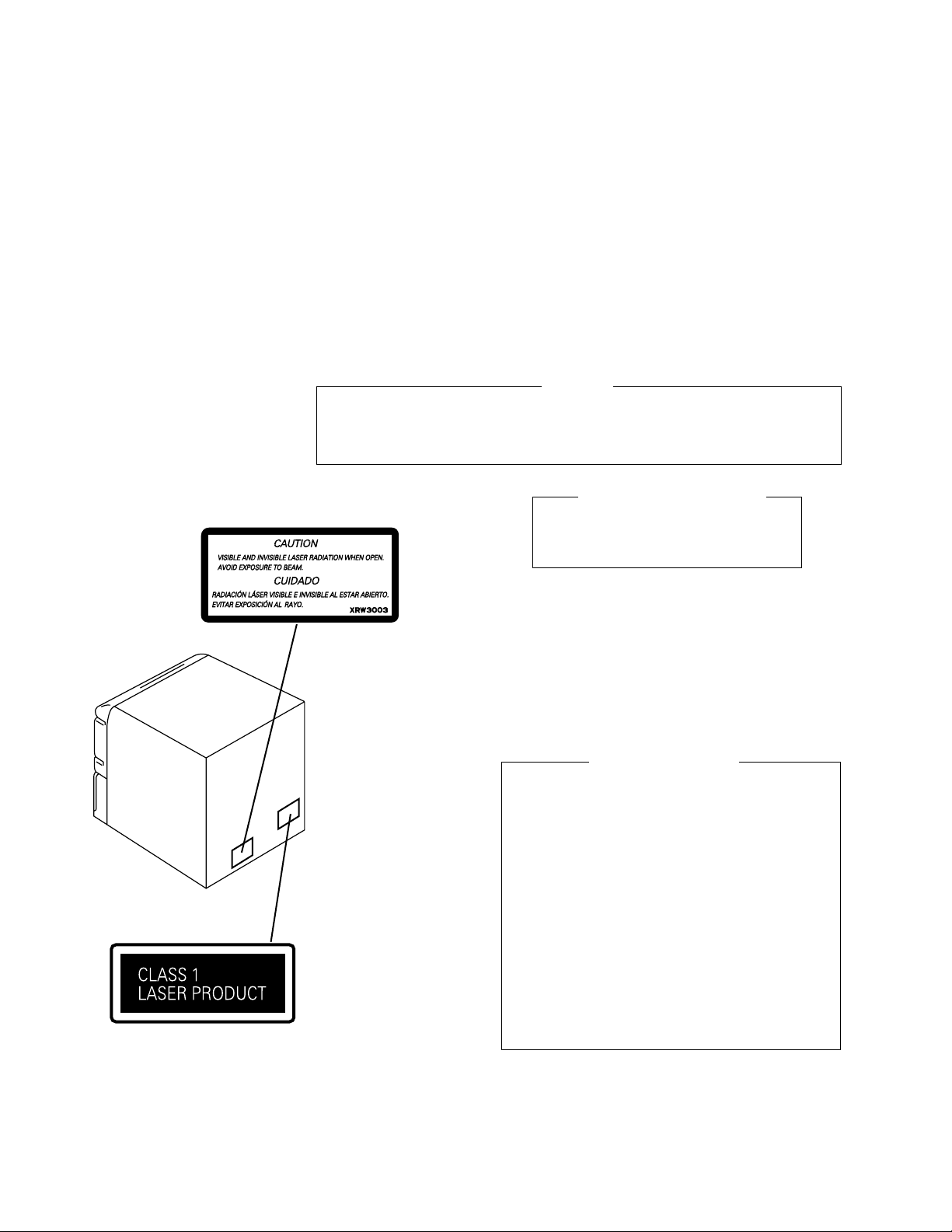
LABEL CHECK
Printed on the Rear Panel
THE AEL (ACCESSIBLE EMISSION LEVEL) OF THE LASER POWER OUTPUT IS LESS THAN CLASS 1
WARNING !
BUT THE LASER COMPONENT IS CAPABLE OF EMITTING RADIATION EXCEEDING THE LIMIT FOR
CLASS 1.
A SPECIALLY INSTRUCTED PERSON SHOULD DO SERVICING OPERATION OF THE APPARATUS.
LASER DIODE CHARACTERISTICS
FOR DVD : MAXIMUM OUTPUT POWER : 5 mW
WAVELENGTH : 655 nm
FOR CD : MAXIMUM OUTPUT POWER : 5mW
WAVELENGTH : 785 nm
Additional Laser Caution
1. Inside detection switch (S201 on the SMEB assy) and loadingstatus detection switch (S9503 on the MOT OR assy) are detected
by the microprocessor (IC11 in the DVDM assy).
• To per mit the laser diode to oscillate, it is required to set the
inside detection switch for the inside position (S201 : ON) and to
set the loading-status detection switch for the clamp position (the
center terminal of S9503 is shorted to +5V). The 655 nm laser
diode for DVD oscillation will continue if pin 19 of IC1 is shorted
to +5V (fault condition) in the DVDM assy.
The 785 nm laser diode for CD oscillates if pin 20 of IC1 is shorted
to +5V in the DVDM assy.
In the test mode ∗ , the laser diode oscillates when microprocessor detects a PLAY signal, or when the PLAY key is pressed
(S5931 ON in the DISPLAY assy), with the above requirements
satisfied.
2. When the cover is open, close vie wing through the objectiv e lens
with the naked eye will cause exposure to the laser beam.
∗ : Refer to page 82 on the ser vice manual RRV2329.
2
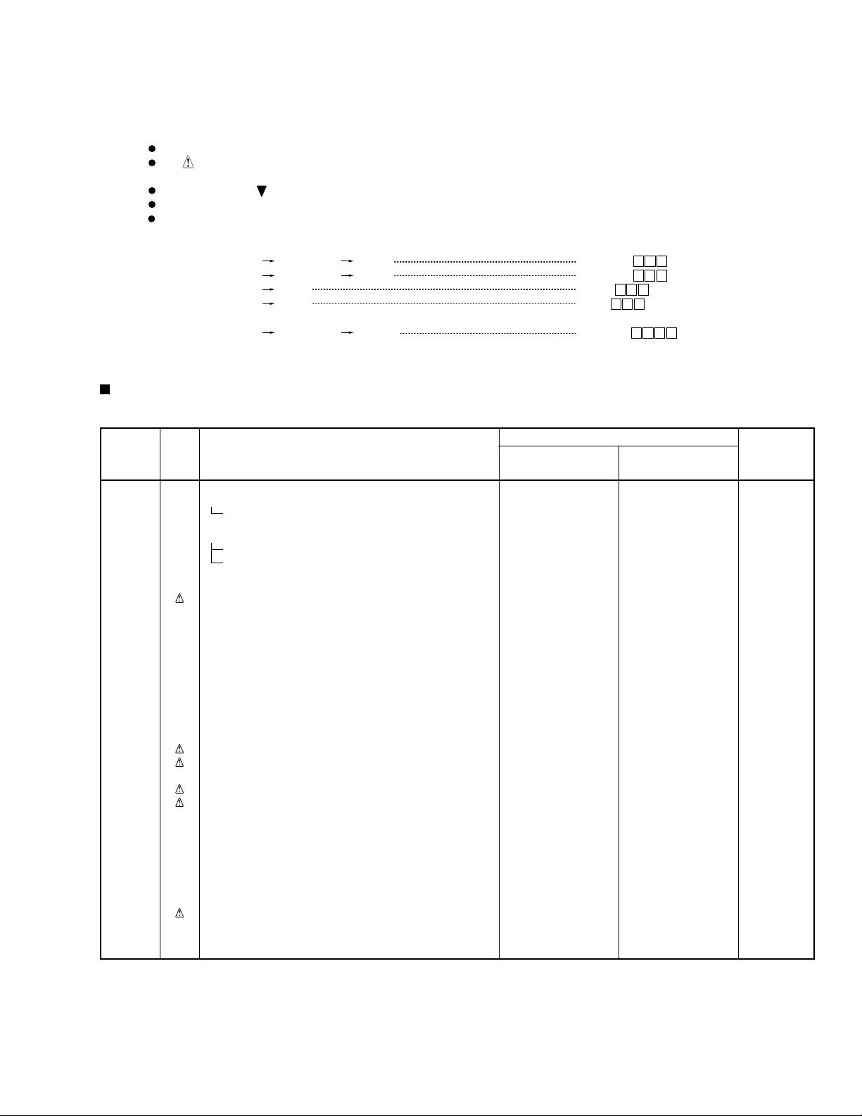
2. CONTRAST OF MISCELLANEOUS PARTS
XV-VS800, XV-VS600
NOTES:
Parts marked by "NSP" are generally unavailable because they are not in our Master Spare Parts List.
The mark found on some component parts indicates the importance of the safety factor of the part.
Therefore, when replacing, be sure to use parts of identical designation.
Screws adjacent to mark on product are used for disassembly.
Reference Nos. indicate the pages and Nos. in the service manual for the base model.
When ordering resistors, first convert resistance values into code form as shown in the following examples.
Ex.1 When there are 2 effective digits (any digit apart from 0), such as 560 ohm and 47k ohm (tolerance is shown by J=5%,
and K=10%).
560
47k
0.5
1
56 x 10
47 x 103
R50
1R0
1
561
473
RD1/4PU J
RD1/4PU J
RN2H K
RS1P K
561
473
R50
1R0
Ex.2 When there are 3 effective digits (such as in high precision metal film resistors).
5.62k RN1/4PC F562 x 10
CONTRAST TABLE for XV-VS800
1
5621
5621
XV-VS800/DXJN/NC and XR-A9800D/KUCXJ are constructed the same except for the following :
Part No.
Ref. No. Mark Symbol and Description XR-A9800D XV-VS800 Remarks
/KUCXJ /DXJN/NC
PCB ASSEMBLIES
P5- 1 AF ASSY XWZ3330 XWZ3322
P5- 4 PRIMARY ASSY XWZ3332 XWZ3326
P7- 1 DISPLAY ASSY XWZ3331 AWU7801
P3- 1 Power Cord ADG7022 ADG1154
P3- 5 Remote Control Unit XZN3109 XZN3110
P3- 9 Front Pad XHA3020 XHA3030
P3-10 Rear Pad XHA3021 XHA3031
P3-11 Packing Case XHD3144 XHD3282
P3-12 NSP Warranty Card ARY7045 Not used
P3-14 Operating Instructions (English/French) XRE3036 Not used
P5-12
P5-12
P5-13
P5-13
P5-25 Rear Panel XNC3065 XNC3132
P5-38 Tray Cap XAK3157 XAK3236
P5-41 NSP Fuse Card AAX2374 Not used
P5-42 NSP Getter XAX3175 XAX3271
P5-43 65 Label ARW7050 Not used
MAIN ASSY XWM3174 XWM3172
COMPLEX ASSY XWM3178 AWM7618
PACKING SECTION
Operating Instructions (Thai) Not used XRC3048
Caution Sheet XRH3004 Not used
EXTERIOR SECTION
Power Transformer (T1) (AC120V) XTS3042 Not used
Power Transformer (T1) Not used XTS3055
(AC110-127V/220-230V/240V)
Fuse (FU1 : 6.3A) REK1085 Not used
Fuse (FU1 : T5A) Not used AEK1061
Tray Panel DVD Not used XAK3251 For Tray Cap
Fuse (FU2, FU3 : T3.15A) Not used AEK1059 *1
NSP Name Label Not used XAL3102 *2
Caution Label Not used XRW3003 *3
Rear Sheet AED7037 Not used
3
XV-VS800, XV-VS600
Part No.
Ref. No. Mark Symbol and Description XR-A9800D XV-VS800 Remarks
/KUCXJ /DXJN/NC
P7-8 GND Plate C XNG3047 Not used
P7-8 GND Plate A Not used XNG3030
P7-18 Volume Knob XAA3013 XAA3022
P7-21 FUNC Button L XAD3061 XAD3118 No.8
P7-22 FUNC Button R XAD3051 XAD3112 No.10
P7-23 FUNC Frame L XAD3052 Not used
P7-24 FUNC Frame R XAD3053 Not used
P7-25 DVD ENT Button XAD3056 XAD3110 No.12
P7-26 Display Panel XAK3135 XAK3315
P7-27 EQ Panel XAK3150 Not used
P7-28 JOG Lens XAK3152 XAK3243 No.23
P7-29 V Lens XAK3153 XAK3313
P7-33 FL Cover XAK3164 XAK3239
P7-34 Cover Sheet L XAK3184 Not used
P7-35 Cover Sheet R XAK3185 Not used
P7-36 Power Button XAD3044 XAD3102 No.17
P7-37 CD Button XAD3045 XAD3104 No.19
P7-38 SC Button XAD3060 Not used
P7-39 SC Button L XAD3047 Not used
P7-40 SC Button R XAD3049 Not used
P7-41 DOLBY Button XAD3054 XAD3121 No.11
P7-42 Sub Panel XAK3203 XAK3271 No.6
P7-43 Standby Lens XAK3151 XAK3240 No.18
P7-44 Deck Lens L XAK3159 XAK3249 No.3
P7-45 Deck Lens R XAK3160 XAK3250 No.5
P7-46 JOG Conductor XAK3165 XAK3244 No.22
P7-47 Deck Door_L XAN3022 XAN3037 No.2
P7-48 Deck Door_R XAN3026 XAN3038 No.4
P7-49 Front Panel XMB3027 XMB3058 No.1
P7-50 DV Button L XAD3057 Not used
P7-51 DV Button R XAD3059 Not used
P7-52 NSP Front Panel ASSY XXG3066 XXG3117
Notes : For PCB ASSEMBLIES, Refer to “CONTRAST OF PCB ASSEMBLIES” and “3. SCHEMATIC DIAGRAM”.
The numbers in the remarks column correspond to the numbers on the “ FRONT PANEL ASSY ”.
*1 Refer to “3. SCHEMATIC DIAGRAM”.
*2 Stick Name Label on the Rear Panel.
*3 Refer to “LABEL CHECK”.
FRONT PANEL SECTION
FUNC Cap L Not used XAK3247 No.7
FUNC Cap R Not used XAK3248 No.9
SC Panel Not used XAK3268 No.26
SC Panel Assy Not used XXG3090 No.13
LED Barrier Not used XEC3022 No.24
SC Button L Not used XAD3105 No.29
SC Cap L Not used XAK3241 No.27
SC Button R Not used XAD3106 No.30
SC Cap R Not used XAK3267 No.28
ASES Button Not used XAD3114 No.20
Timer Button Not used XAD3115 No.21
Audio Button Not used XAD3107 No.14
Visual Button Not used XAD3108 No.15
O/C Button Not used XAD3103 No.16
Spacer XEB3012 Not used
Spacer XEB3013 Not used
Cushion Spacer XEB3015 Not used
Cushion Spacer XEB3016 Not used
Cushion Spacer XEB3017 Not used
Spacer XEC3014 Not used
Spacer XEC3019 Not used
4
XV-VS800, XV-VS600
CONTRAST TABLE for XV-VS600
XV -VS600/DXJN/NC and XR-A9800D/KUCXJ are constructed the same e xcept for the following :
Part No.
Ref. No. Mark Symbol and Description XR-A9800D XV-VS600 Remarks
/KUCXJ /DXJN/NC
PCB ASSEMBLIES
P5- 1 AF ASSY XWZ3330 AWU7789
P5- 2 SECONDARY ASSY XWZ3323 XWZ3317
P5- 3 REAR AMP ASSY XWZ3325 XWZ3319
P5- 4 PRIMARY ASSY XWZ3332 XWZ3320
P7- 1 DISPLAY ASSY XWZ3331 AWU7800
P3- 1
P3- 5 Remote Control Unit XZN3109 XZN3108
P3- 9 Front Pad XHA3020 XHA3030
P3-10 Rear Pad XHA3021 XHA3031
P3-11 Packing Case XHD3144 XHD3279
P3-12 NSP Warranty Card ARY7045 Not used
P3-14 Operating Instructions (English/French) XRE3036 Not used
P5-12
P5-12
P5-13
P5-13
P5-15 Power Bracket XNG3033 Not used
P5-25 Rear Panel XNC3065 XNC3129
P5-26 SEC Holder XMR3013 XMR3014
P5-38 Tray Cap XAK3157 XAK3236
P5-41 NSP Fuse Card AAX2374 Not used
P5-42 NSP Getter XAX3175 XAX3269
P5-43 65 Label ARW7050 Not used
P5-44 NSP $M Mecha. DVD (5ch) XXA3019 Not used
P5-44 NSP $M Mecha. DVD (2ch) Not used XXA3018
P7-8 GND Plate C XNG3047 Not used
P7-8 GND Plate A Not used XNG3030
P7-18 Volume Knob XAA3013 XAA3022
P7-21 FUNC Button L XAD3061 XAD3118 No.8
P7-22 FUNC Button R XAD3051 XAD3112 No.10
P7-23 FUNC Frame L XAD3052 Not used
P7-24 FUNC Frame R XAD3053 Not used
P7-25 DVD ENT Button XAD3056 XAD3110 No.12
P7-26 Display Panel XAK3135 XAK3314
P7-27 EQ Panel XAK3150 Not used
P7-28 JOG Lens XAK3152 XAK3243 No.23
MAIN ASSY XWM3174 AWM7605
COMPLEX ASSY XWM3178 AWM7617
PACKING SECTION
Power Cord ADG7022 ADG1154
Operating Instructions (Thai) Not used XRC3048
Caution Sheet XRH3004 Not used
EXTERIOR SECTION
Power Transformer (T1) (AC120V) XTS3042 Not used
Power Transformer (T1) Not used XTS3039
(AC110-127V/220-230V/240V)
Fuse (FU1 : 6.3A) REK1085 Not used
Fuse (FU1 : T5A) Not used AEK1061
Tray Panel DVD Not used XAK3251
Fuse (FU2, FU3 : T3.15A) Not used AEK1059 *1
NSP Name Label Not used XAL3100 *2
Caution Label Not used XRW3003 *3
Rear Sheet AED7037 Not used
FRONT PANEL SECTION
FUNC Cap L Not used XAK3247 No.7
FUNC Cap R Not used XAK3248 No.9
SC Panel Not used XAK3268 No.26
SC Panel Assy Not used XXG3090 No.13
5
XV-VS800, XV-VS600
Part No.
Ref. No. Mark Symbol and Description XR-A9800D XV-VS600 Remarks
/KUCXJ /DXJN/NC
P7-29 V Lens XAK3153 XAK3313
P7-33 FL Cover XAK3164 XAK3239
P7-34 Cover Sheet L XAK3184 Not used
P7-35 Cover Sheet R XAK3185 Not used
P7-36 Power Button XAD3044 XAD3102 No.17
P7-37 CD Button XAD3045 XAD3104 No.19
P7-38 SC Button XAD3060 Not used
P7-39 SC Button L XAD3047 Not used
P7-40 SC Button R XAD3049 Not used
P7-41 DOLBY Button XAD3054 XAD3121 No.11
P7-42 Sub Panel XAK3203 XAK3246 No.6
P7-43 Standby Lens XAK3151 XAK3240 No.18
P7-44 Deck Lens L XAK3159 XAK3249 No.3
P7-45 Deck Lens R XAK3160 XAK3250 No.5
P7-46 JOG Conductor XAK3165 XAK3244 No.22
P7-47 Deck Door_L XAN3022 XAN3037 No.2
P7-48 Deck Door_R XAN3026 XAN3038 No.4
P7-49 Front Panel XMB3027 XMB3058 No.1
P7-50 DV Button L XAD3057 Not used
P7-51 DV Button R XAD3059 Not used
P7-52 NSP Front Panel ASSY XXG3066 XXG3113
Notes : For PCB ASSEMBLIES, Refer to “CONTRAST OF PCB ASSEMBLIES” and “3. SCHEMATIC DIAGRAM”.
The numbers in the remarks column correspond to the numbers on the “ FRONT PANEL ASSY ”.
*1 Refer to “3. SCHEMATIC DIAGRAM”. *2 Stick Name Label on the Rear Panel. *3 Refer to “LABEL CHECK”.
LED Barrier Not used XEC3022 No.24
SC Button L Not used XAD3105 No.29
SC Cap L Not used XAK3241 No.27
SC Button R Not used XAD3106 No.30
SC Cap R Not used XAK3267 No.28
ASES Button Not used XAD3114 No.20
Timer Button Not used XAD3115 No.21
Audio Button Not used XAD3107 No.14
Visual Button Not used XAD3108 No.15
O/C Button Not used XAD3103 No.16
Spacer XEB3012 Not used
Spacer XEB3013 Not used
Cushion Spacer XEB3015 Not used
Cushion Spacer XEB3016 Not used
Cushion Spacer XEB3017 Not used
Spacer XEC3014 Not used
Spacer XEC3019 Not used
CONTRAST OF $M MECHA. DVD
XXA3018 and XXA3019 are constructed the same except for the following :
Part No.
Ref. No. Mark Symbol and Description XXA3019 XXA3018 Remarks
(XR-A9800D) (XV-VS600)
P5-10 CONNECT ASSY (6CH) XWX3023 Not used
P5-10 CONNECT ASSY (2CH) Not used XWX3019
P5-14 25P Flexible Cable XDD3046 Not used
P5-14 15P Flexible Cable Not used XDD3049
P5-18 30P Flexible Cable XDD3044 Not used
P5-18 16P Flexible Cable Not used XDD3043
P5-21 7P Flexible Cable/30V XDD3053 ADD7197
P5-23 DVD Base XNG3034 ANG7262
P5-24 DVD Shield XNK3006 ANK7097
P5-55 21P Flexible Cable XDD3052 Not used
P5-55 7P Flexible Cable Not used XDD3045
Notes : For PCB ASSEMBLIES, Refer to “PCB PARTS LIST”, “3. SCHEMATIC DIAGRAM” and “4. PCB CONNECTION DIAGRAM”.
6
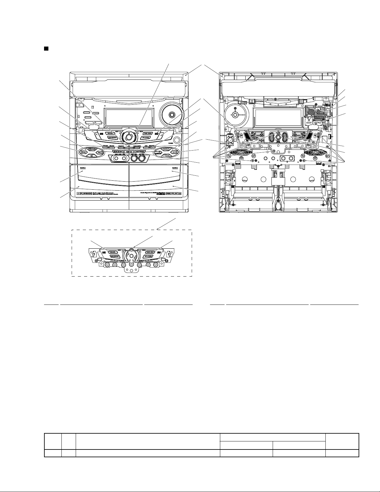
FRONT PANEL ASSY
XV-VS800, XV-VS600
12
14
20
23
7
8
3
2
13
27, 29
26
28, 30
13
15
21
9
10
11
5
4
1
18
17
19
16
6
24
25
22
25
(1) FRONT PANEL ASSY PARTS LIST
Mark No. Description Part No. Mark No. Description Part No.
1 Front Panel XMB3058
2 Deck Door_L XAN3037
3 Deck Lens L XAK3249
4 Deck Door_R XAN3038
5 Deck Lens R XAK3250
6 Sub Panel See Contrast table (2)
7 FUNC Cap L XAK3247
8 FUNC Button L XAD3118
9 FUNC Cap R XAK3248
10 FUNC Button R XAD3112
11 DOLBY Button XAD3121
12 CD ENT Button XAD3110
13 SC Panel Assy XXG3090
14 Audio Button XAD3107
15 Visual Button XAD3108
16 O/C Button XAD3103
17 Power Button XAD3102
18 Standby Lens XAK3240
19 CD Button XAD3104
20 ASES Button XAD3114
21 Timer Button XAD3115
22 JOG Conductor XAK3244
23 JOG Lens XAK3243
24 LED Barrier XEC3022
25 Screw BPZ30P080FMC
26 SC Panel XAK3268
27 SC Cap L XAK3241
28 SC Cap R XAK3267
29 SC Button L XAD3105
30 SC Button R XAD3106
(2) CONTRAST TABLE
XV-VS600 and XV-VS800 are constructed the same except for the following :
Mark No. Symbol and Description
6 Sub Panel XAK3271 XAK3246
XV-VS800 XV-VS600
Part No.
Remarks
7
 Loading...