

Pioneer XV-DV820, XV-DV620 Service Manual
7
Q
Q
TEL 13942296513 QQ 376315150 892498299
3
DVD / CD RECEIVER
6
3
1
5
1
5
0
XV-DV820
XV-DV620
THIS MANUAL IS APPLICABLE TO THE FOLLOWING MODEL(S) AND TYPE(S).
Type
TEL
13942296513
KUCXJN AC120V 1
XV-DV820 XV-DV620
Model
Power Requirement Region No. Remarks
7
3
Q
Q
6
8
OPEN/CLOSE
3
9
1
5
4
2
DVD/CD FM/AM DOWN VOLUME UP STANDBY/ON
—
TUNER
67¶0
+
0
5
1
9
PHONES
8
9
8
2
4
2
9
8
9
9
ORDER NO.
RRV2683
9
9
2
TEL 13942296513 QQ 376315150 892498299
For details, refer to "Important symbols for good services" on the next page.
w
w
w
PIONEER CORPORATION 4-1, Meguro 1-chome, Meguro-ku, Tokyo 153-8654, Japan
PIONEER ELECTRONICS (USA) INC. P.O. Box 1760, Long Beach, CA 90801-1760, U.S.A.
PIONEER EUROPE NV Haven 1087, Keetberglaan 1, 9120 Melsele, Belgium
PIONEER ELECTRONICS ASIACENTRE PTE. LTD. 253 Alexandra Road, #04-01, Singapore 159936
PIONEER CORPORATION 2002
.
xia
o
y
u
1
6
3
.
c
o
m
T – ZZV SEPT. 2002 Printed in Japan
1
23
4
SAFETY INFORMATION
A
7
This service manual is intended for qualified service technicians; it is not meant for the casual
Q
Q
do-it-yourselfer. Qualified technicians have the necessary test equipment and tools, and have been
trained to properly and safely repair complex products such as those covered by this manual.
Improperly performed repairs can adversely affect the safety and reliability of the product and may
void the warranty . If you are not qualified to perform the repair of this product properly and safely, you
should not risk trying to do so and refer the repair to a qualified service technician.
WARNING
This product contains lead in solder and certain electrical parts contain chemicals which are known to the state of California to
B
cause cancer, birth defects or other reproductive harm.
Health & Safety Code Section 25249.6 – Proposition 65
TEL 13942296513 QQ 376315150 892498299
NOTICE
(FOR CANADIAN MODEL ONLY)
Fuse symbols (fast operating fuse) and/or (slow operating fuse) on PCB indicate that replacement
parts must be of identical designation.
REMARQUE
(POUR MODÈLE CANADIEN SEULEMENT)
Les symboles de fusible (fusible de type rapide) et/ou (fusible de type lent) sur CCI indiquent que
C
les pièces de remplacement doivent avoir la même désignation.
3
6
3
1
5
1
5
0
8
9
2
4
9
8
2
9
9
TEL 13942296513 QQ 376315150 892498299
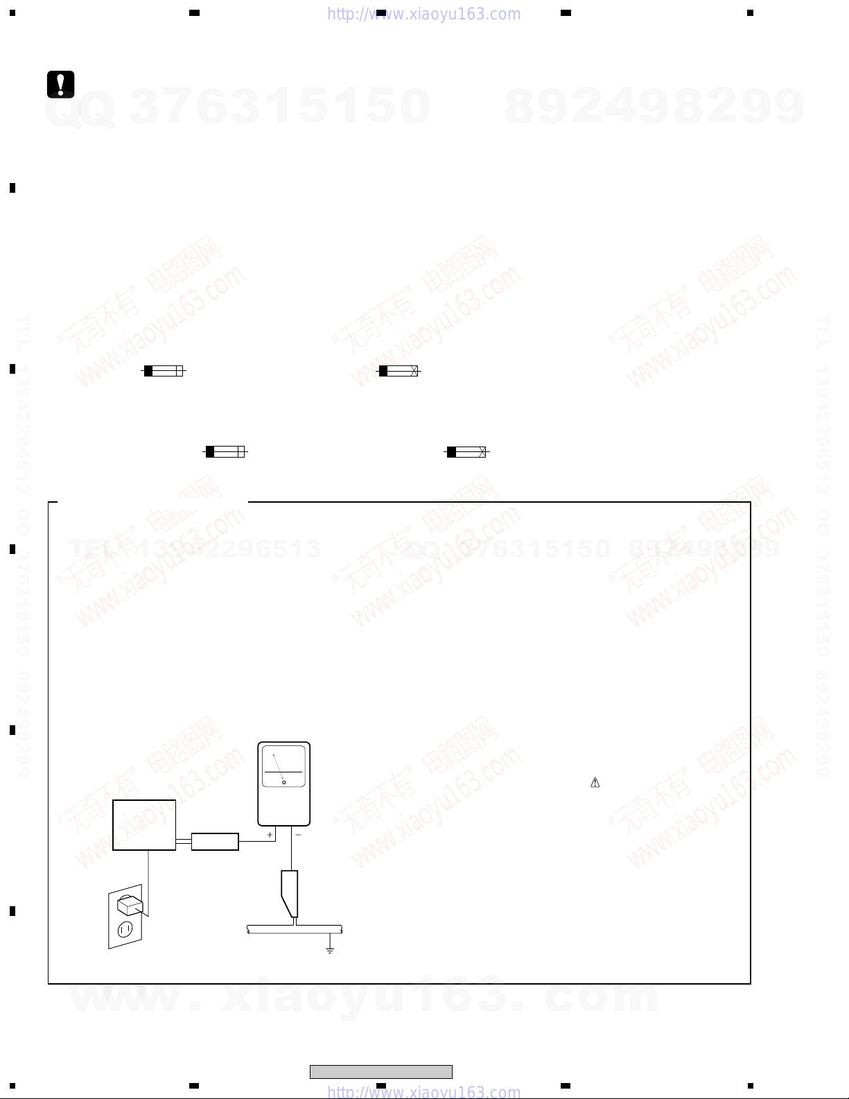
(FOR USA MODEL ONLY)
1. SAFETY PRECAUTIONS
The following check should be performed for the
continued protection of the customer and service
TEL
technician.
LEAKAGE CURRENT CHECK
Measure leakage current to a known earth ground
(water pipe, conduit, etc.) by connecting a leakage
D
E
current tester such as Simpson Model 229-2 or
equivalent between the earth ground and all exposed
metal parts of the appliance (input/output terminals,
screwheads, metal overlays, control shaft, etc.). Plug
the AC line cord of the appliance directly into a 120V
AC 60 Hz outlet and turn the AC power switch on. Any
current measured must not exceed 0.5 mA.
13942296513
Leakage
current
Device
under
test
Also test with
plug reversed
(Using AC adapter
plug as required)
Test all
exposed metal
surfaces
AC Leakage Test
tester
Reading should
not be above
0.5 mA
Earth
ground
ANY MEASUREMENTS NOT WITHIN THE
LIMITS OUTLINED ABOVE ARE INDICATIVE
Q
Q
OF A POTENTIAL SHOCK HAZARD AND
MUST BE CORRECTED BEFORE RETURNING THE APPLIANCE TO THE CUSTOMER.
2. PRODUCT SAFETY NOTICE
have special safety related characteristics. These are
often not evident from visual inspection nor the
protection afforded by them necessarily can be obtained
by using replacement components rated for voltage,
wattage, etc. Replacement parts which have these
special safety characteristics are identified in this
Service Manual.
identified by marking with a
on the parts list in this Service Manual.
The use of a substitute replacement component which
does not have the same safety characteristics as the
PIONEER recommended replacement one, shown in the
parts list in this Service Manual, may create shock, fire,
or other hazards.
instructions are issued from time to time. For the latest
information, always consult the current PIONEER
Service Manual. A subscription to, or additional copies
of, PIONEER Service Manual may be obtained at a
nominal charge from PIONEER.
7
3
Many electrical and mechanical parts in the appliance
Electrical components having such features are
Product Safety is continuously under review and new
6
3
1
5
1
5
8
0
on the schematics and
9
2
4
9
8
2
9
9
F
2
w
w
w
1234
.
xia
o
y
u
1
6
XV-DV820, XV-DV620
3
.
c
o
m
Q
1
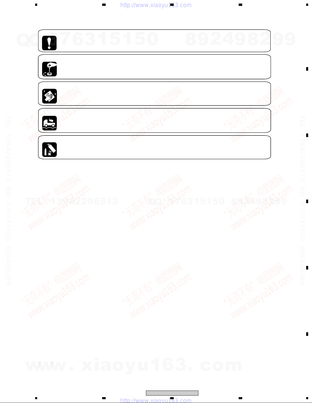
[ Important symbols for good services ]
In this manual, the symbols shown-below indicate that adjustments, settings or cleaning should be made securely.
When you find the procedures bearing any of the symbols, be sure to fulfill them:
1. Product safety
You should conform to the regulations governing the product (safety, radio and noise, and other regulations), and
Q
7
3
should keep the safety during servicing by following the safety instructions described in this manual.
2. Adjustments
To keep the original performances of the product, optimum adjustments or specification confirmation is indispensable.
In accordance with the procedures or instructions described in this manual, adjustments should be performed.
3. Cleaning
For optical pickups, tape-deck heads, lenses and mirrors used in projection monitors, and other parts requiring cleaning,
proper cleaning should be performed to restore their performances.
6
3
1
5
1
234
5
0
8
9
2
4
9
8
2
9
A
9
B
TEL 13942296513 QQ 376315150 892498299
TEL
4. Shipping mode and shipping screws
To protect the product from damages or failures that may be caused during transit, the shipping mode should be set or
the shipping screws should be installed before shipping out in accordance with this manual, if necessary.
5. Lubricants, glues, and replacement parts
Appropriately applying grease or glue can maintain the product performances. But improper lubrication or applying
glue may lead to failures or troubles in the product. By following the instructions in this manual, be sure to apply the
prescribed grease or glue to proper portions by the appropriate amount.For replacement parts or tools, the prescribed
ones should be used.
13942296513
Q
Q
3
7
6
3
1
5
1
5
0
8
9
2
4
9
8
2
9
TEL 13942296513 QQ 376315150 892498299
C
9
D
w
w
w
.
xia
1
o
y
u
1
6
XV-DV820, XV-DV620
2
3
.
c
3
o
m
E
F
3
4
1
CONTENTS
SAFETY INFORMATION ......................................................................................................................................2
A
B
TEL 13942296513 QQ 376315150 892498299
C
D
E
1. SPECIFICATIONS ............................................................................................................................................5
2. EXPLODED VIEWS AND PARTS LIST .......................................................................................................... 6
Q
Q
2.1 PACKING....................................................................................................................................................6
2.2 EXTERIOR SECTION ............................................................................................................................... 8
2.3 FRONT SECTION ................................................................................................................................... 10
2.4 LOADING MECANISM ASSY ................................................................................................................. 12
2.5 TRAVERSE MECHANISM ASSY ........................................................................................................... 14
3. BLOCK DIAGRAM AND SCHEMATIC DIAGRAM ........................................................................................ 16
3.1 BLOCK DIAGRAM................................................................................................................................... 16
3.2 LOAB ASSY and OVERALL WIRING DIAGRAM................................................................................... 18
3.3 DVDM ASSY 1/2 ..................................................................................................................................... 20
3.4 DVDM ASSY 2/2 ..................................................................................................................................... 22
3.5 DVD IF ASSY .......................................................................................................................................... 24
3.6 DSP ASSY............................................................................................................................................... 26
3.7 FM/AM TUNER MODULE ....................................................................................................................... 28
3.8 AMP ASSY .............................................................................................................................................. 30
3.9 CONTROL ASSY 1/3, TRADE2 and TRADE3 ASSYS .......................................................................... 32
3.10 CONTROL ASSY 2/3 for XV-DV820..................................................................................................... 34
3.11 CONTROL ASSY 2/3 for XV-DV620..................................................................................................... 36
3.12 CONTROL ASSY 3/3 ............................................................................................................................ 38
3.13 POWER ASSY 1/2 ................................................................................................................................ 40
3.14 POWER ASSY 2/2 and TRADE1 ASSY ............................................................................................... 42
3.15 DISPLAY and HP ASSYS ..................................................................................................................... 44
3.16 WAVEFORMS ....................................................................................................................................... 46
4. PCB CONNECTION DIAGRAM..................................................................................................................... 47
TEL
4.1 LOAB ASSY ............................................................................................................................................ 47
4.2 DVDM ASSY ........................................................................................................................................... 48
4.3 DVD IF ASSY .......................................................................................................................................... 52
4.4 DSP ASSY............................................................................................................................................... 54
4.5 FM/AM TUNER MODULE ....................................................................................................................... 56
4.6 DISPLAY and HP ASSYS ....................................................................................................................... 57
4.7 AMP ASSY .............................................................................................................................................. 58
4.8 CONTROL, TRADE2 and TRADE3 ASSYS ........................................................................................... 60
4.9 POWER and TRADE1 ASSYS ............................................................................................................... 64
5. PCB PARTS LIST .......................................................................................................................................... 68
6. ADJUSTMENT ............................................................................................................................................... 75
7. GENERAL INFORMATION............................................................................................................................ 81
7.1 DIAGNOSIS............................................................................................................................................. 81
7.1.1 TEST MODE .................................................................................................................................... 81
7.1.2 DISPLAY OF THE MECHANISM ERROR HISTORY..................................................................... 87
7.1.3 TROUBLE SHOOTING.................................................................................................................... 90
7.1.4 SEQUENCE AFTER POWER ON...................................................................................................92
7.1.5 PROTECTION CIRCUIT.................................................................................................................. 95
7.1.6 DISASSEMBLY................................................................................................................................ 97
7.2 IC ........................................................................................................................................................... 102
7.3 CLEANING ............................................................................................................................................ 121
8. PANEL FACILITIES ..................................................................................................................................... 122
7
3
13942296513
6
3
23
1
5
1
5
0
Q
Q
3
7
6
8
3
9
1
5
1
2
5
4
0
9
8
9
4
8
2
4
2
9
8
9
2
9
9
TEL 13942296513 QQ 376315150 892498299
9
F
4
w
w
w
1234
.
xia
o
y
u
1
6
XV-DV820, XV-DV620
3
.
c
o
m
1
234
1. SPECIFICATIONS
Amplifier section
Continuous Power Output (RMS):
Front, center, surround... 75 W per channel
7
Q
Q
TEL 13942296513 QQ 376315150 892498299
TEL
3
Subwoofer75 W (100 Hz, 10 % T.H.D., 6 Ω)
Continuous Power Output :
Front, center, surround... 62 W per channel
Subwoofer .62 W (100 Hz, 1 % T.H.D., 6 Ω)
Disc section
Digital audio
characteristics ............. DVD fs: 96 kHz, 24-bit
Type ........ DVD system, video CD system and
Frequency response ............... 4 Hz to 44 kHz
FM tuner section
Frequency range.................... 87.5 – 108 MHz
Antenna............................... 75 Ω, unbalanced
AM tuner section
Frequency range
With 10 kHz step...... 530 kHz to 1,700 kHz
Antenna..................................... Loop antenna
Miscellaneous
Power requirements
Power consumption
Power consumption in standby
Dimensions ... 360 (W) x 70 (H) x 393 (D) mm/
Weight ................................... 7.0 kg/15 lb 7 oz
13942296513
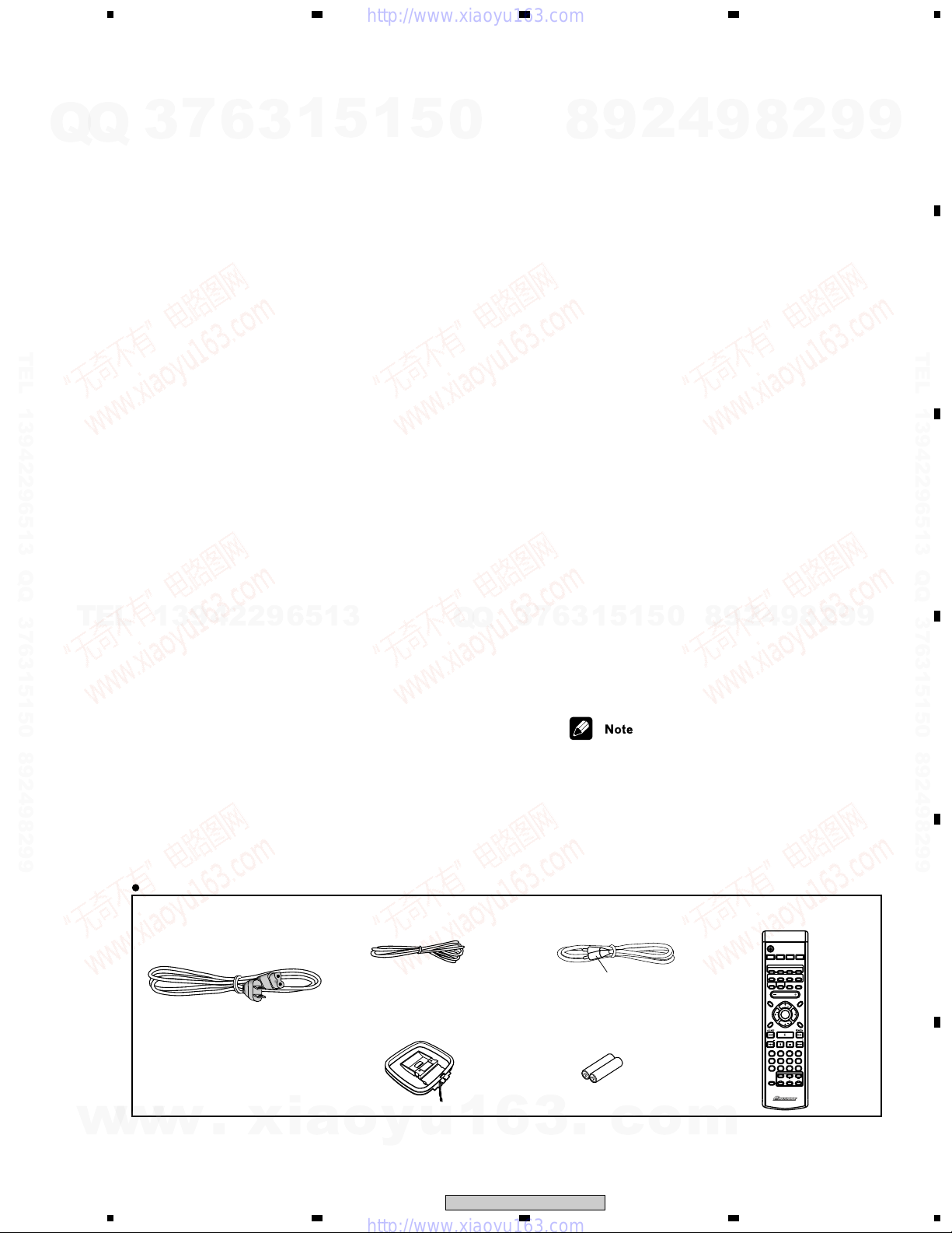
Accessories (DVD/CD receiver)
Remote control............................................. 1
AA/R6P dry cell batteries .............................. 2
Video cable (yellow plugs) ............................ 1
AM loop antenna........................................... 1
FM antenna .................................................. 1
Power cord .................................................... 1
Warranty Card............................................... 1
Operating instructions
Quick setup guide
6
compact disc digital audio system
U.S. model AC 120V, 60Hz
U.S. model...............................
U.S. model..............................0.38 W
3
14-
/16 (W) x 2-3/4 (H) x 15-1/2 (D) in.
1
5
3
(1 kHz, 10 % T.H.D., 6 Ω)
(1 kHz, 1 % T.H.D., 6 Ω)
...............
1
215 W
5
0
Q
Q
3
7
Speaker System
Front and surround speakers
Enclosure ..............Closed-box bookshelf type
9
8
System .......................... 8.7 cm 1-way system
Speakers ..............................8.7 cm cone type
Nominal impedance .................................. 6 Ω
Frequency range ................. 100 Hz to 20 kHz
Maximum Input Power ............................75 W
Dimensions ... 110 (W) x 155 (H) x 76 (D) mm/
Weight ................................. 0.75 kg/1 lb 10 oz
Center speaker
Enclosure ..............Closed-box bookshelf type
System .......................... 8.7 cm 1-way system
Speakers ..............................8.7 cm cone type
Nominal impedance .................................. 6 Ω
Frequency range ................. 100 Hz to 20 kHz
Maximum Input Power ............................75 W
Dimensions ... 200 (W) x 110 (H) x 76 (D) mm/
Weight ................................... 0.8 kg/1 lb 12 oz
Subwoofer
Enclosure ...................... Bass-reflex floor type
System ........................... 16 cm 1-way system
Speaker.................................16 cm cone type
Nominal impedance .................................. 6 Ω
Frequency range .................. 30 Hz to 2.8 kHz
Maximum Input Power ............................75 W
Dimensions . 130 (W) x 360 (H) x 360 (D) mm/
3
6
Weight ................................... 4.0 kg/8 lb 13 oz
Accessories (Speaker system)
Speaker cords ............................................... 6
Non-slip pads .............................................. 24
• Specifications and design subject to
1
5-
/8 (W) x 14-3/16 (H) x 14-3/16 (D) in.
1
5
1
possible modification without notice,
due to improvements.
4
2
(magnetically shielded)
5
4-
/16 (W) x 6-1/8 (H) x 3 (D) in.
(magnetically shielded)
7
7-
/8 (W) x 4-5/16 (H) x 3 (D) in.
(magnetically shielded)
8
0
5
9
9
8
2
4
9
2
8
9
2
9
A
9
B
TEL 13942296513 QQ 376315150 892498299
C
9
D
w
w
Accessories
• Power cord
(XDG3007)
w
.
1
xia
• FM Antenna
(ADH7028)
• AM Loop Antenna
(ATB7009)
o
y
u
1
6
XV-DV820, XV-DV620
2
• Video Cord
(L = 1.5m)(VDE1053)
Yellow
• Dry Cell Battery
(R6P, AA)
3
.
c
3
o
• Remote Control Unit
(AXD7337)
m
STANDBY/ON
TV LINE
FM/AMDVD/CD
DVD
AUDIO SUBTITLEANGLE
AUTO
SURROUND ADVANCED
ROOM
BASS MODESYSTEM DISP
SETUP
VOLUME
SYSTEM SETUP
TUNE
DVD SETUP
ENTER
SOUND
MODE
TUNE
FOLDER FOLDER
PROGRAM
REPEAT RANDOM
21
3
TEST TONE
CH LEVEL TIMER
546
DIMMER
DVD DISP
8790
TV CONTROL
SHIFT
CHANEL
INPUT
5.1ch DVD
SURROUND SYSTEM
E
L1/L2
ZOOM
QUIET/
MIDNIGHT
MUTE
TOP MENU
DVD MENU
STST
RETURN
CLEAR
ENTER
VOLUME
AXD7337
F
5
4
1
2. EXPLODED VIEWS AND PARTS LIST
23
4
NOTES:
A
Q
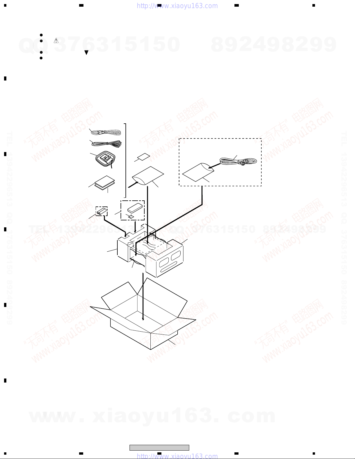
2.1 PACKING
B
TEL 13942296513 QQ 376315150 892498299
C
Parts marked by "NSP" are generally unavailable because they are not in our Master Spare Parts List.
The mark found on some component parts indicates the importance of the safety factor of the part.
Therefore, when replacing, be sure to use parts of identical designation.
Q
Screws adjacent to mark on product are used for disassembly.
For the applying amount of lubricants or glue, follow the instructions in this manual.
(In the case of no amount instructions, apply as you think it appropriate.)
3
7
6
4
2
3
11
(XV-DV820
Only)
3
8,9,10
1
5
12
1
5
17
0
8
17
9
2
1
4
9
8
2
9
9
TEL 13942296513 QQ 376315150 892498299
6
5
7
TEL
D
E
13942296513
14
16
Q
Q
15
13
3
7
6
3
1
5
1
5
0
8
9
2
4
9
8
2
9
9
F
6
w
w
w
1234
.
xia
o
y
u
1
6
XV-DV820, XV-DV620
3
.
c
o
m
1
(1) PACKING PARTS LIST
Mark No. Description Part No.
Q
TEL 13942296513 QQ 376315150 892498299
> 1 AC Power Code XDG3007
Q
NSP 7 Dry Cell Batteries(R6P,AA) VEM1031
NSP 12 Warranty Card ARY7045
7
3
2 FM Wire Antenna ADH7028
3 AM Loop Antenaa ATB7009
4 Video Code(L=1.5m) VDE1053
5 Remote Control AXD7337
6 Battery Cover AZA7424
8 Operating Instructions(English) See Contrast table (2)
9 Operating Instructions Basic See Contrast table (2)
10 Operating Instructions(French) See Contrast table (2)
11 SP Assy Instruction Manual See Contrast table (2)
13 Pad F AHA7387
14 Pad R AHA7388
15 Packing Case See Contrast table (2)
6
(English, French)
(English,French)
3
1
5
1
234
5
0
8
9
2
4
9
8
2
9
A
9
B
TEL 13942296513 QQ 376315150 892498299
16 Packing Sheet AHG7102
NSP 17 Polyethylene Bag Z21-038
TEL
13942296513
(2) CONTRAST TABLE
XV-DV820/KUCXJN and XV-DV620/KUCXJN are constructed the same except for the following:
Mark
No.
8 Operating Instructions (English) ARB7274 ARB7272
9 Operating Instructions Basic ARE7316 ARE7312
10 Operating Instructions (French) ARC7443 ARC7439
11 SP Assy Instruction Manual ARE7322 Not used
15 Packing Case AHD8121 AHD8100
Symbol and Description
XV-DV820/KUCXJN XV-DV620/KUCXJN
(English, French)
(English, French)
Q
Q
7
3
Part No.
6
3
1
5
1
5
0
8
9
4
2
Remarks
9
8
2
9
C
9
D
E
w
w
w
.
xia
1
o
y
u
1
6
XV-DV820, XV-DV620
2
3
.
c
3
o
m
F
7
4
1
23
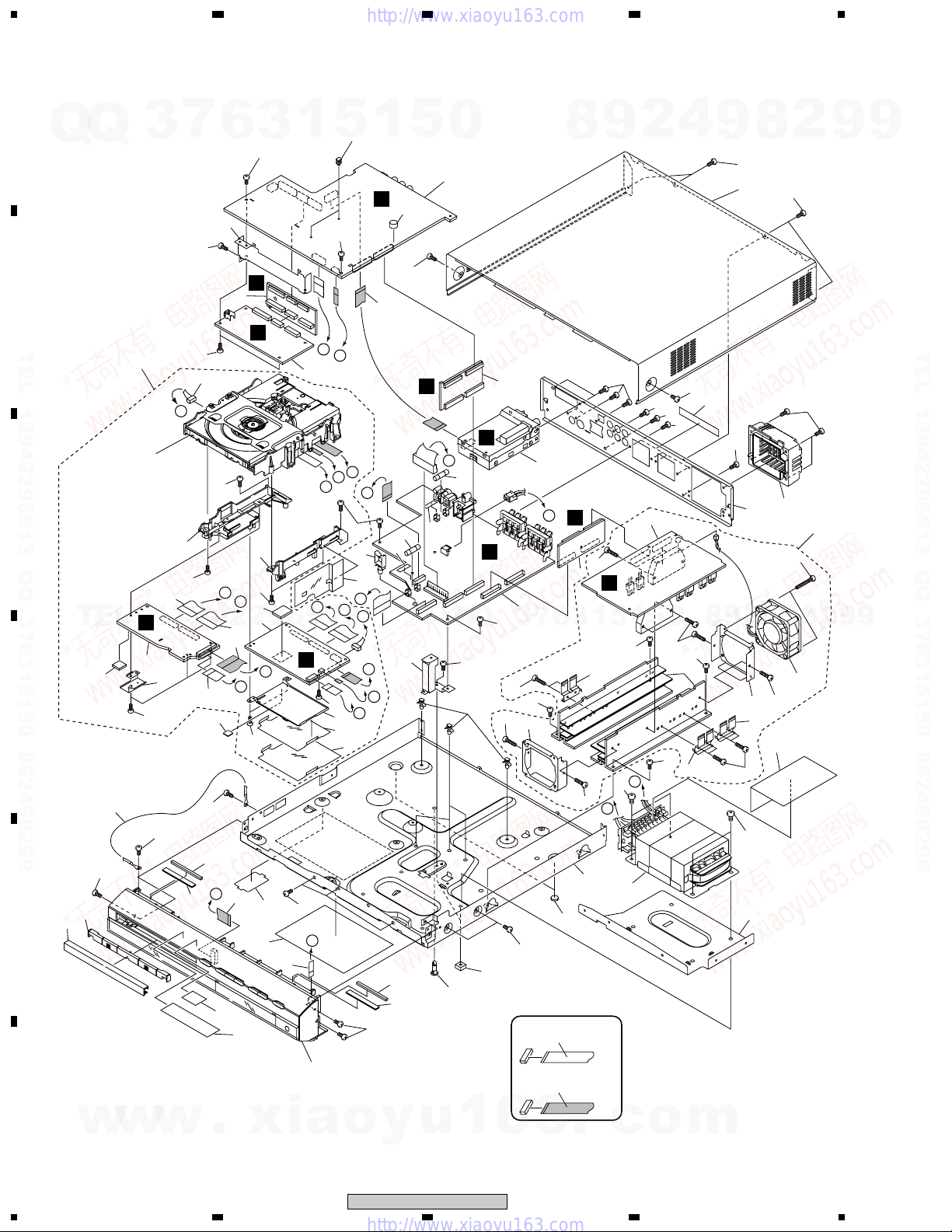
2.2 EXTERIOR SECTION
A
7
58
3
71
12
53
13942296513
C
2
56
64
21
Q
Q
B
TEL 13942296513 QQ 376315150 892498299
Refer to
"2.4 LOADING
MECHANISM ASSY".
C
Note :
No.53 and No.54 FFCs are
attached as they are
sandwiched between
No.60 and No.61.
TEL
D
E
62
64
65
65
55
20
65
6
25
65
C
38
8
D
54
19
A
64
3
65
I
D
63
64
59
1
B
1
3
C
B
5
65
I
G
F
64
57
60
1
5
29
73
0
6
14
65
37
E
Q
7
J
3
65
51
51
H
K
69
Q
30
G
18
J
H
A
65
14
69
31
34
B
D
E
24
H
G
F
61
4
4
2
9
8
67
67
73
4
L
L
51
10
9
7
65
49
6
3
1
48
51
F
K
5
66
65
1
L
5
5
0
51
65
67
50
48
73
65
9
43
8
73
9
73
42
2
51
8
23
4
49
48
51
35
73
40
52
9
2
65
72
8
47
9
2
9
9
TEL 13942296513 QQ 376315150 892498299
9
74
36
68
I
.
17
70
44
65
33
45
J
16
Refer to
"2.3 FRONT PANEL".
xia
65
68
36
65
o
y
u
XV-DV820, XV-DV620
32
1
28
NON-CONTACT
SIDE
CONTACT SIDE
6
3
27
.
22
13
c
o
m
65
E
F
41
8
39
w
w
w
1234
66
26
1
(1) EXTERIOR SECTION PARTS LIST
234
Mark No. Description Part No. Mark No. Description Part No.
1 DVDM ASSY AWM7750
7
Q
Q
TEL 13942296513 QQ 376315150 892498299
TEL
3
2 DVD IF ASSY AWM7677
3 DSP ASSY AWX8059
4 FM/AM TUNER MODULE AXQ7228
5 AMP ASSY AWM7720
6 CONTROL ASSY See Contrast table (2)
7 TRADE2 ASSY AWU8043
8 TRADE3 ASSY AWU8044
9 POWER ASSY AWU8032
10 TRADE1 ASSY AWU8036
11 • • • • • •
NSP 12 Loading Mechanism Assy VWT1188
> 13 Power Transformer (T1) ATS7334
> 14 Fuse (FU1,FU2 : 6.3A 125V) REK1069
15 • • • • • •
16 5P FFC/30V ADD7378
17 13P FFC/60V ADD7379
18 13P FFC/30V ADD7380
19 30P FFC/30V ADD7381
20 16P FFC/30V ADD7382
NSP 21 Earth Lead DE005VF0
NSP 22 Chassis ANA7145
23 Rear Panel See Contrast table (2)
24 Angle DCS2 ANG7423
25 Angle DSP ANG7424
13942296513
26 Trans Frame ANG7427
27 Leg AEB7090
28 S Cover (Rub) AEB7262
29 C Spacer (Rub) AEB7276
NSP 30 PCB Spacer AEC7156
31 Wire Saddle AEC7297
32 Locking Card Spacer AEC7372
33 Bottom Plate AEC7420
34 Barrier S AEC7429
35 Barrier AEC7453
6
3
1
5
1
5
0
Q
Q
NSP 50 Heat Sink ANH7161
7
3
NSP 69 Fuse Card AAX2374
NSP 70 Energy Star Label AAX7876
36 Spacer AEC7454
9
8
37 Card Spacer DEC1772
38 Sapcer XEC3006
39 Tray Mold AAK8013
40 FAN Cover AMR7440
41 AL Tray Panel AAK8014
42 Bonnet AZN7910
43 Terminal Sheet AAK8040
44 Getter Label DCS2 See Contrast table (2)
45 Name Sheet See Contrast table (2)
46 • • • • • •
47 DC FAN Motor AXM7025
48 FET Bracket A ANG7418
49 FAN Plate ANG7425
51 Screw BBZ30P140FMC
52 Screw BBZ30P300FZK
53 26P FFC/60V ADD7372
54 30P FFC/60V ADD7373
55 Connector Assy PG05KK-E25
56 Heat Plate ANG7426
57 Shield Case ANK7108
58 Radiation Sheet AEB7255
59 Cushion AEB7267
60 FFC Spacer AEC7442
1
5
1
3
6
61 FFC Barrier AEC7443
62 Adapter02 L ANW7247
63 Adapter02 R ANW7248
64 Screw PPZ30P080FMC
65 Screw BBZ30P080FMC
66 Screw BBZ40P060FMC
67 Screw BPZ30P100FZK
68 Gasket AED7059
2
5
4
0
9
8
9
2
8
4
2
9
8
9
2
9
9
A
9
B
TEL 13942296513 QQ 376315150 892498299
C
D
NSP 71 DVD ASSY AXA7116
NSP 72 6CH AMP Module AXQ7242
73 Screw BBZ30P080FNI
74 Screw BSZ30P080FMC
(2) CONTRAST TABLE
XV-DV820/KUCXJN and XV-DV620/KUCXJN are constructed the same except for the following:
w
w
Mark
No.
6 CONTROL ASSY AWU8051 AWU8041
23 Rear Panel ANC8138 ANC8123
44 Gettet Label DCS2 Not used AAX7930
45 Name Sheet AAX7946 AAX7928
w
Symbol and Description
.
xia
1
o
XV-DV820/KUCXJN XV-DV620/KUCXJN
y
u
1
XV-DV820, XV-DV620
2
6
Part No.
3
.
c
3
o
m
E
Remarks
F
9
4

1
2.3 FRONT SECTION
A
Q
Q
3
7
6
3
23
1
5
1
5
0
8
4
9
2
4
4
10
9
8
2
10
9
9
15
B
9
TEL 13942296513 QQ 376315150 892498299
C
TEL
D
13942296513
13
14
15
8
6
3
Q
Q
3
2
11
M
6
3
13
9
1
5
1
5
7
7
12
0
NON-CONTACT
SIDE
CONTACT SIDE
9
8
K
10
5
2
4
9
1
8
2
9
TEL 13942296513 QQ 376315150 892498299
9
E
F
10
w
w
w
1234
.
xia
o
y
u
1
6
XV-DV820, XV-DV620
3
.
c
o
m
1
(1) FRONT SECTION PARTS LIST
234
Mark No. Description Part No.
1 DISPLAY ASSY AWU8035
7
Q
Q
TEL 13942296513 QQ 376315150 892498299
3
2 HP ASSY AWU8037
3 5P FFC/30V ADD7378
4 13P FFC/60V ADD7379
5 Button DCS2 AAD7685
6 Display Window See Contrast table (2
7 Front Panel AMB7824
8 AL Panel ANB7310
9 Leg AEB7090
10 Screw BPZ30P100FZK
11 Screw ABA1005
12 Screw BBZ30P080FNI
13 Screw CBZ30P080FMC
14 Spacer AEC7456
15 AL Spacer AEB7289
6
3
1
5
1
5
0
8
9
2
4
9
8
2
9
A
9
B
TEL 13942296513 QQ 376315150 892498299
C
(2) CONTRAST TABLE
TEL
13942296513
XV-DV820/KUCXJN and XV-DV620/KUCXJN are constructed the same except for the following:
Mark
No.
6 Display Window AAK8064 AAK8060
Symbol and Description
XV-DV820/KUCXJN XV-DV620/KUCXJN
Q
Q
7
3
Part No.
6
3
1
5
1
5
0
8
9
4
2
Remarks
9
8
2
9
9
D
E
w
w
w
.
xia
1
o
y
u
1
6
XV-DV820, XV-DV620
2
3
.
c
3
o
m
F
11
4
1
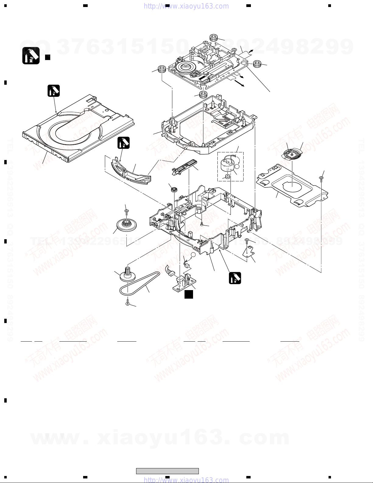
2.4 LOADING MECHANISM ASSY
23
4
A
Note :
Q
B
TEL 13942296513 QQ 376315150 892498299
C
Refer to
Q
" Application of Lubricant".
23
3
Daifree
GEM1036
7
6
3
1
22
5
1
8
12
Lubricating Oil
GYA1001
13
5
16
0
8
17
8
8
4
6
9
To DVDM
To DVDM
3
A
5
To
DVDM
CN8
4
2
8
CN4
CN2
2
Refer to
"2.4 TRAVERSE MECHANISM
ASSY-S".
19
9
18
8
20
2
9
22
9
TEL 13942296513 QQ 376315150 892498299
21
15
TEL
D
•
LOADING MECHA ASSY PARTS LIST
Mark No. Description Part No. Mark No. Description Part No.
NSP 1 LOAB Assy VWG2279
2 Traverse Mechanism Assy-S VXX2782
E
3 Loading Motor Assy VXX2505
4 Motor Pulley PNW1634
5 Carriage DC Motor / 0.3W PXM1027
6 Flexible Cable (26P) VDA1864
7 Connector Assy 2P VKP2253
8 Float Rubber VEB1327
9 Belt VEB1330
10 Stabilizer VNE2253
13942296513
14
22
3
Q
Q
7
A
11
9
1
A
16 Drive Gear VNL1923
17 SW Lever VNL1925
18 Clamper Plate VNE2251
19 Bridge VNE2252
20 Clamper VNL1924
21 Screw JGZ17P028FMC
22 Screw Z39-019
23 Tray VNL1920
22
10
Lubricating Oil
GYA1001
5
1
5
1
3
6
7
0
8
9
2
4
9
8
2
9
9
11 Loading Base VNL1917
12 Float Base DVD VNL1918
F
13 Drive Cam VNL1919
w
w
14 Gear Pulley VNL1921
15 Loading Gear VNL1922
12
w
1234
.
xia
o
y
u
1
6
XV-DV820, XV-DV620
3
.
c
o
m
Q
Q
1
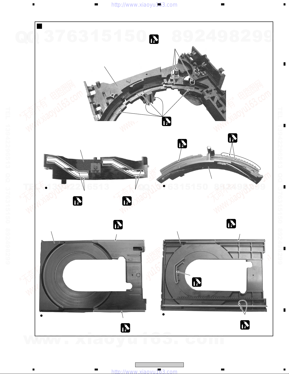
Application of Lubricant
3
7
6
3
1
5
No. 11
Loading Base
1
234
5
0
Lubricating Oil
8
GYA1001
Around the shaft
9
2
4
9
8
2
9
A
9
B
TEL 13942296513 QQ 376315150 892498299
No. 13
Drive Cam
TEL
Rear View
13942296513
Inner side of a ditch
Lubricating Oil
GYA1001
No. 23
Tray
Q
Q
Inner side of a ditch
Lubricating Oil
GYA1001
Daifree
GEM1036
Concave of unevenness
3
7
Lubricating Oil
GYA1001
Top View
1
3
6
No. 23
Tray
Lubricating Oil
GYA1001
0
5
1
5
No. 13
Drive Cam
8
9
2
Lubricating Oil
GYA1001
9
9
2
8
9
4
Daifree
GEM1036
Concave of unevenness
TEL 13942296513 QQ 376315150 892498299
C
D
w
w
Top View
w
.
xia
1
Concave of unevenness
Daifree
GEM1036
o
y
u
1
6
XV-DV820, XV-DV620
2
Bottom View
3
.
Inner side of a ditch
Daifree
GEM1036
c
o
m
3
E
Side of the rib
Daifree
GEM1036
F
13
4
1
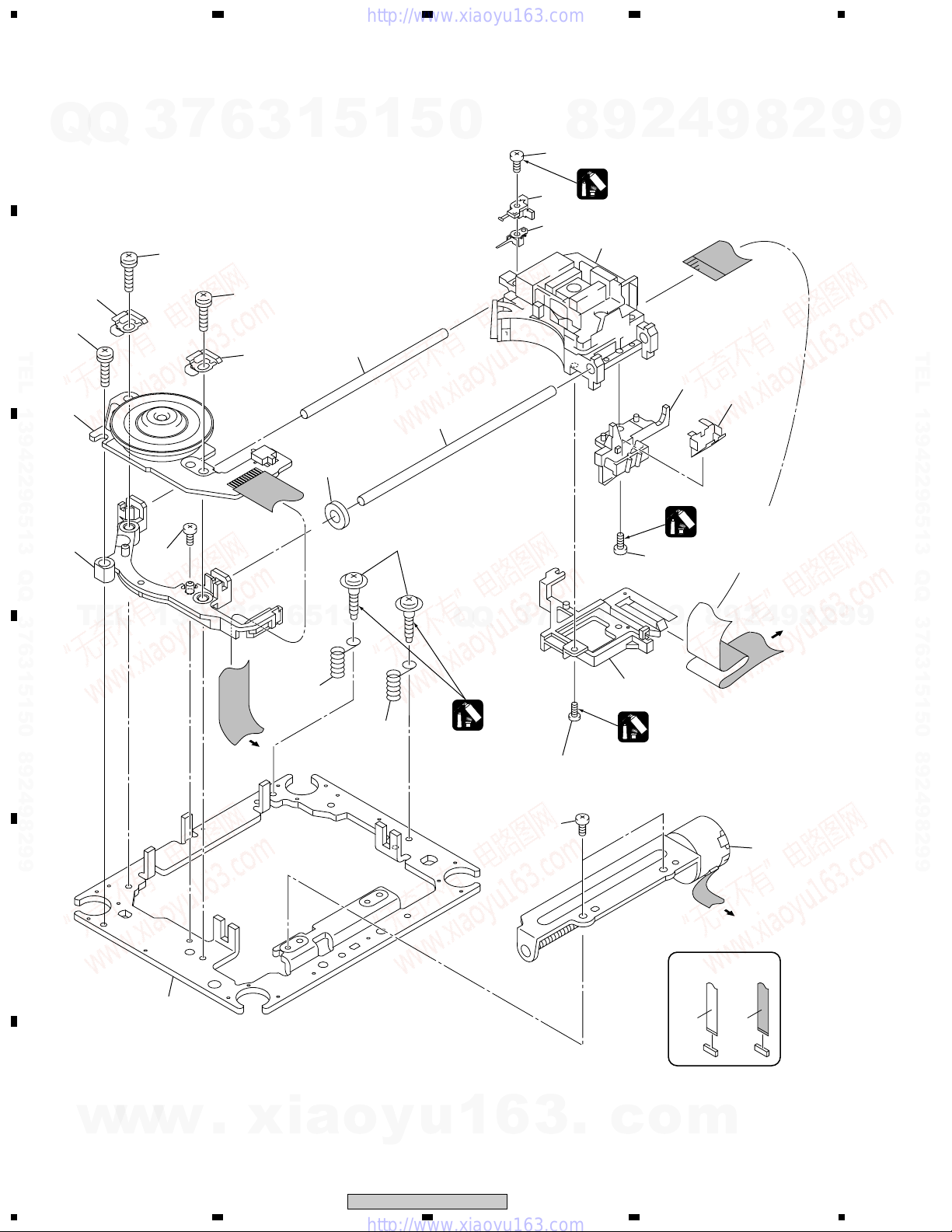
2.5 TRAVERSE MECHANISM ASSY-S
A
7
Q
Q
3
18
6
3
23
1
5
1
5
0
4
2
9
8
17 (Torque : 0.12 ± 0.01 N•m)
Silicone Adhesive
12
8
GEM1037
3
4
9
8
2
9
9
B
TEL 13942296513 QQ 376315150 892498299
C
D
10
18
1
13
TEL
16
13942296513
18
10
To DVDM
CN2
7
6
19
4 (Adjustment Screw)
3
Q
Q
5
Screw Tight
5
GYL1001
17 (Torque : 0.12 ± 0.01 N•m)
5
1
5
1
3
6
7
15
Silicone Adhesive
GEM1037
17 (Torque : 0.12 ± 0.01 N•m)
14
Silicone Adhesive
GEM1037
8
0
9
TEL 13942296513 QQ 376315150 892498299
9
To
2
4
DVDM
9
CN8
8
2
9
9
16
2
E
11
F
14
w
w
w
1234
.
xia
o
y
u
1
6
XV-DV820, XV-DV620
3
.
c
o
To DVDM
CN4
NON-CONTACT
SIDE
CONTACT SIDE
m

1
•
TRAVERSE MECHANISM ASSY-S PARTS LIST
Mark No. Description Part No.
1 Spindle Motor VXM1089
7
3
Q
Q
TEL 13942296513 QQ 376315150 892498299
2 Stepping Motor VXM1090
> 3 Pickup Assy-S OXX8003
4 Skew Screw VBA1080
5 Skew Spring VBH1335
6 Guide Bar VLL1514
7 Sub Guide Bar VLL1515
8 Hold Spring VNC1017
9 Joint Spring VNC1019
10 Support Spring VNC1020
NSP 11 Mechanism Chassis VNE2248
12 Slider VNL1811
13 Spacer VNL1913
14 Joint VNL1914
15 FFC Holder VNL1915
16 Screw BBZ20P050FZK
17 Tapping Screw OBA8009
18 Screw PMA26P100FMC
19 Damper Sheet VEB1335
6
3
1
5
1
234
5
0
8
9
2
4
9
8
2
9
A
9
B
TEL 13942296513 QQ 376315150 892498299
TEL
13942296513
Q
Q
3
7
6
3
1
5
1
5
0
8
9
2
4
9
8
2
9
C
9
D
E
w
w
w
.
xia
1
o
y
u
1
6
XV-DV820, XV-DV620
2
3
.
c
3
o
m
F
15
4
1
23
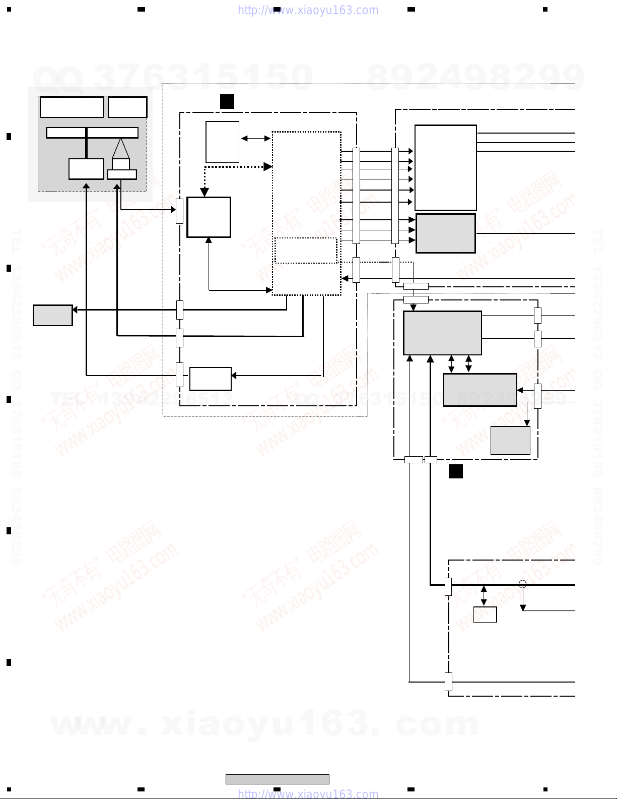
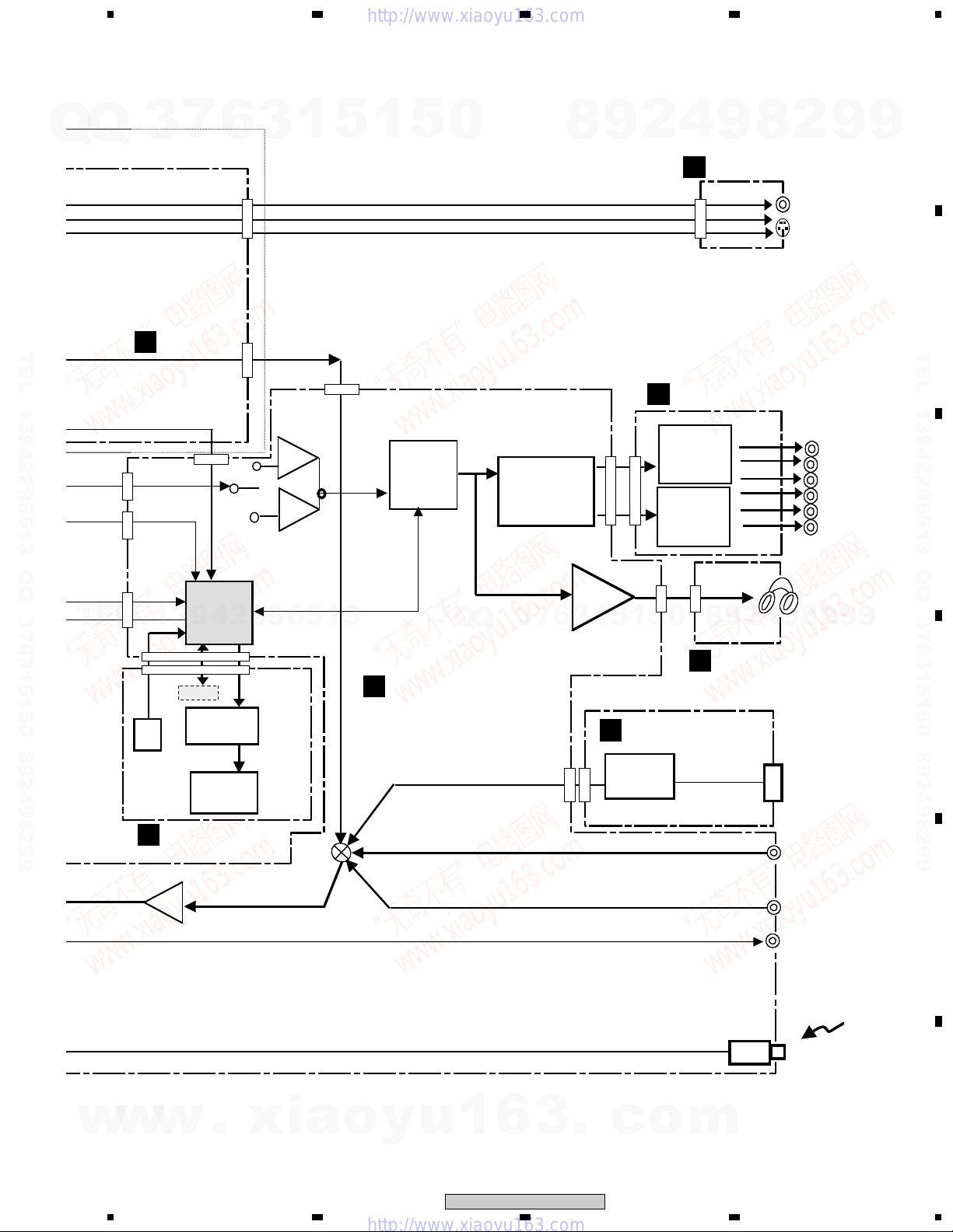
3. BLOCK DIAGRAM AND SCHEMATIC DIAGRAM
3.1 BLOCK DIAGRAM
A
Q
Q
Traverse Mechanism Assy VWT1182
DVD Traverse
Mechanism
SPDL
Motor
B
3
6
Pick UP
PU
Slider
7
TEL 13942296513 QQ 376315150 892498299
Loading Motor
ASSY
Loading
Motor
VXX2505
C
TEL
STEP
SPDL
13942296513
3
4-12
CN2
(1/2)
1-3
1-4
1-5
1
IC301
L6315
ATXXTY
CN9
CN4
CN2
(2/2)
IC251
SPDL
Driver
BA6664FM
5
B
FLASH
8M
IC603
VYW1947
1
5
DVDM ASSY
IC601
STI5519AVB B0C
Back End IC
System Control
CPU
0
Q
Q
8
DVD Module
CN25
CVBS
1534
32
11
33
13
7
26
25
5
27
9
52
22
LRCK
56
26
21
51
CN22
SPDIF
1
6
7
3
S_Y
S_C
G/Y
B/Cb
R/Cr
Data
BCK
3
9
15
11
13
7
5
9
22
26
21
1
1
CN1962
6
2
12
14
16
CN1961
5
4
2
3
1
1
4
2
Video AMP
Driver
IC1941
MM1567AJ
DAC
IC1921
PCM1742KE
CN1901
CN8002(1/2)
CODEC & DIR
IC8301
AK4586VQ
0
5
4
9
DSP
IC8101
CS493292
9
8
30,31
27,28
32,33
7,8
2
8
30,31
4
2
V
S_Y
S_C
9
CN8003
5,7
CN8002
CN8001
8
9
2
9
9
TEL 13942296513 QQ 376315150 892498299
9
ROM
1,3
5
D
E
CN8002
(2/2)
CN8003
D
CN5620
(2/2)
1,3
CN5612
(2/2)
6
DD/DTS
DSP ASSY
ATT
10dB
IC3002
F
16
w
w
w
1234
.
xia
o
y
u
1
6
XV-DV820, XV-DV620
3
.
c
o
m
5
7
Q
Q
TEL 13942296513 QQ 376315150 892498299
3
C
DVD IF ASSY
6
CN1902
V
S_Y
10
S_C
CN1901
28,30
8
6
3
1
21,23
5
CN5501
1
678
5
0
8
9
2
V
S_Y
S_C
AMP ASSY
F
4
9
POWER ASSY
J
CN8001
8
10
6
8
2
9
Video OUT
S-Video OUT
(S2/S1 Video out)
A
9
B
TEL 13942296513 QQ 376315150 892498299
5,7
TEL
IC3051
CN5502
CN5620
(1/2)
IC3059
CN5612
(1/2)
CN5613
IR
K
IC3003
System
U-com
IC5501
13942296513
PDC098A
Key
FL
Control
IC5601
MSM9202-01
FL Tube
Display
DISPLAY ASSY
0dB
7.6dB
IC3061
CN5611
CN5601
IC3001
E-VOL
IC3060
M62446FP
CONTROL ASSY
G
Analog Selector
Q
Q
Equalizer
(ANDREW)
IC3056,IC3057
IC3058
6
7
3
HP
Amp
3
CN5701
CN5501
CN5531
CN3902
5
1
5
1
IC3901
FM/AM TUNER
E
MODULE
CN201
FM/AM
TUNER
3ch Amp
IC3301
STK402-270
3ch Amp
IC3401
STK402-270
CN3901
1,3
8
0
M
4
2
9
HP ASSY
Head Phone
8
9
Antenna IN
LINE 1
FL
FR
C
SW
SL
SR
2
9
C
9
D
w
w
w
.
xia
5
o
y
u
1
6
XV-DV820, XV-DV620
6
3
.
c
7
o
m
TV
E
LINE OUT
Optical IN
F
17
8
1
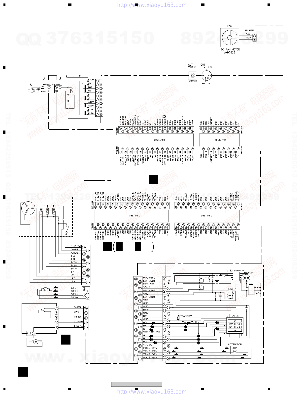
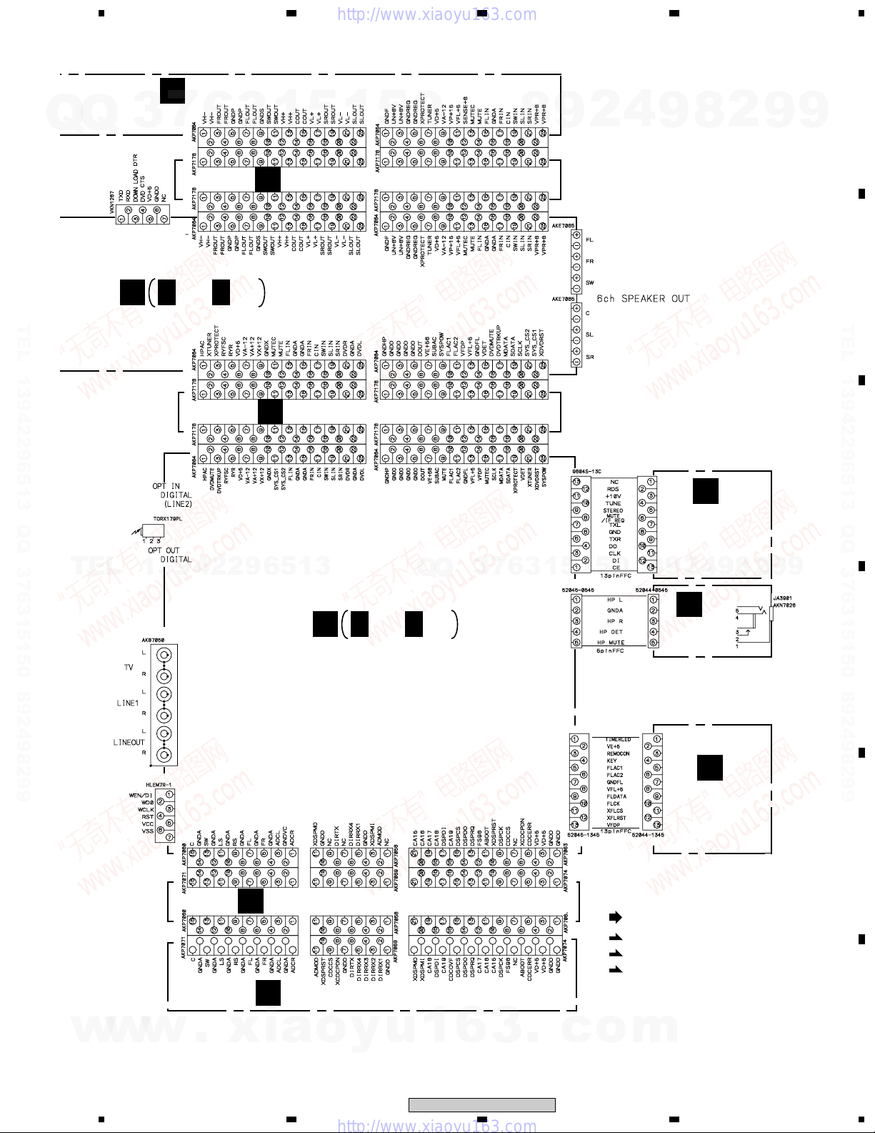
3.2 LOAB ASSY and OVERALL WIRING DIAGRAM
A
7
Q
Q
3
6
3
23
1
5
1
5
0
8
9
2
4
4
9
CN3501
8
2
9
9
CN1961
CN11
CN5102CN1901
Q
DVD IF ASSY (AWM7677)
C
3
Q
AN1
CN2
POWER CODE
B
TEL 13942296513 QQ 376315150 892498299
C
MYXJN : ADG1154
NVXJN : ADG1156
TEL
SPINDLE MOTOR
: VXM1089
13942296513
7
JA8803
6
3
1
5
1
5
JA8802
0
8
9
2
CN8001
CN1902
9
4
CN1962
8
2
9
TEL 13942296513 QQ 376315150 892498299
9
D
CN601
S5B-PH-K
LOADING
MOTOR
ASSY
: VXX2505
w
(S)
(S)
(S)
(S)
A
.
STEPPING
MOTOR
E
(CARRIAGE)
: VXM1090
S101
: VSK1011
CN602
S2B-PH-K
F
LOAB ASSY
w
w
(VWG2279)
CN22
CN2
B
CN4
CN9
xia
B1/2- B 2/2
CN8
o
y
u
DVDM ASSY (AWM7750)
PICKUP ASSY-S (OXX8003)
(RF)
(RF)
(RF)
1
(RF)
(RF)
(RF)
6
(F)
(T)
3
(RF)
(RF)
(RF)
(T)
(F)
.
(RF)
(RF)
(RF)
(F)
(T)
(T)
(F)
c
o
(RF)
(RF)
(F)
(T)
m
VKN1318
(T)
CN25
(F)
18
A
1234
XV-DV820, XV-DV620
Q
5
Note : When ordering service parts, be sure to refer to "EXPLODED VIEWS and PARTS LIST" or "PCB PARTS LIST"
AMP ASSY (AWM7720)
F
Q
3
7
6
CN3001
3
1
5
1
678
5
CN3002
0
8
9
2
4
9
8
2
9
A
9
CN3011
TRADE1 ASSY (AWU8036)
L
CN8003
J
TEL 13942296513 QQ 376315150 892498299
TEL
13942296513
CN3021
CN3031
J 1/2- J 2/2
CN5531
CN5521
CN5511
CN5501
JA8602
POWER ASSY (AWU8032)
TRADE2 ASSY (AWU8043)
H
CN3012
CN3022
CN3032
CN5522
CN5512
CN5502 CN5532
Q
Q
3
7
6
3
CN3401
5
1
CN3902
CN3301
CN5701
5
1
CN201
0
CN3901
E
FM/AM TUNER
MODULE
(AXQ7228)
4
2
9
8
9
8
2
9
B
TEL 13942296513 QQ 376315150 892498299
C
9
JA3001
CN5504
CN5620
CN5619
CN5618
CN8003
G
G1/3- G 3/3
CONTROL ASSY
(AWU8051 : XV-DV820/KUCXJN)
(AWU8041 : XV-DV620/KUCXJN)
TRADE3 ASSY (AWU8044)
I
DSP ASSY (AWX8059)
D
CN5612
CN5616
CN5614
CN8002
CN5611
CN5613
CN5617
CN5615
CN8001
M
HP ASSY
(AWU8037)
K
DISPLAY ASSY
(AWU8035)
CN5601
(RF)
: RF SIGNAL ROUTE
(F)
: FOCUS SERVO LOOP LINE
(T)
: TRACKING SERVO LOOP LINE
(S)
: SLIDER SERVO LOOP LINE
D
E
w
w
w
.
xia
5
o
y
u
1
6
XV-DV820, XV-DV620
6
3
.
c
7
o
m
F
19
8
1
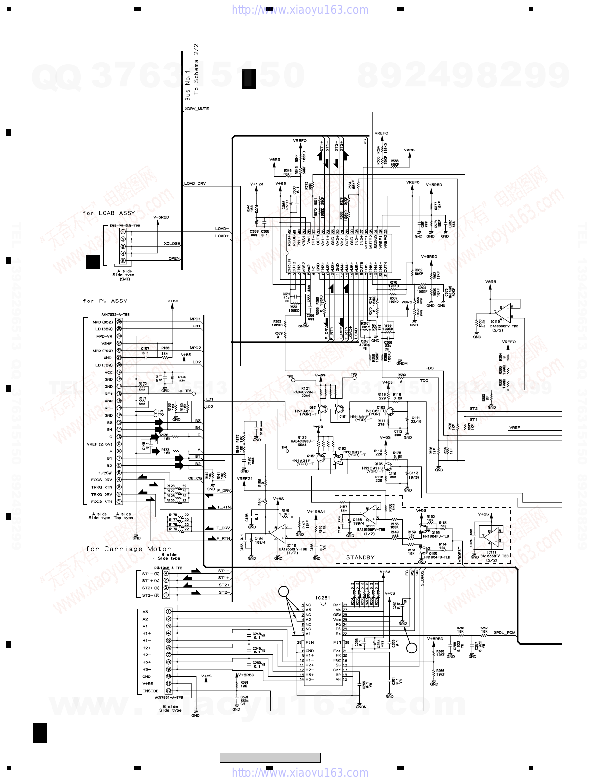
3.3 DVDM ASSY(1/2)
A
Q
Q
B
3
7
6
3
23
1
5
B 1/2
1
DVDM ASSY(1/2) (AWM7750)
5
0
2
9
8
(S)
(S)
(S)
(S)
4
4
9
8
2
9
9
TEL 13942296513 QQ 376315150 892498299
C
TEL
PICKUP ASSY-S
D
CN9
CN601
A
CN8
13942296513
(RF)
(RF)
(RF)
(RF)
(RF)
(RF)
(F)
(T)
(T)
(F)
(F)
(T)
IC351 M56788AFP
FTS DRIVER
Q
Q
(F)
3
(F)
(T)
7
(T)
6
3
1
5
1
5
0
8
9
2
4
9
8
2
9
TEL 13942296513 QQ 376315150 892498299
9
E
F
w
B 1/2
20
(T)
(T)
CN4
(S)
(S)
(S)
STEPPING
MOTOR
SPINDLE MOTOR
w
w
1234
.
(S)
CN2
xia
o
y
XV-DV820, XV-DV620
u
3
1
IC251 BA6664FM
SPINDLE DRIVE IC
6
3
.
c
2
o
m
Q
Q
3
7
5
6
3
1
1
678
5
0
5
8
9
2
4
9
8
2
9
A
9
B
TEL 13942296513 QQ 376315150 892498299
B 2/2
TEL
13942296513
L6315ATXXTY (RAM)
FRONT END IC
IC301
Q
Q
3
7
6
3
1
(RF)
: RF SIGNAL ROUTE
: DATA SIGNAL ROUTE
(F)
: FOCUS SERVO LOOP LINE
(T)
: TRACKING SERVO LOOP LINE
(S)
: SLIDER SERVO LOOP LINE
WORK SRAM (1M)
9
8
0
5
1
5
IC302
K6T1008V2E-TB70
8
9
4
2
2
9
TEL 13942296513 QQ 376315150 892498299
C
9
D
w
w
w
1
: The power supply is shown with the marked box.
.
xia
5
(RF)
(RF)
o
y
u
1
6
XV-DV820, XV-DV620
6
3
.
4
c
7
o
m
E
F
B 1/2
21
8
1
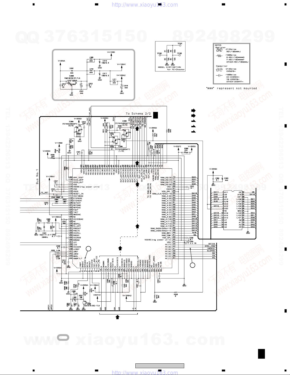
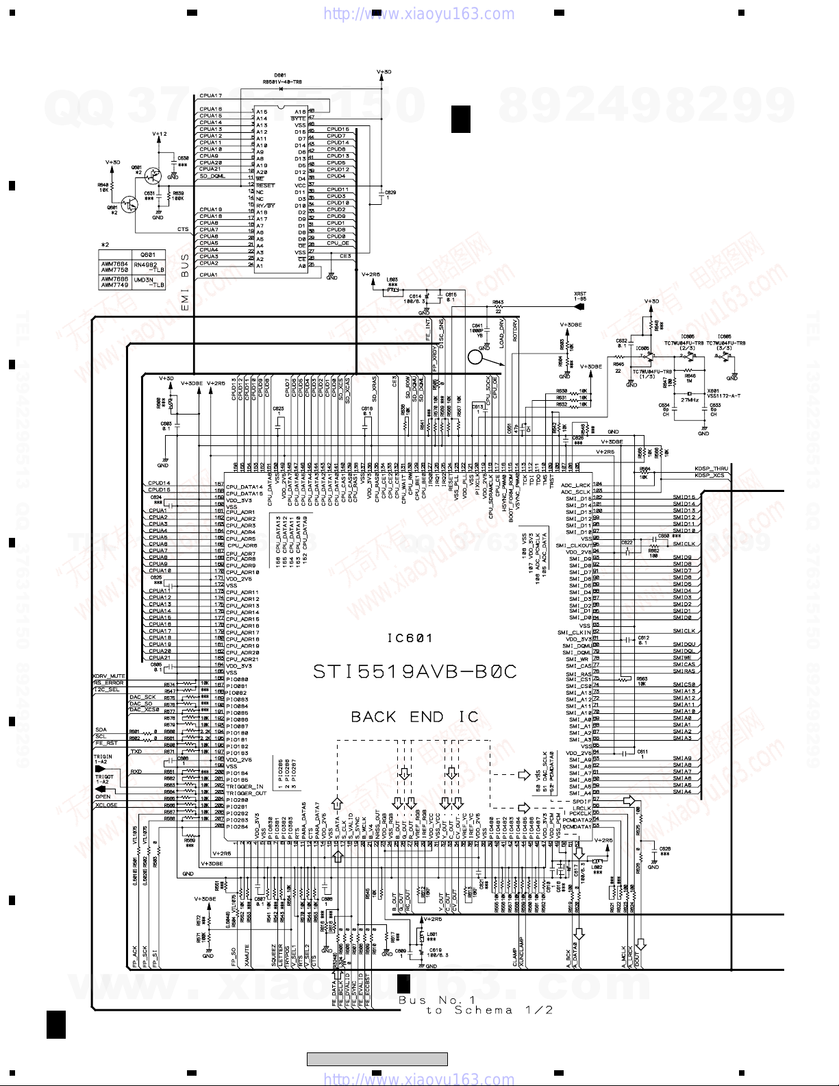
3.4 DVDM ASSY(2/2)
A
Q
Q
3
7
6
3
23
1
5
1
5
0
B 2/2
8
2
9
DVDM ASSY(2/2)
(AWM7750)
4
4
9
8
2
9
9
B
TEL 13942296513 QQ 376315150 892498299
C
TEL
D
13942296513
IC603 VYW1999
(MBM29LV800TA-90PFTN)
PGM 8M FLASH MEMORY
Q
Q
3
5
7
6
3
1
5
1
5
0
8
9
2
4
9
8
2
9
TEL 13942296513 QQ 376315150 892498299
9
E
F
w
B 2/2
22
(R/Cr)
(V)
(S_Y)
6
(S_C)
3
.
(D)
c
o
(D)
(D)
m
(G/Y)
(B/Cb)
w
w
1234
.
xia
o
y
XV-DV820, XV-DV620
u
B 1/2
1
Q
Q
3
7
5
6
3
1
1
678
: The power supply is shown with the marked box.
5
0
5
8
9
2
4
9
8
2
9
A
9
B
TEL 13942296513 QQ 376315150 892498299
IC604
K4S641632F-TC75
64M SDRAM
(D)
TEL
13942296513
(V)
(V)
(V)
(R/Cr)
(S_C)
(R/Cr)
(S_Y)
Q
Q
(R/Cr)
(G/Y)
(B/Cb)
3
7
6
3
1
5
1
5
(V)
(S_C)
(S_Y)
(R/Cr)
(G/Y)
(B/Cb)
(D)
(D)(D)
0
CN22
8
CN25
9
2
4
CN1961
C
8
9
9
9
2
CN1962
C
TEL 13942296513 QQ 376315150 892498299
C
D
w
w
(S_C)
(S_Y)
w
(S_C)
(S_Y)
.
xia
5
(G/Y)
(B/Cb)
(G/Y)
(B/Cb)
o
y
u
1
6
XV-DV820, XV-DV620
6
3
.
c
7
: DATA SIGNAL ROUTE
(V)
: V SIGNAL ROUTE
(S_C)
: S-VIDEO OUT C SIGNAL ROUTE
(S_Y)
: S-VIDEO OUT Y SIGNAL ROUTE
(R/Cr)
: R/Cr SIGNAL ROUTE
(G/Y)
: G/Y SIGNAL ROUTE
(B/Cb)
: B/Cb SIGNAL ROUTE
: AUDIO SIGNAL ROUTE
(D)
: AUDIO (DIGITAL) SIGNAL ROUTE
o
m
E
F
B 2/2
23
8
1
3.5 DVD IF ASSY
A
Q
Q
CN1961
3
7
6
3
23
1
DVD IF ASSY (AWM7677)
C
5
1
5
0
8
9
2
4
RN1903
4
9
8
2
9
9
CN22
B
TEL 13942296513 QQ 376315150 892498299
C
D
B
TEL
(D)
13942296513
CN1962
(D)
Q
Q
(G/Y)
(B/Cb)
(R/Cr)
(S_C)
(S_Y)
3
(V)
7
6
3
1
5
1
5
0
RN1903
8
9
(V)
2
12
4
9
10
9
7
8
(S_C)
8
11
(G/Y)
(B/Cb)
(R/Cr)
(S_Y)
2
9
TEL 13942296513 QQ 376315150 892498299
9
CN25
B
E
F
w
w
w
.
(V)
(S_C)
(S_Y)
(R/Cr)
(G/Y)
(B/Cb)
xia
o
RN1903
y
RN2903
RN1903
u
1
RN2903
6
3
.
c
o
UN5212
m
C
24
1234
XV-DV820, XV-DV620
Q
Q
3
5
: The power supply is shown with the marked box.
7
6
3
1
5
1
678
5
0
8
9
2
4
9
8
2
9
A
9
265
(D)
3 4
TEL 13942296513 QQ 376315150 892498299
TEL
13942296513
1
UN5212
UN5212
7
3
Q
Q
6
3
1
5
(D)
CN1901
5
1
0
8
9
J
2
CN5102
8
9
4
2
9
B
TEL 13942296513 QQ 376315150 892498299
C
9
w
w
w
.
xia
o
(V)
(S_Y)
(G/Y)
(B/Cb)
(R/Cr)
(V)
: VIDEO SIGNAL ROUTE
(S_Y)
: S-Y VIDEO SIGNAL ROUTE
(S_C)
: S-C VIDEO SIGNAL ROUTE
(D)
: DIGITAL AUDIO SIGNAL ROUTE
y
u
1
(S_C)
6
3
CN1902
CN8001
J
(G/Y)
: COMPONENT VIDEO G/Y SIGNAL ROUTE
(B/Cb)
: COMPONENT VIDEO B/Cb SIGNAL ROUTE
(R/Cr)
: COMPONENT VIDEO R/Cr SIGNAL ROUTE
.
c
o
m
D
E
F
C
5
XV-DV820, XV-DV620
6
7
8
25
1
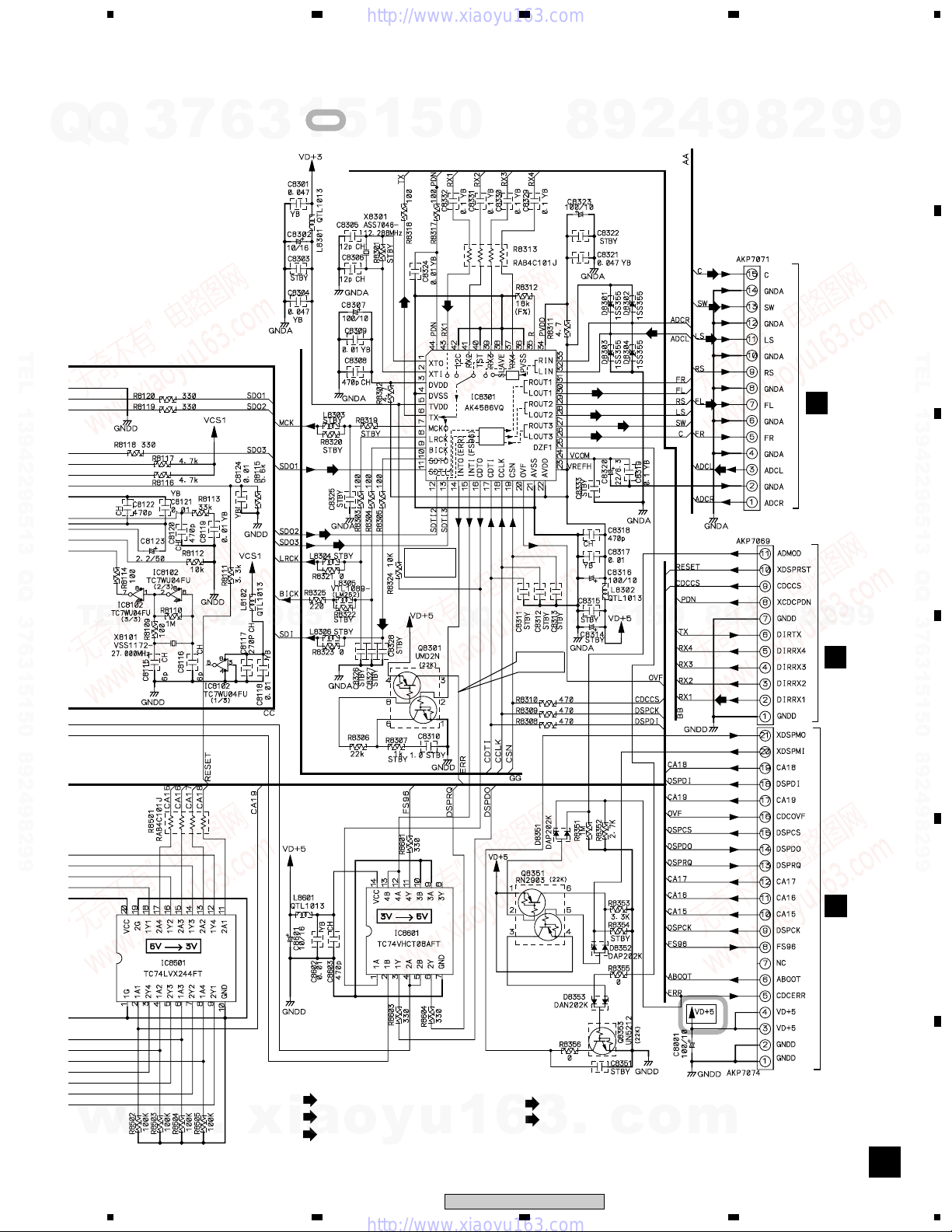
3.6 DSP ASSY
A
7
Q
Q
B
3
DSP ASSY (AWX8059)
D
6
3
23
1
5
1
5
0
8
9
2
4
4
9
8
2
9
9
TEL 13942296513 QQ 376315150 892498299
C
TEL
D
13942296513
Q
Q
3
7
6
3
1
5
1
5
0
TEL 13942296513 QQ 376315150 892498299
(D)
(D)
(D)
9
9
2
8
9
4
2
9
8
(D)
(D)
(D)
E
F
D
26
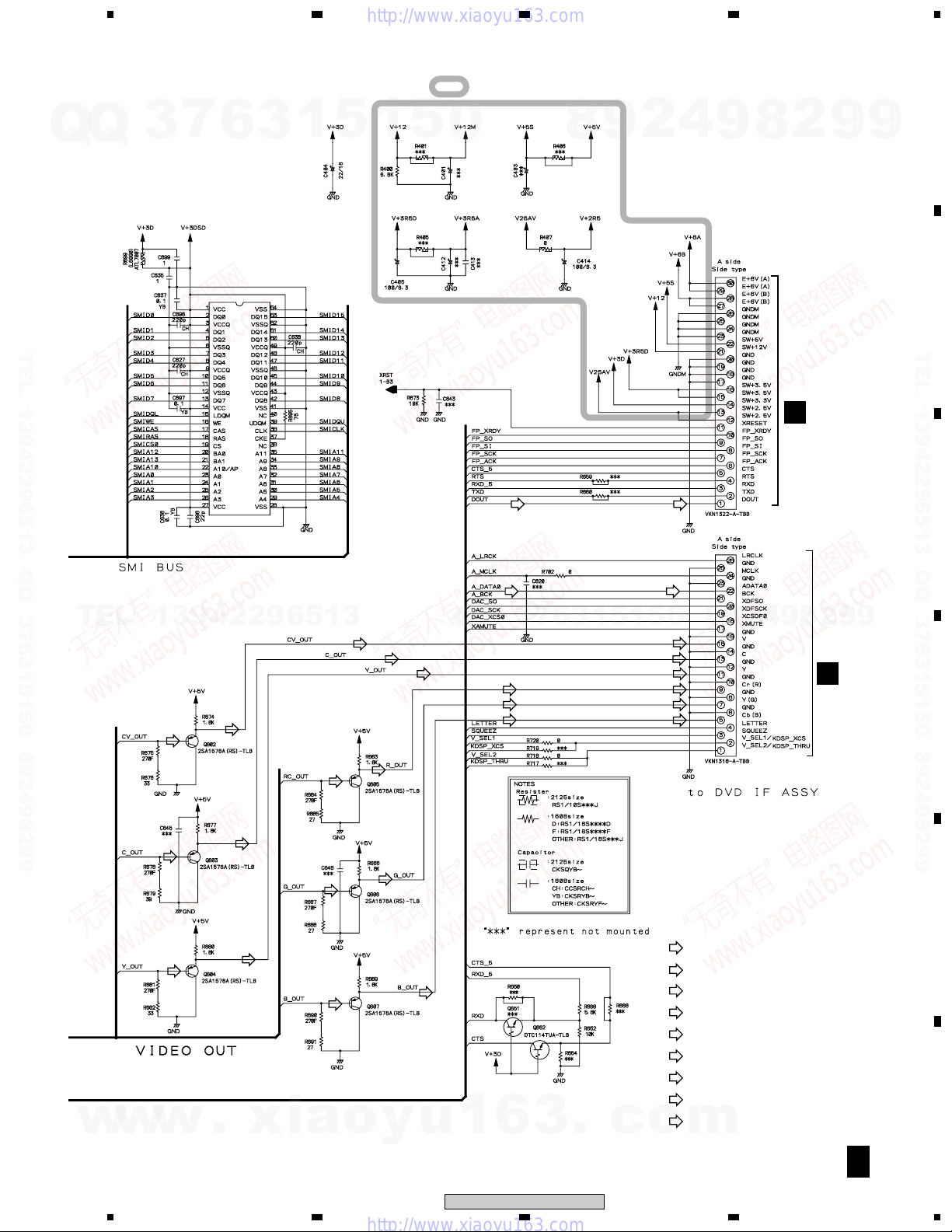
w
w
w
1234
.
xia
o
y
u
1
6
XV-DV820, XV-DV620
3
.
c
o
m
5
678
7
Q
Q
TEL 13942296513 QQ 376315150 892498299
3
6
3
1
: The power supply is shown with the marked box.
5
1
5
0
(D)
(D)
A/D
D/A
(D)
(D)
(D)
CODEC/
DIR
8
(FL)
(SL)
(C)
9
(SW)
2
4
(C)
(SW)
(SL)
(FL)
9
CN8003
CN8002
8
2
9
9
CN5618
I
A
B
TEL 13942296513 QQ 376315150 892498299
C
TEL
13942296513
(D)
Q
Q
7
3
D IN
UNLOCK : 5V
LOCK : 0V
6
3
1
5
1
5
0
8
9
(D)
2
4
9
8
9
2
CN5612
I
CN5615
I
9
D
E
w
w
w
.
xia
5
(D)
: DIGITAL AUDIO SIGNAL ROUTE
(FL)
: FL ch AUDIO SIGNAL ROUTE
(SL)
o
: SL ch AUDIO SIGNAL ROUTE
y
(C)
(SW)
u
1
6
XV-DV820, XV-DV620
6
: C ch AUDIO SIGNAL ROUTE
: SW ch AUDIO SIGNAL ROUTE
3
.
c
o
7
CN8001
m
F
D
27
8
1
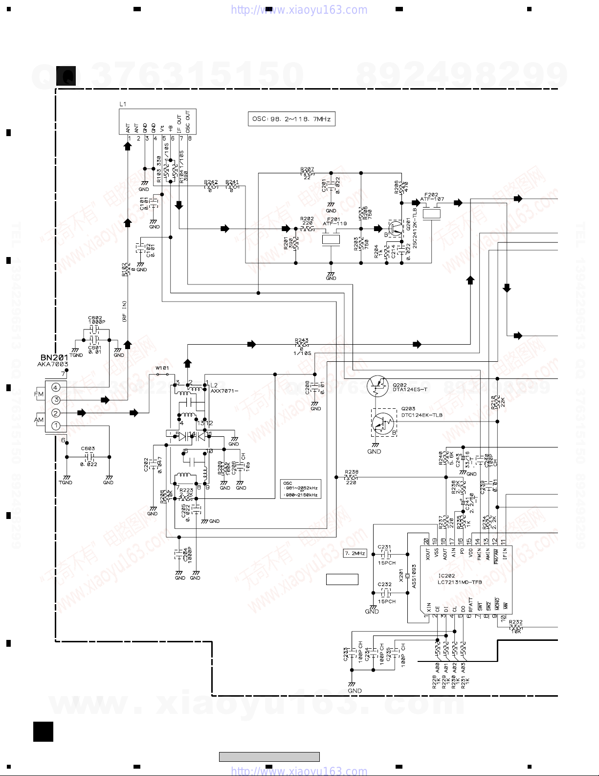
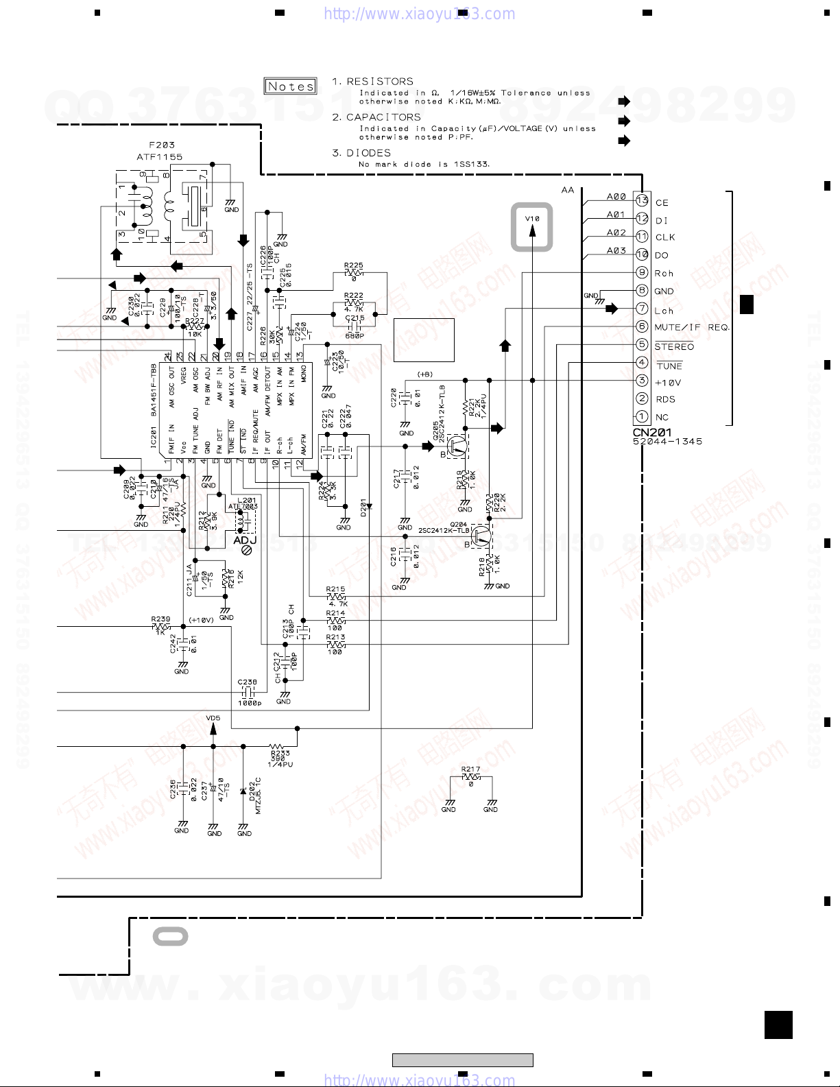
3.7 FM/AM TUNER MODULE
A
FM/AM TUNER MODULE (AXQ7228)
Q
E
Q
3
7
6
FM FRONT END
: AXF7003
(FM)
3
23
1
5
1
5
0
8
9
2
4
4
9
8
2
9
9
B
TEL 13942296513 QQ 376315150 892498299
C
(FM) (FM)
TEL
D
13942296513
(FM)
(AM)
(AM)
(FM)
(AM)
(FM)
(FM) (FM)
3
Q
Q
7
6
3
1
(FM) (FM)
(AM)(AM)
5
1
5
0
8
9
(AM)
2
4
9
(AM)
8
(FM)
(FM)
2
9
TEL 13942296513 QQ 376315150 892498299
9
E
F
w
w
w
.
xia
o
y
u
1
6
PLL IC
3
.
c
o
m
E
28
1234
XV-DV820, XV-DV620
5
678
7
(FM)
(AM)
(AM)
3
Q
Q
TEL 13942296513 QQ 376315150 892498299
6
(AM)
(AM)
3
(AM)
(AM)
1
5
(TX)
1
5
0
IC201
AM/FM IF
+MPX IC
(TX)
8
(TX)
(TX)
9
2
(TX)
: AUDIO SIGNAL ROUTE (TUNER)
(AM)
4
(FM)
(TX)
8
9
: AM SIGNAL ROUTE
: FM SIGNAL ROUTE
2
9
9
G
3/3
CN5701
A
B
TEL 13942296513 QQ 376315150 892498299
C
TEL
13942296513
1SS133
Q
Q
3
7
6
3
1
5
1
5
0
8
9
2
4
9
8
2
9
9
D
E
w
w
w
: The power supply is shown with the marked box.
.
xia
5
o
y
u
1
6
XV-DV820, XV-DV620
6
3
.
c
7
o
m
F
E
29
8
1
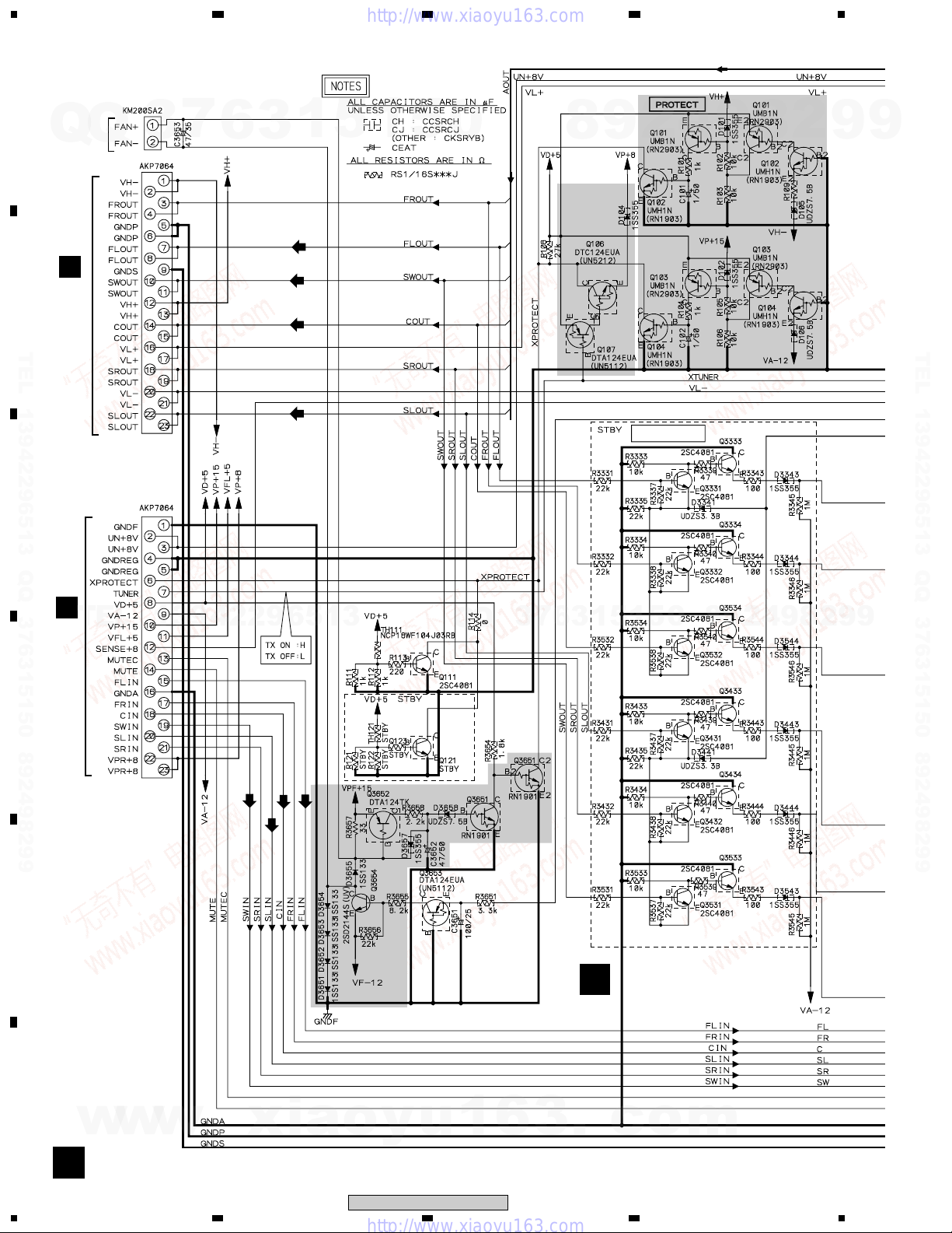
3.8 AMP ASSY
23
4
Q
CN3651
3
CN3001
CN3002
7
6
3
1
(FL)
(SW)
(C)
(SL)
5
1
5
0
A
to FAN
Q
Motor
L
CN3011
B
TEL 13942296513 QQ 376315150 892498299
C
8
4
2
9
Non Distortion Circuit
4
9
8
2
820
3
9
9
TEL 13942296513 QQ 376315150 892498299
L
CN3012
TEL
D
E
13942296513
(C)
(SW)
(FL)
(SL)
6
Q
Q
3
7
6
3
1
F
5
1
8
0
5
AMP ASSY
(AWM7720)
9
2
4
9
8
2
9
9
F
w
w
w
.
xia
o
y
u
1
6
3
.
c
o
m
F
30
1234
XV-DV820, XV-DV620
 Loading...