

Pioneer X-HM11DAB-K User Manual
X-HM21DAB
-K
X-HM11DAB
X-HM11
CD Receiver System
-K
-K
Discover the benefits of registering your product online at
http://www.pioneer.co.uk
Operating Instructions
(or http://www.pioneer.eu).
CAUTION
TO PREVENT THE RISK OF ELECTRIC SHOCK, DO NOT
REMOVE COVER (OR BACK). NO USER-SERVICEABLE
PARTS INSIDE. REFER SERVICING TO QUALIFIED
SERVICE PERSONNEL.
D3-4-2-1-1_B1_En
WARNING
This equipment is not waterproof. To prevent a fire or
shock hazard, do not place any container filled with
liquid near this equipment (such as a vase or flower
pot) or expose it to dripping, splashing, rain or
moisture.
D3-4-2-1-3_A1_En
WARNING
To prevent a fire hazard, do not place any naked flame
sources (such as a lighted candle) on the equipment.
D3-4-2-1-7a_A1_En
VENTILATION CAUTION
When installing this unit, make sure to leave space
around the unit for ventilation to improve heat radiation
(at least 25 cm at top, 10 cm at rear, and 5 cm at each
side).
WARNING
Slots and openings in the cabinet are provided for
ventilation to ensure reliable operation of the product,
and to protect it from overheating. To prevent fire
hazard, the openings should never be blocked or
covered with items (such as newspapers, table-cloths,
curtains) or by operating the equipment on thick carpet
or a bed.
D3-4-2-1-7b*_A1_En
Operating Environment
Operating environment temperature and humidity:
+5 °C to +35 °C (+41 °F to +95 °F); less than 85 %RH
(cooling vents not blocked)
Do not install this unit in a poorly ventilated area, or in
locations exposed to high humidity or direct sunlight
(or strong artificial light)
D3-4-2-1-7c*_A1_En
WARNING
Store small parts out of the reach of children and
infants. If accidentally swallowed, contact a doctor
immediately.
D41-6-4_A1_En
This product is for general household purposes. Any
failure due to use for other than household purposes
(such as long-term use for business purposes in a
restaurant or use in a car or ship) and which requires
repair will be charged for even during the warranty
period.
K041_A1_En
CAUTION
The STANDBY/ON switch on this unit will not
completely shut off all power from the AC outlet.
Since the power cord serves as the main disconnect
device for the unit, you will need to unplug it from the
AC outlet to shut down all power. Therefore, make
sure the unit has been installed so that the power
plug can be easily unplugged from the AC outlet in
case of an accident. To avoid fire hazard, the power
cord should also be unplugged from the AC outlet
when left unused for a long period of time (for
example, when on vacation).
D3-4-2-2-2a*_A1_En
POWER-CORD CAUTION
Handle the power cord by the plug. Do not pull out the
plug by tugging the cord and never touch the power
cord when your hands are wet as this could cause a
short circuit or electric shock. Do not place the unit, a
piece of furniture, etc., on the power cord, or pinch the
cord. Never make a knot in the cord or tie it with other
cords. The power cords should be routed such that they
are not likely to be stepped on. A damaged power cord
can cause a fire or give you an electrical shock. Check
the power cord once in a while. When you find it
damaged, ask your nearest PIONEER authorized service
center or your dealer for a replacement.
S002*_A1_En
Do not install your speakers overhead on the ceiling or
wall. The grill is designed to be detachable, and as such
it may fall and cause damage or personal injury if
installed overhead.
SGK004_A1_En
CAUTION
This product is a class 1 laser product classified
under the Safety of laser products, IEC 60825-1:2007.
CLASS 1 LASER PRODUCT
D58-5-2-2a_A1_En

Information for users on collection and disposal of old equipment and used batteries
These symbols on the products, packaging, and/or accompanying documents mean
that used electrical and electronic products and batteries should not be mixed with
general household waste.
For proper treatment, recovery and recycling of old products and used batteries,
please take them to applicable collection points in accordance with your national
legislation.
By disposing of these products and batteries correctly, you will help to save valuable
resources and prevent any potential negative effects on human health and the
environment which could otherwise arise from inappropriate waste handling.
For more information about collection and recycling of old products and batteries,
please contact your local municipality, your waste disposal service or the point of sale
where you purchased the items.
These symbols are only valid in the European Union.
For countries outside the European Union:
If you wish to discard these items, please contact your local authorities or dealer and
ask for the correct method of disposal.
K058a_A1_En
Symbol examples
for batteries
Symbol for
equipment
Pb

Thank you for buying this Pioneer product.
Please read through these operating instructions so that you will know how to operate your model properly. After you
have finished reading the instructions, put them in a safe place for future reference.
Contents
01 Before you start
What’s in the box . . . . . . . . . . . . . . . . . . . . . . . . . . . . . . . 5
Loading the batteries in the remote control . . . . . . . . . 5
Using the remote control . . . . . . . . . . . . . . . . . . . . . . . . . 5
02 Part names and functions
Remote control . . . . . . . . . . . . . . . . . . . . . . . . . . . . . . . . 6
Speaker system . . . . . . . . . . . . . . . . . . . . . . . . . . . . . . . . 7
Front panel . . . . . . . . . . . . . . . . . . . . . . . . . . . . . . . . . . . . 8
Display . . . . . . . . . . . . . . . . . . . . . . . . . . . . . . . . . . . . . . . 9
03 Connections
Speaker connection . . . . . . . . . . . . . . . . . . . . . . . . . . . 10
Connecting antenna
(X-HM21DAB, X-HM11DAB) . . . . . . . . . . . . . . . . . . . . . 11
Connecting antennas (X-HM11) . . . . . . . . . . . . . . . . . . 11
Using external antennas . . . . . . . . . . . . . . . . . . . . . . . . . 11
Plugging in . . . . . . . . . . . . . . . . . . . . . . . . . . . . . . . . . . . 11
04 Getting started
To turn the power on . . . . . . . . . . . . . . . . . . . . . . . . . . . 12
Setting the clock . . . . . . . . . . . . . . . . . . . . . . . . . . . . . . 12
General control . . . . . . . . . . . . . . . . . . . . . . . . . . . . . . . 12
Input function. . . . . . . . . . . . . . . . . . . . . . . . . . . . . . . . . . 12
Display brightness control . . . . . . . . . . . . . . . . . . . . . . . 12
Volume auto setting. . . . . . . . . . . . . . . . . . . . . . . . . . . . . 12
Volume control. . . . . . . . . . . . . . . . . . . . . . . . . . . . . . . . . 12
Muting. . . . . . . . . . . . . . . . . . . . . . . . . . . . . . . . . . . . . . . . 12
Sound controls . . . . . . . . . . . . . . . . . . . . . . . . . . . . . . . 13
Equalizer . . . . . . . . . . . . . . . . . . . . . . . . . . . . . . . . . . . . . . 13
P.BASS control . . . . . . . . . . . . . . . . . . . . . . . . . . . . . . . . 13
Bass/treble control . . . . . . . . . . . . . . . . . . . . . . . . . . . . . 13
Setting the wake-up timer . . . . . . . . . . . . . . . . . . . . . . . 13
Calling the wake-up timer . . . . . . . . . . . . . . . . . . . . . . . . 14
Cancelling the wake-up timer. . . . . . . . . . . . . . . . . . . . . 14
Using the wake-up timer . . . . . . . . . . . . . . . . . . . . . . . . . 14
Using the sleep timer . . . . . . . . . . . . . . . . . . . . . . . . . . 14
Using Headphones . . . . . . . . . . . . . . . . . . . . . . . . . . . . 14
05 iPod/iPhone/iPad playback (XHM21DAB only)
Confirming what iPod/iPhone/iPad models are
supported . . . . . . . . . . . . . . . . . . . . . . . . . . . . . . . . . . . . 15
Connecting your iPod/iPhone/iPad . . . . . . . . . . . . . . . 15
Connecting iPod/iPhone/iPad using supplied stand . . 15
Playing iPod/iPhone/iPad . . . . . . . . . . . . . . . . . . . . . . . 16
06 Disc playback
Playing discs or files . . . . . . . . . . . . . . . . . . . . . . . . . . . 17
Advanced CD or MP3/WMA disc playback . . . . . . . . . 18
Direct track search . . . . . . . . . . . . . . . . . . . . . . . . . . . . . 18
Repeat play. . . . . . . . . . . . . . . . . . . . . . . . . . . . . . . . . . . . 18
Random play . . . . . . . . . . . . . . . . . . . . . . . . . . . . . . . . . . 18
Programmed play (CD or MP3/WMA) . . . . . . . . . . . . . . 19
About downloading MP3/WMA . . . . . . . . . . . . . . . . . . . 19
About folder playback order . . . . . . . . . . . . . . . . . . . . . . 19
Specify the folder to play. . . . . . . . . . . . . . . . . . . . . . . . . 20
Switch the display contents . . . . . . . . . . . . . . . . . . . . . . 20
4
En
07 USB playback
Playing USB storage devices . . . . . . . . . . . . . . . . . . . . 21
Repeat play. . . . . . . . . . . . . . . . . . . . . . . . . . . . . . . . . . . . 21
Random play . . . . . . . . . . . . . . . . . . . . . . . . . . . . . . . . . . 21
Specify the folder to play. . . . . . . . . . . . . . . . . . . . . . . . . 22
Switch the display contents . . . . . . . . . . . . . . . . . . . . . . 22
Playing in the desired order (Programmed Play) . . . . 22
08 Using the tuner
Listening to the radio broadcasts . . . . . . . . . . . . . . . . 23
Tuning. . . . . . . . . . . . . . . . . . . . . . . . . . . . . . . . . . . . . . . . 23
Saving station presets. . . . . . . . . . . . . . . . . . . . . . . . . . . 23
To recall a memorised station . . . . . . . . . . . . . . . . . . . . 24
To scan the preset stations. . . . . . . . . . . . . . . . . . . . . . . 24
To erase entire preset memory. . . . . . . . . . . . . . . . . . . . 24
Using the Radio Data System (RDS) . . . . . . . . . . . . . . 24
An introduction to RDS. . . . . . . . . . . . . . . . . . . . . . . . . . 24
Searching for RDS programs. . . . . . . . . . . . . . . . . . . . . 24
Information provided by RDS . . . . . . . . . . . . . . . . . . . . . 25
Using the Auto Station Program Memory (ASPM). . . . 25
Notes for RDS operation. . . . . . . . . . . . . . . . . . . . . . . . . 25
Listening to the DAB+ . . . . . . . . . . . . . . . . . . . . . . . . . 26
About DAB+ (Digital Audio Broadcasting) . . . . . . . . . 26
Auto Scan. . . . . . . . . . . . . . . . . . . . . . . . . . . . . . . . . . . . . 26
Selecting a station in the station list . . . . . . . . . . . . . . . 26
Manual tune. . . . . . . . . . . . . . . . . . . . . . . . . . . . . . . . . . . 26
Changing the information display . . . . . . . . . . . . . . . . . 27
Memorising a station . . . . . . . . . . . . . . . . . . . . . . . . . . . 27
DAB Frequency table (BAND III) . . . . . . . . . . . . . . . . . . 27
09 Other connections
Connecting auxiliary components . . . . . . . . . . . . . . . . 28
10 Additional information
Troubleshooting . . . . . . . . . . . . . . . . . . . . . . . . . . . . . . . 29
Playable discs and formats . . . . . . . . . . . . . . . . . . . . . 31
Regarding copy protected CDs . . . . . . . . . . . . . . . . . . . 31
Supported audio file formats . . . . . . . . . . . . . . . . . . . . . 31
Cautions on use . . . . . . . . . . . . . . . . . . . . . . . . . . . . . . . 31
When moving this unit . . . . . . . . . . . . . . . . . . . . . . . . . . 31
Place of installation. . . . . . . . . . . . . . . . . . . . . . . . . . . . . 31
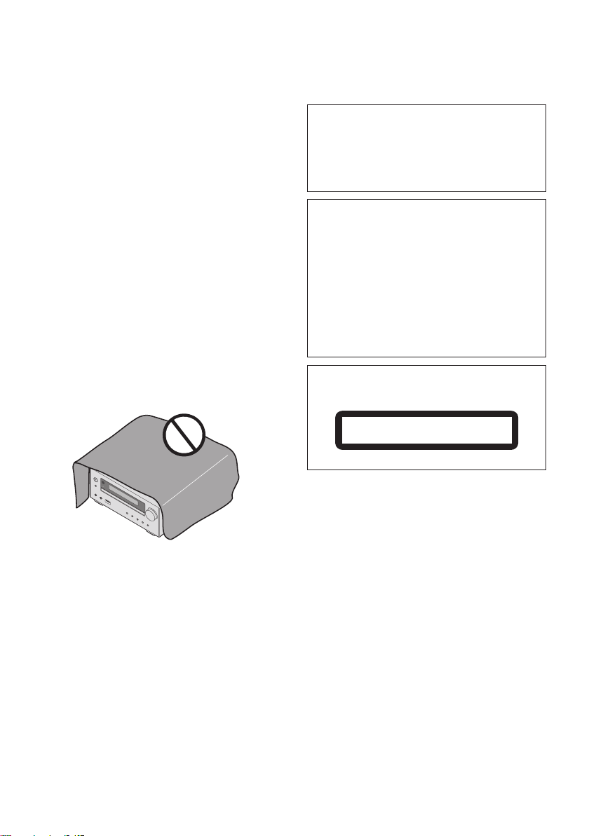
Do not place objects on this unit . . . . . . . . . . . . . . . . . . 32
About condensation . . . . . . . . . . . . . . . . . . . . . . . . . . . . 32
Cleaning the product. . . . . . . . . . . . . . . . . . . . . . . . . . . . 32
Cleaning the lens. . . . . . . . . . . . . . . . . . . . . . . . . . . . . . . 32
Handling discs . . . . . . . . . . . . . . . . . . . . . . . . . . . . . . . . 32
Storing . . . . . . . . . . . . . . . . . . . . . . . . . . . . . . . . . . . . . . . 32
Cleaning discs . . . . . . . . . . . . . . . . . . . . . . . . . . . . . . . . . 32
About specially shaped discs. . . . . . . . . . . . . . . . . . . . . 32
About iPod/iPhone/iPad . . . . . . . . . . . . . . . . . . . . . . . . 33
Restoring all the settings to the defaults . . . . . . . . . . 33
Specifications . . . . . . . . . . . . . . . . . . . . . . . . . . . . . . . . 34
Before you start 01
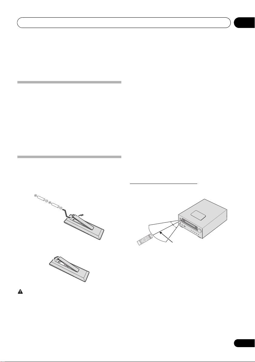
30°
7 m
30°
Chapter 1:
Before you start
• Do not heat batteries, disassemble them, or throw them
What’s in the box
Please confirm that the following accessories are in the box
when you open it.
• Remote Control
•Power cord
• AM antenna cable (X-HM11)
• FM wire antenna (X-HM11)
• DAB/FM wire antenna (X-HM21DAB, X-HM11DAB)
• AAA batteries (R03) x 2
• iPad stand (X-HM21DAB only)
• Warranty card
• Operating instructions (this document)
Loading the batteries in the
remote control
1 Open the rear lid and load the batteries as
illustrated below.
into flames or water.
• Batteries may have different voltages, even if they are the
same size and shape. Do not use different types of
batteries together.
• To prevent leakage of battery fluid, remove the batteries
if you do not plan to use the remote control for a long
period of time (1 month or more). If the fluid should leak,
wipe it carefully off the inside of the case, then insert new
batteries. If a battery should leak and the fluid should get
on your skin, flush it off with large quantities of water.
• When disposing of used batteries, please comply with
governmental regulations or environmental public
institution’s rules that apply in your country/area.
• WARNING
Do not use or store batteries in direct sunlight or other
excessively hot place, such as inside a car or near a
heater. This can cause batteries to leak, overheat,
explode or catch fire. It can also reduce the life or
performance of batteries.
Using the remote control
The remote has a range of about 7 m at an angle of about 30º
from the remote sensor.
2 Close the rear lid.
CAUTION
• When inserting the batteries, make sure not to damage
the springs on the battery’s terminals. This can cause
batteries to leak or over heat.
• Do not use any batteries other than the ones specified.
Also, do not use a new battery together with an old one.
• When loading the batteries into the remote control, set
them in the proper direction, as indicated by the polarity
marks ( and ).
INPUT
Keep in mind the following when using the remote control:
• Make sure that there are no obstacles between the
remote and the remote sensor on the unit.
• Remote operation may become unreliable if strong
sunlight or fluorescent light is shining on the unit’s
remote sensor.
• Remote controllers for different devices can interfere
with each other. Avoid using remotes for other
equipment located close to this unit.
• Replace the batteries when you notice a fall off in the
operating range of the remote.
5
En
Part names and functions02
4
5
1
3
2
6
7
8
12
17
13
14
9
10
11
16
15
STANDBY/ON
CD USB TUNER AUDIO IN
DISPLAY FOLDER
MENU
PRESET VOLUME
ST/MONO ASPM PTY DISPLAY
+
MUTE
TUNE–
TUNE+
DIMMER
–
+
–
MEMORY
/PROGRAM
123
456
789
0
BT AUDIO
CLOCK/TIMER
SLEEP
EQUALIZER
P.B A S S
BASS/TREBLE
RANDOM
CLEAR REPEAT
OPEN/CLOSE
RDS
ENTER
SCAN ENTER DISPLAY
DAB
Chapter 2:
Part names and functions
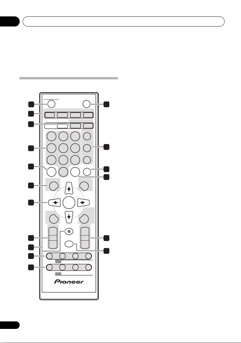
Remote control
6
En
1 STANDBY/ON
Switches the receiver between standby and on (page 12).
2 Input function buttons
Use to select the input source to this receiver (pages 16, 17,
21, 23, and 28).
3 CD Receiver control buttons
CLOCK/TIMER
Use for setting the clock, as well as for setting and
checking the timers (page 12).
SLEEP
See Using the sleep timer on page 14.
4 Numeric buttons (0 to 9)
Use to enter the number (page 18).
5
CLEAR
Use to clear the programmed play (page 19).
6 CD Receiver control buttons
DISPLAY
Press to change the display for songs playing back from
CD or USB (page 20).
FOLDER
Use to select the folder of the MP3/WMA disc or USB
mass storage device (page 19).
MENU
Use to access the menu.
MEMORY/PROGRAM
Use to memory or program the MP3/WMA disc
(page 19).
7/// (TUNE +/–), ENTER
Use to select/switch system settings and modes, and to
confirm actions.
Use TUNE +/– can be used to find radio frequencies
(page 23).
8
PRESET +/–
Use to select preset radio stations (page 24).
9
MUTE
Mutes/unmutes the sound (page 12).
10 Playback control buttons
Use to control each function after you have selected it using
the input function buttons (page 17).
Part names and functions 02
1
2
3
11
Tuner
control buttons
ST/MONO
Use to switch the sound mode between stereo and
monaural. (page 23)
RDS ASPM
Use to search for RDS Auto station program memory
(page 24).
RDS PTY
Use to search for RDS program types (page 24).
RDS DISPLAY
Press to change the RDS display for information mode
(page 24).
DAB SCAN
Use to scan for DAB radio station (page 26).
DAB ENTER
Use to confirm the DAB radio station (page 26).
DAB DISPLAY
Press to change the DAB display for information mode
(page 27).
12 OPEN/CLOSE
Use to open or close the disc tray (page 17).
13 Sound control buttons
Adjust the sound quality (page 13).
14 RANDOM
Randomize order of track playback from a CD, iPod or USB
(page 18).
15
REPEAT
Press to change the repeat play setting from a CD, iPod or
USB (page 18).
16 Volume control buttons
Use to set the listening volume (page 12).
17
DIMMER
Dims or brightens the display. The brightness can be
controlled in four steps (page 12).
Note
•The BT AUDIO button is not available for this unit.
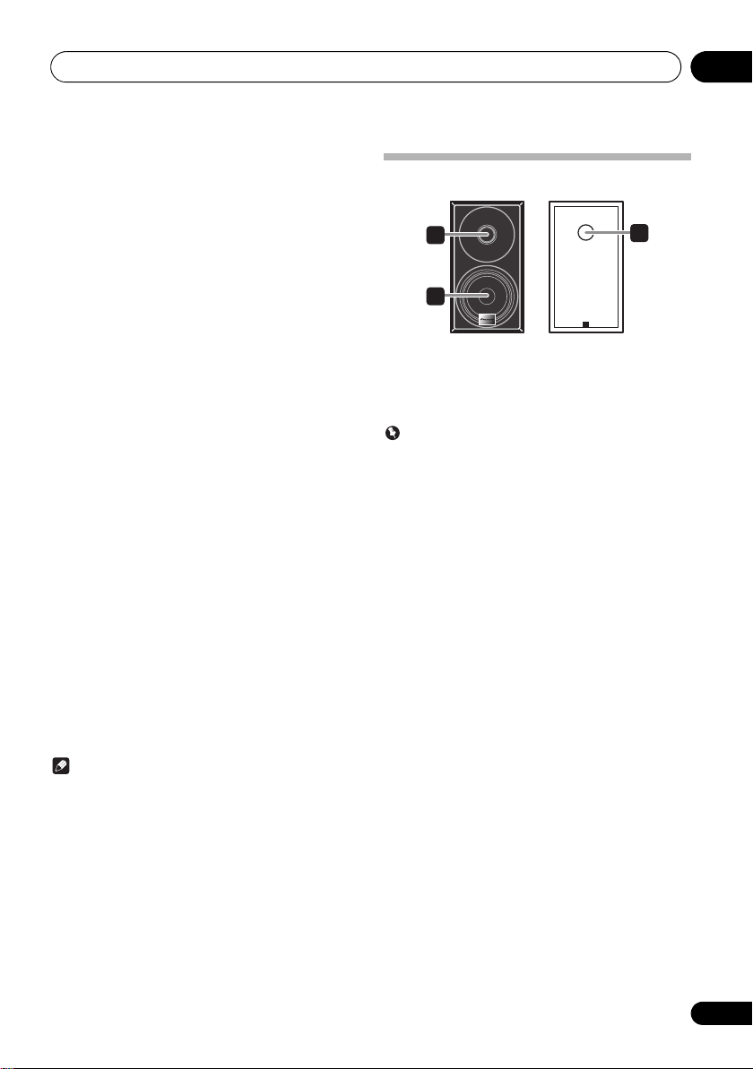
Speaker system
1 Tweeter
2Woofer
3 Bass Reflex Duct
Important
• Speaker grille cannot be removed.(X-HM11DAB, XHM11)
• Make sure nothing comes into contact with the speaker
diaphragms when you remove the speaker grilles. (XHM21DAB)
7
En
Part names and functions02
STANDBY/ON
INPUT
VOLUME
PHONES AUDIO IN
TIMER
X-HM21
X-HM21DAB
7 86 9 11 1210
2 51 3 4
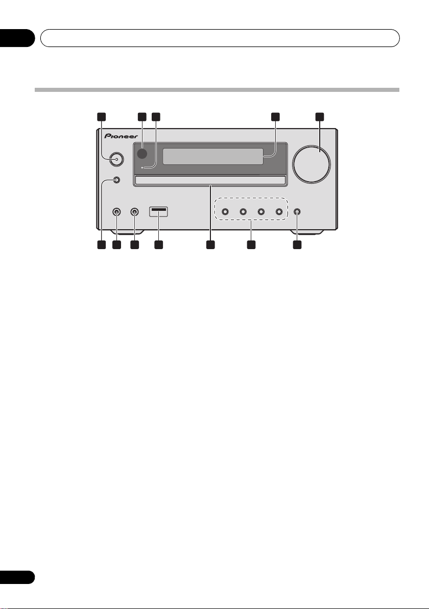
Front panel
1 STANDBY/ON button
Switches the receiver between standby and on (page 12).
2 Remote sensor
Receives the signals from the remote control.
3TIMER
Lights when the unit power is off but when the timer setting is
activated.
4 Character display
See Display on page 9.
indicator
5 Volume control
Use to set the listening volume (page 12).
6 INPUT
Selects the input source.
7 Headphone socket
Use to connect headphones. When the headphones are
connected, there is no sound output from the speakers
(page 14).
button
8 AUDIO IN socket
Use to connect an auxiliary component using a stereo
minijack cable (page 28).
9 USB terminal (X-HM21DAB)
Use to connect your USB mass storage device or Apple iPod/
iPhone/iPad as an audio source (page 21).
USB terminal (X-HM11DAB, X-HM11)
Use to connect your USB mass storage device as an audio
source (page 21).
10 Disc tray
Place the disc, label side up (page 17).
11 Playback control buttons
Select the desired track or file to be played back. Stop current
playback. Stop playback or resume playback from the point
where it was paused.
12 Disc tray open/close button
Use to open or close the disc tray (page 17).
8
En
Part names and functions 02
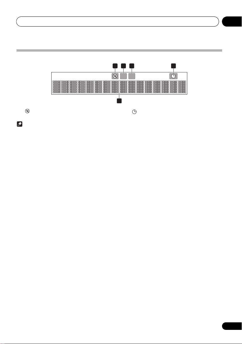
Display
1 32 4
5
1
Lights when the sound is muted.
Note
• The mute icon will be displayed in red.
2
Start playback.
3
Pause playback.
4
Timer function is set.
5 Character display
Displays various system information.
En
9
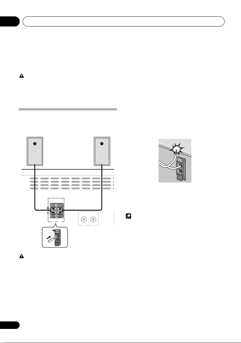
Connections03
Left
speaker
Right
speaker
This unit’s rear panel
Chapter 3:
Connections
CAUTION
• Be sure to turn off the power and unplug the power cord
from the power outlet whenever making or changing
connections.
• Connect the power cord after all the connections
between devices have been completed.
Speaker connection
• Push open the tabs and insert exposed wire.
• Connect the black wire to () terminal, and the red wire
to the (+) terminal.
SPEAKERS
LINE
IN
RL
R
L
• Do not attach these speakers to the wall or ceiling. They
may fall off and cause injury.
• These speakers are magnetically shielded. However,
depending on the installation location, color distortion
may occur if the speaker system is installed extremely
close to the screen of a television set. If this happens,
turn off the television set, and then turn it on after 15 to
30 minutes. If the problem persists, move the speaker
system away from the television set.
• Make sure that the speaker cable cores do not become
exposed and make contact with other cable cores. This
may cause malfunction of the product.
• Do not allow the speaker cable core to come into contact
with the receiver body.
- If the speaker cable core comes into contact with any
metal portion of the receiver’s body, it may damage the
speakers and cause smoke and fire.
Insert speaker cables securely into the terminals and
check that the cable does not come out of easily.
Note
• There is no difference between L and R speakers.
CAUTION
• These speaker terminals carry HAZARDOUS LIVE
voltage. To prevent the risk of electric shock when
connecting or disconnecting the speaker cables,
disconnect the power cord before touching any
uninsulated parts.
• Do not connect any speakers other than those supplied
to this system.
• Do not connect the supplied speakers to any amplifier
other than the one supplied with this system.
Connection to any other amplifier may result in
malfunction or fire.
10
En
Connections 03
ANTENNA
DAB/FM
AM
LOOP
ANTENNA
FM
UNBAL
75 Ω
2
1
3
4
fig. a
fig. b
One-touch PAL
connector
75 coaxial
cable
To AC outlet
This unit’s rear panel
Power cord
3 Place the AM antenna on a flat surface and
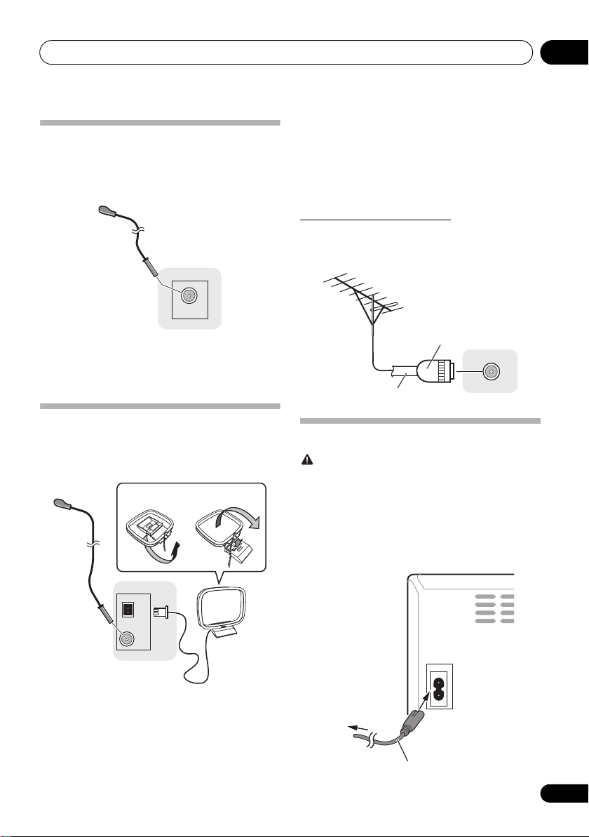
Connecting antenna
(X-HM21DAB, X-HM11DAB)
Connect the DAB/FM wire antenna as shown below. To
improve reception and sound quality, connect external
antenna (see Using external antennas below).
in a direction giving the best reception.
4 Connect the FM wire antenna into the FM
antenna socket.
For best results, extend the FM antenna fully and fix to a wall
or door frame. Don’t drape loosely or leave coiled up.
Using external antennas
To improve FM reception
Use a PAL connector (not supplied) to connect an external FM
antenna.
1 Connect the DAB/FM wire antenna into the
DAB/FM antenna socket.
For best results, extend the DAB/FM antenna fully and fix to a
wall or door frame. Don’t drape loosely or leave coiled up.
Connecting antennas (X-HM11)
Connect the AM loop antenna and the FM wire antenna as
shown below. To improve reception and sound quality,
connect external antennas (see Using external antennas
below).
1 Connect the AM antenna wires.
Hold the terminal part of the wire when connecting.
2 Fix the AM loop antenna to the attached
stand.
To fix the stand to the antenna, bend in the direction indicated
by the arrow (fig. a) then clip the loop onto the stand (fig. b).
ANTENNA
DAB/FM
Plugging in
CAUTION
• Do not use any power cord other than the one supplied
with this unit.
• Do not use the supplied power cord for any purpose
other than that described below.
Before making or changing the connections, switch off the
power and disconnect the power cord from the AC outlet.
After you’ve finished making all connections, plug the unit
into an AC outlet.
AC IN
11
En
 Loading...