

Pioneer XDV-P650 User Manual
English
Español
Português (B)
Français
Italiano
Nederlands
XDV-P650
This product conforms to new cord colors.
Los colores de los cables de este producto se conforman
con un nuevo código de colores.
As cores dos fios deste produto seguem um novo padrão
de cores.
INSTALLATION MANUAL
INSTALLATION MANUAL

2
Contents
Connecting the Units ................................ 2
Connecting the system (1).................................. 4
Connecting the system (2).................................. 6
When Connecting the Display with RCA Input
Jacks .......................................................... 7
When Using a Display Connected Rear Video
Output.......................................................... 8
Connecting the Power Cord .............................. 9
Installation ................................................ 10
MODE Switch Setting...................................... 10
Installing the hide-away unit .......................... 10
DIN Front/Rear-mount .................................... 11
DIN Front-mount ............................................ 11
DIN Rear-mount .............................................. 12
Mounting with Brackets .................................. 13
Installing the Remote Sensor............................ 13
WARNING:
• To avoid the risk of accident and the
potential violation of applicable laws,
the front DVD or TV (sold separately)
feature should never be used while the
vehicle is being driven. Also, Rear
Displays should not be in a location
where it is a visible distraction to the
driver.
• In some countries or states the viewing
of images on a display inside a vehicle
even by persons other than the driver
may be illegal. Where such regulations
apply, they must be obeyed and this
unit’s DVD features should not be used.
CAUTION:
• PIONEER does not recommend that
you install or service your display (sold
separately) yourself. Installing or servicing the product may expose you to risk
of electric shock or other hazards. Refer
all installation and servicing of your display to authorized Pioneer service personnel.
• Secure all wiring with cable clamps or
electrical tape. Do not allow any bare
wiring to remain exposed.
• Do not drill a hole into the engine compartment to connect the yellow lead of
the unit to the vehicle battery. Engine
vibration may eventually cause the insulation to fail at the point where the wire
passes from the passenger compartment
into the engine compartment. Take
extra care in securing the wire at this
point.
• It is extremely dangerous to allow the
display (sold separately) lead to become
wound around the steering column or
gearshift. Be sure to install the display
in such a way that it will not obstruct
driving.
• Make sure that wires will not interfere
with moving parts of the vehicle, such as
the gearshift, parking brake or seat sliding mechanism.
• Do not shorten any leads. If you do, the
protection circuit may fail to work
properly.
• Do not install the display (sold separately) where it may (i) obstruct the
driver’s vision, (ii) impair the performance of any of the vehicle’s
operating systems or safety features,
including air bags, hazard lamp buttons or (iii) impair the driver’s ability to safely operate the vehicle.
Connecting the Units
English
Español
Português (B)
Français
Italiano
Nederlands
3
Note:
• This unit is for vehicles with a 12-volt battery and
negative grounding. Before installing it in a recreational vehicle, truck, or bus, check the battery
voltage.
• To avoid shorts in the electrical system, be sure to
disconnect the ≠ battery cable before beginning
installation.
• Refer to the owner’s manual for details on
connecting the power amp and other units, then
make connections correctly.
• Secure the wiring with cable clamps or adhesive
tape. To protect the wiring, wrap adhesive tape
around them where they lie against metal parts.
• Route and secure all wiring so it cannot touch any
moving parts, such as the gear shift, handbrake
and seat rails. Do not route wiring in places that
get hot, such as near the heater outlet. If the insulation of the wiring melts or gets torn, there is a
danger of the wiring short-circuiting to the vehicle
body.
• Don’t pass the yellow lead through a hole into the
engine compartment to connect to the battery.
This will damage the lead insulation and cause a
very dangerous short.
• Do not shorten any leads. If you do, the protection
circuit may fail to work when it should.
• Never feed power to other equipment by cutting
the insulation of the power supply lead of the unit
and tapping into the lead. The current capacity of
the lead will be exceeded, causing overheating.
• When replacing the fuse, be sure to only use a
fuse of the rating prescribed on the fuse holder.
• To prevent incorrect connection, the input side of
the IP-BUS connector is blue, and the output side
is black. Connect the connectors of the same colors correctly.
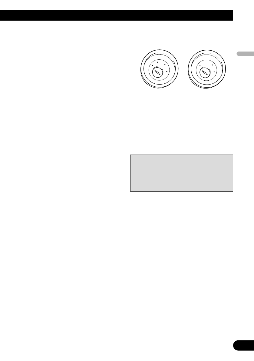
• This unit cannot be installed in a vehicle that
does not have an ACC (accessory) position on
the ignition switch.
• The black lead is ground. Please ground this lead
separately from the ground of high-current products such as power amps.
If you ground the products together and the
ground becomes detached, there is a risk of damage to the products or fire.
No ACC positionACC position
• Cords for this product and those for other products may be different colors even if they have
the same function. When connecting this product to another product, refer to the supplied
manuals of both products and connect cords
that have the same function.
C
C
A
O
F
N
F
O
S
T
A
R
T
O
F
N
F
O
S
T
A
R
T

4
Connecting the Units
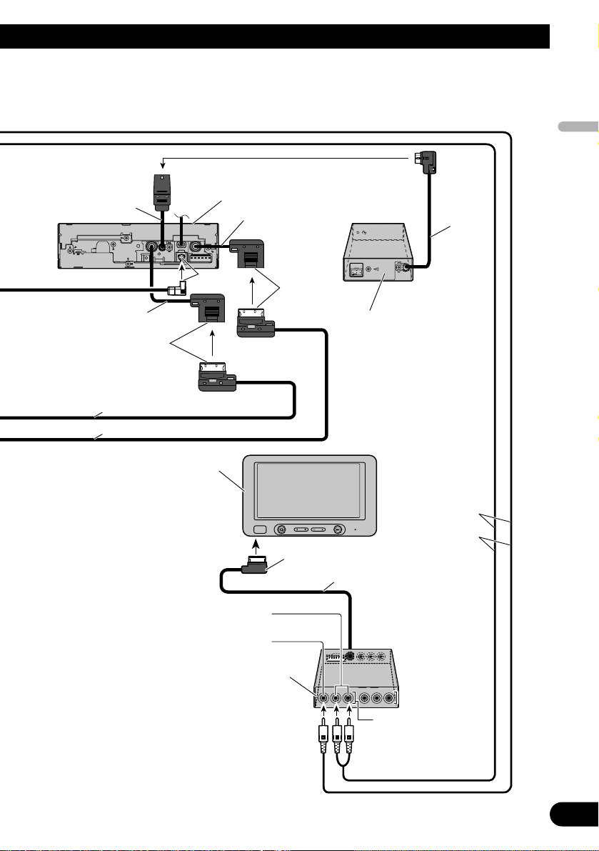
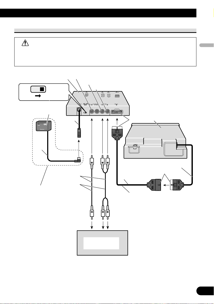
Connecting the system (1)
Blue
Violet
6 m
6 m
Hide-away unit (supplied with
AVH-P7850DVD)
Optical cable
(sold separately)
Black
Blue
IP-BUS cable (supplied)
6 m
Black
STAND ALONE
IP BUS
Hide-away unit
This product
25 pin cable (supplied)
Depending on where you install,
this cable is not used.
Black
Black 20 cm
2.7 m
9 cm
Black
AV-BUS cable (supplied)
6 m
Blue
Blue
Black
Red
White
Yellow
When using an optical cable, insert a clamp
(supplied with the optical cable) in the hole
and secure the cable.
English
Español
Português (B)
Français
Italiano
Nederlands
5
Vio let
Blue
30-pin cable (supplied with AVH-P7850DVD)
30-pin cable (supplied with AVH-P7850DVD)
40 cm
15 cm
40 cm
1 m
Multi-CD control DSP High Power DVD-A/DVD-V/
VCD/CD/MP3/WMA/AAC/DivX/JPEG Player
with RDS Tuner (AVH-P7850DVD) (sold separately)
Power supply box
(supplied with AVH-P7850DVD)
Blue
White
3 m
16:9 Rear Seat Entertainment Display
(AVD-W6200) (sold separately)
Hide-away unit (supplied with AVD-W6200)
VIDEO1 INPUT
VIDEO1 RCA audio input
(white, red)
VIDEO1 RCA video input
(yellow)
RCA cable (supplied)
6 m
6
Connecting the Units
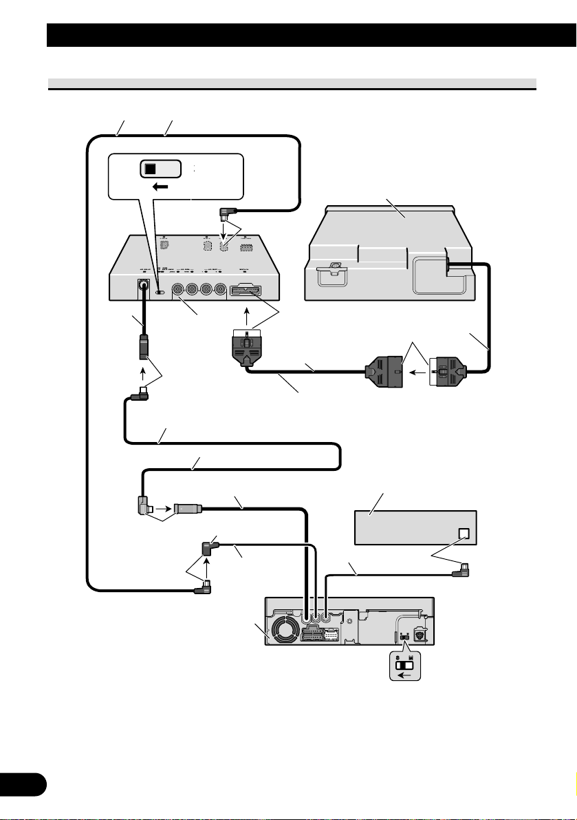
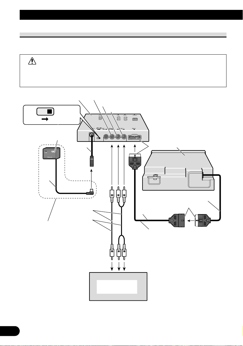
Connecting the system (2)
IP-BUS cable (supplied)
3 m
ST
AND
E
US
Depending
Head Unit
(sold
ly)
3 m
AV-BUS cable (supplied)
40
cm
Blue
IP B
9 cm
AND
ALON
Hide-away unit
Black
Blue
Blue
Black
Black
2.7 m
25 pin cable (supplied)
this cable is not used.
15 cm
This product
Black
on where you install,
separate
40 cm
20 cm
7 inch Wide AV System Display /
DVD Player (AVX-P7650DVD)
(sold separately)
7
English
Español
Português (B)
Français
Italiano
Nederlands
When Connecting the Display with RCA Input Jacks
WARNING
• NEVER install the display in a location that enables the Driver to watch the DVD or
Video CD while Driving.
• NEVER connect audio output (AUDIO OUT) to sold separately power amp.
E
Display
with
CA
input
jacks
CA
cable
(
pplied)
dio
inputs
o
video
input
White
(audio
output
(Left))
d
(
o
output
(Rig
)
)
Hid
it
6
pplied
pplied)
6 m
e-away un
IP BUS
Remote sensor (su
This product features a built-in
remote sensor. If it is installed in a
location where reception of the
remote control signal is not possible,
use the su
STAND ALON
R
remote sensor.
Yellow (front video output
Re
9 cm
su
T
audi
ht)
Black
2.7 m
25 pin cable (supplied)
Depending on where you install,
this cable is not used.
Toau
This product
Black
20 cm
R
When Using a Display Connected Rear Video Output
This product’s rear video output is for connection of a display to enable passengers in the
rear seats to watch the DVD or Video CD.
WARNING
• NEVER install the display in a location that enables the Driver to watch the DVD or
Video CD while Driving.
• NEVER connect audio output (AUDIO OUT) to sold separately power amp.
8
Connecting the Units
E
Display
with
CA
input
jacks
CA
cable
(
pplied)
dio
inputs
o
video
input
White
(audio
output
(Left))
d
(
o
output
(Rig
)
)
Hid
it
6
pplied
pplied)
6 m
e-away un
IP BUS
Remote sensor (su
This product features a built-in
remote sensor. If it is installed in a
location where reception of the
remote control signal is not possible,
use the su
STAND ALON
R
remote sensor.
Yellow (rear video output
9 cm
su
T
Re
audi
ht)
Black
2.7 m
25 pin cable (supplied)
Depending on where you install,
this cable is not used.
Toau
This product
Black
20 cm
R
English
Español
Português (B)
Français
Italiano
Nederlands
9
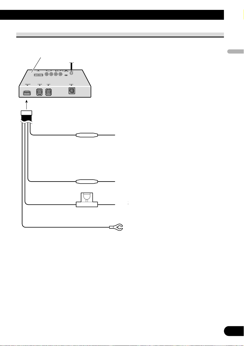
Connecting the Power Cord
useresisto
useresisto
hold
(
)
Black
(g
d)
ovehicle
(
l)
body
Hid
it
Y
ello
w
o
terminal
pplied
withpowe
re
gardless
of
igniti
switch
positi
o
lighting
switch
e-away un
F
F
Fuse
4 A
Red
r
r
er
When using this product in STAND ALONE
mode, connect this cord to electric terminal
controlled by ignition switch (12 V DC) ON/OFF.
When using this product in IP BUS mode,
do not connect this cord.
Orange/white
T
ello
T
terminal.
alwayssu
on
on.
roun
T
meta
.
10
Installation
Note:
• Before making a final installation of the unit,
temporarily connect the wiring to confirm that the
connections are correct and the system works
properly.
• Use only the parts included with the unit to
ensure proper installation. The use of unauthorized parts can cause malfunctions.
• Consult with your nearest dealer if installation
requires the drilling of holes or other modifications of the vehicle.
• Install the unit where it does not get in the driver’s way and cannot injure the passenger if there
is a sudden stop, like an emergency stop.
• Do not place the display (sold separately) in a
position where it will impede the driver’s visibility or affect the operation of your vehicle’s air
bags.
• The semiconductor laser will be damaged if it
overheats, so don’t install the unit anywhere hot
— for instance, near a heater outlet.
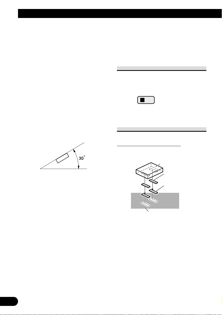
• If installation angle exceeds 30° from horizontal,
the unit might not give its optimum performance.
• When installing, to ensure proper heat dispersal
when using this unit, make sure you leave ample
space behind the rear panel and wrap any loose
cables so they are not blocking the vents.
• When mounting the hide-away unit, make sure
none of the leads are trapped between the hideaway unit and the surrounding metalwork or fittings.
• Do not mount the hide-away unit near the heater
outlet, where it would be affected by heat, or near
the doors, where rainwater might splash onto it.
• Before drilling any mounting holes always check
behind where you want to drill the holes. Do not
drill into the gas line, brake line, electrical wiring
or other important parts.
• If the hide-away unit is installed in the passenger
compartment, anchor it securely so it does not
break free while the car is moving, and cause
injury or an accident.
• If the hide-away unit is installed under a front
seat, make sure it does not obstruct seat movement. Route all leads and cords carefully around
the sliding mechanism so they do not get caught
or pinched in the mechanism and cause a short
circuit.
MODE Switch Setting
Before installing, use a pen tip or other thin,
pointed instrument to set the MODE Switch to
the appropriate position for the component
you are using it with.
Installing the hide-away unit
Mounting with Velcro Tape
Thoroughly wipe off the surface
before affixing the velcro tape.
STAND ALONE
IP BUS
Hide-away unit
Velcro tape
(large) (hard)
Velcro tape
(large) (soft)
Car mat or chassis

11
English
Español
Português (B)
Français
Italiano
Nederlands
DIN Front/Rear-mount
This unit can be properly installed either from “Front” (conventional DIN Front-mount) or
“Rear” (DIN Rear-mount installation, utilizing threaded screw holes at the sides of unit
chassis). For details, refer to the following illustrated installation methods.
DIN Front-mount
Installation with the rubber bush
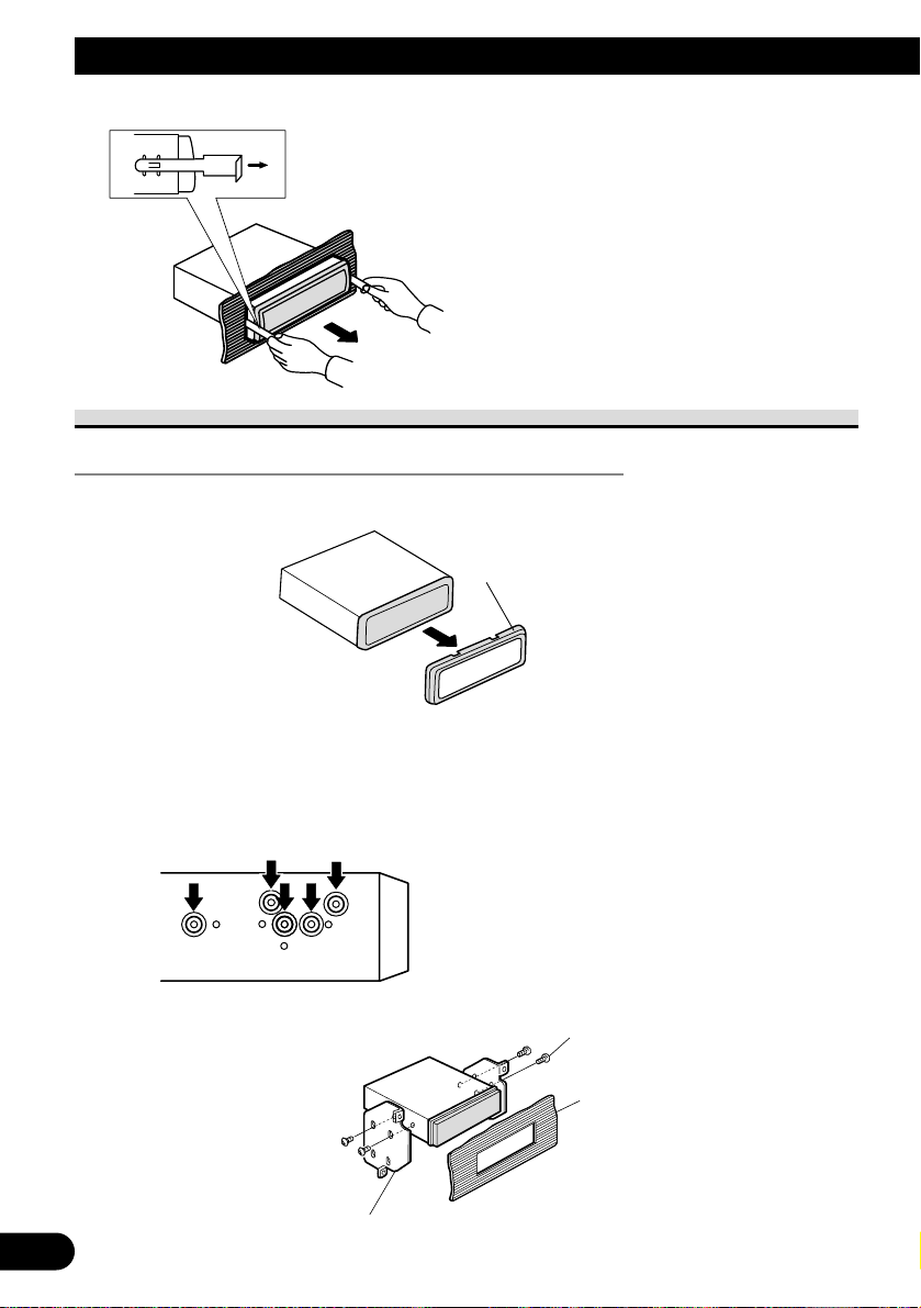
Removing the unit
To remove the frame, extend top and bottom of the frame outwards in order to unlock it.
(When reattaching the frame, point the side with a groove downwards and attach it.)
• It becomes easy to remove the frame if the front panel is released.
Holder
After inserting the holder into the dashboard, then select the appropriate tabs
according to the thickness of the dashboard material and bend them.
(Install as firmly as possible using the
d
bottom
tabs. To secure, bend
the
tabs
90
deg
)
ubbe
w
d
e
ashboar
topan
R
r
cre
rees.
Fram
Frame
12
Installation
DIN Rear-mount
Installation using the screw holes on the side of the unit
1. Remove the frame.
To remove the frame, extend top and bottom of the frame outwards in order to unlock it.
(When reattaching the frame, point the side with a groove downwards and attach it.)
• It becomes easy to remove the frame if the front panel is released.
2. Fastening the unit to the factory radio mounting bracket.
Select a position where the screw holes of the
bracket and the screw holes of the head unit
become aligned (are fitted), and tighten the
screws at 2 places on each side. Use either
truss screws (5
× 8 mm) or flush surface
screws (5 × 8 mm), depending on the shape of
the screw holes in the bracket.
Insert the supplied extraction keys into the
unit, as shown in the figure, until they
click into place. Keeping the keys pressed
against the sides of the unit, pull the unit
out.
Screw
Dashboard or Console
Factory radio mounting bracket
Frame
 Loading...