

Page 1
English
Español
Deutsch
Français
Italiano
Nederlands
XDV-P6
This product conforms to new cord colors.
Los colores de los cables de este producto se conforman con un nuevo código de colores.
Dieses Produkt entspricht den neuen kabelfarben.
Le code de couleur des câbles utilisé pour ce produit est
nouveau.
Questo prodotto è conforme ai nuovi codici colori.
De kleuren van de snoeren van dit toestel zijn gewijzigd.
INSTALLATION MANUAL
MANUEL D’INSTALLATION
Page 2
2
Contents
Connecting the Units ................................ 2
Connecting the system (1).................................. 4
Connecting the system (2).................................. 6
When Connecting the Head Unit ...................... 8
When Using a Display Connected Rear Video
Output.......................................................... 9
Connecting the Power Cord ............................ 10
Installation ................................................ 11
MODE Switch Setting...................................... 11
Installing the hide-away unit .......................... 11
DIN Front/Rear-mount .................................... 12
DIN Front-mount ............................................ 12
DIN Rear-mount .............................................. 13
Mounting with Brackets .................................. 14
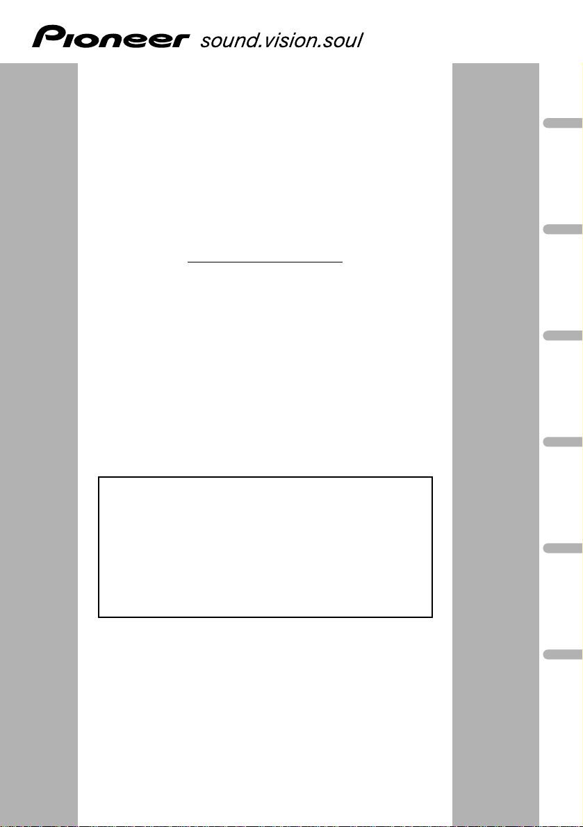
WARNING:
• To avoid the risk of accident and the
potential violation of applicable laws,
the front DVD or TV (sold separately)
feature should never be used while the
vehicle is being driven. Also, Rear
Displays should not be in a location
where it is a visible distraction to the
driver.
• In some countries or states the viewing
of images on a display inside a vehicle
even by persons other than the driver
may be illegal. Where such regulations
apply, they must be obeyed and this
unit’s DVD features should not be used.
CAUTION:
• PIONEER does not recommend that
you install or service your display (sold
separately) yourself. Installing or servicing the product may expose you to risk
of electric shock or other hazards. Refer
all installation and servicing of your display to authorized Pioneer service personnel.
• Secure all wiring with cable clamps or
electrical tape. Do not allow any bare
wiring to remain exposed.
• Do not drill a hole into the engine compartment to connect the yellow lead of
the unit to the vehicle battery. Engine
vibration may eventually cause the insulation to fail at the point where the wire
passes from the passenger compartment
into the engine compartment. Take
extra care in securing the wire at this
point.
• It is extremely dangerous to allow the
display (sold separately) lead to become
wound around the steering column or
gearshift. Be sure to install the display
in such a way that it will not obstruct
driving.
• Make sure that wires will not interfere
with moving parts of the vehicle, such as
the gearshift, parking brake or seat sliding mechanism.
• Do not shorten any leads. If you do, the
protection circuit may fail to work
properly.
• Do not install the display (sold separately) where it may (i) obstruct the
driver’s vision, (ii) impair the performance of any of the vehicle’s
operating systems or safety features,
including air bags, hazard lamp buttons or (iii) impair the driver’s ability to safely operate the vehicle.
Connecting the Units
Page 3

English
Español
Deutsch
Français
Italiano
Nederlands
3
Note:
• This unit is for vehicles with a 12-volt battery and
negative grounding. Before installing it in a recreational vehicle, truck, or bus, check the battery
voltage.
• To avoid shorts in the electrical system, be sure to
disconnect the ≠ battery cable before beginning
installation.
• Refer to the owner’s manual for details on
connecting the power amp and other units, then
make connections correctly.
• Secure the wiring with cable clamps or adhesive
tape. To protect the wiring, wrap adhesive tape
around them where they lie against metal parts.
• Route and secure all wiring so it cannot touch any
moving parts, such as the gear shift, handbrake
and seat rails. Do not route wiring in places that
get hot, such as near the heater outlet. If the insulation of the wiring melts or gets torn, there is a
danger of the wiring short-circuiting to the vehicle
body.
• Don’t pass the yellow lead through a hole into the
engine compartment to connect to the battery.
This will damage the lead insulation and cause a
very dangerous short.
• Do not shorten any leads. If you do, the protection
circuit may fail to work when it should.
• Never feed power to other equipment by cutting
the insulation of the power supply lead of the unit
and tapping into the lead. The current capacity of
the lead will be exceeded, causing overheating.
• When replacing the fuse, be sure to only use a
fuse of the rating prescribed on the fuse holder.
• To avoid a short-circuit, cover the disconnected
lead with insulating tape. Insulate the unused
speaker leads without fail. There is a possibility of
a short-circuit if the leads are not insulated.
• To prevent incorrect connection, the input side of
the IP-BUS connector is blue, and the output side
is black. Connect the connectors of the same colors correctly.
• This unit cannot be installed in a vehicle that
does not have an ACC (accessory) position on
the ignition switch.
• The black lead is ground. Please ground this lead
separately from the ground of high-current products such as power amps.
If you ground the products together and the
ground becomes detached, there is a risk of damage to the products or fire.
No ACC positionACC position
• Cords for this product and those for other products may be different colors even if they have
the same function. When connecting this product to another product, refer to the supplied
manuals of both products and connect cords
that have the same function.
C
C
A
O
F
N
F
O
S
T
A
R
T
O
F
N
F
O
S
T
A
R
T
Page 4

4
Connecting the Units
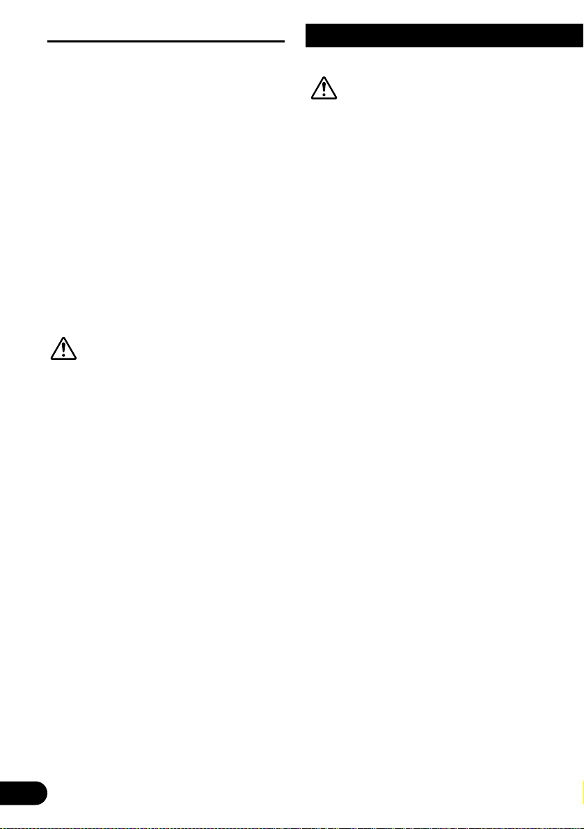
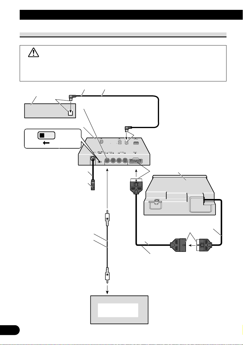
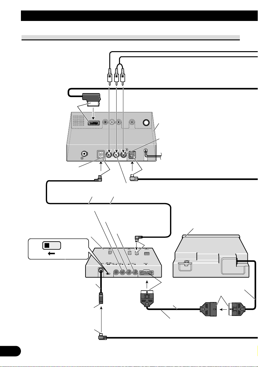
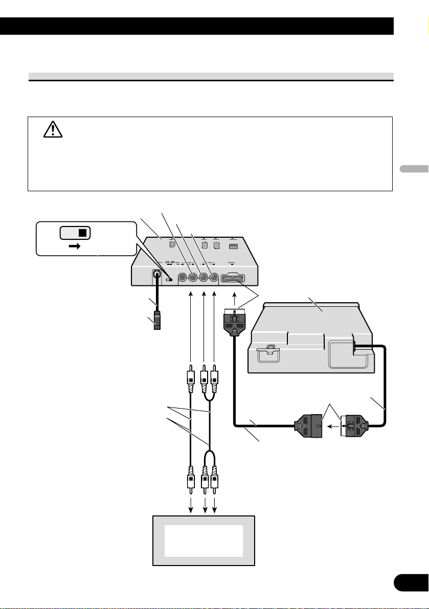
Connecting the system (1)
Yellow
Navigation system (AVIC-X1BT)
hide-away unit (sold separately)
When installing
the Hide-away unit
in the boot, etc.,
the extension cable
(e.g. CD-SC300E)
(sold separately)
is required.
Yellow
IP-BUS cable (supplied)
6 m
Black
STAND ALONE
IP BUS
White (audio output (Left))
Red (audio output (Right))
Yellow (rear video output)
Hide-away unit
This product
25 pin cable (supplied)
Depending on where you install,
this cable is not used.
Black
Black
20 cm
2.7 m
9 cm
Black
Black
Blue Blue
White
Red
Page 5
English
Español
Deutsch
Français
Italiano
Nederlands
5
White
3 m
16:9 Rear Seat Entertainment Display
(AVD-W6200) (sold separately)
Hide-away unit
(supplied with AVD-W6200)
VIDEO1 INPUT
VIDEO1 RCA audio input
(white, red)
VIDEO1 RCA video input
(yellow)
Yellow
3 m
30-pin cable
Navigation system (AVIC-X1BT) display unit
(sold separately)
AV-BUS cable (supplied)
6 m
RCA cable (supplied)
6 m
Page 6

6
Connecting the Units
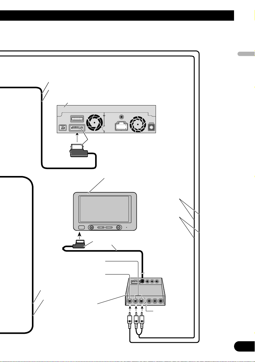
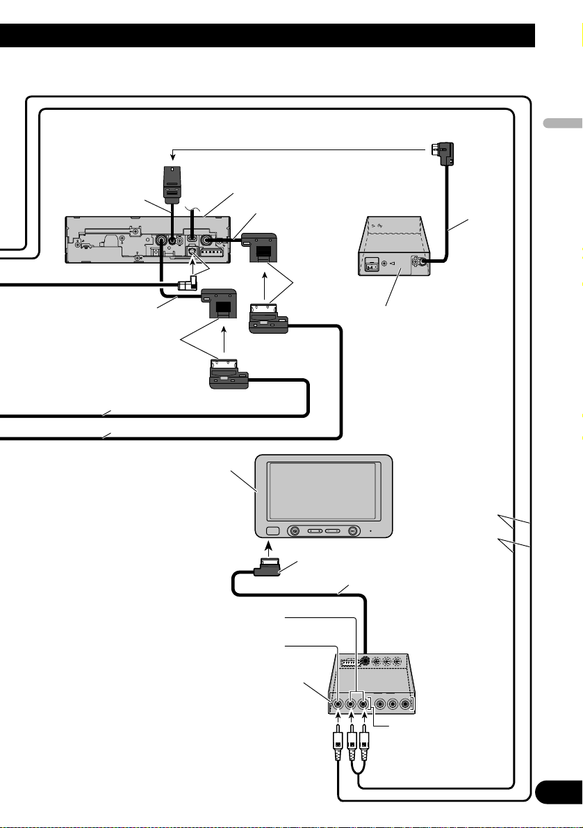
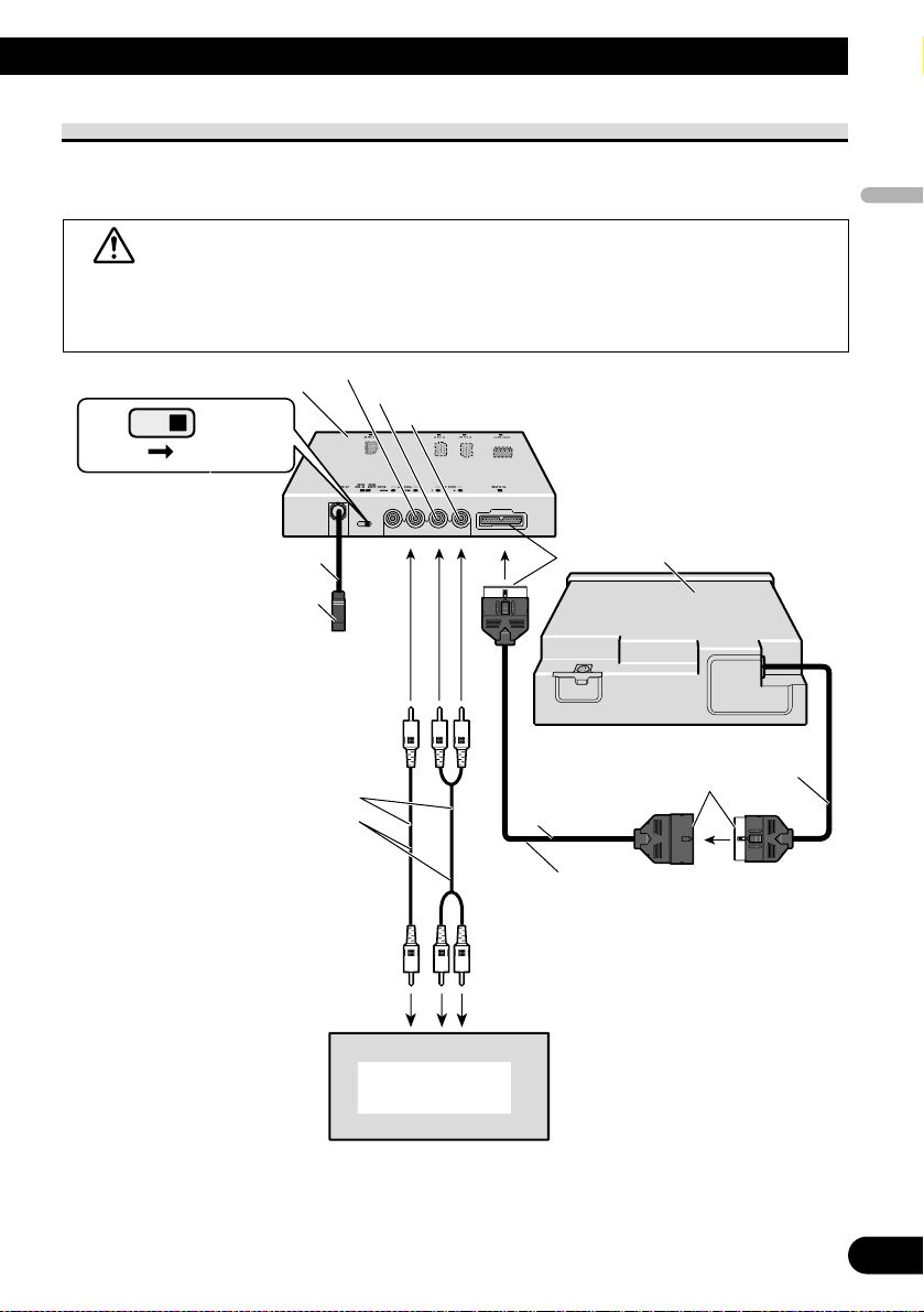
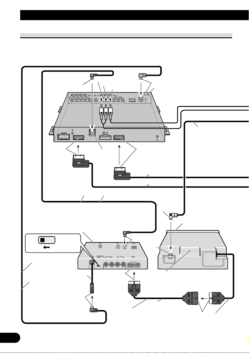
Connecting the system (2)
Blue
Violet
6 m
6 m
Hide-away unit (supplied with
AVH-P7800DVD)
Optical cable
(sold separately)
Blue
IP-BUS cable (supplied)
6 m
STAND ALONE
IP BUS
Hide-away unit
9 cm
Black
AV-BUS cable (supplied)
6 m
Blue
Blue
Red
White
Yellow
Black
Black
This product
25 pin cable (supplied)
Depending on where you install,
this cable is not used.
Black
Black
2.7 m
Black
20 cm
When using an optical cable, insert a clamp
(supplied with the optical cable) in the hole
and secure the cable.
Page 7
7
English
Español
Deutsch
Français
Italiano
Nederlands
Violet
Blue
30-pin cable (supplied with AVH-P7800DVD)
30-pin cable (supplied with AVH-P7800DVD)
40 cm
15 cm
40 cm
1 m
Multi-CD control DSP High Power DVD-A/DVD-V/
VCD/CD/MP3/WMA/AAC/DivX/JPEG Player
with RDS Tuner (AVH-P7800DVD) (sold separately)
Power supply box
(supplied with AVH-P7800DVD)
Blue
White
3 m
16:9 Rear Seat Entertainment Display
(AVD-W6200) (sold separately)
Hide-away unit (supplied with AVD-W6200)
VIDEO1 INPUT
VIDEO1 RCA audio input
(white, red)
VIDEO1 RCA video input
(yellow)
RCA cable (supplied)
6 m
Page 8
8
Connecting the Units
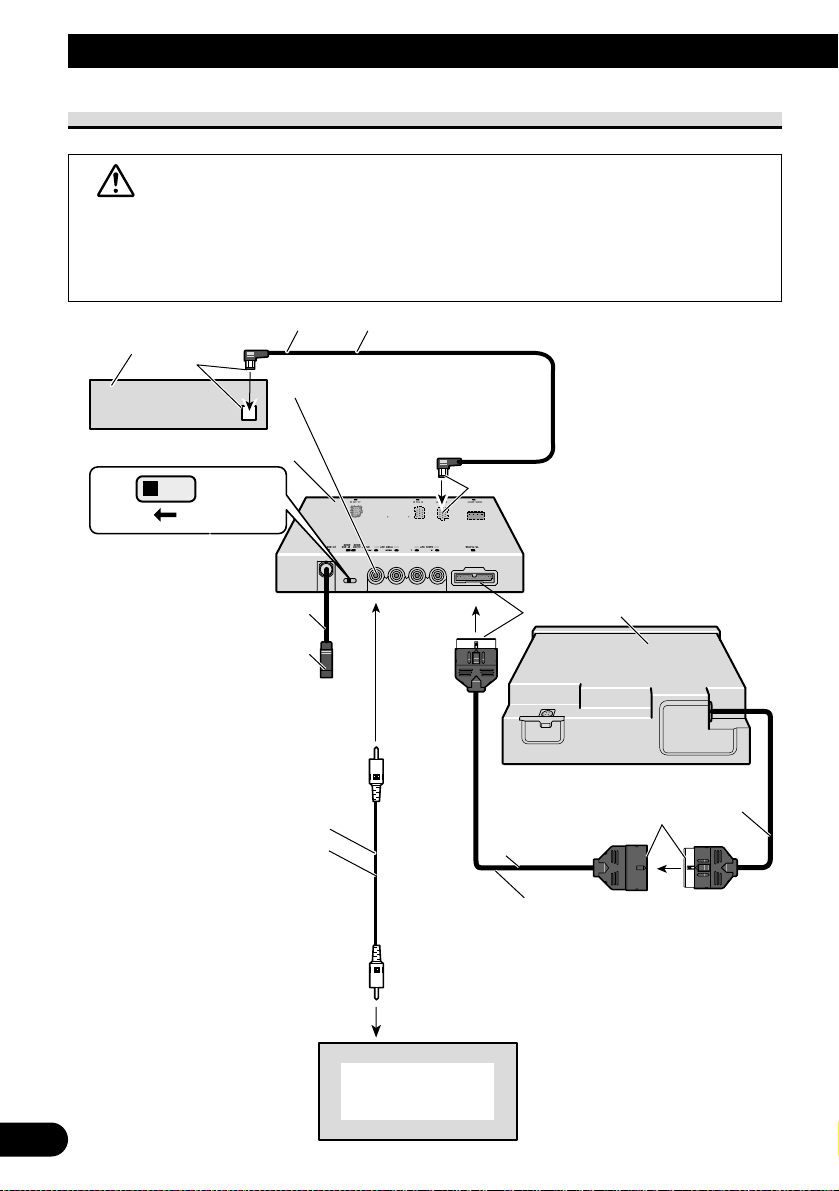
When Connecting the Head Unit
WARNING
• NEVER install the display in a location that enables the Driver to watch the DVD or
Video CD while Driving.
• NEVER connect audio output (AUDIO OUT) to sold separately power amp.
(sold
ly)
Blue
IP-BUS cable (supplied)
6 m
Display
with
CA
input
j
s
CA
cable
(
supplied)
o
v
o
input
)
6 m
Head Unit
separate
Yellow (front video output
Hide-away unit
IP BUS
STAND ALONE
Black
This product
Black
20 cm
Not used.
R
T
9 cm
ide
Black
2.7 m
25 pin cable (supplied)
Depending on where you install,
this cable is not used.
R
ack
Page 9
9
English
Español
Deutsch
Français
Italiano
Nederlands
When Using a Display Connected Rear Video Output
This product’s rear video output is for connection of a display to enable passengers in the
rear seats to watch the DVD or Video CD.
WARNING
• NEVER install the display in a location that enables the Driver to watch the DVD or
Video CD while Driving.
• NEVER connect audio output (AUDIO OUT) to sold separately power amp.
E
Display
with
CA
input
jacks
CA
cable
(
pplied)
dio
inputs
o
video
input
White
(audio
output
(Left))
d
(
o
output
)
)
H
t
6 m
Yellow (rear video output
Re
audi
(Right)
IP BUS
ide-away uni
STAND ALON
9 cm
Not used.
R
T
Black
This product
su
2.7 m
25 pin cable (supplied)
Depending on where you install,
this cable is not used.
Toau
Black
20 cm
R
Page 10
10
Connecting the Units
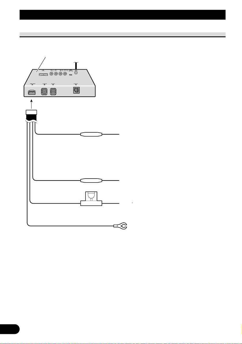
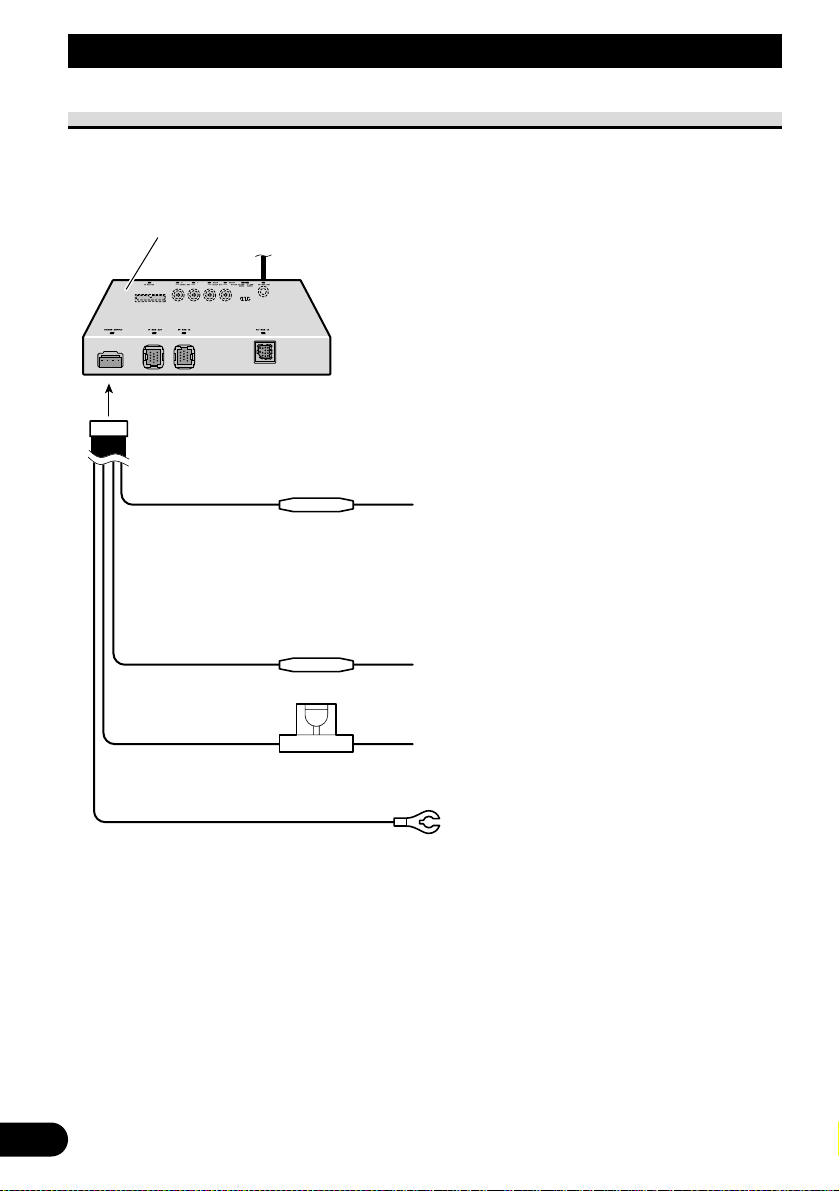
Connecting the Power Cord
useresisto
useresisto
hold
(
)
Black
(g
d)
ovehicle
(
l)
body
Hid
it
Y
ello
w
o
terminal
pplied
withpowe
re
gardless
of
igniti
switch
positi
o
lighting
switch
e-away un
F
F
Red
r
r
When using this product in STAND ALONE
mode, connect this cord to electric terminal
controlled by ignition switch (12 V DC) ON/OFF.
When using this product in IP BUS mode,
do not connect this cord.
Orange/white
T
terminal.
ello
Fuse
er
4 A
T
T
roun
meta
alwayssu
on
on.
.
Page 11
Installation
11
English
Español
Deutsch
Français
Italiano
Nederlands
Note:
• Before making a final installation of the unit,
temporarily connect the wiring to confirm that the
connections are correct and the system works
properly.
• Use only the parts included with the unit to
ensure proper installation. The use of unauthorized parts can cause malfunctions.
• Consult with your nearest dealer if installation
requires the drilling of holes or other modifications of the vehicle.
• Install the unit where it does not get in the driver’s way and cannot injure the passenger if there
is a sudden stop, like an emergency stop.
• Do not place the display (sold separately) in a
position where it will impede the driver’s visibility or affect the operation of your vehicle’s air
bags.
• The semiconductor laser will be damaged if it
overheats, so don’t install the unit anywhere hot
— for instance, near a heater outlet.
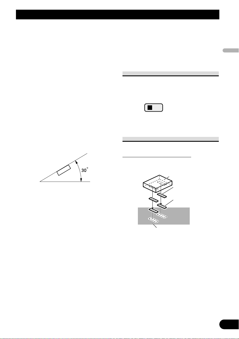
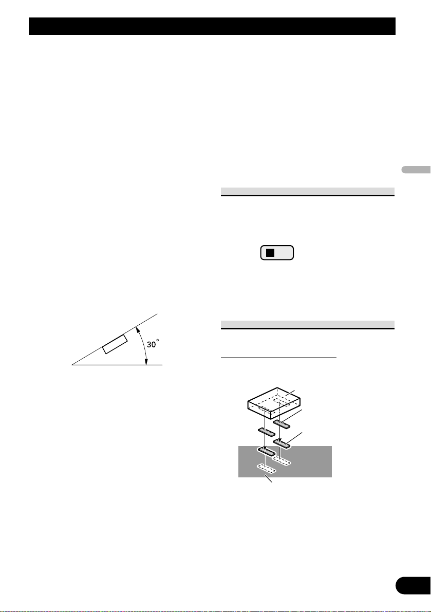
• If installation angle exceeds 30° from horizontal,
the unit might not give its optimum performance.
• When mounting the hide-away unit, make sure
none of the leads are trapped between the hideaway unit and the surrounding metalwork or fittings.
• Do not mount the hide-away unit near the heater
outlet, where it would be affected by heat, or near
the doors, where rainwater might splash onto it.
• Before drilling any mounting holes always check
behind where you want to drill the holes. Do not
drill into the gas line, brake line, electrical wiring
or other important parts.
• If the hide-away unit is installed in the passenger
compartment, anchor it securely so it does not
break free while the car is moving, and cause
injury or an accident.
• If the hide-away unit is installed under a front
seat, make sure it does not obstruct seat movement. Route all leads and cords carefully around
the sliding mechanism so they do not get caught
or pinched in the mechanism and cause a short
circuit.
MODE Switch Setting
Before installing, use a pen tip or other thin,
pointed instrument to set the MODE Switch to
the appropriate position for the component
you are using it with.
Installing the hide-away unit
Mounting with Velcro Tape
Thoroughly wipe off the surface
before affixing the velcro tape.
STAND ALONE
IP BUS
Hide-away unit
Velcro tape
(large) (hard)
Velcro tape
(large) (soft)
Car mat or chassis
Page 12
12
Installation
DIN Front/Rear-mount
This unit can be properly installed either from “Front” (conventional DIN Front-mount) or
“Rear” (DIN Rear-mount installation, utilizing threaded screw holes at the sides of unit
chassis). For details, refer to the following illustrated installation methods.
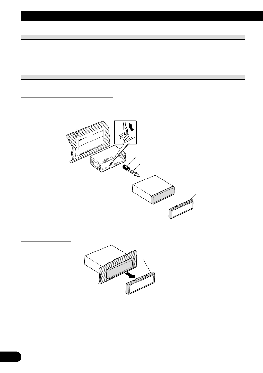
DIN Front-mount
Installation with the rubber bush
Removing the unit
To remove the frame, extend top and bottom of the frame outwards in order to unlock it.
(When reattaching the frame, point the side with a groove downwards and attach it.)
• It becomes easy to remove the frame if the front panel is released.
Holder
After inserting the holder into the dashboard, then select the appropriate tabs
according to the thickness of the dashboard material and bend them.
(Install as firmly as possible using the
d
bottom
tabs. To secure, bend
the
tabs
90
deg
)
ubbe
w
d
e
ashboar
topan
R
cre
r
rees.
Fram
Frame
Page 13
13
English
Español
Deutsch
Français
Italiano
Nederlands
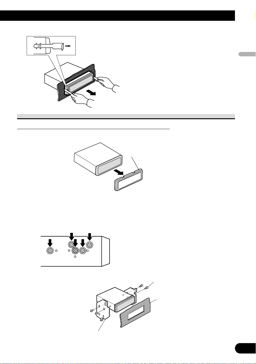
DIN Rear-mount
Installation using the screw holes on the side of the unit
1. Remove the frame.
To remove the frame, extend top and bottom of the frame outwards in order to unlock it.
(When reattaching the frame, point the side with a groove downwards and attach it.)
• It becomes easy to remove the frame if the front panel is released.
2. Fastening the unit to the factory radio mounting bracket.
Select a position where the screw holes of the
bracket and the screw holes of the head unit
become aligned (are fitted), and tighten the
screws at 2 places on each side. Use either
truss screws (5
× 8 mm) or flush surface
screws (5 × 8 mm), depending on the shape of
the screw holes in the bracket.
Insert the supplied extraction keys into the
unit, as shown in the figure, until they
click into place. Keeping the keys pressed
against the sides of the unit, pull the unit
out.
Screw
Dashboard or Console
Factory radio mounting
bracket
Frame
Page 14
14
Installation
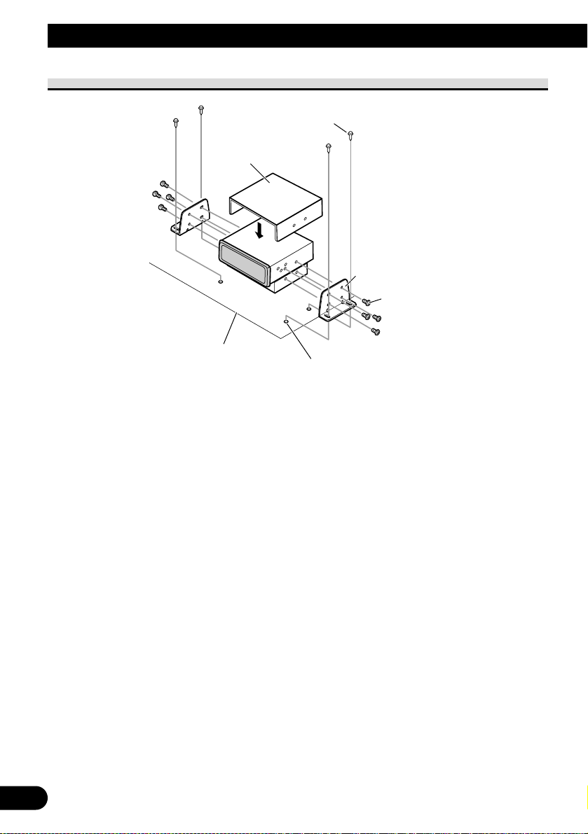
Mounting with Brackets
Car mat or chassis
Drill 4 to 4.5 mm diameter holes.
Bracket
Truss screw (5 × 8 mm)
Tapping screw (6 × 16 mm)
Cover
Page 15

English
Español
Deutsch
Français
Italiano
Nederlands
15
Page 16
2
Contenido
Conexión de las unidades ........................ 2
Conexión al sistema (1) .................................... 4
Conexión al sistema (2) .................................... 6
Cuando conecte la unidad principal .................. 8
Cuando utilice un presentación visual
conectado a la salida de vídeo trasera ........ 9
Conexión del cable de alimentación ................ 10
Instalación ................................................ 11
Ajuste del interruptor MODE .......................... 11
Instalación de la unidad oculta-alejada .......... 11
Montaje delantero/trasero DIN ........................ 12
Montaje delantero DIN .................................... 12
Montaje trasero DIN ........................................ 13
Montaje con ménsulas .................................... 14
ADVERTENCIA:
• Para evitar el riesgo de accidente y la
violación potencial de las leyes aplicables, no se debe utilizar nunca la función
de DVD o TV delantero (vendido separadamente) mientras se esté conduciendo el vehículo. Igualmente, no se deben
posicionar las pantallas traseras en un
lugar donde puedan distraer la visión
del conductor.
• En algunos países o estados, puede que
la visualización de las imágenes en una
pantalla dentro del vehículo sea ilegal,
aún por los pasajeros. Cuando existan
tales reglamentos, se debe obedecerlos y
no se debe utilizar las funciones de DVD
de esta unidad.
PRECAUCIÓN:
• PIONEER no recomienda que sea usted
mismo quien instale o revise su pantalla
(vendido separadamente).
La instalación o revisión del producto
puede exponerle a descargas eléctricas u
otros peligros. Solicite que todos los
trabajos de instalación y revisión de su
pantalla los realice el personal de
servicio Pioneer autorizado.
• Asegure todo el cableado con
abrazaderas de cables o cinta para usos
eléctricos. No permita que el cableado
pelado permanezca expuesto.
•
No taladre un agujero en el
compartimiento del motor para conectar
el cable amarillo de la unidad a la batería
del vehículo. La vibración del motor
podría estropear el aislamiento en el
punto por donde el cable pasa del
compartimiento de los pasajeros al
compartimiento del motor. Tenga mucho
cuidado para mantener el buen estado
del cable en lo relativo a este punto.
• Es peligrosísimo dejar que el cable de la
pantalla (vendido separadamente) se
enrolle en la base del volante o en la
palanca de cambios. Asegúrese de
instalar la pantalla de forma que ésta no
sea un obstáculo para la conducción.
• Asegúrese de que los cables no interfieran
con partes móviles del vehículo tales
como la palanca de cambio, el freno de
mano o el mecanismo de deslizamiento de
los asientos.
• No acorte ningún cable. Si lo hace, el
circuito de protección tal vez no
funcione correctamente.
• No instale la pantalla (vendido
separadamente) donde pueda (i)
obstruir la visión del conductor, (ii)
perjudicar el rendimiento de cualquier
sistema de operación o funciones de
seguridad del vehículo, incluyendo las
bolsas de aire, botón de la luz de
emergencia o (iii) perjudicar la
habilidad del conductor para operar el
vehículo con seguridad.
Conexión de las unidades
Page 17
English
Español
Deutsch
Français
Italiano
Nederlands
Español
Deutsch
Français
Italiano
Nederlands
3
Nota:
• Esta unidad es para vehículos con batería de 12
voltios y con conexión a tierra. Antes de instalar
la unidad en un vehículo recreativo, camioneta, o
autobús, revise el voltaje de la batería.
• Para evitar cortocircuitos en el sistema eléctrico,
asegúrese de desconectar el cable de la batería ≠
antes de comenzar con la instalación.
• Consulte con el manual del usuario para los
detalles sobre la conexión de la alimentación de
amperios y de otras unidades, luego haga las
conexiones correctamente.
• Asegure el cableado con abrazaderas de cables o
con cinta adhesiva. Para proteger el cableado,
envuélvalo con cinta adhesiva donde éstos se
apoyan sobre las piezas de metal.
• Coloque y asegure todo el cableado de tal manera
que no toque las piezas en movimiento, tal como
la palanca de cambio de velocidades, el freno de
mano, y los pasamanos de los asientos. No
coloque el cableado en lugares que se calientan,
tal como cerca de la salida de un calefactor. Si el
material aislante del cableado se derritiera o se
gastara, habrá el peligro de un cortocircuito del
cableado a la carrocería del vehículo.
• No pase el conductor amarillo a través de un orificio en el compartimiento del motor para conectar
a la batería. Esto dañará el material aislante del
conductor y causará un cortocircuito peligroso.
• No acorte ningún conductor. Si lo hiciera, la protección del circuito podría fallar al funcionar
cuando debería.
• Nunca alimente energía a otros equipos cortando
el aislamiento del conductor de alimentación provista de la unidad y haciendo un empalme con el
conductor. La capacidad de corriente del conductor se excederá, causando el recalentamiento.
• Cuando reemplace el fusible, asegúrese de utilizar
solamente un fusible del ratio especificado en el
portafusible.
• Para evitar cortocircuitos, cubra o conductor
desconectado con cinta aislada. Aísle los conductores de altavoz no usados sin falta. Hay la posibilidad de cortocircuito si no se aíslan los conductores.
• Para evitar la conexión incorrecta, el lado de entrada del conector IP-BUS es azul, y el lado de
salida es negro. Conecte los conectores del mismo
color correctamente.
• Esta unidad no se puede instalar en un
vehículo que no dispone de la posición ACC
(accesorio) en el interruptor de encendido.
• El conductor negro es la masa. Conecte a masa
este conductor separadamente desde la masa de
los productos de alta corriente tal como los amplificadores de potencia.
Si conecta juntos a masa los productos y la masa
se desconecta, se crea el riesgo de daños a los productos o de incendios.
No en la posición ACCPosición ACC
• Los cables para este producto y aquéllas para
otros productos pueden ser de colores diferentes
aun si tienen la misma función. Cuando se conecta este producto a otro, refiérase a los manuales
de ambos productos y conecte los cables que
tienen la misma función.
C
C
A
O
F
N
F
O
S
T
A
R
T
O
F
N
F
O
S
T
A
R
T
Page 18
4
Conexión de las unidades
Conexión al sistema (1)
Amarillo
Unidad oculta-alejada (vendida separadamente)
de sistema de navegación (AVIC-X1BT)
Cuando instale la
unidad oculta-alejada
en el portaequipajes,
etc., se requiere un
cable de extensión
(por ejemplo,
CD-SC300E)
(vendido
separadamente).
Amarillo
Cable IP-BUS (suministrado)
6 m
Negro
STAND ALONE
IP BUS
Blanco (salida de áudio
(canal izquierdo))
Rojo (salida de áudio
(canal derecho))
Amarillo (salida de vídeo trasera)
Unidad oculta-alejada
Este producto
Cable de 25 clavijas (suministrado)
Dependiendo en donde instale, no se
utiliza este cable.
Negro
Negro
20 cm
2,7 m
9 cm
Negro
Negro
Azul Azul
Blanco
Rojo
Page 19

English
Español
Deutsch
Français
Italiano
Nederlands
5
White
3 m
Pantalla de entretenimiento de 16:9 para
asiento trasero (AVD-W6200)
(vendida separadamente)
Unidad oculta-alejada
(suministrada con AVD-W6200)
VIDEO1 INPUT
Salida de audio VIDEO1 RCA
(blanco, rojo)
Entrada de vídeo VIDEO1 RCA
(amarillo)
Yellow
3 m
Cable de 30 clavijas
Unidad de visualización (vendida separadamente)
de sistema de navegación (AVIC-X1BT)
Cable AV-BUS (suministrado)
6 m
Cable RCA (suministrado)
6 m
Page 20
6
Conexión de las unidades
Conexión al sistema (2)
Azul
Violeta
6 m
6 m
Unidad oculta-alejada
(suministrada con AVH-P7800DVD)
Cable óptico
(vendido separadamente)
Azul
Cable IP-BUS (suministrado)
6 m
STAND ALONE
IP BUS
Unidad oculta-alejada
9 cm
Negro
Cable AV-BUS
(suministrado)
6 m
Azul
Azul
Rojo
Blanco
Amarillo
Negro
Negro
This product
Cable de 25 clavijas (suministrado)
Dependiendo en donde instale, no se
utiliza este cable.
Negro
Negro
2,7 m
Negro
20 cm
Cuando utilice un cable óptico, inserte la
abrazadera (suministrada con el cable
óptico) en el orificio y fije el cable.
Page 21

English
Español
Deutsch
Français
Italiano
Nederlands
7
Violeta
Azul
Cable de 30 clavijas (suministrada con AVH-P7800DVD)
Cable de 30 clavijas (suministrada con AVH-P7800DVD)
40 cm
15 cm
40 cm
1 m
Reproductor de DVD-A/DVD-V/VCD/CD/MP3/WMA/
AAC/DivX/JPEG de alta potencia con DSP, control de
Multi-CD y sintonizador (AVH-P7800DVD) (vendido
separadamente)
Caja de suministro de energía
(suministrada con AVH-P7800DVD)
Azul
Blanco
3 m
Pantalla de entretenimiento de 16:9 para
asiento trasero (AVD-W6200)
(vendida separadamente)
Unidad oculta-alejada (suministrada con AVD-W6200)
VIDEO1 INPUT
Salida de audio VIDEO1 RCA
(blanco, rojo)
Entrada de vídeo VIDEO1 RCA
(amarillo)
Cable RCA (suministrado)
6 m
Page 22
8
Conexión de las unidades
Cuando conecte la unidad principal
ADVERTENCIA
• NUNCA instale el presentación visual en un lugar que permita el motorista ver el DVD
o Video CD mientras conduce el automóvil.
• NUNCA conecte la salida de audio (AUDIO OUT) al amplificador de potencia vendido
separadamente.
Unidad principal
(vendido separadamente)
Azul
Unidad oculta-alejada
IP BUS
STAND ALONE
Cable RCA (suministrado)
Cable IP-BUS (suministrado)6 m
Amarillo (salida de vídeo delantera)
9 cm
No se usa.
6 m
Negro
2,7 m
Negro
Este producto
Negro
20 cm
Cable de 25 clavijas (suministrado)
Dependiendo en donde instale, no se
utiliza este cable.
A la entrada de vídeo
Presentación visual
con tomas de entrada
RCA
Page 23
English
Español
Deutsch
Français
Italiano
Nederlands
9
Cuando utilice un presentación visual conectado a la salida
de vídeo trasera
La salida de vídeo trasera de este producto es para la conexión de un presentación visual
para permitir que los pasajeros en los asientos traseros puedan ver el DVD o Video CD.
ADVERTENCIA
• NUNCA instale el presentación visual en un lugar que permita el motorista ver el DVD
o Video CD mientras conduce el automóvil.
• NUNCA conecte la salida de audio (AUDIO OUT) al amplificador de potencia vendido
separadamente.
IP BUS
Unidad oculta-alejada
STAND ALONE
9 cm
No se usa.
Cable RCA
(suministrado)
Amarillo (salida de vídeo trasera)
Blanco (salida de áudio (canal izquierdo))
Rojo (salida de áudio (canal derecho))
Negro
6 m
2,7 m
Cable de 25 clavijas (suministrado)
Dependiendo en donde instale, no se
utiliza este cable.
A las entradas de audioA la entrada de vídeo
Este producto
Negro
20 cm
Presentación visual
con tomas de entrada
RCA
Page 24
10
Conexión de las unidades
Conexión del cable de alimentación
Unidad oculta-alejada
Resistencia de fusible
Rojo
Cuando utilice este producto en el modo
STAND ALONE, conecte este cable al
terminal eléctrico controlado por el interruptor
de encendido del vehículo (12 V de CC) ON/OFF.
Cuando utilice este producto en el modo IP BUS,
no conecte este cable.
Resistencia de fusible
Resistencia de fusible (4 A)
Anaranjado/blanco
Al terminal de interruptor de
iluminación.
Amarillo
Al terminal con suministro constante
de electricidad, independientemente de
la posición del interruptor de encendido.
Negro (masa)
A la carrocería del veículo (parte metálica).
Page 25
Instalación
11
English
Español
Deutsch
Français
Italiano
Nederlands
Nota:
• Antes de finalmente instalar la unidad, conecte el
cableado temporalmente y compruebe que las
conexiones están correctas e que el sistema funciona debidamente.
• Utilice sólo las piezas que se incluyen con esta
unidad para asegurar la instalación adecuada. El
uso de piezas no autorizadas podría causar fallos
de funcionamiento.
• Consulte con su distribuidor si la instalación
requiere del taladro de orificios u otras modificaciones del vehículo.
• Instale la unidad donde no alcance el espacio del
conductor, y donde no pueda dañar a los
pasajeros si sucediera un paro repentino, como
una detención de emergencia.
• No coloque el monitor (vendido separadamente)
en una posición en donde obstruya la visibilidad
del conductor o afecte la operación de los sacos
inflables del vehículo.
• El semiconductor láser se dañará si se sobrecalienta, por eso no instale la unidad en un lugar
caliente – por ejemplo, cerca de la salida de un
calefactor.
• Si el ángulo de la instalación excede los 30° del
lado horizontal, la unidad podría no brindar su
óptimo funcionamiento.
• Cuando monte la unidad oculta-alejada,
asegúrese de que ninguno de los conductores
esté atrapado entre la unidad oculta-alejada y los
metales o herrajes alrededor.
• No monte la unidad oculta-alejada cerca de la
salida del calentador, donde podría ser afectada
por el calor, o cerca de las puertas, donde podría
sufrir salpicadura del agua de lluvia.
• Antes de taladrar cualquier orificio de montaje
siempre compruebe lo que hay detrás en donde
desea taladrar los orificios. No taladre en la línea
de combustible, cableado eléctrico u otras partes
importantes.
• Si se instala la unidad oculta-alejada en el compartimiento de pasajeros, ánclela seguramente de
modo que no se suelte mientras el coche esté en
movimiento, lo que podría causar lesiones o
accidentes.
• Si se instala la unidad oculta-alejada bajo un
asiento delantero, asegúrese de que no obstruya
el movimiento del asiento. Encamine cuidadosamente los hilos y cables alrededor del mecanismo deslizante, de modo que no queden agarrados
o apretados en el mecanismo, lo que podría
causar un corto-circuito.
Ajuste del interruptor MODE
Antes de instalar, utilice la punta de un bolí-
grafo u otro objeto puntiagudo para ajustar el
interruptor MODE a la posición apropiada
para el componente que utilice.
Instalación de la unidad ocultaalejada
Montaje con cinta Velcro
Limpie completamente la superficie
antes de fijar la cinta Velcro.
Cinta Velcro
(grande) (dura)
Alfombra del
automóvil o chasis
Cinta Velcro
(grande) (blanda)
Unidad oculta-alejada
STAND ALONE
IP BUS
Page 26

12
Instalación
Montaje delantero/trasero DIN
Esta unidad quede instalarse correstamente de la “Delantera” (montaje delantero DIN
convenciona) o “Trasera” (montaje trasero DIN, utilizando los tornillos roscados en los
constados del chasis de la unidad). Para detalles, refiérase a los métodos de instalación
ilustrados abajo.
Montaje delantero DIN
Instalación con tope de goma
Quitado de la unidad
Para quitar el marco, extienda las partes superior e inferior del marco hacia fuera para desbloquearlo.
(Cuando recoloque el marco, apunte el lado con una ranura hacia abajo y fíjelo.)
• Se hace más fácil quitar el marco si se suelta el panel delantero.
Soporte
Después de insertar el soporte en la
Tablero de
instrumentos
182
53
tabla de mandos, luego seleccione las
orejetas apropiadas según el grosor del
material de la tabla de mandos y dóblelos.
(Instale lo más firme posible usando las
lengüe-tas superior e inferior. Para fijar,
doble las lengüetas 90 grados.)
Tope de goma
Tornillo
Marco
Marco
Page 27

English
Español
Deutsch
Français
Italiano
Nederlands
13
Montaje trasero DIN
Instalación usando los agujeros para tornillos ubicados en ambos costados de la unidad
1. Quite el marco.
Para quitar el marco, extienda las partes superior e inferior del marco hacia fuera para desbloquearlo.
(Cuando recoloque el marco, apunte el lado con una ranura hacia abajo y fíjelo.)
• Se hace más fácil quitar el marco si se suelta el panel delantero.
2. Fijación de la unidad a la ménsula de montaje existente.
Seleccione una posición en la que los orificios
para los tornillos del soporte y del de la
unidad principal queden alineados, y apriete
los tornillos en 2 lugares de un lado. Utilice ya
sea los tornillos de fijación (5
× 8 mm) o los
tornillos a paño (5 × 8 mm), dependiendo de
la forma de los orificios de tornillo en la mén-
sula.
Inserte las herramientas de extracción
suminis-tradas en la unidad, como se indica en la figura, hasta que se enganchen en
su positión.
Tire de la unidad mientras mantiene las
herramientas presionadas contra los lados
de la unidad.
Tornillo
Tablero de instrumentos o consola
Ménsula de montaje de
radio existente
Marco
Page 28

14
Instalación
Montaje con ménsulas
Alfombra del automóvil o chasis
Taladre orificios de 4 a 4,5 mm de diámetro.
Ménsula
Tornillo de refuerzo (5 × 8 mm)
Tornillo autoterrajante (6 × 16 mm)
Cubierta
Page 29

English
Español
Deutsch
Français
Italiano
Nederlands
15
Page 30

2
Inhalt
Anschließen der Einheiten ...................... 2
Anschluss des Systems (1) ................................ 4
Anschluss des Systems (2) ................................ 6
Bei Anschluss der Haupteinheit ........................ 8
Bei Gebrauch eines am hinteren Video-Ausgang
angeschlossenen Displays .............................. 9
Anschluss des Betriebsstromkabels ................ 10
Einbauverfahren ...................................... 11
Einstellung des Betriebsartenschalters
(MODE) .................................................... 11
Montage der Hideaway-Einheit ...................... 11
DIN-Befestigung von vorne/hinten ................ 12
DIN-Vordermontage ...................................... 12
DIN-Rückmontage .......................................... 13
Montage mit Halterungen ................................ 14
WARNUNG:
• Um die Gefahr eines Unfalls und eine
mögliche Verletzung geltender Gesetze
zu vermeiden, darf die Funktion für
DVD oder TV (im Handel erhältlich) im
Vorderraum niemals eingesetzt werden,
während das Fahrzeug in Bewegung ist.
Außerdem dürfen hintere Displays nicht
an einer Stelle angebracht werden, wo
sie eine sichtbare Ablenkung für den
Fahrer darstellen.
• In gewissen Ländern oder Staaten ist
das Betrachten von Bildern auf einem
Monitor in einem Fahrzeug untersagt,
auch durch Personen, die das Fahrzeug
nicht steuern. Wo derartige
Vorschriften gelten, müssen diese
eingehalten und die DVD-Funktionen
dieses Geräts dürfen nicht verwendet
werden.
VORSICHT:
• PIONEER rät nachdrücklich davon ab,
das Display (im Handel erhältlich)
eigenhändig einzubauen oder zu warten,
da hierbei die Möglichkeit elektrischer
Schläge und anderer Gefahren besteht.
Einbau und Wartung des Displays sind
deshalb dem autorisierten
Kundendienst-Fachpersonal zu
überlassen.
• Alle Kabel mit Kabelklemmen oder
Isolierband befestigen. Es dürfen keine
offenliegenden Drähte vorhanden sein.
• Kein Loch in den Motorraum bohren,
um das gelbe Kabel des Geräts an die
Fahrzeugbatterie anzuschließen: Die
Kabelisolierung kann am Übergangspunkt von Insassenraum zum
Motorraum durch die Vibration des
Motors beschädigt werden. Darauf
achten, das Kabel in diesem Bereich
besonders gut zu befestigen.
• Es ist äußerst gefährlich das Display (im
Handel erhältlich)-Kabel um die
Lenksäule oder den Gangschalthebel zu
wickeln. Beim Einbau unbedingt darauf
achten, dass das Display den Fahrer
nicht behindert.
• Vergewissern, dass die Kabel keine
beweglichen Teile des Fahrzeugs, wie
z.B. Gangschalthebel, Handbremse oder
Sitzverstellmechanismus, berühren.
• Kabel sollten grundsätzlich nicht
gekürzt werden. Andernfalls
funktioniert die Schutzschaltung
eventuell nicht ordnungsgemäß.
• Installieren Sie das Display (im Handel
erhältlich) nicht an einer Stelle, wo es (i)
das Blickfeld des Fahrers beschränken,
(ii) die Funktion irgendeines
Betriebssystems oder
Sicherheitsmerkmals des Fahrzeugs wie
Airbags und Warnlampentasten
beeinträchtigen oder (iii) den Fahrer bei
der sicheren Führung des Fahrzeugs
behindern könnte.
Anschließen der Einheiten
Page 31

English
Español
Deutsch
Français
Italiano
Nederlands
3
Hinweis:
• Dieses Gerät ist für Fahrzeuge mit 12-V-Batterie
und negativer Erdung (Minuspol an Masse)
ausgelegt. Prüfen Sie vor dem Einbau in ein
Wohnmobil, einen Lastwagen oder Bus die
Batteriespannung.
• Um Kurzschlüsse im elektrischen System zu
verhindern, ist unbedingt vor dem Einbau das
Minus-Batteriekabel ≠ abzutrennen.
• Nehmen Sie die Anschlüsse gemäß den
Anweisungen zum Anschluss des
Leistungsverstärkers und anderer Geräte in der
Bedienungsanleitung vor.
• Sichern Sie die Leitungen mit Kabelklemmen oder
Klebeband. Zum Schutz der Leitungen sollten sie
an den Stellen, wo sie Metallteile berühren, mit
Klebeband umwickelt werden.
• Verlegen und sichern Sie alle Leitungen so, dass
sie keine beweglichen Teile wie die
Gangschaltung, die Handbremse und Sitzschienen
berühren. Die Leitungen dürfen nicht an Stellen
entlanggeführt werden, die heiß werden, z.B. an
einer Heizungsauslassöffnung. Wenn die
Isolierung einer Leitung schmilzt oder aufreißt,
besteht die Gefahr eines Kurzschlusses mit der
Karosserie.
• Führen Sie die gelbe Leitung nicht durch ein Loch
in den Motorraum zum Anschluss an die Batterie.
Dadurch wird die Isolierung der Leitung
beschädigt, was zu einem sehr gefährlichen
Kurzschluss führen kann.
• Verkürzen Sie keine Leitungen. In diesem Fall
kann es vorkommen, dass die Schutzschaltung
nicht arbeitet, wenn sie gebraucht wird.
• Führen Sie niemals anderen Geräten Strom zu,
indem Sie die Isolierung der
Stromversorgungsleitung dieses Geräts
durchschneiden und davon Strom abzapfen.
Dadurch wird die Strombelastbarkeit der Leitung
überschritten, was zu Überhitzung führt.
• Als Ersatzsicherung darf nur eine solche mit dem
auf dem Sicherungshalter vorgeschriebenen
Sicherungswert verwendet werden.
• Um einen Kurzschluss zu vermeiden, umwickeln
Sie abgetrennte Leitungen mit Isolierband.
Unbenutzte Lautsprecherzuleitungen müssen
unbedingt isoliert werden. Wenn die Leitungen
nicht isoliert werden, besteht Kurzschlussgefahr.
• Um falsche Anschlüsse zu verhindern, ist die
Eingangsseite des IP-Bus-Steckverbinders blau
und die Ausgangsseite schwarz. Die
Steckverbinder derselben Farbe sind korrekt zu
verbinden.
• Dieses Gerät kann nicht in einem Fahrzeug
installiert werden, das keine ACC-Position
(Zubehörposition) am Zündschalter hat.
• Das schwarze Kabel ist das Erdungskabel. Dieses
Kabel ist getrennt von der Erde von HochstromGeräten, wie z.B. Leistungsverstärkern, zu erden.
Falls die Geräte zusammen geerdet werden, und
die Erdungsstelle abgetrennt wird, besteht die
Gefahr einer Beschädigung der Geräte oder eines
Brands.
Keine ACC-PositionACC-Position
• Kabel dieses Produkts und die anderer Produkte
können unterschiedliche Farben haben, auch
wenn sie die gleichen Funktionen haben. Beim
Anschluss dieses Produkts an ein anderes
Produkt unter Bezugnahme auf die mit beiden
Produkten mitgelieferten Anleitungen die Kabel
mit derselben Funktion verbinden.
C
C
A
O
F
N
F
O
S
T
A
R
T
O
F
N
F
O
S
T
A
R
T
Page 32

4
Anschließen der Einheiten
Anschluss des Systems (1)
Gelb
Navigationssystem (AVIC-X1BT)Hideaway-Einheit (getrennt erhältlich)
Zur Installation der
Hideaway-Einheit
im Kofferraum usw.
ist ein
Verlängerungskabel
(z.B. CD-SC300E)
(getrennt erhältlich)
erforderlich.
Gelb
IP-BUS-Kabel (mitgeliefert)
6 m
Black
STAND ALONE
IP BUS
Weiß (Audio-Ausgang (Links))
Rot (Audio-Ausgang (Rechts))
Gelb (Hinterer Videoausgang)
Hideaway-Einheit
Dieses Produkt
25-Pin-Kabel (mitgeliefert)
Je nach Installationsstelle wird
dieses Kabel nicht verwendet.
Schwarz
Schwarz
20 cm
2,7 m
9 cm
Schwarz
Schwarz
Blau Blau
Weiß
Red
Page 33

5
English
Español
Deutsch
Français
Italiano
Nederlands
Weiß
3 m
16:9-Rücksitz-Unterhaltungsanzeige
(AVD-W6200) (getrennt erhältlich)
Hideaway-Einheit
(mit AVD-W6200 mitgeliefert)
VIDEO1 INPUT
VIDEO1 RCA-Audio-Eingang
(weiß, rot)
VIDEO1 RCA-Video-Eingang
(gelb)
Gelb
3 m
30-Pin-Kabel
Navigationssystem (AVIC-X1BT)-Display-Einheit
(getrennt erhältlich)
AV-BUS-Kabel (mitgeliefert)
6 m
RCA-Kabel (mitgeliefert)
6 m
Page 34

6
Anschließen der Einheiten
Anschluss des Systems (2)
Blau
Violett
6 m
6 m
Hideaway-Einheit
(mit AVH-P7800DVD mitgeliefert)
Lichtleiter Kabel
(getrennt erhältlich)
Blau
IP-BUS-Kabel (mitgeliefert)
6 m
STAND ALONE
IP BUS
Hideaway-Einheit
9 cm
Schwarz
AV-BUS-Kabel
(mitgeliefert)
6 m
Blau
Blau
Rot
Weiß
Gelb
Schwarz
Schwarz
Dieses Produkt
25-Pin-Kabel (mitgeliefert)
Je nach Installationsstelle wird
dieses Kabel nicht verwendet.
Schwarz
Schwarz
2,7 m
Schwarz
20 cm
Bei Gebrauch eines Lichtleiterkabels setzen Sie
eine Klemme (mit dem Lichtleiterkabel
mitgeliefert) in die Öffnung ein, und sichern Sie
das Kabel.
Page 35

7
English
Español
Deutsch
Français
Italiano
Nederlands
Violet
Blau
30-Pin-Kabel (mit AVH-P7800DVD mitgeliefert)
30-Pin-Kabel (mit AVH-P7800DVD mitgeliefert)
40 cm
15 cm
40 cm
1 m
Multi-CD-Steuer-DSP-Hochleistungs-DVD-A/DVD-V/
VCD/CD/MP3/WMA/AAC/DivX/JPEG-Player mit
RDS-Tuner (AVH-P7800DVD) (getrennt erhältlich)
Stromversorgungsbox
(mit AVH-P7800DVD mitgeliefert)
Blau
Weiß
3 m
16:9-Rücksitz-Unterhaltungsanzeige
(AVD-W6200) (getrennt erhältlich)
Hideaway-Einheit (mit AVD-W6200 mitgeliefert)
VIDEO1 INPUT
VIDEO1 RCA-Audio-Eingang
(weiß, rot)
VIDEO1 RCA-Video-Eingang
(gelb)
RCA-Kabel (mitgeliefert)
6 m
Page 36

8
Anschließen der Einheiten
Bei Anschluss der Haupteinheit
WARNUNG
• Das Display darf AUF KEINEN FALL an einer Stelle installiert werden, an der es vom
Fahrer während der Fahrt eingesehen werden kann.
• Schließen Sie NIEMALS den Audioausgang (AUDIO OUT) an einen getrennt
erhältlichen Leistungsverstärker an.
Haupteinheit
(getrennt erhältlich)
Blau
Hideaway-Einheit
IP BUS
IP-BUS-Kabel (mitgeliefert)6 m
Gelb (Vorderer Videoausgang)
STAND ALONE
9 cm
Nicht benutzt.
RCA-Kabel (mitgeliefert)
6 m
Schwarz
2,7 m
Schwarz
Dieses Produkt
Schwarz
20 cm
25-Pin-Kabel (mitgeliefert)
Je nach Installationsstelle wird
dieses Kabel nicht verwendet.
Zu Video-Eingang
Display mit
RCA-Eingangsbuchsen
Page 37

9
English
Español
Deutsch
Français
Italiano
Nederlands
Bei Gebrauch eines am hinteren Video-Ausgang angeschlossenen Displays
Der hintere Video-Ausgang dieses Produkts ist zum Anschluss eines Displays vorgesehen,
damit Mitfahrer auf den Rücksitzen DVDs oder Video CDs sehen können.
WARNUNG
• Das Display darf AUF KEINEN FALL an einer Stelle installiert werden, an der es vom
Fahrer während der Fahrt eingesehen werden kann.
• Schließen Sie NIEMALS den Audioausgang (AUDIO OUT) an einen getrennt
erhältlichen Leistungsverstärker an.
IP BUS
Hideaway-Einheit
STAND ALONE
Nicht benutzt.
RCA-Kabel (mitgeliefert)
Gelb (Hinterer Videoausgang)
9 cm
6 m
Weiß (Audio-Ausgang (Links))
Rot (Audio-Ausgang (Rechts))
Schwarz
2,7 m
25-Pin-Kabel (mitgeliefert)
Je nach Installationsstelle wird
dieses Kabel nicht verwendet.
Zu Audio-EingängenZu Video-Eingang
Dieses Produkt
Schwarz
20 cm
Display mit
RCA-Eingangsbuchsen
Page 38

Anschluss des Betriebsstromkabels
10
Anschließen der Einheiten
Hideaway-Einheit
Sicherungswiderstand
Sicherungswiderstand
Rot
Bei Verwendung dieses Produkts im
STAND ALONE-Modus schließen Sie dieses
Kabel an die mit EIN/AUS des Zündschalters
(12 V Gleichstrom) gekoppelte Klemme an.
Bei Verwendung dieses Produkts im
IP BUS-Modus schließen Sie dieses Kabel nicht an.
Orange/weiß
An Beleuchtungsschalterklemme.
Sicherungshalter
(4 A)
Gelb
An eine Stromversorgung anschließen, die
unabhängig vom Zündschloss immer Strom führt.
Schwarz (Erdung)
An die Karosserie (Metallteil) anschließen.
Page 39

English
Español
Deutsch
Français
Italiano
Nederlands
Einbauverfahren
11
Hinweis:
• Bevor Sie das Gerät endgültig einbauen,
schließen Sie die Kabel provisorisch an und
vergewissern Sie sich, dass alle Anschlüsse
stimmen und das System richtig funktioniert.
• Um einwandfreien Einbau zu gewährleisten,
sollten nur die mit dem Gerät mitgelieferten Teile
verwendet werden. Bei Verwendung von NichtOriginalteilen kann es zu Funktionsstörungen
kommen.
• Wenden Sie sich an Ihren Fachhändler, wenn
zum Einbau des Geräts Löcher gebohrt oder
andere Veränderungen an Ihrem Auto
vorgenommen werden müssen.
• Bauen Sie das Gerät an einer Stelle ein, wo es
den Fahrer nicht behindert und den Beifahrer bei
plötzlichem Bremsen nicht verletzen an.
• Das Display (im Handel erhältlich) darf nicht
an einer Stelle platziert werden, an der es die
Sicht des Fahrers beeinträchtigen oder die
Funktion der Airbags des Fahrzeugs behindern
könnte.
• Der Halbleiterlaser wird bei Überhitzung
beschädigt, bauen Sie das Gerät daher nicht an
einer Stelle ein, wo es heiß wird, z.B. nahe einer
Heizungsauslassöffnung.
• Wenn der Einbauwinkel mehr als 30º von der
Horizontalen abweicht, kann es sein, dass das
Gerät nicht optimal arbeitet.
• Bei Montage der Hideaway-Einheit vergewis-
sern Sie sich, dass kein Kabel zwischen der
Einheit und den umgebenden Metall- bzw.
Befestigungsteilen eingeklemmt wird.
• Bringen Sie die Hideaway-Einheit nicht in der
Nähe des Heizungsauslasses, wo sie durch Hitze
beeinträchtigt werden würde, oder in der Nähe
der Türen an, wo sie Regen ausgesetzt sein
könnte.
• Bevor irgendwelche Montagelöcher gebohrt
werden, stets nachkontrollieren, was sich hinter
der vorgesehenen Bohrstelle befindet. Darauf
achten, nicht in Kraftstoffleitung, Bremsleitung,
ein elektrisches Kabel oder andere wichtige
Teile zu bohren.
• Wenn die Hideaway-Einheit im Fahrgastraum
installiert wird, verankern Sie sie sicher, sodass
sie bei fahrendem Wagen nicht losbrechen und
Verletzungen oder einen Unfall verursachen
kann.
• Wenn die Hideaway-Einheit unter einem
Vordersitz installiert wird, vergewissern Sie
sich, dass sie die Sitzverstellung nicht behindert.
Verlegen Sie alle Kabel und Leitungen sorgfältig
um den Verschiebemechanismus, sodass sie sich
daran nicht verfangen und nicht eingeklemmt
werden können, um einen Kurzschluss zu
vermeiden.
Einstellung des Betriebsartenschalters (MODE)
Vor der Installation stellen Sie den
Betriebsartenschalter MODE mit der Spitze
eines Kugelschreibers oder einem anderen
dünnen, spitzen Gegenstand auf die richtige
Position für die Komponente ein, mit der das
Gerät betrieben werden soll.
Montage der Hideaway-Einheit
Montage mit Klettband
Vor Anbringen des Klettbands die
Haftfläche gründlich säubern.
Klettband
(groß) (hart)
Bodenmatte
oder Fahrwerk
Klettband
(groß) (weich)
Hideaway-Einheit
STAND ALONE
IP BUS
Page 40

12
Einbauverfahren
DIN-Befestigung von vorne/hinten
Diese Einheit kann entweder von “vorne” (konventionelle DIN-Vordermontage) oder von “hinten”
(DIN-Rückmontage unter Gebrauch der Gewindebohrungen an den Seiten des Chassis) richtig
installiert werden. Einzelheiten entnehmen Sie bitte den im Folgenden dargestellten
Installationsverfahren.
DIN-Vordermontage
Einbau mit der Gummibuchse
Entnahme des Gerätes
Ziehen Sie den Rahmen oben und unten aus, um ihn zu entriegeln und abzunehmen. (Zum
Wiederanbringen des Rahmens lassen Sie die genutete Seite nach unten weisen.)
• Wenn die Frontplatte gelöst ist, kann der Rahmen leicht abgenommen werden.
Halter
Den Halter in das Armaturenbrett einsetzen,
dann die der Dicke des Armaturenbretts
Armaturenbrett
182
53
entsprechenden Zungen auswählen und
diese biegen.
(Mithilfe der Ansätze, oben und unten, so
fest wie möglich einsetzen. Zur Sicherung
werden die Ansätze 90 Grad gebogen.)
Gummibuchse
Schraube
Rahmen
Rahmen
Page 41

13
English
Español
Deutsch
Français
Italiano
Nederlands
DIN-Rückmontage
Installation unter Gebrauch der Gewindebohrungen an der Seite der Einheit
1. Nehmen Sie den Rahmen ab.
Ziehen Sie den Rahmen oben und unten aus, um ihn zu entriegeln und abzunehmen. (Zum
Wiederanbringen des Rahmens lassen Sie die genutete Seite nach unten weisen.)
• Wenn die Frontplatte gelöst ist, kann der Rahmen leicht abgenommen werden.
2. Anbringen dieser Einheit an die Werks-Radiomontagehalterung.
Wählen Sie eine Position, an der die Gewindebohrungen
der Halterung und die der Haupteinheit zur Deckung
gelangen, und ziehen Sie die Schrauben an 2 Stellen auf
jeder Seite fest. Je nach Form der Gewindebohrungen in
der Halterung sollten Sie entweder Flachrundschrauben
(5
× 8 mm) oder bündig abschließende Schrauben (5 × 8
mm) verwenden.
Die mitgelieferten Ausziehschlüssel wie
in der Abbildung gezeigt bis zur
Einrastposition in das Gerät einsetzen.
Die Schlüssel gegen die Seiten des Geräts
drücken und das Gerät herausziehen.
Schraube
Armaturenbrett oder Konsole
Werks-Radiomontagehalterung
Rahmen
Page 42

14
Einbauverfahren
Montage mit Halterungen
Bodenmatte oder Fahrwerk
Löcher mit einem Durchmesser von 4 bis 4,5 mm bohren.
Halterung
Flachrundkopfschraube (5 × 8 mm)
Schneidschraube (6 × 16 mm)
Abdeckung
Page 43

English
Español
Deutsch
Français
Italiano
Nederlands
15
Page 44

2
Table des matières
Raccordements des appareils ................ 2
Raccordement du système (1) .......................... 4
Raccordement du système (2) ............................ 6
Lors du raccordement à l’élément central ........ 8
Lors de l’utilisation d’un écran raccordé à
la sortie vidéo arrière .................................. 9
Branchement du cordon d’alimentation .......... 10
Installation ................................................ 11
Réglage du sélecteur MODE............................ 11
IInstallation de l’appareil déporté .................. 11
Montage DIN avant/arrière ............................ 12
Montage DIN avant ........................................ 12
Montage DIN arrière ........................................ 13
Fixation avec les équerres .............................. 14
AVERTISSEMENT:
• Pour éviter tout risque d’accident, et
toute infraction aux lois en vigueur,
l’affichage à l’avant d’image de DVD ou
de télévision (vendue séparément) ne
doit jamais être employé tandis que le
véhicule roule. Par ailleurs, les écrans
arrière ne doivent jamais se trouver
placés de manière à distraire l’attention
du conducteur.
• Dans certains états ou pays il peut être
illégal même pour des personnes autres
que le conducteur de regarder des
images sur un écran à l’intérieur d’un
véhicule. Quand cette réglementation est
applicable, elle doit être respectée, et les
fonctions DVD de cet appareil ne
doivent pas être utilisées.
CAUTION:
• PIONEER ne vous recommande pas
d’installer ou d’entretenir vous-même
cet écran (vendue séparément), car ces
travaux peuvent présenter un risque
d’électrocution ou d’autres dangers.
Confiez tous les travaux d’installation et
d’entretien de votre écran au personnel
de service Pioneer agréé.
• Immobilisez toutes les câblages avec des
serre-fils ou du ruban isolant. Ne laissez
aucun conducteur à nu.
• Ne forez pas un orifice vers le
compartiment du moteur afin de
raccorder le fil jaune de l’appareil sur la
batterie du véhicule car les vibrations
du moteur pourraient à la longue
abîmer l’isolation du fil au point de
passage entre l’habitable et le
compartiment du moteur. Veillez tout
particulièrement à bien immobiliser le
fil à ce point.
• Une situation très dangereuse pourrait
se présenter si le fil de l’écran devait
s’enrouler autour de la colonne de
direction ou du levier des vitesses.
Veillez à installer l’écran (vendue
séparément) de telle sorte que rien ne
fasse obstacle à la conduite.
• Assurez-vous que les câblages ne font
pas obstacle aux pièces mobiles du
véhicule, telles que le levier des vitesses,
le frein à main ou le mécanisme de
coulissement des sièges.
• Ne court-circuitez pas les fils car le
circuit de protection ne fonctionnerait
plus correctement.
• N’installez pas cet écran (vendue
séparément) dans un endroit où il
risque de (i) masquer la vision du
conducteur, (ii) gêner
l’utilisation d’un système du
véhicule ou d’un dispositif de sécurité, comme par exemple, un coussin
de sécurité gonflable ou le bouton
des feux de détresse, ou (iii)
empêcher le conducteur de conduire
le véhicule en toute sécurité.
Raccordements des appareils
Page 45

English
Español
Deutsch
Français
Italiano
Nederlands
3
Remarque:
• Cet appareil est destiné aux véhicules avec une batterie de 12 V, avec pôle négatif à la masse. Avant
de l’installer dans un véhicule de loisir, un camion
ou un car, vérifier la tension de la batterie.
• Afin d’éviter tout risque de court-circuit, débrancher le câble de la borne négative ≠ de la batterie
avant de commencer la pose.
• Pour le raccordement des câbles de l’amplificateur
de puissance et des autres appareils, se reporter au
manuel de l’utilisateur et procéder comme il est
indiqué.
• Fixer les câbles au moyen de colliers ou de
morceaux de ruban adhésif. Pour protéger le
câblage, enrouler la bande adhésive autour des
câbles à l’endroit où ceux-ci sont placés contre les
parties métalliques.
• Acheminer et fixer tout le câblage de telle sorte
qu’il ne touche pas les pièces mobiles, comme le
levier de changement de vitesse, le frein à main et
les rails des sièges. Ne pas acheminer les câbles
dans des endroits qui peuvent devenir chauds,
comme près de la sortie de radiateur. Si l’isolation
des câbles fond ou est se déchire, il existe un danger
de court-circuit des câbles avec la carrosserie du
véhicule.
• Ne pas faire passer le conducteur jaune dans le
compartiment moteur par un trou pour le connecter
avec la batterie. Cela pourrait endommager sa gaine
d’isolation et provoquer un grave court-circuit.
• Ne pas court-circuiter les conducteurs. Dans le cas
contraire, le circuit de protection risque de ne pas
fonctionner.
• Ne jamais alimenter un autre appareil par un
branchement sur le câble d’alimentation de celui-ci.
Le courant qui circulerait dans ce conducteur pourrait dépasser la capacité du conducteur et entraîner
une élévation anormale de température.
• Remplacez le fusible par un fusible ayant le calibre
prescrit pour le porte-fusible.
• Pour éviter tout court-circuit, recouvrez les conducteurs débranchés d’un ruban isolant. En particulier,
n’oubliez pas d’isoler les fils de haut-parleur. Un
court-circuit peut se produire si les fils ne sont pas
isolés.
• Pour éviter une connexion incorrecte, le côté entrée
du connecteur IP-BUS est bleu et même couleur
correctement.
• Cette unité ne peut pas être installée dans un
véhicule dont le contacteur d’allumage n’a pas
de position ACC (accessoire).
• Le conducteur noir est le fil de masse. Veillez à
relier ce conducteur à une masse qui ne soit pas la
masse d’un appareil gros consommateur d’énergie
tel qu’un amplificateur de puissance.
En effet, si vous utilisez la même masse pour
plusieurs appareils et si ces masses sont supprimées
par un défaut de contact, l’endommagement de
l’appareil, voire un incendie sont possibles.
Aucune position ACCPosition ACC
• Les câbles de ce produit et ceux d’autres
produits peuvent fort bien ne pas être de la
même couleur bien que remplissant la même
fonction. Pour relier ce produit à un autre produit,
utilisez le manuel de chacun et effectuez les raccordements en ne tenant compte que de la fonction de chaque câble.
C
C
A
O
F
N
F
O
S
T
A
R
T
O
F
N
F
O
S
T
A
R
T
Page 46

4
Raccordements des appareils
Raccordement du système (1)
Jaune
Appareil déporté du système de navigation
(AVIC-X1BT) (vendu séparément)
Lors de l’installation
de l’appareil déporté
dans le coffre, etc.,
vous devez utiliser
un cordon
prolongateur
(CD-SC300E, par ex.)
(vendu séparément).
Jaune
Câble IP-BUS (fourni)
6 m
Noir
STAND ALONE
IP BUS
Blanc (sortie audio (gauche))
Rouge (sortie audio (droite))
Jaune (sortie vidéo arrière)
Appareil déporté
Cet appareil
Câble à 25 broches (fourni)
En fonction de l’emplacement de l’installation,
il se peut que ce câble ne soit pas nécessaire.
Noir
Noir
20 cm
2,7 m
9 cm
Noir
Noir
Bleu Bleu
Blanc
Rouge
Page 47

English
Español
Deutsch
Français
Italiano
Nederlands
5
Blanc
3 m
Affichage récréatif 16:9 pour
les sièges arrière (AVD-W6200)
(vendu séparément)
Appareil déporté
(fourni avec le AVD-W6200)
VIDEO1 INPUT
Entrée audio Cinch (RCA)
VIDEO1 (blanc, rouge)
Entrée vidéo Cinch (RCA)
VIDEO1 (jaune)
Jaune
3 m
Câble à 30 broches
Appareil d’affichage du système de navigation
(AVIC-X1BT) (vendu séparément)
Câble AV-BUS (fourni)
6 m
Câble à fiches Cinch (RCA)
(fourni)
6 m
Page 48

6
Raccordements des appareils
Raccordement du système (2)
Bleu
Violet
6 m
6 m
Appareil déporté
(fourni avec le AVH-P7800DVD)
Câble optique
(vendu séparément)
Bleu
Câble IP-BUS (fourni)
6 m
STAND ALONE
IP BUS
Appareil déporté
9 cm
Noir
Câble AV-BUS (fourni)
6 m
Bleu
Bleu
Rouge
Blanc
Jaune
Noir
Noir
Cet appareil
Câble à 25 broches (fourni)
En fonction de l’emplacement de l’installation,
il se peut que ce câble ne soit pas nécessaire.
Noir
Noir
2,7 m
Noir
20 cm
Lors de l’utilisation d'un câble optique,
insérez un serre-fils (fourni avec le câble
optique) dans le trou et fixez le câble.
Page 49

7
English
Español
Deutsch
Français
Italiano
Nederlands
Violet
Bleu
Câble à 30 broches (fourni avec le AVH-P7800DVD)
Câble à 30 broches (fourni avec le AVH-P7800DVD)
40 cm
15 cm
40 cm
1 m
Lecteur DSP grande puissance de DVD-A/DVD-V/
VCD/CD/MP3/WMA/AAC/DivX/JPEG avec syntoniseur
RDS et commande de chargeur de CD (AVH-P7800DVD)
(vendu séparément)
Boîtier d’alimentation
(fourni avec le AVH-P7800DVD)
Bleu
Blanc
3 m
Affichage récréatif 16:9 pour
les sièges arrière (AVD-W6200)
(vendu séparément)
Appareil déporté (fourni avec le AVD-W6200)
VIDEO1 INPUT
Entrée audio Cinch (RCA)
VIDEO1 (blanc, rouge)
Entrée vidéo Cinch (RCA)
VIDEO1 (jaune)
Câble à fiches Cinch (RCA)
(fourni)
6 m
Page 50

8
Raccordements des appareils
Lors du raccordement à l’élément central
AVERTISSEMENT
• Veillez à ce que l’écran NE SOIT PAS installé en un endroit tel que le conducteur
puisse observer les images fournies par le DVD ou le Video CD tout en conduisant.
• NE raccordez JAMAIS la sortie audio (AUDIO OUT) à un amplificateur de puissance
vendu séparément.
Élément central
(vendu séparément)
Bleu
IP BUS
Jaune (sortie vidéo avant)
Appareil déporté
STAND ALONE
9 cm
Non utilisé.
Câble à fiches Cinch
(RCA) (fourni)
6 m
Câble IP-BUS (fourni)6 m
Noir
Noir
2,7 m
Cet appareil
Noir
20 cm
Câble à 25 broches (fourni)
En fonction de l’emplacement de l’installation,
il se peut que ce câble ne soit pas nécessaire.
Vers l’entrée vidéo
Écran muni de prises
d’entrée Cinch (RCA)
Page 51

9
English
Español
Deutsch
Français
Italiano
Nederlands
Lors de l’utilisation d’un écran raccordé à la sortie vidéo arrière
La sortie vidéo arrière de cet appareil est destinée à un écran placé de telle sorte que les
passagers arrière puissent regarder les images fournies par un DVD ou un Video CD.
AVERTISSEMENT
• Veillez à ce que l’écran NE SOIT PAS installé en un endroit tel que le conducteur
puisse observer les images fournies par le DVD ou le Video CD tout en conduisant.
• NE raccordez JAMAIS la sortie audio (AUDIO OUT) à un amplificateur de puissance
vendu séparément.
Jaune (sortie vidéo arrière)
Blanc (sortie audio (gauche))
Rouge (sortie audio (droite))
9 cm
Noir
Cet appareil
IP BUS
Appareil déporté
STAND ALONE
Non utilisé.
Câble à fiches Cinch
(RCA) (fourni)
6 m
Écran muni de prises
d’entrée Cinch (RCA)
Noir
2,7 m
Câble à 25 broches (fourni)
En fonction de l’emplacement de l’installation,
il se peut que ce câble ne soit pas nécessaire.
Vers les entrées audioVers l’entrée vidéo
20 cm
Page 52

10
Raccordements des appareils
Branchement du cordon d’alimentation
Appareil déporté
Résistance fusible
Résistance fusible
Rouge
Lors de l’utilisation cet appareil en mode
STAND ALONE, connectez ce cordon à
une borne dont l’alimentation est commandée
par la clé de contact (12 V CC) ON/OFF.
Lors de l’utilisation de cet appareil en mode
IP BUS, ne connectez pas ce cordon.
Orange/blanc
Vers la borne du contacteur d’éclairage.
Porte-fusible
(4 A)
Jaune
Vers une borne alimentée en permanence
indépendamment de la clé de contact.
Noir (masse)
Fil de masse vers un élément en métal
apparent de la voiture.
Page 53

Installation
11
English
Español
Deutsch
Français
Italiano
Nederlands
Remarque:
• Avant d’effectuer l’installation définitive, reliez
provisoirement les appareils entre eux pour vous
assurer qu’ils fonctionnent correctement, individuellement et ensemble.
• Pour obtenir une bonne installation, n’utiliser que
les pièces de l’appareil. L’utilisation de pièces
non prévues risque de causer un mauvais fonctionnement.
• Consulter le concessionnaire le plus proche si
l’installation nécessite le percement de trous ou
toute autre modification du véhicule.
• Installer l’appareil à un endroit où il ne gêne pas
le conducteur et où il ne peut pas blesser les passagers en cas d’arrêt brusque, comme pendant un
arrêt d’urgence.
• Ne placez pas l’écran (vendue séparément)dans
une position où il peut gêner la visibilité du conducteur ou affecter le bon fonctionnement des
sacs gonflables de protection.
• Le laser semiconducteur sera endommagé en cas
de réchauffement excessif. Dans ce cas ne pas
installer l’appareil dans un endroit présentant une
température élevée, tel que sortie de chauffage.
• L’angle de l’installation, ne doit pas dépasser 30°
par rapport à l’horizontale, faute de quoi l’unité
ne fournira pas ses performances optimales.
• Lors de l’installation de l’appareil déporté,
veillez à ce qu’aucun conducteur ne soit prisonnier entre l’appareil déporté et les pièces
métalliques et accessoires qui l’entourent.
• N’installez pas l’appareil déporté à proximité
d’une bouche de chauffage, en un endroit où son
fonctionnement puisse être perturbé par la
chaleur, ni près des portières, c’est-à-dire là où
l’eau de pluie pourrait l’atteindre.
• Avant d’effectuer un perçage requis par l’instal-
lation de l’appareil, assurez-vous que vous pouvez le faire sans danger pour les câbles, canalisa-
tions, flexibles, etc., qui sont placés derrière le
panneau que vous devez percer.
• Si l’appareil déporté est installé dans l’habitacle,
assurez-vous que sa fixation est solide de
manière qu’il ne puisse pas se libérer pendant le
déplacement du véhicule, et provoquer ainsi une
blessure ou un accident.
• Si l’appareil déporté est installé sous un des
sièges avant, veillez à ce qu’il ne gêne pas le
mouvement du siège. Faites soigneusement
cheminer les conducteurs et les cordons autour
des rails du siège de telle sorte qu’ils ne puissent
pas être agrippés par les rails et provoquer un
court-circuit.
Réglage du sélecteur MODE
Avant l’installation, utilisez la pointe d’un
stylo à bille ou tout autre instrument pointu et
fin pour placer le sélecteur MODE sur la position appropriée compte tenu de l’appareil que
vous utilisez conjointement.
Installation de l’appareil déporté
Fixation avec la bande Velcro
Nettoyez soigneusement la surface
avant de poser la bande Velcro.
STAND ALONE
IP BUS
Appareil déporté
Bande Velcro
(grande) (rugueux)
Bande Velcro
(grande) (doux)
Moquette ou châssis
du véhicule
Page 54

12
Installation
Montage DIN avant/arrière
Cet appareil peut être monté aisement, ou par le procédé de montage avant DIN (normal), ou
bien par le procédé de montage arrière DIN, en utilisant les orifices de vis sur les côtés du
châssis de l’appareil. Pour les détails veuillez vous référer aux méthodes de montage illustrées
qui suivent.
Montage DIN avant
Installation avec une bague en caoutchouc
Dépose de l’unite
Pour enlever le cadre, tirez le haut et le bas du cadre vers l’extérieur pour le débloquer.
(Pour remettre le cadre en place, diriger le côté avec la rainure vers le bas et fixez le
cadre.)
• Il devient facile d’enlever le cadre si la face avant est enlevée.
Support
Après avoir introduit le support dans le tableau
de bord, sélectíonnez les languettes appropriées
Tableau de bord
182
53
en fonction de l’épaisseur du matériau du tableau
de bord et courbez-les.
(Assurez le maintien aussi solidement que possible
en utilisant les languettes inférieures et supérieures.
Cela fait, courbez les languettes de 90 degrés.)
Bague en caoutchouc
Vis
Cadre
Cadre
Page 55

13
English
Español
Deutsch
Français
Italiano
Nederlands
Montage DIN arrière
Installation en utilisant les trous de vis sur les côtés de l’appareil
1. Enlever le cadre.
Pour enlever le cadre, tirez le haut et le bas du cadre vers l’extérieur pour le débloquer.
(Pour remettre le cadre en place, diriger le côté avec la rainure vers le bas et fixez le
cadre.)
• Il devient facile d’enlever le cadre si la face avant est enlevée.
2. Fixation de l’appareil au support pour le montage de la radio installée par le
constructeur.
Choisir la position selon laquelle les orifices
de vis du support et ceux des vis de l’appareil
principal sont alignés (correspondent) et serrer
les vis sur 2 endroits de chaque côté. Utiliser
l’une des vis de serrage (5
× 8 mm) ou les ves
à tête plate (5 × 8 mm), selon le forme des
trous de vis sur le support.
Insérer les clés d’extraction fournis dans
l’unité, comme indiqué dans la figure,
jusqu’à ce qu’elles s’enclenchent en position. En maintenant ces clés pressées contre les côtés de l’unité, retirer l’unité.
Vis
Tableau de bord ou console
Support pour le montage de la radio
Cadre
Page 56

14
Installation
Fixation avec les équerres
Moquette ou châssis du véhicule
Percez des trous de 4 à 4,5 mm de diamètre.
Equerre
Vis à tête bombée (5 × 8 mm)
Vis autotaraudeuse (6 × 16 mm)
Couvercle
Page 57

English
Español
Deutsch
Français
Italiano
Nederlands
15
Page 58

2
Indice
Collegamento delle unità
Collegamento delle unità ........................ 2
Collegamento del sistema (1) ............................ 4
Collegamento del sistema (2) ............................ 6
Per il collegamento dell’unità di testa .............. 8
Uso di un schermo collegato all’uscita
video posteriore .......................................... 9
Collegamento del cavo di alimentazione ........ 10
Installazione ............................................ 11
Impostazione della commutazione MODE .... 11
Installazione dell’unità a scomparsa .............. 11
Montaggio DIN forntale/posteriore ................ 12
Montaggio DIN frontale .................................. 12
Montaggio DIN posteriore .............................. 13
Per mezzo delle staffe .................................... 14
ATTENZIONE:
• Per evitare il rischio di incidenti e la
potenziale violazione delle leggi
applicabili, non usare mai le funzioni del
DVD o del TV frontale (venduto a
parte) durante la marcia del veicolo. Gli
schermi posteriori, inoltre, non devono
essere installati in punti tali da
costituire motivo di distrazione per il
conducente.
• In alcuni Paesi o Stati la visione di
immagini all’interno di un veicolo può
essere illegale anche per i restanti
occupanti del veicolo stesso oltre al
conducente. Laddove tali regolamenti
esistano, vi si deve ottemperare non
utilizzando le funzioni DVD di questa
unità.
PRECAUZIONE:
• PIONEER non raccomanda di installare
o riparare personalmente lo schermo
(venduto a parte). L’installazione o la
manutenzione del prodotto può esporre
al rischio di scosse elettriche o altri
pericoli. Per tutti gli interventi di
installazione e manutenzione rivolgersi
a personale tecnico autorizzato Pioneer.
• Fissare tutti i fili con morsetti cavo o
nastro isolante. Non lasciare esposto
alcun filo nudo.
• Non trapanare un foro nel comparto
motore per collegare il cavo giallo
dell’unità alla batteria del veicolo. Le
vibrazioni del motore possono a lungo
andare danneggiare l’isolante nel punto
dove il filo passa dall’abitacolo al
comparto motore. Fare particolare
attenzione quando si fissa il filo in
questo punto.
• È estremamente pericoloso lasciare che
il cavo dello schermo (venduto a parte)
si impigli nella colonna dello sterzo o
nella leva del cambio. Assicurarsi di
installare lo schermo in modo tale da
non ostacolare la guida.
• Assicurarsi che i fili non interferiscano
con le parti mobili del veicolo, come la
leva del cambio, il freno a mano o il
meccanismo di scorrimento dei sedili.
• Non accorciare alcun cavo. Altrimenti il
circuito di protezione può non
funzionare correttamente.
• Non installare lo schermo (venduto a
parte) in punti in cui esso possa (i)
ostacolare la visuale del conducente, (ii)
compromettere la funzione dei sistemi
operativi o di sicurezza del veicolo - ad
esempio gli air bag o i pulsanti dei
lampeggiatori di emergenza - oppure
(iii) compromettere la capacità del
conducente di guidare il veicolo in piena
sicurezza.
Page 59

English
Español
Deutsch
Français
Italiano
Nederlands
3
Nota:
• Questo apparecchio è per veicoli con una batteria
da 12 volt e una messa a massa negativa. Prima di
installarlo in un veicolo sportivo, in un autocarro o
in un autobus, controllare la tensione della batteria.
• Per evitare cortocircuiti nell’impianto elettrico,
accertarsi di scollegare il cavo della batteria ≠
prima di iniziare l’installazione.
• Fare riferimento al manuale di istruzioni per i dettagli sul collegamento dell’amplificatore di potenza
e di altri apparecchi, quindi eseguire i collegamenti
correttamente.
• Fissare i fili con dei fermacavi o del nastro adesivo.
Per proteggere i fili, avvolgervi attorno del nastro
adesivo nei punti in cui essi sono a contatto con
parti metalliche.
• Disporre e fissare tutti i fili in modo tale che essi
non tocchino alcuna parte in movimento, come
l’asta del cambio, il freno a mano e le guide dei
sedili. Non disporre i fili in luoghi esposti al calore,
come nei pressi della bocca di efflusso dell’impianto di riscaldamento. Se la guaina isolante dei fili
si fonde o si lacera, c’è il pericolo che i fili possano
provocare cortocircuiti alla carrozzeria del veicolo.
• Non far passare il cavo giallo attraverso un foro per
inserirlo nel vano motore per collegare la batteria.
Questo danneggia la guaina isolante del cavo e può
causare un cortocircuito molto pericoloso.
• Non accorciare i cavi. Se si accorciano i cavi, il circuito di protezione potrebbe non funzionare quando invece dovrebe.
• Non fornire mai alimentazione ad un altro apparecchio tagliando la guaina isolante del cavo di alimentazione dell’apparecchio e collegando il cavo.
La capacità di corrente del cavo sarà superata causando surriscaldamento.
• Quando si sostituisce il fusibile è necessario
accertarsi che quello nuovo sia della capacità prescritta per il portafusibili.
• Per evitare cortocircuiti avvolgere con del nastro
isolante il cavo non collegato. Nel modo più
assoluto isolare altresì i cavi dell’altoparlante non
impiegato. Omettendo di isolare questi cavi
possono infatti verificarsi cortocircuiti.
• Per evitare un collegamento sbagliato, il lato di
ingresso del connettore IP-BUS è blu, mentre il
lato di uscita è nero. Collegare i connettori dello
stesso colore correttamente.
• Questo apparecchio non può essere installato
in un veicolo che non possiede una posizione
ACC (accessoria) sull’interruttore di accensione.
• Il cavo nero è quello di messa a terra. Mettere a
terra questo cavo separatamente da quello di
messa a terra di apparecchi funzionanti con
corrente a tensioni elevate, quali gli amplificatori
di potenza.
Se gli apparecchi si trovano messi a terra insieme,
in caso di distacco della messa a terra, possono
verificarsi incendi, o prodursi danni agli
apparecchi.
Posizione ACC assentePosizione ACC presente
• I cavi per questo apparecchio e quelli per altri
apparecchi possono avere colori diversi, pur
svolgendo la stessa funzione. Per il collegamento
di questo apparecchio ad un’altro, vedere i
manuali di entrambi gli apparecchi, e provvedere
al collegamento dei cavi aventi la stessa funzione.
C
C
A
O
F
N
F
O
S
T
A
R
T
O
F
N
F
O
S
T
A
R
T
Page 60

4
Collegamento delle unità
Collegamento del sistema (1)
Giallo
Unità a scomparsa del sistema di
navigazione AVIC-X1BT (venduto a parte)
Per installare l’unità a
scomparsa nel
bagagliaio o in altri
punti lontani è
necessario utilizzare
un cavo di prolunga
quale il CD-SC300E
(venduto a parte).
Giallo
Cavo IP-BUS (fornito)
6 m
Nero
STAND ALONE
IP BUS
Bianco (uscita audio (sinistra))
Rosso (uscita audio (destra))
Giallo (uscita video posteriore)
Unità a scomparsa
Questo prodotto
Cavo da 25 contatti (fornito in dotazione)
Non utilizzato a seconda del punto d’installazione.
Nero
Nero
20 cm
2,7 m
9 cm
Nero
Nero
Blu Blu
Bianco
Rosso
Page 61

English
Español
Deutsch
Français
Italiano
Nederlands
5
Bianco
3 m
Schermo multimediale 16:9 per i
sedili posteriori AVD-W6200
(venduto a parte)
Unità a scomparsa (fornito in dotazione
con l’AVD-W6200)
VIDEO1 INPUT
Ingresso audio RCA VIDEO1
(bianco e rosso)
Ingresso video RCA VIDEO1
(giallo)
Giallo
3 m
Cavo da 25 contatti
Schermo del sistema di navigazione
AVIC-X1BT (venduto a parte)
Cavo AV-BUS (fornito)
6 m
Cavo RCA (fornito)
6 m
Page 62

6
Collegamento delle unità
Collegamento del sistema (2)
Blu
Violetto
6 m
6 m
Unità a scomparsa
(fornita con l’AVH-P7800DVD)
Cavo ottico
(venduto a parte)
Blu
Cavo IP-BUS (fornito)
6 m
STAND ALONE
IP BUS
Unità a scomparsa
9 cm
Nero
Cavo AV-BUS (fornito)
6 m
Blu
Blu
Rosso
Bianco
Giallo
Nero
Nero
Questo prodotto
Cavo da 25 contatti (fornito in dotazione)
Non utilizzato a seconda del
punto d’installazione.
Nero
Nero
2,7 m
Nero
20 cm
In caso di utilizzo del cavo ottico esso deve
essere saldamente fissato inserendo nell’apposito
foro il morsetto fornito in dotazione.
Page 63

7
English
Español
Deutsch
Français
Italiano
Nederlands
Violet
Blu
Cavo da 30 contatti (fornita con l’AVH-P7800DVD)
Cavo da 30 contatti (fornita con l’AVH-P7800DVD)
40 cm
15 cm
40 cm
1 m
Lettore multi-CD DSP di alta potenza DVD-A/DVD-V/
VCD/CD/MP3/WMA/AAC/DivX/JPEG con sintonizzatore
RDS AVH-P7800DVD (venduto a parte)
Scatola dell’alimentatore
(fornita con l’AVH-P7800DVD)
Blu
Bianco
3 m
Schermo multimediale 16:9 per i sedili
posteriori AVD-W6200 (venduto a parte)
Unità a scomparsa
(fornito in dotazione con l’AVD-W6200)
VIDEO1 INPUT
Ingresso audio RCA VIDEO1
(bianco e rosso)
Ingresso video RCA VIDEO1
(giallo)
Cavo RCA (fornito)
6 m
Page 64

8
Collegamento delle unità
Per il collegamento dell’unità di testa
AVVERTENZA
• NON installare MAI il schermo in modo che il conducente possa vedere il DVD o il CD
video riprodotto mentre guida.
• NON collegare MAI l’uscita audio (AUDIO OUT) all’amplificatore di potenza venduto
separatamente.
Unità di testa
(venduto a parte)
Blue
IP BUS
6 m
Giallo (uscita video anteriore)
Unità a scomparsa
STAND ALONE
9 cm
Non usato.
Cavo RCA (fornito)
Cavo IP-BUS (fornito)
6 m
Nero
2,7 m
Nero
Questo prodotto
Nero
20 cm
Cavo da 25 contatti (fornito in dotazione)
Non utilizzato a seconda del
punto d’installazione.
All’ingresso video
Schermo con prese di
ingresso di tipo RCA
Page 65

9
English
Español
Deutsch
Français
Italiano
Nederlands
Uso di un schermo collegato all’uscita video posteriore
L’uscita video posteriore di quest’unità è prevista per il collegamento di un schermo che
permette ai passeggeri seduti sui sedili posteriori dell’auto di vedere un DVD o un CD
video.
AVVERTENZA
• NON installare MAI il schermo in modo che il conducente possa vedere il DVD o il CD
video riprodotto mentre guida.
• NON collegare MAI l’uscita audio (AUDIO OUT) all’amplificatore di potenza venduto
separatamente.
IP BUS
Unità a scomparsa
STAND ALONE
9 cm
Non usato.
Cavo RCA (fornito)
Yellow (rear video output)
Bianco (uscita audio (sinistra))
Rosso (uscita audio (destra))
6 m
Nero
2,7 m
Cavo da 25 contatti (fornito in dotazione)
Non utilizzato a seconda del punto
d’installazione.
Agli ingressi audioAll’ingresso video
Questo prodotto
Nero
20 cm
Schermo con prese di
ingresso di tipo RCA
Page 66

10
Collegamento delle unità
Collegamento del cavo di alimentazione
Unità a scomparsa
Resistenza fusibile
Rosso
Quando si utilizza l’apparecchio in modalità
STAND ALONE, questo cavo deve essere
collegato al terminale elettrico (12 V CC)
controllato dalle posizioni ON/OFF della
chiave d’accensione. Quando lo si utilizza in
modalità IP BUS il cavo non deve essere collegato.
Resistenza fusibile
Portafusibili (4 A)
Arancione/bianco
Al terminale dell’interruttore di illuminazione.
Giallo
Al terminale constantemente alimentato,
qualunque sia la posizione della chiave
d’accensione.
Nero (massa)
Al telaio (parte metallica) dell’automobile.
Page 67

Installazione
11
English
Español
Deutsch
Français
Italiano
Nederlands
Nota:
• Prima di installare definitivamente l’apparecchio,
collegare temporaneamente i cavi in modo da
verificare che i collegamenti eseguiti siano
corretti ed il sistema operi correttamente.
• Per un’installazione appropriata, usare soltanto i
pezzi in dotazione all’apparecchio. L’uso di pezzi
non autorizzati può causare problemi di
funzionamento.
• Rivolgersi al più vicino rivenditore se
l’installazione richiede la trapanatura di fori o
altre modifiche del veicolo.
• Installare l’apparecchio in un punto in cui esso
non intralci le manovre del conducente e in cui
non possa provocare lesioni ai passeggeri nel
caso dell’arresto improvviso del veicolo, come
nel caso di una frenata d’emergenza.
• Non installare il display (venduto a parte) in una
posizione in cui impedisce la visibilità del
guidatore o interferisce con il funzionamento
degli airbag del veicolo.
• Il laser a semiconduttore subisce danni se si
surriscalda; pertanto, non installare l’apparecchio
in luoghi esposti al calore, come per esempio nei
pressi della bocca di efflusso dell’impianto di
riscaldamento.
• Se l’angolo di installazione supera i 30° rispetto
alla posizione orizzontale, l’apparecchio potrebbe
non fornire prestazioni ottimali.
• Durante la collocazione dell’unità a scomparsa,
accertarsi che nessun cavo rimanga intrappolato
tra l’unità a scomparsa stessa e la struttura metallica del veicolo o le attrezzature adiacenti.
• Non installare l’unità a scomparsa in prossimità
delle bocche di efflusso dell’impianto di riscal-
damento, ove essa subirebbe l’influenza dell’alta
temperatura, ovvero in prossimità delle porte,
ove potrebbe essere colpita dalla pioggia.
• Prima di aprire un foro, verificare sempre il lato
opposto del pannello dove si intende effettuare la
perforazione. Non aprire fori sulle linee dei tubi
del carburante o dei freni, sui cablaggi elettrici, e
su altre parti importanti per il funzionamento del
veicolo.
• Se si intende installare l’unità a scomparsa nell’abitacolo, è necessario ancorarla saldamente in
modo che non si stacchi dalla propria posizione e
si muova quindi liberamente durante il movimento del veicolo, comportando ciò il rischio di
lesioni o di incidenti.
• Se si intende installare l’unità a scomparsa sotto
un sedile anteriore, accertarsi che essa non ne
ostacoli lo scorrimento. Con molta cura, fare
quindi eseguire a tutti i cavi un percorso attorno
al meccanismo di scorrimento del sedile stesso,
in modo che non vi rimangano intrappolati o
schiacciati comportando ciò il rischio di cortocircuiti.
Impostazione della commutazione MODE
Usare la punta di una penna o un altro strumento
fine ed appuntito per impostare il commutatore
dei MODE sulla posizione appropriata per il
componente usato, prima di installarlo.
Installazione dell’unità a
scomparsa
Per mezzo del nastro velcro
Pulire accuratamente la superficie
prima di applicarvi il nastro velcro.
Nastro velcro
(grande) (duro)
Tappetino dell’auto
o chassis
Nastro velcro
(grande) (morbido)
Unità a scomparsa
STAND ALONE
IP BUS
Page 68

12
Installazione
Montaggio DIN forntale/posteriore
Questa unità può essere adeguatamente installata sia “frontalmente” (montaggio DIN
frontale convenzionale) sia “posteriormente” (installazione a montaggio DIN posteriore
facendo utilizzo dei fori filettati situati sui lati del telaio dell’unità).
Per informazioni in merito, fare riferimento alle figure che seguono relative ai metodi di
installazione.
Montaggio DIN frontale
Installazione con la boccola di gomma
Estrazione dell’unità
Per rimuovere il telaio è innanzi tutto necessario estenderne il lato superiore ed inferiore in
modo da sbloccarlo. (Per rimontarlo, dirigere innanzi tutto verso il basso il lato provvisto
di scanalatura e quindi procedere.)
• La rimozione del telaio risulta più facile se si rimuove il pannello anteriore.
Supporto
Dopo aver inserito il supporto nel
cruscotto, selezionare le linguette
appropriate a seconda dello spessore
Cruscotto
182
53
del materiale del cruscotto e piegarle.
(Installare quanto più saldamente
possibile servendosi delle linguette
superiore e inferiore. Per fissare, piegare
le linguette a 90 gradi.)
Boccola di gomma
Vite
Telaio
Telaio
Page 69

13
English
Español
Deutsch
Français
Italiano
Nederlands
Montaggio DIN posteriore
Installazione per mezzo dei fori per vite situati sui lati dell’unità
1. Rimuovere il telaio.
Per rimuovere il telaio è innanzi tutto necessario estenderne il lato superiore ed inferiore in
modo da sbloccarlo. (Per rimontarlo, dirigere innanzi tutto verso il basso il lato provvisto
di scanalatura e quindi procedere.)
• La rimozione del telaio risulta più facile se si rimuove il pannello anteriore.
2. Assicurare l’unità alla staffa di montaggio radio.
Selezionare una posizione in cui i fori per vite
della staffa ed i fori per vite dell’unità principale risultano allineati (si accoppiano) e quindi serrare le viti nei 2 punti su ciascun lato.
Dipendentemente dalla forma dei fori per vite
presenti sulla staffa, utilizzare viti a trave
(5
× 8 mm) oppure viti a testa piatta (5 × 8
mm).
Inserire le chiavette di estrazione in
dotazione nell’apparecchio, come mostrato nella figura, finché non scattano in
posizione. Tenendo le chiavette premute
contro i lati dell’apparecchio, estrarre
l’apparecchio.
Vite
Plancia o console
Staffa di montahhio radio
Telaio
Page 70

14
Installazione
Per mezzo delle staffe
Tappetino dell’auto o chassis
Fori di diametro compreso fra 4 e 4,5 mm.
Staffa
Vite di sostegno (5 × 8 mm)
Vite autofilettante (6 × 16 mm)
Coperchio
Page 71

English
Español
Deutsch
Français
Italiano
Nederlands
15
Page 72

2
Inhoud
Aansluiten van de apparatuur
Aansluiten van de apparatuur ................ 2
Aansluiten van het systeem (1) ........................ 4
Aansluiten van het systeem (2) ........................ 6
Aansluiten van een hoofdtoestel ...................... 8
Bij gebruik van een op de
achter-video uitgangsaansluitingen
aangesloten display .................................... 9
Aansluiten van het stroomsnoer ...................... 10
Installeren ................................................ 11
Instelling van de MODE functieschakelaar
............ 11
Installeren van de verborgen eenheid .............. 11
DIN voor-/achterbevestiging .......................... 12
DIN voorbevestiging ...................................... 12
DIN achterbevestiging .................................... 13
Bevestigen met beugels .................................. 14
WAARSCHUWING:
• Om het risico op ongelukken te verlagen
en mogelijke overtreding van
toepasselijke regelgeving te voorkomen,
mag de DVD of TV (los verkrijgbaar)
functie voor de voorste inzittenden in
geen geval worden gebruikt terwijl er
met het voertuig gereden wordt. Om
dezelfde redenen mag een eventueel
achterdisplay niet zodanig geplaatst zijn
dat dit een visuele afleiding van de
bestuurder zou kunnen opleveren.
• In bepaalde landen, staten of gebieden
kan het zelfs illegaal zijn wanneer
anderen dan de bestuurder beelden
bekijken op een scherm in het voertuig.
Waar dergelijke regelgeving van kracht
is dient deze strikt te worden opgevolgd
en mogen de DVD functies van dit
toestel dus niet worden gebruikt.
LET OP:
• PIONEER raadt u af de display (los
verkrijgbaar) zelf in te bouwen of
eventueel onderhoud te verrichten. Bij
verkeerd inbouwen of onderhoud
bestaat de kans op een elektrische schok
of een andere gevaarlijke situatie. Laat
inbouwen en onderhoud van het
apparaat over aan bevoegd Pioneer
servicepersoneel.
• Maak alle draden met kabelklemmen of
isolatietape vast. Let er tevens op dat er
geen draden blootliggen.
• Boor geen gat in het motorruimteschot
om de geel draad van het apparaat naar
de auto-accu te leiden. Door de
motortrillingen kan de aangebrachte
isolatie losraken op de plaats waar de
draad van het interieur naar de
motorruimte loopt, met een gevaarlijke
situatie tot gevolg. Zorg ervoor dat u de
draad op de diverse plaatsen stevig
vastmaakt.
• Wanneer het displaysnoer (los
verkrijgbaar) zich rond de stuurkolom
of de versnellingspook wikkelt, ontstaat
een bijzonder gevaarlijke situatie. Let er
bij het inbouwen van de display op dat u
op geen enkele wijze gehinderd wordt
bij de normale besturing van de auto.
• Zorg ervoor dat de draden de beweging
van de diverse onderdelen van de auto
zoals de versnellingspook, de handrem
of het stoelverschuivingsmechanisme
niet hinderen.
• Maak ook geen enkele andere draad
korter. Het is anders mogelijk dat het
beveiligingscircuit niet juist werkt.
• Installeer het scherm (los verkrijgbaar)
niet op een plek waar dit (i) het zicht
van de bestuurder zou kunnen
belemmeren, (ii) de werking van de
bedieningsorganen of
veiligheidsvoorzieningen van het
voertuig, met inbegrip van airbags,
knoppen voor waarschuwingslichten en
dergelijke, zou kunnen hinderen, of (iii)
de bestuurder zou kunnen hinderen bij
het veilig besturen van het voertuig.
Page 73

English
Español
Deutsch
Français
Italiano
Nederlands
3
Opmerking:
• Dit apparaat is bestemd voor inbouw in auto’s
met een negatief geaarde 12-volts accu. Alvorens
u het installeert in een auto, bus, vrachtwagen of
ander voer- of vaartuig, dient u eerst te
controleren of de accuspanning de juiste is.
• Om kortsluiting te vermijden, dient u vooral voor
het installeren de negatieve ≠ accukabel los te
maken.
• Zie voor het aansluiten van de eindversterker en
andere apparatuur de gebruiksaanwijzing en volg
de aanwijzingen nauwgezet op.
• Houd de bedrading op zijn plaats met
kabelklemmen of met isolatieband. Wikkel ter
bescherming ook isolatieband om de bedrading
waar deze de metalen oppervlakken van de auto
raakt.
• Leid de bedrading altijd zo dat deze niet in
aanraking kan komen met bewegende onderdelen
zoals de versnellingspook, de handrem en de
geleiderails van de stoelen. Zet de bedrading
stevig vast en vermijd ook plaatsen die warm
worden, zoals bij een uitblaasopening van de
autoverwarming. Als de isolatie smelt of door
beweging doorslijt, zou er kortsluiting kunnen
onstaan.
• Leid de gele draad niet door het brandschot naar
de motorruimte voor aansluiting op de accu.
Hierbij is de kans groot op beschadiging van de
isolatie en zeer gevaarlijke kortsluiting.
• Maak de bedrading niet korter. Bij inkorten van
de bedrading kan het beveiligingscircuit niet in
werking treden wanneer dat nodig is.
• Tap geen stroom af van de bedrading door een
stukje isolatie te verwijderen en een andere draad
aan de kerndraad te verbinden. Hierdoor kan de
maximale stroomcapaciteit van de draad
overschreden worden, met als gevolg
oververhitting.
• Wanneer u de zekering vervangt moet u
uitsluitend een zekering gebruiken van het
vermogen zoals aangegeven staat op de
zekeringhouder.
• Om kortsluiting te voorkomen dient u de losse
draad te isoleren met isolatieband. U moet ook
eventueel ongebruikte luidsprekerdraden netjes
isoleren. Doet u dit niet, dan blijft er gevaar van
kortsluiting dreigen.
• Om vergissingen te voorkomen is de ingangskant
van de IP-BUS aansluiting blauw uitgevoerd en
de uitgangskant zwart. Let op dat u bij het
aansluiten deze kleurcode volgt.
• Dit toestel kan niet in een auto worden inge-
bouwd waarvan het contactslot geen “ACC”
stand heeft.
• De zwarte draad is de aardedraad. Aard deze
draad gescheiden van de aarde van toestellen met
een hoog vermogen, bijvoorbeeld eindversterkers.
De toestellen zouden namelijk mogelijk worden
beschadigd of er worde brand veroorzaakt indien
u dit toestel tezamen met andere toestellen aardt
en de aarde wordt ontkoppeld.
Geen ACC standACC stand
• Snoeren voor dit product en overeenkomende
snoeren voor andere producten hebbern mogelijk
verschillende kleuren ookal is de functie van de
snoeren hetzelfde. Zie voor het verbinden van dit
product met een ander product daarom de
handleiding van beide producten en verbind de
snoeren met dezelfde functie met elkaar.
C
C
A
O
F
N
F
O
S
T
A
R
T
O
F
N
F
O
S
T
A
R
T
Page 74

4
Aansluiten van de apparatuur
Aansluiten van het systeem (1)
Geel
Navigatiesysteem (AVIC-X1BT)
verborgen eenheid (los verkrijgbaar)
Wanneer u de verborgen
eenheid in de kofferbak
enz. installeert, is de
verlengkabel (bijv.
CD-SC300E) (los
verkrijgbaar) vereist.
Geel
IP-BUS-kabel (meegeleverd)
6 m
Zwart
STAND ALONE
IP BUS
Wit (audio uitgang (Links))
Rood (audio uitgang (Rechts))
Geel (achter-video uitgang)
Verborgen eenheid
Dit toestel
25-pens kabel (meegeleverd)
Afhankelijk van de plek waar u het toestel
installeert, wordt deze kabel al dan niet gebruikt.
Zwart
Zwart
20 cm
2,7 m
9 cm
Zwart
Zwart
Blauw
Blauw
Wit
Rood
Page 75

English
Español
Deutsch
Français
Italiano
Nederlands
5
Wit
3 m
16:9 Amusementsdisplay voor de
achterbank (AVD-W6200)
(los verkrijgbaar)
Verborgen eenheid (meegeleverd met
de AVD-W6200)
VIDEO1 INPUT
VIDEO1 RCA audio ingang
(wit, rood)
VIDEO1 RCA video ingang
(geel)
Geel
3 m
30-pens kabel
Navigatiesysteem (AVIC-X1BT)
beeldscherm (los verkrijgbaar)
RCA-kabel (meegeleverd)
6 m
RCA-kabel (meegeleverd)
6 m
Page 76

6
Aansluiten van de apparatuur
Aansluiten van het systeem (2)
Blauw
paars
6 m
6 m
Verborgen eenheid
(meegeleverd met de AVH-P7800DVD)
Optische kabel
(los verkrijgbaar)
Blauw
IP-BUS-kabel (meegeleverd)6 m
STAND ALONE
IP BUS
Verborgen eenheid
9 cm
Zwart
AV-BUS-kabel
(meegeleverd)
6 m
Blauw
Blauw
Rood
Wit
Geel
Zwart
Zwart
Dit toestel
25-pens kabel (meegeleverd)
Afhankelijk van de plek waar u
het toestel installeert, wordt deze
kabel al dan niet gebruikt.
Zwart
Zwart
2,7 m
Zwart
20 cm
Bij gebruik van een optische kabel dient u een
klem (meegeleverd met de optische kabel) in het
gat te doen om de kabel mee vast te zetten.
Page 77

7
English
Español
Deutsch
Français
Italiano
Nederlands
paars
Blauw
30-pens kabel (meegeleverd met de AVH-P7800DVD)
30-pens kabel (meegeleverd met de AVH-P7800DVD)
40 cm
15 cm
40 cm
1 m
DSP High Power DVD-A/DVD-V/VCD/CD/MP3/WMA/
AAC/DivX/JPEG speler met RDS tuner met Multi-CD
bediening (AVH-P7800DVD) (los verkrijgbaar)
Stroomvoorziening
(meegeleverd met de AVH-P7800DVD)
Blauw
Wit
3 m
16:9 Amusementsdisplay voor de
achterbank (AVD-W6200)
(los verkrijgbaar)
Verborgen eenheid (meegeleverd met de AVD-W6200)
VIDEO1 INPUT
VIDEO1 RCA audio ingang (wit, rood)
VIDEO1 RCA video ingang (geel)
RCA-kabel (meegeleverd)
6 m
Page 78

8
Aansluiten van de apparatuur
Aansluiten van een hoofdtoestel
WAARSCHUWING
• Installeer het display NOOIT op een plek waar de bestuurder de DVD of Video CD kan bekijken
terwijl hij of zij aan het rijden is.
• Verbind NOOIT de audio uitgang (AUDIO OUT) met een los verkrijgbare eindversterker.
Hoofdtoestel
(los verkrijgbaar)
Blauw
Verborgen eenheid
IP BUS
IP-BUS-kabel (meegeleverd)
6 m
Geel (voor-video uitgang)
STAND ALONE
9 cm
Niet gebruikt.
RCA-kabel (meegeleverd)
6 m
Zwart
2,7 m
Zwart
Dit toestel
Zwart
20 cm
25-pens kabel (meegeleverd)
Afhankelijk van de plek waar u
het toestel installeert, wordt deze
kabel al dan niet gebruikt.
Naar de video
ingangsaansluiting
Display met RCA
(tulp) ingangsaansluitingen
Page 79

9
English
Español
Deutsch
Français
Italiano
Nederlands
Bij gebruik van een op de achter-video uitgangsaansluitingen aangesloten display
De achter-video uitgangsaansluitingen van dit product zijn bedoeld om een display op aan
te sluiten waarop passagiers op de achterbank naar DVD of Video CD kunnen kijken.
WAARSCHUWING
• Installeer het display NOOIT op een plek waar de bestuurder de DVD of Video CD kan bekijken
terwijl hij of zij aan het rijden is.
• Verbind NOOIT de audio uitgang (AUDIO OUT) met een los verkrijgbare eindversterker.
Geel (achter-video uitgang)
Wit (audio uitgang (Links))
Rood (audio uitgang (Rechts))
IP BUS
Verborgen eenheid
STAND ALONE
9 cm
Niet gebruikt.
RCA-kabel (meegeleverd)
6 m
Naar de video
ingangsaansluiting
Display met RCA (tulp)
ingangsaansluitingen
Zwart
2,7 m
25-pens kabel (meegeleverd)
Afhankelijk van de plek waar u
het toestel installeert, wordt deze
kabel al dan niet gebruikt.
Naar de audio
ingangsaansluitingen
Dit toestel
Zwart
20 cm
Page 80

10
Aansluiten van de apparatuur
Aansluiten van het stroomsnoer
g
Verborgen eenheid
Zekering
Zekering
Rood
Wanneer dit product in de
STAND ALONE stand wordt gebruikt,
dient u dit snoer te verbinden met een
elektrische aansluiting die aan/uit
geschakeld wordt met het contact
(12 V gelijkstroom). Wanneer dit product
gebruikt wordt in de IP BUS stand, mag
dit snoer niet worden aangesloten.
Oranje/wit
Naar lichtschake laaraansluiting.
Zekeringhouder (4 A)
Geel
Naar de aansluiting die altijd van
stroom voorzien wordt onafhankelijk
van de stand van het contact.
Zwart (aarde)
Naar de (metalen) carrosserie van
het voertui
.
Page 81

Installeren
11
English
Español
Deutsch
Français
Italiano
Nederlands
Opmerking:
• Voor u het toestel definitief installeert, dient u de
bedrading tijdelijk aan te sluiten om te
controleren of alle verbindingen correct zijn en of
het systeem naar behoren functioneert.
• Gebruik voor het installeren uitsluitend de bij het
apparaat geleverde onderdelen. Toepassing van
andere dan de goedgekeurde onderdelen kan
leiden tot storing in de werking van het apparaat.
• Raadpleeg uw dichtstbijzijnde dealer als het voor
het installeren van het apparaat nodig blijkt gaten
te boren, of andere wijzigingen aan te brengen
aan de auto.
• Installeer het apparaat op een plaats waar het de
bestuurder niet in de weg kan zitten en waar het
ook bij een noodstop e.d. geen gevaar voor de
inzittenden kan opleveren.
• Bevestig het display (los verkrijgbaar) niet in een
positie waar dit het zicht van de bestuurder of de
werking van de air- bags van uw voertuig kan
belemmeren.
• De halfgeleider-laser in het apparaat is gevoelig
voor beschadiging door oververhitting, dus
installeer het apparaat niet te dicht in de buurt van
de autoverwarming of de warme luchtsroom
daarvan.
• Als u het apparaat onder een al te steile hoek
installeert, d.w.z. meer dan 30° uit het horizontale
vlak, zal het niet naar behoren kunnen werken.
• Bij het monteren van de verborgen eenheid moet
u erop letten dat geen van de draden klem komt
te zitten tussen de verborgen eenheid en het
metaal van het koetswerk of de andere onderdelen eromheen.
• Monteer de verborgen eenheid niet in de buurt
van de verwarming, waar deze last zou kunnen
ondervinden van de hitte, of bij een portier, waar
er regenwater op zou kunnen spetteren.
• Alvorens gaten te boren moet u altijd de plek
achter het te boren gat controleren. Boor niet in
gasleidingen, remleidingen, elektrische onderdelen en andere belangrijke onderdelen van de
auto.
• Als de verborgen eenheid in het passagierscompartiment wordt gemonteerd, dient u hem goed
vast te zetten zodat hij niet los komt wanneer de
auto beweegt en zo letsel of ongelukken
veroorzaakt.
• Als de verborgen eenheid wordt gemonteerd
onder een voorstoel, mag hij de beweging van
die stoel niet belemmeren. Leid alle snoeren en
kabels voorzichtig langs het schuifmechanisme
zodat ze niet daarin bekneld raken en kortsluiting veroorzaken.
Instelling van de MODE functieschakelaar
Gebruik voor de installatie de punt van een
pen of een ander dun, gepunt voorwerp om de
MODE functieschakelaar in de juiste stand te
zetten voor de component waar u het toestel
mee gebruikt.
Installeren van de verborgen
eenheid
Bevestigen met velcroband
Reinig het oppervlak goed alvorens
het velcroband op te plakken.
Velcroband
(groot) (haakjes)
Vloermat of chassis
Velcroband
(groot) (lusjes)
Verborgen eenheid
STAND ALONE
IP BUS
Page 82

12
Installeren
DIN voor-/achterbevestiging
Dit apparaat kan op de juiste manier worden bevestigd aan de “voorkant” (conventionele
DIN voorbevestiging) of aan de “achterkant” (DIN achterbevestiging, via de drie schroefgaten in de zijkant van het chassis van het apparaat). Voor details dient u de afbeeldingen
bij de bevestigingsmethoden te raadplegen.
DIN voorbevestiging
Installatie met de rubber mof
Verwijderen van het apparaat
Om de lijst te verwijderen kunt u de bovenkant en de onderkant van de lijst naar buiten
buigen zodat deze los komt. (Wanneer u de lijst weer wilt aanbrengen, dient u de kant met
de groef naar beneden te houden om de lijst te bevestigen.)
• De lijst is gemakkelijk los te maken als het voorpaneel verwijderd is.
Houder
Nadat u de houder in het dashboard
hebt geplaatst, kiest u de juiste lipjes
Dashboard
182
53
voor de dikte van het dashboard-materiaal
en buigt u deze om. (Plaats zo stevig als
mogelijk met gebruik van de boven- en
onderlipjes. Buig de lipjes 90 graden om
te vergrendelen.)
Rubber mof
Schroef
Frame
Frame
Page 83

13
English
Español
Deutsch
Français
Italiano
Nederlands
DIN achterbevestiging
Installatie via de schroefgaten in de zijkant van het apparaat
1. Verwijder het frame.
Om de lijst te verwijderen kunt u de bovenkant en de onderkant van de lijst naar buiten
buigen zodat deze los komt. (Wanneer u de lijst weer wilt aanbrengen, dient u de kant met
de groef naar beneden te houden om de lijst te bevestigen.)
• De lijst is gemakkelijk los te maken als het voorpaneel verwijderd is.
2. Bevestigen van het apparaat aan de radio-bevestigingsbeugel van de fabrikant.
Kies een positie waarin de schroefgaten in de
beugel en die in het apparaat met elkaar
overeenkomen (passen) en draai aan beide
kanten 2 schroeven in. U kunt schroeven met
bolle kop (5
× 8 mm) of schroeven met platte
kop (5 × 8 mm) gebruiken, afhankelijk van de
vorm van de schroefgaten in de beugel.
Steek de bijgeleverde verwijdersleutels in
het apparaat, zoals in de afbeelding
aangegeven, tot ze op hun plaats vastklikken. Houd de sleutels tegen de zijkanten van het apparaat aangedrukt en trek
het apparaat naar buiten.
Schroef
Dashboard of console
Radio-bevestigingsbeugel van de fabrikant
Frame
Page 84

14
Installeren
Bevestigen met beugels
Vloermat of chassis
Boor 4 gaten met diameter van 4,5 mm.
Beugel
Ankershroeven (5 × 8 mm)
Tapschroef (6 × 16 mm)
Afdekking
Page 85

English
Español
Deutsch
Français
Italiano
Nederlands
15
Page 86

Published by Pioneer Corporation.
Copyright © 2006 by Pioneer Corporation.
All rights reserved.
Publication de Pioneer Corporation.
Copyright © 2006 Pioneer Corporation.
Tous droits de reproduction et de traduction
réservés.
Printed in Japan
Imprimé au Japon
<CRD4108-B> EW<KMINF> <06C00000>
PIONEER CORPORATION
4-1, MEGURO 1-CHOME, MEGURO-KU, TOKYO 153-8654, JAPAN
PIONEER ELECTRONICS (USA) INC.
P.O. Box 1540, Long Beach, California 90801-1540, U.S.A.
TEL: (800) 421-1404
PIONEER EUROPE NV
Haven 1087, Keetberglaan 1, B-9120 Melsele, Belgium
TEL: (0) 3/570.05.11
PIONEER ELECTRONICS ASIACENTRE PTE. LTD.
253 Alexandra Road, #04-01, Singapore 159936
TEL: 65-6472-7555
PIONEER ELECTRONICS AUSTRALIA PTY. LTD.
178-184 Boundary Road, Braeside, Victoria 3195, Australia
TEL: (03) 9586-6300
PIONEER ELECTRONICS OF CANADA, INC.
300 Allstate Parkway, Markham, Ontario L3R OP2, Canada
TEL: 1-877-283-5901
PIONEER ELECTRONICS DE MEXICO, S.A. de C.V.
Blvd.Manuel Avila Camacho 138 10 piso
Col.Lomas de Chapultepec, Mexico, D.F. 11000
TEL: 55-9178-4270
 Loading...