

Pioneer CRT3452, XDV-M8357ZT-91/UC, XDV-M8357ZT/UC Service Manual
ORDER NO.
CRT3452
LX470
LAND CRUISER 100
AUDIO SYSTEM
DVD/CD COMPATIBLE
CHANGER
VEHICLE DESTINATION
LEXUS LX470,
LAND CRUISER
100
U.S.A., CANADA, GUAM,
PUERTO RICO, BRAZIL
PRODUCED
AFTER
May 2005 86270-60114 •••••
OEM PARTS No. ID No. PIONEER MODEL No.
XDV-M8357ZT/UC,
XDV-M8357ZT-91/UC
Manufactured for TOYOTA
by PIONEER CORPORATION
PUB.NO.
CRT3452
1234
A
Notes
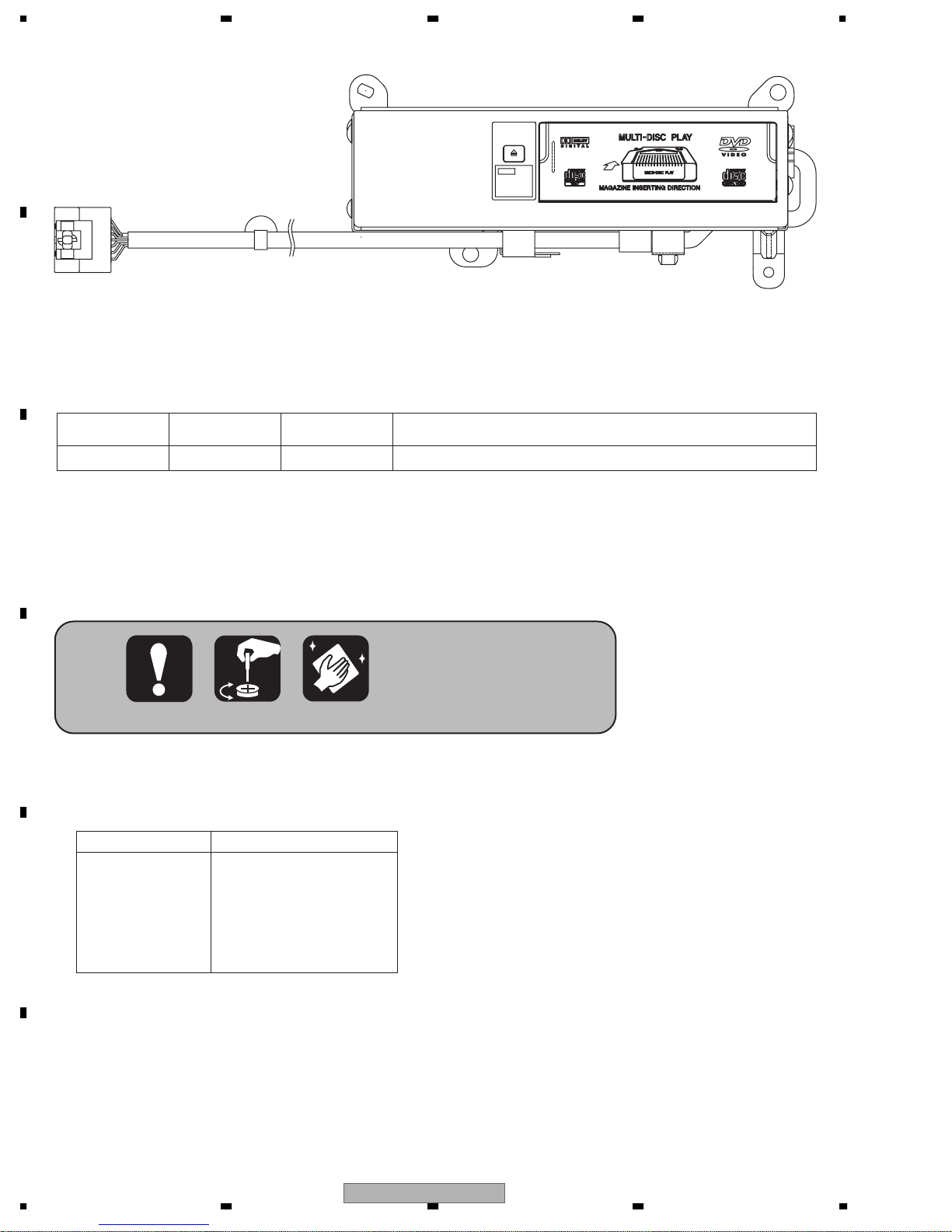
CD-Rs may not
be playable in
this compact
disc player.
B
This service manual should be used together with the following manual(s):
Model No. Order No. Mech. Module Remarks
CX-692 CRT2533 MM-1 DVD/CD Mech. Unit : Circuit Description, Mech. Description, Disassembly
C
XDV-M8357ZT/UC and XDV-M8357ZT-91/UC have adopted AVC-LAN.
Manufactured under license from Dolby Laboratories. "Dolby" and the double-D symbol are trademarks
of Dolby Laboratories.
D
For details, refer to "Important Check Points for Good Servicing".
The supplementary models are identical with the original ones except for the following items.
* : Non spare part
Description
Polyethylene Bag
* Air Cap
Carton
E
Contain Box(x1/2)
Protector
XDV-M8357ZT-91/UC
CEG1181(Unit)
CEG1288(Connector)
CHG4170
CHL5166
CHP2341(TOP)
Protector
F
2
1234
CHP2342(BOTTOM)
XDV-M8357ZT/UC

5678
SAFETY INFORMATION
CAUTION
This service manual is intended for qualified service technicians; it is not meant for the casual do-it-yourselfer.
Qualified technicians have the necessary test equipment and tools, and have been trained to properly and safely repair
complex products such as those covered by this manual.
Improperly performed repairs can adversely affect the safety and reliability of the product and may void the warranty.
If you are not qualified to perform the repair of this product properly and safely, you should not risk trying to do so
and refer the repair to a qualified service technician.
W
ARNING
This product contains lead in solder and certain electrical parts contain chemicals which are known to the state of
California to cause cancer, birth defects or other reproductive harm.
Health & Safety Code Section 25249.6 - Proposition 65
- DVD Player Service Precautions
1. You should conform to the regulations governing the
product (safety, radio and noise, and other regulations),
and should keep the safety during servicing by following
the safety instructions described in this manual.
2. Never adjust the LD VR in the pickup unit to protect
the pickup from electrical damages.
3. For pickup unit(CGY2020) handling, please refer to
"Disassembly".
During replacement, handling precautions shall be
taken to prevent an electrostatic discharge(set the short
switch of the pickup unit to the SHORT side).
4. During disassembly, be sure to turn the power off since
an internal IC might be destroyed when a connector
is plugged or unplugged.
5. Please adjusting the skew after changing the pickup
unit.
A
B
C
is a trademark of DVD Format/Logo Licensing Corporation.
D
E
F
56
XDV-M8357ZT/UC
7
8
3

1234
[Important Check Points for Good Servicing]
In this manual, procedures that must be performed during repairs are marked with the below symbol.
Please be sure to confirm and follow these procedures.
A
B
C
D
1. Product safety
Please conform to product regulations (such as safety and radiation regulations), and maintain a safe servicing environment by
following the safety instructions described in this manual.
1 Use specified parts for repair.
Use genuine parts. Be sure to use important parts for safety.
2 Do not perform modifications without proper instructions.
Please follow the specified safety methods when modification(addition/change of parts) is required due to interferences such as
radio/TV interference and foreign noise.
3 Make sure the soldering of repaired locations is properly performed.
When you solder while repairing, please be sure that there are no cold solder and other debris.
Soldering should be finished with the proper quantity. (Refer to the example)
4 Make sure the screws are tightly fastened.
Please be sure that all screws are fastened, and that there are no loose screws.
5 Make sure each connectors are correctly inserted.
Please be sure that all connectors are inserted, and that there are no imperfect insertion.
6 Make sure the wiring cables are set to their original state.
Please replace the wiring and cables to the original state after repairs.
In addition, be sure that there are no pinched wires, etc.
7 Make sure screws and soldering scraps do not remain inside the product.
Please check that neither solder debris nor screws remain inside the product.
8 There should be no semi-broken wires, scratches, melting, etc. on the coating of the power cord.
Damaged power cords may lead to fire accidents, so please be sure that there are no damages.
If you find a damaged power cord, please exchange it with a suitable one.
9 There should be no spark traces or similar marks on the power plug.
When spark traces or similar marks are found on the power supply plug, please check the connection and advise on secure
connections and suitable usage. Please exchange the power cord if necessary.
0 Safe environment should be secured during servicing.
When you perform repairs, please pay attention to static electricity, furniture, household articles, etc. in order to prevent injuries.
Please pay attention to your surroundings and repair safely.
2. Adjustments
To keep the original performance of the products, optimum adjustments and confirmation of characteristics within specification.
Adjustments should be performed in accordance with the procedures/instructions described in this manual.
3. Lubricants, Glues, and Replacement parts
Use grease and adhesives that are equal to the specified substance.
E
Make sure the proper amount is applied.
4. Cleaning
For parts that require cleaning, such as optical pickups, tape deck heads, lenses and mirrors used in projection monitors, proper
cleaning should be performed to restore their performances.
5. Shipping mode and Shipping screws
To protect products from damages or failures during transit, the shipping mode should be set or the shipping screws should be
installed before shipment. Please be sure to follow this method especially if it is specified in this manual.
F
4
1234
XDV-M8357ZT/UC

5678
CONTENTS
SAFETY INFORMATION......................................................................................................................................3
1. SPECIFICATIONS.............................................................................................................................................6
2. EXPLODED VIEWS AND PARTS LIST.............................................................................................................8
2.1 EXTERIOR .................................................................................................................................................8
2.2 DVD/CD MECHANISM UNIT....................................................................................................................10
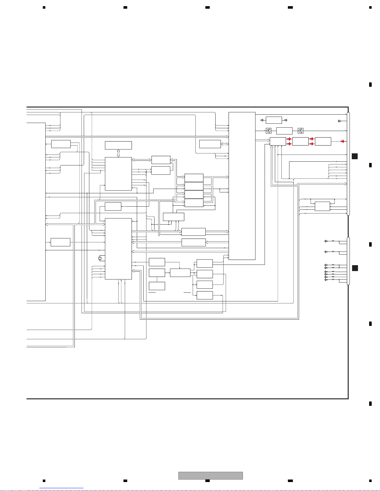
3. BLOCK DIAGRAM AND SCHEMATIC DIAGRAM ..........................................................................................12
3.1 BLOCK DIAGRAM....................................................................................................................................12
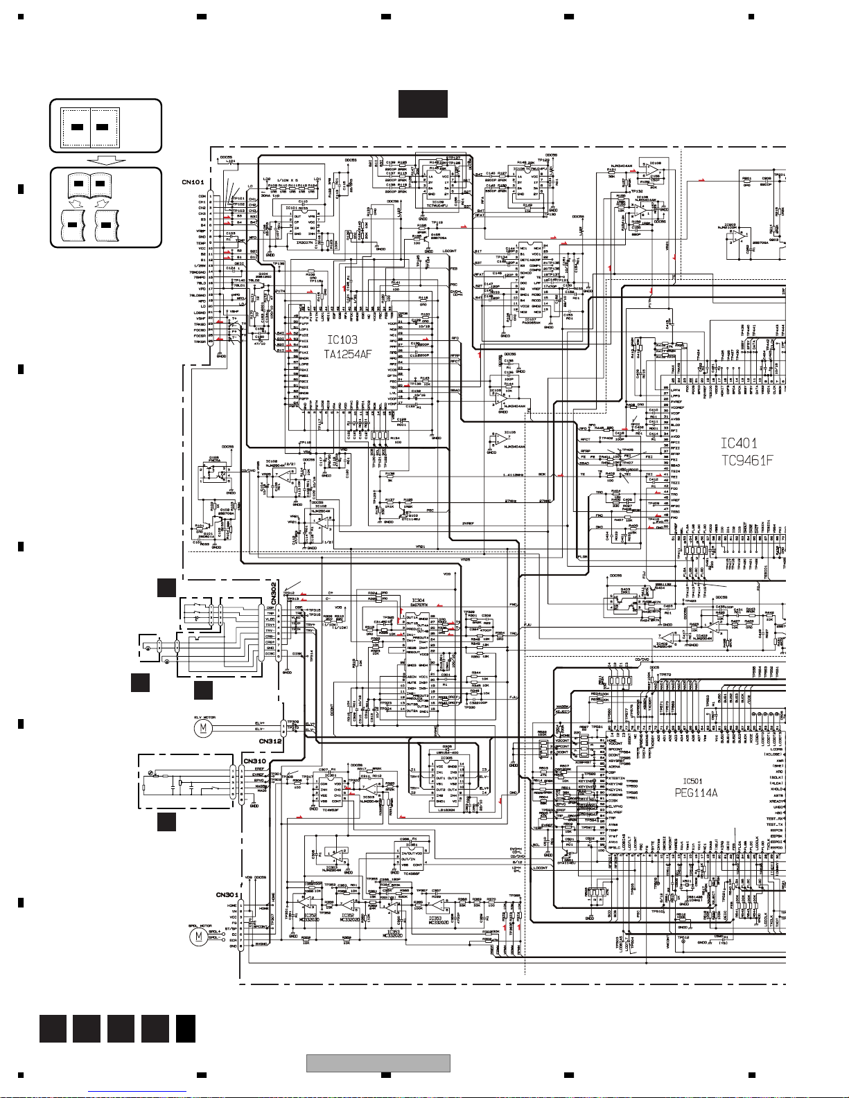
3.2 DVD/CD MECHANISM UNIT, MAIN PCB(SERVO SECTION)(GUIDE PAGE).........................................16
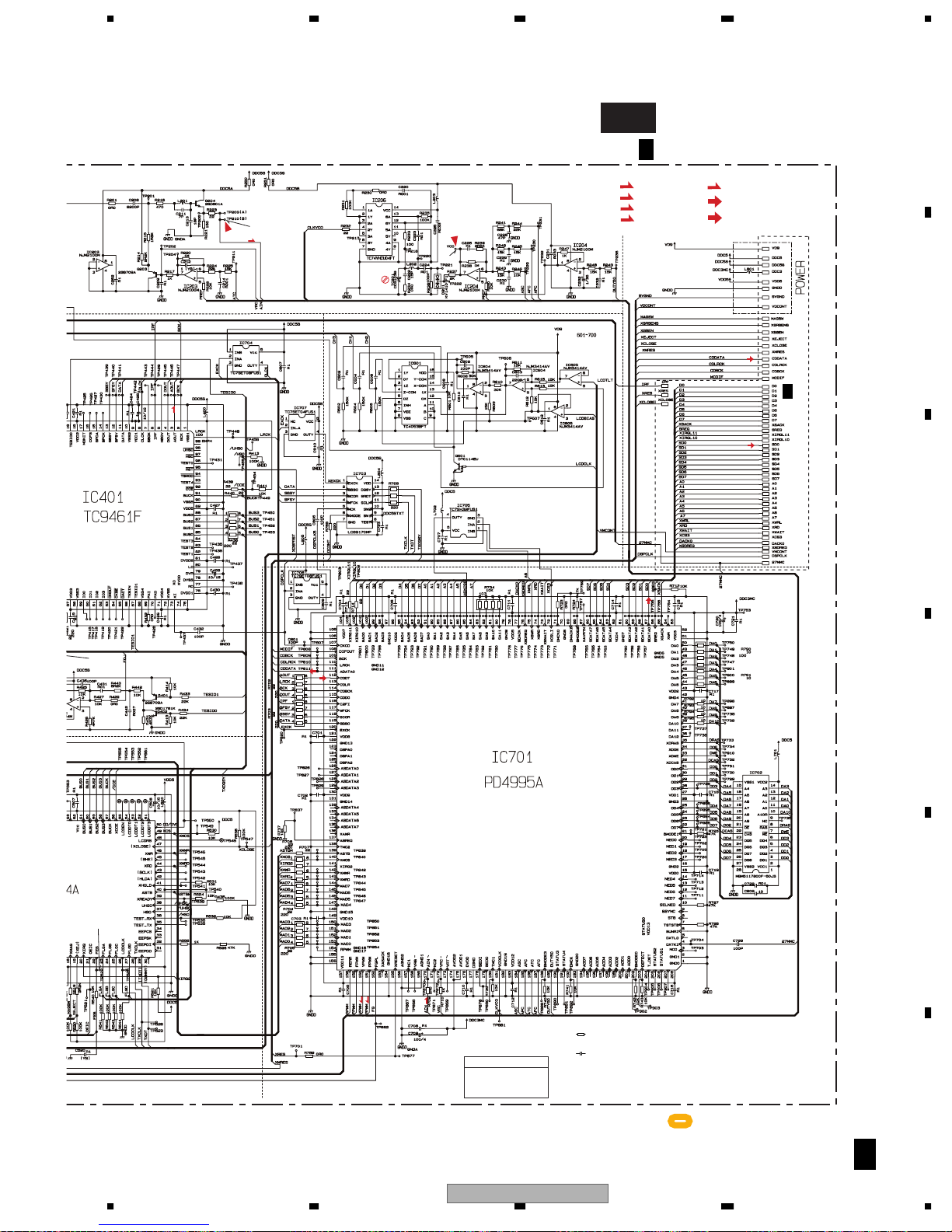
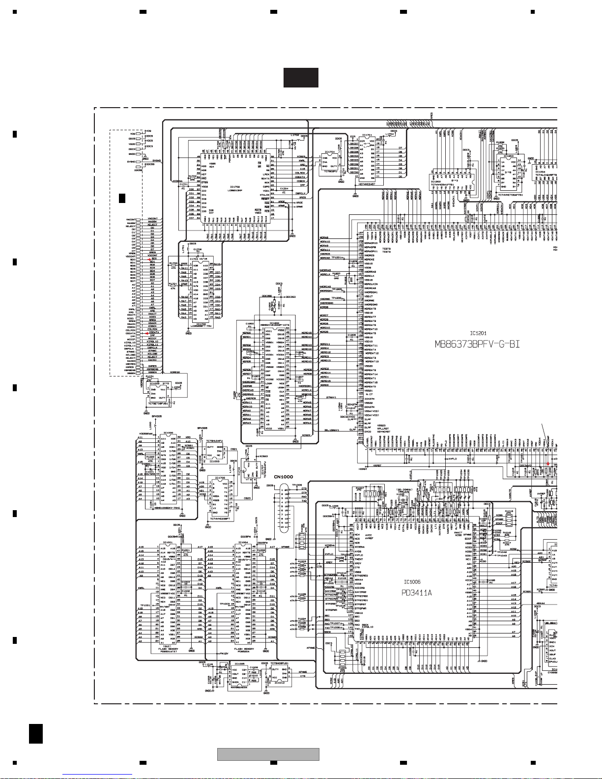
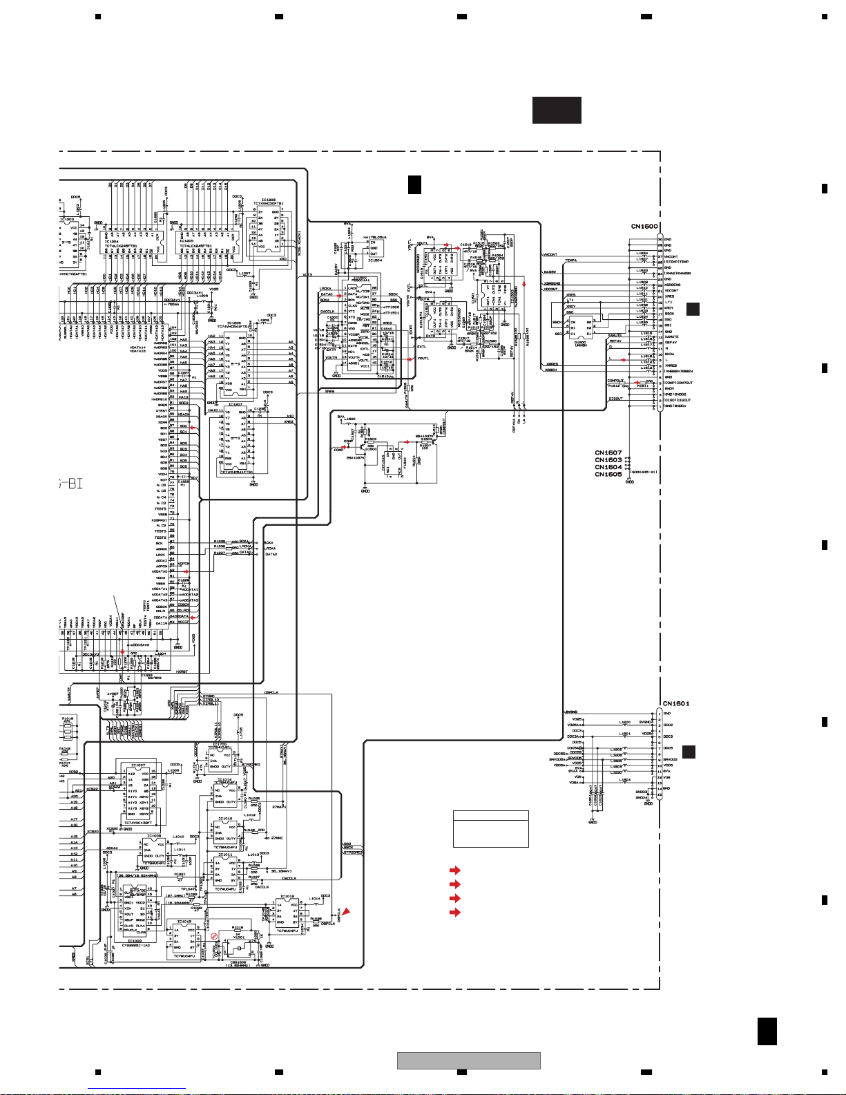
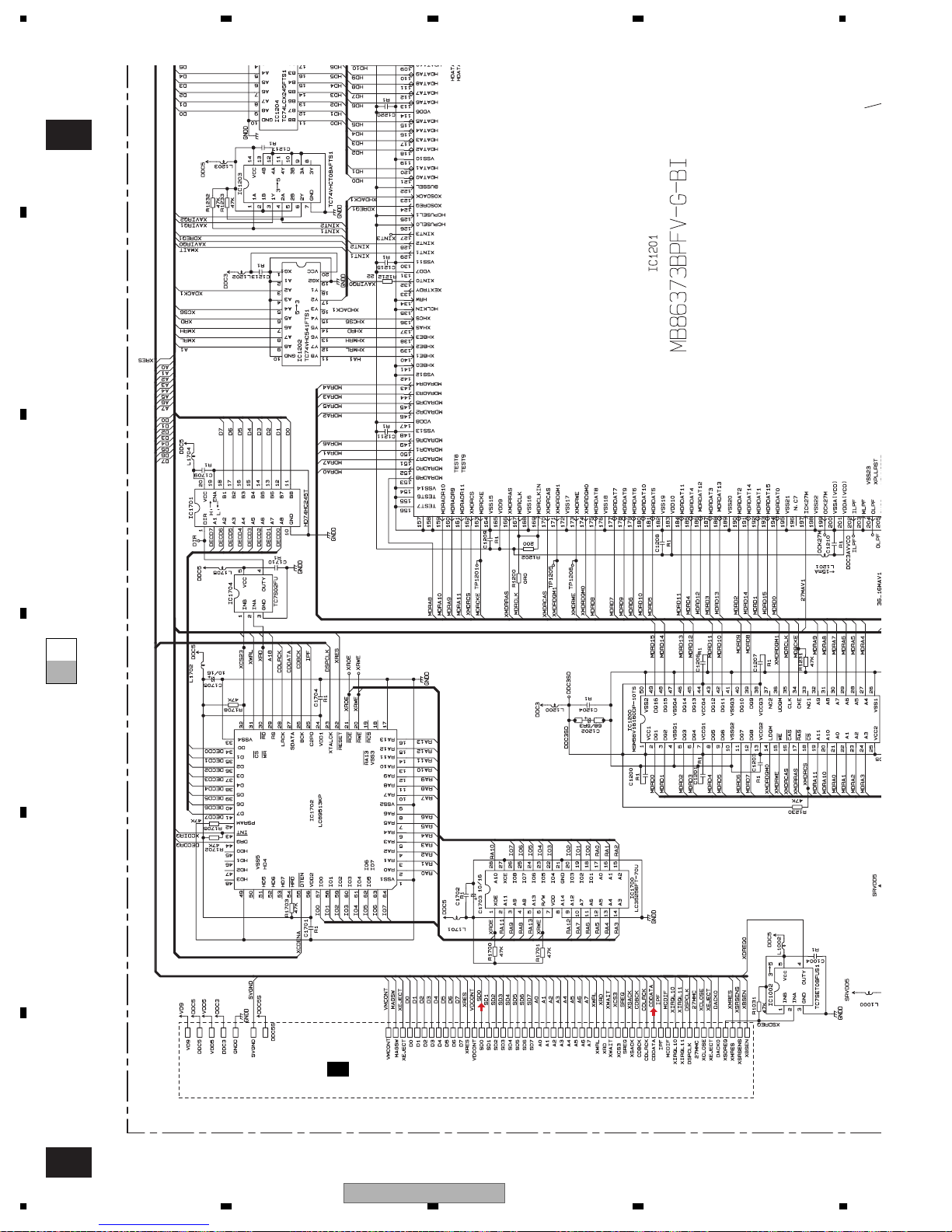
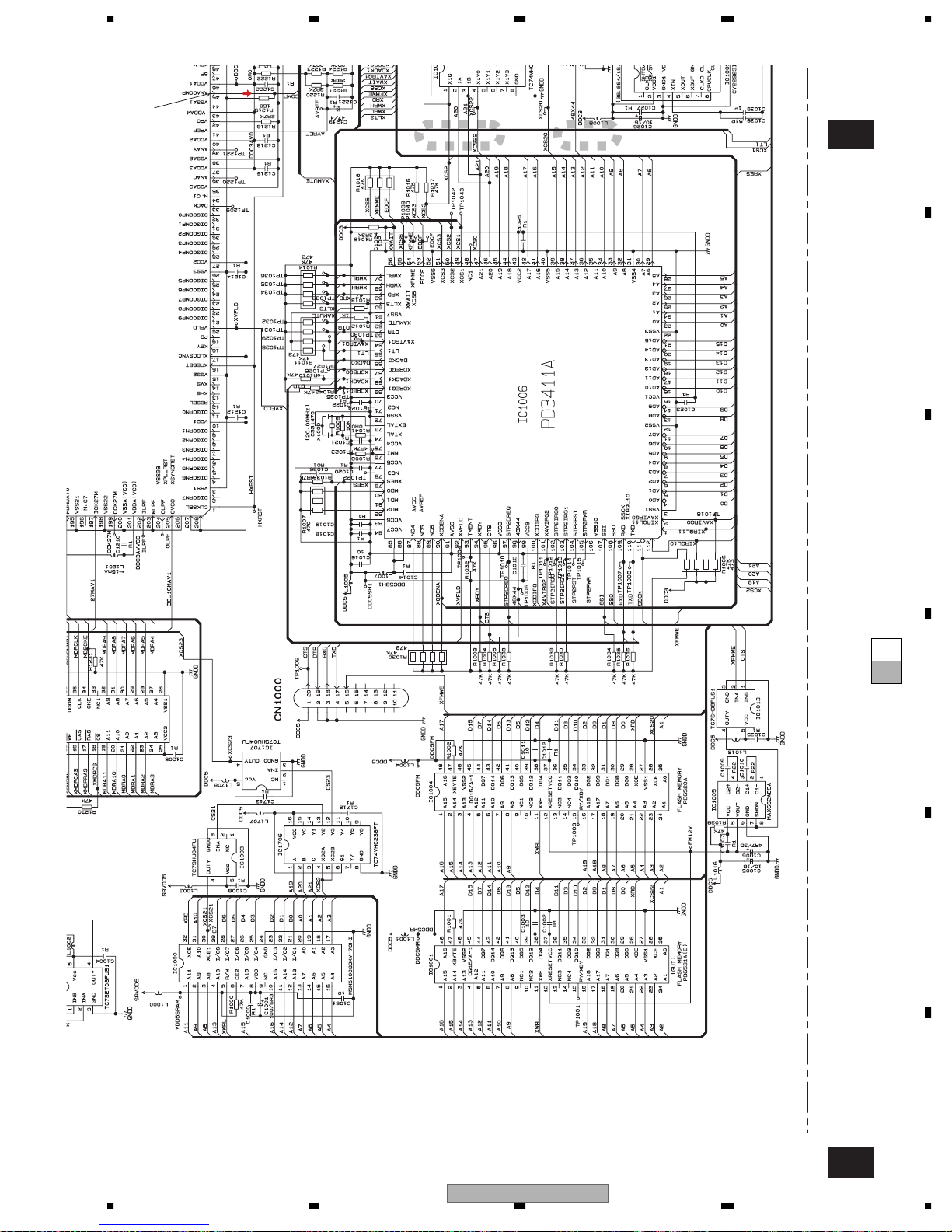
3.3 MAIN PCB(DECODER SECTION)(GUIDE PAGE)...................................................................................26
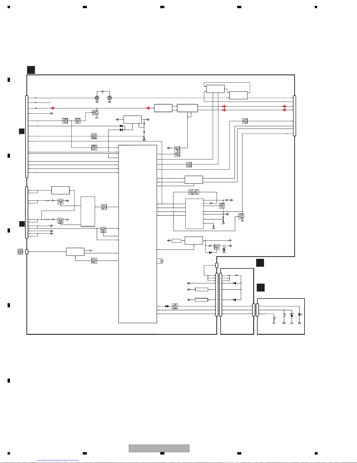
3.4 EXTENSION UNIT....................................................................................................................................32
3.5 KEYBOARD PCB .....................................................................................................................................38
3.6 MF UNIT...................................................................................................................................................39
4. PCB CONNECTION DIAGRAM......................................................................................................................40
4.1 MAIN PCB ................................................................................................................................................40
4.2 EXTENSION UNIT....................................................................................................................................44
4.3 KEYBOARD PCB .....................................................................................................................................48
4.4 MF UNIT...................................................................................................................................................49
4.5 DVD/CD MECHANISM UNIT....................................................................................................................50
5. ELECTRICAL PARTS LIST.............................................................................................................................54
6. ADJUSTMENT................................................................................................................................................65
6.1 JIG CONNECTION DIAGRAM.................................................................................................................65
6.2 MAIN UNIT ADJUSTMENT......................................................................................................................67
6.3 SKEW ADJUSTMENT..............................................................................................................................68
6.4 ELEVATION ADJUSTMENT .....................................................................................................................70
6.5 TEST MODE.............................................................................................................................................74
7. GENERAL INFORMATION .............................................................................................................................92
7.1 DIAGNOSIS..............................................................................................................................................92
7.1.1 DISASSEMBLY......................................................................................................................................92
7.1.2 CONNECTOR FUNCTION DESCRIPTION ..........................................................................................95
7.2 IC..............................................................................................................................................................96
7.3 EXPLANATION.......................................................................................................................................115
7.3.1 OPERATIONAL FLOW CHART...........................................................................................................115
7.3.2 SYSTEM BLOCK DIAGRAM...............................................................................................................116
8. OPERATIONS ...............................................................................................................................................117
A
B
C
D
E
F
56
XDV-M8357ZT/UC
7
8
5

1234
1. SPECIFICATIONS
A
General
System .................................... DVD-Video, Video CD,
Usable discs .... DVD-Video, Video CD, Compact disc
Signal format
1.Linear PCM
.................... Sampling frequency: 44.1/48/96 kHz
Number of quantization bits: 16/20/24; linear
2.Dolby digital
3.MPEG
Power source ...... 13.2 V DC (10.5 – 16.1 V allowable)
Grounding system .................................. Negative type
Rated current ................ 1.0 A or less(DVD regenerate)
Region Number
B
.............................................................................. 1
Backup current ...........................................5mA or less
Audio
Frequency response .................... ±1.5dB(20Hz,20kHz)
Signal-to-noise ratio
.......................................................... 80dB or more
Residual distortion .................................... 0.1% or less
Output Level ............................ 1000 mV (1 kHz, 0 dB)
Number of channels ...................................... 2 (stereo)
Max. output power supply ..........................2Vrms±2dB
Separation..................................................65dB or more
The difference between right output and left output
C
............................................................1.5dB or less
Compact disc audio system
Player
Weight ................................................................ 2660 g
Video
Output level .......................... 1000 mVp-p±0.2 V/75 Ω
D
E
F
6
1234
XDV-M8357ZT/UC

5678
A
B
C
D
E
56
XDV-M8357ZT/UC
F
7
8
7

N
1234
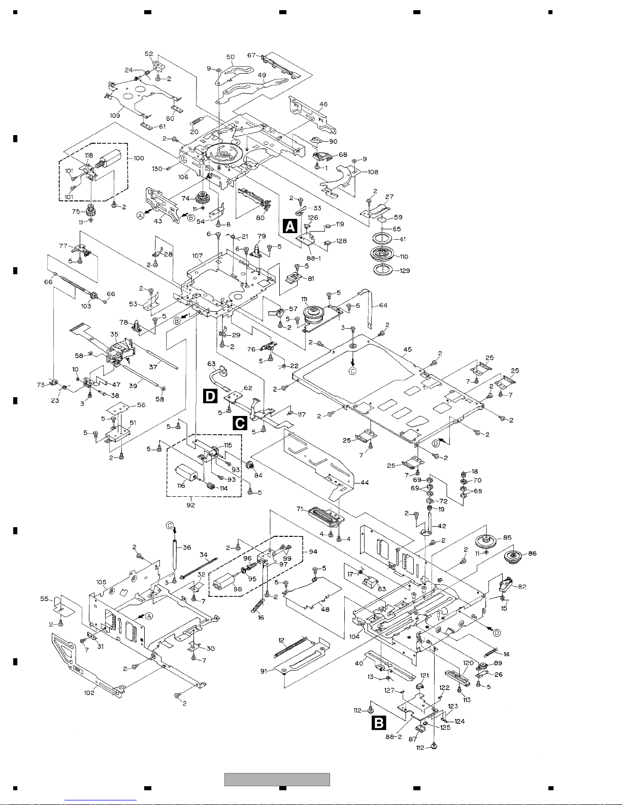
2. EXPLODED VIEWS AND PARTS LIST
OTES : • Parts marked by " * " are generally unavailable because they are not in our Master Spare Parts List.
• The > mark found on some component parts indicates the importance of the safety factor of the part.
A
Therefore, when replacing, be sure to use parts of identical designation.
• Screw adjacent to mark on the product are used for disassembly.
• For the applying amount of lobricants or glue, follow the instructions in this manual.
(In the case of no amount instructions,apply as you think it appropriate.)
2.1 EXTERIOR
B
"
C
D
E
F
8
1234
XDV-M8357ZT/UC

5678
EXTERIOR SECTION PARTS LIST
Mark No. Description Part No.
1 Screw BSZ30P055FTC
2 Screw(M2x4) CBA1676
3 Screw(M3x12) CBA1819
4 Screw(M2x3.5) CBA1966
5 Spring CBH2335
6 Connector CDE6302
7 Cord Assy CDE6983
8 Clamper CNV7278
9 Clamper CNV7279
10 Upper Case CNB2496
11 Holder CNC8612
12 Bracket CNC8831
13 Bracket CNC8832
14 Shield CNC9089
15 Insulator CNM6337
16 Insulator CNM6405
17 Filter CNM6600
18 Insulator CNM6735
19 Cushion CNM6743
* 20 Insulator CNM6906
21 Insulator CNM6985
22 Cushion CNM7037
* 23 Insulator CNM7090
24 Cushion CNM7347
25 Cushion CNM7872
26 PCB CNP5534
27 PCB CNP5535
28 PCB CNP5604
29 Panel CNS8228
30 Damper CNV5833
31 Holder CNV6181
32 Holder CNV8121
33 MF Unit CWM6518
34 Plug(CN2903) CKS1051
35 Connector(CN2901) CKS3563
36 Holder CNC2218
37 Shield CNC8898
38 Insulator CNM6836
39 Main Unit CWX3187
40 Terminal(CN1603) CKF1064
41 Terminal(CN1604) CKF1064
42 Terminal(CN1605) CKF1064
43 Terminal(CN1607) CKF1064
44 Connector(CN1601) CKS1953
45 Connector(CN101) CKS1964
46 Connector(CN312) CKS2191
47 Connector(CN2000) CKS2193
48 Connector(CN302) CKS3480
49 Connector(CN1600) CKS3749
50 Connector(CN310) CKS3767
Mark No. Description Part No.
55 Cord CDE6446
56 Terminal(CN3810) CKF1064
57 Terminal(CN3811) CKF1064
58 Terminal(CN3812) CKF1064
59 Terminal(CN3813) CKF1064
60 Connector(CN3951) CKS1953
61 Connector(CN3891) CKS2191
62 Connector(CN3301) CKS2619
63 Connector(CN3302) CKS2619
64 Plug(CN3802) CKS3535
65 Connector(CN3961) CKS3749
66 Connector(CN3801) CKS4320
67 Connector(CN3803) CKS4356
68 Holder CNC8400
69 Shield CNC8899
70 Shield CNC8900
71 Insulator CNM6834
72 Insulator CNM6835
73 Arm Unit CXA8606
74 Rear Frame Unit CXB6364
75 Lower Case Unit CXB6365
76 Button(EJECT) CAC6152
77 Door CAT2385
78 Spring CBH2336
79 Spring CBH2337
80 Spring CBH2363
81 Connector CDE6022
82 Holder CNC8402
83 Holder CNC8409
84 Cushion CNM6407
85 Cushion CNM6842
86 Cushion CNM6843
* 87 Insulator CNM6907
88 Lever CNV5831
89 Lever CNV6104
90 Damper Unit CXB4206
91 Screw IMS20P035FTB
92 Screw IMS26P040FTC
93 DVD/CD Mechanism Unit(MM-1)CXK7020
94 Fan Motor CXM1195
95 Grille CNS6472
96 Screw IMS30P060FTB
97 Screw ISS30P060FTC
98 Screw PMB26P050FTC
99 Screw TMZ50P060FTC
* 100 Tape CNM7273
101 IC(IC3821) BA00AST
102 Transistor(Q3811) 2SB942A
A
B
C
D
E
51 Connector(CN301) CKS4358
52 Connector(CN1000) CKS4374
53 Extension Unit CWX3198
54 Screw BMZ26P050FTC
56
XDV-M8357ZT/UC
F
7
8
9
1234
2.2 DVD/CD MECHANISM UNIT
A
B
C
D
E
F
10
1234
XDV-M8357ZT/UC

5678
DVD/CD MECHANISM UNIT SECTION PARTS LIST
Mark No. Description Part No.
1 Screw(M2x4) CBA1026
2 Screw(M2x2.5) CBA1651
3 Screw(M2x2.5) CBA1041
4 Screw(M2x3.5) CBA1674
5 Screw(M2x3) CBA1154
6 Screw(M2x2) CBA1243
7 Screw(M2x1.4) CBA1687
8 Screw(M2x2.2) CBA1965
9 Washer CBF1002
10 Washer CBF1037
11 Washer CBF1038
12 Spring CBH2368
13 Spring CBH1827
14 Spring CBH1828
15 Spring CBH1829
16 Spring CBH1830
17 Spring CBH1919
18 Spring CBH1930
19 Spring CBH2070
20 Spring CBH2091
21 Spring CBH2159
22 Spring CBH2227
23 Spring CBH2238
24 Spring CBH2279
25 Spring CBL1307
26 Spring CBL1362
27 Spring CBL1388
28 Spring CBL1416
29 Spring CBL1417
30 Spring CBL1418
31 Spring CBL1419
32 Spring CBL1420
33 Spring CBL1422
34 Connector CDE6156
35 PU Unit CGY2020
36 Shaft CLA2803
37 Shaft CLA3428
* 38 Shaft CLA3431
39 Shaft CLA3562
40 Lever CNC6194
41 Plate CNC6847
42 Holder CNC7448
43 Lever CNC7975
44 Lever CNC8065
45 Frame CNC8068
46 Lever CNC8097
47 Bracket CNC8106
48 Cover CNC8129
49 Arm CNC8335
50 Arm CNC8336
* 51 Cover CNC8347
52 Holder CNC8476
53 Cover CNC8921
54 Cover CNC8922
55 Cover CNC8923
56 Plate CNC9010
57 Cover CNC9083
58 Cushion CNM6301
59 Spacer CNM6334
60 Sheet CNM6385
61 Sheet CNM6581
62 PCB CNP5371
63 PCB CNP5380
64 PCB CNP5381
65 Ball CNR1189
No. Description Part No.
Mark
66 Bearing CNR1415
67 Rail CNV4420
68 Lever CNV4422
69 Guide CNV4597
70 Guide CNV4722
71 Rack CNV4828
72 Guide CNV5193
* 73 Rack CNV5451
74 Gear CNV5658
75 Gear CNV5659
76 Holder CNV5661
77 Holder CNV5662
78 Guide CNV5663
79 Guide CNV5664
80 Rail CNV5668
81 Guide CNV5671
82 Arm CNV5868
83 Arm CNV6158
84 Gear CNV6226
85 Gear CNV6242
86 Gear CNV6285
87 Connector(CN301) CKS3476
88 PCB CNX3040
89 Damper Unit CXA7159
90 Plate Unit CXB2262
91 Lever Unit CXB2266
92 Motor Unit(Carriage)(M1) CXC1552
93 Screw JFZ20P025FNI
94 Motor Unit(ELV)(M4) CXC1540
* 95 Gear CNV6239
96 Gear CNV6240
* 97 Bracket Unit CXB5838
* 98 Motor CXM1220
99 Screw JFZ20P025FNI
100 Motor Unit(Tray)(M2) CXC1541
101 Screw JFZ20P025FNI
102 Lever Unit CXB3933
103 Screw Unit(-D) CXB3934
104 Magazine Holder Unit CXC5000
105 Frame Unit CXB3970
106 Chassis Unit CXB3972
107 Chassis Unit CXB3975
108 Lever Unit CXB3976
109 Arm Unit CXB4318
110 Clamper CNV5667
111 Motor(Spindle)(M3) CXM1282
112 Screw IMS26P040FMC
113 Screw JFZ17P020FNI
* 114 Gear CNV6225
* 115 Bracket Unit CXB4003
* 116 Motor CXM1221
117 Photo T ransistor(Q851) PT4800
* 118 Bracket Unit CXB3971
119 LED(D851) CN504-2
120 Resistor(VR301) CCW1021
121 Switch(S301) CSN1044
122 Capacitor(C301) CKSRYB104K16
123 Resistor(R301) RS1/16S562J
124 Resistor(R302) RS1/16S622J
125 Semi-fixed(VR302) CCP1338
126 Switch(S852) CSN1052
127 Capacitor(C302) CKSRYB103K50
128 Switch(S851) CSN1051
129 Sheet CNM9776
130 Screw ZMK30H025FZB
A
B
C
D
E
F
56
XDV-M8357ZT/UC
7
8
11
F
K
K
K
A
3
0
K
Q
F
C
H
C
E
7
1234
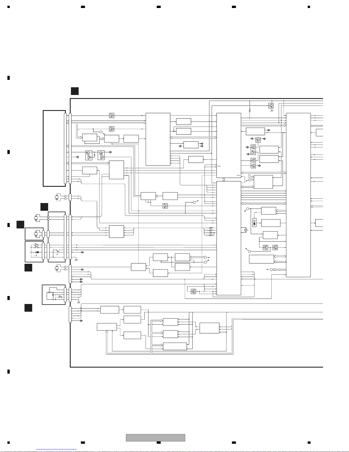
3. BLOCK DIAGRAM AND SCHEMATIC DIAGRAM
3.1 BLOCK DIAGRAM
A
MAIN PCB
E
CN101
B
PU UNIT
C
M3
ELV
MOTOR
PCB(A)
C
M1
CRG
M
MOTOR
PCB(B)
D
M2
TRAY
MOTOR
S852
DSP
S851
TRP
D
A
11
M
22
11
22
33
44
M4
SPDL
MOTOR
PCB UNIT(A)
VR302
VR301
PCB UNIT(B)
B
78LD
16
78MPD
15
B1I-B4I
12
.
11
.
5
RFA
.
6
IC109
TC7WU04FU
B1I-B4I
F+,F-,T+,T-
ELV+
ELV-
CRG+
CRG-
TRY+
TRY-
DSP
TRP
DISC
VLED
GND
EC
ECR
FG
HOME
ST/SP
VM
VCC
EREF
EVREF
EPVO
MAGSW
GND
XFMWE
CTS
DTR
RXD
TXD
VCC
VREF
1
IR3C07N
VD9
VR25
VD9
DDC5S
DDC5
IC106
Q102
IC101
3
CH1,CH2,CH3
2
-
4
VSHF
22
VREF
7
23
-
26
LD
20
MPD
19
TEMP
9
1/2SW
13
CN312
1
M
2
CN302
7
7
6
6
4
4
5
5
1
1
2
2
Q851
9
9
3
3
8
8
CN301
6
M
7
4
1
5
2
3
CN310
1
1
2
2
MAG
3
3
4
4
S301
5
5
CN1000
16
20
19
18
17
1
E
Q104
Q165
RFA
A
IC107
PA0065AM
5
Q168Q101
DDC5S
MOTOR DRIVER
IC304
5
BA6797FM
1
CRG+
2
CRG-
MOTOR DRIVER
ELV+
10
ELV-
12
IC305
3
LB1836M
5
2
IC1013
1
TC7SH08FUS1
ADDRESS DECODER
IC1706
TC74VHC238FT
4,5
A19-A21
19
2461
IC108(1/2)
NJM3404AM
19
24
4
9
9
13
2
6
48
MAX662AESA
CS23
2
TC7SHU04FU
12
2
CS21
TC7SHU04FU
I4
I3
I1
I2
1
TC4W53F
SELECTOR
IC1005
IC1707
IC1003
IC301
SPDL
45
44
41
IC601
TC4053BFT
5
6
4
4
XCS21
LDO1
MDI1
RFA
P1TN
6
7
10911
1
7
IC103
TA1254AF
RF AMP
IC352
MC33202D
3,5
CD SPDL
IC303
NJM2904M
D0-15
A1-19
D0-15
A1-19
D0-7
A0-16
28
RFO
21
21
FEO
6
20
TEO
7
VRD
DDC5S
16
VRCK
35
PSC
13
SCB
14
SCL
15
SCD
34
FEB
IC604, 605
NJM3414AV
Q601
DVD SPDL
6
1
2
6
FLASH RAM
IC1001
12
PD6531A
FLASH RAM
IC1004
12
PD6520A
SDRAM
IC1000
30
M5M51008DKV-70HI
IC105
NJM3404AM
7
IC108(2/2)
NJM3404AM
SBAD,FLGB,RFCT,RFPR
3
IC102
57
NJM2904M
SCB
F JUMP
SCL
12
IC353
MC33202D
IC351
TC4S66F
XCS23
11
26
XCS22
28
11
26
XCS20
28
DCONT
FG
XWRL
5
32
IC402
NJM2904M
FPWM,VPWM
PPWM,RPWM
3
4
Q501
XRD
D
EVREF
ADDRESS DECODER
10
SCD
FEB
1
VR21
VR25
BUCK
/CCE
SCB
SCL
SCD
FEB
BUCK
/CCE
I4
I2
I3
I1
B
C
ST/SP
EREF
EPVO
MAGSW
4
IC1007
TC74VHC139FT
33
38
47
41
43
91
92
44
48
50
BUS0-3
6
2
100
1
22
3
4
57
56
26
50
84
97
21
5
80
79
78
87
95
92
10
7
81
83
94
86
93
18
98
RFI
FEI
TEBC
TEI
IC401
TC9461F
DSP
FOO
BUCK
CCE
TRO
FMO
DMO
FLGA,FLGB,FLGC,FLGD
PSC
RFSCB
RFSLC
RFSCD
FEB
LCDBIAS
LCDTLT
BUCK
XCCE
LCDCLK
CD/DVD
DCONT
TEMP
OEIC
LDCONT
I4
I2
IC501
I3
PEG114A
MECHANISM
CONTROLLER
DSP
TRP
DISK
DSCSIZ
FG
HOME
SPCONT
ELVREF
ADENA
ELVPVO
XMAG
Vref
XCS2
2
3,13
1,15
XCS2
A20
A21
CLCK
TESIO1
TESIO0
XSYSRST
ASTB
XIRQ
VMCONT
VDCONT
BSENS
SRSENS
XMRES
BCK
XI
IPF
RST
XCS
XWR
XRD
Xout
Xin
2
73
6
8
4
TC7SET08FUS1
DDC5S
VRA
DDC5S
67
19
95
D
85
TXDQSY
TXDT,TXCLK
40
49
20
46
44
C
13
15
X501
10MHz
A
VMCONT
11
82
VDCONT
74
XBSEN
75
XSRSENS
XMRES
12
MAGSW
BCK
DOUT,LRCK,AOUT
1
IC704
2
Q404
2VREF
Q403
IC706
TC7SET08FUS1
Q401
IC707
TC7SET04FUS1
VR21
Q402
DATA,SFSY,SBSY
IC703
6
LC89170MP
ASTBM
XMCS
XIRQ2
XMWR
XMRD
MAD0-MAD7
1,5
IC204
7
NJM2100M
12,13
IC206
TC74VHCU04FT
5
IC203
7
NJM2100M
Q203 Q204
RFA
DRAM
IC702
MSM5117800F-60JS
DDC5S
B
Q103
2
4
2
4
5
1
ASC,AFC
3
6
DD0-7
DCAS,DWE
DOE,DRAS
DA0-10
FPWM,VPWM
PPWM,RPWM
27MMC
4
DXTKI
114
CDBCK
107
116
120
CKCD
C2F1
EXCK
IC701
PD4995A
ADATAO
ASIC
XRESET
139
ASTB
140
XMCS
141
XIRQ2
142
XMWR
143
XMRD
APC
189
DUTY50
181
4
186
172
170
162
VCOCLK
ATC
VRC
AIN
FGPL
XSDREQ
LRCK
XCSLI
XIRQ11
XIRQ10
XSACK
SREQ
DIFOUT
XSWAIT
XSWR
XSRD
SDACK
IP
DSPCL
CDBC
109
BCK
110
CDLRC
111
CDDAT
I
85
4
SA6
TC7S
72
XCS
103
XIRQL11
102
XIRQL1
XSAC
55
56
SRE
108
MCDI
165
73
75
XWRL
74
XRD
D0-D7,A0-A
I
76
2
TC7S
77
F
12
1234
XDV-M8357ZT/UC
5678
A
IC701
PD4995A
ASIC
ADATA O
XCSLI
XIRQ11
XIRQ10
XSACK
SREQ
DIFOUT
XRESET
XSWAIT
XSWR
XSRD
XSDREQ
SDACK
LRCK
BCK
SA6
DSPCLK
CDBCK
109
110
CDLRCK
111
CDDATA
85
4
TC7SH32FUS1
72
103
XIRQL11
102
XIRQL10
XSACK
55
56
108
MCDIF
165
73
75
XWRL
74
D0-D7,A0-A7
76
2
TC7SET08FUS1
77
XCS3
SREQ
XRD
IPF
IC705
IC1002
A6
1
2
XCS3
XRES
4
D0-D15,A0-A21
D0-D15,A0-A21
20.000MHz
XRES
X1000
CDBCK
CDLRCK
CDDATA
IPF
DSPCLK
XCS3
XIRQL11
XIRQL10
CTS
DTR
RXD
TXD
XFMWE
26
28
27
25
23
29
A18
4
97
51
1
112
67
66
74
73
95
63
109
110
54
IC1700
LC35256FT-70U
BCK
LRCK
SDATA
C2PO
XTALCK
IC1702
LC89513KP
RS
IC1705
TC7SHU04FU
STP2DREQ
XCS3
XIRQL11
XIRQL10
XDREQ0
IC1006
PD3411A
DACK0
XTAL
EXTAL
CTS
DTR
RXD
TXD
XFMWE
60 79 50
XLT3
IO0-7,RA0-13,
XROE,XRWE
2
XWAIT
XCDENA
XCDIRQ
48X44
XAMUTE
XLT3
XRES
XCS2
XRES
reset
dten
DRQ
cs
rd
wr
int
SD0-SD7
DECD0-DECD7
32
30
31
XCDENA
55
44
DECDRQ
XCDIRQ
43
22
XRES
56
90
XCDENA
100
XCDIRQ
98
62
XCS23
XRD
XWRL
SSI,SSO,SSCK,XRDY,LT1
BUS BUFFER
HD74HC245T
1
2
TC7S02FU
XWRL
XRD
IC1008
2
TC7SHU04FU
IC1015
TC7WU04FU
X1001
13.824MHz
D0-7
IC1701
1
IC1704
4
86
IC1208
TC74VHC00FTS1
1
13
12
XRD
XRD,XWRL,
XWRH,XCS6,
XCS6
XDACK1
A1 HA1
XVFLD,XAVIRQ0,XDREQ1
4
7
4
CY2292SI-1A0
CLOCK GENERATOR
5V-3V LEVEL SHIFT
A2-9
IC1206
TC74VHC541FTS1
A10
IC1207
8
TC74VHC541FTS1
D0-7
IC1204
1
TC74LCX245FTS1
D8-15
IC1205
TC74LCX245FTS1
1
2,9
5V-3V LEVEL SHIFT
XDACK1
IC1202
TC74VHC541FTS1
3V-5V LEVEL SHIFT
IC1203
TC74VHCT08AFTS1
15
IC1009
1
3
8
1
10
9
3
2
2
TC7WU04FU
TC7WU04FU
TC7SHU04FU
TC7SHU04FU
IC1200
MSM56V16160DP-10TS
SDRAM
HA2-9
HA2-10,HD0-15
HA10
12
HD0-7
19
HD8-15
19
XHRD,XHWRL,XHWRH
XHCS6,XHDACK1
11
XINT1,XINT2XAVIRQ1,XAVIRQ2
6,7
IC1011
5
IC1012
5
IC1014
4
IC1010
4
CDBCK
CDLRCK
CDDATA
XSACK
SREQ
MCDIF
OVCO
DACCLK
DSPCLK
ICK27M
27MMC
56
CDBCK
55
CDLR
54
CDDATA
89
XSACK
91
SREQ
53
DAIIN
IC1201
MB86373BPFV-G-BI
MPEG DECODER
16
XRESET
1
CLKSEL
XHBE1
140
133
XEXTRDY
205
OVCO
197
ICK27M
64
AODAI
31
8VA DAC5V
Q1500
45
ANACOMP
BCKA
LRCKA
DATA0
IC1504
HA178L05UA
3
DAC
IC1500
PE8001A1
5
SSO,SSCK
F1500
CTF1515
22
2128
XRES
18
16
XLT3
1
3
5
MC33202D
Q1503
IC1501
SSCK
SSO
CN1600
DIGOUT
2
12
REF4V
COMPOUT
LPF
1
5
IC1503
7
6
NJM2068MD
XRDY
LT1
5
B2
B1
4
C2
E2
Q1600
6
SSI
C1
DDC5S
SRVDD5
VD25
DDC3
DDC5
VDD5
E1
8VA
VD9
7
XAMUTE
VDCONT
XSRSENS
(XMAG)MAGSW
VMCONT
(XMBSEN)XBSEN
XMRES
3
2
1
CN1601
SRVDD5
XRES
SSCK
DDC2
DDC3
DDC5
VDD5
5
L
9
13
20
21
22
24
27
7
8
LT1
19
17
SSI
15
SSO
16
3
4
5
6
7
8
9
10
8VA
11
VD9
12
13
B
CN3961
F
C
CN3951
F
D
XCS2
56
XWRL
XCS23
SSI,SSO,SSCK,XRDY,LT1
XRD
E
F
XDV-M8357ZT/UC
7
8
13
1234
A
EXTENSION UNIT
F
VIDEO CIRCUIT
5
IC3631
8
Q3813Q3814
IC3811
PAJ002A
IC3831
BA08SFP
1
2
3
OCD
IN2
CONT
IN1
FBIN
RSTIN
IN3
EF3802
EF3801
1
3
6
5
1
10
2
12
3
4
9
4V REGULATOR
4
CN3803
CN3802
XCLOSE
DC-DC
CONVERTER
9
IC3851
BA9706K
11
1
2
COAXIAL CABLE
Q3151
Q3821
Q3154
Q3853
24 8
Q3601
BVD
Q3891
BVD
11-13,
CN3302CN3301
28
15,47
10
17
16
67
5
75
6
7
52
53
2
XBMUTE
VADCONT
XMRES
XRES
XSRSENS
XMAG
SWREG
AVREF0
XADEN
AVREF1
FANPW1
FANPW2
9V REGULATOR
IC3821
4
BA00AST
5
1
SYSTEM CONTROLLER
IC3601
PE5272A
AV8CONT
VD9
ANSW
XVMUTE
SYSMUTE
XMBSEN
XBSEN
XASEN
XRST
2
NJM2068MD
27
20
VIOC
35
26
56
IEDO
57
IEDI
55
IEPW
63
64
62
60
40
70
X1
69
X2
AUDIO CIRCUIT
1
1
IC3101
4
7
Q3131
AV8
VDD5V,ASENSE,BSENSE,RESET
BVD
EF3831
X3601
6.290MHZ
IC3131
TC74HC4066AF
13
Q3301
IP-BUS DRIVER
1
2
HA12187FP
6
OUT3
XRST
5
OUT2
11
OUT1
7
RSTOUT
8V REGULATOR
2
CN3961
COMP
26
DIGO
29
L
22
REF4V
FAN
MOTOR
19
XAMUTE
18
VDCONT
10
CN1600
E
VMCONT
4
XMBSEN
24
12
-
16
XMRES
23
XRES
11
XSRSENS
9
XMAG
7
CN3951
DDC2
13
DDC2
12
DDC3
11
DDC3
10
DDC5
CN1601
9
DDC5
8
SRVDD5
E
7
VDD5
6
8VA
5
VD9
4
VD9
3
CN3891
FAN+1
1
B
C
DIGO
SSI,SSO,SCK,XRDY,LT1
2.6V REGULATOR
3
3.3V REGULATOR
5V REGULATOR
4VREF
Q3155 Q3153
IC3871
PQ20VZ11
Q3851
1
Q3852
1
VDD5
AV8
VD9
FAN POWER SUPPLY
3
1
BSR
BSR
IC3891
PQ20VZ11
4
D
BSR
BVD
ILLMI
BVDD
Q3931
9
XILL
65
XCLOSE
66
XEJ
IC3301
NJM2235V
42
Q3880
+B
2
EXTERNAL CONNECTOR
+B
2
9
+B
8
3
+B
6
5
BSR
4
7
BVD
10
1
BVDD
9
2
ILLB
6
5
7
4
XEJ
8
3
7
Q3811
CN2901
+B
+B
+B
BSR
BVD
BVDD
ILLB
XCLOSE
XEJ
1
8
VDD5
NJM2267V
AV8
IC3311
SYS MUTE
BVDD
4VREF
5
COMPOUT
4
COMPIN
LP
LM
Q3201
Q3812
MF UNIT
H
G
KEYBOARD PCB
CN2903 CN2000
ILLB ILLB
1
1
XCLOSE
XCLOSE
2
2
XEJ
XEJECT
3
3
CN3801
COMPO+
COMPI+
MUTE
1
3
L+
9
L-
11
10
TX+
12
TX-
14
ACC
13
EXTERNAL CONNECTOR
E
F
14
1234
XDV-M8357ZT/UC
S2001
EJECT
SW
S2000
CLOSE
SW

5678
A
B
C
D
E
56
XDV-M8357ZT/UC
F
7
8
15
1234
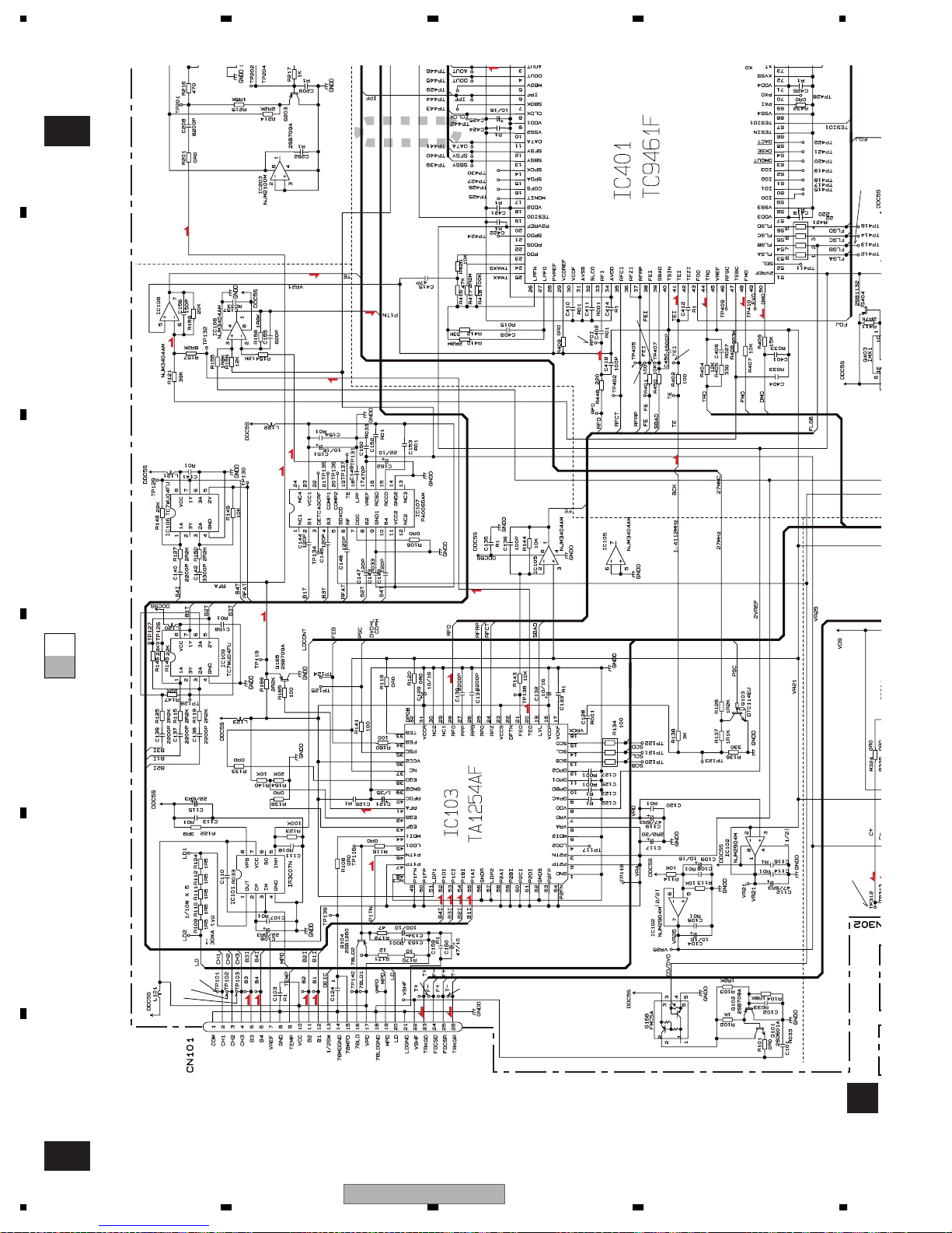
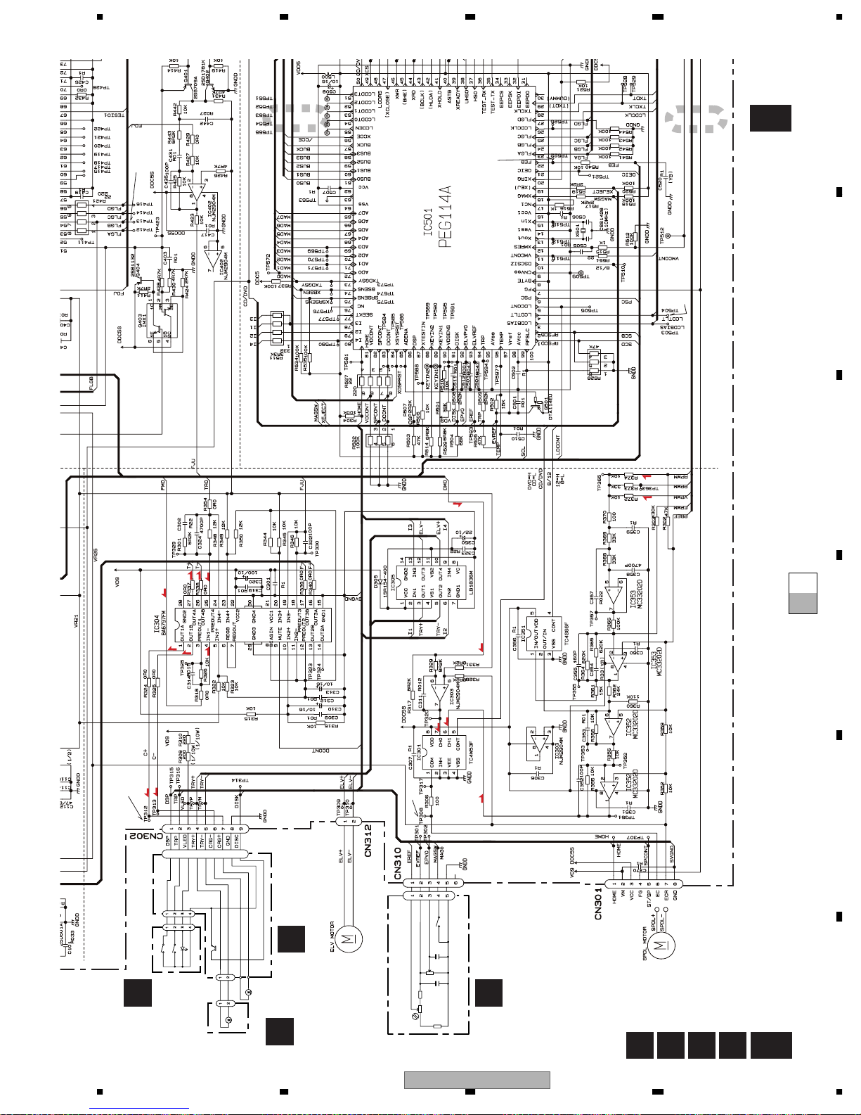
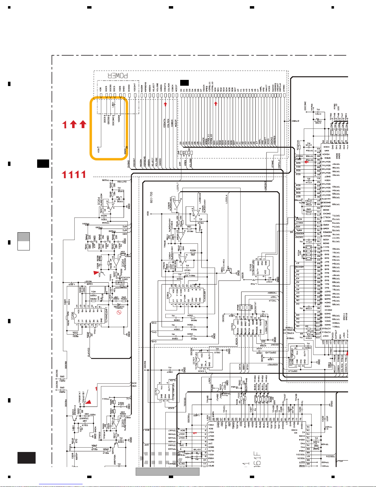
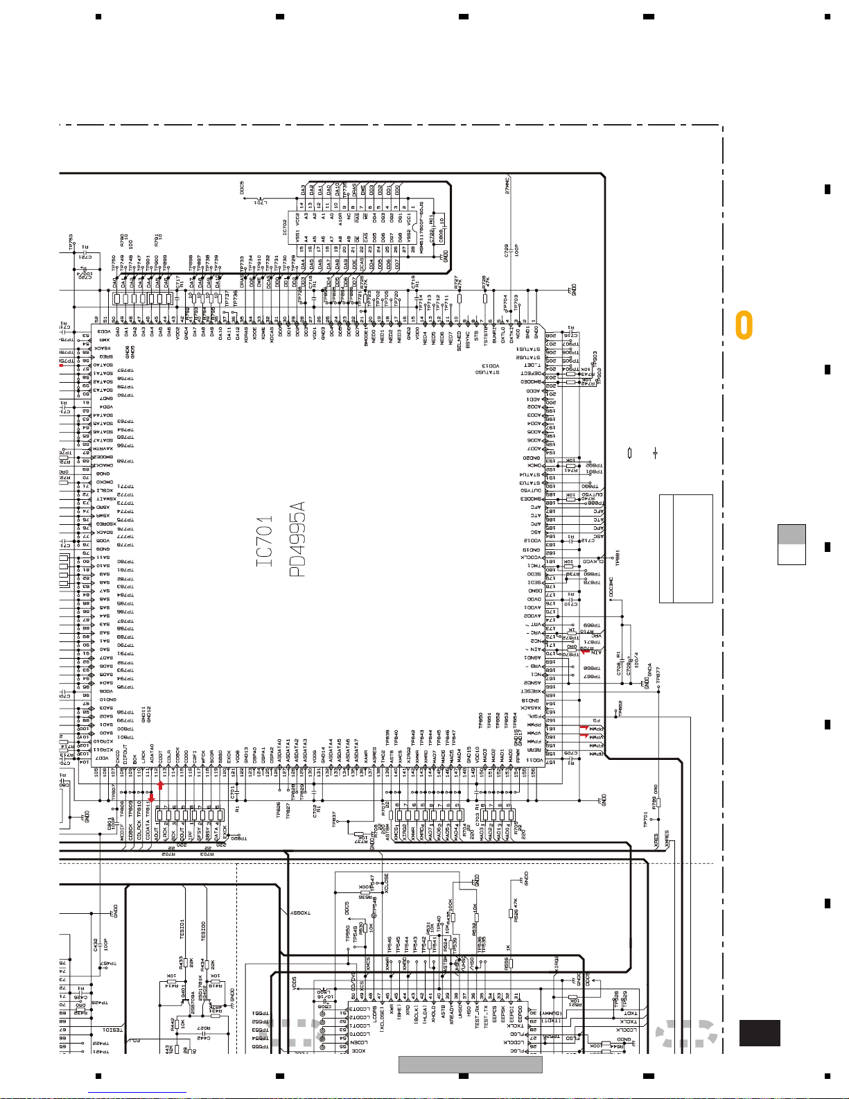
3.2 DVD/CD MECHANISM UNIT, MAIN PCB(SERVO SECTION)(GUIDE PAGE)
Note: When ordering service parts, be sure to refer to " EXPLODED VIEWS AND PARTS LIST" or
"ELECTRICAL PARTS LIST".
A
Large size
A-a A-b
SCH diagram
E-a
1/2
%
A-a
A-b
Guide page
A-b
Detailed page
PU UNIT
A-a
B
$
#
R
R
R
R
T
R(DVD)
T
3
T
2
R
R
R
R
R(DVD)
R(CD)
T
R(DVD)
T
T
T
R(DVD)
T
T
R
RF AMP
T
!
R(CD)
6
C
T
5
7
T
1
T
C
S(CD)
SERVO DSP
S(DVD)
8
C
C
C
4
S(CD)
S(DVD)
SPDL
C
C
C
S(CD)
T
T
T
S(CD)
S(DVD)
S(DVD)
MECHANISM
CONTROLLER
^
PCB UNIT(A)
A
DSP
S851
CSN1051
S852
CSN1052
D851
CN504-2
D
M2
CXC1541
TRAY
M1
CXC1552
CARRIAGE
PCB(B)
D
M4 CXC1540
VR302
CCP1338
R302
VR301
6R2K
CCW1021
10K
1K(B)
C301
R1
PCB UNIT(B)
B
C302
R01
CXM1282
R301
5R6K
E
TRP
C
M3
Q851
PT4800
MAG
CN301
S301
CSN1044
DSP
TRP
VLED
TRY+
TRY-
CRG-
CRG+
PCB(A)
EREF
EVREF
EPVO
MAGSW
GND0
GND
DISC
0
@
F
A B C D
16
1234
E
1/2
XDV-M8357ZT/UC
5678
SERVO DSP
RF EQUALIZER
ROM
R(DVD)
E-b
VCO
9
&
F
F.ACT DRIVEF.ACT DRIVE
T
T.ACT DRIVET.ACT DRIVE
R
RFRF
C
CRG DRIVECRG DRIVE
1/2
MAIN PCB(SERVO SECTION)
1/2
E
S
SPDL DRIVESPDL DRIVE
AUDIO
AUDIO(ANALOG) SIGNALAUDIO(ANALOG) SIGNAL
ROM
ROM DATA SIGNALROM DATA SIGNAL
B
A
LCD DRIVE
AUDIO
2/2
E
ROM
C
ISM
LER
ROM
0
F JUMP
AUDIO
ROM
D
DRAM
ASIC
@
S(DVD)
S(DVD)
R(DVD)
Main Unit
Consists of
Main PCB
Keyboard PCB
NOTE :
Symbol indicates a resistor.
No differentiation is made between chip resistors and
discrete resistors.
Symbol indicates a capacitor.
No differentiation is made between chip capacitors and
discrete capacitors.
The > mark found on some component parts indicates
the importance of the safety factor of the part.
Therefore, when replacing, be sure to use parts of
identical designation.
Decimal points for resistor
and capacitor fixed values
are expressed as :
←
2.2 2R2
←
0.022 R022
: The power supply is shown with the marked box.
E
F
56
XDV-M8357ZT/UC
1/2
E
7
8
17
Q
C
1234
ROM
A
B
C
E-b
1/2
RF E
1
SERVO DSP
R(DVD)
T
T
T
T
T
!
R(CD)
T
7
6
5
T
R(DVD)
T
C
S(CD)
1
0
T
E-b
A-a
E-a
D
R(DVD)
R(CD)
T
R(DVD)
RF AMP
T
RRR
R
E
#
$
%
R
R
R
R
3
T
2
T
C
8
F
E-a
1/2
18
1234
PU UNIT
PCB UNIT(A)
A
XDV-M8357ZT/UC
5678
A
2
3
E-b
1/2
0
@
MECHANISM
CONTROLLER
B
^
E-b
A-a
E-a
C
S(DVD)
S(CD)
T
T
T
C
S(DVD)
C
C
C
C
8
DSP
TRY+
TRP
VLED
TRP
DSP
D851
CN504-2
S852
CSN1052
S851
CSN1051
PCB UNIT(A)
A
C
S(CD)
S(CD)
S(DVD)
D
SPDL
4
Q851
PT4800
S(DVD)
GND
DISC
CRG+
CRG-
TRY-
EREF
EPVO
EVREF
GND0
CN301
VR301
CCW1021
R302
6R2K
VR302
CCP1338
MAGSW
S301
CSN1044
MAG
C302
R01
10K
R1
C301
1K(B)
R301
5R6K
PCB UNIT(B)
B
A B C D
M3
CXM1282
E-a
M2
CXC1541
TRAY
M1
CXC1552
CARRIAGE
PCB(A)
C
PCB(B)
D
M4 CXC1540
E
F
1/2
56
XDV-M8357ZT/UC
7
8
19
1234
A
2/2
E
AUDIO(ANALOG) SIGNALAUDIO(ANALOG) SIGNAL
B
SPDL DRIVESPDL DRIVE
S
ROM DATA SIGNALROM DATA SIGNAL
ROM
AUDIO
AUDIO
ROM
MAIN PCB(SERVO SECTION)
1/2
E
F.ACT DRIVEF.ACT DRIVE
F
C
E-b
E-a
D
CRG DRIVECRG DRIVE
RFRF
T.ACT DRIVET.ACT DRIVE
C
R
T
VCO
&
LCD DRIVE
ROM
E
9
R(DVD)
F
RF EQUALIZER
E-b
1/2
20
1234
1
XDV-M8357ZT/UC
ROM
F JUMP
DSP
ROM
5678
A
←
DRAM
←
Decimal points for resistor
and capacitor fixed values
are expressed as :
2.2 2R2
0.022 R022
B
: The power supply is shown with the marked box.
AUDIO
ROM
ASIC
S(DVD)
S(DVD)
Symbol indicates a resistor.
No differentiation is made between chip resistors and
discrete resistors.
Symbol indicates a capacitor.
No differentiation is made between chip capacitors and
discrete capacitors.
The > mark found on some component parts indicates
the importance of the safety factor of the part.
Therefore, when replacing, be sure to use parts of
NOTE :
R(DVD)
identical designation.
Main Unit
Consists of
Main PCB
Keyboard PCB
C
E-b
E-a
D
E
F JUMP
56
F
2
XDV-M8357ZT/UC
7
3
E-b
8
1/2
21
I
v
k
e
s
I
i
:
i
p
v
I
i
:
i
p
v
-
i
i
eck
e
i
-
i
i
eck
d
i
I
i
:
i
p
v
i
i
p
v
I
eck
e
I
V/di
/div
k
d
V/di
I
i
or
ocus close situatio
v
V/di
I
i
or
ocus close situatio
-
i
i
ocus close situation
i
v
ote:1.
.
ge
1234
N
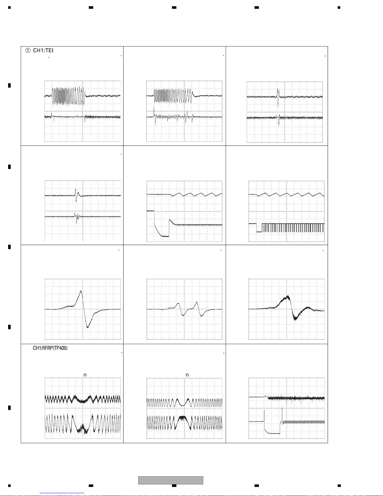
The encircled numbers denote measuring pointes in the circuit diagram
Reference volta
veform
A
-
DVD:32 tracks jum
h1 VR21
B
h2 VR21
H1:TE
H2
1V/d
2V/d
1V/d
2V/d
2ms/di
2ms/di
H1:TE
H2
D:32 tracks jum
h1 VR21
h2 VR21
H1:F
CH2:EC(TP308)1V/d
1V/d
2V/d
2V/d
2ms/di
500ms/d
DVD:S curve ch
CD:1 track jum
h1 VR21
C
Servo adjustment mod
h1 VR21
H1:TE
H2
1V/d
2V/d
DVD:1 track jum
h1 VR21
h2 VR21
H1:F
H2:EC(TP308)1V/d
D:S curve ch
Servo adjustment mo
h1 VR21
2V/d
s/di
500ms/d
h2 VR21
H1:FE
500mV/di2ms/div
DVD:S curve ch
Servo adjustment mod
D
h1 VR21
500m
H2:TE
E
D:RFRP wavef
1V/d
2ms/di
F
h1 VR21
h2 VR21
H1:FE
500mV/di2ms/di
2 layer DVD:S curve chec
Servo adjustment mod
h1 VR21
H1:RFRP(TP405)500m
H2:TE
1V/d
D:RFRP wavef
F
h1 VR21
5ms/di
h2 VR21
H1:FE
00m
D:S curve chec
Servo adjustment mo
h1 VR21
H1:F
1V/d
H2:EC(TP308)1V/d
DVD:F
2ms
500ms/d
h2 VR21
F
22
1234
h2 VR21
XDV-M8357ZT/UC
1 VR21
h2 VR21
I
)
ocus close
i
I
)
ocus close
)
i
i
de
de
v
i
i
)
v
i
i
de
de
v
-
i
V/di
ocus close
v
-
i
:
i
)
v
i
r
I
i
-
i
r
v
OI
i
i
r
-
i
:
i
)
v
OI
i
i
)
v
D
5678
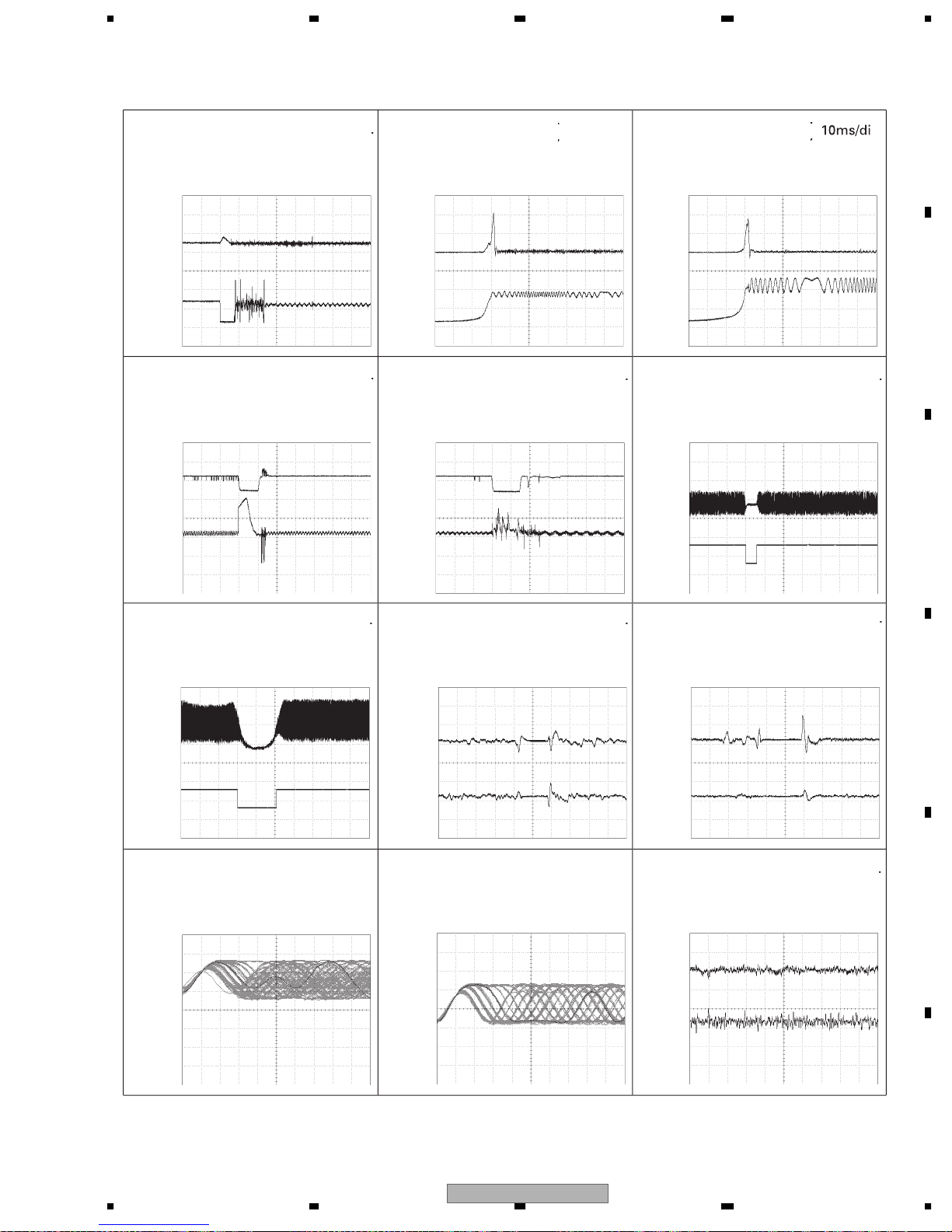
H1:F
H2:EC(TP308)1
D:f
h1 VR21
h2 VR21
H1:C-(TP313)2V/d
H2:EC(TP308)1V/d
DVD:CRG insi
h1 VR21
h2 VR21
1V/d
500m/di
i
s/di
H1:FE
H2:SBAD(TP407
DVD:f
h1 VR21
h2 VR21
H1:C-(TP313
H2:EC(TP308)1V/d
D:CRG insi
h1 VR21
h2 VR21
2V/d
i
.
10ms/d
.
500m/di
H1:FE
H2:SBAD(TP407
D:f
h1 VR21
h2 VR21
H1:Ain(TP210)1V/d
H2:FLGB(TP413)5V/d
DVD:passing black dot (1mm
h1 VR21
h2 VR21
.
A
.
B
s/di
C
H1:RF
1V/d
H2:FLGB(TP413)5V/d
CD:passing black dot (1mm
h1 VR21
h2 VR21
CH1:Ain(TP210)500mV/di100ns/d
DVD:during playback Ain wavefo
ch1 GN
s/di
H1:F
H2
DVD:passing black dot (1mm
h1 VR21
h2 VR21
H1:RF
1V/d
CD:during playback RFOI wavefo
h1 VR21
2V/d
2V/d
200s/di
500ns/d
H1:F
H2
2V/d
2V/d
500s/di
D:passing black dot (1mm
h1 VR21
h2 VR21
H1:FE
H2:F
200mV/d
1V/d
1ms/di
DVD:during playback FEI wavefo
h1 VR21
D
E
56
XDV-M8357ZT/UC
h2 VR21
F
7
8
23
I
)
t
I
i
:
i
r
v
I
i
I
i
p
v
I
i
I
i
p
i
I
)
t
i
I
i
I
i
p
i
I
i
-
i
r
v
I
)
t
i
i
01
i
02
i
03
V/di
o
v
01
:
o
V
i
CO
i
CO
I
V/di
:
i
r
v
D
D
D
D
D
D
D
D
D
D
D
D
1234
A
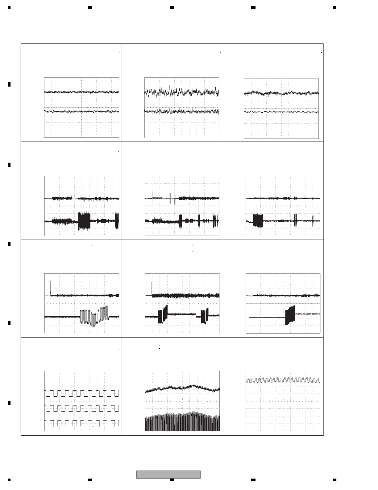
H1:FE
H2:F
CD:during playback FEI wavefo
h1 VR21
B
h2 VR21
H1:FE
CH2:TE
DVD:setu
ch1 GN
C
ch2 GN
200mV/d
1V/d
500mV/d
1V/d
1ms/di
s/di
H1:TE
H2
200mV/d
1V/d
1ms/di
DVD:during playback TEI wavefo
h1 VR21
h2 VR21
H1:FE
H2:TE
500mV/d
1V/d
2 layer DVD:setu
ch1 GN
ch2 GN
1s/d
H1:TE
H2
200m
1V/d
1ms/di
CD:during playback TEI wavefo
1 VR21
h2 VR21
H1:FE
H2:TE
500mV/d
1V/d
500ms/d
CD:setu
ch1 GN
ch2 GN
H1:FE
H2:FEB(TP522
.
500ms/d
.
DVD:focus balance adjustmen
D
h1 VR21
h2 VR21
H1:TP1
H2:TP1
H3:TP1
E
DVD:LCD tilt serv
ch1 GN
ch2 GN
5V/d
5V/d
5
1ms/di
H1:FE
H2:FEB(TP522
2 layer DVD:focus balance adjustmen
h1 VR21
h2 VR21
H1:TP1
H4
T(TP504)
DVD:LCD tilt serv
H1, CH4:offset voltage 2.5
ch1 GN
ch4 GN
.
500ms/d
.
.
1s/d
.
H1:FE
H2:FEB(TP522
CD:focus balance adjustmen
h1 VR21
h2 VR21
H1:V
500mV/di200ns/d
DVD:V
ch1 GN
.
500ms/d
.
ch3 GN
F
24
1234
XDV-M8357ZT/UC
i
v
t
D
5678
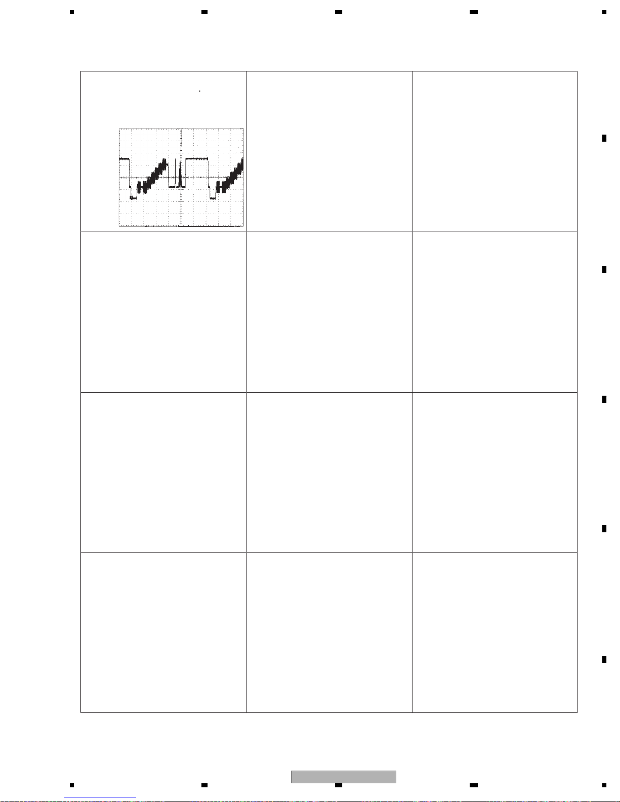
IC1201 pin 45200mV/d
10s/di
Composite signal outpu
ch1 GN
A
B
C
D
E
F
56
XDV-M8357ZT/UC
7
8
25
1234
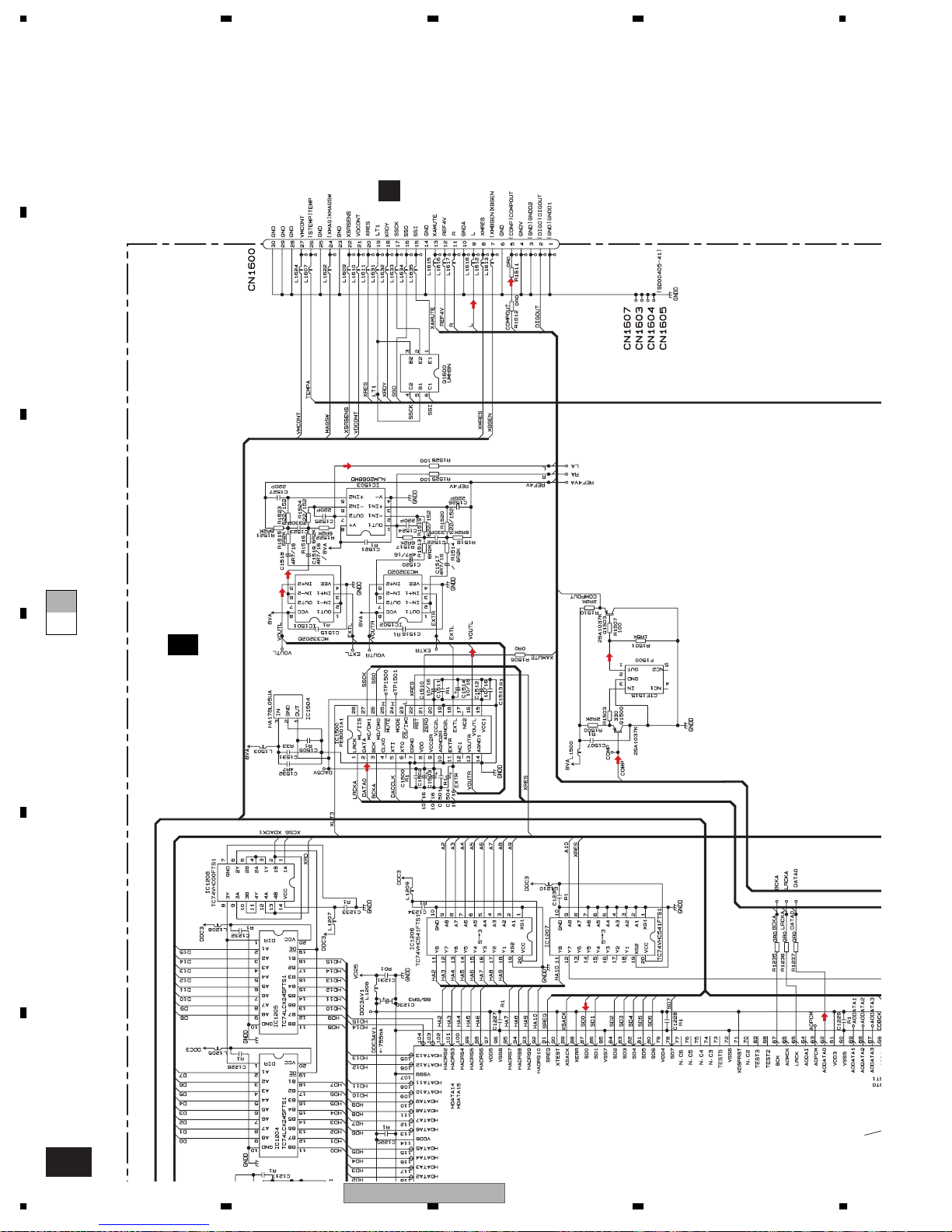
3.3 MAIN PCB(DECODER SECTION)(GUIDE PAGE)
A
E-a
2/2
B
C
D
1/2
E
ROM
MPEG DECODER
AU
**
VIDEO
E
F
2/2
E
26
1234
(PROGRAM)
XDV-M8357ZT/UC
5678
A
MAIN PCB(DECODER SECTION)
2/2
E
AU
AU
E-b
2/2
AU
AU
F
CN3961
AU
ROM
VIDEO
VIDEO
AU
VIDEO
B
C
AU
**
AU
VIDEO
D
56
Main Unit
Consists of
Main PCB
Keyboard PCB
ROM
ROM DATA SIGNALROM DATA SIGNAL
VIDEO
VIDEO SIGNAL(COMPOSITE)VIDEO SIGNAL(COMPOSITE)
AU
AUDIO SIGNALAUDIO SIGNAL
AU(D)
AUDIO SIGNAL(DIGITAL)AUDIO SIGNAL(DIGITAL)
XDV-M8357ZT/UC
F
CN3951
E
F
2/2
E
7
8
27
1234
A
B
C
E-b
**
2/2
MPEG DECODER
E-b
A-a
E-a
D
E
ROM
AU
1/2
E
F
E-a
2/2
28
1234
XDV-M8357ZT/UC
5678
VIDEO
**
A
21
E-b
2/2
B
C
(PROGRAM)
E-b
A-a
E-a
D
E
56
XDV-M8357ZT/UC
F
E-a
2/2
7
8
29
1234
A
F
CN3961
VIDEO
B
AU
AU
C
E-b
E-a
MAIN PCB(DECODER SECTION)
2/2
E
D
AU
AU
AU
AU
VIDEO
VIDEO
E
F
E-b
2/2
30
1234
ROM
AU
**
XDV-M8357ZT/UC
 Loading...