

Pioneer XDV-M8137ZT/UC, XDV-M8137ZT-91/UC Service Manual
ORDER NO.
CRT3131
PUB. NO. CRT3131
AUDIO SYSTEM
DVD/CD COMPATIBLE
CHANGER
Manufactured for TOYOTA
by PIONEER CORPORATION
VEHICLE DESTINATION PRODUCED AFTER TOYOTA PART No. ID No. PIONEER MODEL No.
LEXUS LX470 U.S.A., CANADA August 2003 86270-60112 XDV-M8137ZT/UC
XDV-M8137ZT-91/UC
LX470
7
Q
Q
TEL 13942296513 QQ 376315150 892498299
3
6
3
1
5
1
5
0
8
9
2
4
9
2
8
9
9
TEL 13942296513 QQ 376315150 892498299
TEL
13942296513
Q
Q
3
7
6
3
1
5
1
5
0
8
9
9
4
2
8
2
9
9
w
w
w
.
xia
o
y
u
1
6
3
.
c
o
m
2
1
234
12
34
F
E
D
C
B
A
XDV-M8137ZT/UC
Model No. Order No. Mech. Module Remarks
XDV-M8106ZT/UC CRT2537
CX-692 CRT2533 MM-1 DVD/CD Mech. Unit:Circuit Description, Mech.Description, Disassembly
- This service manual should be used together with the manual(s) listed below.
For the parts numbers, adjustments, etc. which are not shown in this manual, refer to the following
manual(s).
- The supplementary models are identical with the original ones except for the following items.
XDV-M8137ZT-91/UC
Description Part No.
Polyethylene Bag CEG1181
Air Cap CEG1288(Non Spare Part)
Carton CHG4170
Contain Box(1/2) CHL5166
Protector CHP2341(TOP)
Protector CHP2342(BOTTOM)
Q
Q
For details, refer to "Important symbols for good services".
TEL 13942296513 QQ 376315150 892498299
TEL
7
3
13942296513
6
3
1
5
1
5
0
Q
Q
3
7
6
8
3
9
1
5
1
2
5
4
0
9
8
9
8
2
4
2
9
8
9
2
9
9
TEL 13942296513 QQ 376315150 892498299
9
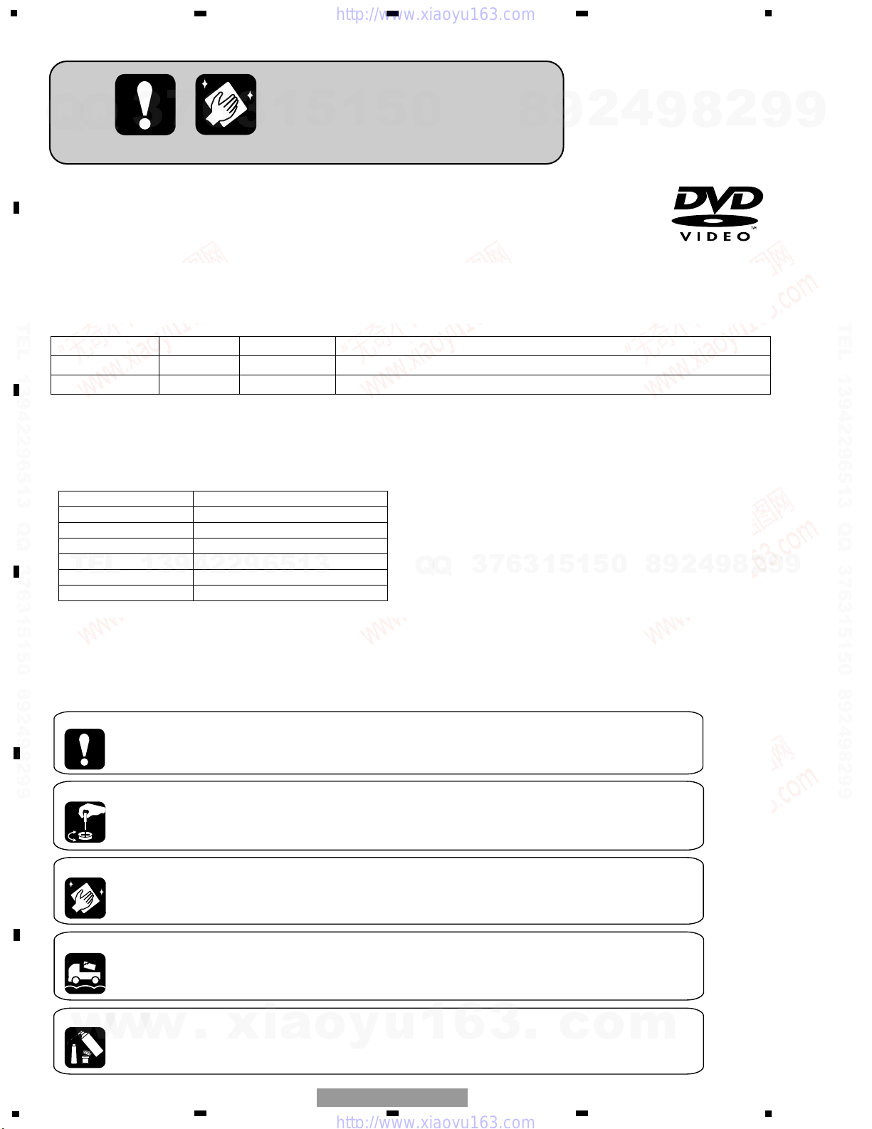
[ Important symbols for good services ]
In this manual, the symbols shown-below indicate that adjustments, settings or cleaning should be made securely.
When you find the procedures bearing any of the symbols, be sure to fulfill them:
1. Product safety
You should conform to the regulations governing the product (safety, radio and noise, and other regulations), and
should keep the safety during servicing by following the safety instructions described in this manual.
2. Adjustments
To keep the original performances of the product, optimum adjustments or specification confirmation is indispensable.
In accordance with the procedures or instructions described in this manual, adjustments should be performed.
3. Cleaning
For optical pickups, tape-deck heads, lenses and mirrors used in projection monitors, and other parts requiring cleaning,
proper cleaning should be performed to restore their performances.
4. Shipping mode and shipping screws
To protect the product from damages or failures that may be caused during transit, the shipping mode should be set or
the shipping screws should be installed before shipping out in accordance with this manual, if necessary.
5. Lubricants, glues, and replacement parts
Appropriately applying grease or glue can maintain the product performances. But improper lubrication or applying
w
w
w
glue may lead to failures or troubles in the product. By following the instructions in this manual, be sure to apply the
prescribed grease or glue to proper portions by the appropriate amount.For replacement parts or tools, the prescribed
ones should be used.
.
xia
o
y
u
1
6
3
.
c
o
m
3
5
6
7
8
F
E
D
C
B
A
5
6
7
8
XDV-M8137ZT/UC
ELECTRICAL PARTS LIST(Page 48)
EXTENSION UNIT
Part No.
Symbol and Description XDV-M8106ZT/UC XDV-M8137ZT/UC
IC 3601 IC PE5058B PE5377A
R 3607 RS1/16S104J RS1/16S102J
Q
TEL 13942296513 QQ 376315150 892498299
Q
3
7
6
3
1
5
1
5
0
8
9
2
4
9
8
2
9
9
TEL 13942296513 QQ 376315150 892498299
TEL
13942296513
Q
Q
3
7
6
3
1
5
1
5
0
8
9
2
4
9
8
2
9
9
w
w
w
.
xia
o
y
u
1
6
3
.
c
o
m
4
1
234
12
34
F
E
D
C
B
A
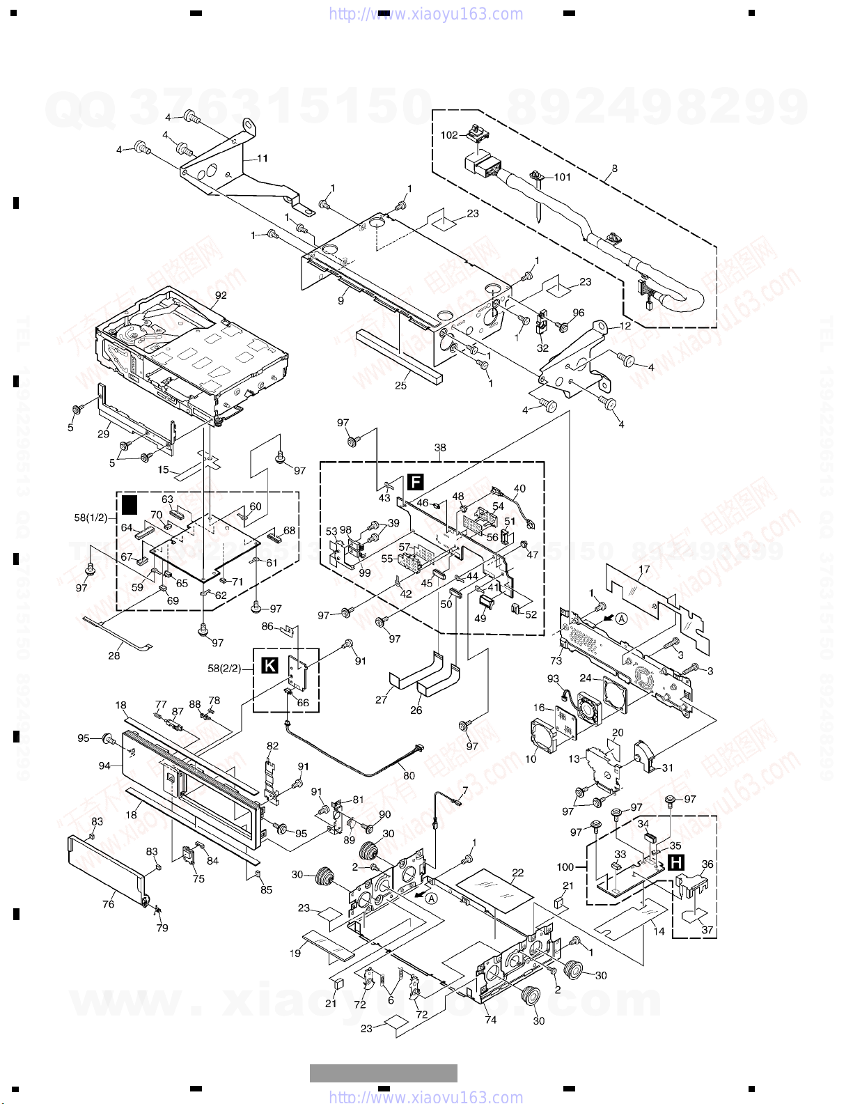
XDV-M8137ZT/UC
EXPLODED VIEWS AND PARTS LIST
EXTERIOR
E
F
Q
Q
TEL 13942296513 QQ 376315150 892498299
3
7
6
3
1
5
1
5
0
8
9
2
4
9
8
2
9
9
TEL 13942296513 QQ 376315150 892498299
TEL
13942296513
Q
Q
3
7
6
3
1
5
1
5
0
8
9
2
4
9
8
2
9
9
w
w
w
.
xia
o
y
u
1
6
3
.
c
o
m
5
5
6
7
8
F
E
D
C
B
A
5
6
7
8
XDV-M8137ZT/UC
1 Screw BSZ30P055FMC
2 Screw(M2x2) CBA1176
3 Screw(M3x12) CBA1514
4 Screw(M5x6) CBA1517
5 Screw(M2x3.5) CBA1532
6 Spring CBH2335
7 Connector CDE6302
8 Cord Assy CDE6983
9 Upper Case CNB2496
10 Holder CNC8612
11 Bracket CNC8831
12 Bracket CNC8832
13 Shield CNC9089
14 Insulator CNM6337
15 Insulator CNM6405
16 Filter CNM6600
17 Insulator CNM6735
18 Cushion CNM6743
* 19 Insulator CNM6906
20 Insulator CNM6985
21 Cushion CNM7037
* 22 Insulator CNM7090
* 23 Tape CNM7273
24 Cushion CNM7347
25 Cushion CNM7872
26 PCB CNP5534
27 PCB CNP5535
28 PCB CNP5604
29 Panel CNS6473
30 Damper CNV5833
31 Holder CNV6181
32 Holder CNV6245
33 Plug(CN2903) CKS1051
34 Connector(CN2901) CKS3563
35 Holder CNC2218
36 Shield CNC8898
37 Insulator CNM6836
38 Extension Unit CWM9095
39 Screw BMZ26P050FMC
40 Cord CDE6446
41 Terminal(CN3810) CKF1064
42 Terminal(CN3811) CKF1064
43 Terminal(CN3812) CKF1064
44 Terminal(CN3813) CKF1064
45 Connector(CN3951) CKS1953
46 Connector(CN3891) CKS2191
47 Connector(CN3301) CKS2619
48 Connector(CN3302) CKS2619
49 Plug(CN3802) CKS3535
50 Connector(CN3961) CKS3749
51 Connector(CN3801) CKS4320
52 Connector(CN3803) CKS4356
53 Holder CNC8400
54 Shield CNC8899
55 Shield CNC8900
56 Insulator CNM6834
57 Insulator CNM6835
58 Main Unit CWM9093
59 Terminal(CN1603) CKF1064
60 Terminal(CN1604) CKF1064
61 Terminal(CN1605) CKF1064
62 Terminal(CN1607) CKF1064
63 Connector(CN1601) CKS1953
64 Connector(CN101) CKS1964
65 Connector(CN312) CKS2191
66 Connector(CN2000) CKS2193
67 Connector(CN302) CKS3480
68 Connector(CN1600) CKS3749
69 Connector(CN310) CKS3767
70 Connector(CN301) CKS4358
71 Connector(CN1000) CKS4374
72 Arm Unit CXA8606
73 Rear Frame Unit CXB6364
74 Lower Case Unit CXB6365
75 Button(EJECT) CAC6152
76 Door CAT2385
77 Spring CBH2336
78 Spring CBH2337
79 Spring CBH2363
80 Connector CDE6022
81 Holder CNC8402
82 Holder CNC8409
83 Cushion CNM6407
84 Cushion CNM6842
85 Cushion CNM6843
* 86 Insulator CNM6907
87 Lever CNV5831
88 Lever CNV6104
89 Damper Unit CXB4206
90 Screw IMS20P035FZK
91 Screw IMS26P040FMC
92 DVD/CD Mechanism Unit(MM-1) CXK7020
93 Fan Motor CXM1195
94 Grille CNS6472
95 Screw IMS30P060FZK
96 Screw ISS30P060FMC
97 Screw PMB26P050FMC
98 IC(IC3821) BA00AST
99 Transistor(Q3811) 2SB942A
100 MF Unit CWM6518
101 Clamper CNV7278
102 Clamper CNV7279
Mark No. Description Part No. Mark No. Description Part No.
- EXTERIOR SECTION PARTS LIST
NOTE:
- Parts marked by “*” are generally unavailable because they are not in our Master Spare Parts List.
- Screws adjacent to ∇ mark on the product are used for disassembly.
- For the applying amount of lubricants or glue, follow the instructions in this manual.
( In the case of no amount instructions, apply as you think it appropriate.)
Q
1
5
0
8
Q
7
3
6
3
1
5
9
2
4
9
8
2
9
9
TEL 13942296513 QQ 376315150 892498299
TEL
13942296513
Q
Q
3
7
1
3
6
5
1
5
0
8
9
2
4
9
8
2
9
TEL 13942296513 QQ 376315150 892498299
9
w
w
w
.
xia
o
y
u
1
6
3
.
c
o
m
6
1
2
3
4 5
M3
CXM1178
SPINDLE
EREF
EVREF
EPVO
MAGSW
GND0
S301
CSN1044
MAG
C302
R01
VR301
CCW1021
C301
R1
R302
6R2K
VR302
CCP1338
1KΩ(B)
10K
R301
5R6K
CN301
M4
CXB3931
ELEVATION
DSP
TRP
VLED
TRY+
TRY-
CRG-
CRG+
GND
DISC
D851
CN504-2
S851
CSN1051
DSP
S852
CSN1052
TRP
M1
CXB3930
CARRIAGE
M2
CXB3932
TRAY
Q851
PT4800
PU UNIT
A
PCB UNIT(A)
C
PCB(A)
D
PCB(B)
B
PCB UNIT(B)
CD SPDL
DVD SPDL
5V
9V
R
R
R
R
R
R
R
R
R(CD)
R(CD)
R(CD)
R(DVD)
R(DVD)
R(DVD)
R(DVD)
T
T
T
T
T
T
T
T
T
T
T
T
T
T
T
T
T
T
T
T
T
T
T
C
C
C
C
C
C
C
C
S(CD)
S(CD)
S(CD)
S(CD)
S(DVD)
S(CD)
S(DVD)
S(DVD)
S(DVD)
S(DVD)
8
4
^
@
0
2
3
#
$
%
!
7
5
6
1
1
234
12
34
F
E
D
C
B
A
XDV-M8137ZT/UC
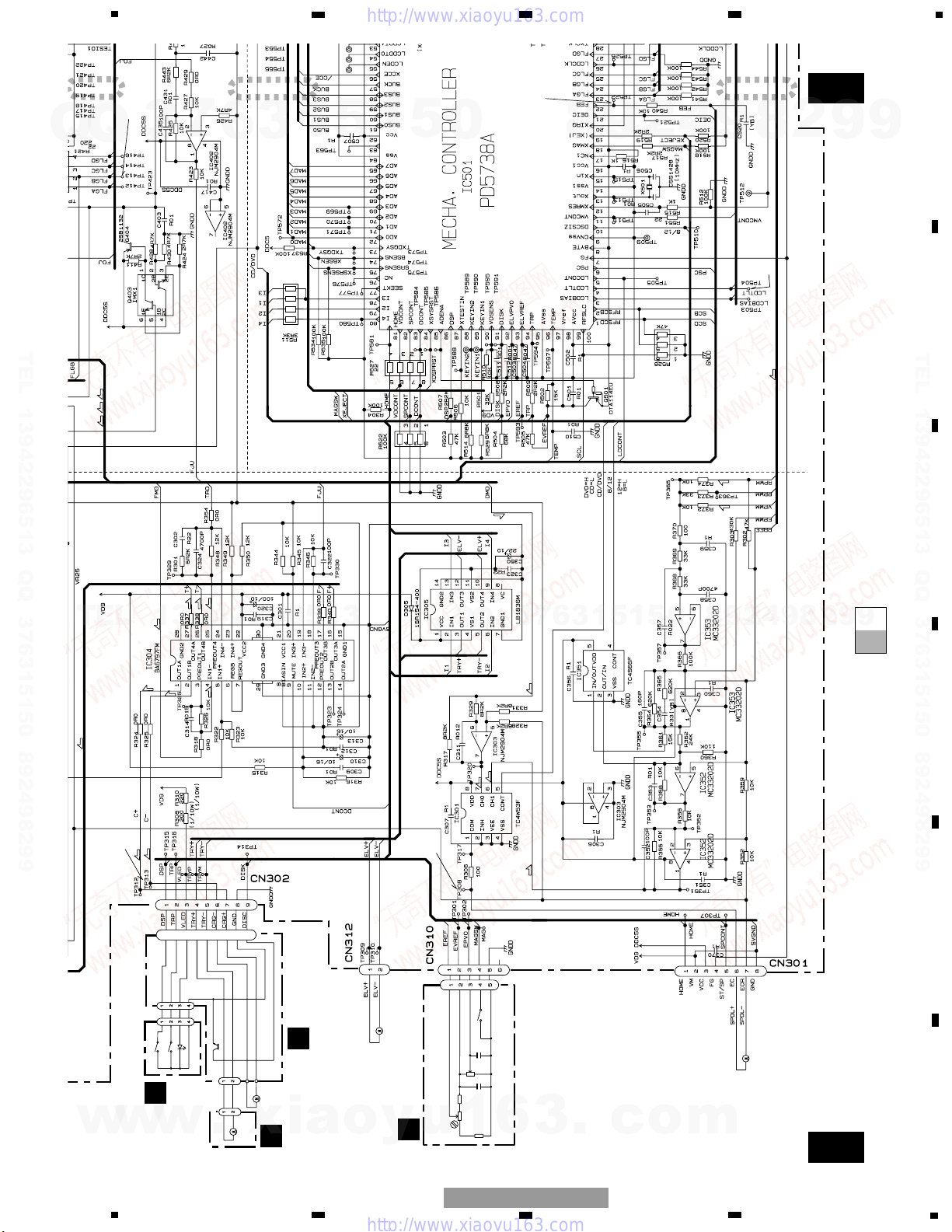
SCHEMATIC DIAGRAM
DVD MECHANISM UNIT, MAIN PCB(SERVO SECTION)(GUIDE PAGE)
Note: When ordering service parts, be sure to refer to “EXPLODED VIEWS AND PARTS LIST” or “ELECTRICAL
PARTS LIST”.
A-a
A-b
A-b
A-a
E
F 1/2
E-a
F 1/2
Q
Q
Large size
A-a A-b
SCH diagram
3
7
6
3
1
5
1
5
0
8
9
2
4
9
8
2
9
9
3
Q
Q
A-a
A-b
Guide page
A-a
TEL 13942296513 QQ 376315150 892498299
TEL
Detailed page
A-b
13942296513
7
6
3
1
5
1
5
0
8
TEL 13942296513 QQ 376315150 892498299
2
9
4
9
8
2
9
9
o
w
w
w
.
xia
y
u
1
6
3
.
c
o
m
7
LC89170MP
E
F 2/2
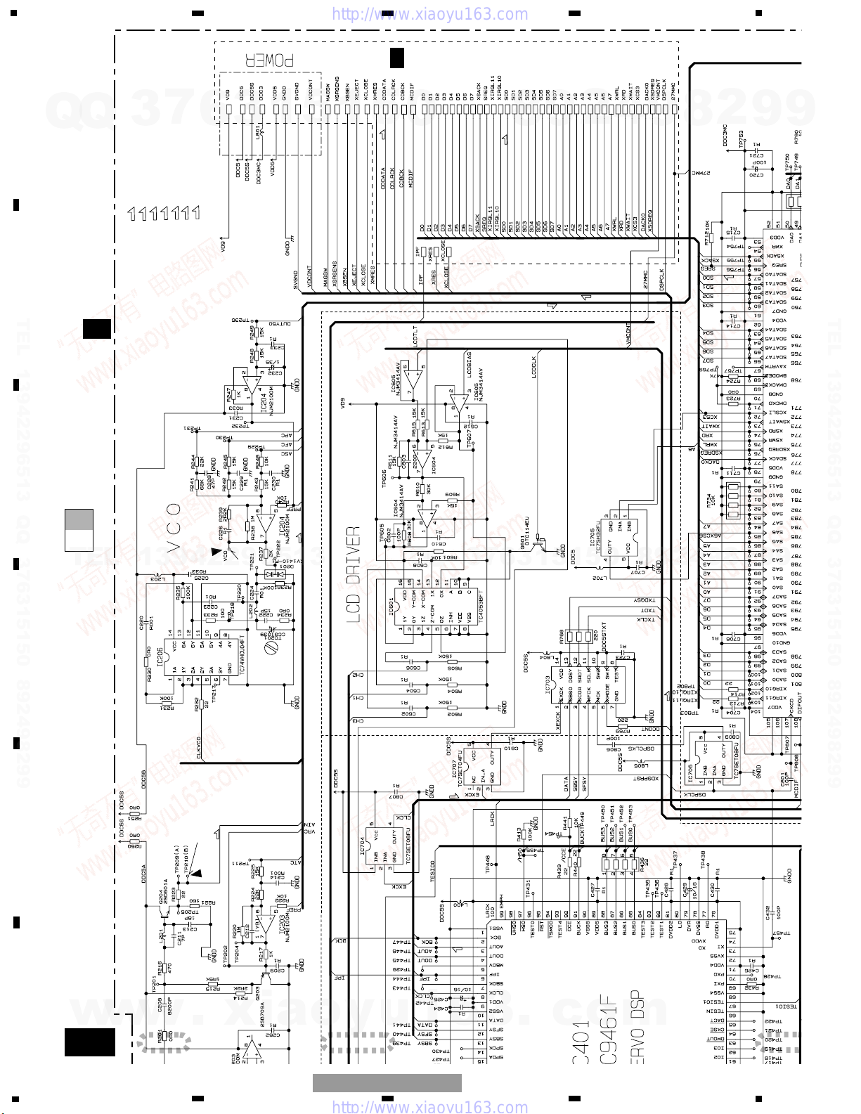
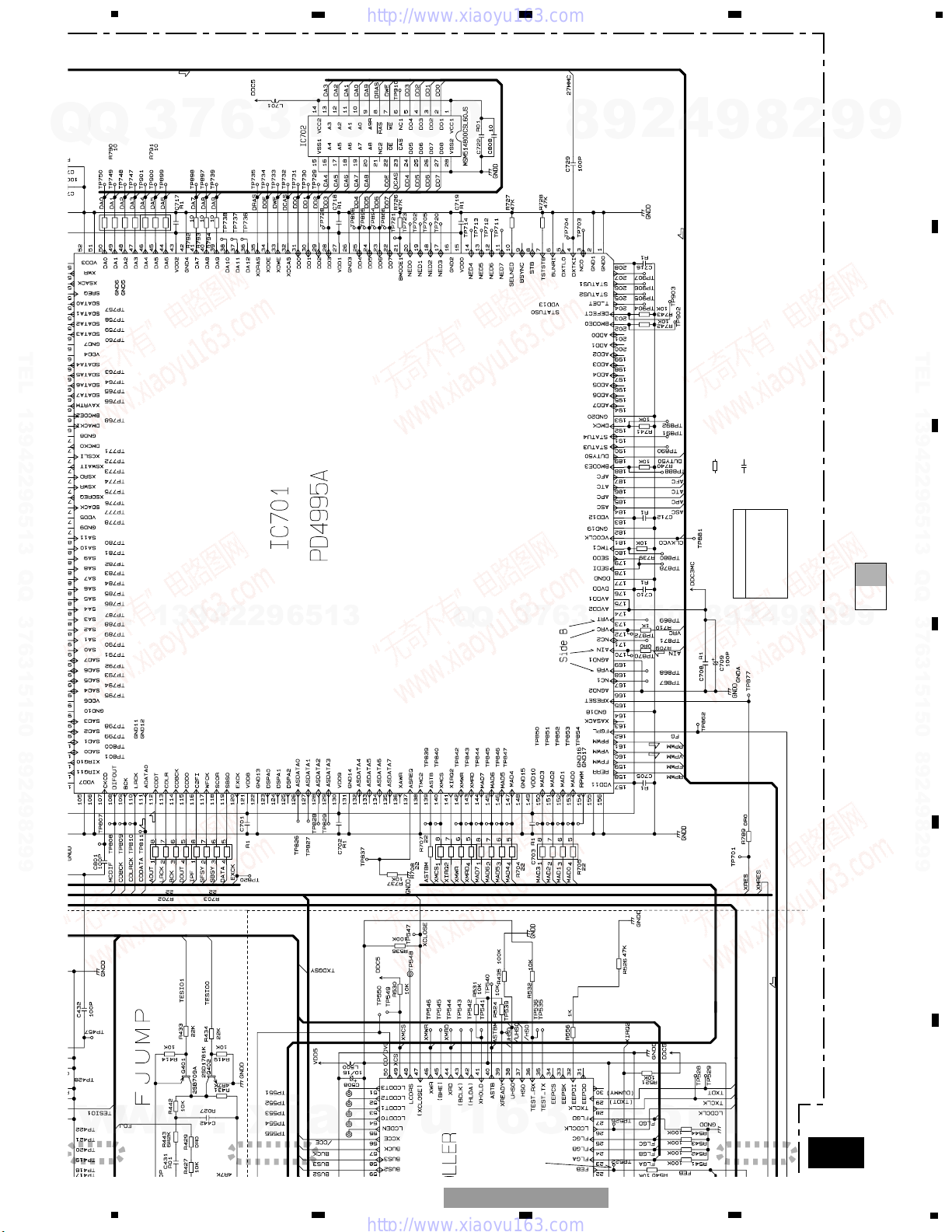
MAIN PCB (DECODER SECTION)
E
F 1/2
MAIN PCB (SERVO SECTION)
RF EQUALIZER
ASIC
DRAM
5V
3.3V
Decimal points for resistor
and capacitor fixed values
are expressed as :
2.2 2R2
0.022 R022
←
←
The > mark found on some component parts indicates
the importance of the safety factor of the part.
Therefore, when replacing, be sure to use parts of
identical designation.
Symbol indicates a resistor.
No differentiation is made between chip resistors and
discrete resistors.
NOTE :
Symbol indicates a capacitor.
No differentiation is made between chip capacitors and
discrete capacitors.
Main Unit
Consists of
Main PCB
Grille PCB
R(DVD)
R(DVD)
R(DVD)
R(DVD)
R(DVD)
R(DVD)
F
S(DVD)
S(DVD)
S(DVD)
ROM
ROM
ROM
ROM
ROM
AUDIO
AUDIO
AUDIO
AUDIO
F.ACT DRIVE
T
T.ACT DRIVE
R
RF
C
CRG DRIVE
S
SPDL DRIVE
AUDIO
AUDIO(ANALOG) SIGNAL
ROM
ROM DATA SIGNAL
&
9
5
6
7
8
F
E
D
C
B
A
5
6
7
8
XDV-M8137ZT/UC
E
F 1/2
E-b
F 1/2
7
3
Q
Q
TEL 13942296513 QQ 376315150 892498299
6
3
1
5
1
5
0
4
2
9
8
2
8
9
9
9
TEL 13942296513 QQ 376315150 892498299
TEL
13942296513
Q
Q
3
6
7
3
1
5
1
5
0
8
9
2
4
9
8
2
9
9
w
w
w
.
xia
y
u
1
6
o
3
.
c
o
m
8
A-a
E-b
E-a
E-a
E-b
1
2
3
PU UNIT
5V
9V
F
F
1/2
1/2
R
R
R
R
RRR
R
R(CD)
R(CD)
R(CD)
R(DVD)
R(DVD)
R(DVD)
R(DVD)
T
T
T
T
T
T
T
T
T
T
T
T
T
T
T
T
T
T
T
T
C
C
S(CD)
S(CD)
8
2
3
#
$
%
!
7
5
6
1
1
234
12
34
F
E
D
C
B
A
XDV-M8137ZT/UC
Q
TEL 13942296513 QQ 376315150 892498299
Q
3
7
6
3
1
5
1
5
0
8
9
2
4
9
8
2
9
9
TEL 13942296513 QQ 376315150 892498299
9
9
2
8
9
4
2
9
8
0
5
1
5
1
3
6
7
3
Q
Q
TEL
13942296513
w
w
w
.
xia
o
y
u
1
6
3
.
c
o
m
9
A-a
E-b
E-a
E-a
E-b
3
4 5
M3
CXM1178
SPINDLE
EREF
EVREF
EPVO
MAGSW
GND0
S301
CSN1044
MAG
C302
R01
VR301
CCW1021
C301
R1
R302
6R2K
VR302
CCP1338
1KΩ(B)
10K
R301
5R6K
CN301
M4
CXB3931
ELEVATION
DSP
TRP
VLED
TRY+
TRY-
CRG-
CRG+
GND
DISC
D851
CN504-2
S851
CSN1051
DSP
S852
CSN1052
TRP
M1
CXB3930
CARRIAGE
M2
CXB3932
TRAY
Q851
PT4800
A
PCB UNIT(A)
C
PCB(A)
D
PCB(B)
B
PCB UNIT(B)
CD SPDL
DVD SPDL
9V
F
F
1/2
1/2
T
T
T
T
T
C
C
C
C
C
C
C
S(CD)
S(CD)
S(CD)
S(DVD)
S(CD)
S(DVD)
S(DVD)
S(DVD)
S(DVD)
8
4
^
@
0
5
6
7
8
F
E
D
C
B
A
5
6
7
8
XDV-M8137ZT/UC
7
Q
TEL 13942296513 QQ 376315150 892498299
Q
3
6
3
1
5
1
5
0
8
9
2
4
9
8
2
9
9
TEL 13942296513 QQ 376315150 892498299
TEL
w
13942296513
w
.
xia
w
o
3
6
7
3
Q
Q
y
u
1
6
3
.
1
1
5
c
0
5
o
9
8
m
4
2
9
8
2
9
9
10
E-a
E-b
E-b
1
2
3
LC89170MP
E
F 2/2
MAIN PCB (DECODER SECTION)
E
F 1/2
MAIN PCB (SERVO SECTION)
RF EQUALIZER
5V
3.3V
F
1/2
R(DVD)
R(DVD)
R(DVD)
F
ROM
ROM
ROM
ROM
AUDIO
AUDIO
AUDIO
F.ACT DRIVE
T
T.ACT DRIVE
R
RF
C
CRG DRIVE
S
SPDL DRIVE
AUDIO
AUDIO(ANALOG) SIGNAL
ROM
ROM DATA SIGNAL
&
9
1
234
12
34
F
E
D
C
B
A
XDV-M8137ZT/UC
Q
Q
3
7
6
3
1
5
1
5
0
8
9
2
4
9
8
2
9
9
TEL 13942296513 QQ 376315150 892498299
TEL
13942296513
Q
Q
3
7
6
3
1
5
1
5
0
8
9
2
4
9
8
2
9
TEL 13942296513 QQ 376315150 892498299
9
w
w
w
.
xia
o
y
u
1
6
3
.
c
o
m
11
E-a
E-b
E-b
3
4 5
ASIC
DRAM
Decimal points for resistor
and capacitor fixed values
are expressed as :
2.2 2R2
0.022 R022
←
←
The > mark found on some component parts indicates
the importance of the safety factor of the part.
Therefore, when replacing, be sure to use parts of
identical designation.
Symbol indicates a resistor.
No differentiation is made between chip resistors and
discrete resistors.
NOTE :
Symbol indicates a capacitor.
No differentiation is made between chip capacitors and
discrete capacitors.
F
1/2
Main Unit
Consists of
Main PCB
Grille PCB
R(DVD)
R(DVD)
R(DVD)
S(DVD)
S(DVD)
S(DVD)
ROM
AUDIO
@
5
6
7
8
F
E
D
C
B
A
5
6
7
8
XDV-M8137ZT/UC
Q
TEL 13942296513 QQ 376315150 892498299
Q
3
7
6
3
1
5
1
5
0
8
9
4
2
9
8
2
9
9
TEL 13942296513 QQ 376315150 892498299
TEL
13942296513
Q
Q
3
7
6
3
1
5
1
5
0
9
8
2
4
9
8
2
9
9
w
w
w
.
xia
o
y
u
1
6
3
.
c
o
m
12
1
234
12
34
F
E
D
C
B
A
XDV-M8137ZT/UC
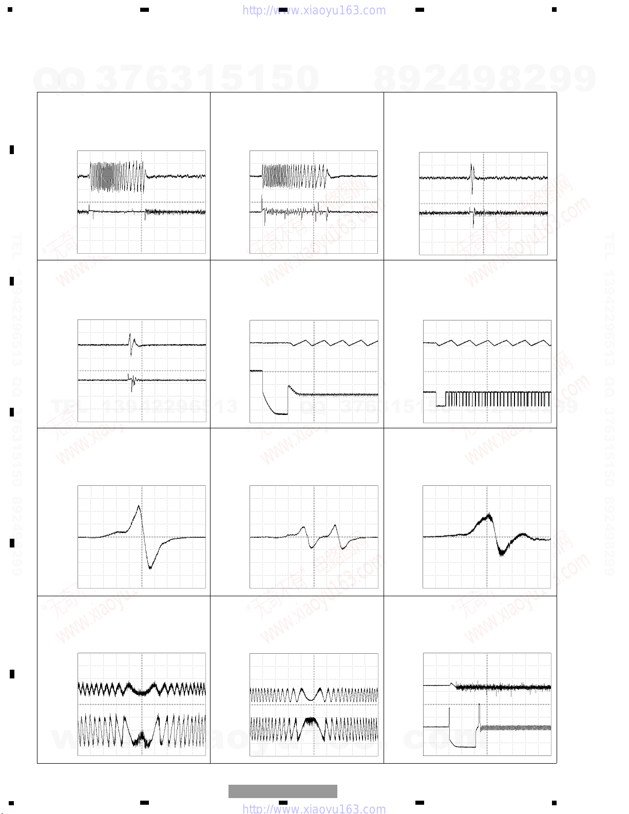
5 CH1:FEI 500mV/div. 2ms/div.
2 layer DVD:S curve check
Servo adjustment mode
- Waveforms
1 CH1:TEI 1V/div.
2 CH2:T- 2V/div.
CD:32 tracks jump
2ms/div.
1 CH1:TEI 1V/div.
2 CH2:T- 2V/div.
DVD:1 track jump
2ms/div.
3 CH1:F- 2V/div.
4 CH2:EC(TP308) 1V/div.
DVD:S curve check
Servo adjustment mode
500ms/div.
3 CH1:F- 2V/div.
4 CH2:EC(TP308) 1V/div.
CD:S curve check
Servo adjustment mode
500ms/div.
1 CH1:TEI 1V/div.
2 CH2:T- 2V/div.
CD:1 track jump
2ms/div.
1 CH1:TEI 1V/div.
2 CH2:T- 2V/div.
DVD:32 tracks jump
2ms/div.
5 CH1:FEI 500mV/div. 2ms/div.
DVD:S curve check
Servo adjustment mode
5 CH1:FEI 500mV/div. 2ms/div.
CD:S curve check
Servo adjustment mode
6
CH1:RFRP(TP405)
500mV/div.
1
CH2:TEI
1V/div.
CD:RFRP waveform
Focus close situation
2ms/div.
6 CH1:
RFRP(TP405)
500mV/div.
1 CH2:TEI 1V/div.
CD:RFRP waveform
Focus close situation
3 CH1:F- 1V/div.
4 CH2:
EC(TP308)
1V/div.
DVD:Focus close situation
500ms/div.
5ms/div.
ch1 VR21
→
ch2 VR21
→
ch1 VR21
→
ch2 VR21
→
ch1 VR21
→
ch2 VR21
→
ch1 VR21
→
ch2 VR21
→
ch1 VR21
→
ch2 VR21
→
ch1 VR21
→
ch2 VR21
→
ch1 VR21
→
ch1 VR21
→
ch1 VR21
→
ch1 VR21
→
ch2 VR21
→
ch1 VR21
→
ch2 VR21
→
ch1 VR21
→
ch2 VR21
→
Note:1. The encircled numbers denote measuring pointes in the circuit diagram.
2. Reference voltage
VR21:2.1V
Q
7
Q
3
6
1
3
5
1
5
0
8
4
2
9
9
8
2
9
9
TEL 13942296513 QQ 376315150 892498299
TEL
13942296513
Q
Q
3
7
9
8
0
5
1
5
1
3
6
4
2
9
8
2
9
TEL 13942296513 QQ 376315150 892498299
9
w
w
w
.
xia
o
y
u
1
6
3
.
c
o
m
 Loading...