

Page 1
2013
XDJ-R1
DJ SYSTEM
XDJ-R1
THIS MANUAL IS APPLICABLE TO THE FOLLOWING MODEL(S) AND TYPE(S).
Model Type Power Requirement Remarks
XDJ-R1 SVWYXE8 AC 220 V to 240 V
XDJ-R1 CUXE AC 120 V
XDJ-R1 FLWPWXE AC 110 V to 120 V or 220 V to 240 V
XDJ-R1 KXE5 AC 220 V
XDJ-R1 AXE5 AC 220 V to 240 V
ORDER NO.
RRV4401
PIONEER CORPORATION 1-1, Shin-ogura, Saiwai-ku, Kawasaki-shi, Kanagawa 212-0031, Japan
PIONEER ELECTRONICS (USA) INC. P.O. Box 1760, Long Beach, CA 90801-1760, U.S.A.
PIONEER EUROPE NV Haven 1087, Keetberglaan 1, 9120 Melsele, Belgium
PIONEER ELECTRONICS ASIACENTRE PTE. LTD. 253 Alexandra Road, #04-01, Singapore 159936
PIONEER CORPORATION
K-MZV JUNE
2013 Printed in Japan
Page 2
1
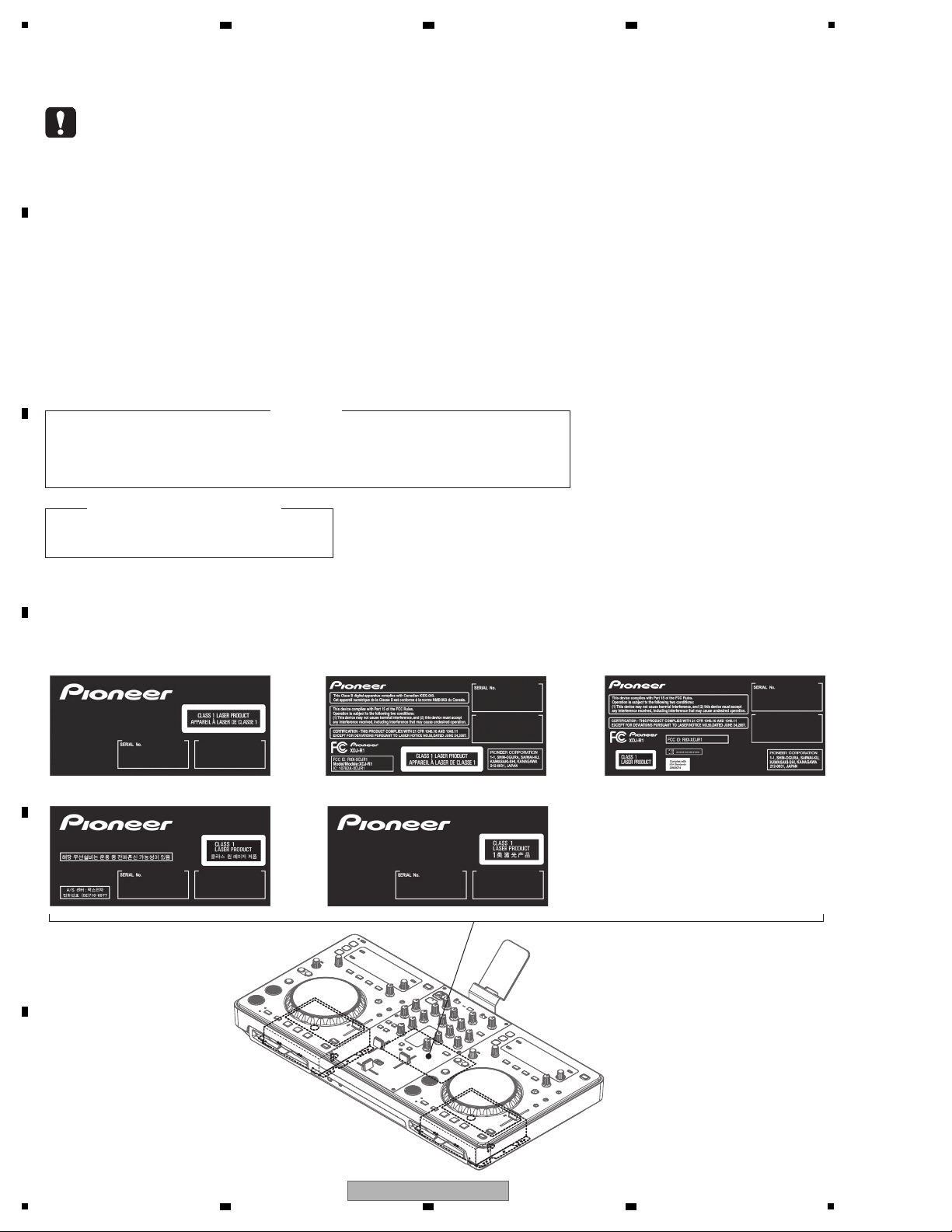
LABEL CHECK
WARNING
This product may contain a chemical known to the State of California to cause cancer, or birth defects or other reproductive
harm.
Health & Safety Code Section 25249.6 - Proposition 65
This service manual is intended for qualified service technicians; it is not meant for the casual do-it-
yourselfer. Qualified technicians have the necessary test equipment and tools, and have been trained
to properly and safely repair complex products such as those covered by this manual.
Improperly performed repairs can adversely affect the safety and reliability of the product and may
void the warranty. If you are not qualified to perform the repair of this product properly and safely, you
should not risk trying to do so and refer the repair to a qualified service technician.
WARNING !
THE AEL (ACCESSIBLE EMISSION LEVEL) OF THE LASER POWER OUTPUT IS LESS THAN CLASS 1
BUT THE LASER COMPONENT IS CAPABLE OF EMITTING RADIATION EXCEEDING THE LIMIT FOR
CLASS 1.
A SPECIALLY INSTRUCTED PERSON SHOULD DO SERVICING OPERATION OF THE APPARATUS.
LASER DIODE CHARACTERISTICS
For CD Wave length : 775 - 800 nm
Output Power : Less than Class 1
for KXE5
for FLWPWXEfor SVWYXE8 for CUXE
for AXE5
2 3 4
SAFETY INFORMATION
A
B
C
D
E
F
2
1
2 3 4
XDJ-R1
Page 3

5
6 7 8
CONTENTS
SAFETY INFORMATION.......................................................................................................................................................... 2
1. SERVICE PRECAUTIONS ....................................................................................................................................................4
1.1 NOTES ON SOLDERING............................................................................................................................................... 4
2. SPECIFICATIONS .................................................................................................................................................................5
3. BASIC ITEMS FOR SERVICE ..............................................................................................................................................6
3.1 CHECK POINTS AFTER SERVICING ........................................................................................................................... 6
3.2 JIGS LIST .......................................................................................................................................................................6
3.3 PCB LOCATIONS ........................................................................................................................................................... 7
4. BLOCK DIAGRAM ................................................................................................................................................................8
4.1 OVERALL WIRING DIAGRAM .......................................................................................................................................8
4.2 OVERALL BLOCK DIAGRAM....................................................................................................................................... 10
4.3 SYSTEM BLOCK DIAGRAM ........................................................................................................................................12
4.4 LEVEL BLOCK DIAGRAM............................................................................................................................................ 14
5. DIAGNOSIS ........................................................................................................................................................................ 16
5.1 TROUBLESHOOTING.................................................................................................................................................. 16
5.2 CONFIMATION OF WIRELESS LAN COMMUNICATION ............................................................................................ 19
5.3 ERROR CODE LIST.....................................................................................................................................................20
6. SERVICE MODE................................................................................................................................................................. 21
6.1 SERVICE MODE .......................................................................................................................................................... 21
7. DISASSEMBLY ................................................................................................................................................................... 28
8. EACH SETTING AND ADJUSTMENT................................................................................................................................ 39
8.1 NECESSARY ITEMS TO BE NOTED........................................................................................................................... 39
8.2 UPDATING OF THE FIRMWARE ................................................................................................................................. 40
8.3 USER SETABLE ITEMS ............................................................................................................................................... 41
9. EXPLODED VIEWS AND PARTS LIST............................................................................................................................... 42
9.1 PACKING SECTION ..................................................................................................................................................... 42
9.2 EXTERIOR SECTION .................................................................................................................................................. 44
10. SCHEMATIC DIAGRAM .................................................................................................................................................... 48
10.1 I/O ASSY ....................................................................................................................................................................48
IXER, CH, CROSS FADER, USB and PHONES ASSEMBLIES .............................................................................50
10.2 M
10.3 DSP & POWER ASSY (1/2) and Wi-Fi PCB ASSY .................................................................................................... 52
10.4 DSP & POWER ASSY (2/2)........................................................................................................................................ 54
10.5 CD1 and CD2 ASSEMBLIES...................................................................................................................................... 56
10.6 SERVO ASSY............................................................................................................................................................. 58
10.7 SWITCHING POWER................................................................................................................................................. 60
10.8 WAVEFORMS............................................................................................................................................................. 62
11. PCB CONNECTION DIAGRAM........................................................................................................................................64
11.1 I/O ASSY ....................................................................................................................................................................64
11.2 MIXER ASSY..............................................................................................................................................................66
11.3 DSP & POWER ASSY................................................................................................................................................68
11.4 CH, CROSS FADER, USB and PHONES ASSEMBLIES...........................................................................................70
11.5 Wi-Fi PCB ASSY ........................................................................................................................................................ 71
11.6 CD1 and CD2 ASSEMBLIES...................................................................................................................................... 72
11.7 SERVO ASSY............................................................................................................................................................. 74
WITCHING POWER................................................................................................................................................. 75
11.8 S
12. PCB PARTS LIST .............................................................................................................................................................. 76
A
B
C
D
E
F
XDJ-R1
5
6 7 8
3
Page 4

1
• For environmental protection, lead-free solder is used on the printed circuit boards mounted in this unit.
Be sure to use lead-free solder and a soldering iron that can meet specifications for use with lead-free solders for repairs
accompanied by reworking of soldering.
• Compared with conventional eutectic solders, lead-free solders have higher melting points, by approximately 40 ºC.
Therefore, for lead-free soldering, the tip temperature of a soldering iron must be set to around 373 ºC in general, although
the temperature depends on the heat capacity of the PC board on which reworking is required and the weight of the tip of
the soldering iron.
Do NOT use a soldering iron whose tip temperature cannot be controlled.
Compared with eutectic solders, lead-free solders have higher bond strengths but slower wetting times and higher melting
temperatures (hard to melt/easy to harden).
The following lead-free solders are available as service parts:
• Parts numbers of lead-free solder:
GYP1006 1.0 in dia.
GYP1007 0.6 in dia.
GYP1008 0.3 in dia.
2 3 4
1. SERVICE PRECAUTIONS
1.1 NOTES ON SOLDERING
A
B
C
D
E
F
4
1
2 3 4
XDJ-R1
Page 5

5
Power requirements....AC 220 V to 240 V, 50 Hz/60 Hz (SVWYXE8)
AC 120 V, 60 Hz (CUXE)
AC 110 V to 120 V or 220 V to 240 V, 50 Hz/60 Hz (FLWPWXE)
AC 220 V, 60 Hz (KXE5)
AC 220 V to 240 V, 50/60 Hz (AXE5)
Power consumption................................................................... 30 W
Power consumption (standby) .................................................0.5 W
Main unit weight........................................................... 6.8 kg (15 lb)
Max. dimensions....... 623 mm (W) × 107.7 mm (H) × 308.4 mm (D)
(24.6 in. (W) × 4.3 in. (H) × 12.2 in. (D))
Tolerable operating temperature..... +5 °C to +35 °C (+41 °F to +95 °F)
Tolerable operating humidity............5 % to 85 % (no condensation)
Wireless LAN section
Supported standards ..................... IEEE 802.11b/g (2.4 GHz band)
Audio Section
Sampling rate .....................................................................44.1 kHz
A/D, D/A converter................................................................. 24 bits
Frequency characteristic
USB/LINE ............................................................ 20 Hz to 20 kHz
S/N ratio (MASTER OUT 1, rated output, A-WEIGHTED)
USB (when external input terminal not connected) ..............98 dB
LINE......................................................................................97 dB
CD ........................................................................................97 dB
PHONO ................................................................................86 dB
MIC.......................................................................................80 dB
Total harmonic distortion (MASTER OUT 1, 20 Hz — 20 kHzBW)
USB .................................................................................. 0.006 %
LINE..................................................................................0.007 %
Standard input level / Input impedance
LINE....................................................................... –12 dBu/47 kΩ
PHONO ................................................................. –48 dBu/47 kΩ
MIC........................................................................ –52 dBu/10 kΩ
AUX ....................................................................... –12 dBu/10 kΩ
Standard output level / Load impedance / Output impedance
MASTER OUT 1............................. +6 dBu/10 kΩ/330 Ω or lower
MASTER OUT 2............................................. +2 dBu/10 kΩ/1 kΩ
BOOTH........................................................... +2 dBu/10 kΩ/1 kΩ
PHONES ..........................................................+2 dBu/32 Ω/66 Ω
Rated output level / Load impedance
MASTER OUT 1.................................................... +22 dBu/10 kΩ
MASTER OUT 2.................................................... +18 dBu/10 kΩ
Crosstalk (20 Hz — 20 kHzBW)
LINE......................................................................................83 dB
Channel equalizer characteristic
HI................................................................ –∞ to + 9 dB (13 kHz)
MID............................................................... –∞ to + 9 dB (1 kHz)
LOW .............................................................. –∞ to +9 dB (70 Hz)
Microphone equalizer characteristic
LOW — CENTER — HI.... –12 dB (10 kHz) to 0 dB to –12 dB (100 Hz)
Input/output terminals
USB downstream port
Type A.................................................................................... 1 set
Power supply...................................................5 V/500 mA or less
USB upstream port
B type ....................................................................................1 set
MASTER OUT 1 output terminal
XLR connector....................................................................... 1 set
MASTER OUT 2 output terminal
RCA pin jacks........................................................................ 1 set
BOOTH output terminal
RCA pin jacks........................................................................ 1 set
PHONES output terminal
Stereo phone jack (Ø 6.3 mm) .............................................. 1 set
Stereo mini phone jack (Ø 3.5 mm)....................................... 1 set
PHONO/LINE input terminals
RCA pin jack........................................................................ 2 sets
MIC input terminal
Phone jack (Ø 6.3 mm).......................................................... 1 set
AUX input terminal
RCA pin jacks........................................................................ 1 set
• The specifications and design of this product are subject to
change without notice.
• Be sure to use the [MASTER OUT 1] terminals only for a
balanced output. Connection with an unbalanced input (such as
RCA) using an XLR to RCA converter cable (or converter
adapter), etc., may lower the sound quality and/or result in noise.
For connection with an unbalanced input (such as RCA), use the
[MASTER OUT 2] terminals.
• CD-ROM (The disc includes rekordbox, the driver software, the
XDJ-R1’s operating instructions and the operating instructions for
remotebox. The rekordbox license key is attached.)
(429-COMBO-144)
• VIRTUAL DJ LE license key (indicated on this unit’s bottom panel)
• Power cord
(SVWYXE8: 409-HDJ7100-055D)
(CUXE: 409-HDJ7100-054D)
(FLWPWXE: 409-HDJ7100-055D, 409-COMBO-226)
(KXE5: 409-COMBO-224)
(AXE5: 409-DMX101-218)
• Read Before Use (Important)/Quick Start Guide
(SVWYXE8: 502-XDR1B-3272)
(CUXE: 502-XDR1A-3271)
(FLWPWXE: 502-XDR1F-3276)
(KXE5: 502-XDR1E-3275)
(AXE5: 502-XDR1D-3274)
• About SSIDs and passwords
(501-XJR1-2506)
• Smartphone stand (703-COMBO-1395)
• Smartphone stand mount screws x 2 (200-BLACK-642)
• USB cable (408-100UG-087)
Accessories
2. SPECIFICATIONS
6 7 8
A
5
6 7 8
XDJ-R1
B
C
D
E
F
5
Page 6
1
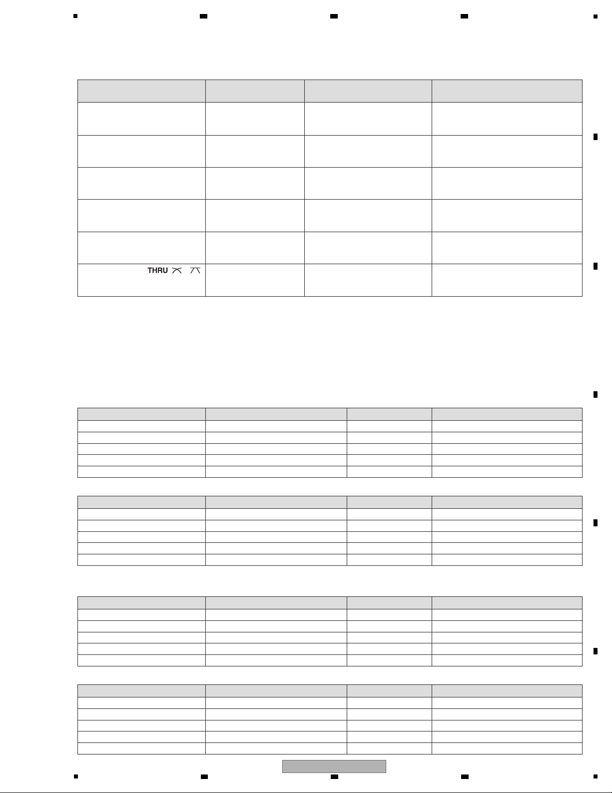
Items to be checked after servicing
1 Check the firmware version.
To keep the product quality after servicing, confirm recommended check points shown below.
The firmware version must be the latest one.
If it is not the latest one, be sure to update it.
2 Confirm whether the customer complain has been solved.
The customer complain must not be reappeared.
Audio and operations must be normal.
3
Check the analog audio output.
There must be no errors in audio output and operations of each
channel.
5
Check playback, using the fader function.
There must be no errors in audio output and operations of each
channel.
6 Check the MASTER output. Audio and operations must be normal.
7 Check the headphones output. There must be no errors, such as noise, in the audio output.
9 Check the appearance of the product.
Distortion
Noise
Volume too low
Volume too high
Volume fluctuating
Sound interrupted
No scratches or dirt on its appearance after receiving it for service.
Check playback, using the USB A. Audio and search etc. operations must be normal.
USB B The device must be properly recognized by the PC.
Wireless LAN The output signal can detect with a PC.
8
Check the connection of each interface.
4 Playback a CD disc. (track search) Audio, Search and operations must be normal.
See the table below for the items to be checked regarding audio.
No. Procedures
Item to be checked regarding audio
Check points
Lubricants and Glues List
Jigs List
Jig Name Part No. Purpose of use / Remarks
Position to be cleaned Name Part No.
Remarks
USB cable GGP1193 for PC connection
Name Part No. Remarks
Adhesive GYL1001
Pickup lens
Cleaning liquied
GEM1004
Cleaning paper GED-008
Refer to "7. DISASSEMBLY".
Refer to "7. DISASSEMBLY".
Adhesive GYL1005 Refer to "7. DISASSEMBLY".
Grease GEM1072 Refer to "7. DISASSEMBLY".
Silicon bond GYA1011 Refer to "7. DISASSEMBLY".
rekordbox
Supplied software
It must be confirmed that music files playbacked in the PC can be
transferred to the XDJ-R1 via wireless LAN, using rekordbox installed
on the PC. You can download rekordbox from the Pioneer Web site.
Cleaning
Before shipping out the product, be sure to clean the following positions by using the prescribed cleaning tools.
2 3 4
3. BASIC ITEMS FOR SERVICE
3.1 CHECK POINTS AFTER SERVICING
A
B
C
D
3.2 JIGS LIST
E
F
6
1
XDJ-R1
2 3 4
Page 7
5
Mark No. Description Part No. Mark No. Description Part No.
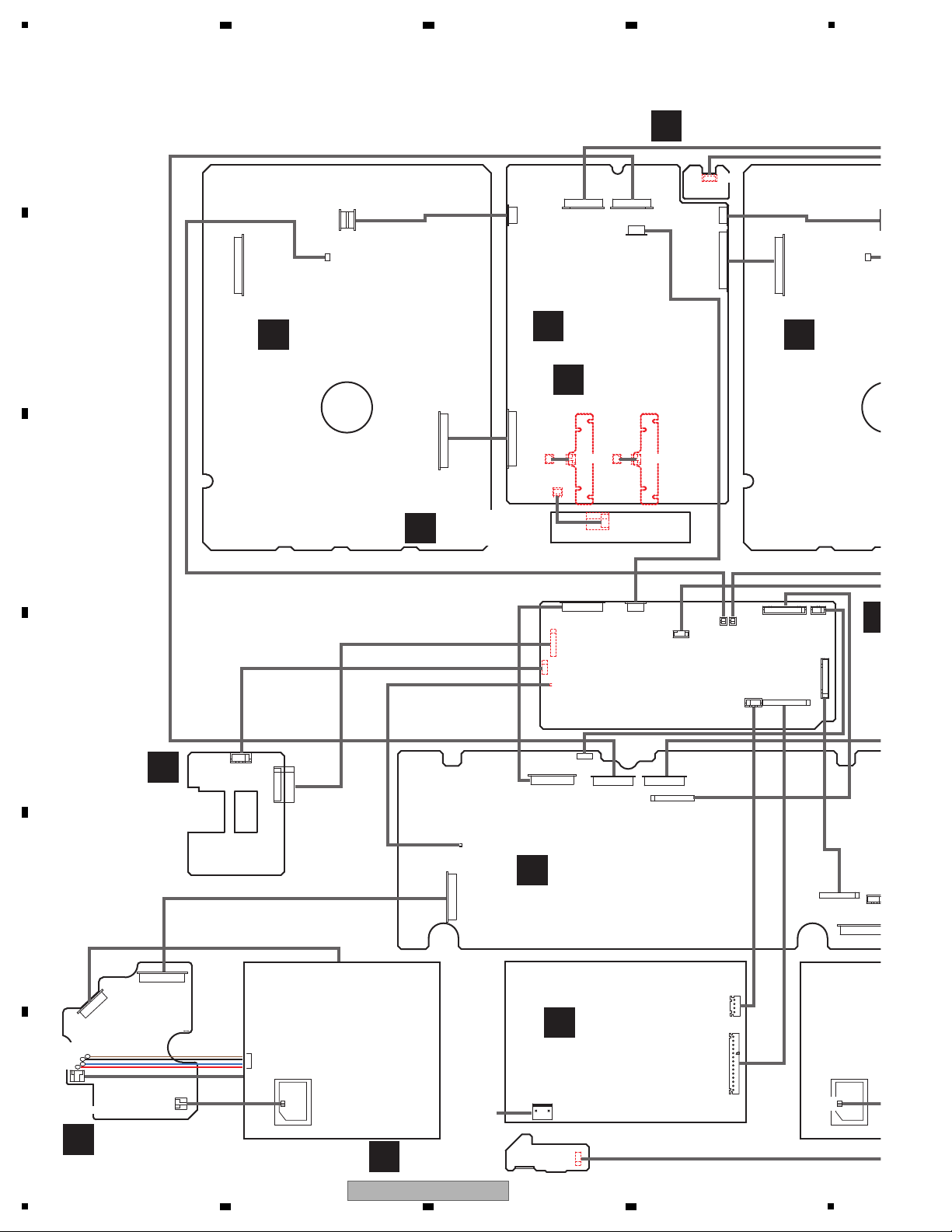
LIST OF ASSEMBLIES
NOTES: - Parts marked by “NSP” are generally unavailable because they are not in our Master Spare Parts List.
-
The > mark found on some component parts indicates the importance of the safety factor of the part.
Therefore, when replacing, be sure to use parts of identical designation.
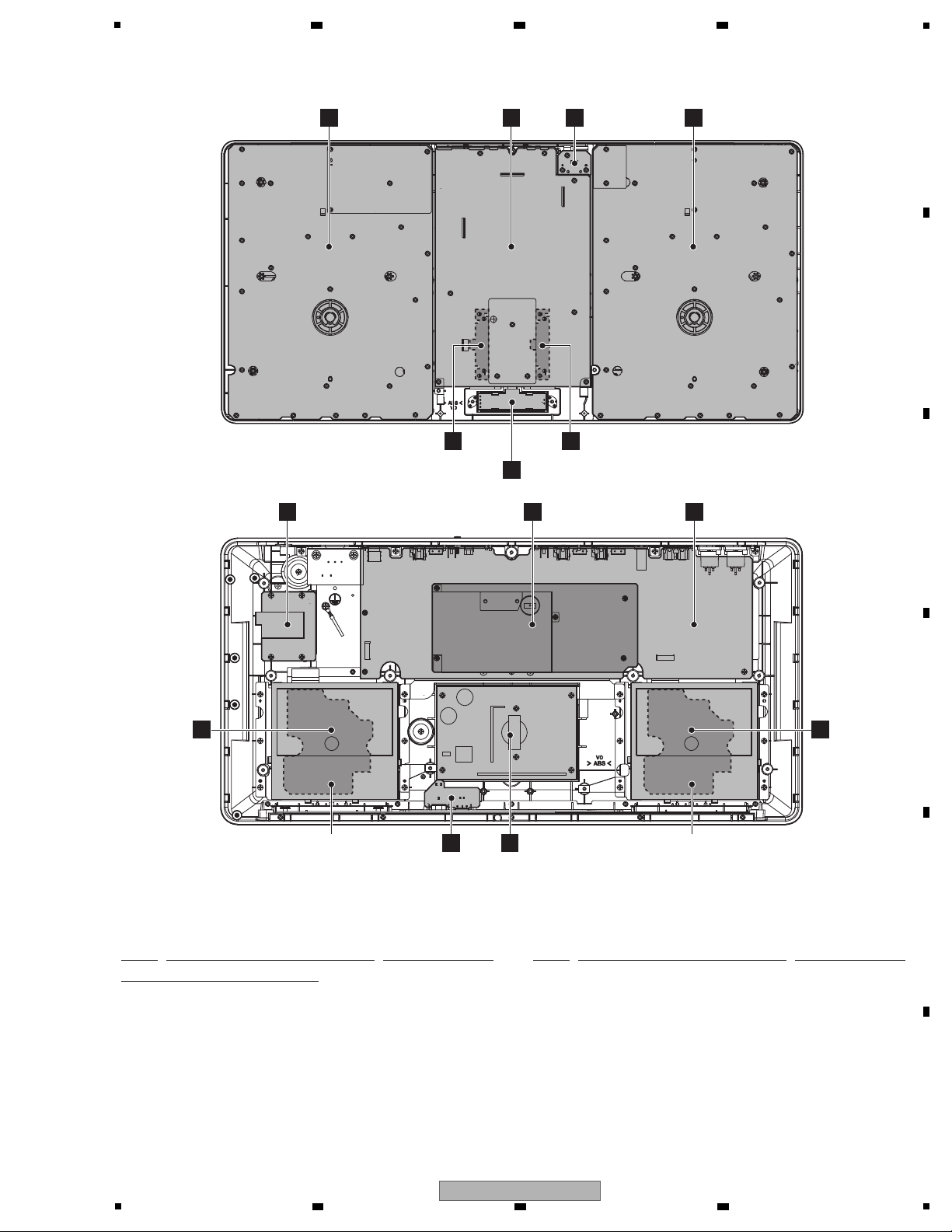
I/O ASSY 704-COMBO-A378
MIXER ASSY 704-COMBO-A376
CH ASSY 704-COMBO-A482
CROSS FADER ASSY 704-COMBO-A499
USB ASSY 704-COMBO-A381
PHONES ASSY 704-COMBO-A379
DSP & POWER ASSY 704-COMBO-A531
Wi-Fi PCB ASSY 704-COMBO-A380
CD1 ASSY 704-COMBO-A375
CD2 ASSY 704-COMBO-A476
SERVO ASSY 704-COMBO-A377
SWITCHING POWER 411-COMBO-887
SLOT-IN FEEDER MECHA ASSY
704-MCU300-9997-HA
D
CROSS FADER ASSY
F
PHONES
ASSY
K
SWITCHING
POWER
SLOT-IN FEEDER
MECHA ASSY
SLOT-IN FEEDER
MECHA ASSY
A
I/O ASSY
J
SERVO
ASSY
J
SERVO
ASSY
G
DSP & POWER
ASSY
H
Wi-Fi
PCB ASSY
C
CH ASSY (CH1)
C
CH ASSY (CH2)
E
USB ASSY
B
MIXER ASSY
I
CD2 ASSY
I
CD1 ASSY
3.3 PCB LOCATIONS
6 7 8
A
B
C
5
XDJ-R1
6 7 8
D
E
F
7
Page 8
1
A
I/O ASSY
(704-COMBO-A378)
B
MIXER ASSY
(704-COMBO-A376)
C
CH ASSY
(704-COMBO-A482)
(CH1)(CH2)
E
USB ASSY
(704-COMBO-A381)
F
PHONES ASSY
(704-COMBO-A379)
DS
(70
G
H
Wi-Fi PCB ASSY
(704-COMBO-A380)
I
CD1 ASSY
(704-COM
I
CD2 ASSY
(704-COMBO-A476)
J
SERVO ASSY
(704-COMBO-A377)
SLOT-IN FEEDER
MECHA ASSY
(DECK1)
SLOTMECH
(DECK
K
SWITCHING POWER
(411-COMBO-887)
CN2
W402B
CN102A
CN101
CN101
CN106
MOTOR
GND
S1
S0
PICKUP
CN105
W402A
W811
W806
CN808
CN810
CN806
CN809
W4
CN40
W5
W6
CN200CN210CN810
CN4
CN5
CN6
CN810
CN209
CN804
CN812A
CN812B
CN200 CN210
CN201
CN204
W203
W208B W208A
CN01
CN206B
CN201
CN204
W206
W812
CN201
W
W81
CN206A
CN209
CN1
W203
AC IN
CN2
W3
CN3
CN208 CN208
D
CROSS FADER ASSY
(704-COMBO-A499)
SP+ (RED)
SP- (BLUE)
LMB (BLACK)
LMA (BROWN)
1. -Ef
2. +Ef
1. VB
2. D-
3. D+
4. DGND
5. DGND
1. SAD3.3V
2. CR0F
3. SADGND
1. +Ef 3.4V /V7
2. -EF
3. GND
4. +32V/V6
1. L
2. G
3. G
4. R
1. CLKIN
2. GND
1. 7V
2. M
3. M
4. P
5. ST5V
6. A-15V
7. A+15V
8. A
9. STBY
10. MUTE
11. /MST
1. A5V
2. A3.3V
3. ADDA
4. ADDA
5. D
6. D
7. V-CHK
8. D5V
9. PD
10. 5V
11. 32V
12. D3.3V
1. Vcc
2. VC
3. VEE
4. E
5. B
6. C
7. D
8. A
9. F
10. PD
11. AGND
12. LD
13. VR
14. FC-
15. TC-
16. TC+
17. FC+
1. D3.3V
2. D3.3V
3. GND
4. GND
1. D_MOSI
2. D_MI
3. WSCK
4. GND
5. PF0
6. PF1
7. /WRST
8. GND
1. + 7V/V1
2. + 7V/V1
3. GND
4. GND
5. ST5V/V2
6. GND
7. +15V/V3
8. GND
9. -15V/V4
10. GND
11. GND
12. +6V/V5
13. +6V/V5
14. STBY:5V->Power ON
LN
1. SAD3.3V
2. CR0F
3. SADGND
1. SAD3.3V
2. AD16
3. SADGND
1. SAD3.3V
2. AD15
3. SADGND
1. -Ef
2. +Ef
1. -Ef
2. +Ef
1. -Ef
2. +Ef
GND
S1
S0
89
7
6
4
3
1
a
W205
1. SL-
2. SL+
3. Disc Detecting Switch
4. S3.3V
1. Q1
2. Q2
3. DGND
2 3 4
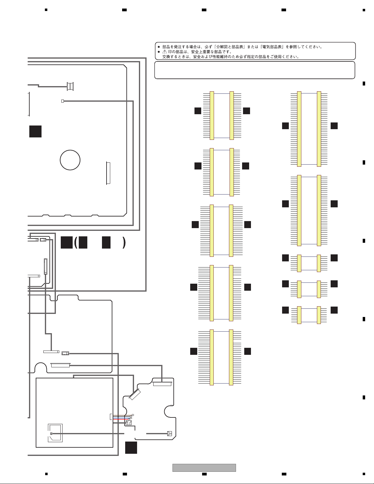
4. BLOCK DIAGRAM
4.1 OVERALL WIRING DIAGRAM
A
B
C
D
E
F
8
1
XDJ-R1
2 3 4
Page 9
1
2
3
4
5
6
7
8
9
10
11
12
13
14
15
16
17
18
19
20
21
22
23
24
25
26
CN810
D
D
D
D
D
D
D
UTX"
DO1
DO2
CD2 SCOR2
1
2
3
4
5
6
7
8
9
10
11
12
13
14
15
16
17
18
19
20
21
22
23
24
25
26
CN810
CN808
DGND
DGND
CDRST
MCK
R/W
BUSY
SUBDA
SUBCK
SCOR1
1
2
3
4
5
6
7
8
9
10
11
12
13
14
15
16
17
18
19
20
21
22
23
24
25
26
27
28
1
2
3
4
5
6
7
8
9
10
11
12
13
14
15
16
17
18
19
20
21
22
23
24
25
26
27
28
CN102A
DD1
3.3V
3.3V
S3.3V
S3.3V
AGND
7V
7V
1
2
3
4
5
6
7
8
9
10
11
12
13
14
15
16
17
18
19
20
21
22
23
24
CN210
406-COMBO-1255
SAD3.3V
SADGND
SADGND
SADGND
SADGND
SADGND
SADGND
SADGND
SADGND
SADGND
SADGND
SADGND
SADGND
AD3
AD7
AD9
AD10
AD11
AD12
AD15
AD16
AD17
AD18
CROF
1
2
3
4
5
6
7
8
9
10
11
12
13
14
15
16
17
18
19
20
21
22
23
24
CN210
SAD3.3V
SADGND
SADGND
SADGND
SADGND
SADGND
SADGND
SADGND
SADGND
SADGND
SADGND
SADGND
SADGND
AD3
AD7
AD9
AD10
AD11
AD12
AD15
AD16
AD17
AD18
CROF
1
2
3
4
5
6
7
8
9
10
11
12
13
14
15
16
17
18
19
20
21
22
23
24
CN200
SCL
SDA
/URST
D5V
5V
5V
32V
ST5V
STBY
SWB
SWA
1
2
3
4
5
6
7
8
9
10
11
12
13
14
15
16
17
18
19
20
21
22
23
24
CN200
D
D
D
D
1
2
3
4
5
6
7
8
9
10
11
12
13
14
15
16
17
18
19
20
21
22
23
24
25
26
27
28
29
30
31
32
33
34
35
36
37
38
CN201
DSO1/2
DSO2/8
DSO5/6
AD3/7
AD1/5
AD2/6
AD4/8
1
2
3
4
5
6
7
8
9
10
11
12
13
14
15
16
17
18
19
20
21
22
23
24
25
26
27
28
29
30
31
32
33
34
35
36
37
38
CN201
STCP
AGND
AGND
D5V
AD5V
VH
SCK
5V
D
D
D
/OE1
SADGND
SADGND
SAD3.3V
STCP
DSO2
DSO6
5V
SCK
D
D
D
D
D5V
VH
AD
AD
AD5V
/OE1
1
2
3
4
5
6
7
8
9
10
11
12
13
14
15
16
17
18
19
20
21
22
23
24
25
26
27
28
29
30
31
32
33
34
35
36
CN204
SADGND
SAD3.3V
AD3/7
AD1/5
AD2/6
AD4/8
1
2
3
4
5
6
7
8
9
10
11
12
13
14
15
16
17
18
19
20
21
22
23
24
25
26
27
28
29
30
31
32
33
34
35
36
CN204
1
2
3
4
5
6
7
8
CN206A
DATA1
1
2
3
4
5
6
7
8
W206
GND
GND
URX
UTX
1
2
3
4
5
6
7
8
CN209
GND
GND
1
2
3
4
5
6
7
8
CN209
DSP & POWER ASSY
(704-COMBO-A531)
G
G G
1/2,
2/2
I
CD1 ASSY
(704-COMBO-A375)
SLOT-IN FEEDER
MECHA ASSY
(DECK2)
J
SERVO ASSY
(704-COMBO-A377)
PICKUP
CN101
CN101
CN106
CN105
CN102A
CN809
W4
CN401
CN4
CN6
CN201
CN204
W206
W812
W3
1. L
2. GND
3. GND
4. R
1. 7V
2. M
3. M
4. P
5. ST5V
6. A-15V
7. A+15V
8. A
9. STBY
10. MUTE
11. /MST
1. Vcc
2. VC
3. VEE
4. E
5. B
6. C
7. D
8. A
9. F
10. PD
11. AGND
12. LD
13. VR
14. FC-
15. TC-
16. TC+
17. FC+
1. -Ef
2. +Ef
SP+ (RED)
SP- (BLUE)
LMB (BLACK)
LMA (BROWN)
MOTOR
GND
S1
S0
-
When ordering service parts, be sure to refer to "EXPLODED VIEWS and PARTS LIST" or "PCB PARTS LIST".
-
The > mark found on some component parts indicates the impor tance of the safety factor of the part.
Therefore, when replacing, be sure to use parts of identical designation.
B
MIXER ASSY
B
MIXER ASSY
A
I/O ASSY
B
MIXER ASSY
I
CD1 ASSY
A
I/O ASSY
G
DSP & POWER
ASSY
A
I/O ASSY
1
406-COMBO-1249
6
B
MIXER ASSY
I
CD2 ASSY
I
CD1 ASSY
B
MIXER ASSY
406-COMBO-1250
7
406-COMBO-1251
8
8
406-COMBO-1247
2
404-COMBO-1244
3
J
SERVO
ASSY
A
I/O ASSY
406-COMBO-1245
406-MEP4-1201
4
5
2
/INT1
LN1-SW
LN2-SW
AUX-SW
V-CHK
LN1-G
LN2-G
PD
PD
SCL
SDA
/URST
D5V
5V
5V
32V
ST5V
STBY
SWB
SWA
D
D
D
D
/INT1
LN1-SW
LN2-SW
AUX-SW
V-CHK
LN1-G
LN2-G
PD
PD
LRCK1
LRCK2
BCK1
BCK2
BCK3
LRCK3
D09
D010
SPI SCK"
SPI MOSI/MI
SPI CS"
CD1 SCOR1
/RST-532
SPI HREQ
SPI RTS
D
D
D
D
D
D
D
UTX"
DO1
DO2
CD2 SCOR2
LRCK1
LRCK2
BCK1
BCK2
BCK3
LRCK3
D09
D010
SPI SCK"
SPI MOSI/MI
SPI CS"
CD1 SCOR1
/RST-532
SPI HREQ
SPI RTS
DISC SW1
DISC SW2
OPSW
CLSW
LMDLMD+
DIO
WFCK
BCK1
LRCK1
PGND
DGND
DGND
CD1 CDRST
CD1 MCK
CD1 R/W
CD1 BUSY
CD1 SUBDA
CD1 SUBCK
CD1 SCOR1
DO1
3.3V
3.3V
A3.3V
A3.3V
AGND
7V
7V
CD1 DISC SW1
CD1 DISC SW2
CD1 OPSW
CD1 CLSW
CD1 LMDCD1 LMD+
CD1 DIO
CD1 WFCK
BCK1
LRCK1
PGND
CN809
DGND
DGND
CDRST
MCK
R/W
BUSY
SUBDA
SUBCK
SCOR1
1
2
3
4
5
6
7
8
9
10
11
12
13
14
15
16
17
18
19
20
21
22
23
24
25
26
27
28
1
2
3
4
5
6
7
8
9
10
11
12
13
14
15
16
17
18
19
20
21
22
23
24
25
26
27
28
CN102A
DD1
3.3V
3.3V
S3.3V
S3.3V
AGND
7V
7V
J
SERVO
ASSY
A
I/O ASSY
406-COMBO-1245
406-MEP4-1201
5
DISC SW1
DISC SW2
OPSW
CLSW
LMDLMD+
DIO
WFCK
BCK1
LRCK1
PGND
DGND
DGND
CD2 CDRST
CD2 MCK
CD2 R/W
CD2 BUSY
CD2 SUBDA
CD2 SUBCK
CD2 SCOR1
DO2
3.3V
3.3V
A3.3V
A3.3V
AGND
7V
7V
CD2 DISC SW1
CD2 DISC SW2
CD2 OPSW
CD2 CLSW
CD2 LMDCD2 LMD+
CD2 DIO
CD2 WFCK
BCK2
LRCK2
PGND
PGND
PGND
PGND
LAT1
BK1
PA1
PB1
KR1
/PL
STB-LED
STB-SW
KS1
KS2
KS3
KS4
KS5
KS1
KS2
KS3
KS4
KS5
DSO1/2
DSO2/8
DSO5/6
AD3/7
AD1/5
AD2/6
AD4/8
STCP
AGND
AGND
D5V
AD5V
VH
SCK
5V
GND
GND
GND
/OE1
SADGND
SADGND
SAD3.3V
PGND
PGND
PGND
LAT1/2
BK1/2
PA1/2
PB1/2
KR1/2
/PL
STB-LED
STB-SW
KS1
KS2
KS3
KS4
KS5
PD
PD
PD
LAT2
BK2
PA2
PB2
KR2
/PL
MISO
STCP
DSO1/2
DSO6/3
5V
SCK
D
D
D
D
D5V
VH
AD
AD
AD5V
/OE1
SADGND
SAD3.3V
AD3/7
AD1/5
AD2/6
AD4/8
KS1
KS2
KS3
KS4
KS5
PD
PD
PD
LAT1/2
BK1/2
PA1/2
PB1/2
KR1/2
/PL
DSO5/6
CLK1
LS1
LS2
LS3
LS4
DATA
GND
GND
CLK
LS1
LS2
LS3
LS4
1
2
3
4
5
6
7
8
CN206B
DATA2
1
2
3
4
5
6
7
8
W206
GND
GND
I
CD2 ASSY
B
MIXER ASSY
B
MIXER ASSY
G
DSP & POWER
ASSY
406-COMBO-1251
9
406-COMBO-1248
a
CLK2
LS1
LS2
LS3
LS4
DATA
GND
GND
CLK
LS1
LS2
LS3
LS4
PA1
PB1
PA2
PB2
URX
UTX
GND
GND
PA1
PB1
PA2
PB2
1. SL-
2. SL+
3. Disc Detecting Switch
4. S3.3V
1. Q1
2. Q2
3. DGND
5
5
6 7 8
XDJ-R1
6 7 8
A
B
C
D
E
F
9
Page 10
1
MCL K
TP S54
BD4745
6V
+15V
-15V
BUC
Compare
LI NE1/P H1
-9.05dB
-9.05dB
-9.05dB
ADC
PCM1803
NJM4580
0dB
RIAA
+36dBPH
NJM4580
2
C 1
1
LN/PH
+20dB
ADC
LN
LI NE2/P H2
ADC
NJM4580
0dB
RIAA
+36dBPH
NJM4580
2
C 1
1
LN/PH
LN
AUX
ADC
NJM4580
2C11
Boost
L
3
R
2
G
1
S
4
MI C.
+11dB
NJM2068
BU9543K V
CD DSP
BA5826FP
4CH Driver
BA6218
Motor Driver
STM8S207MBT3
CD MCU
SP/SL
Motor
Motor
Load
Spindle
Slide
Focus Track
16.9344M
Opitical
12
Disc
Sensor
SP/SL
Motor
Motor
Load
Spindle
Slide
Focus Track
16.9344M
Opitical
12
Disc
Sensor
DECK DSP
parallel
parallel
BCK 1
LRCK 1
BCK 2
LRCK 2
DO1
DO2
DO3
DO4
RX0 I2S
RX1 I2S
Flash ROM
29W800D
SDRAM* 2
IS42S83200G
ISP1761
USB IF
CD1 /RST
SPI
SPI
AXM22001
WiF i Module
ANT
USB Host
DSP567
TX0 I2S
TX1 I2S
DO5
DO6
TU
ICS501
2*PL L
74HC4050
Buffer
SCK 3
BCK
LRCK
BCK 3
LRCK 3
BCK 3
LRCK 3
BCK 3
LRCK 3
BCK 3
LRCK 3
TX used BCK3&L RCK 3
DI 1DO7 D
SDRAM*
EM638165T
LATCH* 2
74LV573
6V/4A,+15V&- 15V/0.4A,7V/2A
STB5V/0.2A,32V/0.35A
+Ef&- Ef(3.4V/0.8A)
+Ef -Ef
VF D Filament
7V
CD Driv
er
STB5V
UI MCU
OPA
BA0
LDO
TP S54
BUCK
BA0
LDO
A5V
AC Plug
STBY
LD11
2.5V(Ek)
74HC14
(HW)
18.432M
/RST -532
/RST- 724
SPI(SW)
CD2 /RST
EN25Q64
Flash MEMO.
SCK 3
BCK 3
LRCK 3
BCK 3
LRCK 3
Buffer
SCK 4
SCK 4
Buffer
SCK 4 SCK 4A
Buffer
SCK 3A SCK 3
24.576M
12M
SLOT-IN FEEDER
MECHA ASSY
(DECK1)
SLOT-IN FEEDER
MECHA ASSY
(DECK2)
SERVO ASSY
SERVO ASSY
SWITCHING POWER
DSP & POWER
ASSY
DSP & POWER
ASSY
I/O ASSY
SWITCHING POWER
Power
Delay
ADSP-BF532
Hysteresis
MIXER
SN74LVC1G17
USB
SN74LVC1G17
SN74LVC1G17
IC416
IC418
IC419
IC420
IC421
IC814
IC815
IC401
IC
IC40
IC402
IC813
IC802
IC805
IC815
IC414,IC415 IC412,IC4
IC811
IC812
IC7
IC4
IC1
IC2
IC3
IC5
IC803
IC813,IC814
IC816
X801
X401
X402
X
IC417
IC403
PCM1803
IC405
PCM1803
IC404
PCM1803
IC406
IC102
BA5826FP
4CH Driver
IC102
IC101
BU9543K V
CD DSP
IC101
IC103
BA6218
Motor Driver
IC103
X102
X102
SI,SO,/CS,SCK
F
QS3245
Buffer
74HCT08
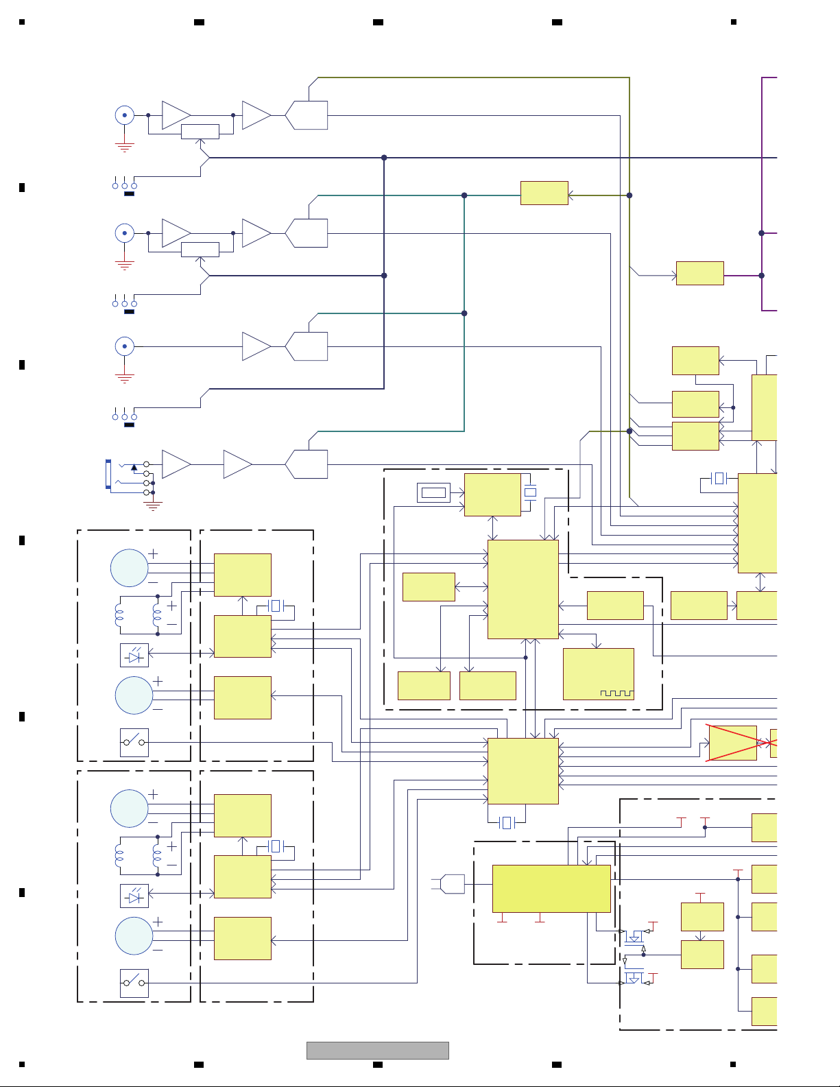
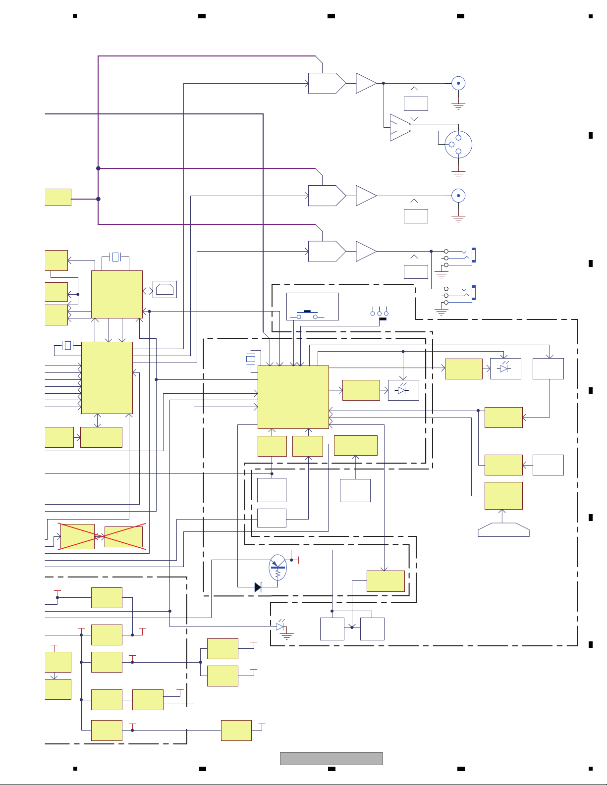
2 3 4
4.2 OVERALL BLOCK DIAGRAM
A
B
C
D
E
F
10
1
XDJ-R1
2 3 4
Page 11
5
USB PortB
Tact SW
EXT. AD
HC4052* 2
X.Curve
PIC16F 16*2
PWM
TOUCH P L AT* 2
Wheel
Encoder
SER.- ->PAL .
74595
MCL K
6M
U5V
MASTER OUT(RCA)
Rotary*7
Fast
TP S54232
BD4745
D3.3V
6V
BUCK
A5V
Rotary*15
send
return
NJM4580
D5V
DSP56724
TUSB3200
CS501
BCK
LRCK
DI 1DO7 DO8
MUTE
2
3
1
BOOTH OUT(RCA)
NJM4580
MUTE
DAC
NJM4556
MUTE
L
3
R
2
G
1
JK9
L
3
R
2
G
1
JK9
DI 2
DI 3
DI
4
SDRAM* 2
EM638165TS
STM8S207MBT3
UI MCU
I2C,I NT
TX,RX
74HC165
74HC165
PAL .-->SER.
PAL .-->SER.
CP ,/PL,D1,D2
Encoder
*6
Rotary
*64
*31
*54
*2
Normal
DECK 1
VFD
DECK 2
VFD
Serial
-Ef
Filament
32V
VFD Driv er
BA05
LDO
TP S54232
BUCK
BA05
LDO
A5V
DAC
USB Host
Current CHK
LD1117
2.5V(Ek)
+16.8dB
+16.8dB
+4dB
+10.95dB
BD12K A
LDO
D1.2V
DSP Core
Stand By
TP S2553
Curr.L TD
min.1100mA
STM8S003F3
VFD MCU
TX1/RX1
18.432M
/URST
Comparator
LM339
X.F ader
2
C 1
1
FUCN. SW.* 2
Hy steresis
74HC14
Buffer
SCK 4A
ADC
AD3.3V_1
BU33TD3
ADC
AD3.3V_2
BU33TD3
24.576M
ER
CD ASSY
MIXER ASSY
I/O ASSY
Power
Delay
MCU,PLL,Logic,VFD
DSP,SDRAM,Wi-Fi,
USB IF,Servo Driver,
FlashRom
MIXER DSP
4LVC1G17
USB Controllor
MASTER OUT(XLR)
1/4" PHONES OUT
3.5mm PHONES OUT
HP Cue1/Cue2
Comment: STBY SW
2nd order LPF
2nd order LPF
2nd order LPF
LEDs
LEDs
IC400
IC408
IC7
IC4
IC1
IC2
IC3
IC5
IC407
IC817
IC816
IC100
IC207
IC101
IC104
IC103
IC209 IC208
IC200
IC202
SER.- ->PAL .
74595
IC102
IC425
IC424
IC423
IC422
PCM1754
IC411
DAC
PCM1754
IC410
DAC
PCM1754
IC409
X200
IC203,IC205
IC100
IC6
X400
EN25F 10
Flash MEMO.
QS3245
Buffer
74HCT08
6 7 8
A
B
C
D
E
5
XDJ-R1
6 7 8
F
11
Page 12
1
12
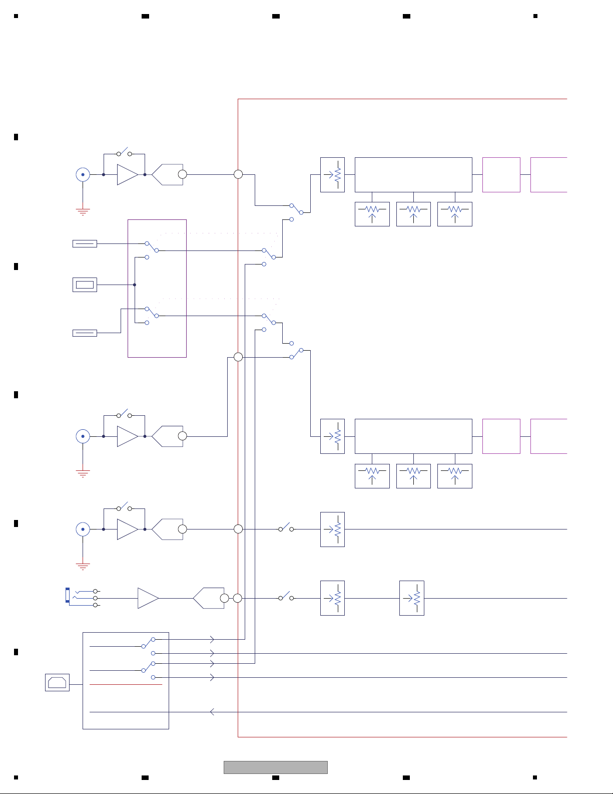
LN/P H SW
ADC
31
2
31
2
31231
2
12
LN/P H SW
ADC
31
2
31
2
31231
2
AUX
12
LI NE BOOST
L/R
ADC
L
3
R
2
G
1
ADC
12
12
31
2
31
2
31
2
USB PortB
1
2
C1
1
2
C1
USB Audio IN
USB Audio OUT
CH1 CD Deck
CH2 CD Deck
1
2
C1
1
2
C1
1
2
C1
1
2
C1
USB IN1
USB IN2
DECK DSP
MIXER DSP
SOURCE Select
SOURCE Select
CH1
CH2
USB Audio Mix
USB Audio HP
USB MASTER OUT
USB Audio IN1
USB Audio IN2
EQ
1
2
C1
1
2
C1
PC,USB,CD Select
PC,USB,CD Select
CH-1
LINE/PHONO
L/R
CH-2
LINE/PHONO
L/R
USB PortA
MIC mono
6.4mm
AUX Input level
AUX ON/OFF
MIC ON/OFF
MIC Input level
3 Band Isolator
3 Band Isolator
ROLL
EFFECT
COLOR
EFFECT
ROLL
EFFECT
COLOR
EFFECT
IC403
IC805
IC405
IC404
IC406
IC408
12
12
12
12 98
86
87
88
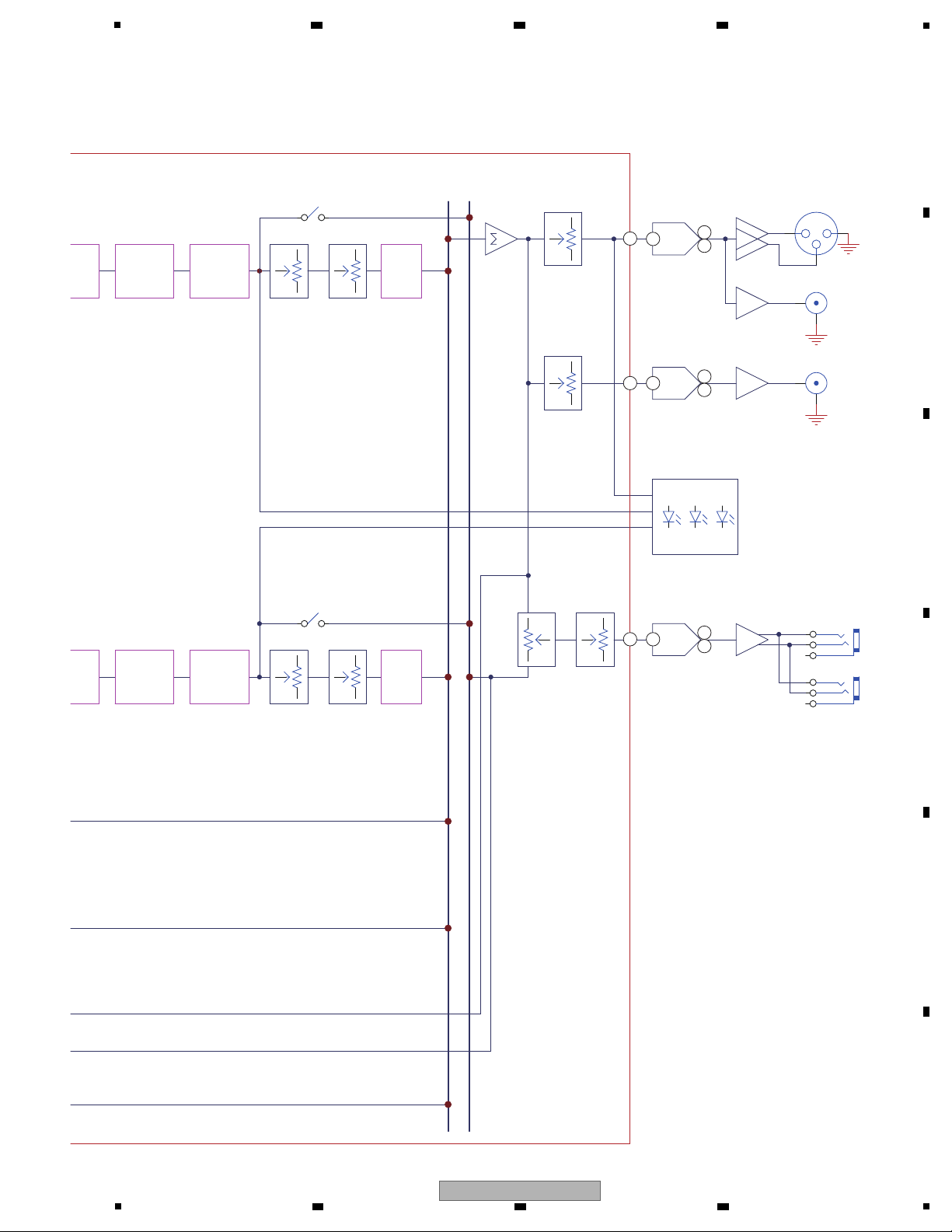
4.3 SYSTEM BLOCK DIAGRAM
A
B
2 3 4
C
D
E
F
12
1
XDJ-R1
2 3 4
Page 13
31
2
31
2
31
2
DAC
MASTER2(RCA)
DAC
31
2
BOOTH(RCA)
2
3
1
31
2
DAC
31
2L
3
R
2
G
1
L
3
R
2
G
1
Phones JACK
6.4mm
3.5mm
M ASTER
C UE
12
CH1 CUE
31
2
31
2
12
CH2 CUE
MAS CH2CH1
LEVEL Meter
ECT
COLOR
EFFECT
TRANS
FLANGER
EFFECT
ECT
COLOR
EFFECT
TRANS
FLANGER
EFFECT
ECHO
EFFECT
ECHO
EFFECT
MASTER TRIM
BOOTH TRIM
MASTER/CUE
MIX
HP LEVEL
MASTER(XLR)
BALANCE
IC408
IC409
IC410
2
7
8
2
7
8
125
124
IC411
2
7
8
122
5
6 7 8
A
B
C
D
E
F
XDJ-R1
5
6 7 8
13
Page 14
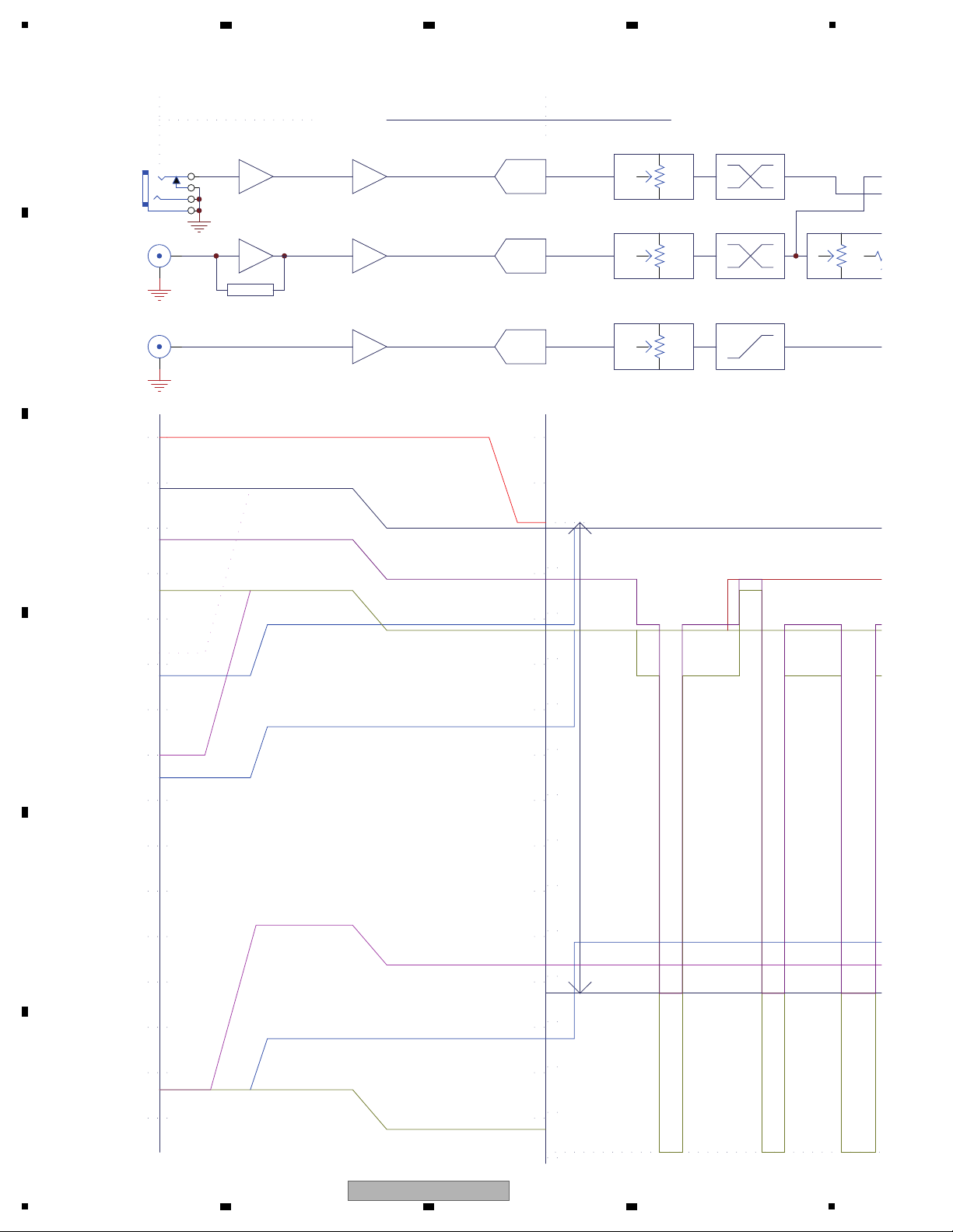
1
Line/P hono
-9.05
A/D
dBV
Max Input Lev el
0
10
20
-10
-20
-30
-40
-50
-60
-70
-80
-90
-100
-110
-120
-130
PCM1803
dBV
0
10
20
-10
-20
-30
-40
-50
-60
-70
-80
-90
-100
-110
-120
-130
dBF S
31
2
EQ
31
23
2
CH.F ader * C
0(+0.5dBV)
-10
-20
-30
-40
-50
-60
-70
-80
-90
-100
-110
-120
-130
DR:103dB
-140
-9.05
NJM4580
11dBu(8.79dBV)
-0.26dBV
200mVrm s
-14dBV
AUX Boost
+9~ -∞ dB
-9.05
-144dBF S@24bit
Noise Level
@-123dBV
Clip=19.59dBV
MI C Level
-54dBV
+9.9
Phono Level
-50dBV
+36
RIAA
LN:0
PH:+36
0~-9~ -∞ dB 0~ -∞ dB
AUX
A/D
PCM1803-9.28
NJM4580
31
2
0~-9~ -∞ dB
NJM4580
+9.9
ADC
PCM1803
L
3
R
2
G
1
S
4
NJM2068
+0
NJM2068
TONE
0~ -12 dB
31
2
0~-9~ - ∞ dB
Boost
0~+12dB
-23.05dBV
Center
Max.
-23.55dBF S
Phono Noise
-96.05dBV
-32.55dBF S
MI C Noise -113.1dBV
Max.P hono Level -25dBu
Max. MIC Level
-29dBu
DR:103dB
DR:103dB
DR:103dB
-20.76dBF S
Reference level 0dBu
+12
+21
DSP Gain
ANALOG
limit +0.5dBV
limit +0.5dBV
MIC.
GAIN
GAIN
TRIM
DIGITAL
4.4 LEVEL BLOCK DIAGRAM
A
2 3 4
B
C
D
E
F
14
1
XDJ-R1
2 3 4
Page 15
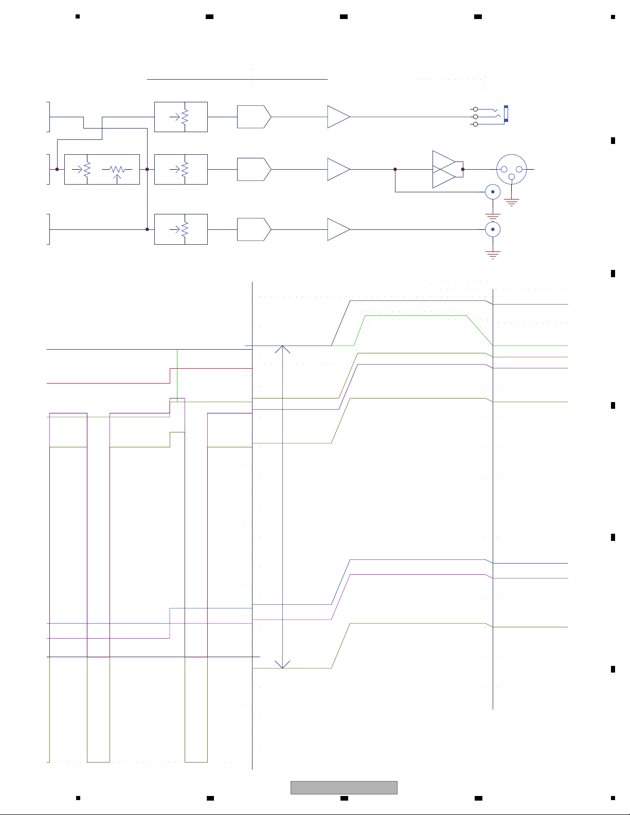
5
31
231
2
CH.F ader * CR.Fader
dBV
0
10
20
-10
-20
-30
-40
-50
-60
-70
-80
-90
-100
-110
-120
-130
D/A
DR:106dB
PCM1754
0dBF S=3dBV
31
2
Master Level NJM4580
Master Out
DR:105.24dB
Max.
+4
2
3
1
NJM4556
12.55dBV
+17.79
25dBu
dBV
0
10
20
-10
-20
-30
-40
-50
-60
-70
-80
-90
-100
-110
AUX Boost
-29.55dBV
+16.8
+10.95
11.07dBV
3dBV
BAL ANCE
AUX L ev el 12dBV
Unbalance Out 0dBV
dBF S@24bit
DSP-->DA@- 87.41dBV
Clip=19.59dBV Unbalance Clip
Balance Clip=25.59dBV
D/A
DR:123dB
PCM1754
0dBF S=3dBV
31
2
+10.95
Phones Max. 70mW
Unbalance Max. 20dBu
Phones Clip +14dBV
L
3
R
2
G
1
PHONES
+20~ -∞ dB
0~ -∞ dB +5~ -∞ dB
D/A
DR:106dB
PCM1754
0dBF S=3dBV
31
2
Booth Level NJM4580
+5~ -∞ dB
RCA
Booth Out
RCA
80%position
100%position
-15.55dBV
+16.8
Unbalance Out -14dBV
2.24dBV(Max.)
+5
Phono@- 72.77dBV
0
-10
-20
-30
-40
-50
-60
-70
-80
-90
-100
-110
-120
-130
dBF S
+16.8
-32.55dBF S
CUE
90%position
MIC@- 68.78dBV
80%position-20.76dBF S
Unbalance Out 0dBu(Ref.)
CUE Level
DIGITAL
ANALOG
XLR
6 7 8
A
B
C
D
E
F
5
6 7 8
XDJ-R1
15
Page 16

1
[1] Power failure
Symptom: SWITCHING POWER is fault.
Diagnostic procedure:
1. Check if SWITCHING POWER CN1: AC 100 V to AC 240 V is normal.
2. Check SWITCHING POWER CN3:
V1 → +7V, V2 → ST5V, V3 → +15V, V4 → -15V, V5 → 6V.
3. Check waveform for SWITCHING POWER, confirm it is correct.
SWITCHING POWER C28 positive to ground is +7V figure
(Waveform ).
SWITCHING POWER C47 positive to ground is ST5V figure
(Waveform ).
SWITCHING POWER C31 positive to ground is +15V figure
(Waveform ).
SWITCHING POWER C24 negative to ground is -15V figure
(Waveform ).
SWITCHING POWER C21 positive to ground is +6V figure
(Waveform ).
4. If Waveform is abnormal, you could change it.
[2] VFD dose not light
Symptom:
VFD module is fault, it is no light-emitting.
Diagnostic procedure:
1. Check waveform for VFD module, you confirm it is correct.
Check CD Assy C112 positive to ground is +Ef figure
(Waveform ).
Check CD Assy C112 negative to ground is -Ef figure
(Waveform ).
Check CD Assy C103 positive to ground is VH figure
(Waveform ).
2. If Waveform is abnormal, you could change it.
[3] LED dose not light
Symptom: LED part is fault, it is no light-emitting.
Diagnostic procedure:
1. Check waveform for LED, you confirm it is correct.
2. It is tested at CD Assy Q102 to Q105 pin C (CH1).
It is tested at CD Assy Q106 to Q112 pin C (CH2).
Waveform for LED ON is figure
(Waveform ).
Waveform for LED OFF is figure
(Waveform ).
3. If Waveform is abnormal, you could change it.
[4-1] No key functions
Symptom:
No key function.
Diagnostic procedure:
1. Check waveform for KEY, you confirm it is correct.
Waveform for KEY OFF is figure
(Waveform )
(CH1 → KEY pin 1/CH2 → KEY pin 2).
Waveform for KEY ON is figure
(Waveform )
(CH1 → KEY pin 1/CH2 → KEY pin 2).
2. If Waveform is abnormal, you could change it.
[4-2] Rotary selector not controllable
Symptom: Rotary selector of encoder switch is fault.
Diagnostic procedure:
1. Check waveform for rotary encoder, you confirm it is correct.
Waveform for rotary encoder is figure
(Waveform )
(CH1 → encoder pin 1/CH2 → encoder pin 3).
2. If Waveform is abnormal, you could change it.
[4-3] Slider volume not controllable
Symptom:
Crossfader and channel-fader VR is fault.
Diagnostic procedure:
1. Check waveform for VR, you confirm it is correct.
C802 (CROSSFADER), C807 (CH1 FADER), C806 (CH2 FADER) that positive to ground is VR out.
Waveform for min VR out is figure
(Waveform ).
Waveform for max VR out is figure
(Waveform ).
2. If Waveform is abnormal, you could change it.
1-1
1-2
1-3
1-4
1-5
2-1
2-2
2-3
3-1
4-1
4-2
4-3
4-4
4-5
3-2
2 3 4
5. DIAGNOSIS
5.1 TROUBLESHOOTING
A
B
C
D
E
F
16
1
XDJ-R1
2 3 4
Page 17

5
[6] Jog rotation can not be detected
Symptom: Jog rotation is fault.
Diagnostic procedure:
1. Check waveform for jog rotation circuit, you confirm CD Assy is correct.
2. CD Assy Q100 C pin (CH1) and Q101 C pin (CH2) is figure
(Waveform ).
3. If Waveform is abnormal, you could change it.
[7] Jog touch can not be detected
Symptom: Jog touch is fault.
Diagnostic procedure:
1. Check waveform for jog touch circuit, you confirm it is correct.
2. Check Waveform that CD Assy C113 positive to ground, if Waveform is abnormal.
3. Waveform without touch condition is figure
(Waveform ).
4. Waveform for touch is figure
(Waveform ).
[8] Disc can not be inserted or Ejected
Symptom: CD DECK is fault.
Diagnostic procedure:
1. Check waveform for SERVO Assy IC103 pin 7 LMA (CH1), pin 9 LMB (CH2), you confirm SERVO Assy is correct.
IC103 pin 7LMA (CH1) and pin 9 LMB (CH2) Waveform for insert disc is figure
(Waveform ).
IC103 pin 7LMA (CH1) and pin 9 LMB (CH2) Waveform for eject disc is figure
(Waveform ).
2. Check SERVO Assy CN102A pins 9 to 12 for CLSW (CH2)/OPSW (CH3)/DISC SW1 (CH1)/DISC SW2 (CH4).
CN102A pin 12 CLSW (CH2), pin 11 PSW (CH3), pin 9 DISC SW1 (CH1), pin 10 DISC SW2 (CH4) waveform
for no disc is figure
(Waveform ).
CN102A pin 12 CLSW (CH2), pin 11 PSW (CH3), pin 9 DISC SW1 (CH1), pin 10 DISC SW2 (CH4) waveform
for eject disc is figure
(Waveform ).
CN102A pin 12 CLSW (CH2), pin 11 PSW (CH3), pin 9 DISC SW1 (CH1), pin 10 DISC SW2 (CH4) waveform
for insert disc is figure
(Waveform ).
3. If Waveform is abnormal, you could change it.
6-1
[5] DECK, PHONO/LINE selector switch can not work
Symptom: DECK, PHONO/LINE selector switch is fault.
Diagnostic procedure:
1. Check waveform for DECK, PHONO/LINE selector switch, you confirm switch out is correct.
MIXER Assy C207 (CH1 SW) and C220 (CH2 SW) that positive to ground is switch out.
Waveform for switch on is figure
(Waveform ).
Waveform for switch off is figure
(Waveform ).
2. If Waveform is abnormal, you could change it.
5-2
5-1
7-1
8-1
8-2
8-3
8-4
8-5
7-2
[9] Spindle motor does not rotate
Symptom: CD DECK is fault.
Diagnostic procedure:
1. Check waveform for SERVO Assy IC102 pin 1 (SP-), 2 (SP+), you confirm it is correct.
Waveform for spindle motor is figure
(Waveform ).
2. If Waveform is abnormal, you could change it.
[10] No sound input/output from USB
Symptom: The USB audio not activated.
Diagnostic procedure:
1. Check Waveform for I/O Assy IC400 pin 35 (LRCK)
(Waveform )
, pin 34 (BCK)
(Waveform )
,
pin 44 (MCLKO)
(Waveform )
, you confirm it is correct.
2. If Waveform is abnormal, you could change it.
9-1
10-1
10-2
10-3
6 7 8
A
B
C
D
E
5
6 7 8
XDJ-R1
F
17
Page 18
1
[11] No sound output from MASTER1/MASTER2 (UNBALANCE)
Symptom: The audio output is not activated.
Diagnostic procedure:
1. Check Waveform for I/O Assy IC409 pin 16 (SCK)
(Waveform )
, pin 1 (BCK)
(Waveform )
,
pin 3 (LRCK)
(Waveform )
, pin 2 (DATA)
(Waveform )
, you confirm it is correct.
2. If Waveform is abnormal, you could change it.
11-1
11-2
11-3
11-4
[12] No sound output from BOOTH
Symptom: The audio output is not activated.
Diagnostic procedure:
1. Check Waveform for I/O Assy IC410 pin 16 (SCK)
(Waveform )
, pin 1 (BCK)
(Waveform )
,
pin 3 (LRCK)
(Waveform )
, pin 2 (DATA)
(Waveform )
, you confirm it is correct.
2. If Waveform is abnormal, you could change it.
12-1
12-2
12-3
12-4
[13] No sound output from PHONES
Symptom: The audio output is not activated.
Diagnostic procedure:
1. Check Waveform for I/O Assy IC411 pin 16 (SCK)
(Waveform )
, pin 1 (BCK)
(Waveform )
,
pin 3 (LRCK)
(Waveform )
, pin 2 (DATA)
(Waveform )
, you confirm it is correct.
2. If Waveform is abnormal, you could change it.
13-1 13-2
13-3 13-4
[14] No sound input from MIC1/MIC2
Symptom: The audio input is not activated.
Diagnostic procedure:
1. Check Waveform for I/O Assy IC406 pin 15 (SCK)
(Waveform )
, pin 11 (BCK)
(Waveform )
,
pin 10 (LRCK)
(Waveform )
, pin 12 (DOUT)
(Waveform )
, you confirm it is correct.
2. If Waveform is abnormal, you could change it.
14-1 14-2
14-3 14-4
A
2 3 4
B
C
D
E
F
18
1
2 3 4
XDJ-R1
Page 19
5
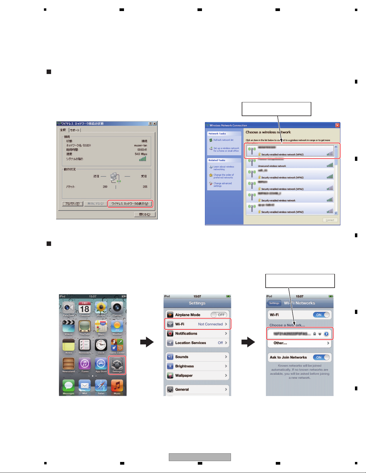
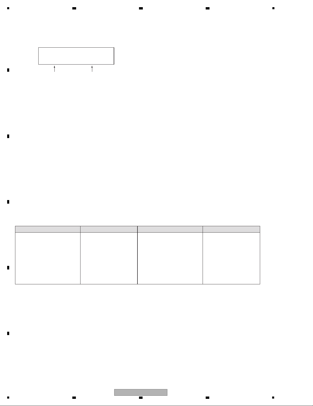
To confirm wireless LAN communication, confirm the SSID with this unit then confirm the signal with a PC equipped with
a wireless LAN device or with a smartphone/tablet PC.
1 Click on the wireless network icon on the system tray.
2 After the Wireless Network Connection Status dialog box is displayed, select the View Wireless Networks button.
3 When the "Choose a wireless network" dialog box is displayed, check that the SSID selected of this unit is displayed.
How to Confirm with a PC (Example: Windows XP)
1 On the top screen of an iPod touch, select Settings.
2 Select Wi-Fi (Not Connected)
3 Check that the SSID selected of this unit is displayed in the "Choose a Network" box.
How to Confirm with a Smartphone/Tablet PC (Example: iPod touch)
Check that the SSID selected
of this unit is displayed.
Check that the SSID selected
of this unit is displayed.
6 7 8
5.2 CONFIMATION OF WIRELESS LAN COMMUNICATION
A
B
C
D
E
F
XDJ-R1
5
6 7 8
19
Page 20

1
Error indication
Error contents
E-6002 DSP DEVICE ERROR
• The DSP does not operate normally.
• A program is not downloadable.
Remarks
ERROR at the time of POWER ON.
E-7024 MAIN CPU ERROR
• The main Ucom does not operate normally.
It becomes this error, when update of a Ucom goes
wrong and the MAIN Ucom operates by an
emergency function.
ERROR at the time of POWER ON.
E-7201 CANNOT READ DISC
• TOC data cannot be read.
It does not display, when music is LOAD (ed) from
USB.
E-8307 USB ACCESS ERROR
• Not corresponding USB apparatus was connected.
An unsupported USB device is connected.
E-8709 COMMUNICATION ERROR
• Communication of "UI Ucom" and "DSP" cannot be
performed.
This error code is displayed when no communication
is established between the UI Ucom and DPS,
because of inappropriate connection, etc.
ERROR at the time of POWER ON.
E-9101 MECHANICAL TIMEOUT
• A mechanical operation could not be completed within the
specified time.
E-8303 CANNOT PLAY TRACK
• A buffer write-in error.
E-8304 UNSUPPORTED FILE FORMAT
• Decoding error.
E-8305 UNSUPPORTED FILE FORMAT
• A not corresponding format.
E-8301 CANNOT READ DISC
• A desired address was not able to be searched.
• An address cannot be read.
• A focal servo cannot be closed.
• A pickup does not return to inner circumference.
It does not display, when music is LOAD(ed) from
USB.
Abnormalities occurred during starting.
E-8302 CANNOT PLAY TRACK
• A desired address was not able to be searched.
• An address cannot be read.
• A focal servo cannot be closed.
• FILE OPEN ERR
Abnormalities occurred during playback.
If an error is generated, the error code may be shown on the display, depending on the type of error.
The error codes and descriptions of errors are listed below. The track No. at which an error was generated will be also shown
on the display.
2 3 4
5.3 ERROR CODE LIST
A
B
C
D
E
F
20
XDJ-R1
1
2 3 4
Page 21
5
[1] Service mode
This unit supports the Service mode as follows:
1. Mode to check buttons and displays
• This is a mode which can check if buttons and displays are properly performed.
2. Mode to check LED
• This is the mode which can examine whether LED turns on.
• All LED turns on with this mode.
3. JOG dial load measurement mode
• Mode to measure the load when the JOG dial is rotated.
4. CD drive diagnostic mode
• Mode to check if the CD drive is properly performed.
5. Version checking mode (when multiple micro processors are used, this mode is supported.)
• Mode to check each micro processor's software version.
6. Error history display mode
• Mode to check error history (saved up to 16)
7. Displaying A/D values mode
• Mode to check A/D values, such as volume.
8. Center settingfor the controls
• Mode to set the center value for the controls.
9. Factory reset
• Mode to reset the PLAYER's settings to factory default.
10. Firmware update
The above modes are applicable to both DECK 1 and 2 with a few exceptions.
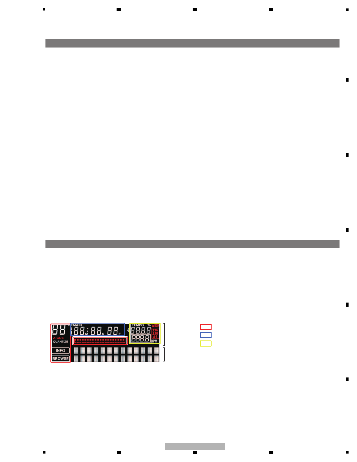
[2] Detailed specifications of each mode
• When the unit is powered on while pressing both the TIME and TEMPO RANGE button on DECK1 simultaneously,
this mode starts after [SERVICE MODE] is displayed for 2 seconds on the dot display.
• You can check whether buttons, knobs and displays are performed properly in this mode.
• In the dot display, TIME display mode is always shown in the upper row and the button names excluding the INFO/UTILITY
button light up in the lower row while they are pressed.
• TIME display mode starts from the DECK VOL display mode.
• When the TEMPO slider is moved far down to the [+] side during this mode, the mode is switched to JOG dial load
measurement mode.
Dot display
Time display
: (1)
: (2)
: (3)
1. MODE to check buttons and displays
6 7 8
6. SERVICE MODE
6.1 SERVICE MODE
A
B
C
D
E
F
XDJ-R1
5
6 7 8
21
Page 22
1
TEMPO RANGE
TEMPO indicator
—————TEMPO RANGE button
MASTER TEMPO MASTER TEMPO indicator —————MASTER TEMPO button
MASTER MASTER indicator —————MASTER button
SYNC SYNC indicator —————SYNC button
TIME/ACUE ————— —————
TIME (AUTO CUE, QUANTIZE) button
DECK, MIXER1, MIXER2
(Toggle DECK, MIXER1 or MIXER2)
————— Switch to TIME display mode.
DECK: DECK VOL mode
MIXER1 & MIXER2: Mixer VOL mode
These are always displayed in the upper
row of the dot display.
INFO (UTILITY) button
————— AllLED light up. All VFD light up.BACK (TOP) button
DISC h DISC h indicator —————DISC h button
USB WLAN indicator (1) are all light up. USB button
CD CD indicator (2) are all light up. CD button
MIDI MIDI indicator (3) are all light up. MIDI button
USB STOP USB STOP indicator —————USB STOP button
0 to FF (in TRACK of TIME display)
—————
Always displayed on the TIME display VFD.
AUTO BEAT LOOP control (Turn)
AUTO BEAT AUTO BEAT LOOP indicator —————AUTO BEAT LOOP control (Press)
0 to FF (in MIN of TIME display)
—————
Always displayed on the TIME display VFD.
BEAT control (Turn)
BEAT BEAT indicator —————BEAT control (Press)
0 to FF (in SEC of TIME display)
—————
Always displayed on the TIME display VFD.
LEVEL/DEPTH control (Turn)
TA P
TAP indicator —————TAP button
0 to FF (in FRAME of TIME display)
—————
Always displayed on the TIME display VFD.
Rotary selector (SELECT PUSH) (Turn)
PUSH
————— —————
Rotary selector (SELECT PUSH) (Press)
TOUCH
JOG illumination —————JOG dial TOUCH SENSOR
JOG d
————— —————JOG dial turn (clockwise)
c JOG
————— —————JOG dial turn (counterclockwise)
VINYL VINYL MODE indicator —————VINYL MODE button
* Check the operation of TEMPO SLIDER by normal startup.
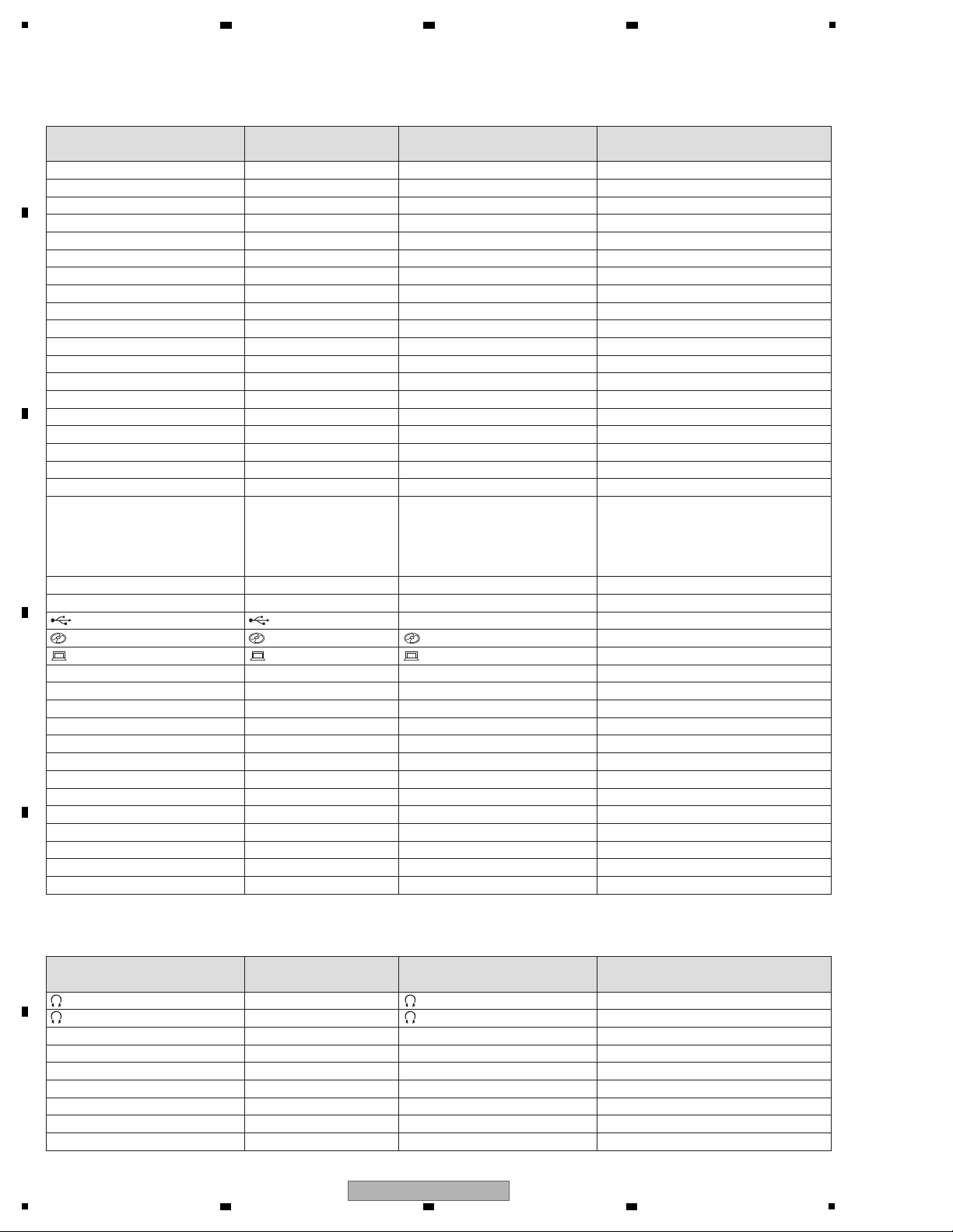
DECK area
Characters shown
on the display
Lit-up LED Note/RemarksButtons and volume knobs
PLAY d d/e (PLAY/PAUSE) indicator —————d/e (PLAY/PAUSE) button
CUE
CUE indicator —————CUE button
SHIFT SHIFT indicator —————SHIFT button
TRACK o
TRACK SEARCH (o) indicator
—————TRACK SEARCH (o) button
TRACK SEARCH p
TRACK SEARCH (p) indicator
—————TRACK SEARCH (p) button
MODE MODE indicator —————MODE button
CALL
CALL indicator —————CALL button
HOT CUE A
HOT CUE/4-BEAT SAMPLER (A) indicator
—————
HOT CUE/4-BEAT SAMPLER (A) button
HOT CUE B
HOT CUE/4-BEAT SAMPLER (B) indicator
—————
HOT CUE/4-BEAT SAMPLER (B) button
HOT CUE C
HOT CUE/4-BEAT SAMPLER (C) indicator
—————
HOT CUE/4-BEAT SAMPLER (C) button
TRANS
BEAT FX (TRANS) indicator —————BEAT FX (TRANS) button
FLANGER
BEAT FX (FLANGER) indicator
—————BEAT FX (FLANGER) button
ECHO
BEAT FX (ECHO) indicator —————BEAT FX (ECHO) button
ROLL
BEAT FX (ROLL) indicator —————BEAT FX (ROLL) button
MIXER area
Characters shown
on the display
Lit-up LED Note/RemarksButtons and volume knobs
HP CUE CH1 (CH1) indicator ————— (CH1) button
HP CUE CH2 (CH2) indicator ————— (CH2) button
AUX AUX (ON/OFF) indicator —————AUX (ON/OFF) button
MIC MIC (ON/OFF) indicator —————MIC (ON/OFF) button
USB STOP USB STOP indicator —————USB STOP button
PITCH
SOUND COLOR FX (PITCH) indicator
—————
SOUND COLOR FX (PITCH) button
FILTER
SOUND COLOR FX (FILTER) indicator
—————
SOUND COLOR FX (FILTER) button
NOISE
SOUND COLOR FX (NOISE) indicator
—————
SOUND COLOR FX (NOISE) button
CRUSH
SOUND COLOR FX (CRUSH) indicator
—————
SOUND COLOR FX (CRUSH) button
A
B
C
D
E
2 3 4
F
22
1
XDJ-R1
2 3 4
Page 23
MIXER area
Switching to the TIME display mode
Each time INFO (UTILITY) button is pressed, the TIME display mode is switched to show the values of VOL, Fader, etc.
of the MIXER area.
The display modes to be shown when INFO (UTILITY) button is pressed are listed below.
DECK VOL display mode → MIXER VOL display mode 1 → MIXER VOL display mode 2 → DECK VOL display mode → • • •
Characters shown
on the display
Lit-up LED Note/RemarksButtons and volume knobs
————— LEVEL indicator (CH1)
(+9 dB, +4 dB)
Relationship between select position
and LED is as follows:
Left: +9 dB, Right: +4 dB
DECK1, PHONO1, LINE1
selector switch
————— LEVEL indicator (CH2)
(+9 dB, +4 dB)
Relationship between select position
and LED is as follows:
Left: +9 dB, Right: +4 dB
DECK2, PHONO2, LINE2
selector switch
————— LEVEL indicator (CH1)(-12 dB) Relationship between select position
and LED is as follows:
0 dB: -6 dB, 12 dB: -12 dB
LINE, POTABLE PLAYER
selector switch
————— LEVEL indicator (CH1)
(+2 dB, 0 dB)
Relationship between select position
and LED is as follows:
PHONO: +2 dB, LINE: 0 dB
LINE, PHONO selector switch
(CH1)
————— LEVEL indicator (CH2)
(+2 dB, 0 dB)
Relationship between select position
and LED is as follows:
PHONO: +2 dB, LINE: 0 dB
LINE, PHONO selector switch
(CH2)
————— LEVEL indicator (CH2)
(-6 dB, -12 dB, -18 dB)
Relationship between select position
and LED is as follows:
Left: -6 dB, Middle: -12 dB, Right: -18 dB
CROSS F. CURVE ( , , )
(crossfader curve selector switch)
MIXER VOL display mode 1
[CH1]
Characters shown on the display Lit-up LED Note/RemarksButtons and volume knobs
0 to FF (in TRACK of TIME display) ————— Always on TIME display VFD.TRIM control
0 to FF (in MIN of TIME display) ————— Always on TIME display VFD.EQ (HI) control
0 to FF (in SEC of TIME display) ————— Always on TIME display VFD.EQ (MID) control
0 to FF (in FRAME of TIME display) ————— Always on TIME display VFD.EQ (LOW) control
0 to FF (in TEMPO number display) ————— Always on TIME display VFD.COLOR control
MIXER VOL display mode 2
Characters shown on the display
Lit-up LED Note/RemarksButtons and volume knobs
0 to FF (in TRACK of TIME display) ————— Always on TIME display VFD.HEADPHONE MIXING control
0 to FF (in MIN of TIME display) ————— Always on TIME display VFD.HEADPHONE LEVEL control
0 to FF (in SEC of TIME display) ————— Always on TIME display VFD.MASTER LEVEL control
0 to FF (in FRAME of TIME display) ————— Always on TIME display VFD.BOOTH MONITOR control
0 to FF (in TEMPO number display) ————— Always on TIME display VFD.Channel fader (CH1)
MIXER VOL display mode 1
[CH2]
Characters shown on the display Lit-up LED Note/RemarksButtons and volume knobs
0 to FF (in TRACK of TIME display) ————— Always on TIME display VFD.TRIM control
0 to FF (in MIN of TIME display) ————— Always on TIME display VFD.EQ (HI) control
0 to FF (in SEC of TIME display) ————— Always on TIME display VFD.EQ (MID) control
0 to FF (in FRAME of TIME display) ————— Always on TIME display VFD.EQ (LOW) control
0 to FF (in TEMPO number display) ————— Always on TIME display VFD.COLOR control
MIXER VOL display mode 2
Characters shown on the display Lit-up LED Note/RemarksButtons and volume knobs
0 to FF (in TRACK of TIME display) ————— Always on TIME display VFD.AUX LEVEL control
0 to FF (in MIN of TIME display) ————— Always on TIME display VFD.MIC LEVEL control
0 to FF (in SEC of TIME display) ————— Always on TIME display VFD.MIC EQ control
0 to FF (in FRAME of TIME display) ————— Always on TIME display VFD.Crossfader
0 to FF (in TEMPO number display) ————— Always on TIME display VFD.Channel fader (CH2)
5
6 7 8
A
B
C
D
E
F
5
6 7 8
XDJ-R1
23
Page 24
1
• When the TEMPO slider is moved far down to the [+] side during the button and function checking mode, the mode is
switched to the JOG dial load measurement mode to show the Max speed and time in the dot matrix.
•
When the JOG dial is swiftly rotated, the figures are displayed. The jog dial can be rotated either clockwise or counterclockwise.
• For example, when "8.6: 115" is shown on the display, which indicates as follows:
X 8.6: Maximum speed (X1 is defined as 1.8 second required for one revolution.)
115: Time (msec) required to lower the revolution speed from X3 to X1.5
• In order to measure the time to lower the rotation speed, the maximum speed of the jog wheel should be X7.0 or more.
• When time is measured several times in a row, up to the fourth largest msec among the several times of measurement other
than the first one is averaged.
• When the unit is powered on while the TIME and HOT CUE A buttons of DECK 1 are pressed simultaneously, this mode
starts after the "TEST MODE" is displayed in the dot display area.
• This mode is comprised of the following 2 modes:
CD drive performance mode
• Mode to measure servo's basic actions such as set up, play, pause and track search and error rate.
• Before the CD drive diagnostic mode starts, this mode is first displayed.
Test performance mode
• This mode can precisely control servo's actions step by step.
* Commands in this diagnostic mode are for testing mainly the mechanism and servo systems but not for testing
the DJ functions, such as SCAN and TEMPO.
Commands of the CD drive performance mode
Play (trace) / Pause (d/e (PLAY/PAUSE))
• If the CD drive is in stopped state, it is set up to start playback.
• When a track is playing, each time the button is pressed, the track is alternately paused and played.
• The current playing address is displayed in the time display.
Track Search F/R (TRACK SEARCH o, p)
• A track displayed is searched clockwise or counterclockwise and paused.
Eject (DISC h)
• A Disc is ejected.
Mode Change (MASTER TEMPO)
• When the MASTER TEMPO button is pressed in the CD drive performance mode, the MASTER TEMPO's LED lights up
and shifted to Test performance mode.
3. JOG dial load measurement mode
4. CD drive diagnostic mode
Max speed
0. 0 :
0ms
Time (msec)
Buttons on the unitFunction
d/e (PLAY/PAUSE)
TRACK SEARCH o, p
DISC h
MASTER TEMP
<CD drive performance mode>
Play (trace) / Pause
Track Search F/R
Eject
Mode Change
Buttons on the unitFunction
INFO (UTILITY)
TEMPO
BEAT FX (TRANS)
BEAT FX (FLANGER)
BEAT FX (ECHO)
TRACK SEARCH p
TRACK SEARCH o
BEAT FX (ROLL)
MASTER TEMPO
<Test performance mode>
Servo All Off (Stop)
LD On/Off
Focus On
Spindle Kick, Tracking On/Off
Tracking Off
Slide FWD (2 mm)
Slide REV (2 mm)
Pickup Up/Down
Mode Change
A
2 3 4
B
C
D
E
F
24
XDJ-R1
1
2 3 4
Page 25

5
Commands of Test performance mode
This mode can precisely control servo's actions step by step.
Cautions for the usage of the Test performance mode because it could damage the CD drive if it is not used properly.
Servo All Off (INFO (UTILITY))
• When the INFO (UTILITY) button is pressed while servo is on, all the servo is off and [ALL OFF] is displayed
on the dot display area.
LD On/Off (TEMPO)
• When the TEMPO button is pressed, LD (Laser diode) is alternately turned on and off and [LD ON] or [LD OFF]
is displayed in the dot display area.
Focus On (BEAT FX (TRANS))
• When the BEAT FX (TRANS) button is pressed during PAUSE, LD is turned on and automatically focused and [FCS ON]
is displayed in the dot display area.
Spindle Kick, Tracking On/Off (BEAT FX (FLANGER))
• When the BEAT FX (FLANGER) button is pressed while tracking servo is off, spindle kick is performed, auto adjustment
and tracking servo are turned on and [TRK ON] is displayed in the dot display area.
• When the BEAT FX (FLANGER) button is pressed while tracking servo is on, tracking servo is turned off and [TRK OFF]
is displayed in the dot display area.
Tracking Off (BEAT FX (ECHO))
• When the BEAT FX (ECHO) button is pressed while tracking servo is on, tracking servo is turned off and [TRK OFF] is
displayed in the displayed in the dot display area.
Slide FWD (TRACK SEARCH p)
• When the TTRACK SEARCH p button is pressed while tracking servo is on, tracking servo is turned off and the slider is
moved approximately 2 mm in FWD direction and [SLD FWD] is displayed in the dot display area.
Slide REV (TRACK SEARCH o)
• When the TRACK SEARCH o button is pressed while tracking servo is on, tracking servo is turned off and the slider is
moved approximately 2 mm in REV direction and [SLD REV] is displayed.
Pickup UP/DOWN (BEAT FX (ROLL))
• When the BEAT FX (ROLL) button is pressed during STOP, LD is turned on, the pick-up is moved up and down with the
focus continued, and [PU UP/DN] is displayed in the dot display area.
Mode Change (MASTER TEMPO)
• When the MASTER TEMPO button is pressed in Test performance mode, MASTER TEMPO LED is turned off and
shifted to PLAYER performance mode.
* To start up the unit in Test mode in steps, input the commands in the following order: "Servo All Off," "Focus On,
" then “Spindle Kick, Tracking On."
• When the MODE (HOT CUE/4-BEAT SAMPLER) button is pressed and held for approximately 10 seconds in the normal
usage conditions, this mode starts and the current version is displayed in the dot display area.
• When the CALL button is pressed, the following versions are toggled to be displayed.
5. Version checking mode
(1) Ver. 1.00 SYSTEM version
↓
(2) DSP 1.00 DSP version
↓
(3) SERVO 1.00 SERVO version
↓
(4) MIXER 1.00 MIXER version
↓
(5) CON 1.00 UI version
↓
(6) VFD 1.00 VFD version
6 7 8
A
B
C
D
XDJ-R1
5
6 7 8
E
F
25
Page 26

1
• When the TRACK SEARCH p or o button is pressed while the version of SYSTEM is displayed, the latest 16 errors
in history are shown.
• MEDIA name (USB/CD) where an error occurs is displayed in the upper row of the dot display and the error number is in the
lower row.
• The history can be reset by performing Factory Reset.
6. Error history display mode
Error numbers to be memorized
Table. Which VR is displayed
Error name Error detailsError No.
CANNOT READ DISC TOC data cannot be read. E-7201
CANNOT PLAY TRACK Buffer under-run error.E-8303
UNSUPPORTED FILE FORMAT MP3 DECODE ERROR.E-8304
UNSUPPORTED FILE FORMAT UNSUPPORTED FILE.E-8305
MECHANICAL TIME OUT Mechanical error in disc loading (Time out).E-9101
CANNOT PLAY TRACK • Failed the search of the address you are looking for.
• Cannot read the address.
• FILE OPEN ERR.
E-8302
CANNOT READ DISC • Failed to search the address you are looking for.
• Cannot read the address.
• Cannot close the focus servo.
• Pickup does not return to the inner perimeter.
E-8301
• When the unit is powered on while the TIME and HOT CUE B buttons of DECK 1 are pressed simultaneously, this mode
starts (STEP No. 0).
7. displaying A/D values mode
Step DetailNo.
Select the mode. Start the mode of displaying A/D values.0
A
CH1 FL
PITCH1_1
CH2 FL
PITCH2_1
B PITCH1_2 PITCH2_2
C DEPTH_1 DEPTH_2
D CH1_TRIM CH2_TRIM
E CH1_HI CH2_HI
F CH1_MID CH2_MID
G CH1_LOW CH2_LOW
H CH1_FILTER CH2_FILTER
I CH1_FADER CH2_FADER
J H.P.LEVEL AUX LEVEL
K H.P..MIXING MIC LEVEL
L CROSS FADER MIC EQ
M MASTER LEVEL BOOTH MONITOR
Start measuring. Press the SYNC button, SYNC indicator lights up, and Start measuring.1
Finish measuring.
Maximum valueThe VR name that is indicated
Press the SYNC button, SYNC indicator lights off, and finish measuring.5
Set the initial value. About all VRs
Stores the average of 8 times value that was read at this time. This is the initial value.
FL display is shown in the table below will change A, B, C......M, A, B,... By clockwise rotation.
By counterclockwise rotation, M,L,K,......A,M,...
2
measuring. About all VRs
Reading the value (absolute value) of the difference between the initial value stored in the "2",
and stores the largest.
3
Check measurements.
Rotate "SELECTOR",
FL (CH1) display the name of VR (PITCH1_1) and the maximum value of VR "PITCH1_1" that stored in the "3".
FL (CH2) display the name of VR (PITCH2_1) and the maximum value of VR "PITCH2_1" that stored in the "3".
4
A
2 3 4
B
C
D
E
F
26
1
2 3 4
XDJ-R1
Page 27

5
• When DECK1 is powered on while the TIME and BACK buttons are simultaneously pressed, [ERASE] is displayed in the dot
display.
The following settings are reset to factory default or all cleared.
• The letters of [ERASE] are continuously displayed until the power is turned off.
UTILITY settings (DECK1 and 2)
Wi-Fi related: It is the same as that of the case where YES
of UTILITY (WLAN) RESET TO DEFAULT is chosen.
MIXER MODE : XDJ-R1
A.CUE LEVEL : -60 dB
SAMPLE LEVEL : 50
CROSS FADER START : OFF
TOUCH SENSE LEVEL (DECK1) : 0
TOUCH SENSE LEVEL (DECK2) : 0
AUTO STANDBY : 20 min
DEMO MODE : OFF
Clear all
ERR History
DISC MEMORY HOT CUE
SAMPLER
DECK settings (DECK1 and 2)
TIME MODE : REMAIN
AUTO CUE : OFF
TEMPO RANGE : ±10 %
MASTER TEMPO : OFF
QUANTIZE : ON
Vinyl MODE : OFF
HOT CUE/SAMPLER MODE : HOT CUE
9. Factory reset
Refer to "8.2 UPDATING OF THE FIRMWARE".
10. FIRMWARE UPDATE
The center position of a knob is determined by Power ON, using the position of a center click of the following knobs
and pushing the TIME and TRACK SEARCH p buttons of DECK1 and DECK2.
Before performing center setting, be sure to set the controls to their center positions.
EQ (HI, MID, LOW)
COLOR
HEADPHONES MIXING
LEVEL/DEPTH
MIC EQ
8. Center setting for the controls
6 7 8
A
B
C
D
E
F
XDJ-R1
5
6 7 8
27
Page 28

1
A
100-COMBO-2962
×6
A
A AA A
A
E
Black
White White
White White
Black
Black
White
White
Gray Black
B D DB
C
B
B
100-DJM100-2826-HA
×4
C
100-DJM250-2826-HA
×15
D
100-CMX4-2906-HA
×2
E
100-22-2824-HA
×3
Knobs and Volumes Location
Note:
(1) Do NOT look directly into the pickup lens. The laser beam may cause eye injury.
(2) Even if the unit shown in the photos and illustrations in this manual may differ from your product, the
procedures described here are common.
2 3 4
7. DISASSEMBLY
A
B
C
D
E
F
28
XDJ-R1
1
2 3 4
Page 29

Disassembly
[1] Control Panel Section
(1) Remove the four screws.
(602-ISO308-735B)
(2) Remove the 11 screws.
(602-DJ3000-272)
(3) Remove the Control panel Section.
(4) Disconnect the three flexible cables and three
connectors.
(CN200, 209, 210, 804, 812A, 812B)
1
1
7
8
4
5
6 9
10
11
2
3
2 3 4
Screw tightening order
• Rear view
• Bottom view
1 1 1 1
2
2
2
2
3
2
2
2
2
2
2
2
Control panel Section
MIXER Assy
DSP & POWER Assy
×3
4
×3
4
CN804
CN200
CN210
CN209
CN812A
CN812B
5
6 7 8
A
B
C
D
E
XDJ-R1
5
6 7 8
F
29
Page 30

1
[2] Wi-Fi PCB, DSP & POWER, I/O, PHONES Assemblies SWITCHING POWER and
SLOT-IN FEEDER MECHA Assy
[2-1] Wi-Fi PCB and DSP & POWER Assemblies
(1) Remove the Wi-Fi PCB Assy by removing the
four screws.
(602-DJ5500-452)
(2) Release the clamp by removing the one screw.
(602-SA12-380)
(3) Disconnect the one flexible cable and five
connectors.
(CN2 to 6, 810)
(4) Remove the DSP & POWER Assy by removing
the five screws.
(602-SA12-380)
(5) Remove the solder of jumper wire.
(W402B)
1
1
1
3
4
2
4
4
4
4
333
3
3
1
DSP & POWER Assy
SWITCHING POWER
Wi-Fi PCB Assy
CN810
CN5
CN6
CN2
CN3
CN4
5
W402B
[2-2] SLOT-IN FEEDER MECHA Assy
(1) Remove the 12 screws.
(602-DJ5500-452)
(2) Remove the two SLOT-IN FEEDER MECHA
Assemblies.
[2-3] SERVO Assy
(1) Disconnect the one flexible cable and two
connectors.
(CN101, 105, 106)
(2) Remove the four screws.
(602-DD2220-301)
(3) Remove the SERVO Assy.
1 1
1
1
1
1
1
2
2
2
2
3
1
1
1
1
1
I/O Assy
SLOT-IN FEEDER
MECHA Assy (DECK1)
SLOT-IN FEEDER
MECHA Assy (DECK2)
SERVO Assy
1
1
1
CN106
CN101
CN105
2 2
• Bottom view
A
2 3 4
B
C
D
E
F
30
1
2 3 4
XDJ-R1
Page 31

5
(2) Remove the four screws.
(3) Remove the top cover.
Caution:
Work not to transform two springs.
2
2
2 2
Top cover
Top cover Pickup lens
3
• Cleaning
(1) Turn the gear to the arrow direction of the
figure with finger.
(Pickup moves to a periphery.)
SERVO Assy
Gear
Pickup
1
1
• Bottom view
Cleaning the pickup lens
Clean the pickup lens when it is stained, using
the following cleaning materials:
Cleaning liquid : GEM1004
Cleaning paper: GED-008
Caution Caution
6 7 8
A
B
C
D
5
XDJ-R1
6 7 8
E
F
31
Page 32

1
• Method to perform forced ejection of a disc
Turn the gear pulley to the arrow direction of the
figure with finger.
The disc comes out when you continue turning
gear pulley.
Pull out the disc out by hand.
Disc
Disc
Gear pulley
Gear pulley
Gear pulley
A
B
2 3 4
C
D
E
F
32
XDJ-R1
1
2 3 4
Page 33

[2-4] I/O Assy
• Rear board Assy Section
• I/O Assy
(1) Remove the two screws.
(602-ISO308-735B)
(2) Disconnect the two flexible cables.
(CN808, 809)
(3) Remove the two screws.
(602-DJ5500-452)
(4) Remove the seven screws.
(602-DJ5500-452)
(5) Disconnect the one connector.
(CN1)
(6) Remove the ferrite core by removing the one
screw.
(602-SA12-380-HA)
(7) Remove the ferrite core by removing the one
screw.
(602-MK7-131-HA)
(8) Remove the jumper wire by removing the
eight screws.
(602-DV300-5023)
(9) Remove the Rear board Assy Section.
1
4 4
4
3
3
2
4444
8
6
8
8
8
8
8 8
8
9
7
1
Rear board Assy Section
I/O Assy
2
CN808
CN1
CN809
• Rear view
5
(1) Remove the one nut.
(2) Remove the one screw.
(602-DD2220-301)
(3) Remove the one screw, one nut and one washer.
(602-ISO308-735B)
(4) Remove the two screws.
(602-ISO308-735B)
(5) Remove the eight screws.
(602-PTS308-732B)
(6) Remove the two screws.
(602-SA12-377)
(7) Remove the one screw.
(602-SA12-380)
(8) Remove the I/O Assy.
1
5
5
5
5
6
6
4
4
7
8
2
3
I/O Assy
• Rear view
12
3 5
4 6
7 8 9
10
Screw tightening order
The other screws are random order.
×5
Bisogna smontare anche le 2 meccaniche
5
6 7 8
A
B
C
D
E
5
XDJ-R1
6 7 8
F
33
Page 34

1
• Rear view
• Rear view
2 1 3
Screw tightening order
[2-5] SWITCHING POWER
(1) Disconnect the three connectors.
(CN1 to 3)
(2) Remove the SWITCHING POWER by removing
the six screws.
(602-DJ5500-452)
Note:
When you remove SWITCHING POWER, it is not
necessary to remove the other PCB Assemblies.
[2-6] PHONES Assy
(1) Disconnect the one connector.
(CN401)
(2) Release the jumper wires.
(3) Release the jumper wires by removing the
two screws.
(602-DV300-5023)
(4) Remove the Front panel Assy Section by
removing the 10 screws.
(602-SL24F-099)
(5) Remove the PHONES Assy by removing
the three screws.
(602-DV300-5023)
Note:
When you remove PHONES Assy, remove
SLOT-IN FEEDER MECHA Assy first.
1
1
1
2
2
3
3
4
2
2
2
2
2
SWITCHING POWER
PHONES Assy
I/O Assy
PHONES Assy
Front panel Assy Section
CN1
CN401
CN2
CN3
1
×10
5
×3
A
B
2 3 4
C
D
E
F
34
1
XDJ-R1
2 3 4
Page 35

5
[3] Jog dial Section
(This part is supplied in Assy, and after that be
reference information.)
(1) Remove the one E ring.
(2) Remove the Wheel & shaft Assy.
(3) Remove the one washer.
(4) Remove the Wheel plate.
(5) Remove the Spring by removing the one screw.
(602-STS2003-677)
(6) Remove the Wheel ring Assy by removing the
six screws.
(602-A700-494)
(7) Remove the Wheel reactor by removing the
six screws.
(602-A700-494)
Note:
A figure is only left DECK side, but the right side
is similar, too.
• Bottom view
4
5
1
2
3
6
×6
7
×6
Wheel & shaft Assy
Washer
Wheel plate
Spring
Wheel outer ring
Wheel ring Assy
Wheel reactor
1
1
2
2
3
3
4
4
5
5
6
6
Screw tightening order
6 7 8
A
B
C
D
E
XDJ-R1
5
6 7 8
F
35
Page 36

1
[4] Fader Section, MIXER, USB and CD Assemblies
[4-1] Fader Section
(1) Remove the all knobs.
(2) Remove the Mixer panel Assy by removing the
seven screws.
(602-PTF2609-710B)
1
×30
2
2
2
2
2
2 2
Mixer panel Assy
1
2 3
6 7
5 4
Screw tightening order
Note: When you remove each PCB Assemblies, it is not necessary to remove the Jog dial Section.
(3) Remove the 17 nuts and 17 washers.
(4) Remove the Wi-Fi lens.
(5) Remove the two CH Assemblies by
removing the four screws.
(602-DJ5500-452)
(6) Disconnect the one connector.
(CN208)
(7) Remove the CH fixed plate by removing the
two screws.
(602-SA12-414)
(8) Remove the CROSS FADER Assy by removing
the two screws.
(602-SA12-380)
(9) Disconnect the one connector.
(CN01)
(10) Remove the Fixed plate by removing the
two screws.
(602-SA12-414)
CROSS FADER AssyCH Assy
Fixed plate
CH fixed plate
5
5
8 8
5
5
CROSS FADER Assy
CH Assy
Wi-Fi lens
7
6
9
×2
10
×2
CN208
CN01
3
4
×17
A
2 3 4
B
C
D
E
F
36
1
2 3 4
XDJ-R1
Page 37

5
[4-2] MIXER Assy
(1) Remove the one clip.
(2) Remove the Isolation slice by removing the
two screws.
(602-MK8-604)
(3) Disconnect the four flexible cables.
(CN201, 204, 206A, 206B)
(4) Remove the one screw and one washer.
(602-MK8-604)
(5) Remove the MIXER Assy by removing
the seven screws.
(602-MK8-604)
[4-3] USB Assy
(1) Remove the USB Assy by removing
the three screws.
(602-MK8-604)
1
2 2
1
1
1
1
5
66
6
6
1
3
3
2
2
2
2
4
4
Isolation slice
CD2 Assy CD1 Assy
MIXER Assy
3
3
4
3
3
CN206B
CN206A
CN201
CN204
CN206
CN201
CN206
CN204
5
×7
1
×3
7
×20
7
×23
[4-4] CD Assy
(1) Remove the two Segregate sheets by
removing the five screws.
(602-MK8-604)
(2) Disconnect the four flexible cables.
(CN201, 204, 206)
(3) Remove the two solders.
(4) Remove the two screws and two washers.
(602-MK8-604)
(5) Release the jumper wires.
(6) Remove the four screws.
(602-MK8-604)
(7) Remove the CD1 and 2 Assemblies by
removing the 43 screws.
(602-MK8-604)
• Bottom view
• Bottom view
• Bottom view
USB Assy
Segregate sheet Segregate sheet
Note:
When you remove CD1 and 2 Assemblies,
it is not necessary to remove the MIXER Assy.
6 7 8
A
B
C
D
5
6 7 8
XDJ-R1
E
F
37
Page 38

1
The Application Position of Adhesive and Grease
• Bottom view
DSP & POWER Assy
I/O Assy
Bottom
side
Bottom
side
Bottom
side
Bottom
side
Bottom
side
SLOT-IN FEEDER
MECHA Assy
SERVO Assy
Adhesive
(GYL1005)
Silicon bond
(GYA1011)
Adhesive
(GYL1005)
Adhesive
(GYL1005)
Adhesive
(GYL1001)
Adhesive
(GYL1001)
Adhesive
(GYL1001)
Adhesive
(GYL1001)
Adhesive
(GYL1001)
Adhesive
(GYL1001)
Chassis Assy
Grease
(GEM1072)
Wheel & shaft Assy
Grease
(GEM1072)
• Bottom view
CH fixed plate
Fixed plate
Adhesive
(GYL1001)
2 3 4
A
B
C
D
E
F
38
1
XDJ-R1
2 3 4
Page 39

5
CH1
CH2
EQ-LOWVR200
EQ-MID VR204
EQ-HI VR205
COLOR
EQ-LOW
EQ-MID
EQ-HI
COLOR
HEADPHONES MIXING
VR217
VR208
PLAYER1
LEVEL/DEPTH VR100
PLAYER2
LEVEL/DEPTH VR100
VR215
VR213
VR216
VR202
MIC EQ VR209
Ref No.
MIXER Assy
CD1 Assy
CD2 Assy
PCB Assy
VR Name
Please update firmware to the latest version at the repair necessarily.
Perform the each item when the following parts are replaced.
* The VRs with center click positions are listed below.
• Confirmation of the version of the firmware
• Updating to the latest version of the firmware
• IC storing firmware and PCB Assy
* The firmware storage IC information is as follows.
• Confirmation of the specified value by the JOG dial
load measurement mode
• When replaced WHEEL Assy
• Perform "8. Center setting for the controls"
in "6. SERVICE MODE."
• VRs with center click positions
DSP (DSP Version) DSP & POWER AssyDSP IC (Flash ROM) IC803
SERVO (SERVO Version)
I/O Assy
SERVO/MIXER IC
(CD MCU)
IC812
MIXER (MIXER Version)
CON (UI Version)
MIXER Assy
CONTROL IC (UI MCU) IC200
VFD (VFD Version) VFD IC (VFD MCU) IC207
Target Firm ware PCB Assy
Storage IC
Device Name Ref No.
After the IC812 (SERVO/MIXER IC), I/O Assy, or Wi-Fi PCB Assy is replaced, the SSID will be changed.
(As for the Wi-Fi PCB Assy, the SSID will be changed when resetting to factory default is performed after replacement.)
When returning the repaired product to the customer, be sure to tell the customer that resetting of the wireless LAN
connection will be required.
6 7 8
8. EACH SETTING AND ADJUSTMENT
8.1 NECESSARY ITEMS TO BE NOTED
A
B
C
D
E
XDJ-R1
5
6 7 8
F
39
Page 40

1
1 Download the zipped updater file for the latest firmware from Niis.
2 Unzip the downloaded file.
Unzipping the ZIP file generates the "XDJ-R1Vxxx.bin". (xxx: version number)
3 Copy an unzip file to a root folder of USB device.
Use USB device formatted in FAT/FAT32.
[Preparations]
1 The unit where no MEDIA is inserted is powered on while the USB and SHIFT and USB STOP button of DECK 1 are
pressed.
The buttons should be continuously pressed until [download] is displayed in the dot display area.
2 The firmware is copied to a USB device formatted to FAT/FAT32 and inserted to the unit.
Note: Be sure not to store multiple updater files in one USB device.
3 The following display is shown during the update.
4 After updating is completed, turn the unit off, unplug the USB device, then turn the unit back on.
5 Check in Version Check mode of Service mode to verify that updating succeeded.
* A version down is possible.
[Procedure]
Firmware update recovery when it is failed:
• If the firmware update is failed in such a case as turning off the power in the middle of the update, any subsequent control is
not available.
• When Error code E-7024 appears, recovery mode starts to continue the update again if appropriate USB update procedures
are taken.
DOWNLOAD MODE
Update progress is displayed in Playing Address Section.
When the update is completed, the following display appears.
2 3 4
8.2 UPDATING OF THE FIRMWARE
A
B
C
D
E
F
40
XDJ-R1
1
2 3 4
Page 41

5
The following setting is stored to an applicable IC.
Item for Which User's
Setting is Available
Part Name
UTILITY settings
MODE
ENABLE / DESABLE
ENABLE / DESABLE
XDJ-R1 / PC
1 — 50 — 100
ON / OFF
ON / OFF
-4 — 0 — +4
-4 — 0 — +4
OFF / 20 min / 40 min / 60 min
OPEN / WEP64 / WEP128
CH1 — 11, AUTO
A to Z, a to z, 0 to 9, symbols
(max. 32 characters)
A to Z, a to z, 0 to 9, symbols
(5 characters for [WEP64], 13 characters for [WEP128])
–36 dB / –42 dB / –48 dB / –54 dB /
–60 dB / –66 dB / –72 dB / –78 dB
Content to be
Stored
WLAN
SETTING
NETWORK
SETTING
SSID
SECURITY
PASSWORD
CHANNEL NO.
DHCP SERVER
MIXER MODE
SAMPLE LEVEL
CROSS FADER START
TOUCH SENSE LEVEL (DECK1)
TOUCH SENSE LEVEL (DECK2)
AUTO STANBY
DEMO MODE
A. CUE LEVEL
Setting Value (The factory default
settings are indicated in bold.)
IC812
(I/O Assy)
DECK settings
TIME / REMAINTIME MODE
ON / OFFAUTO CUE
WIDE, ±16, ±10, ±6TEMPO RANGE
ON / OFFMASTER TEMPO
ON / OFFVinyl MODE
HOT CUE / SAMPLERHOT CUE/SAMPLER MODE
ON / OFFQUANTIZE
8.3 USER SETABLE ITEMS
6 7 8
A
B
C
D
E
F
XDJ-R1
5
6 7 8
41
Page 42

1
NOTES: - Parts marked by “NSP” are generally unavailable because they are not in our Master Spare Parts List.
-
The > mark found on some component parts indicates the importance of the safety factor of the part.
Therefore, when replacing, be sure to use parts of identical designation.
-
Screws adjacent to b mark on product are used for disassembly.
-
For the applying amount of lubricants or glue, follow the instructions in this manual.
(In the case of no amount instructions, apply as you think it appropriate.)
for SVWYXE8, CUXE,
KXE5, AXE5
for FLWPWXE
SVWYXE8,
FLWPWXE
only
SVWYXE8,
FLWPWXE
only
2 3 4
9. EXPLODED VIEWS AND PARTS LIST
A
9.1 PACKING SECTION
B
C
D
E
F
42
1
2 3 4
XDJ-R1
Page 43

5
6 7 8
(1) PACKING SECTION PARTS LIST
Mark No. Description Part No.
> 1Power Cord See Contrast table (2)
> 2Power Cord See Contrast table (2)
3 USB Cable 408-100UG-087
4 Smartphone Stand 703-COMBO-1395
Smartphone Stand Mount Screws
5
6 CD-ROM 429-COMBO-144
7 Read Before Use (Important)/ See Contrast table (2)
Quick Start Guide
8 Leaflet 502-XDR1-3270
9 Handle 100-SX-3017
200-BLACK-642
A
10 Handle Base 100-SX-3018
11 Polyform A 506-COMBO-645A
12 Polyform B 506-COMBO-645B
13 Paste Board 507-COMBO-3367
14 Gift Box See Contrast table (2)
15 Soft Bag 509-COMBO-319
16 Caution Sheet See Contrast table (2)
17 About SSIDs and Passwords 501-XJR1-2506
18 Label See Contrast table (2)
(2) CONTRAST TABLE
XDJ-R1/SVWYXE8, CUXE, FLWPWXE, KXE5 and AXE5 are constructed the same except for the following:
Mark No. Symbol and Description
> 1Power Cord
> 2Power Cord Not used Not used 409-COMBO-226 Not used Not used
7
Read Before Use (Important)/
Quick Start Guide
14 Gift Box 507-R1B-3401 507-R1A-3401 507-R1F-3401 507-R1E-3401 507-R1D-3401
16 Caution Sheet Not used Not used 502-XDR1F-3321 Not used Not used
18 Label 501-XJR1B-2576 Not used 501-XJR1B-2576 Not used Not used
XDJ-R1
/SVWYXE8
409-HDJ7100-055D-HA 409-HDJ7100-054D-HA 409-HDJ7100-055D-HA
502-XDR1B-3272 502-XDR1A-3271 502-XDR1F-3276 502-XDR1E-3275 502-XDR1D-3274
XDJ-R1
/CUXE
XDJ-R1
/FLWPWXE
XDJ-R1
/KXE5
409-COMBO-224 409-DMX101-218
XDJ-R1
/AXE5
B
C
D
E
F
XDJ-R1
5
6 7 8
43
Page 44

1
I
I
B
C
D
E
Wheel plate
(NSP)
Wheel outer ring
(NSP)
Spring
(NSP)
Wheel ring Assy
(NSP)
Accessories of VR
(NSP)
Wheel reactor
(NSP)
EVA sheet
(NSP)
EVA sheet
(NSP)
EVA sheet
(NSP)
Note:
EVA sheet and Gascket do not supply it for service parts.
These are put on service parts of PCB Assy.
EVA sheet
(NSP)
Screw (NSP)
Screw
(NSP)
9.2 EXTERIOR SECTION
A
B
2 3 4
C
D
E
F
44
1
2 3 4
XDJ-R1
Page 45

5
A
H
J
J
K
G
F
Note:
EVA sheet and Gascket do not supply it for
service parts.
These are put on service parts of PCB Assy.
Gascket
(NSP)
Gascket
(NSP)
Gascket
(NSP)
Ferrite core
(NSP)
Ferrite core
(NSP)
Safety label
(NSP)
6 7 8
A
B
C
D
E
F
5
6 7 8
XDJ-R1
45
Page 46

1
(1) EXTERIOR SECTION PARTS LIST
Mark No. Description Part No.
1 MIXER Assy 704-COMBO-A376
A
2 CH Assy 704-COMBO-A482
3 CROSS FADER Assy 704-COMBO-A499
4 USB Assy 704-COMBO-A381
5 PHONES Assy 704-COMBO-A379
2 3 4
No. Description Part No.
Mark
46 4P Wire 404-COMBO-3772
47 3P Wire
404-UJ300KM-3644-HA
48 28P FFC Cable 406-COMBO-1245
49 38P FFC Cable 406-COMBO-1249
50 36P FFC Cable 406-COMBO-1250
6 Wi-Fi PCB Assy 704-COMBO-A380
7 CD1 Assy 704-COMBO-A375
8 CD2 Assy 704-COMBO-A476
9 SERVO Assy 704-COMBO-A377
10 SWITCHING POWER 411-COMBO-887
B
11 SLOT-IN FEEDER MECHA Assy
704-MCU300-9997-HA
12 • • • • •
13 I/O Assy 704-COMBO-A378
14 DSP & POWER Assy 704-COMBO-A531
15 Rear Board Assy 703-COMBO-1377
> 16 AC Socket Assy 704-COMBO-A483
17 Cord Bush 100-SDJ2-2553
18 Cord Bush 100-K1-2682-HA
19 Ground Terminal 200-100U-527
C
20 Hexagon Pillar 200-COMBO-668
21 Isolation Plate 300-COMBO-2063
22 Isolation Plate 300-COMBO-2075
23 26P FFC Cable 406-COMBO-1244
24 24P FFC Cable 406-COMBO-1247
25 8P FFC Cable 406-COMBO-1248
26 24P FFC 406-COMBO-1255
27 Spacer Support 504-COMBO-302
28 Nut (M3*P0.5) 601-A100-004-HA
D
29 Fixed Center Washer 606-C426-066
30 Washer 606-4500-123
51 8P FFC Cable 406-COMBO-1251
52 28P FFC Cable 406-MEP4-1201-HA
53 Wire 406-S100-031
54 Ferrite Core 415-VP9812-221-HA
55 Mixer Panel Assy 703-XDJR1-1394
56 Chassis Assy 701-XDJR1-5329
57 Front Panel Assy 701-COMBO-5204
58 Base Assy See Contrast table (2)
59 Wheel & Shaft Assy 701-COMBO-5294
60 PLAY/CUE Button 701-XDJR1-5325
61 USB Button Assy 701-XDJR1-5326
62 Push Button 100-22-2824-HA
63 AUX Button 100-AUX-2975
64 Round Button 100-BLACK-2968S
65 CALL Button 100-CALL-2967A
66 Push Knob 100-CMX4-2906-HA
67 Color Button 100-COLOR-2973S
68 Encoder Knob 100-COMBO-2962
69 CUE Button 100-CUE-2974
70 Rotary Knob 100-DJM100-2826-HA
71 Rotary Knob
100-DJM250-2826-HA
72 Eject Button 100-EJECT-2970
73 HOTCUE Button 100-HOTCUE-2971S
74 MASTER Button 100-MASTER-2967A
75 MIC Button 100-MIC-2975
31 Nylon Washer 606-500C-265
32 Washer 606-COMBO-266
33 Washer 606-COMBO-267
34 Screw 602-B300-041-HA
35 Screw 602-DD2220-301-HA
36 Screw 602-SA12-377-HA
37 Screw 602-SA12-380-HA
E
38 Screw 602-ISOB408-543C
39 Screw 602-PTS308-732B
40 Screw 602-ISO308-735B
41 • • • • •
42 Electrical Tape 501-COMBO-2216
43 Canoe Clips (MB-1S) 504-HF6011-5011
44 Fixed Loop (2A-8) 504-COMBO-300
45 Spacer Support 504-QFX-204
F
46
1
2 3 4
XDJ-R1
76 MODE Button 100-MODE-2967A
77 Push Button 100-MX200-2706-HA
78 Round Button 100-ROUND-2968
79 Source Button 100-SOURCE-2966
80 SQUERE Button 100-SQUARE-2967
81 Push Button 100-SW-2980S
82 SYNC Button 100-SYNC-2967A
83 TAP Button 100-TAP-2969
84 TINY Button 100-TINY-2965S
85 TRACK Button 100-TRACK-2964
86 Wi-Fi Lens 100-WIFI-2979
87 Transfer Plate 300-COMBO-2034
88 Mecha Fixed Plate 300-COMBO-2036
89 CH Fixed Plate 300-COMBO-2038
90 Ground Plate L 300-COMBO-2064
Page 47

5
No. Description Part No.
Mark
91 Ground Plate R 300-COMBO-2065
92 Ground Plate L 300-COMBO-2066
93 Ground Plate R 300-COMBO-2067
94 Join Plate 300-COMBO-2072
95 Fixed Plate
300-DJM100-1960-HA
96 Cover 300-DMX101-1993
97 Locking Cable Clip 300-HM510B-224
98 Ground Plate 300-SPINU2-1692
99 Isolation Slice 501-COMBO-2554
100 Isolation Slice 501-COMBO-2555
6 7 8
A
101 Segregate Sheet 501-COMBO-2564
102 Segregate Sheet 501-COMBO-2568
103 Adhesive Mount 504-HDJ7000-032
104 Canoe Clips 504-HF6011-5011
105 Spring 603-C304-335
106 USB Cap 604-COMBO-605
107 E Ring 606-C304-209
108 Sponge 612-COMBO-462
109 • • • • •
110 • • • • •
111 Nut 601-A100-004-HA
112 Fixed Center Washer 606-C426-066
113 Washer 606-COMBO-264
114 Washer 606-COMBO-266
115 Washer 606-KMD280-081-HA
116 Washer 606-RMP25-257
117 Screw 602-A700-494-HA
118 Screw 602-DD2220-301-HA
119 Screw 602-DJ3000-272
120 Screw 602-DJ5500-452-HA
121 Screw 602-DV300-5023
122 Screw 602-H888F-308-HA
123 Screw 602-ISO308-735B
124 Screw 602-MK7-131-HA
125 Screw 602-MK8-604
B
C
D
126 Screw 602-PTF2609-710B
127 Screw 602-SA12-380-HA
128 Screw 602-SA12-414
129 Screw 602-SL24F-099
130 Screw 602-ST150-431
(2) CONTRAST TABLE
XDJ-R1/SVWYXE8, CUXE, FLWPWXE, KXE5 and AXE5 are constructed the same except for the following:
Mark No. Symbol and Description
58 Base Assy 701-COMBO-5206 701-COMBO-5205 701-COMBO-5340 701-COMBO-5339 701-COMBO-5338
5
XDJ-R1
/SVWYXE8
6 7 8
XDJ-R1
/CUXE
XDJ-R1
XDJ-R1
/FLWPWXE
XDJ-R1
/KXE5
E
XDJ-R1
/AXE5
F
47
Page 48

1
3
2
1
L
R
JK407A
AUX
L
3
R
2
G
1
S
4
JK408
MIC
AV=-9.05dBAV PH=36dB
3
2
1
L
R
JK402
LINE1
SCK 3A
DO6
LIN
1
RIN
2
VREF1
3
VREF2
4
VCC
5
AGND
6
PDWN
7
BYPAS
8
TEST
9
LRCK10BCK
11
DOUT
12
DGND
13
VDD
14
SCK 1
15
OSR
16
FMT0
17
FMT1
18
MODE0
19
MODE1
20
IC406
PCM1803A
SCK 3
DO3
LIN
1
RIN
2
VREF1
3
VREF2
4
VCC
5
AGND
6
PDWN
7
BYPAS
8
TEST
9
LRCK10BCK
11
DOUT
12
DGND
13
VDD
14
SCK 1
15
OSR
16
FMT0
17
FMT1
18
MODE0
19
MODE1
20
IC403
PCM1803A
A5V
BCK 3
LRCK3
BCK 3
LRCK3
D
D
C431
10/25
C432
10/25
C456
100/10
C425
10/25
C448
0.1
C426
10/25
C450
0.1
C453
100/10
C449
0.1
C433
0.1
C452
0.1
C435
0.1
C451
0.1
C434
0.1
C463
0.01
C437
0.1
C436
0.1
C464
0.01
C457
470P
C458
470P
/XST
R475
100
R476
100
/XST
R477
100
R458
100
R478
100
R459
100
R460
100
R461
100
SCK 3A
DO5
LIN
1
RIN
2
VREF1
3
VREF2
4
VCC
5
AGND
6
PDWN
7
BYPAS
8
TEST
9
LRCK10BCK
11
DOUT
12
DGND
13
VDD
14
SCK1
15
OSR
16
FMT0
17
FMT1
18
MODE0
19
MODE1
20
IC404
PCM1803A
BCK 3
LRCK3
D
C427
10/25
C428
10/25
C454
100/10
C438
0.1
C440
0.1
C439
0.1
C445
0.1
C442
0.1
C459
0.01
C460
0.01
/XST
R464
100
R465
100
R466
100
R467
100
LN=0dB
AV=-9.05dBAV PH=36dB
3
2
1
L
R
JK406
LINE2
SCK 3A
DO4
LIN
1
RIN
2
VREF1
3
VREF2
4
VCC
5
AGND
6
PDWN
7
BYPAS
8
TEST
9
LRCK10BCK
11
DOUT
12
DGND
13
VDD
14
SCK 1
15
OSR
16
FMT0
17
FMT1
18
MODE0
19
MODE1
20
IC405
PCM1803A
BCK 3
LRCK3
D
C429
10/25
C430
10/25
C455
100/10
C441
0.1
C444
0.1
C443
0.1
C447
0.1
C446
0.1
C461
470P
C462
470P
/XST
R468
100
R469
100
R470
100
R471
100
LN=0dB
AD3.3V_1
VB
1
D-
2
D+
3
DGND
4
CHASSIS
5
CHASSIS
6
JK400
USB (DEVICE)
PFO
1
AVDD
2
PWMO
3
PLL O
4
DVSS
5
PUR
6
DP
7
DM
8
DVDD
9
/MRST
10
TEST
11
EXTEN
12
/RSTO
13
P3014P3115DV SS16/XIN T17P3318P3419P3520DVDD21NC22PLLO EN23P1024P1125P12
26
DVDDS
27
P13
28
P14
29
P15
30
P16
31
P17
32
DVSS
33
CSCLK
34
CSYNC
35
CDATO
36
DVDD
37
CDATI
38
/CRST
39
CSC
40
SDA
41
SCL
42
DVDDS
43
MCLKO
44
MCLLO2
45
DV SS
46
MCLKI
47
MCLKI2
48
AVSS
49
XTO
50
XTI
51
PFI
52
IC400
TUSB3200
R411 27
R412
27
R400 1.5K
C415
1000P
R413
3.09K
C414
100P
X400
6M
C410
33P
C411
33P
C402
0.1
C408
0.1
C407
0.1
C405
0.1
R405
220
D
D403
RSB6.8S
D404
RSB6.8S
1
2 3
4
L402
ACM2012
AG
C404
0.1(NC)
D401
RSB6.8S
AG
C401
0.1
/INT
R504
10K
C406
0.1
R414
470
D3.3V
R410
1
C412
10/10
C413
10/10
C400
0.1
D3.3V
L400
22uH/1A
/REST
Q400
C124TK A
R502
10K
D5V
R496
10K/NC
/MST
D412
SMAJ6.0A
D413
SMAJ6.0A
C418
0.01
C417
10/25,NC
L403
BEAD(100)
COREVDD
1
COREGND
2
LALE
3
LCS0
4
LCS1
5
LCS2
6
LCS3
7
LCS4
8
LCS5
9
LCS6
10
LCS7
11
IOVDD
12
IOGND
13
COREVDD
14
GOREGND
15
LWE
16
LOE
17
LGP5
18
LSDA10
19
LCKE
20
LCLK
21
LBCTL
22
LSDWE
23
LSDCAS
24
LGTA
25
LA0
26
LA1
27
LA2
28
IOVDD
29
IOGND
30
PLLP1GND
31
PLLP1VDD
32
PLLD1GND
33
PLLD1VDD
34
PLLA1GND
35
PLLA1VDD
36
LSYNCIN37LSYNCOUT38LAD2339LAD2240LAD2141LAD2042LAD1943LAD1844LAD1745COREVDD46COREGND47IOVD D48IOGN D49LAD1650LAD1551LAD1452LAD1353LAD1254LAD1155LAD1056LAD957IOVDD58IOGND59CO REVDD60COREGND61LAD862LAD763LAD664LAD5
65
66 115
HRE Q/PH 4
116
SS/HA 2
117
SDO5_3/I0_3
118
SDO4_3/I 1_3
119
SDO3_3/I2_3
120
SDO2_3/I 3_3
121
SDO5_2/I 0_2
122
SDO4_2/I1_2
123
SDO3_2/I1_2
124
SDO2_2/I 3_2
125
MOD D1/PG 2
126
MODC1/NMI_1
127
MODB1/IRQD
128
MODA1/IR QC
129
COREVDD
130
COREGND
131
IOVDD
132
IOGND
133
HCKT_3
134
FST_3
135
SCK T_3
136
HCKR_3
137
SCK R_3
138
FSR_3
139
MODD0/PG1
140
MODC0/PLO CK
141
MODB0/IRQB
142
MODA0/IRQA
143
SCA N
144
DSP56724
C469
0.1
C491
0.1
C487
0.1
C489
0.1
C490
0.1
C486
0.1
C488
0.1
C493
0.1
C494
0.1
C495
0.1
C497
0.1
C470
0.1
C471
0.1
VCC
1
DQ0
2
VCCQ
3
DQ1
4
DQ2
5
VSSQ
6
DQ3
7
DQ4
8
VCCQ
9
DQ5
10
DQ6
11
VSSQ
12
DQ7
13
VCC
14
DQML
15
/WE
16
/CAS
17
/RAS
18
/CS
19
A13
20
A12
21
A10
22
A0
23
A1
24
A2
25
A3
26
VCC27VSS
28
A4
29
A5
30
A6
31
A7
32
A8
33
A9
34
A11
35
NC
36
CK E
37
CLK
38
DQMU
39
NC
40
VSS
41
DQ8
42
VCCQ
43
DQ9
44
DQ10
45
VSSQ
46
DQ11
47
DQ12
48
VCCQ
49
DQ13
50
DQ14
51
VSSQ
52
DQ15
53
VSS
54
IC412
EM638165TS- 6G
C484
0.1
C483
0.1
C509
0.1
C508
0.1
C510
0.1
C485
0.1
C511
0.1
LAD4
LAD5
LAD6
LAD7
LAD8
LAD9
LAD10
LAD11
LAD12
LAD13
LAD14
LAD15
LAD16
LA D17
LAD18
LAD19
LAD20
LAD21
LAD22
LAD23
VCC
1
DQ0
2
VCCQ
3
DQ1
4
DQ2
5
VSSQ
6
DQ3
7
DQ4
8
VCCQ
9
DQ5
10
DQ6
11
VSSQ
12
DQ7
13
VCC
14
DQML
15
/WE
16
/CAS
17
/RAS
18
/CS
19
A13
20
A12
21
A10
22
A0
23
A1
24
A2
25
A3
26
VCC27VSS
28
A4
29
A5
30
A6
31
A7
32
A8
33
A9
34
A11
35
NC
36
CK E
37
CLK
38
DQMU
39
NC
40
VSS
41
DQ8
42
VCCQ
43
DQ9
44
DQ10
45
VSSQ
46
DQ11
47
DQ12
48
VCCQ
49
DQ13
50
DQ14
51
VSSQ
52
DQ15
53
VSS
54
IC413
EM638165TS- 6G
C496
0.1
C492
0.1
C512
0.1
C513
0.1
C514
0.1
A0
A1
A2
A3 A4
A5
A6
A7
A8
A9
A11A16
A17
A0
A1
A2
A3
A16
A17
LAD0
LAD1
LAD2
LAD3
LAD4
LAD5
LAD6
LAD7LAD8
LAD9
LAD10
LAD11
LAD12
LAD13
LAD14
LAD15
LAD16
LAD17
LAD18
LAD19
LAD20
LAD21
LAD22
LAD23
C467
10/25
C468
10/25
C466
0.1
R580
NC
R577
10K
TP2
R488 NC
R486 NC
R485 NC
R484 NC
R487 NC
R495
10K
R491
10K
R493
10K
R489
10K
R483
10K
R482
NC
R490
NC
R492
NC
R494
NC
R507
10K
R508
NC
R506 10K
R505
10K
R500
NC
R499
10K
R498 NC
R501
NC
SCK
R596
10K
R595
NC
/DQM
/WE
/CAS
/RAS
/CS7
A10
/CS7
/RAS
/CA S
/WE
/DQM
LCLK
LCKE
LCKE
A10
/CS7
/RAS
/CAS
/WE
/DQM
/CAS
/WE
LCLK
LCKE
A10
/CS7
/RAS
/DQM
LALE
D
HREQ
SS
D3.3V
TP17TP 15 TP 14
TP16
TP13
TP3
TP4
TP5
DI2
DI3
R497
150
R503
150
R510
100
R512
100
R509
100
R511
100
DI1
DI4
TP12
LRCK 4
BCK4
1.2V
R513 150
D
D D
A4
A5
A6
A7
A8
A9
A11
ININC
OUT
O
FIN
G
IC407
BD12K A5F P
D400
1SS355
R578 82
R579 150
L401
4.7uH
TP13
TP13
AUX- SW
1
2
3
4
5
6
7
8
9
10
11
12
13
14
15
16
17
18
19
20
21
22
23
24
CN200
SCL
SDA
/URST
/INT1
D5V
D
PD
LN2-SW
LN1-SW
5V
32V
ST5V
STBY
SWB
SWA
LN2-G
LN1-G
V-CHK
LN1-G
LN1-SW
LN2-G
LN2-SW
AUX- SW
2
3
1
IC421A
4580
R644
15.4K
R643
15.4K
R642
2.2K
R641
2.2K
C559
10/25
C560
10/25
C558
220P
C557
220P
AV=0dB
R657
5.1K
C574390P
R658
5.1K
AV=9.9dB
A-15V
A+15V
C573
0.1
C572 0.1
C569
270P
C567
470P
R654
7.5K
R653
2.4K
R655
2.4K
C571
270P
R656
7.5K
R652
10K(NC)
C568
22/16
C570
22/16
7
6
5
4 8
IC416B
4580
R611
270K
R613
22K
R609
430
C527
.012
C529
.0033
A-15V
C521
100/16
C531
390P
1
2
3
IC416A
4580
R617
1.8K
R612
270K
C532
390P
R614
22K
A+15V
R610
430
A-15V
C528 .012
7
6
5
4
8
IC417B
4580
C530
.0033
C522
100/16
R618
1.8K
1
2
3 IC417A
4580
R615
5.1K
R616
5.1K
LN1
R619
100
C526
0.1
R620
100
A+15V
R602
47K
R601
47K
R603
1K
R604
1K
PH1
R608
2.7K
Q403
2SD2704K
R607
2.7K
Q402
2SD2704K
LN1-G
2
C1
1
SW400
LN/PH SW
R606
51K
R605
47K
A-15V
Q401
DTA124EK
A5V
LN1-G
LN1-SW
LN1-SW
C525
0.1
C519
100P
C520
100P
C517
470P
C518
470P
C523
220P
C524
220P
C535
10/25
C536
10/25
R659
100
R660
100
C575
10/25
C576
10/25
C533
0.1
C534
0.1
C563
270P
R647
6.8K
C564
270P
A+15V
A-15V
7
6
5
4 8
IC420B
4580
R648
6.8K
1
2
3 IC420A
4580
R645
15K
R646
15K
R649
100
R650
100
C565
10/25
C566
10/25
C561
0.1
C562
0.1
AV=-9.08dB
D414
1SS355
7
6
5
4 8
IC418B
4580
R631
270K
R633
22K
R629
430
C547
.012
C549
.0033
A-15V
C541
100/16
C553
390P
1
2
3
IC418A
4580
R637
1.8K
R632
270K
C554
390P
R634
22K
A+15V
R630
430
A-15V
C548 .012
7
6
5
4
8
IC419B
4580
C550
.0033
C542
100/16
R638
1.8K
1
2
3 IC419A
4580
R635
5.1K
R636
5.1K
LN2
R639
100
C546
0.1
R640
100
A+15V
R622
47K
R621
47K
R623
1K
R624
1K
PH2
R628
2.7K
Q405
2SD2704K
R627
2.7K
Q406
2SD2704K
LN2-G
2
C1
1
SW401
LN/PH SW
R626
51K
R625
47K
A-15V
Q404
DTA124EK
A5V
LN2-G
LN2-SW
LN2-SW
C545
0.1
C539
100P
C540
100P
C537
470P
C538
470P
C543
220P
C544
220P
C555
10/25
C556
10/25
C551
0.1
C552
0.1
D415
1SS355
+12dB
0dB
2
C1
1
SW402
AUX Boost
R651
47K
A5V
AUX- SW
AUX- SW
ZD400
2.4B
ZD402
2.4B
R751
100
R750
100
ZD401
2.4B
ZD403
2.4B
ZD404
2.4B
ZD406
2.4B
R753
100
R752
100
ZD405
2.4B
ZD407
2.4B
ZD408
2.4B
ZD410
2.4B
R755
100
R754
100
ZD409
2.4B
ZD411
2.4B
ZD412
2.4B
ZD413
2.4B
R756
100
C637
1/16
C636
1/16
C635
1/16
C638
1/16
C640
1/16
C641
1/16
C642
1/16
C643
1/16
C644
1/16
C645
1/16
C646
1/16
C647
1/16
1
2
3
4
5
6
7
8
9
10
11
W4
11P
7V
ST5V
A+15V
A-15V
M
E
ADDA
R757
0(NC)
R758
0(NC)
1
2
3456
7
8
RB400 68(8P4R)
1
2
3456
7
8
RB401
68(8P4R)
1
2
3
4 5
6
7
8
RB402 68(8P4R)
1
2
3
4 5
6
7
8
RB403
68(8P4R)
1
2
3
4 5
6
7
8
RB404
33(8P4R)
1
2
3
4 5
6
7
8
RB405
33(8P4R)
1
2
3
4 5
6
7
8
RB406
33(8P4R)
1
2
3
4 5
6
7
8
RB407
33(8P4R)
123
4 5
678
RB408
68(8P4R)
123
4 5
6
7
8
RB409
68(8P4R)
123
4 5
678
RB410
68(8P4R)
1
234 5
678
RB411
68(8P4R)
123
4 5
678
RB416
68(8P4R)
1
2
3456
7
8
RB418
68(8P4R)
1
2
3456
7
8
RB419
68(8P4R)
1
2
3456
7
8
RB420
33(8P4R)
1
2
3456
7
8
RB421
33(8P4R)
1
2
3456
7
8
RB422
33(8P4R)
1
2
3456
7
8
RB423
33(8P4R)
ADDA
V-CHK
HP+15V
HP-15V
A
HP
MUTE
MUTE
/MST
/MST
P
L405
Bead
L406
Bead
AD3.3V_2
L407
Bead
A5V
L408
Bead
AD3.3V_2
L409
Bead
AD3.3V_2
L411
Bead
A5V
L410 Bead
A5V
L412 Bead
D423
SMAJ6.
7
6
5
4 8
IC421B
4580
C68
10/25
C69
0.1
C70
0.1
C71
10/25
A+15V A- 15V
A
Close W4-PIN7 Close W4-PIN6
4
R894
47
L808
BEAD(32)
D
C897
0.1
C898
0.1
C899
0.1
IN
1
GND
2
STBY3NC
4
OUT
5
IC816
BU33TD3WG
C920
0.47
C922
0.47
AD3.3V_1
IN
1
GND
2
STBY3NC
4
OUT
5
IC817
BU33TD3WG
C921
0.47
C923
0.47
AD3.3V_2
R897
220
SCK 3
C916
0.1
NC
1
A
2
GND3Y
4
VCC
5
IC814
SN74LVC1G17
D
D3.3V
L811
BEAD(100)
R896
150
SCK 3A
C917
NC
R902 68
R903 68
R904 68
R905 68
R906 68
R907 68
R912
47K
R909
47K
R908
47K
R911
47K
R910
47K
R921
10K
C926
1000P
L817
Bead(220)
C924
1000P
L813
Bead(220)
C925
1000P
L814 Bead(220)
D
L815 Bead(220)
L816 Bead(220)
1
2
3
4
5
6
7
8
9
10
11
12
W5
12P
A5V
ADDA
D3.3V
D5V
5V
32V
D
A3.3V
PD
V-CHK
V-CHK
C935
100P
C936
100P
C937
100P
C933
100P
C934
100P
F400
1A/32V
1
2
3
W6 CON3
IGO
IC1
BA50DD0T
A
A
I/O ASSY
(704-COMBO-A378)
B
CN200
G
2/2
CN4
G
2/2
CN5
G
2/2
CN6
10-3
14-1
14-2
14-4
14-3
10. SCHEMATIC DIAGRAM
10.1 I/O ASSY
A
B
C
D
E
F
2 3 4
48
XDJ-R1
1
2 3 4
Page 49

Title
1
2
3
4
CN401
3
2
1
L
R
JK401A
MASTER
2
3
1
JK404
BAL ANCE. R
2
3
1
JK405
BAL ANCE. L
DI2
C477
0.027
D409
NC
D
A5V
BCK1DATA2LRCK3DGND4NC5VCC6OL7OR
8
AGND
9
VCOM
10
ZERO
11
TEST
12
DEEMP
13
MUT E
14
FOMT
15
SCK
16
IC409
PCM1754
C478
0.1
C422
330/10
LRCK4
BCK 4
SCK 4A
C419
10/25
R457
68
R462 100
R527 33
R528 33
MUTE
MUTE
MUTE
DI3
C479
0.027
D410
NC
D
A5V
BC K1DATA2LRCK3DGN D4NC5VCC6OL7OR
8
AGND
9
VCOM
10
ZE RO
11
TEST
12
D EEMP
13
MUTE
14
FOMT
15
SCK
16
IC410
PCM1754
C481
0.1
C423
330/10
D
LRCK4
BCK 4
SCK 4A
C420
10/25
R463
68
R472 100
R529 33
R530 33
MUTE
MUTE
MUTE
6
5
4
L
R
JK401B
BOOTH
PFO
1
AVDD
2
PWMO
3
PLL O
4
DVSS
5
PUR
6
DP
7
DM
8
DVDD
9
/MRST
10
TEST
11
EXTEN
12
/RSTO
13
P3014P3115DV SS16/XIN T17P3318P3419P3520DVDD21NC22PLLO EN23P1024P1125P12
26
DVDDS
27
P13
28
P14
29
P15
30
P16
31
P17
32
DVSS
33
CSCLK
34
CSYNC
35
CDATO
36
DVDD
37
CDATI
38
/CRST
39
CSC
40
SDA
41
SCL
42
DVDDS
43
MCLKO
44
MCLLO2
45
DV SS
46
MCLKI
47
MCLKI2
48
AVSS
49
XTO
50
XTI
51
PFI
52
IC400
TUSB3200
C415
1000P
R413
3.09K
C414
100P
X400
6M
C410
33P
C411
33P
R402 100
R403 100
C402
0.1
C408
0.1
C409
0.1
C407
0.1
C405
0.1
D5V
SCL
SDA
DO7
DO8
AG
/INT
R504
10K
C406
0.1
/URST
R414
470
R454
270
R453
150
D3.3V
LRCK
BCK
R502
10K
D413
SMAJ6.0A
R415
33
C472
0.01
C473
1000P
E
D406NCD408
NC
D407
NC
D405
NC
D5V
C418
0.01
X1/IN
1
VDD
2
GND
3
S14OCLK
5
S0
6
OE
7
X2
8
IC401
ICS501
R404
560
C417
10/25,NC
MCK
D
D3.3V
C403
0.1
1A
3
2A
5
3A
7
4A
9
5A
11
6A146Y
15
5Y
12
4Y
10
3Y
6
2Y
4
1Y
2
VCC
1
GND
8
IC402
74HC4050
R407 220
R408 220
R890
270
R456 150
LRCK
BCK
MCK
/REST
D
R409 220
R406 220
SCK 3
SCK 4
LRCK3
LRCK4
BCK 3
BCK 4
DI4
C480
0.027
D411
NC
D
A5V
BCK1DATA2LRCK
3
DGN D
4
NC5VCC6OL7OR
8
AGND
9
VCOM
10
ZERO
11
TEST
12
D EEMP
13
MUTE
14
FOMT
15
SCK
16
IC411
PCM1754
C482
0.1
C424
330/10
D
LRCK4
BCK 4
SCK 4A
C421
10/25
R474
68
R473 100
R531 33
R532 33
LAD1745COREVDD46COREGND47IOVD D48IOGN D49LAD1650LAD1551LAD1452LAD1353LAD1254LAD1155LAD1056LAD957IOVDD58IOGND59CO REVDD60COREGND61LAD862LAD763LAD664LAD565LA D466LAD367LAD268LAD169LAD070IOGND71IOVD D
72
PLLPVDD
73
PLLAVDD
74
PLLAGND
75
PLLDVDD
76
PLLDGND
77
PLLPGND
78
XTAL
79
EXTAL
80
IOVDD
81
IOGND
82
SPDIDIN1
83
SPDIFOUT1
84
SDO5/I 0
85
SDO4/I 1
86
SDO3/I 2
87
SDO2/I 3
88
HCK T
89
FST
90
SCK T
91
HCK R
92
SCK R
93
FSR
94
COREVDD
95
COREGND
96
SDO5_1/I 0_1
97
SDO4_1/I 1_1
98
SDO3_1/I 2_1
99
SDO2_1/I 3_1
100
TMS
101
TCK
102
TDI
103
TDO
104
PINIT/NMI
105
WDT
106
IOVDD
107
IOGND
108
COREVDD
109
COREGND
110
RESET
111
SS_1/HA 2_1
112
MISO /SDA
113
MOSI/HA0
114
SCK/SCL
115
HRE Q/PH 4
116
SS/HA 2
117
SDO5_3/I0_3
118
SDO4_3/I 1_3
119
SDO3_3/I2_3
120
SDO2_3/I 3_3
121
SDO5_2/I 0_2
122
SDO4_2/I1_2
123
SDO3_2/I1_2
124
SDO2_2/I 3_2
125
MOD D1/PG 2
126
MODC1/NMI_1
127
MODB1/IRQD
128
MODA1/IR QC
129
COREVDD
130
COREGND
131
IOVDD
132
IOGND
133
HCKT_3
134
FST_3
135
SCK T_3
136
IC408
DSP56724
C493
0.1
C494
0.1
C495
0.1
C497
0.1
C498
0.1
C502
0.1
C503
0.1
C501
0.1
C500
0.1
C504
0.1
C476
0.1
C475
0.1
C470
0.1
C471
0.1
X401
24.576M
C505
30P
C506
30P
R589
1M
C507
0.1
LAD0
LAD1
LAD2
LAD3
LAD4
LAD5
LAD6
LAD7
LAD8
LAD9
LAD10
LAD11
LAD12
LAD13
LAD14
LAD15
LAD16
LAD0
LAD1
LAD2
LAD3
LAD4
LAD5
LAD6
LAD7
LAD8
LAD9
LAD11
LAD16
LAD17
VCC
1
DQ0
2
VCCQ
3
DQ1
4
DQ2
5
VSSQ
6
DQ3
7
DQ4
8
VCCQ
9
DQ5
10
DQ6
11
VSSQ
12
DQ7
13
VCC
14
DQML
15
/WE
16
/CAS
17
/RAS
18
/CS
19
A13
20
A12
21
A10
22
A0
23
A1
24
A2
25
A3
26
VCC27VSS
28
A4
29
A5
30
A6
31
A7
32
A8
33
A9
34
A11
35
NC
36
CK E
37
CLK
38
DQMU
39
NC
40
VSS
41
DQ8
42
VCCQ
43
DQ9
44
DQ10
45
VSSQ
46
DQ11
47
DQ12
48
VCCQ
49
DQ13
50
DQ14
51
VSSQ
52
DQ15
53
VSS
54
IC413
EM638165TS- 6G
C496
0.1
C514
0.1
C499
0.1
C515
0.1
A0
A1
A2
A3
A4
A5
A6
A7
A8
A9
A11
A16
A17
OE
1
D0
2
D1
3
D2
4
D3
5
D4
6
D5
7
D6
8
D7
9
GND10LE
11
Q7
12
Q6
13
Q5
14
Q4
15
Q3
16
Q2
17
Q1
18
Q0
19
VCC
20
IC414
74LVC573AP W
OE
1
D0
2
D1
3
D2
4
D3
5
D4
6
D5
7
D6
8
D7
9
GND10LE
11
Q7
12
Q6
13
Q5
14
Q4
15
Q3
16
Q2
17
Q1
18
Q0
19
VCC
20
IC415
74LVC573AP W
LAD0
LAD1
LAD2
LAD3
LAD4
LAD5
LAD6
LAD7
R507
10K
R508
NC
R506 10K
R505
10K
R500
NC
R499
10K
R498 NC
R501
NC
TP9
R526
10K
R525
NC
SCK
C474
0.1
R516
1K
C516
0.1
/DQM
LCLK
LCKE
LALE
LALE
HREQ
MO SI
SS
1 2
3 4
5 6
7 8
9 10
1112
1314
JP400
P=2.5X14P
JTAG
D
TDO
TDI
TCK
TMS
TDO
TDI
TCK
TMS
5 TP14 TP13
TP6
TP8
TP7
DO3
DO4
DO5
BCK 4
LRCK4
DO8
DO7
DO10
DO9
D3.3V
DI2
DI3
R503
150
R510
100
R512
100
R509
100
R511
100
DI1
DI4
TP12
R587 150
R588 150
R521 47
R522 47
R523 47
R524 47
R517 47
R518 47
R519 47
LRCK 4
BCK4
\RESET
R514 150
R513 150
D
A4
A5
A6
A7
A8
A9
A11
R567 33
R515 150 MISO
R444
33
/RST-724"
R401 100 DI 1
TP13
TP13
R520 47
DO6
/MST /XST
2
3
1
IC425A
4556
2
3
1
IC423A
4580
6
5
7
4 8
IC423B
4580
AV=+16.48dB
MUTE
C588
47/25
C587
47/25
R672 820
R671 820
R674 2.7K
R673 2.7K
Q410
2SD2704K
Q409
2SD2704K
R676 180
R675 180
R670
100K
R669
100K
C589
470P
C590
470P
R679
2.7K(NC)
R677
2.7K(NC)
Q412
D2704K (NC)
Q411
D2704K (NC)
R680
2.7K(NC)
R678
2.7K(NC)
Q414
D2704K (NC)
Q413
D2704K (NC)
C600 100/16
C599
100/16
R697 33
R699 33
AV=4dB
R700 33
R698 33
R692 130
R690 130
R696
2.7K
R694
2.7K
C591
470P
Q419
2SD2704K
Q417
2SD2704K
C592
470P
C602
470P
C604
470P
C603
470P
C601
470P
C596
0.1
A-15V
A+15V
C595
0.1
C597 100/16
C598
100/16
R685
22K
R686
22K
R681 5.6K
R682 5.6K
C594 560P
C593 560P
R684
3.3K
R683
3.3K
R691 130
R689 130
R687
22K
R688
22K
R695
2.7K
R693
2.7K
Q416
2SD2704K
Q415
2SD2704K
R702
2.7K(NC)
R701
2.7K(NC)
Q420
D2704K (NC)
Q418
D2704K (NC)
C623
10/25
C624
10/25
R736
33,1/4W
R735 33,1/4W
R738
2.7K
R737
2.7K
Q432
2SD2704K
Q431
2SD2704K
ADDA
R725
1.5K
C625
5600P
C629
330P
R727
18K
R726
1.5K
C626
5600P
R723
5.1K
R724
5.1K
Q429
2SD2704K
Q430
2SD2704K
R733
2.7K
R734
2.7K
R731 33,1/4W
R732
33,1/4W
AV=+10.95dB
Q428
2SD2704K
Q427
2SD2704K
R722
2.7K
R721
2.7K
C627
470P
MUTE
C577
220/10
C578
220/10
Q407
2SD2704K
R667
2.7K
Q408
2SD2704K
R668
2.7K
D416
1SS355
MUTE
D417
1SS355
R663
6.2K
C579
3300P(NPO)
C583
100P
R665
10K
R664
6.2K
R666
10K
C580
3300P(NPO)
C617
0.1
C618
0.1
A+15V
A-15V
R661
1.5K
R662
1.5K
C584
100P
2
3
1
IC422A
4580
6
5
7
4 8
IC422B
4580
C581
470P
C582
470P
C586
100/25(L)
C585
100/25(L)
MUTE
AV=+16.48dB
C605
47/25
C606
47/25
Q421
2SD2704K
R719
2.7K
Q422
2SD2704K
R720
2.7K
D418
1SS355
MUTE
D419
1SS355
R705
6.2K
C607
3300P
C611
100P
R707
10K
R706
6.2K
R708
10K
C608
3300P
C615
0.1
C616
0.1
A+15V
A-15V
R703
1.5K
R704
1.5K
C612
100P
2
3
1
IC424A
4580
6
5
7
4 8
IC424B
4580
C609
470P
C610
470P
C614
100/25(L)
C613
100/25(L)
D421
1SS355
C620
47/25
C619
47/25
R712 820
R711 820
R714 2.7K
R713 2.7K
Q424
2SD2704K
Q423
2SD2704K
R716 180
R715 180
R710
100K
R709
100K
C621
470P
C622
470P
R718
2.7K(NC)
R717
2.7K(NC)
Q426
D2704K (NC)
Q425
D2704K (NC)
D420
1SS355
MUTE
C631
100/25
C632
100/25
R729
68(Fuseable)
6
5
7
4 8
IC425B
4556
HP+15V
HP-15V
R730
68(Fuseable)
C633
100/25(L)
C634
100/25(L)
R728
18K
C630
330P
C628
470P
R739 0
R740 0
R741 0
R742 0
C656
0.01
C636
1/16
C635
1/16
C639
1/16
C640
1/16
C652
1/16
C651
1/16
C650
1/16
C649
1/16
C648
1/16
C646
1/16
C647
1/16
C653
1/16
C659
1000P(CH)
C657
0.01
C654
1/16
C660
1000P(CH)
C658
0.01
C655
1/16
C661
1000P(CH)
1
2
3
4
1
2
3
4
1
2
3
4 5
6
7
8
RB402 68(8P4R)
1
2
3
4 5
6
7
8
RB403
68(8P4R)
5
6
7
8
3(8P4R)
5
6
7
8
3(8P4R)
1
2
3
4 5
6
7
8
RB406
33(8P4R)
1
2
3
4 5
6
7
8
RB407
33(8P4R)
1 8
RB409
68(8P4R)
123
4 5
678
RB410
68(8P4R)
1
234 5
678
RB411
68(8P4R)
1
2
3456
7
8
RB412
33(8P4R)
1
2
3456
7
8
RB413
33(8P4R)
1
2
3456
7
8
RB414
33(8P4R)
1
2
3456
7
8
RB415
33(8P4R)
123
4 5
678
RB416
68(8P4R)
123
4 5
6
7
8
RB417
68(8P4R)
1
2
3456
7
8
RB424
33(8P4R)
1
2
3456
7
8
RB425
33(8P4R)
A
A
HP
ADDA
C662
0.1
C663
0.1
CD2 CDRST
CD2 MCK
CD2 DIO
CD2 R/W
CD2 BUSY
CD2 SUBDA
CD2 SUBCK
CD2 WFCK
CD2 SCOR2
1
2
3
4
5
6
7
8
9
10
11
12
13
14
15
16
17
18
19
20
21
22
23
24
25
26
27
28
CN809
FFC 28P
CD2 DISC SW1
CD2 DISC SW2
CD2 OPSW
CD2 CLSW
CD2 LMDCD2 LMD+
BCK 2
DO2
LRCK2
M
A3.3V
P
D
L806
BEAD(32ohm )
C904
100/25(L)
NRST
1
OSCI N/P A1
2
OSCOUT/P A2
3
VSSIO_1
4
VSS
5
VCAP
6
VDD
7
VDDI O_1
8
(TIM3_CH1)TI M2_CH3/P A3
9
UART1_RX/(HS)P A4
10
UART1_TX/(HS)P A5
11
UART1_CK /(HS)P A6
12
(HS)PH0
13
(HS)PH1
14
PH2
15
PH3
16
AIN15/P F 7
17
AIN14/P F 6
18
AIN13/P F 5
19
AIN12/P F 4
20
AIN 11/PF321VREF+22VDDA23VSSA24VREF -25AIN 10/PF026AIN7/PB727AIN6/PB628(I2C_SD A)A IN 5/PB5
29
(I2C_SC L)AIN4/PB4
30
(TIM 1_ETR)AIN3/PB331(TIM1_CH3N)AIN2/PB232(TIM 1_CH 2N)A IN1/PB 133(TIM 1_CH 1N)AIN0/PB034TIM1_ETR/PH4
35
TIM1_CH3N/PH5
36
TIM1_CH2N/PH637TIM1_CH1N/PH7
38
AIN8/PE7
39
AIN9/PE6
40
PE5/SPI_NSS
41
PC0/ADC_ETR
42
PC1(HS)/TI M1_CH1
43
PC2(HS)/TI M1_CH2
44
PC3(HS)/TI M1_CH3
45
PC4(HS)/TI M1_CH4
46
P C5(HS)/SP I_SCK
47
VSSIO_2
48
VDDI O_2
49
PC6(HS)/SP I_MOSI
50
PC7(HS)/SP I_MISO
51
PG0/CAN_TX
52
PG1/CAN_RX
53
PG2
54
PG3
55
PG4
56
PI0
57
PI1
58
PI2
59
PI3
60
PI461PI5
62
PG563PG664PG7
65
PE4
66
PE3/TIM 1_BKIN67PE2(T)/I 2C_SDA
68
PE1(T)/I 2C_SCL
69
PE0(HS)/CL K_CCO
70
PI671PI7
72
PD0(H S)/TIM 3_CH 2(TIM 1_BK IN )(CLK _C CO)
73
PD1(HS)/SW IM
74
PD2(H S)/TIM 3_CH 1(TIM 2_CH 3)
75
PD3(H S)/TIM 2_CH 2(AD C_E TR)
76
PD4(HS)/T IM 2_CH1(B EE P)
77
PD5/UA RT 3_TX
78
PD6/UART3_RX
79
PD7/TL I(TI M1_C H4)
80
IC812
STM8S207MBT3
C878
0.1
C889 0.1
C8880.1
C890
0.1
C891
0.1
X802
18.432M
C877
30P
C876
30P
R862
0
R872
10K(NC)
NC
1
SUB
2
GND3VO
4
VCC
5
IC808
BD4745G(NC)
R880
0
1
2
3
4
CN805
4P(NC)
SWIM
/HRST
R875
1M
C903
100/25(L)
SADGND
+
C902 0.68uF
CD2DISCSW1
CD2DISCSW2
CD 2 OPSW
CD2CLSW
CD1 LMDCD1 LMD+
CD1 SCOR1
CD1 CDRST
CD2 BUSY
SUBDA
SUBCK
CD2 WFCK
DGND
CD1 CDRST
CD1 MCK
CD1 DIO
CD1 R/W
CD1 BUSY
CD1 SUBDA
CD1 SUBCK
CD1 WFCK
CD1 SCOR1
1
2
3
4
5
6
7
8
9
10
11
12
13
14
15
16
17
18
19
20
21
22
23
24
25
26
27
28
CN808
FFC 28P
CD1 DISC SW1
CD1 DISC SW2
CD1 OPSW
CD1 CLSW
CD1 LMDCD1 LMD+
BCK 1
DO1
LRCK1
A3.3V
7V
CD1 O PSW
CD1 CLSW
CD2C DRST
CD2 LMD-
CD2 LMD+
CD1 WFCK
CD1 BUSY
CD1DISCSW1
CD1 DISCSW2
C894
0.01
C880
0.1
1Y
1
OY
2
1Z
3
ZCOM
4
OZ
5
INH
6
VEE
7
GND8C
9
B
10
A
11
0X
12
1X
13
XCOM
14
YCOM
15
VCC
16
IC809
74HC4053
CD2 R/W
CD2 SUBDA
CD2 SUBCK
CD2MCK
CD2 DIO
CD1 R/W
CD1 SUBDA
CD1 SUBCK
CD1 MCK
CD1 DIO
SUBDA
SUBCK
CD2 SCOR2
SDCK SW2
SDCK SW2
SAD3.3V
WFCK
WFCK
TOP LAYER
800
JUMP(NC)
R813
10K
R814
10K
R815
10K
R816
10K
R817
10K
R818
10K
SPI SCK
SPI MOSI/MISO
SPI RTS
SPI HRE Q
SPI CS"
R878 100
/RST-532
CTP1
/URST Q803
C124TK
D801
1SS355
R874
47K
R812
10K
Q804
C124TK
D5V
/URST
SPI SCK
R883
100
7V
M
P
/RST-724"
UTX"
SCK
HREQ
MO SI
SS
MISOR807100
R803100
R804100DR801100
R802100
R824
4.7K(NC)
R823
4.7K(NC)
/INT2
R892
100K(NC)
Q802
A124TK A(NC)
R891
100K(NC)
Q801
A124TK A(NC)
/INT
/INT 1
/INT2
SWA
SWB
1
2
3
4
5
6
7
8
9
10
11
12
13
14
15
16
17
18
19
20
21
22
23
24
CN210
SAD3.3V
SADGND
AD3
AD7
AD9
AD10
AD11
AD12
AD15
AD16
AD17
AD18
CROF
C909
0.01(NC)
D
C908
0.01(NC)
C907
0.01(NC)
C906
0.01(NC)
C905
0.01(NC)
D
C905-C909 standby for screw pattern.
C802 0. 01
R837 100K
R838
220
C803 3900P
R839
220
C804 3900P
R840
220
C805 0.01
R841
220
C806 0. 01
R842
220
C807 0.01
R843
220
C808 0.01
R844
220
C809 0.01
R845
220
C810 3900P
R846
220
C811 3900P
R847
220
C812 0.01
R848
220
R836 100K
R835 100K
R834 1 00K
R833 100K
R832 100K
R831 100K
R830 100K
R829 100K
R828 100K
AD3
AD7
AD9
AD10
AD11
AD12
AD15
AD16
AD17
AD18
CROF
R827 100K
SADGND
CTP2
1
2
W402B
Shield cable
D
1
2
3
4
5
6
7
8
9
10
11
12
13
14
15
16
17
18
19
20
21
22
23
24
25
26
CN810
FFC 26P
D
UTX"
BCK 1
LRCK1
BCK 2
LRCK2
DO1
DO2
LRCK3
BCK 3
DO9
DO10
CD1 SCOR1
CD2 SCOR2
SPI MOSI/MISO
SPI RTS
SPI HREQ
/RST-532
SPI CS"
SPI SCK"
SPI SCK"
R882
100
R885
0
R886
3.3K
R887
0
C911
0.1
NC
1
A
2
GND3Y
4
VCC
5
IC813
SN74LVC1G17
D
R889
560
D3.3V
D5V
C927
1000P
L413
Bead
L414
Bead
L415
Bead
R893
1K
D422
SMAJ6.0A
D423
SMAJ6.0A
D3.3V
R895
47
L808
BEAD(32)
L809
BEAD(32)
L810
BEAD(32)
D
SAD3.3V
C895
0.1(NC)
C896
0.1(NC)
D
D3.3V
SDA
SCL
R899
150
SCK 4
C918
0.1
NC
1
A
2
GND3Y
4
VCC
5
IC815
SN74LVC1G17
D
D3.3V
L812
BEAD(120)
R898
150
SCK 4A
C919
NC
R913
47K
R914
47K
R915
47K
R916
47K
R917
47K
R918
47K
R919
47K
R920
47K
R921
10K
D
C928
1000P
C930
1000P
C929
1000P
R924
270
D
C931
1000P
C932
1000P
R925
0
R926
0
R927
0(NC)
D
L818
BEAD(600)
CTP3
CTP4
D802
SMA J6.0A
D803
SMAJ6.0A
C938
1uF
R9300R931
0
R928
4.7K
R929
4.7K
D
R932
0
PD
PM
R933
0
R934
0
PD
A
F
W203
J
CN102A (DECK1)
J
CN102A (DECK2)
G
1/2
W402A
G
1/2
CN810
B
CN210
10-2
10-1
10-3
11-1
11-2
11-3
11-4
12-1
12-2
13-1
13-2
12-3
12-3
12-4
12-4
5
5
6 7 8
6 7 8
XDJ-R1
A
B
C
D
E
F
49
Page 50

1
31
2 VR217
20K B
/URST
C202
0.1
C240
100/10
C201
0.1
L202
10uH
C241
100/10
31
2
P115
20K B
CROF
C239
0.47
R258
0
X200
18.432M
C205
30P
C204
30P
R219 10K
C203
NC
SW IM
/X RST
1
234
CN202
TO WRI TER
SWI M
/PA 1
/PB1
/PA 2
/PB2
1
2
3
W203
3P
SDA
KS1
1
2
3
CN01
3P
AUX- SW
KS2
KS3
CROSS FADER
KS4
KS5
ST5V
D
AD5V
AD
ST5VD
SCL
NRST
1
OSCIN/PA1
2
OSCO UT /PA23VSSIO_14VSS
5
VCAP6VDD
7
VDDIO_1
8
(TI M3_C H1)T IM2_C H3/PA 39UART1_RX/(HS)PA410UART1_TX /(HS)PA 511UART1_CK /(H S)PA6
12
(HS)PH 013(HS)PH 1
14
PH2
15
PH316AIN15/PF7
17
AIN14/PF618AIN13/PF519AIN12/PF4
20
AI N11/PF 3
21
VREF +
22
VDDA
23
VSSA
24
VREF -
25
AI N10/PF 0
26
AI N7/PB7
27
AI N6/PB6
28
(I2C_SDA)AI N5/PB5
29
(I2C_SCL )AI N4/P B4
30
(TI M1_ETR)AI N3/PB3
31
(TI M1_CH3N)AI N2/P B2
32
(TI M1_CH2N)AI N1/P B1
33
(TI M1_CH1N)AI N0/P B0
34
TI M1_ETR/P H4
35
TI M1_CH3N/P H5
36
TI M1_CH2N/P H6
37
TI M1_CH1N/P H7
38
AI N8/PE7
39
AI N9/PE6
40
PE5/SPI _NSS
41
PC 0/AD C_E TR
42
PC1(H S)/TIM 1_CH 143PC2(H S)/TIM 1_CH 244PC3(HS)/TIM1_CH345PC4(H S)/TIM 1_CH 4
46
PC5(H S)/SPI_SCK
47
V SSIO_2
48
V DD IO_2
49
PC6(H S)/SPI_MO SI50PC7(H S)/SPI_MI SO
51
PG0/C AN _TX
52
PG1/C A N_RX
53
PG254PG355PG4
56
PI0
57
PI158PI259PI3
60
PI4
61
PI5
62
PG5
63
PG6
64
PG7
65
PE4
66
PE3/TI M1_BK I N
67
PE2(T)/I 2C_SDA
68
PE1(T)/I 2C_SCL
69
PE0(HS)/CL K_CCO
70
PI6
71
PI7
72
PD0(HS)/TI M3_CH2(TI M1_BK IN)(CL K _CCO)
73
PD1(HS)/SWI M
74
PD2(HS)/TI M3_CH1(TI M2_CH3)
75
PD3(HS)/TI M2_CH2(ADC_ETR)
76
PD4(HS)/TI M2_CH1(BEEP )
77
PD5/UART3_TX
78
PD6/UART3_RX
79
PD7/TL I(TI M1_CH4)
80
IC200
STM8S207MBT6
+
C238 0.68
R251
220
R252
220
R253
220
R254
220
R256
100
AD4
R200
4.7K
D5V
R201
4.7K
/XRST
/INT1
1
2
3
4
5
6
7
8
9
10
11
12
13
14
15
16
17
18
19
20
21
22
23
24
CN200
SCL
SDA
/URST
/INT1
D5V
R212
390
C227
0.1
R259
0
D
PD
STC P
LN2- SW
AD8
A UX-SW
LN2-G SCK
LN1-G
LN 2-SW
LN1- SW
LN 1-SW
31
2 VR216
20K B
SW203
SW201
5V
0Y
1
2Y
2
YCOM
3
3Y
4
1Y
5
INH
6
VEE
7
GND
8
B
9
A
10
3X
11
0X
12
XCOM
13
1X
14
2X
15
VCC
16
IC203
74HC4052
C228
0.1
D5V
31
2VR200
20K B
31
2VR201
20K B
31
2VR202
20K B
31
2VR203
20K B
SAD3.3V
SADGND
AD9
AD10
SWA
SWB
R304
10
CH1-L OW CH1-MI D
CH1-HI
CH1-TRI M
D216
SMAJ6.0A
R250
0
D202
RSB6.8S
D203
RSB6.8S
D201
RSB6.8S
D200
RSB6.8S
D
R211
390
1
2
3
4
5
6
7
8
9
10
11
12
13
14
15
16
17
18
19
20
21
22
23
24
25
26
27
28
29
30
31
32
33
34
35
36
37
38
CN201
STCP
STCP
PA1
PB1
PA2
PB2
DSO1
DSO2
DSO2
/PL
/PL
/PL
KS1
KS2
KS3
KS4
KS5
DSO6
DSO6
MI SO
AD
D5V
AD5V
VH
PD
AD1
AD2
AD3
AD4
32V
R213
100K
Q201
C124TK A
R205
47K
D204
1SS355
32V
VH
VF D S W
VF D S W
D
SCK
LAT1
BK 1
R214
100K
Q204
RTR030P 02
Q202
C124TK A
STBY
STBY
D215
1SS355
R206
47K
D
STBY
V- CHK
R255
220
UTX
URX
MOSI
MISO
R217 1 00
LN2- G
LN1- G
5V
5V
PD
SCK
D
D
D5V
VH
LAT2
BK 2
STB- LED
R204
100K
ST5V
Q200
A124TK A
STB- LED
STBY
R203
47K
KS1
KS2
KS3
KS4
KS5
AD
AD5V
AD5
AD6
AD7
AD8
R223
220
R222
220
R224
220
R225
220
R231
220
R232
220
R233
220
R234
220
R221
220
R220
220
CROF
CH1- Filter CH2- Filter
STB- SW
R235
10K
ST5V
STB- S
D
C1
1
2
3
SW211
C.F .CURVE
R310
3.3K
R312
3.3K
R311
3.3K
R309
100K
31
2
VR204
20K B
31
2
VR205
20K B
HP.MI XI SING
HP.L EVEL
AD1
AD2
0Y
1
2Y
2
YCOM
3
3Y
4
1Y
5
INH
6
VEE
7
GND
8
B
9
A
10
3X
11
0X
12
XCOM
13
1X
14
2X
15
VCC
16
IC205
74HC4052
C229
0.1
D5V
31
2VR208
20K B
31
2VR215
20K B
31
2VR214
20K B
31
2VR213
20K B
SAD3.3V
AD11
AD12
SWA
SWB
R306
10
CH2-L OW
CH2-MI D
CH2-HI
CH2-TRI M
31
2
VR209
20K B
31
2
VR207
20K B
MI C.EQ
MI C.TRI M
SAD3.3V
AD5
AD6
31
2 VR206
20K B
SAD3.3V
SADGND
AUX VOL
BOOTH
MA.L EVEL
31
2
VR211
20K B
31
2
VR210
20K B
C248
0.01
C249
0.01
C250
0.01
AD17
AD18
V- CHK
R321
100K
R320
100K
KR1
KR2
/OE1
/OE1
DECK 1
R326
220
R327
220
/OE1
DTP 3
DTP 2
DTP 1
DTP 7
R328
1M
1
2
3
4
5
6
7
8
9
10
11
12
13
14
15
16
17
18
19
20
21
22
23
24
25
26
27
28
29
30
31
32
33
34
35
36
CN204
UTX 1
UR X 1
R331
100
R332
100
ACK
1
2
CN206A
DATA1
31
2
VR218
20K B
AD15
1
2
3
W208A
3P
1
2
3
CN208
3P
CH1 Fader
SAD3.3V
AD16
1
2
3
W208B
3P
31
2
VR218
20K B
1
2
3
CN208
3P
CH2 Fader
CUE2
CUE1
1
2
3
4
5
6
7
8
9
10
11
12
13
14
15
16
17
18
19
20
21
22
23
24
CN210
SAD3.3V
SADGND
AD3
AD7
AD9
AD10
AD11
AD12
AD15
AD16
AD17
AD18
CROF
SWB
SWA
SADGND
SAD3.3V
SADGND
SAD3.3V
R349
4.7K
R350
4.7K
LS1
LS2
LS3
LS 4
R351
10K
R352
10K
AD5V
CH1
CH2
7
6
1
312
IC208A
LM339
R338
15K
R340
1K
R339
10K
D
Q217
A124TK A
D5V
R337
100K
A.START1
A.START1
DTP 5
DTP 4DTP 6
DTP 8
DTP 9
CROF54
2
IC208B
LM339
R355
6.8K
R357
10K
R356
10K
D
Q218
A124TK A
D5V
R358
100K
A.START2
A.START2
D
C257
10/25
R359
1K
C259
2200P
C263
2200P
C260
2200P
C261
2200P
C262
2200P
D252
RSB6.8S
D254
RSB6.8S
D251
RSB6.8S
D253
RSB6.8S
ST5V
D255SMAJ6.0A
C266
10/25
C267
1u
R257
100
F200
1A/63V
R380
0
R381
0
R383
0
R384
0
D
D
Q219
A1037AK
R385
10K
ST5V
D258
SM5817A
B C D
D
CROSS FADER ASSY
(704-COMBO-A499)
C
CH ASSY (CH1)
(704-COMBO-A482)
C
CH ASSY (CH2)
(704-COMBO-A482)
A
CN200
A
CN210
I
CN201 (DECK1)
I
CN204 (DECK2)
I
2 3 4
10.2 MIXER, CH, CROSS FADER, USB and PHONES ASSEMBLIES
A
B
C
D
E
F
50
XDJ-R1
1
2 3 4
Page 51

CROF
1
2
3
W203
3P
1
2
3
CN01
3P
AD5V
C211
0.01
C207
0.01
C212
0.01
C208
0.01
C217
0.01
C220
0.01
C218
0.01
C221
0.01
AD4
LAT1
BK 1
LAT2
BK 2
C206
0.01
C209
0.01
AD8
Q205
2SB1424
R269
1.8K
Q206
2SB1424
R270
1.8K
R271
1.8K
R272
1.8K
Q207
2SB1424
Q208
2SB1424
R207
47K
R208
47K
R209
47K
R210
47K
5V
LS1
LS2
LS3
LS4
C222
2200P
C223
2200P
C224
2200P
C225
2200P
R236
3.3K
R237
3.3K
R238
3.3K
R239
3.3K
PD
C242
100/10
L201
22uH/1A
Q209
D1757K
R261
1K
Q210
D1757K
R262
1K
Q211
D1757K
R263
1K
Q212
D1757K
R264
1K
Q213
D1757K
R265
1K
Q1
1
Q2
2
Q3
3
Q4
4
Q5
5
Q6
6
Q7
7
GND
8
DSO
9
MR
10
SHCP
11
STCP
12
OE
13
DS
14
Q0
15
VCC
16
IC202
74595
D1
D2
D3
D4
D5
D6
D7
D8
C237
0.1
STCP
SCK
PD
MOSI
R260
100K
C243
10/16
D5V
R240
3.3K
R241
3.3K
R242
3.3K
R243
3.3K
R244
3.3K
D5V
D217
R273
39
R291
120
D224
R286
39
R280
100
R287
150
R292
120
R288
39
D225
R289
39
R281
100
R293
120
R294
39
PD
KS1
KS3
KR1
KR2
KS2
R282
100
R283
100
D220
R276
100
D223
R279
100
D240
R295
120
D228
D227
D226
R284
100
D244
R300
120
SW205
D210
1SS355
SW207
D212
1SS355
SW203
SW201
SW204
D209
1SS355
SW206
D211
1SS355
SW208
D213
1SS355
SW202
D207
1SS355
SW200
D205
1SS355
Q214
D1757K
R266
1K
Q215
D1757K
R267
1K
Q216
D1757K
R268
1K
R245
3.3K
R246
3.3K
R247
3.3K
D218
R274
39
R277
100
D221
D219
R275
100
R278
100
D222
D229
R285
100
R290
120
D239
D241
R296
120
D245
R301
120
D242
R297
120
R302
120
D246
D243
R298
120
R303
120
D247
D238
R299
39
L
3
R
2
G
1
JK200
PHONES OUT
1
2
3
4
W203
C244
100/10(NC)
ADE
DSO1
R214
100K
Q204
RTR030P 02
Q202
C124TK A
STBY
D215
1SS355
R206
47K
D
URX
UTX
220
220
220
220
220
220
220
220
220
220
R235
10K
ST5V
STB- SW
C210
0.01
AD
1
2
3
SW211
.F .CURVE
R310
3.3K
R312
3.3K
R311
3.3K
R309
100K
AD1
AD2
31
2
VR209
20K B
31
2
VR207
20K B
MI C.EQ
MI C.TRI M
SAD3.3V
AD5
AD6
31
2 VR206
20K B
AUX VOL
1
2
C1
SW209
PHONO1
1
2
C1
SW210
PHONO2
D237
D230
D231 D235
D234
D236
D232
D233
KS4
KS5
L
3
R
2
G
1
JK201
PHONES OUT
1/4"
3.5mm
1
2 3
4
L203
ACM2012
1
2
3
4
5
W205
5P
VB
1
D-
2
D+
3
DGND
4
CHASSIS
5
CHASSIS
6
JK202
USB A(HOST)
AUX
MI C
CH2-CUE
CH1-CUE
R324
100K
R325
100K
C251
0.01
C252
10/25
WIFI
USB STOP
PITCHNOI SE
A+10
A+5
A-0
A-5
A-10
A-15
A-20
FI LTER
MA.+10
MA.+5
MA.-0
MA.-5
MA.-10
MA.-15
MA.-20
CRUSH
B+10
B+5
B-0
B-5
B-10
B-15
B-20
ACK1TX2RX3NRST4PA 15PA 26V SS7VCAP8VD D9PA 3
10
S DA/PB 5
11
SCL/PB4
12
PC313PC 4
14
SCK
15
MOSI16MISO
17
SWI M
18
PD219PD3
20
IC207
STM8S003F 3
R329
100
R330
100
UTX1
URX1
ACK
C253
0.1
D250
SMAJ6.0A/NC
D
DTP 10
DTP 11
C255
47/16
+
C2 54 0 .68
D5V
C256
0.1
CL K1
DATA1
R218
10K
1
2
3
4
CN207
D5V
D
CL K2
DATA2
1
2
3
456
7
8
CN206A
1
234
567
8
CN206B
CLK2
DATA 2
CLK1
DATA1
D
AD15
1
2
3
W208A
3P
1
2
3
CN208
3P
SAD3.3V
AD16
1
2
3
W208B
3P
1
2
3
CN208
3P
USB STOP
CUE2
NOI SE
CUE1
PITCH
MI C
FILTER
AUX
CRUSH
PA1
PB1
PA2
PB2
1A11Y22A32Y43A53Y6GND
7
4Y84A95Y105A116Y126A
13
VDD
14
IC209
74HC14
/PA1
/PB1
C258
0.1
/PA2
/PB2
PA2
PB2
PA1
PB1
R341
2.7K
R342
2.7K
R343
2.7K
R344
2.7K
PA2
PB2
PA1
PB1
/PA2
/PB2
/PA1
/PB1
D
R345
30K
R346
30K
R347
30K
R348
30K
D5V
1
2
3
4
5
6
7
8
CN209
D
LS1
LS2
LS3
LS 4
LS1
LS2
LS 3
LS4
R333
100K (NC)
R335
100K
R334
100K
R336
100K (NC)
R351
10K
R352
10K
AD5V
R353
10K
CH1
CH2
CH1
CH2
R354
10K
A.START1
A.START2
D
PD
AD
R361
1K
R360
1K
SADGND
R362
1K
R363
1K
R364
1K
C264
1000P
C265
1000P
D
R365
1K
PD
R366
560
C268
1000P
C269
1000P
C270
1000P
C271
1000P
R367
150
R368
120
R369
120
R370
120
R371
120
R372
120
R373
120
R374
120
R375
120
R376
120
R377
120
R378
120
R379
120
D248
EDZC6.8B
D249
EDZC6.8B
C272
0.1
C275
1000P
C274
1000P
C273
0.1
SADGND
R382
220
D256
EDZC6.8B
D257
EDZC6.8B
FEB
B
MIXER ASSY
(704-COMBO-A376)
E
USB ASSY
(704-COMBO-A381)
F
PHONES ASSY
(704-COMBO-A379)
A
CN401
G
1/2
CN804
I
W206
(DECK1)
I
W206
(DECK2)
G
1/2
CN209
5-1 5-2
5-1 5-2
5
5
6 7 8
6 7 8
XDJ-R1
A
B
C
D
E
F
51
Page 52

1
GND
1
GND
2
GND
3
VROUT2
4
VROUT1
5
VDDEXT
6
GND
7
GND
8
GND
9
CL KI N
10
XTAL
11
VDDEXT
12
RESET
13
NMI
14
GND
15
RTXO
16
RTXI
17
VDDRTC
18
GND
19
VDDEXT
20
PPI_CL K
21
PPI0
22
PPI1
23
PPI2
24
VDDI NT
25
PPI3
26
PF15
27
PF14
28
PF13
29
GND
30
VDDEXT
31
PF12
32
PF11
33
PF10
34
PF9
35
PF8
36
PF7
37
PF6
38
GND
39
GND
40
GND
41
GND
42
GND
43
GND
44
VDDEXT
45
PF546PF447PF3
48
PF2
49
PF150PF051VDDINT52SCK53MISO54MOSI
55
GND56VDDEXT57DT1SEC
58
DT1PRI59TFS1
60
TSCLK1
61
DR1SEC62DR1PRI63RFS1
64
RSCLK1
65
VDDINT66DT0SEC67DT0PRI
68
TFS0
69
GND70VDDEXT71TSC LK 0
72
DR0SEC
73
DR0PRI74RFS075RSCLK076TMR277TMR178TMR079VDDINT80TX
81
RX
82
EMU
83
TRST84TMS
85
TDI86TDO87GND
88
GND
89
GND
90
GND
91
GND
92
VDDEXT
93
TCK
94
BMODE1
95
BMODE0
96
GND
97
DATA15
98
DATA14
99
DATA13
100
DATA12
101
DATA11
102
DATA10
103
DATA9
104
DATA8
105
GND
106
VDDEXT
107
DATA7
108
DATA6
109
DATA5
110
VDDI NT
111
DATA4
112
DATA3
113
DATA2
114
DATA1
115
DATA0
116
GND
117
VDDEXT
118
BG
119
BGH
120
ADDR19
121
ADDR18
122
ADDR17
123
ADDR16
124
ADDR15
125
ADDR14
126
ADDR13
127
GND
128
GND
129
GND
130
GND
131
GND
132
GN D
133
VDDEXT
134
ADDR12
135
ADDR11
136
A DDR10
137
ADDR9
138
ADDR8
139
ADDR7
140
ADDR6
141
ADDR5
142
VDDINT
143
GND
144
VDDEXT
145
ADDR4
146
ADDR3
147
ADDR2
148
ADDR1
149
ABE1
150
A BE 0
151
AWE
152
ARE
153
A OE
154
GND
155
VDDEXT
156
VDDINT
157
AMS3
158
AMS2
159
AMS1
160
AMS0
161
ARDY
162
BR
163
SA 10
164
SWE
165
SCA S
166
SRA S
167
VDDINT
168
CLKOUT
169
GND
170
VDDEXT
171
SMS
172
SCK E
173
GND
174
GND
175
GND
176
IC805
ADSP -BF 532
1
2
3
4 5
6
7
8
IC801
FDS9431A
C858
100/10
ZD800
RB491DT146
L800
100uH,0.2A
C810
0.1
C81 1
0.1
C812
0.1
C813
0.1
C815
0.1
C816
0.1
C817
0.1
C836
0.1
C837
0.1
C838
0.1
C839
0.1
C840
0.1
C84 1
0.1
C844
0.1
C843
0.1
C842
C818
0.1
C808
0.1
C809
0.1
C833
0.1
C834
0.1
C835
0.1
C807
0.1
C806
0.1
D3.3V
C814
0.1
1A 1"
1A 2"
1A 3"
1A 4"
1A 5"
1A6"
1A 7"
1A 8"
1A 9"
1A 10"
1A 11"
1A 12"
1A13"
1A14"
1A15"
1A16"
1A17"
1A18"
1A19"
1D0"
1D1"
1D2"
1D3"
1D4"
1D5"
1D6"
1D7"
1D8"
1D9"
1D10"
1D11"
1D12"
1D13"
1D14"
1D15"
DTP 3
DTP 4
DTP 5
DTP 6
DTP 13
R802 10K
D5V
DTP 9
DTP 10
DTP 1
DTP 2
DTP 12
DTP 11
CD1 SCOR1
LRCK 3
BCK 3
DO9
DO10
BCK 1
LRCK 1
BCK 2
LRCK 2
DO1
DO2
DTP 16 DTP 19DTP 17 DTP 18
R845 68
R846 68
R851 68
R85268
R860 0(NC)
R859 0(NC)
R858 0(NC)
R857
0(NC
R856 0(NC)
DTP 7
1A
3
2A
5
3A
7
4A
9
5A
11
6A146Y
15
5Y
12
4Y
10
3Y
6
2Y
4
1Y
2
VCC
1
GND
8
IC806
74HC4050
C860
0.01
C866
100/25(L
R85568
R85468
R853 68
R850 68
R844 68
R84968
R848 68
R847 68
DTP 14
SPI RT S
SPI H REQ
SPI CS"
SPI SCK"
SPI MOSI/MI SO
R801
1K
/RST- 532
/RST- 532
/RST- 532
L803
BEAD(32ohm )
URX
UTX
R810 12K
R811 10K
1234567
8
W806
8P
R836
68
R83568R83468R83168R830
68
URX
VDD
1
DQ0
2
VDDQ
3
NC
4
DQ1
5
VSSQ
6
NC
7
DQ2
8
VDDQ
9
NC
10
DQ3
11
VSSQ
12
NC
13
VDD
14
NC
15
WE
16
CAS
17
RAS
18
CS
19
BA0
20
BA1
21
A10
22
A0
23
A1
24
A2
25
A3
26
VDD27VSS
28
A4
29
A5
30
A6
31
A7
32
A8
33
A9
34
A11
35
A12
36
CK E
37
CL K
38
DQM
39
NC
40
VSS
41
NC
42
VDDQ
43
DQ4
44
NC
45
VSSQ
46
DQ5
47
NC
48
VDDQ
49
DQ6
50
NC
51
VSSQ
52
DQ7
53
VSS
54
IC813
IS42S83200G-7TL
A15
1
A14
2
A13
3
A12
4
A11
5
A10
6
A9
7
A8
8
A19
9
NC
10
WE
11
RESET
12
NC
13
WP
14
RY/BY
15
A18
16
A17
17
A7
18
A6
19
A5
20
A4
21
A3
22
A2
23
A124A0
25
CE
26
VSS
27
OE
28
DQ0
29
DQ8
30
DQ1
31
DQ9
32
DQ2
33
DQ10
34
DQ3
35
DQ11
36
VDD
37
DQ4
38
DQ12
39
DQ5
40
DQ13
41
DQ6
42
DQ14
43
DQ7
44
DQ15
45
VSS
46
BYTE
47
A16
48
IC803
M29W800DB
C805
0.1
C804
0.1
C802
0.1
C803
0.1
C831
0.1
C832
0.1
R829
4.7K
C800
0.1
C801
0.1
1A1
1A2
1A3
1A4 1A5
1A6
1A7
1A8
1A9
1A10
1A12
1A13
1A18
1A19
1A1
1A2
1A3
1A4
1A5
1A6
1A7
1A8
1A9
1A10
1A11
1A12
1A13
1A14
1A15
1A16 1A17
1A18
1A19
3D0
3D1
3D2
3D3 3D4
3D5
3D6
3D7
4D8
4D9
4D10
4D11 4D12
4D13
4D14
4D15
5D0
5D1
5D2
5D3
5D4
5D5
5D6
5D7
5D8
5D9
5D10
5D11
5D12
5D13
5D14
5D15
VDD
1
DQ0
2
VDDQ
3
NC
4
DQ1
5
VSSQ
6
NC
7
DQ2
8
VDDQ
9
NC
10
DQ3
11
VSSQ
12
NC
13
VDD
14
NC
15
WE
16
CAS
17
RAS
18
CS
19
BA0
20
BA1
21
A10
22
A0
23
A1
24
A2
25
A3
26
VDD27VSS
28
A4
29
A5
30
A6
31
A7
32
A8
33
A9
34
A11
35
A12
36
CK E
37
CL K
38
DQM
39
NC
40
VSS
41
NC
42
VDDQ
43
DQ4
44
NC
45
VSSQ
46
DQ5
47
NC
48
VDDQ
49
DQ6
50
NC
51
VSSQ
52
DQ7
53
VSS
54
IC814
IS42S83200G-7TL
C914
0.1
C915
0.1
C911
0.1
C912
0.1
C916
0.1
C913
0.1
C910
0.1
1A1
1A2
1A3
1A4 1A5
1A6
1A7
1A8
1A9
1A10
1A12
1A13
1A18
1A19
1A
1
1Y22A32Y
4
3A
5
3Y6GND
7
4Y84A95Y105A
11
6Y
12
6A
13
VDD
14
IC815
74HC14
/PA1
/PB1
C917
0.1
D3.3V
/PA2
/PB2
R883
18K
R884
18K
R885
18K
R886
18K
PA2
PB2
PA1
PB1
/PA2
/PB2
/PA1
/PB1
D
R887
30K
R888
30K
R889
30K
R890
30K
/PA1
/PB1
/PA2
/PB2
/PA2
/PB2
/PA1
/PB1
DTP 21
URX
UTX
URX
UTX
PA1
PB1
PA2
PB2
1
2
3
4
5
6
7
8
CN209
D
1
2
3
4
5
6
7
8
9
10
11
12
13
14
15
16
17
18
19
20
21
22
23
24
25
26
CN810
FFC 26P
D
UTX"
BCK 1
LRCK 1
BCK 2
LRCK 2
DO1
DO2
LRCK 3
BCK 3
DO9
DO10
CD1 SCOR1
CD2 SCOR2
SPI MOSI/MI SO
SPI RTS
SPI HREQ
/RST- 532
SPI CS"
SPI SCK"
1
2
W402A
1
2
3
4
W8
4P
D3.3V
D
CS
1
SO
2
WP
3
GND4SI
5
SCK
6
HOLD
7
VCC
8
IC816
EN25Q64
C918
0.1
SCK
MOSI
/CS
MI SO
D3.3V
R894
68
R89268R891
68
R893
68
SCK
MOSI
MISO
R896
68
R897
10K
R895
68
/CS
CD2 SCOR2
R925
100
D801
SMAJ6.0A
F800
1A/32V
R927
10K
R926
10K
UTX
D
D5V
R928
10K
D
UTX"
DQ M 1"
DQM0"
DQM1
DQM0
/WR"
/WR
/RE "
R983
68
R982
68
R973
68
R974
68
R975
68
L101
BEAD(330)
C926
10/25
D3.3V
D3.3V
L812
BEAD(330)
C921
10/25
L813
BEAD (330)
C929
10/25
D3.3V- 1
C920
10/25
L814
BEAD(330)
C930
0.1
C928
10/25(NC)
C927
10/25
R985
0
R901
0
C902
0.1
R9940R9950R996
0
R940
0
R986
68
Q800
C124EK A
Q801
C124EK A
/OE "
/OE
R981
10K
A10"
/WE "
/CA S"
/RA S"
/CAS
/WE
/RAS
A10
/CAS
/WE
/RAS
A10
R987
0
L816
BEAD(300)
L817
BEAD(300)
L818
BEAD(300)
L819
BEAD(300)
L820
BEAD(300)
L821
BEAD(300)
L822
BEAD(300)
L823
BEAD(120)
L824
BEAD(120)
L825
BEAD(120)
L826
BEAD(120)
L827
BEAD(120)
L828
BEAD(120)
L829
BEAD(120)
L830
BEAD(120)
L831
BEAD(120)
L832
BEAD(120)
L833
BEAD(120)
L834
BEAD(120)
L838
BEAD(120)
D
C932
1uF
R9970R9980R999
0
C933
1uF
D805
SMAJ6.0A
Q803
C124EK A
Q804
C124EK A
R899
10K
D802
RSB6.8S
R902
0
R903
0
R904
0
R905
0
R906
0
R907
0
R908
0
D D
G
1/2
A
CN810
A
W402B
B
CN209
2 3 4
10.3 DSP & POWER ASSY (1/2) and Wi-Fi PCB ASSY
A
B
C
D
E
F
52
1
XDJ-R1
2 3 4
Page 53

TMS
85
TDI86TDO87GND
88
GND
89
GND
90
GND
91
GND
92
VDDEXT
93
TCK
94
BMODE1
95
BMODE0
96
GND
97
DATA15
98
DATA14
99
DATA13
100
DATA12
101
DATA11
102
DATA10
103
DATA9
104
DATA8
105
GND
106
VDDEXT
107
DATA7
108
DATA6
109
DATA5
110
VDDI NT
111
DATA4
112
DATA3
113
DATA2
114
DATA1
115
DATA0
116
GND
117
VDDEXT
118
BG
119
BGH
120
ADDR19
121
ADDR18
122
ADDR17
123
ADDR16
124
ADDR15
125
ADDR14
126
ADDR13
127
GND
128
GND
129
GND
130
GND
131
GND
132
GN D
133
VDDEXT
134
ADDR12
135
ADDR11
136
12
34
56
78
910
1112
1314
CN800
DSP JTAG(NC)
C817
0.1
C844
0.1
C843
0.1
C842
0.1
C818
0.1
1A 11
1A 12"
1A13"
1A14"
1A15"
1A16"
1A17"
1A18"
1A19"
1D0"
1D1"
1D2"
1D3"
1D4"
1D5"
1D6"
1D7"
1D8"
1D9"
1D10"
1D11"
1D12"
1D13"
1D14"
1D15"
OC3
1
REF5V
2
ID3GN DA4REG1V 85V CC (5V0)6VCC(5V0)7GND(OSC)8REG 3V39VCC(I/O)10XTAL111XTAL212CLKIN13GNDD14GND(RREF1)15RREF116GNDA
17
DM1
18
GNDA19DP120PSW121GND(RREF2)22RREF223GNDA24DM2
25
GN DA
26
DP227PSW228GND(RRE F3)
29
RREF3
30
GNDA31DM332GNDA33DP334PSW335GNDD36D0
37
D1
38
D2
39
VCC(I /O)
40
D3
41
D4
42
D5
43
GNDD
44
D6
45
D7
46
D8
47
VCC(I /O)
48
D9
49
REG1V8
50
D10
51
D11
52
GNDC
53
D12
54
GNDD
55
D13
56
D14
57
D15
58
VCC(I /O)
59
D16
60
D17
61
D18
62
GNDD
63
D19
64
D2065D21
66
VCC(I/O)
67
D2268D2369D24
70
GN DD
71
D2572D2673D27
74
V CC(I/O )
75
D2876D2977D30
78
GNDD
79
D31
80
TEST
81
A1
82
VCC(I/O)
83
A2
84
REG1V 8
85
A3
86
A4
87
GNDC
88
A5
89
GNDD
90
A 6
91
A7
92
A 8
93
V CC (I/O)
94
A9
95
A1096A 1197A12
98
GNDD
99
A 13
100
A14
101
A15
102
A16
103
VCC(I /O)
104
A17
105
CS
106
RD
107
WR
108
GNDD
109
BAT_ON
110
DC_I RQ
111
HC_I RQ
112
DC_DREQ
113
HC_DREQ
114
VCC(I /O)
115
HC_DACK
116
DC_DACK
117
REG1V8
118
HC_WACK UP
119
DC_WACK UP
120
GNDC
121
RESET
122
GNDA
123
C_B
124
C_A
125
VCC(C_I N)
126
OC1/VBUS
127
OC2
128
IC802
SAF 1761
C853
0.1
C829
0.1
C830
0.1
C824
0.1
C828 0.1C821 0.1
R808
10K
2D3
2D4
2D5
2D6
2D7
2D8
2D9
2D10
2D11
2D12
2D13
2D14
2D15
C827
0.1
C826
0.1
C825
0.1
C823
0.1
1A 1
1A2
1A 3
1A 4
1A 5
1A 6
1A 7
1A8
1A9
1A 10
1A 11
1A 12
1A 13
1A 14
1A 15
1A16
1A17
C822
0.1
C819
0.1
C820
0.1
C864
220n
UTP 5
UTP 4
UTP 2
R806 10K
R805 10K
R803
10K
R804
10K
R807
10K
/WR
/RE
D3.3V
C859
0.01
C848
0.1
C850
0.1
C851
0.1
C846
0.1
C856
30P
C857
30P
X801
12M
R868
12K
L808
BE AD (100)
R869
12K
L809
BEA D(1 00)
R870
12K
L810
BE AD (100)
UTP 13
C847
0.1
2D0
2D1
2D2
R866
10K
C845
0.1
R863
10K
R864
10K
C852
0.1
C871
220/16(L.ESR)
D
DTP 12
DTP 11
BCK 1
LRCK 1
BCK 2
LRCK 2
DO1
DO2
R861
0(NC)
R860 0(NC)
R859 0(NC)
R858 0(NC)
R857
0(NC)
C867
220/16(L)
UTP 3
1A
3
2A
5
3A
7
4A
9
5A
11
6A146Y
15
5Y
12
4Y
10
3Y
6
2Y
4
1Y
2
VCC
1
GND
8
IC806
74HC4050
C860
0.01
C866
100/25(L)
R826
220
/RST- 532
/RST- 532
L803
BEAD(32ohm )
L804
BEAD(32ohm )
WSCK
D_MOSI
D_MI SO
PF0
PF1
1
2
3
4
5
6
CN803
6P
WF TXD
WF RXD
WiFi Adapter
3V3_P AS
1
3V3_P AS
2
GND
3
GND
4
GND
5
GND
6
GND
7
P20
8
P21
9
P22
10
P23
11
P24
12
P25
13
P26
14
P27
15
XTL 32K O
16
XTL 32K I
17
VCC18A_RTCI
18
1V8
19
LB_CL K
20
WL ED
21
SYSCK _SEL
22
XDATA1
23
XDATA2
24
XDATA4
25
XDATA5
26
XDATA6
27
RST_N
28
GND
29
XDATA730P0031P0132P0233P0334P0435P0536P0637P0738P1039P1140P12
4
1
P1342SDA43SCL44GND453V3463V347GND48GND
49
P14
50
P15
51
P16
52
P17
53
RXD0
54
TXD0
55
INT0
56
INT1
57
SS1
58
SS2
59
SS0
60
RSTO_N
61
SCL K
62
MOSI
63
MI SO
64
P37
65
P36
66
P35
67
P34
68
P33
69
P32
70
P31
71
P30
72
3V3_RF
73
3V3_RF
74
GND
75
GND
76
GND
77
GND
78
IC811
AXM22001- 2A- C
IGO
IC810 BA18
L811
BEAD(32ohm )
C886 0.1
C899 47/16(CF )
C900
1000P(NC)
C887 0.1
C897 100/10(CF )
C901
1000P(NC)
C882
0.1
C898
220/10(CF )
C881
0.1
C895
100/10(CF )
C884
0.1
C896
100/10(CF )
C885
0.1
C883
0.1
C8930.1
C892 0.1
WSCK
D_MOSI
D_MI SO
PF0
PF1
WF TXD
WF RXD
R879
4.7K (NC)
BURN_EN
BURN_EN
R81910K
R82010K
R87310K (NC)
R82110K
R82210K
1
2
3
4
5
6
7
8
CN806
8P
D3.3V
D
Shield cable
R833 33
R832 33
R839 68
R838 68
R837 68
U5V
R881
4.7K
/WRST
R882
4.7K (NC)
BURN_921K
BURN_921K
Wi-F i Programming Setup
Debug/Operation Program
R879 or jig 4.7Kohm
R882 or jig 4.7Kohm
NC
Connect DGND
Connect D3.3V
NC
Net
Burn_EN
Burn_921K
Jig Cable Color Code
Color Net
Yellow
Orange
WF TXD
WF RXD
2A
2Y
4
3A
5
3Y6GND
7
4Y84A95Y105A
11
6Y
/PA1
/PB1
/PA2
/PB2
/PA2
/PB2
/PA1
/PB1
D
R888
30K
R890
30K
UTP 6
UTP 7
UTP 8
UTP 10UTP 11
UTP 12
1
2
3
4
5
CN804
5P
D1D1+
UGND
1
2
3
4
CN810
4P
1
2
3
4
W811
4P
D3.3V
D
1
2
3
4 5
6
7
8
RB814
68(8P4R)
1D0
1D1
1D2
1D3
1D4
1D5
1D6
1D7
3D0
3D1
3D2
3D3
3D4
3D5
3D6
3D7
1
2
3
4 5
6
7
8
RB815
68(8P4R)
1D0
1D1
1D2
1D3
1D4
1D5
1D6
1D7
2D0
2D1
2D2
2D3
2D4
2D5
2D6
2D7
1
2
3
45
6
7
8
RB816
68(8P4R)
1
2
3
45
6
7
8
RB817
68(8P4R)
1D0
1D1
1D2
1D3
1D4
1D5
1D6
1D7
1D8
1D9
1D10
1D11
1D12
1D13
1D14
1D15
1
2
3
45
6
7
8
RB818
68(8P4R)
1
2
3
45
6
7
8
RB819
68(8P4R)
5D0
5D8
5D1
5D9
5D2
5D10
5D3
5D11
5D4
5D12
5D5
5D13
5D6
5D14
5D7
5D15
4D8
4D9
4D10
4D11
4D12
4D13
4D14
4D15
1D8
1D9
1D10
1D11
1D12
1D13
1D14
1D15
1
2
3
4 5
6
7
8
RB820
68(8P4R)
1
2
3
4 5
6
7
8
RB821
68(8P4R)
2D8
2D9
2D10
2D11
2D12
2D13
2D14
2D15
1D8
1D9
1D10
1D11
1D12
1D13
1D14
1D15
1
2
3
45
6
7
8
RB823
150(8P4R)
1
2
3
45
6
7
8
RB803
150(8P4R)
1
2
3
45
6
7
8
RB802
150(8P4R)
1
2
3
45
6
7
8
RB801
150(8P4R)
R913
68
R916
68
R915
68
R914
68
R912
68
R911
68
R910
68
R909
68
1
2
3
45
6
7
8
RB800
150(8P4R)
R917
68
R918
68
R919
68
R920
68
R921
68
R922
68
R923
68
R924
68
D5V
1
CHASSI S
C919
0.1
D
1
CHASSI S
C922
0.1
D
E
C923
0.1
C924
0.1
C925
0.1
1D0
1D1
1D2
1D3
1D4
1D5
1D6
1D7
1D8
1D9
1D10
1D11
1D12
1D13
1D14
1D15
1D0"
1D1"
1D2"
1D3"
1D4"
1D5"
1D6"
1D7"
1D8"
1D9"
1D10"
1D11"
1D12"
1D13"
1D14"
1D15"
R880
150
1
2
3
45
6
7
8
RB807
68(8P4R)
1
2
3
45
6
7
8
RB806
68(8P4R)
1
2
3
45
6
7
8
RB805
68(8P4R)
1
2
3
45
6
7
8
RB804
68(8P4R)
1A1
1A2
1A3
1A4
1A5
1A6
1A7
1A8
1A9
1A10
1A11
1A12
1A13
1A14
1A15
1A16
1A17
1A18
1A19
DQM1"
DQM0"
/WR"
/RE"
1A1"
1A2"
1A3"
1A4"
1A5"
1A6"
1A7"
1A8"
1A9"
1A10"
1A11"
1A12"
1A13"
1A14"
1A15"
1A16"
1A17"
1A18"
1A19"
/RE
/WR
DQM0
DQM1
UTP 9
D3.3V
C931
10/25
L815
BEAD(330)
D3.3V- 1
R901
0
C902
0.1
R898
150
R878
150
R979
150
R980
150
/OE" /OE
1
2
3
45
6
7
8
RB822
150(8P4R)
/CAS
/WE
/RAS/RAS"
/CAS"
/WE"
A10" A10
C868
10/25
C869
10/25
C862
10/25
C861
10/25
C863
10/25
C933
1uF
D804
SMAJ6.0A
D805
SMAJ6.0A
H
H
Wi-Fi PCB ASSY
(704-COMBO-A380)
G
1/2
G
1/2
DSP & POWER ASSY
(704-COMBO-A531)
E
W205
5
6 7 8
A
5
6 7 8
XDJ-R1
B
C
D
E
F
53
Page 54

1
V- CHK
C40
470/16(L)
C39
0.1
U5V
1
2
3
CN6 3P
C14
0.1
6V
L2
Bead
Q1
RRR030P 03
A+1
L9
Bead
R7
47K
Q4
C124EK A
+15V
C22
100/25
C23
100/25
Q6
RTR030N05
L11
Bead
A- 15V
Q3
2SA1037AK
R8
47k
R9
47K
A5
-15V
A
IN
1
GND
2
EN3/FAULT
4
ILIM
5
OUT
6
IC6 TP S2553
C13
0.1
C41
220/16
R18
21K ,1%
R16
10K
min.1100mA
C46
0.47(M)
C47
0.47(M)
1
2
3
4
5
6
7
8
9
10
11
12
13
14
W3
14P
L
22u
C30
470/
ST5V
1
2
3
4
CN2
4P
32V
+Ef
-Ef
7V
M
6V
+15V
-15V
A
C28
22/16
L7
Bead
C5
0.1
BOOT
1
VI N
2
EN
3
SS
4
VSNS
5
COMP
6
GND
7
PH
8
IC3 TP S54232
C17
0.1uF
C24
22/16
C15
0.015uF
R3
43K
R5
47K
R1
8.2K
C26
33P
C19
390P
C3
10/25
L3
Bead
D1
SM5819A
L12
3.3uH/2A
C9
0.1
IGO
IC2 BA05
C21
100/10
A5V
L6
BEAD
C10
0.1
D5V
C29
22/16
L8
Bead
C6
0.1
BOOT
1
VI N
2
EN
3
SS4VSNS
5
COMP
6
GND
7
PH
8
IC4 TP S54232
C18
0.1uF
C25
22/16
C16
0.015uF
R4
4.7K ,0.5%
R6
39K
R2
1.5K ,0.5%
C27
33P
C20
390P
C4
10/25
L4
Bead
D2
SM5819A
L13
3.3uH/2A
6V
D3.3V
6V
C1
10/25,NC
L5
Bead
D
C44
0.01
C42
330/1
C48
0.47(M)
C49
0.47(M)
C43
1/16
C45
1000P
1
2
3
4
5
6
7
8
9
10
11
CN4
11P
P
7V
ST5V
A+15V
A- 15V
A ADDA
PDD
V- CHK
MUTE
MUTE
/MST
/MST
UGND
7V
A5V A3.3V
ADDA D
C51
0.1
C52
0.1
C53
0.1
C54
0.1
C58
0.1
C59
0.1
C60
0.1
D
C64NCC65NCC66NCC67
NC
+15V -15V
A
Close C48 Close C49
NC
NC
STBY
C76
0.1
C81
0.1
C82
0.1
A+15V A- 15V
C79
0.1
C77
0.1
ST5V
C80
0.1
C78
0.1
A
F1
1.5A/63V
F2
2A/63V
G
2/2
A
W4
A
W6
K
CN2
K
CN3
10.4 DSP & POWER ASSY (2/2)
A
B
C
D
E
F
2 3 4
54
XDJ-R1
1
2 3 4
Page 55

5
+Ef
Q1
RRR030P 03
A+15V
9
ead
R7
47K
Q4
C124EK A
R14
1K
Q2
A124TK A
C35
22/16
R15
100K
R13
100K
A- 15V
P
C37
330/16
MUTE
R12
3.3K
NC
1
SUB
2
GND3VO
4
VCC
5
IC7
BD4745G
C36
22/16
D3
SM5819A
MUTE
/MST
D5
1SS355
D4
1SS355
6V
Q6
RTR030N05
A- 15V
R17
51K
Q5
C124EK A
R9
47K
R19
27K
A5V
C46
0.47(M)
C47
0.47(M)
L14
22uH/1A
C30
470/10
C38
10/25
2.5V
L10
BEAD
C12
0.1
IN3OUT
2
COM
1
IC5
LD1117A- ADJ
C2
10/25,NC
C32
0.1
R10
3K
R11
3.3K
C11 0.1
C33
0.1
C34
330/10
D5V
-Ef
D3.3V
C8
0.1
L15
22uH/1A
C31
220/16(L)
A3.3V
C7
0.1
5V
D
C42
330/10(L)
1
2
3
4
5
6
7
8
9
10
11
12
CN5
12P
A5V
ADDA
D3.3V
D5V
5V
32VPD
PDD
V- CHK
V- CHK
/MST
R20
100
1
2
CN812A
2P
1
2
CN812B
2P
D5V
C50
0.1
ADDA D
C53
0.1
C54
0.1
C60
0.1
D
D5V
C63
0.1
C72NCC73
NC
C75
NC
C74
NC
A- 15V
Close C47
STBY
STBY
F1
1.5A/63V
F2
2A/63V
L16
BEAD(600)
L17
BEAD(600)
L18
BEAD(600)
L19
BEAD(600)
R21
100
R22
100
G
2/2
G
2/2
DSP & POWER ASSY
(704-COMBO-A531)
A
W5
I
W812
(DECK1)
I
W812
(DECK2)
6 7 8
A
B
C
D
E
F
XDJ-R1
5
6 7 8
55
Page 56

1
Q106
D1757K
R132
1K
Q107
D1757K
R133
1K
Q108
D1757K
R134
1K
Q109
D1757K
R135
1K
Q110
D1757K
R136
1K
Q11Q22Q33Q44Q55Q66Q7
7
GND
8
DSO9MR10SHCP11STCP12OE13DS14Q015VCC
16
IC102
74595
D1
D2
D3D4D5
D6D7D8
STCP
SCKPDDSO1/2
R131
100K
C120
10/25
R111
3.3K
R112
3.3K
R113
3.3K
R114
3.3K
R115
3.3K
D5V
D133
R147
75
R150
390
D138
R148
75
R152
180
R174
75
R175
390
R155
100
D147
R156
390
R159
180
R157
390
R158
390
DSO2/8
R130
10K
R153
180
R154
100
D135
R149
180
D137
R151
180
D148
R160
180
KS1
KS2
KS3
KS4
KS5
AD
AD5V
AD1/5
D139
D140
D150
R162
180
D151
R163
180
19202122232425262728293031323334353637
38
K R1/2
KR7
KR6
PL
1
CP
2
D4
3
D5
4
D6
5
D7
6
Q7
7
GND
8
Q7
9
DS
10
D0
11
D1
12
D2
13
D3
14
CE
15
VCC
16
IC103
74HC165
D5V
C110
0.1
SCK
/PL
/OE 1
DSO3/4
KR3
KR4
KR5
D
R177
33K
R178
33K
R181
3.3K
R182
33K
R183
33K
R184
33K
R191
NC
D
R189
4.3K
D134 D136
D141 D144
D142 D145
D143 D146
Q111
D1757K
R137
1K
Q112
D1757K
R138
1K
R116
3.3K
R117
3.3K
R165
100
R168
75
D157
R170
100
D159
R172
220
D149
R161
220
D153 D155
R166
390
R169
390
D158
R171
100
D160
R173
220
D152
R164
220
D154 D156
R176
1K
R167
180
EN1
EN6
EN5
PL
1
CP
2
D4
3
D5
4
D6
5
D7
6
Q7
7
GND
8
Q7
9
DS
10
D0
11
D1
12
D2
13
D3
14
CE
15
VCC
16
IC104
74HC165
D5V
C111
0.1
SCK
/PL
/OE 1
DSO5/6
EN2
EN3
EN4
D
R179
33K
R180
33K
R185
33K
R186
33K
R187
33K
R188
33K
R190
4.3K
/OE
AD2/6
DSO5/6
AD3/7
AD4/8
Green
Red
D161
StandBy
STB- LED
STB- LED
KR1/2
STCP
PA1/2
PB1/2
DSO1/2
/PL
DSO6/3
DSO6/3
5V
PD
SCK
D
D5V
VH
LAT1/2
BK 1/2
KS1
KS2
KS3
KS4
KS5
AD
AD5V
AD1/5
AD2/6
AD3/7
AD4/8
DSO5/6
STB- SW
C109
0.1
R167,D161&R176 -->NC F or DECK 2
USB
CD
MI DI
TAP
MASTER
SYNC
SLIP
C123
0.01
C124
0.01
C125
0.01
C126
0.01
C121
0.01
C122
0.01
D
R198
1K
R1961KR197
1K
R1991KR2001KR201
1K
D
KR8 R203
33K
/OE1
1234567891011121314151617181920212223242526272829303132333435
36
CN204
RING1
RING2
RING3
RING4
M.TEMP O
TEMP O-
TEMP O+
CUE
PLAY
HOT CUE
SAMP LER
C
B
A
SADGND
SAD3.3V
SADGND
SAD3.3V
BEAT
TRANS
FL AGER
ECHO
ROL L
EJECT
VI NYL
DSO3/4
R192
NC
D
R204
NC
R205
NC
D
For DECK 2.
C127
4700P
ZD102
5.6B
ZD103
NC
ZD104
5.6B
L106
Bead
D8
C131
10/25
C137
1000P
C136
1000P
C135
1000P
C132
1000P
C134
1000P
C133
1000P
R206
220
R207
100
R206-->NC for DECK 2
ZD105
5.6B
L107
BEAD(300)
L108
BEAD(300)
PD
L109
BEAD(300)
C140
220P
C141
220P
I
B
CN201
B
CN204 (DECK2)
3-1
3-2
3-1
3-2
3-1
3-2
3-1
3-2
3-1
3-2
3-1
3-2
3-1
3-2
2 3 4
10.5 CD1 and CD2 ASSEMBLIES
A
B
C
D
E
F
56
1
2 3 4
XDJ-R1
Page 57

SW103
PLAY
SW104
CUE
SW105
SHI FT
SW117
SEARCH+
D102
1SS355
D103
1SS355
D114
1SS355
D115
1SS355
SW106
MODE
SW107
SLI P
SW108
A
SW119
B
D104
1SS355
D105
1SS355
D118
1SS355
D119
1SS355
SW109
EJECT
SW110
VI NYL
SW111
TAP
SW122
TEMP O
D106
1SS355
D107
1SS355
D122
1SS355
D123
1SS355
Q102
2SB1424
SW112
USB
R139
1.8K
SW113
T.MODE
Q103
2SB1424
SW114
CD
R140
1.8K
SW126
INF O
R141
1.8K
D108
1SS355
R142
1.8K
D109
1SS355
Q104
2SB1424
D126
1SS355
Q105
2SB1424
D127
1SS355
R143
47K
R144
47K
R145
47K
R146
47K
5V
LS1
LS2
LS3
LS4
C116
2200P
C117
2200P
C118
2200P
C119
2200P
R107
3.3K
R108
3.3K
R109
3.3K
R110
3.3K
PD
C115
100/10
L100
22uH/1A
Q106
R132
1K
1
16
IC102
D2
R111
3.3K
D5V
D133
R147
75
R150
D138
R148
R152
PD
KS1
KS2
KS3
KS4
KR7
KR3
KR4
KR5
R130
10K
3 1
2 4
7 5
6 8
P100
10K BX2
E N1
EN2
1
2
3 4
5
SW 129
SEL .
D113
1SS355
D
SW100
TRANS
D100
1SS355
SW101
FL ANGER
D101
1SS355
SW102
ECHO
D110
1SS355
SW115
ROL L
D111
1SS355
PITCH- L
KS5
AD5V
R153
180
R154
D135
R149
180
D137
R151
180
AD1/5
C114
1/16
C113
1/16
R125
51K
R128
20K
R126
1K
R127
2.4K
C108
0.1
VCC1RA52RA43RA34RC55RC46RC3
7
RC28RC19RC0
10
RA211RA112RA0
13
GND
14
IC101
PIC16F 616
D5V
AD
WHEEL 1
ZD100
EDZ CT E61 6.8B
L101
100uH
R129
1K ,1/4W
D5V
E
AD5V
D130
1SS355
C104
1000P
PD
D129
1SS355
ZD101
EDZ CT E61 6.8B
D
AD
AD2/6
AD3/7
AD1/5
D139
D140
31
2 VR100
20K B
PA1/2
PB1/2
D132
RPI-352
D131
RPI-352
R104
470
R105
470
Q100
C124EK
Q101
C124EK
R100
3.9K
R101
3.9K
R103
22K
R102
22K
D5V
KR1/2
123456789101112131415161718192021222324252627
28
CN201
DSO1/2
DSO2/8
STCP
PA1/2
PB1/2
/PL
SW118
SEARCH-
D116
1SS355
SW120
C
D120
1SS355
SW123
M.TEMP O
D124
1SS355
SW127
MI DI
D128
1SS355
SW116
BACK
D112
1SS355
SW121
SYNC
D121
1SS355
SW124
MASTER
D125
1SS355
SW125
POWER
KR6
D134 D136
EN3
EN4
1
2
3 4
5
SW 130
L OOP
D117
1SS355
1
2
3
SW128
BEAT
EN5
E N6
AD4/8
AD2/6
DSO5/6
AD4/8
DEP TH
VH
LAT1/2
BK 1/2
SCK
5V
+Ef
1
+Ef
2
+Ef
3
SI
32
CLK
33
LAT
34
BK
35
VDD
36
VH
37
-Ef
42
-Ef
43
-E f
44
Futaba VFD Module
PGND
38
LGND
39
IC100 VF D-MODUL E
VH
+Ef
-Ef
L AT1/2
BK1/2
R123
4.7
C112
10/25
C107
0.1
+Ef
C106
0.1
C103
1000P
R124
4.7
D5V
C105
0.1
C102
1000P
R122100K
R121
220
R120
220
C101
47P
R119
220
D5V
R106
10K
R118
100
C100
100P
D
STB- LED
D
STB -SW
STB- SW
SW125-->NC F or DECK 2
USB
CD
L105
CHIPBEA D
L 104
C HIPB EAD
L103
CHIPBEA D
L102
CHIPBE AD
KR8
/OE1
1234567
8
W206
D
DATA
CL K
SEL ECTER BEAT
MI DI
POWER
RING1
RING2
CUE
PLAY
SADGND
SAD3.3V
LS1
LS2
LS3
LS4
BEAT
TRANS
PD
1
2
W812
2P
R204
NC
R205
NC
D
R204,R205-->0 ohm
For DECK 2.
C130
10/25
C129
10/25
C128
10/25
PD
C139
10/50
C130-->NC F or DECK 1.
L109
BEAD(300)
C143
1uF
C142
0.22
I
I
CD1 ASSY (704-COMBO-A375)
I
CD2 ASSY (704-COMBO-A476)
B
CN201 (DECK1)
B
CN206A (DECK1)
B
CN206B (DECK2)
G
2/2
CN812A (DECK1)
G
2/2
CN812B (DECK2)
2-1
2-3
2-2
3-1
3-2
3-1
3-2
3-1
3-2
3-1
3-2
6-1
7-1 7-2
5
5
6 7 8
XDJ-R1
6 7 8
A
B
C
D
E
F
57
Page 58

1
PD
C102
100/10(CF )
C101
0.1
Q101
2SA1037
R101
4.7
C103
100/10(CF)
A
R108
33K
R109
33K
7V
C105
100/10(CF )
P
AVDD1
1
AC
2
BD
3
VC
4
AGND1
5
E
6
F
7
PD
8
LD
9
ASY
10
PCO
11
FCO
12
FDO
13
TDO
14
SLD O
15
CL VO
16
DVD D
17
MCK
18
DIO
19
R/W
20
BUSY
21
SUBSYQ
22
SUBDA
23
SUBCK
24
W FCK
25
VCORE
26
DGN D
27
CLK
28
CLK88
29
/RE SET
30
3150
T ESTI
51
TESTO
52
DVDD2
53
A GND254LO55VCDA C56RO
57
AVDD2
58
MONS059MONS160AMONS061AMONS162RF1
63
RFO
64
BU9543K V
VO1-
1
VO1+
2
IN1
3
RSTO
4
REGB
5
3.3VO
6
MUTEI
7
GND
8
IN2'
9
IN2
10
VO2+
11
VO2-
12
GND
13
OPO
14
OPI
15
RSTC
16
VO3-
17
VO3+
18
IN3
19
IN3'
20
VCC
21
VCC
22
CVI
23
IN4'
24
IN4
25
VO4+
26
VO4-
27
GND
28
29 30
IC102
BA5826F P
R107 33K
R106
33K
R105
33K
R104
33K
R102
4.7K
R103
1K
RF
C126
680P
TP1
TP2
TP3
C104 0.01 C111
0.1
R110
470
C110
3.3/50(CF )
C112
0.22/50
R116
3.3K
R112
12K
R113
10K
R118
7.5K
R120
3.3K
R114
10K
C108
1800P
C109
1800P
L101
FB
S3.3V
C 127
100/10(C F ),N C
C128
10/16(CF)
L102
FB
S3.3V
C118
330P
C
3
C117
0.1
C113
220/10(CF )
R111
0
R115
0
R117
0
R119
0
DM
SL
FD
TD
C114
10/16(CF )
R121
10K
7V
D104
1SS355
MCK
DIO
R/W
BUSY
C DRST
VC
C106
47/16(CF )
C107
0.1
C
C115
0.1
C131 0.1
SCOR1
SUBD A
SUBCK
WFCK
B
B
E
E
C
C
Q102
2SA2127- AE
C132
10/16(CF )
3.3V
SLSL+
SP-
SP+
S3.3V
CL SW
OPSW
BIN
1
GND1
2
AIN3NC
4
GND2
5
VCC6A OUT7CURR8BOUT
9
IC103 BA6218
P
7V
LMD-
LMD+
Q106
DTC124EK A
DI SC SW2
R134
10K
R133
10K
3.3V
1
2
3
CN106
3P
R147
330
R146
330
C153
0.1
SP+
SP-
1
2
3
4
CN105
4P
LMA
LMB
D103
LTE- 302-M
D102
LTE- 302-M
Q2
Q1
C152
0.1
R145
22K
R144
22K
R149
22K
R148
22K
Q104
2SC2412K T146R
Q105
2SC2412K T146R
R135
10K
R151
120
R150
120
3.3V
Disc detecting switch
SW101
DI SC SW
Q103
DTC124EK A
R136
10K
DI SC SW1
LD+
LD-
R152
3.3K
R140
1K
C157
100/10(CF )
A DJ
1
O
2
I
3
IC104
LD1117/A
C156
0.1
C151
100/10(CF )
E
B
C
D
A
F
PD
LD
FC-
TC-
TC+
1
2
3
4
5
6
7
8
9
10
11
12
13
14
15
16
17
CN101
17P FFC
FC+
Vcc
VEE
VR
C159
100/10(CF )
7V
1
L10
1
2
C158
100/10(CF )
C161
0.1
P
C165
0.1
C167
0.1
F100
1A/32V
C169
1000P
C171
1000
J
To
MECHA
To
MECHA
To
MECHA
To
MOTOR
To
MOTOR
8-1
8-2
9-1
10.6 SERVO ASSY
A
B
C
D
E
F
58
1
2 3 4
XDJ-R1
2 3 4
Page 59

5
R137 47
R138 47
R139 47
X102
16.934M
C130
22P
C129
22P
D
BCK 1
DD1
LRCK 1
CDRST
BUSY
21
SUBSYQ
22
SUBDA
23
SUBCK
24
W FCK
25
VCORE
26
DGN D
27
CLK
28
CLK88
29
/RE SET
30
XBUFO
31
DGN D
32
DVDD
33
DA
34
LRCK
35
BCK
36
VCORE
37
DF IN
38
DF LRCK
39
DF BCK
40
DF SCK
41
DGND
42
F0
43
F1
44
F2
45
F3
46
DVDD
47
XI
48
XO49DGND
50
T ESTI
51
TESTO
52
DVDD2
53
A GND254LO55VCDA C56RO
57
AVDD2
58
MONS059MONS1
60
IC101
BU9543K V
P3
R177
1M
C 127
100/10(C F ),N C
C128
10/16(CF)
L103
FB
S3.3V
R179
10(NC)
C120
0.1
C121
100/10(CF )
C118
330P
C119
330P
C117
0.1
C124
0.1
C122
0.1
C125
100/10(CF )
D105
1SS355(NC)
D106
1SS355(NC)
C123
47/16(CF )
BUSY
C DRST
C116
0.1
R178
150
SCOR1
SUBD A
SUBCK
WFCK
MCK
DI O
R/W
BUSY
SUBDA
SUBCK
WF CK
TP4
TP5
TP6
TP7
LO
RO
SCOR1
1
2
3
4
5
6
7
8
9
10
11
12
13
14
15
16
17
18
19
20
21
22
23
24
25
26
27
28
CN102A
FFC 28P
DI SC SW1
DI SC SW2
OPSW
CL SW
LMDLMD+
BCK 1
DD1
LRCK 1
3.3V
BCK 1
DD1
LRCK 1
P
PGND
1 2
L106
BEAD
1
2
C160
100/10(CF )
S3.3V
D
A
AGND
DGND
DD1
LRCK 1
BCK 1
1 2
L105
BEAD
12
C159
100/10(CF )
7V
1 2
L104
BEAD
1
2
C158
00/10(CF )
C161
0.1
C162
0.1
C163
0.1
P
1
CHASSI S
C135
1000P
A
CHASSI S
1
CHASSI S
C136
1000P
P
CHASSI S
1
CHASSI S
C133
1000P
A
CHASSI S
1
CHASSI S
C134
1000P
D
CHASSI S
L107 100M/28ohm
L108 100M/28ohm
L109 100M/28ohm
IGO
IC228
BA18BC0F P
R180
0
1
CHASSI S
C164
1000P
P
CHASSI S
C166
0.1
A
C168
1000P
C170
1000P
C171
1000P
J
J
SERVO ASSY
(704-COMBO-A377)
A
CN808 (DECK1)
A
CN809 (DECK2)
8-3 8-4 8-5
6 7 8
A
B
5
XDJ-R1
6 7 8
C
D
E
F
59
Page 60

1
CN1
CON-2
L
N
F1
T4A/250V
VR1
TVR14471
R4
1MΩ 1206
R6
1MΩ 1206
CX1
0.22uF/275V
LF2
C2
68uF/400V
C10
103J/400V
D12
FR107
R19
47Ω
Q1
R24
0.13Ω
R11 1K Ω
R10
10K Ω
R8 10Ω
C6
330PF/50V
C1
1nF/50V
TR1
SCK2R55A
R7
2Ω
D6
FR107
C5
10uF/35V
D10
MBR20100
C
1500uF/16V
C9
470pF/1KV
R18
10Ω
D11 HER303
C11
470pF/1KV
R20 10Ω
C23
C12
470pF/1KV
R21
10Ω
D15
HER303
C14
470pF/1KV
R22
10Ω
C
680
C2
1500
IC1B
LTV817
CY1
1000pF/250V
D9
MBR20100
T1
ER35 9+9
C3
68uF/400V
R5
68K Ω
LF1
TR12*6*4
IC2
IC FAN6754MR
R1
470K Ω
R12
100K Ω
R9 33Ω
D7
1N4148
R13
1MΩ
R15
1MΩ
R14
33.2K Ω
R17
4.99K Ω
R16
9.1K Ω
D8
FR107
C7
220nF/50V
+
C8
2.2uF/50V
D16
1N4937
C15
470pF/1KV
R23 10Ω
R37
56K
C16
470pF/1KV
R25 10Ω
C38
470uF/10V
D17
SR3100
1
2
3
4
5
6
7
8
GND
FB
NC
HV
RT
SENSE
VDD
GATE
CL1101
1
2
3
4
GBU806
BD1
IC5B
LTV817
D14
MBR20150CL
1
2
3
6
5
4
GND
GATE
CS
INV
COMP
VDD
IC3
R
10
C
0
Q4
S13003
Q5
MMBTA94
R2
4.7MΩ
R55
4.7MΩ
C5
10
C33
0.1uF
C13
102J/400V
3
4
3
4
5
4
6
3
2
10
12
11
12
15
15
13
8
4
13
17
16
18
14
K
AC IN
10.7 SWITCHING POWER
A
2 3 4
B
C
D
E
F
60
XDJ-R1
1
2 3 4
Page 61

IC1A
LTV817
D10
MBR20100
C18
1500uF/16V
C20
1500uF/16V
C21
100uF/16V
L1
6*15 2.0uH
C22
*
R33
1K Ω
18
10Ω
D11 HER303
R20 10Ω
C23
680uF/25V
C24
220uF/25V
C25
*
R34
*
R21
10Ω
C26
1500uF/16V
C28
100uF/16V
C29
*
R35
1K Ω
D15
HER303
R22
10Ω
C30
680uF/25V
C31
220uF/25V
C32
*
R36
*
C27
1500uF/16V
C19
1500uF/16V
R42 330Ω
R43
3K Ω
R44
9.1K Ω
R47
4.7K Ω
IC4
AZ431
R46
C45
*
C44
+ 7V/V1
GND
ST 5V/V2
GND
+6V/V5
+6V/V5
GND
+15V/V3
-15V/V4
GND
+15V/V3
+6.2V/V5
ST 5V/V2
+15V/V3
+7V/V1
-15V/V4
+6.2V/V5
-15V/V4
+7V /V1
sample 1
sample 1
D9
MBR20100
R27
220K Ω
R28
180Ω
R29
10Ω
R26
100Ω
R13
1MΩ
R15
1MΩ
R39
4.7K Ω
R30
680Ω
R31
4.7Ω
R32
*
Q2
CM1N60S
D19
FR107
D18
SR1100
C17
2.2nF/1KV
C40
470pF/50V
C42
0.1uF
+
C41
T2
EE13
D16
1N4937
C15
470pF/1KV
C34
L5 4*15 4.7uH
C35
220uF/50V
C36
47uF/50V
R37
56K Ω
0Ω
C49
3.3nF
C38
470uF/10V
C39
100uF/16V
R52 6.8K Ω
7
SR3100
+32V/V6
L6
4*15 4.7uH
ST 5V/V2
GND
STBY:5V->Power ON
1
2
3
4
CN2
CON-4
+Ef 3.4V /V7
-EF
GND
+32V/V6
R49
10K Ω
R41
330
Ω
-Ef
+Ef 3.4V /V7
Q3
2222
CL1101
'0V'->Only ST5V Power ON
Others Power OFF
+
C47
100uF/16V
IC5A
LTV817
D14
GND
Vin Vout
U2 7915
1
2
3
GND
GATE
CS
INV
COMP
VDD
IC3
+ 7V/V1
GND
CN3
CON-14
GND
R45
*
sample 2
sample 2
IN
EN
SS
GND
COMP
FB
SW
BS
12
3
4
5
6
7
8
IC6
SP1482
R48
100K Ω
R51
10K Ω
R50
27K Ω
C46
0.1uF
C48
*
C50
10nF
GND
Vin Vout
U1
7815
D20
SR560
R54
3.9K Ω
C51
10uF
C52
0.1uF
C37
10uF
C43
0.1uF
1
2
1
2
1
3
6
7
V1
K
K
SWITCHING POWER
(411-COMBO-887)
G
2/2
W3
G
2/2
CN2
1-1
1-3
1-4
1-5
1-2
5
5
6 7 8
XDJ-R1
6 7 8
A
B
C
D
E
F
61
Page 62

1
1-1 2-1 4-1 5-1
1-2 2-2 4-2 5-2
1-3 2-3 4-3 6-1
1-4 3-1 4-4 7-1
1-5 3-2 4-5 7-2
+7V
(C28 positive)
ST5V
(C47 positive)
+15V
(C31 positive)
-15V
(C24 negative)
+6V
(C21 positive)
+Ef
(C112 positive)
-Ef
(C112 negative)
VH
(C139 positive)
LED ON
(Q102 to Q112 pin C)
LED OFF
(Q102 to Q112 pin C)
KEY OFF
(CH1: KEY pin 1, CH2: KEY pin 2)
Switch OFF
(CH1: C207, CH2: C220)
KEY ON
(CH1: KEY pin 1, CH2: KEY pin 2)
Switch ON
(CH1: C207, CH2: C220)
Rotary encoder
(CH1: encoder pin 1,
CH2: encoder pin 2)
JOG rotation
(CH1: Q100 pin C,
CH2: Q101 pin C)
Min VR
(C802, C807, C806 positive)
without touch
(C113)
Max VR
(C802, C807, C806 positive)
touch
(C113)
10.8 WAVEFORMS
A
2 3 4
B
C
D
E
F
62
XDJ-R1
1
2 3 4
Page 63

5
8-1 9-1
11-2
14-4
8-2
10-1 11-3
8-3
10-2 11-4
8-4
10-3 12-4
8-5
11-112-1 13-1 14-1
12-213-2 14-2
12-313-3 14-3
13-4
Insert disc
(IC103 pin 7 (LMA (CH1)),
IC103 pin 9 (LMB (CH2)))
Touch
(IC102 pin 1 (SP-), 2 (SP+))
BCK
(IC409 to IC411 pin 2, IC406 pin 11)
DOUT
(IC406 pin 12)
Ejectdisc
(IC103 pin 7 (LMA (CH1)),
IC103 pin 9 (LMB (CH2)))
LRCK
(IC400 pin 35)
LRCK
(IC409 to IC411 pin 3, IC406 pin 10)
No disc
(CN102A pin 12 (CLSW (CH2)), pin 11 (OPSW
(CH3)), pin 9 (DISC SW1 (CH1)),
pin 10 (DISC SW2 (CH4)))
BCK
(IC400 pin 34)
DATA
(IC409 pin 2)
Eject disc
(CN102A pin 12 (CLSW (CH2)), pin 11 (OPSW
(CH3)), pin 9 (DISC SW1 (CH1)),
pin 10 (DISC SW2 (CH4)))
MCLKO
(IC400 pin 44)
DATA
(IC410 pin 2)
Insert disc
(CN102A pin 12 (CLSW (CH2)), pin 11 (OPSW
(CH3)), pin 9 (DISC SW1 (CH1)),
pin 10 (DISC SW2 (CH4)))
SCK
(IC409 to IC411 pin 16, IC406 pin 15)
DATA
(IC411 pin 2)
6 7 8
A
B
C
D
E
F
XDJ-R1
5
6 7 8
63
Page 64

1
A
SIDE A
SIDE B
J
CN102A
(DECK1)
CN808CN808
G
W402A
W402BW402B
B
CN200
B
CN6
CN200
B
CN210
CN210 W5W6
W6
G
CN810
CN810
CN200 W5CN210CN810
IC400
IC812 IC413 IC408 IC418
IC419
Q405 Q406
IC415
Q402 Q401 IC1Q403
IC416
IC417
IC808
IC402
IC809
IC403 IC412
IC414 IC407
IC4Q404IC401
10-1
10-2
10-3
2 3 4
11. PCB CONNECTION DIAGRAM
11.1 I/O ASSY
A
B
C
D
E
F
64
1
2 3 4
XDJ-R1
Page 65

5
A
A
I/O ASSY
A
I/O ASSY
SIDE A
SIDE B
G
CN4
W4
F
W203
CN401
W4
J
CN102A
(DECK2)
CN809
CN809
G
CN5
W5
IC418
IC419
IC420Q405 Q406 IC425IC421 IC411
IC407 IC404 IC406 IC410 Q428Q429-Q432
IC424 IC422
IC409
IC423
Q423-Q426
Q421 Q422 Q407 Q408
Q409-412
Q413-Q416 Q417-Q420IC405Q404
14-1
11-3
12-212-412-3
13-1
13-2
13-4
13-3
14-2 14-414-3
11-1
11-2
11-4
12-1
NOTE FOR PCB DIAGRAMS :
1. The parts mounted on this PCB include all
necessary parts for several destinations.
For further information for respective
destinations, be sure to check with the
schematic diagram.
CapacitorConnector
P.C.Board Chip Part
SIDE A
SIDE B
2. View point of PCB diagrams.
6 7 8
A
B
C
D
5
XDJ-R1
6 7 8
E
F
65
Page 66

1
B
B
MIXER ASSY
SIDE A SIDE A
CN210CN209 CN200
CN206B
CN206ACN201
CN204
C
CN208 (CH2)
W208B
D
CN01
W203
C
CN208 (CH1)
W208A
Q202
IC209
IC208
IC205
IC203
Q218
Q204
Q219
Q201
2 3 4
11.2 MIXER ASSY
A
B
C
D
E
F
66
XDJ-R1
1
2 3 4
Page 67

5
6 7 8
SIDE B SIDE B
MIXER ASSY
B
W206 (DECK2)
I
CN206B
A
CN200
CN200
A
CN210
CN210
G
CN209
CN209
W206 (DECK1)
I
IC207
CN206A
Q217
Q200
CN201
A
B
C
5-1
5-2
CN204 (DECK2)
I
CN204
IC200
CN201 (DECK1)
I
Q209
Q210
Q211
Q212
Q213
Q214
Q215
Q208
Q216
Q207
IC202
D
E
F
B
XDJ-R1
5
6 7 8
67
Page 68

1
G
G
DSP & POWER
ASSY
G
DSP & POWER
ASSY
SIDE A
SIDE B
I
W812
(DECK1)
B
CN209
CN209
E
W205
CN804
A
CN810
CN810
CN209 CN804CN810
H
CN806
W806 W806
H
CN810
W811 W811
A
W402B
W402A W402A
11.3 DSP & POWER ASSY
A
2 3 4
B
C
D
E
F
68
XDJ-R1
1
2 3 4
Page 69

5
G
SIDE A
SIDE B
A
W5
CN5
A
W6
CN6
I
W812
(DECK2)
CN812B
I
W812
(DECK1)
CN812A
CN5CN812BCN812A
A
W4
CN4CN4
K
CN3
W3
W3
K
CN2
CN2CN2
IC816
IC806
IC802
IC813 IC814
Q1
IC3
IC4
IC7
IC801
IC803
IC805
IC815
IC5
Q3-Q6
IC2
Q2
Q801
Q800
Q803
Q804
6 7 8
A
B
C
XDJ-R1
5
6 7 8
D
E
F
69
Page 70

1
C D E F
C
CH ASSY
C
CH ASSY
E
USB ASSY
E
USB ASSY
D
CROSS FADER ASSY
D
CROSS FADER ASSY
F
PHONES ASSY
F
PHONES ASSY
SIDE A SIDE A
SIDE B SIDE B
B
W208A (CH1), W208B (CH2)
CN208
CN208
G
CN804
W205
B
W203
CN01
CN01
W205
A
CN401
W203
W203
2 3 4
11.4 CH, CROSS FADER, USB and PHONES ASSEMBLIES
A
B
C
D
E
F
70
1
XDJ-R1
2 3 4
Page 71

5
6 7 8
11.5 Wi-Fi PCB ASSY
SIDE A SIDE A
Wi-Fi PCB ASSY
H
IC811
G
CN810CN810
W811
IC810
A
B
G
CN806CN806
W806
SIDE B SIDE B
Wi-Fi PCB ASSY
H
C
D
E
F
H
XDJ-R1
5
6 7 8
71
Page 72

1
I
I
CD1 ASSY
CD2 ASSY
SIDE A SIDE A
B
CN204 (DECK2)
CN204
B
CN201
(DECK1)
CN201
B
CN206A (DECK1)
CN206B (DECK2)
W206
G
CN812A (DECK1)
CN812B (DECK2)
W812
Q106-Q112
IC102
Q100-Q102
IC101
IC104
IC103
Q103
Q104
Q105
2-1
7-1
7-2
2-2
2-3 3-1 3-2
3-1
6-1
3-2
2 3 4
11.6 CD1 and CD2 ASSEMBLIES
A
B
C
D
E
F
72
1
2 3 4
XDJ-R1
Page 73

5
6 7 8
SIDE B SIDE B
CD1 ASSY
I
CD2 ASSY
CN201W206 W812
A
B
C
D
E
CN204
F
I
XDJ-R1
5
6 7 8
73
Page 74

1
J
SIDE A SIDE A
SIDE B SIDE B
J
SERVO ASSY
J
SERVO ASSY
CN106
CN106
A
CN808 (DECK1)
CN809 (DECK2)
To
MECHA
To
MECHA
To MOTOR
CN101CN101
CN105CN105
To MECHA
CN102A
CN102A
IC102
IC228
IC103
IC104
Q105
Q104
Q103
Q106
Q102
Q101
8-1
9-1
8-3
8-4
8-5
8-2
11.7 SERVO ASSY
A
2 3 4
B
C
D
E
F
74
XDJ-R1
1
2 3 4
Page 75

5
6 7 8
11.8 SWITCHING POWER
SIDE A SIDE A
SWITCHING POWER
Q2
Q4
Q1
K
U1
U2
1-2
CN2CN2
1-1
1-3
CN3CN3
1-4
A
CN2
G
B
W3
G
1-5
CN1
AC IN
SIDE B SIDE B
SWITCHING POWER
K
CN1
Q3
IC2
Q5
C
D
E
IC3
IC6
F
K
XDJ-R1
5
6 7 8
75
Page 76

1
NOTES: - Parts marked by “NSP” are generally unavailable because they are not in our Master Spare Parts List.
-
The > mark found on some component parts indicates the importance of the safety factor of the part.
Therefore, when replacing, be sure to use parts of identical designation.
-
Although the cables that are directly mounted on each PCB Assy are listed individually as electrical parts of the
corresponding PCB Assy in the parts list, those cables are included with each PCB Assy for service when it is supplied.
12. PCB PARTS LIST
A
2 3 4
Mark No. Description Part No.
LIST OF ASSEMBLIES
I/O ASSY 704-COMBO-A378
B
C
D
MIXER ASSY 704-COMBO-A376
CH ASSY 704-COMBO-A482
CROSS FADER ASSY 704-COMBO-A499
USB ASSY 704-COMBO-A381
PHONES ASSY 704-COMBO-A379
DSP & POWER ASSY 704-COMBO-A531
Wi-Fi PCB ASSY 704-COMBO-A380
CD1 ASSY 704-COMBO-A375
CD2 ASSY 704-COMBO-A476
SERVO ASSY 704-COMBO-A377
Mark No. Description Part No.
I/O ASSY
A
SEMICONDUCTORS
Q 401,404 TRANSISTOR 416-CTB200-178-HA
Q 400,803,804 CHIP TRANSISTOR 416-DFX1-201
Q 402,403,405-410,415-417 TRANSISTOR 416-3000-378
Q 419,421-424,427-432 TRANSISTOR 416-3000-378
ZD 400-413 ZENER DIODE 414-COMBO-342
D 401,403,404 ESD DIODE 414-DJ1100G-207
D 412,413,422,423,802,803 TVS DIODE 414-UDJ200-284
Mark No. Description Part No.
W 4 11P WIRE 404-COMBO-3767
W 5 12P WIRE 404-COMBO-3768
0 FUSE.RES 412-SX1800-895
RESISTORS
R 731,732,735,736
CARBON FILM RESISTOR
412-DV300-5118-HA
CAPACITORS
C 527,528,547,548 POLYESTER CAPACITOR
C 422-424 ELEC.CAPACITOR 413-007USB-828
C 631,632 ELEC. CAPACITOR 413-SPPW3-238-HA
C 419-421,425-432,467,468 ELEC.CAPACITOR
C 559,560,623,624,535,536 ELEC.CAPACITOR
C 555,556,565,566,575,576 ELEC.CAPACITOR
C 453-456 ELEC.CAPACITOR
C 568,570 CAPACITOR 413-SPPW3-236
C 585,586,613,614,633 ELEC.CAPACITOR
C 634,903,904 ELEC.CAPACITOR
C 587,588,605,606,619,620 ELEC. CAPACITOR
C 68,71 CHIP CAPACITOR 413-MC6000-1180
C 577,578 ELEC.CAPACITOR 413-HT801K-192
C 902 TANTALUM CAPACITOR 413-MAIE-1211
C 521,522,541,542,597-600 ELEC.CAPACITOR
529,530,549,550 POLYESTER CAPACITOR
C
MIXER ASSY
B
413-3113-060-HA
413-SPPW3-235
413-SPPW3-235
413-SPPW3-235
413-HMA2200-5017-HA
413-MC6000-1191-HA
413-MC6000-1191-HA
413-SPPW3-237-HA
413-HT801K-193-HA
413-KT300-103-HA
SEMICONDUCTORS
MISCELLANEOUS
CN 200,210 24P FFC SOCKET 404-RECYCLE-3555
CN 808,809 28P SOCKET
CN 810 26P FFC SOCKET 404-COMBO-3725
>
E
F
76
CN 401 4P SOCKET 404-HV3500K-629A
F 400 CHIP FUSE 422-HC1000-108
JK 404,405 CORE 415-QD5MIDI-368
JK 402,406,407 2P RCA JACK 420-USOLO-314
JK 400 USB JACK 420-007USB-150
JK 408 MIC JACK 420-SMX211-137-HA
JK 404,405 BALANCE OUTPUT JACK 420-QMX1-095
JK 401 4P RCA JACK 420-QMX1-094C-HA
L 403,811 TDK CHIP BEAD 415-FU801-316
L 812 CHIP BEAD 415-IS201-382
L 402 TDK COMMON FILTERS 415-FU800-305-HA
L 813-817 CHIP BEAD 415-JKME3-369
L 405-415,806,808-810 CHIP BEAD 415-EN2000-376
L 401 INDUCTANCE 415-DJME2-355
L 400 POWER CHOKE 415-MC6000-356
L 818 CHIP BEAD 415-1300-240A
SW 400-402 SLIDE SW 403-COMBO-427
W6 TO IC 3P WIRE 404-K1000-2636
1
404-MCU300-3616-HA
MISCELLANEOUS
>
XDJ-R1
2 3 4
Q 219 TRANSISTOR 416-CDN88-045-HA
Q 201,202 CHIP TRANSISTOR 416-DFX1-201
Q 204 TRANSISTOR 416-UDJ200-347
Q 200,217,218 CHIP TRANSISTOR 416-HDJ9700-210
Q 205-208 CHIP TRANSISTOR 416-MC6000-375
Q 209-216 CHIP TRANSISTOR 416-MC6000-374
D 216,250,255 TVS DIODE 414-UDJ200-284
D 200-203,251-254 ESD DIODE 414-DJ1100G-207
D 219,221,222,224-227,229 CHIP LED(YELLOW)
D 217,218,230,232,233,237,238 C HIP LED(BLUE)
D 220,223,228,231 CHIP LED(RED) 410-HDJ9700-214
D 234-236,D-239-247 CHIP LED(GREEN) 410-CD900-249
CN 204 36P FFC SOCKET 404-COMBO-3724
CN 201 38P FFC SOCKET 404-COMBO-3723
CN 206A,206B,209 CONNECTOR 404-PDJ33-3584
CN 200,210 24P FFC SOCKET 404-RECYCLE-3555
F 200 IC 422-120-063
L 201 POWER CHOKE 415-MC6000-356
L 202 INDUCTOR (10 uH T-26MM) 415-MPG100-047-HA
SW 200,205,207 TACT SW 403-DDJLE-419-HA
SW 211 SLIDE SW 403-DMX101-393
410-HDJ9700-226
410-HDJ9700-216
Page 77

5
6 7 8
Mark No. Description Part No.
SW 209,210 SLIDE SW 403-X10-388-HA
SW 201-204,206,208 TACT SW 403-MC2-383
W 208A TO CH,W208B TO CH 3P WIRE 404-F300-3302
W 203 3P WIRE 404-PDJ33-3592
RESISTORS
VR 201,203,208,210,211,214,215 ROTARY VR
VR 200,202,204-207,209 ROTARY VR 418-COMBO-703
VR 213,216,217 ROTARY VR 418-COMBO-703
418-COMBO-702
CAPACITORS
C 238,254 TANTALUM CAPACITOR 413-MAIE-1211
C 257,266 CHIP CAPACITOR 413-MC6000-1180
413-HMA2200-5017-HA
C
C 241,242 ELEC.CAPACITOR
C 243 CAPACITOR 413-DV300-5155
C 255 CAPACITOR 413-CDVD2001-265
CH ASSY
MISCELLANEOUS
CN 208 3P SOCKET
404-HMD5000-784A-HA
RESISTORS
VR 218 VARIABLE RESISTOR 418-PDJ33-672
CROSS FADER ASSY
D
MISCELLANEOUS
CN 01 3P SOCKET 404-KMD3500-609A
RESISTORS
P 115 SLIDE VRT 418-DJM250-674-HA
USB ASSY
E
SEMICONDUCTORS
D 248,249,256,257 ESD DIODE 414-RMP3-285
Mark No. Description Part No.
Q 2 CHIP TRANSISTOR 416-HDJ9700-210
Q 6 CHIP TRANSISTOR 416-MC6000-373
Q 803,804 CHIP TRANSISTOR 416-DFX1-201
Q 3 TRANSISTOR 416-CDN88-045-HA
Q 4,5,800,801 TRANSISTOR 416-CDN88-044
D 1-3 DIODE 414-007USB-148
D 801,804,805 TVS DIODE 414-UDJ200-284
ZD 800 DIODE 414-G350-216
D 802 ESD DIODE 414-DJ1100G-207
MISCELLANEOUS
A TO B 1P LEAD WIRE 406-COMBO-1257
A TO C 1P LEAD WIRE 406-DJAI2-1068
CN 810 26P FFC SOCKET 404-COMBO-3725
CN 209 CONNECTOR 404-PDJ33-3584
CN 4 11P SOCKET 404-QMX2-183A
CN 804 5P SOCKET 404-1210S-094A-HA
CN 5 12P SOCKET 404-1400-2544
CN 2 4P SOCKET 404-HV3500K-629A
CN 6 3P SOCKET 404-HV3500K-623A
CN 812A,812B 2P SOCKET 404-HP1010K-257A
>
>
>
F 800 CHIP FUSE 422-HC1000-108
F 1 CHIP FUSE422-3BPM-069
F 2 CHIP FUSE 422-304-068
L 823-834,838 CHIP BEAD 415-COMBO-418
L 816-822 CHIP BEAD 415-COMBO-419
L 101,812-815 CHIP BEAD 415-COMBO-420
L 16-19 CHIP BEAD 415-COMBO-421
L 803,804 CHIP BEAD 415-EN2000-376
L 808-810 TDK CHIP BEAD 415-FU801-316
L 2-11 BEAD CORE 415-HV3500K-090-HA
L 12,13 CORE 415-MC2-401-HA
L 14,15 POWER CHOKE 415-MC6000-356
L 800 INDUCTANCE 415-USOLOPA-342
W 3 14P WIRE 404-COMBO-3765
W 806 8P WIRE 404-COMBO-3766
W 402A 2P WIRE 404-COMBO-3781
W 811 4P WIRE 404-HPM11-1581
A
B
C
D
MISCELLANEOUS
JK 202 USB JACK 420-UDJ1-304-HA
L 203 TDK COMMON FILTERS 415-FU800-305-HA
W 205 5P USB WIRE 404-U2SA-3160
CAPACITORS
C 252 ELEC.CAPACITOR 413-SPPW3-235
PHONES ASSY
F
MISCELLANEOUS
JK 201 HEADPHONE JACK 420-HDJ7100-063
JK 200 3P PHONE JACK
W 203 4P WIRE 404-COMBO-3762
0 FERRITE CORE 415-VP9812-221-HA
DSP & POWER ASSY
G
SEMICONDUCTORS
Q 1 TRANSISTOR 416-FU800-367
5
RESISTORS
R 18 CHIP RESISTOR 412-COMBO-1566
R 2 CHIP RESISTOR 412-COMBO-1567
R 1 CHIP RESISTOR 412-900-987
R 10 CHIP RESISTOR 412-900-994
R 3 CHIP RESISTOR 412-900-996
CAPACITORS
C 38 ELEC.CAPACITOR 413-SPPW3-235
C 35,36 CAPACITOR 413-SPPW3-236
C 22,23 ELEC. CAPACITOR 413-SPPW3-238-HA
C 34 ELEC.CAPACITOR 413-007USB-828
C 41 ELEC. CAPACITOR 413-RMX30-883
420-HMJ1001-5034-HA
C 46-49 PORYESTER CAPACITOR 413-QSPAND-632
C 30 CAPACITOR 413-HT8015-169
C 40 ELEC. CAPACITOR 413-IS303-1071
C 3,4,861-863,868,869,920 CHIP CAPACITOR
C 921,926,927,929,931 CHIP CAPACITOR 413-MC6000-1180
C 31,871 CAPACITOR 413-MC6000-1190
C 866,867 ELEC.CAPACITOR
C 37 ELEC.CAPACITOR 413-HP1010K-200-HA
C 21,858 ELEC.CAPACITOR
C 42 ELEC. CAPACITOR 413-COMBO-1257
XDJ-R1
6 7 8
413-MC6000-1180
413-MC6000-1191-HA
413-HMA2200-5017-HA
77
E
F
Page 78

1
2 3 4
Mark No. Description Part No.
Mark No. Description Part No.
A
Wi-Fi PCB ASSY
H
MISCELLANEOUS
CN 806 8P SOCKET 404-HMD510-273
CN 803 6P SOCKET 404-HV3500K-630A
CN 810 4P SOCKET 404-HV3500K-629A
L 811 CHIP BEAD 415-EN2000-376
CAPACITORS
C 895-897 CHIP ELEC. CAPACITOR 413-45X-1241
C 898 CHIP ELEC. CAPACITOR 413-COMBO-1254
C 899 CHIP ELEC. CAPACITOR 413-COMBO-1253
B
CD1 ASSY
I
SEMICONDUCTORS
Q 102-105 CHIP TRANSISTOR 416-MC6000-375
Q 106-112 CHIP TRANSISTOR 416-MC6000-374
Q 100,101 TRANSISTOR 416-CDN88-044
ZD 100,101 ESD DIODE 414-RMP3-285
ZD 102,104,105 CHIP ZENER DIODE
D 131,132 SENSOR 417-HDJ2000-411
D 161 LED(RED/YELLOW GREEN 410-PS2-185-HA
C
D 149 LED(RED) 410-DJ5000-253T
D 133,134,140,141,155 LED(YELLOW GREEN)
D 157,158 LED(YELLOW GREEN) 410-DJ5000-252T
D 135,139,142,150,151,153 LED(YELLOW)
D 136-138,143-148,152 LED(BLUE) 410-CDI600-357T
D 154,156,159,160 LED(BLUE) 410-CDI600-357T
MISCELLANEOUS
CHASSIA PVC WIRE 406-COMBO-1256
CN 201 38P FFC SOCKET 404-COMBO-3723
CN 206 CONNECTOR 404-PDJ33-3584
D
E
IC 100 FIXED PLATE 300-VFD-2039
J 2,3 1P WIRE 406-D1PRO-923
J 1 LEAD WIRE 406-MX3000-720
L 107-109 CHIP BEAD 415-COMBO-422
L 101 COIL 415-HT8015-040
L 102-105 CHIP BEAD 415-IS201-382
L 106 CHIP BEAD 415-JKME3-369
L 100 POWER CHOKE 415-MC6000-356
SW 100-102,105,108,111 TACT SW 403-MC2-383
SW 115,119,120 TACT SW 403-MC2-383
SW 106,107,109,110,112-114 TACT SW 403-DDJLE-419-HA
SW 116-118,121-127 TACT SW 403-DDJLE-419-HA
SW 128 ENCODER 403-COMBO-423
SW 103,104 SWITCH 403-DDJLE-416
SW 129,130 ENCODER 403-COMBO-424
W 812 2P WIRE 404-COMBO-3763
0 1P GROUNG WIRE 406-S1-1241
RESISTORS
VR 100 ROTARY VR 418-COMBO-698
R 129 CARBON FILM RESISTOR 412-3113-080
P 100 SLIDE VR 418-810-281A
CAPACITORS
F
C 112,120 ELEC. CAPACITOR 413-SPPW3-235-HA
C 115 ELEC.CAPACITOR
C 128,129,131 CHIP CAPACITOR 413-MC6000-1180
C 139 ELEC. CAPACITOR 413-DM1000-348
78
CD2 ASSY
I
SEMICONDUCTORS
Q 102-105 CHIP TRANSISTOR 416-MC6000-375
Q 106-112 CHIP TRANSISTOR 416-MC6000-374
Q 100,101 TRANSISTOR 416-CDN88-044
ZD 100,101 ESD DIODE 414-RMP3-285
ZD 102,104,105 CHIP ZENER DIODE
D 131,132 SENSOR 417-HDJ2000-411
D 149 LED(RED) 410-DJ5000-253T
D 133,134,140,141 LED(YELLOW GREEN) 410-DJ5000-252T
D 155,157,158 LED(YELLOW GREEN) 410-DJ5000-252T
D 135,139,142,150,151,153 LED(YELLOW) 410-HDJ2000-162T
D 136-138,143-148,152 LED(BLUE) 410-CDI600-357T
D 154,156,159,160 LED(BLUE) 410-CDI600-357T
414-DJM4000-331-HA
MISCELLANEOUS
CHASSIA 2P GROUND WIRE 406-COMBO-1228
CN 204 36P FFC SOCKET 404-COMBO-3724
414-DJM4000-331-HA
410-DJ5000-252T
410-HDJ2000-162T
CN 206 CONNECTOR 404-PDJ33-3584
IC 100 FIXED PLATE 300-VFD-2039
J 2,3 1P WIRE 406-D1PRO-923
J 1,4 LEAD WIRE 406-MX3000-720
L 107-109 CHIP BEAD 415-COMBO-422
L 101 COIL 415-HT8015-040
L 102-105 CHIP BEAD 415-IS201-382
L 106 CHIP BEAD 415-JKME3-369
L 100 POWER CHOKE 415-MC6000-356
SW 100-102,105,108,1110 TACT SW403-MC2-383
SW 115,119,120 TACT SW 403-MC2-383
SW 106,107,109,110,112-114 TACT SW 403-DDJLE-419-HA
SW 116-118,121-124,126,127 TACT SW 403-DDJLE-419-HA
SW 128 ENCODER 403-COMBO-423
SW 103,104 SWITCH 403-DDJLE-416
SW 129,130 ENCODER 403-COMBO-424
W 812 2P WIRE 404-COMBO-3764
0 1P GROUNG WIRE 406-S1-1240-HA
RESISTORS
VR 100 ROTARY VR 418-COMBO-698
R 129 CARBON FILM RESISTOR 412-3113-080
P 100 SLIDE VR 418-810-281A
CAPACITORS
C 112,120 ELEC. CAPACITOR 413-SPPW3-235-HA
C 115 ELEC.CAPACITOR
C 128-131 CHIP CAPACITOR 413-MC6000-1180
C 139 ELEC. CAPACITOR 413-DM1000-348
SERVO ASSY
J
413-HMA2200-5017-HA
SEMICONDUCTORS
Q 101 TRANSISTOR 416-CDN88-045-HA
Q 102 TRANSISTOR 416-UJ300KM-386
Q 103,106 TRANSISTOR 416-CDN88-044
Q 104,105 CHIP TRANSISTOR 416-CDN88-051
D 102,103 INFRARED EMITTONG 410-CDMIX1-147
413-HMA2200-5017-HA
MISCELLANEOUS
CN 101 17P SOCKET
CN 106 3P SOCKET
404-MCU300-3615-HA
404-HMD5000-784A-HA
XDJ-R1
1
2 3 4
Page 79

5
6 7 8
Mark No. Description Part No.
>
CN 102A 28P SOCKET
CN 105 4P SOCKET 404-DCM270E3-878A
F 100 CHIP FUSE 422-HC1000-108
L 104 BEAD 415-DCM370E3-134
L 107-L109 CHIP BEAD 415-COMBO-417
L 101-103,105,106 TDK CHIP BEAD 415-FU801-316
SW 101 LEAF SW 403-MK9-259-HA
404-MCU300-3616-HA
CAPACITORS
C 110 CHIP ELEC. CAPACITOR 413-45X-1243
C 114,128,132 CHIP ELEC. CAPACITOR 413-45X-1242
C 102,103,105,121,125 CHIP ELEC. CAPACITOR
C 151,157-160 CHIP ELEC. CAPACITOR
C 112 ELEC. CAPACITOR 413-SPPW3-305
C 113 CHIP ELEC. CAPACITOR 413-COMBO-1254
C 106,123 CHIP ELEC. CAPACITOR 413-COMBO-1253
413-45X-1241
413-45X-1241
A
B
C
D
E
F
XDJ-R1
5
6 7 8
79
 Loading...