


WAE024GMFI15RL
Pioneer WAE024GMFI15RL, WAE018GMFI15RL, WYE009AMFI15RL, WAE012GMFI15RL, WYE009GMFI15RL Service Manual
...
WAE-WYE SERIES SINGLE SPLIT DC INVERTER
AIR CONDITIONER / HEAT PUMP SYSTEMS
SERVICE MANUAL
RevisionA:1312030001,Contentupdated.
CoolingOnlyModelNumbers(Indoor+OutdoorUnits):HeatPumpModelNumbers(Indoor+OutdoorUnits):
WAE009AMFI15RL(WE009AMFI15CLD+AN009AMFI15RPD) WYE009AMFI15RL(WE009AMFI15HLD+YN009AMFI15RPD)
WYE009GMFI15RL(WE009GMFI15HLD+YN009GMFI15RPD)
WAE012AMFI15RL(WE012AMFI15CLD+AN012AMFI15RPD) WYE012AMFI15RL(WE012AMFI15HLD+YN012AMFI15RPD)
WAE012GMFI15RL(WE012GMFI15CLD+AN012GMFI15RPD) WYE012GMFI15RL(WE012GMFI15HLD+YN012GMFI15RPD)
WAE018GMFI15RL(WE018GMFI15CLD+AN018GMFI15RPD) WYE018GMFI15RL(WE018GMFI15HLD+YN018GMFI15RPD)
WAE024GMFI15RL(WE024GMFI15CLD+AN024GMFI15RPD) WYE024GMFI15RL(WE024GMFI15HLD+YN024GMFI15RPD)
Table of Contents
1. Precaution
2. Part Names And Functions
3. Specification
4. Dimension
5. Refrigerant Cycle Diagram
6. Wiring Diagram
7. Installation Details
8. Operation Characteristics
9. Electronic Function
10. Troubleshooting
11. Exploded View
12. Disassembly Instructions
Parker Davis HVAC International, Inc.
2260 NW 102nd Place, Doral, FL 33172
Ph: (305) 513-4488 info@pd-hvac.com
Mono DC
WARNING
Installation MUST conform with local building codes or, in the absence of local codes, with the
National Electrical Code NFPA70/ANSI C1-1993 or current edition and Canadian Electrical
Code Part1 CSA C.22.1.
The information contained in the manual is intended for use by a qualified service technician
familiar with safety procedures and equipped with the proper tools and test instruments.
Installation or repairs made by unqualified persons can result in hazards to you and others.
Failure to carefully read and follow all instructions in this manual can result in equipment
malfunction, property damage, personal injury and/or death.
'

CONTENTS
1. Precaution ................................................................................................................................................. 1
1.1 Safety Precaution ........................................................................................................................ 1
1.2 Warning ....................................................................................................................................... 1
2. Part Names And Functions ...................................................................................................................... 4
2.1 Model Names of Indoor/Outdoor units ........................................................................................ 4
2.2 Part names of Indoor/Outdoor units ............................................................................................ 5
2.3 Functions of Indoor/Outdoor units ............................................................................................... 6
3. Dimension ................................................................................................................................................. 8
3.1 Indoor Unit ................................................................................................................................... 8
4.2 Outdoor Unit .............................................................................................................................. 10
4. Refrigerant Cycle Diagram ..................................................................................................................... 12
5. Wiring Diagram ....................................................................................................................................... 14
5.1 Indoor Unit ................................................................................................................................. 14
5.2 Outdoor Unit .............................................................................................................................. 17
6 Installation Details ................................................................................................................................... 21
6.2 Connecting the cables ............................................................................................................... 21
6.3 Pipe length and the elevation .................................................................................................... 21
6.4 Installation for the first time ....................................................................................................... 23
7.5 Adding the refrigerant after running the system for many years ................................................ 24
7.6 Re-installation while the indoor unit need to be repaired ........................................................... 24
7.7 Re-installation while the outdoor unit need to be repaired ........................................................ 25
7. Operation Characteristics ...................................................................................................................... 27
8. Electronic Function ................................................................................................................................ 28
8.1 Abbreviation .............................................................................................................................. 28
8.2 Display function ......................................................................................................................... 28
8.3 Main Protection ......................................................................................................................... 29
8.4 Operation Modes and Functions ............................................................................................... 30
9. Troubleshooting ...................................................................................................................................... 36
9.1 Indoor Unit Error Display ........................................................................................................... 37
9.2 Outdoor unit error display .......................................................................................................... 38
9.3 Diagnosis and Solution ............................................................................................................. 42
10. Exploded View ...................................................................................................................................... 63
10.1 Indoor unit ................................................................................. Error! Bookmark not defined.
11.2 Outdoor unit ............................................................................... Error! Bookmark not defined.

1. Precaution
1.1 Safety Precaution
To prevent injury to the user or other
people and property damage, the following
instructions must be observed carefully.
Incorrect operation due to ignoring
instructions will cause harm or damage.
Before servicing the unit, be sure to
read this service manual entirely.
1.2 Warning
Installation
Do not use a defective or underrated
circuit breaker. Use this appliance on a
dedicated circuit.
There is risk of fire or electric shock.
For electrical work, contact the dealer,
seller, a qualified electrician, or an
authorized service center.
Do not disassemble or repair the product,
there is risk of fire or electric shock.
Always ground the product.
There is risk of fire or electric shock.
Install the panel and the cover of
control box securely.
There is risk of fire of electric shock.
Always install a dedicated circuit and
properly rated breaker.
Improper wiring or installation may cause
electric shock.
Use the correctly rated breaker or
fuse.
There is risk of fire or electric shock.
Do not modify or extend the power
cable.
There is risk of fire or electric shock.
Do not install, remove or reinstall the
unit by yourself (End User).
There is risk of fire, electric shock, explosion,
or injury.
Be cautious when unpacking and
installing the product.
Sharp edges could cause injury, be especially
careful of the case edges and the fins on the
condenser and evaporator.
For installation, always contact the
dealer or an authorized service center.
Do not install the product on weak or
defective structures or stands.
Be sure the installation area does not
deteriorate with age.
If the base collapses, the air conditioner could
fall with it, causing property damage, product
failure, and personal injury.
Do not let the air conditioner run for a
long time when the humidity is very high
and a door or a window is left open.
Take care to ensure that power cable
could not be pulled out or damaged during
operation.
There is risk of fire or electric shock.
Do not place anything on the power
cable.
There is risk of fire or electric shock.
Do not plug or unplug the power
supply during operation.
There is risk of fire or electric shock.
Do not touch the product with wet
hands during operation.
Do not place a heater or other
appliance near the power cable.
There is risk of fire and electric shock.
Do not allow water to run into
electrical parts.
It may cause fire, failure of the product, or
electric shock.
Do not store or use flammable gas or
combustibles near the product.
There is risk of fire or failure of product.
Do not use the product in a tightly
closed space for a long time.
Oxygen deficiency could occur.
When flammable gas leaks, turn off
the gas and open a window for ventilation
before turning the product on.
If strange sounds or smoke comes
from product, turn the breaker off or
disconnect the power supply cable.
1

There is risk of electric shock or fire.
Stop operation and disconnect the
power during storm or hurricane. If possible,
further secure the product before the
hurricane arrives.
There is risk of property damage, failure of
product, or electric shock.
Do not open the inlet grill of the
product during operation. (Do not touch the
electrostatic filter, if the unit is so equipped.)
There is risk of physical injury, electric shock,
or product failure.
If the indoor section gets wet, contact
an authorized service center.
There is risk of fire or electric shock.
Be cautious that water should not
enter the product.
There is risk of fire, electric shock, or product
damage.
Ventilate the product from time to
time when operating it together with a
nearby stove etc.
There is risk of fire or electric shock.
Turn the main power off when
cleaning or maintaining the product.
There is risk of electric shock.
When the product will not be used for
a long time, disconnect the power supply by
turning off the breaker.
There is risk of product damage or failure, or
unintended operation.
Take care to ensure that nobody
could step on or fall onto the outdoor unit.
This could result in personal injury and
product damage.
CAUTION
Always check several times for
refrigerant leakage after installation or
repairing the product.
Low refrigerant levels may cause failure of
product.
Install the drain hose to ensure that
water is drained away properly.
A bad connection may cause water leakage.
Keep perfect level when installing the
product.
To avoid vibration of water leakage.
Do not install the product where the
noise or hot air from the outdoor unit could
disturb the neighbors.
It may cause disturbance for your neighbors.
Use two or more people to lift and
transport the product.
Do not install the product where it will
be exposed to sea wind (salt spray) directly.
It may cause corrosion on the product.
Corrosion, particularly on the condenser and
evaporator fins, could cause product
malfunction or inefficient operation.
Operational
Do not expose the skin directly to
cool air for long time. (Do not sit in the path
of the air draft).
Do not use the product for special
purposes, such as preserving foods, works
of art etc. It is a consumer air conditioner,
not a precision refrigeration system.
There is risk of damage or loss of property.
Do not block the inlet or outlet of air
flow.
Use a soft cloth to clean. Do not use
harsh detergents, solvents, etc.
There is risk of fire, electric shock, or damage
to the plastic parts of the product.
Do not touch the metal parts of the
product when removing the air filter. They
are very sharp.
Do not step on or put anything on the
product. (outdoor unit)
Always insert the filter securely.
Clean the filter every two weeks or more
often if necessary.
A dirty filter reduces the efficiency of the air
conditioner and could cause product
malfunction or damage.
Do not insert hands or other objects
through air inlet or outlet while the product
is operating.
Do not drink the condensate water
drained from the product.
2

Use a firm stool or ladder when
cleaning or maintaining the product.
Be careful and avoid personal injury.
Replace the all batteries in the remote
control with new ones of the same type. Do
not mix old and new batteries or different
types of batteries.
There is risk of fire or explosion.
Do not recharge or disassemble the
batteries. Do not dispose of batteries in a
fire.
They may burn of explode.
If the liquid from the batteries gets
onto your skin or clothes, wash it well with
clean water. Do not use the remote if the
batteries have leaked.
3
2. Part Names And Functions
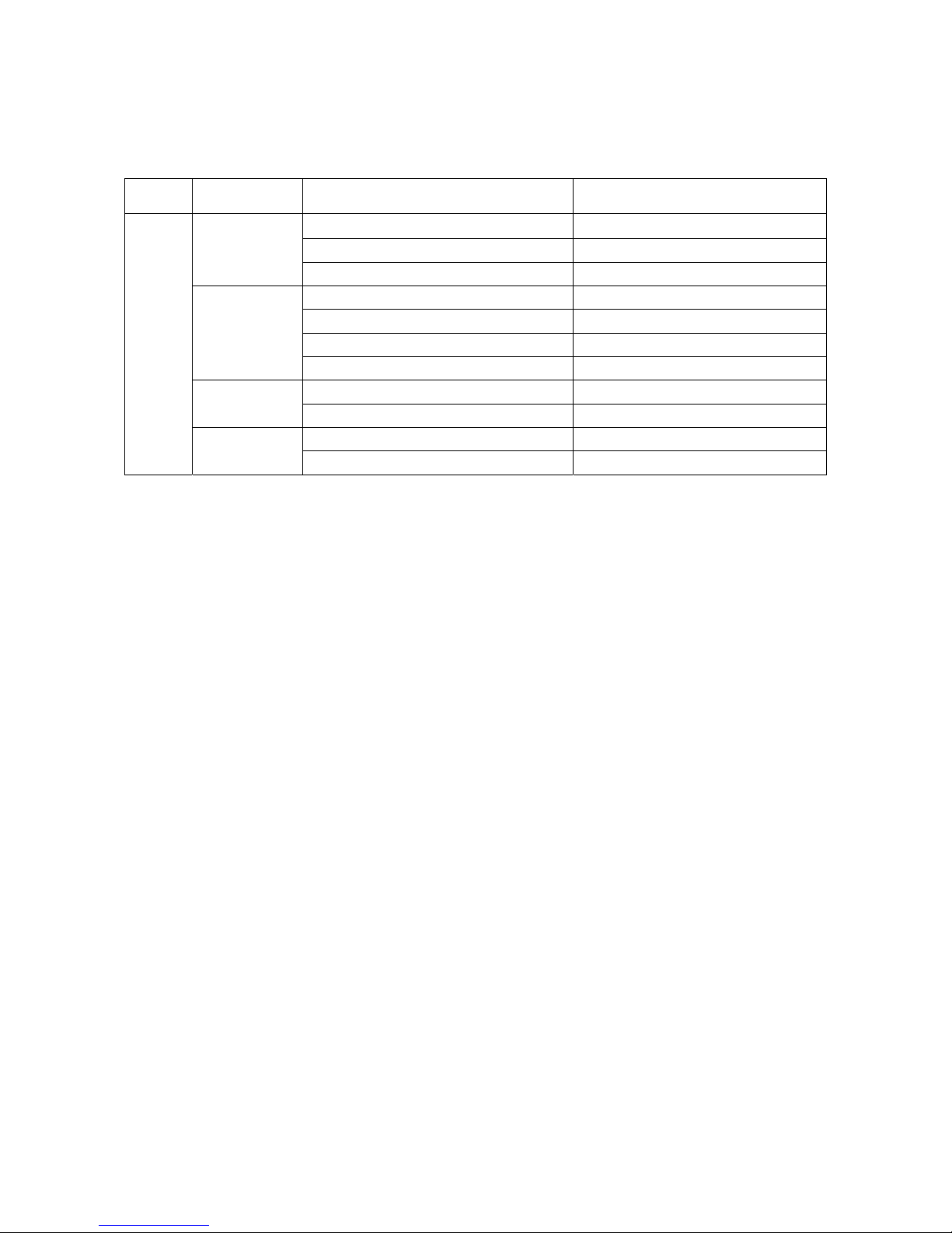
2.1 Model Names of Indoor/Outdoor units
Series Capacity Indoor units Outdoor units
WE009AMFI15CLD AN009AMFI15RPD
9k
Inverter
12k
18k
24k
WE009AMFI15HLD YN009AMFI15RPD
WE009GMFI15HLD YN009GMFI15RPD
WE012AMFI15CLD AN012AMFI15RPD
WE012AMFI15HLD YN012AMFI15RPD
WE012GMFI15CLD AN012GMFI15RPD
WE012GMFI15HLD YN012GMFI15RPD
WE018GMFI15CLD AN018GMFI15RPD
WE018GMFI15HLD YN018GMFI15RPD
WE024GMFI15CLD AN024GMFI15RPD
WE024GMFI15HLD YN024GMFI15RPD
4
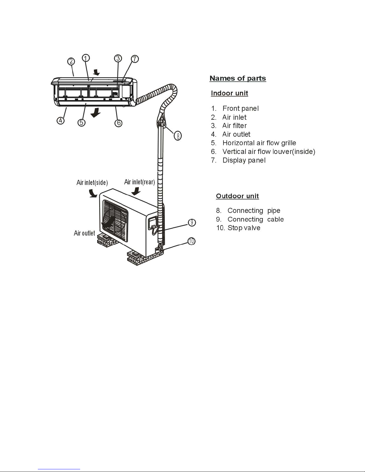
2.2 Part names of Indoor/Outdoor units
5
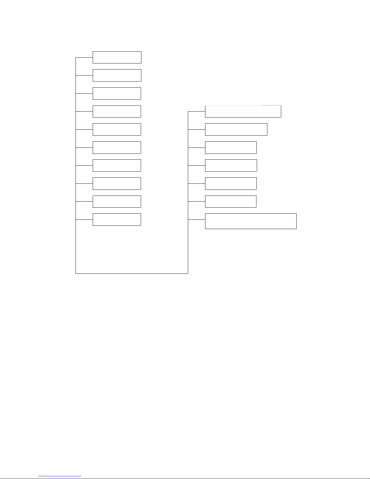
2.3 Functions of Indoor/Outdoor units
Filter
Cold Catalyst Filter
Ionizer(O)
Silver Ion Filter
Vitamin C Filter(O)
3M HAF Filter(O)
Bio Filter(O)
Golden Fin(O)
Self Clean(O)
Follow Me(O)
Refrigerant Leakage Detect
Heat Compensation(O)
O: optional function
Louver Position Memory Function
8 Degree Heating(O)
Self-diag. Function
PTC Heating Belt(O)
Compressor Crankcase Heater
(standard for MS11D-22HRDN1-MN10W)
6

Cold Catalyst Filter:
Eliminate formaldehyde and other volatile organic compounds as well as harmful gases and odors.
Ionizer:
Release negative ions, eliminate odor, dust, smoke and pollen particles to give you fresh and healthy air.
Silver Ion Filter:
Sterilize bacteria effectively by decomposing cell wall of bacteria.
Vitamin C Filter:
Release Vitamin C which can eliminate active oxygen to beautify the skin.
3M HAM Filter:
Open-hole-structure with charged electrostatic effectively capture dust and particles, ensure maximum air
flow and minimum pressure drop.
Bio Filter(O):
Bio filter consists of a specialized biological enzyme and Eco filter. The Eco filter catches very small airborne
dust particles and bacteria, fungi and microbes. Biological enzyme kills bacteria by dissolving their cell wall
thus eliminating the problem of re-pollution.
Golden Fin:
The Golden hydrophilic condenser can improve the heating efficiency by accelerating the defrosting process.
The unique anticorrosive golden coating on the condenser can withstand the salty air, rain and other corrosive
elements.
Self Clean:
When this function is activated, firstly the indoor unit operates as Fan-only mode with low fan speed, during
this period the condensed water will take some dust on evaporator fins away. After that the unit turns to
heating operation with low fan speed which dries the inside of indoor unit. Finally it turns to fan-only mode and
blows away the wet air. The whole process cleans the internal side of indoor unit and prevents the breeding of
bacteria.
Follow me:
With this technology, a temperature sensor is built in the remote control when you stay close to the remote
control, the unit will automatically change the operation mode to supply comfortable temperature just like the
air conditioner is following you.
Louver position memory function:
When starting the unit again after shutting down, its louver will restore to the angle originally set by the user
Refrigerant leakage detect:
The refrigerant leakage detect function can better prevent the compressor being damaged by refrigerant
leakage or compressor overload.
Self-diag.Function:
Monitoring some abnormal operations or parts failures, microcomputer of the air conditioner will switch off and
protect the system automatically.Meanwhile, the error or protection code will be displayed on the indoor unit.
PTC heating belt:
With a PTC heating belt fitted on the base plate of the outdoor unit, the rain, snow or defrosted water
accumulating on the base plate is avoided.
Compressor crankcase heater:
The oil dissolves easily in refrigerant, especially in low temperature condition. The crankcase heating belt can
heat the bottom of the compressor to avoid pumping out too much oil with the refrigerant, which helps to
protect the compressor.
7
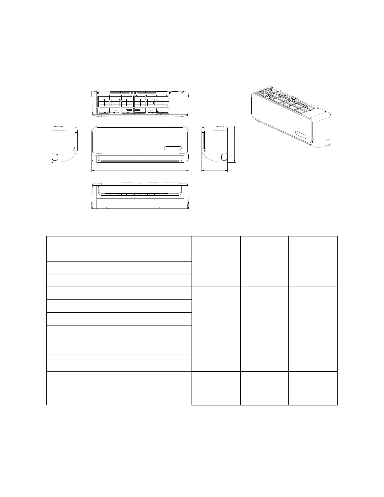
3. Dimension
3.1 Indoor Unit
H
W
D
Model W D H
WE009AMFI15CLD
WE009AMFI15HLD
WE009GMFI15HLD
WE012AMFI15CLD
WE012AMFI15HLD
WE012GMFI15CLD
WE012GMFI15HLD
WE018GMFI15CLD
WE018GMFI15HLD
680mm
(26.8in)
770mm
(30.3in)
905mm
(35.6in)
178mm
(7.0in)
188mm
(7.4in)
198mm
(7.8in)
255mm
(10.0in)
255mm
(10.0in)
275mm
(10.8in)
WE024GMFI15CLD
WE024GMFI15HLD
8
1030mm
(40.6in)
218mm
(8.6in)
315mm
(12.4in)
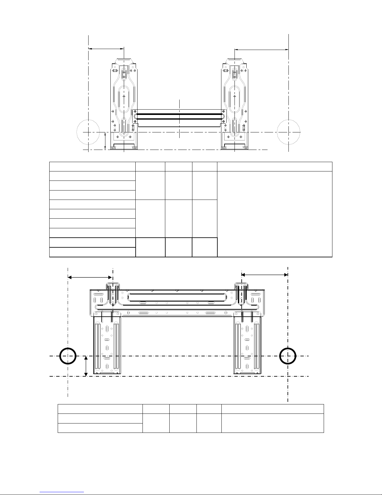
L
H
R
Model R L H Dimension of installation hole
WE009AMFI15CLD
WE009AMFI15HLD
WE009GMFI15HLD
WE012AMFI15CLD
WE012AMFI15HLD
WE012GMFI15CLD
WE012GMFI15HLD
WE018GMFI15CLD
WE018GMFI15HLD
92mm
(3.6in)
95mm
(3.7in)
80mm
(3.1in)
170mm
(6.7in)
170mm
(6.7in)
100mm
(3.9in)
45mm
(1.8in)
45mm
(1.8in)
45mm
(1.8in)
Φ65mm(2.56in)
L
H
Model R L H Dimension of installation hole
WE024GMFI15CLD
WE024GMFI15HLD
163mm
(6.4in)
293mm
(11.5in)
45mm
(1.8in)
R
Φ65mm(2.56in)
9
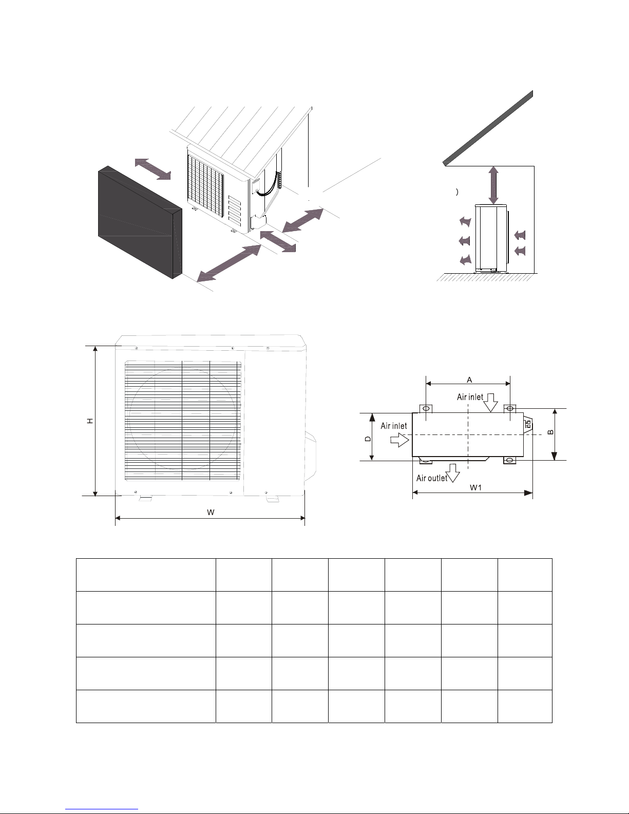
4.2 Outdoor Unit
More than 30cm(11.8in)
More than 60cm(23.6in)
More than 30cm(11.8in)
F
e
n
c
e
o
b
o
s
r
t
a
c
l
e
s
More than 60cm(23.6in)
More than 70cm(27.6in)
(Service space
︶
Note: The above drawing is only for reference. The appearance of your units may be different.
Model W H D W1 A B
YN009GMFI15RPD
AN009AMFI15RPD
YN009AMFI15RPD
YN012AMFI15RPD
700mm
(27.6in)
660mm
(26.0in)
660mm
(26.0in)
660mm
(26.0in)
240mm
(9.4in)
265mm
(10.4in)
265mm
(10.4in)
265mm
(10.4in)
10
540mm
(21.3in)
540mm
(21.3in)
540mm
(21.3in)
540mm
(21.3in)
757mm
(29.8in)
732mm
(28.8in)
732mm
(28.8in)
732mm
(28.8in)
458mm
(18.0in)
458mm
(18.0in)
458mm
(18.0in)
458mm
(18.0in)
250mm
(9.8in)
276mm
(10.9in)
276mm
(10.9in)
276mm
(10.9in)
AN012AMFI15RPD
660mm
(26.0in)
265mm
(10.4in)
540mm
(21.3in)
732mm
(28.8in)
458mm
(18.0in)
276mm
(10.9in)
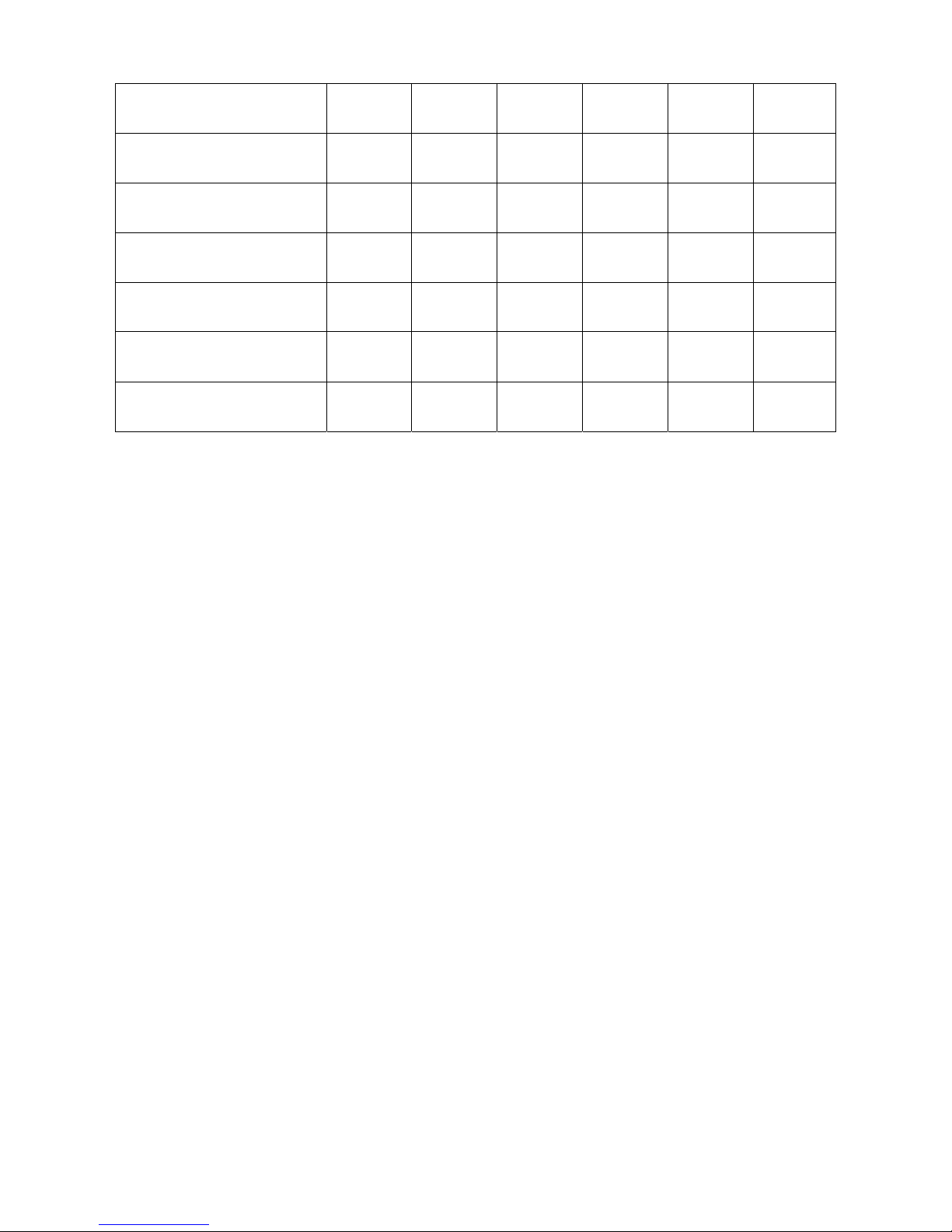
YN012GMFI15RPD
AN012GMFI15RPD
AN018GMFI15RPD
YN018GMFI15RPD
AN024GMFI15RPD
YN024GMFI15RPD
780mm
(30.7in)
780mm
(30.7in)
760mm
(29.9in)
760mm
(29.9in)
845mm
(33.3in)
845mm
(33.3in)
250mm
(9.8in)
250mm
(9.8in)
285mm
(11.2in)
285mm
(11.2in)
320mm
(12.6in)
320mm
(12.6in)
540mm
(21.3in)
540mm
(21.3in)
590mm
(23.2in)
590mm
(23.2in)
700mm
(27.6in)
700mm
(27.6in)
843mm
(33.2in)
843mm
(33.2in)
823mm
(32.4in)
823mm
(32.4in)
908mm
(35.7in)
908mm
(35.7in)
549mm
(21.6in)
549mm
(21.6in)
530mm
(20.9in)
530mm
(20.9in)
560mm
(22.0in)
560mm
(22.0in)
276mm
(10.9in)
276mm
(10.9in)
290mm
(11.4in)
290mm
(11.4in)
335mm
(13.2in)
335mm
(13.2in)
11
R
R
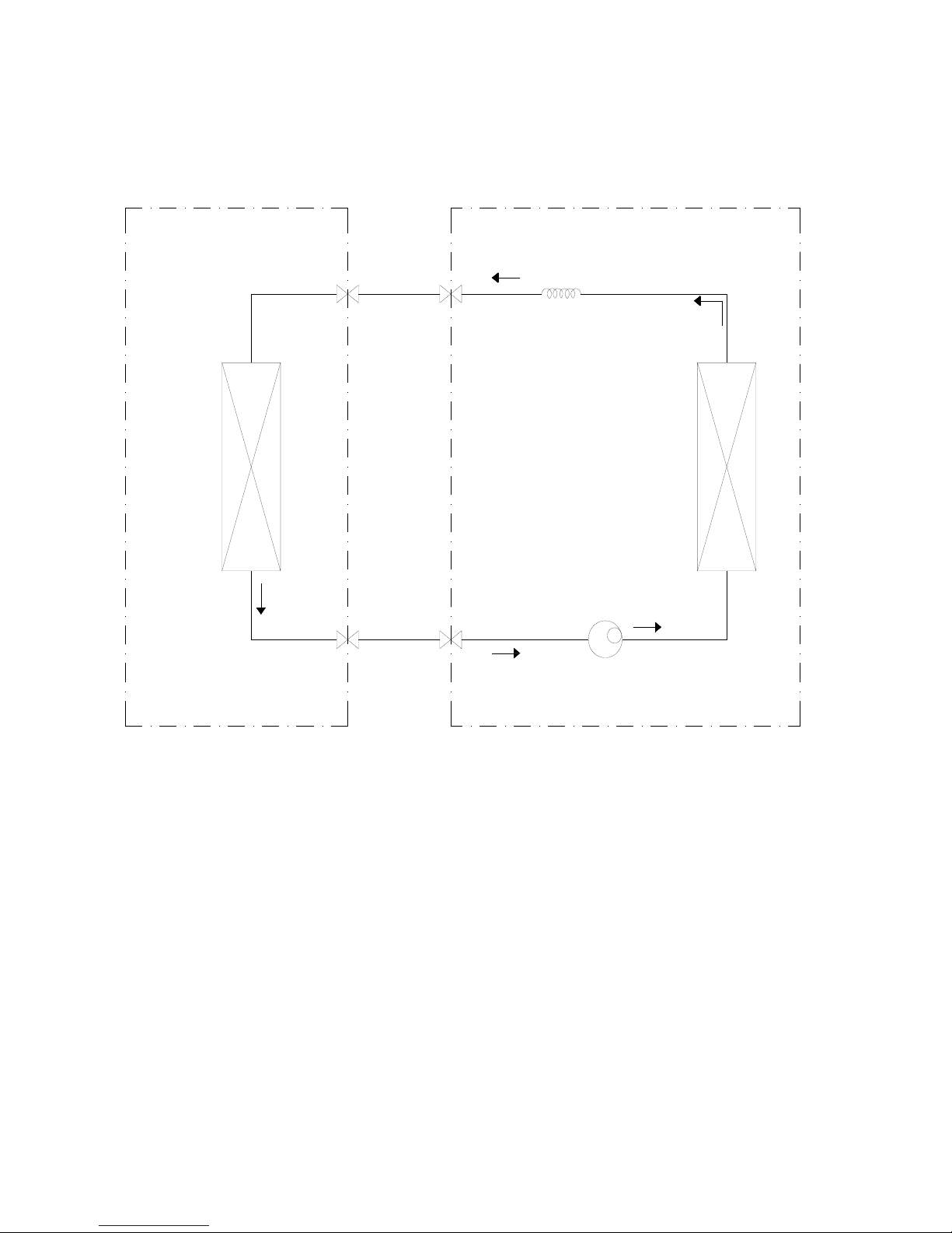
4. Refrigerant Cycle Diagram
For cooling only models:
INDOO
HEAT
EXCHANGE
(EVAPORATOR)
OUTDOO
LIQUID SIDE
CAPILIARY TUBE
HEAT
EXCHANGE
(CONDENSER)
GAS SIDE
COMPRESSOR
12
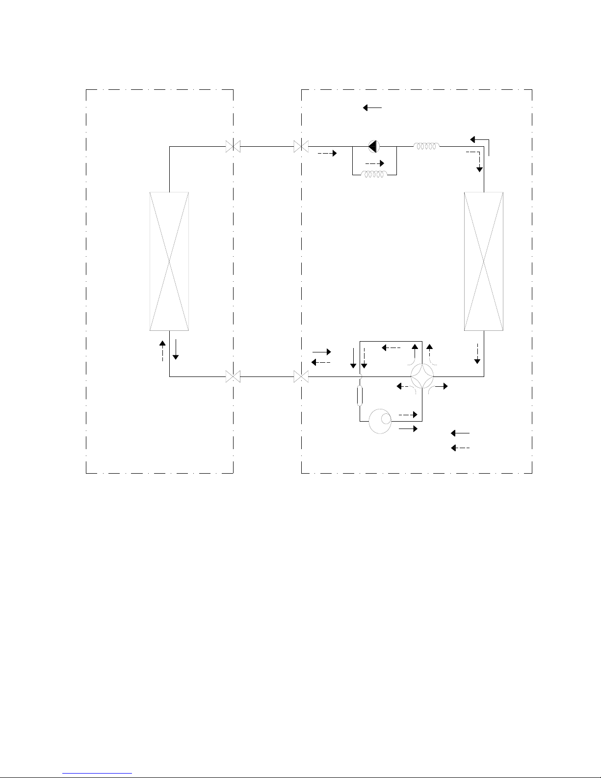
R
R
For heat pump models:
INDOO
OUTDOO
HEAT
EXCHANGE
(EVAPORATOR)
LIQUID SIDE
2-WAY VALVE
GAS SIDE
3-WAY VALVE
CHECK VALVE
(Heating Model only)
CAPILIARY TUBE
ACCUMULATOR
HEAT
EXCHANGE
(CONDENSER)
REVERSING VALVE
(Heating Model only)
COMPRESSOR
COOLING
HEATING
13
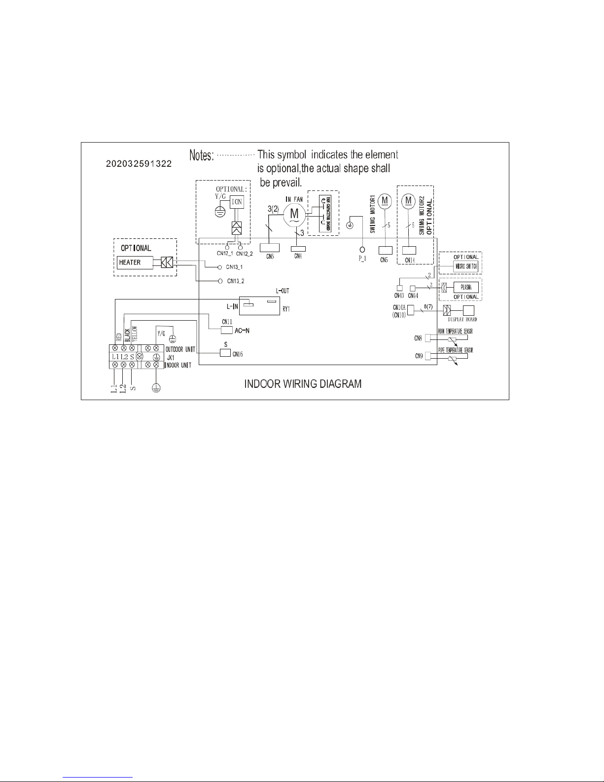
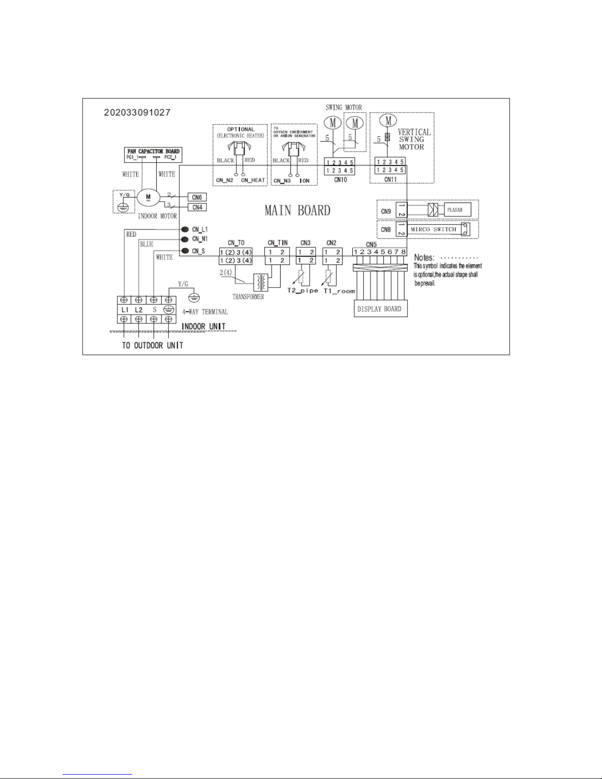
5. Wiring Diagram
5.1 Indoor Unit
9000 BTU, 230V, Heat Pump / 12000 BTU, 230V, Cool Only / 12000 BTU, 230V, Heat Pump
14
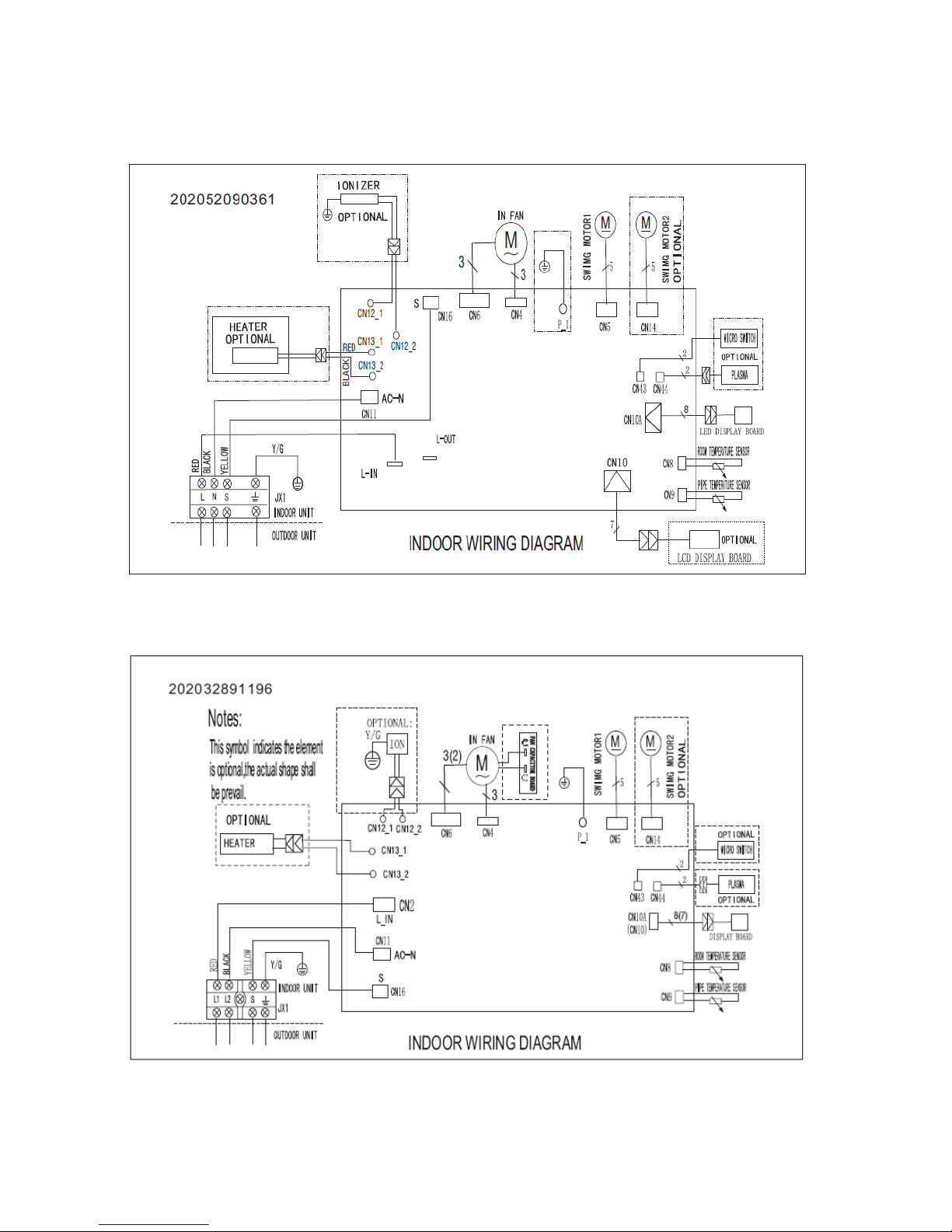
9000 BTU, 115V, Cool Only / 9000 BTU, 115V, Heat Pump
12000 BTU, 115V, Cool Only / 12000 BTU, 115V, Heat Pump
18000 BTU, 230V, Cool Only / 18000 BTU, 230V, Heat Pump
15
24000 BTU, 230V, Cool Only / 24000 BTU, 230V, Heat Pump
16
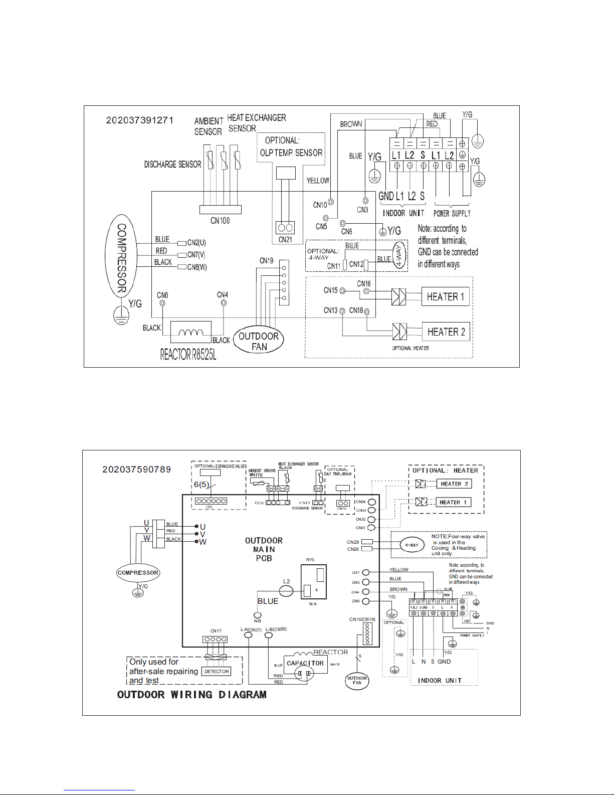
5.2 Outdoor Unit
9000 BTU, 230V, Heat Pump / 12000 BTU, 230V, Cool Only / 12000 BTU, 230V, Heat Pump
9000 BTU, 115V, Cool Only / 9000 BTU, 115V, Heat Pump
12000 BTU, 115V, Cool Only / 12000 BTU, 115V, Heat Pump
17
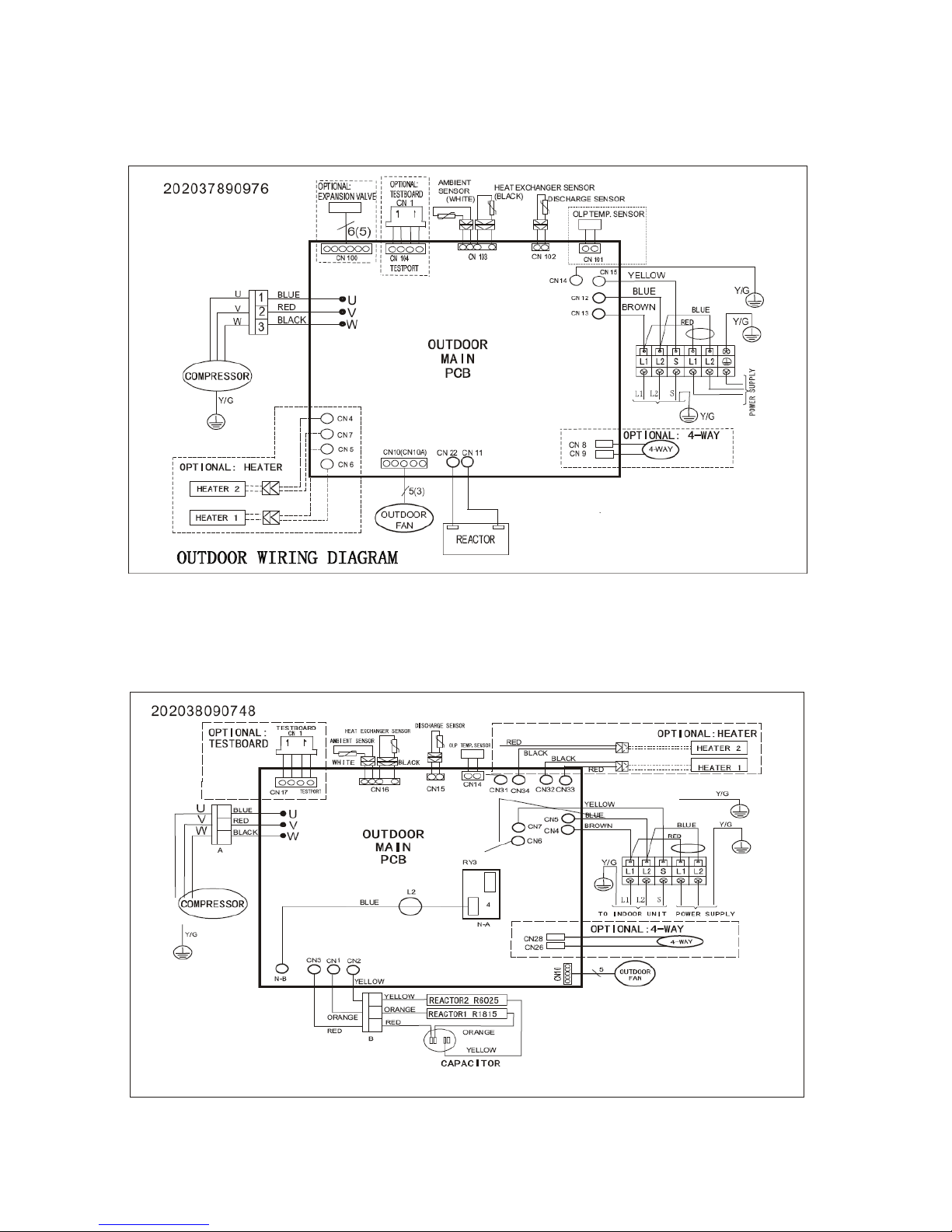
18000 BTU, 230V, Cool Only / 18000 BTU, 230V, Heat Pump
24000 BTU, 230V, Cool Only / 24000 BTU, 230V, Heat Pump
18
 Loading...