

Pioneer VSXD-607 Service manual
TV POWER
RECEIVER POWER
POWER
TV FUNC
MUTING
FQ
ENTER
FQ
–
VOL VOL
CHANNEL
MULTI CONTROL
DVD
LD/SAT CD
TV CONTROL
VCR
TUNER
PERSONAL
SURROUND
DSP MODE
ATT TEST TONE
CENTER
REAR
SUBWOOFER
EFFECT
DISC
CLASS TV/VCR
MODE CHECK FUNCTION
MULTI
COMMANDER
SYSTEM OFF
OPERATION
SET UP
MULTI CONTROL COMMANDER
PRE-PROGRAMMED AND LEARNING
AUDIO/VIDEO MULTI-CHANNEL RECEIVER
VSX-D607S
THIS MANUAL IS APPLICABLE TO THE FOLLOWING MODEL(S) AND TYPE(S).
Type
Model
VSX-D607S
Power Requirement
KUXJI AC120V
KCXJI AC120V
SDXJI AC110V/120-127V/220V/240V With the voltage selector
The voltage can be converted by the
following method.
ORDER NO.
RRV1897
CONTENTS
1. SAFETY INFORMATION ...................................... 2
2. EXPLODED VIEWS AND PARTS LIST................ 3
3. SCHEMATIC DIAGRAM ....................................... 8
4. PCB CONNECTION DIAGRAM.......................... 32
5. PCB PARTS LIST ............................................... 44
6. ADJUSTMENT .................................................... 51
PIONEER ELECTRONIC CORPORATION 4-1, Meguro 1-Chome, Meguro-ku, Tokyo 153-8654, Japan
PIONEER ELECTRONICS SERVICE, INC. P.O. Box 1760, Long Beach, CA 90801-1760, U.S.A.
PIONEER ELECTRONIC (EUROPE) N.V. Haven 1087, Keetberglaan 1, 9120 Melsele, Belgium
PIONEER ELECTRONICS ASIACENTRE PTE. LTD. 501 Orchard Road, #10-00 Lane Crawford Place, Singapore 0923
c
PIONEER ELECTRONIC CORPORATION 1998
7. GENERAL INFORMATION ................................ 53
7.1 DISPLAY....................................................... 53
7.2 PCB LOCATION ........................................... 55
7.3 BLOCK DIAGRAM........................................ 56
7.4 REMOTE CONTROL UNIT .......................... 58
[CU-VSX128 (AXD7153)]
8. PANEL FACILITIES AND SPECIFICATIONS.... 62
T - IZK JAN. 1998 Printed in Japan

VSX-D607S
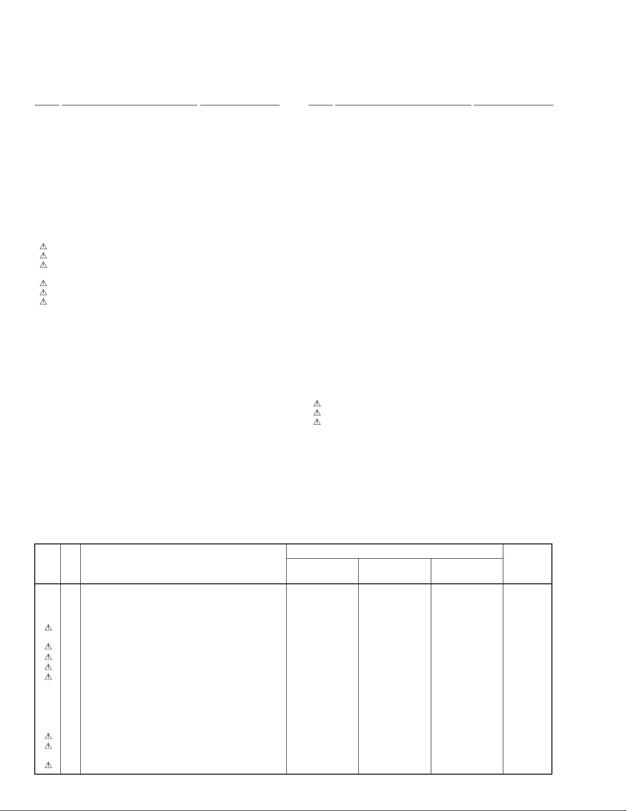
1. SAFETY INFORMATION
This service manual is intended for qualified service technicians ; it is not meant for the casual do-ityourselfer. Qualified technicians have the necessary test equipment and tools, and have been trained
to properly and safely repair complex products such as those covered by this manual.
Improperly performed repairs can adversely affect the safety and reliability of the product and may
void the warranty. If you are not qualified to perform the repair of this product properly and safely, you
should not risk trying to do so and refer the repair to a qualified service technician.
WARNING
Lead in solder used in this product is listed by the California Health and Welfare agency as a known reproductive toxicant which may
cause birth defects or other reproductive harm (California Health & Safety Code, Section 25249.5).
When servicing or handling circuit boards and other components which contain lead in solder, avoid unprotected skin contact with
the solder. Also, when soldering do not inhale any smoke or fumes produced.
NOTICE
(FOR CANADIAN MODEL ONLY)
Fuse symbols (fast operating fuse) and/or (slow operating fuse) on PCB indicate that replacement parts must
be of identical designation.
REMARQUE
(POUR MODÈLE CANADIEN SEULEMENT)
Les symboles de fusible (fusible de type rapide) et/ou (fusible de type lent) sur CCI indiquent que les pièces
de remplacement doivent avoir la même désignation.
(FOR USA MODEL ONLY)
1. SAFETY PRECAUTIONS
The following check should be performed for the
continued protection of the customer and service
technician.
LEAKAGE CURRENT CHECK
Measure leakage current to a known earth ground (water
pipe, conduit, etc.) by connecting a leakage current tester
such as Simpson Model 229-2 or equivalent between the
earth ground and all exposed metal parts of the appliance
(input/output terminals, screwheads, metal overlays, control
shaft, etc.). Plug the AC line cord of the appliance directly
into a 120V AC 60Hz outlet and turn the AC power switch
on. Any current measured must not exceed 0.5mA.
Reading should
not be above
0.5mA
Earth
ground
Device
under
test
Also test with
plug reversed
(Using AC adapter
plug as required)
Leakage
current
tester
Test all
exposed metal
surfaces
ANY MEASUREMENTS NOT WITHIN THE LIMITS
OUTLINED ABOVE ARE INDICATIVE OF A POTENTIAL
SHOCK HAZARD AND MUST BE CORRECTED BEFORE
RETURNING THE APPLIANCE TO THE CUSTOMER.
2. PRODUCT SAFETY NOTICE
Many electrical and mechanical parts in the appliance
have special safety related characteristics. These are
often not evident from visual inspection nor the protection
afforded by them necessarily can be obtained by using
replacement components rated for voltage, wattage, etc.
Replacement parts which have these special safety
characteristics are identified in this Service Manual.
Electrical components having such features are identified
by marking with a
in this Service Manual.
The use of a substitute replacement component which does
not have the same safety characteristics as the PIONEER
recommended replacement one, shown in the parts list in
this Service Manual, may create shock, fire, or other hazards.
Product Safety is continuously under review and new
instructions are issued from time to time. For the latest
information, always consult the current PIONEER Service
Manual. A subscription to, or additional copies of, PIONEER
Service Manual may be obtained at a nominal charge from
PIONEER.
on the schematics and on the parts list
AC Leakage Test
2
VSX-D607S
2. EXPLODED VIEWS AND PARTS LIST
NOTES:• Parts marked by "NSP" are generally unavailable because they are not in our Master Spare Parts List.
The mark found on some component parts indicates the importance of the safety factor of the part.
•
Therefore, when replacing, be sure to use parts of identical designation.
Screws adjacent to mark on the product are used for disassembly.
•
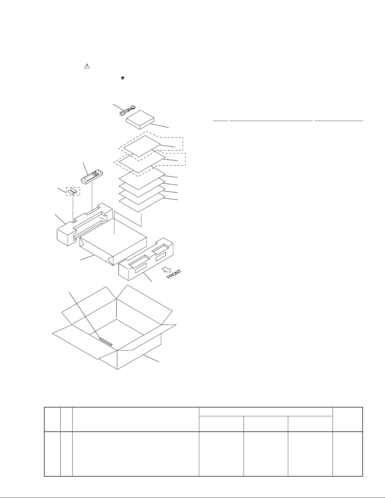
2.1 PACKING
2
Refer to
"7.4 REMOTE CONTROL UNIT".
1
11
9
13
6
SDXJI Type Only
15
8
KCXJI Type Only
5
7
4
3
(1) PACKING PARTS LIST
Mark No. Description Part No.
NSP 1 Dry Cell Battery (LR6,AA) AEX1007
2 FM Antenna ADH7004
3 Operating Instructions See Contrast table (2)
4 Sub Instruction Manual ARH7015
(Remote Control Unit)(English)
NSP 5 Warranty Card See Contrast table (2)
6 AM Loop Antenna ATB7009
7 Sub Instruction Manual ARH7030
(AC-3) (English)
8 Operating Instructions See Contrast table (2)
(French)
9 Remote Control Unit AXD7153
(CU-VSX128)
10 Front Pad AHA7137
11 Rear Pad AHA7140
12 Packing Case See Contrast table (2)
13 Packing Sheet AHG7010
14 Sub Pad B AHB7027
15 Caution 220V Label See Contrast table (2)
14
10
12
(2) CONTRAST TABLE
VSX-D607S/KUXJI, KCXJI and SDXJI are constructed the same except for the following :
.oNtraP
kraM.oNnoitpircseDdnalobmyS
3
3
PSN
5
8
21
)hsilgnE(snoitcurtsnIgnitarepO
)hsinapS/esenihC/hsilgnE(snoitcurtsnIgnitarepO
draCytnarraW
)hcnerF(snoitcurtsnIgnitarepO
esaCgnikcaP
S706D-XSV
IJXUK/
0417BRA
desutoN
1501YRA
desutoN
0757DHA
S706D-XSV
IJXCK/
0417BRA
desutoN
5701YRA
9817CRA
0757DHA
S706D-XSV
skrameR
IJXDS/
desutoN
5517ERA
7701YRA
desutoN
1757DHA
51
lebaLV022noituaC
desutoN
desutoN
3001RRA
3
VSX-D607S
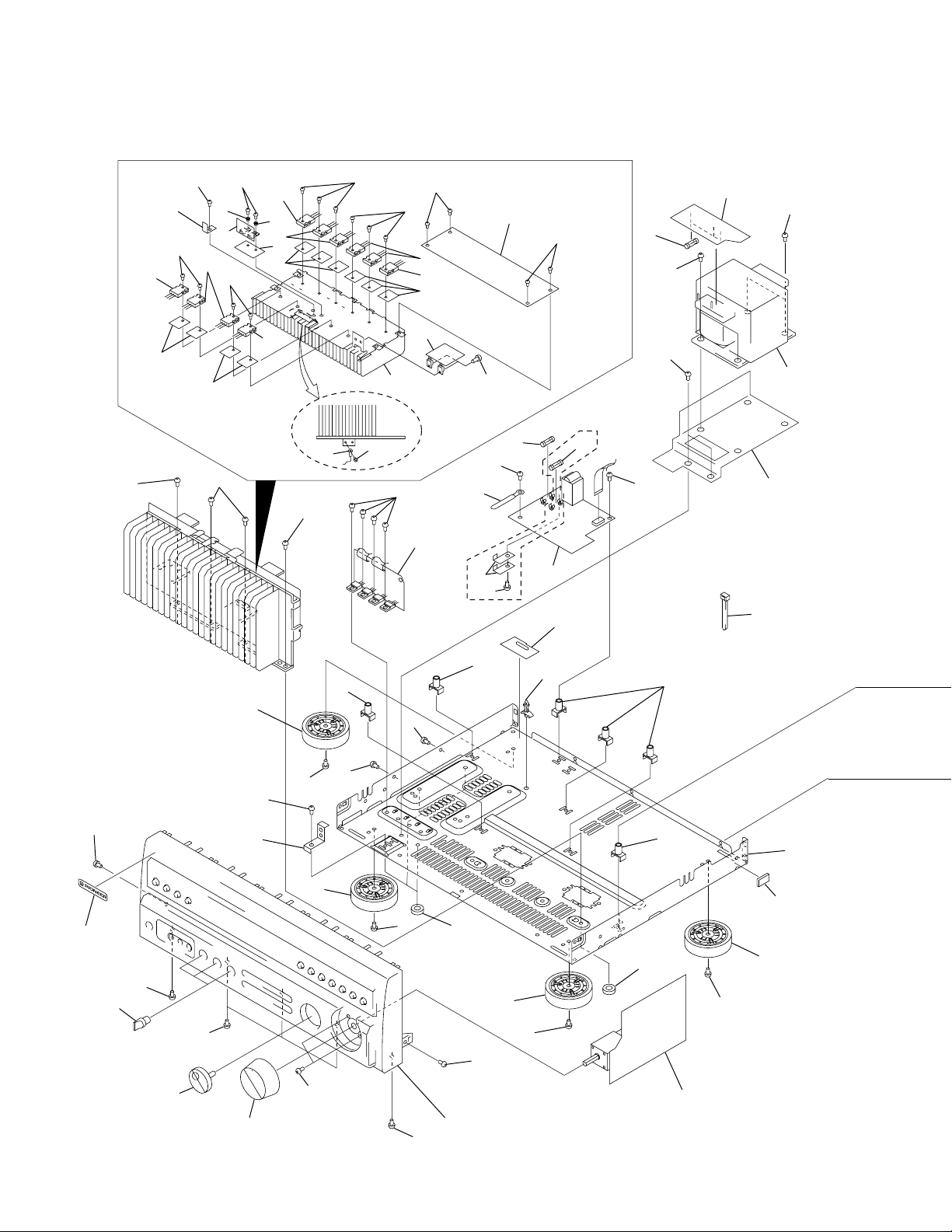
2.2 EXTERIOR
48
14
33
19
45
50
13
33
48
27
2
45
50
14
14
13
33
27
32
48
43
45
50
25
50
45
4
11
14
13
33
50
36
57
58
50
51
3
5
16
56
50
51
17
50
SDXJI Type
Only
64
7
59
56
15
41
53
42
55
39
50
40
50
38
20
46
50
50
50
21
34
50
50
34
50
60
21
50
55
Refer to
"2.3 FRONT PANEL SECTION".
50
30
60
34
34
22
61
20
50
9
4

51
VSX-D607S
50
24
50
31
51
1
51
29
29
63
10
44
26
51
23
31
35
50
28
SDXJI Type
Only
50
50
37
50
50
1862
54
50
50
50
50
12
6
8
5
VSX-D607S
(1) EXTERIOR PARTS LIST
Mark No. Description Part No. Mark No. Description Part No.
NSP 2 MOS FET Assy AWZ8497
1 INPUT Assy See Contrast table (2)
3 TRANS Assy AWZ8496
4 REG.1 Assy AWZ8507
5 R/C AMP Assy AWZ8504
6 FM/AM TUNER Module See Contrast table (2)
NSP 7 PRIMARY Assy See Contrast table (2)
8 VIDEO/SR Assy AWZ8509
9 VOLUME Assy AWZ8047
10 R/C SPEAKER Assy See Contrast table (2)
11 REG.2 Assy AWZ8498
12 DOLBY DIGITAL Assy AWX7042
13 Transistor(Q3,Q4,Q7,Q8,Q10) 2SA1962
14 Transistor(Q1,Q2,Q5,Q6,Q9) 2SC5242
15 Power Transformer See Contrast table (2)
16 Fuse (FU3-FU5 : 1.6A) REK1077
17 Fuse (FU1) See Contrast table (2)
18 AC Power Cord See Contrast table (2)
19 FET Plate ANG7124
20 Insulator AMR7198
21 Insulator PNW2766
22 Chassis ANA7052
23 Rear Panel See Contrast table (2)
24 Bonnet Case ANE7136
25 Radiator ANH7050
26 Shield Case ANK7037
NSP 27 Bushing AEC1402
NSP 28 Cushion AEB7076
29 PCB Support AEC1581
30 PCB Support AEC7006
NSP 36 Clamper RNE1277
37 Washer AEC7110
38 Round Knob L AAB7082
39 Round Knob S AAB7106
40 Jog Knob AAB7048
41 Trans Frame ANG7140
42 Name Plate PAM1755
NSP 43 Cord with Plug (J105) DE012CD0
44 Cushion Rubber AEB7081
45 Screw ABA1037
46 PCB Stopper ANG7136
47 .• • • • •
48 Screw ABA7019
49 • • • • •
50 Screw BBZ30P080FZK
51 Screw BBZ30P180FMC
52 • • • • •
NSP 53 Binder ZCA-BK1
54 Screw ABA7035
55 Screw ABA-298
56 Screw ABA1147
57 Barrier See Contrast table (2)
58 Push Rivet See Contrast table (2)
59 Spacer AEE7024
NSP 60 Spacer AEB7092
NSP 61 Spacer B AEB7086
62 Voltage Selector (S1) See Contrast table (2)
63 Voltage Selector (S2) See Contrast table (2)
64 Fuse (FU2 : 3.15A) See Contrast table (2)
31 PCB Support AEC7056
32 Sheet AEE1028
33 Sheet AEE7010
34 PCB Mold AMR2533
35 Cord Stopper See Contrast table (2)
(2) CONTRAST TABLE
VSX-D607S/KUXJI, KCXJI and SDXJI are constructed the same except for the following :
.oNtraP
kraM.oNnoitpircseDdnalobmyS
1
6
PSN
7
01
51
51
71
71
81
32
53
75
85
26
36
lenaPraeR
reirraB
teviRhsuP
yssATUPNI
eludoMRENUTMA/MF
yssAYRAMIRP
yssAREKAEPSC/R
)V021CA(remrofsnartrewoP
)V042/V022/V721-021/V011CA(remrofsnartrewoP
)A3.6:1UF(esuF
)A51.3:1UF(esuF
droCrewoPCA
reppotSdroC
)1S(rotceleSegatloV
)2S(rotceleSegatloV
S706D-XSV
IJXUK/
8417XWA
9127QXA
5688ZWA
5058ZWA
1617STA
desutoN
5801KER
desutoN
5101GDP
0567CNA
C22-MC
desutoN
desutoN
desutoN
desutoN
S706D-XSV
IJXCK/
8417XWA
9127QXA
5688ZWA
5058ZWA
1617STA
desutoN
5801KER
desutoN
5101GDP
0567CNA
C22-MC
desutoN
desutoN
desutoN
desutoN
S706D-XSV
skrameR
IJXDS/
9417XWA
2113QXA
6688ZWA
3168ZWA
desutoN
3617STA
desutoN
4601KER
7511GDA
2567CNA
B22-MC
7317CEA
8317CEA
705-XKA
4001XKA
46
)A51.3:2UF(esuF
desutoN
desutoN
4601KER
6

2.3 FRONT PANEL SECTION
VSX-D607S
15
12
3
9
5
7
6
15
1
15
15
11
2
15
13
15 15
14
4
14
15
15
15
15
15
8
16
FRONT PANEL SECTION PARTS LIST
•
10
Mark No. Description Part No. Mark No. Description Part No.
NSP 1 POWER SWITCH Assy AWZ8501
NSP 2 FRONT INPUT Assy AWZ8502
3 FL/U-COM Assy AWZ8043
NSP 4 Housing 5P Shield (J27) ADX1653
5 Power Button AAD7325
6 Tuner Button AAD7326
7 Input Button AAD7327
8 Func. Button AAD7328
9 SFC Button AAD7329
10 FL Panel AAK7295
11 FL Filter AAK7294
12 Sub Panel AAP7042
13 Front Panel AMB7501
14 Screw ABA7009
15 Screw BPZ30P080FMC
16 Screw BBZ30P080FZK
7
1
23
4
VSX-D607S
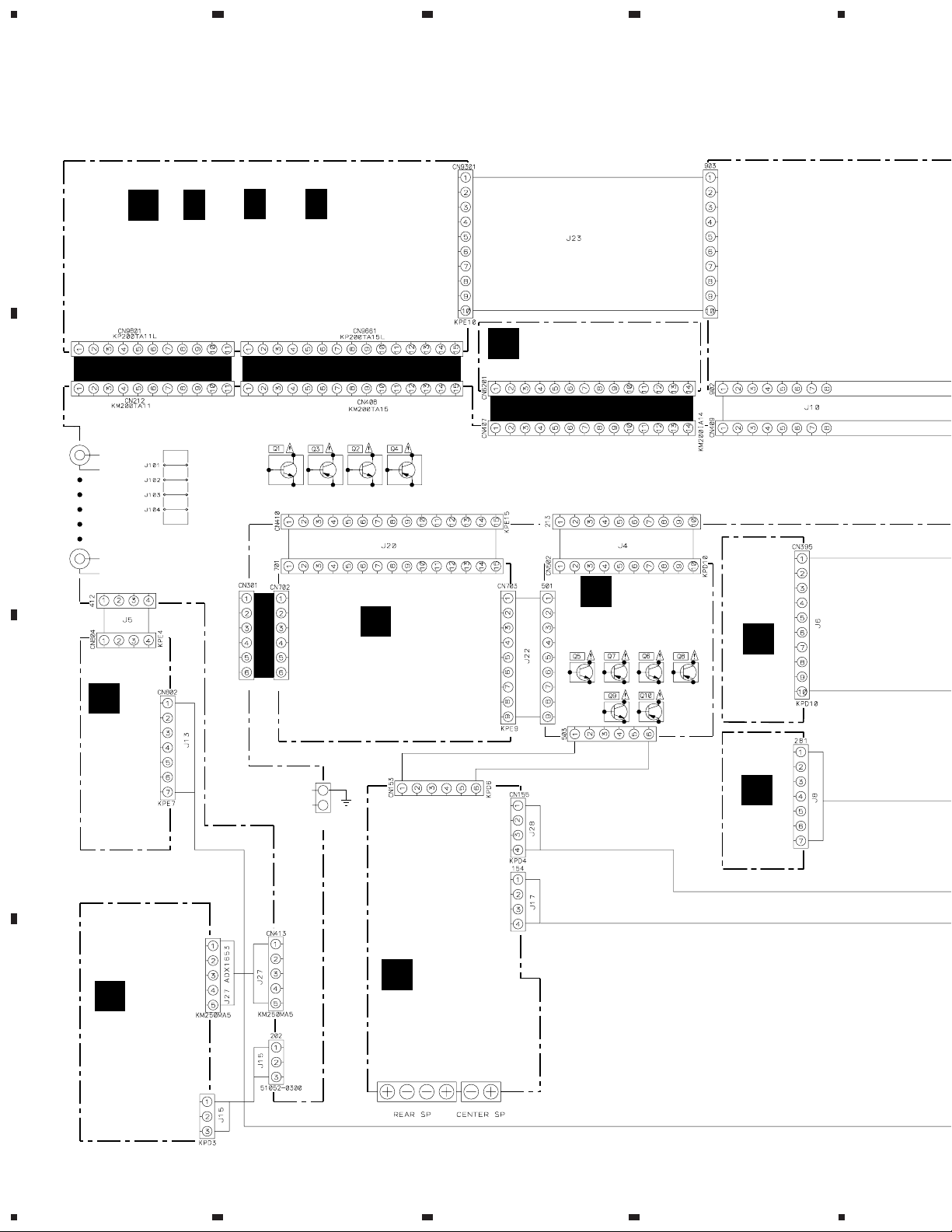
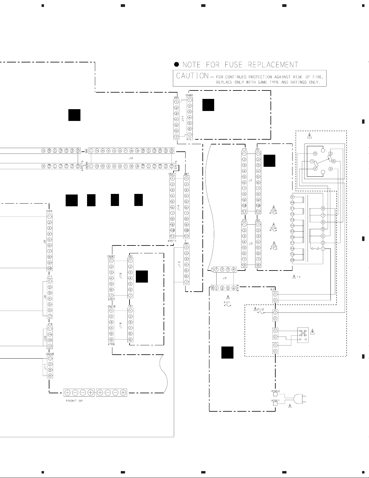
3. SCHEMATIC DIAGRAM
3.1 OVERALL CONNECTION DIAGRAM
Note : When ordering service parts, be sure to refer to "EXPLODED VIEWS and P AR TS LIST" or "PCB PARTS LIST".
A
()
1/3,
H
B
H
DOLBY DIGITAL ASSY
(AWX7042)
H
2/3,
H
3/3
FM/AM TUNER MODULE
O
(AXQ7219:KUXJI,KCXJI)
(AXQ3112:SDXJI)
K
I
VOLUME ASSY
(AWZ8047)
KM200TA6
KP200TA6L
L
VIDEO/SR
ASSY
C
(AWZ8509)
J165
DE012CD0
J16
R/C AMP ASSY
(AWZ8504)
J16
E
MOS FET
ASSY
(AWZ8497)
N
AKC-082
REG.2
ASSY
(AWZ8498)
F
FRONT INPUT
ASSY
D
8
(AWZ8502)
1234
CN1993
CN1992
J
R/C SPEAKER ASSY
(AWZ8505:KUXJI,KCXJI)
(AWZ8613:SDXJI)
5
A
FL/U-COM ASSY
(AWZ8043)
678
VSX-D607S
A
B
POWER SWITCH ASSY
(AWZ8501)
D
TRANS
ASSY
(AWZ8496)
SDXJI ONLY
S1
VOLTAGE
SELECTOR
240V
220V
120–
127V
110V
B
()
1/3,
C
C
INPUT ASSY
(AWX7148:KUXJI,KCXJI)
(AWX7149:SDXJI)
C
2/3,
C
3/3
INPUT
ASSY
FL/U-COM ASSY
REK1077
1.6A 125V
REK1077
1.6A 125V
REK1077
1.6A 125V
G
REG.1
ASSY
(AWZ8507)
REK1085
6.3A 125V
(KUXJI,KCXJI)
REK1064
3.15A 250V
(SDXJI)
REK1064
3.15A 250V
56
57
55
M
PRIMARY ASSY
INPUT ASSY
(AWZ8865:KUXJI,KCXJI)
(AWZ8866:SDXJI)
LIVE
NEUTRAL
POWER
TRANSFORMER
ATS7161 (KUXJI,KCXJI)
ATS7163 (SDXJI)
VOLTAGE
SELECTOR
AC POWER CORD
KUXJI and KCXJI :
PDG1015
AC120V 60Hz
SDXJI : ADG1157
AC110V/120-127V/220V/240V
50/60HZ
C
S2
D
9
5
6
7
8
1
VSX-D607S
23
4
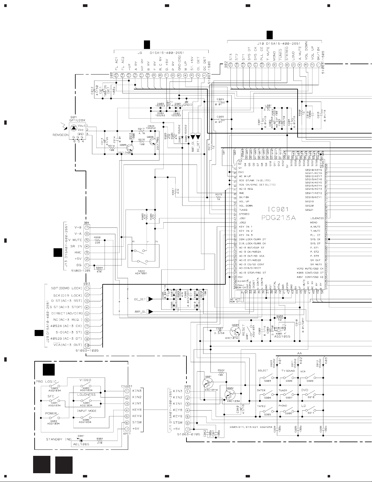
3.2 FL/U-COM AND PO WER SWITCH ASSEMBLIES
CN206
C
2/3
A
B
C
1/3
CN409
CN802
L
C
CN9301
2/3
H
POWER SWITCH ASSY
B
D
(AWZ8501)
10
POWER SWITCH ASSY
S981 : DSP MODE
S982 : POWER
S983 : DOLBY PRO LOGIC
S984 : LOUDNESS
S985 : VIDEO
S986 : INPUT MODE
A
B
1234
5
678
VSX-D607S
FL/U-COM ASSY
A
(AWZ8043)
: AUDIO SIGNAL ROUTE
A
B
CN411
1/3
TREBLEBASS
BALANCE
FL/U-COM ASSY
S901 : RESET
S903 : SELECT
S904 : ENTER
S905 : TAPE2
S906 : CD
S907 : TUNER
S908 : PHONO
S909 : VCR/TAPE1
S910 : DVD/TV
S911 : LD/SAT
S913 : CLASS
S914 : FM/AM
S915 : MEMORY
S916 : MPX
S918 : DIRECT
S919 : RETURN
S920 : SPEAKERS B
S921 : SPEAKERS A
S922 : MULTI JOG
VR1901 : BASS ( / )
VR1902 : TREBLE ( / )
VR1903 : BALANCE (L/R)
C
C
D
A
5
6
7
8
11

1
VSX-D607S
3.3 INPUT ASSY (1/3)
23
4
L
CN804
A
ADG [J19 (CN207) 5 pin]
(REC)
B
(P)
F
CN1993
(F-IN)
(T)
VCR OUT
(P)
(T)
(F-IN)
(REC)
O
CN6201
(T)
FUNCTION SW
C
INPUT ASSY
1/3
C
(AWX7148:KUXJI,KCXJI)
(AWX7149:SDXJI)
D
A
J10
12
C
1/3
1234

5
678
VSX-D607S
: AUDIO SIGNAL ROUTE
: AUDIO SIGNAL ROUTE (REAR)
(SL)
: AUDIO SIGNAL ROUTE (CENTER)
A
J14
(C)
: AUDIO SIGNAL ROUTE (TUNER)
(T)
: AUDIO SIGNAL ROUTE (PHONO)
(P)
: AUDIO SIGNAL ROUTE (REC)
(REC)
: AUDIO SIGNAL ROUTE (F.IN)
(F-IN)
(SL)
(C)
A
CN9661
3/3
H
B
(SL)
(C)
(SL)
(SL)
(SL)
C
(C)
3/3
(C)
(C)
(C)
I
J20
C
D
C
1/3
5
6
7
8
13
1
23
VSX-D607S
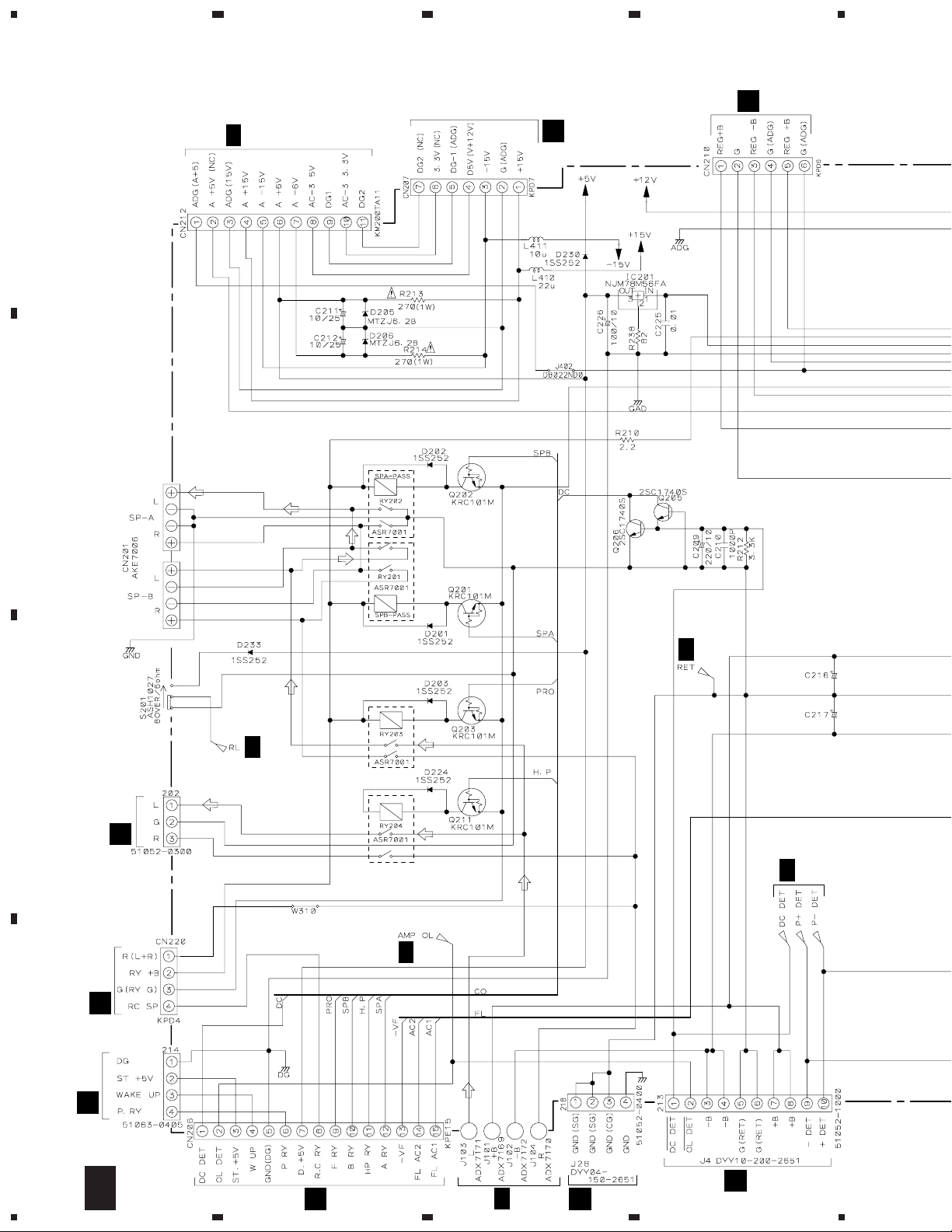
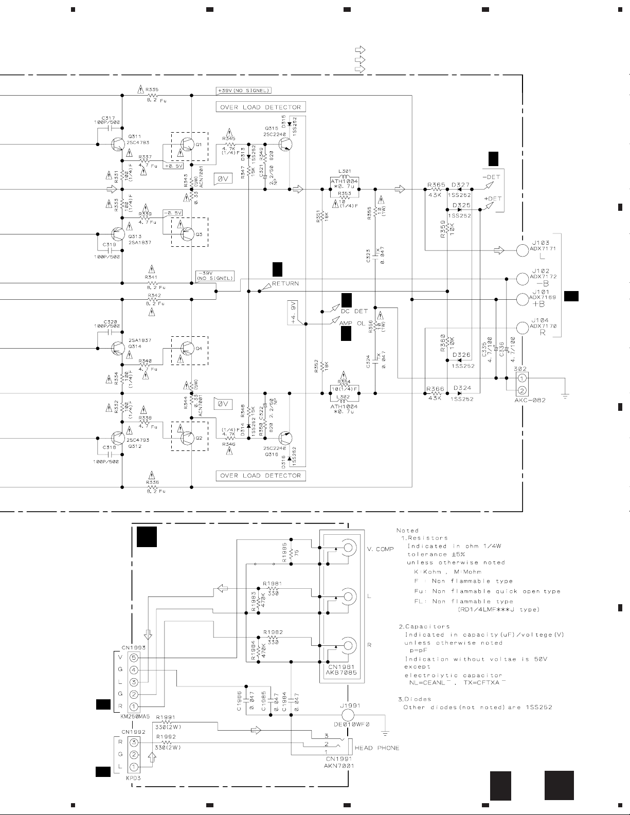
3.4 INPUT (2/3), TRANS AND MOS FET ASSEMBLIES
CN9801
H
1/3
A
B
G
J19
4
G
J18
C216,C217
KUXJI,KCXJI:
ACH7018(8200/71)
SDXJI:
C
3/3
C
2/3
C
(H.P)
CN1992
F
J17
J15
C
(H.P)
3/3
ACH7019(8200/80)
C
3/3
J
D
CN51
J3
M
K
14
C
2/3
1234
A
J9
C
3/3
J
CN155
CN502
N
J8
5
J8
C
INPUT ASSY
2/3
(AWX7148:
KUXJI,KCXJI)
(AWX7149:
SDXJI)
678
VSX-D607S
: AUDIO SIGNAL ROUTE
(H.P)
: AUDIO SIGNAL ROUTE (HEADPHONE)
TRANS ASSY
D
(AWZ8496)
A
B
C
3/3
C
2/3
C
2/3
C
2/3
C
2/3
FET DRIVER
C
TO POWER TRANS FORMER
C
2/3
OUTPUT PEAK DETECTOR
5
C
2/3
E
MOS FET ASSY
(AWZ8497)
C
2/3
6
7
D
E
8
15
D

1
23
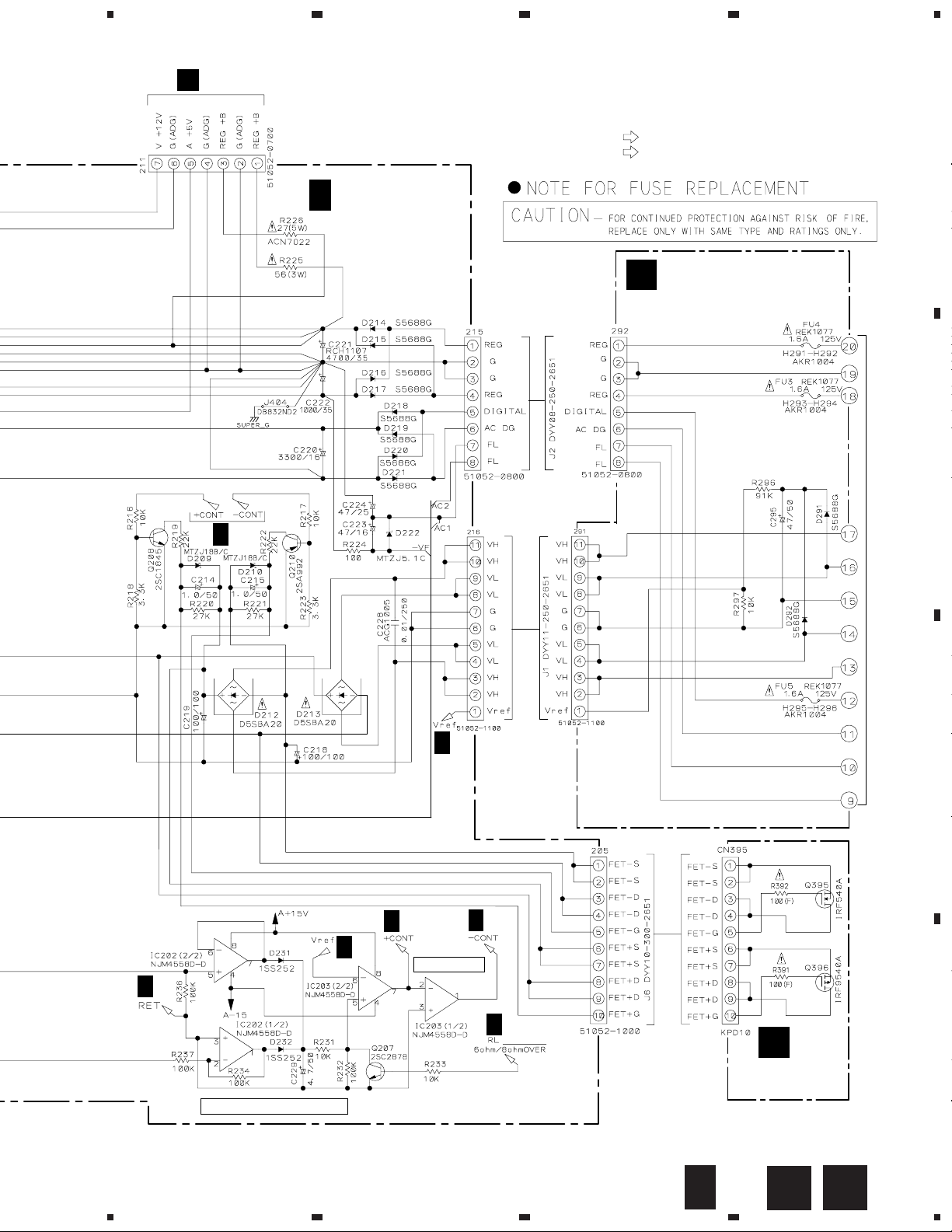
VSX-D607S
3.5 INPUT (3/3), FRONT INPUT AND REG.1 ASSEMBLIES
INPUT ASSY
3/3
A
C
(AWX7148:KUXJI,KCXJI)
(AWX7149:SDXJI)
4
B
C
CN702
I
C
1/3
REG.1 ASSY
G
(AWZ8507)
CN207
2/3
D
16
C
3/3
1234
G
C
CN210
2/3
C
5
678
VSX-D607S
: AUDIO SIGNAL ROUTE
(H.P)
: AUDIO SIGNAL ROUTE (HEADPHONE)
(F-IN)
: AUDIO SIGNAL ROUTE (F.IN)
A
2SC5242
C
2/3
2SA1962
C
2/3
2/3
C
2/3
C
B
2SA1962
2SC5242
F
FRONT INPUT ASSY
(AWZ8502)
(F-IN)
(F-IN)
C
2/3
C
CN413
1/3
C
J15
2/3
C
D
(H.P)
(H.P)
C
5
6
7
3/3
F
8
17
1
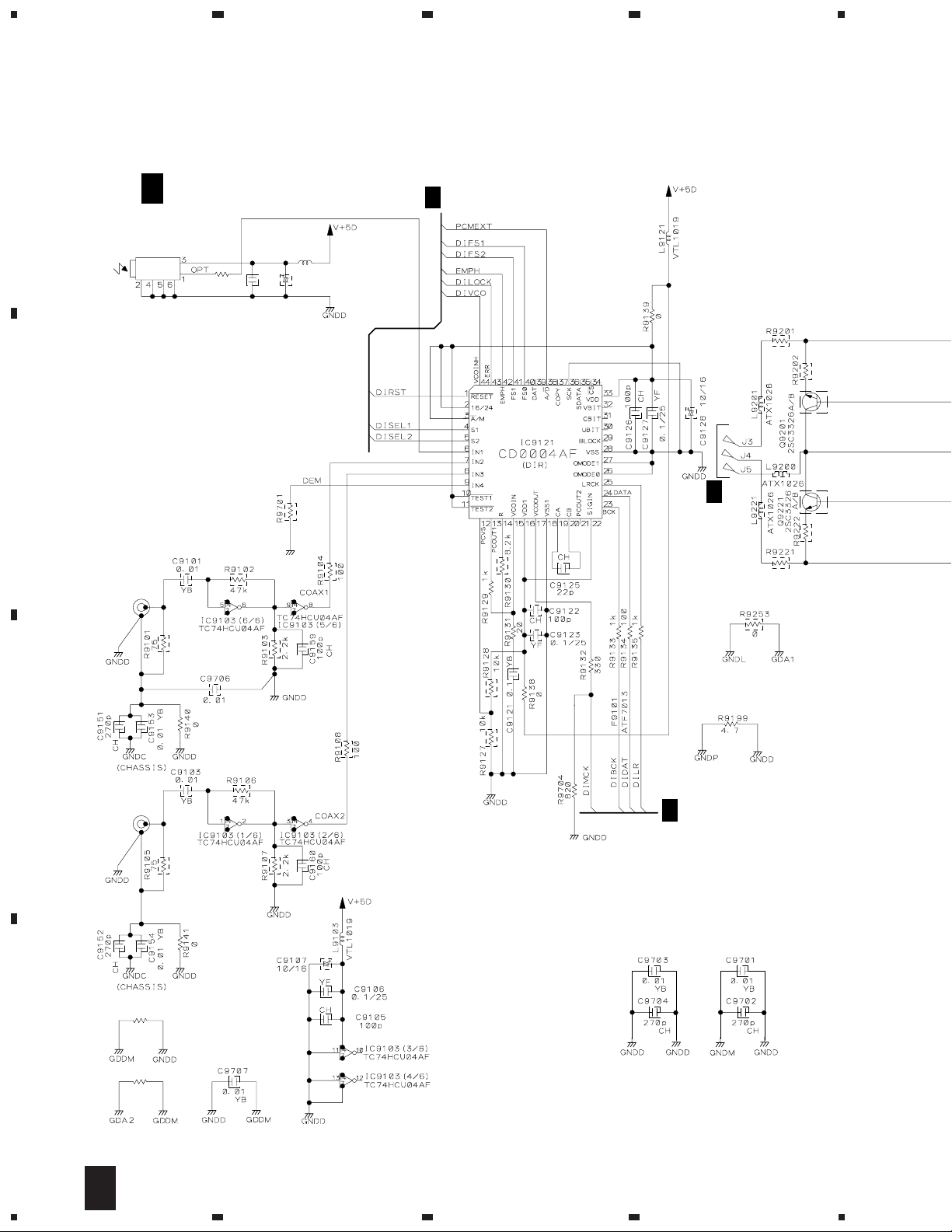
VSX-D607S
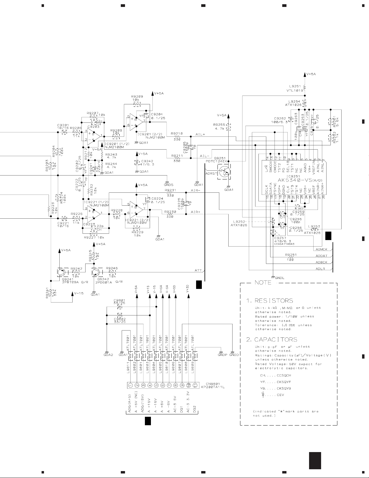
3.6 DOLBY DIGITAL ASSY (1/3)
A
DOLBY DIGITAL ASSY
1/3
H
(AWX7042)
23
H
2/3
4
TORX176
JA9104
R9111
100
C9110
B
JA9000
(2/2)
AKB7095
0.1
VTL1019
L9108
YF
C9111
47/6.3
6.2k
3.9k
H
0
3/3
3.9k
6.2k
C
JA9000
(1/2)
AKB7095
R9039
0
D
18
R9038
0
H
1/3
1234
H
2/3
5
678
VSX-D607S
A
B
H
2/3
H
2/3
C
D
CN212
C
2/3
H
1/3
5
6
7
8
19

1
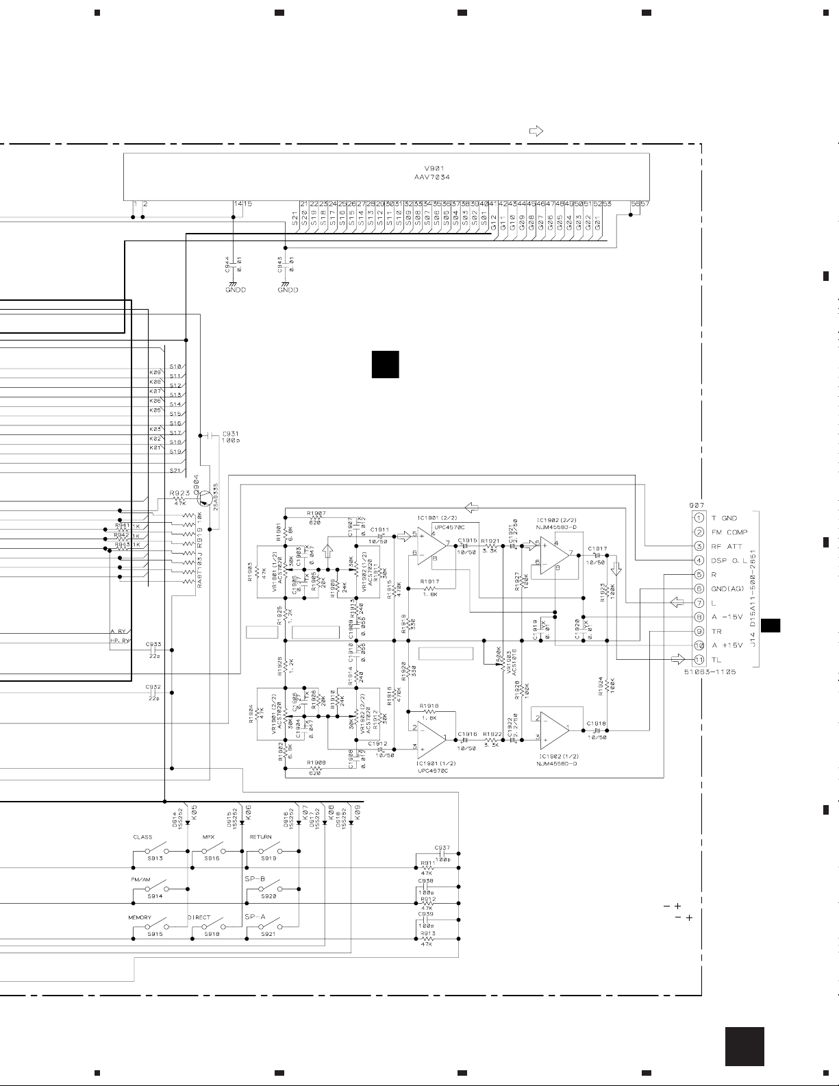
VSX-D607S
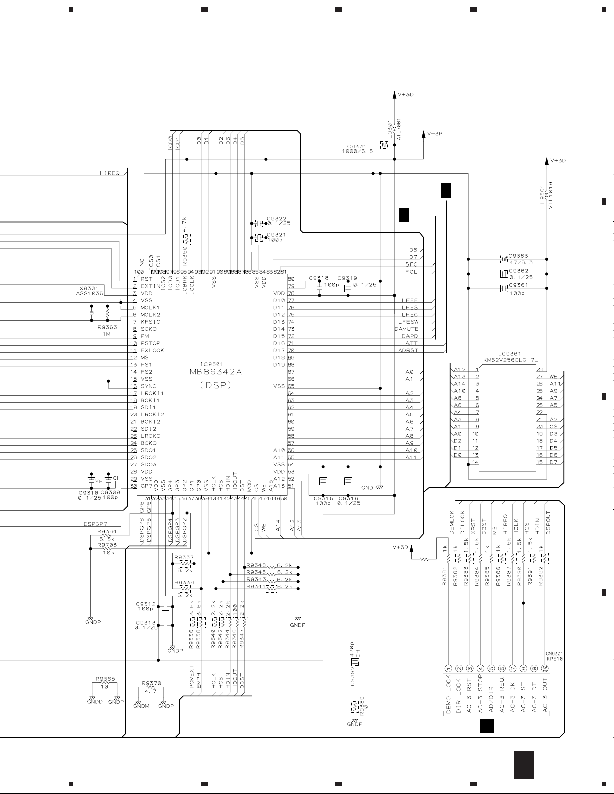
3.7 DOLBY DIGITAL ASSY (2/3)
A
DOLBY DIGITAL ASSY
2/3
H
B
(AWX7042)
23
H
1/3
H
3/3
4
C
D
20
H
2/3
1234
5
678
VSX-D607S
A
H
1/3
H
3/3
B
C
R9702
0
D
A
J23
H
2/3
5
6
7
8
21
 Loading...