

Page 1

AUDIO/VIDEO MULTI-CHANNEL
AMPLIFIER
VSA-AX10Ai
Operating Instructions
Page 2
IMPORTANT
CAUTION
RISK OF ELECTRIC SHOCK
DO NOT OPEN
The lightning flash with arrowhead symbol,
within an equilateral triangle, is intended to
alert the user to the presence of uninsulated
"dangerous voltage" within the product's
enclosure that may be of sufficient
magnitude to constitute a risk of electric
shock to persons.
CAUTION:
TO PREVENT THE RISK OF ELECTRIC
SHOCK, DO NOT REMOVE COVER (OR
BACK). NO USER-SERVICEABLE PARTS
INSIDE. REFER SERVICING TO QUALIFIED
SERVICE PERSONNEL.
The exclamation point within an equilateral
triangle is intended to alert the user to the
presence of important operating and
maintenance (servicing) instructions in the
literature accompanying the appliance.
D3-4-2-1-1_En
Replacement and mounting of an AC plug on the power supply cord of this unit should be performed only by qualified
service personnel.
The cut-off plug should be disposed of and must
IMPORTANT
FOR USE IN THE UNITED
KINGDOM
The wires in this mains lead are coloured in
accordance with the following code:
Blue : Neutral
Brown : Live
If the plug provided is unsuitable for your socket
outlets, the plug must be cut off and a suitable plug
fitted.
not be inserted into any 13 amp socket as this can
result in electric shock. The plug or adaptor or the
distribution panel should be provided with 10 A
fuse. As the colours of the wires in the mains lead
of this appliance may not correspond with coloured
markings identifying the terminals in your plug,
proceed as follows ;
The wire which is coloured blue must be connected
to the terminal which is marked with the letter N or
coloured black.
The wire which is coloured brown must be
connected to the terminal which is marked with the
letter L or coloured red.
Thank you for buying this pioneer product.
Please read through these operating
instructions so you will know how to
operate your model properly. After you
have finished reading the instructions, put
them away in a safe place for future
reference.
VENTILATION: When installing this unit, make
sure to leave space around the unit for ventilation
to improve heat radiation (at least 60 cm at top, 10
cm at rear, and 30 cm at each side).
WARNING: Slot and openings in the cabinet are
provided for ventilation and to ensure reliable
operation of the product and to protect it from
overheating, to prevent fire hazard, the openings
should never be blocked and covered with items,
Do not connect either wire to the earth terminal of a
three pin plug.
NOTE
After replacing or changing a fuse, the fuse cover in
the plug must be replaced with a fuse cover which
corresponds to the colour of the insert in the base
of the plug or the word that is embossed on the
base of the plug, and the appliance must not be
used without a fuse cover. If lost replacement fuse
covers can be obtained from your dealer.
Only 10 A fuses approved by B.S.I or A.S.T.A to
B.S.1362 should be used.
D3-4-2-1-2-2_En
such as newspapers, table-cloths, curtains, etc. Also
WARNING:
BEFORE PLUGGING IN THE UNIT FOR THE FIRST
do not put the apparatus on the thick carpet, bed,
sofa, or fabric having a thick pile.
D3-4-2-1-7b_En
TIME, READ THE FOLLOWING SECTION CAREFULLY.
The voltage of the available power supply differs
according to country or region. Be sure that the
power supply voltage of the area where this unit
will be used meets the required voltage (e.g., 230V
or 120V) written on the rear panel.
D3-4-2-1-4_En
WARNING: No naked flame sources, such as
lighted candle, should be placed on the apparatus.
If naked flame sources accidentally fall down, fire
spread over the apparatus then may cause fire.
D3-4-2-1-7a_En
This product complies with the Low Voltage Directive
(73/23/EEC, amended by 93/68/EEC), EMC Directives
(89/336/EEC, amended by 92/31/EEC and
93/68/EEC).
D3-4-2-1-9a_En
WARNING: The apparatus is not waterproofs, to
prevent fire or shocks hazard, do not expose this
apparatus to rain or moisture and do not put any
water source near this apparatus, such as vase,
flower pot, cosmetics container and medicine
bottle etc.
D3-4-2-1-3_En
Operating Environment
Operating environment temperature and humidity:
+5 ºC – +35 ºC (+41 ºF – +95 ºF); less than 85 %RH
(cooling vents not blocked)
Do not install in the following locations
• Location exposed to direct sunlight or strong artificial
light
• Location exposed to high humidity, or poorly
ventilated location
D3-4-2-1-7c_En
Page 3

This product is for general household purposes. Any
failure due to use for other than household purposes
(such as long-term use for business purposes in a
restaurant or use in a car or ship) and which
requires repair will be charged for even during the
warranty period.
K041_En
If the socket outlets on the associated equipment
are not suitable for the plug supplied with the
product, the plug must be removed and appropriate
one fitted. Replacement and mounting of an AC plug
on the power supply cord of this unit should be
perfomed only by qualified service personnel. The
cut-off plug must be disposed of as an electrical
shock hazard could exist if connected to a socket
outlet.
D3-4-2-2-1a_En
The OFF/ON switch is secondary connected and
therefore, does not separate the unit from mains
power in OFF position. Therefore install the unit
suitable places easy to disconnect the MAINS plug
in case of the accident. The MAINS plug of unit
should be unplugged from the wall socket when left
unused for a long period of time.
D3-4-2-2-2a_En
Page 4

Contents
Our philosophy
Features
. . . . . . . . . . . . . . . . . . . . . . . . . . . . . . 6
. . . . . . . . . . . . . . . . . . . . . . . . . . . . . . . . . . . 6
01 Before you start
Checking the supplied accessories
Using the remote control
Operating range of the remote control
Recharging the remote control
Setting up the remote control
Calibrating the remote control screen
Setting the clock
Setting the button alert volume
Setting the time-out setting
Resetting the remote control
Locking the remote control
Restarting the remote control
Replacing the lithium-ion batteries
. . . . . . . . . . . . . . . . . . . . . . 7
. . . . . . . . . . . . . . . . . . . . . . . . . . . 9
. . . . . . . . . . . . . . 7
. . . . . . . . . . . 7
. . . . . . . . . . . . . . . . 7
. . . . . . . . . . . . . . . . . . 8
. . . . . . . . . . . 8
. . . . . . . . . . . . . . . . 9
. . . . . . . . . . . . . . . . . . . 9
. . . . . . . . . . . . . . . . . 10
. . . . . . . . . . . . . . . . . . 10
. . . . . . . . . . . . . . . . 10
. . . . . . . . . . . . 11
02 Connecting your equipment
Rear panel
When making cable connections
Connecting your TV
Connecting a DVD player
Connecting the multichannel analog outputs
Connecting a satellite/cable amplifier or other
set-top box
Connecting a VCR or DVD recorder
Connecting other video sources
Using the component video jacks
About the video converter
Connecting digital audio sources
Connecting analog audio sources
Connecting a component to the front panel inputs
Installing your speaker system
Connecting the speakers
Placing the speakers
Plugging in the amplifier
About the AC outlet
. . . . . . . . . . . . . . . . . . . . . . . . . . . . . . . . 12
. . . . . . . . . . . . . . . 13
. . . . . . . . . . . . . . . . . . . . . . . . . 14
. . . . . . . . . . . . . . . . . . . . . 15
. . . . 16
. . . . . . . . . . . . . . . . . . . . . . . . . . . . . . . . 17
. . . . . . . . . . . . . 18
. . . . . . . . . . . . . . . . 19
. . . . . . . . . . . . . . . 20
. . . . . . . . . . . . . . . . . . . . . 20
. . . . . . . . . . . . . . . 21
. . . . . . . . . . . . . . 22
. . . . . . . . . . . . . . . . . 24
. . . . . . . . . . . . . . . . . . . . 24
. . . . . . . . . . . . . . . . . . . . . . . 25
. . . . . . . . . . . . . . . . . . . . . 26
. . . . . . . . . . . . . . . . . . . . . . . . 26
03 Controls and displays
Display
. . . . . . . . . . . . . . . . . . . . . . . . . . . . . . . . . . . 27
Front panel
Remote control
Basic remote control displays
Remote control displays for other components
. . . . . . . . . . . . . . . . . . . . . . . . . . . . . . . . 28
. . . . . . . . . . . . . . . . . . . . . . . . . . . . . 30
. . . . . . . . . . . . . . . . 30
04 Getting started
Introduction to home theater
Automatically setting up for surround sound
Other problems when using the Auto Surround
. . . . . . . . . . . . . . . . . . . . . . . . . . . . . . . . . . . 37
Setup
. . . . . . . . . . . . . . . . . . 35
. . . . . . 35
. . 23
. . . 32
Checking the settings on your DVD (or other)
. . . . . . . . . . . . . . . . . . . . . . . . . . . . . . . . . . . . 37
player
Playing a source
. . . . . . . . . . . . . . . . . . . . . . . . . . . . 37
05 Listening to your system
About the listening modes
Listening in surround sound
Using the Advanced surround effects
Using the Home THX modes
Listening in stereo
Listening with headphones
Using the multichannel analog inputs
Using the Stream Direct mode
Listening with Acoustic Calibration EQ
Selecting the input signal type
Selecting USB and multichannel analog
input channels
Listening to high-sampling formats
Using the surround back channel
Listening with virtual surround back speakers
Creating a center speaker effect
Using Hi-bit and Hi-sampling
Using Midnight and Loudness listening
Using the tone control
Switching the tone control on or off
Adjusting the bass and treble
Reducing noise during playback
Listening to dual mono soundtracks
. . . . . . . . . . . . . . . . . . . . . . . . . . . . 45
. . . . . . . . . . . . . . . . . . . . 39
. . . . . . . . . . . . . . . . . 39
. . . . . . . . . . 41
. . . . . . . . . . . . . . . . . 41
. . . . . . . . . . . . . . . . . . . . . . . . . 42
. . . . . . . . . . . . . . . . . . . . 42
. . . . . . . . . . . 43
. . . . . . . . . . . . . . . . . 43
. . . . . . . . . . . 44
. . . . . . . . . . . . . . . . . 44
. . . . . . . . . . . . . 45
. . . . . . . . . . . . . . 46
. . . . . 47
. . . . . . . . . . . . . . . . 47
. . . . . . . . . . . . . . . . . . 48
. . . . . . . . . . 48
. . . . . . . . . . . . . . . . . . . . . . . 48
. . . . . . . . . . . . 48
. . . . . . . . . . . . . . . . 49
. . . . . . . . . . . . . . . . 49
. . . . . . . . . . . . . 50
06 The Surround Setup menu
Making amplifier settings from the Surround Setup
. . . . . . . . . . . . . . . . . . . . . . . . . . . . . . . . . . . . 51
menu
Speaker Systems
Channel Level
Speaker Distance
Acoustic Calibration EQ
Professional Acoustic Calibration EQ
X-Curve
Checking your surround settings
. . . . . . . . . . . . . . . . . . . . . . . . . . . . . . . . . 59
. . . . . . . . . . . . . . . . . . . . . . . . . . 52
. . . . . . . . . . . . . . . . . . . . . . . . . . . . . 54
. . . . . . . . . . . . . . . . . . . . . . . . . . 55
. . . . . . . . . . . . . . . . . . . . . 55
. . . . . . . . . . . 57
. . . . . . . . . . . . . . . 60
07 Controlling other equipment
Using the remote control with other components
Recalling preset codes
Programming signals from other remote controls
Remote Direct function
Editing remote control button names
Multi Operation and System Off
Programming a multi operation or a shutdown
sequence
Switching components on and off using the 12
volt trigger
. . . . . . . . . . . . . . . . . . . . . . . . . . . . . . . . 66
. . . . . . . . . . . . . . . . . . . . . . . . . . . . . . . . 68
. . . . . . . . . . . . . . . . . . . . . . . 61
. . . . . . . . . . . . . . . . . . . . . . 64
. . . . . . . . . . . . 64
. . . . . . . . . . . . . . . . 66
. . . 61
. . 63
4
En
Page 5

Operating other Pioneer components with this
unit’s sensor
. . . . . . . . . . . . . . . . . . . . . . . . . . . . . . 68
08 Using other functions
Making an audio or a video recording
Monitoring your recording
Reducing the level of an analog signal
Adjusting the delay of a soundtrack
Watching video and audio sources independently
Enhancing SACD playback
Using the A/D converters to give greater definition to 2channel sound
Dimming the display
Switching the speaker impedance
Checking your system settings
Resetting the system
Default amplifier settings
. . . . . . . . . . . . . . . . . . . . . . . . . . . . . 71
. . . . . . . . . . . . . . . . . . . 69
. . . . . . . . . . . . . . . . . . . 71
. . . . . . . . . . . . . . . . . . . . . . . . 72
. . . . . . . . . . . . . . . . . . . . . . . . 73
. . . . . . . . . . . . . . . . . . . 73
. . . . . . . . . . . 69
. . . . . . . . . . 70
. . . . . . . . . . . . . 70
. . 70
. . . . . . . . . . . . . . 72
. . . . . . . . . . . . . . . . 73
09 Other connections
Using speaker system B
Switching the speaker system
Using speaker system B in another room
Alternating surround speaker setups using
speaker system B (ITU-R)
Bi-amping your front speakers
Bi-wiring your speakers
Adding a second set of surround speakers for
Bi-Surround
Using the pre-outs
Connecting additional amplifiers
Connecting an external stereo pre-amplifier
Using the i.LINK interface
About i.LINK
About PQLS rate control
Creating an i.LINK network
Using the USB interface
Connecting a PC for Advanced MCACC output
Advanced MCACC output using your PC
. . . . . . . . . . . . . . . . . . . . . . . . . . . . . . . 77
. . . . . . . . . . . . . . . . . . . . . . . . . . . . . . 79
. . . . . . . . . . . . . . . . . . . . . 75
. . . . . . . . . . . . . . . . 75
. . . . . . . 75
. . . . . . . . . . . . . . . . . . . 76
. . . . . . . . . . . . . . . . . 76
. . . . . . . . . . . . . . . . . . . . . . 77
. . . . . . . . . . . . . . . . . . . . . . . . . . 77
. . . . . . . . . . . . . . 77
. . . . . 78
. . . . . . . . . . . . . . . . . . . . 78
. . . . . . . . . . . . . . . . . . . . 79
. . . . . . . . . . . . . . . . . . 79
. . . . . . . . . . . . . . . . . . . . . 80
. . . . 81
. . . . . . . . 82
THX Audio Setup . . . . . . . . . . . . . . . . . . . . . . . . . . . 88
THX Ultra2 Subwoofer Setup . . . . . . . . . . . . . . . . . 89
Surround Back Speaker Position. . . . . . . . . . . . . . 89
11 Additional information
Optimizing your speaker setup . . . . . . . . . . . . . . . . 90
Basic surround setup . . . . . . . . . . . . . . . . . . . . . . 90
THX speaker system setup . . . . . . . . . . . . . . . . . . 91
Speaker system setup for DVD-Audio/
multichannel music sources . . . . . . . . . . . . . . . . . 91
Troubleshooting. . . . . . . . . . . . . . . . . . . . . . . . . . . . 92
Power . . . . . . . . . . . . . . . . . . . . . . . . . . . . . . . . . . 92
No sound . . . . . . . . . . . . . . . . . . . . . . . . . . . . . . . 92
Other audio problems . . . . . . . . . . . . . . . . . . . . . . 94
Video . . . . . . . . . . . . . . . . . . . . . . . . . . . . . . . . . . . 95
Settings. . . . . . . . . . . . . . . . . . . . . . . . . . . . . . . . . 96
Remote control . . . . . . . . . . . . . . . . . . . . . . . . . . . 96
Display . . . . . . . . . . . . . . . . . . . . . . . . . . . . . . . . . 97
i.LINK interface . . . . . . . . . . . . . . . . . . . . . . . . . . . 98
i.LINK messages . . . . . . . . . . . . . . . . . . . . . . . . . . 98
USB interface . . . . . . . . . . . . . . . . . . . . . . . . . . . . 99
Miscellaneous . . . . . . . . . . . . . . . . . . . . . . . . . . . . 99
Surround sound formats . . . . . . . . . . . . . . . . . . . . 100
Dolby. . . . . . . . . . . . . . . . . . . . . . . . . . . . . . . . . . 100
DTS . . . . . . . . . . . . . . . . . . . . . . . . . . . . . . . . . . . 100
Windows Media® Audio 9 Professional . . . . . . . 101
PCM (Pulse Code Modulation) . . . . . . . . . . . . . . 101
About THX® . . . . . . . . . . . . . . . . . . . . . . . . . . . . . 101
Maintenance of external surfaces . . . . . . . . . . . . . 102
Specifications . . . . . . . . . . . . . . . . . . . . . . . . . . . . 103
10 Advanced setup
The Input Assign menu . . . . . . . . . . . . . . . . . . . . . . 83
Assigning the digital inputs. . . . . . . . . . . . . . . . . . 83
Assigning the component video inputs . . . . . . . . . 84
Assigning the i.LINK inputs. . . . . . . . . . . . . . . . . . 84
Assigning the video inputs . . . . . . . . . . . . . . . . . . 85
The Expert Setup menu . . . . . . . . . . . . . . . . . . . . . . 85
OSD Adjustment . . . . . . . . . . . . . . . . . . . . . . . . . . 86
Bass Peak Level. . . . . . . . . . . . . . . . . . . . . . . . . . . 86
Dynamic Range Control . . . . . . . . . . . . . . . . . . . . 87
Function Rename . . . . . . . . . . . . . . . . . . . . . . . . . 87
OSD Overlay . . . . . . . . . . . . . . . . . . . . . . . . . . . . . 87
12 Volt Trigger . . . . . . . . . . . . . . . . . . . . . . . . . . . . 88
5
En
Page 6

Our philosophy
Pioneer is dedicated to making your home theater
listening experience as close as possible to the vision of
the moviemakers and mastering engineer when they
created the original soundtrack. We do this by focusing
on three important steps:
1 Achieving the highest possible sound quality
2 Allowing for customized acoustic calibration
according to any listening area
3 Fine-tuning the amplifier with the help of worldclass studio engineers
1
Features
Easy setup using Advanced MCACC
Setting up for home theater sound is as easy as
connecting your speakers, a DVD player or other source,
and your TV. The Auto Surround Setup provides a quick
but accurate surround sound setup, while for complete
surround sound control you still have access to the full
range of surround sound settings.
In addition, the Professional Acoustic Calibration EQ
setup measures the reverb characteristics of your
listening area, allowing you to customize your system
calibration with the help of a graphical output that can be
displayed on-screen, or using a computer.
i.LINK digital interface
The i.LINK interface makes it possible to connect this
amplifier to i.LINK-equipped components, allowing you
to enjoy high sampling rate (up to 192kHz) PCM
multichannel digital audio from DVD-Audio and SACD
discs, as well as digital audio from DVD-Video, CD and
Video CD discs, all with a single cable.
USB digital interface
It is possible to listen to multichannel audio sources from
your computer by connecting to the USB interface on the
rear of this amplifier. Depending on your model of
computer and the software installed, you can listen to
any source compatible with your operating system
through the speaker setup connected to this amplifier.
Dolby Pro Logic IIx and DTS Neo:6 decoders
The built-in Dolby Pro Logic IIx and DTS Neo:6 decoders
not only provide full surround sound decoding for Dolby
Surround sources, but will also generate convincing
surround sound for any stereo source.
THX certified design
This amplifier is THX Ultra2™ certified, allowing you to
take advantage of new THX technologies such as ASA
(Advanced Speaker Array), which can process any 5.1
channel source for 6.1 channel (THX Surround EX) or 7.1
channel (THX Ultra2™ Cinema and THX MusicMode)
playback. These features are also available when using
the i.LINK interface.
Windows Media® Audio 9 Professional decoding
It is possible to listen to the Windows Media® Audio 9
Professional (WMA9 Pro) discrete surround format using
the on-board WMA9 Pro decoder, or through the USB
connection using a software decoder on your computer.
Seamless video conversion
With the Pioneer video converter, you can use a wide
range of cords interchangeably, giving you more
flexibility when making video connections.
Easy-to-use remote control
The remote control gives you not only complete control
over every function of this amplifier, but also over the
main functions for other components in your home
theater system. Using a system of preset codes, you can
program the remote to operate a wide range of other
equipment.
Energy-saving design
This amplifier is designed to use less than 0.65 W of
energy when in standby.
1
With the cooperation of AIR Studios, this amplifier has
been designated AIR Studios Monitor Reference:
6
En
Dolby Digital and DTS decoding, including Dolby
Digital EX, DTS 96/24 and DTS-ES
Dolby Digital and DTS decoding brings theater sound
right into your home with up to six channels of surround
sound, including a special LFE (Low Frequency Effects)
channel for deep, realistic sound effects.
With the addition of a surround back speaker, you can
take advantage of the built-in Dolby Digital EX and DTSES decoders for six-channel surround sound.
“i.LINK” and the i.LINK logo are trademarks of the Sony
Corporation.
Page 7
Before you start
Chapter 1
Before you start
01
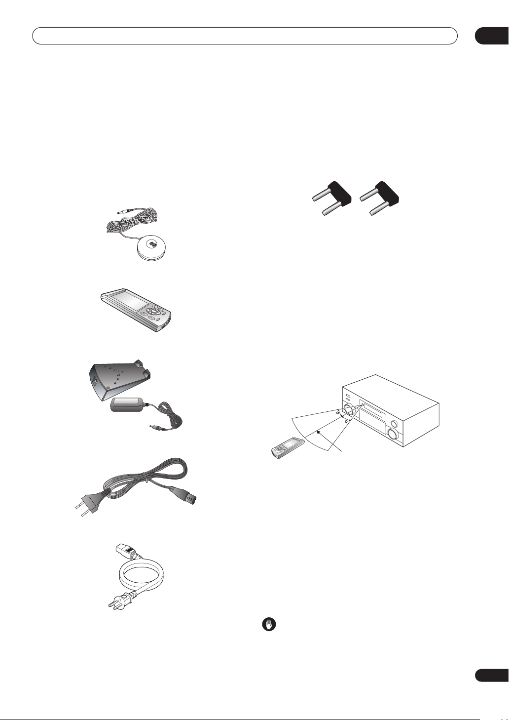
Checking the supplied accessories
Please check that you've received the following supplied
accessories:
• Microphone
• Remote control unit
• Remote control unit recharger and AC adapter
• U-shaped connectors x2 (attached to back of
amplifier — see item 8 in Rear panel on page 12)
• Calibration disc
• Multi-channel audio speaker setting guide
• These operating instructions
Using the remote control
Keep the following in mind when using the remote
control:
Operating range of the remote control
• Make sure that there are no obstacles between the
remote and the remote sensor on the unit.
• The remote has a range of about 7 meters.
30
30
• AC adapter cord
• Power cord
7m
• Remote operation may become unreliable if strong
sunlight or fluorescent light is shining on the unit’s
remote sensor.
• Remote controllers for different devices can interfere
with each other. Avoid using remotes for other
equipment located close to this unit.
Recharging the remote control
When the battery indicator on the remote control display
shows that the rechargeable battery is almost depleted,
recharge the remote as shown below. To make sure the
battery doesn’t run out completely, simply leave the
remote control in the recharger when not in use.
Caution
• Do not use AC adapters or AC adapter cords other
than the one supplied.
7
En
Page 8
01
Before you start
• Do not use the AC adapter or AC adapter cord for any
other purpose than those specified below.
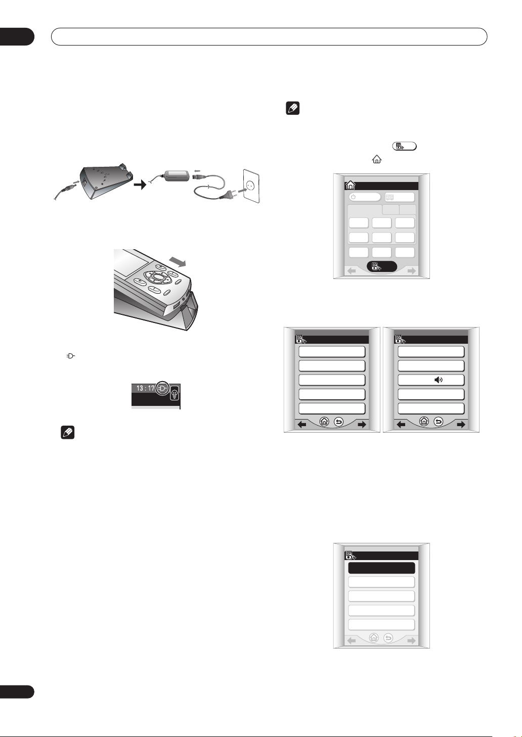
1 Connect the AC adapter cord then connect the
adapter to the recharger and plug it into an AC
outlet.
2 Place the remote control on the recharger,
aligning the indent on the bottom of the remote
with the tabs on the recharger.
• When the remote control is recharging, you’ll see the
indicator appear in the upper right corner of the
display:
Note
• The remote control operations in this section are
accessed from the remote setup menu. To go to the
remote setup menu, press from the remote
SETUP
control Home menu ( ):
AMPLIFIER
TV
/ DVD
CD TUNER
MULTI
OPERATION
SETUP
1/3
SAT
SYSTEM
OFF
HOME
AMPLIFIER
INPUT 1 2 3
DVR
/ LD
DVR
/ VCR1
TV
CONT
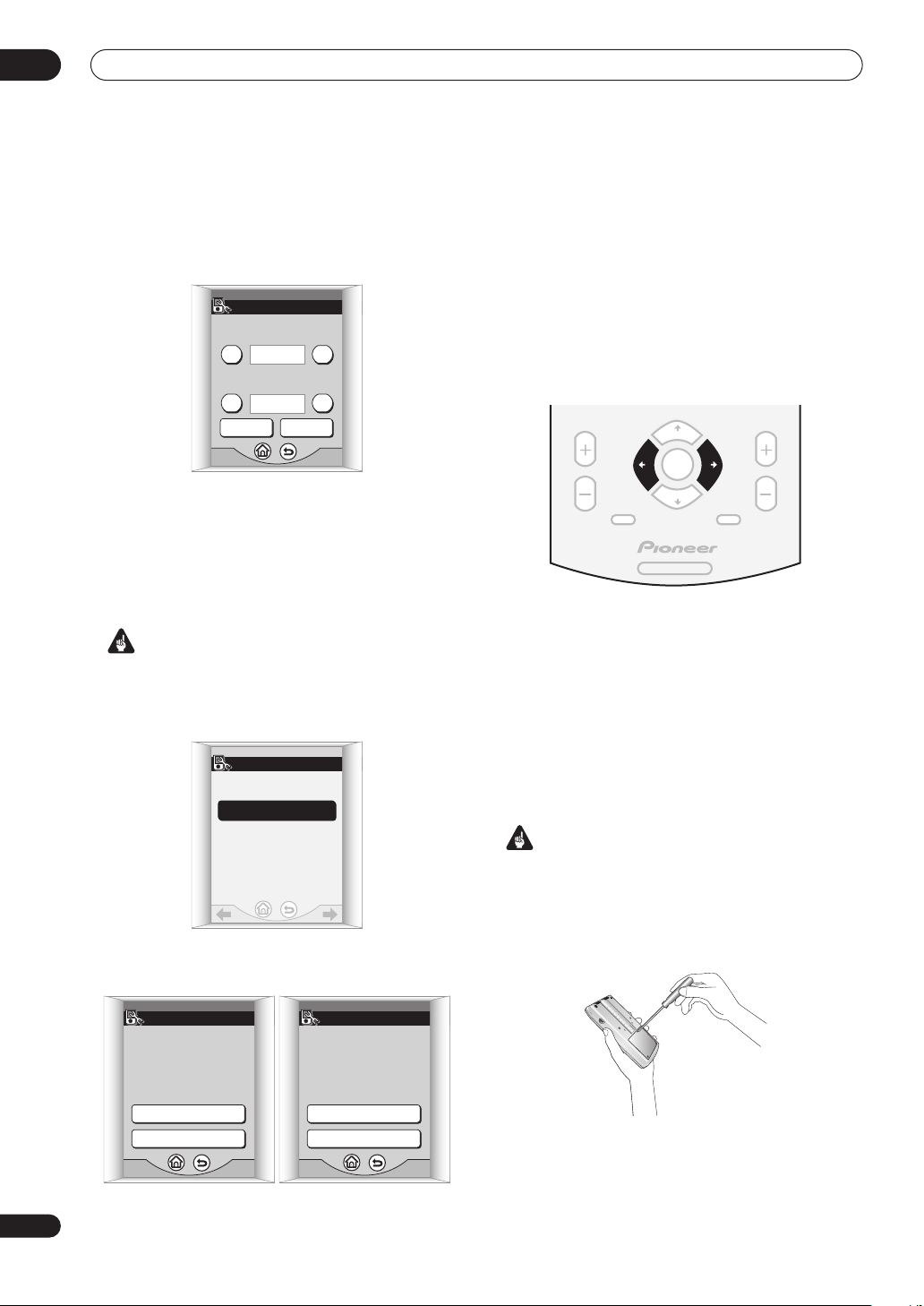
There are three remote setup menu screens, which
can be navigated by using the touch panel /
(cursor left/right) soft keys:
1/3SETUP
CALIBRATE
PRESET RECALL
LEARNING
MULTI OPERATION
DIRECT FUNCTION
SETUP 2/3
CLOCK DISPLAY : AM/PM
CLOCK SETTING
BEEP :
TIMEOUT
KEY LABEL
8
En
Note
• If the remote hasn’t been charged for awhile, the
remote control display may remain blank for several
minutes before the touch screen appears. If it
continues to remain blank, try lifting the remote
control up from the recharger and reseating it on the
recharger. If after several tries, this does not work,
see Replacing the lithium-ion batteries on page 11.
Setting up the remote control
After you have calibrated the screen and set the display
clock, use the other settings to customize your remote
control.
• For more on navigating the remote control menu
screens, see Basic remote control displays on
page 30.
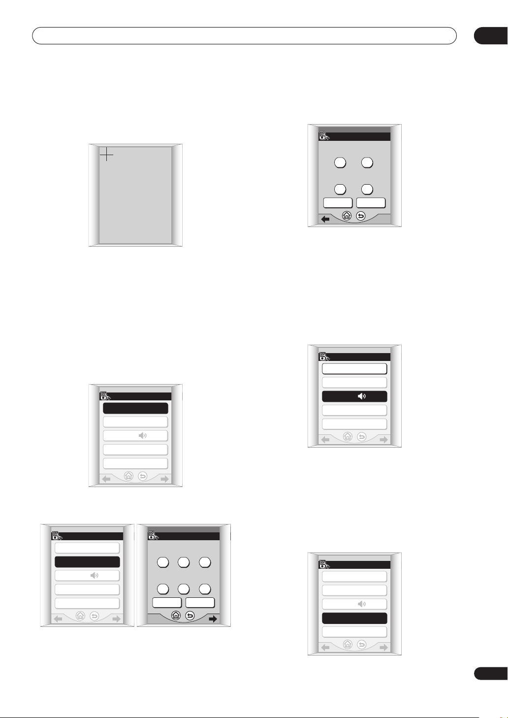
Calibrating the remote control screen
This will make sure the remote control responds correctly
when you touch it.
1 Press CALIBRATE.
SETUP 1/3
CALIBRATE
PRESET RECALL
LEARNING
MULTI OPERATION
DIRECT FUNCTION
Page 9
Before you start
01
2 Press the center of each cross point to align the
touch screen with the LCD panel underneath.
This adjustment will make sure your remote control is
calibrated correctly.
PLEASE TOUCH
THE UPPER "+" MARK
"MUTE": CANCEL
When you've touched both cross points, PLEASE WAIT is
displayed and you’ll return to the remote setup menu
when calibration is finished.
Setting the clock
The remote control features a clock that shows both 12
and 24 hour formats.
1 Press CLOCK DISPLAY to select either AM/PM or
24H display format.
Each press switches between the two settings. The
current display format is shown after CLOCK DISPLAY.
SETUP 2/3
CLOCK DISPLAY : AM/PM
CLOCK SETTING
BEEP :
TIMEOUT
KEY LABEL
2 Press CLOCK SETTING to set the date.
Use the + and – buttons to set the year, month and day.
SETUP 2/3
CLOCK DISPLAY : AM/PM
CLOCK SETTING
BEEP :
TIMEOUT
KEY LABEL
DATE
+++
2003 /10 /09
---
1/2
CANCELNEXT
3 Press NEXT to continue and set the time.
Use the + and – buttons to set the hour and minute.
TIME
++
17 : 08
--
2/2
CANCELENTER
4 Press ENTER when you’re finished.
You’ll return to the remote setup menu.
Setting the button alert volume
You can set the volume of the ‘beep’ you hear when you
press a button on the remote.
• Press BEEP to select a setting.
Each press selects between quiet, loud or off. The current
setting is shown on the touch screen.
SETUP 2/3
CLOCK DISPLAY : AM/PM
CLOCK SETTING
BEEP :
TIMEOUT
KEY LABEL
Setting the time-out setting
• Default setting: 60sec
To save battery life, a timer automatically switches off the
remote control off after a set amount of time if no
commands are entered. You can adjust separate timeout settings for the LCD, and the remote backlight.
1 Press TIMEOUT.
SETUP 2/3
CLOCK DISPLAY : AM/PM
CLOCK SETTING
BEEP :
TIMEOUT
KEY LABEL
En
9
Page 10
01
Before you start
2 Use the + and – buttons to set the LCD TIMEOUT
and BACKLIGHT TIMEOUT settings.
You can adjust these from 20–120 seconds.
• The backlight timeout can’t be longer than the LCD
timeout setting.
TIMEOUT
LCD TIME OUT
-
60 sec
BACKLIGHT TIME OUT
60 sec
-
+
+
CANCELENTER
3 Press ENTER when you’re finished.
You’ll return to the remote setup menu.
Resetting the remote control
Use this feature to reset the remote control settings to
the factory defaults.
Important
• Doing this will erase any of your personalized
settings.
1 Press RESET TO DEFAULT.
SETUP 3/3
RESET TO DEFAULT
After the screen goes blank, the Home menu appears
within a minute or so, and the remote control will be reset
to the default settings.
Locking the remote control
This amplifier has a remote control lock feature that
makes the remote control touch screen and hard keys
inoperative.
1 At the same time, press the and hard keys
for about three seconds.
• This is not possible from the remote setup screen.
CHANNEL VOLUME
ENTER
MENU MUTE
SYSTEM
SETUP
AV AMPLIFIRE
LOCKED! shows on the touch screen to indicate the
remote control is locked.
2 To unlock the remote control, repeat step 1.
Once the remote control is unlocked, the touch screen
shows the Home menu.
Restarting the remote control
If the remote control display freezes during operation
(none of the buttons seem to work), you may need to
restart the unit.
10
En
2 Confirm by pressing YES after reading each
screen.
RESET
Do you want to reset
the REMOTE to the
DEFAULT settings ?
YES
NO
RESET
ALL settings you made
will be ERASED.
Is it all right?
YES
NO
Important
• Doing this will not erase any of your personalized
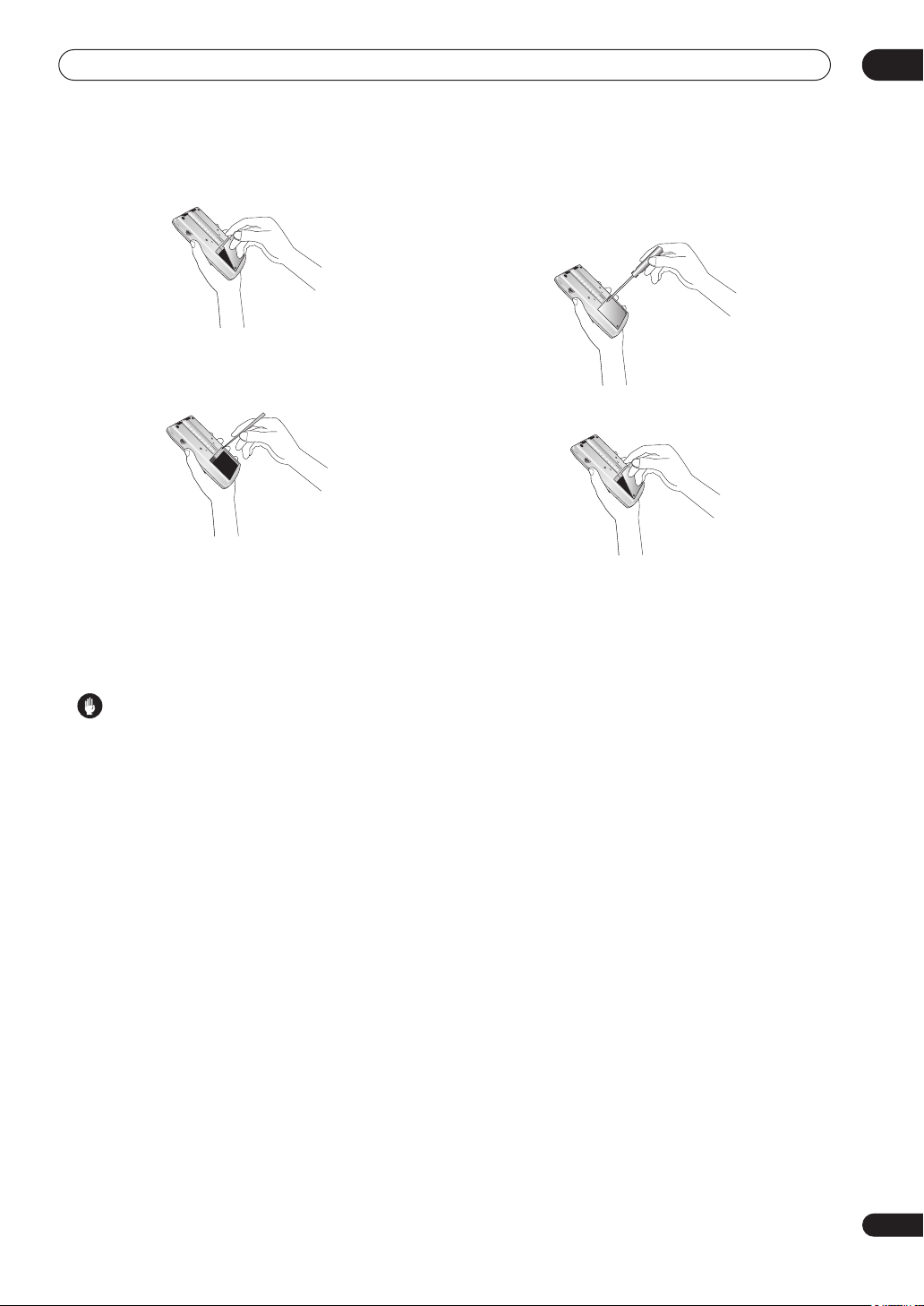
settings or presets.
1 Use a small phillips screwdriver to remove the
screw fixing the battery cover to the back of the
remote.
Page 11
Before you start
RESET
01
2 Remove the battery cover.
3 Use a pen or other sharp instrument to press the
reset button located in the hole to the right (above
the battery).
RESET
RESET
After restarting the remote control, the touch screen
shows the Home menu.
Replacing the lithium-ion batteries
If you notice that the remote will no longer hold a charge,
you may need to replace the lithium-ion battery cells.
Caution
• The lithium-ion batteries may present a fire or
chemical burn hazard if misused. Do not
disassemble, heat above 100˚C (212˚F), or
incinerate.
• Replacement cells must be of type AZW7264,
manufactured by NEC TOKIN Corporation. Use of any
other battery cells may result in fire or explosion.
Contact the Pioneer Service Center specified on your
warranty card to obtain new batteries. Replacement
cells are not covered under warranty.
• Dispose of used battery cells immediately after
replacement. Keep away from children.
• When disposing of used batteries, please comply
with governmental regulations or environmental
public institution’s rules that apply in your country or
area.
1 Use a small phillips screwdriver to remove the
screw fixing the battery cover to the back of the
remote.
2 Remove the battery cover.
3 Disconnect the old battery cell from the unit.
Do not pull the connector out by holding onto the
attached wires. Hold the connector firmly with your
fingers, or use a small screwdriver (or other sharp tool) to
disconnect it.
4 Connect the new battery cell.
Push the connector in until it is fully inserted. Make sure
you keep the wire out of the way and line up the cell
properly so that the battery cover can be closed easily.
11
En
Page 12
02
T
C
R
SUR-ROUND
SUR-
SPEAK
12V TRIGGER
V
X
N
3
AC IN
AC OUTLET
X
VIDEO
Connecting your equipment
Chapter 2
Connecting your equipment
This amplifier provides you with almost limitless possibilities for connecting your audio/video system, but it doesn’t
have to be difficult. Depending on your needs, you could be up and running in no time after a few simple connections.
This section has been designed so that you can read through this short introduction, then jump to the specific
connections that you need to make. For a basic home theater setup, you may only need to look through the TV, DVD
and speaker connections.
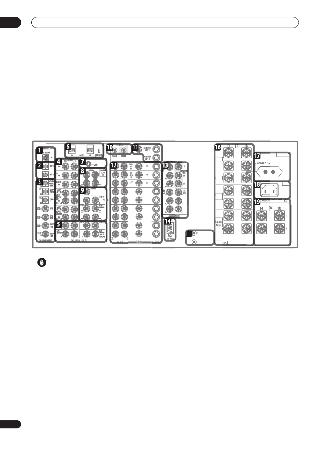
Rear panel
OUT
OUT
DVR/
VCR1
IN
IN
OUT
OUT
VCR2
IN
IN
OUT
OUT
VCR
I
Caution
• Before making or changing the connections, switch
off the power and disconnect the power cord from the
power outlet. Plugging in components should be the
last connection you make with your system.
1 USB audio input
The USB audio input allows you to use your PC as a
playback source for stereo or multichannel digital audio.
See Using the USB interface on page 80 for connection
details.
2 Digital audio outputs
Two optical digital audio outputs for connecting to a CD,
MD or other digital recorder. See Connecting a VCR or
DVD recorder on page 18 for connection details.
3 Digital audio inputs
Three optical and three coaxial digital audio inputs for
connecting digital audio sources to this amplifier.
There’s also a 2 RF IN jack for connection to an LD
player with a 2 RF output.
All the inputs are freely assignable to input functions for
maximum flexibility.
DC OUT 12
TOTAL 100mA MA
FRON
ENTE
(Single)
W MA
• If a connected component does not correspond to
the input function (DVD/LD, etc.), see Assigning the
digital inputs on page 83 to assign it properly.
4 Stereo analog audio source inputs/outputs
Five sets of analog audio jacks for connection to audio
sources such as CD players, tape decks, turntables, or a
radio tuner. The CD-R/TAPE 1/MD and TAPE 2
MONITOR functions also feature outputs for recording.
See Connecting analog audio sources on page 22 for
connection details.
5 Multichannel analog audio inputs
7.1 channel analog inputs for connection to a DVD player
with multichannel analog outputs. See Connecting the
multichannel analog outputs on page 16 for connection
details.
6 i.LINK connectors
Two S400-type i.LINK connectors allow you to connect
this amplifier to other compatible i.LINK audio devices
for high-resolution, multichannel digital audio input/
output. See Using the i.LINK interface on page 78 for
connection details.
12
En
Page 13
Connecting your equipment
02
7 Turntable ground
A grounding (earth) terminal for use with turntables that
require it. See Connecting analog audio sources on
page 22 for connection details.
8 Pre-amplifier output/power amplifier input
Do not remove the U-shaped connectors unless you plan
to connect an external power amp to this amplifier.
When using this amplifier as an integrated amplifier,
leave the pre-amp outputs connected to the power amp
inputs with the supplied U-shaped connectors.
Removing these connectors allows you to use this unit as
a pre-amplifier or power amplifier only, or to integrate
another amplifier into your setup for more inputs. See
Using the pre-outs on page 77 for connection details.
9 Multichannel pre-amplifier outputs
Multichannel pre-amp outputs that you can use to
connect separate amplifiers for center, surround,
surround back and subwoofer channels. See Using the
pre-outs on page 77 for connection details.
10 Control input/output
Mini jack terminals for connection to other Pioneer
components to enable you to control all your equipment
from a single IR remote sensor. See Operating other
Pioneer components with this unit’s sensor on page 68
for connection details.
11 Monitor video outputs
Three video outputs consisting of a standard composite
video output and two S-video outputs, for connection to
monitors and TVs. See Connecting your TV on page 14 for
connection details.
12 Audio/video source inputs
Each of the seven source input functions has stereo
analog audio jacks, a composite video jack and an Svideo jack for basic connections. On top of these, you can
assign digital audio and component video jacks to input
functions as necessary. As well as audio/video inputs,
the three input functions DVR/VCR 1, VCR 2 and VCR 3
also have audio/video outputs for recording. See
Connecting a VCR or DVD recorder on page 18 for
connection details.
13 Component video inputs/output
The three component video inputs are freely assignable
to any of the audio/video input functions. The component
video output is for connection to a monitor or TV. See
Using the component video jacks on page 20 for
connection details.
14 RS-232C connector
This port is provided for connecting a personal computer
for graphical output when using Advanced MCACC.
15 12V trigger jacks
These terminals output DC 12V according to the input
functions (total 100 mA max.). See Switching
components on and off using the 12 volt trigger on
page 68 for connection details.
16 Speaker terminals
These are the main speaker terminals for front, center,
surround and surround back speakers. See Installing
your speaker system on page 24 for connection details.
17 AC power outlet (Switched 100W max.)
This AC power outlet can be used to power another
component in your setup (up to 100 W). Power to this
outlet is switched off when the amplifier is in standby.
18 AC power inlet
Connect the supplied power cord here.
19 B speaker terminals
Stereo B speaker terminals that you can use to connect
a second pair of speakers for use in another room, for
example. See Caution on page 75 for connection details.
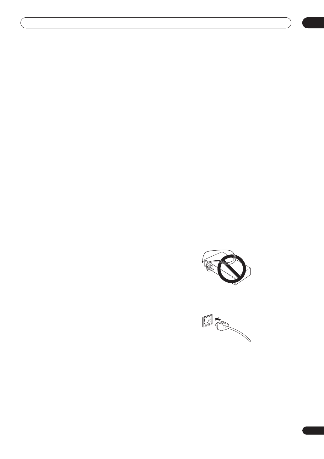
When making cable connections
Be careful not to arrange cables in a manner that bends
the cables over the top of this unit. If the cables are laid
on top of the unit, the magnetic field produced by the
transformers in this unit may cause a humming noise to
come from the speakers.
• When connecting optical cables, be careful when
inserting the plug not to damage the shutter
protecting the optical socket.
• When storing optical cable, coil loosely. The cable
may be damaged if bent around sharp corners.
13
En
Page 14
02
Connecting your equipment
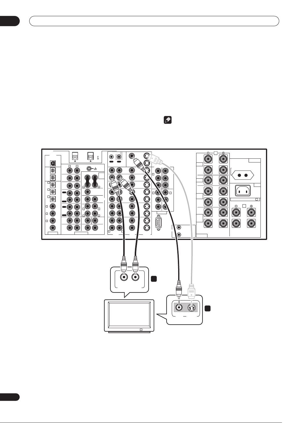
Connecting your TV
This page shows you how to connect your TV to the
amplifier. To be able to play the sound from the TV’s builtin tuner, connect the analog audio outputs from your TV
to this amplifier.
1 Connect the MONITOR OUT 1 video jack on this
amplifier to a video input on your TV.
• You can use a standard RCA/phono jack video cable
to connect to the composite video jack, or for higher
quality video, you can use an S-video cable to
connect to the S-video jack (S2 VIDEO).
• See Using the component video jacks on page 20 if
you want to use the component video outputs to
connect this amplifier to your TV.
2 Connect the analog audio outputs from your TV
to the TV/DVD AUDIO inputs on this amplifier.
• Use a stereo RCA/phono jack cable for the
connection.
Note
• If you use different cord types for the TV and the
source component, overlay information doesn’t
appear.
DIGITAL
USB AUDIO
IN
AUDIO
R L
PHONO
OUT 2
IN
CD
OUT 1
IN
6
(CD-R/
TUNER
TAPE1/
IN
MD)
IN
5
(DVR/
OUT
VCR1)
REC
IN
CD-R/
TAPE1/
4
MD
(SAT)
IN
IN
PLAY
OUT
(CD)
3 IN
REC
TAPE 2
MONITOR
(TV/
IN
2 IN
DVD)
PLAY
FRONT SUB W CENTER
(DVD/
1 IN
LD)
R
SURROUND
2RF
(DVD/
IN
LD)
RL
ASSIGNABLE MULTI CH INPUT
S400 (AUDIO)
AUDIO POWER
AMP
IN
RL
CENTER
SUB W.
1
(Single)
R L
R L
L
RL
PRE OUT
2
SURROUND
(Single)
SURROUND
BACK
(Single)
CONTROL
OUT IN
R L
MONITOR
MONITOR
DVD/
LD
IN
TV/
DVD
IN
SAT
IN
OUT
DVR/
VCR1
IN
OUT
VCR2
IN
OUT
VCR3
IN
VIDEOAUDIO S2 VIDEO
R
L
ANALOG AUDIO OUT
OUT 1
OUT 2
COMPONENT VIDEO
(DVD/
IN
LD)
IN
1
IN
IN
IN
OUT
2
IN
OUT
IN
OUT
IN
Y
P
B
PR
Y
B
P
PR
ASSIGNABLE
RS-232C
Y
MONITOR
OUT
PB
PR
IN
3
Y
PB
PR
12V TRIGGER
1
DC OUT 12V
TOTAL 100mA MAX
2
FRONT
CENTER
SURROUND
SURROUND
BACK
SPEAKERS
A
L
R
AC OUTLET
SWITCHED 100W MAX
AC IN
L
R
L
(Single)
R
SELECTABLE (SURROUND BACK & B )
B
L
R
VSA-AX10Ai
2
1
VIDEOINS-VIDEO
IN
14
En
TV
Page 15
Connecting your equipment
Connecting a DVD player
02
DIGITAL
USB AUDIO
IN
AUDIO
R L
PHONO
OUT 2
IN
CD
OUT 1
IN
6
(CD-R/
TUNER
TAPE1/
IN
MD)
IN
5
(DVR/
OUT
VCR1)
REC
IN
CD-R/
TAPE1/
4
MD
(SAT)
IN
IN
PLAY
OUT
(CD)
3 IN
REC
TAPE 2
MONITOR
(TV/
IN
2 IN
DVD)
PLAY
FRONT SUB W CENTER
(DVD/
1 IN
LD)
R
SURROUND
2RF
(DVD/
IN
LD)
RL
ASSIGNABLE MULTI CH INPUT
COAXIAL
S400 (AUDIO)
AUDIO POWER
AMP
IN
RL
CENTER
SUB W.
1
(Single)
R L
R L
L
PRE OUT
2
SURROUND
(Single)
SURROUND
BACK
(Single)
RL
CONTROL
OUT IN
R L
AUDIORL S-VIDEOOPTICAL
DVD/
LD
IN
TV/
DVD
IN
SAT
IN
OUT
DVR/
VCR1
IN
OUT
VCR2
IN
OUT
VCR3
IN
VIDEOAUDIO S2 VIDEO
MONITOR
OUT 1
MONITOR
OUT 2
OUT
OUT
OUT
IN
IN
IN
IN
IN
IN
DIGITAL OUT ANALOG OUT VIDEO OUT
1 2 3
COMPONENT VIDEO
(DVD/
LD)
IN
Y
1
P
B
PR
IN
2
Y
B
P
PR
ASSIGNABLE
RS-232C
Y
MONITOR
OUT
PB
PR
IN
3
Y
PB
PR
12V TRIGGER
1
DC OUT 12V
TOTAL 100mA MAX
2
FRONT
CENTER
SURROUND
SURROUND
BACK
SPEAKERS
A
L
R
SWITCHED 100W MAX
AC OUTLET
AC IN
L
R
L
(Single)
R
SELECTABLE (SURROUND BACK & B )
B
L
R
VSA-AX10Ai
DVD player
Different DVD players offer a different selection of
connections, but all should give you at least a digital
audio output, stereo analog audio outputs and a video
output. Additionally, you may have a player with
multichannel analog audio outputs and different kinds of
video outputs to choose from.
1 Connect a coaxial digital audio output on your
DVD player to the DIGITAL 1 (DVD/LD) input on this
amplifier.
• Use a coaxial cable designed for digital audio for the
connection.
• If your DVD player only has an optical digital output,
you can connect it to one of the optical inputs on this
amplifier using an optical cable. When you set up the
amplifier you’ll need to tell the amplifier which input
you connected the player to (see also Assigning the
digital inputs on page 83).
2 If your DVD player only has stereo analog audio
outputs, connect these to the DVD/LD AUDIO inputs
on this amplifier.
• Use standard RCA/phono jack cables for the
connections.
• If your DVD player has multichannel analog outputs,
see Connecting the multichannel analog outputs
below for how to connect it.
3 Connect a composite or S-video output on your
DVD player to the DVD/LD VIDEO or DVD/LD S2
VIDEO input on this amplifier.
• Use a standard video cable or an S-video cable for the
connection.
• If your player also has a component video output, you
can connect this too. See Using the component video
jacks on page 20 for more on this.
15
En
Page 16
02
Connecting your equipment
Connecting the multichannel analog outputs
DIGITAL
USB AUDIO
IN
AUDIO
R L
PHONO
OUT 2
IN
CD
OUT 1
IN
6
(CD-R/
TUNER
TAPE1/
IN
MD)
IN
5
(DVR/
OUT
VCR1)
REC
IN
CD-R/
TAPE1/
4
MD
(SAT)
IN
IN
PLAY
OUT
(CD)
3 IN
REC
TAPE 2
MONITOR
(TV/
IN
2 IN
DVD)
PLAY
FRONT SUB W CENTER
(DVD/
1 IN
LD)
R L
SURROUND
2RF
(DVD/
IN
LD)
RL
ASSIGNABLE MULTI CH INPUT
RL
FRONT SUB W. CENTER
S400 (AUDIO)
AUDIO POWER
AMP
IN
RL
CENTER
SUB W.
1
(Single)
PRE OUT
2
SURROUND
R L
R L
(Single)
SUR-
ROUND
BACK
(Single)
RL
CONTROL
OUT IN
R L
DVD/
LD
IN
TV/
DVD
IN
SAT
IN
OUT
DVR/
VCR1
IN
OUT
VCR2
IN
OUT
VCR3
IN
VIDEOAUDIO S2 VIDEO
MONITOR
OUT 1
MONITOR
OUT 2
A
L
1
DC OUT 12V
TOTAL 100mA MAX
2
FRONT
CENTER
SURROUND
SURROUND
BACK
SPEAKERS
R
L
R
L
R
SELECTABLE (SURROUND BACK & B )
(Single)
COMPONENT VIDEO
(DVD/
IN
LD)
IN
IN
IN
OUT
IN
OUT
IN
OUT
IN
1
IN
2
Y
P
PR
Y
P
PR
B
B
ASSIGNABLE
RS-232C
Y
MONITOR
OUT
PB
PR
IN
3
Y
PB
PR
12V TRIGGER
AC OUTLET
SWITCHED 100W MAX
AC IN
B
L
R
VSA-AX10Ai
16
En
RL
SURR.
MULTI CH
OUTPUT
RL
SURR.
BACK
MULTI CH. OUT
1 2
DVD player
For DVD Audio and SACD playback, your DVD player may
have 5.1, 6.1 or 7.1 channel analog outputs (depending
on whether your player supports surround back
channels).
1 Connect the front, surround, center and
subwoofer outputs on your DVD player to the
corresponding MULTI CH INPUT jack on this
amplifier.
• Use standard RCA/phono jack cables for the
connections.
• Take care to connect each output to its
corresponding input on the amplifier.
2 If your DVD player also has outputs for surround
back channels, connect these to the corresponding
MULTI CH INPUT jacks on this amplifier.
• Use standard RCA/phono jack cables for the
connections.
• If there is a single surround back output, connect it to
the SURROUND BACK L (SINGLE) jack on this
amplifier.
Note
• To listen to multichannel analog audio you’ll need to
switch the input signal selector to MULTI CH INPUT
(see Playing a source on page 37 for more on this).
See also Selecting USB and multichannel analog input
channels on page 45.
Page 17
Connecting your equipment
Connecting a satellite/cable amplifier or other set-top box
Satellite and cable amplifiers, and terrestrial digital TV
tuners are all examples of so-called ‘set-top boxes’.
1 Connect a set of audio/video outputs on the settop box component to the SAT AUDIO and VIDEO
inputs on this amplifier.
• Use a stereo RCA/phono jack audio cable for the
audio connection and a video or S-video cable for the
video connection.
2 Connect an optical digital audio output from
your set-top box component to the DIGITAL 4 (SAT)
input on this amplifier.
• Use an optical cable for the connection.
• If your set-top box only has a coaxial digital output,
you can connect it to one of the coaxial inputs on this
amplifier using a coaxial digital audio cable. When
you set up the amplifier you’ll need to tell the
amplifier which input you connected the set-top box
to (see also Assigning the digital inputs on page 83).
Note
• If your satellite/cable amplifier doesn’t have a digital
audio output, omit step 2 above.
02
DIGITAL
USB AUDIO
IN
AUDIO
R L
PHONO
OUT 2
IN
CD
OUT 1
IN
6
(CD-R/
TUNER
TAPE1/
IN
MD)
IN
5
(DVR/
OUT
VCR1)
REC
IN
CD-R/
TAPE1/
4
MD
(SAT)
IN
IN
PLAY
OUT
(CD)
3 IN
REC
TAPE 2
MONITOR
(TV/
IN
2 IN
DVD)
PLAY
FRONT SUB W CENTER
(DVD/
1 IN
LD)
R
SUR-
ROUND
2RF
(DVD/
IN
LD)
ASSIGNABLE MULTI CH INPUT
RL
S400 (AUDIO)
AUDIO POWER
AMP
IN
RL
CENTER
SUB W.
1
(Single)
R L
R L
L
PRE OUT
2
SURROUND
(Single)
SURROUND
BACK
(Single)
RL
DIGITAL OUT
CONTROL
OUT IN
R L
DVD/
LD
IN
TV/
DVD
IN
SAT
IN
OUT
DVR/
VCR1
IN
OUT
VCR2
IN
OUT
VCR3
IN
VIDEOAUDIO S2 VIDEO
R
MONITOR
OUT 1
MONITOR
OUT 2
OUT
OUT
OUT
A
L
1
DC OUT 12V
TOTAL 100mA MAX
2
FRONT
CENTER
SURROUND
SURROUND
BACK
SPEAKERS
R
L
R
L
(Single)
R
SWITCHED 100W MAX
SELECTABLE (SURROUND BACK & B )
COMPONENT VIDEO
(DVD/
IN
LD)
IN
IN
IN
IN
IN
IN
1
IN
2
Y
P
B
PR
Y
B
P
PR
ASSIGNABLE
RS-232C
Y
MONITOR
OUT
PB
PR
IN
3
Y
PB
PR
12V TRIGGER
AC OUTLET
AC IN
B
L
R
VSA-AX10Ai
VIDEO S-VIDEOAUDIOL
AV OUT
STB
17
En
Page 18
02
Connecting your equipment
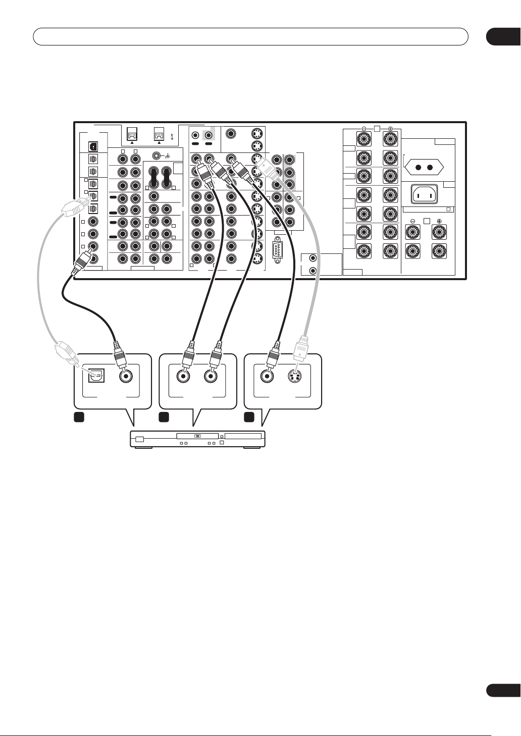
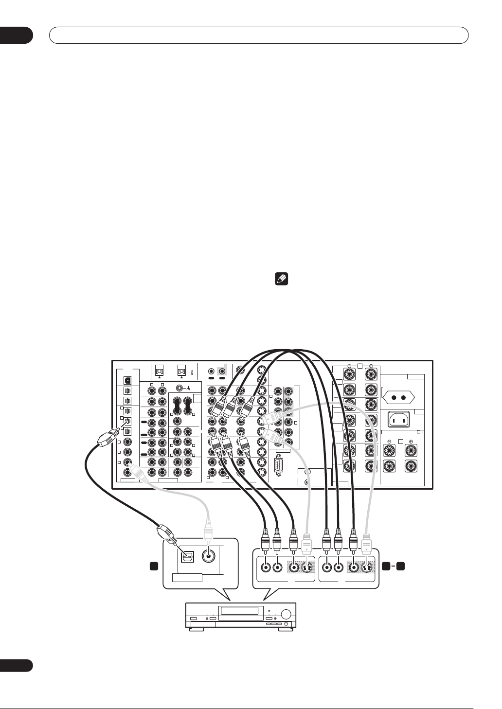
Connecting a VCR or DVD recorder
This amplifier has three sets of audio/video inputs and
outputs suitable for connecting analog or digital video
recorders, including VCRs, DVD-recorders and HDD
recorders.
1 Connect a set of audio/video outputs on the
recorder to the DVR/VCR1 AUDIO and VIDEO inputs
on this amplifier.
• Use a stereo RCA/phono jack audio cable for the
audio connection and a video or S-video cable for the
video connection.
• For a second and third recorder, use the VCR2 IN and
VCR3 IN inputs.
2 Connect a set of audio/video inputs on the
recorder to the DVR/VCR1 AUDIO and VIDEO outputs
on this amplifier.
• Use a stereo RCA/phono jack audio cable for the
audio connection and a video or S-video cable for the
video connection.
• For a second and third recorder, use the VCR2 and
VCR3 outputs.
3 Connect an optical digital audio output from the
recorder to the DIGITAL 5 (DVR/VCR1) input on this
amplifier.
• Use an optical cable for the connection.
• If your recorder only has a coaxial digital output, you
can connect it to one of the coaxial inputs on this
amplifier using a coaxial digital audio cable. When
you set up the amplifier you’ll need to tell the
amplifier which input you connected the recorder to
(see also Assigning the digital inputs on page 83).
• The digital outputs from other recorders can be
connected to any spare digital audio inputs on this
amplifier. You can assign them when setting up the
amplifier (see also Assigning the digital inputs on
page 83).
Note
• If your video component doesn’t have a digital audio
output, omit step 3 above.
• In order to record, you must connect the analog
audio cables (the digital connection is for playback
only).
DIGITAL
USB AUDIO
IN
AUDIO
R L
PHONO
OUT 2
IN
CD
OUT 1
IN
6
(CD-R/
TUNER
TAPE1/
IN
MD)
IN
5
(DVR/
OUT
VCR1)
REC
IN
CD-R/
TAPE1/
4
MD
(SAT)
IN
IN
PLAY
OUT
(CD)
3 IN
REC
TAPE 2
MONITOR
(TV/
IN
2 IN
DVD)
PLAY
FRONT SUB W CENTER
(DVD/
1 IN
LD)
R
SURROUND
2RF
(DVD/
IN
LD)
RL
ASSIGNABLE MULTI CH INPUT
S400 (AUDIO)
AUDIO POWER
AMP
IN
RL
CENTER
SUB W.
PRE OUT
1
2
(Single)
SURROUND
R L
R L
(Single)
L
SURROUND
BACK
RL
(Single)
OPTICAL COAXIAL
DIGITAL OUT
CONTROL
OUT IN
R L
DVD/
LD
IN
TV/
DVD
IN
SAT
IN
OUT
DVR/
VCR1
IN
OUT
VCR2
IN
OUT
VCR3
IN
VIDEOAUDIO S2 VIDEO
MONITOR
MONITOR
VSA-AX10Ai
FRONT
CENTER
SURROUND
SURROUND
BACK
SPEAKERS
A
L
R
AC OUTLET
SWITCHED 100W MAX
AC IN
L
(Single)
SELECTABLE (SURROUND BACK & B )
B
L
R
1 23
R
L
R
VIDEO S-VIDEO
AV IN
OUT 1
OUT 2
COMPONENT VIDEO
(DVD/
IN
LD)
Y
IN
Y
1
MONITOR
IN
IN
OUT
IN
OUT
IN
OUT
IN
OUT
PB
B
P
PR
PR
IN
IN
3
2
Y
Y
PB
B
P
PR
PR
ASSIGNABLE
1
DC OUT 12V
12V TRIGGER
RS-232C
TOTAL 100mA MAX
2
VIDEOAUDIOLR
S-VIDEO AUDIOLR
AV OUT
18
En
DVR, VCR, etc.
Page 19
Connecting your equipment
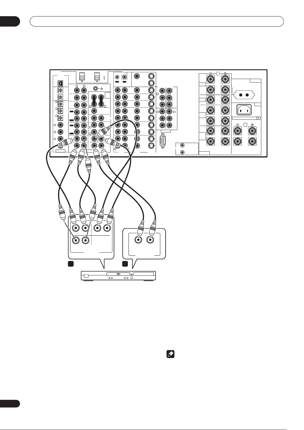
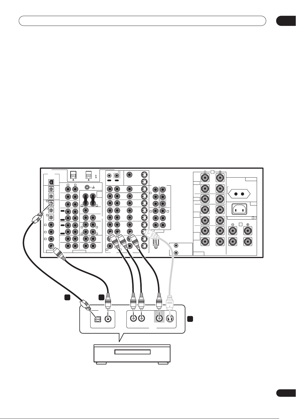
Connecting other video sources
You can basically use any of the audio/video inputs on
this amplifier for any kind of video source. The example
illustration below shows a component connected to the
VCR2 inputs.
1 Connect the analog audio outputs and a video
output of the source component to a set of spare
audio/video inputs on this amplifier.
• Use a stereo RCA/phono jack audio cable for the
audio connection and a video or S-video cable for the
video connection.
2 If the source component has a digital audio
output, connect it to a spare digital audio input on
this amplifier.
• Use a coaxial cable designed for digital audio or an
optical cable for the connection depending on the
type of input you used.
02
• You may need to assign the digital input you used
when setting up the amplifier (see also Assigning the
digital inputs on page 83).
3 If the source component is an LD player with a
2 RF digital audio output, connect this to the 2 RF
input on this amplifier.
To ensure compatibility with all laserdiscs, connect both
the PCM and 2 RF outputs from your LD player.
• Use a coaxial cable designed for digital audio for the
2 RF connection.
• You may need to assign the 2 RF digital input when
setting up the amplifier (see also Assigning the digital
inputs on page 83).
DIGITAL
USB AUDIO
IN
AUDIO
R L
PHONO
OUT 2
IN
CD
OUT 1
IN
6
(CD-R/
TUNER
TAPE1/
IN
MD)
IN
5
(DVR/
OUT
VCR1)
REC
IN
CD-R/
TAPE1/
4
MD
(SAT)
IN
IN
PLAY
OUT
(CD)
3 IN
REC
TAPE 2
MONITOR
(TV/
IN
2 IN
DVD)
PLAY
FRONT SUB W CENTER
(DVD/
1 IN
LD)
R
SURROUND
2RF
(DVD/
IN
LD)
ASSIGNABLE MULTI CH INPUT
RL
2 3
S400 (AUDIO)
AUDIO POWER
AMP
IN
RL
CENTER
SUB W.
1
(Single)
R L
R L
L
PRE OUT
2
SURROUND
(Single)
SURROUND
BACK
(Single)
RL
DIGITAL OUT
PCM 2 RF
CONTROL
OUT IN
R L
DVD/
LD
IN
TV/
DVD
IN
SAT
IN
OUT
DVR/
VCR1
IN
OUT
VCR2
IN
OUT
VCR3
IN
VIDEOAUDIO S2 VIDEO
MONITOR
MONITOR
L
OUT 1
OUT 2
COMPONENT VIDEO
(DVD/
IN
LD)
IN
1
IN
IN
IN
OUT
2
IN
OUT
IN
OUT
IN
Y
P
B
PR
Y
B
P
PR
ASSIGNABLE
RS-232C
Y
MONITOR
OUT
PB
PR
IN
3
Y
PB
PR
12V TRIGGER
1
DC OUT 12V
TOTAL 100mA MAX
2
FRONT
CENTER
SURROUND
SURROUND
BACK
SPEAKERS
A
L
R
SWITCHED 100W MAX
AC OUTLET
AC IN
L
R
L
(Single)
R
SELECTABLE (SURROUND BACK & B )
B
L
R
VSA-AX10Ai
R
VIDEO S-VIDEOAUDIO
AV OUT
1
LD player, video player, TV game, etc.
19
En
Page 20
02
Connecting your equipment
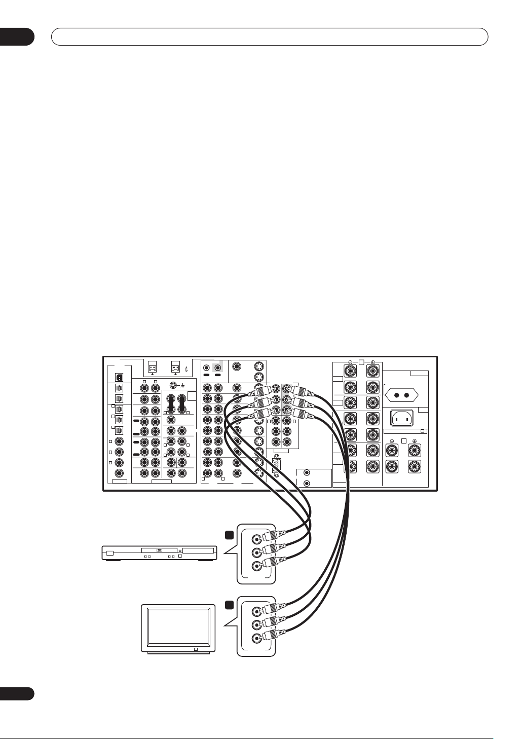
Using the component video jacks
Component video should deliver superior picture quality
when compared to composite or S-video. A further
advantage (if your source and TV are both compatible) is
progressive-scan video, which delivers a very stable,
flicker-free picture. See the manuals that came with your
TV and source component to check whether they are
compatible with progressive-scan video. Note that it is
not possible to see overlay information when you have
connected using component video cables.
1 Connect the component video outputs of your
source to a set of component video inputs on this
amplifier.
There are three component video inputs; they are all
freely assignable so that they can be used in conjunction
with any of the audio/video input functions of the
amplifier.
Note that you’ll need to assign the component video
input (see Assigning the component video inputs on
page 84), or else you may see the S-video or composite
video input instead.
• Use a three-way component video cable for the
connection.
2 Connect the COMPONENT VIDEO MONITOR OUT
jacks on this amplifier to the component video
inputs on your TV or monitor.
• Use a three-way component video cable.
About the video converter
The video converter allows you to connect various video
sources using composite, S-video or component video
connections and the signal will be output through all of
the MONITOR VIDEO OUT jacks. The only exception is
component video input, which is only output from the
component video output. Therefore, if you want to
connect any source using component video, you must
also connect your TV using component video. If several
video components are connected to the same input
function, the converter gives priority to component, Svideo, then composite (in that order).
• You can’t see overlay information if you use different
cord types for the TV and the source component.
• NTSC sources are not converted except from S-video
to component video (not vice-versa).
DIGITAL
USB AUDIO
IN
PHONO
OUT 2
IN
CD
OUT 1
IN
6
(CD-R/
TUNER
TAPE1/
IN
MD)
IN
5
(DVR/
OUT
VCR1)
REC
IN
CD-R/
TAPE1/
4
MD
(SAT)
IN
IN
PLAY
OUT
(CD)
3 IN
REC
TAPE 2
MONITOR
(TV/
IN
2 IN
DVD)
PLAY
FRONT SUB W CENTER
(DVD/
1 IN
LD)
R
SURROUND
2RF
(DVD/
IN
LD)
RL
ASSIGNABLE MULTI CH INPUT
DVD player
R L
TV
AUDIO
S400 (AUDIO)
AUDIO POWER
AMP
IN
RL
CENTER
SUB W.
PRE OUT
1
2
(Single)
SURROUND
R L
R L
(Single)
L
SURROUND
BACK
RL
(Single)
CONTROL
OUT IN
R L
DVD/
LD
IN
TV/
DVD
IN
SAT
IN
OUT
DVR/
VCR1
IN
OUT
VCR2
IN
OUT
VCR3
IN
VIDEOAUDIO S2 VIDEO
1
2
MONITOR
MONITOR
OUT 1
OUT 2
IN
IN
IN
OUT
IN
OUT
IN
OUT
IN
Y
PB
PR
COMPONENT
Y
P
B
PR
COMPONENT
A
COMPONENT VIDEO
(DVD/
LD)
IN
Y
1
B
P
PR
IN
2
Y
B
P
PR
ASSIGNABLE
RS-232C
Y
MONITOR
OUT
PB
PR
IN
3
Y
PB
PR
12V TRIGGER
1
DC OUT 12V
TOTAL 100mA MAX
2
FRONT
CENTER
SURROUND
SURROUND
BACK
SPEAKERS
L
R
L
R
L
(Single)
R
AC OUTLET
SWITCHED 100W MAX
AC IN
SELECTABLE (SURROUND BACK & B )
B
L
R
VSA-AX10Ai
VIDEO
VIDEO
20
En
Page 21
Connecting your equipment
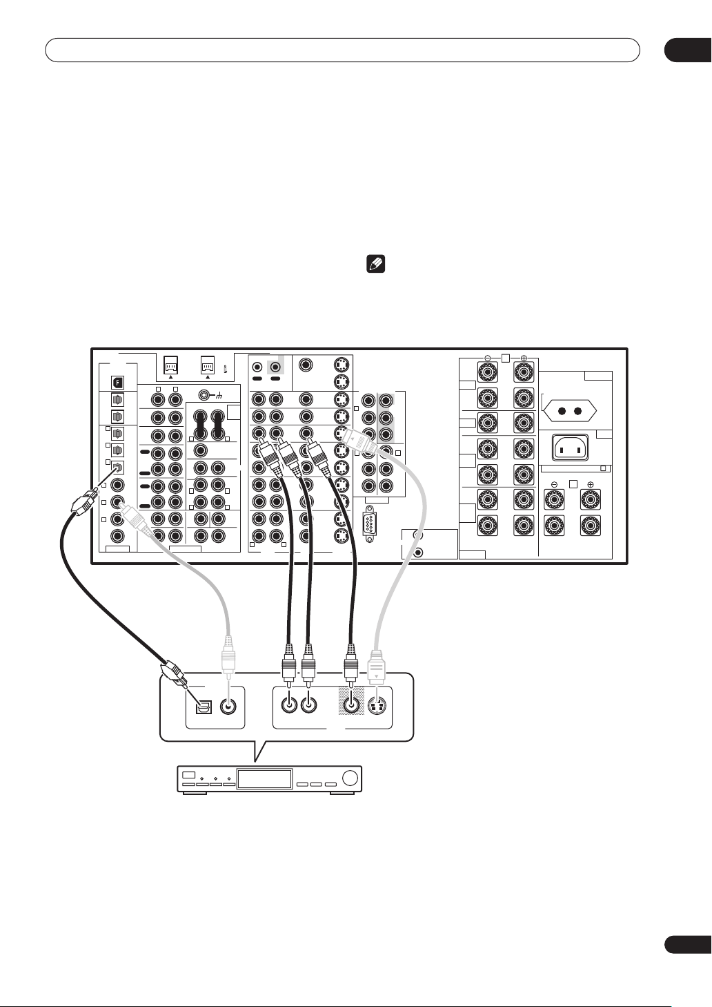
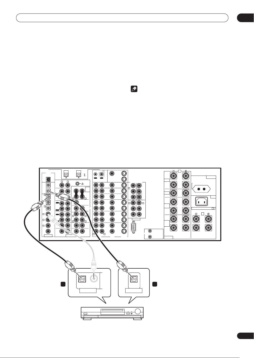
Connecting digital audio sources
This amplifier has both digital inputs and outputs,
allowing you to connect digital components for playback
and for making digital recordings. Many digital
components also have analog connections for recording
analog sources (such as a turntable or tape deck). See
Connecting analog audio sources below for more on this.
1 Connect an optical digital audio output on your
digital component to the DIGITAL 6 (CD-R/TAPE1/
MD) input on this amplifier.
• Use an optical cable for the connection.
• If your digital component only has a coaxial digital
output, you can connect it to one of the coaxial inputs
on this amplifier using a coaxial cable. When you set
up the amplifier you’ll need to tell the amplifier which
input you connected the component to (see also
Assigning the digital inputs on page 83).
• The digital outputs from other components can be
connected to any spare digital audio inputs on this
amplifier. You can assign them when setting up the
amplifier (see also Assigning the digital inputs on
page 83).
02
2 Connect one of the DIGITAL outputs on this
amplifier to a digital input on the component.
• Use an optical cable to connect to the DIGITAL
OUT1 or OUT2 (OUT1 is shown in the illustration
below).
Note
• In order to record some digital sources, you must
make analog connections as explained in Connecting
analog audio sources below.
• This unit has an on-board WMA9 Pro decoder, so it is
possible to playback WMA9 Pro-encoded audio using
a coaxial or optical digital connection when
connected to a WMA9 Pro-compatible player.
However, the connected PC, DVD player, set-top box,
etc. must be able to output WMA9 Pro format audio
signals through a coaxial or optical digital output.
DIGITAL
USB AUDIO
IN
AUDIO
R L
PHONO
OUT 2
IN
CD
OUT 1
IN
6
(CD-R/
TUNER
TAPE1/
IN
MD)
IN
5
(DVR/
OUT
VCR1)
REC
IN
CD-R/
TAPE1/
4
MD
(SAT)
IN
IN
PLAY
OUT
(CD)
3 IN
REC
TAPE 2
MONITOR
(TV/
IN
2 IN
DVD)
PLAY
FRONT SUB W CENTER
(DVD/
1 IN
LD)
R
SURROUND
2RF
(DVD/
IN
LD)
RL
ASSIGNABLE MULTI CH INPUT
1 2
S400 (AUDIO)
AUDIO POWER
AMP
IN
RL
CENTER
SUB W.
1
(Single)
L
PRE OUT
2
SURROUND
R L
R L
(Single)
SURROUND
BACK
(Single)
RL
OPTICAL COAXIAL
DIGITAL OUT
CONTROL
OUT IN
R L
DVD/
LD
IN
TV/
DVD
IN
SAT
IN
OUT
DVR/
VCR1
IN
OUT
VCR2
IN
OUT
VCR3
IN
VIDEOAUDIO S2 VIDEO
MONITOR
MONITOR
FRONT
CENTER
SURROUND
SURROUND
BACK
SPEAKERS
A
L
R
AC OUTLET
SWITCHED 100W MAX
AC IN
L
(Single)
SELECTABLE (SURROUND BACK & B )
B
L
R
R
L
R
OUT 1
OUT 2
COMPONENT VIDEO
(DVD/
IN
LD)
IN
IN
IN
OUT
IN
OUT
IN
OUT
IN
Y
Y
1
MONITOR
OUT
PB
P
B
PR
PR
IN
IN
3
2
Y
Y
PB
B
P
PR
PR
ASSIGNABLE
1
DC OUT 12V
12V TRIGGER
RS-232C
TOTAL 100mA MAX
2
VSA-AX10Ai
OPTICAL
DIGITAL IN
CD-R, MD, DAT, etc.
21
En
Page 22
02
Connecting your equipment
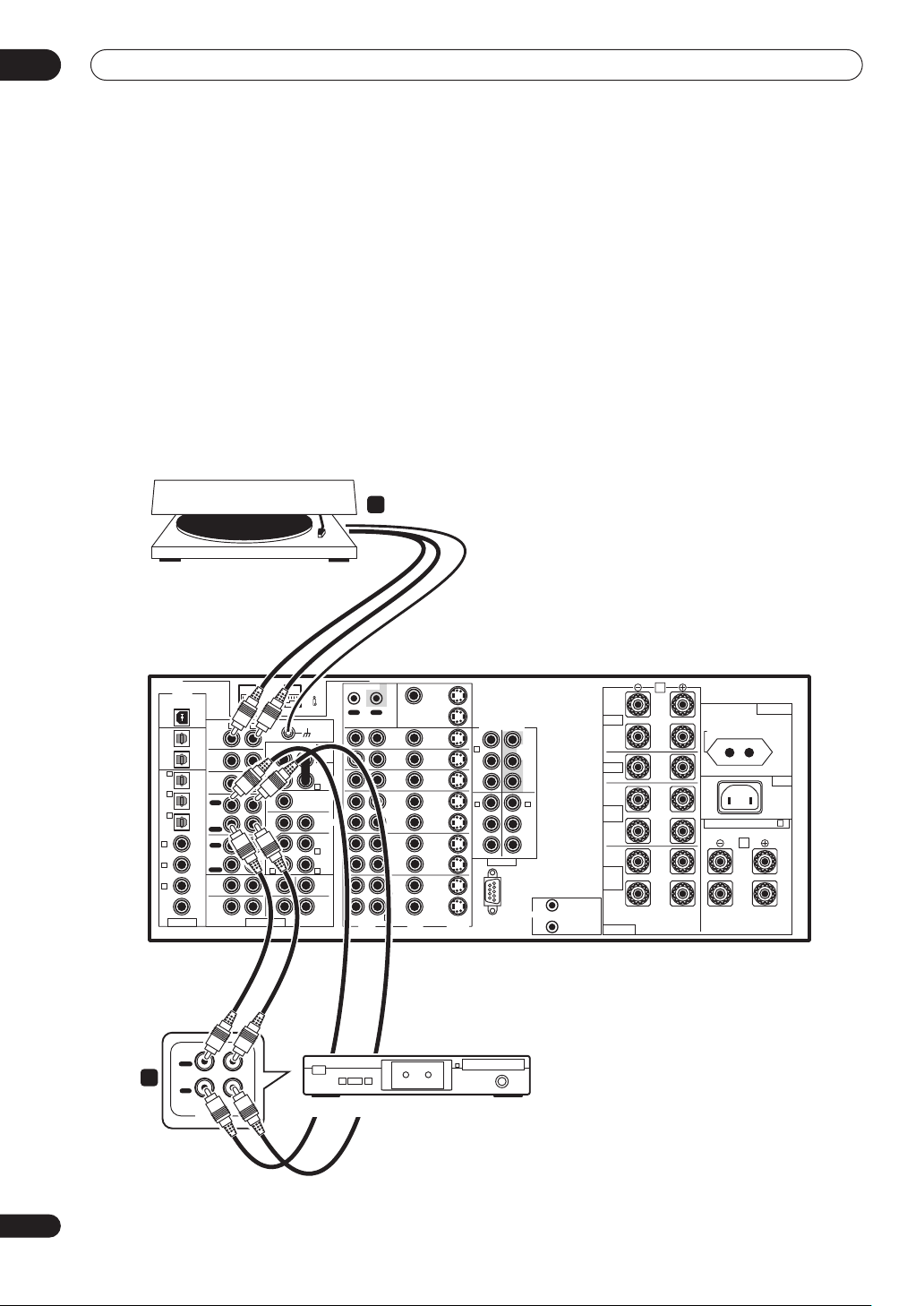
Connecting analog audio sources
This amplifier features five stereo analog inputs for audio
sourses such as a CD player, tape deck, turntable, or a
radio tuner. Two of these inputs have corresponding
outputs for use with audio recorders.
One of the audio inputs (PHONO) is a dedicated
turntable input which should not be used for any other
type of component. This input also has a grounding
terminal that most turntables require.
1 Connect the analog audio outputs of the source
component to a set of spare audio inputs on this
amplifier.
• If you’re connecting a tape deck, MD recorder, etc.,
connect the analog audio outputs (REC) to the analog
audio inputs on the recorder.
1
Turntable
• Use a stereo RCA/phono jack audio cable for the
connections.
• If your cassette deck has a monitoring function,
connect it to the TAPE 2 MONITOR jacks on the rear
panel. See Monitoring your recording on page 69 for
more on this.
2 Turntables only: Connect the stereo audio outputs
to the PHONO inputs on this amplifier.
• If your turntable has a grounding wire, secure it to the
ground terminal on this amplifier.
• If your turntable has line-level outputs (no grounding
wire), connect them to the CD inputs instead.
DIGITAL
USB AUDIO
IN
PHONO
OUT 2
IN
CD
OUT 1
IN
6
(CD-R/
TUNER
TAPE1/
IN
MD)
IN
5
(DVR/
OUT
VCR1)
REC
IN
CD-R/
TAPE1/
4
MD
(SAT)
IN
IN
PLAY
OUT
(CD)
3 IN
REC
TAPE 2
MONITOR
(TV/
IN
2 IN
DVD)
PLAY
FRONT SUB W CENTER
(DVD/
1 IN
LD)
R
SURROUND
2RF
(DVD/
IN
LD)
RL
ASSIGNABLE MULTI CH INPUT
OUT
PLAY
2
IN
REC
RL
AUDIO IN/OUT
AUDIO
R L
L
S400 (AUDIO)
AUDIO POWER
AMP
IN
RL
CENTER
SUB W.
1
(Single)
PRE OUT
2
SURROUND
R L
R L
(Single)
SURROUND
BACK
(Single)
RL
Tape deck, etc.
CONTROL
OUT IN
R L
DVD/
LD
IN
TV/
DVD
IN
SAT
IN
OUT
DVR/
VCR1
IN
OUT
VCR2
IN
OUT
VCR3
IN
VIDEOAUDIO S2 VIDEO
MONITOR
OUT 1
MONITOR
OUT 2
A
L
1
DC OUT 12V
TOTAL 100mA MAX
2
FRONT
CENTER
SURROUND
SURROUND
BACK
SPEAKERS
R
L
R
L
R
SELECTABLE (SURROUND BACK & B )
(Single)
COMPONENT VIDEO
(DVD/
IN
LD)
IN
IN
IN
OUT
IN
OUT
IN
OUT
IN
Y
Y
1
MONITOR
OUT
PB
P
B
PR
PR
IN
IN
3
2
Y
Y
PB
B
P
PR
PR
ASSIGNABLE
12V TRIGGER
RS-232C
AC OUTLET
SWITCHED 100W MAX
AC IN
B
L
R
VSA-AX10Ai
22
En
Page 23
Connecting your equipment
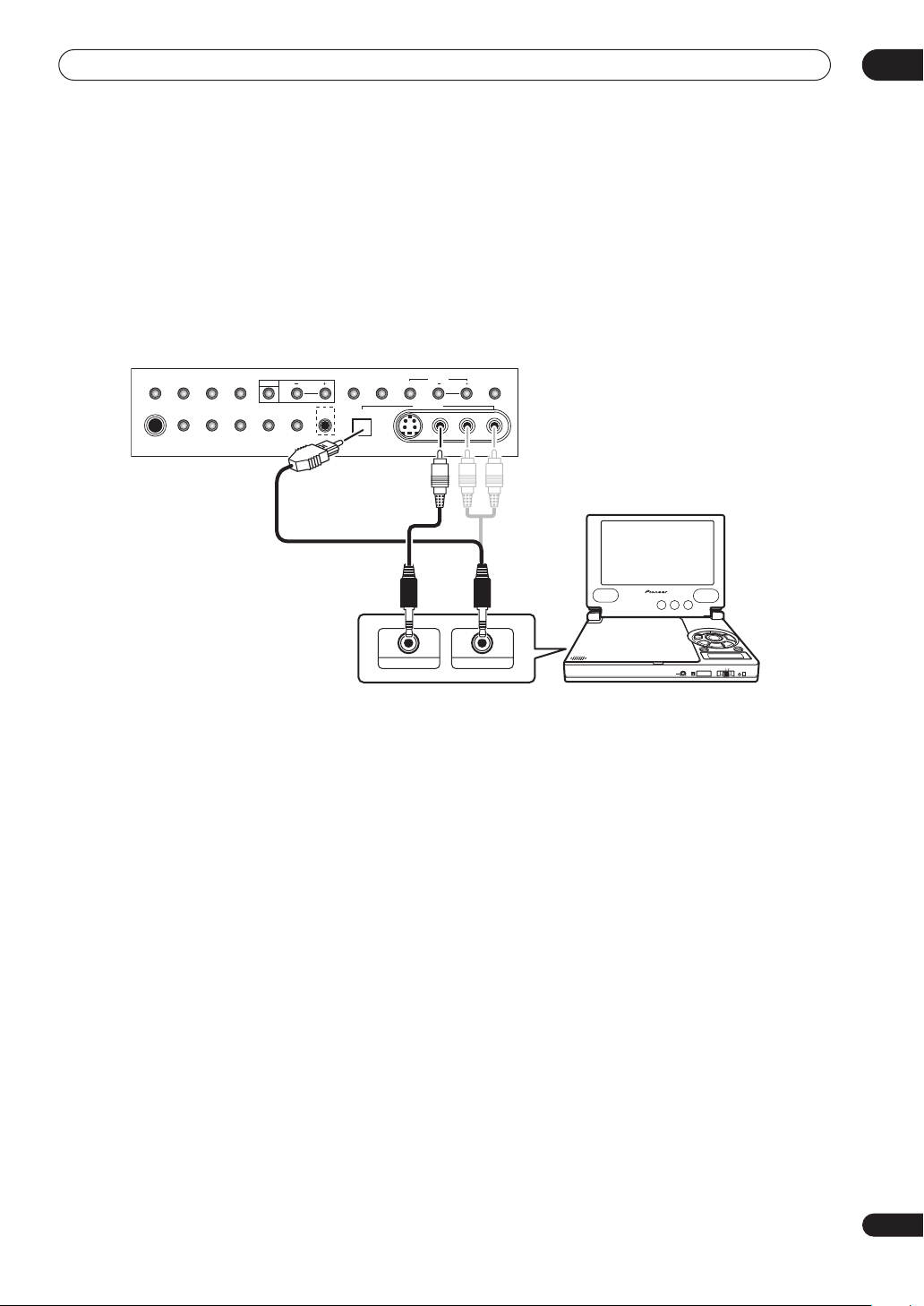
Connecting a component to the front panel inputs
The front panel inputs include a composite video jack
(VIDEO), an S-video jack (S-VIDEO), stereo analog audio
inputs (AUDIO L/R) and an optical digital audio input
(DIGITAL). You can use these connections for any kind of
audio/video component, but they are especially
convenient for portable equipment such as camcorders,
video games and portable audio/video equipment.
• The input signals can be accessed by selecting
VIDEO using the INPUT SELECTOR dial on the front
panel.
• Pull down the front cover where indicated to access
the front panel inputs.
• The illustration below shows example connections to
a portable DVD player. Note that you may need a
specialized optical cable for this connection.
02
ACOUSTIC
PHONES
LOUDNESS OPTIONTONE DIGITAL NR INPUT ATT
CAL.
MIDNIGHT
SP SYSTEM
A/B
VSA-AX10Ai
CH LEVEL
SELECT
SIGNAL
VIDEO
TAPE2
STREAM
SETUP
SELECT
SELECT
MONITOR
DIRECT
DIGITAL IN
MIC
VIDEO INPUT
S-VIDEO VIDEO
VIDEO IN/OUT
SB CH
MODE
AUDIOLR
AUDIO IN/OUT
DIGITAL OUT (OPTICAL)
COLOR BRIGHT MONITOR
PHONES
HOLDON/OFF
Portable DVD player, etc.
23
En
Page 24
02
Connecting your equipment
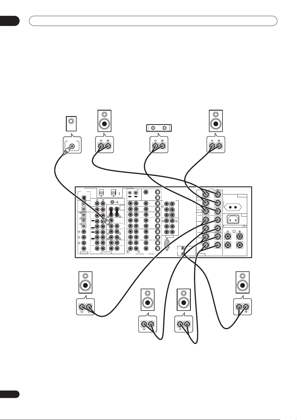
Installing your speaker system
To take full advantage of the amplifier’s surround sound
capabilities connect front, center, surround and
surround back speakers, as well as a subwoofer.
Although this is ideal, other configurations with fewer
speakers—no subwoofer or no center speaker, or even
no surround speakers—will work. At the very least, front
left and right speakers only are necessary. Note that your
main surround speakers should always be connected as
a pair, but you can connect just one surround back
speaker if you like (it must be connected to the left
surround back terminal). You can use speakers with a
nominal impedance between 4–16Ω (please see
Switching the speaker impedance on page 72 if you plan
to use speakers with an impedance of less than 6Ω).
Subwoofer
LINE LEVEL
INPUT
VSA-AX10Ai
DIGITAL
USB AUDIO
IN
AUDIO
R L
PHONO
OUT 2
IN
CD
OUT 1
IN
6
(CD-R/
TUNER
TAPE1/
IN
MD)
IN
5
(DVR/
OUT
VCR1)
REC
IN
CD-R/
TAPE1/
4
MD
(SAT)
IN
IN
PLAY
OUT
(CD)
3 IN
REC
TAPE 2
MONITOR
(TV/
IN
2 IN
DVD)
PLAY
FRONT SUB W CENTER
(DVD/
1 IN
LD)
R
SURROUND
2RF
(DVD/
IN
LD)
RL
ASSIGNABLE MULTI CH INPUT
Surround
left
Front
left
S400 (AUDIO)
AUDIO POWER
AMP
IN
RL
CENTER
SUB W.
PRE OUT
1
2
(Single)
SURROUND
R L
R L
(Single)
L
SURROUND
BACK
RL
(Single)
CONTROL
OUT IN
R L
Center
MONITOR
OUT 1
MONITOR
OUT 2
DVD/
IN
LD
IN
TV/
IN
DVD
IN
SAT
IN
IN
OUT
OUT
DVR/
VCR1
IN
IN
OUT
OUT
VCR2
IN
IN
OUT
OUT
VCR3
IN
IN
VIDEOAUDIO S2 VIDEO
Surround
back left
COMPONENT VIDEO
(DVD/
LD)
IN
Y
1
B
P
PR
IN
2
Y
P
B
PR
ASSIGNABLE
RS-232C
Y
MONITOR
OUT
PB
PR
IN
3
Y
PB
PR
1
12V TRIGGER
TOTAL 100mA MAX
2
Surround
back right
DC OUT 12V
Front
right
FRONT
CENTER
SURROUND
SURROUND
BACK
SPEAKERS
A
L
R
AC OUTLET
SWITCHED 100W MAX
AC IN
L
(Single)
SELECTABLE (SURROUND BACK & B )
B
L
R
R
L
R
Surround
right
24
En
Connecting the speakers
Each speaker connection on the amplifier comprises a
positive (+) red, and negative (–) white terminal. For
proper sound you should take care to match these up
with the terminals on the speakers themselves.
Page 25
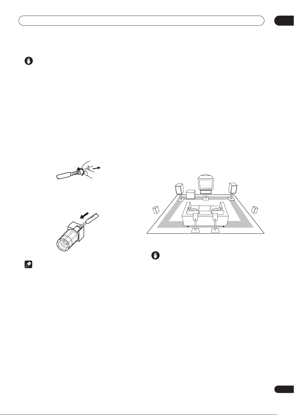
Connecting your equipment
02
Caution
• These speaker terminals can be under hazardous
voltage. When you connect or disconnect the speaker
cables, to prevent the risk of electric shock, do not
touch uninsulated parts before disconnecting the
power cord.
• Make sure that all the bare speaker wire is twisted
together and inserted fully into the speaker terminal.
If any of the bare speaker wire touches the back panel
it may cause the power to cut off as a safety measure.
Bare wire connections
Before you start connecting the speakers, make sure that
the speaker cable you’re going to use is properly
prepared with about 1 cm of insulator stripped from each
wire, and the exposed wire strands twisted together.
To connect a terminal, unscrew the terminal a few turns
until there is enough space to insert the exposed wire.
Once the wire is in position, tighten the terminal until the
wire is firmly clamped.
• The subwoofer can be placed on the floor. Ideally, the
other speakers should be at about ear-level when
you’re listening to them. Putting the speakers on the
floor (except the subwoofer), or mounting them very
high on a wall is not recommended.
• For the best stereo effect, place the front speakers
2–2.5 m apart, at equal distance from the TV.
• Install the center speaker above or below the TV so
that the sound of the center channel is localized at
the TV screen.
• When placing speakers near the TV, use magnetically
shielded speakers to prevent possible interference,
such as discoloration of the picture when the TV is
switched on. If you do not have magnetically shielded
speakers and notice discoloration of the TV picture,
move the speakers farther away from the TV.
• If possible, install the surround speakers slightly
above ear level.
Center
Front R
Surround
R
Surround
L
Front L
Subwoofer
Note
• Please refer to the manual that came with your
speakers for details on how to connect the other end
of the speaker cables to your speakers.
• The speaker terminals on this amplifier can be
connected in a number of ways, depending on your
setup. See Speaker Systems on page 52 for an
overview of the possible configurations.
• Other connections on page 75 provides greater detail
on alternate speaker setups such as using speaker
system B (page 75), bi-surround (page 77), bi-amping
(page 76) and bi-wiring (page 77).
Placing the speakers
Where you put your speakers in the room has a big effect
on the quality of the sound. The following guidelines
should help you to get the best sound from your system.
(see also Optimizing your speaker setup on page 90).
Surround
back L
Surround
back R
Caution
• Make sure that all speakers are securely installed.
This not only improves sound quality, but also
reduces the risk of damage or injury resulting from
speakers being knocked over or falling in the event of
external shocks such as earthquakes.
25
En
Page 26

02
Connecting your equipment
Plugging in the amplifier
Only plug in after you have connected all your
components to this amplifier, including the speakers.
Caution
• Handle the power cord by the plug part. Do not pull
out the plug by tugging the cord, and never touch the
power cord when your hands are wet, as this could
cause a short circuit or electric shock. Do not place
the unit, a piece of furniture, or other object on the
power cord or pinch the cord in any other way. Never
make a knot in the cord or tie it with other cables. The
power cords should be routed so that they are not
likely to be stepped on. A damaged power cord can
cause a fire or give you an electric shock. Check the
power cord once in a while. If you find it damaged,
contact the Pioneer Service Center specified on your
warranty card for a replacement.
• Do not use any power cord other than the one
supplied with this unit.
• Do not use the supplied power cord for any purpose
other than that described below.
• The amplifier should be disconnected by removing
the mains plug from the wall socket when not in
regular use, eg., when on vacation.
1 Plug the supplied power cord into the AC IN
socket on the back of the amplifier.
2 Plug the other end into a power outlet.
26
En
About the AC outlet
(Switched 100W max.)
Power supplied through this outlet is turned on and off by
the amplifier's STANDBY/ON switch. Total electrical
power consumption of connected equipment should not
exceed 100 W (0.4 A).
Caution
• Do not connect a TV set, monitor, heater, or similar
appliance to this unit's AC outlet.
• Do not connect appliances with high power
consumption to the AC outlet in order to avoid
overheating and fire risk. This can also cause the
amplifier to malfunction.
Page 27
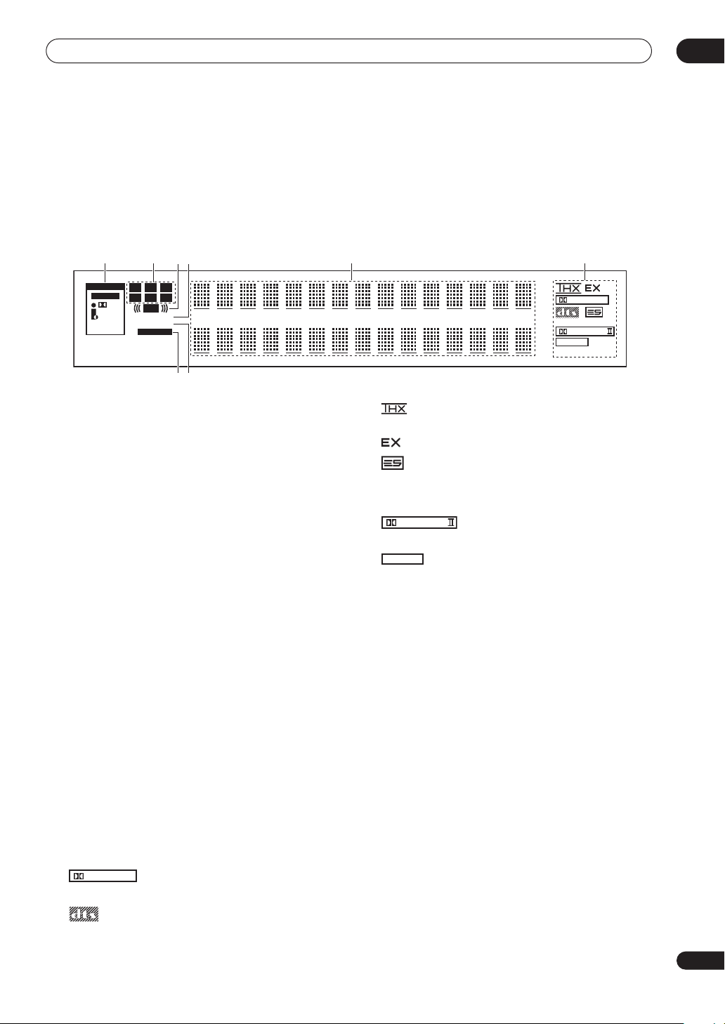
Controls and displays
C
X
K
Chapter 3
Controls and displays
Display
1 2 5 63 4
SIGNAL
L
RF
ENO
CR
LSSR
LFE
OVER ATT
SP
TAPE2
RF ATT
S
B
A
78
AUTO
DIGITAL
ANALOG
RDS
DIGITAL
DISC MTRX
PRO LOGIC
Neo :6
2ch
PLAYBACK
03
1 SIGNAL indicators (page 69)
Light to indicate the currently selected input signal.
AUTO lights when the amplifier is set to select the input
signal automatically.
2 Program format indicators
These change according to which channels are active in
Dolby, DTS, DVD-A and SACD sources.
LS, S and RS will light at the same time to indicate
6.1channel sources.
• L – Left front channel
• C – Center channel
• R – Right front channel
• LS – Left surround channel
• S – Surround channel (mono)
• RS – Right surround channel
• LFE – Low frequency effects channel
3 ((( )))
Lights when an LFE signal is being input.
4 Analog level indicators
OVER indicator
Lights when an analog input signal is too high,
risking distortion. Use the input attenuator to reduce
the level.
ATT indicator (page 70)
Lights when the input attenuator is on.
5 Character display
6 Digital format indicators
• – Lights when a Dolby Digital signal is
DIGITAL
detected.
• – Lights when one of the Home THX modes is
selected.
• – Lights during Surround EX matrix processing.
• – Lights when a decoding DTS-ES audio.
• – Lights during DTS-ES discrete processing.
DIS
• – Lights during DTS-ES matrix processing.
MTR
PRO LOGIC
• – Lights during Dolby Pro Logic II and
Pro Logic IIx processing.
• – Lights during Neo:6 processing with 2-
Neo :6
channel sources.
• – Lights during two-channel
2ch
PLAYBAC
playback.
7 Speaker indicators
Light to indicate the current speaker system, A and/or B.
8 TAPE 2 (page 69)
Lights when the TAPE 2 monitor is switched on.
• – Lights when a DTS signal is detected.
27
En
Page 28
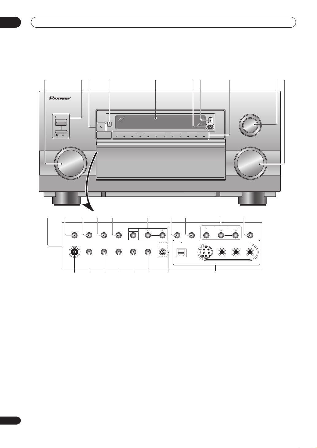
03
Controls and displays
Front panel
1
STANDBY/ON
OFF ON
1211 13 14 16 17 18
23 547
STANDBY
DVD/LD TV/DVD SAT VIDEO
INPUT SELECTOR
VIDEO AUDIO
DVR/VCR1 VCR2 VCR3 CD TUNER PHONO
68 910
AUDIO/VIDEO MULTI-CHANNEL AMPLIFIER
LISTENING MODE SELECTOR
TURN/PUSH
CD-R/
TAPE1/MD
MULTI CH
INPUT
MASTER VOLUME
1915 20
ACOUSTIC
CAL.
PHONES
LOUDNESS OPTIONTONE DIGITAL NR INPUT ATT
MIDNIGHT
SP SYSTEM
SIGNAL
VIDEO
TAPE2
STREAM
A/B
SELECT
SELECT
MONITOR
DIRECT
SETUP
MIC
DIGITAL IN
SELECT
CH LEVEL
VIDEO INPUT
SB CH
MODE
VSA-AX10Ai
28
En
21 22 23 24 25 2726
1 INPUT SELECTOR dial (page 37)
Turn to select a source component. The input indicators
show the current component.
2 STANDBY/ON and power OFF / ON
Press STANDBY/ON to switch the amplifier on or into
standby. The OFF / ON switch turns of the main
power (you can’t switch on using the remote when it is in
the OFF position).
3 STANDBY indicator
Lights when the amplifier is in standby.
4 Remote sensor
Receives the signals from the remote control.
5 Display
See Remote control on page 30.
6 Advaced MCACC indicator (page 44)
Lights when Acoustic Calibration EQ is on. Acoustic
Calibration EQ is automatically set to ALL CH ADJ after
the Auto Surround Setup has been completed.
S-VIDEO VIDEO
AUDIOLR
28
7 i.LINK indicator (page 78)
Lights when an i.LINK-Audio-equipped component is
selected.
8 Input indicators
Shows the currently selected source component. The
MULTI CH INPUT indicator lights when a component
connected to the MULTI CH INPUT is selected. Nothing
lights if an unassigned i.LINK-equipped component or
USB connection is selected.
9 LISTENING MODE SELECTOR dial (page 39)
Turn and push to select a listening mode.
10 MASTER VOLUME dial
Adjusts the volume.
Page 29
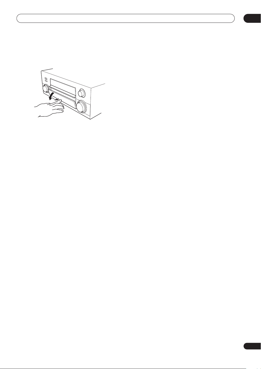
Controls and displays
03
11 Front panel controls
To access the front panel controls, push gently on the
lower third portion of the panel with your finger.
12 ACOUSTIC CAL. (page 44)
Press to switch Acoustic Calibration EQ on or off.
13 MIDNIGHT (page 48)
Press to switch MIDNIGHT mode on/off.
14 LOUDNESS (page 48)
Press to switch LOUDNESS mode on/off.
15 TONE
Press to switch between TONE ON and TONE BYPASS,
which bypasses the tone controls.
16 OPTION (–/+)
Press OPTION repeatedly to select an option menu item,
then use –/+ to adjust the settings.
17 DIGITAL NR (page 49)
Press to switch DIGITAL NR on/off.
18 INPUT ATT (page 70)
Press to switch the input attenuator on/off.
19 CH LEVEL (SELECT/–/+) (page 54)
Press SELECT repeatedly to select a channel, then use –/+
adjust the level.
20 SB CH MODE (page 46)
Use to select the surround/virtual back channel mode.
21 PHONES jack (page 42)
Use to connect headphones (no sound will be heard
through the speakers).
22 SP SYSTEM A/B (page 75)
Press repeatedly to select speaker system A,B, A/B or off
(in that order). (See Caution on page 75 for exceptions to
this).
23 SIGNAL SELECT (page 44)
Press to select the type of input signal for the current
source (DVD, DVR/VCR, etc.), and also to select the
number of input channels for the USB and analog
multichannel inputs.
24 VIDEO SELECT (page 70)
Press repeatedly to select the video source.
25 TAPE 2 MONITOR (page 69)
Press to monitor recordings on the device connected to
the TAPE 2 MONITOR inputs/outputs as they are being
made.
26 STREAM DIRECT (page 43)
Press to switch on/off Stream Direct.
27 SETUP MIC jack
Use to connect the supplied microphone.
28 VIDEO INPUT jacks (page 23)
• DIGITAL IN – Connect a game console, portable DVD
player, video camera (etc.), that has an optical digital
connection.
• S-VIDEO – Connect a video camera (etc.), that has an
S-video out.
• VIDEO / AUDIO (L/R) – Connect a video camera, etc.
that has standard RCA video/audio outputs.
29
En
Page 30
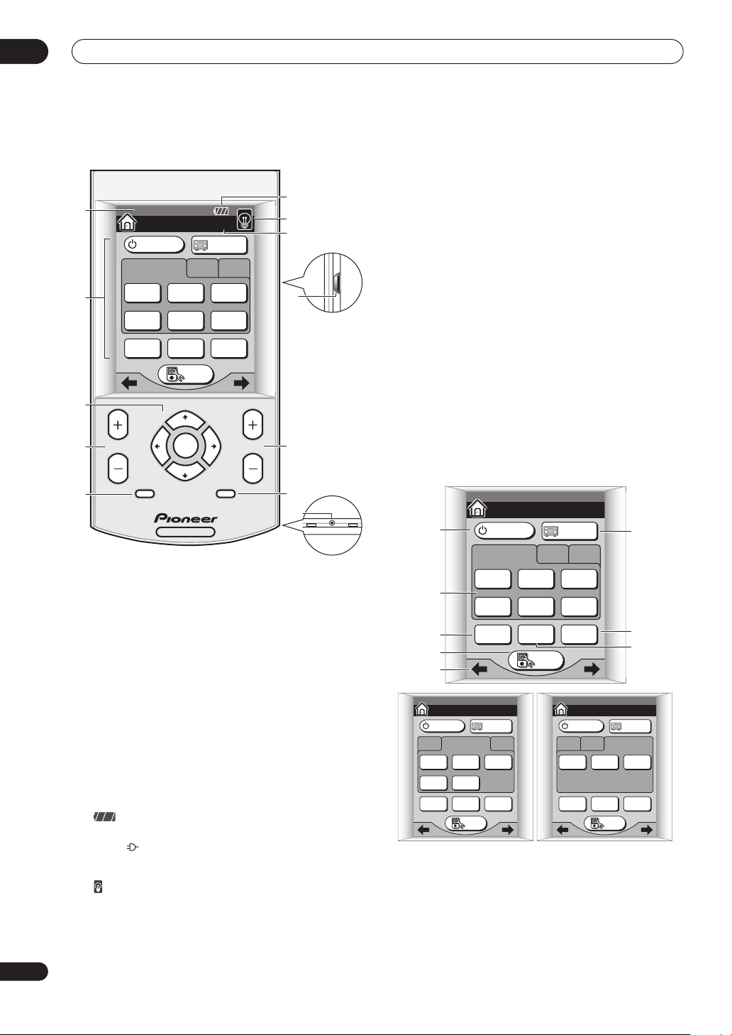
03
Controls and displays
30
En
Remote control
1
07/24 PM 3: 55
HOME 1/3
AMPLIFIER
INPUT 1 2 3
DVD
2
/ LD
DVR
/ VCR1
TV
CONT
AMPLIFIER
TV
/ DVD
CD TUNER
MULTI
OPERATION
SETUP
SAT
SYSTEM
OFF
3
CHANNEL
4
5
SYSTEM
ENTER
MENU MUTE
SETUP
AV AMPLIFIER
VOLUME
1 Date and time display
See Setting the clock on page 9 to set this to the current
time.
2 LCD touch screen
The LCD touch screen appears when the screen is
touched or a button on the remote control is pressed.
3 Cursor hard keys and ENTER
Use to navigate menus and select options/execute
commands.
4 CHANNEL +/–
Use to select channels.
5 MENU / SYSTEM SETUP
Use to display the System Setup menu (or a menu when
controlling other components, such as a DVD or TV).
6
Displays the rechargeable battery status. The recharge
indicator ( ) shows when the remote is being
recharged.
7
Press to switch the touch screen backlight on or off.
8 Menu screen number
Displays the screen number in the current menu, as well
as the number of screens.
6
7
8
9
10
11
12
– +
CONTRAST
9 Contrast control
Use to adjust the contrast of the LCD touch screen.
10 VOLUME +/–
Use to adjust the volume.
11 MUTE
Press to mute all output. Press again (or adjust the
volume using the MASTER VOLUME control) to restore
the sound.
12 Servicing terminal
For use by Pioneer service technicians.
Basic remote control displays
The remote control LCD touch screen has a number of
displays from which you can control amplifier functions,
as well as control operations for other components. The
basic menu screens are explained here.
Home menu screens
There are three Home menu screens, which can be
navigated by using the touch panel / (cursor left/
right) soft keys or INPUT 1, 2 or 3.
HOME
1
2
3
AMPLIFIER
INPUT 1 2 3
DVD
/ DVD
/ LD
DVR
/ VCR1
CONT
TV
CD TUNER
MULTI
OPERATION
4
5
HOME
AMPLIFIER
VCR2
VIDEO
TV
CONT
2/3
AMPLIFIER
INPUT 213
CD-R
VCR3
/ TAPE1
MULTI CH
INPUT
SYSTEM
MULTI
OPERATION
OFF
SETUP
1 AMPLIFIER
Press to switch the amplifier on or into standby.
1/3
AMPLIFIER
TV
SAT
SYSTEM
OFF
SETUP
HOME
AMPLIFIER
i.LINK USB PHONO
TV
CONT
MULTI
OPERATION
SETUP
6
7
8
3/3
AMPLIFIER
INPUT 312
SYSTEM
OFF
Page 31

Controls and displays
03
2 INPUT 1 / 2 / 3
Press 1, 2 or 3 to find the screen with the input source
you want. After pressing the appropriate button to
choose a source, you are taken to the corresponding
function menu (see Operating menus for additional
components below).
3 TV CONT
Press to access the TV control menu (see TV control menu
screens below).
4 SETUP
Press to access the remote control setup menu (see
Setting up the remote control on page 8).
5 / (soft keys)
Press to go to the previous/next Home menu screen.
6 AMPLIFIER
Press to go to the amplifier main menu (see Amplifier
menu screens below).
7 SYSTEM OFF (page 66)
Press to switch off all Pioneer components in your
system, or any other component you have also
programmed to switch off using the System Off function.
8 MULTI OPERATION (page 66)
Use this button to perform multi operations.
Amplifier menu screens
There are three amplifier menu screens, which can be
navigated by using the touch panel / (cursor left/
right) soft keys.
AMPLIFIER 1/3
AMPLIFIER
1
2
SIGNAL
SELECT
LISTENING
MODE
STREAM
DIRECT
ACOUSTIC
CAL.
STEREO
5
6
STANDARD THX
ADVANCED
CINEMA
3
ADVANCED
CONCERT
7
4
1 SIGNAL SELECT (page 44)
Press to select the type of input signal for the current
source (DVD, DVR/VCR1, etc.), and also to select the
number of input channels for the USB and analog
multichannel inputs.
2 LISTENING MODE selector (page 39)
Use to select a listening mode.
3
Press to return to the main Home menu (see Home menu
screens above).
4 / (soft keys)
Press to go to the previous/next amplifier menu screen.
5 STREAM DIRECT (page 43)
Press to select a Stream Direct mode.
6 ACOUSTIC CAL. (page 44)
Press to select an acoustic calibration EQ setting.
7
Press to go to the previous screen (or set of screens).
AMPLIFIER
AMPLIFIER
8
9
MIDNIGHT DIGITAL NR
TONE LOUDNESS
2/3
TV
CONT
12
13
14
10
OPTION
+–
11
CH LEVEL
+–
8 MIDNIGHT (page 48)
Press to switch on/off Midnight listening.
9 TONE (page 48)
Press to switch the tone controls on/off.
10 OPTION (–/+)
Press OPTION repeatedly to select an option menu item,
then use –/+ to adjust the settings.
11 CH LEVEL (+/–) (page 54)
Press CH LEVEL repeatedly to select a channel, then use
–/+ to adjust the level.
12 TV CONT
Press to access the TV control menu (see TV control menu
screens below).
13 DIGITAL NR
Press to switch digital noise reduction on/off (see
Reducing noise during playback on page 49).
31
En
Page 32

03
Controls and displays
14 LOUDNESS (page 48)
Press to switch Loudness on/off.
3/3
TV
CONT
SB CH
MODE
INPUT
AT T
DISPLAY
DIMMER
STATUS
19
20
21
22
15
16
17
18
AMPLIFIER
AMPLIFIER
INPUT
SPEAKER
A/B
VIDEO
SELECT
TAPE2
MONITOR
15 INPUT (page 37)
Press repeatedly to cycle through all possible input
sources.
16 SPEAKER A/B (page 75)
Press repeatedly to select speaker system A,B, A/B or off
(in that order). (See Caution on page 75 for exceptions to
this).
17 VIDEO SELECT (page 70)
Press repeatedly to select the video source.
18 TAPE 2 MONITOR (page 69)
Press to monitor recordings on the device connected to
the TAPE 2 MONITOR inputs/outputs as they are being
made.
19 SB CH MODE (page 46)
Use to select the surround/virtual back channel mode.
20 INPUT ATT (page 70)
Press to switch the input attenuator on/off.
21 DISPLAY DIMMER (page 72)
Use to adjust the brightness of the front panel display.
22 STATUS (page 73)
Press to check selected amplifier settings.
TV control menu screens
SCREEN
SIZE
RETURN
1/3
CLR
CH
6
7
•
0
8
9
TV CONTROL
1
TV
123
2
456
789
3
INPUT
CH
ENTER
4
5
1 TV
Press to switch TV power on/off.
2 Number buttons
Use to select a channel directly.
3 INPUT
Use to select the audio/video input source.
4
Press to return to the main Home menu (see Home menu
screens above).
5 / (soft keys)
Press to go to the previous/next TV control menu screen.
6 SCREEN SIZE
Use to select the screen size on your TV.
7 CLR
Press to clear an entry.
8 CH ENTER
Use to enter channel selections directly.
CH RETURN
Press to return to the channel last selected.
9
Press to go to the previous screen (or set of screens).
32
En
Remote control displays for other
components
The functions on these screens are available once you’ve
programmed the remote to control the appropriate
component (for example, your TV or DVD player). See
Using the remote control with other components on
page 61 for more on this. These screens work in tandem
with the remote control hard keys (see Remote control
above).
Page 33

Controls and displays
TV CONTROL
TV
10
11
10 MPX
Press to mute/restore the sound.
DISPLAY
Press to change the display.
SPLIT
Press to split the screen.
SELECT
Press to select one of the split screens.
P in P
Use for picture-in-picture.
SWAP
Press to swap small and large pictures with P in P.
11 IN1 / IN2 / IN3 / IN4
Press to select a TV input.
MPX DISPLAY
SPLIT
P in P
IN 1 IN 2 IN 3 IN 4
TV CONTROL
TV
12
13
14
15
ANT
AV
selection
BLU GRN RED
SLEEP
2/3
SELECT
SWAP
3/3
FREEZE
YEL
RETURN
16
17
15 SLEEP
Press to set the TV sleep timer.
16 FREEZE
Press to freeze the picture when using a plasma display.
17 RETURN
Press to return to the main menu.
Operating menus for additional components
The example below shows the DVD menu screen.
DVD 1/2
1
DVD
TV
CONT
6
2
3
AUDIO SUBTITLE
DISPLAY TOP MENU
4
7
5
1 DVD
Press to switch DVD power on/off.
2 Playback buttons
/ (backward/forward scan)
Press and hold for fast backward/forward scanning
(play)
Press to start or resume playback.
/ (backward/forward skip)
Press to jump back to the beginning of the
current chapter or track, then to previous chapters.
Press to jump to the next chapter or track.
(stop)
Press to stop the disc (you can resume playback by
pressing (play)).
(pause)
Press to pause playback. Press again to restart.
03
12 ANT
Use to select the type of antenna you’ve connected to
your TV.
13 AV selection
Press to select the programmed picture quality mode.
14 BLU / GRN / RED / YEL
Use to make selections from a TV or other menu.
33
En
Page 34

03
Controls and displays
3 AUDIO
Press to select the audio channel or language.
SUBTITLE
Press to select a subtitle display.
DISPLAY
Press to display/change disc information shown onscreen.
TOP MENU
Press to display the top menu of a DVD disc.
4
Press to return to the main Home menu (see Home menu
screens above).
5 / (soft keys)
Press to go to the previous/next TV control menu screen.
6 TV CONT
Press to access the TV control menu (see TV control menu
screens above).
7
Press to go to the amplifier main menu (see Amplifier
menu screens above).
DVD
DVD
123
8
456
2/2
TV
CONT
CLR
+1 0
10
7890
9
8 Number buttons
Use to directly access tracks, chapters and titles.
9 SEARCH MODE
Use to access the search mode (to jump to a particular
part of the disc).
10 CLR
Press to clear an entry.
11 RETURN
Press to return to a previous menu screen.
SEARCH
MODE
RETURN
11
34
En
Page 35

Getting started
Chapter 4
Getting started
04
Introduction to home theater
You are probably used to using stereo equipment to listen
to music, but may not be used to home theater systems
that give you many more options (such as surround
sound) when listening to soundtracks.
Home theater refers to the use of multiple audio tracks to
create a surround sound effect, making you feel like
you're in the middle of the action or concert. The
surround sound you get from a home theater system
depends not only on the speakers you have set up in your
room, but also on the source and the sound settings of
the amplifier.
DVD-Video has become the basic source material for
home theater due to its size, quality, and ease of use. The
true multichannel audio possible using DVD is what
creates a convincing surround sound effect and gives
you the feeling of ‘being there’.
Follow the steps in Automatically setting up for surround
sound below to achieve the best possible surround
sound by calibrating this amplifier to your listening area.
Automatically setting up for
surround sound
The Auto Surround Setup measures the acoustic
characteristics of your listening area, taking into account
ambient noise, speaker size and distance, and tests for
both channel delay and channel level. After you have set
up the microphone provided with your system, the
amplifier uses the information from a series of test tones
to optimize the speaker settings and equalization for your
particular room.
Make sure you do this before moving on to Playing a
source on page 37.
Important
• Make sure the microphone and speakers are not
moved during the Auto Surround Setup.
• Using the Auto Surround Setup will overwrite any
existing speaker settings in the amplifier.
• After three minutes of inactivity during the Auto
Surround Setup, the OSD will go to sleep until a
button is pressed.
1 Switch on the amplifier and your TV.
If headphones are connected to the amplifier, disconnect
them.
2 Connect the microphone to the SETUP MIC jack
on the front panel.
Make sure there are no obstacles between the speakers
and the microphone.
SB CH
ACOUSTIC
LOUDNESS OPTIONTONE DIGITAL NR INPUT ATT
CAL.
MIDNIGHT
PHONES
SP SYSTEM
SIGNAL
VIDEO
A/B
SELECT
SELECT
TAPE2
STREAM
MONITOR
DIRECT
CH LEVEL
MODE
SELECT
VIDEO INPUT
SETUP
DIGITAL IN
MIC
S-VIDEO VIDEO
AUDIOLR
If you have a tripod, use it to place the microphone so that
it’s about ear level at your normal listening position.
Otherwise, place the microphone at ear level using a
table or a chair.
3 Using the remote control, press AMPLIFIER on
the touch screen, then press the SYSTEM SETUP
button.
TV
/ DVD
CD TUNER
MULTI
OPERATION
SETUP
ENTER
AV AMPLIFIER
1/3
AMPLIFIER
SAT
SYSTEM
OFF
HOME
AMPLIFIER
INPUT 1 2 3
DVD
/ LD
DVR
/ VCR1
TV
CONT
CHANNEL VOLUME
MENU MUTE
SYSTEM
SETUP
An on-screen display (OSD) appears on your TV. Use the
/// hard keys and ENTER on the remote control
to navigate through the screens and select menu items.
• The / (cursor up/down) hard keys select menu
items and the / (cursor left/right) hard keys
change the setting of the item selected.
Caution
• The test tones used in the Auto Surround Setup are
output at high volume.
35
En
Page 36

04
Getting started
4 ‘Auto Surround Setup’ should be highlighted.
Press ENTER.
System Setup
[ Auto Surround Setup ]
[1. Input Assign]
[2. Surround Setup]
[3. Expert Setup]
[4. THX Audio Setup]
[Exit]
5 Specify how you are using your speaker system.
Highlight ‘Go Next’ then press ENTER.
If you are using a normal surround setup, or if you’re not
sure, leave the settings at their default:
• Speaker System Select – Normal Surround
• SP-B (speaker system B) – Second Zone
• X-Curve – ON
For settings other than the default, see Speaker Systems
on page 52.
Auto Surround Setup
Speaker System Select
[ Normal Surround ]
SP–B [Second Zone]
X–Curve [ ON ]
[Go Next]
[Return]
6 Follow the instructions on-screen.
Auto Surround Setup
•Connect microphone
•Please be quiet
•Move obstacles away
•If you have a subwoofer
turn power on and
turn volume up
[Start]
[Cancel]
• Make sure the microphone is connected.
• If you’re using a subwoofer, switch it on and turn up
the volume.
• See below for notes regarding high background
noise levels and other possible interference.
7 Make sure ‘Start’ is selected, then press ENTER.
A progress report is displayed on-screen while the
amplifier outputs test tones to determine the speakers
present in your setup. Try to be as quiet as possible while
it’s doing this.
• Do not to turn down the volume during the test tones.
This may result in incorrect speaker settings.
8 Confirm the speaker configuration in the OSD.
The configuration shown on-screen should reflect the
actual speakers you have.
Check!!
FRONT [ YES ]
CENTER [ YES ]
SURROUND [ YES ]
SURR BACK [ YES
SUB WOOFER
[OK,Go Next]
[Retry]
[ERR Fix SP.]
[Return to Menu]
[ YES ]
X
2]
If the speaker configuration displayed isn’t correct, use
the / (cursor up/down) buttons to select Retry, then
press ENTER. Follow the instructions from step 6.
If the configuration is incorrect and you want to input the
settings manually, select ERRFix SP then press
ENTER. Use / (cursor up/down) to select the speaker
then / (cursor left/right) to specify the size (and
number for surround back). When you’re finished, go to
the next step.
If you see an ERR message in the right side column, there
may be a problem with the speaker connection. If
selecting Retry (above) doesn’t fix the problem, turn off
the power and check the speaker connections.
9 Make sure ‘OK, Go Next’ is selected, then press
ENTER.
A progress report is displayed on-screen while the
amplifier outputs more test tones to determine the
optimum amplifier settings for channel level, speaker
distance, and acoustic calibration EQ.
Auto Surround Setup
Please Wait
Caution!!
Test tone is
output loudly.
[Cancel]
Auto Surround Setup
Now Analyzing
Surround Analysis
Speaker Systems [OK]
Speaker Distance [OK]
Channel Level [OK]
Acoustic Cal EQ [OK]
[Cancel]
•••
Again, try to be as quiet as possible while this is
happening. It may take up to 6 minutes.
36
En
Auto Surround Setup
Please Wait
Caution!!
Test tone is
output loudly.
[Cancel]
Auto Surround Setup
Now Analyzing
Environment Check
Ambient Noise [OK]
Microphone [OK]
Speaker Level [OK]
[Cancel]
•••
Page 37

Getting started
04
10 The Auto Surround Setup has finished! Press
SYSTEM SETUP to exit the System Setup menu.
Auto Surround Setup
! ! Complete ! !
[Data Copy]
[Check]
[Return]
The settings made in the Auto Surround Setup should
give you excellent surround sound from your system, but
it is also possible to adjust these settings manually using
the Surround Setup menu (starting on page 51).
If you plan to go on and make advanced settings at this
point, you can select Data Copy to start customizing
your surround sound settings. See Acoustic Calibration
EQ on page 55 for more on this.
You can also choose to view all the settings by selecting
Check. See Checking your surround settings on page 60
for more on this.
If you selected Return, you can select Exit to leave the
System Setup menu screen.
Note
• If you select Cancel at any time during the Auto
Surround Setup, the amplifier automatically exits
and no settings will be made.
• Remember to disconnect the microphone after
you’ve finished the Auto Surround Setup.
• Check that your DVD player/satellite amplifier is
set to output Dolby Digital, DTS and 88.2/96kHz PCM
(2 channel) audio.
If there is an option for MPEG audio, set this to convert
the MPEG audio to PCM.
If you connected the multichannel analog outputs of the
player to this amplifier, make sure that the player is set to
output multichannel analog audio.
Note
• Depending on your DVD player or source discs you
may only be able to output analog and stereo digital
audio. In this case you need to change the listening
mode to SURROUND if you want multichannel
surround sound.
Playing a source
Here are the basic instructions for playing a source (such
as a DVD disc) with your home theater system.
1 Turn on the power of the playback component
(for example a DVD player), your TV and subwoofer
(if you have one).
• If your source is the TV’s built-in tuner, then switch to
the channel you want to watch, otherwise make sure
that the TV’s video input is set to this amplifier. (For
example, if you connected this amplifier to the VIDEO
1 jacks on your TV, make sure that VIDEO 1 input is
now selected.)
2 If the amplifier isn’t already on, press
AMPLIFIER to switch it on.
Other problems when using the Auto
Surround Setup
If the room environment is not optimal for the Auto
Surround Setup (too much background noise, echo off
the walls, obstacles blocking the speakers from the
microphone) the final settings may be incorrect. Check
for household appliances (air conditioner, fridge, fan,
etc.), that may be affecting the environment and switch
them off if necessary.
Some older TVs may interfere with the operation of the
microphone. If this seems to be happening, switch off the
TV when doing the Auto Surround Setup.
Checking the settings on your DVD
(or other) player
Before continuing, you may want to check the digital
audio output settings on your DVD player and digital
satellite amplifier.
HOME
AMPLIFIER
INPUT 1 2 3
DVD
/ LD
DVR
/ VCR1
TV
CONT
AMPLIFIER
TV
/ DVD
CD TUNER
MULTI
OPERATION
SETUP
1/3
SAT
SYSTEM
OFF
37
En
Page 38

04
Getting started
3 Change the amplifier input to the source you
want to play.
You can use the front panel INPUT SELECTOR knob or
the dedicated INPUT buttons on the remote control
touch screen Home menu (see Basic remote control
displays on page 30 if your unsure how to do this).
AMPLIFIER
TV
/ DVD
CD TUNER
MULTI
OPERATION
SETUP
1/3
SAT
SYSTEM
OFF
HOME
AMPLIFIER
INPUT 1 2 3
DVD
/ LD
DVR
/ VCR1
TV
CONT
4 Start playback of the DVD (or other component).
If you’re playing a Dolby Digital or DTS surround sound
DVD disc, you should hear surround sound. If you are
playing a stereo source, you will only hear sound from the
front left/right speakers in the default listening mode.
• See also Listening to your system on page 39 for
more information on different ways of listening to
sources.
5 Use the MASTER VOLUME control (front panel or
remote) to adjust the volume level.
• Turn down the volume of your TV so that all the sound
is coming from the speakers connected to this
amplifier.
Note
• If you need to manually switch the input signal type
from digital to analog (stereo or multichannel), press
SIGNAL SELECT on the front panel or from the
remote control amplifier menu (see also Using other
functions on page 69).
• For more detailed surround sound setup, see The
Surround Setup menu on page 51.
• With WMA9 Pro, sound problems may occur
depending on your computer system. WMA9 Pro 7.1
channel 96kHz sources will be downsampled to 5.1
channel 48kHz. If sound problems occur please
connect using the USB interface (see Using the USB
interface on page 80).
38
En
Page 39

Listening to your system
Chapter 5
Listening to your system
05
About the listening modes
Using this amplifier you can enjoy listening to sources,
analog or digital, in either stereo or surround sound.
However, the listening mode options and the current
active mode may change depending on your speaker
setup and the type of source you’re listening to.
Note
• The remote control operations in this section are
accessed from the various amplifier menus (for a
more detailed explanation, see Amplifier menu
screens on page 31). To go to the amplifier menu,
press from the remote control Home menu
() and use the / (cursor left/right) soft keys to
go to the previous/next screen.
• You can’t select listening modes when the Stream
Direct mode (see page 43) is switched on.
• With the WMA9 Pro format, 2-channel sources can
only be heard in stereo.
Listening in surround sound
Using this amplifier, you can listen to any source in
surround sound. However, the options available will
depend on your speaker setup and the type of source
you’re listening to.
If you connected surround back speakers, see also Using
the surround back channel on page 46.
See also Using the Advanced surround effects and Using
the Home THX modes below for further stereo and
surround playback options.
AMPLIFIER
HOME
AMPLIFIER
INPUT 1 2 3
DVD
/ LD
DVR
/ VCR1
TV
CONT
AMPLIFIER
TV
/ DVD
CD TUNER
MULTI
OPERATION
SETUP
1/3
SAT
SYSTEM
OFF
AMPLIFIER 1/3
AMPLIFIER
SIGNAL
SELECT
LISTENING
MODE
STANDARD THX
ADVANCED
CINEMA
STREAM
DIRECT
ACOUSTIC
CAL.
STEREO
ADVANCED
CONCERT
Tip
• In the steps below, you can also use the front panel
LISTENING MODE SELECTOR dial instead of the
remote control to select listening modes. Simply turn
the dial to cycle through the available options,
pressing forward to select a mode.
• While listening to a source, press STANDARD for
surround sound playback.
AMPLIFIER 1/3
AMPLIFIER
SIGNAL
SELECT
LISTENING
MODE
STANDARD THX
ADVANCED
CINEMA
STREAM
DIRECT
ACOUSTIC
CAL.
STEREO
ADVANCED
CONCERT
With multichannel sources (such as DVDs and digital
satellite broadcasts), the 2 DIGITAL or DTS indicator on
the front panel lights depending on the source format.
Any active Advanced surround or Home THX mode is
canceled.
With two channel sources, press STANDARD repeatedly
to select from:
• 2 Pro Logic IIx MOVIE – Up to 7.1 channel sound,
especially suited to movie sources
5CH MOVIE+VSB is displayed when the VSB MODE
is switched on
• 2 Pro Logic IIx MUSIC – Up to 7.1 channel sound,
especially suited to music sources
5CH MUSIC+VSB is displayed when the VSB MODE
is switched on
• 2 PRO LOGIC – 4.1 channel surround sound with
sound from the surround speakers in mono
5CH SURR+VSB is displayed when the VSB MODE is
switched on
7 CH SURROUND is displayed when the SB CH
MODE is switched on
• NEO:6 CINEMA – 6.1 channel sound, especially
suited to movie sources
• NEO:6 MUSIC – 6.1 channel sound, especially suited
to music sources
39
En
Page 40

05
Listening to your system
With multichannel sources, if you have connected
surround back speaker(s) and have selected SB CH MODE
ON, you can press STANDARD repeatedly to select:
• 2 Pro Logic IIx MOVIE – See above
• 2 Pro Logic IIx MUSIC – See above
• SX (Studio extension) – Adds surround back channel
sound (taken from the left/right surround output) to
5.1 channel sources
• EX (Extension decode) – Creates surround back
channel sound for 5.1 channel sources and provides
pure decoding for 6.1 channel sources (like Dolby
Digital Surround EX and DTS-ES)
Note
• If the SB CH MODE is switched to OFF, or the
surround back speakers are set to NO, 2 Pro Logic
IIx (above) becomes 2 Pro Logic II (5.1 channel
sound).
• In modes that give 6.1 channel sound, the same
signal is heard from both surround back speakers.
Dolby Pro Logic IIx Music settings
When listening in Dolby Pro Logic IIx Music mode, there
are three further parameters you can adjust: Center
Width, Dimension, and Panorama.
1 With ‘2 Pro Logic IIx MUSIC’ mode active, press
OPTION repeatedly to select CENTER WIDTH,
DIMENSION or PANORAMA.
The remote control menu for this step is shown below
(see note at the start of this chapter if you need help).
OPTION
SETUP
MIC
DIGITAL IN
2/3
TV
CONT
+–
+–
SB CH
CH LEVEL
MODE
VIDEO INPUT
S-VIDEO VIDEO
AUDIOLR
AMPLIFIER
AMPLIFIER
MIDNIGHT DIGITAL NR
TONE LOUDNESS
ACOUSTIC
LOUDNESS OPTIONTONE DIGITAL NR INPUT ATT SELECT
CAL.
MIDNIGHT
PHONES
SP SYSTEM
SIGNAL
VIDEO
A/B
TAPE2
SELECT
SELECT
MONITOR
CH LEVEL
STREAM
DIRECT
• CENTER WIDTH – Provides a better blend of the front
speakers by spreading the center channel between
the front right and left speakers, making it sound
wider (higher settings) or narrower (lower settings).
(This is applicable only when using a center speaker.)
• DIMENSION – Adjusts the depth of the surround
sound balance from front to back, making the sound
more distant (minus settings), or more forward
(positive settings).
• PANORAMA – Extends the front stereo image to
include the surround speakers for a ‘wraparound’
effect.
2 Use the (OPTION) +/– buttons to adjust the
setting.
Center Width is adjustable between 0 and 7 (default : 3);
Dimension between –3 and +3 (default : 0); Panorama is
On or Off (default : Off).
3 Press OPTION again to adjust other settings.
Note
• If the SB CH MODE is switched to OFF, 2 Pro Logic
IIx (above) becomes 2 Pro Logic II (5.1 channel
sound), however the above setting will still be
effective.
Neo:6 Music settings
When listening in Neo:6 Music mode, you can adjust the
center image to create a wider stereo effect with vocals.
1 With NEO:6 MUSIC mode active, press OPTION
repeatedly to select CENTER IMAGE.
The remote control menu for this step is shown below
(see note at the start of this chapter if you need help).
OPTION
SETUP
MIC
CONT
DIGITAL IN
2/3
TV
+–
+–
SB CH
CH LEVEL
MODE
VIDEO INPUT
S-VIDEO VIDEO
AUDIOLR
AMPLIFIER
AMPLIFIER
MIDNIGHT DIGITAL NR
TONE LOUDNESS
ACOUSTIC
LOUDNESS OPTIONTONE DIGITAL NR INPUT ATT SELECT
CAL.
MIDNIGHT
PHONES
SP SYSTEM
SIGNAL
VIDEO
A/B
TAPE2
SELECT
SELECT
MONITOR
CH LEVEL
STREAM
DIRECT
2 Use the (OPTION) +/– buttons to adjust the
setting.
Adjust the effect from 0 (no effect) to 10 (most
prominence given to the center channel). The default
setting is 3.
40
En
Page 41

Listening to your system
05
Using the Advanced surround effects
The Advanced surround effects can be used for a variety
of additional surround sound effects. The Advanced
Cinema modes are designed to be used with movies, and
the Advanced Concert modes are for music.
• Press ADVANCED CINEMA or ADVANCED
CONCERT to select a listening mode.
AMPLIFIER 1/3
AMPLIFIER
SIGNAL
SELECT
LISTENING
MODE
STANDARD THX
ADVANCED
CINEMA
Press ADVANCED CINEMA repeatedly to select from:
• ACTION – Designed for action movies with dynamic
soundtracks
• SCI-FI – Designed for science fiction with lots of
special effects
• DRAMA – Designed for movies with lots of dialog
• MUSICAL – Creates a concert hall-type sound for
musicals
• MONOFILM – Creates surround sound from mono
soundtracks
• 5/7-D THEATER – Creates an extra wide stereo field
Press ADVANCED CONCERT repeatedly to select from:
• CLASSICAL – Gives a large concert hall-type sound
• CHAMBER – Creates a space with alot of reverb
• JAZZ – Creates the sound of a small jazz club
• ROCK – Creates a live concert sound for rock music
• DANCE – Designed for music with lots of bass
• 5/7CH STEREO – Allows you to hear stereo sources
from all the speakers in your setup
STREAM
DIRECT
ACOUSTIC
CAL.
STEREO
ADVANCED
CONCERT
Adjusting the Advanced Surround effect level
You can emphasize or reduce the effect of the Advanced
Surround modes as you like. For each Advanced
Surround mode you can set the effect level
independently.
1 With one of the Advanced surround modes
active, press OPTION repeatedly until EFFECT shows
in the front panel display.
The remote control menu for this step is shown below
(see note at the start of this chapter if you need help).
OPTION
CH LEVEL
SETUP
MIC
CONT
DIGITAL IN
2/3
TV
+–
+–
SB CH
CH LEVEL
MODE
VIDEO INPUT
S-VIDEO VIDEO
AUDIOLR
AMPLIFIER
AMPLIFIER
MIDNIGHT DIGITAL NR
TONE LOUDNESS
ACOUSTIC
LOUDNESS OPTIONTONE DIGITAL NR INPUT ATT SELECT
CAL.
MIDNIGHT
PHONES
SP SYSTEM
SIGNAL
VIDEO
A/B
TAPE2
SELECT
SELECT
MONITOR
STREAM
DIRECT
2 Use the (OPTION) +/– buttons to adjust the effect
level.
The effect level can be adjusted from 10 (min) to 90
(max).
Using the Home THX modes
THX and Home THX are technical standards created by
Lucasfilm Ltd. for cinema and home theater sound.
Home THX is designed to make home theater audio
sound more like what you hear in a cinema. See About
THX® on page 101 for more on this.
Different THX options will be available depending on the
source and the SB CH mode setting (see Using the
surround back channel on page 46 for more on this).
• Press THX to select a THX listening mode.
AMPLIFIER 1/3
AMPLIFIER
SIGNAL
SELECT
LISTENING
MODE
STREAM
DIRECT
ACOUSTIC
CAL.
STEREO
STANDARD THX
ADVANCED
CINEMA
ADVANCED
CONCERT
41
En
Page 42

05
Listening to your system
With two channel sources, press THX repeatedly to select
a matrix-decoding process for the THX CINEMA mode
(see Listening in surround sound above for an
explanation of each process):
• 2 Pro Logic IIx MOVIE
• 2 PRO LOGIC
• NEO:6 CINEMA
With multichannel sources, press THX repeatedly to
select from:
• THX CINEMA – Gives you cinema-quality sound from
your home theatre system using all the speakers in
your setup
• THX SURROUND EX – Allows you to hear 6.1 or 7.1
channel playback with 5.1 channel sources
• 2 Pro Logic IIx MOVIE – Allows you to hear 7.1
channel playback with 5.1 channel sources
(especially suited to movie sources)
• THX ULTRA2 CINEMA – Allows you to hear 7.1
channel playback with 5.1 channel sources
• THX MUSICMODE – Allows you to hear 7.1 channel
playback with DVD-A and SACD multichannel music
sources
Note
• If you only have one surround back speaker
connected, THX ULTRA2 CINEMA and THX
MUSICMODE are not available.
• When selecting the Dolby Pro Logic modes above,
the display shows the mode you selected, then after
a few seconds, shows THX CINEMA.
• You won’t be able to use the THX options when
playing two-channel DVD-A and SACD sources.
• With multichannel DVD-A and SACD sources, you
can only select THX MUSICMODE.
Listening in stereo
You can hear any source through just the front left and
right speakers (and possibly your subwoofer depending
on your speaker settings).
• While listening to a source, press STEREO for
stereo playback.
AMPLIFIER 1/3
AMPLIFIER
SIGNAL
SELECT
LISTENING
MODE
STANDARD THX
ADVANCED
CINEMA
STREAM
DIRECT
ACOUSTIC
CAL.
STEREO
ADVANCED
CONCERT
STEREO shows in the front panel display. Any active
Advanced surround or Home THX mode is canceled.
Dolby Digital and DTS multichannel sources are
downmixed to stereo.
Listening with headphones
When headphones are connected, only the STEREO
(default) and PHONES SURROUND modes are available.
PHONES SURROUND is a virtual surround sound
experience for headphones which provides realistic and
dynamic surround sound.
When you connect a pair of headphones, the listening
mode automatically changes to STEREO or PHONES
SURROUND. When you disconnect them it reverts to the
previous mode.
• With headphones connected, press STANDARD
to select PHONES SURROUND, or STEREO for stereo
sound.
You can also turn the front panel LISTENING MODE
SELECTOR dial to select either STEREO or PHONES
SURROUND.
42
En
Note
• Many features of this amplifier are not accessible
when the headphones are connected.
• If the U-shaped connectors (on the rear panel) aren’t
in place, you won’t be able to use the headphones.
• When headphones are connected, no sound is heard
from the speakers.
• If you’re listening to a WMA9 Pro format source, only
STEREO is available.
Page 43

Listening to your system
Using the multichannel analog inputs
If you’ve connected to the multichannel inputs on the
rear panel (see Connecting the multichannel analog
outputs on page 16), you will be able to select them as
your input source. See Using the Stream Direct mode
below if you want to bypass the signal processing in this
amplifier for a pure analog signal.
1 Press MULTI CH INPUT on the remote control
Home menu ( ) screen.
2 If you want to change the Stream Direct mode,
press OPTION repeatedly to select Stream Direct
(appears on the front panel as SD:1, 2 or 3) then use
the (OPTION) +/– buttons to adjust the setting.
You can also use the front panel INPUT SELECTOR dial.
HOME
AMPLIFIER
VCR2
VIDEO
TV
CONT
2/3
AMPLIFIER
INPUT 213
CD-R
VCR3
/ TAPE1
MULTI CH
INPUT
SYSTEM
MULTI
OPERATION
OFF
SETUP
2 If necessary, press SIGNAL SELECT to choose the
number of channels you’ll hear.
See Selecting USB and multichannel analog input
channels on page 45 for more on this.
Note
• The number of channels you hear will depend on the
source and the SB CH mode setting (see Using the
surround back channel on page 46 for more on this).
Using the Stream Direct mode
• Default setting: SD:1 NORMAL (on)
Use the Stream Direct mode when you want to hear the
truest possible reproduction of a source. All unnecessary
signal processing is bypassed, and you’re left with the
pure analog or digital sound source.
1 While listening to a source, press STREAM
DIRECT to switch on or off.
Check the digital format indicators in the front panel
display to see how the source is being processed.
AMPLIFIER 1/3
AMPLIFIER
SIGNAL
SELECT
LISTENING
MODE
STANDARD THX
ADVANCED
CINEMA
STREAM
DIRECT
ACOUSTIC
CAL.
STEREO
ADVANCED
CONCERT
ACOUSTIC
LOUDNESS OPTIONTONE DIGITAL NR INPUT ATT
CAL.
MIDNIGHT
PHONES
SP SYSTEM
SIGNAL
VIDEO
A/B
SELECT
SELECT
MONITOR
TAPE2
STREAM
SETUP
DIRECT
DIGITAL IN
MIC
SELECT
VIDEO INPUT
S-VIDEO VIDEO
CH LEVEL
MODE
AUDIOLR
SB CH
• SD:1 NORMAL – Analog and digital sources are
heard according to the settings made in the
Surround Setup (speaker setting, channel level,
speaker distance, acoustic calibration EQ, and Xcurve), as well as with dual mono, the input
attenuator, and any sound delay and hi-bit/hisampling settings. You will hear sources according to
the number of channels in the signal.
• SD:2 2CHDIRECT – Use this setting for stereo
analog and digital sources. All processing
unnecessary for 2-channel signals is bypassed (such
as speaker distance and acoustic calibration EQ) and
you will hear the source through the shortest
possible signal path. All sound will be heard through
the front left and right speakers only (no subwoofer
output is heard). With multichannel sources,
playback is the same as the NORMAL setting
(above).
• SD:3 ANADIRECT – All analog sources are heard
without any digital processing. All processing is done
through the analog circuitry and the center channel,
if present, will be sent to the front right and left
speakers (the channel level is adjusted
automatically). With digital sources, playback is the
same as the NORMAL setting (above).
Note
• You can’t use Digital NR, Midnight/Loudness
listening, the SB CH mode, the tone control, or any of
the listening modes when Stream Direct is on.
• If you connect the headphones when SD:3
ANADIRECT is selected, only the front left and
right channels will be heard with multichannel
sources.
• Stereo formats with surround sound information
(such as Dolby Surround) are treated the same as
multichannel sources.
• When the speaker impedance is set to 4Ω in
Switching the speaker impedance on page 72, or
when the Digital Safety is switched on (see
Troubleshooting section on Power on page 92), the
setting is fixed at SD:1 NORMAL.
05
43
En
Page 44

05
Listening to your system
Listening with Acoustic Calibration
EQ
You can listen to sources using the Acoustic Calibration
Equalization set in Automatically setting up for surround
sound on page 35 or Acoustic Calibration EQ on page 55.
Refer to these pages for more on acoustic calibration
equalization.
• While listening to a source, press ACOUSTIC CAL.
to select an Acoustic Calibration EQ setting.
ACOUSTIC
LOUDNESS OPTIONTONE DIGITAL NR INPUT ATT
CAL.
MIDNIGHT
PHONES
SP SYSTEM
SIGNAL
VIDEO
A/B
SELECT
SELECT
MONITOR
AMPLIFIER 1/3
AMPLIFIER
SIGNAL
SELECT
LISTENING
MODE
STANDARD THX
ADVANCED
CINEMA
TAPE2
STREAM
DIRECT
ACOUSTIC
CAL.
STEREO
ADVANCED
CONCERT
SB CH
CH LEVEL
SELECT
STREAM
SETUP
DIRECT
DIGITAL IN
MIC
VIDEO INPUT
S-VIDEO VIDEO
MODE
AUDIOLR
Press repeatedly to select between:
• ALL CH ADJ – No special weighting is given to any
one channel.
• FRONT CH ALIGN – All speakers are heard in
accordance with the front speaker settings.
• CUSTOM 1/2 – Custom settings
• OFF – Switches Acoustic Calibration EQ off.
Selecting the input signal type
Most of the audio inputs have both analog and digital
jacks. You can select the type of signal to be used in each
case.
The input signal type for the current input is indicated in
the display. With digital signals, the signal type (Dolby
Digital or DTS) also shows in the display.
The default AUTO setting is usually sufficient, letting the
amplifier decide the most suitable signal type. However,
if you want to record from the DVR/VCR1 IN/OUT jacks,
then you should set the input signal type to analog.
If you have selected the USB interface or the
multichannel analog inputs as your input source, see
Selecting USB and multichannel analog input channels
below.
• Press SIGNAL SELECT to select the type of input
signal for the current source.
With the remote, you may need to press on the
AMPLIFIER
Home menu ( ) first before reaching the amplifier
menu screen shown below (use the / (cursor left/
right) soft keys to go to the previous/next menu screen).
ACOUSTIC
LOUDNESS OPTIONTONE DIGITAL NR INPUT ATT
CAL.
MIDNIGHT
PHONES
SP SYSTEM
SIGNAL
VIDEO
A/B
SELECT
SELECT
MONITOR
AMPLIFIER 1/3
AMPLIFIER
SIGNAL
SELECT
LISTENING
MODE
STANDARD THX
ADVANCED
CINEMA
TAPE2
STREAM
DIRECT
ACOUSTIC
CAL.
STEREO
ADVANCED
CONCERT
SB CH
CH LEVEL
SELECT
STREAM
SETUP
DIRECT
DIGITAL IN
MIC
VIDEO INPUT
S-VIDEO VIDEO
MODE
AUDIOLR
Press repeatedly to choose between:
• ANALOG – Selects an analog signal.
• – Selects an i.LINK signal.
• DIGITAL – Selects an optical or coaxial digital signal.
• 2 RF – Selects a 2 RF signal.
• AUTO – This is the default setting. The amplifier
selects the first available signal in the following
order: ; 2 RF; DIGITAL; ANALOG.
Note
• If no digital inputs (including the 2 RF input) are
assigned for the current source, the input signal type
will default to ANALOG.
• When using DIGITAL IN terminals the following
digital signal formats are supported: Dolby Digital,
DTS and PCM (32, 44.1, 48, 88.2 and 96 kHz sampling
frequencies). If you are using the i.LINK connectors,
DVD-A (including 176.4/192 kHz) and SACD are also
supported. If your source is not supported, select
ANALOG.
• Some DVD players don’t output DTS signals. For
more details, refer to the instruction manual supplied
with your DVD player.
• Even when i.LINK is selected and the i.LINK indicator
lights, you won’t hear any sound if the output settings
of your i.LINK device are off.
• The audio signal from karaoke microphones and
some LDs is not output from the digital outputs.
Select ANALOG to listen to these formats.
44
En
Page 45

Listening to your system
05
• If you want to play DTS-encoded sources, you need to
have digital connections. If ANALOG is selected,
you’ll hear digital noise through your speakers.
• Make sure you connect your DVD/LD or LD players
using the 2 RF jack. If your player has a 2 RF
output this will ensure you can use all LDs. Refer to
Connecting other video sources on page 19.
• The input signal for unassigned i.LINK-equipped
components is fixed to . See Assigning the i.LINK
inputs on page 84.
• Select the STEREO or STANDARD listening mode
and switch off any other sound processing features.
These features include:
Note that you’ll still be able to use the tone control (see
Using the tone control on page 48).
Selecting USB and multichannel analog input
channels
When you’ve selected the USB interface or the
multichannel analog inputs as your input source, the
SIGNAL SELECT button is used to specify the number of
input channels.
• After selecting USB or MULTI CH IN as your input
source, press SIGNAL SELECT to choose the number
of input channels.
Select one of the following options:
• 2 CHANNEL
• 6 CHANNEL
• 7 CHANNEL
• 8 CHANNEL
The 8 CHANNEL setting is the default.
• Real Phantom (page 47)
• Virtual Surround Back (page 47)
• Midnight/Loudness (page 48)
• Digital Noise Reduction (page 49)
• Dynamic Range Control (page 87)
Note
• You will see the sampling frequency in the display
(with DTS 96kHz (24-bit) sources, 96 is only displayed
when the signal is being processed at 96kHz).
• Even if your DVD player can’t output 96kHz (24-bit)
digital signals, you can still listen to DTS 96/24
sources processed at 96kHz if it has a DTS output
feature. Other formats (such as PCM192/96kHz
sources) are not compatible unless the digital output
of your DVD player supports high-sampling digital
signals.
Listening to high-sampling formats
This amplifier supports 88.2/96kHz (24-bit) digital formats
(such as DTS 96/24 and PCM 96kHz sources up to 24-bit)
when connected to a compatible DVD player with digital
connections. If you have connected this amplifier to an
i.LINK-equipped component, 176.4/192kHz (24-bit) digital
formats (such as DVD-A and SACDs) are also supported.
You can listen to these formats without downsampling in
one of three ways:
• Switch the Stream Direct mode on.
See Using the Stream Direct mode on page 43.
For the following options, the 2 Pro Logic modes cannot
be selected for DTS 96kHz (24-bit) sources without
downsampling:
• Select one of the Home THX modes.
See Using the Home THX modes on page 41.
45
En
Page 46

05
Listening to your system
Using the surround back channel
• Default setting: SB CH ON
You can have the amplifier automatically use 6.1 or 7.1
decoding for 6.1 encoded sources (for example, Dolby
Digital EX or DTS-ES), or you can choose to always use
6.1 or 7.1 decoding with other sources (for example, 5.1
encoded material). With 5.1 encoded sources, a
surround back channel will be generated, but the
Type of source
Dolby Digital EX/DTS-ES encoded
multichannel source with 6.1ch
surround
Dolby Digital/DTS encoded
multichannel source
Dolby Digital/DTS encoded stereo
source; other digital stereo source
Analog 2-channel (stereo) source
• Press SB CH MODE repeatedly to cycle through
the surround back channel options.
The remote control menu for this step is shown below
(see note at the start of this chapter if you need help).
AMPLIFIER
AMPLIFIER
INPUT
SPEAKER
A/B
VIDEO
SELECT
TAPE2
MONITOR
ACOUSTIC
LOUDNESS OPTIONTONE DIGITAL NR INPUT ATT
CAL.
MIDNIGHT
PHONES
SP SYSTEM
SIGNAL
VIDEO
TAPE2
STREAM
A/B
SELECT
SELECT
MONITOR
SETUP
DIRECT
MIC
Each press changes the setting as follows (see the table
above for an explanation of each):
• SB CH AUTO – Automatically switches to 6.1 or 7.1
decoding for 6.1 encoded sources (for example,
Dolby Digital EX or DTS-ES)
• SB CH ON – 6.1 or 7.1 encoding is always used (for
example, on 5.1 encoded material)
SB CH
mode
Multichannel
sources
ON
AUTO
ON
AUTO
ON
AUTO
ON
AUTO
3/3
TV
CONT
SB CH
MODE
INPUT
ATT
DISPLAY
DIMMER
STATUS
SB CH
CH LEVEL
MODE
AUDIOLR
DIGITAL IN
SELECT
VIDEO INPUT
S-VIDEO VIDEO
material may sound better in the 5.1 format for which it
was originally encoded, in which case you can simply
switch the surround back channel off. The table below
indicates when you will hear the surround back channel
when playing various kinds of sources. (
=Sound plays
through surround back channel speaker(s);
SURROUND shows in the display; = Home THX is
selected and two surround back speakers are connected)
Standard / THX
Stereo sources
NEO:6
2 Pro Logic
II x
2 Pro Logic
• SB CH OFF – Surround back channel is switched off
Note
• You will only hear the surround back channel when
you’ve selected SPA as the speaker setting (see
Switching the speaker system on page 75). Changing
the speaker system may automatically change this
setting (see notes below).
• If the surround back speaker is set to NO in Speaker
Systems on page 52, or you have selected SPA+B
as the speaker setting, you can only use the virtual
surround back effect (see next page).
• You can’t select the surround back channel setting (it
is automatically switched off) when you’ve selected
SPB as the speaker setting or when Bi-Surround is
selected in Speaker Systems on page 52.
• You can’t use the surround back channel setting
when Stream Direct is on or when the STEREO mode
is selected.
• When the THX mode is selected, you can’t select SB
CH OFF if you’re listening to DVD-Audio or SACD.
= 7 CH
Advanced
surround
46
En
Page 47

Listening to your system
05
Listening with virtual surround back
speakers
• Default setting: VIRTUAL SB OFF
If you don’t have real surround back speakers connected,
you can use the Virtual Surround Back feature to
simulate one.
Sometimes the material may sound better in the 5.1
format for which it was originally encoded. In this case
you can have the amplifier only apply this effect to 6.1
Creating a center speaker effect
If you don’t have a center speaker connected, the center
speaker channel is mixed to your two front speakers.
However, using the Real Phantom setting, you can create
a center speaker effect for an effective front surround
effect.
1 Press OPTION repeatedly to select R.PHANTOM.
The remote control menu for this step is shown below
(see note at the start of this chapter if you need help).
encoded sources like Dolby Digital EX or DTS-ES (VSB
AUTO), or you can simply switch it off (VSB OFF).
Note that this feature only works when the surround
channels are active and the surround back speaker is set
to NO in Speaker Systems on page 52. It is also available
when the speaker system has been set to SPAB (see
Switching the speaker system on page 75).
See also Using the surround back channel above.
• Press SB CH MODE repeatedly to cycle through
the virtual surround back channel options.
The remote control menu for this step is shown below
(see note at the start of this chapter if you need help).
SETUP
MIC
3/3
TV
CONT
SB CH
MODE
INPUT
ATT
DISPLAY
DIMMER
STATUS
DIGITAL IN
SELECT
VIDEO INPUT
S-VIDEO VIDEO
CH LEVEL
SB CH
MODE
AUDIOLR
2 Use the (OPTION) +/– buttons to change the
setting.
ACOUSTIC
LOUDNESS OPTIONTONE DIGITAL NR INPUT ATT
CAL.
MIDNIGHT
PHONES
SP SYSTEM
SIGNAL
VIDEO
A/B
TAPE2
SELECT
SELECT
MONITOR
AMPLIFIER
AMPLIFIER
INPUT
SPEAKER
A/B
VIDEO
SELECT
TAPE2
MONITOR
STREAM
DIRECT
Each press cycles through the options as follows:
• VSB AUTO
• VSB ON
• VSB OFF
AMPLIFIER
AMPLIFIER
2/3
TV
CONT
MIDNIGHT DIGITAL NR
TONE LOUDNESS
+–
+–
SB CH
CH LEVEL
MODE
SETUP
DIGITAL IN
MIC
VIDEO INPUT
S-VIDEO VIDEO
AUDIOLR
ACOUSTIC
LOUDNESS OPTIONTONE DIGITAL NR INPUT ATT SELECT
CAL.
MIDNIGHT
PHONES
SP SYSTEM
SIGNAL
VIDEO
A/B
TAPE2
SELECT
SELECT
MONITOR
OPTION
CH LEVEL
STREAM
DIRECT
• Mid – A subtle center speaker effect is applied to the
front left and right channels.
• Max – A strong center speaker effect is applied to the
front left and right channels.
• OFF – The center speaker effect is switched off.
Note
• Real Phantom is automatically switched off and
R.PHANTOM won’t appear in the display (in step 1) if
Stream Direct or the STEREO listening mode is
switched on. The center speaker must also be set to
NO in Speaker Systems on page 52.
Note
• You can’t select the virtual surround back setting
when you’ve selected SPB as the speaker setting
(see Caution on page 75) or when Bi-Surround is
selected in Speaker Systems on page 52.
• You can’t use the virtual surround back setting when
Stream Direct is on or when STEREO, or one of the
THX modes is selected.
47
En
Page 48

05
Listening to your system
Using Hi-bit and Hi-sampling
You can use both Hi-bit and Hi-sampling to create a wider
dynamic range with digital sources like CDs or DVDs.
1 Press OPTION repeatedly to select HI-BIT or HISAMPLING.
The remote control menu for this step is shown below
(see note at the start of this chapter if you need help).
OPTION
SETUP
MIC
DIGITAL IN
2/3
TV
CONT
+–
+–
SB CH
CH LEVEL
MODE
VIDEO INPUT
S-VIDEO VIDEO
AUDIOLR
AMPLIFIER
AMPLIFIER
MIDNIGHT DIGITAL NR
TONE LOUDNESS
ACOUSTIC
LOUDNESS OPTIONTONE DIGITAL NR INPUT ATT SELECT
CAL.
MIDNIGHT
PHONES
SP SYSTEM
SIGNAL
VIDEO
A/B
TAPE2
SELECT
SELECT
MONITOR
CH LEVEL
STREAM
DIRECT
2 Use the (OPTION) +/– buttons to switch the
selected mode on or off.
Note
• Hi-bit and Hi-sampling may not work with Stream
Direct or analog sources.
• You can’t use Hi-bit with SACD or sources over
88.2kHz when using one of the digital inputs
(including i.LINK).
Using Midnight and Loudness
listening
• Default setting: Off
The Midnight listening feature allows you to hear
effective surround sound of movies at low volume levels.
The Loudness feature is useful for listening to music
sources at low volumes.
• Press MIDNIGHT or LOUDNESS to switch the
effect on or off.
The remote menu for this step is shown below (see note
at the start of this chapter if you need help).
OPTION
SETUP
MIC
CONT
DIGITAL IN
2/3
TV
+–
+–
SB CH
CH LEVEL
SELECT
VIDEO INPUT
S-VIDEO VIDEO
MODE
AUDIOLR
ACOUSTIC
LOUDNESS OPTIONTONE DIGITAL NR INPUT ATT
CAL.
MIDNIGHT
PHONES
SP SYSTEM
SIGNAL
VIDEO
A/B
SELECT
SELECT
MONITOR
AMPLIFIER
AMPLIFIER
MIDNIGHT DIGITAL NR
TONE LOUDNESS
CH LEVEL
TAPE2
STREAM
DIRECT
Note
• You can’t use the Midnight and Loudness modes at
the same time.
• You can’t use either of these modes when using the
tone controls, or Stream Direct or the Home THX
modes.
• Midnight and Loudness automatically adjust
according to the volume at which you’re listening.
However, the volume must be under -20dB for these
features to take effect.
Using the tone control
You can use the tone control to make customized
settings for the bass and treble.
Switching the tone control on or off
• Default setting: BYPASS
You’ll need to switch the tone control on to adjust the
bass and treble below.
48
En
Page 49

Listening to your system
05
• Press TONE to switch the tone control on or off.
When the tone control is switched off, BYPASS shows in
the display. The remote control menu for this step is
shown below (see note at the start of this chapter if you
need help).
OPTION
SETUP
MIC
CONT
DIGITAL IN
2/3
TV
+–
+–
SELECT
VIDEO INPUT
S-VIDEO VIDEO
CH LEVEL
SB CH
MODE
AUDIOLR
ACOUSTIC
LOUDNESS OPTIONTONE DIGITAL NR INPUT ATT
CAL.
MIDNIGHT
PHONES
SP SYSTEM
SIGNAL
VIDEO
A/B
TAPE2
SELECT
SELECT
MONITOR
AMPLIFIER
AMPLIFIER
MIDNIGHT DIGITAL NR
TONE LOUDNESS
CH LEVEL
STREAM
DIRECT
Note
• You can’t use the tone control with Stream Direct,
Midnight, Loudness, or any of the Home THX modes.
Adjusting the bass and treble
• Default setting: Bass: 0, Treble: 0
You can adjust the bass and treble controls separately to
adjust the overall tone.
1 Press OPTION repeatedly to select BASS or
TREBLE.
The remote control menu for this step is shown below
(see note at the start of this chapter if you need help).
OPTION
2/3
TV
CONT
+–
+–
AMPLIFIER
AMPLIFIER
MIDNIGHT DIGITAL NR
TONE LOUDNESS
CH LEVEL
2 Use the (OPTION) +/– buttons to adjust the
sound.
The bass and treble can be adjusted from –6 to +6.
3 Press ENTER to confirm.
Reducing noise during playback
If you have a noisy source (for example, cassette or video
tape with lots of background noise), you may be able to
improve the quality of the sound by switching on digital
noise reduction (DIGITAL NR).
• Press the DIGITAL NR button to switch digital
noise reduction on or off.
The remote control menu for this step is shown below
(see note at the start of this chapter if you need help).
OPTION
CH LEVEL
SETUP
MIC
CONT
DIGITAL IN
2/3
TV
+–
+–
SB CH
CH LEVEL
SELECT
VIDEO INPUT
S-VIDEO VIDEO
MODE
AUDIOLR
AMPLIFIER
AMPLIFIER
MIDNIGHT DIGITAL NR
TONE LOUDNESS
ACOUSTIC
LOUDNESS OPTIONTONE DIGITAL NR INPUT ATT
CAL.
MIDNIGHT
PHONES
SP SYSTEM
SIGNAL
VIDEO
TAPE2
A/B
SELECT
STREAM
SELECT
MONITOR
DIRECT
Note
• Depending on the source, there may not be a
noticeable improvement in the quality of the sound.
• You can’t use digital noise reduction with Stream
Direct or the Home THX modes.
ACOUSTIC
LOUDNESS OPTIONTONE DIGITAL NR INPUT ATT SELECT
CAL.
MIDNIGHT
PHONES
SP SYSTEM
SIGNAL
VIDEO
A/B
TAPE2
SELECT
SELECT
MONITOR
CH LEVEL
STREAM
SETUP
DIRECT
DIGITAL IN
MIC
VIDEO INPUT
S-VIDEO VIDEO
SB CH
MODE
AUDIOLR
49
En
Page 50

05
Listening to your system
Listening to dual mono soundtracks
You can specify how dual mono encoded Dolby Digital
soundtracks should be played. Dual mono is not widely
used, but is sometimes necessary when two languages
need to be sent to separate channels.
1 Press OPTION repeatedly to select DUAL MONO.
The remote control menu for this step is shown below
(see note at the start of this chapter if you need help).
AMPLIFIER
AMPLIFIER
2/3
TV
CONT
MIDNIGHT DIGITAL NR
TONE LOUDNESS
+–
+–
SB CH
CH LEVEL
MODE
SETUP
DIGITAL IN
MIC
VIDEO INPUT
S-VIDEO VIDEO
AUDIOLR
ACOUSTIC
LOUDNESS OPTIONTONE DIGITAL NR INPUT ATT SELECT
CAL.
MIDNIGHT
PHONES
SP SYSTEM
SIGNAL
VIDEO
A/B
TAPE2
SELECT
SELECT
MONITOR
OPTION
CH LEVEL
STREAM
DIRECT
2 Use the (OPTION) +/– buttons to change the
setting.
• CH1 – Only channel 1 is played
• CH2 – Only channel 2 is played
• CH1/CH2 – Both channels are played through the
front speakers
Note
• On the CH1 and CH2 settings the sound comes only
from the center speaker (or from the front speakers if
NO was selected for the center speaker setting).
• This setting works only with dual mono encoded
Dolby Digital and DTS soundtracks.
• When listening to a dual mono source, the L and R
indicators on the front panel flash. The channel you
select will light in the display.
50
En
Page 51

The Surround Setup menu
Chapter 6
The Surround Setup menu
06
Making amplifier settings from the
Surround Setup menu
This amplifier allows you to make detailed settings to
optimize the surround sound performance. You only
need to make these settings once (unless you change the
placement of your current speaker system or add new
speakers.).
These settings are designed to fine-tune your system, but
if you’re satisfied with the settings made in Introduction
to home theater on page 35, it isn’t necessary to make all
of these settings.
Important
• For many of the settings below, you’ll have to connect
the setup microphone to the front panel and place it
about ear level at your normal listening position. See
Introduction to home theater on page 35 if you’re
unsure how to do this. Also see Other problems when
using the Auto Surround Setup on page 37 for notes
regarding high background noise levels and other
possible interference.
• If you’re using a subwoofer, switch it on and turn up
the volume to the middle position.
• After three minutes of inactivity during the Auto
setup options (including Professional Acoustic
Calibration EQ measurement), the OSD will go to
sleep until a button is pressed. With other screens,
the amplifier automatically exits and no settings will
be made.
Caution
• The test tones used in the Surround Setup are output
at high volume (the volume increases to 0db
automatically).
1 Switch on the amplifier and your TV.
If headphones are connected to the amplifier, disconnect
them.
2 Using the remote control, press AMPLIFIER on
the touch screen, then press the SYSTEM SETUP
button.
TV
/ DVD
CD TUNER
MULTI
OPERATION
SETUP
ENTER
AV AMPLIFIER
1/3
AMPLIFIER
SAT
SYSTEM
OFF
HOME
AMPLIFIER
INPUT 1 2 3
DVD
/ LD
DVR
/ VCR1
TV
CONT
CHANNEL VOLUME
MENU MUTE
SYSTEM
SETUP
An on-screen display (OSD) appears on your TV. Use the
/// hard keys and ENTER on the remote control
to navigate through the screens and select menu items.
• The / (cursor up/down) hard keys select menu
items and the / (cursor left/right) hard keys
change the setting of the item selected.
3 Select ‘Surround Setup’ then press ENTER.
System Setup
[Auto Surround Setup]
[1. Input Assign ]
[2. Surround Setup ]
[3. Expert Setup ]
[4. THX Audio Setup ]
[Exit]
4 Select the setting you want to adjust.
If you are doing this for the first time, you may want to
adjust these settings in order:
2.Surround Setup
[ Check ]
[ 1.Speaker Systems ]
[ 2.Channel Level ]
[ 3.Speaker Distance ]
[ 4.Acoustic Cal EQ ]
[ 5.X-Curve ]
[Return]
51
En
Page 52

06
The Surround Setup menu
• Speaker Systems – Specify the size and number of
speakers you’ve connected (page 52).
• Channel Level – Adjust the overall balance of your
speaker system (page 54).
• Speaker Distance – Specify the distance of your
speakers from the listening position (page 55).
• Acoustic Cal EQ – Adjust overall equalization
depending on your room characteristics (page 55).
• X-Curve – Adjust the amount of ‘re-equalization’
necessary to achieve a flat frequency response from
your home theater system (page 59).
5 Make the adjustments necessary for each
setting, pressing ENTER to confirm after each screen.
When you’re finished, you can check through your
settings screen by screen by selecting Check from the
Surround Setup menu (see Checking your surround
settings on page 60 for more on this).
Speaker Systems
You need to specify the number of speakers you have in
your system, and how you want to route the sound. It is a
good idea to make sure that the settings made in
Introduction to home theater on page 35 are correct.
1 Select ‘Speaker Systems’ then press ENTER.
2.Surround Setup
[ Check ]
[ 1.Speaker Systems ]
[ 2.Channel Level ]
[ 3.Speaker Distance ]
[ 4.Acoustic Cal EQ ]
[ 5.X-Curve ]
[Return]
2 Select how you want to set up your speakers
then press ENTER.
2.1. Speaker Systems
[Manual Free]
[Manual THX]
(all small)
[Auto]
[Return]
• Manual Free – Manually set all speakers.
• Manual THX – All speakers are set to SMALL. You
can only select the number of surround back
speakers.
• Auto – All speakers are set automatically. (The
microphone must be hooked up to the front panel to
do this.)
3 Specify how your speakers are configured.
2.1.Speaker Systems
Manual Free
Speaker System Select
[Normal Surround ]
_
SP
B:
[ Second Zone ]
[ Next]
Use / (cursor left/right) to cycle through the
following options:
• Normal Surround – Select for normal home theater
use.
• Front Bi-Amp – Select this setting if you’re biamping your front speakers (see Bi-amping your front
speakers on page 76).
• Bi-Surround – Select if you’re using two sets of
surround speakers (see Adding a second set of
surround speakers for Bi-Surround on page 77).
If you selected Normal Surround, you’ll also have to
select the speaker system B setting:
2.1.Speaker Systems
Manual Free
Speaker System Select
[Normal Surround ]
_
SP
B:
[ Second Zone ]
[ Next]
• Second Zone – Select if you want to hear speaker
system B in a separate room.
• ITU-R – Select this setting to use two switchable
main speaker systems using speaker system B (see
Alternating surround speaker setups using speaker
system B (ITU-R) on page 76).
• OFF – Select if no speakers are connected to the B
terminals.
4 Press ENTER to go to the next screen.
• If you selected Auto in step 2, you will have to select
Next and then press ENTER to continue to the auto
(test tone) setup.
Select Start and press ENTER to start the test tones
when you’ve made sure the room is free of ambient noise.
Go to step 8 when you see OK appear on the OSD.
52
En
Page 53

The Surround Setup menu
06
5 Choose the set of speakers that you want to set
then select a speaker size.
2.1. Speaker Systems
Manual Free
” Normal Surround ”
FRONT [ LARGE ]
CENTER [ LARGE ]
SURROUND [ LARGE ]
SURR BACK [LARGE
SUB WOOFER [ YES ]
( NEXT)
X
2]
Use / (cursor left/right) to select the size (and
number) of each of the following speakers:
• FRONT – Select LARGE if your front speakers
reproduce bass frequencies effectively, or if you
didn’t connect a subwoofer. Select SMALL to send
the bass frequencies to the subwoofer.
• CENTER – Select LARGE if your center speaker
reproduces bass frequencies effectively, or select
SMALL to send bass frequencies to the other
speakers or subwoofer. If you didn’t connect a center
speaker, choose NO (the center channel is sent to
the front speakers).
• SURROUND – Select LARGE if your surround
speakers reproduce bass frequencies effectively.
Select SMALL to send bass frequencies to the other
speakers or subwoofer. If you didn’t connect
surround speakers choose NO (the sound of the
surround channels is sent to the front speakers or a
subwoofer).
• SURR BACK – Select the number of surround back
speakers you have (one, two or none). Select LARGE
if your surround back speakers reproduce bass
frequencies effectively. Select SMALL to send bass
frequencies to the other speakers or subwoofer. If
you didn’t connect surround back speakers choose
NO.
• SUBWOOFER – LFE signals and bass frequencies of
channels set to SMALL are output from the
subwoofer when YES is selected (see notes below).
Choose the PLUS setting if you want the subwoofer to
output bass sound continuously or you want deeper
bass (the bass frequencies that would normally come
out the front and center speakers are also routed to
the subwoofer). If you did not connect a subwoofer
choose NO (the bass frequencies are output from
other speakers).
Note
• If you selected Manual THX (in step 2) you can only
adjust the surround back settings.
• If you selected Front Bi-Amp (in step 3) you can’t
adjust the surround back settings.
• If you select SMALL for the front speakers the
subwoofer will automatically be fixed to YES. Also,
the center and surround speakers can’t be set to
LARGE if the front speakers are set to SMALL. In this
case, all bass frequencies are sent to the subwoofer.
• If the surround speakers are set to NO, the surround
back speakers will automatically be set to NO.
• If you select one surround back speaker only, make
sure that speaker is hooked up to the left surround
back terminal.
6 Press ENTER to go to the next screen.
7 Choose a crossover frequency.
This setting decides the cutoff between bass sounds
playing back from the speakers selected as LARGE, or
the subwoofer, and bass sounds playing back from those
selected as SMALL. It also decides where the cutoff will
be for bass sounds in the LFE channel.
2.1. Speaker Systems
Manual Free
” Normal Surround ”
Crossover [ 80Hz ]
Normal Surround
(THX Speaker = 80Hz)
SP-B : Second Zone
[Return]
Use / (cursor left/right) to select the crossover
frequency:
• 50Hz – Sends bass frequencies below 50 Hz to the
subwoofer (or LARGE speakers).
• 80Hz – Sends bass frequencies below 80 Hz to the
subwoofer (or LARGE speakers).
• 100Hz – Sends bass frequencies below 100 Hz to the
subwoofer (or LARGE speakers).
• 150Hz – Sends bass frequencies below 150 Hz to the
subwoofer (or LARGE speakers).
• 200Hz – Sends bass frequencies below 200 Hz to the
subwoofer (or LARGE speakers).
Note
• If you selected Manual THX (in step 2) the crossover
frequency is set to 80Hz and this screen doesn’t
appear.
8 Select ‘Return’ and press ENTER to return to the
Surround Setup menu.
Tip
• If you have a subwoofer and like lots of bass, it may
seem logical to select LARGE for your front speakers
and PLUS for the subwoofer. This may not, however,
yield the best bass results. Depending on the speaker
placement of your room you may actually experience
53
En
Page 54

06
The Surround Setup menu
a decrease in the amount of bass due low frequency
cancellations. In this case, try changing the position
or direction of speakers. If you can’t get good results,
listen to the bass response with it set to PLUS and
YES or the front speakers set to LARGE and SMALL
alternatively and let your ears judge which sounds
best. If you’re having problems, the easiest option is
to route all the bass sounds to the subwoofer by
selecting SMALL for the front speakers.
Channel Level
Using the channel level settings, you can adjust the
overall balance of your speaker system, an important
factor when setting up a home theater system. If you’re
unsure of the best channel level settings, simply select
Auto from the setup options below.
1 Select ‘Channel Level’ then press ENTER.
2.Surround Setup
[ Check ]
[ 1.Speaker Systems ]
[ 2.Channel Level ]
[ 3.Speaker Distance ]
[ 4.Acoustic Cal EQ ]
[ 5.X-Curve ]
[Return]
2 Select a setup option and press ENTER to start
the test tones.
2.2. Channel Level
[Manual]
[Semi Auto]
[Auto]
Normal Surround
[Return]
Your Speaker Systems
” Normal Surround ”
• Manual – Move the test tone manually from speaker
to speaker and adjust individual channel levels.
• Semi Auto – Adjust channel levels as the test tone
moves from speaker to speaker automatically.
• Auto – The levels are set automatically by the
amplifier as it outputs the test tones. (For this setup
you must have the mic connected.)
3 If you selected ‘Manual’ or ‘Semi Auto’, adjust
the level of each channel using the / (cursor left/
right) hard keys.
If you selected Manual, use / (cursor up/down) to
switch speakers. The Semi Auto setup will output test
tones in the order shown on-screen:
2.2. Channel Level
Semi Auto
LEFT [ ]
CENTER [ ]
RIGHT [ ]
SURROUND R [ ]
SURR BACK R [ ]
SURR BACK L [ ]
SURROUND L [ ]
SUB WOOFER [ ]
Return = Push Enter
+1. 5
+1. 5
+2. 0
-3. 5
-1. 5
+3. 0
+2. 0
+10. 0
dB
dB
dB
dB
dB
dB
dB
dB
Adjust the level of each speaker as the test tone is
emitted.
Note
• If you are using a Sound Pressure Level (SPL) meter,
take the readings from your main listening position
and adjust the level of each speaker to 75 dB SPL (Cweighting/slow reading).
• The subwoofer test tone is output at low volumes. You
may need to adjust the level after testing with an
actual soundtrack.
4 If you selected ‘Manual’ or ‘Auto’, select ‘Return’
then press ENTER to finish. With ‘Semi Auto’, simply
press ENTER.
With the Auto setup, !! Complete !! is displayed onscreen after the channel levels are set.
2.2. Channel Level
[Manual]
[Semi Auto]
[Auto]
Normal Surround
[Return]
Your Speaker Systems
” Normal Surround ”
To check the settings, select Check and press ENTER
instead of selecting Return above. When you’re finished
select Return then press ENTER.
54
En
Tip
• You can change the channel levels at any time by
using CHANNEL +/– on the front panel or from the
remote control amplifier menu (see Basic remote
control displays on page 30 for more on this). You can
set separate levels for each listening mode
(Standard/Home THX, Advanced Cinema/Advanced
Concert and Stereo) as well as for SB CH ON.
However, these settings will be cleared if you use the
Surround Setup or Auto Surround Sound Setup to set
the channel levels at a later date.
Page 55

The Surround Setup menu
06
Speaker Distance
For good sound depth and separation from your system,
you need to specify the distance of your speakers from
the listening position. The amplifier can then add the
proper delay needed for effective surround sound.
1 Select ‘Speaker Distance’ then press ENTER.
2.Surround Setup
[ Check ]
[ 1.Speaker Systems ]
[ 2.Channel Level ]
[ 3.Speaker Distance ]
[ 4.Acoustic Cal EQ ]
[ 5.X-Curve ]
[Return]
2 Select a setup option and press ENTER.
2.3. Speaker Distance
[Manual]
[Auto]
[Return]
Your Speaker Systems
Normal Surround ”
• Manual – Select each speaker in turn and adjust the
distance manually.
• Auto – The speaker distances are set automatically
by the amplifier as it outputs test tones. (For this
setup you must have the mic connected.)
3 If you selected ‘Auto’, select ‘Start’ and press
ENTER. If you selected ‘Manual’, adjust the distance
of each speaker using the / (cursor left/right)
hard keys.
Using the Manual setup, you can adjust the distance of
each speaker in 0.05 meter increments.
With the Auto setup, !! Complete !! is displayed onscreen after the speaker distances are set. If you want to
check the settings, select Check and press ENTER.
4 Select ‘Return’ then press ENTER to finish.
Tip
• For best surround sound, make sure the surround
back speakers are the same distance.
Acoustic Calibration EQ
Acoustic Calibration Equalization is a kind of room
equalizer for your speakers (excluding the subwoofer). It
works by measuring the acoustic characteristics of your
room and neutralizing the ambient characteristics that
can color the original source material. You can also make
these settings manually to get a frequency balance that
suits your tastes. A more advanced setup is also
available, where you can make detailed settings
according to your room’s reverb characteristics (see
Professional Acoustic Calibration EQ on page 57). You
should have the mic connected when using any of the
setup options.
Setting the Acoustic Calibration EQ automatically
1 Select ‘Acoustic Cal EQ’ then press ENTER.
2.Surround Setup
[ Check ]
[ 1.Speaker Systems ]
[ 2.Channel Level ]
[ 3.Speaker Distance ]
[ 4.Acoustic Cal EQ ]
[ 5.X-Curve ]
[Return]
2 Select ‘Auto’ then press ENTER.
2. 4. Acoustic Cal EQ
[Data Copy]
[Manual]
CUSTOM1 , CUSTOM2
[Auto]
ALL ADJ & FRONT ALIGN
[Professional]
[Return]
As the amplifier outputs test tones, the frequency
balance is adjusted automatically for the following
settings:
• ALL CH ADJ – All the speakers are set individually so
no special weighting is given to any one channel.
• FRONT CH ALIGN – All speakers are set in
accordance with the front speaker settings.
!! Complete !! is displayed on-screen after the acoustic
calibration equalization is set. If you want to check the
settings, select Check and press ENTER.
3 Select ‘Return’ then press ENTER to finish.
Setting the Acoustic Calibration EQ manually
Before manually adjusting the Acoustic Calibration EQ,
we recommend copying the ALL CH ADJ or the FRONT
CH ALIGN settings from the Auto setup above (or from
Introduction to home theater on page 35) to one of the
custom settings. Instead of just a flat EQ curve, this will
give you a reference point from which to start (see
Copying your Acoustic Calibration EQ settings below for
how to do this).
1 Select ‘Acoustic Cal EQ’ then press ENTER.
2.Surround Setup
[ Check ]
[ 1.Speaker Systems ]
[ 2.Channel Level ]
[ 3.Speaker Distance ]
[ 4.Acoustic Cal EQ ]
[ 5.X-Curve ]
[Return]
55
En
Page 56

06
The Surround Setup menu
2 Select ‘Manual’ then press ENTER.
2. 4. Acoustic Cal EQ
[Data Copy]
[Manual]
CUSTOM1 , CUSTOM2
[Auto]
ALL ADJ & FRONT ALIGN
[Professional]
[Return]
3 Select CUSTOM1 or CUSTOM2 then press ENTER.
2.4. Acoustic Cal EQ
[ CUSTOM1 ]
A[ CUSTOM2 ]
[Return]
Manual
4 Select the channel you want, adjust the
frequency curve to your liking, then move to the
next speaker.
2.4. Acoustic Cal EQ
Manual
Target Curve : CUSTOM1
Channel [L•SMALL]
63
[Return]
125
TRIM
1k2k4k
8k
250
500
16k
Use the / (cursor left/right) hard keys to select the
channel, then ENTER to select it.
Use the / (cursor left/right) hard keys to select the
frequency and / (cursor up/down) to boost or cut the
EQ. When you’re finished, press ENTER to move to the
next channel.
Copying your Acoustic Calibration EQ settings
If you want to manually adjust the Acoustic Calibration
EQ (see Setting the Acoustic Calibration EQ manually
above), we recommend copying the ALL CH ADJ or the
FRONT CH ALIGN settings from the Auto setup above
(or from Introduction to home theater on page 35) to one
of the custom settings. Instead of just a flat EQ curve, this
will give you a reference point from which to start.
1 Select ‘Acoustic Cal EQ’ then press ENTER.
2.Surround Setup
[ Check ]
[ 1.Speaker Systems ]
[ 2.Channel Level ]
[ 3.Speaker Distance ]
[ 4.Acoustic Cal EQ ]
[ 5.X-Curve ]
[Return]
2 Select ‘Data Copy’ then press ENTER.
2. 4. Acoustic Cal EQ
[Data Copy]
[Manual]
CUSTOM1 , CUSTOM2
[Auto]
ALL ADJ & FRONT ALIGN
[Professional]
[Return]
3 Select CUSTOM1 or CUSTOM2 then use the /
(cursor left/right) hard keys to select the setting you
want to copy.
2.4. Acoustic Cal EQ
[ CUSTOM1 ]
A[ CUSTOM2 ]
[Return]
Manual
2.4. Acoustic Cal EQ
A.Cal EQ Data Copy
To ← From
CUSTOM1 [ ALL ADJ ]
CUSTOM2 [CUSTOM2 ]
[Copy OK]
[Cancel]
56
En
Tip
• Changing the frequency curve of one channel too
drastically will affect the overall balance. If the
speaker balance seems uneven, you can raise or
lower channel levels using test tones with the TRIM
feature. Use (cursor right) to move to the far right
side of the OSD, then use / (cursor up/down) to
raise or lower the channel level for the current
speaker.
5 When you’re done, press (cursor down) to
select ‘Return’ then press ENTER to finish.
Note
• If the message OVER !! appears on-screen, it means
the frequency curve may result in distortion from the
speaker. Adjust the frequency curve accordingly.
• You can also copy from one custom setting to
another. For more on the ALL CH ADJ and FRONT CH
ALIGN settings, see Setting the Acoustic Calibration
EQ automatically above.
4 Select ‘Copy OK’ and press ENTER to confirm.
You will be taken to the Acoustic Calibration EQ settings
menu. Select Return then press ENTER to go back to the
Surround Setup menu.
Page 57

The Surround Setup menu
06
Professional Acoustic Calibration EQ
This setup minimizes the unwanted effects of room
reverberation by calibrating your system based on the
direct sound coming from the speakers. It can also
provide you with a graphical output of the frequency
response of your room.
Note
• Before setting up with Professional Acoustic
Calibration EQ, you should finish calibrating using
the Auto Surround Setup on page 35.
How to use Professional Acoustic Calibration EQ
If you find that lower frequencies seem overly reverberant
in your listening room (i.e. it sounds ‘boomy’), or that
different channels seem to exhibit different reverb
characteristics, use the auto pro setup to calibrate the
room automatically. This should provide a more balanced
calibration than simply using the standard Acoustic
Calibration EQ. The manual setup allows you to
customize your system calibration with the help of a
graphical output that can be displayed on-screen, or
using a computer (with software available from
Pioneer—see Connecting a PC for Advanced MCACC
output on page 81 for more on this).
How to interpret the graphical output
The graph shows decibels on the vertical axis and time
(in milliseconds) on the horizontal axis. A straight line
indicates a flat-response room (no reverb), whereas a
sloping line indicates the presence of reverberation when
outputting test tones. The sloping line will eventually
flatten out when the reverberant sound stabilizes (this
usually takes about 100ms or so).
By analyzing the graph, you should be able to see how
your room is responding to certain frequencies.
Differences in channel level and speaker distance are
taken into account automatically (compensation is
provided for comparison purposes), but the frequency
measurements are always shown without the
equalization performed by this amplifier.
Note that due to an effect known as ‘group delay’, lower
frequencies will take longer to be generated than higher
frequencies (this is most obvious when comparing the
frequencies at 0ms). This initial slope is not a problem
(i.e. excessive reverb) with your listening room.
Setting Professional Acoustic Calibration EQ
according to your room characteristics
Using the manual setup, you can set the time period at
which the frequency response is analyzed for calibration.
You can pinpoint the time that is best for calibration of
the system for your particular room characteristics.
The graph below shows the difference between standard
acoustic calibration and professional calibration (the
gray circles represent the point at which the microphone
captures the sound for frequency analysis).
Level
Test tone
Acoustic Cal. EQ Pro
calibration range
0 16080
Standard Acoustic Cal.
EQ calibration range
Time
(in msec.)
As soon as audio is output from your speaker system, it
is influenced by room characteristics, such as walls,
furniture, and the dimensions of the room. The sooner
the frequency analysis, the less it is influenced by the
room. We recommend an earlier time setting of 20–40ms
to compensate for two major factors that will influence
the sound of most rooms:
• Reverberance of high vs. low frequencies –
Depending on your room, you may find that lower
frequencies seem overly reverberant compared to
higher frequencies (i.e. your room sounds ‘boomy’).
This may result in a skewed frequency analysis if the
measurement is done too late.
Level
Acoustic Cal. EQ Pro
calibration range
0 16080
Standard Acoustic Cal.
EQ calibration range
Low
frequencies
High
frequencies
Time
(in msec.)
• Reverb characteristics for different channels –
Reverb characteristics can be somewhat different for
each channel. Since this difference increases as the
sound is influenced by the various room
characteristics, it is often better to capture a
frequency analysis early on for smoother mixing of
channel frequencies/sounds.
Level
Acoustic Cal. EQ Pro
calibration range
0 16080
Standard Acoustic Cal.
EQ calibration range
Left
surround
Right
Surround
Time
(in msec.)
If your room isn’t affected by the factors above, it is often
not necessary to make a 20–40ms setting. Later time
settings may provide a more detailed sound experience
with your speaker system. It is best to try and see what
works best for your particular room.
57
En
Page 58

06
The Surround Setup menu
Note that changing the room (for example, moving
furniture or paintings) will affect the calibration results.
In such cases, you should recalibrate your system.
Using Professional Acoustic Calibration EQ
1 Select ‘Acoustic Cal EQ’ then press ENTER.
2.Surround Setup
[ Check ]
[ 1.Speaker Systems ]
[ 2.Channel Level ]
[ 3.Speaker Distance ]
[ 4.Acoustic Cal EQ ]
[ 5.X-Curve ]
[Return]
2 Select ‘Professional’ then press ENTER.
2. 4. Acoustic Cal EQ
[Data Copy]
[Manual]
CUSTOM1 , CUSTOM2
[Auto]
ALL ADJ & FRONT ALIGN
[Professional]
[Return]
3 Select a setup option and press ENTER.
2.4. Acoustic Cal EQ Pro.
” Professional ”
[Auto Pro. ]
Acou. Cal EQ Setup
[Manual Pro. ]al Surround
Reverb Measurement
Reverb View
Advanced EQ Setup
[Return]
• Auto Pro. – The amplifier automatically sets an early
time period (20–40 ms or 60–80 ms) for reverb
measurement, giving you a system calibration based
on the direct sound coming from the speakers. The
frequency balance for each channel is then adjusted
to minimize the effect of the room characteristics on
the overall sound.
• Manual Pro. – You can set an early time period for
reverb measurement manually, giving you the
flexibility to choose the direct sound calibration that
works best with your listening area. After you have
made this setting, the frequency balance for each
channel is adjusted automatically, calibrating your
system according to your custom setting.
4 If you selected ‘Auto Pro.’, select ‘Start’ and press
ENTER.
2.4. Acoustic Cal EQ Pro.
Auto Pro
•Connect microphone
•Please be quiet
•Move obstacles away
•If you have a subwoofer
turn power on and
turn volume up
[Start]
[Cancel]
!! Complete !! is displayed on-screen after the acoustic
calibration equalization is set. Select Return to return to
the professional acoustic calibration equalization menu.
5 Select a manual setup option and press ENTER.
2.4. Acoustic Cal EQ Pro.
Manual Pro.
[ Reverb Measurement ]
[ Reverb View ]
[ Advanced EQ Setup ]
[Return]
• Reverb Measurement – Use this to measure the
reverb characteristics of your room for separate
channels in select frequency ranges.
• Reverb View (Normal) – You can check the reverb
measurements made for specified frequency ranges
in each channel. PC Output will also show as an
option after you’ve completed the reverb
measurement. See Connecting a PC for Advanced
MCACC output on page 81 for more on this option.
• Advanced EQ Setup – Use this to select the time
period that will be used for frequency adjustment and
calibration, based on the reverb measurement of
your listening area. Note that using this setup will
alter the settings you made in Automatically setting
up for surround sound on page 35.
6 If you selected ‘Reverb Measurement’, select
‘Start’ and press ENTER.
2.4. Acoustic Cal EQ Pro.
Reverb
•Connect microphone
•Please be quiet
•Move obstacles away
•If you have a subwoofer
turn power on and
turn volume up
[Start]
[Cancel]
58
En
!! Complete !! is displayed on screen when the reverb
measurement is finished (this may take 2–6 minutes).
After selecting Return, you can select Reverb View
(above) to see the results on-screen. See Connecting a PC
for Advanced MCACC output on page 81 for more on
setting up your computer for the graphical output.
Page 59

The Surround Setup menu
06
7 If you selected ‘Reverb View’, you can use the
cursor buttons (hard keys) to check the reverb
characteristics for each channel. Select ‘Return’ and
press ENTER when you’re done.
2.4. Acoustic Cal EQ Pro.
Reverb View
[ C ]
dB
[ 500Hz ]
080160ms
[Return]
Use the / (cursor left/right) buttons to select the
channel and the frequency you want to check. Use the
/ (cursor up/down) buttons to go back and forth
between the two. Note that the markers on the vertical
axis indicate decibels in 2dB steps.
8 If you selected ‘Advanced EQ Setup’, input the
time setting you want to use for calibration, then
select ‘Go’. Select ‘Start’ from the next screen.
Based on the reverb measurement above, you can
manually choose the time period that will be used for the
final frequency adjustment and calibration. Even though
you can make this setting without reverb measurement,
it is best to use the measurement results as a reference
for your time setting. For an optimal system calibration
based on the direct sound coming from the speakers, we
recommend using the 20–40ms setting.
2.4. Acoustic Cal EQ Pro.
dB
[ C ]
[ 500Hz ]
080160ms
[20~40ms]
[Go]
[Return]
Use the / (cursor left/right) buttons to select the
channel, frequency, and time setting. Use the /
(cursor up/down) buttons to switch between them.
You can switch between your connected speakers
(excluding the subwoofer), and display the
measurements for the following frequencies: 63Hz, 125
Hz, 250Hz, 500Hz, 1kHz, 2kHz, 4kHz, 8kHz and 16kHz.
Select the setting from the following time periods (in
milliseconds): 0–20ms, 10–30ms, 20–40ms, 30–50ms,
40–60ms, 50–70ms and 60–80ms. This setting will be
applied to all channels during calibration.
When you’re finished, select Go. It will take about 2–11
minutes for the calibration to finish.
!! Complete !! is displayed on-screen after the acoustic
calibration equalization is set. If you want to check the
settings, select Check and press ENTER. If you want to
finish, select Return to exit each screen.
X-Curve
Most soundtracks mixed for cinema sound too bright
when played back in large rooms. The X-Curve setting
acts as a kind of re-equalization for home theater
listening, and restores proper tonal balance of movie
soundtracks.
1 Select ‘X-Curve’ then press ENTER.
2. Surround Setup
[ Check ]
[ 1. Speaker Systems ]
[ 2. Channel Level ]
[ 3. Speaker Distance ]
[ 4. Acoustic Cal EQ ]
[ 5. X-Curve ]
[ Return ]
2 Use the / (cursor left/right) hard keys to
switch the X-Curve ON or OFF.
2. 5. X-Curve
X-Curve [ ]
[ Manual ]
[ Semi Auto ]
[ Return ]
Your X-Curve
" –0.5dB/oct "
If you select OFF, the frequency curve will be flat and you
won’t be able to adjust the X-Curve.
3 Select a setup option and press ENTER.
2. 5. X-Curve
X-Curve [ ]
[ Manual ]
[ Semi Auto ]
[ Return ]
Your X-Curve
" –0.5dB/oct "
• Manual – Adjust the X-Curve manually.
• Semi Auto – The X-Curve is calculated automatically.
The larger your listening area (as determined by the
speaker distance setting), the greater the X-Curve
slope (see the following step for more on this).
4 Check the X-Curve setting. If you selected
‘Manual’, make any adjustments necessary to the XCurve.
2.5. X-Curve Manual
X-Curve
[ –2.0dB/oct ]
[ Return ]
ON
ON
631225501k2k4k8k16
59
En
Page 60

06
The Surround Setup menu
Use the / (cursor left/right) hard keys to adjust the
setting. The X-Curve is expressed as a downwards slope
in decibels per octave, starting at 2kHz. The sound
becomes less bright as the slope increases (to a
maximum of -3.0dB/oct). Use the following guidelines to
set the X-Curve according to your room size:
Room size (m2)
X-Curve (dB/oct)
≤≤≤≤36 ≤≤≤≤48 ≤≤≤≤60 ≤≤≤≤72 ≤≤≤≤300
–0.5 –1 –1.5 –2 –2.5 –3
≤≤≤≤1000
5 Select ‘Return’ then press ENTER to finish.
Note
• Since the principal is the same, X-Curve isn’t applied
when you’re using any of the Home THX modes (see
Using the Home THX modes on page 41).
Checking your surround settings
You can check through the amplifier settings screen by
screen after you’re finished using the Surround Setup.
1 Select ‘Check’ from the Surround Setup menu
and press ENTER.
2.Surround Setup
[ Check ]
[ 1.Speaker Systems ]
[ 2.Channel Level ]
[ 3.Speaker Distance ]
[ 4.Acoustic Cal EQ ]
[ 5.X-Curve ]
[Return]
2 Use the / (cursor left/right) hard keys to
cycle through the settings screen by screen.
These appear in the same order as the Surround Setup
menu. Select Return then press ENTER to go back to the
Surround Setup menu.
60
En
Page 61

Controlling other equipment
Chapter 7
Controlling other equipment
07
Using the remote control with other
components
The supplied remote control can operate not only this
amplifier, but also your TV, DVD player and other
components. If the component is listed in the remote
control's memory, simply follow the steps in Recalling
preset codes below. If the component is not listed, or if
you want the remote to learn additional operations, see
Programming signals from other remote controls on
page 63.
Note
• The remote control operations in this section are
accessed from the remote setup menu. To go to the
remote setup menu, press from the remote
control Home menu ( ):
AMPLIFIER
TV
/ DVD
CD TUNER
MULTI
OPERATION
SETUP
1/3
SAT
SYSTEM
OFF
HOME
AMPLIFIER
INPUT 1 2 3
DVR
/ LD
DVR
/ VCR1
TV
CONT
• For more on navigating the remote control menu
screens, see Basic remote control displays on
page 30. See also TV control menu screens on page 32
and Operating menus for additional components on
page 33.
• When using a TV, it is often best to use the TV/DVD
input for the TV source, and TV CONT for the TV
screen or monitor.
SETUP
1/3SETUP
CALIBRATE
PRESET RECALL
LEARNING
MULTI OPERATION
DIRECT FUNCTION
Recalling preset codes
The following steps show you how to recall preset codes
for each input source. Use the remote control touch
screen to do this.
1 Make sure the component you want to control is
switched on.
2 Press PRESET RECALL on the remote setup menu.
1/3SETUP
CALIBRATE
PRESET RECALL
LEARNING
MULTI OPERATION
DIRECT FUNCTION
3 From the ‘Select Function’ screen, choose the
input function which matches the connection for the
component you want to control.
For example, press DVD/LD if you want to control the
DVD player that you connected to the DVD/LD terminals.
Select Function
PRESET RECALL
DVD/LD
TV/DVD
SAT
CANCEL
• Use the / (cursor up/down) buttons to scroll
through the component options.
• You can select any button, but choosing a button
that’s already assigned will overwrite the old preset
(and any other operations you may have
programmed).
61
En
Page 62

07
Controlling other equipment
4 From the ‘Replacing Device’ screen choose the
type of component that you’ve connected.
In this example, we’re setting the remote to control a
DVD player, so we’ll select DVD.
Replacing Device
PRESET RECALL
DVD
TV
DVD recorder
CANCEL
• It is best to have the input source button (DVD/LD)
match the component.
5 From the ‘Setting Makers’ screen, select the
name of the company that makes your component.
Use the / (cursor up/down) buttons to scroll through
the available manufacturers. Here we’ll select Pioneer as
an example.
Setting Makers
PRESET RECALL
Pioneer
AKAI
DENON
CANCELBACK
6 Select a setting type.
There may be only one option listed, or there may be
several. Start with the first button available, which will
show the makers name and 1 (in this case Pioneer-1).
Setting Type
PRESET RECALL
Pioneer-1
Pioneer-2
CANCELBACK
7 Point the remote at the component and press
TRY to test if you've set it up properly.
If the component you are trying to control turns on/off,
the setup for this component is complete and you can go
to step 8.
Following Setting?
PRESET RECALL
device : DVD
maker :
Pioneer
type :
Pioneer-1
TRYINSTALL
CANCELBACK
If the component doesn’t respond, it’s possible that:
• Your component manufacturer has several preset
codes for the same component. Press BACK to go
back and select another number (if there is one) from
the list.
• Your component doesn't have a standby mode (and
therefore won’t switch on/off).
• There is something blocking the path between the
remote control and the remote sensor of the
component you’re trying to control.
• The preset code is unavailable for your component.
Press CANCEL to exit, then try using the method
described in Programming signals from other remote
controls below to program the component into the
remote control. If your component type is different
from the set of controls associated with the input
source (for example you want to control an LD with
the DVD/LD button), it is useful to choose INSTALL
in the next step to change the screen to control the
component you’ve connected.
8 Press INSTALL to confirm and go back to the
‘Select Function’ screen to control another
component.
Following Setting?
PRESET RECALL
device : DVD
maker :
Pioneer
type :
Pioneer-1
TRYINSTALL
CANCELBACK
PLEASE WAIT
62
En
From the Select Function screen (step 3), you can press
to exit and return to the remote control Home menu
screen.
Page 63

Controlling other equipment
07
To exit without saving the preset you have assigned,
press CANCEL instead of INSTALL above.
Tip
• Pioneer DVD recorders fall into the following setting
types:
Pioneer-1 – DVR-7000
Pioneer-2–4 – DVR-3100, DVR-5100H
If you have more than one Pioneer DVD recorder of
setting type 2–4, you can select different setting types
for each (allowing for separate control).
Programming signals from other
remote controls
If the preset code for your component is not available, or
the available preset codes do not operate correctly, you
can program signals from the remote control of another
component. This can also be used to program additional
operations (buttons not covered in the presets) after
assigning a preset code in Recalling preset codes on
page 61.
1 Press LEARNING on the remote setup menu.
SETUP 1/3
CALIBRATE
PRESET RECALL
LEARNING
MULTI OPERATION
DIRECT FUNCTION
2 From the ‘Select Function’ screen, choose the
input function which matches the connection for the
component you want to control.
For example, press DVD/LD if you want to program
signals for the DVD player that you connected to the
DVD/LD terminals.
Select Function
LEARNING
DVD/LD
TV/DVD
SAT
CANCEL
• Use the / (cursor up/down) buttons to scroll
through the component options (the AMPLIFIER and
TUNER screens are not available).
3 On the touch screen, press the button that
corresponds to the command you want to teach the
remote control.
For example, choose the (play) button to program this
remote control to start playback on your DVD player.
DVD
DVD
AUDIO
1/2
TV
CONT
SUBTITLE
END
LEARN
TOP MENUDISPLAY
DVD 2/2
DVD
123CLR
456+10
789
SEARCH
MODE
LEARN
END
TV
CONT
RETURN
0
A remote icon shows in the top right corner of the touch
screen after you’ve selected a button (you can deselect it
by pressing it again).
• Remote control soft keys such as , , /
(cursor left/right) and TV CONT are used to select
menu screens (even in learning mode), so therefore
cannot be programmed.
• The Learn and L buttons that appear on some
component screens are unassigned buttons which
can be used to learn new commands. See Editing
remote control button names on page 64 to change
the name once you’ve programmed a command.
• You can program the remote control hard keys
(VOLUME +/– and MUTE are only available with TV
CONTROL), but the command will remain the same
for all screens of the component selected.
• Press END to go back without making any changes.
4 While the icon is displayed, point the two
remote controls toward each other and press the
button on the other remote control corresponding
to the operation you want to program.
CHANNEL VOLUME
SYSTEM
SETUP
MENU MUTE
AV AMPLIFIER
ENTER
12 – 30 cm
R
R
C
E
V
T
N
/
E
R
E
R
Î
2
C
IV
R
V
E
/
C
V
C
V
T
E
R
R
1
M
E
E
F
R
T
F
N
S
O
C
U
Y
S
V
T
E
N
T
P
O
I
I
A
A
T
T
T
L
S
A
U
/
R
E
M
V
P
T
O
E
D
C
L
/
R
D
U
V
0
D
S
O
R
N
I
E
S
V
E
S
T
E
E
FF
T
E
E
M
E
T
D
O
U
R
I
E
+
+
T
3
P
E
U
C
E
L
O
¢
G
T
N
9
6
3
O
NE
I
T
N
A
A
T
U
C
H
S
N
H
C
E
E
S
-
M
-
F
7
E
ENT
F
4
V
L
E
T
C
D
CH
T
8
5
2
E
L
A
E
R
N
V
T
P
NE
E
H
L
A
+
L
X
+
8
/
W
L
¡
S
G
H
E
MD
V
C
IN
E
B
N
L
U
U
T
S
S
7
D
4
1
S
P
Y
E
S
S
T
T
N
-
-
P
U
I
E
CD
P
M
1
P
R
T
CT
E
U
I
M
N
C
IF
U
FU
M
L
L
S
P
I
O
T
M
V
D
0
10
+
S
S
A
L
C
I
A
N
G
U
L
IN
O
S
R
S
C
T
E
U
C
N
N
L
O
O
N
O
U
R
C
E
R
P
F
E
T
V
I
M
T
N
V
T
T
O
L
O
T
U
C
M
E
M
V
R
T
L
A
T
I
L
IG
T
L
O
D
C
A
T
V
E
N
T
L
G
V
E
A
I
S
S
T
When the command has been learned, OK! shows on
the remote control touch screen and the remote control
returns to the command learning screen (step 3). Repeat
steps 3 and 4 to program additional commands.
If you want to learn signals for additional components,
press END to go back to the Select Function screen and
start again from step 2.
63
En
Page 64

07
Controlling other equipment
Note
• If you see Failed (or OK! doesn’t appear) on the
touch panel, or OK! is displayed, but you find that the
command wasn't learned, try teaching the command
again, but vary the distance (closer or farther)
between the remote controls. Some signals may be
stronger than others and require more distance (a
projector’s remote signal, for example).
• There may be certain remote signals that can’t be
programmed correctly.
• The remote control has a limited memory. If you see
Memory Full appear in the display, use the PRESET
RECALL feature in Recalling preset codes on page 61
to overwrite any programmed buttons that you aren’t
using. This will free up memory to program additional
remote signals.
Remote Direct function
• Default setting: All inputs – ON
On the default setting, when you press an input select
button (DVD/LD, DVR/VCR1, etc.), both the amplifier
input source and the remote control change to the
selected function.
When an input select button is set to OFF, pressing that
button changes the function of the remote control only.
This can be useful when you want to operate one
component without interrupting playback of another.
1 Press DIRECT FUNCTION on the remote setup
menu.
1/3SETUP
CALIBRATE
PRESET RECALL
LEARNING
MULTI OPERATION
DIRECT FUNCTION
2 Choose the setting of an input by pressing the
ON/OFF button on the touch screen.
Each press switches between ON and OFF.
DIRECT FUNCTION
DVD/LD : ON
TV/DVD : ON
SAT : ON
OK
• Use the / (cursor up/down) buttons to scroll
through the component options.
3 Press OK to confirm the settings.
Editing remote control button names
You can rename the buttons on the remote control menu
screens for different input sources (such as DVD/LD or
SAT). You may want to do this if you taught the remote
control a new command in Programming signals from
other remote controls above, but the command doesn’t
correspond with the button name.
1 Press KEY LABEL on the remote setup menu.
SETUP 2/3
CLOCK DISPLAY : AM/PM
CLOCK SETTING
BEEP :
TIMEOUT
KEY LABEL
2 From the ‘Select Function’ screen, select the input
source menu that contains the button you want to
rename.
For example, press DVD/LD if you taught the DVD/LD
remote screen a new command from your DVD player.
64
En
Select Function
KEY LABEL
DVD/LD
TV/DVD
SAT
CANCEL
Page 65

Controlling other equipment
07
3 Select the button you want to rename.
For example, choose the SEARCH MODE button if it was
programmed with the ‘eject’ command from your DVD
player’s remote.
KEY LABEL
DVD
DVD
123CLR
456+10
789
SEARCH
MODE
END
TV
CONT
RETURN
0
• Remote control soft keys such as , , /
(cursor left/right) and TV CONT are used to select
menu screens (even in learning mode), so therefore
cannot be renamed.
• Press END to go back without making any changes.
4 Choose how you want to change the look of the
button.
DVD / LD
KEY LABEL
SEARCH
MODE
SELECT LABEL TYPE
TEXT : LARGE
TEXT : SMALL
GRAPHIC
5 Edit the button as necessary.
If you selected the text input method:
DVD/LD
KEY LABEL
ABCDEFGHI
JKLMNOPQR
STUVWXYZ
OK
CLEAR
SPACE
• Use the letter and number buttons to spell out the
name you want.
• Press SPACE to add a space in the name.
• Press CLEAR to delete characters one at a time.
• Press (small text only) to go to the next line.
• Use the / (cursor left/right) soft keys to go
forward/back a screen.
If you selected the graphic input method:
DVD / LD
KEY LABEL
OKCLEAR
Select one of the following options:
• TEXT : LARGE – Select this if you want to input a
short name, such as EJECT.
• TEXT : SMALL – Select this if the name is fairly long,
for example, DVD Tray Eject.
• GRAPHIC – Select this if you want to replace the
button name with an icon, such as .
• Use the icon buttons to select a graphic.
• Press CLEAR to return to the original button
appearance.
• Press to go back without editing the button.
6 Press OK when you’ve finished.
PLEASE WAIT shows in the remote display while the
name or graphic is input and you’ll return to step 3.
Note
• With power buttons, you won’t be able to delete the
‘’ graphic. These buttons are best left for switching
the component on or off.
• After confirming, you won’t be able to return to the
original button appearance without resetting the
remote control (as described on page 10).
65
En
Page 66

07
Controlling other equipment
Multi Operation and System Off
The Multi Operation feature allows you to program a
series of commands for the components in your system.
For example, you could turn on your TV, turn on your DVD
player and start playing the loaded DVD using only two
buttons on the remote control.
Similar to multi operations, System Off allows you to use
one button to stop and switch off a series of components
in your system at the same time.
Note
• Before Multi Operation and System Off will work
correctly, you must setup the remote to work with
your TV and other components (see Recalling preset
codes on page 61 and Programming signals from
other remote controls on page 63 for more on this).
• Power on and off commands only work with
components that have a standby mode.
Programming a multi operation or a
shutdown sequence
1 Press MULTI OPERATION on the remote setup
menu.
1/3SETUP
CALIBRATE
PRESET RECALL
LEARNING
MULTI OPERATION
DIRECT FUNCTION
2 From the ‘Select Function’ screen, choose the
input function.
This will be the one that starts the multi operation when
you select it as an input source. For example, press DVD/
LD if the multi operation is being used to switch on the
DVD player connected to the DVD/LD terminals.
If you are programming a shutdown (system off)
sequence, select AMPLIFIER from the end of the list.
Select Function
MULTI OPERATION
DVD/LD
TV/DVD
SAT
CANCEL
• Use the / (cursor up/down) buttons to scroll
through the component options.
3 Press ‘Add’ to choose an operation in the
sequence.
If this is the first command in the sequence, the
operation you’re adding will be placed at the top.
Otherwise, the command will simply take the next place
in the sequence.
DVD/LD
MULTI OPERATION
Replace
Add
Delete
Run
Delay OK
4 Choose the component and command you want
to add to the multi operation or shutdown
sequence.
For example, choose DVD/LD from the select function
menu (this now takes the name of the multi-operation
component), then (play) or (stop) from the DVD
menu to start (or stop) playback on your DVD player.
DVD/LD
MULTI OPERATION
DVD/LD
TV/DVD
SAT
CANCEL
MULTI OPERATION
DVD
DVD
AUDIO
CONT
SUBTITLE
TOP MENUDISPLAY
END
1/2
TV
66
En
• Press END to go back without making any changes.
Page 67

Controlling other equipment
07
• You don't need to program the amplifier to switch to
the input function selected in step 2, or to switch on
or off. This is done automatically.
With Pioneer components, you don’t need to:
• program the power to switch off in a shutdown
sequence;
• program the power to switch on if it’s the source
component selected in step 2;
• program a Pioneer TV or monitor to switch on if the
input function (selected in step 2) has video input
terminals;
These take priority in multi operations (not shutdown).
5 If necessary, add a delay between operations by
pressing ‘Delay’.
Some components may take a few seconds to switch on
or off, or perform certain operations. In these cases, you
may want to add a slight delay (up to sixty seconds is
possible) between commands.
Use the + and – buttons on the Delay Time screen to
adjust the delay time then press OK.
DVD/LD
MULTI OPERATION
Delay Time
0.1 sec
–
+
CANCELOK
• To add a new command above another command,
press the existing command before pressing Add.
• To erase a command, select the operation you want
to erase and press Delete.
• Commands will be stored regardless of how you exit
from this screen.
7 Press OK when you’re finished.
PLEASE WAIT shows in the remote display while the
multi operation is stored and you’ll return to step 2.
Using multi operations
You can start multi operations with the amplifier
switched on, or in standby.
1 From the remote control Home menu press
MULTI OPERATION.
AMPLIFIER
TV
/ DVD
CD TUNER
MULTI
OPERATION
SETUP
1/3
SAT
SYSTEM
OFF
HOME
AMPLIFIER
INPUT 1 2 3
DVD
/ LD
DVR
/ VCR1
TV
CONT
2 Press a function button that has been set up with
a multi operation.
The amplifier switches on (if it was in standby) and the
programmed multi operation is performed automatically.
• If you want to change the delay time after it’s been
set, press the delay time, then press SET to come
back to this screen.
6 Repeat steps 3 to 5 for additional commands.
As each command is entered, they will appear in order on
the remote touch screen.
DVD/LD
MULTI OPERATION
DVD PLAY
Delay - 2.0sec
Replace
Add
Delete
Run
Delay OK
• To test the sequence before confirming it, press Run.
• To replace a command in the sequence, select the
command then press Replace. Add the operation as
shown in the steps above.
MULTI OPERATION
Select Function
DVD
/ LDTV/ DVD
DVR
CD
/ VCR1
VCR3
VCR2
MULTI CH
VIDEO
INPUT
CANCEL
SAT
TUNER
CD-R
/ TAPE1
TV
CONT
67
En
Page 68

07
Controlling other equipment
Using System off
• From the remote control Home menu press
SYSTEM OFF.
The command sequence you programmed will run, then
all Pioneer components will switch off, followed by this
amplifier.
AMPLIFIER
TV
/ DVD
CD TUNER
MULTI
OPERATION
SETUP
1/3
SAT
SYSTEM
OFF
HOME
AMPLIFIER
INPUT 1 2 3
DVD
/ LD
DVR
/ VCR1
TV
CONT
Switching components on and off
using the 12 volt trigger
You can connect components in your system (such as a
screen or projector) to this amplifier so that they switch
on or off using a 12 volt trigger when you select an input
function. However, you must specify which input
functions switch on which trigger(s) using the Expert
Setup menu (see 12 Volt Trigger on page 88 to do this).
Note that this will only work with components that have a
standby mode.
• Connect the 12V TRIGGER jack of this amplifier to
the 12V TRIGGER of another component.
Two connections are possible. Use a cable with a mono
mini-plug on each end for each connection.
After you’ve specified the input functions that will switch
on the trigger(s), you’ll be able to switch the component
on or off just by pressing the input function(s) you’ve set
on page 88.
2 Connect the CONTROL OUT jack of that
component to the CONTROL IN jack of another
Pioneer component.
Use a cable with a mono mini-plug on each end for the
connection.
CONTROL
IN OUT
CONTROL
IN OUT
VSA-AX10Ai
S400 (AUDIO)
AUDIO POWER
R L
CONTROL
OUT IN
AMP
IN
MONITOR
OUT 1
MONITOR
OUT 2
DVD/
LD
IN
TV/
DVD
IN
SAT
IN
COMPONENT VIDEO
(DVD/
IN
LD)
Y
IN
Y
1
MONITOR
IN
IN
OUT
P
B
PB
PR
PR
3 Continue the chain in the same way for as many
components as you have.
Note
• If you want to control all your components using this
amplifier’s remote control, refer to Using the remote
control with other components on page 61 and
Programming signals from other remote controls on
page 63.
68
En
Operating other Pioneer components
with this unit’s sensor
Many Pioneer components have SR CONTROL jacks
which can be used to link components together so that
you can use just the remote sensor of one component.
When you use a remote control, the control signal is
passed along the chain to the appropriate component.
Note that if you use this feature, make sure that you also
have at least one set of analog audio jacks connected to
another component for grounding purposes.
1 Decide which component you want to use the
remote sensor of.
When you want to control any component in the chain,
this is the remote sensor at which you’ll point the
corresponding remote control.
Page 69

Using other functions
Chapter 8
Using other functions
08
Making an audio or a video recording
You can make an audio or a video recording from an
audio or video source connected to the amplifier (such as
a CD player or TV).
Keep in mind you can't make a digital recording from an
analog source or vice-versa, so make sure the
components you are recording to/from are hooked up in
the same way (see Connecting your equipment on
page 12 for more on connections).
You can record using composite and S-video
connections interchangeably, but you won’t be able to
record sources connected to the component video
Monitoring your recording
You can listen to (monitor) the recording as it’s being
made if you’ve connected a cassette deck with a
monitoring function to the TAPE 2 MONITOR jacks on
the rear panel.
• Press TAPE 2 MONITOR to switch between the
recorded signal and the original source signal.
With the remote, you may need to press on the
Home menu ( ) first before reaching the amplifier
menu screen shown below (use the / (cursor left/
right) soft keys to go to the previous/next menu screen).
inputs. See About the video converter on page 20 for more
on this.
For more information about video connections, see
Connecting a VCR or DVD recorder on page 18 and
Connecting other video sources on page 19.
1 Select the source you want to record.
Use the INPUT buttons (or the INPUT SELECTOR dial on
the front panel).
2 Select the input signal (if necessary).
Press SIGNAL SELECT to select the input signal
corresponding to the source component (see Selecting
the input signal type on page 44 for more on this).
3 Prepare the source you want to record.
Tune to the radio station, load the CD, video, DVD etc.
4 Prepare the recorder.
Insert a blank tape, MD, video etc. into the recording
device and set the recording levels.
Refer to the instructions that came with the recorder if
you are unsure how to do this. Most video recorders set
the audio recording level automatically—check the
component's instruction manual if you're unsure.
5 Start recording, then start playback of the source
component.
AMPLIFIER
SETUP
MIC
3/3
TV
CONT
SB CH
MODE
INPUT
ATT
DISPLAY
DIMMER
STATUS
DIGITAL IN
SELECT
VIDEO INPUT
S-VIDEO VIDEO
CH LEVEL
SB CH
MODE
AUDIOLR
ACOUSTIC
LOUDNESS OPTIONTONE DIGITAL NR INPUT ATT
CAL.
MIDNIGHT
PHONES
SP SYSTEM
SIGNAL
VIDEO
A/B
SELECT
SELECT
MONITOR
AMPLIFIER
AMPLIFIER
INPUT
SPEAKER
A/B
VIDEO
SELECT
TAPE2
MONITOR
TAPE2
STREAM
DIRECT
Tip
• To record the tape 2 monitor signal to a recorder
connected to the CD-R/TAPE 1 inputs, select any
input (except CD-R/TAPE 1) and switch the tape 2
monitor on.
Note
• The amplifier's volume, tone (bass, treble, Midnight,
Loudness), and surround effects have no effect on
the recorded signal.
• Some digital sources are copy-protected, and can
only be recorded in analog.
• Some video sources are copy-protected. These
cannot be recorded.
69
En
Page 70

08
Using other functions
Reducing the level of an analog
signal
The input attenuator lowers the input level of an analog
signal when it’s too strong. You can use this if you find
the that the OVER indicator is lights often, or you can
hear distortion in the sound.
• From the remote control amplifier menu, press
INPUT ATT to switch the input attenuator on or off.
AMPLIFIER
AMPLIFIER
INPUT
SPEAKER
A/B
VIDEO
SELECT
TAPE2
MONITOR
TAPE2
MONITOR
STREAM
DIRECT
AMPLIFIER
SETUP
MIC
3/3
TV
CONT
SB CH
MODE
INPUT
ATT
DISPLAY
DIMMER
STATUS
DIGITAL IN
VIDEO INPUT
S-VIDEO VIDEO
CH LEVEL
SB CH
MODE
AUDIOLR
You may need to press on the Home menu ( )
first before reaching the amplifier menu screen shown
below (use the / (cursor left/right) soft keys to go to
the previous/next menu screen).
ACOUSTIC
LOUDNESS OPTIONTONE DIGITAL NR INPUT ATT SELECT
CAL.
MIDNIGHT
PHONES
SP SYSTEM
SIGNAL
VIDEO
A/B
SELECT
SELECT
Note
• The attenuator isn’t available with digital sources, or
when using Stream Direct modes 2 or 3.
Adjusting the delay of a soundtrack
Some monitors have a slight delay when showing video,
so the soundtrack will be slightly out of sync with the
picture. By adding a bit of delay, you can adjust the sound
to match the presentation of the video.
1 Press OPTION repeatedly until SOUND DELAY
shows in the display.
VIDEO INPUT
S-VIDEO VIDEO
AMPLIFIER
CH LEVEL
SB CH
MODE
AUDIOLR
With the remote, you may need to press on the
Home menu ( ) first before reaching the amplifier
menu screen shown below (use the / (cursor left/
right) soft keys to go to the previous/next menu screen).
OPTION
SETUP
MIC
DIGITAL IN
2/3
TV
CONT
+–
+–
AMPLIFIER
AMPLIFIER
MIDNIGHT DIGITAL NR
TONE LOUDNESS
ACOUSTIC
LOUDNESS OPTIONTONE DIGITAL NR INPUT ATT SELECT
CAL.
MIDNIGHT
PHONES
SP SYSTEM
SIGNAL
VIDEO
A/B
TAPE2
SELECT
SELECT
MONITOR
CH LEVEL
STREAM
DIRECT
2 Use the (OPTION) +/– buttons to adjust the
amount of delay.
The delay can be adjusted from 0.0–6.0 frames (in 0.1
frame steps).
3 Press ENTER to confirm.
70
En
Note
• When listening to an analog source, you can’t use
sound delay when Stream Direct is on.
• One second is equal to 30 frames of NTSC format
video, and 25 frames of PAL.
Watching video and audio sources
independently
You can listen to a sound source and select a different
video source on your TV.
• While listening to a source, press VIDEO SELECT
to select the video source you want to watch.
With the remote, you may need to press on the
Home menu ( ) first before reaching the amplifier
menu screen shown below (use the / (cursor left/
right) soft keys to go to the previous/next menu screen).
AMPLIFIER
Page 71

Using other functions
SETUP
MIC
3/3
TV
CONT
SB CH
MODE
INPUT
ATT
DISPLAY
DIMMER
STATUS
DIGITAL IN
SELECT
VIDEO INPUT
S-VIDEO VIDEO
CH LEVEL
SB CH
MODE
AUDIOLR
AMPLIFIER
AMPLIFIER
INPUT
SPEAKER
A/B
VIDEO
SELECT
TAPE2
MONITOR
ACOUSTIC
LOUDNESS OPTIONTONE DIGITAL NR INPUT ATT
CAL.
MIDNIGHT
PHONES
SP SYSTEM
SIGNAL
VIDEO
TAPE2
A/B
SELECT
STREAM
SELECT
MONITOR
DIRECT
Press repeatedly to cycle through the possible video
sources. You can select DVD/LD, TV, SAT, VIDEO, DVR/
VCR1, VCR2, VCR3 or OFF (no video signal).
Note
• If you change the source using the input buttons (or
front panel INPUT SELECTOR dial), the system
returns to normal playback.
Enhancing SACD playback
You can get more detail from SACDs by maximizing the
dynamic range (during digital processing) using the
SACD gain feature.
1 Press OPTION repeatedly until SACD GAIN shows
in the display.
With the remote, you may need to press on the
Home menu ( ) first before reaching the amplifier
menu screen shown below (use the / (cursor left/
right) soft keys to go to the previous/next menu screen).
AMPLIFIER
08
2 Use the (OPTION) +/– buttons to switch the SACD
gain between 0dB and 6dB.
For most SACD sources, selecting 6dB will result in high
sound quality and greater detail. The level will be
adjusted automatically for playback at the same volume.
3 Press ENTER to confirm.
Note
• You shouldn’t have any problems using this feature
with most SACD discs, but if the sound distorts, it is
best to switch the gain setting back to 0dB.
Using the A/D converters to give
greater definition to 2-channel sound
This amplifier has high-quality 192kHz (24bit) A/D
converters that can be used in parallel to provide greater
resolution of DSP processing with analog 2-channel
sources. There are two ways to get 192kHz A/D
conversion:
1 Switch the SD:1 NORMAL Stream Direct mode
on.
See Using the Stream Direct mode on page 43 for more on
this.
2 Select the STEREO listening mode and switch off
any other sound processing features.
These features include:
• Midnight/Loudness (page 48)
• Digital Noise Reduction (page 49)
• Dynamic Range Control (page 87)
Also, make sure you also switch the multichannel input
to 2 CHANNEL in Selecting USB and multichannel analog
input channels on page 45.
AMPLIFIER
AMPLIFIER
MIDNIGHT DIGITAL NR
TONE LOUDNESS
ACOUSTIC
LOUDNESS OPTIONTONE DIGITAL NR INPUT ATT SELECT
CAL.
MIDNIGHT
PHONES
SP SYSTEM
SIGNAL
VIDEO
A/B
TAPE2
SELECT
SELECT
MONITOR
OPTION
CH LEVEL
STREAM
DIRECT
2/3
TV
CONT
+–
+–
CH LEVEL
SETUP
DIGITAL IN
MIC
VIDEO INPUT
S-VIDEO VIDEO
SB CH
MODE
AUDIOLR
71
En
Page 72

08
Using other functions
Dimming the display
You can choose between four brightness for the front
panel display. Note that when selecting sources, the
display automatically brightens for a few seconds.
• From the remote control amplifier menu, press
DISPLAY DIMMER repeatedly to change the
brightness of the front panel display.
You may need to press on the Home menu ( )
first before reaching the amplifier menu screen shown
below (use the / (cursor left/right) soft keys to go to
the previous/next menu screen).
AMPLIFIER
AMPLIFIER
RECEIVER
INPUT
SPEAKER
A/B
VIDEO
SELECT
TAPE2
MONITOR
3/3
TV
CONT
SB CH
MODE
INPUT
ATT
DISPLAY
DIMMER
STATUS
Switching the speaker impedance
STANDBY
STREAM
DIRECT
ΩΩ
DVD/LD TV/DVD SAT VIDEO
SETUP
DIGITAL IN
MIC
VIDEO AUDIO
DVR/VCR1 VCR2 VCR3 CD TUNER P
VIDEO INPUT
S-VIDEO VIDEO
CH LEVEL
CD-R/
TAPE1/MD
SB CH
MODE
AUDIOLR
• Default setting: Speaker 6ΩΩ
You can use speakers with a nominal impedance
between 4–16Ω but if you are using speakers with an
impedance of less than 6Ω, you must change the
impedance setting below.
• With the amplifier in standby, press STANDBY/
ON while holding down the OPTION – button.
STANDBY/ON
OFF ON
INPUT SELECTOR
ACOUSTIC
LOUDNESS OPTIONTONE DIGITAL NR INPUT ATT SELECT
CAL.
MIDNIGHT
PHONES
SP SYSTEM
SIGNAL
VIDEO
A/B
TAPE2
SELECT
SELECT
MONITOR
Each time you do this, you switch between the
impedance settings:
• Speaker 4ΩΩΩΩ – Use this setting if your speakers are
rated lower than 6Ω (down to 4Ω).
• Speaker 6ΩΩΩΩ – Use this setting if your speakers are
rated 6Ω–16Ω.
72
En
Note
• If you select Speaker 4ΩΩΩΩ above, the Stream Direct
setting is fixed at SD:1 NORMAL (see Using the
Stream Direct mode on page 43).
Page 73

Using other functions
08
Checking your system settings
Use the status display screen to check the various
settings you’ve made for features such as sound delay,
digital noise reduction, and high-sampling.
1 From the remote control amplifier menu, press
STATUS to check the system settings.
You may need to press on the Home menu ( )
first before reaching the amplifier menu screen shown
below (use the / (cursor left/right) soft keys to go to
the previous/next menu screen).
These appear on both the OSD and the front panel
display.
The front panel display shows each of the following
settings for two seconds each:
Surround back speaker/
Virtual back speaker
Acoustic calibration EQ Dual mono
Digital noise reduction Sound delay
Midnight Hi-bit
Loudness High-sampling
Tone Real phantom
Note
• If the Stream Direct mode is switched on, some
settings above will show OFF, even though they are
switched on.
2 When you’re finished, press STATUS again to
switch off the display.
AMPLIFIER
AMPLIFIER
AMPLIFIER
INPUT
SPEAKER
A/B
VIDEO
SELECT
TAPE2
MONITOR
SB CH MODE :
ACOUS. CAL EQ :
DIGITAL NR :
MIDNIGHT :
LOUDNESS :
TONE CONTROL :
VIDEO SELECT :
DUAL MONO :
SOUND DELAY :
HI-BIT :
HI-SAMPLING :
REAL PHANTOM :
Video select
3/3
TV
CONT
SB CH
MODE
INPUT
ATT
DISPLAY
DIMMER
STATUS
ALL ADJ
OFF
ON
DVD/LD
CH1
0.0frame
OFF
OFF
OFF
OFF
OFF
OFF
Resetting the system
Use this feature to reset the system to its factory default
settings (see Default amplifier settings below).
1 Switch the amplifier into standby.
2 While holding down the front panel DIGITAL NR
button, press and hold STANDBY/ON for about
three seconds.
The display shows RESET?.
3 Press the front panel OPTION + button.
The display shows OK?.
4 Within 5 seconds, press OPTION –.
The amplifier should now be reset.
Note
• This doesn’t affect the presets that you have
programmed into the remote control (see Using the
remote control with other components on page 61).
See Resetting the remote control on page 10 to do
this.
Default amplifier settings
The table below shows the factory default settings. When
you reset the system, the amplifier reverts to these
defaults:
Setting type Default setting Page ref.
Input DVD/LD
Master volume – – – dB (no sound)
Listening mode STANDARD (video inputs,
multichannel inputs, USB)
STEREO (audio inputs)
Advanced surround
effect level
Listening mode (w/
90 (5/7CH STEREO)
50 (all other modes)
STEREO page 42
headphones)
Stream Direct mode SD:1 NORMAL (ON) page 43
Acoustic Calibration EQOFF (switches to ALL CH ADJ
after the Auto Surround Setup)
Input signal select AUTO except multichannel
inputs (ANALOG) and USB
(DIGITAL)
USB / multichannel
8 channels page 45
input channel setting
Surround Back
Channel mode
Virtual Surround Back
ON (with surround back
speaker(s) connected)
OFF page 47
mode
Hi-bit/Hi-sampling OFF page 48
page 39
page 41
page 44
page 44
page 46
73
En
Page 74

08
Using other functions
Setting type Default setting Page ref.
Midnight/Loudness OFF page 48
Tone BYPASS page 48
Digital NR OFF page 49
Dual mono CH1 page 50
Speakers Systems Normal Surround page 52
Speaker B setting Second Zone page 52
Speakers (front,
center, surround,
surround back) setting
Subwoofer setting YES page 53
Crossover frequency 80Hz page 53
Channel levels All 0 dB (no adjustment) page 54
Speaker distance
settings
Acoustic Calibration 0dB (no calibration) page 55
X-Curve OFF (switches to ON after the
Tape 2 monitor OFF page 69
Input attenuator OFF (all inputs) page 70
Sound delay 0.0 frames page 70
SACD gain 0dB page 71
Speaker A/B setting A page 75
Digital jack
assignment
Component video jack
assignment
Video input
assignment
Bass Peak Level OFF (No limit) page 86
Dynamic range
control
OSD overlay ON page 87
12 volt trigger OFF · OFF page 88
THX Ultra2 subwoofer NO page 89
Surround back
speaker position
All SMALL page 53
All 3 m page 55
Auto Surround Setup)
Digital-1 (coaxial) – DVD/LD
Digital-2 (coaxial) – TV/DVD
Digital-3 (coaxial) – CD
Digital-4 (optical) – SAT
Digital-5 (optical) –
Digital-6 (optical) –
CD-R/TAPE1/MD
2 RF (coaxial) – DVD/LD
Component1 – OFF
Component2 – OFF
Component3 – OFF
MULTI IN – OFF
USB – OFF
OFF page 87
0.0–0.3 m page 89
DVR/VCR1
page 59
page 83
page 84
page 85
74
En
Page 75

Other connections
Chapter 9
Other connections
Caution
• Before making or changing the connections, switch
off the power and disconnect the power cord from the
power outlet. Plugging in components should be the
last connection you make with your system.
• Be careful not to allow any contact between speaker
wires from different terminals.
• Note that the + and – connections on speaker
terminals A and B are in opposite positions.
• You can use speakers with a nominal impedance
between 4–16Ω (please see Switching the speaker
impedance on page 72 if you plan to use speakers
with an impedance of less than 6Ω).
Using speaker system B
You can connect a pair of speakers to the B speaker
terminals on the rear panel to listen to stereo playback in
another room, or you can also use these terminals to
hear surround sound when playing DVD-Audio sources.
Once you’ve made these connections, you’ll have to
change the speaker setting in Speaker Systems on
page 52 to specify how you’re using speaker system B.
Switching the speaker system
This unit has three speaker system settings which allow
you to select the speaker system(s) you want to use.
What you will hear depends on the settings you made in
Speaker Systems on page 52. If you selected Normal
Surround for speaker system A, and Second Zone for
speaker system B, sound is output according to the
explanations below.
• Use the SPEAKER A/B button on the remote
control amplifier menu screen to select a speaker
system setting.
You can also use the front panel SP SYSTEM A/B button.
AMPLIFIER
AMPLIFIER
INPUT
SPEAKER
A/B
VIDEO
SELECT
TAPE2
MONITOR
3/3
TV
CONT
SB CH
MODE
INPUT
ATT
DISPLAY
DIMMER
STATUS
ACOUSTIC
LOUDNESS OPTIONTONE DIGITAL NR INPUT ATT
CAL.
MIDNIGHT
PHONES
SP SYSTEM
SIGNAL
VIDEO
A/B
SELECT
SELECT
MONITOR
TAPE2
STREAM
SETUP
DIRECT
DIGITAL IN
MIC
SELECT
VIDEO INPUT
S-VIDEO VIDEO
CH LEVEL
MODE
AUDIOLR
SB CH
Press repeatedly to cycle through the speaker system
options:
• SPA – Sound is output from speaker system A and
the same signal is output from the pre-out terminals.
• SPB – Sound is output from the two speakers
connected to speaker system B. Multichannel
sources will be downmixed to these two speakers.
The same signal is output from the surround back
channel pre-out terminals.
• SPAB – Sound is output from speaker system A (up
to 5 channels, depending on the source), the two
speakers in speaker system B, and the subwoofer.
The sound from speaker system B will be the same as
the sound from speaker system A (multichannel
sources will be downmixed to 2 channels). The same
signal as speaker A is output from the pre-out
terminals, except for the surround back pre-outs,
which output the same signal as speaker B.
• SP (off) – No sound is output from the speakers. The
same sound is output from the pre-out terminals as
when selecting speaker system A (above).
Note
• The subwoofer output depends on the settings you
made in Speaker Systems on page 52. However, if
SPB is selected above, no sound is heard from the
subwoofer (the LFE channel is not downmixed).
• Depending on the settings in Speaker Systems on
page 52 and Using the Stream Direct mode on
page 43, output from the surround back pre-out
terminals may change.
• All speaker systems are switched off when
headphones are connected.
Using speaker system B in another room
Connect a pair of speakers to the speaker B terminals on
the rear panel the same way you connected your
speakers in Connecting the speakers on page 24. Make
sure to review Placing the speakers on page 25 when
placing the speakers in another room.
09
75
En
Page 76

09
Other connections
Alternating surround speaker setups using
speaker system B (ITU-R)
After you connect an alternate set of surround speakers,
you can use speaker system B to provide surround sound
when listening to sources like DVD-Audio discs. This will
give you a setup of 9 speakers where the front and center
speakers can be used with normal 7.1 surround (speaker
system A), or 5.1 surround with DVD-Audio sources
(speaker system B in ITU-R setting).
1 Connect an alternate (ITU-R) set of surround
speakers as shown below.
Connect the ITU-R surround left speaker to the left
speaker terminal of speaker system B. Connect the ITU-R
surround right speaker in the same way.
A
L
FRONT
R
CENTER
L
SURROUND
R
(Single)
L
SURROUND
BACK
R
• Make sure that the + / – connections are properly
inserted (A and B speaker systems are opposite).
2 Select the ‘ITU-R’ setting from the Speaker
Systems menu.
See Speaker Systems on page 52 to specify how you’re
using speaker system B. Normal Surround should be
selected to make this setting.
3 Use the SPEAKER A/B button on the remote
control amplifier menu screen to select a speaker
system setting.
You can also use the SP SYSTEM A/B button on the front
panel.
Choose between the following settings (the shaded
boxes indicate the active speakers in each setup):
• SPA: Normal – Normal surround (for movies, etc.)
B
L
R
ITU-R surround
left speaker
ITU-R surround
right speaker
• SPB: ITU-R – ITU-R surround setup for DVD-Audio
and other multichannel music sources. See Speaker
system setup for DVD-Audio/multichannel music
sources on page 91 for more on this.
• SPOFF– No sound is output from the speakers.
Note
• Depending on the Stream Direct mode, the surround
channel signal(s) will be output from either the
surround, or surround back channel pre-outs when
SPB: ITU-R is selected.
Bi-amping your front speakers
Bi-amping is when you connect the high frequency driver
and low frequency driver of your speakers to different
amplifiers (in this case, to both front and surround back
terminals) for better crossover performance. Your
speakers must be bi-ampable to do this (having separate
terminals for high and low) and the sound improvement
will depend on the kind of speakers you’re using.
1 Connect your speakers as shown below.
This illustration below shows the connections for biamping your front left speaker. Hook up your front right
speaker in the same way.
A
L
FRONT
CENTER
SURROUND
SURROUND
BACK
R
L
R
(Single)
L
R
B
L
R
Front left
speaker
Hi
Lo
76
En
Since both front and surround back speaker terminals
output the same audio, it doesn’t matter which set (front
or surround back) is powering which part (Hi or Low) of
the speaker.
• Make sure that the + / – connections are properly
inserted. (A and B speaker systems are opposite).
Page 77

Other connections
09
2 Select the ‘Front Bi-Amp’ setting from the
Speaker Systems menu.
See Speaker Systems on page 52 to specify how you’re
using the surround back speaker terminals.
Note
• For 7.1 surround sound with this configuration, you
must connect an additional amplifier to the surround
back channel pre-outs. See Connecting additional
amplifiers below for more on this.
Caution
• Most speakers with both Hi and Low terminals have
two metal plates that connect the Hi to the Low
terminals. These must be removed when you are biamping the speakers or you could severely damage
the amplifier. See your speaker manual for more
information.
• If your speakers have a removable crossover network,
make sure you do not remove it for bi-amping. Doing
so may damage your speakers.
Bi-wiring your speakers
The reasons for bi-wiring are basically the same as biamping, but additionally, interference effects within the
wire could be reduced, producing better sound. Again, to
do this your speakers must be bi-wireable (that is they
must have separate terminals for the high and low
frequencies). When bi-wiring, make sure you’ve selected
Normal Surround in Speaker Systems on page 52.
• To bi-wire a speaker, connect two speaker cords
to each speaker terminal on the amplifier.
Adding a second set of surround
speakers for Bi-Surround
If your listening area is quite long, and you are seated far
from the front speakers, you may want to add an extra set
of left and right surround speakers instead of your
surround back speakers. These should be placed
between the front speakers and your existing surround
speakers (which should already be placed on either side
of your listening position).
1 Connect a second set of surround speakers as
shown below.
Connect the second surround left speaker to the
surround back left speaker terminal. Connect the second
surround right speaker in the same way.
A
L
FRONT
R
CENTER
L
SURROUND
R
(Single)
L
SURROUND
BACK
R
• Make sure that the + / – connections are properly
inserted. (A and B speaker systems are opposite).
2 Select the ‘Bi-Surround’ setting from the Speaker
Systems menu.
See Speaker Systems on page 52 to specify how you’re
using the surround back speaker terminals.
2nd surround
left speaker
2nd surround
right speaker
B
L
R
Caution
• Make sure you use a parallel (not series, which are
fairly uncommon) connection when bi-wiring your
speakers.
• Don't connect different speakers from the same
terminal in this way.
Using the pre-outs
Connecting additional amplifiers
This amplifier has more than enough power for any home
use, but it’s possible to add additional amplifiers to every
channel of your system using the pre-outs. If you use
additional amps for the front channels take out the Ushaped connectors (see item 8 in Rear panel on page 12).
Make the connections shown below to add amplifiers to
power your speakers.
77
En
Page 78

09
Other connections
Note
• Before making or changing the connections, switch
off the power and disconnect the power cord from the
AC outlet.
ANALOG
INPUT
DIGITAL
USB AUDIO
IN
PHONO
OUT 2
CD
OUT 1
6
(CD-R/
TUNER
TAPE1/
MD)
IN
5
(DVR/
VCR1)
IN
CD-R/
TAPE1/
4
MD
(SAT)
IN
(CD)
3 IN
TAPE 2
MONITOR
(TV/
2 IN
DVD)
FRONT SUB W CENTER
(DVD/
1 IN
LD)
SURROUND
2RF
(DVD/
IN
LD)
ASSIGNABLE
S400 (AUDIO)
AUDIO
R L
IN
IN
IN
OUT
REC
IN
1
PLAY
(Single)
OUT
REC
IN
PLAY
RL
RL
MULTI CH INPUT
AUDIO POWER
AMP
IN
L
R
CENTER
SUB W.
PRE OUT
2
SURROUND
R L
R L
(Single)
SURROUND
BACK
(Single)
RL
L R
ANALOG
ANALOG
ANALOG
L R
ANALOG
L R
INPUT
INPUT
INPUT
INPUT
Front channel
amplifier
Center channel
amplifier (mono)
Powered subwoofer
Surround
channel
amplifier
Surround back
channel amplifier
• You can use the additional amplifier on the surround
back channel pre-outs for a single speaker as well. In
this case plug the amplifier into the left (L (Single))
terminal only.
Connecting an external stereo pre-amplifier
It’s possible to use a separate stereo pre-amp with this
amplifier if necessary. You might want to do this if you
need to connect more sources than this amplifier can
accommodate, or if you prefer to use a specific pre-amp
for sound quality reasons. You can connect sources to
either this amplifier or to the external pre-amp (giving you
a greater number of input possibilities).
Note that with sources connected this amplifier, any
signal sent to the two front channels will be sent to the
pre-amplifier before being heard through the front
speakers in your system.
1 Remove the U-shaped connectors that connect
the FRONT PRE OUT jacks to the POWER AMP IN
jacks.
2 Use a stereo RCA audio cable to connect the
FRONT PRE OUT jacks of this amplifier to a stereo
input on the pre-amp.
For example, connect to the CD or tape inputs on the rear
of the pre-amp. You’ll have to select that source if you
want to hear the stereo signal from this amplifier.
3 Use a stereo RCA audio cable to connect the
stereo pre-out jacks of the pre-amp to the POWER
AMP IN jack of this amplifier.
This will allow you to hear the stereo source from the
external pre-amp through this amplifier. For stereo
sources connected directly to the external pre-amp, this
amplifier acts as a standard power amplifier. For digital
sources connected to this amplifier, the amplifier acts as
a digital decoder/digital-to-analog converter and as a
power amplifier.
Using the i.LINK interface
If you have a component with an i.LINK connector, you
can connect it to this amplifier using an i.LINK cable.
Since the i.LINK interface does not transmit video
signals, the video signal of i.LINK-connected components must be connected with other cables (see
Connecting your equipment on page 12 for more on
making video connections). If you’ve already hooked up
the video signal from the component, assign the i.LINK
input to the input function to which you’ve connected the
video signals (see Assigning the i.LINK inputs on
page 84).
The two i.LINK connectors on the rear of your amplifier
are 4-pin connectors. Use a 4-pin, S400 i.LINK cable to
connect i.LINK-equipped components.
Caution
• If your i.LINK connector comes into contact with
metallic parts of the amplifier other than the i.LINK
terminal, an electrical short may occur. Some cables
have metal parts that may touch the unit when
connected. Please take care to use a suitable i.LINK
cable only.
Important
• Please use 4-pin, S400 cables less than 3.5 meters
long. Although longer ones are available, they may
not work reliably.
• There may be cases where the PQLS/rate control
function and/or the i.LINK audio does not work properly even when connected to i.LINK Audio-compatible equipment.
• Do not connect/disconnect i.LINK cables or switch
on/off any components connected using i.LINK when
the amplifier is on.
• Copy-protected 96kHz DVD-Video discs can be heard
through the i.LINK connection, but they will be downsampled to 48kHz.
78
En
Page 79

Other connections
09
1 Use an i.LINK cable to connect one of the i.LINK
connectors on this amplifier to an i.LINK connector
on your i.LINK component.
CONTROL
DVD/
LD
IN
TV/
DVD
IN
SAT
IN
OUT
DVR/
VCR1
IN
OUT
VCR2
IN
OUT
VCR3
IN
VIDEOAUDIO S2 VIDEO
MONITOR
OUT 1
MONITOR
OUT 2
COMPONENT VIDEO
(DVD/
IN
LD)
Y
IN
Y
1
MONITOR
IN
IN
OUT
IN
OUT
IN
OUT
IN
OUT
P
B
P
B
PR
PR
IN
IN
3
2
Y
Y
PB
B
P
PR
PR
ASSIGNABLE
12V TRIGGER
RS-232C
DIGITAL
USB AUDIO
IN
AUDIO
R L
PHONO
OUT 2
IN
CD
OUT 1
IN
6
(CD-R/
TUNER
TAPE1/
IN
MD)
IN
5
(DVR/
OUT
VCR1)
REC
IN
CD-R/
TAPE1/
4
MD
(SAT)
IN
IN
PLAY
OUT
(CD)
3 IN
REC
TAPE 2
MONITOR
(TV/
IN
2 IN
DVD)
PLAY
FRONT SUB W CENTER
(DVD/
1 IN
LD)
R
SURROUND
RF
2
(DVD/
IN
LD)
RL
ASSIGNABLE MULTI CH INPUT
S400 (AUDIO)
AUDIO POWER
AMP
IN
RL
CENTER
SUB W.
PRE OUT
1
2
(Single)
SURROUND
R L
R L
(Single)
L
SURROUND
BACK
(Single)
RL
OUT IN
R L
S400
(AUDIO)
i.LINK-equipped component
• The arrow on the cable connector body should be
face down and lined up with the arrow below the
connector on the amplifier for correct alignment. The
i.LINK cable should be inserted straight into the
connector so that it snaps easily into place. If not
connected properly the amplifier will not be able to
recognize any connected components. Note that the
i.LINK cable is fragile and can be broken easily if too
much force is used when connecting.
2 Assign the i.LINK component to the input you
want, then make any necessary output settings on
the component.
See Assigning the i.LINK inputs on page 84 to assign the
component to an input on this amplifier. Follow the
operating instructions that came with the component to
make any necessary output settings.
About i.LINK
i.LINK is a trademark name for IEEE1394, a high-speed
interface for digital audio, video and other data found on
personal computers, digital camcorders, and other kinds
of audio and audio/visual equipment. A single i.LINK
connector can both send and receive data at the same
time, so only one cable is required to connect components for two-way communication.
“i.LINK” and the “i.LINK” logo are trademarks of Sony
Corporation.
About PQLS rate control
Pioneer's PQLS (Precision Quartz Lock System)
technology provides high-precision digital audio from
DVD-A, SACD and audio CD sources when you use the
i.LINK interface. A precision quartz controller in this
amplifier eliminates distortion caused by timing errors
(jitter), giving you the best possible digital-to-analog
conversion from the digital source.
To take advantage of PQLS, you must have a player
compatible with rate-control, and it must be switched on
and connected to this amplifier through the i.LINK
network.
Creating an i.LINK network
Using i.LINK it is possible to chain up to 17 components
together so that the digital audio and control signals
from each component is available to other components
in the network. With the addition of an i.LINK repeater,
it’s possible to connect up to 63 components.
i.LINK connectors come in 4-pin and 6-pin configurations. This player uses the 4-pin connection, but the two
types can be mixed on a network.
This amplifier is compatible with i.LINK Audio (A&M
protocol) components, such as DVD players. Note that
when connected to i.LINK MPEG-II TS equipment (such
as a digital satellite tuner), i.LINK DV equipment (such as
a DVD recorder or DV camcorder), or an i.LINK-equipped
personal computer, audio and video signals are not
transmitted, and connecting to these devices sometimes
causes network interruptions. Check the operating
instructions supplied with your other i.LINK components
for compatibility information.
This amplifier is DTCP (Digital Transmission Content
Protection) compliant, so you can play DVD-A, DVDVideo, and SACD i.LINK audio.
Note
• You can connect several components together using
i.LINK. See Creating an i.LINK network below.
79
En
Page 80

09
X
Other connections
When setting up an i.LINK network, it’s important that
the components form an open ended chain (fig. 1), or a
tree (fig. 2).
fig. 1
fig. 2
i.LINK cable
i.LINK cable
The system will not work if the connected components
form a loop. If a loop is detected, the message LOOP
CONNECT shows in the display. Figs. 3 and 4 show
connections that form a loop.
fig. 3
fig. 4
i.LINK cable
i.LINK cable
Using the USB interface
It is possible to listen to multichannel audio sources from
your computer by connecting to the USB interface on the
rear of this amplifier. Depending on your model of
computer and the software installed, you can listen to
any source compatible with your operating system
through the speaker setup you’ve connected to this
amplifier.
1 Connect your computer’s USB terminal to the
USB terminal on the rear panel of this amplifier.
CONTROL
DVD/
LD
IN
TV/
DVD
IN
SAT
IN
OUT
DVR/
VCR1
IN
OUT
VCR2
IN
OUT
VCR3
IN
VIDEOAUDIO S2 VIDEO
MONITOR
OUT 1
MONITOR
OUT 2
COMPONENT VIDEO
(DVD/
IN
LD)
Y
IN
Y
1
MONITOR
IN
IN
OUT
IN
OUT
IN
OUT
IN
OUT
P
B
P
B
PR
PR
IN
IN
3
2
Y
Y
P
PB
B
PR
PR
ASSIGNABLE
1
DC OUT 12V
12V TRIGGER
RS-232C
TOTAL 100mA MA
2
DIGITAL
USB AUDIO
IN
PHONO
OUT 2
IN
CD
OUT 1
IN
6
(CD-R/
TUNER
TAPE1/
IN
MD)
IN
5
(DVR/
OUT
VCR1)
REC
IN
CD-R/
TAPE1/
4
MD
(SAT)
IN
IN
PLAY
OUT
(CD)
3 IN
REC
TAPE 2
MONITOR
(TV/
IN
2 IN
DVD)
PLAY
FRONT SUB W CENTER
(DVD/
1 IN
LD)
R
SURROUND
RF
2
(DVD/
IN
LD)
RL
ASSIGNABLE MULTI CH INPUT
VSA-AX10Ai
R L
AUDIO
S400 (AUDIO)
AUDIO POWER
RL
CENTER
SUB W.
1
2
(Single)
SURROUND
R L
R L
L
SURROUND
BACK
(Single)
RL
OUT IN
AMP
IN
PRE OUT
(Single)
R L
80
En
Another consideration when connecting i.LINK devices
is the speed of the interface. At present there are three
speeds; S100 (slowest), S200 and S400 (fastest). This
amplifier uses the S400 type. Although you can use
components with different speeds together, we
recommend connecting slower-speed components at
the edge of the network if possible (shown by the shaded
boxes in figs. 1 and 2). This will keep the network free of
bottlenecks.
When used within an i.LINK network, this amplifier must
be on for the i.LINK connection to be maintained. Other
components in the network may or may not maintain the
connection in standby (none will when the power is
completely off)—check the operating instructions
supplied with individual components. Note that the audio
may be momentarily interrupted if a component in the
i.LINK network is switched on/off, or its i.LINK
connection is switched on/off.
This product complies with the following i.LINK interface
specifications:
1) IEEE Std. 1394a-2000, Standard for a High Performance
Serial Bus
2) Audio and Music Data Transmission Protocol 2.0
Following the standard for AM824 sequence adaptation
layers, the product is compatible with IEC60958 bitstream,
DVD-A and SACD.
Personal computer
2 Switch on your computer and this amplifier.
3 If you’re connecting for the first time, wait for
the USB driver installation to finish.
The installation may take a minute or two to complete.
Make sure you leave the USB cable connected until the
dialog box indicates that the USB setup is finished. Note
that some older operating systems may require a disc for
installation.
4 Press ‘USB’ on the remote control Home menu
() screen.
You can also use the INPUT SELECTOR dial on the front
panel to select USB.
5 Make any necessary settings required to select
the USB interface as your computer audio output.
You will need to access your speaker settings from the
Control Panel of your operating system:
• Windows
®
XP – Select Sound, Speech, and Audio
Devices, and then select Change the speaker
settings. Select Audio, then PIONEER AV Receiver/
Amplifier from the drop down menu.
Page 81

Other connections
09
• Windows® 98SE – Select Multimedia, and then
select Audio. Choose PIONEER AV Receiver/
Amplifier from the drop down menu.
• Windows
®
Me/Windows® 2000 – Select Sound
and Multimedia and then select Audio. Choose
PIONEER AV Receiver/Amplifier from the drop
down menu.
You will also need to make sure the correct speaker
setting is selected with the audio software you’re using.
Please refer to the manual that came with the software to
make these settings.
6 Turn up the volume control on your computer
and this amplifier.
You may want to start with a fairly low volume on this
amplifier and turn it up as necessary after you’ve checked
your levels.
7 Start playback of a source on your computer.
8 If necessary, press SIGNAL SELECT to choose the
number of channels you’ll hear.
See Selecting USB and multichannel analog input
channels on page 45 for more on this.
Note
• Windows
Millennium Edition and Windows
®
XP, Windows® 2000, Windows®
®
98 Second
Edition operating systems have been tested for
compatibility with this interface, but depending on
your computer setup, you may find that your system
is not compatible.
• This USB interface supports up to 8 channels of
audio.
• Make sure you use a USB cable that connects from
an A-type connector (from your PC) to a 4-pin B-type
connector (to the amplifier).
• The USB specification is version 1.1 compatible, and
the USB Audio Class specification is 1.0 compatible.
• You won’t be able to control this amplifier using your
computer (and vice-versa).
• Sampling formats up to 48kHz can be heard using
the USB connection (formats above 48kHz sampling
must be downsampled).
• Any computer alert sounds will also be heard
through the speakers unless you switch them off
from the computer’s control panel.
• You won’t be able to hear the audio from the USB
connection through the digital outputs of this
amplifier.
• Even when the amplifier is switched off, it will remain
selected in your speaker settings.
• Note that using hubs or extensions may cause
connection problems.
Caution
• Make sure you don’t switch off the computer or
unplug the USB cable during playback.
• To prevent noise being output, don’t use other
software on your computer during playback.
• Pioneer is not responsible for computer system
damage, software crashes or failures, or any other
possible computer problems due to this
configuration.
Microsoft Windows
Millennium Edition, Windows
®
XP, Windows® 2000, Windows®
®
NT and Windows® 98
Second Edition are registered trademarks of Microsoft
Corporation, Inc.
Connecting a PC for Advanced
MCACC output
If you use the Professional Acoustic Calibration EQ (see
page 57) to measure the reverb characteristics of your
listening room, you can check the results graphically
using a computer connected to this amplifier. Use a
commercially-available RS-232C cable to connect the RS232C jack on your computer to the 9-pin RS-232C jack on
the back panel of this amplifier (the cable must be cross
type, female–female).
The software to output the results is available from the
support area of the Pioneer website (www.pioneereur.com/files/support/MCACC/software.html).
Instructions for using the software are also available
here. If you have any questions about the software,
please contact the Pioneer Service Center specified on
your warranty card.
Please make sure your system meets the following
requirements:
• Operating system must be Windows
2000, Windows
®
Millennium Edition, Windows® 98
Second Edition, or Windows
• CPU must be at least Pentium 3 / 300MHz or AMD K6
/ 300MHz (or equivalent) with at least 128MB of
memory, and your monitor must be able to display a
minimum resolution of 800x600.
• An RS-232C port connector is necessary for
graphical output. Refer to the operating instructions
and/or the PC manufacturer for more information on
making the proper port settings.
• System must have internet access.
• Connect your computer to the RS-232C jack on
the rear panel of the amplifier.
Make sure that the amplifier and all connected
components are switched off and disconnected from the
power outlet when you do this.
®
XP, Windows®
®
NT 4.0 (Service pack 6).
81
En
Page 82

09
Other connections
Use a commercially-available cable to connect the RS232C jack on your computer to the 9-pin RS-232C jack on
this amplifier. See the documentation provided with the
Advanced MCACC application for more information.
RS-232C
PC
Advanced MCACC output using your PC
Before continuing, make sure you have completed steps
1–6 in Using Professional Acoustic Calibration EQ on
page 58.
Note
• Transmission data is erased when the amplifier is
turned off.
1 Select ‘PC Output’ and press ENTER.
When the amplifier is ready for transmission, Operate a
PC shows on the OSD.
3 When you’re finished, select ‘Return’ on the onscreen display.
You’ll be taken to the Advanced EQ Setup. Depending on
the results, you may want to continue with the Advanced
EQ setup (see Setting Professional Acoustic Calibration
EQ according to your room characteristics on page 57 for
more on this). You can also simply press Return again to
exit the Professional Acoustic Calibration EQ setup.
82
En
2.4. Acoustic Cal EQ Pro.
Manual Pro.
[ Reverb Measurement ]
[ Reverb View ]
_
[ PC Output ]
[ Advanced EQ Setup ]
[Return]
2.4. Acoustic Cal EQ Pro.
Operate a PC
[Return]
• If PC Output isn’t displayed, the amplifier probably
doesn’t have any transmission data. Make sure you
have completed steps 1–6 in Using Professional
Acoustic Calibration EQ on page 58.
2 Start the MCACC application on your computer.
Follow the instructions provided with the application. It
will take about ten seconds for the transmission to
complete, then you will be able to analyze the output on
your computer. Since the data will be cleared from the
amplifier when you restart reverb measurement or turn
off the amplifier, you might want to save the information
on your PC after measurement.
Page 83

Advanced setup
Chapter 10
Advanced setup
10
The Input Assign menu
You only need to make settings in the Input Assign menu
if you didn’t hook up your digital equipment according to
the default settings for the digital inputs, or if you have
connected equipment using component video or i.LINK
cables.
To access the Input Assign menu, follow the steps below.
1 Make sure your amplifier and TV are both
switched on.
2 Using the remote control, press AMPLIFIER on
the touch screen, then press the SYSTEM SETUP
button.
AMPLIFIER
TV
/ DVD
CD TUNER
MULTI
OPERATION
SETUP
ENTER
AV AMPLIFIER
1/3
SAT
SYSTEM
OFF
HOME
AMPLIFIER
INPUT 1 2 3
DVD
/ LD
DVR
/ VCR1
TV
CONT
CHANNEL VOLUME
MENU MUTE
SYSTEM
SETUP
Assigning the digital inputs
• Default settings:
Digital-1 (coaxial) – DVD/LD
Digital-2 (coaxial) – TV/DVD
Digital-3 (coaxial) – CD
Digital-4 (optical) – SAT
Digital-5 (optical) – DVR (/VCR1)
Digital-6 (optical) – CD-R (/TAPE1/MD)
2 RF (coaxial) – DVD/LD
You only need to do this if you didn’t hook up your digital
equipment according to the default settings for the
digital inputs (see above). This setting tells the amplifier
what digital equipment is hooked up to which terminal so
the buttons on the remote correspond to what you have
hooked up.
1 Select ‘Digital In’ from the Input Assign menu
and press ENTER.
1.Input Assign
[ 1.Digital In ]
[ 2.Component Video In ]
[ 3.i.LINK In ]
[ 4.Video Assign ]
[Return]
2 Select the number of the digital input to which
you’ve connected your digital component.
The numbers correspond with the numbers beside the
inputs on the back of the amplifier.
An on-screen display (OSD) appears on your TV. Use the
/// hard keys and ENTER on the remote control
to navigate through the screens and select menu items.
• The / (cursor up/down) hard keys select menu
items and the / (cursor left/right) hard keys
change the setting of the item selected.
3 Select ‘Input Assign’ then press ENTER.
The Input Assign menu appears on screen:
System Setup
[Auto Surround Setup]
[1. Input Assign ]
[2. Surround Setup ]
[3. Expert Setup ]
[4. THX Audio Setup ]
[Exit]
1.Input Assign
[ 1.Digital In ]
[ 2.Component Video In ]
[ 3.i.LINK In ]
[ 4.Video Assign ]
[Return]
1.1. Digital-In
Digital-1 [ DVD/LD ]
Digital-2 [ TV/DVD ]
Digital-3 [ CD ]
Digital-4 [ SAT ]
Digital-5 [ DVR ]
Digital-6 [ CD-R ]
RF IN [ DVD/LD ]
[Return]
3 Use the / (cursor left/right) hard keys to
select the component that corresponds with the one
you connected to that input.
Select between DVD/LD, TV/DVD, SAT, DVR, VCR 2,
VCR 3, CD or CD-R (however, the RF IN setting doesn't
include CD or CD-R).
• If you assign a digital input to a certain function (for
example, DVD/LD) then any digital inputs previously
assigned to that function will automatically be
switched off.
83
En
Page 84

10
Advanced setup
4 When you're finished, select RETURN and press
ENTER.
You will return to the Input Assign menu.
Assigning the component video inputs
• Default settings:
Component 1 – OFF
Component 2 – OFF
Component 3 – OFF
If you used component video cords to connect your video
equipment you must tell the amplifier which device it is,
or else you may see the S-video or composite video input
instead of the component video signal.
1 Select ‘Component Video In’ from the Input
Assign menu and press ENTER.
1.Input Assign
[ 1.Digital In ]
[ 2.Component Video In ]
[ 3.i.LINK In ]
[ 4.Video Assign ]
[Return]
2 Select the number of the component video input
to which you’ve connected your video player.
The numbers correspond with the numbers beside the
inputs on the back of the amplifier.
1.2. Component Video In
Component 1 [DVD/LD ]
Component 2 [ OFF ]
Component 3 [ OFF ]
[Return]
3 Use the / (cursor left/right) hard keys to
select the component that corresponds with the one
you connected to that input.
• If you connect the TV monitor with component video
cord, and the DVD player with composite or S video
cord then you should set that terminal to OFF.
4 When you're finished, select RETURN and press
ENTER.
You will return to the Input Assign menu.
Assigning the i.LINK inputs
If you assign i.LINK-equipped components to an input
(for example DVD/LD), you will be able to select both
audio and video signals from i.LINK-equipped
components using the INPUT button (or INPUT
SELECTOR dial on the front panel). Assigning i.LINK
sources also allows you to keeps the sound settings
you’ve made for other input functions.
1 Select ‘i.LINK Input’ from the Input Assign menu
and press ENTER.
If no i.LINK-equipped components are connected i.LINK
Input cannot be selected.
1.Input Assign
[ 1.Digital In ]
[ 2.Component Video In ]
[ 3.i.LINK In ]
[ 4.Video Assign ]
[Return]
2 Select an i.LINK-equipped component.
When a number of i.LINK-equipped components are
connected to your amplifier, the i.LINK-equipped
component you are looking for might be listed on
additional display screens.
• i.LINK is displayed after unassigned device names
(e.g. DV-868AVi [i.LINK]).
• If a connected devices cannot output (playback) a
source using the i.LINK connection, [- - - -] is
displayed after the input device name (e.g. DV-
868AVi [- - - -]). Non-compatible devices cannot be
assigned to inputs.
• When the cables for an assigned input device
become loose or the power is cut to the device, an
asterisk (*) appears before the device name (e.g.
*DV-868AVi [CD]).
3 Use the / (cursor left/right) hard keys to
select the component that you want to assign.
When you assign an i.LINK-equipped video component,
select the input source to which you have connected the
video signal from the component.
• If you assign an i.LINK input to a certain function (for
example DVD/LD) then any digital inputs previously
assigned to that function will automatically be set to
i.LINK (not assigned).
• TUNER and PHONO inputs cannot be assigned.
4 When you're finished, select RETURN and press
ENTER.
You will return to the Input Assign menu.
84
En
Page 85

Advanced setup
10
Assigning the video inputs
• Default settings:
MULTI IN – OFF
USB – OFF
You can choose to watch a video source at the same time
as you listen to the audio source from the multichannel
analog inputs or USB connector. To do this, you must let
the amplifier know which video component you want to
watch. After making the settings below, the
corresponding video input is selected at the same time
that you choose either MULTI IN or USB as the input
source.
1 Select ‘Video Assign’ from the Input Assign menu
and press ENTER.
1.Input Assign
[ 1.Digital In ]
[ 2.Component Video In ]
[ 3.i.LINK Input ]
[ 4.Video Assign ]
[Return]
2 Select which input to which you want to assign a
video source.
Choose either MULTI IN or USB.
3 Use the / (cursor left/right) hard keys to
select the video source you want to assign.
Any video source available on the amplifier can be
assigned, and you can also assign the same video source
to both inputs.
4 When you're finished, select RETURN and press
ENTER.
You will return to the Input Assign menu.
The Expert Setup menu
The settings in the Expert Setup menu are more
advanced features of this amplifier that you can use to
make detailed adjustments when you’re more familiar
with the system.
You only need to make these settings once (unless you
change the placement of your current speaker system or
add new speakers.).
1 Make sure your amplifier and TV are both
switched on.
2 Using the remote control, press AMPLIFIER on
the touch screen, then press the SYSTEM SETUP
button.
TV
/ DVD
CD TUNER
MULTI
OPERATION
SETUP
ENTER
AV AMPLIFIER
1/3
AMPLIFIER
SAT
SYSTEM
OFF
HOME
AMPLIFIER
INPUT 1 2 3
DVD
/ LD
DVR
/ VCR1
TV
CONT
CHANNEL VOLUME
MENU MUTE
SYSTEM
SETUP
An on-screen display (OSD) appears on your TV. Use the
/// hard keys and ENTER on the remote control
to navigate through the screens and select menu items.
• The / (cursor up/down) hard keys select menu
items and the / (cursor left/right) hard keys
change the setting of the item selected.
3 Select ‘Expert Setup’ then press ENTER.
System Setup
[Auto Surround Setup]
[1. Input Assign ]
[2. Surround Setup ]
[3. Expert Setup ]
[4. THX Audio Setup ]
[Exit]
85
En
Page 86

10
Advanced setup
4 Select the setting you want to adjust.
3.Expert Setup
[1. OSD Adjustment ]
[2. Bass Peak Level ]
[3. D-Range Control ]
[4. Function Rename ]
[5. OSD Overlay ]
[6. 12V Trigger ]
[Return]
• OSD Adjustment – Adjust the position of the onscreen display on your TV.
• Bass Peak Level – Prevent bass tones from distorting
the sound from your speakers.
• D-Range Control – Specify the amount of dynamic
range adjustment to Dolby Digital soundtracks.
• Function Rename – Change the names that appear
on the amplifier display and on-screen display.
• OSD Overlay – Switch the on-screen display (for
basic functions) on or off.
• 12V Trigger – Specify which components are
switched on or off using the 12 volt trigger.
5 Make the adjustments necessary for each
setting, pressing ENTER to confirm after each screen.
When you’re finished, you can select Return, then press
ENTER to go back to the System Setup menu.
OSD Adjustment
Use this feature to adjust your TV display if it seems
difficult to see all the instructions on the screen.
1 Select ‘OSD Adjustment’ from the Expert Setup
menu.
2 Use the /// hard keys to move the
display field around until you get one that you feel
best suits your TV.
You can move the screen displays up or down and left or
right to get the best match for your TV.
3.1. OSD Adjustment
Bass Peak Level
Some audio sources (for example, Dolby Digital and DTS)
include ultra-low bass tones. Set the bass limiter as
needed to prevent the bass from distorting the sound.
Note
• Since THX Ultra2 subwoofers use a bass limiter to
control bass peaks, you won’t be able to select this
setting if you set up your system using the THX Ultra2
Subwoofer Setup on page 89.
1 Select ‘Bass Peak Level’ from the Expert Setup
menu.
The current setting is displayed.
• When [- - -] is displayed, no bass is output.
• When [OFF] is displayed the attenuator is off (bass
output is not affected).
2 Select a setup option.
3.2. Bass Peak Level
Manager
[Setting Start]
[Setting Cancel]
[Return]
Present Level [OFF]
• Setting Start – The volume is set to MIN (----dB), a
test tone plays back and you make the setting.
• Setting Cancel – Switches limiting off.
3 If you selected ‘Setting Start’, use the /
(cursor left/right) hard keys to adjust the test tones
and specify the bass peak level then press ENTER.
3.2. Bass Peak Level
Manager
[Setting OK]
Bass Peak Level
[–10]
[Setting Cancel]
86
En
[Return]
3 Press ENTER.
You will return to the Expert Setup menu.
Set the bass peak level gradually, then press ENTER at
the point just before the tone starts to distort. When
you’re finished, the display on the amplifier will show
RESUME and the volume will return to its original
position.
• If the YES or PLUS setting on the subwoofer is
selected (in Speaker Systems on page 52), the test
tone will only play back from the subwoofer. If not, the
test tone will play back from the front and surround
speakers set to LARGE.
4 When you're finished, select RETURN and press
ENTER.
You will return to the Expert Setup menu.
Page 87

Advanced setup
10
Dynamic Range Control
• Default setting: OFF
This setting specifies the amount of dynamic range
adjustment to movie soundtracks. You may want to use
this when listening to surround sound at low volumes.
1 Select ‘D-Range Control’ from the Expert Setup
menu.
2 Choose the setting that you want.
3.3. Dynamic Range
Control
Compression Level
[MID]
dts [OFF]
[Return]
• OFF – No dynamic range adjustment (use when
listening at higher volume).
• MID – Mid setting.
• MAX – Dynamic range is reduced (loud sounds are
reduced in volume while quieter sounds are
increased)
3 When you're finished, select RETURN and press
ENTER.
You will return to the Expert Setup menu.
3 Edit the name as necessary and press ENTER.
3. 4. Function Rename
VCR2 [ VCR2 ]
VCR2 [ VCR2 ]
VCR3 [ VCR3 ]
CD [ CD ]
_
R [ CD_R ]
CD
TUNER [ TUNER ]
Use the / (cursor up/down) hard keys to change the
character and the / (cursor left/right) hard keys to
move forward/back a position. The name can be up to ten
characters (the possible characters are listed below).
ABCDEFGHIJKLMNOPQRSTUVWXYZ
abcdefghijklmnopqrstuvwxyz
0123456789
!”#$%&’()*+,–./:;<=>?@[ \ ]^_{|} (space)
4 Select another name to edit, or select ‘Return’
from the bottom of the list if you’re done. Press
ENTER.
3. 4. Function Rename
PHONO [ PHONO ]
PHONO [ PHONO ]
MULTI IN [ MULTI IN ]
USB [ USB ]
[Return]
Function Rename
You can customize the names that appears on the
display when you select an input source (for example,
you could change the name of VCR1/DVR to DVR-310).
1 Select ‘Function Rename’ from the Expert Setup
menu.
2 Select the name of the input you want to rename
and press ENTER.
The functions are divided into three different on-screen
displays so you may have to move through them to find
the function you want to rename.
3. 4. Function Rename
DVD/LD [ DVD/LD ]
DVD/LD [ DVD/LD ]
TV/DVD [ TV/DVD ]
SAT [ SAT ]
VIDEO [ VIDEO ]
DVR/VCR1 [ DVR/VCR1 ]
If you’ve selected another name, repeat step 3, otherwise
you’ll return to the Expert Setup menu.
OSD Overlay
• Default setting: ON
You can choose whether or not you want to see basic
functions (such as selecting input sources) using the onscreen display. Only the System Setup menu and Status
screen (Checking your system settings on page 73)
appear on the OSD.
1 Select ‘OSD Overlay’ from the Expert Setup
menu.
2 Choose the setting that you want.
3. 5. OSD Overlay
Overlay [ON ]
[Return]
• OFF – The on-screen display is switched off except for
the System Step menu and Status screens.
• ON – The on-screen display is switched on for basic
functions.
87
En
Page 88

10
Advanced setup
3 When you're finished, select RETURN and press
ENTER.
You will return to the Expert Setup menu.
12 Volt Trigger
• Default setting: OFF · OFF (all components)
After connecting a component to one of the 12 volt
triggers (see Switching components on and off using the
12 volt trigger on page 68), it switches on automatically
when you select an input function set to switch the
trigger on. Specify which input functions switch on
which trigger(s) below.
1 Select ‘12V Trigger’ from the Expert Setup menu.
2 Select an input function and choose the setting
that you want.
This should be the input function, that when selected,
switches on one (or both) of the 12 volt triggers.
3.6. 12V Trigger
1 2
DVD/LD [OFF.OFF ]
TV/DVD [OFF.OFF ]
SAT [OFF.OFF]
VIDEO [OFF.OFF]
DVR/VCR1 [OFF.OFF]
VCR2 [OFF.OFF]
VCR3 [OFF.OFF]
( Next)
• OFF · OFF – 12 volt triggers 1 and 2 are switched off.
• OFF · ON – 12 volt trigger 1 is switched off; 12 volt
trigger 2 is switched on.
• ON · OFF – 12 volt trigger 1 is switched on; 12 volt
trigger 2 is switched off.
• ON · ON – 12 volt triggers 1 and 2 are switched on.
3 Repeat for as many input functions as you would
like to set.
4 When you're finished, select RETURN and press
ENTER.
You will return to the Expert Setup menu.
3.6. 12V Trigger
1 2
DVD/LD [ON .OFF ]
TV/DVD [OFF.OFF ]
SAT [OFF.OFF]
VIDEO [OFF.OFF]
DVR/VCR1 [OFF.OFF]
VCR2 [OFF.OFF]
VCR3 [OFF.OFF]
( Next)
THX Audio Setup
The settings in the THX Audio Setup menu allow you to
get optimum effect from THX technologies if you’re using
a subwoofer and surround back speakers with your home
theater system. See THX speaker system setup on
page 91 for more on this.
To access the THX Audio Setup menu, follow the steps
below.
1 Make sure your amplifier and TV are both
switched on.
2 Using the remote control, press AMPLIFIER on
the touch screen, then press the SYSTEM SETUP
button.
AMPLIFIER
TV
/ DVD
CD TUNER
MULTI
OPERATION
SETUP
ENTER
AV AMPLIFIER
1/3
SAT
SYSTEM
OFF
HOME
AMPLIFIER
INPUT 1 2 3
DVD
/ LD
DVR
/ VCR1
TV
CONT
CHANNEL VOLUME
MENU MUTE
SYSTEM
SETUP
An on-screen display (OSD) appears on your TV. Use the
/// hard keys and ENTER on the remote control
to navigate through the screens and select menu items.
• The / (cursor up/down) hard keys select menu
items and the / (cursor left/right) hard keys
change the setting of the item selected.
3 Select ‘THX Audio Setup’ then press ENTER.
88
En
System Setup
[Auto Surround Setup]
[1. Input Assign ]
[2. Surround Setup ]
[3. Expert Setup ]
[4. THX Audio Setup ]
[Exit]
Page 89

Advanced setup
THX Ultra2 Subwoofer Setup
With a THX Ultra2 subwoofer (or one that has a response
to 20Hz), depending on the position of the subwoofer and
the walls in your listening area, you may experience
overly resonant frequencies in the bass. If you have this
problem use the THX Ultra2 subwoofer setup to switch
on boundary gain compensation (see About THX® on
page 101 for more on this).
Note
• If you don't have a subwoofer, you won't be able to
select this setting.
• Selecting YES in step 2 (below) cancels the setting
you made for Bass Peak Level on page 86.
1 Select ‘Ultra2 SW Setup’ from the THX Audio
Setup menu.
2 Specify whether your subwoofer is THX Ultra2
certified (or can respond to 20Hz).
You can only switch on Boundary Gain Compensation
(below) if you have selected YES for this setting.
3 Select either ON or OFF for the Boundary Gain
Compensation setting.
4 When you're finished, select RETURN and press
ENTER.
You will return to the THX Audio Setup menu.
10
Surround Back Speaker Position
For the most effective results when using the THX Ultra2
Cinema and THX MusicMode listening modes (see Using
the Home THX modes on page 41) with the Advanced
Speaker Array (ASA) system (see About THX® on
page 101), it is required that you make the setting below.
Note
• If you don't have surround back speakers, or just have
one, you won't be able to select this setting.
1 Select ‘SB SP Position’ from the THX Audio Setup
menu.
2 Specify the distance of your surround back
speakers from each other.
• 0.0–0.3 m – Surround speakers up to 30 cm apart
(best for THX surround sound).
• <0.3–1.2 m – Surround speakers between 30 cm and
1.2 m apart.
• 1.2 m< – Surround speakers more than 1.2 m apart.
3 When you're finished, select RETURN and press
ENTER.
You will return to the THX Audio Setup menu.
89
En
Page 90

11
Additional information
Chapter 11
Additional information
Optimizing your speaker setup
In addition to the speaker placement tips outlined in
Placing the speakers on page 25, you can use the
diagrams and explanations provided below as a
reference for optimum placement of each set of
speakers.
Basic surround setup
If you're using a center speaker, place the front speakers
at a wider angle. If not, place them at a narrower angle.
F L
C
45~60
F R
Surround and surround back speakers should be
positioned 60 cm–90 cm higher than your ears and titled
slight downward. Make sure the speakers don't face each
other. For DVD-Audio, the speakers should be more
directly behind the listener than for home theater
playback.
No surround back speakers
LS
LS
90~120
RS
RS
Make sure the center speaker does not cross the line
formed by the leading edge of the front left and right
speakers.
F L
C
F R
It is best to angle the speakers towards the listening
position. The angle depends on the size of the room. Use
less of an angle for bigger rooms.
F L
C
F R
One surround back speaker
90~120
LS
LS
S B
Two surround back speakers
LS
0~60
SBL
SBL
SBR
RS
RS
RS
SBR
90
En
Page 91

Additional information
11
THX speaker system setup
If you have a complete THX speaker system, follow the
diagram below to place your speakers. Note that the
surround speakers ( indicates bi-polar radiating
speakers) should output at an angle parallel to the
listener.
FL
LS
Surround
If you have two surround back speakers THX
recommends placing them together and the same
distance from your listening position so you can take
advantage of the ASA feature. For more details see
Advanced Speaker Array™ (ASA) on page 102.
See also THX Audio Setup on page 88 to make the settings
that will give you the best sound experience when using
the Home THX modes (on page 41).
CFR
RS
Surround
SBL SBR
Surround back
Note
• If you connect an alternate set of surround speakers,
you can use speaker system B to provide additional
surround sound options when listening to
multichannel music sources. See Alternating
surround speaker setups using speaker system B (ITUR) on page 76 for how to set it up.
• If you’re using two surround back speakers, you can
select the STANDARD SX listening mode during
DVD-Audio playback to simulate the sound achieved
from the setup shown in the diagram above. The
sound from the surround and surround back
speakers are combined to create a virtual surround
speaker.
Speaker system setup for DVD-Audio/
multichannel music sources
The best speaker placement for DVD-Audio (and other
multichannel music sources) may be different than for
regular DVD discs. For these formats, some sound
studios use the setup shown in the diagram below (as
recommended by ITU-R) instead of the setups in Basic
surround setup above.
91
En
Page 92

11
Additional information
Troubleshooting
Incorrect operations are often mistaken for trouble and malfunctions. If you think that there is something wrong with
this component, check the points below. Sometimes the trouble may lie in another component. Investigate the other
components and electrical appliances being used. If the trouble cannot be rectified even after exercising the checks
listed below, contact the Pioneer Service Center specified on your warranty card.
Power
Symptom Cause Remedy
The power does not turn on. • The power plug is disconnected. • Connect the power plug to the wall outlet.
The amplifier suddenly switches
off.
During loud playback the power
suddenly switches off.
AMP ERR blinks in the display,
then the power automatically
switches off.
FAN STOP blinks in the display,
then the power automatically
switches off.
OVERHEAT blinks in the display
and no sound is output.
• The protection circuit may have been
activated.
• Something is obstructing the rear panel fan. • Unplug the amplifier from the wall and call the Pioneer
• The speaker wires are frayed or sticking out
of the jack, and are touching the back of the
amplifier or another set of wires.
• The amplifier has a serious problem. • Unplug the amplifier from the wall and call the Pioneer
• The protection circuit has been activated
because the lowest actual impedance of the
speakers (as opposed to the speakers rated
impedance) is dangerously low.
• The amplifier has a serious problem. • After about a minute (you won’t be able to switch the
• Something is obstructing the fan located on
the underside of the unit.
• The fan is malfunctioning. • Unplug the receiver from the wall and call the Pioneer
• The internal temperature of the unit has
become too high.
• Disconnect the power plug from the outlet, and insert
again.
Service Center specified on your warranty card.
• Reinsert the speaker wires, making sure there are no
stray strands of wire and that they are inserted fully.
Service Center specified on your warranty card.
• Turn down the volume.
• When its convenient, go to Acoustic Calibration EQ on
page 55 and lower the 63 Hz and 125 Hz equalizer levels
using the manual setting.
• Turning the digital safety feature on may allow you to
turn up the volume a little more. To switch between
SAFETY 1 (medium effect), SAFETY 2 (more effect) and
SAFETY OFF, put theamplifier into standby, then press the
STANDBY/ON button while holding down the OPTION
button on the front panel. If the power switches off even
with SAFETY 2 switched on, turn down the volume.
unit on during this time), switch the amplifier back on. If
the message persists, call the Pioneer Service Center
specified on your warranty card.
• Unplug the receiver from the wall and call the Pioneer
Service Center specified on your warranty card.
Service Center specified on your warranty card.
• After allowing the unit to cool down in a well-ventilated
place, try switching the amplifier back on. Make sure you
follow the guidelines for improving heat dispersal in
Ventilation on page 2.
92
En
No sound
Symptom Cause Remedy
No sound is output when an
input source is selected.
• Improper connections. • Make sure you have properly connected the component
• Sound is muted or the volume is turned
down.
• The TAPE 2 monitoring feature is on. • Press TAPE 2 MONITOR to switch it off (see Monitoring
• Speakers are turned off or selected
improperly with the SP SYSTEM A/B switch.
• The input signal type is incorrect. • Press SIGNAL SELECT to select the proper input signal
• The i.LINK source selected for the main
room has also been selected as a source in
the sub room.
to the corresponding input on the back of the amplifier
(see Connecting your equipment on page 12).
• Press MUTE or adjust the volume accordingly.
your recording on page 69).
• Press SP SYSTEM A/B to select the proper speaker set
(see Switching the speaker system on page 75).
(see Selecting the input signal type on page 44).
• Choose a different source or choose a different input
signal for the main room, such as DIGITAL or ANALOG
(see Selecting the input signal type on page 44).
Page 93

Additional information
Symptom Cause Remedy
No sound output from the front
speakers.
No sound from the surround or
center speakers.
No sound from surround back
speakers.
No sound from subwoofer. • The subwoofer is disconnected or switched
No sound from one speaker. • The speaker setting has been set to NO.• Change the setting in Speaker Systems on page 52.
The program indicator lights for
a channel, but no sound is
output from the corresponding
speaker.
• The U-shaped connectors that connect the
POWER AMP IN terminals to the front
channel pre outs are not connected.
• The front speakers are connected to the B
speaker system jack.
• Speaker settings are incorrect. (for
example, they have been set to NO).
• The surround and/or center levels are
turned down.
• The surround and/or center speakers are
disconnected.
• The STEREO listening mode has been
selected.
• Speaker system B is selected. • Select speaker system A (see Switching the speaker
• The 2 channel input setting is selected
when using the multichannel analog inputs
or the USB interface.
• Surround back speakers are set to NO.• Set the surround back speakers to LARGE or SMALL
• The SB CH mode is switched off. • Set the surround back channel to SB CH ON (see
• The source is not a 6.1 channel playback
source.
• The surround back speakers are
disconnected.
• The surround back channel is on the 1
speaker setting, and your speaker is
connected to the right channel output.
• The wrong input setting is selected when
using the multichannel analog inputs or the
USB interface.
• The SB CH MODE is switched to AUTO and
the Dolby Surround EX / DTS ES software
you’re playing has no flag to indicate it is 6.1
compatible.
off.
• The subwoofer's settings are incorrect. • Set the subwoofer (see Speaker Systems on page 52).
• The crossover frequency is set too low. • Set the crossover frequency to a (higher) frequency that
• The bass attenuator is set too low. • See Bass Peak Level on page 86 to adjust the setting.
• The subwoofer's levels are too low. • See Channel Level on page 54 to check the speaker
• The speaker level is too low. • Check the level in Channel Level on page 54.
• The speaker isn’t connected properly. • Check Installing your speaker system on page 24 to
• The source has no sound output for that
channel.
• A mute signal is recorded on the channel.
• Reconnect the POWER AMP IN terminals to the front
channel pre-outs using the supplied U-shaped connectors
(see item 8 in Rear panel on page 12).
• Connect the front speakers to the A speaker system
jacks (see Installing your speaker system on page 24).
• Check you speaker settings in Speaker Systems on
page 52.
• Check the levels in Channel Level on page 54.
• Check Installing your speaker system on page 24 to
make sure the speakers are connected correctly.
• Choose a surround listening mode (see Listening in
surround sound on page 39).
system on page 75).
• Change the setting accordingly (see Selecting USB and
multichannel analog input channels on page 45).
(see Speaker Systems on page 52).
page 46).
• Choose an Advanced surround listening mode (see
Listening in surround sound on page 39).
• Check Installing your speaker system on page 24 to
make sure the speakers are connected correctly.
• Connect the speaker to the surround back left channel
output (Installing your speaker system on page 24).
• Change the setting accordingly (see Selecting USB and
multichannel analog input channels on page 45).
• You can still listen with surround back sound by setting
the surround back channel to SB CH ON (page 46).
• Connect or switch on the subwoofer (see Installing your
speaker system on page 24).
• Set the front speakers to SMALL (see Speaker Systems
on page 52).
matches your speaker characteristics (see Speaker
Systems on page 52)
levels.
• Check the volume control on the subwoofer to make
sure it is turned up.
make sure the speaker is connected correctly.
• By choosing an Advanced surround listening mode (see
Listening in surround sound on page 39), you may be able
to create an extra channel for the speaker.
11
93
En
Page 94

11
Additional information
Symptom Cause Remedy
Sound is produced from analog
components, but not from digital
ones (DVD, LD, CD-ROM etc.).
When playing an LD the input
signal type is 2RF but there is
still no sound.
No sound output from the
headphones.
No sound is output or a noise is
output when Dolby Digital/DTS
software is played back.
No digital output from the DVD
player when playing a
multichannel DVD-Audio or
SACD disc.
No digital output when playing a
192/176.4 kHz sampling rate
DVD-Audio disc.
During playback of a Dolby
Surround EX / DTS ES
soundtrack, the LS, S and RS
indicators light but there is no
surround back channel sound.
• The digital input assignment is wrong. • Assign the digital inputs correctly (see Assigning the
• The digital components aren't connected
properly.
• The player is not compatible with the source
you're using, or the player settings are
incorrect.
• The digital output level has been turned
down on a CD player or other component
equipped with digital output level adjustment
capability.
• Analog input has been selected. • Select digital input (see Selecting the input signal type
The LD is not a Dolby Digital compatible disc. • Set the input signal to AUTO (see Selecting the input
The U-shaped connectors that connect the
POWER AMP IN terminals to the front
channel pre-outs are not connected.
• A DVD player not compatible with Dolby
Digital/DTS is being used.
• The settings on the DVD player are incorrect
and/or the DTS signal output is turned off.
• The digital output level is turned down on a
CD player or other component equipped with
digital output level adjustment capability. (The
DTS signal has been altered by the player, and
cannot be read.)
• DVD players do not output digital audio
when playing these kinds of discs.
• DVD players do not output digital audio at
these sampling rates. Usually, players output
the audio from these discs at a downsampled
rate of 96/88.2 kHz or 48/44.1 kHz. Some discs
prohibit all digital output.
• The listening mode is not set correctly. • Set the surround back channel to SB CH AUTO (see
digital inputs on page 83).
• Make sure you have properly connected the digital
component to the corresponding input on the back of the
amplifier (see Connecting your equipment on page 12).
• Choose a compatible source, or check the component’s
manual for the correct settings.
• Set the digital volume level of the player to full, or to the
neutral position.
on page 44).
signal type on page 44). Also make sure your LD player is
hooked up with analog connections in addition to digital
and 2RF connections (see Connecting other video
sources on page 19).
• Reconnect the POWER AMP IN terminals to the front
channel pre-outs using the supplied U-shaped connectors
(see item 8 in Rear panel on page 12).
• Make sure your DVD player is compatible with Dolby
Digital/DTS.
• Make sure the player's settings are correct and/or the
DTS signal out is on. Refer to the instruction manual
supplied with the DVD player.
• Set the digital volume level of the player to full, or to the
neutral position.
• To enjoy fully multichannel DVD-Audio and SACD discs,
connect your DVD player to this amplifier through the
multichannel analog inputs. See Connecting the
multichannel analog outputs on page 16 and also the
operating instructions that came with your DVD player.
• This is not a malfunction. To enjoy fully these discs,
connect your DVD player to this amplifier through the
multichannel analog inputs. See Connecting the
multichannel analog outputs on page 16 and also the
operating instructions that came with your DVD player.
Using the surround back channel on page 46).
94
En
Other audio problems
Symptom Cause Remedy
Noise is output when scanning a
DTS CD.
When playing a 96 kHz/24bit disc
the sound is too loud.
When playing a DTS format LD
there is audible noise on the
soundtrack.
• The scan function performed by the player
slightly alters the digital information, making
it unreadable.
• Different discs have different recording
levels so some may be louder than others.
• The input signal type is set to ANALOG.• Set the input signal type to DIGITAL (see Selecting the
• This is not a malfunction, but be sure to turn the volume
down to prevent the output of loud noise from your
speakers.
• Turn the volume down.
input signal type on page 44)
Page 95

Additional information
Symptom Cause Remedy
Can't record audio. • You are trying to make an analog recording
The sound distorts and/or the
OVER indicator won’t stop
lighting.
You can only hear treble from
speakers.
Subwoofer output is very low. • The speaker settings result in very little
Everything seems to be set up
correctly, but the playback sound
is odd.
Noise or hum can be heard even
when there is no sound being
input.
from a digital signal, or a digital recording of
an analog source.
• The digital source is copy protected. • You can't record digital sources that have been copy
• The analog REC jacks have not been
connected properly.
• The analog signal is too strong. • Turn on input attenuator (see Reducing the level of an
• The front speakers are set to SMALL.• Set the front speakers to LARGE (see Speaker Systems
audio signal being sent to the subwoofer.
• The speakers are out of phase. • Check that the positive/negative speaker terminals on
• There is electrical interference from another
component or appliance.
•You can only record analog to analog, or digital to digital.
protected.
• Check your analog connections (see Connecting analog
audio sources on page 22).
analog signal on page 70).
• If the source has an analog output setting, lower it as
necessary.
on page 52).
• To route more audio signal to the subwoofer, set it to
PLUS, or select SMALL for the front speaker setting (see
Speaker Systems on page 52).
the amplifier are matched with the corresponding
terminals on the speakers (page 24).
• Check that personal computers or other digital
components connected to the same power source are not
causing interference.
11
Video
Symptom Cause Remedy
No image is output when an
input is selected.
The System Setup screen
doesn't appear.
Overlay information doesn’t
appear on your TV or monitor.
Can’t see or hear television
programs.
There is residual screen noise
after an overlay message
disappears.
Can’t record video. • You are trying to record a source connected
• The video connections are incorrect. • Make sure the video component is connected correctly
• You are using component video
connections for your source, but not for your
TV.
• You are using component video
connections and the component video inputs
are assigned incorrectly.
• The DVD/video player settings are incorrect. • Set correctly. Refer to the instruction manual supplied
• The video input selected on the TV monitor
is incorrect.
• The MONITOR OUT jack hasn't been
connected.
• Overlay information doesn’t appear when
you are using different types of video cords for
source and TV connections, or when using
component video connections.
• The video input selected on the TV monitor
is incorrect.
• Some TVs exhibit this display problem. • This is not a malfunction with this amplifier.
to the component video jacks.
• The source is copy protected. • You can't record sources that have been copy protected.
(see pages 15–19).
• Using the video converter, video signals can be
converted from a composite or S-video input to a
component video output, but not vice-versa. See About the
video converter on page 20 for more on this.
• Check Assigning the component video inputs on page 84
to make sure you’re assigned the correct input.
with the DVD/video player.
• Set correctly. Refer to the instruction manual supplied
with the TV.
• Connect the MONITOR OUT jack to the TV monitor (see
Connecting your TV on page 14).
• Do not use component video cables if you would like to
see overlay information and use the same type of video
cable (for example, only composite, or only S-video) for
both source and TV connections.
• Set the TV input to the channel you want to watch,
instead of the amplifier input.
• Connect the source component to either the composite
video or the S video jacks (see Connecting your equipment
on page 12).
95
En
Page 96

11
Additional information
Settings
Symptom Cause Remedy
The Auto Surround Setup
continually shows an error.
After using the Auto Surround
Setup, the subwoofer distance
setting is set further than the
actual measured distance.
After using the Auto Surround
Setup, the speaker size setting
(LARGE or SMALL) is incorrect.
Remote control
Symptom Cause Remedy
The amplifier cannot be remote
controlled.
Other components cannot be
remote controlled.
The remote control doesn’t seem
to recharge properly (the
recharge indicator doesn’t light),
or it won’t hold a charge.
The remote control display is
flashing LOW BATTERY or is
blank.
The remote control display is
blank or very hard to see.
When you press an input select
button on the Home menu
screen, the amplifier input
source doesn’t change to the
selected function.
Can’t program certain buttons
with remote signals when using
the learning feature.
• The ambient noise level in the room is too
high.
• The low-pass filter found in subwoofers can
introduce a delay in the playback sound.
• There was some inaudible low-frequency
noise in the room.
• You are too far away or at a bad angle for
operation.
• There is an obstacle between the amplifier
and the remote control.
• Strong light such as fluorescent light. • Avoid exposing the remote sensor on the front panel to
• The remote control has a weak charge. • Recharge the remote control (see Recharging the remote
• The remote control is locked. • Unlock the remote control (see Locking the remote
• The CONTROL IN jack has been hooked up. • Disconnect the CONTROL IN jack (see Operating other
• The proper code hasn't been input into the
remote control to control that component.
• Something is plugged into the CONTROL IN
jack.
• The remote control hasn’t been seated
properly on the recharger.
• The battery cells need to be replaced. • See Replacing the lithium-ion batteries on page 11.
• The remote control needs to be recharged. • Place the remote control on the recharger. If the remote
• The remote control contrast needs to be
adjusted.
• The remote control backlight is switched on
in a bright room.
• The Direct Function feature for the
component you want to select is switched off.
• You have selected a button that cannot
learn commands.
• You have already selected a button for
learning.
• Keep the noise level in the room as low as possible
when using the Auto Surround Setup. If the noise cannot
be kept low enough, you will have to set up the surround
sound manually (page 51).
• This is not a malfunction. The Auto Surround Setup has
compensated for the delay caused by the filter.
• The low-frequency noise could have been caused by an
air conditioner or motor. Switch off all appliances in the
room and rerun the Auto Surround Setup.
• Operate within 7 m, 30° of the remote sensor on the
front panel (see Using the remote control on page 7).
• Remove the obstacle or operate from another angle of
position.
direct light.
control on page 7). You can also use the remote while it’s
placed on the recharger.
control on page 10).
Pioneer components with this unit’s sensor on page 68).
• Input the proper code into the remote control (see
page 61).
• Either point remote at the remote sensor of the unit that
is plugged into the CONTROL IN jack or unplug the cable
from the CONTROL IN jack and use remote normally (see
Operating other Pioneer components with this unit’s
sensor on page 68).
• Reseat it on the recharger, making sure to align the
indent on the bottom of the remote with the tabs on the
recharger.
hasn’t been charged for awhile, the remote control display
may remain blank for several minutes before the touch
screen appears. See Recharging the remote control on
page 7 for more on this.
• Use the contrast control on the right-hand side of the
remote to adjust the contrast as necessary.
• Switch the backlight off.
• See Remote Direct function on page 64 to switch it on
again.
• Select another button that can learn commands (see
Programming signals from other remote controls on
page 63).
• Press the same button again to deselect it or press END
to go back a screen (see Programming signals from other
remote controls on page 63).
96
En
Page 97

Additional information
Symptom Cause Remedy
Can’t switch screens using the
cursor (up/down) soft keys.
The display changes after
selecting a button when using
the learning feature.
The SR cable is connected, but
the connected components can’t
be operated with the remote.
The remote control touch screen
doesn’t respond.
The date and time have suddenly
changed.
Display
Symptom Cause Remedy
The display is dark or off. • The display is set to dark or off. • Press DIMMER on the remote control repeatedly to
After making an adjustment the
display goes off.
You can't get DIGITAL or 2RF to
display when using the SIGNAL
SELECT button.
The Dolby/DTS indicator doesn't
light when playing Dolby/DTS
software.
When playing a DVD-Audio CD,
the DVD player display shows 96
kHz. However, the amplifier’s
display does not.
During playback of a DTS 96/24
source, the display doesn't show
96kHz.
When playing Dolby Digital or
DTS sources, the amplifier’s
format indicators do not light.
When playing certain discs,
none of the amplifier’s format
indicators light.
• There is either only one selection screen or
you have reached the last screen for the
function you selected.
• You have selected a button that accesses a
menu.
• The SR cable hasn't been connected
properly.
• The rest of the component connections
have not been made.
• The component you have hooked up is not a
Pioneer product.
• The remote control display has frozen
(stopped operating).
• The remote control is low on batteries and
reset the date automatically.
• The display is set to off. • Press DIMMER on the remote control repeatedly to
• There is a problem with the digital
connections or the digital input is assigned
incorrectly.
• The TAPE 2 monitoring feature is on. • Press TAPE 2 MONITOR to switch it off (see Monitoring
• You’ve selected an unassigned i.LINK
source input.
• The player is paused. • Press play.
• The player's sound output settings are
wrong.
• The audio from these discs is output from
the analog audio jacks of the DVD player only;
the amplifier does not show the sampling rate
of the input signal through the analog inputs.
• The source is being downsampled. • See Listening to dual mono soundtracks on page 50 for
• One of the DIGITAL NR, MIDNIGHT or
LOUDNESS features are switched on.
• No digital connection, or the digital
connection is incorrect.
• The amplifier’s input signal type is set to
analog.
• The DVD player is set to output Dolby Digital
and/or DTS audio as PCM.
• The disc has several playback audio tracks;
the one currently playing is actually PCM.
• The audio format of the disc is not 5.1/6.1
channel.
• This is not a malfunction. Choose between the options
available.
• These buttons cannot be programmed (see
Programming signals from other remote controls on
page 63).
• Reinsert the SR cable, making sure it’s connected to the
right jack (see Operating other Pioneer components with
this unit’s sensor on page 68).
• Make sure an analog connection has been made
between the units.
• This feature only works with Pioneer products.
• Restart the remote control (see Restarting the remote
control on page 10).
• Reset the clock (see Setting the clock on page 9).
select a different brightness.
select a different brightness.
• Check your digital connections and/or assign the digital
inputs correctly (see Assigning the digital inputs on
page 83).
your recording on page 69).
• Select the correct source input or assign your i.LINK
connections correctly (see Assigning the i.LINK inputs on
page 84).
• Set the player correctly (consult the manual that came
with the player, if necessary).
• This is not a malfunction. See also the operating
instructions that came with your DVD player.
several different ways listen to sources without
downsampling.
• Turn it/them off by pressing the corresponding button
on the remote control or front panel.
• Check the digital audio connection (page 15).
• Set the amplifier to AUTO or DIGITAL (see Selecting the
input signal type on page 44).
• Check the settings on the player. Set the output for
Dolby Digital and DTS (no PCM conversion). See also the
operating instructions that came with your DVD player.
• Switch the playback audio channel on your DVD player.
See the operating instructions that came with your DVD
player.
• This is not a malfunction. Check the disc packaging for
details of the audio formats available on the disc.
11
97
En
Page 98

11
Additional information
Symptom Cause Remedy
When playing a disc, the
2 Pro Logic II or Neo:6
indicator lights on the amplifier.
During playback of a Surround
EX or DTS ES source on the
Stream Direct or SB CH AUTO
setting, the EX and ES indicators
don’t light, or the signal is not
properly processed.
i.LINK interface
Symptom Cause Remedy
No sound is output. • An output signal is not produced from the
i.LINK indicator does not light up
even when an i.LINK-equipped
component is selected.
The program format indicators
don’t disappear when SACD
playback stops.
You cant get i.LINK to display
when using the SIGNAL SELECT
button.
After upgrading a component, it
is not recognized and cannot be
selected using the i.LINK
connection.
• The input signal type is set to analog. • Set the amplifier to AUTO or DIGITAL (see Selecting the
• A 2 channel soundtrack is currently playing. • This is not a malfunction. Check the disc packaging for
• The soundtrack currently playing is
encoded using Dolby Surround.
•The source may be Dolby Surround EX / DTS
ES software, but it has no flag to indicate it is
6.1 compatible.
i.LINK connector on the source player.
• The selected component is not compatible
with i.LINK audio.
• The input signal is set to 2RF, DIGITAL or
ANALOG.
• The 2RF, DIGITAL or ANALOG input
signal is selected.
• The program format indicators remain lit
until another format source is input.
• i.LINK-equipped component(s) are not
ready.
• i.LINK input setting is incorrect. • Select the correct i.LINK input setting (see Assigning
• Depending on the upgrade process, certain
components may cease to be recognized by
the amplifier.
input signal type on page 44).
details of the audio formats available on the disc.
• This is not a malfunction. Check the disc packaging for
details of the audio formats available on the disc.
• Switch the surround back channel setting (page 46) to
SB CH ON then switch to the THX Surround EX or
Standard EX listening mode (see Listening in surround
sound on page 39).
• Refer to the manual that came with the source player.
• Refer to the manual that came with the source player.
• Select i.LINK or AUTO using the SIGNAL SELECT
button (see Selecting the input signal type on page 44).
• Select i.LINK or AUTO using the SIGNAL SELECT
button (see Selecting the input signal type on page 44).
• This is not a malfunction.
• Turn on the component(s).
the i.LINK inputs on page 84).
• You may need to reset the i.LINK database memory in
the amplifier:
With the amplifier in standby, press STANDBY/ON
while holding down OPTION+. When you see DB CLEAR?
appear in the display, press OPTION–, then OPTION+
again to confirm. When you’ve reset the i.LINK database
memory, DB CLEAR SET shows in the display. If DB
ERROR is displayed, step through the procedure again.
98
En
i.LINK messages
You may see the following messages displayed in the front panel display when using the i.LINK interface.
Message Explanation
BUS FULL The i.LINK bus has reached its capacity and cannot transmit any more data.
CANNOT LINK 1 The connection between the amplifier and the selected i.LINK-equipped component is unstable. If the
i.LINK cables appear to be connected properly and both the amplifier and i.LINK-equipped component
are on, switch both units off, then on again to re-establish the connection between them.
CANNOT LINK 2 The amplifier can’t identify the selected i.LINK-equipped component. For example, the amplifier may not
be able to identify an i.LINK-equipped personal computer.
LINK CHECK The amplifier is checking the i.LINK network. It does this when components are added to, or removed
from the network. The sound may be interrupted if this happens during playback.
LOOP CONNECT The i.LINK network cannot function because the connected components form a loop. See Creating an
i.LINK network on page 79 for more on this.
NO NAME When an i.LINK-equipped component has no name, this message is displayed instead of the proper
component name.
Page 99

Additional information
Message Explanation
NO SIGNAL A component is outputting an i.LINK signal that the amplifier cannot reproduce. This amplifier can only
PQLS OFF This is displayed when PQLS turns off during playback. The sound may be interrupted momentarily when
PQLS ON This is displayed when PQLS turns on during playback. The sound may be interrupted momentarily when
UNKNOWN When an i.LINK-equipped component name cannot be recognized, this message is displayed instead of
USB interface
Symptom Cause Remedy
No sound. • The computer settings are incorrect. • Make sure you have set up your computer system to
No sound from one or more
channels.
reproduce signals from i.LINK-Audio-equipped components. See About i.LINK on page 79 for more on
this.
this happens.
this happens.
the proper component name.
output through the USB interface (see Using the USB
interface on page 80).
• The software or source material you are
using is not compatible with USB output.
• The volume control on your computer is set
too low.
• The software settings are incorrect, or the
program you are using cannot output
multichannel audio.
• The wrong input setting is selected for the
USB interface.
• Update to a more recent version of your existing
software, try a different audio program, or try a different
source.
• Turn up the volume on your computer.
• Try changing the software settings. If this doesn’t work,
update to a more recent version of your existing software,
or try a different audio program.
• Change the setting accordingly (see Selecting USB and
multichannel analog input channels on page 45).
11
Miscellaneous
Symptom Cause Remedy
The amplifier doesn’t seem to
respond when the buttons are
pressed.
One of the Home THX 7.1
channel modes is selected, but
there are certain options that
can't be chosen.
There seems to be a time lag
between the speakers and the
output of the subwoofer.
The amplifier doesn’t memorize
the last volume level you used
before switching it off.
The amplifier doesn’t memorize
the last adjustments you made
before switching it off.
Note
• If the unit does not operate normally due to external
effects such as static electricity, disconnect the
power plug from the outlet and insert again to return
to normal operating conditions.
• Static electricity caused by dry air. • Switch the power off then on again. If this doesn’t seem
• There is only one surround back speaker
connected or the current settings are for only
one surround back speaker.
• The subwoofer channel can be delayed
slightly if run through a low-pass filter.
• The amplifier was switched off immediately
after changing the volume level.
• The amplifier was switched off immediately
after changing the amplifier status.
to work, try disconnecting the power plug from the outlet,
and insert again.
• Make sure there are two surround back speakers
connected (see Connecting the speakers on page 24) and
make the necessary settings in Speaker Systems on
page 52.
• See Automatically setting up for surround sound on
page 35 to set up your system again using MCACC (this
will automatically compensate for a delay in the
subwoofer output).
• Make sure to switch off the amplifier two seconds or
more after changing the volume.
• Make sure to switch off the amplifier two seconds or
more after changing the amplifier status.
99
En
Page 100

11
Additional information
Surround sound formats
Below is a brief description of the main surround sound
formats you’ll find on DVDs, satellite, cable and
terrestrial broadcasts, and video cassettes.
Dolby
The Dolby technologies are explained below. See
www.dolby.com for more detailed information.
Dolby Digital
Dolby Digital is a multichannel digital audio coding
system widely used in cinemas, and in the home for DVD
and digital broadcast soundtracks. It can deliver up to six
discrete audio channels, comprising five full range
channels and a special LFE (low frequency effects)
channel used mainly for deep, rumbling sound effects;
hence the term “5.1-channel” Dolby Digital.
In addition to the format features above, Dolby Digital
decoders offer downmixing for compatibility with mono,
stereo and Dolby Pro Logic audio from a number of bit
rates and channels. Another feature, called Dialog
Normalization, attenuates programs based on the
average level of dialog in a program relative to its peak
level (also known as Dialnorm) in order to achieve
uniform playback level.
Dolby Digital Surround EX
Dolby Digital Surround EX (the EX stands for EXtended)
is an extension of Dolby Digital encoding whereby a
surround back channel is matrixed into the surround left/
right channels for 6.1 channel playback. This allows for
compatibility with Dolby Digital 5.1 channel decoding, as
well as for decoding using Dolby Digital EX.
Dolby Pro Logic IIx and Dolby Surround
Dolby Pro Logic IIx is an improved version of the Dolby
Pro Logic II (and Dolby Pro Logic) decoding system. Using
the innovative “steering logic” circuit, this system
extracts surround sound from sources as follows:
• Dolby Pro Logic – 4.1 channel sound (mono
surround) from any stereo source
• Dolby Pro Logic II – 5.1 channel sound (stereo
surround) from any stereo source
• Dolby Pro Logic IIx – 6.1 or 7.1 channel sound
(stereo surround and surround back) from two
channel or 5.1(and 6.1) channel sources
With two channel sources, the “.1” subwoofer channel is
generated by bass management in the amplifier.
Dolby Surround is an encoding system which embeds
surround sound information within a stereo soundtrack,
which a Dolby Pro Logic decoder can then use for
enhanced surround listening with greater sound detail.
Manufactured under license from Dolby Laboratories.
"Dolby", "Pro Logic", “Surround EX” and the double-D
symbol are trademarks of Dolby Laboratories.
DTS
The DTS technologies are explained below. See
www.dtstech.com for more detailed information.
DTS Digital Surround
DTS Digital Surround is a 5.1-channel audio coding
system from Digital Theater Systems Inc. now widely
used for DVD-Video, DVD-Audio, 5.1 music discs, digital
broadcasts, and video games. It can deliver up to six
discrete audio channels, comprising five full range
channels, including an LFE channel. Higher sound
quality is achieved through the use of a low compression
rate, and high rates of transmittance during playback.
DTS-ES
DTS-ES (the ES stands for Extended Surround) is a
decoder that is capable of decoding both DTS-ES
Discrete 6.1 and DTS-ES Matrix 6.1 encoded sources.
DTS-ES Discrete 6.1 gives ‘true’ 6.1 channel sound, with
a completely separate (discrete) surround back channel.
DTS-ES Matrix 6.1 has a surround back channel matrixed
into the surround left/right channels. Both sources are
also compatible with a conventional DTS 5.1 channel
decoder.
DTS Neo:6
DTS Neo:6 can generate 6.1 channel surround sound
from any matrixed stereo source (such as video or TV)
and from 5.1 channel sources. It uses both the channel
information already encoded into the source, as well as
its own processing to determine channel localization
(with two channel sources, the “.1” subwoofer channel is
generated by bass management in the amplifier). Two
modes (Cinema and Music) are available using DTS
Neo:6 with two channel sources.
100
En
 Loading...