

Page 1
附帶放大器次低音揚聲器
S-W1EX
Page 2
Location: rear of the unit
IMPORTANT
CAUTION
RISK OF ELECTRIC SHOCK
DO NOT OPEN
The lightning flash with arrowhead symbol,
within an equilateral triangle, is intended to
alert the user to the presence of uninsulated
"dangerous voltage" within the product's
enclosure that may be of sufficient
magnitude to constitute a risk of electric
shock to persons.
CAUTION:
TO PREVENT THE RISK OF ELECTRIC
SHOCK, DO NOT REMOVE COVER (OR
BACK). NO USER-SERVICEABLE PARTS
INSIDE. REFER SERVICING TO QUALIFIED
SERVICE PERSONNEL.
WARNING
To prevent a fire hazard, do not place any naked
flame sources (such as a lighted candle) on the
equipment.
D3-4-2-1-7a_A_En
WARNING
This equipment is not waterproof. To prevent a fire
or shock hazard, do not place any container filled
with liquid near this equipment (such as a vase or
flower pot) or expose it to dripping, splashing, rain
or moisture.
D3-4-2-1-3_A_En
VENTILATION CAUTION
When installing this unit, make sure to leave space
around the unit for ventilation to improve heat
radiation (at least 25 cm at top, 15 cm at rear, and
10 cm at each side).
WARNING
Slots and openings in the cabinet are provided for
ventilation to ensure reliable operation of the
product, and to protect it from overheating. To
prevent fire hazard, the openings should never be
blocked or covered with items (such as newspapers,
table-cloths, curtains) or by operating the
equipment on thick carpet or a bed.
D3-4-2-1-7b_A_En
Operating Environment
Operating environment temperature and humidity:
+5 ºC – +35 ºC (+41 ºF – +95 ºF); less than 85 %RH
(cooling vents not blocked)
Do not install this unit in a poorly ventilated area, or in
locations exposed to high humidity or direct sunlight (or
strong artificial light)
D3-4-2-1-7c_A_En
The exclamation point within an equilateral
triangle is intended to alert the user to the
presence of important operating and
maintenance (servicing) instructions in the
literature accompanying the appliance.
D3-4-2-1-1_En-A
POWER-CORD CAUTION
Handle the power cord by the plug. Do not pull out the
plug by tugging the cord and never touch the power
cord when your hands are wet as this could cause a
short circuit or electric shock. Do not place the unit, a
piece of furniture, etc., on the power cord, or pinch the
cord. Never make a knot in the cord or tie it with other
cords. The power cords should be routed such that they
are not likely to be stepped on. A damaged power cord
can cause a fire or give you an electrical shock. Check
the power cord once in a while. When you find it
damaged, ask your nearest PIONEER authorized
service center or your dealer for a replacement.
If the AC plug of this unit does not match the AC
outlet you want to use, the plug must be removed
and appropriate one fitted. Replacement and
mounting of an AC plug on the power supply cord of
this unit should be performed only by qualified
service personnel. If connected to an AC outlet, the
cut-off plug can cause severe electrical shock. Make
sure it is properly disposed of after removal.
The equipment should be disconnected by removing
the mains plug from the wall socket when left
unused for a long period of time (for example, when
on vacation).
CAUTION
The POWER switch on this unit will not completely
shut off all power from the AC outlet. Since the
power cord serves as the main disconnect device for
the unit, you will need to unplug it from the AC outlet
to shut down all power. Therefore, make sure the
unit has been installed so that the power cord can
be easily unplugged from the AC outlet in case of an
accident. To avoid fire hazard, the power cord should
also be unplugged from the AC outlet when left
unused for a long period of time (for example, when
on vacation).
S002_En
D3-4-2-2-1a_A_En
D3-4-2-2-2a_A_En
Page 3
CONTENTS
ACCESSORY ITEMS ...........................3
FEATURES .........................................3
IN COMBINATION WITH SPEAKERS
..........................................................3
INSTALLATION ..................................4
Speaker Installation ........................... 4
Installation Precautions .................... 5
PANEL FACILITIES .............................5
FRONT PANEL ................................... 5
REAR PANEL ..................................... 6
CONNECTIONS ..................................6
LINE LEVEL CONNECTION (ÅÅÅÅ) ........ 6
SPEAKER LEVEL CONNECTION (ıııı)
............................................................. 7
Connecting the signal ground
terminal ............................................8
OPERATION ......................................8
TROUBLESHOOTING .........................9
SPECIFICATIONS ................................9
FEATURES
7
250W (RMS) power with D class amplifier that serves
audio and video software playback such as Dolby* Digital
with a wide dynamic range.
Equipped with 30 cm driver
7
Turnover frequency can be continuous (50 – 150Hz, &
7
Bypass).
Equipped with Bass Mode selector (Music/Cinema
7
mode).
2 systems consisting of an input that connects to the
7
amplifier's speaker terminals and an input that connects
to the SUBWOOFER PRE-OUT terminal.
* Maunfactured under license from Dolby Laboratories.
”Dolby” and the double-D symbol are trademarks of Dolby
Laboratories.
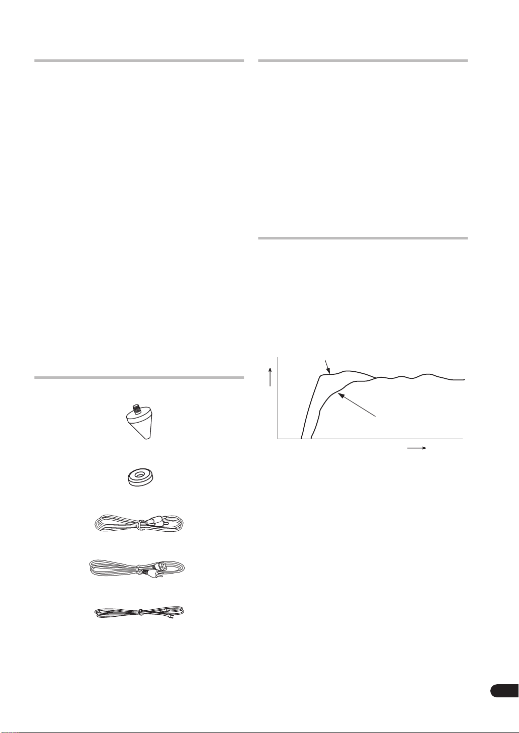
IN COMBINATION WITH
SPEAKERS
The frequency characteristics of the S-W1EX combined
with small-size speakers are shown below. As shown in
these figures, the low frequency range is improved.
• These special characteristics are obtained in an
echoless chamber. The effect of an additional SW1EX in an ordinary listening room is better than the
chart indicates when positioned adequately.
Small-size speakers + S-W1EX
ACCESSORY ITEMS
Spikes x 4
Bases x 4
RCA plug cord x 1
Power cable x 1
Ground cord x 1
Operating instructions x 1
Small-size speaker
RESPONCE (dB)
• With playback of Dolby* Digital, establishment of a
special channel for the subwoofer is recommended;
and with playback of LFE (Low Frequency Effect:
sound effect like the rumbling of the earth, whose
purpose is to intensify the force of the video), the SW1EX is especially effective.
Dolby* Digital
Dolby Digital is the name of the Dolby Surround multichannel digital system that was developed from Dolby
Surround, as a continuation of Dolby Pro Logic
Surround.
Dolby Digital is also referred to as a 5.1 channel system.
This is because it has 5 channels in the 20Hz – 20kHz
frequency range (front left and right, center, and rear left
and right) and an independent channel for the
subwoofer. The subwoofer channel is also referred to as
LFE (Low Frequency Effect).
The LFE channel is used according to individual tastes to
enhance the bass effect.
FREQUENCY (Hz)
En
3
Page 4
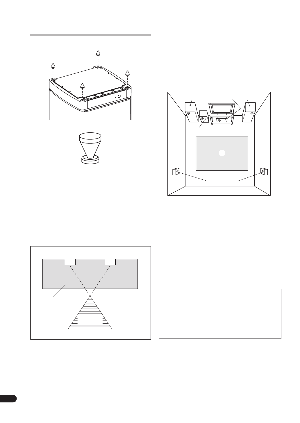
INSTALLATION
Before using this subwoofer, screw the 4 provided
decoupling spikes. If desired (especially with polished
wood floors), you can amploy the 4 provided metal bases
between the decoupling spikes and the floor.
An example of speaker positioning (ıııı)
•
11
Front left speaker
11
22
Center speaker
22
33
Front right speaker
33
44
Subwoofer
44
55
Listening area
55
66
Rear left speaker
66
77
Rear right speaker
77
1
2
4
5
67
3
Speaker Installation
• Subwoofer Installation Criteria (ÅÅÅÅ)
11
Left speaker
11
22
Right speaker
22
33
Recommended installation range for the
33
subwoofer
44
Listening position
44
11
11
33
33
44
44
The subwoofer plays back the bass in monaural, making
use of the fact that the human ear is not very sensitive to
the direction of low-pitched sound. Because of this, the
subwoofer can be installed almost anywhere. If it is
installed too far away, however, the sound from the other
speakers may become unnatural.
22
22
NOTE:
• To avoid interference with the picture on a nearby TV
set, use magnetically shielded speaker systems. This
is particularly important for the center speaker since
it is usually located closest to the TV.
• Position the left and right channel speakers at equal
distances from the TV set and approximately 1.8
meters from each other.
• Install the center speaker above or below the TV so
that the sound of the center channel is localized at
the TV screen.
• The rear (surround) speakers are most effective when
installed in parallel locations directly to the side, or
slightly behind, the listener, at a level about 1 meter
above the listener's ears.
CAUTION:
When installing the center speaker on top of the TV,
be sure to secure it with tape or some other suitable
means.
Otherwise, the speaker may fall from the TV due to
external shocks such as earthquakes, and it may lead
to endangering those nearby or damaging the
speaker.
4
En
Page 5
Installation Precautions
• Install the unit in a well-ventilated location where it
will not be exposed to high temperatures and high
humidity.
• Do not place the unit near stoves or other heating
equipment or at locations exposed to direct sunlight,
as these can have an adverse effect on the cabinet
and internal components. Also, do not install the unit
where there is too much dust or high humidity, as
these can cause malfunctioning or breakdowns.
(Avoid cooking tables and other locations where the
unit would be exposed to heat, steam and soot.)
• Do not place heavy objects such as a television or TV
monitor on top of the unit.
• Keep the unit away from devices such as cassette
decks which are sensitive to magnetic fields.
This speaker system is magnetically shielded.
However, depending on the installation location,
color distortion may occur if the speaker system is
installed extremely close to the screen of a television
set.
If this happens, turn off the power switch of the
television set, and turn it on after 15 to 30 minutes.
If the problem persists, place the speaker system
away from the television set.
• Please install this unit away from the antenna cable
of the tuner, as noise can be caused with installation
close to the antenna cable. In such a case, use this
unit at a position away from the antenna and the
antenna cable, or when playback of extra bass is not
required, switch off the power for this unit.
MAINTENANCE OF EXTERNAL SURFACES
• Use a polishing cloth or dry cloth to wipe off dust
and dirt.
• When the surfaces are very dirty, wipe with a soft
cloth dipped in some neutral cleanser diluted five
or six times with water, and wrung out well, and
then wipe again with a dry cloth. Do not use
furniture wax or cleaners.
• Never use thinners, benzine, insecticide sprays
and other chemicals on or near this unit, since
these will corrode the surfaces.
PANEL FACILITIES
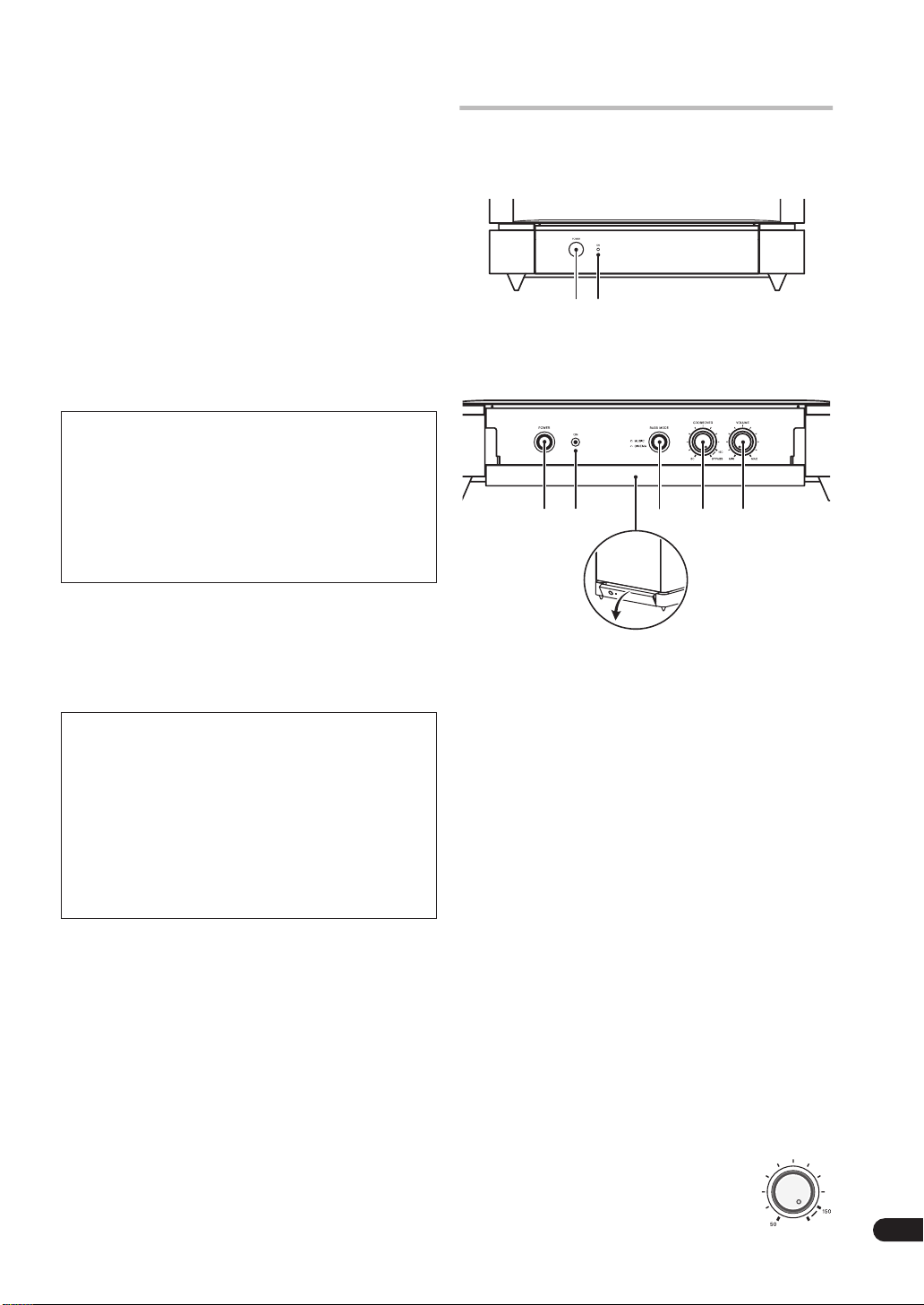
FRONT PANEL
21
The condition of closed door
12 3 4 5
Open the door.
1111Power switch (POWER)
When pressed, power is turned ON; when pressed again,
power is turned OFF.
22
Power Indicator (ON)
22
Illuminates when the power is on.
33
Bass mode switch (BASS MODE)
33
—
MUSIC
Recommended for music sources.
_
Recommended for sources that require strong bass.
44
Crossover knob (CROSSOVER) & Bypass switch
44
(BYPASS)
When using the subwoofer, set the upper frequency
limit for the subwoofer (
complemets the output from your other speakers.
When using the bass managment features of an AV
receiver, set to
filter of the AV receiver for high quality sound.
• Setting Criteria
50Hz
100Hz
150Hz
* When set to
routed directly to the woofer unit,
bypassing the amplifier's filter.
: The characteristic frequencies become flat.
CINEMA
: Low frequencies are emphasized.
50–150Hz
BYPASS
.......when the diameter of the left/right speakers
is 20-cm or more.
.....when the diameter of the left/right speakers
is 10 – 25-cm.
.....when the diameter of the left/right speakers
is 12-cm or less.
BYPASS
in order to use the low-pass
, the audio signal is
) so that it
CROSSOVER
BYPASS
5
En
Page 6
5555Volume knob (VOLUME)
Sets the subwoofer volume.
• Turn the knob slowly from the MIN position.
• With this unit, the bass level can be independently
set, so do not turn up the bass on the stereo or AV
amplifier.
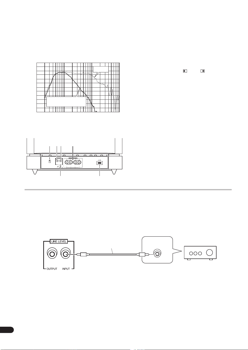
S-W1EX Music mode Frequency response
100
90
80
70
60
50
Sound pressure level (dB)
40
10
Non-bypass
(Crossover 150Hz)
100
Frequency (Hz)
Bypass
1000
REAR PANEL
867
0
10000
6666Line Level Input terminal (LINE LEVEL INPUT)
Connects to the stereo amplifier’s SUBWOOFER PREOUT terminal, with the specially provided RCA plug cord.
77
Line Level Output terminal (LINE LEVEL OUTPUT)
77
Used for connecting other equipment through the
amplifier. The signal output from this jack is not affected
in any way by the settings of the various controls on the
unit.
88
Phase switch (PHASE 0º /180º )
88
When set to
of the input signal, and when set to
180º
the output phase becomes the reverse
0º
it is in the same
phase as the input signal.
0º
• Normally, the switch is set to
.
But when the sound connection between the
subwoofer and the left and right speakers sounds
unnatural, try switching to
180º
• When using two or more subwoofers together, make
sure that the phase switch of all of them are set to the
same position.
99
Earth terminal
99
See
Connecting the signal ground terminal
00
Speaker Level Input terminals
00
on page 8.
(SPEAKER LEVEL INPUT)
Connect to the speakers output terminals on the stereo
amplifier, using speaker cords (not supplied).
--
Power supply cable connector
--
Connect the accessory power supply cable here.
9
-
CONNECTIONS
Before making or changing any connections, switch
off the power and disconnect both this unit and the
amplifier/receiver from the AC outlet.
LINE LEVEL CONNECTION (
S-W1EX(Rear Panel)
This connection is for a stereo amplifier or receiver
equipped with a
stereo amplifier or receiver is not equipped with a
SUBWOOFER PRE-OUT
Level connection. Connect to the
terminal on this unit, using the specially provided RCA
plug cord.
SUBWOOFER PRE-OUT
terminal, carry out a Speaker
ÅÅ
)
ÅÅ
Supplied RCA plug cord
terminal. If the
LINE LEVEL INPUT
SUB WOOFER
PREOUT
NOTES:
• When connected to the
PRE-OUT
terminal for
surround center channel on the stereo amplifier or
receiver, the bass is heard only on the center
channel, so it will be insufficient.
6
En
Page 7

SPEAKER LEVEL CONNECTION (
T
ıı
ıı
)
This is a connection to the speaker terminals on the
stereo amplifier or receiver.
Amplifier's or Receiver's SPEAKERS terminals
Connect speaker
cords 2 at a time.
Speaker cordsTo right speaker
+
To left speaker
system
_
_
system
R
+
+
_
S-W1EX
L
_
+
NOTES:
• When the power of the stereo amplifier is turned off
before the power of this unit is switched off, a shock
sound may be generated. In this case, lower the
subwoofer volume or turn off the power of this unit. If
the stereo amplifier has a switched outlet, connect
the power cable of this unit to this outlet.
• When the subwoofer volume is set to an extremely
high level, howling may be caused when the power of
the stereo amplifier is turned off or when the speaker
switch is turned on. To prevent this, lower the
subwoofer volume or turn off the power of this unit
before turning off the power of the stereo amplifier.
Also, when using this unit at a high level, do not turn
off the speaker switch of the stereo amplifier.
• Do not turn up the bass on the stereo amplifier or
receiver. If the stereo amplifier or receiver has no
output margin, sound distortion is apt to occur.
Adjust the bass level with the unit’s
• When the
the
LINE LEVEL INPUT
SPEAKER LEVEL INPUT
terminal is connected,
terminals cannot be
VOLUME
knob.
used.
Stereo amplifier or Receiver
R L
Right Speaker system Left speaker system
_
+
S-W1EX
Supplied AC power cord
_
+
To AC socket
Connect the unit to the stereo amplifier's or receiver's
speaker terminals at the same time the left and right
speakers are connected.
1. Use two sets of speaker cords (not supplied) to
connect the Right speaker system and the
LEVEL INPUT R
of the S-W1EX to the right speaker
SPEAKER
terminals of the stereo amplifier/ receiver. Do the same
for Left speaker system.
L (+
• Make sure
), L (–), R (+), R (–) are correctly
aligned.
NOTE:
• If the stereo amplifier or receiver has 2 sets of speaker
terminals (A, B) and these are connected to empty
terminals on the unit and “A + B” is selected with the
speaker switch, sound may not come out of the left/
right speakers, depending on the stereo amplifier or
receiver being used (a stereo amplifier or receiver is
constructed so that, when “A + B” is selected with
the speaker switch, A and B are in series
connection).
CAUTION
hese speaker terminals can be under HAZARDOUS
VOLTAGE. When you connect or disconnect the
speaker cables, to prevent the risk of electric shock, do
not touch uninsulated parts before disconnecting the
power cord.
D3-4-2-2-3_En
7
En
Page 8

Connecting the signal ground terminal
R
T
SUB
WOOFER
L
If you connect the line level input jack then do not connect the signal ground terminal.
• If you notice ground hum when the speakers are connected connect the supplied ground cord between the signal
ground terminal and the receiver/amplifier. (See diagram AA
• If there is no signal ground terminal on your receiver/amplifier, you can use one of the screws on the rear panel of
BB
the receiver/amplifier. (See diagram BB
below.)
A B
AUDIO
VIDEO
VIDEO S2 VIDEO
LR
DVD
IN
RF IN
(AC-3)
OUT
PCM/ /DTS /MPEG
DIGITAL
IN4
IN5
IN3
IN2
IN
1
PREOUT
SURR-
OUND
R
L
FRONT
OUT
2
1
R
L
CENTER
SUB
WOOFER
PLAY
TAPE2
MONITOR
REC
CD
IN
LINE/
TUNER
IN
LR
AUDIO
MULTI CH IN
WOOFER
/LD
IN
TV/
SAT/
IN
DVD
IN
L
IN
IN
VCR1
FRONT
/DVR
OUT
R
L
SURR OUND
R
CENTER
SUB
OUT
IN
IN
VCR2
OUT
OUT
PLAY
MONITOR
OUT1
MD/
TAPE1
/CD-R
REC
MONITOR
PHONO
OUT2
IN
IN
OUT
CONTROL
AA
below.)
AL IN
/DTS
(CD) (CD-R)
OPT OPT OPT
DIGITAL
OUT
FRONT FRONTSURROUNDCENTER
COMPONENT
VIDEO
TO MONITOR TV OUT
B/PB CR/PR YCB/PB CR/PR
YC
SPEAKERS
CENTER
PREOUT
(DVD/LD) IN
(TV/SAT) IN
OPERATION
For details regarding operating part functions, refer to
page 5.
1. Turn the POWER switch 1111ON.
• If the unit’s power cord is connected to a switched
AC outlet on the stereo amplifier or receiver and the
switch is left ON, the unit can be turned ON/OFF
together with the stereo amplifier or receiver.
• If the unit cannot be connected to the stereo
amplifier or receiver, turn the power to the stereo
amplifier or receiver ON before turning the power to
the unit ON. When turning the power OFF, turn the
power to the unit OFF before turning the power to the
stereo amplifier or receiver OFF.
2. Operate the stereo amplifier or receiver and
adjust the volume of the other speakers.
3. Adjust the volume of the bass with the VOLUME
55
knob 55
.
8
En
• When necessary, operate the
PHASE
and
VOLUME
either
switch 8888, and then adjust with the
knob 5555. Set the
MUSIC
or
CINEMA
BASS MODE
.
CROSSOVER
switch 3333 to
knob 4444
Page 9

TROUBLESHOOTING
Incorrect operations are often mistaken for trouble and malfunctions. If you think that there is something wrong with
this component, check the points below. Sometimes the trouble may lie in another component. Investigate the other
components and electrical appliances being used If the trouble cannot be rectified even after exercising the checks
listed below, ask your nearest PIONEER authorized service center or your dealer to carry out repair work.
SYMPTOM
11
11
No power is being supplied
(Indicator does not light up when
power switch is turned on.)
22
22
No sound
(Indicator is lit.)
33
Sound is weak.
33
(VOLUME knob is turned up.)
44
44
Sound is distorted.
55
Howling noise occurs.
55
66
Much noise when listening to
66
AM or FM broadcasts.
• Power supply plug is not
correctly inserted.
• Connection of speaker or
accessory RCA plug cord is
wrong or disconnected.
VOLUME knob is set to MIN .
•
• Polarity of the speaker cords
(from the amplifier or receiver to
this unit) is reversed.
• Level is too high.
• Input level is too high.
• Power supply to amplifier or
speaker switch is turned off.
• Subwoofer level is set too high.
• The AM loop antenna or the FM
indoor antenna is close to this
unit.
CAUSE REMEDY
• Insert plug securely.
• Check again and connect correctly.
• Turn clockwise slowly.
• Confirm the polarity of the wires and
connect them correctly.
• Turn the VOLUME knob counterclockwise to lower the level.
• Turn the amplifier’s output level
(volume, bass control, bass boost)
counter-clockwise to lower the level.
• Connect power supply to amplifier and
turn speaker switch on.
• Place the subwoofer a good distance
from speakers. Turn the
counter-clockwise to lower the volume.
• Increase the distance between the AM
or FM antenna (for indoor use) and this
unit.
VOLUME knob
SPECIFICATIONS
Cabinet ............ Floor type with PASSIVE RADIATOR system
Woofer ............................................................30 cm cone type
PASSIVE RADIATOR......................................30 cm cone type
Frequency response .................25 – 4,000Hz(set to BYPASS)
Power Amplifier Continuous Power Output (RMS)
.................................................................. 250 W/4 Ω (100 Hz)
・・
Above specifications are for when power supply is 230 V.
・・
Input (sensitivity at 100 Hz/impedance)
SPEAKER LEVEL...................................1.6 V + 1.6 V/15 k Ω
(both channels in-phase)
LINE LEVEL (RCA jack)....................................160 mV/50 k Ω
Output (Level at 100 Hz/impedance)
LINE LEVEL (RCA jack)......................................160 mV/1 k Ω
CROSSOVER Frequency
......................................... 50 – 150 Hz (continuously variable)
Outline Dimension............430 (W) x 480 (H) x 430 (D) mm
Weight (without package).............................................34.5 kg
Power Requirements......................... 220 – 230 V~, 50/60 Hz
Power Consumption.........................................................56 W
(Magnetically shielded)
Accessories.............................................................Spikes x 4
Operating instructions x 1
Bases x 4
RCA plug cord x 1
Power cable x 1
Ground cord x 1
NOTE:
Specifications and design subject to possible
modification without notice, due to improvements.
Published by Pioneer Corporation.
Copyright © 2005 Pioneer Corporation.
All rights reserved
is a trademark placed on a product with
Pioneer’s Phase Control Technology.
The Technology enables high-grade 5.1ch
with no delay in the bass area.
9
En
Page 10

25 15 10
Page 11

目錄
配件
....................................................3
功能與特色
結合揚聲器運用
安裝
....................................................4
揚聲器安裝
安裝注意事項 ...................................... 5
面板設備
前面板
後面板
....................................................6
接線
線路位準接線 (
揚聲器位準接線 (
連接信號接地端子
....................................................8
操作
故障排除
....................................................9
規格
.........................................3
..................................3
.......................................... 4
.............................................5
.................................................. 5
.................................................. 6
ÅÅ
ÅÅ
.......................... 6
)
ıı
ıı
...................... 7
)
...............................8
.............................................9
功能與特色
(
7
250W
Dolby* Digital
體播放。
搭配
7
可以連續輸出的轉化頻率 (
7
(
50 – 150Hz, & Bypass
具備低音模式選擇器 (音樂劇院模式)。
7
7
2
子的輸入,以及一組可 連接至
(重低音前置輸出)端子的輸入所組成。
經
*
記號是
D
RMS
公分的音效驅動裝置 (
30
組系統,主要是由一組可連接至擴大器之揚聲器端
Dolby Laboratories
Dolby Laboratories
)高功率
此種具有寬廣動態範圍的音頻及視頻軟
級擴大器,能提供如同
D
)。
driver
Turnover frequency
)。
SUBWOOFER PRE-OUT
授權製造。「杜比」「
的商標。
Dolby
結合揚聲器運用
結合了小型揚聲器的
如圖中所示,低頻範圍明顯獲得改善。
這些獨特的特性均是在無迴音室內所測得的結果。
•
只要安放的位置妥當,在一般聆聽室內加裝
重低音,便可以產生比圖表顯示更棒的效果。
小型揚聲器
S-W1EX
+ S-W1EX
其頻率特性如下圖所示。
)
」與雙
S-W1EX
配件
RCA
耦合釘
釘墊
插頭連接線
電源線
接地線
操作手冊
)
dB
響應(
×
4
×
4
1
×
1
×
×
1
×
1
在播放
•
Dolby* Digital
Dolby Digital
的
Dolby Surround
Pro Logic Surround
Dolby Digital
擁有頻率範圍在
左前置、右前置、中置、左後置以及右後置)以及一重低
音的獨立聲道。重低音聲道亦可視為是一種
效果)。
此種
Dolby* Digital
重低音來建立效果特殊的聲道;而在播放
(低頻效果:此種 音效 有如 來自 地表 的隆隆聲,功
用在於加強影像所帶來的震撼力)時,
音能讓效果更具震撼有力。
指的是自
多聲道數位系統的名稱,亦即是
的延續。
亦可視為是一種
20Hz – 20kHz
聲道的使用可根據個人品味來加強低音效果。
LFE
小型揚聲器
頻率(
Hz
)
杜比數位音效時,建議您採用
LFE
S-W1EX
Dolby Surround
5.1
內的五種聲道 (分別是
中所開發出來
聲道系統。這是因其
LFE
音效
重低
Dolby
(低頻
ChH
3
Page 12

安裝
揚聲器安裝位置之範例 (
•
左前置揚聲器
11
11
22
22
中置揚聲器
33
33
右前置揚聲器
44
44
重低音揚聲器
55
55
聆聽位置
66
66
左後置揚聲器
77
77
右後置揚聲器
1
4
ıı
ıı
)
2
3
使用重低音之前,請先將附贈的四只耦合釘裝上。如有需
要(特別將地板打亮),您可以將附贈的四只金屬釘墊裝
在耦合釘與地板之間的地方。
揚聲器安裝
11
11
ÅÅ
ÅÅ
)
44
44
22
22
重低音安裝標準 (
•
11
左置揚聲器
11
22
右置揚聲器
22
33
重低音建議安裝距離
33
44
聆聽位置
44
33
33
5
67
附註:
為了能夠避免干擾附近的電視畫面,請採用經過防磁
•
處理(
magnetically shielded
揚聲器位置通常最接近電視機,因此這點相當重要。
請將左聲道與右聲道的揚聲器擺在電視機兩側距離
•
相同的位置上,同時彼此應相距
請將中置揚聲器安裝在電視機的上方或下方,如此才
•
能讓中置聲道的音效彷如就從電視畫面傳出來一樣。
當將後置(環繞)揚聲器直接相互平行地置放在聆聽
•
者的兩側,或稍微後方一點的位置,高度大約在聆聽
者耳朵上方一公尺的地方,這會是最有效果的安裝方
式。
注意:
當要將中置揚聲器安裝在電視機上方,請確實利用膠
帶或其他一些合適的方式將其固定。
不然,揚聲器可能會因為受到地震等外力震動而掉落
下來,導致附近的人受傷或揚聲器因此而受損。
)的揚聲器系統。中置
公尺。
1.8
4
ChH
重低音是透過單聲 道的方式 來播放低音,實際 上人類耳
朵對於低調(
敏感。也因此,重低 音幾 乎可 以安裝 在任何 地方。然
而,如果安裝位置相距 太遠,其他揚 聲器的音 效亦可能
會變得不自然。
low-pitched
)音效傳來的 方向不會太過
Page 13

安裝注意事項
請將本機安裝在溫度及濕度不致過高且通風良好的
•
地方。
請勿將本機擺放在烤箱或其他加熱設備附近,或陽光
•
會直射到的地方,以免對外箱及內部零件造成不利影
響。另外,請勿將本機安裝在灰塵太多或濕氣太重的
地方,以免功能異常或發生故障。(請避免將本機安
放在餐桌上或其他暴露在熱氣、蒸汽及油煙下的地
方。)
請勿將電視機或電視監視器等重物直接置於本機上。
•
請儘量避免將本機放在錄音機座等對磁場敏感設備
•
的附近。
本揚聲器系統採防磁處理。
然而,仍需視安裝的位置而定,揚聲器系統如安裝得
太過靠近電視機螢幕時可能會造成色彩失真。
如果發生這種現象,請按下電源開關將電視機關閉,
然後過
如果問題仍在,請將揚聲器系統遠離電視機擺放。
請將本機遠離調諧器天線擺放,以免安裝位置大過接
•
近天線而產生雜音。此時,使用本機請遠離天線,或
在不需要播放重低音時關閉本機電源。
15–30
分鐘後再打開。
面板設備
前面板
翻蓋關上時
21
12 3 4 5
外觀保養
請用細布或乾布將塵土擦拭乾淨。
•
外表很髒時,請用軟布沾上一些五倍清水稀釋的中
•
性清潔劑澈底擰乾後擦拭,接著以乾布再擦拭一
次。請勿使用傢俱蠟或清潔劑。
嚴禁在本機上面或其附近使用稀釋劑、揮發油、除
•
蟲噴劑或其他化學物品,以免腐蝕表面。
掀開翻蓋。
11
11
電源開關 (
按下此鍵可打開電源;再按時,則可關閉電源。
電源指示燈 (
22
22
亮起時為表示電源已開。
低音模式開關 (
33
33
—
MUSIC
於音樂來源。
CINEMA
_
有需求的來源。
分頻旋鈕 (
44
44
(
BYPASS
使用重低音時,請設定好頻率上限 (
便能夠補償其他揚聲器的輸出。當使用到影音接收機的
低音管理功能,請將其設定為
用影音接收機的低通濾波器(
音效品質。
設定標準
•
50Hz ........
100Hz ......
150Hz ......
設定在
*
至低音揚聲器上,而略過擴大器的濾波
裝置。
POWER
)
)
ON
BASS MODE
:特性頻率均會呈現較低的狀態。建議可用
)
:低階頻率會加強。建議可 用在對重 低音
CROSSOVER
)
)及略過濾波開關
50–150Hz
,以便有機會使
BYPASS
low-pass filter
)來提高
當左右置揚聲器的直徑為
當左右置揚聲器的直徑為
當左右置揚聲器的直徑為
BYPASS
時,音頻信號會直接傳送
公分以上。
20
10 – 25
公分以下。
12
CROSSOVER
),以
公分。
BYPASS
5
ChH
Page 14

音量調整鈕 (
(後面板)
55
55
可設定重低音的音量。
請從最低音量 (
•
對於本機而言,低音位準可單獨調整,因此請勿調高
•
音響或影音擴大器上的低音音量。
100
90
80
70
60
音壓位準(dB)
50
40
10
VOLUME
(150Hz分頻)
)
)的位置慢慢轉動旋鈕。
MIN
S-W1EX音樂模式頻率響應
未濾波
濾波頻率
100
頻率(Hz)
1000
10000
)
180º
乙節。
。
)
)
線路位準輸入端子 (
66
66
可利用特別附贈的
SUBWOOFER PREOUT
線路位準輸出端子 (
77
77
用於透過擴大器來連接 其他設備。此插孔 的信號輸 出可
藉由本機上各種控制的設定讓其不會受到任何影響。
相位開關 (
88
88
設定為
而設定為
一般來說,此開關會設定在
•
但當重低音與左、右置揚聲器之間的音效連結呈現出
不自然的情形時,請嘗試切換至
當將兩只以上的重低音一起使用,請確定這些重低音
•
的相位開關均設定在相同的位置。
接地端子
99
99
請參閱第
PHASE 0º /180º
時,輸出的相位會呈現出與輸入信號反向,
180º
時,則會呈現出與輸入信號同向。
0º
頁
“連接信號接地端子”
8
LINE LEVEL INPUT
插頭連接線來連接音響擴大器的
RCA
(重低音前置輸出)端子。
LINE LEVEL OUTPUT
的位置。
0º
後面板
867
9
0
-
接線
進行或變更任何接線之前,請先關閉電源,並拔除
座上本機及擴大器接收機的連接線。
ÅÅ
線路位準接線 (
S-W1EX
ÅÅ
)
附贈的RCA插頭連接線
AC
揚聲器位準輸入端子
00
00
(
SPEAKER LEVEL INPUT
可利用揚聲器連接線來連接 至音響擴 大器上的揚聲 器輸
出端子。
電源線接頭
--
--
可將隨附的電源線連接於此。
插
重低音
前置輸出
)
6
ChH
此種接線方式適用 於配備重低音 前置輸出端子 的音響擴
大器或接收機。如果音 響擴大器 或接收機上未 配備重低
音前置輸出端子,請改採揚聲器 位準接線 方式。請利用
特別附贈的
INPUT
RCA
(線路位準輸入)端子。
插頭連接線連至本機上的
LINE LEVEL
附註:
•
在連接至音響擴大器或接收機上專為提供環繞中置
聲道的前置輸 出 (
聲道聽到低音效果,以這樣來說效果是不夠的。
PRE-OUT
)端子時,只能從 中置
Page 15

揚聲器位準接線 (
ıı
ıı
)
這是一種接至音響擴大器或接收器上的接線方式。
擴大器或接收器之揚聲器端子
R
+
+
_
至右置揚聲器
系統
附註:
先關閉音響擴大器的電源,然後再關閉本機電源時,
•
便會產生震音 (
shock sound
_
S-W1EX
L
_
+
)。此時,請調低重低
同一時間接上
兩條揚聲器連接線
揚聲器連接線
+
至左置揚聲器
系統
_
音的音量或關閉本機電源。如果音響擴大器上有開關
式輸出插座,則請將本機的電源連接至此輸出插座
上。
當重低音音量設定得相當高,而在關閉音響擴大器的
•
電源或打開揚聲器開關時,會發出咆哮聲。為了避免
此種情形,請在關閉音響擴大器電源之前先行調低重
低音音量或關閉本機電源。另外,在高音量下使用本
機時,請勿關閉音響擴大器上的揚聲器開關。
請勿調高音響擴大器或接收機上的低音音量。如果
•
音響擴大器或接收機未設定 輸出 限制,則可能 會產
生音效失真的 現象。請利用 本機上的 音量
(
VOLUME
在
•
LINE LEVEL INPUT
SPEAKER LEVEL INPUT
)調整鈕來調整低音位準。
端子接上時,便不能使用
端子。
音響擴大器或接收機
R L
右置揚聲器系統 左置揚聲器系統
_
+
S-W1EX
附贈
AC電源線
_
+
至AC插座
請在接上左置及右置揚 聲器的同時,將本 機連接至 音響
擴大器或接收機上的揚聲器端子。
請使用兩組揚聲器線
1.
聲器系統及
SPEAKER LEVEL INPUT R
(
未附
來連接
)
S- W1EX
至立體聲擴大器
的右揚
/
接收機的右揚聲器端子 上。請以相同方式 來連接左 揚聲
器系統。
確實正確對照
•
附註:
如果音響擴大器或接收機有兩組揚聲器端子 (
•
),而這些端子 又連接至本機 上的未用 端子,同時
B
又以揚聲器開關選擇了 “
L ( +
、
、
、
)
)
L ( –
)
R ( +
”,則所聽到的音效
A + B
R ( –
)
端子接上。
、
A
便不像是來自左右置揚聲器,這須視所使用的音響
擴大器或接收機而定(有一音響擴大器或接收機的結
構,即是在利用揚聲器開關選擇了 “
與
A
B
為串接在一起)。
將
A + B
”時,會
注意
這些揚聲器端子均是處於「危險有電」的狀態。為了避
免電擊危險,要接上或拔除這些揚聲器連接線時,未先
拔除電源線前請勿觸摸未絕緣的零件。
D3-4-2-2-3_ChH
ChH
7
Page 16

連接信號接地端子
R
SUB
WOOFER
L
如果您連接了線路位準輸入插孔,那麼請勿連接信號接地端子。
如果您注意到在接上揚聲器時出現地線雜音 (
•
上隨機附贈的接地線。(如下方圖
如果您的接收機擴大器上沒有信號接地端子,那麼您可以 利用接收機擴大器後面板上的其中一個 螺絲。(如
•
下方圖
所示。)
BB
BB
所示。)
AA
AA
ground hum
A B
AUDIO
VIDEO
VIDEO S2 VIDEO
LR
DVD
IN
RF IN
(AC-3)
OUT
PCM/ /DTS /MPEG
DIGITAL
IN4
IN5
IN3
IN2
IN
1
PREOUT
SURR-
OUND
R
L
FRONT
OUT
2
1
R
L
CENTER
SUB
WOOFER
PLAY
TAPE2
MONITOR
REC
CD
IN
LINE/
TUNER
IN
LR
AUDIO
MULTI CH IN
WOOFER
/LD
IN
TV/
SAT/
IN
DVD
IN
L
IN
IN
VCR1
FRONT
/DVR
OUT
R
L
SURR OUND
R
CENTER
SUB
OUT
IN
IN
VCR2
OUT
OUT
PLAY
MONITOR
OUT1
MD/
TAPE1
/CD-R
IN
REC
OUT
MONITOR
PHONO
OUT2
IN
CONTROL
),那麼請在信號接地端子與接收機擴大器之間接
DIGITAL
AL IN
OUT
/DTS
(CD) (CD-R)
OPT OPT OPT
FRONT FRONTSURROUNDCENTER
COMPONENT
VIDEO
TO MONITOR TV OUT
B/PB CR/PR YCB/PB CR/PR
YC
SPEAKERS
CENTER
PREOUT
(DVD/LD) IN
(TV/SAT) IN
操作
有關操作功能部份的詳細說明請參閱第
將電源 (
1.
如果本機的電源線是連接至音響擴大器或接收機上
•
的開關式
POWER
輸出插座、且開關在
AC
)開關
11
11
打開 (
頁。
5
)。
ON
(開)的位置
ON
必要時,請操作分頻 (
•
(
調整鈕
定在
PHASE
MUSIC
55
55
)開關
。將低音模式 (
或
CINEMA
CROSSOVER
,然後再利用音量 (
88
88
BASS MODE
的位置。
時,那麼便可 將擴 大器或接收機與本機一起打開
關閉。
如果本機無法連接至音響擴大器或接收機上,那麼請
•
先打開音響擴大器或接收機,然後再打開本機電源。
在關閉電源時,請關閉本機電源,然後再關閉音響擴
大器或接收機電源。
操作音響擴大器或擴收機並調整其他揚聲器的音量。
2.
利用音量 (
3.
VOLUME
)調整鈕
55
調整低音的音量。
55
8
ChH
)鈕
)開關
及相位
44
44
VOLUME
33
33
)
設
Page 17

人們經常錯將操作不當認為是系統故障或異常。如果您覺得本機有那裏不對勁,便請按以下各點進行檢查。有時問題
可能是來自其他裝置。請仔細檢查其他使用中的裝置和電器設備。如果在查證過以下各點後問題仍未改善,則就近洽
請您的
PIONEER
沒有電源供應
11
11
(指示燈在轉開電源開關時沒亮。)
沒有聲音
22
22
(指示燈亮。)
33
33
聲音微弱。
(
(音 量
高。)
44
44
聲音失真。
授權服務中心或經銷商前來維修。
癥狀 原因 排除辦法
•
電源插頭未正確插好。
•
確實將插頭插好。
VOLUME
)
調整鈕已調
•
揚聲器或附贈的
線連接錯誤或已被拔除。
•
音量 (
VOLUME
在最低音量 (
揚聲器線的極性(由擴大器或接
•
收機至本機)顛倒。
位準太高。
•
輸入位準太高。
•
RCA
)調整 鈕 設定
MIN
插頭連接
)的位置。
•
請再檢查一次並正確接上。
•
順時針慢慢轉動。
確認揚聲器線的極性並正確接上。
•
反時針轉動音量 (
•
降低位準。
反時針轉動擴大器的輸 出位準 (音量、
•
VOLUME
)調整鈕以
低音控制、低音加重)以降低位準。
發出咆哮聲。
55
55
•
通至擴大器的電源或電源開關
已關閉。
•
重低音位準設定太高。
•
將電源接至擴大器上並打開揚聲器開關。
•
將重低音放在與揚聲器距離 適當的位置
上。反時針轉動音量 (
VOLUME
)調整
鈕以降低音量。
66
66
聆聽 AM或 FM廣播時雜音太
多。
環型天線或
•
AM
本機太過接近。
室內天線與
FM
增加
•
間的距離。
AM
或
天線(室內用)與本機之
FM
規格
................................
外箱
低音揚聲器
被動式擴散器
頻率響應
功率擴大器持續功率輸出 (
......................................... 30
...................................... 30
.............................25
....................................................250 W/4
•
上述規格為適用於
100 Hz
輸入 (
揚聲器位準
(兩個聲道為同相位)
線路位準 (
輸出 (
線路位準 (
.................................. 50
分頻
外部尺寸
重量 (不含外包裝)
電源需求
功率消耗
阻抗下之靈敏度)
................................. 1.6 V + 1.6 V/15 k
RCA
插孔)
100 Hz
阻抗下之位準)
RCA
插孔)
..... 430
............................... 220
(寬)
.............................................................56 W
帶被動式擴散器的落地式系統
–
4000 Hz
RMS
)
230 V
電源。
........................ 160 mV/50 k
.......................... 160 mV/1 k
–
×
480
150 Hz
(高)
(會持續改變)
×
430
.......................................34.5
–
230 V
(磁屏蔽)
公分圓錐體型
公分圓錐體型
(設為忽略)
(100 Hz)
Ω
mm
(深)
公斤
~
, 50/60 Hz
............................................................
配件
RCA
附註:
規格與設計如因改良而有所變動時,恕不另行通知。
Ω
Ω
版權
Ω
2005
4
×
耦合釘
4
×
釘墊
×
插頭連接線
電源線
接地線
操作手冊
日本先鋒公司出版。
日本先鋒公司。
1
×
1
×
1
×
1
版權所有。
ChH
9
Page 18

日本先鋒公司出版。
版權
版權所有。
2005 日本先鋒公司。
©
<SRD6031-A>
 Loading...