

Page 1
En
1
Page 2
Location: underside of the unit
IMPORTANT
The lightning flash with arrowhead
symbol, within an equilateral
triangle, is intended to alert the
user to the presence of uninsulated
“dangerous voltage” within the
product's enclosure that may be of
sufficient magnitude to constitute
a risk of electric shock to persons.
CAUTION
RISK OF ELECTRIC SHOCK
DO NOT OPEN
CAUTION:
TO PREVENT THE RISK OF ELECTRIC
SHOCK, DO NOT REMOVE COVER
(OR BACK). NO USER-SERVICEABLE
PARTS INSIDE. REFER SERVICING
TO QUALIFIED SERVICE
PERSONNEL.
The exclamation point within an
equilateral triangle is intended to
alert the user to the presence of
important operating and
maintenance (servicing)
instructions in the literature
accompanying the appliance.
H002_En
WARNING:
WATERPROOF. TO PREVENT FIRE OR SHOCK
HAZARD, DO NOT EXPOSE THIS APPARATUS TO
RAIN OR MOISTURE AND DO NOT PUT ANY
WATER SOURCE NEAR THIS APPARATUS, SUCH
AS VASES, FLOWER POTS, COSMETICS
CONTAINERS, MEDICINE BOTTLES, ETC.
THIS APPARATUS IS NOT
CAUTION: The POWER switch does not
completely separates the unit from the MAINS
in off position. Therefore install the unit suitable
places easy to disconnect the MAINS plug in
case of the accident. The MAINS plug of unit
should be unplugged from the wall socket when
left unused for a long period of time.
H017B_En
WARNING: NO NAKED FLAME SOURCES,
SUCH AS LIGHTED CANDLE, SHOULD BE
PLACED ON THE APPARATUS. IF NAKED FLAME
SOURCES ACCIDENTALLY FALL DOWN, FIRE
SPREAD OVER THE APPARATUS THEN MAY
CAUSE FIRE.
H044_En
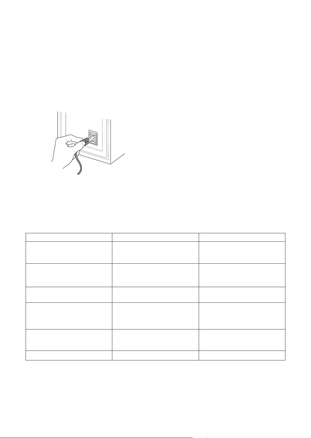
Power cable caution
Handle the power cable by the plug part. Do
not pull out the plug by tugging the cable, and
never touch the power cable when your hands
are wet, as this could cause a short circuit or
electric shock. Do not place the system unit, a
piece of furniture, or other object on the power
cable or pinch the cable in any other way.
Never make a knot in the cable or tie it with
other cables. The power cable should be
routed so that they are not likely to be stepped
on. A damaged power cable can cause a fire or
give you an electric shock. Check the power
cable once in a while. If you find it damaged,
ask your nearest Pioneer authorized service
center or your dealer for a replacement.
2
En
VENTILATION:
When installing this unit, make sure to
leave space around the unit for ventilation
to improve heat radiation (at least 25 cm at
top, 10 cm at rear, and 10 cm at each side).
WARNING: Slot and openings in the
cabinet are provided for ventilation and to
ensure reliable operation of the product
and to protect it from overheating, to
prevent fire hazard, the openings should
never be blocked and covered with items,
such as newspapers, table-cloths, curtains,
etc. Also do not put the apparatus on the
thick carpet, bed, sofa, or fabric having a
thick pile.
Operating Environment H045_En
Operating environment temperature and
humidity:
+5ºC – +35ºC (+41ºF – +95ºF); less than 85%RH
(cooling vents not blocked)
Do not install in the following locations
÷ Location exposed to direct sunlight or strong
÷ artificial light
÷ Location exposed to high humidity, or poorly
ventilated location
H040 En
Page 3
LINE VOLTAGE SELECTOR SWITCH
The line voltage selector switch is located on the
rear panel. Check that it is set properly before
plugging the power cord into the outlet. If the
voltage is not properly set or if you move to an
area where the voltage requirements differ, adjust
the selector switch as follows:
¶ Be sure to disconnect the power cord from its
outlet before making this adjustment.
¶ Use a medium-sized (flat blade) screwdriver.
Insert the tip of the screwdriver into the groove
of the selector switch and turn it so that the
power voltage marking of your area points to
the arrow.
240V
220-
V
230
110-
V
127
CONTENTS
FEATURES ................................. 4
ACCESSORY ITEMS.................. 4
BEFORE USE.............................. 4
CABINET MAINTENANCE ......... 4
INSTALLATION.......................... 5
Speaker Installation ................... 5
Installation Precautions............. 5
IN COMBINATION WITH
SPEAKERS ................................. 6
LINE LEVEL CONNECTION ....... 6
PANEL FACILITIES..................... 7
OPERATION ............................... 8
TROUBLESHOOTING................ 8
SPECIFICATIONS....................... 9
English
CAUTION 220 – 230 V
Power source voltage is factory adjusted
220 - 230 volts. If your area is different,
change voltage selectors settings.
H038 En
WARNING:
FOR THE FIRST TIME, READ THE FOLLOWING
SECTION CAREFULLY. THE VOLTAGE OF THE
AVAILABLE POWER SUPPLY DIFFERS
ACCORDING TO COUNTRY OR REGION. BE SURE
THAT THE POWER SUPPLY VOLTAGE OF THE
AREA WHERE THIS UNIT WILL BE USED MEETS
THE REQUIRED VOLTAGE (E.G., 230V OR 120V)
WRITTEN ON THE REAR PANEL.
BEFORE PLUGGING IN THE UNIT
H041A_En
En
3
Page 4
FEATURES
BEFORE USE
• 100 W power that serves video software playback such
as Dolby* Digital with a wide dynamic range.
• An input that connects to the SUBWOOFER PRE-OUT
terminal
Manufactured under license from Dolby Laboratories. “Dolby”
and the double-D symbol are trademarks of Dolby
Laboratories. Confidential unpublished works. © 1992-1997
Dolby Laboratories. All rights reserved.
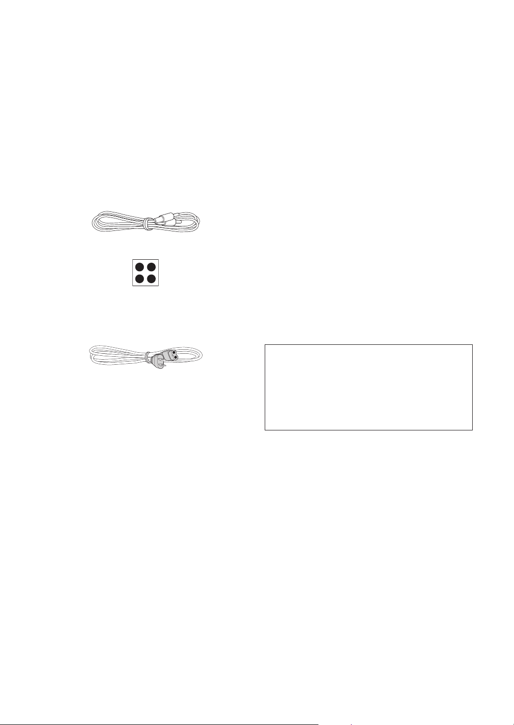
ACCESSORY ITEMS
RCA plug cord x 1
Non-slip pads (1x4)
(Stick one non-slip pad in each corner of the underside of
the subwoofer.)
Power cord
• Thank you for buying this Pioneer product.
• Please read this operating guide through before using
your speaker system so you will know how to optimize
performance. After you have finished reading the
operating guide, store it in a safe place for future
reference.
• The nominal impedance of this speaker system is 6 Ω.
Connect the speaker system to a stereo amplifier with a
load impedance ranging from 4 to 16 ohms (a model with
“4 – 16 Ω” displayed on the speaker output terminals).
• In order to prevent damage to the speaker system
resulting from input overload, please observe the
following precautions:
• Do not supply power to the speaker system in excess of
the maximum permissible input.
• When connecting or disconnecting pin-plugs, be sure
amplifier power is OFF.
• When using a graphic equalizer to emphasize loud
sounds over a high-frequency range, do not use
excessive amplifier volume.
• Do not try to force a low-powered amplifier to produce
loud volumes of sound (the amplifier’s harmonic
distortion will be increased, and you may damage the
speaker).
• Do not touch the speaker cone’s reverberating surfaces
as they may be damaged by external force.
This Subwoofer are magnetically shielded.
However,depending on the installation location,color
distortion may occur if the speaker system is installed
extremely close to the screen off a television set.
If this happenscase,turn of the power switch of the
television set OFF,and turn it on after 15 to 30
minutes.If the problem persists,place the speaker
system away from the television set.
4
En
CABINET MAINTENANCE
• Use a polishing cloth or dry cloth to wipe off dust and
dirt.
• When the cabinet is very dirty, clean with a soft cloth
dipped in some neutral cleanser diluted five or six times
with water, and then wipe again with a dry cloth. Do not
use furniture wax or cleaners.
• Never use thinners, benzine, insecticide sprays and
other chemicals on or near the cabinets, since these will
corrode the surfaces.
Page 5
English
INSTALLATION
AB
4
1
2
2
1
3
7
5
3
6
4
Speaker Installation
The subwoofer plays back the bass in monaural, making
use of the fact that the human ear loses the sense of
direction of low-pitched sound. Since the sense of direction
is lost, the subwoofer can be installed almost anywhere. If
it is installed too far away, however, the sound from the left
and right speakers may become unnatural.
CAUTION:
When installing the center speaker on top of the TV, be sure
to secure it with tape or some other suitable means.
Otherwise, the speaker may fall from the TV due to external
shocks such as earthquakes, and it may lead to endangering
those nearby or damaging the speaker.
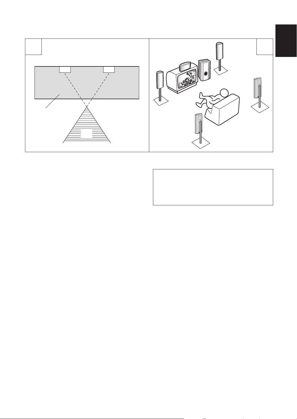
Subwoofer Installation Criteria (Å)
1 Left speaker
2 Right speaker
3 Recommended installation range for the subwoofer
4 Listening position
An example of speaker positioning (ı)
1 Front left speaker
2 Center speaker
3 Front right speaker
4 Subwoofer
5 Listening area
6 Surround speaker left
7 Surround speaker right
NOTE:
• Position the left and right channel speakers at equal distances
from the TV set.
• Install the center speakers above or below the TV so that the
sound of the center channel is localized at the TV screen.
• The rear (surround) speakers are most effective when installed
in parallel locations directly to the side, or slightly behind, the
listener, at a level about 1 meter above the listener's ears.
Installation Precautions
• Install the unit in a well-ventilated location where it will
not be exposed to high temperatures and high humidity.
• Do not place the unit near stoves or other heating
equipment or at locations exposed to direct sunlight, as
these can have an adverse effect on the cabinet and
internal components. Also, do not install the unit where
there is too much dust or high humidity, as these can
cause malfunctioning or breakdowns. (Avoid cooking
tables and other locations where the unit would be
exposed to heat, steam and soot.)
• Do not place heavy objects such as a television or TV
monitor on top of the unit.
• Keep the unit away from devices such as cassette decks
which are sensitive to magnetic fields
• Please install this unit away from the antenna cable of
the tuner, as noise can be caused with installation close
to the antenna cable. In such a case, use this unit at a
position away from the antenna and the antenna cable,
or when playback of extra bass is not required, switch off
the power for this unit.
5
En
Page 6
MAINTENANCE OF EXTERNAL
SURFACES
Use a polishing cloth or dry cloth to wipe off dust and dirt.
•
When the surfaces are very dirty, wipe with a soft cloth
•
dipped in some neutral cleanser diluted five or six times
with water, and wrung out well, and then wipe again with a
dry cloth. Do not use furniture wax or cleaners.
Never use thinners, benzine, insecticide sprays and other
•
chemicals on or near this unit, since these will corrode the
surfaces.
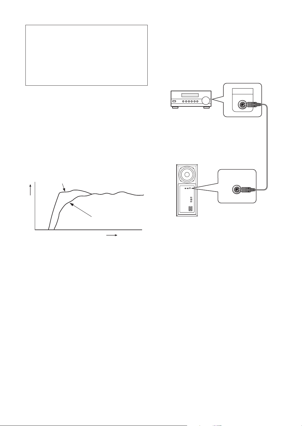
IN COMBINATION WITH
SPEAKERS
The frequency characteristics of the S-HS02 combined with
satellite speakers are shown below. As shown in these
figures, the low frequency range is improved.
• These special characteristics are obtained in an echoless
chamber. The effect of an additional subwoofer in an
ordinary listening room is better than the chart indicates
when positioned adequately.
Satellite speaker + Subwoofer
LINE LEVEL CONNECTION
Before making or changing the connections, switch off
the power switch and disconnect the power cord from
the AC outlet.
This connection is for a stereo amplifier or receiver
equipped with a SUBWOOFER PRE-OUT terminal.
Connect to the LINE LEVEL INPUT terminal on this unit,
using the specially provided RCA plug cord.
Stereo amplifier or Reseiver
Subwoofer (Rear Panel)
LINE LEVEL
INPUT
AUTO
STANDBY
PHASE
OFF ON
0 180
240V
220230V
110127V
AC IN
SUB WOOFER
PREOUT
Supplied RCA plug cord
LINE LEVEL
INPUT
Satellite
RESPONC (dB)
FREQUENCY (Hz)
• With playback of Dolby* Digital, establishment of a
special channel for the subwoofer is recommended; and
with playback of LFE (Low Frequency Effect: sound
effect like the rumbling of the earth, whose purpose is to
intensify the force of the video), the S-HS02 is especially
effective.
Dolby* Digital
Dolby Digital is the name of the Dolby Surround multichannel digital system that was developed from Dolby
Surround, as a continuation of Dolby Pro Logic Surround.
Dolby Digital is also referred to as a 5.1 channel system.
This is because it has 5 channels in the 20Hz – 20kHz
frequency range (front left and right, center, and rear left
and right) and an independent channel for the subwoofer.
The subwoofer channel is also referred to as LFE (Low
Frequency Effect).
The LFE channel is used according to individual tastes to
enhance the bass effect.
NOTE:
When connected to the PRE-OUT terminal for surround
center channel on the stereo amplifier or receiver, the bass
is heard only on the center channel, so it will be insufficient.
6
En
Page 7
English
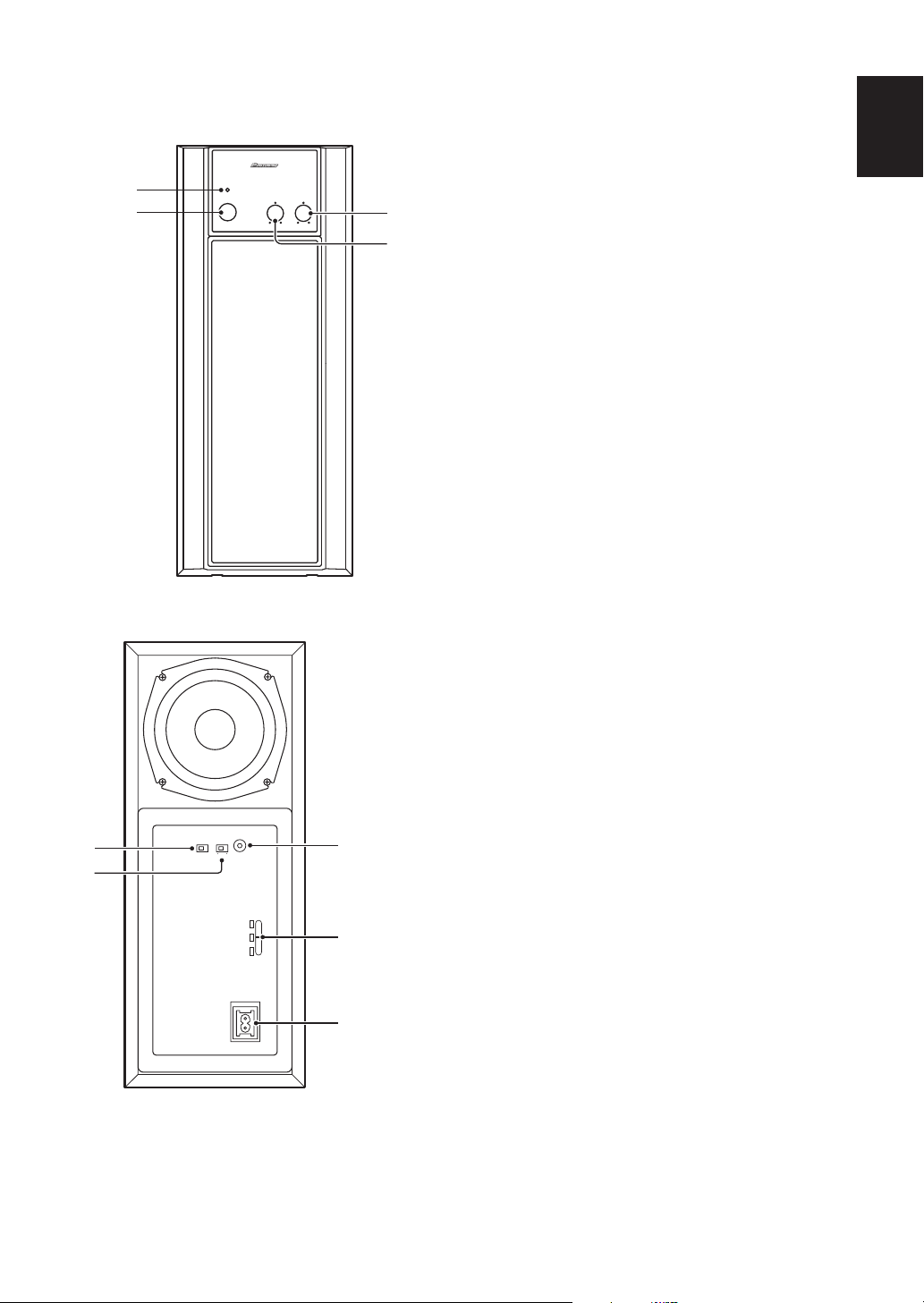
PANEL FACILITIES
FRONT PANEL
STANDBY
STANDBY/ON
POWER
LINE LEVEL
INPUT
AUTO
PHASE
0 180OFF ON
240V
220230V
110127V
AC IN
VOLUMECROSSOVER
1
2
REAR PANEL
6
7
3
4
5
LINE VOLTAGE
SELECTOR
SWITCH
8
1 Power indicator (STANDBY/ON)
Lights red when the power has been switched ON.
Lights green when the speakers receive an audio
signal. If the power is switched OFF only briefly, the
indicator lights green when power is restored. If no
signal is present for more than 8 minutes, the
subwoofer automatically reverts to standby mode and
the power indicator lights red. If, subsequently, a signal
is received, power automatically comes back on and
the power indicator lights green.
2 POWER switch
Pressing once switches the unit ON. Press again to
switch OFF.
NOTE:
If you are planning on switching the unit OFF for a long
period of time, make sure to check that the indicator light
has gone out after switching OFF.
3 Volume knob (LEVEL)
Sets the subwoofer volume.
• Turn the knob slowly from the MIN position.
• With this unit, the bass level can be independently set,
so do not turn up the bass on the stereo amplifier.
4 Crossover knob (CROSSOVER)
Sets the high limit of the frequency played back by the
subwoofer. Set to MAX when using the supplied
speaker system.
Setting Criteria
MIN.................. when the diameter of the left/right
speakers is 20 cm or more.
CENTER........... when the diameter of the left/right
speakers is 10-25 cm.
MAX................. when the diameter of the left/right
speakers is 12 cm or less.
5 Line Level Input terminal
(LINE LEVEL INPUT)
Connects to the stereo amplifier’s SUBWOOFER PREOUT terminal, with the specially provided RCA plug
cord.
6 Auto Standby switch
(AUTO STANDBY)
Switches the Auto Standby feature on/off.
Auto Standby
When switched ON (the default setting is OFF), the
Auto Standby feature becomes active. In this mode, if
there is no input signal for eight minutes the system
automatically switches to standby. The power is
automatically switched on again if an input signal is
detected.
NOTE
• There may be cases where a connected component
outputs noise or some other non-audio signal which
causes this system to automatically power on when in
Auto Standby mode. If this happens, switch off the Auto
Standby mode and switch the system on/off manually.
7
En
Page 8
7 Phase switch (PHASE 0°°°°/180°°°°)
A
C
IN
When depressed (180°), the output phase becomes
the reverse of the input signal, and when raised (0°), it
is in the same phase as the input signal.
• Normally, the switch is set to ( 0°).
But when the sound connection between the subwoofer
and the left and right speakers sounds unnatural, tyr
switching to 180° and set the switch in the position
where the sound is natural.
8 AC INLET
• Connect the power cord to the powered subwoofer
unit’s AC INLET.
• Connect the power cord to a AC socket.
TROUBLESHOOTING
OPERATION
For details regarding operating part functions, refer to page
7.
1 Turn the POWER switch (2222) ON.
• If the unit cannot be connected to the stereo amplifier or
receiver, turn the power to the stereo amplifier or
receiver ON before turning the power to the unit ON.
When turning the power OFF, turn the power to the unit
OFF before turning the power to the stereo amplifier or
receiver OFF.
2 Operate the stereo amplifier or receiver
and adjust the volume of the left/right
speakers.
3 Adjust the strength of the bass with the
Volume knob (3333).
When necessary, operate the Crossover knob (4) and
PHASE switch (7), and then adjust with the Volume
Knob (3).
Incorrect operations are often mistaken for trouble and malfunctions. If you think that there is something wrong with this
component, check the points below. Sometimes the trouble may lie in another component. Investigate the other
components and electrical appliances being used If the trouble cannot be rectified even after exercising the checks listed
below, ask your nearest PIONEER authorized service center or your dealer to carry out repair work.
SYMPTOM CAUSE REMEDY
1 No power is being supplied.
(Indicator does not light up when
power switch is turned on.)
2 No sound. (Indicator is lit.) • Connection of accessory RCA plug
3 Sound is distorted. • Level is too high. • Turn the LEVEL knob counter-
4 Howling noise occurs. • Subwoofer level is set too high. • Place the subwoofer a good distance
5 Much noise when listening to AM or
FM broadcasts.
6 System doesn’t switch to standby. • Auto Standby is switched off. • Switch on Auto Standby.
• Power supply plug is not correctly
inserted.
cord is wrong or disconnected.
• LEVEL knob is set to MIN.
• The AM loop antenna or the FM
indoor antenna is close to this unit.
• Insert plug securely.
• Check again and connect correctly.
• Turn clockwise slowly.
clockwise to lower the level.
from speakers. Turn the LEVEL knob
counter-clockwise to lower the
volume.
• Increase the distance between the
AM or FM antenna (for indoor use)
and this unit.
8
En
Page 9

English
SPECIFICATIONS
Subwoofer:
Power Requirements.............. AC110-127V/220-230V/240V~
Power Consumption....................................................... 100W
Outline Dimensions.................165(W) x 405(H) x 325(D) mm
Weight(without package) ...............................................9.4 kg
Power Amplifier:
Continous Power Output (RMS)..................................... 100W
Total Harmonic Distortion
..................................................0.5 % (40 – 200 Hz, 6 Ω, 25 W)
Power consumption (an energy-saving standby mode)
................................................................................... 0.5W less
• Above specifications are for when power supply is 230V.
Input (sensitivity at 100 Hz/impedance)
LINE LEVEL (RCA jack)...................................... 160 mV/50 kΩ
CROSSOVER Frequency ........................................... 50-200Hz
Speaker:
Enclosure .............................. Bass-reflex, floor-standing type
System............................................................13 cm cone type
(swichable), 50/60 Hz
(100Hz, T.H.D 10%, 6Ω)
(continuously variable)
Accessory Parts:
RCA plug cord x 1
Non-slip pads (1x4)
Operating instructions x 1
NOTE:
Specifications and design subject to possible modification without
notice, due to improvements.
9
En
Page 10

Posición: en la parte de debajo de la unidad.
IMPORTANTE
El triángulo equilátero con el símbolo
de un relámpago en su interior tiene
por objeto alertar al usuario de la
presencia de “voltaje peligroso” sin
aislar en el interior del producto, el cual
podría alcanzar la suficiente magnitud
como para constituir un riesgo de
descarga eléctrica para las personas.
PRECAUCIÓN:
PARA EVITAR EL RIESGO DE DESCARGA
ELÉCTRICA, NO RETIRAR LA TAPA (NI LA
CUBIERTA POSTERIOR). EL INTERIOR NO
CONTIENE PIEZAS UTILIZABLES POR EL
USUARIO. TODA REPARACIÓN DEBERÁ SER
EFECTUADA POR PERSONAL TÉCNICO
CUALIFICADO.
CAUTION
RISK OF ELECTRIC SHOCK
DO NOT OPEN
El triángulo equilátero con un signo
de admiración en su interior tiene
por objeto alertar al usuario de la
existencia de importantes
instrucciones de funcionamiento y
mantenimiento (asistencia) en el
manual que acompaña al aparato.
H002B_Sp
ADVERTENCIA: EL APARATO NO ES
IMPERMEABLE. NO PONER ALGUNA FUENTE DE AGUA
CERCA DEL APARATO, COMO VASO DE FLORES,
RECIPIENTES COSMÉTICOS Y MEDICINALES, ETC.
H001A_Sp
ATENCIÓN:EL INTERRUPTOR DE EN POWER
ESPERA ESTÁ CONECTADO EN SECUNDARIO Y
POR LO TANTO NO DESCONECTA AL APARATO DE
LA RED CUANDO ESTE EN LA POSICION DE ESPERA
(STANDBY). POR ESO INSTALE EL APARATO EN
LUGARES APROPIADOS FÁCIL DE DESCONECTAR
EL ENCHUFE DE RED EN CASO DE ACCIDENTE. EL
ENCHUFE DE RED DEL APARATO DEBERIA SER
DESCONECTADO DE LA TOMA CUANDO NON VEN
USADO POR UN LARGO PERÍODO DE TIEMPO.
H017B_Sp
VENTILACION: Cuando se instala esta unidad,
asegúrese de dejar espacio alrededor de la unidad para
proporcionar ventilación y mejorar así la radiación del calor
(por lo menos 25 cm en la parte superior, 10 cm en la parte
trasera y 10 cm de cada lado).
ADVERTENCIA: Las rendijas en el aparato es
necesario para la ventilacíon para permitir el
funcionamento del producto y para proteger este de
sobrecalentamiento, para evitar incendio. Las rendijas
no deberían ser nunca cubiertas con objectos, como
periódicos, manteles, tiendas, etc. Tambiém no poner el
aparato sobre alfombra espesa, cama, sofá o construción
de pila espesa. H040_Sp
Condiciones de Funcionamiento H045 Sp
Temperatura y humedad ambiental durante el
funcionamiento:
+5°C – +35°C (+41°F – +95°F); menos de 85 %RH (aperturas
de aireación no obstruidas)
No instalar en los siguientes lugares:
÷ lugar expuesto a la luz directa del sol o a fuerte luz
artificial
÷ lugar expuesto a alta humedad, o lugar poco aireado
Page 11

SELECTOR DE TENSIÓN DE LÍNEA
El selector de tensión está situado en el panel posterior.
Compruebe que esté correctamente ajustado antes de enchufar
el cable de alimentación a la toma de alimentación. Si la tensión
no está correctamente ajustada, ajuste el selector del modo
siguiente:
¶ Asegúrese de haber desenchufado el cable de alimentación
de la toma de alimentación antes de realizar este ajuste.
¶ Utilice un destornillador de tamaño medio (cabeza plana).
Inserte la punta del destornillador en la ranura del selector
y gírelo de modo que la marca de la tensión de su zona
señale a la flecha.
240V
220-
V
230
110-
V
127
PRECAUCIÓN 220 – 230 V
La tensión de alimentación se ha ajustado en fábrica a
220 - 230 voltios. Si la tensión de su localidad es distinta,
cambie los ajustes de los selectores de tensión.
H038 Sp
CONTENIDO
CARACTERÍ STIVAS ................ 12
ACCESORIOS INCLUIDOS...... 12
ANTES DE USAR..................... 12
MANTENIMIENTO DEL
GABINETE ................................. 12
INSTALACIÓN .......................... 13
Insalación de Altavoz ............... 13
Precauciones de instalación..... 13
EN COMBINACIÓN CON LOS
ALTAVOCES
ELEMENTOS DEL PANEL ....... 15
OPERACIÓN ............................. 16
SOLUCIÓN DE PROBLEMAS... 17
ESPECIFICACIONES ................ 17
.............................. 14
Español
Cuidados al manejar el cable de
alimentación
Tome el cable de alimentación por la clavija. No extraiga la
clavija tirando del cable, y no toque nunca el cable de la
alimentación con las manos mojadas porque podría causar
un cortocircuito o recibir una descarga eléctrica. No coloque
la unidad, un mueble u otro objeto encima del cable de
alimentación, y no lo pellizque tampoco de ninguna otra
forma. No haga nunca un nudo en el cable ni lo ate junto con
otros cables. Los cable de alimentación deberán colocarse
de forma que no los pise nadie. Un cable de alimentación
puede causar un incendio o una descarga eléctrica.
Compruebe el cable de alimentación de vez en cuando. Si
encuentra que el cable de alimentación está dañado, solicite
el reemplazo del mismo al centro de servicio autorizado
Pioneer más cercano, o a su distribuidor.
Page 12

CARACTERÍSTICAS
ANTES DE USAR
• 100 W de potencia que sirven para la reproducción de
software de video tales como sonido Dolby* Digital con
una gama dinámica amplia.
• Una entrada que se conecta al terminal SUBWOOFER
PRE-OUT
Fabricado bajo licencia de Dolby Laboratories. “Dolby” y el
símbolo con una doble D son marcas registradas de Dolby
Laboratories. Trabajos confidenciales no publicados. © 19921997 por Dolby Laboratories. Todos los derechos quedan
reservados.
ACCESORIOS INCLUIDOS
Cable de clavija RCA x 1
Almohadillas antideslizantes (1x4)
(Adhiera una almohadilla antirresbalamiento en cada
esquina de la parte inferior del altavoz de subgraves.)
Cable de alimentación
Gracias por haber adquirido este producto Pioneer.
Antes de usar el sistema de altavoces, lea estas
instrucciones para conocer la forma de obtener sus
mejores prestaciones. Guarde luego las instrucciones en
un lugar seguro y de fácil acceso para ser leídas otra vez
en caso necesario.
La impedancia nominal de este sistema de altavoces es
de 6 Ω. Conectar el sistema de altavoces a un
amplificador que tenga un régimen de impedancia de
carga de 4 a 16 ohmios (4-16 Ω marcado en las
conexiones de salida de los altavoces).
Para prevenir daños en el sistema de altavoces a causa
de sobrecarga se deberán tomar las siguientes
precauciones:
• No alimentar el sistema de altavoces excediendo la
entrada máxima permitible.
• Al conectar o desconectar las clavijas de contacto de
entrada de los amplificadores, cerciórese que estos
están apagados.
• Si se utiliza un ecualizador gráfico para aumentar el
sonido sobre una línea de alta frecuencia, no colocar el
volúmen del amplificador demasiado alto.
• No trate de forzar un amplificador de baja potencia
para que genere un volumen de sonido alto
(aumentará la distorsión armónica del amplificador y
puede dañarse el altavoz).
No tocar las superficies de vibración de los altavoces.
Estos pueden dañarse.
Estos altavoces satélite y el altavoz de subgraves est
blindados magnéticamente. Sin embargo, de acuerdo
al lugar de su instalación, puede producir
distorsión de colores si se lo ubica demasiado cerca
de la pantalla de un televisor. Si esto sucede, apague
el televisor y enciéndalo nuevamente después de 15
a 30 minutos. Si el problema persiste, coloque el
sistema de altavoces más separado del televisor.
12
Sp
MANTENIMIENTO DEL GABINETE
Para quitar el polvo o la suciedad, utilice un paño de
lustrar o un paño seco.
Si el gabinete está muy sucio utilice un paño suave
embebido en un agente de limpieza neutro diluído 5 a 6
veces con agua. Seque luego con un paño seco. No
utilice productos químicos de limpieza o cera para
muebles.
No utilice diluyentes, bencina, insecticidas u otros
productos químicos sobre o cerca de los gabinetes ya
que estos productos pueden corroer las superficies de
los gabinetes.
Page 13

INSTALACIÓN
AB
4
1
2
2
1
3
Español
7
5
3
6
4
Insalación de Altavoz
El altavoz de graves secundario reproduce los sonidos
agudos en monofónico, haciendo uso del hecho de que el
oído humano pierde el sentido de la dirección de los
sonidos de baja altura tonal. Como el sentido de dirección
se pierde, el altavoz de graves secundario puede ser
instalado casi en cualquier parte. Si se instala demasiado
alejado, no obstante, el sonido desde los altavoces
izquierdo y derecho pueden perder naturalidad.
Instalación de altavoz de graves secundario Criterio (Å)
1 Altavoz izquierdo
2 Altavoz derecho
3 Gama de instalación recomendada para los altavoces
de graves secundarios
4 Posición de audición
Un ejemplo de ubicación de los altavoces (ı)
1 Altavoz izquierdo delantero
2 Altavoz central
3 Altavoz derecho delantero
4 Altavoz de graves secundario
5 Area de audición
6 Altavoz Surround izquierdo
7 Altavoz Surround derecho
NOTA:
• Coloque los altavoces de los canales derecho e izquierdo a
distancias iguales del televisor.
• Instale la pantalla acústica central encima o debajo del TV, de
forma que el sonido del canal central quede localizado a la altura
del televisor.
• Los altavoces traseros (envolvente) son los más efectivos
cuando se instala en ubicaciones paralelas directamente al lado,
o ligeramente detrás del oyente, en un nivel de
aproximadamente 1 metro por encima de los oídos del oyente.
ATENCIÓN:
Al instalar la pantalla acústica sobre el TV, procure asegurarla
con algún medio que evite su posible caída.
De lo contrario, podría caer debido a sacudidas externas
como temblores de tierra, provocando daños en las personas
próximas o en la propia pantalla acústica.
Precauciones de instalación
• Instale la unidad en un lugar bien ventilado en donde no
quede expuesta a altas temperaturas ni alta humedad.
• No coloque la unidad cerca de estufas u otros equipos de
calefacción o en lugares expuestos a la luz directa del
sol, ya que puede tener un efecto adverso sobre el
gabinete y componentes internos. También, no instale
la unidad en donde haya mucho polvo o alta humedad, ya
que pueden ocasionarse fallas de funcionamiento o
averías. (Evite las mesas de cocina y otros lugares en
donde la unidad quede expuesta al calor, vapor y
humedad.)
• No coloque objetos pesados tales como un televisor o
un monitor de TV sobre la parte superior de la unidad.
• Mantenga la unidad alejada de dispositivos tales como
platinas de cassettes que son sensibles a los campos
magnéticos.
• Instale esta unidad alejado desde el cable de la antena
del sintonizador, ya que pueden ocasionarse ruidos con
la instalación cercana al cable de antena. En tal caso,
utilice esta unidad en una posición alejada de la antena y
del cable de antena, o cuando la reproducción de sonidos
graves extras no son requeridos, desactive la
alimentación de esta unidad.
13
Sp
Page 14

MANTENIMIENTO DE LAS
SUPERFICIES EXTERNAS
Para quitar la suciedad y tierra utilice un paño de limpieza o
•
paño seco.
Cuando la superficie está muy sucia, limpie con un paño
•
embebido en algún agente limpiador neutro diluido cinco o
seis veces en agua, exprima bien, y luego vuelva a limpiar
con un paño seco. No utilice ceras o agentes limpiadores
para muebles.
No utilice diluyentes, bencinas, rociadores de insecticidas
•
ni otros agentes químicos sobre o cerca de esta unidad, ya
que puede corroer las superficies.
CONEXIÓN DEL NIVEL DE LÍNEA
Esta conexión es para un amplificador estéreo o receptor
equipado con un terminal SUBWOOFER PRE-OUT.
Conecte al terminal LINE LEVEL INPUT de esta unidad,
usando el cable de clavija RCA provisto especialmente.
Amplificador estéreo o receptor
SUB WOOFER
PREOUT
EN COMBINACIÓN CON
LOS ALTAVOCES
Las características de frecuencias del S-HS01 combinado
con los altavoces satélite se muestra a continuación. Como
se muestra en estas figuras, la gama de bajas frecuencias
ha sido mejorada.
• Estas características especiales se obtienen en una
cámara en la que no hay eco. El efecto de un altavoz de
subgraves adicional en una sala de escucha
convencional es mejor que el que la gráfica indica
cuando el altavoz se coloca adecuadamente.
Altavoces satélite + Altavoz de subgraves
Altavoz satélite
ESPUESTA (dB)
FRECUENCIA (Hz)
• Con la reproducción de Dolby* Digital, se recomienda
el establecimiento de un canal especial, y con la
reproducción de LFE (efecto de frecuencia bajo: efecto
de sonido similar al tremor de la tierra, cuyo efecto es
intensificar la fuerza del video), el S-HS02 es
especialmente efectivo.
Cable de clavija RCA suministrado
Altavoz de graves secundario (Panel trasero)
LINE LEVEL
LINE LEVEL
INPUT
AUTO
STANDBY
PHASE
OFF ON
0 180
240V
220-
230V
110-
127V
AC IN
INPUT
NOTA:
Cuando se conecta al terminal PRE-OUT para el canal
central Surround del amplificador o receptor estéreo, los
graves sólo se oyen por el canal central, por lo que serán
insuficientes,
Dolby* Digital
Dolby Digital es el nombre del sistema digital multicanal de
sonido envolvente Dolby que fue desarrollado por Dolby
Surround, como una continuación de Dolby Pro Logic
Surround.
Dolby Digital también es referido como un sistema de 5.1
canales. Esto se debe a que tiene 5 canales en la gama de
frecuencia de 20Hz – 20kHz (delantera izquierda y derecha,
centro y trasera izquierda y derecha) y un canal
independiente para el altavoz de sonidos graves
secundario. El canal del altavoz de sonidos graves
secundario también es referido como LFE (Efecto de
frecuencia baja).
El canal LFE se usa de acuerdo a los gustos individuales
para aumentar el efecto de los sonidos graves.
14
Sp
Page 15

ELEMENTOS DEL PANEL
O
PANEL DELANTERO
1
2
6
7
STANDBY/ON
POWER
PANEL TRASERO
LINE LEVEL
INPUT
AUTO
PHASE
STANDBY
0 180OFF ON
240V
220230V
110127V
AC IN
VOLUMECROSSOVER
5
SELECT
TENSIÓN
LÍNEA
8
1 Indicador de la alimentación(STANDBY/ON)
Se enciende en color rojo cuando la alimentación se
encuentra conectada. Se enciende en color verde
cuando los altavoces reciben una señal de audio. Si la
alimentación se desconecta sólo brevemente, el
indicador se encenderá en color verde cuando vuelva a
conectarse la alimentación. Si no entra ninguna señal
durante 8 minutos, el altavoz de subgraves se pondrá
3
4
automáticamente en el modo de espera y el indicador
de la alimentación se encenderá en color rojo. Si se
recibe posteriormente una señal, la alimentación se
conectará automáticamente y el indicador de
Español
alimentación se encenderá en color verde.
2 Conmutador POWER
Al pulsarlo una vez se enciende la unidad. Al pulsarlo
otra vez, la unidad se apaga.
NOTA:
Si está planeando apagar la unidad durante un largo periodo
de tiempo, asegúrese de comprobar que el indicador se
apague después de desconectar la alimentación.
3 Control del volumen (LEVEL)
Ajusta el volumen del altavoz de subgraves.
• Gire lentamente el control desde la posición MIN.
• Con este aparato, el nivel de los graves puede
ajustarse independientemente, por lo que no es
necesario incrementar los graves en el amplificador
estéreo.
4 Control de cruce (CROSSOVER)
Ajusta el límite alto de las frecuencias reproducidas con
el altavoz de subgraves. Ajústelo en MAX cuando
emplee el sistema de altavoces suministrado.
Criterio para el ajuste
MIN........... Cuando el diámetro de los altavoces
izquierdo/derecho es de 20 o más cm.
CENTER ....Cuando el diámetro de los altavoces
izquierdo/derecho es de 10-25 cm.
MAX.......... Cuando el diámetro de los altavoces
izquierdo/derecho es de 12 o menos cm.
5 Terminal de entrada de nivel de línea
(LINE LEVEL INPUT)
Se conecta al terminal SUBWOOFER PRE-OUT del
amplificador estéreo mediante el cable con clavijas
RCA especialmente suministrado.
6 Interruptor de espera automática
(AUTO STANDBY)
Activa y desactiva la función de espera automática.
Espera automática
Cuando se activa (ON) (el ajuste predeterminado es
OFF de desactivado), la función de espera automática
se activa. En este modo, si no hay señal de entrada
durante ocho minutos, el sistema se establece
automáticamente en el modo de espera. La
alimentación se vuelve a conectar automá.
NOTA:
• Puede haber casos en los que un componente
conectado emite ruido o alguna otra señal que no es de
audio, lo cual causa que la alimentación de este sistema
se conecte automáticamente cuando está en el modo de
espera automática. Si así sucede, desactive el modo de
espera automática y conecte y desconecte
manualmente la alimentación del sistema.
15
Sp
Page 16

7 Interruptor de fase (PHASE 0˚/180˚)
A
C
IN
Cuando está presionado (180˚), la fase de salida para a
ser la inversa de la señal de entrada, y cuando está
subido (0˚), está en la misma fase que la señal de
entrada.
• Normalmente, el interruptor se ajusta en (0˚).
Pero cuando la conexión del sonido entre el altavoz de
subgraves y los altavoces izquierdo y derecho suena sin
naturalidad, pruebe cambiando a 180˚ y ajuste en
interruptor en la posición que proporcione un sonido
natural.
8 Entrada de CA (AC INLET)
• Conecte el cable de alimentación a la toma AC INLET de
la unidad de altavoz de subgraves alimentada.
• Enchufe el cable de alimentación a una toma de
corriente.
OPERACIÓN
Para los detalles respecto a la operación de las funciones de
las partes, refiérase a la página 15.
1 Active la alimentación con el interruptor
POWER (2222).
• Si la unidad no puede ser conectada al amplificador
estéreo o receptor, active la alimentación del
amplificador estéreo o receptor antes activar la
alimentación de la unidad. Cuando se desactiva la
alimentación de la unidad, desactive la alimentación de la
unidad antes de desactivar la alimentación del
amplificador estéreo o receptor.
2 Opere el amplificador estéreo o receptor
y ajuste el volumen de los altavoces
izquierdo y derecho.
3 Ajuste la intensidad de los graves con el
control de volumen (3333).
Cuando sea necesario, opere el control de cruce (4) y
el interruptor PHASE (7), y luego realice el ajuste con
el control de volumen (3).
16
Sp
Page 17

SOLUCIÓN DE PROBLEMAS
Las operaciones incorrectas son a menudo confundidas por averías o fallas en el funcionamiento. Si piensa que algo está
fallando con este componente, compruebe los puntos siguientes. Algunas veces el problema puede estar en otro
componente. Revise los otros componentes y aparatos eléctricos que se están usando, si el problema no puede resolverse
aun luego de realizar las comprobaciones listadas a continuación, solicite a su concesionario o centro de servicio autorizado
PIONEER para que lleve a cabo el trabajo de reparación.
Síntoma Causa Solución
1 No hay suministro de alimentación
(el indicador no se ilumina cuando se
activa el interruptor de alimentación.)
2 No hay sonido (indicador iluminado) • La conexión del cable con clavijas
3 Sonido distorsionado. • El nivel está muy alto. • Gire la perilla LEVEL hacia la
4 Se produce sonidos de alta
frecuencia.
5 Demasiado ruido cuando se escucha
emisiones de AM o FM.
6 El sistema no se establece en el
modo de espera.
• El enchufe de suministro de energía
no está correctamente insertado.
RCA suministrado está mal hecha o
el cable no está conectado.
• La perilla LEVEL está fijada en MIN.
• El nivel de altavoz secundario está
ajustado demasiado alto.
• La antena de cuadro de AM o la
antena interior de FM está muy cerca
de la unidad.
• La espera automática se ha
desactivado.
• Inserte correctamente el enchufe.
• Compruebe de nuevo y conecte
correctamente.
• Gire hacia la derecha lentamente.
izquierda para disminuir el nivel.
• Coloque el altavoz de graves
secundario a una buena distancia de
los altavoces. Gire la perilla LEVEL
hacia la izquierda para disminuir el
volumen.
• Aumente la distancia entre la antena
de AM o FM (para uso interior) y esta
unidad.
• Active el modo de espera
automática.
Español
ESPECIFICACIONES
Graves secundario:
Alimentación......................... CA de 110-127/220-230/240 V~
(conmutable), 50/60 Hz
Consumo ......................................................................... 100 W
Dimensiones exteriores
..........................................165 (An) x 405 (Al) x 325 (Prof) mm
Peso (sin embalaje) ........................................................9,4 kg
Amplificador de potencia:
Potencia continua de salida (RMS) ...............................100W
(100Hz, T.H.D 10%, 6Ω)
Distorsión armónica total ................................................0.5 %
(40 – 200 Hz, 6Ω, 25 W)
Consumo de energía (en el modo de espera de ahorro de
energía)....................................................... 0,5 W o menos
• Las especificaciones anteriores corresponden a una
alimentación eléctrica de 230 V.
Entrada (sensibilidad a 100 Hz/impedancia)
LINE LEVEL (Toma RCA) ...................................160 mV/50 kΩ
Frecuencia de cruce..... 50-200 Hz (continuamente variable)
Altavoz
Caja
......Reflejo de graves, tipo de colocación vertical en el suelo
Sistema...................................................Tipo código de 13 cm
Piezas accesorias:
Cable con clavijas RCA x 1
Almohadillas antideslizantes (4 x 1)
Manual de instrucciones x 1
NOTA:
Las especificaciones y el diseño están sujetos a cambios sin previo
aviso debido a futuras mejoras.
17
Sp
Page 18

H017BChH
電源導線注意事項
插入或拔除電源線請拿著插頭部分進行。請勿拉拽軟
線來拔除插頭,當手帶濕氣時切忌觸摸電源線,否則
可能會造成短路或觸電。請勿在電源線上安放本機、
傢具,或其他物件,或以任何做法夾緊軟線。軟線切
忌打結或用其他軟線捆扎。電源線的路徑應布置成不
會形成階梯狀。損傷的電源線可能會導致失火或觸
電。請時常檢查電源線。當發現到損傷時,可請求就
近的先鋒公司認可維修中心或貴地經銷店予以更換。
25 10
10
Page 19

線路電壓選擇開關
線路電壓選擇開關位於本機的背面板上。在將電源
線插頭插入電源插座之前,請確認設定是否正確。
如果電壓沒有正確設定,或搬遷到電壓需求不同的
地方,請按如下要領調整本選擇開關 ﹕
¶ 進行本調整之前, 必須從電源插座拔除電源線。
¶ 使用中型(扁頭)螺絲刀。將螺絲刀的尖頭插入
選擇開關的槽中並轉動以使貴地電源電壓標記指
向箭頭。
H038 ChH
目錄
特性 ........................... 20
附屬配件 ....................... 20
使用之前 ....................... 20
外殼清潔方法 ................. 20
安裝 ........................... 21
揚聲器安裝 ................... 21
安裝注意事項 ................. 21
240V
220-
V
230
110-
V
127
注意220∼230V
電源電壓的工廠初期設定為220∼230 V。如果貴地電壓
不同,請改變電壓選擇開關的設定。 H038 ChH
揚聲器連接 ..................... 22
面板設施 ....................... 23
操作 ........................... 24
檢修 ........................... 25
規格 ........................... 25
19
ChH
Page 20

特性
使用之前
100 W 功 率適合於以寬闊的動態範圍播放視頻軟體,如
杜比 * 數碼軟體。
連接到 SUBWOOFER PRE-OUT 端子的輸入
“杜比”、“Dolby”和雙 D 標志是杜比實驗室的商標。
不予發行的保密作品。
權所有,翻印必究。
杜比實驗室 1992-1997 年。版
©
附屬配件
RCA 插頭線× 1
防滑墊 (1 × 4)
(將防滑墊片黏到亞低音揚聲器的底面各隅角。)
電源線
承蒙選購先鋒牌產品,謹致謝忱。
為能充分發揮本 揚聲器系統的性能,請通讀本 使用
說明書。通讀後請妥善保管,以備使用中隨時參閱。
本揚聲器系統的額定阻抗是 6
-16
16
為防止過大輸入損壞揚聲器,請遵守如下事項:
強烈沖撞共振板可造成損傷。不要用手碰觸共振板。
這些衛星揚聲器和重低音揚聲器為磁屏蔽類型。
不過,依安裝位置不同,有時可引起電視機圖像偏色。
若出現這種情況,可關閉電視機,待15-30分鐘後再打
開。若電視機圖像仍偏色,則要將揚聲器遠離電視機。
外殼清潔方法
用拋光布或干布輕輕擦拭灰塵。
骯臟較重時,用軟布蘸取經稀釋 5 - 6 倍的中性洗劑擦
去污垢,然後用干布擦去水分。不要使用家具蠟或清
潔劑。
千萬不要使用信那水、汽油、噴霧式殺虫劑或其他化
學溶劑擦拭或噴濺,否則可腐蝕 外殼表面。
的立體聲擴大器 (揚聲器輸出端子標有 4 -
Ω
的擴大器)。
Ω
揚聲器系統的輸入量不要超過容許輸入值。
•
連接或拔下擴大器的銷針式插頭時,要關閉擴大
•
器電源。
用圖示均衡器大幅度增強高音時,不要過於提高
•
音量。
不要試圖強製讓低功率的放大器發出高音 (放大
•
器的諧波失真將會增加,並且會損壞揚聲器)
。請連接負荷阻抗為 4
Ω
20
ChH
Page 21

安裝
AB
4
1
2
2
3
1
7
5
3
6
4
注意:
揚聲器安裝
次低音揚聲器是利用人們的耳朵在低音域中會失去方向
感覺這一特點,從而可用單聲道來播放重低音。由於沒
有方向感覺,安放位置相當地隨便,但是如果安放在過
於遠的位置,則有時會出現左右揚聲器所發出的聲音互
相之間不自然與不協調的現象。
在與電視機相等的距離安置左和右揚聲器。
•
請將中央揚聲器安裝於電視機的上方或下方,如此可
•
使中央聲道的聲音位於電視螢幕的位置。
后(環繞 ) 揚聲器直接對向側面平行或稍向聽眾后面
•
安裝時,安裝位置處於聽眾耳朵上方 1 米處最為有
效。
次低音揚聲器設備標準 (Å)
左揚聲器
1
右揚聲器
2
次低音揚聲器建議安裝範圍
3
4
收聽位置
揚聲器位置示例 (ı)
前左揚聲器
1
中心揚聲器
2
3
前右揚聲器
次低音揚聲器
4
收聽範圍
5
環繞聲揚聲器 (左)
6
環繞聲揚聲器 (右)
7
注意:
當您將中央揚聲器安裝於電視機上方時,請使用膠帶
或其他適當的物品固定揚聲器。
否則,當發生外在因素的震盪時 (例如地震),揚聲器
可能會從電視機上摔落。如此將會造或附近物品的危
險或揚聲器本身的損壞。
安裝注意事項
將裝置安裝在通風良好的位置,不要暴露在高溫或高
•
濕度的地方。
不要將裝置放在靠近火爐、其它發熱設備或暴露在陽
•
光直射的位置,因為這樣會對箱體和內部元件產生不
良影響。另外,不要將裝置安裝在太臟或太潮濕的地
方,這樣會引起設備故障或損壞。 ( 避免將裝置安放
在爐台上和使裝置暴露在高溫、蒸氣和煤鑷的地方。)
不要將電視機或電視監視器等重物品放在裝置上。
•
將裝置遠離於對磁場敏感的盒式錄音機。
•
21
ChH
Page 22

請把調諧器的天線電纜放置於遠離電視機的地方,放
衛星揚聲器+重低音揚聲器
響應(
)
•
太靠近會產生雜音。當產生雜音時,把天線或天線電
纜遠離電視機後再使用。在容許限度內重低音的再現
不可能時,請將電視機的電源關閉。
線性電平接線
在立體聲放大器或者是接收機中附帶有低音揚聲器前置
輸出用端子時進行連接。
插頭線於本機的 LINE LEVEL INPUT 端子進行連接。
外部接口的維護
•
使用一塊拋光布或乾布擦去灰塵。
•
當表面很髒時,用一塊軟布沾上用 5 或 6 倍水稀
釋的中性清潔劑擦去灰塵,然后再用乾布擦。不要
使用家俱蠟。
•
千萬不要在裝置上或者裝置附近使用稀釋劑、苯、
殺虫噴霧劑其它化學藥品。因為這些物品會腐蝕裝
置表面。
揚聲器連接
S-HS02 與衛星揚聲器結合的頻率特性如下所示。如下圖
所示,低頻範圍被改善。
這些特性數值為無回聲室中的測試數據。在普通收聽
•
環境中,如果添加重低音揚聲器,且放置得當,其效
果將比圖中顯示的更好。
dB
衛星揚聲器
立體聲放大器或接收機
次低音揚聲器(后面板)
LINE LEVEL
INPUT
AUTO
PHASE
STANDBY
OFF ON
0 180
240V
220230V
110127V
AC IN
SUB WOOFER
PREOUT
提供的 RCA 插頭線
LINE LEVEL
INPUT
注意:
當連接到立體聲放大器或接收機上用於環繞聲中央聲道
的PRE-OUT 端子時,低音只能在中央聲道上聽到,因此
低音將會不足夠。
•
關於杜比 * 數碼
杜比數碼,繼承和發展了從杜比環繞到杜比前邏輯環繞
的特點,是杜比環繞多頻道、數碼系統的名稱。
杜比數碼 同時也被稱之為 5.1 頻道系統。因為它具有
從20Hz∼20 kHz 的頻率數的 5 個頻道 ( 前左、前
右、中心、后左、后右 ) 和具有獨立的環繞用頻道。環
繞聲頻道也被稱之為 LFE ( 低頻效果,Low Frequency
Effect)。
LFE 頻道,可作為更加合乎於希望比低音域強烈時而使
用的頻道。
22
ChH
頻率(Hz)
關於杜比 * 數碼的播放,建議您將其設定為次低音揚
聲器的專用播放頻道。尤其是對於 LFE ( 低頻效果=
為了增加電影等的感染力而產生的如同地鳴般效果的
聲音 ) 的播放,S-HS02 是很有效的。
Page 23

STANDBY/ON
1
2
前面板
6
7
后面板
POWER
面板設施
電源指示燈 (STANDBY/ON)
1
當電源開關處於 ON 時﹐燈為紅色。當揚聲器接收音頻
信號時﹐燈為綠色。如果電源僅被暫時切斷﹐恢復時指
示燈為綠色。如果無信號表示超過 8 分鐘﹐重低音揚聲
器自動回復到待機模式﹐電源指示燈變為紅色。如果隨
後接收到信號﹐電源自動恢復﹐電源指示燈變為綠色。
2
VOLUMECROSSOVER
3
電源開關 (POWER)
按下一次開關機器打開。再按下一次則關閉。
4
注意﹕
如果您打算長時間關閉本機﹐在切斷電源後請務必確認
指示燈已被關閉。
3
音量旋鈕 (LEVEL)
設定亞低音揚聲器的音量。
•
從MIN 位置慢慢旋轉旋鈕。
•
利用本機時,能夠單獨設定低音電平,因此請勿
在立體聲放大器上增大低音。
4
交叉旋鈕 (CROSSOVER)
設定由亞低音揚聲器放出的頻率的上限。使用配備
的揚聲器系統時,設定成 MAX。
設定範圍
MIN ........左∕右揚聲器的直徑為 20cm 或以上。
CENTER ........ 左∕右揚聲器的直徑為 10-25cm。
MAX ........左∕右揚聲器的直徑為 12cm 或以下。
5
線路電平輸入端子 (LINE LEVEL INPUT)
用特別供應的 RCA 插頭軟線聯接到立體聲放大器的
SUBWOOFER PREOUT 端子。
自動待機開關 (AUTO STANDBY)
6
通∕斷自動待機功能。
自動待機
轉換成
功能起作用。在本模式,如果
8分鐘沒有輸入信號,本機自動轉換成待機。如果
檢測到輸入信號,電源被自動接通。
(工廠初期設定為
ON
)時,自動待機
OFF
LINE LEVEL
INPUT
STANDBY
AUTO
PHASE
0 180OFF ON
5
注意
在自動待機模式,可能會有導致所聯接組件的輸出會
•
造成本機自動接通電源的噪音或一些其他非音頻信號
的情況。遇此情況時,關掉自動待機模式並手動打開
∕關閉電源。
相位開關 (PHASE 0°∕ 180°)
240V
220230V
110127V
線路電壓選擇開關
AC IN
8
7
按住 (180°)時,輸出相位成為與輸入信號相反,
而昇起 (0°)時,成為與輸入信號相同的相位。
通常,本開關設定成 (0°)。
•
但是,當亞低音揚聲器與左右揚聲器之間的聲音
不自然時,請試圖轉換成 180°並將本開關置於聲
音自然的地方。
23
ChH
Page 24

交流輸入端子
AC IN
8
將電源線聯接到打開了電源的亞低音揚聲器的交
•
流輸入端子。
將電源線連接到牆壁輸出插座。
•
操作
關於操作部分功能的詳細情況請您查看第 23 頁。
1
開啟電源開關 (2) (POWER)
•
如果立體聲放大器及耳機不能連動時,請您先開
啟立體聲放大器或者耳機的電源之后,再開啟本
機。當關閉電源時,請您先關閉本機之后,再關
閉立體聲放大器或者耳機。
2
操作立體聲放大器及耳機,使其發出聲音,調整左
右左右揚聲器的音量。
用音量旋鈕 (3) 調節低音的強度。
3
需要時,操作交叉旋鈕 (4)和相位開關 (7),
然后用音量旋鈕 (3)進行調節。
24
ChH
Page 25

檢修
如果不進行正確的操作通常會產生故障。如果您認為本組合裝置有問題,可按如下所述進行檢查。有時故障可能發
生在其它的元件上。如果按下表檢查之后故障仍然不能排除,請檢查其它元件和電氣裝置,向就近的 PIONEER 授
權服務中心或代理商請求進行修理。
現 象 原 因 修 理
1
無電源
( 電源開關打開時指示燈不亮 )。
2
無聲 ( 指示燈量 )。
3
聲音畸變。
產生顫噪效應噪音。
4
聽調諧設備時產生很多雜音。
5
6
本機無法轉換成待機模式。
•
電源插頭沒有正確插入。
•
附屬的 RCA 插頭纜線連接錯誤或沒有
連接。
•
LEVEL 旋鈕設置為 MIN。
•
電平太高。
次低音揚聲器電平太高。
•
AM 的環狀天線或 FM 的室內天線靠電
•
視機太近。
•
自動待機模式被關掉。
•
正確插入插頭。
•
重新檢查和正確接線。
•
慢慢地順時針旋轉。
•
逆時針旋轉 LEVEL 旋鈕到低電平。
將次低音揚聲器離開揚聲器一定距
•
離。逆時針旋轉 LEVEL 旋鈕至低電
平。
將AM或FM 的室內天線遠離電視
•
機。
•
打開自動待機模式。
規格
次低音:
功率 . . . 110 - 127/220 - 230/240
功率消耗 .............. .... 100瓦
外部尺寸 .....165(長)×405(高)×325( 深 )mm
重量(無包裝 ) ........... .... 9.4kg
功率放大器﹕
連續功率輸出 (RMS)
.. ........100瓦(100Hz, T.H.D 10%, 6 Ω )
總諧波失真 ......0.5%(40∼200Hz﹐6 Ω﹐25 瓦 )
功率消耗 (節能待機模式) . . . . . . . 0.5W 以下
•
上述規格為電源為 230V 時的數字。
LINE LEVEL(RCA 插座 ) ........ . 160mV/50k Ω
交叉頻率 . . . . . . . . .50 ∼ 200Hz (連續可變)
輸入 ( 在 100Hz/ 阻抗下的靈敏度 )
揚聲器﹕
內裝物 .............低音反射﹐落地類型
系統 ................ .13cm 錐形類型
V∼ AC
(可調)﹐
50/60Hz
附件:
RCA 插座纜線× 1
防滑墊 (4 × 1)
操作指南 × 1
注意:
規格和外形設計若有變更,恕不預告。
25
ChH
Page 26

26
ChH
Page 27

27
ChH
Page 28

Published by Pioneer Corporation.
Copyright © 2003 Pioneer Corporation.
All rights reserved.
PIONEER CORPORATION
4-1, Meguro 1-Chome, Meguro-ku, Tokyo 153-8654, Japan
PIONEER ELECTRONICS (USA) INC.
P.O. BOX 1540, Long Beach, California 90810-1540, U.S.A. TEL: (800) 421-1404
PIONEER ELECTRONICS OF CANADA, INC.
300 Allstate Parkway, Markham, Ontario L3R OP2, Canada TEL: (905) 479-4411
PIONEER EUROPE NV
Haven 1087, Keetberglaan 1, B-9120 Melsele, Belgium TEL: 03/570.05.11
PIONEER ELECTRONICS ASIACENTRE PTE. LTD.
253 Alexandra Road, #04-01, Singapore 159936 TEL: 656-472-1111
PIONEER ELECTRONICS AUSTRALIA PTY. LTD.
178-184 Boundary Road, Braeside, Victoria 3195, Australia, TEL: (03) 9586-6300
PIONEER ELECTRONICS DE MEXICO S.A. DE C.V.
Blvd.Manuel Avila Camacho 138 10 piso Col.Lomas de Chapultepec, Mexico,D.F. 11000 TEL: 55-9178-4270
K002E
Printed China SRD1252-A
 Loading...