

Pioneer S-TA505 User Manual

HTP-55
SX-SW505
S-TA505
HTP-33
SX-SW303
S-ST303
Audio Multi-channel Receiver Subwoofer
Speaker System
Audio Multi-channel Receiver Subwoofer
Speaker System
Operating Instructions
Thank you for buying this Pioneer product.
Please read through these operating instructions so that you will know how to operate your model properly. After
you have finished reading the instructions, put them in a safe place for future reference.
IMPORTANT
CAUTION
RISK OF ELECTRIC SHOCK
DO NOT OPEN
The lightning flash with arrowhead symbol,
within an equilateral triangle, is intended to
alert the user to the presence of uninsulated
"dangerous voltage" within the product's
enclosure that may be of sufficient
magnitude to constitute a risk of electric
shock to persons.
CAUTION:
TO PREVENT THE RISK OF ELECTRIC
SHOCK, DO NOT REMOVE COVER (OR
BACK). NO USER-SERVICEABLE PARTS
INSIDE. REFER SERVICING TO QUALIFIED
SERVICE PERSONNEL.
The exclamation point within an equilateral
triangle is intended to alert the user to the
presence of important operating and
maintenance (servicing) instructions in the
literature accompanying the appliance.
D3-4-2-1-1_En-A
WARNING
This equipment is not waterproof. To prevent a fire
or shock hazard, do not place any container filed
with liquid near this equipment (such as a vase or
flower pot) or expose it to dripping, splashing, rain
or moisture.
D3-4-2-1-3_A_En
Operating Environment
Operating environment temperature and humidity:
+5 ºC to +35 ºC (+41 ºF to +95 ºF); less than 85 %RH
(cooling vents not blocked)
Do not install this unit in a poorly ventilated area, or in
locations exposed to high humidity or direct sunlight (or
strong artificial light)
CAUTION
The STANDBY/ON switch on this unit will not
completely shut off all power from the AC outlet.
Since the power cord serves as the main disconnect
device for the unit, you will need to unplug it from
the AC outlet to shut down all power. Therefore,
make sure the unit has been installed so that the
power cord can be easily unplugged from the AC
outlet in case of an accident. To avoid fire hazard,
the power cord should also be unplugged from the
AC outlet when left unused for a long period of time
(for example, when on vacation).
D3-4-2-1-7c_A_En
If the AC plug of this unit does not match the AC
outlet you want to use, the plug must be removed
and appropriate one fitted. Replacement and
mounting of an AC plug on the power supply cord of
this unit should be performed only by qualified
service personnel. If connected to an AC outlet, the
cut-off plug can cause severe electrical shock. Make
sure it is properly disposed of after removal.
The equipment should be disconnected by removing
the mains plug from the wall socket when left
unused for a long period of time (for example, when
on vacation).
WARNING
To prevent a fire hazard, do not place any naked
flame sources (such as a lighted candle) on the
equipment.
WARNING
Before plugging in for the first time, read the following
section carefully.
The voltage of the available power supply differs
according to country or region. Be sure that the
power supply voltage of the area where this unit
will be used meets the required voltage (e.g., 230V
or 120V) written on the rear panel.
D3-4-2-2-1a_A_En
D3-4-2-1-7a_A_En
D3-4-2-1-4_A_En

POWER-CORD CAUTION
Handle the power cord by the plug. Do not pull out the
plug by tugging the cord and never touch the power
cord when your hands are wet as this could cause a
short circuit or electric shock. Do not place the unit, a
piece of furniture, etc., on the power cord, or pinch the
cord. Never make a knot in the cord or tie it with other
cords. The power cords should be routed such that they
are not likely to be stepped on. A damaged power cord
can cause a fire or give you an electrical shock. Check
the power cord once in a while. When you find it
damaged, ask your nearest PIONEER authorized
service center or your dealer for a replacement.
S002_En
VENTILATION CAUTION
When installing this unit, make sure to leave space
around the unit for ventilation to improve heat
radiation (at least 5 cm at top, 5 cm at rear, and 5
cm at each side).
WARNING
Slots and openings in the cabinet are provided for
ventilation to ensure reliable operation of the
product, and to protect it from overheating. To
prevent fire hazard, the openings should never be
blocked or covered with items (such as newspapers,
table-cloths, curtains) or by operating the
equipment on thick carpet or a bed.
D3-4-2-1-7b_A_En
English
This product is for general household purposes. Any
failure due to use for other than household purposes
(such as long-term use for business purposes in a
restaurant or use in a car or ship) and which
requires repair will be charged for even during the
warranty period.
K041_En
What’s in the box
Please confirm that the following items are all supplied.
Receiver subwoofer (SX-SW505/SX-SW303) box:
• Remote control (page 15)
• AA/R6 dry cell batteries (to confirm operation) x2
(page 16)
• Display unit (page 14)
• Power cord x2 (page 13)
• AM loop antenna (page 11)
• FM wire antenna (page 11)
• Display cable (page 11)
• Coaxial cable (page 27)
• Microphone (for Auto MCACC setup) (page 17)
• These operating instructions
5 cm
5 cm 5 cm
Speakers (S–TA505) box:
• Speakers (front x2, surround x2, center x1) (page 12)
• Speaker cables x5 (page 11)
• Non-skid pads (large) x4 (page 5)
• Non-skid pads (large) x16 (page 5)
• Non-skid pads (small) x4 (page 5)
• Speaker stand bases x4 (page 5)
• Screws (for bases) x12 (page 5)
Speakers (S–ST303) box:
• Speakers (front x2, surround x2, center x1) (page 12)
• Speaker cables x5 (page 11)
• Non-skid pads (large) x4 (page 7)
• Non-skid pads (small) x20 (page 7)
• Speaker stands x2 (page 8)
• Screws (for speaker stands) x2 (page 8)
3
En

Contents
Contents
What’s in the box
01 Speaker Setup Guide
Safety precautions when setting up
Home theater sound setup (HTP-55)
Home theater sound setup (HTP-33)
Standard surround setup
Front surround setup
Wall mounting the speakers
Before mounting
Wall mounting the center speaker
Wall mounting the other speakers (HTP-33)
Additional notes on speaker placement
02 Connecting up
Basic connections
Using this system for TV audio
03 Controls and displays
Display unit
Display
Remote control
Using the remote control
Putting the batteries in the remote control
04 Getting started
System demo setting
Using the Auto MCACC setup for optimal surround
. . . . . . . . . . . . . . . . . . . . . . . . . . . . . . . . . . . . .17
sound
05 Listening to your system
Auto listening mode
Listening in surround sound
Dolby Pro Logic II Music settings
Using Front Surround (HTP-33 only)
Using Advanced Surround
Listening in stereo
Using the Sound Retriever
Listening with Acoustic Calibration EQ
Enhancing dialogue
Using Quiet and Midnight listening modes
Adjusting the bass and treble
Boosting the bass level
. . . . . . . . . . . . . . . . . . . . . . . . . . . . .3
. . . . . . . . . . . . . . .5
. . . . . . . . . . . . . . .5
. . . . . . . . . . . . . . .6
. . . . . . . . . . . . . . . . . . . . . .6
. . . . . . . . . . . . . . . . . . . . . . . . .7
. . . . . . . . . . . . . . . . . . . . .8
. . . . . . . . . . . . . . . . . . . . . . . . . . . .8
. . . . . . . . . . . . . . .8
. . . . . . . .8
. . . . . . . . . . . .9
. . . . . . . . . . . . . . . . . . . . . . . . . . .10
. . . . . . . . . . . . . . . . . .13
. . . . . . . . . . . . . . . . . . . . . . . . . . . . . . . .14
. . . . . . . . . . . . . . . . . . . . . . . . . . . . . . . . . . .14
. . . . . . . . . . . . . . . . . . . . . . . . . . . . . .15
. . . . . . . . . . . . . . . . . . . . . .16
. . . . . . . . .16
. . . . . . . . . . . . . . . . . . . . . . . . .17
. . . . . . . . . . . . . . . . . . . . . . . . . .19
. . . . . . . . . . . . . . . . . . . .19
. . . . . . . . . . . . . . .20
. . . . . . . . . . . . . .20
. . . . . . . . . . . . . . . . . . . . .21
. . . . . . . . . . . . . . . . . . . . . . . . . . .21
. . . . . . . . . . . . . . . . . . . . .21
. . . . . . . . . . . .21
. . . . . . . . . . . . . . . . . . . . . . . . . .22
. . . . . . . .22
. . . . . . . . . . . . . . . . . . .22
. . . . . . . . . . . . . . . . . . . . . . . .22
06 Listening to the radio
Listening to the radio
Improving poor FM reception
Improving poor AM sound
Memorizing stations
Listening to station presets
Changing the frequency step
. . . . . . . . . . . . . . . . . . . . . . . . .23
. . . . . . . . . . . . . . . . . .23
. . . . . . . . . . . . . . . . . . . .23
. . . . . . . . . . . . . . . . . . . . . . . . .24
. . . . . . . . . . . . . . . . . . .24
. . . . . . . . . . . . . . . . . .24
07 Surround sound settings
Using the Setup menu
Channel level setting
Speaker distance setting
Dynamic Range Control
Dual mono setting
Adjusting the channel levels using the test tone
. . . . . . . . . . . . . . . . . . . . . . . .25
. . . . . . . . . . . . . . . . . . . . . . . .25
. . . . . . . . . . . . . . . . . . . . .25
. . . . . . . . . . . . . . . . . . . . . .26
. . . . . . . . . . . . . . . . . . . . . . . . . .26
08 Other connections
Connecting auxiliary components
Connecting an analog audio component
Listening to an external audio source
Connecting external antennas
Using this unit with a Pioneer plasma display
SR+ Setup for Pioneer plasma displays
Using the SR+ mode with a Pioneer plasma
. . . . . . . . . . . . . . . . . . . . . . . . . . . . . . . . . . .29
display
About the control out jack
. . . . . . . . . . . . . . .27
. . . . . . . . .27
. . . . . . . . . . . . .27
. . . . . . . . . . . . . . . . . .27
. . . . . . . . . .28
. . . . . . . . . . . . . . . . . . . . .29
09 Additional information
Setting the sleep timer
Dimming the display
DTS CD setting
Resetting the system
Installation and maintenance
Hints on installation
Glossary
. . . . . . . . . . . . . . . . . . . . . . . . . . . . . . . . . . .31
Setting up the remote to control your TV
Using the TV remote control buttons
Preset code list
Troubleshooting
General
. . . . . . . . . . . . . . . . . . . . . . . . . . . . . . . . . .33
Tuner
. . . . . . . . . . . . . . . . . . . . . . . . . . . . . . . . . . . .34
Error Messages
Specifications
. . . . . . . . . . . . . . . . . . . . . . . .30
. . . . . . . . . . . . . . . . . . . . . . . . .30
. . . . . . . . . . . . . . . . . . . . . . . . . . . . . .30
. . . . . . . . . . . . . . . . . . . . . . . . .30
. . . . . . . . . . . . . . . . . . .31
. . . . . . . . . . . . . . . . . . . . . . . . .31
. . . . . . . . . . .31
. . . . . . . . . . . .31
. . . . . . . . . . . . . . . . . . . . . . . . . . . .32
. . . . . . . . . . . . . . . . . . . . . . . . . . . . .33
. . . . . . . . . . . . . . . . . . . . . . . . . . . .34
. . . . . . . . . . . . . . . . . . . . . . . . . . . . . . .34
. . . . .26
. . . . . .28
4
En
Speaker Setup Guide
01
Chapter 1
Speaker Setup Guide
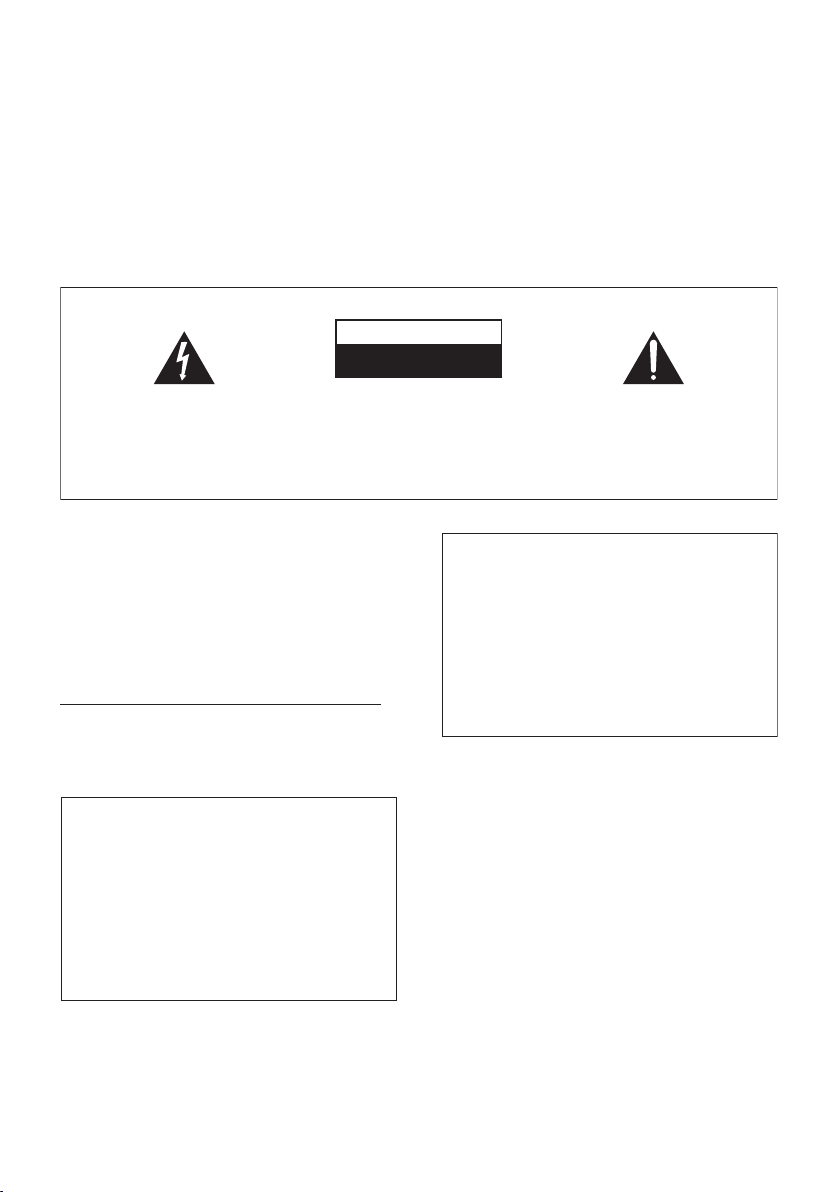
1 Attach the speaker stand bases to the stems
Safety precautions when setting up
When assembling the speakers, lay them down flat on
their side to avoid accidents or injury. Make sure to use a
stable surface when assembling, setting up, and placing
the speakers.
Home theater sound setup (HTP-55)
• This is a standard multichannel surround sound
speaker setup for optimal 5.1 channel home theater
sound.
Front
left
Surround
left
Center
Listening position
Receiver subwoofer
Front
right
Surround
right
using the screws provided.
Once you have aligned the stem and base, secure with
the small screws at the points shown below. Note that
the speaker should face in the direction of the base of the
isosceles triangle (outlined below).
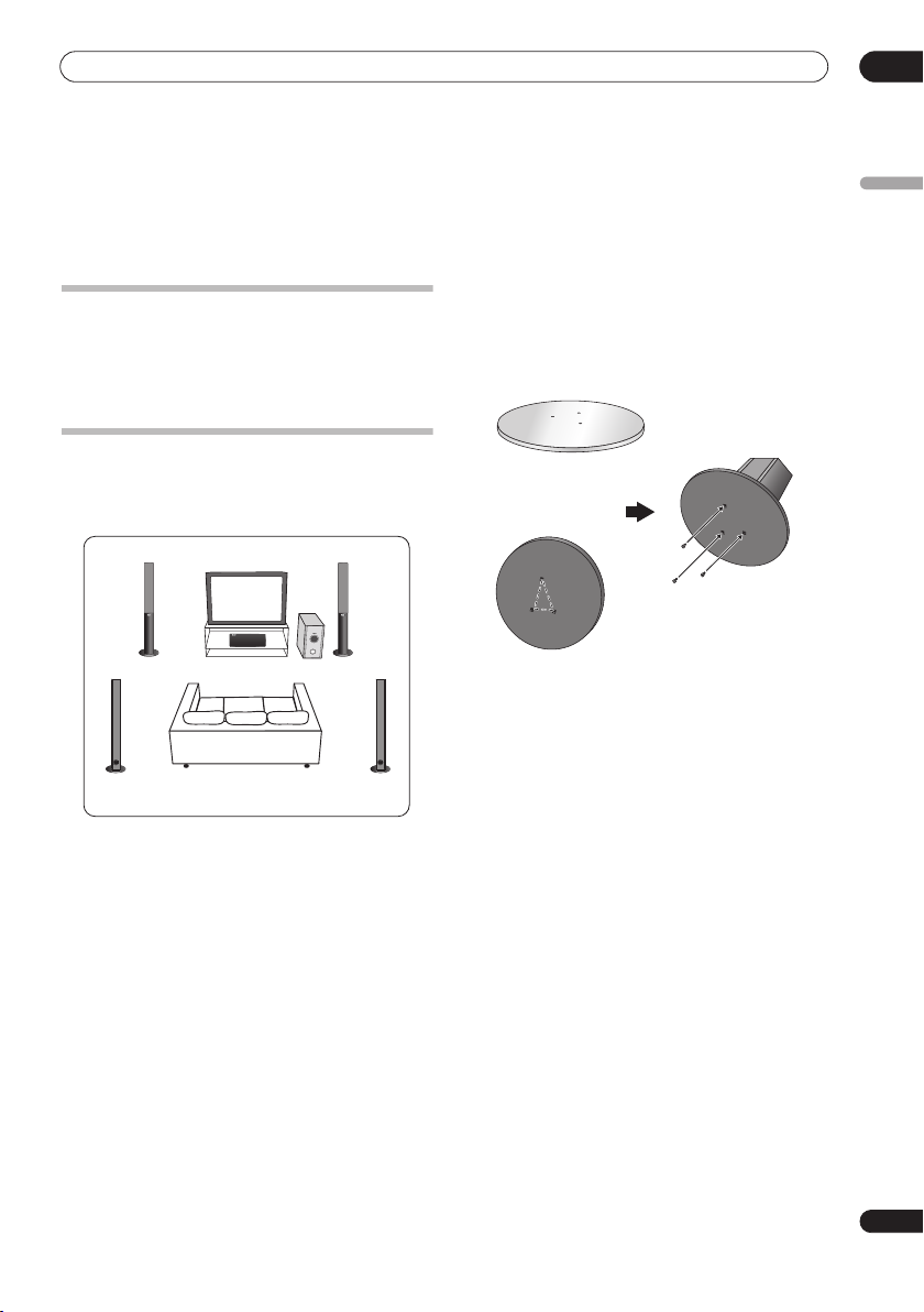
2 Attach the smaller non-skid pads to the base of
the center speaker. The large non-skid pads are for
the front and surround speakers, and the receiver
subwoofer (as shown).
Use the adhesive side of the pads to attach them to the
base (flat surface) of each speaker.
English
Rear
Front
5
En
01
Speaker Setup Guide
Non-skid pads
(small) x 4
Non-skid pads
(large) x 16
Non-skid pads
(large) x 4
Front and Surround speakers
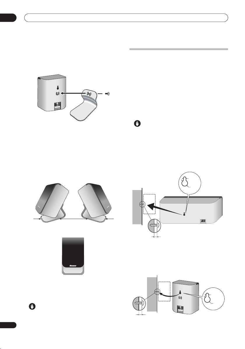
3 Secure each of the front and surround speakers
using the metal catch provided.
Screw two picture hooks or similar into the wall behind
the speaker. Pass a chain or cord around the hooks and
through the metal catch so that the speaker is stabilized
(make sure to test that it supports the weight of the
speaker).
After installing, make sure the speaker is securely fixed.
Center speaker
Receiver subwoofer
Chain or cord
Caution
• The metal catch is not a mounting fixture, and the
speaker should not be hung directly from the wall
using this catch. Always use a chain or cord when
stabilizing the speaker.
• Pioneer disclaims all responsibility for any losses or
damage resulting from improper assembly,
installation, insufficient strength of the installation
materials, misuse, or natural disasters.
4 Connect the speaker system.
Refer to
Connecting up
to connect the speakers properly.
After connecting everything, place the speakers as
shown in the diagram above for optimal surround sound.
After placing the speakers, run the Auto MCACC setup
(page 17) to complete your surround sound setup.
Home theater sound setup (HTP-33)
Depending on the size and characteristics of your room,
you can place your speakers in one of two ways using this
system.
Standard surround setup
This is a standard multichannel surround sound speaker
setup for optimal 5.1 channel home theater sound.
Front
left
Front
right
Metal catch
Surround
left
6
En
Center
Listening position
Listening position
Receiver subwoofer
Surround
right
Speaker Setup Guide
01
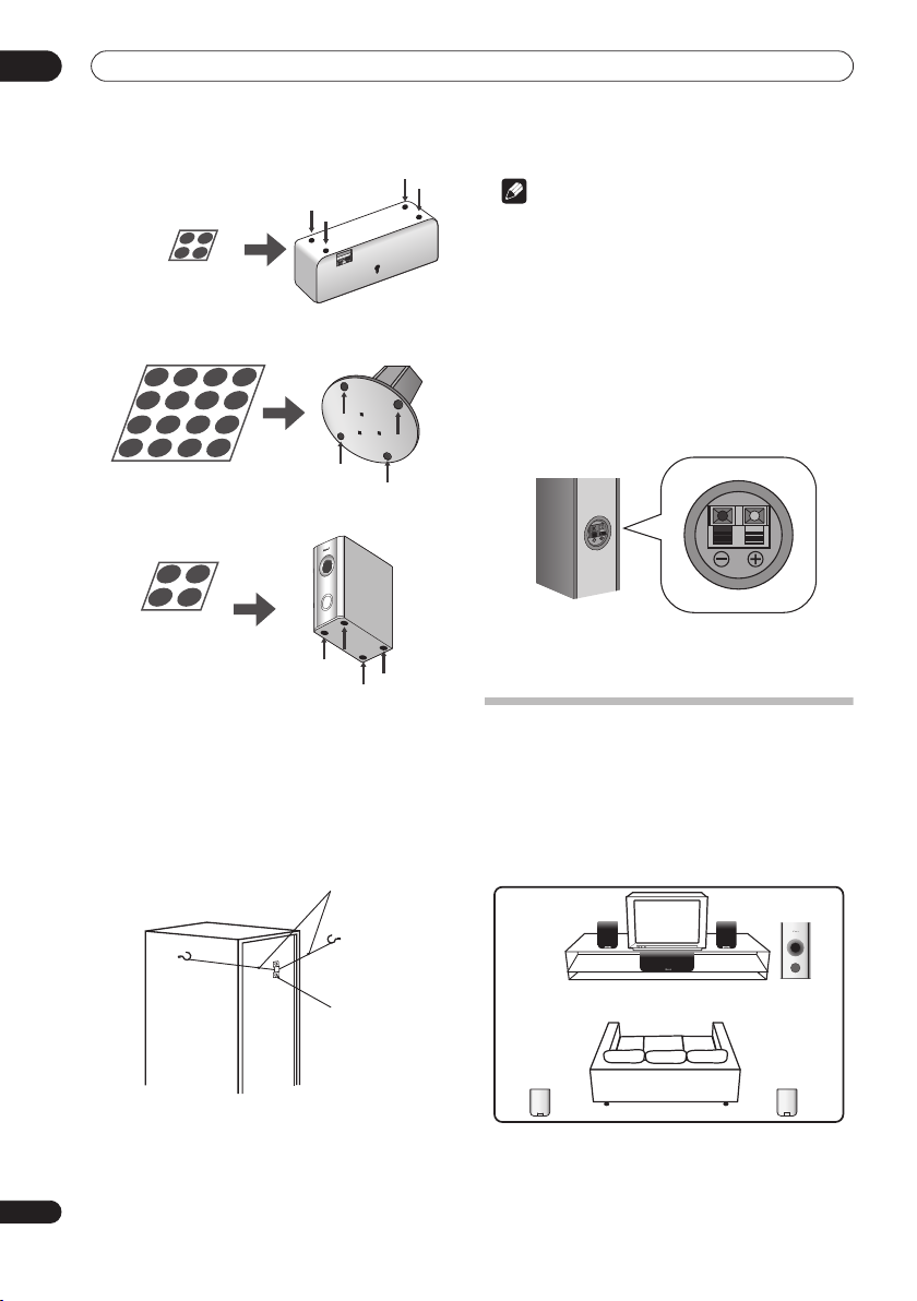
1 Attach the smaller non-skid pads to the base of
each of the front, surround and center speakers. The
four large non-skid pads are for the receiver
subwoofer (as shown).
Use the adhesive side of the pads to attach them to the
base (flat surface) of each speaker.
Front and surround speakers
Non-skid pads
(small) x 20
Center speaker
Non-skid pads
(large) x 4
Front right
Surround
right
subwoofer
Receiver
Surround left
Front left
Center
Listening position
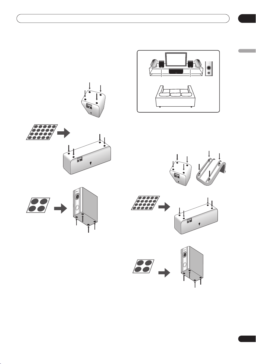
1 Attach the smaller non-skid pads to the base of
the front and center speakers and to the speaker
stands. The four large non-skid pads are for the
receiver subwoofer (as shown).
Use the adhesive side of the pads to attach them to the
base (flat surface) of each speaker or stand.
Speaker stands
Non-skid pads
(small) x 20
Front speakers
English
Receiver subwoofer
2 Connect the speaker system.
Refer to
Connecting up
to connect the speakers properly.
After connecting everything, place the speakers as
shown in the diagram (left) for optimal surround sound.
After placing the speakers, run the Auto MCACC setup
(page 17) to complete your surround sound setup.
Front surround setup
This setup is ideal when rear surround speaker
placement isn't possible or you want to avoid running
long speaker cables in your listening area. Use this setup
together with the Front Surround modes in page 20 to
take advantage of wall and ceiling reflections for a very
realistic surround effect.
Center speaker
Non-skid pads
(large) x 4
Receiver
subwoofer
2 Connect the speaker system.
Refer to
Connecting up
to connect the speakers properly.
After connecting everything, place the speakers as
shown in the diagram (above) for optimal surround
sound (the surround speakers are next to the front
speakers).
7
En
01
Speaker Setup Guide
3 Attach the surround speakers to the speaker
stands.
For each speaker, line up the spurs on the stand with the
holes on the back of the speaker and insert, then secure
the speaker to the stand with the screw provided.
Wall mounting the speakers
Before mounting
• Remember that the speaker system is heavy and that
its weight could cause the screws to work loose, or
the wall material to fail to support it, resulting in the
speaker falling. Make sure that the wall you intend to
mount the speakers on is strong enough to support
them. Do not mount on plywood or soft surface walls.
• Mounting screws are not supplied. Use screws
suitable for the wall material and support the weight
of the speaker.
4 Turn the speakers as shown, following the guide
marks for optimal Front Surround.
If you have selected
or
FRTMUSIC
surround speaker so that the guide markers on the stand
base are lined up horizontally in the direction the
listening position (see below). With
Power), the surround speakers should point in the same
direction as the front speakers (see below).
See
Using Front Surround (HTP-33 only)
more information.
After placing the speakers, run the Auto MCACC setup
(page 17) to complete your surround sound setup.
Caution
• Please don’t attach the surround speakers to the wall
for Front surround setup.
8
En
FRTMOVIE
(Front Surround Music), turn each
FRTMOVIE / FRTMUSIC
(Front Surround Movie)
EXTPOWER
EXTPOWER
on page 20 for
(Extra
Caution
• If you are unsure of the qualities and strength of the
wall, consult a professional for advice.
• Pioneer is not responsible for any accidents or
damage that result from improper installation.
Wall mounting the center speaker
The center speaker has a mounting hole which can be
used to mount the speaker on the wall.
5 mm
10 mm
5 mm to 7 mm
Wall mounting the other speakers (HTP-33)
In addition to the center speaker, the front and surround
speakers also have holes for wall mounting. However, if
you are using the Front Surround setup described on the
previous page, do not wall mount the surround speakers.
5 mm
10 mm
5 mm to 7 mm

Speaker Setup Guide
01
Additional notes on speaker placement
• Install the main front left and right speakers at an
equal distance from the TV.
HTP-33 only:
•
speakers slightly above ear level.
• Install the center speaker above or below the TV so
that the sound of the center channel is localized at
the TV screen.
Precautions:
• When installing the center speaker on top of the TV,
be sure to secure it with tape or some other suitable
means. Otherwise, the speaker may fall from the TV
due to external shocks such as earthquakes,
endangering those nearby or damaging the speaker.
• The front (L/R), center and surround (L/R) speakers
supplied with this system are magnetically shielded.
However, depending on the installation location,
color distortion may occur if the speaker is installed
extremely close to the screen of a television set. If this
happens, turn the power switch of the television set
OFF, and turn it ON after 15 min to 30 min. If the
problem persists, place the speaker system away
from the television set.
• The receiver subwoofer is not magnetically shielded
and so should not be placed near a TV or monitor.
Magnetic storage media (such as floppy discs and
tape or video cassettes) should also not be kept close
to the receiver subwoofer.
•
HTP-55 only:
speakers and receiver subwoofer to the wall or
ceiling. They may fall off and cause injury.
•
HTP-33 only:
the wall or ceiling. They may fall off and cause injury.
• For safety, make sure that there is no exposed bare
speaker wire outside of the speaker terminals.
• Do not connect the supplied speakers with any other
amplifier. This may result in malfunction or fire.
• Do not connect any speakers other than those
supplied to this system.
For optimum effect, install the rear
Do not attach the front, surround
Do not attach the receiver subwoofer to
English
9
En

02
Connecting up
Chapter 2
Connecting up
Basic connections
Important
• When connecting this system or changing connections, be sure to switch power off and disconnect the power
cord from the wall socket.
After completing all connections, connect the power cord to the wall socket.
Receiver subwoofer
3
FM antenna
AM loop antenna
2
10
En
ANTENNA
CONTROL IN
MCACC
SYSTEM CONNECTOR
USE ONLY WITH
DISPLAY UNIT
SETUP MIC
CONTROL
SPEAKERS
OUT
SUB WOOFER
CENTER
AC IN
SURROUND
RL
FRONT
RL
DVD/DVR 1
(COAXIAL)
FM
UNBALAMLOOP ANTENNA75Ω
DIGITAL
DVD/DVR 2
(OPTICAL)
AUDIO INPUT
(OPTICAL)
DIGITAL
ANALOG
L
R
Note
• When using the display unit in a wall-mounted
location, take full precautions to prevent the unit
from accidentally falling.
• Screws and other fixtures for use in wall mounting
are not included.
Display unit
1
Display cable
WARNING
• Pioneer bears no responsibility for accidents
resulting from faulty assembly or installation,
insufficient mounting strength of walls, mounting
fixtures (or other building fixtures), misuse or natural
disasters.
Connecting up
02
1 Connect the display unit to the receiver subwoofer.
Plug the L-shaped end of the display cable into the
connector on the rear of the display unit, then plug the
other end of the display cable into
CONNECTOR
jack on the receiver subwoofer.
SYSTEM
2 Assemble the AM loop antenna.
a
b
c
a. Bend the stand in the direction indicated by the
arrow.
b. Clip the loop onto the stand.
c. If you want to fix to a wall or other surface, perform
step b after first securing the stand with screws.
It is recommended that you determine the reception
strength before securing the stand with the screws.
3 Connect the AM and FM antennas1.
a. Connect one wire of the AM loop antenna to each AM
antenna terminal
2
.
For each terminal, press down on the tab to open;
insert the wire, then release to secure.
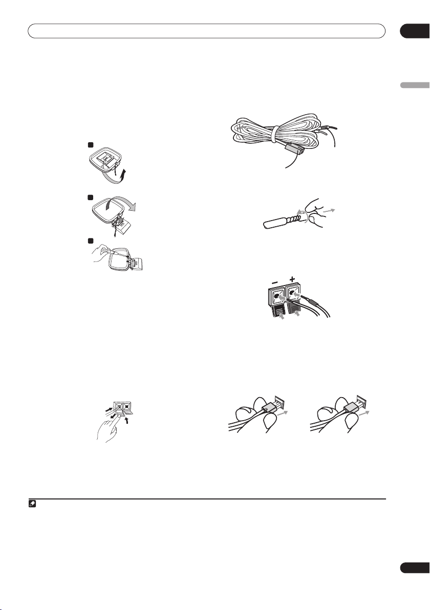
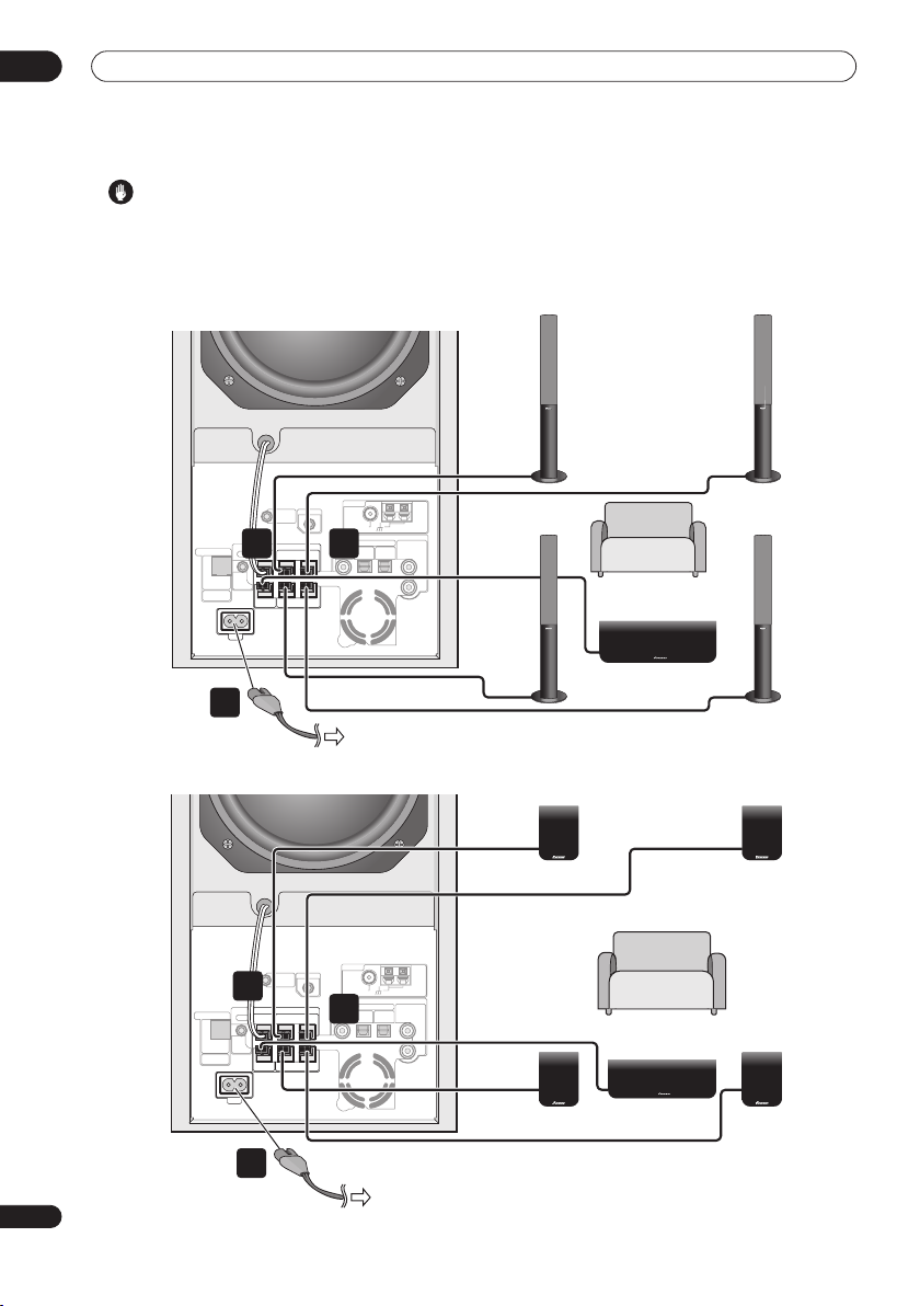
4 Connect each speaker.
• Each speaker cable has a color-coded connector at
one end and two wires at the other end.
Color-coded wire
Color-coded connector
(Connect to rear panel)
(Connect to speaker)
• Twist and pull off the protective shields on each wire.
• Connect the wires to the speaker. Match the colored
wired with the color-coded label (model label), then
+
insert the colored wire into the red (
other wire into the black (
–
) side.
) side and the
• Connect the other end to the color-coded speaker
terminals on the rear of the receiver subwoofer. Make
sure to insert completely.
The small lug at the wire-end of the speaker plug
should face up or down depending on whether it’s
being plugged into one of the upper or lower speaker
terminals. Please make sure to connect correctly.
English
1
2
3
b. Push the FM antenna
plug onto the center pin of the
FM antenna socket.
Note
1• Keep antenna cables away from other cables, the display unit and receiver subwoofer.
• If reception with the supplied antenna is poor, see
external antennas
2• Don’t let it come into contact with metal objects and avoid placing near computers, television sets or other electrical appliances.
• The signal earth () is designed to reduce noise that occurs when an antenna is connected. It is not an electrical safety earth.
• If radio reception is poor, you may be able improve it by re-inserting each antenna wire into the opposite terminal.
• For best reception, do not untwist the AM loop antenna wires or wrap them around the loop antenna.
3 To ensure optimum reception, make sure the FM antenna is fully extended and not coiled or hanging at the rear of the unit.
on page 27.
Improving poor FM reception
Upper terminal Lower terminal
5 Connect the subwoofer cable.
• Just below the subwoofer speaker, to the left of
center, you should see the subwoofer connecting
cable. Plug this into the
SUBWOOFER SPEAKER
terminal.
and
Improving poor AM sound
on page 23 or
Connecting
11
En
02
Connecting up
Caution
• These speaker terminals carry
voltage
. To prevent the risk of electric shock when
HAZARDOUS LIVE
connecting or disconnecting the speaker cables,
disconnect the power cord before touching any
uninsulated parts.
Receiver subwoofer (SX-SW505)
ANTENNA
CONTROL IN
MCACC
SYSTEM CONNECTOR
USE ONLY WITH
DISPLAY UNIT
SETUP MIC
CONTROL
SPEAKERS
5 4
OUT
SUB WOOFER
CENTER
AC IN
SURROUND
RL
FRONT
RL
DVD/DVR 1
FM
UNBALAMLOOP ANTENNA75Ω
DIGITAL
DVD/DVR 2
(OPTICAL)
AUDIO INPUT
DIGITAL
(OPTICAL)
7
To AC outlet
Receiver subwoofer (SX-SW303)
• Do not connect any speakers other than those
supplied to this system.
• Do not connect the supplied speakers to any
amplifier other than the one supplied with this
system. Connection to any other amplifier may result
in malfunction or fire.
Surround right
(Gray)
ANALOG
L
R
Listening position
Center (Green)
Front right
Red)
(
Surround left
(Blue)
Front left
(White)
Speaker system (S-TA505)
12
En
SYSTEM CONNECTOR
USE ONLY WITH
DISPLAY UNIT
Surround right
(Gray)
ANTENNA
CONTROL IN
MCACC
SETUP MIC
5
CONTROL
SPEAKERS
OUT
SUB WOOFER
CENTER
AC IN
7
SURROUND
RL
FRONT
RL
DVD/DVR 1
4
FM
UNBALAMLOOP ANTENNA75Ω
DIGITAL
DVD/DVR 2
(OPTICAL)
AUDIO INPUT
DIGITAL
(OPTICAL)
ANALOG
L
R
Front right
(Red)
Listening position
Center (Green)
Speaker system (S-ST303)
Surround left
(Blue)
Front left
(White)
To AC outlet

Connecting up
02
6 If you have a DVD player or other source1
component you want to connect, connect it now before
connecting the power cord in the next step.
See
Connecting auxiliary components
to connect a digital source component. See also
this system for TV audio
below to connect a TV.
7 Connect the power cord.
on page 27 for how
Using
2
• Connect the power cord to AC inlets on the receiver
subwoofer. Connect the power cord to a wall socket.
Using this system for TV audio
If your TV has a stereo audio output you can connect it to
this system and enjoy surround TV sound.
AUDIO INPUT
CONTROL
SYSTEM CONNECTOR
OUT
SUB WOOFER
USE ONLY WITH
DISPLAY UNIT
CENTER
AC IN
1 Connect the AUDIO OUTPUT jacks on your TV to the
ANALOG AUDIO INPUT jacks on the receiver subwoofer.
Use the red/white stereo audio cable (not supplied) for
this connection. Make sure you match the left and right
outputs with their corresponding inputs for correct
stereo sound.
• You can use the
analog source you want, such as a tape deck, etc.
DIGITAL
SPEAKERS
DVD/DVR 1
DIGITAL
DVD/DVR 2
SURROUND
RL
FRONT
RL
ANALOG
(COAXIAL)
(OPTICAL)
(OPTICAL)
L
R
ANALOG AUDIO INPUT
1
AUDIO
OUTPUT
TV
jacks for any
English
Note
1 Make sure to connect a TV or monitor (for video sources) to take advantage of this system’s home theater potential. Please refer to the instruc-
tion manual supplied with your TV or monitor for connection details.
2• Do not use any power cord other than the one supplied with this system.
• Do not use the supplied power cord for any purpose other than connecting to this system.
13
En
03
Controls and displays
Chapter 3
Controls and displays
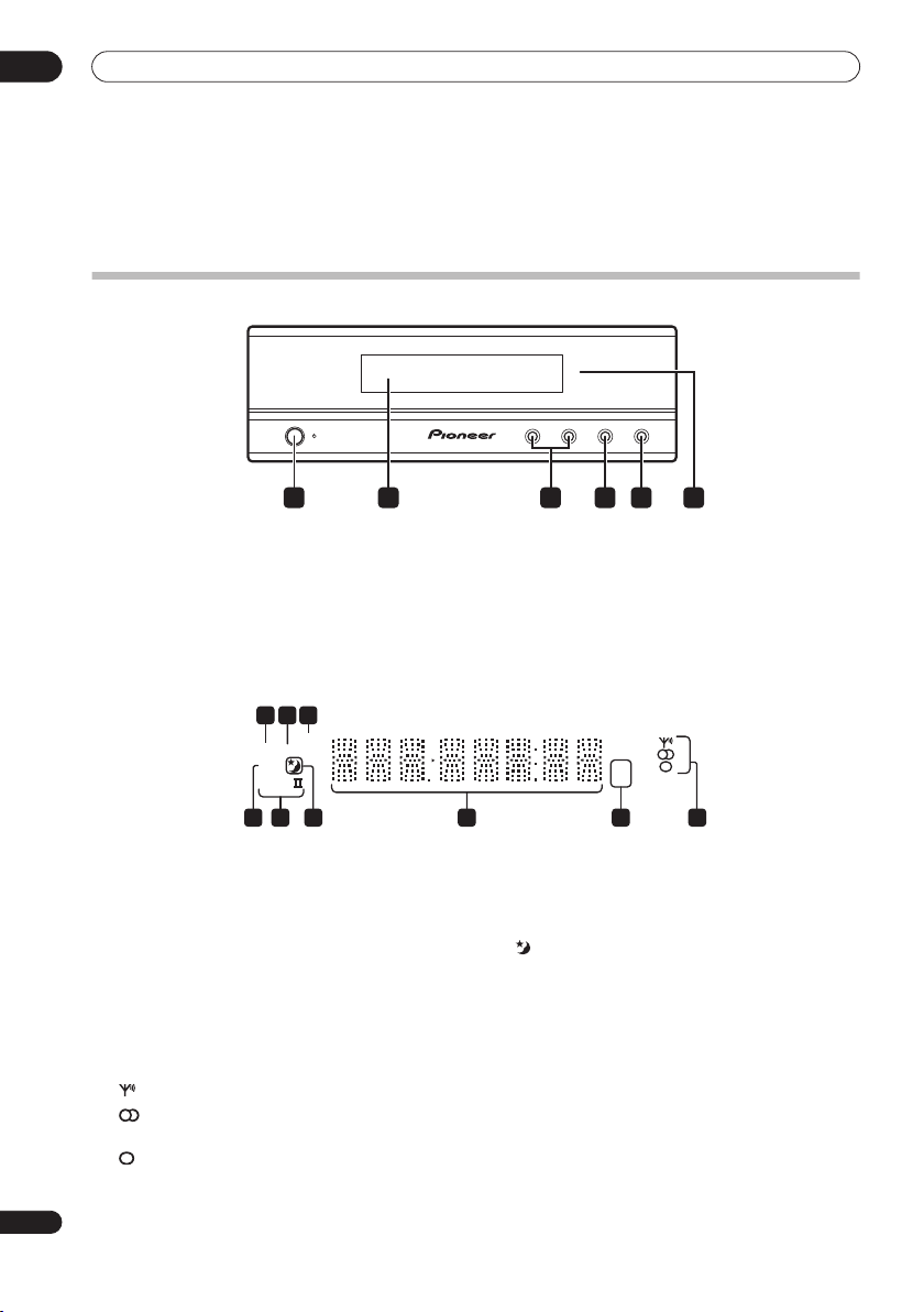
Display unit
STANDBY/ON
1 4 652 3
1
STANDBY/ON
Press to switch the system on/into standby.
2 Front panel display
See below for details.
3
VOLUME
Use to adjust the volume.
buttons
Display
2 3
1
SOUND
DTS F.SURR.
2D
2PL
789
1
DTS
Lights during playback of a DTS source (page 19).
2
F.SURR. (HTP-33 only)
Lights when one of the Front Surround listening
modes is selected (page 20).
SURR.
Lights when one of the Advanced Surround listening
modes is selected (page 20).
3 SOUND
Lights when Sound Retriever is active (page 20).
4 Tuner indicators
– Lights when a broadcast is being received.
– Lights when a stereo FM broadcast is being
received in auto stereo mode.
– Lights when FM mono reception is selected.
– VOLUME + AUDIO INPUT SURROUND
4
AUDIO INPUT (page 27)
Press repeatedly to select one of the external audio
inputs (
DVD/DVR1, DVD/DVR2, DIGITAL
5
SURROUND
Use to select a Surround mode (page 19).
6 IR remote sensor
6
5 kHz / MHz
Indicates the frequency unit shown in the character
display (
6 Character display
7
Lights when sleep timer is active (page 30).
82 PL II
Lights during Dolby Pro Logic II decoding (page 19).
92 D
Lights during playback of a Dolby Digital source
(page 19).
kHz
for AM,
(page 16)
kHz
MHz
5 4
MHz
for FM).
or
ANALOG
).
14
En

Controls and displays
03
Remote control
STANDBY/ON
DVD/DVR1DVD/DVR
ENTER
SETUP
ST
SOUND
SOUND
RETRIEVER
CHANNEL
TV
DVD/DVR1
DVD/DVR2
DIGITAL
ANALOG
23)
VOLUME
TUNE
ENTER
TUNE
TV CONTROL
RECEIVER
MUTE
2DIGITAL
ANALOG
FM /AM
SLEEP
CLEAR
SR
ST
TEST
TONE
MCACCADVANCEDSURROUND
VOLUME
INPUT
digital audio input.
digital audio input.
audio input.
audio inputs.
3
6
8
11
14
15
1
2
4
5
7
9
10
12
13
16
1
STANDBY/ON
Press to switch the receiver subwoofer on or into standby.
2
MUTE
Press to mute all audio from the speakers. Press again to
cancel and restore the sound.
3
VOLUME
+/–
Use to adjust the volume.
4 Input select buttons
DVD/DVR1
Press to select the
DVD/DVR2
Press to select the
DIGITAL
Press to select the
ANALOG
Press to select the
FM/AM
(page 28)
(page
Press to select the built-in radio tuner.
5 Number buttons, CLEAR and ENTER
Use the number buttons for entering radio stations
directly, and so on.
Use
CLEAR to clear an entry and start again.
ENTER to confirm an entry.
Use
6
SLEEP
Press to set the sleep timer (page 30).
7
SETUP
Use to access the menu system for surround sound
setup, tuner settings and so on (page 17, 23, 24, 25, 30).
8 SR+
Use to setup the SR+ features and to select the SR+
mode (page 29).
9
///
(cursor buttons) and
ENTER
Use to navigate the receiver subwoofer menus.
10
SOUND
(page 22)
Press to access the sound menu, from which you can
adjust bass and treble, etc.
11
TEST TONE
Use to output the test tone (for speaker setup) (page 26).
12 SOUND RETRIEVER
Press to restore CD quality sound to compressed stereo
audio sources (page 21).
13
SURROUND
Use to select a Surround mode (page 19).
14
ADVANCED
Use to select a Pioneer original surround mode (page 21).
15
MCACC
Starts the Auto MCACC setup (page 17).
16 TV CONTROL
(page 31)
After setting up, use these controls to control your TV.
English
15
En

03
Controls and displays
Using the remote control
Please keep in mind the following when using the remote
control:
• Make sure that there are no obstacles between the
remote and the remote sensor on the unit.
• Remote operation may become unreliable if strong
sunlight or fluorescent light is shining on the unit’s
remote sensor.
• Remote controllers for different devices can interfere
with each other. Avoid using remotes for other
equipment located close to this unit.
• Replace the batteries when you notice a fall off in the
operating range of the remote.
• Use within the operating range in front of the remote
control sensor on the display unit, as shown.
30
30
7 m
Putting the batteries in the remote
control
1 Open the battery compartment cover on the back of
the remote control.
2 Insert two AA/R6 batteries into the battery
compartment following the indications (
the compartment.
,
• Remove batteries from equipment that isn’t going to
be used for a month or more.
• When disposing of used batteries, please comply
with governmental regulations or environmental
public instruction’s rules that apply in your country or
area.
WARNING
• Do not use or store batteries in direct sunlight or
other excessively hot place, such as inside a car or
near a heater. This can cause batteries to leak,
overheat, explode or catch fire. It can also reduce the
life or performance of batteries.
) inside
16
En
3 Close the cover.
Caution
Incorrect use of batteries can result in hazards such
as leakage and bursting. Please observe the
following:
• Don’t mix new and old batteries together.
• Don’t use different kinds of battery together—
although they may look similar, different batteries
may have different voltages.
• Make sure that the plus and minus ends of each
battery match the indications in the battery
compartment.

Getting started
04
Chapter 4
Getting started
System demo setting
Switches the automatic demo feature on or off (this
starts when you plug in for the first time).
ENTER
SETUP
SOUND
SOUND
RETRIEVER
1Switch the system into standby.
2 Press
SETUP
.
3 Use the
/
(cursor left/right) buttons to select
DEMO from the menu, then press
/
4 Use the
setting, then press
(cursor up/down) buttons to select a
ENTER
Select from:
DEMO ON
•
•
DEMO OFF
– Switches the demo display on.
– Switches the demo display off and the
system into standby.
SLEEP
CLEAR
SR
TUNE
ST
ST
ENTER
TEST
TONE
TUNE
MCACCADVANCEDSURROUND
ENTER
.
.
Using the Auto MCACC setup for
optimal surround sound
The Multichannel Acoustic Calibration (MCACC) system
measures the acoustic characteristics of your listening
area, taking into account ambient noise, and testing for
channel delay and channel level. After you have set up
the microphone provided, the system uses the
information from a series of test tones to optimize the
speaker settings and equalization (Acoustic Calibration
EQ) for your particular room.
Important
• The test tones used for Auto MCACC setup are loud;
however, do not turn the volume down during setup
as this may result in a sub-optimal setup.
• Make sure the microphone and speakers are not
moved during the MCACC setup.
STANDBY/ON
MUTE
VOLUME
DVD DTV
PC/GAME
1 Connect the microphone to the MCACC SETUP MIC
jack on the rear panel.
1
SETUP
SOUND
SOUND
AUX
TUNER
RETRIEVER
CHANNEL
SR
TUNE
ST
ST
ENTER
TEST
TONE
TUNE
MCACCADVANCEDSURROUND
VOLUME
English
MCACC
SETUP MIC
ANTENNA
CONTROL IN
MCACC
SETUP MIC
FM
UNBALAMLOOP ANTENNA
75Ω
AUDIO INPUT
SYSTEM CONNECTOR
CONTROL
OUT
USE ONLY WITH
DISPLAY UNIT
AC IN
DIGITAL
SPEAKERS
DVD/DVR 1
DIGITAL
DVD/DVR 2
SURROUND
SUB WOOFER
RL
CENTER
FRONT
RL
ANALOG
(COAXIAL)
(OPTICAL)
(OPTICAL)
L
R
2 Place the microphone at your normal listening
position.
Place it about ear height, and make sure it is level by
using a table or chair.
Make sure there are no obstacles between the speakers
and the microphone.
Note
1 You only need to use the Auto MCACC setup once (unless you change the placement of your speakers or your room layout).
17
En

04
Getting started
3 If the receiver subwoofer is off, press
ON
to turn the power on.
MCACC
4 Press
.
Try to be as quiet as possible after pressing
STANDBY/
MCACC
. The
volume increases automatically and the system outputs
a series of test tones.
• To cancel Auto MCACC setup before it has finished,
press
MCACC
. The unit will continue to use the
previous settings.
• If the ambient noise level is too high,
the display for five seconds. To exit and check the
noise levels
ENTER
• If you see an
when
1
, press
MCACC
RETRY
shows in the display.
ERR MIC
or
ERR SP
NOISY
blinks in
, or to try again, press
message in the
display, there may be a problem with your mic or the
speaker connections. To try again, press
when you see
RETRY2.
ENTER
When the MCACC setup is complete, the volume level
returns to normal,
Acoustic Calibration EQ is activated.
COMPLETE3 shows in the display, and
4
Note
1• If the room environment is not optimal for the Auto MCACC setup (too much ambient noise, echo off the walls, obstacles blocking the speakers from
the microphone) the final settings may be incorrect. Check for household appliances (air conditioner, fridge, fan, etc.), that may be affecting the environment and switch them off if necessary.
• Some older TVs may interfere with the operation of the mic. If this seems to be happening, switch off the TV during Auto MCACC setup.
18
En
2 If this doesn’t work, press
3 If
COMPLETE
4 See
Listening with Acoustic Calibration EQ
MCACC
doesn’t appear, it is likely an error occurred during the setup. Please check all connections and try again.
, turn off the power, and check the problem indicated by the
on page 21 to switch on/off Acoustic Calibration EQ.
ERR
message, then try the Auto MCACC setup again.
Listening to your system
05
Chapter 5
Listening to your system
Auto listening mode
The Auto listening mode is the simplest way to listen to
any source as it was mastered: the output from the
speakers mirrors the channels in the source material.
HTP-33 only:
(page 7), the Front Surround modes will give the best
results (see
page 20).
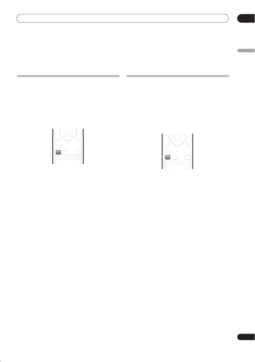
• Press
mode.
If the source is Dolby Digital or DTS, the front panel 2 D
or
• You can also use the
If you set up the system for Front surround
Using Front Surround (HTP-33 only)
ST
ST
ENTER
TUNE
VOLUME
CHANNEL
SURROUND
TEST
TONE
MCACCADVANCEDSURROUND
INPUT
button on the
SURROUND
DTS
indicator lights.
SOUND
SOUND
RETRIEVER
TV
to select the AUTO listening
display unit to change the listening mode.
on
Listening in surround sound
You can listen to stereo or multichannel sources in
surround sound. Surround sound is generated from
stereo sources using one of the Dolby Pro Logic
decoding modes.
HTP-33 only:
(page 7), the Front Surround modes will give the best
results (see
page 20).
• Press
mode.
• You can also use the
The choices that appear in the display will vary according
to the type of source that’s playing.
If the source is Dolby Digital or DTS, the front panel
or
DTS
•
•
•
•
•
If you set up the system for Front surround
Using Front Surround (HTP-33 only)
SURROUND
display unit to change the listening mode.
indicator lights.
AUTO
– Auto listening mode (see above)
DOLBY PL
(Dolby Pro Logic) – 4.1 channel surround
sound for use with any two-channel source
MOVIE
(Dolby Pro Logic II Movie) – 5.1 channel
surround sound, especially suited to movie sources,
for use with any two-channel source
MUSIC
(Dolby Pro Logic II Music) – 5.1 channel
surround sound, especially suited to music sources,
for use with any two-channel source; see
Logic II Music settings
STEREO
– See
Listening in stereo
on
ST
ST
ENTER
SOUND
RETRIEVER
SOUND
CHANNEL
TV
TEST
TONE
TUNE
MCACCADVANCEDSURROUND
VOLUME
INPUT
repeatedly to select a listening
SURROUND
button on the
2
Dolby Pro
below
on page 21
English
D
19
En
05
Listening to your system
Dolby Pro Logic II Music settings
When listening in Dolby Pro Logic II Music mode (see
above), there are three settings you can adjust: Center
Width, Dimension, and Panorama.
SLEEP
ENTER
CLEAR
SETUP
SOUND
SOUND
RETRIEVER
1With Dolby Pro Logic II Music mode active, press
SOUND
.
2 Use
/
(cursor left/right) to select C WIDTH,
DIMEN. or PANORAMA then press
•
C WIDTH
(Center Width): Provides a better blend of
the front speakers by spreading the center channel
between the front right and left speakers, making it
sound wider (higher settings) or narrower (lower
settings).
•
DIMEN.
(Dimension): Adjusts the depth of the
surround sound balance from front to back, making
the sound more distant (minus settings), or more
forward (positive settings).
•
PANORAMA
: Extends the front strereo image to
include the surround speakers for a ‘wraparound’
effect.
3 Use
/
then press
(cursor up/down) to adjust the setting
ENTER
to confirm.
SR
TUNE
ST
ST
ENTER
TEST
TONE
TUNE
MCACCADVANCEDSURROUND
ENTER
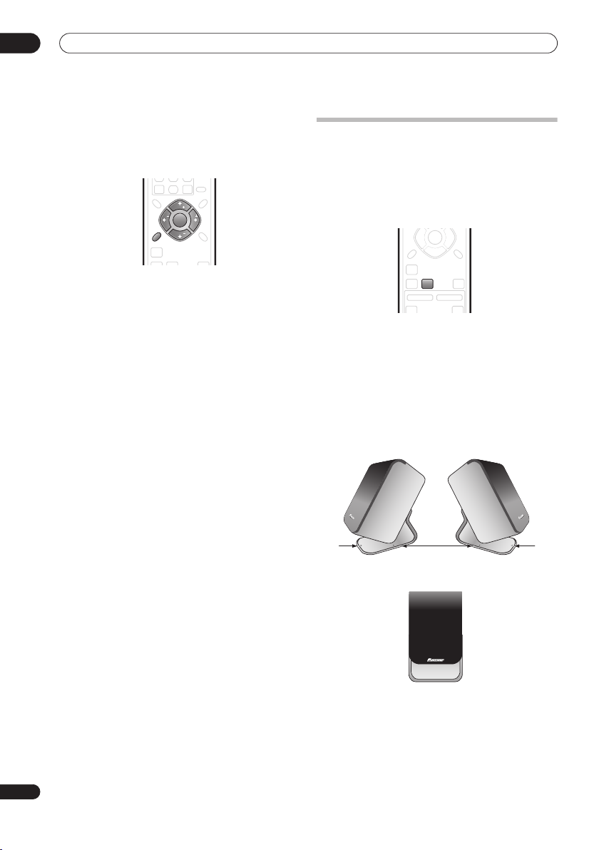
Using Front Surround (HTP-33 only)
The Front Surround modes are effective when you are
using the Front surround speaker setup as described on
page 7. The surround speakers should be placed beside
the front speakers and oriented either towards the walls,
or straight ahead, depending on which mode you are
using (see below).
ST
ST
ENTER
SOUND
SOUND
RETRIEVER
TV
.
• Press
ADVANCED
to select a Front Surround mode.
Press repeatedly to select
EXTPOWER
.
• If you have selected
Movie) or
FRTMUSIC
each surround speaker so that the guide markers on
the stand base are lined up horizontally in the
direction the listening position (see below). With
EXTPOWER
(Extra Power), the surround speakers
should point in the same direction as the front
speakers (see below).
TEST
TONE
TUNE
MCACCADVANCEDSURROUND
VOLUME
CHANNEL
INPUT
FRTMOVIE, FRTMUSIC
FRTMOVIE
(Front Surround
(Front Surround Music), turn
or
20
En
FRTMOVIE / FRTMUSIC
EXTPOWER
Listening to your system
05
Using Advanced Surround
The Advanced Surround effects can be used with any
multichannel or stereo source for a variety of additional
surround sound effects.
HTP-33 only:
If you set up the system for Front surround
(page 7), the Front Surround modes will give the best
results (see
• Press
Using Front Surround (HTP-33 only)
ST
ST
ENTER
CHANNEL
TEST
TONE
TUNE
MCACCADVANCEDSURROUND
VOLUME
INPUT
ADVANCED
SOUND
SOUND
RETRIEVER
TV
to select an Advanced Surround
above).
mode.
Press repeatedly to select:
ADVMOVIE
•
ADVMUSIC
•
EXPANDED
•
•
TV SURR.
– Suitable for movies
– Suitable for music
– Wide sound field
– Surround sound for mono or stereo TV
broadcasts
SPORTS
•
•
•
– Suitable for sports programming
GAME
– Suitable for TV game units
VIRTUAL
– A virtual surround effect using just the
subwoofer and front speakers.
•
5 STEREO
– Powerful surround sound for stereo
music sources
Listening in stereo
You can listen to any source—stereo or multichannel—in
stereo. When playing a multichannel source, all
channels are downmixed to the front left/right speakers
and the subwoofer.
TUNE
VOLUME
CHANNEL
TV CONTROL
SURROUND
TEST
TONE
MCACCADVANCEDSURROUND
INPUT
button on the
SOUND
SOUND
RETRIEVER
TV
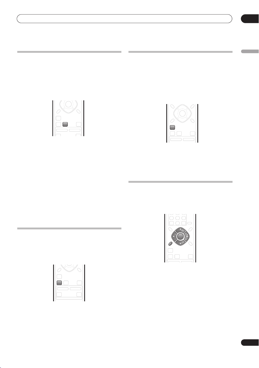
• Press
SURROUND
repeatedly until STEREO shows in
the display.
• You can also use the
display unit to change the listening mode.
Using the Sound Retriever
When audio data is removed during the MP3 or WMA
compression process, sound quality often suffers from
an uneven sound image. The Sound Retriever feature
employs new DSP technology that helps bring CD quality
sound back to compressed 2-channel audio by restoring
sound pressure and smoothing jagged artifacts left over
after compression.
TUNE
ST
ST
ENTER
SOUND
SOUND
RETRIEVER
CHANNEL
•While listening to a stereo source, press
RETRIEVER
.
TEST
TONE
TUNE
MCACCADVANCEDSURROUND
VOLUME
SOUND
Press repeatedly to switch between:
RTRV ON
•
•
— Switches the Sound Retriever on.
RTRV OFF
— Switches the Sound Retriever off.
Listening with Acoustic Calibration EQ
You can listen to sources using the Acoustic Calibration
EQ set in
Using the Auto MCACC setup for optimal
surround sound
1 Press
2 Use the
MCACC EQ then press
3 Use the
EQ ON or EQ OFF then press
• On the
speaker settings (channel delay and channel level)
remains as it is set.
• Acoustic Calibration EQ is set to on automatically
after Auto MCACC setup is used.
on page 17.
SLEEP
ENTER
CLEAR
SETUP
SOUND
SOUND
RETRIEVER
CHANNEL
SOUND
.
/
(cursor left/right) buttons to select
ENTER
/
(cursor up/down) buttons to switch
EQ OFF
setting, equalization is set to off and
SR
TUNE
ST
ST
ENTER
TEST
TONE
TUNE
MCACCADVANCEDSURROUND
VOLUME
.
ENTER
to confirm.
English
21
En
 Loading...