

Page 1

Installation Manual
SPH-DA210
SPH-DA110
A
ppRadio
Page 2
Connecting the system Connecting the system
Pr
ecautions before
connecting the system
W
ARNING
Do not take any steps to tamper with or
disable the parking brake interlock system which is in place for your protection. Tampering with or disabling the
parking brake interlock system could
result in serious injury or death.
CA
UTION
• If you decide to perfor
m the installation yourself, and have special training
and experience in the mobile electronics installations, please carefully follow all of the steps in the installation
manual.
• Secure all wiring with cable clamps or
electrical tape. Do not allow any bare
wiring to remain exposed.
• Do not directly connect the yellow lead
of this product to the vehicle battery. If
the lead is directly connected to the
battery, engine vibration may eventually cause the insulation to fail at the
point where the wire passes from the
passenger compartment into the
engine compartment. If the yellow
lead’s insulation tears as a result of
contact with metal parts, short-circuiting can occur, resulting in considerable
danger.
• It is extremely dangerous to allow
cables to become wound around the
steering column or shift lever. Be sure
to install this product, its cables, and
wiring away in such so that they will
not obstruct or hinder driving.
• Make sure that the cables and wires
will not interfere with or become
caught in any of the vehicle’s moving
parts, especially the steering wheel,
shift lever, parking brake, sliding seat
tracks, doors, or any of the vehicle’s
controls.
• Do not route wires where they will be
exposed to high temperatures. If the
insulation heats up, wires may become
damaged, resulting in a short circuit or
malfunction and permanent damage to
the product.
• Do not cut the GPS antenna cable to
shorten it or use an extension to make
it longer. Altering the antenna cable
could result in a short circuit or malfunction.
• Do not shorten any leads. If you do, the
protection circuit (fuse holder, fuse
resistor or filter, etc.) may fail to work
properly.
• Never feed power to other electronic
products by cutting the insulation of
the power supply lead of this product
and tapping into the lead. The current
capacity of the lead will be exceeded,
causing overheating.
B
efore installing this product
• Use this unit with a 12-volt batter
y and
negative grounding only. Failure to do so
may result in a fire or malfunction.
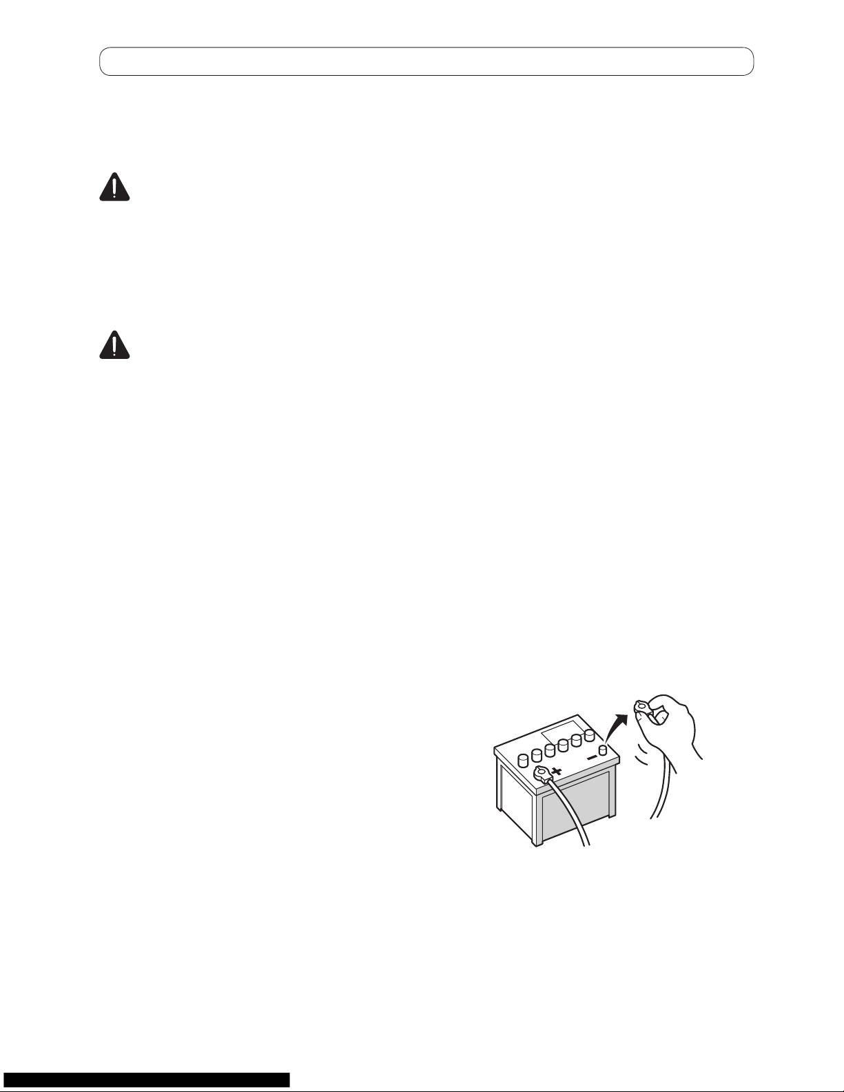
T
o avoid shorts in the electrical system, be
sure to disconnect the (−) battery cable before installation.
Page 3
T
o prevent damage
W
ARNING
• Use speak
ers over 50 W (output value)
andbetween4Ωto8Ω(impedance
value).Donotuse1Ωto3Ωspeak
ers
for this unit.
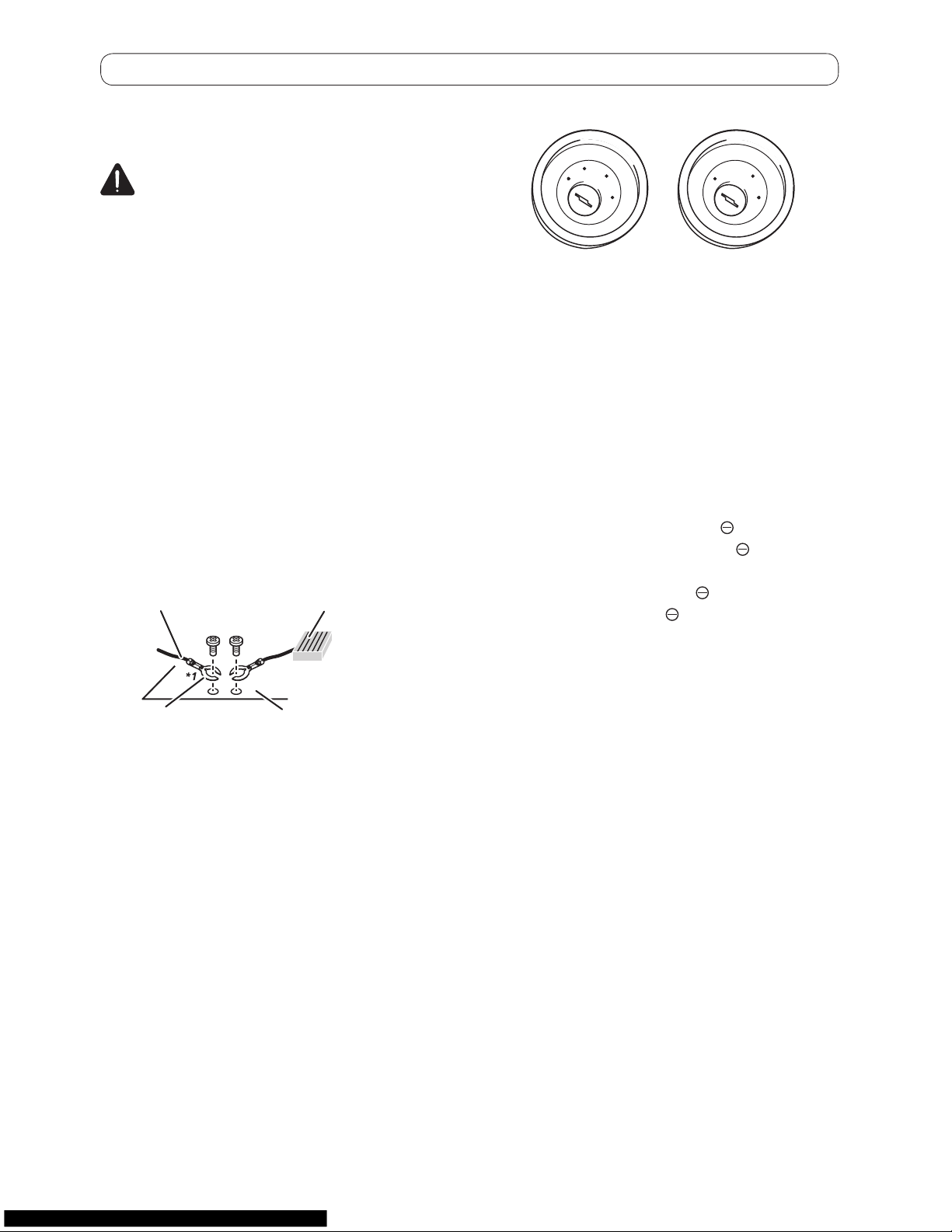
• The black cable is ground. When
installing this unit or power amp (sold
separately), make sure to connect the
ground wire first. Ensure that the
ground wire is properly connected to
metal parts of the car’s body. The
ground wire of the power amp and the
one of this unit or any other device
must be connected to the car separately with different screws. If the
screw for the ground wire loosens or
falls out, it could result in fire generation of smoke or malfunction.
Ground wire P
ower amp
Other devices
(Another electronic
device in the car)
*1
Not supplied for this unit.
Metal parts of car’s body
• When r
eplacing the fuse, be sure to
only use a fuse of the rating prescribed
on this product.
• When disconnecting a connector
, pull
the connector itself. Do not pull the
lead, as you may pull it out of the connector.
• This product cannot be installed in a
vehicle without ACC (accessory) position on the ignition switch.
A
C
C
O
N
S
T
A
R
T
O
F
F
O
N
S
T
A
R
T
O
F
F
ACC position No ACC position
• T
o avoid short-circuiting, cover the disconnected lead with insulating tape. It is
especially important to insulate all unused speaker leads, which if left uncovered may cause a short circuit.
• Refer to the owner’s manual for details
on connecting the power amp and other
units, then make connections accordingly.
• Since a unique BPTL circuit is employed,
do not directly ground the
side of the
speaker lead or connect the
side of an-
other side of the speaker lead together
.
Be sure to connect the
side of the
speaker lead to the
side of the speaker
lead on this product.
Notice for the blue/white lead
• When the ignition switch is turned on
(ACC ON), a control signal is output
through the blue/white lead. Connect to
an external power amp’s system remote
control terminal (max. 300 mA 12 V DC).
The control signal is output through the
blue/white lead, even if the A
V source is
switched off.
• Be sure not to use this lead as the power
supply lead for the external power amps.
Such connection could cause excessive
current drain and malfunction.
• Be sure not to use this lead as the power
supply lead for the auto-antenna or antenna booster. Such connection could
cause excessive current drain and malfunction.
Page 4

Connecting the system Connecting the system
P
arts supplied
This product P
ower cord
GPS antenna Microphone
HDMI cable holder
Installing the HDMI® cable holder
1 Insert the lower tab of the HDMI cable holder into the gr
oove of this prod-
uct.
Ta
b
Groove
2 Insert the two upper tabs into the
this pr
oduct by pushing the HDMI ca-
ble holder.
T
abs
p Use the HDMI cable holder when you con-
nect this product with the separately sold
HDMI/USB inter
face cable for iPod /
iPhone (CD-IH202) or App Connectivity Kit
(CD-AH200).
p
Never grip the holder tightly or use force
when removing or attaching.
Page 5
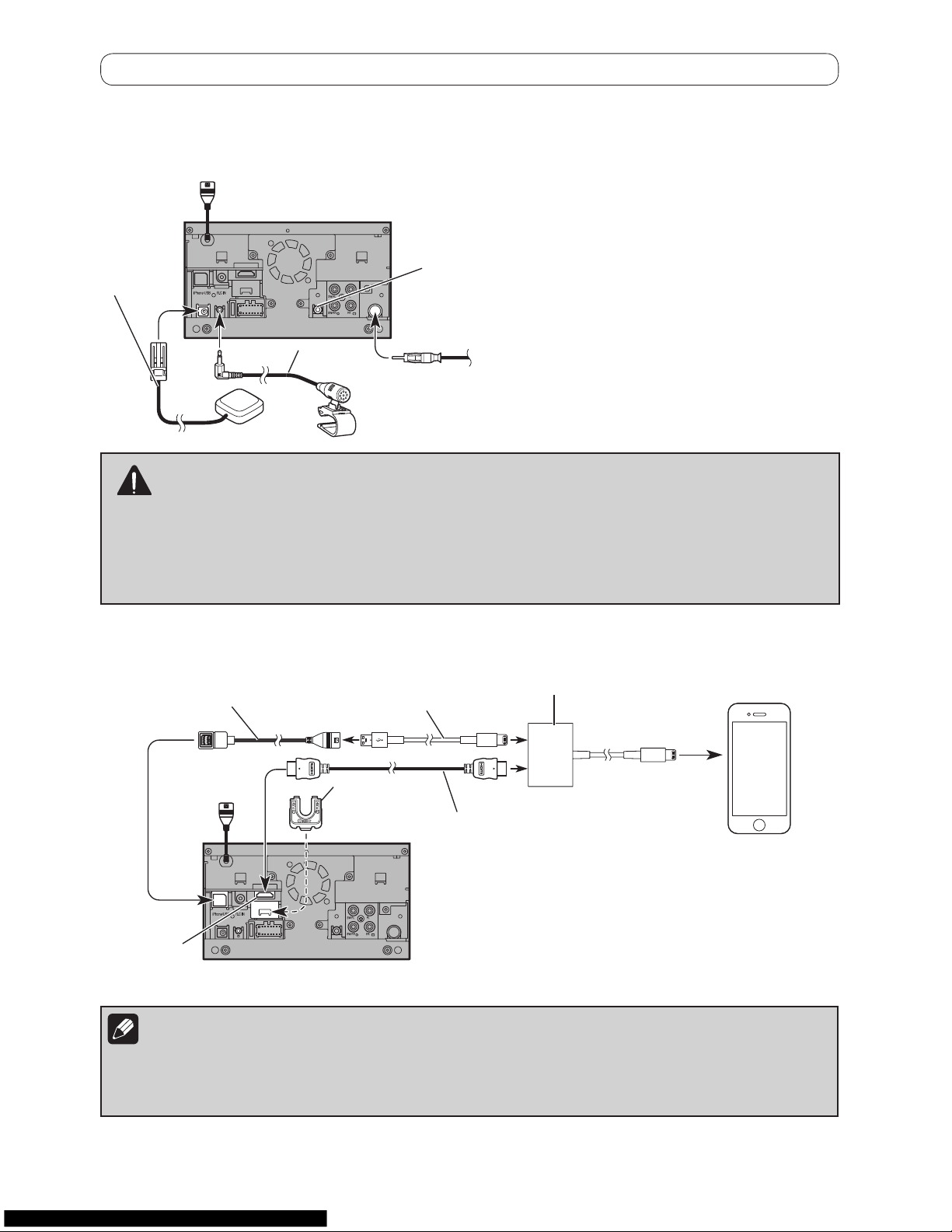
Connecting the system
Microphone
GPS antenna
Vehicle antenna
Wired remote input
Please refer to the instruction
manual for the Hard-wired remote
control adapter (sold separately).
4 m
(13 ft. 1 in.)
W
ARNING
• T
o avoid the risk of accident and the potential violation of applicable laws, this product should
never be used while the vehicle is being driven except for navigation purposes.
• In some countries, the viewing of images on a display inside a vehicle even by persons other than
the driver may be illegal. Where such regulations apply they must be obeyed and this product’s
app-based content should not be used.
When connecting an iPhone with Lightning connector
HDMI cable
holder
HDMI port
Notes
• When you connect the High Speed HDMI® Cable, use the HDMI cable holder to fix it securely
.
• The constant connection of the separately sold Lightning Digital AV Adapter (Apple Inc.
products) is not guaranteed. Disconnect it when it is not used as with a mobile device.
Lightning Digital AV Adapter
(Apple Inc. products) (sold separately)
High Speed HDMI
®
Cable (Type A-A)
(*2)
(sold separately) 2 m (6 f
t. 7 in.)
Lightning to USB Cable
(CD-IU52) (sold separately)
USB cable (*2) (sold separately)
1.5 m (4 f
t. 11 in.)
iPhone with Lightning
connector (*1)
(*1) For details concerning operations and compatibility, refer to
the Operation Manual.
(*2)
For details about how to connect the separately sold HDMI/
USB interface cable for iPod / iPhone (CD-IH202), refer to the
HDMI/USB interface cable for iPod / iPhone manual.
3.55 m
(1 f
t. 2 in.)
This product
Page 6
Connecting the system Connecting the system
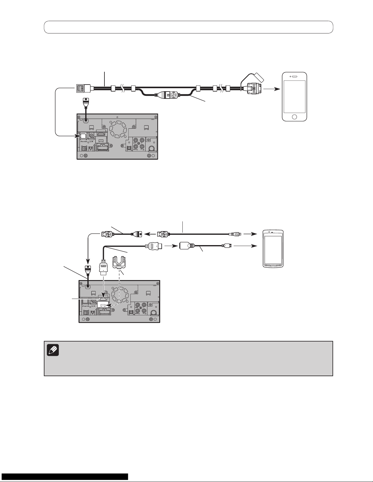
When connecting an iPhone with 30-pin
USB inter
face cable for iPod / iPhone (*4) (sold separately)
iPhone with 30-pin (*3)
2 m
(6 ft. 7 in.)
(*3) For details concerning operations and compatibility, refer to
the Operation Manual.
(*4)
For details about how to connect the separately sold USB
interface cable for iPod / iPhone (CD-IU201N), refer to the
USB interface cable for iPod / iPhone manual.
When connecting an Andr
oid device with an HDMI port
USB cable
HDMI port
(*5) For details concerning operations and compatibility,
refer to the Operation Manual.
(*6)
For details about how to connect the separately sold
App Connectivity Kit (CD-AH200), refer to the App
Connectivity Kit manual.
HDMI cable holder
Android device (*5)
Adapter cable (*6)
(HDMI Type A - D)
(sold separately)
High Speed HDMI
®
Cable (*6) (T
ype A - A)
(sold separately)
USB cable (*6) (Type USB A - USB A)
(sold separately) 0.75 m (2 ft. 6 in.)
USB - micro USB cable (*6) (Type USB A - micro USB B)
(sold separately) 1.5 m (4 ft. 11 in.)
Notes
• When you connect the High Speed HDMI® Cable, use the HDMI cable holder to fix it securely
.
• An MHL adapter will not be used if you use the adapter cable.
Page 7

When connecting an Andr
oid device with an MHL port
(*7) For details concerning operations and compatibility, refer
to the Operation Manual.
(*8)
For details about how to connect the separately sold App
Connectivity Kit (CD-AH200), refer to the App Connectivity
Kit manual.
Android device (*7)
MHL adapter (*8)
(sold separately)
High Speed HDMI
®
Cable (*8)
(T
ype A - A)(sold separately)
HDMI port
HDMI cable
holder
Notes
• When you connect the High Speed HDMI® Cable, use the HDMI cable holder to fix it securely
.
• An adapter cable will not be used if you use the MHL adapter.
USB cable (*8) (T
ype USB A - USB A)
(sold separately) 0.75 m (2 ft. 6 in.)
USB - micro USB cable (*8) (Type USB A - micro USB B)
(sold separately) 1.5 m (4 ft. 11 in.)
USB cable
When connecting a MirrorLink device with a USB port
MirrorLink device (*9)
USB cable
USB cable (*10) (Type USB A - USB A)
(sold separately) 0.75 m (2 ft. 6 in.)
USB - micro USB cable (*10) (Type USB A - micro USB B)
(sold separately) 1.5 m (4 ft. 11 in.)
(*9) For details concerning operations and compatibility, refer
to the Operation Manual.
(*10)
For details about how to connect the separately sold USB
interface cable for MirrorLink (CD-MU200), refer to the
USB interface cable for MirrorLink manual.
Page 8

Connecting the system Connecting the system
Connecting the power cor
d (1)
10
Y
ellow
To terminal supplied with power regardless
of ignition switch position.
Notes
• When a subwoofer is connected to this
product instead of a rear speaker
,
change the rear output setting in the
initial setting. (Refer to the Operation
Manual.)
• The subwoofer output of this product is
monaural.
F
use (10 A)
R
ed
To electric terminal controlled by ignition
switch (12 V DC) ON/OFF.
Orange/white
To lighting switch terminal.
Black (ground)
To vehicle (metal) body.
With a two-speaker system, do not connect
anything to the speaker leads that are not
connected to speakers.
Front speaker
White
White/black
Gray
Gray/black
Front speaker
Left
Rear speaker or
subwoofer (4 Ω)
Green
Green/black
Violet
Violet/black
Right
When using a subwoofer of 70 W (2 Ω), be sure to connect with the violet and violet/black leads of this
product. Do not connect anything with the green and green/black leads.
Not used.
Green
Green/black
Violet
Violet/black
Subwoofer (4 Ω) X 2
Rear speaker or
subwoofer (4 Ω)
Page 9

10
This product
F
use (10 A)
Power cord
Blue/white
To auto-antenna relay control terminal.
If the vehicle has a glass antenna, connect to the
antenna booster power control terminal (max. 300
mA 12 V DC).
Page 10

Connecting the system Connecting the system
Connecting the power cor
d (2)
Note
The position of the parking brake
switch varies depending on the
vehicle model. F
or details, consult
your authorized Pioneer dealer or
an installation professional.
V
iolet/white (REVERSE GEAR SIGNAL INPUT)
This is connected so that the this product can detect
whether the vehicle is moving forwards or backwards.
Connect the violet/white lead to the lead whose
voltage changes when the reverse gear is engaged.
Unless connected, the sensor may not detect your
vehicle traveling forward/backward properly, and thus
the position of your vehicle detected by the sensor
may be misaligned from the actual position.
W
ARNING
LIGHT GREEN LEAD A
T POWER CONNECTOR IS
DESIGNED TO DETECT PARKED STATUS AND
MUST BE CONNECTED TO THE POWER SUPPLY
SIDE OF THE PARKING BRAKE SWITCH.
IMPROPER CONNECTION OR USE OF THIS
LEAD MAY VIOLATE APPLICABLE LAW AND
MAY RESULT IN SERIOUS INJURY OR DAMAGE.
Note
When you use a rear view camera, please
make sure to connect this lead. Other
wise
you cannot switch to the rear view camera
picture.
P
ower cord
Power supply side
Ground side
Parking brake switch
Connection method
Clamp the lead of the power supply
side of the parking brake switch.
Clamp firmly with needle-nosed
pliers.
Light green (PARKING BRAKE)
Used to detect the ON/OFF status of the
parking brake. This lead must be connected
to the power supply side of the parking
brake switch.
If this connection is made incorrectly or
omitted, certain functions of this
product will be unusable.
This product
Page 11

When connecting to separately sold power amp/subwoofer
This product
F
ront outputs (FL, FR)
Subwoofer/rear outputs
(SW/RL, SW/RR)
Power cord
RCA cables
(sold separately)
Power amp
(sold separately)
Power amp
(sold separately)
System remote control
Left Right
Front speaker Front speaker
Subwoofer or
Rear speaker
Subwoofer or
Rear speaker
Blue/white
To system control terminal of the
power amp (max. 300 mA 12 V DC).
Note
Y
ou can change the RCA output of the subwoofer depending
on your subwoofer system. (Refer to the Operation Manual.)
Page 12

InstallationConnecting the system
When connecting a r
ear view
camera
When this product is used with a rear view
camera, it is possible to automatically switch
from the video to rear view image when the
shif
t lever is moved to REVERSE (R). Rear
View mode also allows you to check what is
behind you while driving.
W
ARNING
USE INP
UT ONLY FOR REVERSE OR
MIRROR IMAGE REAR VIEW CAMERA.
OTHER USE MAY RESULT IN INJURY
OR DAMAGE.
CA
UTION
• The screen image may appear reversed.
• The rear view camera is used as an aid to
keep an eye on trailers, or backing into a
tight parking spot. Do not use this function for entertainment purposes.
• Objects in rear view may appear closer or
more distant than in reality
.
• Please note that the image area shown
by the rear view camera may differ slightly when full-screen images are displayed
when backing and when checking the
rear of the vehicle while moving forward.
This product
R
ear view camera
(e.g. ND-BC6)
(sold separately)
For more details about the wiring, refer to
Connecting the power cord (2) on page 12.
Notes
• T
o display the rear view camera image, set
the rear view camera to on.
• Connect this product to the rear view camera only. Do not connect to any other
equipment.
P
ower cord
Violet/white
(REVERSE GEAR
SIGNAL INPUT)
Page 13

InstallationConnecting the system
Pr
ecautions before
installation
CA
UTION
• Never install this pr
oduct in places
where, or in a manner that:
– Could injure the driver or passengers
if the vehicle stops suddenly
.
– May interfere with the driver’s opera-
tion of the vehicle, such as on the
floor in front of the driver’s seat, or
close to the steering wheel or shift lever.
• Mak
e sure there is nothing behind the
dashboard or paneling when drilling
holes in them. Be careful not to damage fuel lines, brake lines, electronic
components, communication wires or
power cables.
• When using screws, do not allow them
to come into contact with any electrical
lead. Vibration may damage wires or
insulation, leading to a short circuit or
other damage to the vehicle.
• To ensure proper installation, be sure
to use the supplied parts in the manner
specified. If any parts are not supplied
with this product, use compatible parts
in the manner specified after you have
the parts’ compatibility checked by
your dealer. If parts other than supplied or compatible ones are used, they
may damage internal parts of this product or they may work loose and the
product may become detached.
• It is extremely dangerous to allow
cables to become wound around the
steering column or shift lever. Be sure
to install this product, its cables, and
wiring away in such so that they will
not obstruct or hinder driving.
• Make sure that leads cannot get caught
in a door or the sliding mechanism of a
seat, resulting in a short circuit.
• Please confirm the proper function of
your vehicle’s other equipment after
installation of this product.
• Do not install this product where it
may (i) obstruct the driver’s vision, (ii)
impair the performance of any of the
vehicle’s operating systems or safety
features, including airbags, hazard
lamp buttons or (iii) impair the driver’s
ability to safely operate the vehicle.
• Install this product between the driver’s seat and front passenger seat so
that it will not be hit by the driver or
passenger if the vehicle stops quickly.
• Never install this product in front of or
next to the place in the dashboard,
door, or pillar from which one of your
vehicle’s airbags would deploy. Please
refer to your vehicle’s owner’s manual
for reference to the deployment area of
the frontal airbags.
• F
ailure to follow all of these precautions may result in serious injury or
death.
T
o avoid electromagnetic
interference
In order to prevent inter
ference, set the following items as far as possible from this product,
other cables or leads:
• FM, AM antenna and its lead
• GPS antenna and its lead
In addition
, you should lay or route each antenna lead as far as possible from other antenna leads. Do not bind, lay or route them together, or cross them. Electromagnetic noise
will increase the potential for errors in the vehicle’s location display.
Befor
e installing
• Consult with your nearest dealer if installation requires drilling holes or other
modifications of the vehicle.
• Before making a final installation of this
product, temporarily connect the wiring
to confirm that the connections are correct and the system works properly
.
Page 14

Installation Installation
Installing this pr
oduct
Installation notes
• Do not install this product in places subject to high temperatures or humidity
, such
as:
– Places close to a heater, vent or air con-
ditioner.
– Places exposed to direct sunlight, such
as on top of the dashboard.
– Places that may be exposed to rain, such
as close to the door or on the vehicle’s
floor.
• Install this product in an area strong
enough to bear its weight. Choose a position where this product can be firmly
installed, and install it securely
. If this
product is not securely installed, the current location of the vehicle cannot be displayed correctly.
• Install this product horizontally on a surface within 0 to 60 degrees tolerance. Improper installation of the unit with the
surface tilted more than these tolerances increases the potential for errors in
the vehicle’s location display, and might
otherwise cause reduced display performance.
60°
• When installing, to ensure proper heat
dispersal when using this unit, make
sure you leave ample space behind the
rear panel and wrap any loose cables so
they are not blocking the vents.
Leave ample
space
5 cm
5 cm
• Do not squeeze this product into the
holder
. It may damage the front panel.
Page 15

P
arts supplied
The display unit
Flush sur
face screw
(5 mm × 9 mm)
(6 pcs.)
Truss head screw
(5 mm × 8 mm)
(6 pcs.)
Installation using the scr
ew holes
on the side of this product
1 F
asten the unit to the factory radio-
mounting brack
et.
Position this product so that its screw holes
are aligned with the screw holes of the bracket, and tighten the screws at three or four locations on each side. Use either the truss
head screws (5 mm × 8 mm) or flush sur
face
screws (5 mm × 9 mm), depending on the
shape of the bracket’s screw holes.
If the tab inter
feres with installation,
you may bend it down out of the way.
Factory radio-mounting bracket
Truss head screw or
flush surface screw
Be sure to use the
screws supplied
with this product.
Dashboard or console
Page 16

Installation Installation
Installing the GPS antenna
CA
UTION
Do not cut the GPS antenna lead to
shorten it or use an extension to make
it longer. Altering the antenna cable
could result in a short circuit or malfunction and permanent damage to this
product.
Installation notes
• The antenna should be installed on a level sur
face where radio waves will be
blocked as little as possible. Radio waves
cannot be received by the antenna if reception from the satellite is blocked.
Dashboard R
ear shelf
• When installing the GPS antenna inside
the vehicle, be sure to use the metal
sheet provided with your system. If this is
not used, the reception sensitivity will be
poor
.
• Do not cut the accessory metal sheet.
This would reduce the sensitivity of the
GPS antenna.
• Take care not to pull the antenna lead
when removing the GPS antenna. The
magnet attached to the antenna is very
powerful, and the lead may become detached.
• Do not paint the GPS antenna, as this
may affect its performance.
P
arts supplied
GPS antenna Metal sheet
When installing the antenna inside the vehicle
(on the dashboar
W
ARNING
D
o not install the GPS antenna over any sensors or vents on the dashboard of the vehicle, as
doing so may interfere with the proper
mise the ability of the metal sheet under the GPS antenna to properly and securely affix to
Affix the metal sheet on the sur
dow
. Place the GPS antenna on the metal sheet. (The GPS antenna is fastened with its magnet.)
When attaching the metal sheet, do not cut
it into small pieces.
• Some vehicles use window glass that does
not allow signals from GPS satellites to pass
through. On such models, install the GPS
antenna on the outside of the vehicle.
Page 17

When installing the antenna inside the vehicle
(on the dashboar
d or rear shelf)
W
ARNING
D
o not install the GPS antenna over any sensors or vents on the dashboard of the vehicle, as
doing so may interfere with the proper functioning of such sensors or vents and may compromise the ability of the metal sheet under the GPS antenna to properly and securely affix to
the dashboard.
Affix the metal sheet on the sur
face as level as possible where the GPS antenna faces the win-
dow. Place the GPS antenna on the metal sheet. (The GPS antenna is fastened with its magnet.)
GPS antenna
Metal sheet
Peel off the protective
sheet on the rear.
Make sure the surface is free of
moisture, dust, grime, oil, etc.,
before affixing the metal sheet.
Clamps
Use separately sold clamps
to secure the lead where necessary
inside the vehicle.
Note
The metal sheet
contains a strong
adhesive which may
leave a mark on the
sur
face if it is removed.
Notes
• When attaching the metal sheet, do not cut
it into small pieces.
• Some vehicles use window glass that does
not allow signals from GPS satellites to pass
through. On such models, install the GPS
antenna on the outside of the vehicle.
Page 18

Installation Installation
Installing the micr
ophone
• Install the microphone in a place where
its direction and distance from the driver
make it easiest to pick up the driver
’s
voice.
• Be sure to turn off (ACC OFF) the product before connecting the microphone.
Parts supplied
Microphone
Double-sided tape
Mounting on the sun visor
1 F
it the microphone lead into the
gr
oove.
Groove
Microphone lead
2
A
ttach the microphone clip to the
sun visor
.
Microphone clip
Clamps
Use separately sold clamps to secure the
lead where necessary inside the vehicle.
Install the microphone on the sun visor when
it is in the up position
. It cannot recognize the
driver’s voice if the sun visor is in the down
position.
Page 19

Installation on the steering column
1 Detach the microphone base fr
om the
microphone clip by sliding the micr
ophone
base while pressing the tab.
Microphone
Microphone clip Microphone base
Tab
2 Mount the microphone on the steering
column.
Double-sided tape
Install the microphone on the
steering column
, keeping it
away from the steering wheel.
Clamps
Use separately sold
clamps to secure the
lead where necessary
inside the vehicle.
Adjusting the microphone angle
The microphone angle can be adjusted.
PIONEER AUDIO SYSTEMS
CAR STEREOS
 Loading...