

Pioneer SD-P4053 Owner’s Manual
,pJ.F.J]Ol-_ tE-F_R
:,,_ ._r_ _. .-,_._-,_...,.,
PROJECTION MONITOR RECEIVER
S©-P4053
Thank you for purchasing the PIONEER Projection Monitor Receiv-
er.
If you have not read the precautionary instructions enclosed with
these operating instructions, please do so before proceeding.
After learning how to operate the Projection Monitor be sure to keep
this manual handy for future reference.
While the official name of the product is the "PROJECTION MONI-
TOR RECEIVER", for the sake of brevity the text refers to it as the
"Projection Monitor" or 'simply' the "Monitor ".
Contents
3 IMPORTANTNOTICE/ IMPORTANT
4 PRELIMINARYINSTRUCTIONS
5 FEATURES
6 INSTALLATION
6 OPERATINGPRECAUTIONS
7 INSERTINGBATTERIESIN THEREMOTE
CONTROLUNIT
7 REMOTECONTROLOPERATIONRANGE
8 FRONTPANELFACILITIES
10 SYSTEMCONNECTIONDIAGRAM
12 ANTENNACONNECTIONS
12 SYSTEMREMOTECONTROLCONNECTIONS
13 SPEAKERS
14 REMOTECONTROLUNIT FACILITIES
24 HOWTO ALIGNCOLORCONVERGENCE
27 TV CHANNELSELECTION
30 MULTI-CHANNELTV SOUND(MTS)
31 HOWTO RELABELINPUT DISPLAYS
32 TUNERPRESET
33 USINGTHE STATIONLABEL FUNCTION
34 PICTUREAND SOUNDADJUSTMENT
35 AV MEMORY
36 DPO ADJUSTMENT
37 HOW TOTURNTHE SYSTEM MODEFUNC-
TIONON AND OFF
38 TROUBLESHOOTING
39 CARE OFYOURPROJECTIONMONITOR
39 BLOCKDIAGRAM
40 SPECIFICATIONS
] PORTA ]THOT]CE
IMPORTANT
WARNING:TO REDUCETHE RISKOF FIRE
ORELECTRICSHOCK,DONOTEXPOSETHIS
APPLIANCETOWETLOCATIONS,
The model number and the serial number of this Projection
Monitor are located on the rear panel.
Please write the serial number on the enclosed warranty
card and keep it in a safe place for future reference.
NOTE:
There are no user servieeab/e parts inside the Projection
Monitor.
CAUTION
The lightning flash with arrowhead, within
an equilateral triangle, is intended to aterl
the user to the presence of uninsutated
"dangerous voltage" withi[1 the product's
enclosure that may be of sufficient magni-
tude to constitute a risk of electric shock to
persons.
CAUTION:
TO PREVENTTHE RISK OF ELECTRICSHOCK,
DONOTREMOVECOVER(OR BACK). NOUSER-
SERVICEA8LEPARTS INSIOE. REFER SERVIC-
ING TOQUALIFIEDSERVICEPERSONNEL.
The exclamation point within an equilater-
al triangle is intended to ale,1 the user to
the presence of important operating and
maintenance (servicing) instructions in the
literature accompanying the appliance,
P ELIMINARYINSTRUCTIONS
WHERE TO PUT THE MONITOR
LIGHTING
Bright lights or direct sunlight will dull the picture. Position the monitor so that the
screen faces away from windows.
AIR CIRCULATION
Leave space for air to circulate behind the monitor. Keep it away from curtains
and other furnishings that could block ventilation.
HEAT DAMAGE
Damage may occur ifyou leavethe monitor in direct sunlight or near aheater.
OPTIMUM VIEWING DISTANCE
10 to23 feet isthe rangerecommendedfor viewingcomfort,
POWER SOURCE
This Projection Monitor operates on AC 120 V, standard household voltage.
NEVER CONNECT THE PROJECTION MONITOR TO OTHER THAN THE
SPECIFIED VOLTAGE, OR TO DIRECT CURRENT.
POWER OUTLET
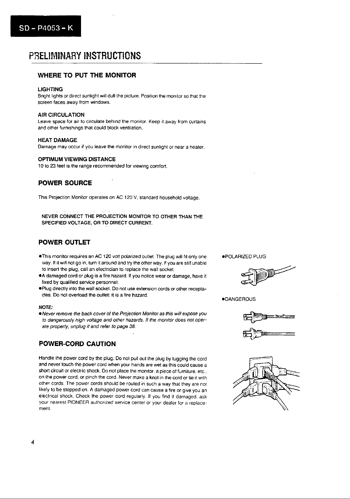
• This monitor requires an AC 120 volt polarized outlet. The plug will fit only one
way. If it will not go in, turn it around and try the other way If you are still unable
to insert the plug, call an electrician to replace the wall socket.
eA damaged cord or plug is a fire hazard. If you notice wear or damage, have it
fixed by qualified service personnel.
• Plug directly into the wall socket. Do not use extension cords or other recepta-
cles. DO not overload the outlet: it is a fire hazard.
NOTE:
• Never remove the back cover of the Projection Monitor as this will expose you
to dangerously high voltage and other hazards. /f the monitor does not oper-
ate properly, unplug it and refer to page 38.
POWER-CORD CAUTION
Handle the power cord by the plug. Do not pull out the plug by tugging the cord
and never touch the power cord when your hands are wet as this could cause a
short circuit or electric shock. Do not place the monitor, a piece of furniture, etc.,
on the power cord, or pinch the cord. Never make a knot in the cord or tie it with
other cords. The power cords should be routed in such a way that they are not
likely to be stepped on. A damaged power cord can cause a fire or give you an
electrical shock. Check the power cord regularly. If you find it damaged, ask
,/our nearest PIONEER authorized service center or your deater for a replace-
ment.
• POLARIZED PLUG
•DANGEROUS
FEATURES
Sharp, Clear Images with 730 line Horizontal Resolution (Video input)
eA !0 MHz video bandwidth and Dynamic Picture Control circuitry provide sharp detail and crisp outlines.
oN•w, high-resolution picture tubes improve focusing performance by 20%,
• Dynamic focusing c_rcuit enhances resolution at p_cture edges.
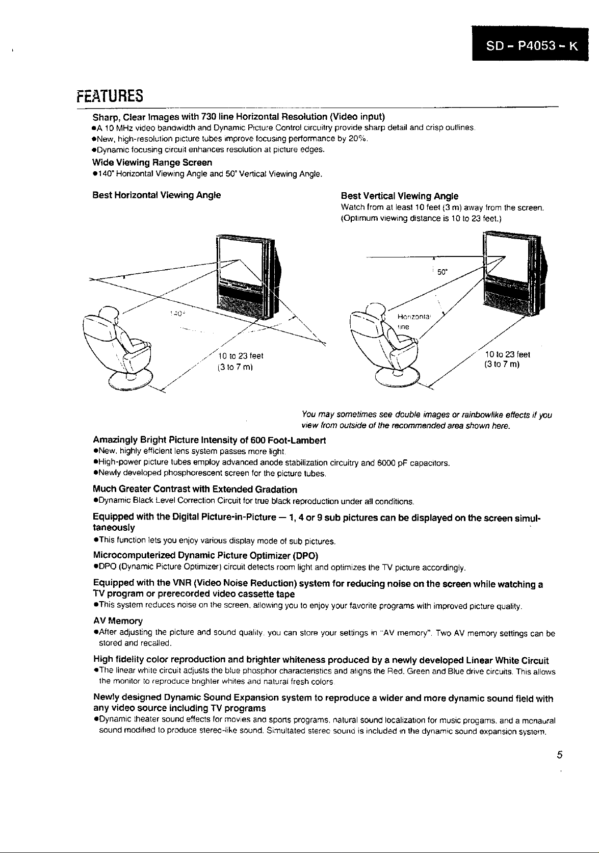
Wide Viewing Range Screen
• 140" Horizontal Viewing Angle and 50" Vertical Viewing Angle.
Best Horizontal Viewing Angle
\
Best Vertical Viewing Angle
Watch from at least 10 feet (3 m) away from the screen.
(Optimum viewing distance is 10 to23 feet.)
\
f
10 to 23 feet
(3to7m)
You may sometimes see double images or rainbow/ike effects ff you
view from euPside of the recommended area shown here.
Amazingly Bright Picture Intensity of 600 Foot-Lambert
• New. highly efficient lens system passes more light.
• High-power picture tubes employ advanced anode stabilization circuitry and 6000 pF capacitors.
• Newly de_/eloped phosphorescent screen for the picture tubes.
Much Greater Contrast with Extended Gradation
• Dynamic Black Level Correction Circuit for true black reproduction under all conditions.
Equipped with the Digital Picture-in-Picture -- 1, 4 or 9 sub pictures can be displayed on the screen simul-
taneously
• Thisfunction lets youenloyvariousdisplay mode of sub pictures.
Microcomputerized Dynamic Picture Optimizer (DPO)
• DPO (Dynamic PictureOptimizer) circuit detects room lightand optimizesthe TV picture accordingly.
Equipped with the VNR (Video Noise Reduction) system for reducing noise on the screen while watching a
TV program or prerecorded video cassette tape
• This system reduces noise on thescreen, a_!owingyou to enjoy your favorite programs with improved picture quality.
AV Memory
• After adjusting the picture and sound quality you can store your settings in 'AV memory". Two AV memory settings can be
stored and recalled.
High fidelity color reproduction and brighter whiteness produced by a newly developed Linear White Circuit
• The linear white circuit adjusts the blue phosphor characteristics and aligns the Red. Green and Blue drive circuits. This allows
the monitor to reproduce hr+ghter whites and natural fresh colors
Newly designed Dynamic Sound Expansion system to reproduce a wider and more dynamic sound field with
any video source including TV programs
• Dynamic theater sound effects for movies and sporls programs, natural sound localizationfor music progams, anda monaural
sound modified to produce stereo-like sound. Simu!tated stereo sound is included in the dynamic sound expansion system.
5
INSTALL ,Ti0H
ANTENNA CONNECTION
Connect to an outdoor antenna, cable box or centralized an-
tenna terminal (see page 12 for details)•
MOUNTING
The Projection Monitor isdesigned to be placed on the floor
or on a sturdy platform. The mounting surface should be flat
and steady.
INSTALLATION PRECAUTIONS:
Place of Installation
eWhen the Projection Monitor is operating, it is cooled by
air-flow through ventilation holes in the rear and bottom.
Therefore, avoid placing it in a location where the cooling
air-flow is hindered (e.g. against e waft).
eAvoid places subject to extremely high temperatures or
humidity, or to temperatures of 41 °F (5 *C) or lower. Also
avoid dusty places.
oDe not set the Projection Monitor in an unstable location
(such as on a shaky or tilted platform).
• When setting the Projection Monitor on a floormade of soft
material, make sure that the floor is not damaged by the
weight of the Projection Monitor.
elf the room temperature sudden/), rises (or if the Projection
Monitor is moved from a cool place to a hot place), con-
densation may form on the lenses, resulting in picture dis-
tortion or color fading. /f this occurs, simply wait a while
(with the POWER SW/TCH on) and the condensation will
disappear•
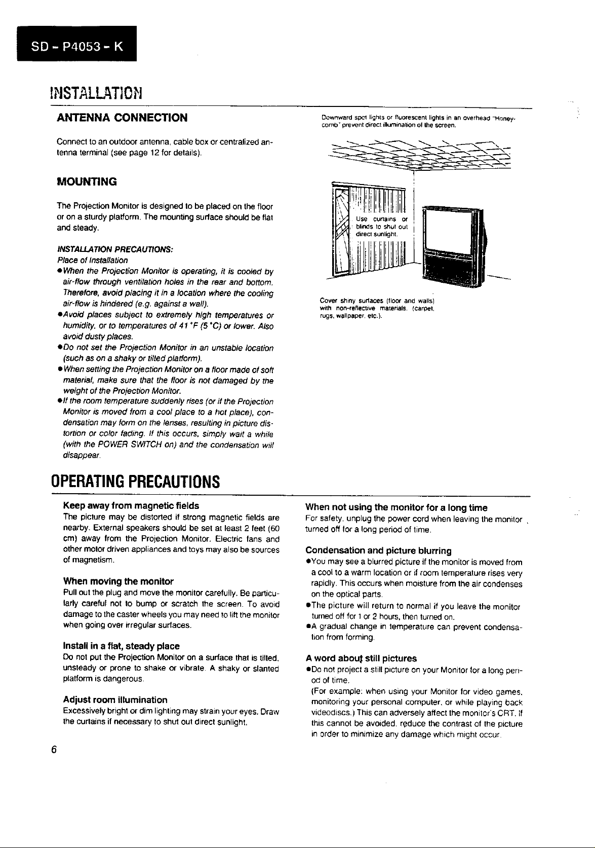
Downward si:_l lights or fluorescent lights in an overhead •Honey*
comb' prevent 0irect illumination of the screen¸
Cover shiny surfaces (floor and walls)
with non-reflective materials, tcamet,
rugs, wallpaper, etc.)
OPERATINGPRECAUTIONS
Keep away from magnetic fields
The picture may be distorted if strong magnetic fields are
nearby. External speakers should be set at least 2 feet (60
cm) away from the Projection Monitor. Electric fans and
other motor driven appliances and toys may also be sources
of magnetism.
When moving the monitor
Pull out the plug and move the monitor carefully. Be particu-
larly careful not to bump or scratch the screen. To avoid
damage to the caster wheels you may need to lib the monitor
when going over irregular surfaces.
Install in a flat, steady place
Do not put the Projection Monitor on a surface that is tilted,
unsteady or prone to shake or vibrate• A shaky or slanted
platform is dangerous•
Adjust room illumination
Excessively bright or dim lighting may strain your eyes. Draw
the curtains if necessary to shut out direct sunlight.
6
When not using the monitor for a long time
For safety, unplug the power cord when leaving the monitor ,
turned off for a long period of time.
Condensation and picture blurring
eYou may see a blurred picture if the monitor is moved from
a coot to a warm location or if room temperature rises very
rapidly. This occurs when moisture from the air condenses
on the optical parts.
eThe picture will return to normal if you leave the monitor
turnedoff for 1or 2 hours, then turned on.
eA gradual change in temperature can prevent condensa-
tion from forming,
A word abou_ still pictures
oDe not project a stiff picture on your Monitor for a long pen-
ed of time.
(For example: when using your Monitor for video games,
monitoring your personal computer, or while playing back
videodiscs.) This can adversely affect the monitor's CRT. if
this cannot be avoided, reduce the contrast of the picture
in order to minimize any damage which might occur
]NSERTiNGBATTERIESINTHERE 'tOTECONTROLUNIT
You wi!l find the remote control unit packed inside lhe projec-
tion monitor box Open the remote control unit _.nd _nsert the
batteries Fo!low the procedure below
] Open the battery compadmen_ on the rear of _he remote
control unt Press down wilh your thumb while sfid_ngthe
lid outward
[] Note the poiarity( + and - ) markings _nthe case Insert
the supplied batteries so that they match lhe markings
[] Close the lid by sliding it back tn until it clicks tnto p_ace
and press the RESET button with the til3of a ballpohntpen
The remote control unit _snow ready to use
Battery Replacement
If the TRANSMITILEARN indicator does not light when you
press a key. try pressing the RESET button and realtemutmg
your command. It the indicator still does not light the battebes
are low and should be replaced as soon as possible
Be sure to press the RESET button after the batteries are replac-
ed and the battery compartment cover is closed
(Even when the RESET button is pressed the programmed
s_gnals wi!l not be erased)
NO TE:
eThe remote control unit's power switch/s connected to the
battery compartment cover The un# wdlnot operate without
the cover even ff the batteries are loaded, and memory w_il
only be retazned for approximately 15minutes (even/f the bat-
ter/es are loaded)
Never close the cover when the battenes are not loaded The
programmed commands will be lost within a few seconds ff
you do so
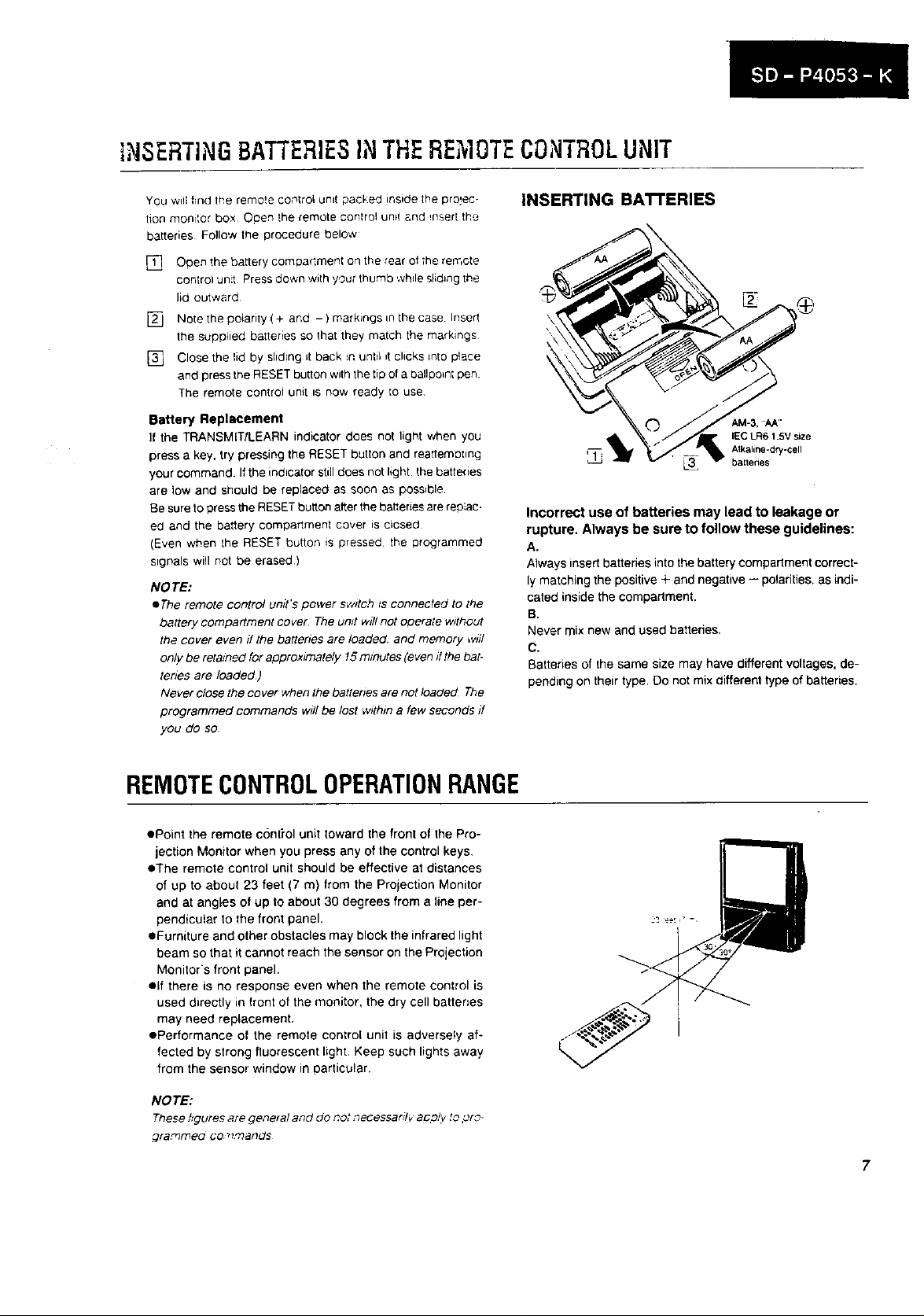
INSERTING BA'I-FERIES
-- Alkaline*dry-cell
q_l_ baltenes
Incorrect use of batteries may lead to leakage or
rupture. Always be sure to follow these guidelines:
A.
Always insert batteries into the battery compartment correct-
ly matching the positive + and negative -- polarities, as indi-
cated inside the compartment.
B.
Never mix new and used batteries.
C.
Batteries of the same size may have different voltages, de-
pending on their type. Do not mix different type of batteries.
IEC LR6 1.5V size
REMOTECONTROLOPERATIONRANGE
• Point the remote conti'ol unit toward the front of the Pro-
jection Monitor when you press any of the control keys.
eThe remote control unit should be effective at distances
of up to about 23 feet (7 m) from the Projection Monitor
and at angles of up to about 30 degrees from a line per-
pendicular to the front panel.
eFurniture and other obstacles may block the infrared light
beam so that it cannot reach the sensor on the Projection
Monitor's front panel.
elf there is no response even when the remote control is
used directly in front of the monitor, the dry cell batteries
may need replacement.
ePerformance of the remote control unit is adversely af-
fected by strong fluorescent light. Keep such lights away
from the sensor window in particular.
NO TE:
These hgures are ge,_eral and do riot _ecessardv aDo!y to pr?-
gra_meo Co _l.,'r?ands
7
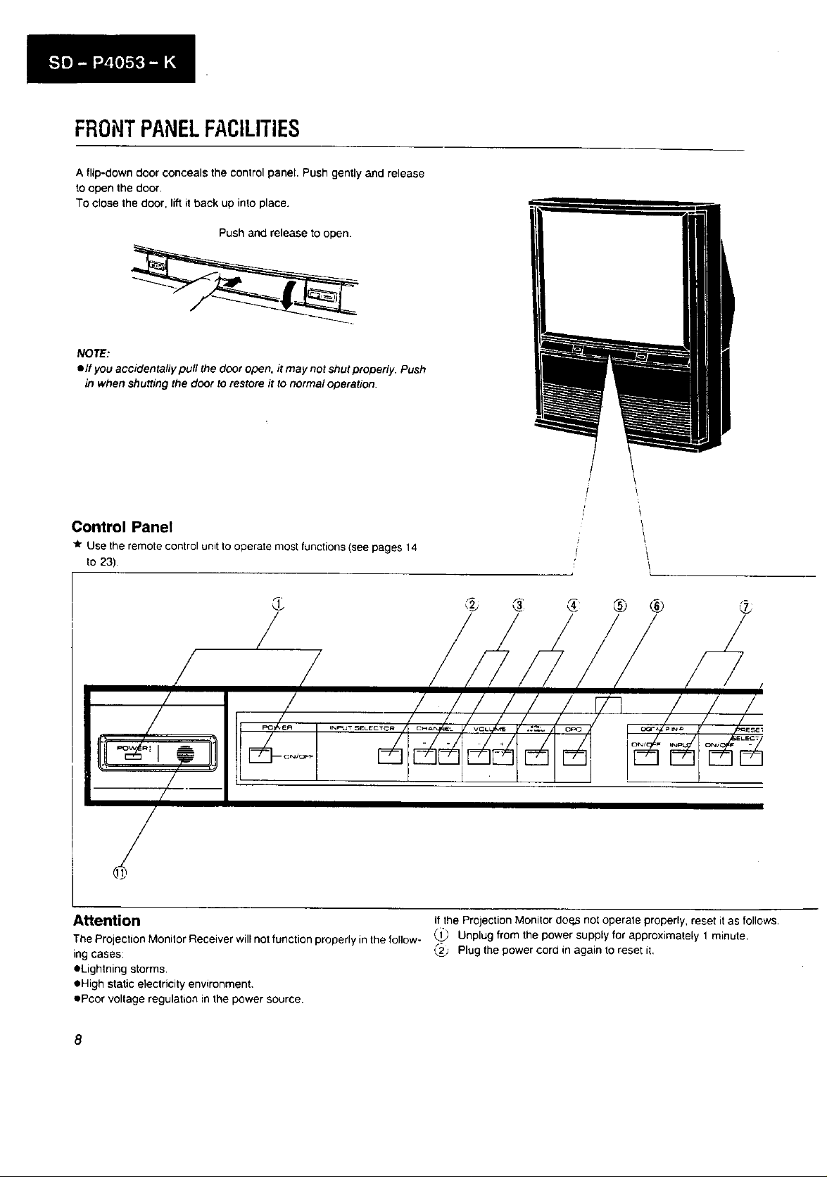
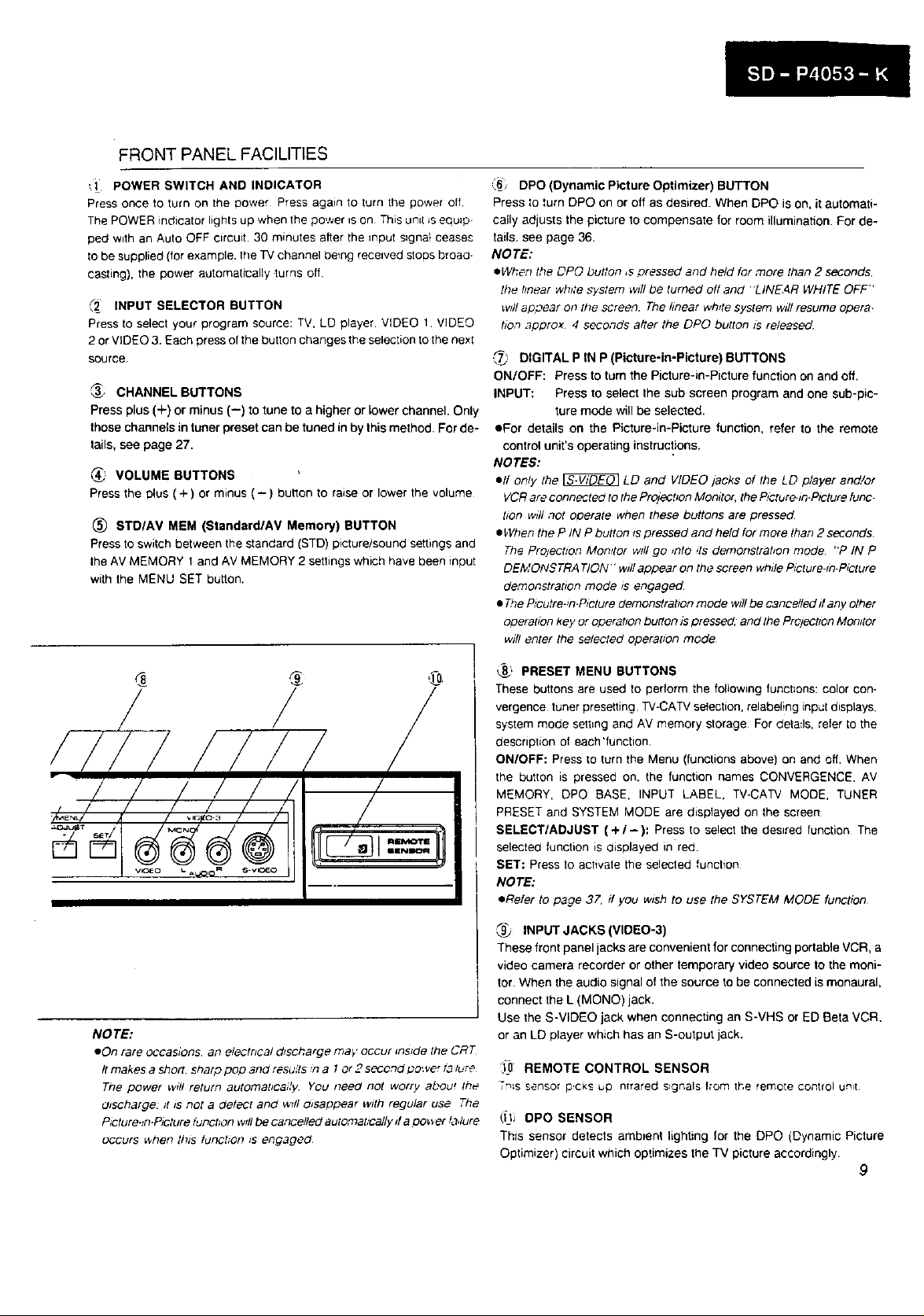
FRONTPANELFACILITIES
A flip-down door conceals the control panel. Push gently and release
to open the door.
TOclose the door, lift it back up into place.
Push and release to open.
NOTE:
• If you accidentally pull the door open, it may not shut properly. Push
in when shutting the door to restore it to normal operation.
Control Panel
_r Use the remote control unit to operate most functions (see pages 14
to 23)
'1
I
/
, , i i i
/I oolo/ / //// il
,_,=_-"SE_.EC_C. 0_'_'_'_ F "0'-_'._ _ 0':_7_
._======_.
(
®
Attention
The Projection Monitor Receiver will not function properly in the follow-
ing cases:
eLightning storms.
• High static electricity environment.
ePoor voltage regulation in the power source
® ®
I
/
i! ,I /
I _'"I"'_" 7' i_'_,_
if the Projection Monitor doe_ not operate properly, reset it as follows.
Unplug from the power supply for approximately 1 minute.
_j' Plug the power cord in again to reset it,
8
FRONT PANEL FACILITIES
([ POWER SWITCH AND INDICATOR
Press once to turn on the Dower Press again to turn the power off
The POWER indicator lights up when the power is on This unit Jsequip.
ped with an Auto OFF circuit. 30 minutes after the input s_gnat ceases
Io be supplied (for example, the TV channel betng received stops broad-
casting), the power automatically turns off
_2 INPUT SELECTOR BUTTON
Press to select your program source: TV, LD player. VIDEO 1 VIDEO
2 or VIDEO 3. Each press of the button changes the selection to the nexl
source.
_., CHANNEL BUTTONS
Press plus (+) or minus (--) to tune to a higher or lower channel. Only
those channels in tuner preset can be tuned in by this method. For de-
tails, see page 27.
_' VOLUME BUTTONS
Press the plus (+) or minus (-) buhon to raise or lower the volume
(_) STOIAV MEM (Standard/AV Memory) BUTTON
Press to switch between the standard (STD) picture/sound settings and
the AV MEMORY 1 and AV MEMORY 2 settings which have been input
with the MENU SET button.
,6 DPO(Dynamic Picture Optimizer) BUTTON
Press to turn DPO on or off as desired. When DPO is on, it automati-
cally adjusts the picture to compensate for room illumination. For de-
tails, see page 36.
NOTE:
eWhen the DPO button ,s pressed and held for more than 2 seconds.
the hnear white system will be turned off and 'LINE4R WHITE OFF"
w_llapoear on the screen. The linear white system will resume opera-
#on approx 4 seconds alter the DPO button _sreleased
.,_j DIGITAL P IN P (Picture-in-Picture) BUTTONS
ON/OFF: Press to turn the Picture-in-Picture function on and off.
INPUT: Press to select the sub screen program and one sub-pic-
ture mode will be selected.
eFor details on the Picture-in-Picture function, refer to the remote
control unit's operating instructions.
NOTES:
elf only the _ LD and VIDEO jacks of the LD player and/or
VCRare connected to the PrOlecbon Momtor, the P,cture-_n.PIctufefunc-
tion w_llnot operate when these buttons are pressed
• When the P IN P button _spressed and held for more than 2 seconds.
The Projection Monffor will go _nto ,ts demonstrabon mode "P IN P
DEMONSTRATION" wpJIappear on the screen while P_cture-_n-P_cture
demonstration mode _s engaged.
• 7_e P_cutre-n.P_cturedemonstratton mode will be cancelled ff any other
opera#on key or operatton butlon _Spressed, and the Prcjectzon Monitor
will enter the selected operatton mode
/
NOTE:
eOn rare occasions, an electrical d_scharge may occur _ns_de the CRT
It makes a short, sharp peg 3no results n a t or 2 s_ond power t_ lure
Tne power w_t! return automabcai/y You need not worry about the
U_scharge: /t is not a detect and wslJo_sappear with regular use The
P_cture._n.Picture tuPot/on will be cancelled automat,_ally ff a oo_er _a,lure
occurs _hen this tunct;on _s engaged
_." PRESET MENU BUTTONS
These buttons are used to perform the following functions: color con-
vergence tuner presetting TV-CATV selection, relabel!ng input displays.
system mode sett=ng and AV memory storage For details, refer to the
description of each'function.
ON/OFF: Press to turn the Menu (functions above) on and off. When
the button =s pressed on. the function names CONVERGENCE. AV
MEMORY, DPO BASE, INPUT LABEL, TV-CATV MODE, TUNER
PRESET and SYSTEM MODE are displayed on the screen
SELECT/ADJUST (+/-): Press to select the desired function The
selected function is displayed in red.
SET: Press to activate the selected function
NOTE:
• Refer to page 37. ff you w_sh to use the SYSTEM MODE function
,_ INPUT JACKS (VIDEO-3)
These front panel jacks are convenient for connecting portable VCR, a
video camera recorder or other temporary video source to the moni-
tor. When Ihe audio signal of the source to be connected is monaural,
connect the L (MONO) jack.
Use the S-VIDEO jack when connecting an S-VHS or ED Beta VCR.
or an LD player which has an S-output jack.
:_0 REMOTE CONTROL SENSOR
Tn_ssensor p:ckSup ntrared s_gnals Iror'n the remote control u_I
0J_ OPO SENSOR
This sensor detects ambient lighting for the DPO (Dynamic Picture
Optimizer) circuit which optimizes the TV picture accordingly.
9
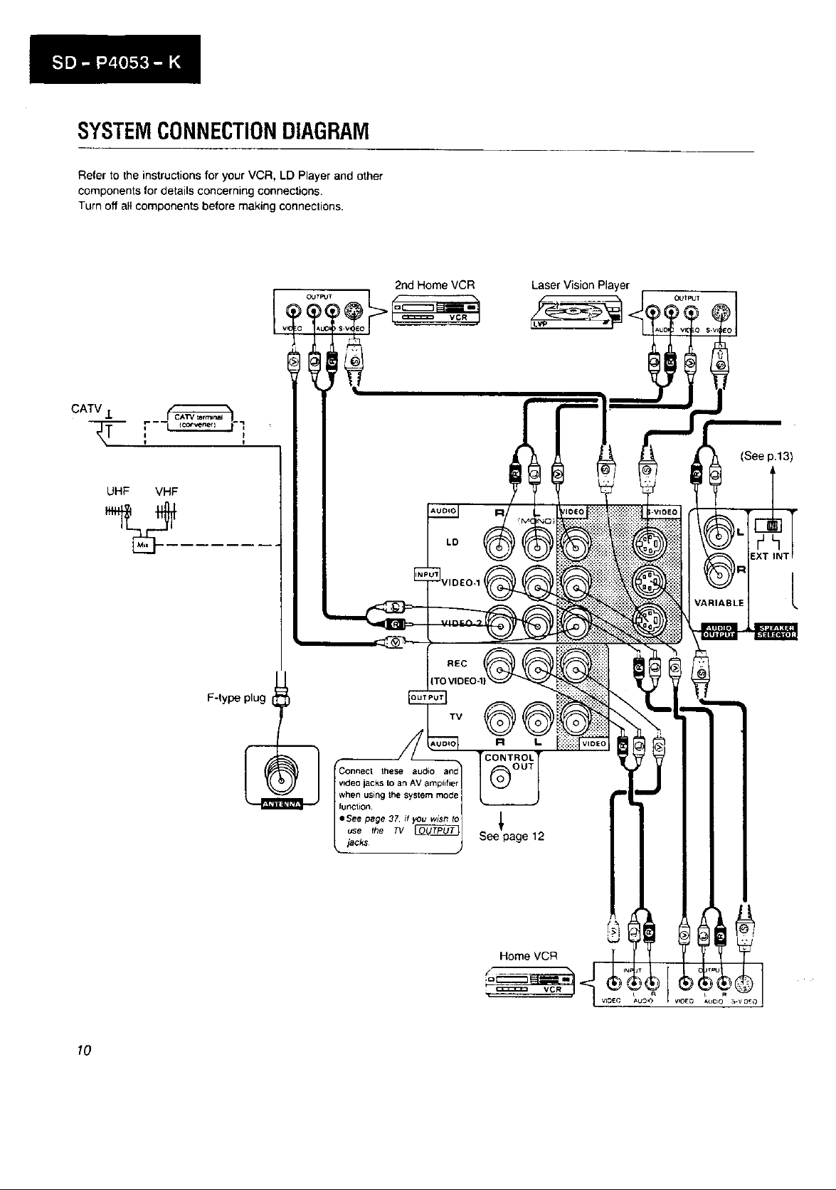
SYSTEMCONNECTIONDIAGRAM
Refer to the instructions for your VCR, LD Player and other
components for details concerning connections.
Turn off all components before making connections.
UHF VHF
Laser Vision Player
OUTPUT
(See p.13)
LD
BLE I L
F-type plug
TV
10
these audio
video jacks to an AV amplifier
when using the system mode
fur_tion
eSee page 37. if you wJsh to
use the 73/
iacks
See page 12
Home VCR
VCR
L
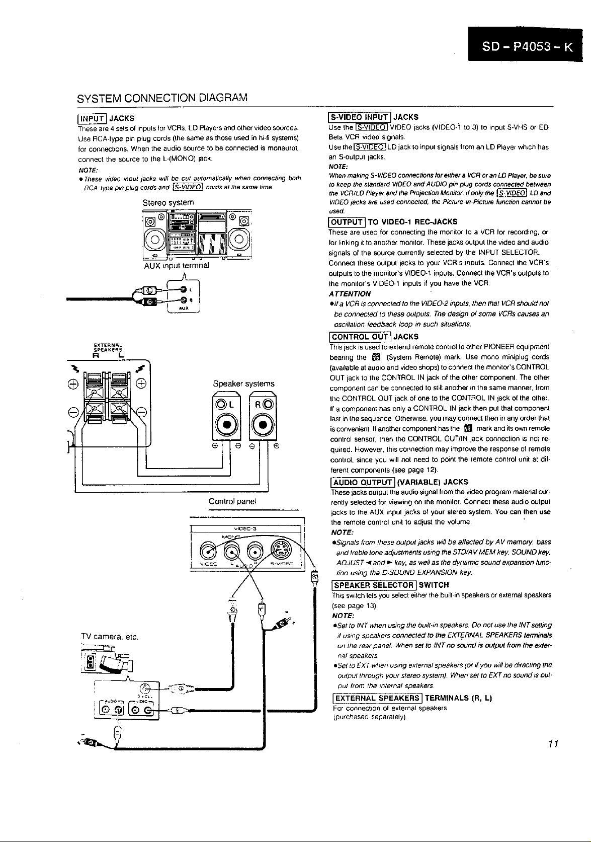
SYSTEM CONNECTION DIAGRAM
These are 4 sets ol inputs for VCRs+ LD Players and olher video sources
Use RCA-type pin plug cords (Ihe same as those used in hi-fi systems)
for connections When the audio source to be connected is monaural,
connecl the source to the L-(MONO) lack
®
JACKS
NOTE:
• These video input jacks will be cut automatically when connecting both
RCA type pin plug cords and _ cords at the same time.
Stereo system
AUX input lermnal
EXTERNAL
SPEAKERS
R L
Speaker systems
®
Control panel
I S-VIDEO INPUT I JACKS
Use Ihe _ VIDEO lacks (VIDEO-1 to 3) to inpui S-VHS or ED
Beta VCR video signals
Use Ihe _ LD jack Io input signals from an LD Player which has
an S-output lacks
NOTE:
When making S-VIDEO connectionsjot either a VCR or an LD Player. be sure
to keep the standard VIDEO and AUDIO pin plug cords connected between
the VCR/LD Player and the Projection Monitor. If only the _ LD and
VIDEO jacks are used connected, the Picture-in-Picture function cannot be
used.
TO VIDEO-1 REC-JACKS
These are used for connecting the monitor ioa VCR Ior recording, or
for linking it to another monitor. These jacks oulpul the video and audio
signals of the source currently selected by the INPUT SELECTOR.
Connect these oulpu/ jacks to your VCR's inputs. Connect Ihe VCR's
outputs to the monitor's VIDEO-1 inputs. Connect Ihe VCR's outputs to
Ihe monitor's VIDEO-1 inputs il you have the VCR
ATTENTION
ell a VCR _sconnected to the VIDEO-2 _nputs, then that VCR should no/
be connected to these outputs. The design el some VCRs causes an
osc#lahon feedback loop in such sguahons.
I CONTROL OUT I JACKS
This jack is used to extend remote control to other PIONEER equipment
bearing the _ (System Retool•) mark. Use mono minlplug cords
(available at audio and video shops) to connect the monilor's CONTROL
OUT jack to the CONTROL IN jack of the other componeht The other
component can be connected to still anoiher in the same manner, from
1he CONTROL OUT jack of one to the CONTROL IN lack of the other
If a component has only a CONTROL IN jack then put that pompon•hi
last in the sequence Otherwise, you may connect then in any order that
isconvenient If another component has lhe _ mark and itsown remc_e
control sensor, then the CONTROL OUT/IN jack connection is not re-
quired. However, this connection may improve the response of remote
control, since you will not need to point the remote control unit at dif*
ferent components (see page 12).
[AUDIO QUTPUT] (VARIABLE) JACKS
These jacks output the audio signal from the video program malerial cur-
rently selected for viewing on Ihe monitor Connecl these audio output
jacks to the AUX input jacks of your stereo system. You can Ihen use
the remote control unit to adjust the volume.
NOTE:
eStgnals from these output jacks wdl be affected by A V memory, bass
and treble lone adjustments ustng the STD/A V MEM key. SOUND key.
ADJUST _ and _" key, as well as the dynamic sound expansion func-
tion ustng the D-SOUND EXPANSION key.
[SPEAKER SELECTOR] SWITCH
This swilch lets you select either the built in speakers or exlemal speakers
(see page 13)
NOTE:
• Set to INT when ussng the budt.m speakers Do not use the/NTsetting
d using speakers connected to the EXTERNAL SPEAKERS terminals
on the tear panel When set to INT no sound is OUtpUt from the exter-
nal speakers
eSet to EX T when using external speakers (or if you willbe directing the
output Ihrough your slereo system) When set to EXT no sound zsout-
put from the internal speakers
I EXTERNAL SPEAKERS I TERMINALS (R, L)
For connection o[ exlemal speakers
(purchased separalely)
11
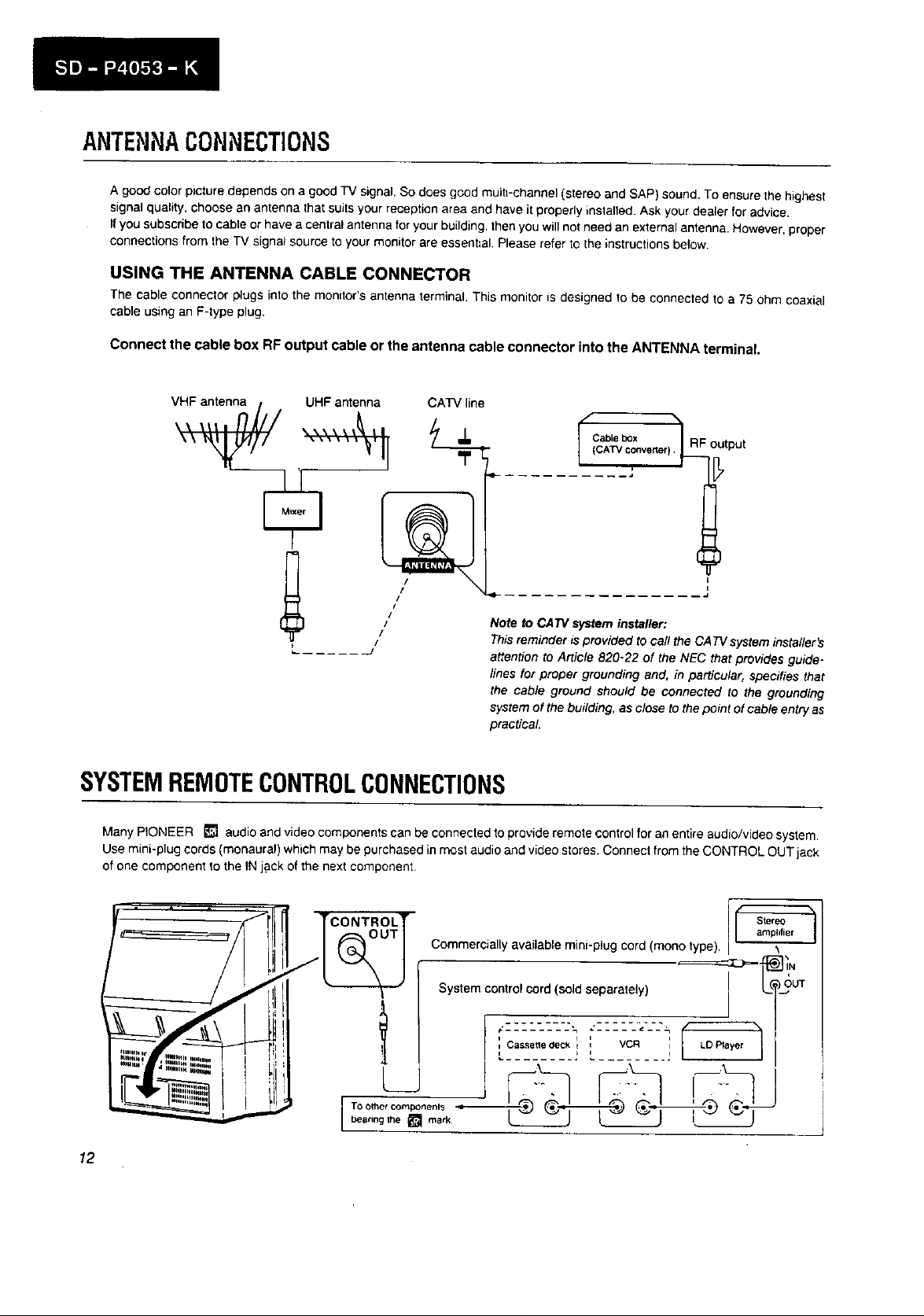
ANTENNACONNECTIONS
A good color picture depends on a good TV signal. So does good multi-channel (stereo and SAP) sound. To ensure the highest
signal quality, choose an antenna that suits your reception area and have it properly installed. Ask your dealer for advice,
Ifyou subscribe to cable or have a central antenna for your building, then you will not need an external antenna. However, proper
connections from the TV signat source to your monitor are essential. Please refer to the instructions below.
USING THE ANTENNA CABLE CONNECTOR
The cable connector plugs into the monitor's antenna terminal. This monitor is designed to be connected to a 75 ohm coaxial
cable using an F-type plug.
Connect the cable box RF output cable or the antenna cable connector into the ANTENNA terminal
UHF antenna CATV line
/
/
i1
/
/
/
/
J
........... J
Note to CA7V system installer:
This reminder is provided to call the CA 73/system insta//er's
attention to Article 820-22 of the NEC that provides guide-
Cable box 7 RF
I (CATV converter)_ output
lines for proper grounding and, in particular, specifies that
the cable ground should be connected to the grounding
system of the building, as close to the point of cable entry as
practical
SYSTEMREMOTECONTROLCONNECTIONS
Many PIONEER _ audio and video components can be connected to provide remote control for an entire audio/video system.
Use mini-plug cords (monaural) which may be purchased in most audio and video stores. Connect from the CONTROL OUT jack
cf one component to the IN jack of the next component,
12
= . _ .
/
TCONTROLT
I Stereoamplifier
Commercially available mini-plug cord (mono type).
System control cord (sold separately) _'T-'_=--1_ ]iN
_UT
I
t I i q
I Cassetle deck i i VCR i LO Prayer
SPEAKERS
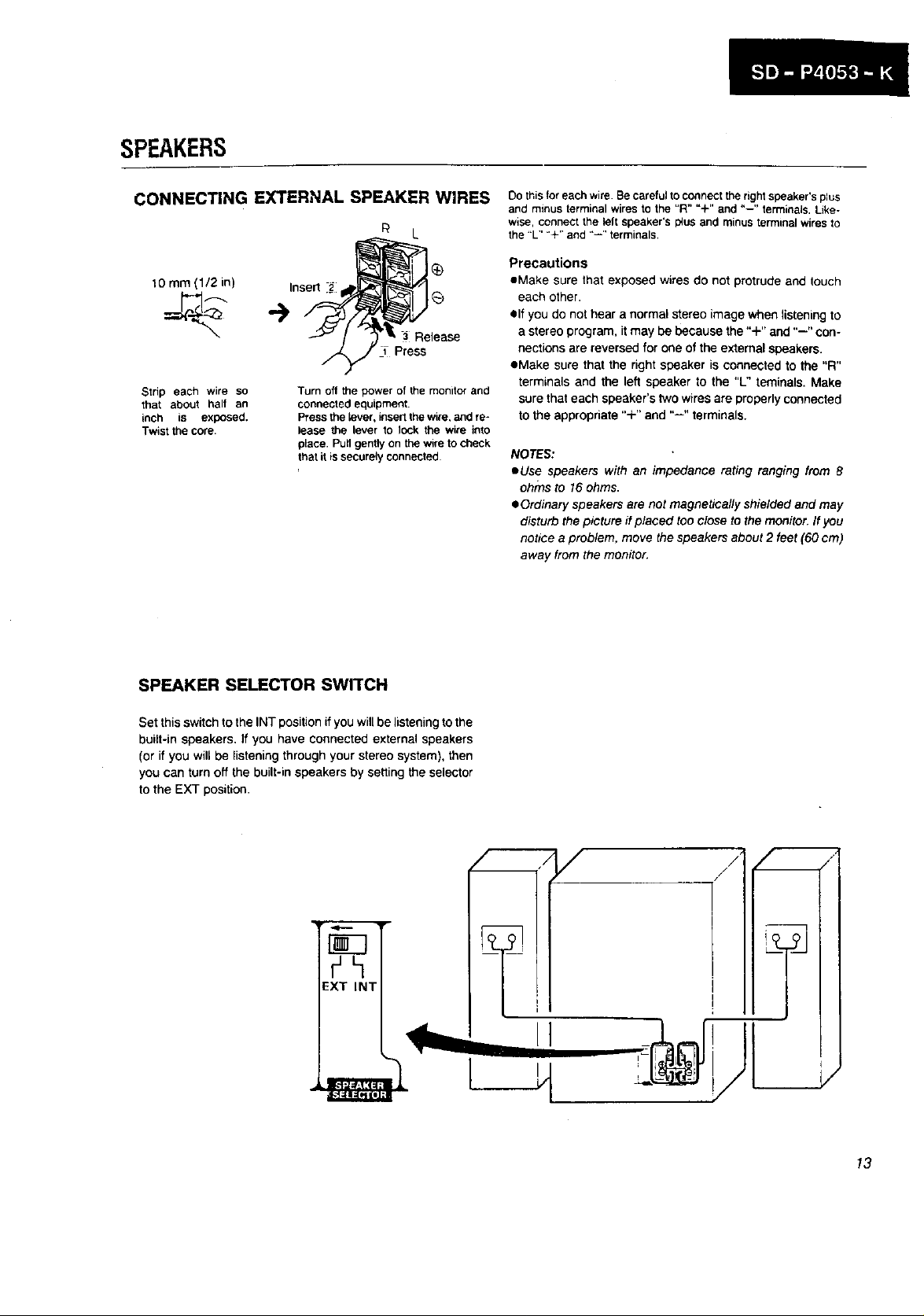
CONNECTING E_ERNAL SPEAKER WIRES
_L
10 mm (1/2 in) Insert ._
Release
Press
Strip each wire so
that about half an
inch is exposed.
Twist the core.
Turn off the power of the monitor and
connected equipment.
Press the {ever, insert the wire, and re*
{ease the lever to lock the wire into
place. Pull gently on the wire to check
that it is securely connected
Do this for each wire. Be careful to connect the right speaker's plus
and minus terminal wires to the "R" "+" and "--" terminals. Like-
w_se, connect the left speaker's I_US and minus terrninal wires to
the "L" "+" and "--" terminals.
Precautions
oMake sure that exposed wires do not protrude end touch
each other.
elf you do not hear a normal stereo image when listening to
a stereo program, it may be because the "+" and "--" con-
nections are reversed for one of the external speakers.
eMake sure that the right speaker is connected to the "R"
terminals and the left speaker to the "L" teminals. Make
sure that each speaker's two wires are properly connected
to the appropriate "+" and "--" terminals.
NOTES:
eUse speakers with an impedance rating ranging from 8
ohms to 16 ohms.
OOrdinary speakers are not magnetically shielded and may
disturb the picture ff placed too close to the monitor. If you
notice a problem, move the speakers about 2 feet (60 cm)
away from the monitor.
SPEAKER SELECTOR SWITCH
Set this switch to the INT position if you will be listening to the
built-in speakers, If you have connected external speakers
(or if you will be listening through your stereo system), then
you can turn off the built-in speakers by setting the selector
to the EXT position.
EXT INT
/
/
/ /
,/
j/
I_o_jj
I
J
13
 Loading...