

Pioneer SD-1100 Owners manual
PIONEEIII'
are
stereo
now the
display,
You
channel
is a multipurpose
measuring
your
individual
units are
tile
various
4-channel
components.
or 2-channel
a
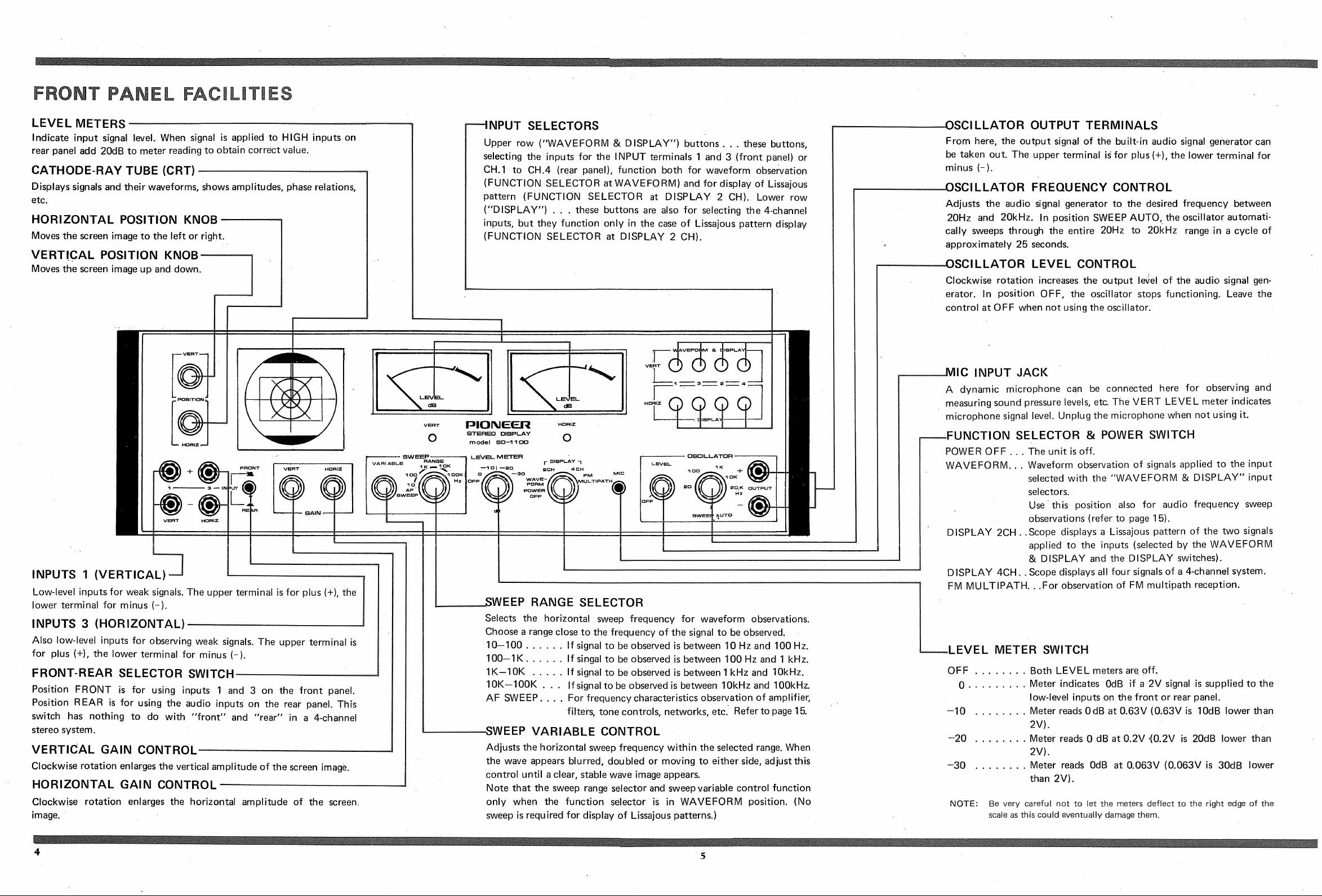
FEATURES
proud
owner of
model SD-1100.
instrument
performance
Incorporated
four-pole
Pioneer
a
observing
for
characteristics
stereo
system
in this
oscilloscope,
This
and
versa-
LEVEL
4-
unit
and
of
its
meters, an audio,signal
bility,
As
design
please
and
this
and operation
study the
fully and
a sweep
unit is rather
keep the manual
generator.
than
following
generator
with sweep
more complicated
other
audiocomponents,
instructions
hand for reference.
at
very care-
capa-
in its
4.CHANNEL
DISPLAY
ln addition
scope can
system
phase
DISTINCT,
SCOPE
The
even
the
on
For extra
tically dims the beam
prevent
OF
to normal
be used
simultaneously,
checks.
CLEARLY
IMAGE
quickly
screen
protection
burning
(3in.)
changing
makes
of the
75mm
of
2-channel
to show
all
permitting
READABLE
screen shows
signals,
various
adjustments
the screen, a
of
when only
phosphorescent
EASY.TO READ LEVEL
The large, clearly
permit
meter
scale
various input terminals
easy
range is adjustable
(+20d8)
BUILT-IN
For frequency
100
SD-1
freely adjustable
AUTO, the oscillator
whole
25 seconds.
contains
20Hz
readable
readout
to 20mV
AUDIO SIGNAL
response measurements
an audio signal
from 2OHz Lo 2OkHz. Set
to 20kHz
level meters
of various
in
(-40dB)
different sensitivity.
of
will automatically sweep
band
STEREO
stereo
four
signals
accurate
SIGNALS
signals,
of
balance
OSCILLO-
the
and
layer.
on the
def
practical
readings
from 20V
a clearly
and
special circuit
a spot is displayed,
METERS
level measurements.
10dB steps
in accordance
GENERATOR
to amplif iers
oscillator with
of approximately
cycle
in a
oscillo-
the
a 4-channel
and
image
ined
scale
easy.
automa-
panel
front
The
full
the
with
etc., the
frequencies
at SWEEP
over the
AUDIO
SWEEP
OBSERVATION
frequency
The
crossover
scope,
the
possible
zontal scope beam
by utilizing
VERSATILE,
High level
characteristics
networks,
peaks
and
EASILY
inputs accept comparatively
FACILITY FOR
FREOUENCY
OF
of
loudspeakers,
and
dips
the audio
deflection.
SWITCHABLE
DIRECT
RESPONSE
tone controls,
etc. can
can be
oscillator sweep
be
observed
detected.
INPUTS
strong signals
filters,
on
This
for hori-
(as
is
from amplifier's speaker outputs), while low level inputs
provided
are
to
(PRE-AMP
button
MULTIPLE
the built-in signal
With
overall
the
listening
and
adjusted
display
system
balancing
rate
record or test tape,
test
phono
of
1 100
SD
accurate
on the
out, etc.). lnputs are selected by simple
switches.
APPLICATIONS
frequency
room
accordingly
facility,
can be
cartridges and
provides
system
FM MULTIPATH
FM multipath
sound,
FM
free
multipath
special
a
positioned
input
output.)
for optimum
front
generator
characteristics
can be
for optimum sound.
phase
relations in a
observed
is
checks.
and, if necessary,
possible
with the LEVEL
frequency
tape
multitude
a
DETECTION
reception, the
detected,
can be
provided.
(The
Thus, the
and rear
measured and tone controls
equipment can be checked the
greatest
tuner
reception.
for
and a
your
of
2-channel or 4-channel
other characteristics
and
uses
of
POSSIBLE
enemy
thanks
must be
antenna can
level
low
good
stereo
With the Lissajous
corrected.
meters.
for
signals
microphone,
system
With
scientif
of distortion-
the special
to
equipped
precisely
be
push-
etc.
Accu-
a
ically
FM
with
WHERE
the SD-1100
As
transistors
poses
tion.
o
Direct sunlight
(except
great problems in regard
no
However,
TO
is
avoid
and
PLACE
equipped
fully
in the
the
cathode-ray
following
the vicinity
THE
with
tube),
heat dissipa-
to
kinds of
of heat
SD.llOO
silicon
it
places:
sources'
o
On
especially
o
Moist
o
The
formers,
near a
or
and
vicinity
on a
dusty
etc.
power
vacuum
places.
strong
of
amplifier
tube
magnets,
or transformet,
type amplifier.
motors,
and
trans-
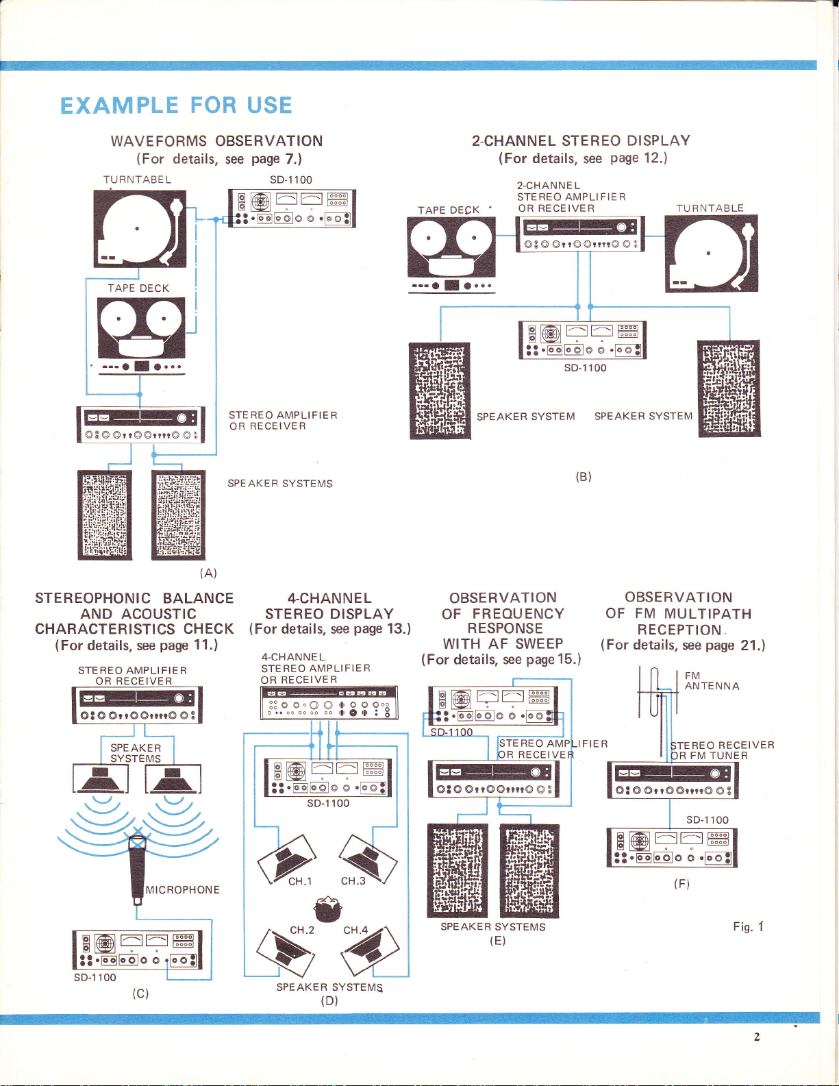
EXAMPLE
FOR
USE
WAVEFORMS OBSERVATION
(For
details, see
TURNTABE L
a
@3@@rt@@nr@@3
page
STEREO AMPLI FIER
RECEIVER
OR
SPEAKER
7.)
100
sD-1
SYSTEMS
TAPE DECK
.-.
O
O...
I
2.CHANNEL STEREO
(For
2-CHANNE L
STEREO AMPLIFIER
OR RECEIVER
EETI^E
E-l--fl
@8 @ @r
SPEAKER
details.
r@
sD-1 100
SYSTEM
ssg
@rrrr@ @
SPEAKER
(B)
page
DISPLAY
12.)
TU
3
SYSTEM
R NTAB LE
STEREOPHONIC
BALANCE
AND ACOUSTIC
CHARACTERISTICS
(For
details, see
STEREO AMPLI
OR RECEIVER
EET-E
ts-
Ot@ @rr@@nr@
SPE AKER
page
FIER
B@
3t.@
(A)
CHECK
11.)
@3
4-CHANNEL
STEREO
(For
details, see
4-CHAN NE L
STEREO
OR
;-....."J.
AMPLI
RECEIVER
::oo.OO,l,ooo"
DISPLAY
page
FIER
n rlOlr
OBSERVATION
FREOUENCY
OF
13.)
RESPONSE
WITH AF SWEEP
(For
details, see
i
B@FEffi
page
RECEI VE
15.)
OBSERVATION
OF FM
MULTIPATH
RECEPTION
(For
details,
page
see
REO RECEIVER
FM TUNER
R
21.)
EEII;AE
Ot@@rr@@rrrr@OB
@t@@rr@@rn@@3
B@FEffi
-
SPEAKER SYSTEMS
(F)
Fis.
f
SPEAKER SYSTEMS
l
I
REAR
n
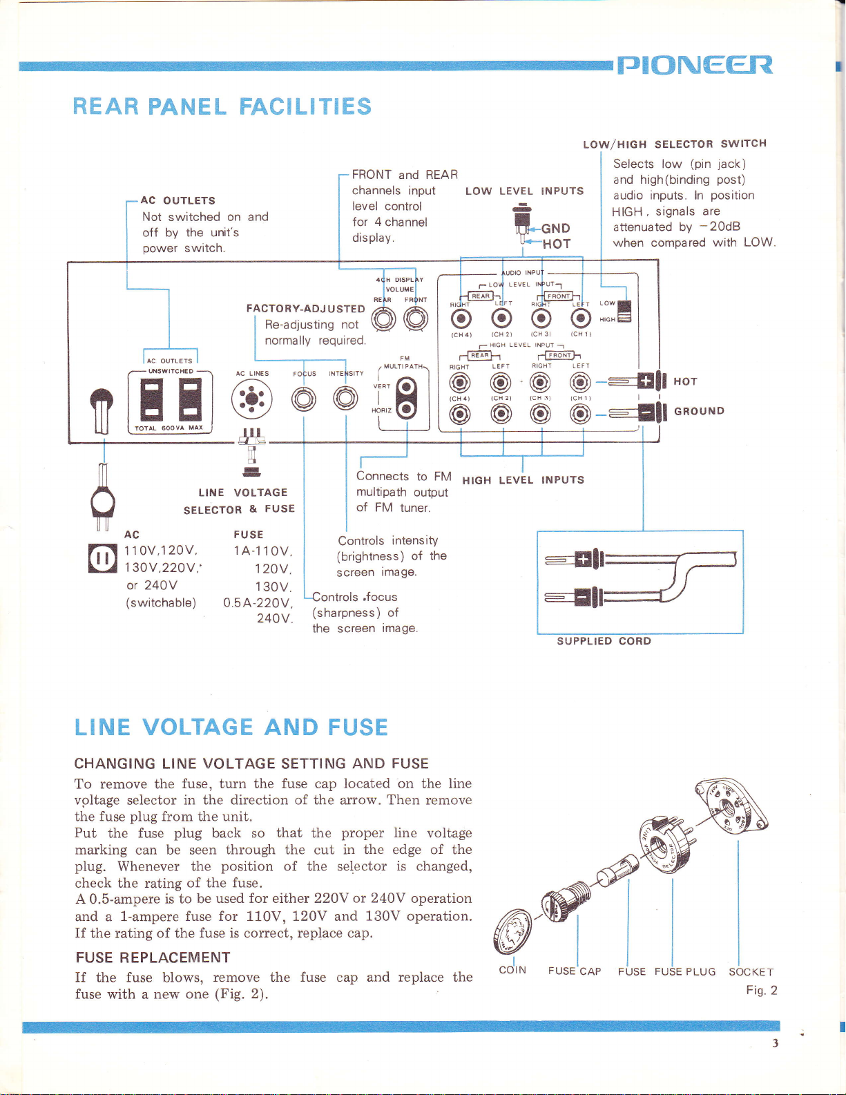
PANEL FACILITIES
AC
OUTLETS
Not switched on and
off by the unit's
power
WSWITCHED
switch.
FACTORY-ADJ
Re-adjusting not
normally required
USTED
'i=
E
SELECTOR
@
.
dlg_
il
fl
LINE VOLTAGE
-
FUSE
&
FRONT
channels input
level control
for
displav.
4
channel
and
i:Ei
Connects
multipath
of FM
to FM
output
tuner.
LOW/HIGH SELECTOR
REAR
LOW LEVEL INPUTS
-
ifn*o
Y*HOT
LEVEL
T
@@@@---Efl
HIGH
LEVEL
INPUTS
TJIONEER
SWlrcH
jack)
Selects low
and high(binding
audio inputs.
HIGH ,
attenuated by
when
(pin
post)
position
ln
signals
compared with
are
-20dB
u*ou*o
LOW.
t
AC FUSE
1 1 0V,1
1
or 240Y
(switchable)
LINE
CHANGING LINE VOLTAGE
To remove the
vpltage
the fuse
Put
marking
plug.
check the rating
A
and a 1-ampere
If the rating of the
FUSE REPLACEMENT
If
fuse
selector
the
Whenever the
0.5-ampere
fuse
the
with a
20V, 1A-1
30V,220V,'
1
120V,
130V.
0.5A-220V,
240V
VOLTAGE AND FUSE
fuse, turn the fuse cap located
in the direction of the arrow. Then remove
plug
from the unit.
plug
fuse
can be seen
is
blows,
new one
back so
through the cut in the edge of the
position
of the fuse.
be used
to
fuse for 1l-0V, 120V and
fuse is
for either 220Y
correct,
remove the
(Fig.
2).
0V,
SETTING
that
Controls
(brightness) of
screen
(sharpness)
the
screen
AND FUSE
proper
the
of the selector
or 240V
replace cap.
fuse
cap
intensitY
the
image.
of
image.
on
the line
line
voltage
is
changed,
operation
130V operation.
and replace the
@-ffi
FUSE
"ol,*
CAP FUSE
FUSE
PLUG
SOCKET
Fis.2
PI()NEEfiI
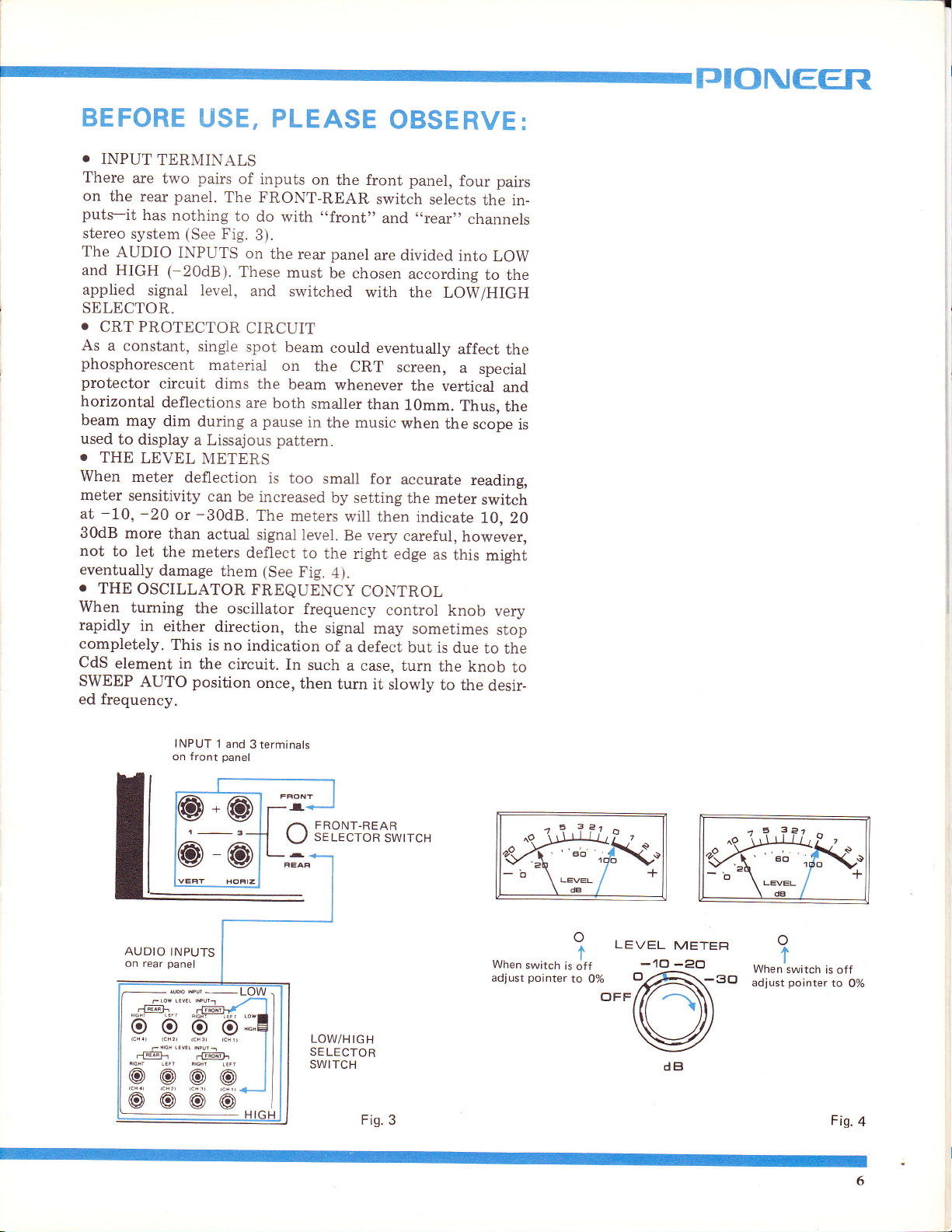
BEFORE
o
INPUT
There
on
the
puts-it
stereo
The
and HIGH
applied
SELECTOR.
o
CRT
As
a constant,
phosphorescent
protector
horizontal
beam
used
o
THE
When
meter
at
-10,
30dB more
not
eventually
.
THE
When
rapidly
completely.
CdS
SWEEP
ed frequency.
TERMINALS
are
two
panel.
rear
has
nothing
system
AUDIO
(See
INPUTS
(-20dB).
signal
PROTECTOR
circuit
deflections
may
dim
to display
LEVEL
meter
sensitivity
-20
deflection
or
than
to let
the meters
damage
OSCILLATOR
tuming
in either
This
element in
AUTO
USE, PLEASE
pairs
of
inputs
The FRONT-REAR
to
do
Fig.
3).
on
These
level,
singie
and
CIRCUIT
spot
material
dims
the
are
during
a Lissajous
METERS
can be
-30d8.
actual
pause
a
increased
The
signal
deflect
them (See
FREQUENCY
the
oscillator
direction,
is no
indication
the circuit.
position
once,
with
the
rear
must
switched
beam
on
beam
both
in
pattem.
is too
meters
level.
to
Fig.
frequency
the
In
such
then
on
the front
,,front,'
panel
be
chosen
could
the
CRT
whenever
smaller
the music
small
by
setting
will then
Be very
the right
4).
signal
of
a defect
a case, turn
turn
CONTROL
OBSERVE:
panel,
switch
and
are divided
according
with the
eventually
screen,
the
than
10mm.
when
for
accurate
the
careful,
edge
control
may sometimes
but is
it slowly
four pairs
selects
,,rear"
into
LOW/HIGH
affect
a
vertical
Thus,
the
meter
indicate
however,
as
this
knob
due
the knob
to the
the
in-
channels
LOW
to
the
the
special
and
the
scope
reading,
switch
10, 20
might
very
stop
to
the
to
desir_
is
INPUT
l
and
panel
NW--LUW
,t^;ay{ I
p
p::q
rtIqF I
AUDIO
on rear
-@-
I
rt$ilFr
on front
INPUTS
panel
I
@@@@
3terminals
^
I
I
I
FRONT-REAR
,/^'
se
\-)
LOW/H
SE LECTOR
SWITCH
le
croR
IGH
Fis.3
swtrcH
ro \rj!l-l: i
.ae
_.
When
switch
pointer
adjust
?.?Fr o
"eb
'
LryEL
\
dB
o
I
is off
to
--l\<--o
LEVEL
0%
OFF
r
a
+
-10
METEF|
-Po
o
no
"
irifl,,o
'60tY..!
LryEL
o
t
When
switch
pointer
adiust
,
is
to
Fis.
+
off
0%
4
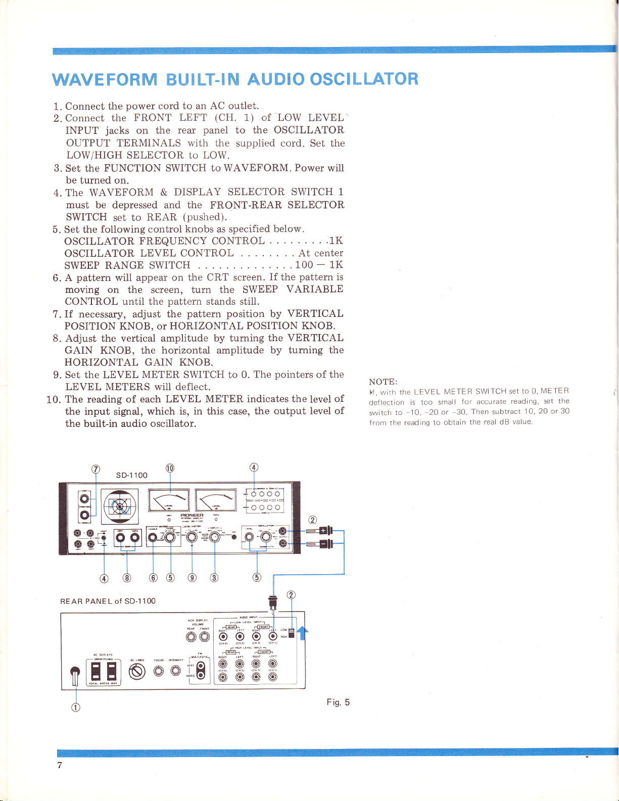
WAVE
FORM BUI LT-IN
AUDIO
OSCILLATOR
1. Connect
Connect
2.
INPUT
OUTPUT
LOW/HIGH
3.
Set the
be turned on.
4. The
WAVEFORM
must
SWITCH
5. Set the
power
the
the
jacks
cord to an
FRONT LEFT
rear
the
on
TERMINALS with the supplied cord.
SELECTOR to LOW.
FUNCTION SWITCH to
DISPLAY
&
be depressed and the
to REAR
set
following control
AC outlet.
(CH.
panel
FRONT-REAR
(pushed).
knobs
as specified
1)
to the OSCILLATOR
WAVEFORM.
SELECTOR SWITCH 1
oScTLLAToRFREQUENCYCONTROL
OSCILLATOR
SWEEP RANGE
pattern
A
6.
moving
CONTROL until
If
7.
POSITION
8.
Adjust the
on the screen, tum the SWEEP
necessary, adjust
GAIN KNOB, the
HORIZONTAL
9. Set the LEVEL
LEVEL
The
10.
the input sigrral, which
the built-in audio
METERS will deflect.
reading
LEVEL CONTROL
SWITCH
will appear
KNOB,
vertical amplitude by tuming
of each LEVEL
on the CRT screen.
pattern
the
the
HORIZONTAL POSITION KNOB.
or
horizontal
GAIN
METER SWITCH to 0.
oscillator.
stands stiil.
pattern
position
amplitude
KNOB.
METER indicates the
is, in this case,
The
the output level
of LOW
below.
LEVEL
Set
Power
SELECTOR
....1K
. . At center
....100-1K
pattem
If
the
VARIABLE
by VERTICAL
the VERTICAL
by turning the
pointers
of the
level
the
will
of
of
is
NOTE:
With thE
I.f
,
deflection
to
switch
the reading
from
LEVEL
is too
-1O,
METER
for
small
20 or 30-
obtain
to
TCH SEt
SWI
accurate
subtract
Then
the real dB
O,
TO
reading.
10, 20
value.
METER
the
set
or30
REAR PANEL of SD-1
lOO
TJTONEER
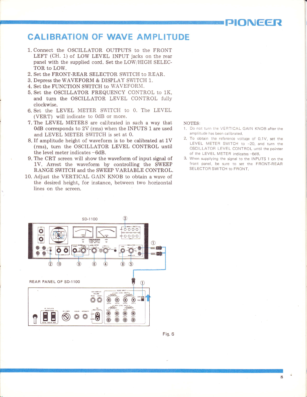
CALIBRATION
1. Connect
LEFT
panel
TOR
2.
Set
3. Depress
4.
Set the
5. Set
and turn the OSCILLATOR LEVEL CONTROL
clockwise.
Set the LEVEL
6.
(VERT)
7. The LEVEL
OdB
and LEVEL
If
8.
amplitude
(rms),
I
I
I
the
The
9.
1V. Arrest
RANGE
10. Adjust
the desired height, for instance,
lines
the OSCILLATOR
(CH.
1)
of LOW LEVEL
with the supplied cord.
to LOW.
FRONT-REAR
the
the WAVEFORM & DISPLAY SWITCH
FUNCTION
the OSCILLATOR
will indicate
METERS
corresponds to 2V
METER
height of waveform is
turn the OSCILLATOR LEVEL
meter indicates
level
CRT
screen
will show the waveform of input
the waveform by controlling the
SWITCH and the
the VERTICAL GAIN KNOB to
on
the screen.
OF WAVE AMPLITUDE
OUTPUTS
Set the
SELECTOR
SWITCH to
INPUT
SWITCH to REAR.
WAVEFORNI.
to
jacks
LOW/HIGH
FREQUENCY CONTROL to 1K,
METER SWITCH
OdB or more.
to
to 0. The LEVEL
are calibrated in such a way
(rms)
SWITCH
when the
is set at
INPUTS
0.
to be
calibrated
CONTROL
-6d8.
SWEEP
VARIABLE CONTROL.
obtain
between two
FRONT
the
on the rear
SELEC-
1.
1 are used
signal
SWEEP
a wave
horizontal
fully
that
at
until
1V
of
of
NOTES:
Do not
1.
2. To obtain
3.
turn the VERTICAL
amplitude
LEVEL METER
OSCILLATOR
Of
thE LEVEL
When
supplying
panei,
front
SELECTOR
has
been calibrated.
the reference voltaqe
SWITCH
LEVEL
METER
the
be sure to
SWITCH to FRONT.
ro
CONTROL unril
iNd|CAIES 6dB.
ro
signal
set the FRONT-REAR
GAIN KNOB
of 0.1V,
and turn the
-2O,
the INPUTS
after the
the
1 on the
the
set
pointer
tg@mgn*H#
Q:
@L
REAR PANEL
E
OF
SD.1
O
1OO
d
@@
d,.El
Fis.6
8
 Loading...