

Pioneer SC-1223-S User Manual

Operating Instructions
AV Receiver
SC- 12 23-K/-S
Operating Environment
CAUTION
TO PREVENT THE RISK OF ELECTRIC SHOCK, DO NOT
REMOVE COVER (OR BACK). NO USER-SERVICEABLE
PARTS INSIDE. REFER SERVICING TO QUALIFIED
SERVICE PERSONNEL.
D3-4-2-1-1_B1_En
WARNING
This equipment is not waterproof. To prevent a fire or
shock hazard, do not place any container filled with
liquid near this equipment (such as a vase or flower
pot) or expose it to dripping, splashing, rain or
moisture.
D3-4-2-1-3_A1_En
WARNING
To prevent a fire hazard, do not place any naked flame
sources (such as a lighted candle) on the equipment.
D3-4-2-1-7a_A1_En
VENTILATION CAUTION
When installing this unit, make sure to leave space
around the unit for ventilation to improve heat radiation
(at least 20 cm at top, 10 cm at rear, and 20 cm at each
side).
WARNING
Slots and openings in the cabinet are provided for
ventilation to ensure reliable operation of the product,
and to protect it from overheating. To prevent fire
hazard, the openings should never be blocked or
covered with items (such as newspapers, table-cloths,
curtains) or by operating the equipment on thick carpet
or a bed.
D3-4-2-1-7b*_A1_En
Operating environment temperature and humidity:
+5 °C to +35 °C (+41 °F to +95 °F); less than 85 %RH
(cooling vents not blocked)
Do not install this unit in a poorly ventilated area, or in
locations exposed to high humidity or direct sunlight (or
strong artificial light)
D3-4-2-1-7c*_A1_En
CAUTION
The STANDBY/ON switch on this unit will not
completely shut off all power from the AC outlet.
Since the power cord serves as the main disconnect
device for the unit, you will need to unplug it from the
AC outlet to shut down all power. Therefore, make
sure the unit has been installed so that the power
cord can be easily unplugged from the AC outlet in
case of an accident. To avoid fire hazard, the power
cord should also be unplugged from the AC outlet
when left unused for a long period of time (for
example, when on vacation).
D3-4-2-2-2a*_A1_En
This product is for general household purposes. Any
failure due to use for other than household purposes
(such as long-term use for business purposes in a
restaurant or use in a car or ship) and which requires
repair will be charged for even during the warranty
period.
K041_A1_En
WARNING
Store small parts out of the reach of children and
infants. If accidentally swallowed, contact a doctor
immediately.
D41-6-4_A1_En
Information for users on collection and disposal of old equipment and used batteries
Symbol for
equipment
Symbol examples
for batteries
Pb
These symbols on the products, packaging, and/or accompanying documents mean
that used electrical and electronic products and batteries should not be mixed with
general household waste.
For proper treatment, recovery and recycling of old products and used batteries,
please take them to applicable collection points in accordance with your national
legislation.
By disposing of these products and batteries correctly, you will help to save valuable
resources and prevent any potential negative effects on human health and the
environment which could otherwise arise from inappropriate waste handling.
For more information about collection and recycling of old products and batteries,
please contact your local municipality, your waste disposal service or the point of sale
where you purchased the items.
These symbols are only valid in the European Union.
For countries outside the European Union:
If you wish to discard these items, please contact your local authorities or dealer and
ask for the correct method of disposal.
K058a_A1_En
2

Thank you for buying this Pioneer product. Please read through these operating instructions so you will know how to operate your model properly.
Contents
01 Before you start
Checking what’s in the box ................................................................................................................................................ 7
Our philosophy .................................................................................................................................................................... 7
Features ............................................................................................................................................................................... 7
Installing the receiver ......................................................................................................................................................... 8
Loading the batteries .......................................................................................................................................................... 8
Operating range of remote control unit............................................................................................................................9
About using AVNavigator (included CD-ROM)................................................................................................................9
02 Controls and displays
Remote control .................................................................................................................................................................12
Display ...............................................................................................................................................................................14
Front panel ........................................................................................................................................................................15
03 Connecting your equipment
Connecting your equipment ............................................................................................................................................18
Rear panel .........................................................................................................................................................................18
Determining the speakers’ application ..........................................................................................................................19
Placing the speakers ........................................................................................................................................................20
Connecting the speakers .................................................................................................................................................21
Installing your speaker system ........................................................................................................................................21
Selecting the Speaker system .........................................................................................................................................23
About the audio connection ............................................................................................................................................23
About the video converter ................................................................................................................................................24
About HDMI ......................................................................................................................................................................24
Connecting your TV and playback components ............................................................................................................25
Connecting an HDD/DVD recorder, BD recorder and other video sources ...............................................................27
Connecting a satellite/cable receiver or other set-top box ...........................................................................................28
Connecting other audio components .............................................................................................................................29
Connecting additional amplifiers ....................................................................................................................................29
Connecting AM/FM antennas .........................................................................................................................................30
MULTI-ZONE setup ...........................................................................................................................................................31
Connecting to the network through LAN interface .......................................................................................................32
Connecting optional Bluetooth ADAPTER .....................................................................................................................33
Connecting an iPod ..........................................................................................................................................................33
Connecting a USB device ................................................................................................................................................34
Connecting an MHL-compatible device .........................................................................................................................34
Connecting an HDMI-equipped component to the front panel input .........................................................................34
Connecting to a wireless LAN .........................................................................................................................................34
Connecting an IR receiver ...............................................................................................................................................35
Plugging in the receiver ...................................................................................................................................................35
04 Basic Setup
Automatically conducting optimum sound tuning (Full Auto MCACC) .....................................................................37
The Input Setup menu ......................................................................................................................................................38
Operation Mode Setup .....................................................................................................................................................39
Changing the OSD display language (OSD Language) ................................................................................................40
About the Home Menu.....................................................................................................................................................40
05 Basic playback
Playing a source ...............................................................................................................................................................42
Playing an iPod .................................................................................................................................................................43
Playing a USB device .......................................................................................................................................................44
Playing an MHL-compatible device ................................................................................................................................45
Listening to the radio ........................................................................................................................................................46
Bluetooth ADAPTER for Wireless Enjoyment of Music ................................................................................................47
06 Listening to your system
Enjoying various types of playback using the listening modes ....................................................................................51
Selecting MCACC presets ...............................................................................................................................................53
Choosing the input signal ................................................................................................................................................53
Better sound using Phase Control ..................................................................................................................................53
07 Playback with NETWORK features
Introduction ....................................................................................................................................................................... 55
Playback with Network functions....................................................................................................................................56
About network playback...................................................................................................................................................58
About playable file formats ..............................................................................................................................................59
08 Control with HDMI function
About the Control with HDMI function ...........................................................................................................................61
Making Control with HDMI connections ........................................................................................................................61
HDMI Setup.......................................................................................................................................................................61
Before using synchronization ..........................................................................................................................................62
About synchronized operations ......................................................................................................................................62
Setting the PQLS function ...............................................................................................................................................62
About Sound Retriever Link and Stream Smoother Link ..............................................................................................62
Cautions on the Control with HDMI function ................................................................................................................63
09 Using other functions
Setting the Audio options ................................................................................................................................................65
Setting the Video options .................................................................................................................................................67
Switching the speaker terminals ....................................................................................................................................69
Using the MULTI-ZONE controls .....................................................................................................................................69
Network settings from a web browser ............................................................................................................................70
Using the sleep timer .......................................................................................................................................................70
Dimming the display ........................................................................................................................................................70
Switching the HDMI output .............................................................................................................................................70
Checking your system settings .......................................................................................................................................70
Resetting the system ........................................................................................................................................................71
3

10 Controlling the rest of your system
About the Remote Setup menu.......................................................................................................................................73
Operating multiple receivers ...........................................................................................................................................73
Setting the remote to control other components ..........................................................................................................73
Selecting preset codes directly .......................................................................................................................................73
Programming signals from other remote controls .......................................................................................................74
Erasing one of the remote control button settings ........................................................................................................74
Erasing all learnt settings that are in one input function .............................................................................................75
Direct function ..................................................................................................................................................................75
About the ALL ZONE STBY (All Zone Standby) and DISCRETE ON (Discrete On) functions ....................................75
Resetting the remote control settings ............................................................................................................................75
Controlling components ..................................................................................................................................................76
11 The Advanced MCACC menu
Making receiver settings from the Advanced MCACC menu ......................................................................................79
Automatic MCACC (Expert) .............................................................................................................................................79
Manual MCACC setup .....................................................................................................................................................80
Checking MCACC Data ....................................................................................................................................................83
Data Management............................................................................................................................................................83
12 The System Setup and Other Setup menus
Making receiver settings from the System Setup menu...............................................................................................86
Manual speaker setup ......................................................................................................................................................86
Network Setup menu .......................................................................................................................................................88
Checking the Network Information .................................................................................................................................89
MHL Setup ........................................................................................................................................................................89
The Other Setup menu .....................................................................................................................................................89
Making network settings using Safari ............................................................................................................................92
Using Safari to set a friendly name .................................................................................................................................92
Using Safari to update the firmware ...............................................................................................................................92
14 Additional information
Surround sound formats ...............................................................................................................................................104
About HDMI ....................................................................................................................................................................104
HTC Connect ...................................................................................................................................................................104
About iPod .......................................................................................................................................................................105
Windows 7 .......................................................................................................................................................................105
MHL..................................................................................................................................................................................105
Software license notice ..................................................................................................................................................105
Auto Surround, ALC and Stream Direct with different input signal formats ............................................................106
Speaker Setting Guide....................................................................................................................................................106
About messages displayed when using network functions .......................................................................................107
Important information regarding the HDMI connection ............................................................................................108
Cleaning the unit ............................................................................................................................................................108
Glossary ...........................................................................................................................................................................109
Features index .................................................................................................................................................................112
Specifications .................................................................................................................................................................113
Preset code list................................................................................................................................................................114
13 FAQ
Troubleshooting ................................................................................................................................................................95
Power .................................................................................................................................................................................95
No sound ...........................................................................................................................................................................95
Other audio problems ......................................................................................................................................................96
ADAPTER PORT terminal ................................................................................................................................................97
Video ..................................................................................................................................................................................97
Settings ..............................................................................................................................................................................97
Professional Calibration EQ graphical output ...............................................................................................................98
Display ...............................................................................................................................................................................98
Remote control .................................................................................................................................................................98
HDMI ..................................................................................................................................................................................99
MHL....................................................................................................................................................................................99
AVNavigator ......................................................................................................................................................................99
USB interface ..................................................................................................................................................................100
iPod ..................................................................................................................................................................................100
Network ...........................................................................................................................................................................101
Web Control ....................................................................................................................................................................102
Wireless LAN ...................................................................................................................................................................102
4

Flow of settings on the receiver
Flow for connecting and setting the receiver
The unit is a full-fledged AV receiver equipped with an abundance of functions and terminals. It can be used easily after following the procedure below to make the connections and settings.
Required setting item: 1, 2, 3, 4, 5, 7, 9
Setting to be made as necessary: 6, 8, 10, 11, 12
Important
The receiver’s initial settings can be made on the computer using Wiring Navi on the AVNavigator CD-ROM
included with the receiver. In this case, virtually the same connections and settings as in steps 2, 3, 4, 5, 6, 7
and 8 can be made interactively. For instructions on using AVNavigator, see About using AVNavigator (included
CD-ROM) on page 9.
1 Before you start
! Checking what’s in the box on page 7
! Loading the batteries on page 8
j
2 Determining the speakers’ application (page 19)
! 7.2 channel surround system (Front height)
! 7.2 channel surround system (Front wide)
! 7.2 channel surround system & Speaker B connection
! 5.2 channel surround system & Front Bi-amping connection (High quality surround)
! 5.2 channel surround system & ZONE 2 connection (Multi Zone)
j
3 Connecting the speakers
! Placing the speakers on page 20
! Connecting the speakers on page 21
! Installing your speaker system on page 21
! Bi-amping your speakers on page 22
j
4 Connecting the components
! About the audio connection on page 23
! About the video converter on page 24
! Connecting your TV and playback components on page 25
! Connecting AM/FM antennas on page 30
! Plugging in the receiver on page 35
j
5 Power On
j
6 Changing the OSD display language (OSD Language) (page 40)
j
7 MCACC speaker settings
! Automatically conducting optimum sound tuning (Full Auto MCACC) on page 37
j
8 The Input Setup menu (page 38)
(When using connections other than the recommended connections)
j
9 Basic playback (page 41)
j
10 Adjusting the sound and picture quality as desired
! Using the various listening modes (page 50)
! Better sound using Phase Control (page 53)
! Measuring the all EQ type (SYMMETRY/ALL CH ADJ/FRONT ALIGN) (page 79)
! Changing the channel level while listening (page 87)
! Switching on/off the Acoustic Calibration EQ, Auto Sound Retriever or Dialog Enhancement (page 65)
! Setting the PQLS function (page 62)
! Setting the Audio options (page 65)
! Setting the Video options (page 67)
j
11 Other optional adjustments and settings
! Control with HDMI function (page 60)
! The Advanced MCACC menu (page 78)
! The System Setup and Other Setup menus (page 85)
j
12 Making maximum use of the remote control
! Operating multiple receivers (page 73)
! Setting the remote to control other components (page 73)
5

Before you start
Checking what’s in the box ............................................................................................................7
Our philosophy ................................................................................................................................ 7
Features ............................................................................................................................................ 7
Installing the receiver ...................................................................................................................... 8
Loading the batteries ...................................................................................................................... 8
Operating range of remote control unit ........................................................................................ 9
About using AVNavigator (included CD-ROM) ............................................................................. 9
6

01
Before you start
Checking what’s in the box
Please check that you’ve received the following supplied accessories:
! Setup microphone (cable: 5 m)
! Remote control unit
! AAA size IEC R03 dry cell batteries (to confirm system operation) x2
! AM loop antenna
! FM wire antenna
! Power cord
! CD-ROM (AVNavigator)
! Quick start guide
! Safety Brochure
! Warranty sheet
Our philosophy
Pioneer is dedicated to making your home theater listening experience as close as possible to the vision of the
moviemakers and mastering engineer when they created the original soundtrack. We do this by focusing on three
important steps:
1 Designing with carefully selected components so as to transmit the original soundtrack
accurately
2 Allowing for customized acoustic calibration according to any listening area
3 Tuning that transmits soul
Features
% Class D Amplifier
This unit is an AV receiver developed based on the latest high performance Class D amplifier and integrating
the essence of Pioneer’s high sound quality designs. This new generation reference amplifier offers outstanding
performance with high sound quality and reproduces the latest in multi-channel digital contents.
% Auto Phase Control Plus
For discs created with standards other than Phase Control, the LFE channel is delayed upon recording in the first
place. This function automatically corrects for phase shifting on such discs and broadcast.
This function is particularly effective when playing multi-channel music containing low frequency effects (LFE).
% Hi-bit 24 Audio Processing
Creates a wider dynamic range with digital sources like CDs, DVDs or BDs. 16- and 20-bit PCM as well as compressed audio is requantized to 24 bits, more subtle musical expression.
% PQLS Bit-stream
Jitterless high quality playback is possible by connecting a PQLS-compatible player with HDMI connections.
This feature is only available when the connected Pioneer Blu-ray Disc Player supporting the PQLS function.
% dts Neo:X 7.1 compatible
This receiver supports the latest DTS processing format. The quality of Neo:X, originally designed for 9 channels
or more, can be enjoyed in a 7-channel environment.
% High Resolution Music Playback
High resolution music files with resolutions of 96 kHz/24 bit to 192 kHz/24 bit can be played. Playback of AIFF,
Apple Lossless, WAV and FLAC files via the front USB port and network is supported.
% DSD File Music Playback (via Front USB and HDMI)
Playback of high sound quality DSD music (DSD files and DSD discs (SACDs)) is supported.
% Gapless Playback
The silent section between tracks is skipped when playing music files, eliminating the interruptions that usually
occur when playing live or concert contents.
% Energy Saving Design
This AV receiver has an ecological design. In addition to even lower power consumption in standby, the receiver
is equipped with an “eco mode” for low power consumption when playing contents as well. Furthermore, the
eco mode can be easily set using dedicated buttons on the main unit and remote control as well as from the
application.
% iControlAV2013 Remote Application
This is an application for smartphones and tablets allowing intuitive operation of many of the AV receiver’s functions. Versions are available for iPhone, iPod touch, iPad and Android devices. The application can be downloaded free of charge from the App Store or Google Play.
% AVNavigator 2013
The CD-ROM (AVNavigator) included with this unit provides a variety of functions, such as Wiring Navi with a
guide for connecting the unit and setting up from the computer and an Interactive Manual for operating the
unit while reading the manual.
Also, Operation Guide describes the receiver’s playback operations and how to use several functions through
videos and illustrations.
! The provided CD-ROM includes the Windows version of AVNavigator.
! The Mac OS version of AVNavigator can be downloaded from http://www.pioneer.eu.
! AVNavigator is available not only for Windows and Mac OS but also for iPad (downloadable free of charge). For
details, see http://pioneer.jp/product/soft/iapp_avnavi/en.html.
% Apple AirPlay
With AirPlay you can stream music from iTunes to the SC-1223 and play it through your home theater system.
You can even use the receiver to view metadata including song title, artist as well as album art on a connected
display. With Pioneer’s Air Play-compatible receivers, you can easily enjoy your iTunes music in any room in the
house.
% iPod Playback
Your iPod, iPhone or iPad can be connected to the receiver’s USB terminal and RCA video terminal to play the
music/video files on the iPod, iPhone or iPad.
Also, the iPod, iPhone or iPad is charged when it is connected to the receiver.
% Play ZONE
When playing music contents on smartphones or other terminals via the network, the zone in which the music is
to be played can be specified.
% Input Volume Absorber
Differences in the volume between inputs can be adjusted manually. If the volume seems different for certain
inputs, individual inputs can be adjusted to the user’s tastes by ±12 dB.
% HDMI (3D, Audio Return Channel)
8in/2out (As for 2out; You can select “Dual out” or “HDZONE out”)
A compatible component is required to use the above function.
% Ultra HD (with 4K video support) – Pass-through and upscaling –
4K resolution images can be passed through and displayed as such, and the Hi-Vision or Full Hi-Vision images
of DVDs, Blu-ray discs and HD broadcasts can be upscaled to a resolution of up to 4K and displayed. A separate
monitor supporting Ultra HD (4K video) is required.
®
7
01
Before you start
% HDZONE output
This receiver supports output of the HDMI output to a subzone room. Powerful images can be enjoyed simply by
connected this receiver to a TV supporting 4K/Full-HD/3D. In addition, a multi-channel environment can be created by connecting this receiver to another AV receiver in the subzone room.
% MHLTM (Mobile High-definition Link)-compatible device playback
An incorporates MHL 2 mobile device can be connected to enjoy 3D videos, Full-HD videos, high quality multichannel audio, and photos etc., with charge the battery on the receiver.
% HTC Connect
HTC Connect makes it easy to wirelessly stream your favorite music straight from your HTC phone. There’s no
need for a separate app; HTC Connect is built right into your phone’s music player.
% Dolby Pro Logic llz compatible
Adding a pair of speakers above the front left and right speakers adds expressiveness in the vertical direction to
the previous horizontally-oriented sound field. The height channel strengthens the sound field’s sense of threedimensionality and air, producing presence and expansion.
% Virtual Speakers
By turning on “Virtual Surround Back”, “Virtual Height”, and “Virtual Wide” modes realize a maximum of 11.2
channels combining the actually installed speakers and the virtual speakers is possible. This makes for smoother
connection between the sounds and an improved 3D feel.
% Auto Sound Retriever
The Auto Sound Retriever feature employs DSP technology to restore sound pressure and smooth jagged artifacts left over after compression.
% Sound Retriever Link
By connecting a Pioneer player supporting the Sound Retriever Link function, compressed audio files played on
the player can be corrected automatically to play the sound with higher density.
This feature is only available when the connected Pioneer Blu-ray Disc Player supporting the PQLS function.
% Stream Smoother Link
By connecting a Pioneer player supporting the Stream Smoother Link function, compressed video or movie files
played on the player can be corrected automatically to play them with a more natural, easily viewable picture.
This feature is only available when the connected Pioneer Blu-ray Disc Player supporting the PQLS function.
% Internet Radio
By connecting this receiver to the network via the LAN terminal, you can listen to Internet radio stations.
% Bluetooth compatible
Using the Bluetooth ADAPTER (AS-BT100 or AS-BT200) lets you enjoy music files on an iPhone or other Bluetooth
wireless technology device wirelessly.
% Wireless LAN Converter Ready
With the AS-WL300 wireless LAN converter (Optional), you can enjoy wireless LAN connection for the AV receivers. The AS-WL300 works with power supply from the AV receiver’s dedicated USB terminal, so no AC adapter is
required.
% Easy setup using Advanced MCACC
The Auto MCACC Setup provides a quick but accurate surround sound setup, which includes the advanced features of Professional Acoustic Calibration EQ.
Installing the receiver
! When installing this unit, make sure to put it on a level and stable surface.
! Don’t install it on the following places:
— on a color TV (the screen may distort)
— near a cassette deck (or close to a device that gives off a magnetic field). This may interfere with the sound.
— in direct sunlight
— in damp or wet areas
— in extremely hot or cold areas
— in places where there is vibration or other movement
— in places that are very dusty
— in places that have hot fumes or oils (such as a kitchen)
! Do not touch this receiver’s bottom panel while the power is on or just after it is turned off. The bottom panel
becomes hot when the power is on (or right after it is turned off) and could cause burns.
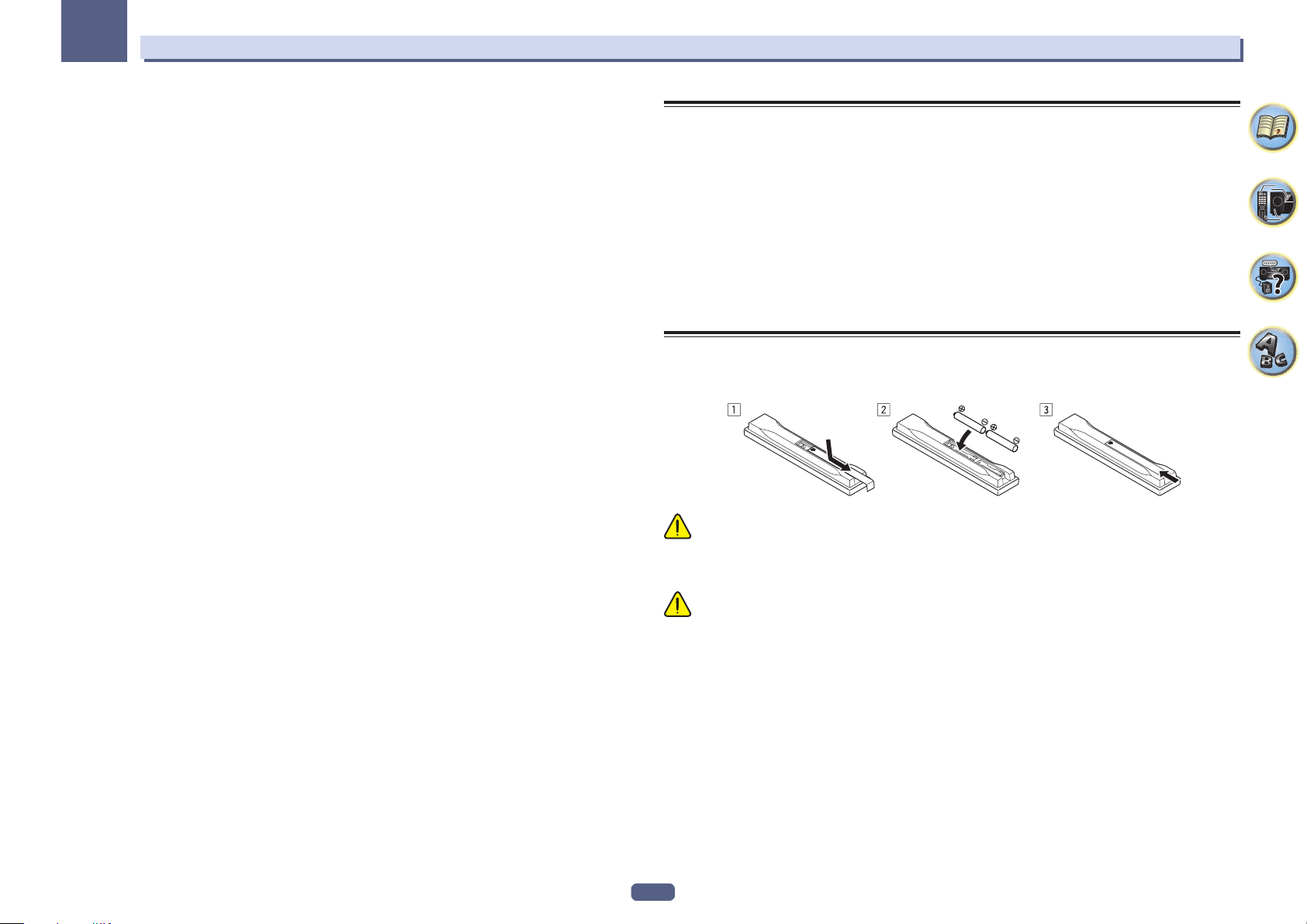
Loading the batteries
The batteries included with the unit are to check initial operations; they may not last over a long period. We recommend using alkaline batteries that have a longer life.
WARNING
! Do not use or store batteries in direct sunlight or other excessively hot place, such as inside a car or near a
heater. This can cause batteries to leak, overheat, explode or catch fire. It can also reduce the life or performance of batteries.
CAUTION
Incorrect use of batteries may result in such hazards as leakage and bursting. Observe the following precautions:
! Never use new and old batteries together.
! Insert the plus and minus sides of the batteries properly according to the marks in the battery case.
! When inserting the batteries, make sure not to damage the springs on the battery’s (–) terminals. This can
cause batteries to leak or overheat.
! Batteries with the same shape may have different voltages. Do not use different batteries together.
! When disposing of used batteries, please comply with governmental regulations or environmental public insti-
tution’s rules that apply in your country/area.
8
01
Before you start
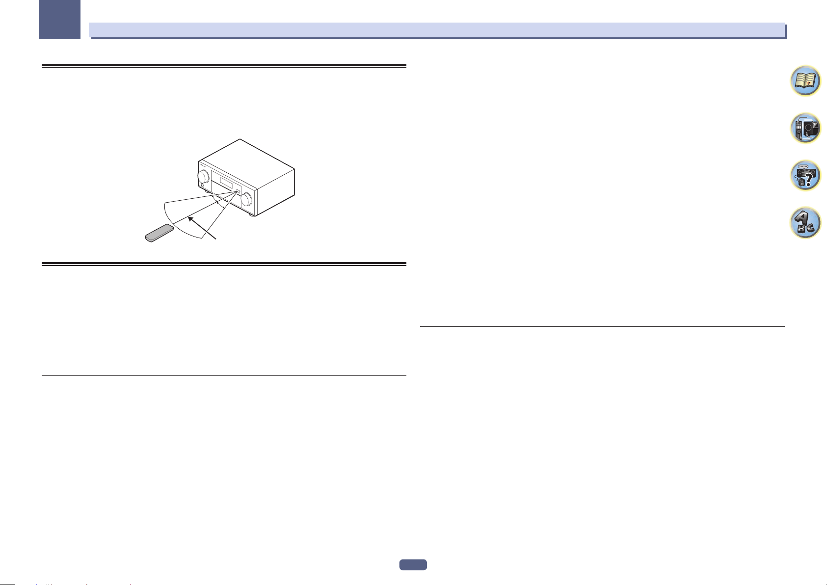
Operating range of remote control unit
The remote control may not work properly if:
! There are obstacles between the remote control and the receiver’s remote sensor.
! Direct sunlight or fluorescent light is shining onto the remote sensor.
! The receiver is located near a device that is emitting infrared rays.
! The receiver is operated simultaneously with another infrared remote control unit.
30°
30°
7 m
About using AVNavigator (included CD-ROM)
The included AVNavigator CD-ROM contains Wiring Navi allowing you to easily make the receiver’s connections
and initial settings in dialog fashion. High precision initial settings can be completed easily simply by following
the instructions on the screen to make the connections and settings.
There are also other features enabling easy use of various functions, including an Interactive Manual that operates in association with the receiver, updating of various types of software, and MCACC Application that lets you
check the MCACC measurement results on 3D graphs.
! The Mac OS version of AVNavigator can be downloaded from http://www.pioneer.eu.
! The iPad version of AVNavigator can be downloaded from the App Store.
! The provided CD-ROM includes the Windows version of AVNavigator.
Installing AVNavigator for Windows
1 Launch the desktop from the start screen (for Windows 8 only).
2 Load the included CD-ROM into your computer’s CD drive.
The CD-ROM’s top menu screen appears.
! A screen for selecting the CD-ROM’s operation (“Open with Explorer”, “Launch ‘MAIN_MENU.exe’”, etc.) may
be displayed. When the operation for launching “MAIN_MENU.exe” is performed, the AVNavigator menu
appears. A caution regarding security may appear during this operation, but there is no security problem, so
continue the operation.
! If the CD-ROM’s top menu screen is not displayed, double-click “MAIN_MENU.exe” on the CD-ROM. When
this is done, a caution regarding security is displayed, but there is no security problem, so continue the
operation.
3 Click “AVNavigator” on the “Installing Software” menu.
4 Follow the instructions on the screen to install.
When “Finish” is selected, installation is completed.
5 Remove the included CD-ROM from the computer’s CD drive.
Handling the CD-ROM
Operating Environment
! AVNavigator can be used with Microsoft® Windows® XP/Windows Vista®/Windows® 7/Windows® 8.
! A browser is at times used for AVNavigator functions. The supported browser is Microsoft Internet Explorer
9 or 10.
! Adobe Flash Player 10 must be installed to use some of the functions in AVNavigator.
For details, see http://www.adobe.com/downloads/.
Precautions For Use
! This CD-ROM is for use with a personal computer. It cannot be used with a DVD player or music CD player.
Attempting to play this CD-ROM with a DVD player or music CD player can damage speakers or cause
impaired hearing due to the large volume.
License
! Please agree to the “Terms of Use” indicated below before using this CD-ROM. Do not use if you are unwilling
to consent to the terms of its use.
Terms of Use
! Copyright to data provided on this CD-ROM belongs to PIONEER CORPORATION. Unauthorized transfer,
duplication, broadcast, public transmission, translation, sales, lending or other such matters that go beyond
the scope of “personal use” or “citation” as defined by Copyright Law may be subject to punitive actions.
Permission to use this CD-ROM is granted under license by PIONEER CORPORATION.
General Disclaimer
! PIONEER CORPORATION does not guarantee the operation of this CD-ROM with respect to personal com-
puters using any of the applicable OS. In addition, PIONEER CORPORATION is not liable for any damages
incurred as a result of use of this CD-ROM and is not responsible for any compensation. The names of private
corporations, products and other entities described herein are the registered trademarks or trademarks of their
respective firms.
®
Using AVNavigator for Windows
1 Click [AVNavigator 2013.II] on the desktop to launch AVNavigator.
AVNavigator is launched and Wiring Navi starts up. The language selection screen appears. Follow the instructions on the screen to make the connections and automatic settings.
Wiring Navi only starts up automatically the first time AVNavigator is launched.
2 Select and use the desired function.
AVNavigator includes the following functions:
! Wiring Navi – Guides you through connections and initial settings in dialog fashion. High precision initial
settings can be made easily.
! Operation Guide – Describes the receiver’s playback operations and how to use several functions through
videos and illustrations.
! Interactive Manual – Automatically displays the pages explaining the functions that have been operated on
the receiver. It is also possible to operate the receiver from the Interactive Manual.
! Glossary – Displays glossary pages.
! MCACC Appli – Displays Advanced MCACC measurement results vividly on the computer.
There are special operating instructions for MCACC Application. These instructions are included in the
AVNavigator Interactive Manual’s menus. Refer to them when using MCACC Application.
! Software Update – Allows various types of software to be updated.
! Settings – Used to make various AVNavigator settings.
! Detection – Used to detect the receiver. Press Detection before using the Interactive Manual,
MCACC Appli and Software Update to connect the receiver to the network.
8,
9

01
Deleting the AVNavigator
You can use the following method to uninstall (delete) the AVNavigator from your PC.
% Delete from the Control Panel of the PC.
! With Windows XP/Windows Vista/Windows 7, AVNavigator can also be uninstalled using the following
operation.
From the Start menu, click “Program” d “PIONEER CORPORATION” d “AVNavigator 2013.II” d “Uninstall
AVNavigator 2013.II”.
Installing AVNavigator for Mac
1 Download “AVNavigator 2013.pkg” from http://www.pioneer.eu.
2 Launch “AVNavigator 2013.pkg” from the “Downloads” folder.
3 Follow the instructions on the screen to install.
Operating Environment
! AVNavigator for Mac can be used with Mac OS X (10.7 or 10.8).
! A browser is at times used for AVNavigator for Mac functions. The supported browser is Safari 6.0.
Using AVNavigator for Mac
1 Launch “AVNavigator 2013”.
The file is located in the “Applications” folder just under the hard disk (Macintosh HD).
2 Select and use the desired function.
For details, see Using AVNavigator for Windows on page 9. The Mac OS version includes the same types of
functions.
Before you start
Deleting the AVNavigator
You can use the following method to uninstall (delete) the AVNavigator from your Mac.
1 Delete “AVNavigator 2013”.
The file is located in the “Applications” folder just under the hard disk (Macintosh HD).
2 Delete the “jp.co.pioneer.AVNavigator 2013” folder.
The folder is located in the hard disk (Macintosh HD) d “Library” folder d “Application Support” folder.
10

Controls and displays
Remote control ..............................................................................................................................12
Display ............................................................................................................................................ 14
Front panel ..................................................................................................................................... 15
11
02
Controls and displays
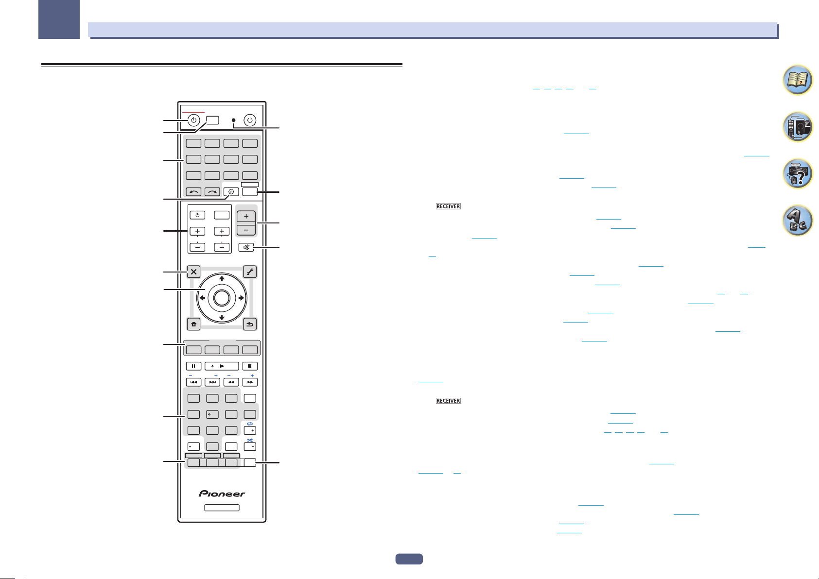
Remote control
This section explains how to operate the remote control for the receiver.
2,3
10
ALL ZONE STBY
STANDBY/ON
1
4
DISCRETE ON
RCU SETUP
BD DVDDVR
CDTV
USB CBL
SATTUNERMHL
iPod
INPUT
SELECT
5
TV CONTROL
6
7
CH
AUDIO
PARAMETER
TOP MENU
8
HOME
MENU
iPod CTRL
9
5
FEATURES
P.CTRL
PHASE
MPX
PRESET TUNE
AUTO/ALC/
STANDARDADV SURR
DIRECT
2
13
MCACC
SIGNAL SEL
546
DIMMER SLEEP
SPEAKERS
8
79
HDMI OUT
D.ACCESS
0
ZONE 2 ZONE 3
Z2 Z3 HDZ
RECEIVER
SOURCE
BDR
HDMI
NET
ADPT
RECEIVER
STATUS
VOLUME
INPUT
VOL
MUTE
VIDEO
PARAMETER
TOOLS
MENU
ENTER
RETURN
+
PQLS
BAND PTY
+Favorite
AUDIO
AUTO
S.RTRV
CH LEVEL
CLASS
ENTER / CLR
OPTION
HD ZONE
ECO
DISP
CH
CH
11
12
13
14
15
The remote has been conveniently color-coded according to component control using the following system:
! White – Receiver control, TV control
! Blue – Other controls (See pages 43, 44, 46, 47 and 76.)
1 u STANDBY/ON
This switches between standby and on for this receiver.
2 ALL ZONE STBY DISCRETE ON
Use this button to perform unique operations (page 75).
3 RCU SETUP
Use to input the preset code when making remote control settings and to set the remote control mode (page 73).
4 Input function buttons
Press to select control of other components (page 73).
Use INPUT SELECT c/ d to select the input function (page 42).
5 Receiver Control buttons
Press first to access:
! STATUS – Press to check selected receiver settings (page 70).
! AUTO/ALC/DIRECT – Switches between Auto Surround (page 51), Auto Level Control mode and Stream
Direct mode (page 52).
! STANDARD – Press for Standard decoding and to switch various modes (2 Pro Logic, Neo:X, etc.) (page
51).
! ADV SURR – Use to switch between the various surround modes (page 52).
! SIGNAL SEL – Use to select an input signal (page 53).
! MCACC – Press to switch between MCACC presets (page 53).
! CH LEVEL – Press repeatedly to select a channel, then use k/l to adjust the level (pages 42 and 87).
! AUTO S.RTRV – Press to restore CD quality sound to compressed audio sources (page 65).
! SPEAKERS – Use to change the speaker terminal (page 69).
! DIMMER – Dims or brightens the display (page 70).
! SLEEP – Use to put the receiver in sleep mode and select the amount of time before sleep (page 70).
! HDMI OUT – Switch the HDMI output terminal (page 70).
6 TV CONTROL buttons
These buttons can be used to perform operations on the TV to which the TV CONTROL INPUT button is assigned.
The TV can be operated with these buttons regardless of the input set for the remote control’s operation mode
(page 73).
7 Receiver setting buttons
Press first to access:
! AUDIO PARAMETER – Use to access the Audio options (page 65).
! VIDEO PARAMETER – Use to access the Video options (page 67).
! HOME MENU – Use to access the Home Menu (pages 38, 40, 61, 79 and 86).
! RETURN – Press to confirm and exit the current menu screen.
8 i/j/k/l/ENTER
Use the arrow buttons when setting up your surround sound system (see page 79) and the Audio or Video options
(page 65 or 67).
9 FEATURES buttons
These let you operate the receiver’s features directly.
! PHASE – Press to switch on/off Phase Control (page 53).
! P.CTRL+ – Use to switch the setting of the Auto Phase Control Plus function (page 65).
! PQLS – Press to select the PQLS setting (page 62).
! ECO – Use to switch the eco mode type (page 52).
12

02
10 MULTI-ZONE select buttons
Switch to perform operations in ZONE 2 and HDZONE (page 69).
! The ZONE 3 button is not used with this unit.
11 Remote control LED
Lights when a command is sent from the remote control.
12
Switches the remote to control the receiver (used to select the white commands).
Switch to perform operations in the main zone.
Also use this button to set up surround sound.
13 VOLUME +/–
Use to set the listening volume.
14 MUTE
Mutes the sound or restores the sound if it has been muted (adjusting the volume also restores the sound).
15 OPTION
The preset codes of desired devices can be registered in the remote control and button operations can be registered using the learning mode.
Controls and displays
13
02
Controls and displays
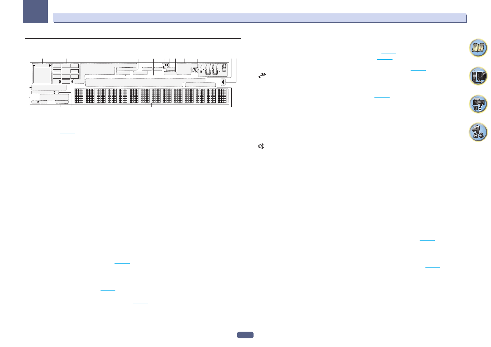
Display
21 3 10 118654 129 14 15
2
AUTO
HDMI
DIGITAL
ANALOG
AUTO SURROUND
STREAM DIRECT
2
PROLOGIC x
ADV.SURROUND
SP AB
8
L C R
SL SR
XL XR
STANDARD
SLEEP
XC
LFE
DIGITAL PLUS
2
TrueHD
DTS HD ES 96/24
CD
MSTR
DSD PCM
MULTI-ZONE
S.RTRV SOUND UP MIX
TUNER
iPod
1 Signal indicators
Light to indicate the currently selected input signal. AUTO lights when the receiver is set to select the input signal automatically (page 53).
2 Program format indicators
Light to indicate the channels to which digital signals are being input.
! L/R – Left front/Right front channel
! C – Center channel
! SL/SR – Left surround/Right surround channel
! LFE – Low frequency effects channel (the (( )) indicators light when an LFE signal is being input)
! XL/XR – Two channels other than the ones above
! XC – Either one channel other than the ones above, the mono surround channel or matrix encode flag
3 Digital format indicators
Light when a signal encoded in the corresponding format is detected.
! 2 DIGITAL – Lights with Dolby Digital decoding.
! 2 DIGITAL PLUS – Lights with Dolby Digital Plus decoding.
! 2 TrueHD – Lights with Dolby TrueHD decoding.
! DTS – Lights with DTS decoding.
! DTS HD – Lights with DTS-HD decoding.
! 96/24 – Lights with DTS 96/24 decoding.
! DSD – Lights when an SACD or a file’s DSD signals are playing.
! DSD PCM – Light during DSD (Direct Stream Digital) to PCM conversion.
! PCM – Lights during playback of PCM signals.
! MSTR – Lights during playback of DTS-HD Master Audio signals.
4 MULTI-ZONE
Lights when the MULTI-ZONE feature is active (page 69).
5 SOUND
Lights when the DIALOG E (Dialog Enhancement) or TONE (tone controls) features is selected (page 65).
6 PQLS
Lights when the PQLS feature is active (page 62).
7 S.RTRV
Lights when the Auto Sound Retriever function is active (page 65).
7 13
PQLS
ALC
AT T
OVER
TV
DVR
VIDEO
HDMI
DVD
BD
20 2117 18 19
TUNED RDS
STEREO
MONO
[ 2 ]
USB
[ 3 ]
dB
[ 4 ]
8 Listening mode indicators
! AUTO SURROUND – Lights when the Auto Surround feature is switched on (page 51).
! ALC – Lights when the ALC (Auto level control) mode is selected (page 51).
16
! STREAM DIRECT – Lights when Direct/Pure Direct is selected (page 52).
! ADV.SURROUND – Lights when one of the Advanced Surround modes has been selected (page 52).
! STANDARD – Lights when one of the Standard Surround modes is switched on (page 51).
9 (PHASE CONTROL)
Lights when the Phase Control is switched on (page 53).
10 ATT
Lights when the input signal level is lowered to reduce distortion (page 65).
11 OVER
Lights when excessive analog signals are being input.
12 Tuner indicators
! TUNED – Lights when a broadcast is being received.
! STEREO – Lights when a stereo FM broadcast is being received in auto stereo mode.
! MONO – Lights when the mono mode is set using MPX.
! RDS – Lights when an RDS broadcast is received.
13
Lights when the sound is muted.
14 Master volume level
Shows the overall volume level.
“---” indicates the minimum level, and “+12dB” indicates the maximum level.
15 Input function indicators
Light to indicate the input function you have selected.
16 Scroll indicators
Light when there are more selectable items when making the various settings.
17 Speaker indicators
Lights to indicate the current speaker system using SPEAKERS (page 69).
18 SLEEP
Lights when the receiver is in sleep mode (page 70).
19 Matrix decoding format indicators
! 2PRO LOGIC IIx – This lights to indicate 2 Pro Logic II / 2 Pro Logic IIx decoding (page 51).
20 Character display
Displays various system information.
21 Remote control mode indicator
Lights to indicate the receiver’s remote control mode setting. (Not displayed when set to 1.) (page 90)
14
02
35
Controls and displays
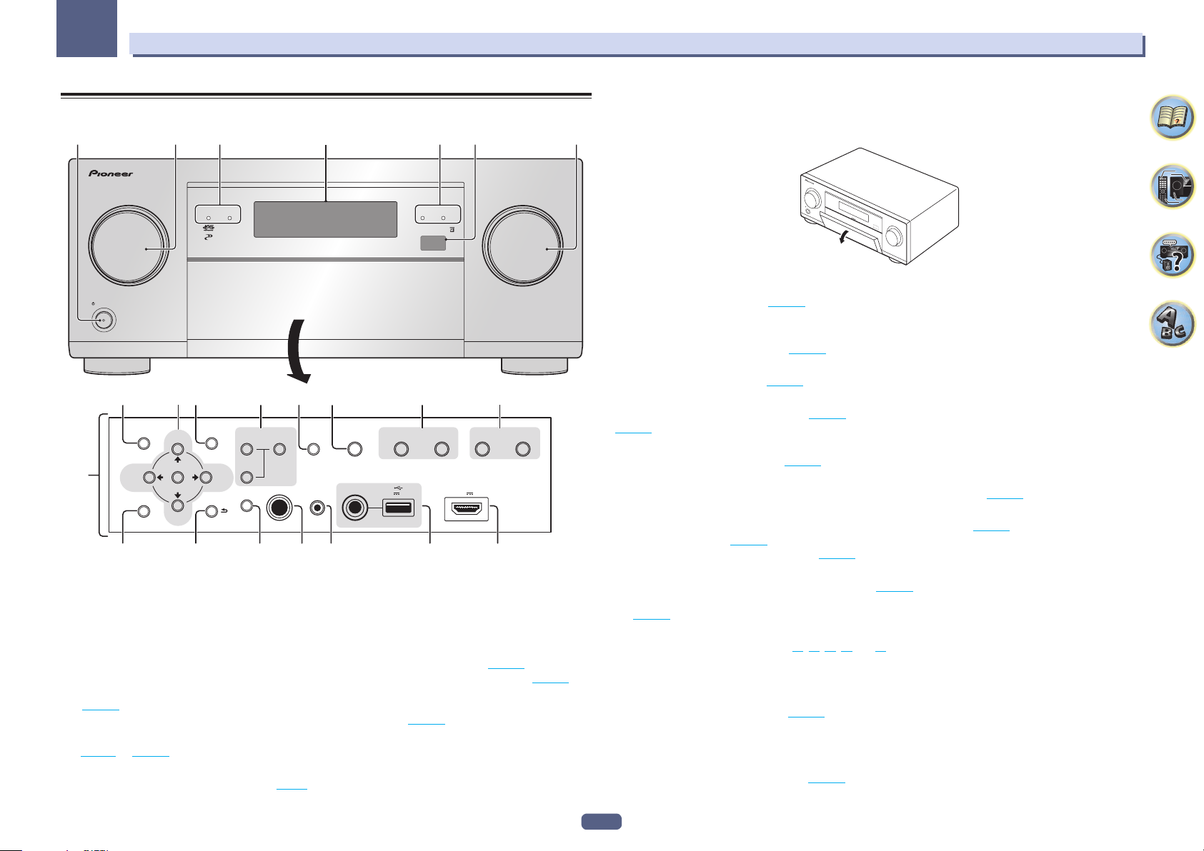
Front panel
1 2 4
ADVANCED
MCACC
FL OFF
INPUT
SELECTOR
STANDBY/ON
8910 1211 13 15
AUDIO
PARAMETER
7
HOME MENU RETURN
16 17 2019 21 22
TUNE
ENTER
TUNE
VIDEO
PARAMETER
PRESETPRESET
ZONE 2
ON/OFF
HDZONE
ON/OFF
PHASE
CONTROL
18
MULTI-ZONE
CONTROL
PHONES
SPEAKERS
MCACC
SETUP MIC
iPod iPhone iPad
DIRECT CONTROL
with USB
AUTO/ALC/
DIRECTECO BAND TUNER EDIT
5V 2.1 A
1 u STANDBY/ON
This switches between standby and on for this receiver.
2 INPUT SELECTOR dial
Use to select an input function.
3 Indicators
! ADVANCED MCACC – Lights when EQ is set to ON in the AUDIO PARAMETER menu (page 65).
! FL OFF – Lights when “off” (nothing displayed) is selected with the display’s dimmer adjustment (page 70).
! HDMI – Blinks when connecting an HDMI-equipped component; lights when the component is connected
(page 25).
! iPod iPhone iPad – Lights to indicate iPod/iPhone/iPad is connected (page 33).
4 Character display
See Display on page 14.
5 Remote sensor
Receives the signals from the remote control (page 9).
14
3
iPod iPhone iPadHDMI
HDMI 5 INPUT/
5V 0.9 A
MHL (
)
MASTER
VOLUME
6 MASTER VOLUME dial
7 Front panel controls
To access the front panel controls, catch the sides of the door with your fingers and pull forward.
6
INPUT
SELECTOR
STANDBY/ON
MASTER
VOLUME
8 AUDIO PARAMETER
Use to access the Audio options (page 65).
9 i/j/k/l (TUNE/PRESET) /ENTER
Use the arrow buttons when setting up your Home Menu. Use TUNE i/j to find radio frequencies and use
PRESET k/l to find preset stations (page 46).
10 VIDEO PARAMETER
Use to access the Video options (page 67).
11 MULTI-ZONE controls
If you’ve made MULTI-ZONE connections (page 31) use these controls to control the sub zone from the main zone
(page 69).
12 SPEAKERS
Use to change the speaker terminal (page 69).
13 iPod iPhone iPad DIRECT CONTROL
Change the receiver’s input to the iPod and enable iPod operations on the iPod (page 43).
14 Listening mode buttons
! AUTO SURR/ALC/STREAM DIRECT – Switches between Auto Surround (page 51), Auto Level Control and
Stream Direct mode (page 52).
! ECO – Use to switch the eco mode type (page 52).
15 TUNER controls
! BAND – Switches between AM and FM radio bands (page 46).
! TUNER EDIT – Use with TUNE i/j, PRESET k/l and ENTER to memorize and name stations for recall
(page 46).
16 HOME MENU
Use to access the Home Menu (pages 40, 38, 61, 79 and 86).
17 RETURN
Press to confirm and exit the current menu screen.
18 PHASE CONTROL
Press to switch on/off Phase Control (page 53).
19 PHONES jack
Use to connect headphones. When the headphones are connected, there is no sound output from the speakers.
20 MCACC SETUP MIC jack
Use to connect the supplied microphone (page 37).
15

02
21 iPod/iPhone/iPad terminals
Use to connect your Apple iPod/iPhone/iPad as an audio and video source (page 33), or connect a USB device for
audio and photo playback (page 34).
22 HDMI input/MHL connector
Use for connection to a compatible HDMI device (Video camera, etc.) (page 34).
An MHL-compatible mobile device can also be connected here using the MHL cable (page 34).
Controls and displays
16

Connecting your equipment
Connecting your equipment .........................................................................................................18
Rear panel ......................................................................................................................................18
Determining the speakers’ application ........................................................................................19
Placing the speakers ...................................................................................................................... 20
Connecting the speakers ...............................................................................................................21
Installing your speaker system ..................................................................................................... 21
Selecting the Speaker system ....................................................................................................... 23
About the audio connection ......................................................................................................... 23
About the video converter ...........................................................................................................24
About HDMI ................................................................................................................................... 24
Connecting your TV and playback components .........................................................................25
Connecting an HDD/DVD recorder, BD recorder and other video sources ............................... 27
Connecting a satellite/cable receiver or other set-top box ........................................................28
Connecting other audio components .......................................................................................... 29
Connecting additional amplifiers ................................................................................................. 29
Connecting AM/FM antennas .......................................................................................................30
MULTI-ZONE setup ........................................................................................................................31
Connecting to the network through LAN interface ...................................................................32
Connecting optional Bluetooth ADAPTER ...................................................................................33
Connecting an iPod........................................................................................................................33
Connecting a USB device ..............................................................................................................34
Connecting an MHL-compatible device ....................................................................................... 34
Connecting an HDMI-equipped component to the front panel input ...................................... 34
Connecting to a wireless LAN ....................................................................................................... 34
Connecting an IR receiver .............................................................................................................35
Plugging in the receiver ................................................................................................................ 35
17
03
Connecting your equipment
Connecting your equipment
This receiver provides you with many connection possibilities, but it doesn’t have to be difficult. This chapter
explains the kinds of components you can connect to make up your home theater system.
CAUTION
! Before making or changing the connections, switch off the power and disconnect the power cord from the
power outlet. Plugging in should be the final step.
! When making connections, also keep the power cords of the devices being connected unplugged from the
power outlets.
! Depending on the device being connected (amplifier, receiver, etc.), the methods of connection and terminal
names may differ from the explanations in this manual. Also refer to the operating instructions of the respective devices.
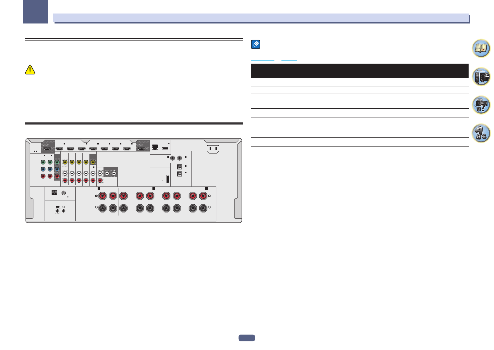
Rear panel
(
HDMI
ASSIGNABLE
1 - 7
ASSIGNABLE
SELECTABLE
1
IN
IN
(
DVR/BDR
(
)
DVD
Y
P
B
R
P
COMPONENT VIDEO
ANTENNA
AM LOOP FM UNBAL 75
OUT 2
(HD ZONE)
2
)
MONITOR
1
IN
(
)
DVD
OUT
OUT
L
R
IR
OUT
IN
2
BD IN
DVDINZONE 2
SAT/CBL
IN
3
IN
IN
(
SAT/CBL
VIDEO
DVR/BDR
IN
AUDIO
SPEAKERS
IN 4IN 6IN
)
(
)
DVR/BDR
MONITOR
OUT
1
IN
FRONT
SUBWOOFER
(CD)
12
ASSIGNABLE
PRE OUT
A A
FRONTCENTER
RL
7
FRONT HEIGHT / FRONT WIDE /
RL
OUT 1
(CONTROL)
OUTPUT 5 V
)
0.6 A MAX
DC OUTPUT
(
)
for WIRELESS LAN
LAN
10/100
1
IN
(
)
DVD
ADAPTER PORT
(
OUTPUT 5 V
)
0.1 A MAX
B
SURROUND BACK
RL
ASSIGNABLE
(Single)
COAXIAL
2
IN
(
SAT/CBL
1
IN
(TV)
ASSIGNABLE
2
IN
(
DVR/BDR
OPTICAL
AC IN
)
)
SURROUND
RL
Note
The input functions below are assigned by default to the receiver’s different input terminals. Refer to The Input
Setup menu on page 38 to change the assignments if other connections are used.
Input function
BD
HDMI Audio Component
(BD)
DVD IN 1 COAX-1 IN 1
SAT/CBL IN 2 COAX-2
DVR/BDR IN 3 OPT-2 IN 2
HDMI 4 IN 4
HDMI 5/MHL
(front panel)
IN 5
HDMI 6 IN 6
HDMI 7 IN 7
TV OPT-1
CD ANALOG-1
Input Terminals
18
03
Connecting your equipment
Determining the speakers’ application
This unit permits you to build various surround systems, in accordance with the number of speakers you have.
! Be sure to connect speakers to the front left and right channels (L and R).
! It is also possible to only connect one of the surround back speakers (SB) or neither.
! If you have two subwoofers, the second subwoofer can be connected to the SUBWOOFER 2 terminal.
Connecting two subwoofers increases the bass sound to achieve more powerful sound reproduction. In this
case, the same sound is output from the two subwoofers.
Choose one from Plans [A] to [E] below.
Important
! The Speaker System setting must be made if you use any of the connections shown below other than [A] (see
Speaker system setting on page 86).
! Sound does not come through simultaneously from the front height, front wide, speaker B and surround back
speakers. Output speakers are different depending on the input signal or listening mode.
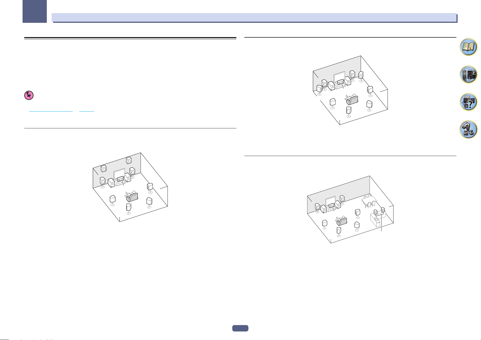
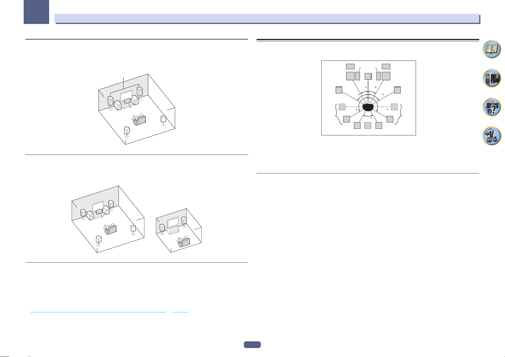
[A] 7.2 channel surround system (Front height)
*Default setting
! Speaker System setting: Normal(SB/FH)
FHR
FHL
L
SW 2
SL
R
SW
1
C
SBL
SR
SBR
[B] 7.2 channel surround system (Front wide)
! Speaker System setting: Normal(SB/FW)
R
SW
1
SBL
FWR
SR
SBR
L
C
SW 2
FWL
SL
This plan replaces the left and right front height speakers shown in [A] with the left and right front wide speakers
(FWL/FWR).
It is not possible to produce sound simultaneously from the front wide speakers and the surround back speakers.
This surround system provides a sound field with good association between the sounds of the different channels.
[C] 7.2 channel surround system & Speaker B connection
! Speaker System setting: Speaker B
R
L
SW
SW 1
C
2
SR
R
L
A 7.2 ch surround system connects the left and right front speakers (L/R), the center speaker (C), the left and right
front height speakers (FHL/FHR), the left and right surround speakers (SL/SR), the left and right surround back
speakers (SBL/SBR), and the subwoofers (SW 1/SW 2).
It is not possible to produce sound simultaneously from the front height speakers and the surround back
speakers.
This surround system produces a more true-to-life sound from above.
SL
SBL
With these connections you can simultaneously enjoy 5.2-channel surround sound in the main zone with stereo
playback of the same sound on the B speakers. The same connections also allow for 7.2-channel surround sound
in the main zone when not using the B speakers.
SBR
Speaker B
19
03
Connecting your equipment
[D] 5.2 channel surround system & Front Bi-amping connection (High quality
surround)
! Speaker System setting: Front Bi-Amp
Bi-amping connection of the front speakers for high sound quality with 5.2-channel surround sound.
Front Bi-Amp
R
L
SW
SW 1
C
2
SR
SL
[E] 5.2 channel surround system & ZONE 2 connection (Multi Zone)
! Speaker System setting: ZONE 2
With these connections you can simultaneously enjoy 5.2-channel surround sound in the main zone with stereo
playback on another component in ZONE 2. (The selection of input devices is limited.)
Main zone
R
L
SW 1
C
2
SW
SR
SL
ZONE 2
Sub zone
R
L
Other speaker connections
! Your favorite speaker connections can be selected even if you have fewer than 5.2 speakers (except front left/
right speakers).
! When not connecting a subwoofer, connect speakers with low frequency reproduction capabilities to the front
channel. (The subwoofer’s low frequency component is played from the front speakers, so the speakers could
be damaged.)
! After connecting, be sure to conduct the Full Auto MCACC (speaker environment setting) procedure. See
Automatically conducting optimum sound tuning (Full Auto MCACC) on page 37.
Placing the speakers
Refer to the chart below for placement of the speakers you intend to connect.
2SW 1
FHL
FWL
SL
! Place the surround speakers at 120º from the center. If you, (1) use the surround back speaker, and, (2) don’t
use the front height speakers / front wide speakers, we recommend placing the surround speaker right beside
you.
! If you intend to connect only one surround back speaker, place it directly behind you.
! Place the left and right front height speakers at least one meter directly above the left and right front speakers.
Some tips for improving sound quality
Where you put your speakers in the room has a big effect on the quality of the sound. The following guidelines
should help you to get the best sound from your system.
! The subwoofer can be placed on the floor. Ideally, the other speakers should be at about ear-level when you’re
listening to them. Putting the speakers on the floor (except the subwoofer), or mounting them very high on a
wall is not recommended.
! For the best stereo effect, place the front speakers 2 m to 3 m apart, at equal distance from the TV.
! If you’re going to place speakers around your CRT TV, use shielded speakers or place the speakers at a suffi-
cient distance from your CRT TV.
! If you’re using a center speaker, place the front speakers at a wider angle. If not, place them at a narrower
angle.
! Place the center speaker above or below the TV so that the sound of the center channel is localized at the TV
screen. Also, make sure the center speaker does not cross the line formed by the leading edge of the front left
and right speakers.
! It is best to angle the speakers towards the listening position. The angle depends on the size of the room. Use
less of an angle for bigger rooms.
! Surround and surround back speakers should be positioned 60 cm to 90 cm higher than your ears and tilted
slightly downward. Make sure the speakers don’t face each other. For DVD-Audio, the speakers should be
more directly behind the listener than for home theater playback.
! Try not to place the surround speakers farther away from the listening position than the front and center speak-
ers. Doing so can weaken the surround sound effect.
SW
C
L
30 30
60
120 120
60
SBL
SB
FHR
R
FWR
60
SR
SBR
20
03
RL
1F
Connecting your equipment
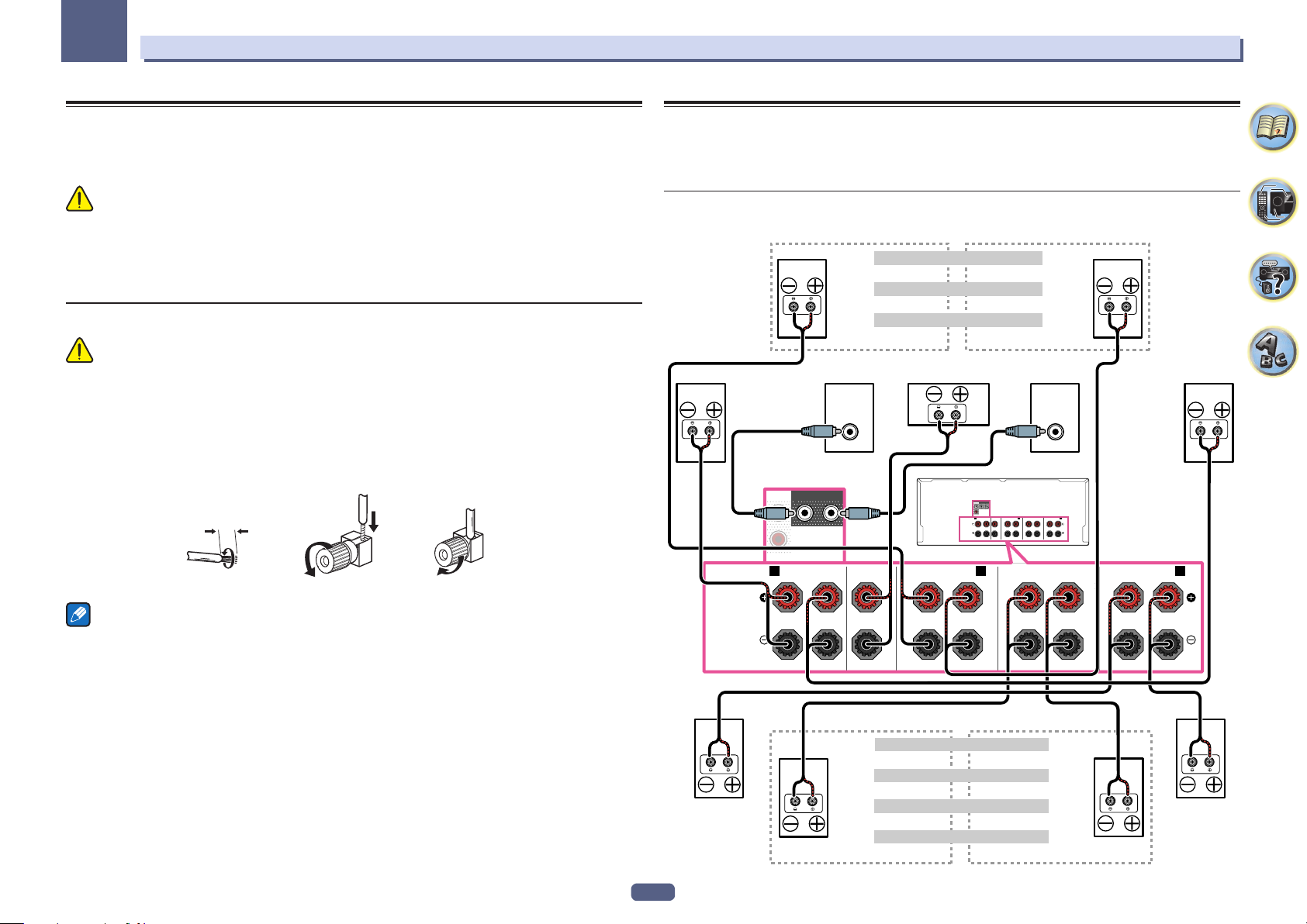
Connecting the speakers
Each speaker connection on the receiver comprises a positive (+) and negative (–) terminal. Make sure to match
these up with the terminals on the speakers themselves.
This unit supports speakers with a nominal impedance of 4 W to 16 W.
CAUTION
! These speaker terminals carry HAZARDOUS LIVE voltage. To prevent the risk of electric shock when con-
necting or disconnecting the speaker cables, disconnect the power cord before touching any uninsulated
parts.
! Make sure that all the bare speaker wire is twisted together and inserted fully into the speaker terminal. If any
of the bare speaker wire touches the back panel it may cause the power to cut off as a safety measure.
Bare wire connections
CAUTION
Make sure that all speakers are securely installed. This not only improves sound quality, but also reduces the risk
of damage or injury resulting from speakers being knocked over or falling in the event of external shocks such as
earthquakes.
1 Twist exposed wire strands together.
2 Loosen terminal and insert exposed wire.
3 Tighten terminal.
123
10 mm
Installing your speaker system
At the very least, front left and right speakers only are necessary. Note that your main surround speakers should
always be connected as a pair, but you can connect just one surround back speaker if you like (it must be connected to the left surround back terminal).
Standard surround connection
The front height terminals can also be used for the front wide and Speaker B speakers.
Front height setting
Front height right Front height left
Front wide right Front wide left
Speaker B - right Speaker B - left
Front right Center Subwoofer 2Subwoofer
LINE LEVEL
INPUT
FRONT
SUBWOOFER
12
PRE OUT
A A
FRONTCENTER
RL
Front wide setting
Speaker B setting
FRONT
SUBWOOFER
12
PRE OUT
A A
FRONTCENTER
FRONT HEIGHT / FRONT WIDE /
RL
RL
SPEAKERS
FRONT HEIGHT / FRONT WIDE /
RL
B
LINE LEVEL
INPUT
B
SURROUNDRLSURROUND BACK
RL
(Single)
SURROUND BACK
RL
(Single)
SURROUND
ront left
Notes
! Please refer to the manual that came with your speakers for details on how to connect the other end of the
speaker cables to your speakers.
! Use an RCA cable to connect the subwoofer. It is not possible to connect using speaker cables.
! If you have two subwoofers, the second subwoofer can be connected to the SUBWOOFER 2 terminal.
Connecting two subwoofers increases the bass sound to achieve more powerful sound reproduction. In this
case, the same sound is output from the two subwoofers.
21
SPEAKERS
Surround right
The surround back terminals can also be used for ZONE 2.
5.2 ch surround setting
Not connected Not connected
6.2 ch surround setting
Not connected Surround back
7.2 ch surround setting
Surround back right Surround back left
ZONE 2 setting
ZONE 2 - Right ZONE 2 - Left
Surround left
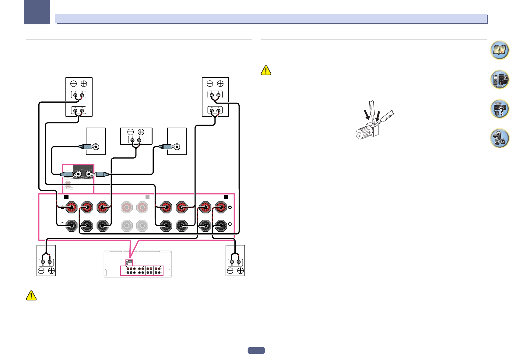
03
Connecting your equipment
Bi-amping your speakers
Bi-amping is when you connect the high frequency driver and low frequency driver of your speakers to different
amplifiers for better crossover performance. Your speakers must be bi-ampable to do this (having separate terminals for high and low) and the sound improvement will depend on the kind of speakers you’re using.
Front right Front left
SPEAKERS
Bi-amp compatible
SUBWOOFER
PRE OUT
speaker
LINE LEVEL
INPUT
Center Subwoofer 2Subwoofer 1
FRONT HEIGHT / FRONT WIDE /
RL
B
High
Low
FRONT
12
A A
FRONTCENTER
RL
Bi-amp compatible
SURROUND BACK
RL
LINE LEVEL
INPUT
speaker
SURROUND
RL
(Single)
High
Low
Bi-wiring your speakers
Your speakers can also be bi-wired if they support bi-amping.
! With these connections, the Speaker System setting makes no difference.
CAUTION
! Don’t connect different speakers from the same terminal in this way.
! When bi-wiring as well, heed the cautions for bi-amping shown above.
% To bi-wire a speaker, connect two speaker cords to the speaker terminal on the receiver.
FRONT
SUBWOOFER
12
PRE OUT
A A
B
SPEAKERS
FRONTCENTER
RL
FRONT HEIGHT / FRONT WIDE /
RL
RL
SURROUNDRLSURROUND BACK
(Single)
Surround leftSurround right
CAUTION
! Most speakers with both High and Low terminals have two metal plates that connect the High to the Low
terminals. These must be removed when you are bi-amping the speakers or you could severely damage the
amplifier. See your speaker manual for more information.
! If your speakers have a removable crossover network, make sure you do not remove it for bi-amping. Doing so
may damage your speakers.
22
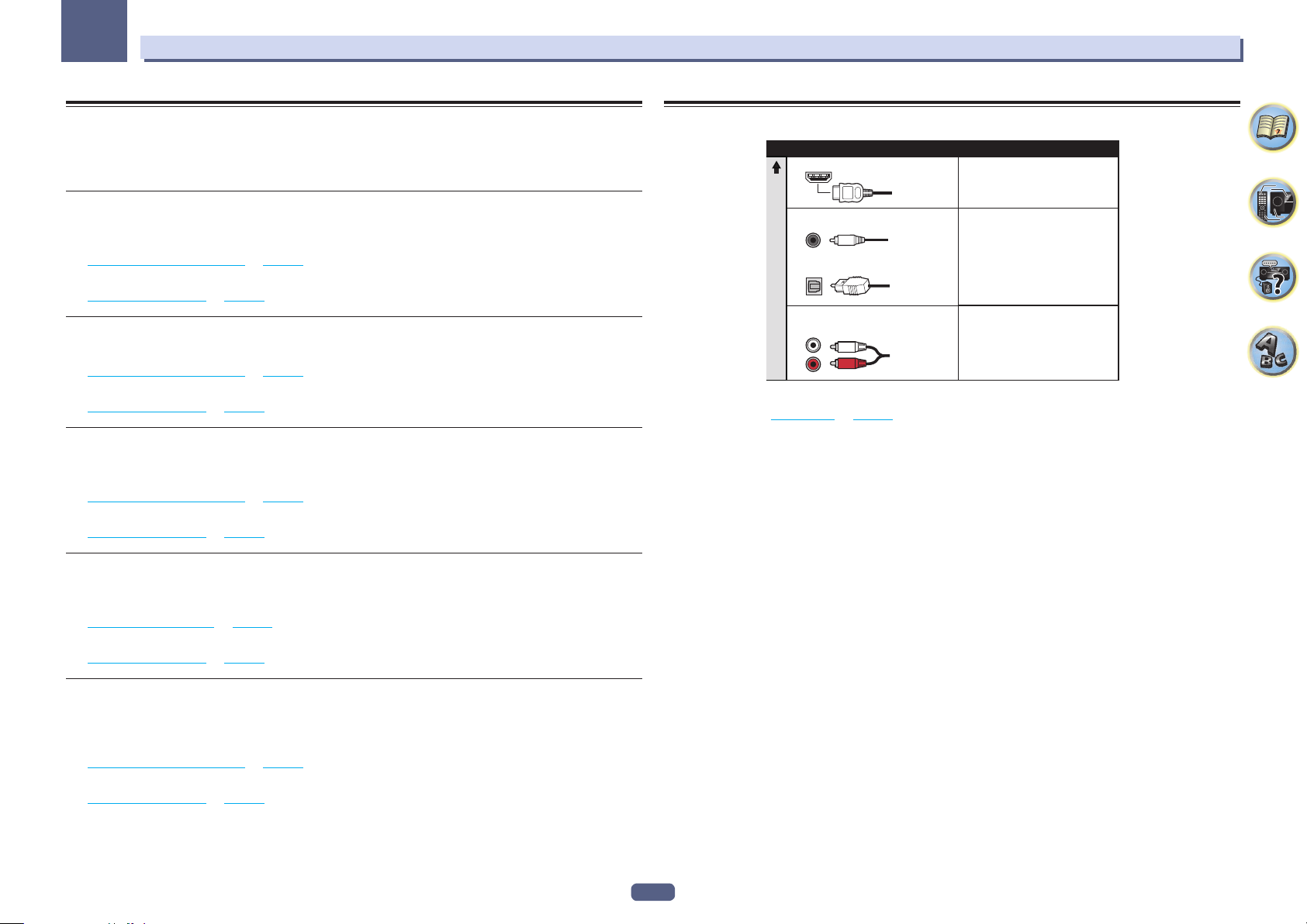
03
Connecting your equipment
Selecting the Speaker system
The front height terminals can be used for front wide and Speaker B connections, in addition to for the front
height speakers. Also, the surround back terminals can be used for bi-amping and ZONE 2 connections, in addition to for the surround back speakers. Make this setting according to the application.
Front height setup
*Default setting
1 Connect a pair of speakers to the front height speaker terminals.
See Standard surround connection on page 21.
2 If necessary, select ‘Normal(SB/FH)’ from the Speaker System menu.
See Speaker system setting on page 86 to do this.
Front wide setup
1 Connect a pair of speakers to the front height speaker terminals.
See Standard surround connection on page 21.
2 Select ‘Normal(SB/FW)’ from the Speaker System menu.
See Speaker system setting on page 86 to do this.
Speaker B setup
You can listen to stereo playback in another room.
1 Connect a pair of speakers to the front height speaker terminals.
See Standard surround connection on page 21.
2 Select ‘Speaker B’ from the Speaker System menu.
See Speaker system setting on page 86 to do this.
Bi-Amping setup
Bi-amping connection of the front speakers for high sound quality with 5.1-channel surround sound.
1 Connect bi-amp compatible speakers to the front and surround back speaker terminals.
See Bi-amping your speakers on page 22.
2 Select ‘Front Bi-Amp’ from the Speaker System menu.
See Speaker system setting on page 86 to do this.
About the audio connection
Types of cables and terminals
HDMI HD audio
Digital (Coaxial) Conventional digital audio
Digital (Optical)
Sound signal priority
RCA (Analog)
(White/Red)
! With an HDMI cable, video and audio signals can be transferred in high quality over a single cable.
! For HD audio, see About HDMI on page 24.
Transferable audio signals
Conventional analog audio
ZONE 2 setup
With these connections you can simultaneously enjoy 5.1-channel surround sound in the main zone with stereo
playback on another component in ZONE 2.
1 Connect a pair of speakers to the surround back speaker terminals.
See Standard surround connection on page 21.
2 Select ‘ZONE 2’ from the Speaker System menu.
See Speaker system setting on page 86 to do this.
23
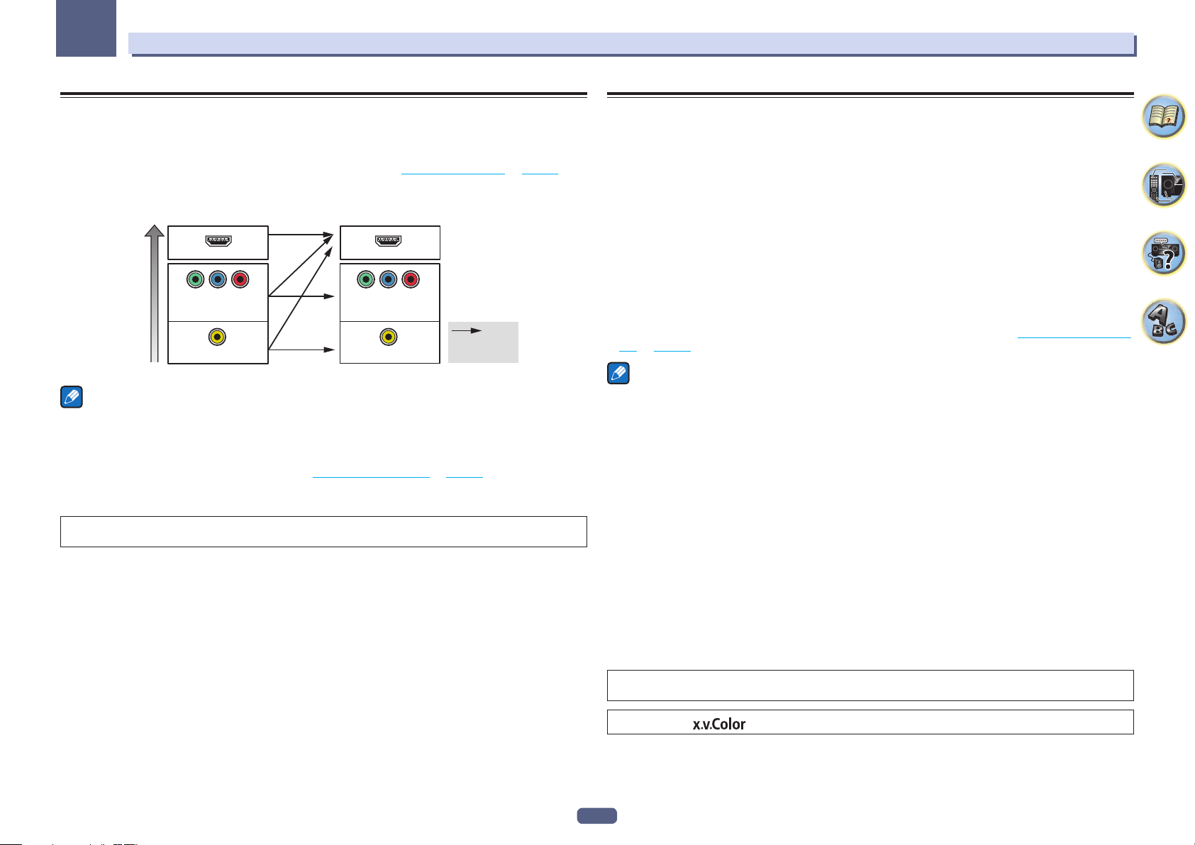
03
Connecting your equipment
About the video converter
The video converter ensures that all video sources are output through the HDMI OUT 1 terminal.
If the TV is only connected to the receiver’s composite VIDEO MONITOR OUT jacks, all the other video devices
must be connected through composite connections.
If several video components are assigned to the same input function (see The Input Setup menu on page 38), the
converter gives priority to HDMI, component, then composite (in that order).
Terminal for connection
with source device
HDMI IN HDMI OUT 1
YPBP
COMPONENT
High picture quality
Notes
! The only exception is HDMI: since this resolution cannot be downsampled, you must connect your monitor/TV
to the receiver’s HDMI output when connecting this video source.
! If the video signal does not appear on your TV, try adjusting the resolution settings on your component or dis-
play. Note that some components (such as video game units) have resolutions that may not be converted. In
this case, try switching Digital Video Conversion (in Setting the Video options on page 67) OFF.
! The signal input resolutions that can be converted from the component video input for the HDMI output are
480i/576i, 480p/576p, 720p and 1080i. 1080p signals cannot be converted.
This item incorporates copy protection technology that is protected by U.S. patents and other intellectual property
rights of Rovi Corporation. Reverse engineering and disassembly are prohibited.
R
VIDEO IN
VIDEO IN
Terminal for connection
with TV monitor
YPBP
COMPONENT VIDEO
MONITOR OUT
MONITOR OUT
R
VIDEO
Video signals
can be output
About HDMI
The HDMI connection transfers uncompressed digital video, as well as almost every kind of digital audio.
This receiver incorporates High-Definition Multimedia Interface (HDMI®/TM) technology.
This receiver supports the functions described below through HDMI connections.
! Digital transfer of uncompressed video (contents protected by HDCP (1080p/24, 1080p/60, etc.))
! 3D signal transfer
! Deep Color signal transfer
! x.v.Color signal transfer
! ARC (Audio Return Channel)
! 4K signal transfer
— This may not operate properly, depending on the connected equipment.
— 4K 24p, 4K 25p and 4K 30p signals are supported.
! Input of multi-channel linear PCM digital audio signals (192 kHz or less) for up to 8 channels
! Input of the following digital audio formats:
— Dolby Digital, Dolby Digital Plus, DTS, High bitrate audio (Dolby TrueHD, DTS-HD Master Audio, DTS-HD
High Resolution Audio), CD, SACD (DSD signal)
! Synchronized operation with components using the Control with HDMI function (see Control with HDMI func-
tion on page 60)
Notes
! An HDMI connection can only be made with DVI-equipped components compatible with both DVI and High
Bandwidth Digital Content Protection (HDCP). If you choose to connect to a DVI connector, you will need a
separate adaptor (DVIdHDMI) to do so. A DVI connection, however, does not support audio signals. Consult
your local audio dealer for more information.
! If you connect a component that is not compatible with HDCP, an HDCP ERROR message is displayed on
the front panel display. Some components that are compatible with HDCP still cause this message to be displayed, but so long as there is no problem with displaying video this is not a malfunction.
! Depending on the component you have connected, using a DVI connection may result in unreliable signal
transfers.
! This receiver supports SACD, Dolby Digital Plus, Dolby TrueHD and DTS-HD Master Audio. To take advantage
of these formats, however, make sure that the component connected to this receiver also supports the corresponding format.
! Use a High Speed HDMI®/TM cable. If an HDMI cable other than a High Speed HDMI®/TM cable is used, it may
not work properly.
! When an HDMI cable with a built-in equalizer is connected, it may not operate properly.
! Signal transfer is only possible when connected to a compatible component.
! HDMI format digital audio transmissions require a longer time to be recognized. Due to this, interruption in the
audio may occur when switching between audio formats or beginning playback.
! Turning on/off the device connected to this unit’s HDMI OUT terminal during playback, or disconnecting/con-
necting the HDMI cable during playback, may cause noise or interrupted audio.
The terms HDMI and HDMI High-Definition Multimedia Interface, and the HDMI Logo are trademarks or registered
trademarks of HDMI Licensing, LLC in the United States and other countries.
“x.v.Color” and are trademarks of Sony Corporation.
24
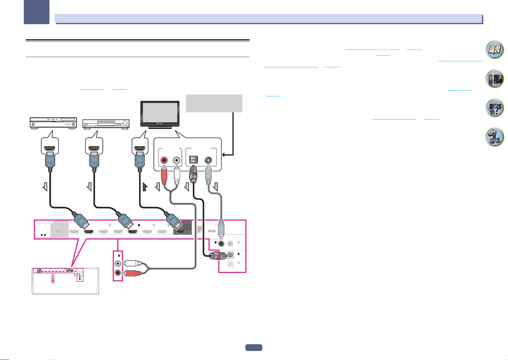
03
Connecting your equipment
Connecting your TV and playback components
Connecting using HDMI
If you have an HDMI or DVI (with HDCP) equipped component (Blu-ray Disc player (BD), etc.), you can connect it
to this receiver using a commercially available HDMI cable.
If the TV and playback components support the Control with HDMI feature, the convenient Control with HDMI
functions can be used (see HDMI Setup on page 61).
This connection is required in
order to listen to the sound of
HDMI/DVI-compatible
Blu-ray Disc player
Other HDMI/DVIequipped component
HDMI INHDMI OUT HDMI OUT
AUDIO OUT
RL
ANALOG
the TV over the receiver.
HDMI/DVI-compatible
monitor
Select one
DIGITAL OUT
COAXIALOPTICAL
! When connecting to an HDMI/DVI-compatible monitor using the HDMI OUT 2 terminal, switch the HDMI
output setting to OUT 2 or OUT 1+2. See Switching the HDMI output on page 70.
Also, MAIN/HDZONE must be set to MAIN beforehand (page 91).
! For input components, connections other than HDMI connections are also possible (see Connecting your DVD
player with no HDMI output on page 26).
! If you want to listen to the sound of the TV over the receiver, connect the receiver and TV with audio cables.
— When the TV and receiver are connected by HDMI connections, if the TV supports the HDMI ARC (Audio
Return Channel) function, the sound of the TV can be input to the receiver via the HDMI OUT 1 terminal, so
there is no need to connect an audio cable. In this case, set ARC at HDMI Setup to ON (see HDMI Setup on
page 61).
After setting the ARC, some time may be required for the connected device to be recognized and the sound to
be produced.
— If you use a coaxial digital audio cable or RCA (analog) audio cable, you’ll need to tell the receiver which digi-
tal or analog audio input you connected the TV to (see The Input Setup menu on page 38).
— Please refer to the TV’s operation manual for directions on connections and setup for the TV.
HDMI
ASSIGNABLE
1 - 7
HDMI
ASSIGNABLE
1 - 7
OUT 2
(HD ZONE)
SELECTABLE
(
LAN
(
10/100
OUTPUT 5 V
0.6 A MAX
DC OUTPUT
)
for WIRELESS LAN
)
ASSIGNABLE
COAXIAL
2
IN
(
SAT/CBL
1
IN
(TV)
ASSIGNABLE
2
IN
(
DVR/BDR
OPTICAL
)
)
1
IN
(
)
DVD
OUT 2
(HD ZONE)
SELECTABLE
1
2
3
IN
BD IN
IN
IN
IN 4IN 6IN
(
)
(
)
(
)
DVD
SAT/CBL
DVR/BDR
1
IN
(CD)
ASSIGNABLE
1
IN
(
)
DVD
(
OUTPUT 5 V
7
OUT 1
)
0.6 A MAX
(CONTROL)
DC OUTPUT
(
)
for WIRELESS LAN
LAN
10/100
COAXIAL
1
2
IN
IN
(
)
(
)
DVD
SAT/CBL
ASSIGNABLE
1
IN
(TV)
ASSIGNABLE
2
IN
(
)
DVR/BDR
OPTICAL
BD IN
2
IN
(
SAT/CBL
)
IN
(CD)
ASSIGNABLE
1
3
IN
(
DVR/BDR
IN 4IN 6IN
)
7
OUT 1
(CONTROL)
25
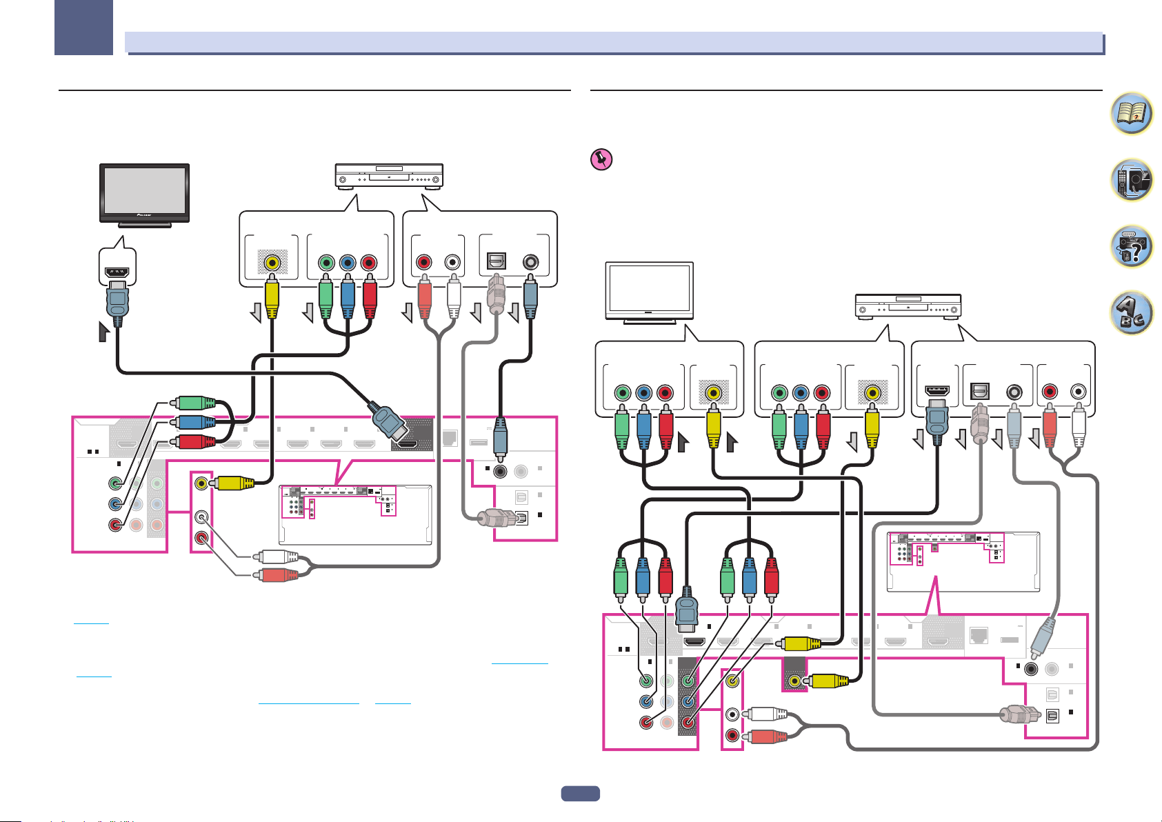
03
RL
Connecting your equipment
Connecting your DVD player with no HDMI output
This diagram shows connections of a TV (with HDMI input) and DVD player (or other playback component with no
HDMI output) to the receiver.
HDMI/DVI-compatible monitor
HDMI IN
HDMI
ASSIGNABLE
1 - 7
ASSIGNABLE
OUT 2
(HD ZONE)
SELECTABLE
1
IN
IN
(
DVR/BDR
(
)
DVD
Y
P
B
R
P
COMPONENT VIDEO
1
IN
(
)
DVD
MONITOR
2
OUT
)
Select one
VIDEO OUT
VIDEO
2
BD IN
IN
IN
(
)
(
SAT/CBL
DVR/BDR
DVD
IN
COMPONENT VIDEO OUT
3
IN 4IN 6IN
)
1
OUT 2
IN
BD IN
HDMI
(HD ZONE)
(
)
DVD
ASSIGNABLE
1 - 7
SELECTABLE
MONITOR
1
2
IN
IN
OUT
(
)
DVR/BDR
(
)
DVD
ASSIGNABLE
Y
DVD
P
B
IN
R
P
COMPONENT VIDEO
Y
2
3
IN
IN
(
)
(
SAT/CBL
DVR/BDR
)
IN 4IN 6IN
PB
7
DVD player, etc.
PR
7
(
OUTPUT 5 V
OUT 1
)
0.6 A MAX
(CONTROL)
DC OUTPUT
(
)
for WIRELESS LAN
10/100
LAN
COAXIAL
1
2
IN
IN
(
)
(
)
DVD
SAT/CBL
ASSIGNABLE
1
IN
(TV)
ASSIGNABLE
2
IN
(
)
DVR/BDR
OPTICAL
Select one
AUDIO OUT
RL
ANALOG
(
OUT 1
(CONTROL)
OUTPUT 5 V
0.6 A MAX
DC OUTPUT
(
)
for WIRELESS LAN
10/100
LAN
IN
(
DVD
)
1
)
DIGITAL OUT
COAXIALOPTICAL
ASSIGNABLE
COAXIAL
2
IN
(
SAT/CBL
1
IN
(TV)
ASSIGNABLE
2
IN
(
DVR/BDR
OPTICAL
)
)
Connecting your TV with no HDMI input
This diagram shows connections of a TV (with no HDMI input) and DVD player (or other playback component) to
the receiver.
Important
! With these connections, the picture is not output to the TV even if the DVD player is connected with an HDMI
cable. Connect the receiver and TV using the same type of video cable as used to connect the receiver and
player.
! Also, when the receiver and TV are connected by anything other than an HDMI cable, the OSD function allow-
ing display of the receiver’s settings, operations, etc., on the TV’s screen cannot be used. In this case, watch
the receiver’s front panel display while performing the various operations and making settings.
DVD player, etc.
TV
COMPONENT VIDEO IN
PR
P
B
Y
VIDEO IN
VIDEO
COMPONENT VIDEO OUT
Select oneSelect one
PR
P
B
Y
VIDEO OUT
VIDEO
HDMI OUT
1
2
OUT 2
IN
BD IN
IN
HDMI
(HD ZONE)
(
)
(
)
DVD
SAT/CBL
ASSIGNABLE
1 - 7
SELECTABLE
MONITOR
MONITOR
1
2
IN
IN
OUT
OUT
(
)
DVR/BDR
(
)
DVD
ASSIGNABLE
Y
DVD
P
B
IN
R
P
COMPONENT VIDEO
Select one
DIGITAL OUT
COAXIALOPTICAL
(
IN 4IN 6IN
)
OUTPUT 5 V
7
OUT 1
)
0.6 A MAX
(CONTROL)
DC OUTPUT
(
)
for WIRELESS LAN
LAN
10/100
COAXIAL
1
2
IN
IN
(
)
(
)
DVD
SAT/CBL
ASSIGNABLE
1
IN
(TV)
ASSIGNABLE
2
IN
(
)
DVR/BDR
OPTICAL
3
IN
(
DVR/BDR
AUDIO OUT
ANALOG
! If you want to listen to the sound of the TV over the receiver, connect the receiver and TV with audio cables
(page 25).
— When the TV and receiver are connected by HDMI connections, if the TV supports the HDMI ARC (Audio
Return Channel) function, the sound of the TV can be input to the receiver via the HDMI OUT 1 terminal, so
there is no need to connect an audio cable. In this case, set ARC at HDMI Setup to ON (see HDMI Setup on
page 61).
! If you use an optical digital audio cable or RCA (analog) audio cable, you’ll need to tell the receiver which digi-
tal input you connected the player to (see The Input Setup menu on page 38).
26
HDMI
ASSIGNABLE
1 - 7
ASSIGNABLE
OUT 2
(HD ZONE)
SELECTABLE
1
IN
IN
(
DVR/BDR
(
)
DVD
Y
P
B
P
R
COMPONENT VIDEO
(
LAN
(
10/100
OUTPUT 5 V
0.6 A MAX
DC OUTPUT
)
for WIRELESS LAN
)
ASSIGNABLE
COAXIAL
2
IN
(
SAT/CBL
1
IN
(TV)
ASSIGNABLE
2
IN
(
DVR/BDR
OPTICAL
)
)
1
IN
(
)
DVD
2
1
BD IN
IN
(
)
DVD
MONITOR
2
OUT
)
DVD
IN
IN
(
SAT/CBL
)
MONITOR
OUT
3
IN
(
DVR/BDR
)
IN 4IN 6IN
7
OUT 1
(CONTROL)
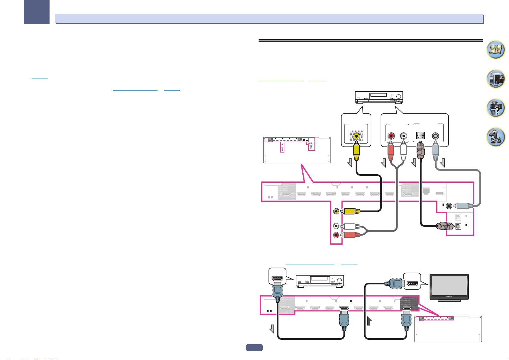
03
Connecting your equipment
! In order to listening to HD audio with this receiver, connect an HDMI cable, and use analog video cable for
video signal input.
Depending on the player, it may not be possible to output video signals to both HDMI and other video output
(composite, etc.) simultaneously, and it may be necessary to make video output settings. Please refer to the
operating instructions supplied with your player for more information.
! If you want to listen to the sound of the TV over the receiver, connect the receiver and TV with audio cables
(page 25).
! If you use an optical digital audio cable or RCA (analog) audio cable, you’ll need to tell the receiver which digi-
tal input you connected the player to (see The Input Setup menu on page 38).
Connecting an HDD/DVD recorder, BD recorder and other video
sources
This receiver has audio/video inputs suitable for connecting analog or digital video devices, including HDD/DVD
recorders and BD recorders.
When you set up the receiver you’ll need to tell the receiver which input you connected the recorder to (see also
The Input Setup menu on page 38).
HDD/DVD recorder, BD recorder, etc.
Select one
AUDIO OUT
RL
ANALOG
7
OUT 1
(CONTROL)
DIGITAL OUT
COAXIALOPTICAL
(
10/100
LAN
(
OUTPUT 5 V
0.6 A MAX
DC OUTPUT
)
for WIRELESS LAN
)
ASSIGNABLE
COAXIAL
2
IN
(
SAT/CBL
1
IN
(TV)
ASSIGNABLE
2
IN
(
DVR/BDR
OPTICAL
)
)
1
IN
(
)
DVD
OUT 2
HDMI
(HD ZONE)
ASSIGNABLE
1 - 7
SELECTABLE
HDMI
ASSIGNABLE
1 - 7
VIDEO OUT
VIDEO
(
IN 4IN 6IN
)
OUT 2
(HD ZONE)
OUTPUT 5 V
7
OUT 1
)
0.6 A MAX
(CONTROL)
DC OUTPUT
(
)
for WIRELESS LAN
10/100
LAN
COAXIAL
1
2
IN
IN
(
)
(
)
DVD
SAT/CBL
ASSIGNABLE
1
IN
(TV)
ASSIGNABLE
2
IN
(
)
DVR/BDR
OPTICAL
1
IN
(
)
DVD
BD IN
2
IN
(
SAT/CBL
3
IN
(
DVR/BDR
)
IN 4IN 6IN
)
VIDEO
DVR/BDR
IN
1
2
3
IN
BD IN
IN
IN
(
)
(
)
(
DVD
SAT/CBL
DVR/BDR
VIDEO
DVR/BDR
IN
AUDIO
SELECTABLE
AUDIO
! If your HDD/DVD recorder, BD recorder, etc., is equipped with an HDMI output terminal, we recommend con-
necting it to the receiver’s HDMI DVR/BDR IN terminal. When doing so, also connect the receiver and TV by
HDMI (see Connecting using HDMI on page 25).
HDMI/DVI-compatible monitor
HDMI IN
OUT 1
(CONTROL)
1
2
OUT 2
IN
BD IN
IN
HDMI
ASSIGNABLE
1 - 7
IN
(HD ZONE)
(
)
(
)
(
DVD
SAT/CBL
DVR/BDR
SELECTABLE
3
)
IN 4IN 6IN
7
OUT 1
(CONTROL)
HDMI
ASSIGNABLE
1 - 7
HDMI OUT
HDD/DVD recorder, BD recorder, etc.
1
IN
BD IN
(
)
DVD
SELECTABLE
OUT 2
(HD ZONE)
2
IN
(
SAT/CBL
3
IN
(
DVR/BDR
)
IN 4IN 6IN
)
7
27
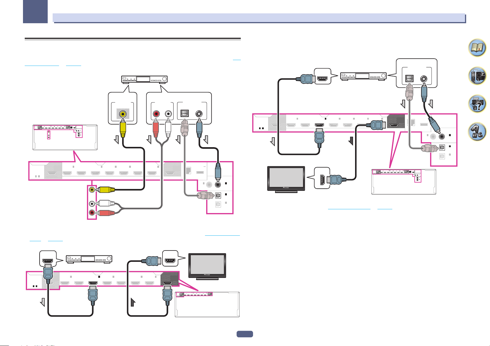
03
Connecting your equipment
Connecting a satellite/cable receiver or other set-top box
Satellite and cable receivers, and terrestrial digital TV tuners are all examples of so-called ‘set-top boxes’.
When you set up the receiver you’ll need to tell the receiver which input you connected the set-top box to (see The
Input Setup menu on page 38).
STB
Select one
AUDIO OUT
RL
ANALOG
7
OUT 1
(CONTROL)
DIGITAL OUT
(
LAN
10/100
COAXIALOPTICAL
(
OUTPUT 5 V
0.6 A MAX
DC OUTPUT
)
for WIRELESS LAN
)
ASSIGNABLE
COAXIAL
2
IN
(
SAT/CBL
1
IN
(TV)
ASSIGNABLE
2
IN
(
DVR/BDR
OPTICAL
)
)
1
IN
(
)
DVD
HDMI
ASSIGNABLE
1 - 7
SELECTABLE
HDMI
ASSIGNABLE
1 - 7
VIDEO OUT
VIDEO
(
IN 4IN 6IN
)
OUTPUT 5 V
7
OUT 1
)
0.6 A MAX
(CONTROL)
DC OUTPUT
(
)
for WIRELESS LAN
LAN
10/100
COAXIAL
1
2
IN
IN
(
)
(
)
DVD
SAT/CBL
ASSIGNABLE
1
IN
(TV)
ASSIGNABLE
2
IN
(
)
DVR/BDR
OPTICAL
1
IN
BD IN
(
)
DVD
SAT/CBL
IN
2
IN
(
SAT/CBL
3
IN
(
DVR/BDR
)
IN 4IN 6IN
)
1
2
3
OUT 2
IN
BD IN
IN
IN
(HD ZONE)
(
)
(
)
(
DVD
SAT/CBL
DVR/BDR
SAT/CBL
IN
OUT 2
(HD ZONE)
SELECTABLE
! Even if your set-top box is equipped with an HDMI output terminal, in some cases the sound is output from
the digital audio output (optical or coaxial) and only the video is output from the HDMI output terminal. In this
case, make the HDMI and digital audio connections as shown below.
Select one
IN
(
DVR/BDR
3
)
OUT 1
(CONTROL)
IN 4IN 6IN
LAN
7
OUT 1
(CONTROL)
DIGITAL OUT
COAXIALOPTICAL
(
OUTPUT 5 V
0.6 A MAX
DC OUTPUT
(
)
for WIRELESS LAN
10/100
(
OUTPUT 5 V
)
0.6 A MAX
DC OUTPUT
(
)
for WIRELESS LAN
10/100
LAN
COAXIAL
1
IN
IN
(
)
(
DVD
SAT/CBL
ASSIGNABLE
IN
(TV)
ASSIGNABLE
IN
(
DVR/BDR
OPTICAL
)
ASSIGNABLE
COAXIAL
2
IN
(
SAT/CBL
1
IN
(TV)
ASSIGNABLE
2
IN
(
DVR/BDR
OPTICAL
)
)
1
IN
(
)
DVD
2
)
1
2
)
HDMI
ASSIGNABLE
1 - 7
SELECTABLE
OUT 2
(HD ZONE)
1
IN
(
)
DVD
HDMI/DVI-compatible monitor
BD IN
HDMI OUT
IN
(
SAT/CBL
HDMI IN
STB
2
3
IN
(
DVR/BDR
)
IN 4IN 6IN
)
7
1
2
OUT 2
IN
BD IN
IN
HDMI
(HD ZONE)
(
)
(
)
DVD
SAT/CBL
ASSIGNABLE
1 - 7
SELECTABLE
— If you use a digital audio cable or RCA (analog) audio cable, you’ll need to tell the receiver which digital input
you connected the set-top box to (see The Input Setup menu on page 38).
! If your set-top box is equipped with an HDMI output terminal, we recommend connecting it to the receiver’s
HDMI SAT/CBL IN terminal. When doing so, also connect the receiver and TV by HDMI (see Connecting using
HDMI on page 25).
HDMI/DVI-compatible monitor
OUT 1
(CONTROL)
1
2
3
OUT 2
IN
BD IN
IN
IN
HDMI
ASSIGNABLE
1 - 7
SELECTABLE
IN 4IN 6IN
(HD ZONE)
(
)
(
)
(
)
DVD
SAT/CBL
DVR/BDR
7
OUT 1
(CONTROL)
HDMI
ASSIGNABLE
1 - 7
HDMI OUT
SELECTABLE
OUT 2
(HD ZONE)
STB
1
IN
(
)
DVD
BD IN
2
IN
(
SAT/CBL
3
IN
(
DVR/BDR
)
IN 4IN 6IN
)
HDMI IN
7
28
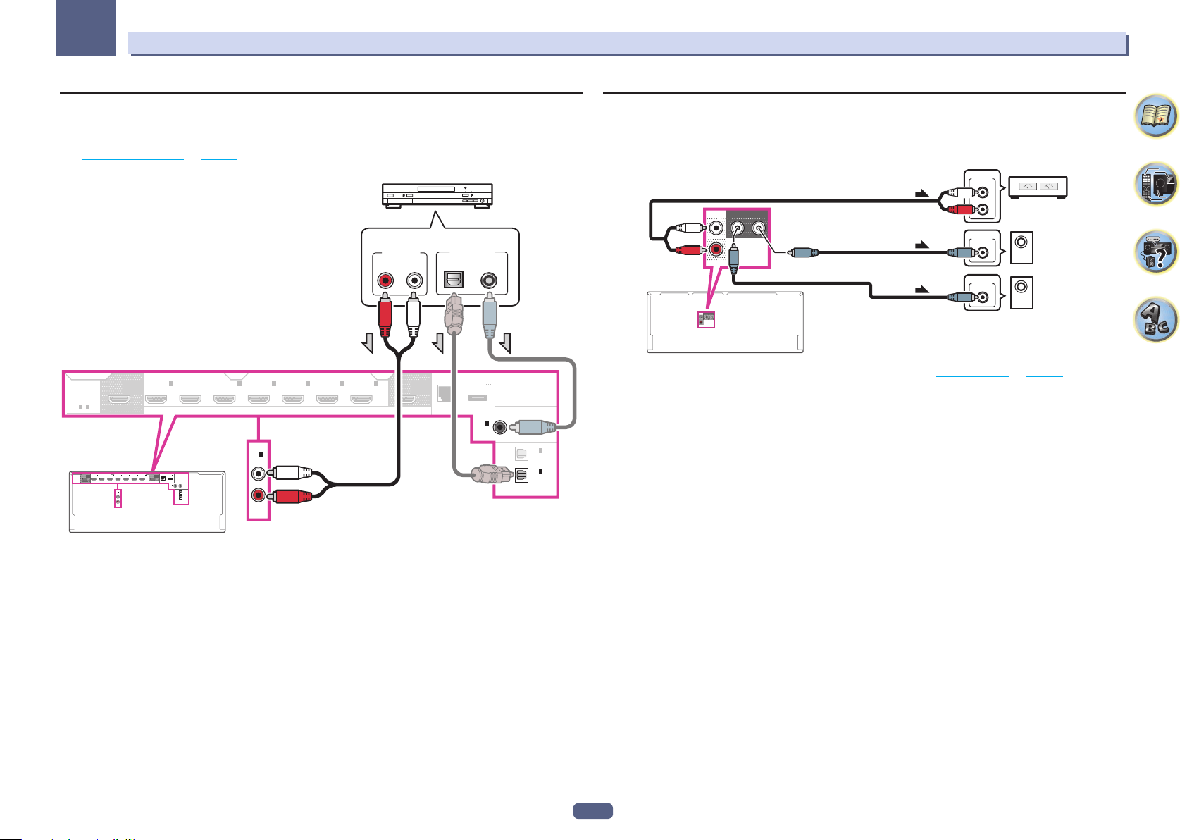
03
Connecting your equipment
Connecting other audio components
This receiver has both digital and analog inputs, allowing you to connect audio components for playback.
When you set up the receiver you’ll need to tell the receiver which input you connected the component to (see
also The Input Setup menu on page 38).
CD player, etc.
Select one
HDMI
ASSIGNABLE
1 - 7
OUT 2
HDMI
(HD ZONE)
ASSIGNABLE
1 - 7
SELECTABLE
AUDIO OUT
RL
ANALOG
IN 4IN 6IN
1
IN
(
)
DVD
(
OUTPUT 5 V
7
OUT 1
)
0.6 A MAX
(CONTROL)
DC OUTPUT
(
)
for WIRELESS LAN
LAN
10/100
COAXIAL
1
2
IN
IN
(
)
(
)
DVD
SAT/CBL
ASSIGNABLE
1
IN
(TV)
ASSIGNABLE
2
IN
(
)
DVR/BDR
OPTICAL
OUT 2
(HD ZONE)
SELECTABLE
1
2
3
IN
BD IN
IN
IN
(
)
(
)
(
)
DVD
SAT/CBL
DVR/BDR
1
IN
(CD)
ASSIGNABLE
BD IN
2
IN
(
SAT/CBL
)
IN
(CD)
ASSIGNABLE
IN
(
DVR/BDR
1
3
IN 4IN 6IN
)
7
OUT 1
(CONTROL)
LAN
DIGITAL OUT
(
OUTPUT 5 V
0.6 A MAX
(
)
10/100
COAXIALOPTICAL
)
DC OUTPUT
for WIRELESS LAN
IN
(
DVD
1
COAXIAL
2
ASSIGNABLE
IN
(
SAT/CBL
1
IN
(TV)
ASSIGNABLE
2
IN
(
DVR/BDR
OPTICAL
)
)
)
Connecting additional amplifiers
This receiver has more than enough power for any home use, but it’s possible to add additional amplifiers to front
and subwoofer channels of your system using the pre-outs. Make the connections shown below to add amplifiers
to power your speakers.
ANALOG
INPUT
L
Front channel
ANALOG
INPUT
ANALOG
INPUT
R
amplifier
Powered
subwoofer 2
Powered
subwoofer 1
FRONT
SUBWOOFER
12
PRE OUT
FRONT
SUBWOOFER
12
PRE OUT
! If you’re not using a subwoofer, change the front speaker setting (see Speaker Setting on page 83) to LARGE.
! If you have two subwoofers, the second subwoofer can be connected to the SUBWOOFER 2 terminal.
Connecting two subwoofers increases the bass sound to achieve more powerful sound reproduction. In this
case, the same sound is output from the two subwoofers.
! To hear sound only from the pre-outs, switch the speaker terminals to SP: OFF (page 69) or simply disconnect
any speakers that are connected directly to the receiver.
! If your turntable has line-level outputs (i.e., it has a built-in phono pre-amp), connect it to the ANALOG IN 1
(CD) inputs instead.
29
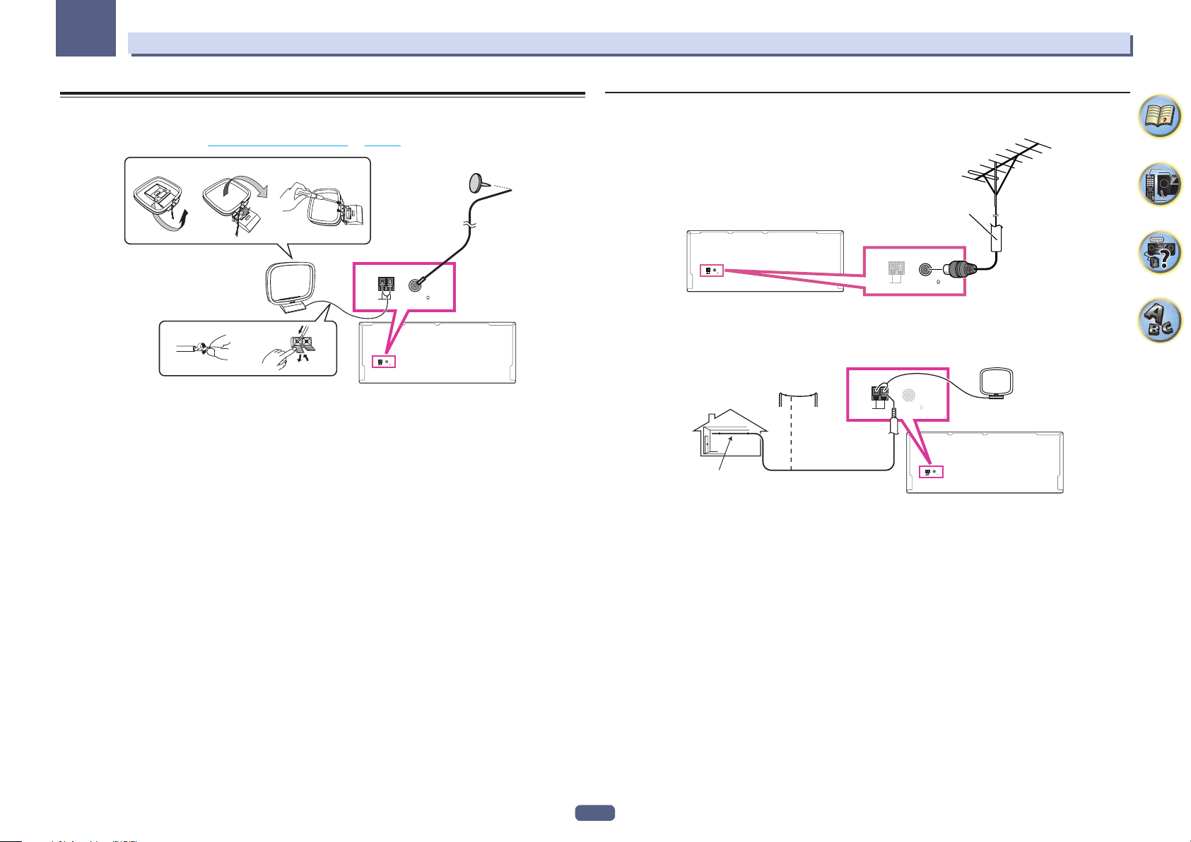
03
Connecting your equipment
Connecting AM/FM antennas
Connect the AM loop antenna and the FM wire antenna as shown below. To improve reception and sound quality,
connect external antennas (see Connecting external antennas on page 30).
ab c
3
ANTENNA
AM LOOP FM UNBAL 75
4
1
1 Pull off the protective shields of both AM antenna wires.
2 Push open the tabs, then insert one wire fully into each terminal, then release the tabs to
secure the AM antenna wires.
3 Fix the AM loop antenna to the attached stand.
To fix the stand to the antenna, bend in the direction indicated by the arrow (fig. a) then clip the loop onto the
stand (fig. b).
! If you plan to mount the AM antenna to a wall or other surface, secure the stand with screws (fig. c) before
clipping the loop to the stand. Make sure the reception is clear.
4 Place the AM antenna on a flat surface and in a direction giving the best reception.
5 Connect the FM wire antenna into the FM antenna socket.
For best results, extend the FM antenna fully and fix to a wall or door frame. Don’t drape loosely or leave coiled up.
2
ANTENNA
AM LOOP FM UNBAL 75
5
Connecting external antennas
To improve FM reception, connect an external FM antenna to FM UNBAL 75 W.
75 Ω coaxial cable
ANTENNA
AM LOOP FM UNBAL 75
To improve AM reception, connect a 5 m to 6 m length of vinyl-coated wire to the AM LOOP terminals without
disconnecting the supplied AM loop antenna.
For the best possible reception, suspend horizontally outdoors.
Outdoor antenna
Indoor antenna
(vinyl-coated wire)
5 m to 6 m
ANTENNA
AM LOOP FM UNBAL 75
ANTENNA
AM LOOP FM UNBAL 75
ANTENNA
AM LOOP FM UNBAL 75
30
 Loading...