


PLASMA DISPLAY
ECRAN PLASMA
PLASMA DISPLAY
SCHERNO AL PLASMA
PLASMA DISPLAY
PLASMA DISPLAY
PDP-V402E
Operating Instructions
Mode d’emploi
Bedienungsanleitung
Istruzioni per l’uso
Gebruikssan wijzing
Manual de instrucciones
SAFETY PRECAUTIONS
PRECAUTIONS DE SECURITE
SICHERHEITSMASSNAHMEN
About the installation of this
product:
The Plasma Display is to be installed by a professional with sufficient technical skill. Please have
a company specializing in equipment installation or the dealer
where you bought your Plasma
Display to install it.
Our company is not responsible
for any damage that may occur
as a result of defective installation, wrong use or remodeling of
your Plasma Display. This includes damage caused by natural disasters or the like.
To the dealer:
After completing the installation
of the Plasma Display, hand
these “OPERATING INSTRUCTIONS” to your customer and
explain how to use the unit.
Thank you very much for purchasing this PIONEER product.
Before using your Plasma Display,
please carefully read the “Safety Precautions” and these “Operating Instructions” so you will know how to
operate the Plasma Display properly.
Keep this manual in a safe place. You
will find it useful in the future.
WARNING: TO PREVENT FIRE
OR SHOCK HAZARD, DO NOT EXPOSE
THIS APPLIANCE TO RAIN OR MOISTURE.
Installation de ce produit:
L’écran à plasma doit être installé
par un professionnel possédant les
compétences techniques suffisantes.
Il est vivement recommandé de
faire installer l’écran à plasma par
une société spécialisée dans
l’installation d’équipements de ce
type ou par le revendeur auprès
duquel vous avez acheté ce matériel.
Notre société ne peut être tenue responsable pour tous les dommages éventuels qui pourraient se produire à la suite d’une installation défectueuse, d’une utilisation inappropriée ou d’une rénovation de l’écran
à plasma que vous avez acquis. Ceci
inclut les dommages entraînés par
des désastres naturels ou autres
événements analogues.
Pour le revendeur :
Après avoir terminé l’installation de
l’écran à plasma, vous êtes priés
de remettre cette “Mode d’emploi”
à votre client et de l’informer sur
l’utilisation du matériel.
Nous vous remercions vivement
d’avoir fait l’acquisition de ce
produit PIONEER.
Avant d’utiliser votre écran à
plasma, veuillez lire attentivement
les “Précautions de Sécurité” ainsi
que la présente “Mode d’emploi”
de manière à utiliser l’écran à
plasma correctement.
Conservez ce manuel dans un
endroit sûr. Il vous sera sûrement
utile dans les mois ou les années
qui suivent.
ATTENTION: AFIN DE PREVE-
NIR TOUS RISQUES DE CHOC ELECTRIQUE OU DE DEBUT D'ENCENDIE, NE
PAS EXPOSER CET APPAREIL A L'HUMIDITE OU A LA PLUIE.
Zur Installation dieses Gerätes:
Lassen Sie dieses Gerät nur von
einem Fachmann installieren.
PIONEER haftet nicht für Schäden,
die durch mangelhafte
Installation, unsachgemäßen
Gebrauch oder durch Eingriff oder
Umbau Ihres Displays entstehen.
Dies beinhaltet auch Schäden
durch Naturkatastrophen.
Für den Fachhändler:
Händigen Sie diese
Bedienungsanleitung bitte Ihrem
Kunden aus und erklären Sie ihm
den Umgang mit dem PlasmaDisplay, nachdem Sie das Gerät
installiert haben.
Herzlichen Dank, daß Sie sich für
den Kauf dieses PIONEER
Produktes entschieden haben.
Bevor Sie Ihr Plasma-Display
benutzen, lesen Sie bitte sorgfältig
die Sicherheitsmaßnahmen und
diese Bedienungsanleitung, um
sich über den ordnungsgemäßen
Umgang mit Ihrem Plasma-Display
zu informieren.
Bewahren Sie diese Anleitung an
einem sicheren Ort auf. Sie wird
Ihnen in Zukunft nützliche Dienste
leisten.
WARNUNG: ZUR VERMEIDUNG
VON BRAND ODER STROMSCHLAG
DARF DIESES GERÄT WEDER REGEN
noch FEUCHTIGKEIT AUSGESETZT
WERDEN.
“Warnung: Dieses produkt
entspricht dem EMV-Standard der
Klasse A. Produkte dieser Klasse
sind nur für den industriellen
Einsatz geeignet und dürfen in
Wohnund Gewerbegebieten
nicht ohne ausreichende
Entstörungsmaßnahmen
betrieben werden.”
2
<ARE1348>
En/Fr/Ge
SAFETY PRECAUTIONS
PRECAUTIONS DE SECURITE
SICHERHEITSMASSNAHMEN
The following symbols are found
on labels attached to the product.
They alert the operators and service personnel of this equipment to
any potentially dangerous conditions.
WARNING
This symbol refers to a hazard or
unsafe practice which can result
in severe personal injury or death.
CAUTION
This symbol refers to a hazard or
unsafe practice which can result
in personal injury or property
damage.
WARNING:
THIS APPARATUS MUST BE EARTHED.
CAUTION:
WHEN POSITIONING THIS EQUIPMENT
ENSURE THAT THE MAINS PLUG AND
SOCKET IS EASILY ACCESSIBLE.
WARNING:
This is a Class A product. In a domestic environment this product
may cause radio interference in
which cause the user may be required to take adequate measures.
To ensure proper heat radiation,
distance the unit slightly from other
equipment, walls, etc. (normally
more than 10 cm). Avoid the following installations which will block
vents and cause heat to build up
inside, resulting in fire hazards.
• Do not attempt to fit the unit inside narrow spaces where ventilation is poor
• Do not place on carpet
• Do not cover with cloth, etc.
• Do not place on its side
• Do not place it upside down
• If planning special installation
such as fitting close to the wall,
placing it horizontally, etc., be
sure to consult your Pioneer
dealer first.
Les symboles qui suivent se
trouvent sur les étiquettes
apposées sur le produit. Ils alertent
les utilisateurs de ce matériel ainsi
que le personnel du service aprèsvente sur toutes les situations qui
présentent un danger potentiel.
DANGER
Ce symbole concerne un risque ou
une pratique dangereuse qui peut
entraîner des blessures graves ou
la mort.
ATTENTION
Ce symbole concerne un risque ou
une pratique dangereuse qui peut
entraîner des blessures ou des
dégâts matériels.
AVERTISSEMENT:
EN POSITIONNANT L’EQUIPEMENT,
S’ASSURER QUE LA FICHE ET LA
PRISE DE RACCORDEMENT DE
L’ALIMENTATION SONT FACILEMENT ACCESSIBLES.
AVERTISSEMENT:
Il s’agit d’un produit de classe A.
Dans un environnement
domestique, ce produit risque de
provoquer des interférences radio; dans ce cas, l’utilisateur est
prié d’engager des mesures
adéquates.
Pour garantir un rayonnement
thermique adéquat, placer l’unité à une
certaine distance des autres
équipements, murs, etc. (normalement
à une distance supérieure à 10 cm).
Eviter les modes d’installation décrits ciaprès qui entraînent l’obstruction des
orifices et provoquent une accumulation
de chaleur interne, d’où un risque
d’incendie.
• Ne pas essayer de placer l’unité dans
des espaces réduits et mal ventilés
• Ne pas la placer sur un tapis
• Ne pas la recouvrir d’un tissu etc.
• Ne pas la placer sur le côté
• Ne pas la renverser
• Si une installation spéciale est
envisagée, comme un montage à
proximité immédiate du mur, un
placement horizontal, consulter
d’abord le revendeur Pioneer de votre
région.
Die nachstehenden Symbole
befinden sich auf an dem Gerät
angebrachten Aufklebern. Sie
machen den Benutzer und das
Wartungspersonal auf mögliche
Gefahren aufmerksam.
Warnung
Dieses Symbol weist auf eine
gefährliche oder unsichere
Handlung hin, die zu schweren
Personenschäden oder Tod
führen kann.
Vorsicht
Dieses Symbol weist auf eine
gefährliche oder unsichere
Handlung hin, die zu Personenoder Sachschäden führen kann.
VORSICHT:
Bei der Aufstellung dieses Geräts
ist darauf zu achten, daß
Netzsteckdose und Netzstecker
leicht zugänglich sind.
Warnung:
Dies ist ein Produkt der
Warenklasse A. In Wohngegenden
kann dieses Produkt zu
Funkstörungen führen. In diesem
Fall müssen die entsprechenden
Maßnahmen getroffen werden.
Um eine ausreichende Lüftung zu
gewährleisten, sollte das Gerät im
Mindestabstand von etwas mehr als
10 cm von anderen Geräten, Wänden
usw. aufgestellt werden. Vermeiden
Sie die nachstehenden
Installationsarten, die die Ventilationsschlitze blockieren könnten. Dadurch
könnte im Inneren des Gerätes ein
Wärmestau entstehen, der wiederum
Feuer auslösen könnte.
• Stellen Sie das Gerät nicht in engen
Räumen mit unzureichender
Lüftung auf.
• Stellen Sie das Gerät nicht auf
Teppich bzw. Teppichboden auf.
• Decken Sie das Gerät nicht mit
Decken o. ä. ab.
• Legen Sie das Gerät nicht auf die
Seite.
• Stellen Sie das Gerät nicht auf den
Kopf. Wenn Sie eine spezielle
Installation beabsichtigen, z.B.
unmittelbar an einer Wand, in
horizontaler Position usw., lassen
Sie sich vorher von Ihrem PioneerFachhändler beraten.
3
<ARE1348>
En/Fr/Ge

CONTENTS
SOMMAIRE
INHALT
SAFETY PRECAUTIONS................................. 2
BEFORE USING YOUR PLASMA DISPLAY
SUPPLIED ACCESSORIES .............................6
PANEL FEATURES AND FUNCTIONS
Remote Control Unit ....................................7
Remote Control Case Installation .................7
Control and Rear Panels .............................. 8
Putting Batteries in the Remote
Control Unit ................................................10
Remote Control Operation Range ............ 11
OPERATIONS
VIEWING IMAGES ON YOUR
PLASMA DISPLAY ........................................12
HOW TO ADJUST PICTURE QUALITY
RGB-1 (BNC) or RGB-2 (MINI D-SUB) Input .. 14
With RGB-1, when inputting RGB
output from a unit with a Euro AV
(SCART) terminal ...................................... 18
Video or Y/C Input .....................................22
INSTALLATION AND CONNECTIONS
INSTALLATION
Using the Display with Stands ..................26
Installing the Display on a Wall or
Other Flat Surfaces ....................................27
How to Fit the Display with Cable clamps.. 28
CONNECTIONS
Diagram of Equipment connected ............29
Connecting a Personal Computer
to the Display ............................................. 30
Connecting Video Devices
to the Display ............................................. 34
Connecting the Power Cord ...................... 41
OTHERS
Maintenance ...............................................42
Troubleshooting ......................................... 44
Specifications ............................................. 51
4
<ARE1348>
En

CONTENTS
SOMMAIRE
INHALT
PRECAUTIONS DE SECURITE ....................... 2
AVANT D’UTILISER VOTRE ECRAN A PLASMA
ACCESSOIRES FOURNIS ............................... 6
CARACTERISTIQUES ET FONCTIONS DES
PANNEAUX
Commande à distance ................................. 7
Installation du boîtier de la commande
à distance ...................................................... 7
Panneau de commande et panneau arrière .... 8
Installation des piles dans la
commande à distance................................ 10
Portée de la commande à distance .......... 11
OPERATIONS
VISUALISATION DES IMAGES
SUR L’ECRAN A PLASMA ............................ 12
COMMENT REGLER LA QUALITE DE L’IMAGE
Entrée RGB-1 (BNC) ou
RGB-2 (MINI D-SUB) ................................... 15
Avec RGB-1, lors de la connexion d’une
sortie RGB à une unité équipée d’un
terminal Euro AV (SCART) ........................ 19
Entrée vidéo ou Y/C ................................... 23
SICHERHEITSMASSNAHMEN....................... 2
VOR DER INBETRIEBNAHME IHRES PLASMADISPLAYS
MITGELIEFERTES ZUBEHÖR....................... 6
TASTEN, EINSTELLUNGEN UND FUNKTIONEN
Fernbedienung ........................................... 7
Anbringen des Fernbedienungshalters ...... 7
Anschlüsse und Bedienungstasten .......... 8
Batterien in die Fernbedienung einlegen .... 10
Empfangsbereich der Fernbedienung .... 11
BEDIENUNG
BILDWIEDERGABE AUF IHREM
PLASMA-DISPLAY...................................... 12
EINSTELLEN DER BILDQUALITÄT
RGB-1 (BNC) oder
RGB-2 (MINI D-SUB) Eingang ................. 15
Bei Empfang von RGB-Signalen eines
Geräts mit EURO A/V-Anschluß
(SCART) über RGB-1 ................................ 19
Video oder Y/C Eingang........................... 23
MONTAGE UND ANSCHLÜSSE
INSTALLATION ET RACCORDEMENTS
INSTALLATION
Utilisation de l’écran avec supports ......... 26
Installation de l’écran sur un mur ou
d’autres surfaces plates ............................. 27
Comment équiper l’écran
de serre-câbles ........................................... 28
CONNEXIONS
Schéma de l’équipement connecté .......... 29
Connexion d’un ordinateur personnel
à l’écran ....................................................... 30
Connexion d’équipements vidéo
à l’écran ....................................................... 34
Connexion du cordon d’alimentation....... 41
AUTRES
Maintenance ............................................... 42
Dépannage.................................................. 46
Spécifications ............................................. 52
MONTAGE
Benutzung des Displays auf Sockeln...... 26
Montage des Displays an der
Wand oder an anderen Flächen .............. 27
Montage des Displays mit Kabelklemmen .. 28
ANSCHLÜSSE
Übersicht der Anschlußmöglichkeiten ... 29
Anschluß eines Personal Computers
an das Display .......................................... 30
Anschluß von Videogeräten
an das Display .......................................... 34
Anschluß des Netzkabels ........................ 41
VERSCHIEDENES
Wartung .................................................... 42
Fehlerbeseitigung .................................... 48
Spezifikationen ......................................... 53
<ARE1348>
Fr/Ge
5
SUPPLIED ACCESSORIES
ACCESSOIRES FOURNIS
MITGELIEFERTES ZUBEHÖR
134
STANDBY/ON
RGB 1
VIDEO Y/C
RGB 2
INPUT
SELECT
MENU
SET
Î
2
5 67
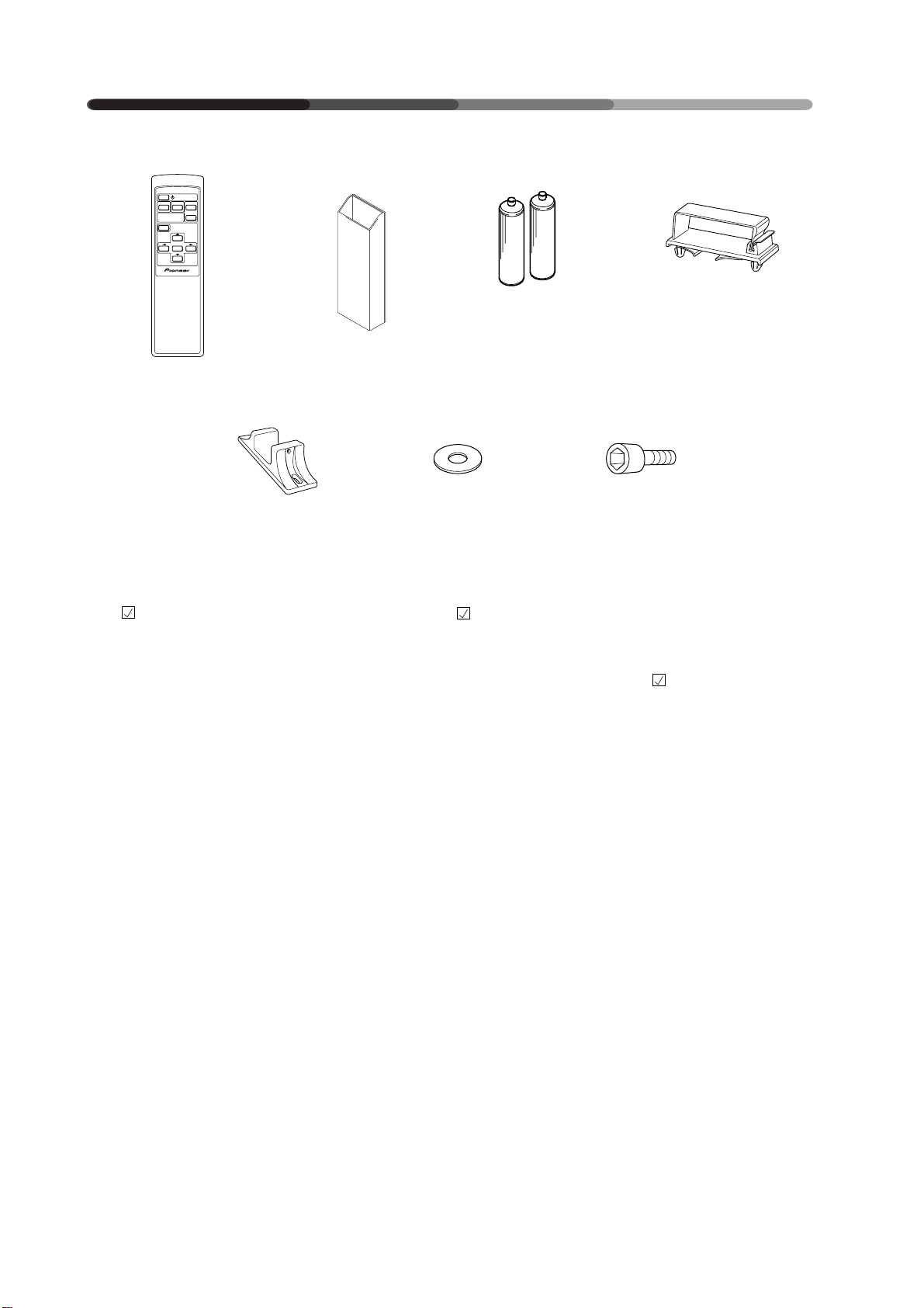
Tick the box of accessories to
confirm they have been properly
provided.
1 Remote control unit
&
2 Remote control case &
3 Two AA batteries &
4 Three cable clamps &
5 Two stands &
6 Two washers &
7 Two bolts &
8 Operating Instructions &
Cocher la case en face des
accessoires afin de confirmer que
ceux-ci sont bien présents.
1 Télécommande
&
2 Boîtier de télécommande &
3 Deux piles AA &
4 Trois serre-câbles &
5 Deux supports &
6 Deux rondelles &
7 Deux boulons &
8 Notice d’utilisation &
Zur Überprüfung, ob alle
angegebenen Zubehörteile
ordnungsgemäß geliefert wurden,
kreuzen Sie jeweils das betreffende
Kästchen
1 Fernbedienung
an.
&
2 Fernbedienungsgehäuse &
3 Zwei AA-Batterien &
4 3 Kabelklemmen &
5 2 Sockel &
6 2 Unterlegscheiben &
7 2 Schrauben &
8 Bedienungsanleitung &
6
<ARE1348>
En/Fr/Ge
PANEL FEATURES AND FUNCTIONS
CARACTERISTIQUES ET FONCTIONS DES PANNEAUX
TASTEN, EINSTELLUNGEN UND FUNKTIONEN
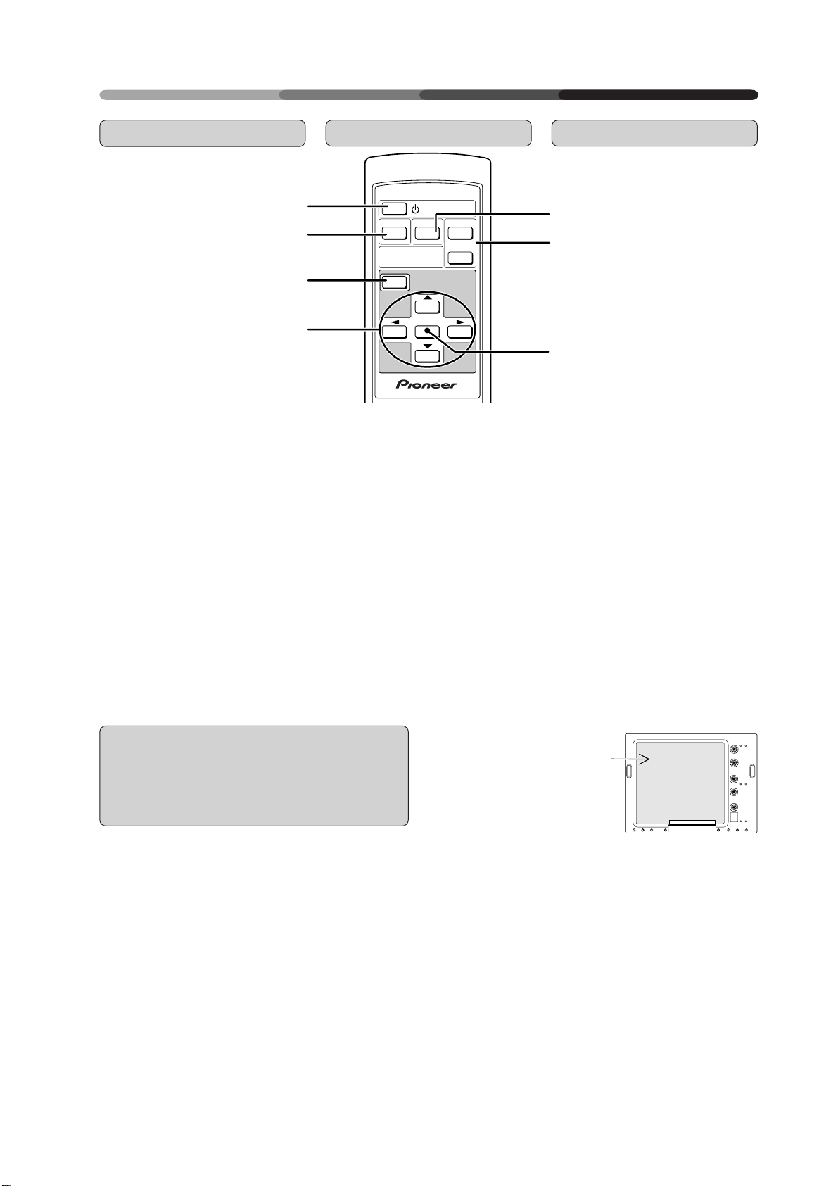
Remote Control Unit
1 STANDBY/ON button:
Turns on/shuts off the power.
2 VIDEO button:
Selects video input as the input
function.
3 MENU button:
Switches between the menu and
ordinary screens.
4 ADJUST button:
Use to adjust the picture quality.
5 Y/C button:
Selects Y/C input as the input function.
6 RGB-1 & 2 buttons:
Select RGB-1 (BNC terminal) and
RGB-2 (MINI D-SUB terminal) respectively as the input functions.
7 SET button:
Use to finalize menu selections
when adjusting picture quality.
Commande à distance
1
2
3
4
1 Bouton STANDBY/ON (= alimenta-
tion) :
Pour la mise sous tension/hors tension
2 Bouton VIDEO :
Sélection de la vidéo comme fonction
d’entrée
3 Bouton MENU :
Commutation entre les écrans de
menu et les écrans ordinaires
4 Bouton ADJUST (= réglage) :
Réglage de la qualité de l’image
5 Bouton Y/C :
Sélection de Y/C comme fonction
d’entrée
6 Boutons RGB-1 & 2 :
Sélection de RGB-1 (borne BNC) et de
RGB-2 (borne MINI D-SUB) en tant que
fonction d’entrée
7 Bouton SET (= sélection) :
Finalisation des sélections de menu
lors du réglage de la qualité de l’image
VIDEO Y/C
INPUT
SELECT
MENU
SET
STANDBY/ON
RGB 1
RGB 2
Î
Fernbedienung
5
6
7
1 STANDBY/ON-Taste :
Schaltet die Netzspannung ein/aus.
2 VIDEO-Taste :
Aktiviert den Video-Eingang.
3 MENU-Taste :
Schaltet die Menüoberfläche ein
und aus.
4 ADJUST-Taste :
Funktionstasten, um die
Einstellungen vorzunehmen.
5 Y/C-Taste :
Aktiviert den Y/C-Eingang.
6 RGB-1 & 2-Tasten :
Aktiviert RGB Eingang 1 (BNCRGBS) und RGB Eingang 2 (D-SUB).
7 SET-Taste :
Aktiviert und bestätigt die
Einstellungen.
Remote Control Case Installation
Installation du boîtier de la commande
à distance
Anbringen des Fernbedienungshalters
A remote control case is supplied to prevent loss of
the remote control. If you are going to use the remote control case, attach it to the face shown at the
right. Clean off any dirt from the installation location
before attaching the remote control case.
Un boîtier est fourni afin d’empêcher la perte de la
commande à distance. Si vous comptez utiliser le
boîtier de la commande à distance, fixez-le sur le côté
illustré à droite. Nettoyez avec soin l’endroit où vous
allez installer le boîtier de la commande à distance
avant de l’y fixer.
Der beiliegende Fernbedienungshalter sorgt dafür,
daß die Fernbedienung stets am korrekten Platz
abgelegt wird. Falls eine Verwendung des
Fernbedienungshalters gewünscht wird, sollte er an
der rechts gezeigten Fläche befestigt werden. Vor
dem Anbringen des Halters die Anbringungsfläche
von Staub und Schmutz befreien.
• Attach the remote control case to
this surface
• Fixer le boîtier de al commande à
distance à cet endroit
• Bringen Sie den
Fernbedienungshalter an dieser
Stelle an.
• Note that the plasma display installation method may prevent attachment of the remote control case in some cases.
• Attaching the remote control case to another face may
block the vents and cause damage, so be sure to attach
the remote control case to the specified face only.
• Notez que la procédure d’installation d’un écran à plasma
peut parfois empêcher la fixation du boîtier de la
commande à distance.
• Fixer le boîtier de la commande à distance sur un autre
côté peut entraver la ventilation et endommager le
matériel. Assurez-vous de bien fixer le boîtier à l’endroit
prévu à cet effet.
• Bei gewissen Installationen des Plasma-Monitors läßt
sich der Fernbedienungshalter unter Umständen nicht
anbringen.
• Falls der Fernbedienungshalter an einer anderen Fläche
angebracht wird, beeinträchtigt er möglicherweise die
Belüftung, was Schäden zur Folge hat. Den Halter nur an
der angewiesenen Fläche anbringen.
7
<ARE1348>
En/Fr/Du
PANEL FEATURES AND FUNCTIONS
CARACTERISTIQUES ET FONCTIONS DES PANNEAUX
TASTEN, EINSTELLUNGEN UND FUNKTIONEN
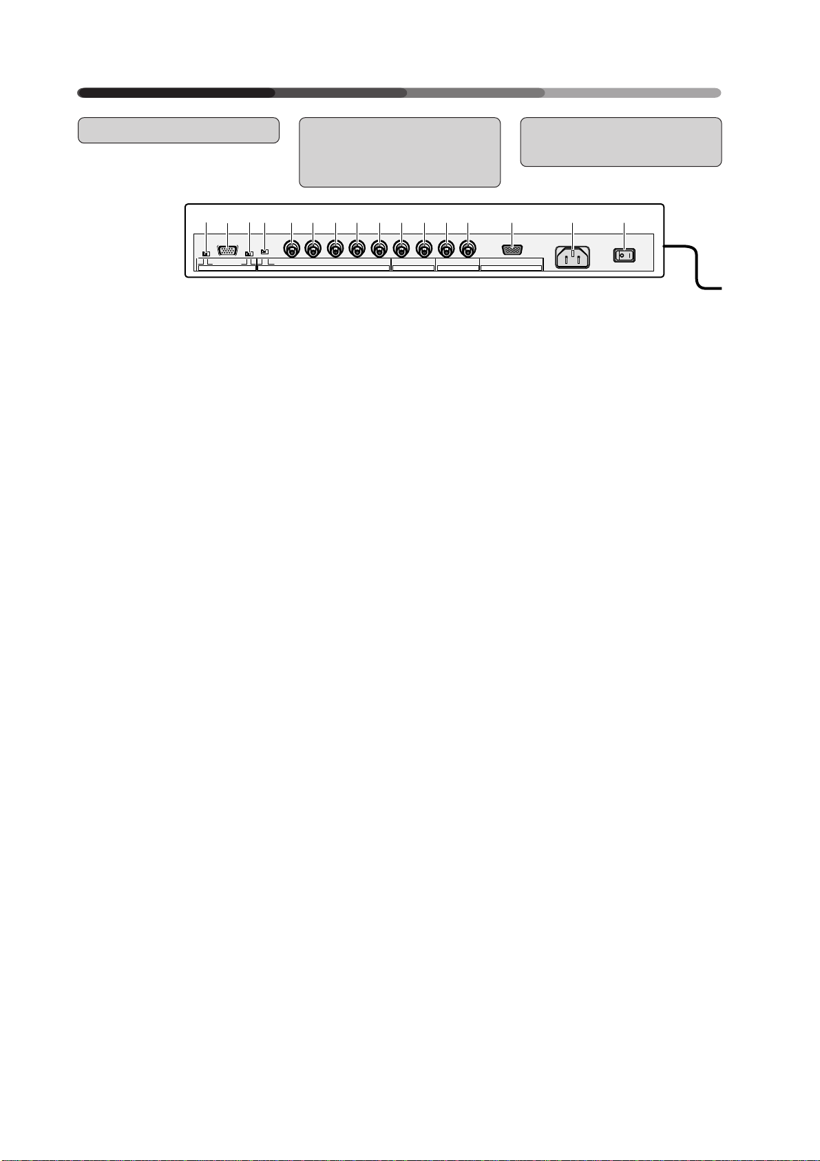
Control and Rear Panels
97
8
(Ω)
OFF ON
<Rear Panel Terminal/Connections to Power Source>
<Bornes du panneau arrière/Connexions à la source d’alimentation>
<Hintere Anschlußleiste / Netzanschluß>
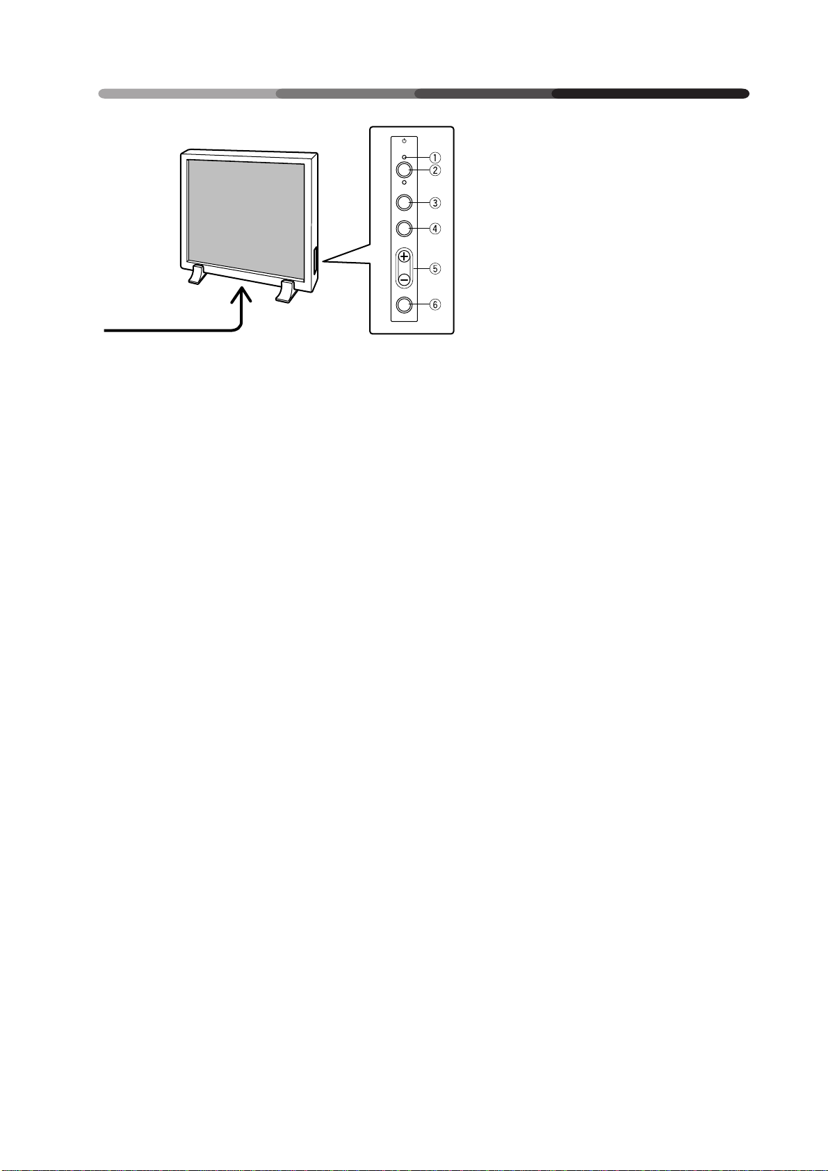
<Control Panel>
1 STANDBY/ON indicator
The indicator is red when in
standby mode and turns green
when the power to the display
is turned on.
2 STANDBY/ON button
Press to turn the power to the
display on and off.
3 INPUT button
Press to switch the various input functions.
4 MENU button
Press to enter the menu screen
and exit from it.
5 ADJUST button
Use the +/– buttons to adjust picture quality.
6 SET button
Press to finalize menu selections
when adjusting picture quality.
<Rear Panel Terminals/Connections to Power Source>
RGB-2 input terminals
7 Remote control out switch
(ON/OFF)
This switch will output remote
control commands from the
RGB-2 (D-SUB 15-pin) terminal
to control external peripheral
devices planned for future
sales release. Normally be
sure to use set to OFF.
8 MINI D-SUB 15-pin terminal
9 G on Sync mode selection
switch (ON/OFF)
If the images become greenish
when an external device is
connected to the RGB-2 input
terminal, turn ON the G on
SYNC mode. Normally set to
OFF.
8
<ARE1348>
En/Fr/Ge
75 2.2kOFF ON
SYNCREMOTE G ON SYNC
Panneau de commande et panneau
Anschlüsse und
Bedienungstasten
arrière
-0=~!@#$%^ & (*
VD HD B G R C Y OUT IN
(H/V SYNC) RGB-1 (ON SYNC) Y/C
<Panneau de commande>
1 Témoin STANDBY/ON (= en at-
tente/marche)
Ce témoin est rouge lorsqu’il est
dans le mode en attente et
devient vert lorsque l’écran est
mis sous tension.
2 Bouton STANDBY/ON (= Ali-
mentation)
Appuyer sur ce bouton pour
mettre l’écran sous tension et
hors tension
3 Bouton INPUT (= entrée)
Appuyer sur ce bouton pour la
commande des différentes
fonctions d’entrée
4 Bouton MENU
Appuyer sur ce bouton pour
entrer dans l’écran menu et en
sortir.
5 Bouton ADJUST (= réglage)
Utiliser les boutons +/- pour
ajuster la qualité de l’image
6 Bouton SET (= sélection)
Appuyer sur ce bouton pour
finaliser les sélections de menu lors
du réglage de la qualité de l’image.
<Bornes du panneau arrière/
Connexions à la source
d’alimentation>
Bornes d’entrée RGB-2
7 Contacteur d’émission de
commandes à distance (ON/
OFF = MARCHE/ARRET)
Ce contacteur émet les
commandes à distance en provenance de la borne RGB-2 (DSUB 15 broches) vers les
périphériques externes qui
seront vendus à l’avenir.
S’assurer que le réglage est sur
OFF.
8 Borne 15 broches MINI D-SUB
9 G sur bouton de sélection du
mode Sync (ON/OFF =
MARCHE/ARRET)
Si les images deviennent verdâtres lorsqu’un dispositif extérieur est raccordé au terminal
d’entrée RGB-2, amener G sur le
mode SYNC. Normalement, celui-ci est réglé sur OFF (= arrêt).
VIDEO RS-232CRGB-2
<Bedienungstasten>
1 STANDBY/ON-Leuchtdiode
Die Leuchtdiode leuchtet rot auf,
wenn die
Bereitsschaftsschaltung an ist,
und wechselt zu grün, wenn das
Display eingeschaltet ist.
2 POWER-Taste
Mit dieser Taste wird das Gerät
ein- und ausgeschaltet.
3 INPUT-Taste
Mit dieser Taste werden die
Eingänge umgeschaltet.
4 MENU-Taste
Mit dieser Taste wird die
Menüoberfläche aktiviert.
5 ADJUST-Taste
Mit den +/– Tasten werden die
Einstellungen vorgenommen.
6 SET-Taste
Mit dieser Taste werden die
Einstellungen aktiviert und
bestätigt.
<Anschlußleiste>
RGB 2-Eingang
7 EIN-/AUS-Schalter der Fernbe-
dienung (ON/OFF)
Mit diesem Schalter können
Fernbedienungsbefehle über
den Anschluß RGB-2 (D-SUB,
15-Pin-Buchse) ausgegeben
werden, um zukünftiges
Zubehör zu steuern.
Für den Normalbetrieb
unbedingt auf OFF stellen.
8 MINI D-SUB 15-Pin-Eingang
9 G an Sync-Moduswählschalter
(ON/OFF)
Wird der Bildschirm grünlich,
sobald ein externes Gerät an
der Input-Schnittstelle von
RGB - 2 - angeschlossen
wird, schalten Sie G am
Sync-Moduswählschalter
auf ON (EIN), während es
normalerweise auf OFF (AUS)
steht.
CARACTERISTIQUES ET FONCTIONS DES PANNEAUX
TASTEN, EINSTELLUNGEN UND FUNKTIONEN
STANDBY
/ON
INPUT
MENU
ADJUST
SET
<Control Panel>
<Panneau de commande>
<Seitliche Tasten>
PANEL FEATURES AND FUNCTIONS
RGB-1 input terminals
0 Sync Signal Input Impedance
switch (75 Ω/2,2 kΩ)
- Vertical Sync Signal Input ter-
minal: (75 Ω/2,2 kΩ, switchable with the Sync Signal Input Impedance switch)
= Horizontal or Composite Sync
Signal Input terminal: (75 Ω/
2,2 kΩ, switchable with the
Sync Signal Input Impedance
switch)
~ Blue Signal Input terminal:
75 Ω
! Green or Green with Sync Sig-
nal Input terminal (ON SYNC)
:75 Ω
@ Red Signal Input terminal: 75 Ω
Y/C input terminals
# Color Signal Input terminal:
75 Ω
Bornes d’entrée RGB-1
0 Commutateur d’impédance
d’entrée du signal de synchronisation (75 Ω/2,2 kΩ)
- Borne d’entrée du signal de
synchronisation vertical (75 Ω/
2,2 kΩ, commutable avec le
commutateur d’impédance
d’entrée du signal de synchronisation)
= Borne d’entrée du signal de
synchronisation horizontal ou
composite : (75 Ω/2,2 kΩ, commutable avec l’interrupteur
d’impédance d’entrée du signal de synchronisation)
~ Borne d’entrée du signal bleu
: 75 Ω
! Borne d’entrée du signal vert
ou vert avec signal de synchronisation (ON SYNC) : 75 Ω.
@ Borne d’entrée du signal rouge
: 75 Ω
RGB 1-Eingang
0 Synchronsignal-Eingangs-Im-
pedanz-Schalter (75 Ω/2,2 kΩ).
- Vertikaler Synchronsignal-Einga-
ng (75 Ω/2,2 kΩ, einstellbar mit
dem Synchronsignal-EingangsImpedanz-Schalter).
= Horizontaler oder kombiniert-
er Synchroneingang: (75 Ω/2,2
kΩ, einstellbar mit dem Synchronsignal-Eingangs-Impedanz-Schalter).
~ Blaues Signal: 75 Ω
! Grünes Signal oder Grün mit
Synchronsignal-Eingang (ON
SYNC): 75 Ω
@ Rotes Signal: 75 Ω
Y/C Eingang
# Farbsignal Eingang: 75 Ω
$ Helligkeitssignal-Eingang: 75 Ω
$ Luminance Signal Input termi-
nal: 75 Ω
VIDEO input/output terminals
% Video Output terminal: 75 Ω
^ Video Input terminal: 75 Ω
& Control Signal Input terminal
(RS-232C)
* AC inlet
( MAIN POWER switch
Bornes d’entrée Y/C
# Borne d’entrée du signal
couleur : 75 Ω
$ Borne d’entrée du signal de
luminance : 75 Ω
Bornes d’entrée/sortie VIDEO
% Borne de sortie vidéo : 75 Ω
^ Borne d’entrée vidéo : 75 Ω
& Borne d’entrée du signal de
commande (RS-232C)
* Prise c.a.
( Interrupteur général POWER
VIDEO-Eingang/Ausgang
% Video-Ausgang: 75 Ω
^ Video-Eingang: 75 Ω
& Kontrollsignal-Eingang (RS-
232C)
* Netzanschluß
( Netzschalter (MAIN POWER)
9
<ARE1348>
En/Fr/Du
PANEL FEATURES AND FUNCTIONS
CARACTERISTIQUES ET FONCTIONS DES PANNEAUX
TASTEN, EINSTELLUNGEN UND FUNKTIONEN
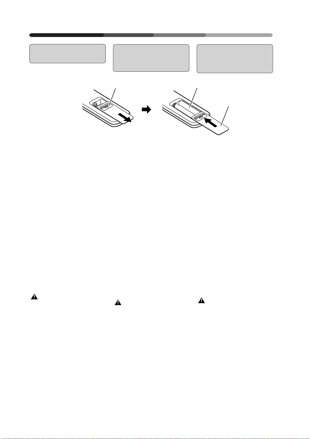
Putting Batteries in the
Remote Control Unit
1 To add or change the batteries,
slide the cover of the battery
compartment on the back of the
remote control unit towards you
while pushing down on it.
2 Replace or add two AA batter-
ies.
3 Close the cover of the battery
case.
How to care for the remote control
unit:
• Do not drop the remote control
unit.
• Do not get the remote control unit
wet.
• Do not use or store the remote
control unit in the following locations:
In a place subject to direct sunlight
In a place subject to heat radiated by a heating system
In a humid place
CAUTION
• Never mix new and used batteries.
• Do not use different brands of
batteries. Batteries of the same
size may have different voltage.
• When the unit will not be used for
a long time (more than one
month), remove the batteries to
prevent liquid leakage occurs,
wipe up the liquid from the case
and replace the batteries with
new ones.
• Do not charge, short-circuit, break
down or expose the batteries provided with the display to flames.
10
<ARE1348>
En/Fr/Ge
Installation des piles
dans la commande à
distance
Batterien in die
Fernbedienung
einlegen
12
9
(
1 Pour ajouter ou remplacer des
piles, faire coulisser le couvercle
du compartiment à piles qui se
trouve au dos de la commande
à distance vers soi tout en poussant vers le bas.
2 Remplacement ou mise en place
de deux piles AA
3 Refermer le couvercle du com-
partiment a piles.
Précautions à prendre pour la commande à distance :
• Ne pas laisser tomber la commande à distance
• Protéger la commande à distance
contre l'humidité
• Ne pas utiliser ni ranger la commande à distance :
dans un endroit soumis au rayonnement solaire direct
dans un endroit soumis à la
chaleur irradiée par un système
de chauffage
dans un endroit humide.
ATTENTION
• Ne jamais mélanger des piles
neuves et usagées.
• Ne pas utiliser des marques de
piles différentes. Des piles de
même dimension peuvent avoir
des tensions différentes.
• Si l'unité doit rester inactive pendant une durée prolongée (plus
d'un mois), enlever les piles afin
de prévenir les fuites de liquide à
l'intérieur du compartiment à
piles. En cas de fuite, essuyer le
liquide qui s'écoule du compartiment et remplacer les piles anciennes par des piles neuves.
• Ne pas charger, court-circuiter,
provoquer la défaillance des piles
fournies avec l'écran ni les exposer à la flamme.
(
9
1 Um Batterien einzulegen oder
auszuwechseln, schieben Sie
die Abdeckplatte des
Batteriefaches auf der Rückseite
der Fernbedienung in Ihre
Richtung während Sie sie
gleichzeitig eindrücken.
2 Legen Sie zwei AA-Batterien ein.
3 Schließen Sie den
Batteriefachdeckel.
Umgang mit der Fernbedienung:
• Lassen Sie die Fernbedienung
nicht fallen.
• Lassen Sie die Fernbedienung
nicht naß werden.
• Benutzen Sie oder lagern Sie die
Fernbedienung nicht an den
nachstehenden Orten:
An Orten, die der direkten
Sonneneinstrahlung ausgesetzt
sind.
An Orten, die der
Wärmeeinstrahlung durch
Heizkörper ausgesetzt sind.
An feuchten Orten.
Vorsicht
• Benutzen Sie niemals gebrauchte
und neue Batterien gleichzeitig.
• Benutzen Sie keine Batterien
verschiedener Marken. Batterien
gleicher Größe können
unterschiedliche Spannung haben.
• Wenn das Gerät über längere Zeit
nicht benutzt wird (länger als einen
Monat), sollten Sie die Batterien
herausnehmen, um ein Auslaufen
zu vermeiden. Läuft die Batterie
dennoch aus, wischen Sie die
Flüssigkeit vorsichtig (Säure!) ab
und ersetzen die Batterien durch
neue.
• Die mit dem Display gelieferten
Batterien dürfen nicht aufgeladen,
kurzgeschlossen,
auseinandergenommen oder
offener Flamme ausgesetzt werden.
3
PANEL FEATURES AND FUNCTIONS
CARACTERISTIQUES ET FONCTIONS DES PANNEAUX
TASTEN, EINSTELLUNGEN UND FUNKTIONEN
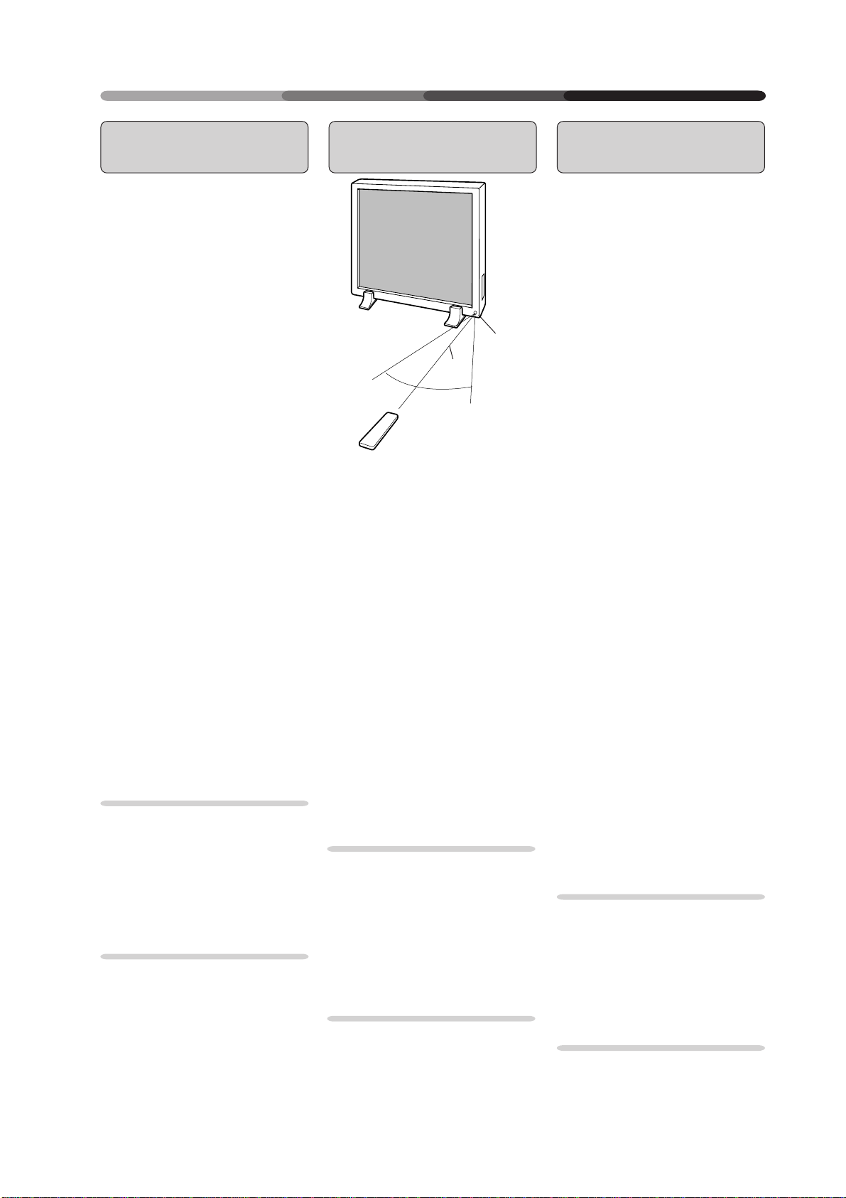
Remote Control Operation Range
• If there is an obstacle between the
remote control unit and the display, the unit may not operate
with the remote control unit.
In this case, move the obstacle or
change your position.
• As the battery power is weakens,
the remote control operation
range becomes shorter. If the operation range becomes too short,
replace the batteries.
NOTES:
The Plasma Display discharges
weak infrared rays from the screen.
When devices operated by infrared
remote control units such as VCRs
are installed near the Plasma
Display, it may be difficult for the
devices to receive signals from the
remote control unit, or they may not
be able to receive the signals at all.
Depending on the installation
environment, the Plasma Display
may not be able to receive signals
from the remote control unit or the
operating distance of the remote
control unit may shorten due to
effects of the infrared rays
discharged from the Plasma
Display.
The intensity of the infrared rays
discharged from the screen
changes according to the image
displayed.
Portée de la commande à distance
Remote sensor
7 m
30 °
• Si un obstacle est présent entre la
commande à distance et l'écran,
l'unité peut ne pas fonctionner
avec la commande à distance.
Dans ce cas, déplacer l'obstacle ou
changer de position.
• Au fur et à mesure de l'épuisement
de la pile, la portée de la commande à distance se réduit. Lorsque cette portée devient trop
faible, remplacer les piles.
30 °
REMARQUES :
L’écran à plasma émet des rayons
infrarouges de faible intensité.
Lorsque des dispositifs
commandés par des commandes à
distance par infrarouge, comme
des VCR, sont installés à proximité
de l’écran à plasma, il peut être
difficile pour les dispositifs de
recevoir des signaux depuis la
commande à distance. Il arrive
parfois aussi qu’ils ne reçoivent
aucun signal.
En fonction de l’environnement
d’installation, il est possible que
l’écran à plasma ne soit pas en
mesure de recevoir des signaux de
la commande à distance ou bien
que la distance de fonctionnement
de la commande à distance soit
raccourcie en raison des effets des
rayons infrarouges émis par l’écran
à plasma.
L’intensité des rayons infrarouges
émis par l’écran varie en fonction
de l’image affichée.
Capteur de télédétection
Sensorfenster
Empfangsbereich der
Fernbedienung
• Wenn sich zwischen der
Fernbedienung und dem Display
ein Hindernis befindet, kann es
sein, daß das Gerät nicht mit der
Fernbedienung betrieben werden
kann. In diesem Fall entfernen Sie
das Hindernis oder wechseln Sie
Ihre Position.
• Wenn die Batteriespannung
nachläßt, verringert sich der
Empfangsbereich der
Fernbedienung. Wenn der
Empfangsbereich zu klein wird,
müssen die Batterien ersetzt
werden.
Anmerkung :
Das Plasma-Display sendet
schwache Infrarotstrahlen aus.
Wenn sich in der Nähe des PlasmaDisplays Geräte oder Vorrichtungen
befinden, die durch
Infrarotfernsteuerungen betrieben
werden, wie beispielsweise VCRs,
kann es sich für die Geräte als
schwierig oder gar unmöglich
erweisen, Signale von der
Fernsteuerung zu empfangen.
Je nach Installationsumgebung
kann das Plasma-Display eventuell
nicht in der Lage sein, Signale von
der Fernsteuerung zu empfangen,
oder aber der Betriebsabstand der
Fernsteuerung verkürzt sich
aufgrund der Wirkung der vom
Plasma-Display ausgesandten
Infrarotstrahlen.
Die Intensität der vom Schirm
ausgesandten Infrarotstrahlen
schwankt je nach angezeigtem Bild.
11
<ARE1348>
En/Fr/Du
VIEWING IMAGES ON YOUR PLASMA DISPLAY
VIDEO Y/C
RGB 2 RGB 1
VISUALISATION DES IMAGES SUR L’ECRAN A PLASMA
BILDWIEDERGABE AUF IHREM PLASMA-DISPLAY
OUT IN
VIDEO RS-232C
INPUT
SELECT
MENU
VIDEO
STANDBY
/ON
INPUT
MENU
ADJUST
SET
STANDBY/ON
Y/C
RGB 2
STANDBY
/ON
RGB 1
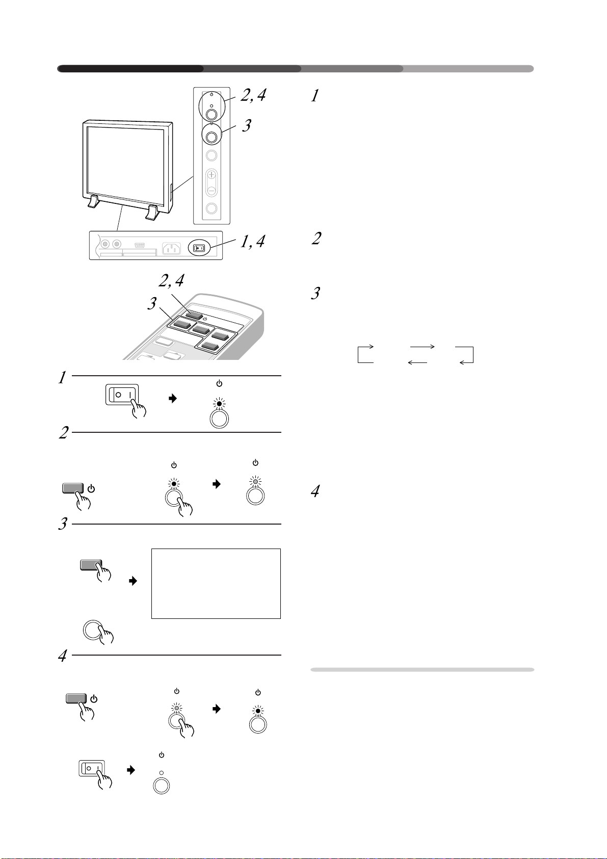
Input the power to the main unit.
The standby indicator will flash in red for about 4
seconds. The display then enters standby state and
the indicator remains lit.
NOTE :
The buttons on the main unit and remote control unit,
and the external control commands are not accepted
by the display unit while the standby indicator is flashing in red.
Turn on the Display.
The STANDBY indicator turns green.
Select an input source.
• Press the INPUT switching button on the main unit
: each time press changes the input source as follows:
• To choose an input source with the remote control, press the INPUT SELECT button.
• The function cannot be switched at the MENU
screen.
Remote control
Commande à distance
Fernbedienung
STANDBY/ON
Remote control
Commande à distance
Fernbedienung
VIDEO
Main unit
Unité principale
Hauptgerät
INPUT
Remote control
1
Commande à distance
Fernbedienung
STANDBY/ON
Main unit
Unité principale
Hauptgerät
STANDBY
/ON
Main unit
Unité principale
Hauptgerät
STANDBY
/ON
STANDBY
/ON
V I DEO
STANDBY
/ON
“NO SYNC!” is displayed if no signal is being input .
“OUT OF RANGE!” is displayed if the signal being
input cannot be processed on this set.
After use, turn off the power.
1 Turn off the power.
The standby indicator flashes in red for about 4 seconds, then remains lit (standby state).
2 Turn off the MAIN POWER switch on the main
unit.
The STANDBY/ON indicator will dim and the power
to the unit will be turned off.
NOTE :
The buttons on the main unit and remote control unit,
and the external control commands are not accepted
by the display while the standby indicator is flashing
in red.
Do not display the same image (still images, etc.) for
a long time as the image may stick onto the screen.
2
12
<ARE1348>
En/Fr/Ge
STANDBY
/ON
VIEWING IMAGES ON YOUR PLASMA DISPLAY
VIDEO Y/C
RGB 2 RGB 1
VISUALISATION DES IMAGES SUR L’ECRAN A PLASMA
BILDWIEDERGABE AUF IHREM PLASMA-DISPLAY
Alimentation de l’écran en énergie
Le témoin en attente rouge clignote pendant 4
secondes environ. Ensuite, l’écran passe en mode
attente et ce témoin reste allumé.
NOTE :
Les boutons de l’unité principale et de la commande
à distance, ainsi que les instructions de commande
extérieures ne sont pas acceptés par l’écran tant que
le témoin en attente rouge clignote.
Allumage de l’écran
Le témoin STANDBY (en attente) devient vert.
Sélection d’une source d’entrée
• Pousser sur le bouton de commutation INPUT
(entrée) de l’unité principale : chaque pression
modifie la source d’entrée comme suit :
VIDEO Y/C
RGB 2 RGB 1
• Pour sélectionner une source d’entrée avec la
commande à distance, appuyer sur le bouton INPUT SELECT (= sélection d’entrée)
• La fonction ne peut pas être commutée à l’écran
MENU.
Schalten Sie den Hauptschalter ein.
Die Bereitschafts-Leuchtdiode blinkt etwa 4 Sekunden
lang rot. Dann wechselt das Gerät in den
Bereitschaftszustand, und die BereitschaftsLeuchtdiode leuchtet.
Anmerkung:
Solange die Bereitschafts-LED rot blinkt, reagiert das
Display weder auf die Tasten des Hauptgerätes oder
der Fernbedienung, noch auf externe Befehle.
Schalten Sie das Display ein.
Die Bereitschafts-LED wird grün.
Wählen Sie die Eingangsquelle.
• Drücken Sie die Eingangstaste am Hauptgerät: bei
jedem Tastendruck wechselt die Eingangsquelle
wie folgt:
• Wenn Sie per Fernbedienung eine Eingangsquelle
wählen möchten, drücken Sie bitte eine SELECTTaste.
• Diese Funktion kann nicht mit der MENUOberfläche eingestellt werden.
«NO SYNC !» s’affiche en l’absence de réception d’un
signal à la sélection de RGB-1 ou de RGB-2.
«OUT OF RANGE» s’affiche si le signal reçu ne peut
pas être traité par cet appareil.
Après utilisation, mettre hors tension
1 Mise hors tension
Le témoin en attente rouge clignote pendant environ
4 secondes, puis reste allumé (état en attente).
2 Eteindre l’interrupteur MAIN POWER (= sur l’unité
principale
Le témoin STANDBY/ON diminue d’intensité et
l’alimentation de l’unité est coupé.
NOTE :
Les boutons de l’unité principale et de la commande
à distance, ainsi que les instructions de commande
extérieures ne sont pas acceptées par l’écran tant que
le témoin en attente rouge continue à clignoter.
Ne pas afficher la même image (images immobiles,
etc.) pendant une durée prolongée étant donné que
l’image peut alors rester collée à l’écran.
Falls bei Wahl von RGB-1 oder RGB-2 kein Signal
anliegt, wird „NO SYNC!“ angezeigt.
Falls ein Signal anliegt, das nicht verarbeitet werden
kann, erscheint „OUT OF RANGE“.
Nach dem Gebrauch schalten Sie
den Netzschalter aus.
1 Schalten Sie den Strom aus.
Die Bereitschafts-LED blinkt etwa 4 Sekunden lang
rot, und leuchtet dann kontinuierlich
(Bereitschaftsstatus).
2 Schalten Sie den Netzschalter am Hauptgerät
aus.
Die Bereitschafts-LED erlischt, und die Stromzufuhr
zum Gerät ist ausgeschaltet.
Anmerkung:
Solange die Bereitschafts-LED rot blinkt, reagiert das
Display weder auf die Tasten des Hauptgerätes oder
der Fernbedienung, noch auf externe Befehle.
Zeigen Sie nicht dasselbe Bild (stillstehende Bilder
usw.) über einen längeren Zeitraum an, da dieses auf
dem Schirm “festkleben“ kann.
13
<ARE1348>
En/Fr/Ge
HOW TO ADJUST PICTURE QUALITY
COMMENT REGLER LA QUALITE DE L’IMAGE
EINSTELLEN DER BILDQUALITÄT
STANDBY
/ON
RGB-1 (BNC) or RGB-2 (MINI D-
Remote control
Commande à distance
Fernbedienung
MENU
Main unit
Unité principale
Hauptgerät
MENU
Remote control
Commande à distance
Fernbedienung
Main unit
Unité principale
Hauptgerät
ADJUST
Remote control
Commande à distance
Fernbedienung
SET
Main unit
Unité principale
Hauptgerät
SET
14
<ARE1348>
En/Fr/Ge
INPUT
MENU
ADJUST
SET
VIDEO
STANDBY/ON
Y/C
INPUT
SELECT
MENU
SET
RGB 1
RGB 2
P I CTURE PARAMETER
CONTRAST
I
GHT.
BR
CLK. FRQ.
CLK. PHS.
HOR. POS.
VER. POS.
I N I
T.
SCART RGB
SET : SEL. MENU : EXIT
• Displayed only for RGB-1.
• S’affiche uniquement pour le
RGB-1
• Anzeige nur für RGB-1
P I CTURE PARAMETER
CONTRAST
I
GHT.
BR
CLK. FRQ.
CLK. PHS.
HOR. POS.
VER. POS.
I N I
T.
SCART RGB
SET : SEL. MENU : EXIT
• Displayed only for RGB-1.
• S’affiche uniquement pour le
RGB-1
• Anzeige nur für RGB-1
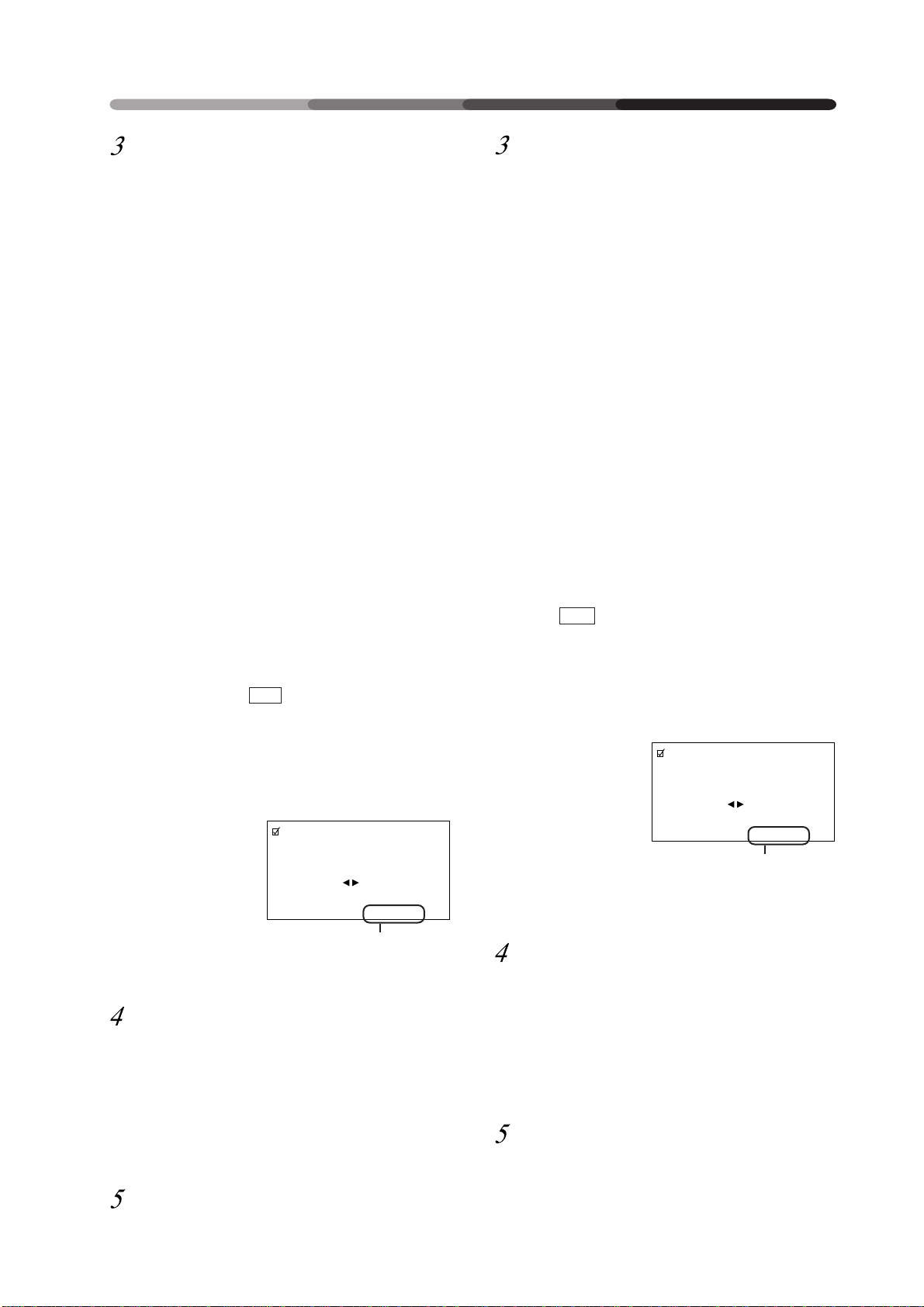
• The currently selected item
will be displayed in purple.
• L’option sélectionnée apparaît
en pourpre.
• Das gewählte Item wird
purpurfarbig wiedergegeben.
P I CTURE PARAMETER
CONTRAST
: ADJ. SET : EXIT
+ 1 0
– 5
+ 8
OFF
+ 1 0
– 5
+ 8
OFF
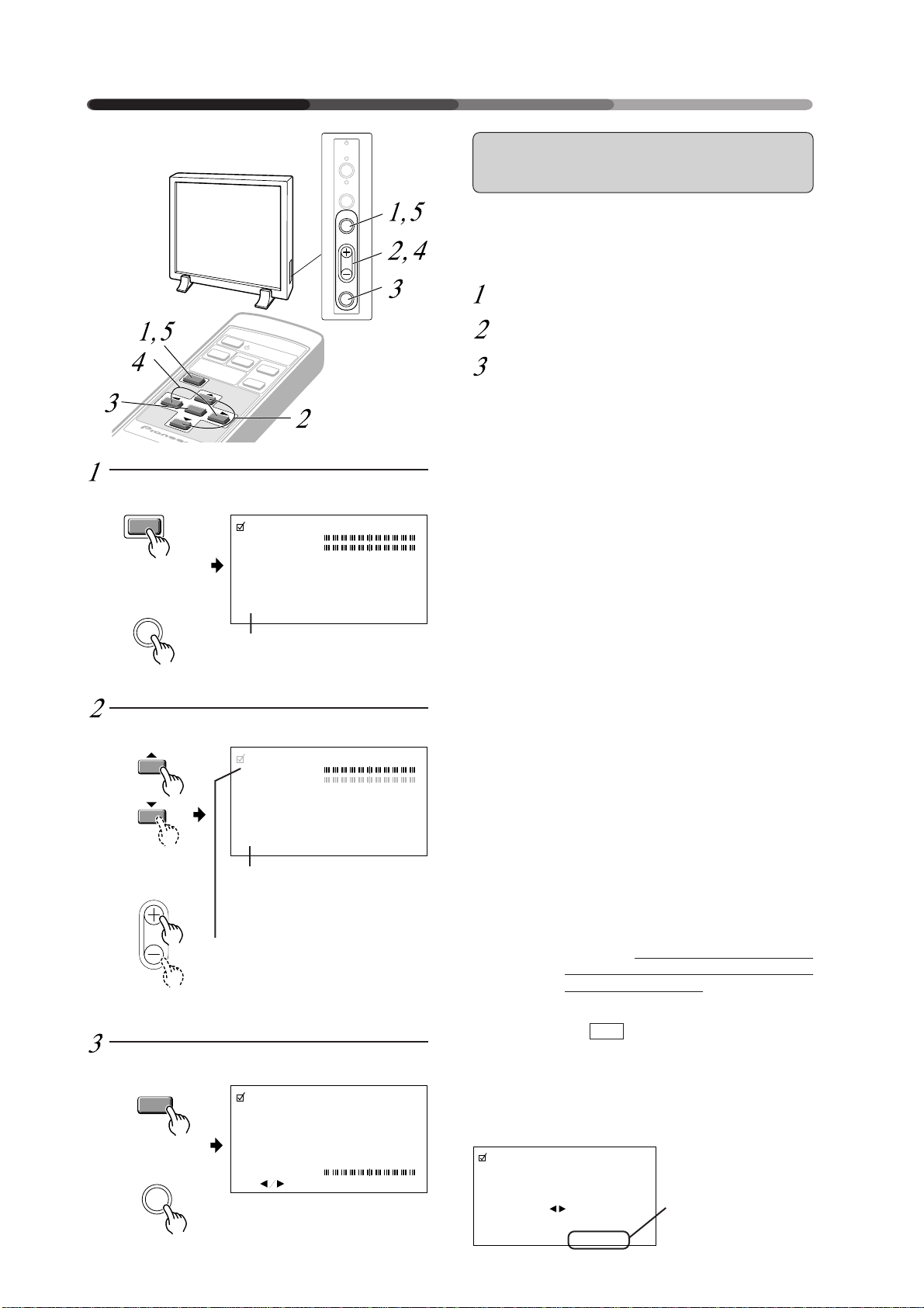
SUB) Input:
Adjust the picture quality for each input: the RGB-1
(BNC), the RGB-2 (MINI D-SUB), the video, and the Y/C.
* Refer to page 51 for the sources.
Switch to the MENU screen.
Choose the item to be adjusted.
Finalize your choice.
Make adjustment concerning each item as follows:
CONTRAST .. Adjusts the contrast of the picture ac-
cording to the brightness of the environment so that you can watch the
picture easier.
BRIGHT......... Adjusts the brightness of the picture
so that you can watch the darker parts
of the picture easier.
CLK.FRQ. ...... When part of the letters in the picture
is missing, or if the displayed image
0
(–32 to +32)
CLK.PHS. ...... When some letters in the picture
(–128 to +127)
0
HOR.POS. ..... Adjust the horizontal position of the
(–32 to +32)
VER.POS....... Adjust the vertical position of the pic-
(–32 to +32)
INIT. .............. Returns the above picture settings to
SCART RGB ...
(ON/OFF)
(Displayed
only for RGB-1)
*1
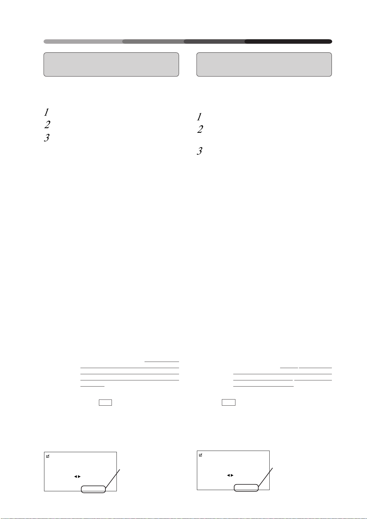
When you select INIT. , the message on the right is
displayed. Select “YES” or “NO” by using the 2 or
3 button.
Selecting “YES” and pressing the SET button sets back
all picture quality settings to their default values.
When “NO” is selected, all settings will remain as
they are.
P I CTURE PARAMETER
is distorted as a rainbow-like noise,
use this function. This function is to
adjust the frequency of the internal
clock signal for the video signal input.
NOTE:
HOR.POS may need to be adjusted in
some cases if CLK.FRQ has been adjusted.
flicker and the color becomes distorted, use this function. Adjust it to
minimize the flicker and the color distortion. This function is to adjust the
phase of the internal clock signal,
which is adjusted with the CLK. FRQ
function.
picture.
ture.
their center values. *1
This switches the synchronizing signal mode.
for RGB input to a unit with a Euro AV
terminal on page 39.
I N I T I AL I ZE?
YES NO
SET : EX
Always leave it OFF, except
If “NO” has been selected, SET:EXIT will
be displayed here.
If “YES” has been selected, SET:INIT will be
I
T
displayed.
HOW TO ADJUST PICTURE QUALITY
COMMENT REGLER LA QUALITE DE L’IMAGE
EINSTELLEN DER BILDQUALITÄT
Entrée RGB-1 (BNC) ou RGB-2
(MINI D-SUB)
Régler la qualité de l’image pour chaque entrée : RGB1 (BNC), RGB-2 (MINI D-SUB), vidéo et Y/C.
* Référez-vous à la page 52 pour les sources.
Passage à l’écran MENU
Sélectionner l’option à régler
Finalisation de la sélection
Opérer les réglages pour chaque option comme suit :
CONTRAST ... Règle le contraste de l’image en fonction
BRIGHT .........Règle la luminosité de l’image de
CLK.FRQ .......Utiliser cette fonction. Si une partie des
(–32 à +32)
CLK.PHS .......Utiliser cette fonction. Lorsque certaines
(–128 à +127)
HOR.POS ...... Régler la position horizontale de
(–32 à +32)
VER.POS ....... Règle la position verticale de l’image.
(–32 à +32)
INIT. ...............Ramène les sélections d’image
SCART RGB .. Cette option active le mode de signal
(ON/OFF)
(s’affiche
uniquement
pour le RGB-1)
de la luminosité de l’environnement de
manière à pouvoir visionner l’image
avec un plus grand confort.
manière à pouvoir visionner les parties
plus sombres de l’image avec un plus
grand confort.
lettres de l’image est absente, ou si
l’image affichée est déformée en tant
que bruit iridescent.
Cette fonction sert à régler la fréquence
du signal d’horloge interne pour
l’entrée du signal vidéo.
NOTE :
HOR.POS devra être réglé dans certains
cas si CLK.FRQ a été réglé.
lettres de l’image scintillent et que la
couleur s’altère.
Régler pour minimiser le scintillement
et la distorsion des couleurs. Cette
fonction a pour but de régler la phase
du signal d’horloge interne qui est
réglée avec la fonction CLK.FRQ.
l’image projetée
supérieures à leurs valeurs centrales. *1
de synchronisation.
toujours le laisser sur OFF sauf pour
une entrée RGB dans une unité
disposant d’un terminal Euro AV (voir
page 39).
Vous devez
RGB-1 (BNC) oder RGB-2 (MINI DSUB) Eingang
Für jeden Eingang sollte die Bildqualität eingestellt werden: für RGB-1 (BNC), RGB-2 (D-SUB), Video und Y/C.
* Die verschiedenen Quellen finden Sie auf Seite 53
dieser Bedienungsanleitung.
Wechseln Sie zur MENU-Oberfläche.
Wählen Sie die Funktion, die Sie
einstellen möchten.
Bestätigen Sie Ihre Wahl.
Jede einzelne Funktion beinhaltet die nachstehenden
Einstellmöglichkeiten:
CONTRAST ... Regelt den Bildkontrast gemäß der Hel-
BRIGHT ......... Regelt die Helligkeit des Bildes, zur besser-
CLK-FRQ ........Wenn ein Teil der Buchstaben im Bild fe-
(–32 bis +32)
CLK.PHS ........ Wenn manche Buchstaben im Bild flim-
(–128 bis +127)
HOR.POS .......Regelt die waagerechte Bildposition.
(–32 bis +32)
VER.POS ........ Regelt die senkrechte Bildposition.
(–32 bis +32)
INIT. ...............Setzt die obengenannten Bildeinstellun-
SCART RGB .. Zum Umschalten des Signalmodus zur
(ON/OFF)
(Anzeige nur
für RGB-1)
ligkeit der Umgebung, zur besseren
Bilderkennung.
en Erkennung der dunklen Bildstellen.
hlt oder die dargestellte Abbildung als regenbogenartiges und rauschendes Bild
wiedergegeben wird, können Sie diese
Funktion benutzen, um die Frequenz des
internen Taktsignals für den VideosignalEingang einzustellen.
Anmerkung:
Nach einer Änderung von CLK.FRQ muß
in manchen Fällen HOR.POS neu eingestellt werden.
mern und die Farben gestört sind, können Sie diese Funktion benutzen. Stellen
Sie sie so ein, daß Flimmern und Farbstörung so weit wie möglich reduziert
werden. Mit dieser Funktion stellen Sie die
Phase des internen Taktsignals, das mit
der CLK.FRQ-Funktion geregelt wird, ein.
gen auf ihren Mittelwert zurück. *1
Synchronisierung
belassen - außer bei RGB-Eingangssignalen von Geräten mit EURO A/V-Anschluß - siehe Seite 39.
stets in Stellung OFF
*1
Si vous sélectionnez INIT. , le message à droite est
affiché. Sélectionner “YES” ou “NO” en utilisant le
bouton 2 ou 3.
La sélection “YES” et l’enfoncement du bouton SET
réinitialise tous les réglages de qualité de l’image à
leurs valeurs par défaut.
Si “NO” est sélectionné, toutes les sélections restent
comme elles sont.
P I CTURE PARAMETER
I N I T I AL I ZE?
YES NO
SET : EX
I
T
Si “NO” a été sélectionné, SET:EXIT sera
affiché ici.
Si “YES” a été sélectionné, SET:INIT sera
affiché.
*1
Wenn Sie INIT . wählen, wird die rechts dargestellte
Meldung angezeigt. Wählen Sie “YES“ oder “NO“,
indem Sie die Taste 2 oder 3 drücken.
Wenn Sie “YES“ wählen und die SET-Taste drücken,
werden alle Bild-Einstellmöglichkeiten auf die
Standardwerte zurückgesetzt.
Wenn Sie “NO“ wählen, bleiben alle Einstellungen
unverändert.
P I CTURE PARAMETER
I N I T I AL I ZE?
YES NO
SET : EX
I
T
Wenn “NO“ gewählt
wurde, wird hier
SET:EXIT angezeigt.
Wenn “YES“ gewählt
wurde, wird hier
SET:INIT angezeigt.
15
<ARE1348>
En/Fr/Ge
HOW TO ADJUST PICTURE QUALITY
COMMENT REGLER LA QUALITE DE L’IMAGE
EINSTELLEN DER BILDQUALITÄT
Remote control
Commande à distance
Fernbedienung
Main unit
Unité principale
Hauptgerät
ADJUST
Remote control
Commande à distance
Fernbedienung
MENU
Main unit
Unité principale
Hauptgerät
MENU
1
P I CTURE PARAMETER
CONTRAST
: ADJ. SET : EXIT
2
P I CTURE PARAMETER
CLK. FRQ.
: ADJ. SET : EXIT
• Return to the normal
screen.
• Ë Retour à l’écran normal.
• Zurück zur normalen
Maske.
+ 1 0
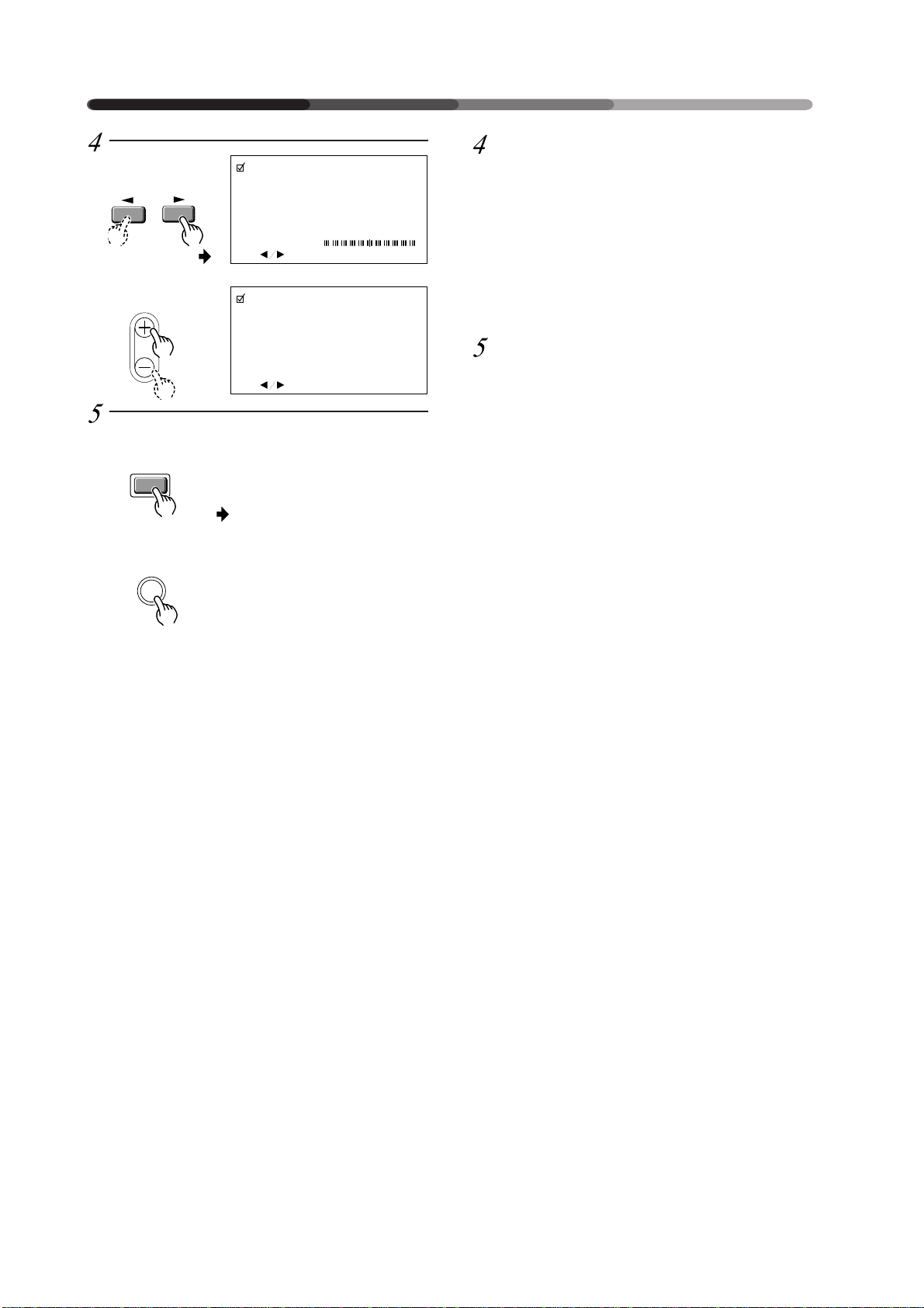
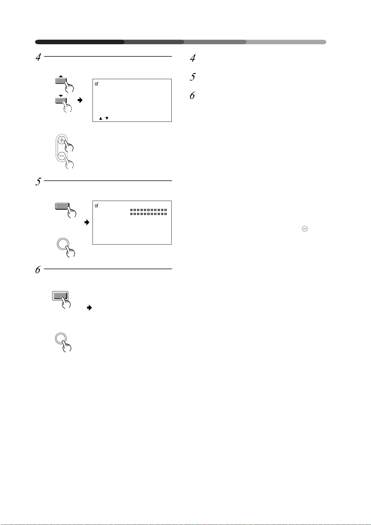
Adjust the picture quality concerning the selected item.
1 In case of CONTRAST and BRIGHT:
2 In case of CLK.FRQ., CLK PHS., HOR.POS. and
VER.POS.:
To return to the step-2 screen, press the SET button.
Repeat steps 2 through 4 to adjust the other items.
When you have completed the setting, return to the normal screen.
NOTE:
When the interlaced signals such as NTSC, PAL, etc.
are input from the RGB input terminal, adjust the
HOR. POS. and VER. POS. (horizontal and vertical
positions) so that the image becomes positioned in
the center of the screen.
The picture may not be reproduced properly if the
positions are altered extremely from the original
ones.
16
<ARE1348>
En/Fr/Ge
HOW TO ADJUST PICTURE QUALITY
COMMENT REGLER LA QUALITE DE L’IMAGE
EINSTELLEN DER BILDQUALITÄT
Réglage de la qualité de l’image
concernant l’option sélectionnée
1 En cas de CONTRAST et de BRIGHT
2 En cas de CLK.FRQ, CLK.PHS, HOR.POS et
VER.POS
Pour retourner à l’écran phase-2, appuyer sur le bouton SET.
Répéter les étapes 2 à 4 pour régler les autres options.
Une fois la sélection terminée,
revenir à l’écran normal
REMARQUE:
Lorsque des signaux imbriqués, tels que des signaux
NTSC, PAL, etc. sont envoyés au départ du terminal
d’introduction RGB, ajuster les POS. HOR. et POS.
VER. (positions horizontale et verticale) de manière
à positionner l’image au centre de l’écran.
Il se peut que l’image ne puisse pas être reproduite
correctement si les positions sont fortement
modifiées par rapport aux positions initiales.
Stellen Sie die Bildqualität der
gewählten Funktion ein.
1 Für CONTRAST und BRIGHT
2 Für CLK.FRQ, CLK.PHS., HOR.POS und VER.POS
Um zur Oberfläche von Schritt 2 zurückzukehren,
drücken Sie die SET-Taste.
Wiederholen Sie Schritte 2 bis 4, um auch die anderen
Funktionen einzustellen.
Wenn Sie die Bildeinstellung
abgeschlossen haben, kehren Sie zur
normalen Oberfläche zurück.
Anmerkung:
Wenn die Eingangssignale wie z.B. NTSC, PAL, usw.
über den RGB Eingang eingeleitet werden, müssen
HOR.POS und VER.POS (waagerechte und senkrechte
Position) so eingestellt werden, daß das Bild in der
Bildschirmmitte positioniert ist.
Werden die Positionen im Vergleich zur
Originalposition stark verändert, kann es passieren,
daß das Bild nicht ganz einwandfrei wiedergegeben
wird.
17
<ARE1348>
En/Fr/Ge
HOW TO ADJUST PICTURE QUALITY
COMMENT REGLER LA QUALITE DE L’IMAGE
EINSTELLEN DER BILDQUALITÄT
STANDBY
/ON
With RGB-1, when inputting RGB
SELECT
SET
Remote control
Commande à distance
Fernbedienung
MENU
Main unit
Unité principale
Hauptgerät
MENU
VIDEO
STANDBY/ON
Y/C
INPUT
MENU
RGB 1
RGB 2
P I CTURE PARAMETER
CONTRAST
I
GHT.
BR
CLK. FRQ.
CLK. PHS.
HOR. POS.
VER. POS.
I N I
T.
SCART RGB
SET : SEL. MENU : EXIT
INPUT
MENU
ADJUST
SET
+ 1 0
– 5
– 0
+ 8
OFF
output from a unit with a Euro
AV (SCART) terminal:
Switch to the MENU screen.
Scroll down to SCART RGB.
Press the SET button.
Remote control
Commande à distance
Fernbedienung
Main unit
Unité principale
Hauptgerät
ADJUST
Remote control
Commande à distance
Fernbedienung
SET
Main unit
Unité principale
Hauptgerät
SET
P I CTURE PARAMETER
CONTRAST
I
GHT.
BR
CLK. FRQ.
CLK. PHS.
HOR. POS.
VER. POS.
I N I
T.
SCART RGB
SET : SEL. MENU : EXIT
P I CTURE PARAMETER
SCART RGB ON
OFF
: CHANGE SET : SET
+ 1 0
– 5
– 0
+ 8
OFF
18
<ARE1348>
En/Fr/Ge
HOW TO ADJUST PICTURE QUALITY
COMMENT REGLER LA QUALITE DE L’IMAGE
EINSTELLEN DER BILDQUALITÄT
Avec RGB-1, lors de la connexion
d’une sortie RGB à une unité
équipée d’un terminal Euro AV
(SCART) :
Passez à l’écran MENU.
Faites-le défiler jusqu’à SCART RGB.
Appuyez sur le bouton de sélection
(SET).
Bei Empfang von RGB-Signalen
eines Geräts mit EURO A/VAnschluß (SCART) über RGB-1
Display MENU aufrufen.
SCART RGB wählen.
Eingabetaste (SET) drücken.
19
<ARE1348>
En/Fr/Ge
HOW TO ADJUST PICTURE QUALITY
COMMENT REGLER LA QUALITE DE L’IMAGE
EINSTELLEN DER BILDQUALITÄT
Remote control
Commande à distance
Fernbedienung
Main unit
Unité principale
Hauptgerät
ADJUST
Remote control
Commande à distance
Fernbedienung
SET
Main unit
Unité principale
Hauptgerät
SET
P I CTURE PARAMETER
SCART RGB ON
: CHANGE SET : SET
P I CTURE PARAMETER
CONTRAST
I
GHT.
BR
CLK. FRQ.
CLK. PHS.
HOR. POS.
VER. POS.
I N I
T.
SCART RGB
SET : SEL. MENU : EXIT
OFF
+ 1 0
– 5
– 0
+ 8
ON
Select SCART RGB ON.
Press the SET button.
When setting is completed, return to
the normal screen.
NOTE:
With the function set to RGB-1, when inputting RGB
output from a unit with a Euro AV (SCART) terminal,
always set SCART RGB to ON.
With the function set to RGB-1, when inputting RGB
output from a unit with a Euro AV (SCART) terminal,
always set SCART RGB to ON, and set the Sync Signal Input Impedance switch (
When inputting a signal other than RGB output, always set SCART RGB to OFF.
Before you perform the above settings, always first
turn OFF the power to the unit connected to RGB-1. If
you perform the above settings with the power to
the unit connected to RGB-1 remaining ON, in some
cases there may be nothing on the screen or remote
control operation will be ineffective.
If this occurs, turn OFF both the main unit
and the power to the unit connected to RGB-1, then
perform resetting.
0
on page 8) to 75 Ω.
button
Remote control
Commande à distance
Fernbedienung
MENU
Main unit
Unité principale
Hauptgerät
MENU
• Return to the normal
screen.
• Ë Retour à l’écran normal.
• Zurück zur normalen
Maske.
20
<ARE1348>
En/Fr/Ge
HOW TO ADJUST PICTURE QUALITY
COMMENT REGLER LA QUALITE DE L’IMAGE
EINSTELLEN DER BILDQUALITÄT
Sélectionnez SCART RGB ON.
Appuyez sur le bouton de sélection
(SET).
Une fois les réglages terminez,
revenez à l’écran normal.
NOTE:
Lorsque la fonction est réglée sur RGB-1, lors de la
connexion d’une sortie RGB à une unité équipée d’un
terminal Euro AV (SCART), réglez toujours SCART
RGB sur ON.
Lorsque la fonction est réglée sur RGB-1, lors de la
connexion d’une sortie RGB à une unité équipée d’un
terminal Euro AV (SCART), réglez toujours SCART
RGB sur ON et le commutateur d’impédance d’entrée
du signal de synchronisation (
Pour la connexion d’un autre signal, assurez-vous de
régler SCART RGB sur OFF.
Avant d’effectuer les réglages susmentionnés, veillez
à ce que l’unité connectée à RGB-1 soit HORS tension. Dans le cas contraire, il est possible que rien
n’apparaisse à l’écran ou que la commande à distance ne réponde pas.
Si tel était le cas, appuyez sur le bouton
principale et mettez l’unité connectée à RGB-1 HORS
tension et recommencez les réglages.
0
en page 8) sur 75 Ω.
de l’unité
Einstellung SCART RGB ON wählen.
Eingabetaste (SET) drücken.
Nach Beendigung der Eingabe
schaltet der Monitor auf das normale
Display.
Anmerkung:
Bei Empfang von RGB-Signalen eines Geräts mit
EURO A/V-Anschluß (SCART) über RGB-1 muß
SCART RGB stets auf ON gestellt werden.
Bei Empfang von RGB-Signalen eines Geräts mit
EURO A/V-Anschluß (SCART) über RGB-1 muß
SCART RGB stets auf ON gestellt werden. Den
Synchronsignaleingang-Impedanzschalter (
Ω
Seite 8) auf 75
Falls andere Signale als RGB-Signale zugeführt
werden, muß SCART RGB auf OFF gestellt werden.
Vor der Durchführung der obigen Einstellungen stets
die mit RGB-1 verbundene Signalquelle ausschalten.
Werden die Einstellungen bei eingeschalteter
Signalquelle vorgenommen, werden die Signale
unter Umständen nicht auf dem Monitor
wiedergegeben oder die Fernbedienung funktioniert
nicht.
Falls dies eintritt, den Bildschirm über Taste und
die mit RGB-1 verbundene Signalquelle ausschalten.
Dann das System rückstellen.
einstellen.
0
auf
21
<ARE1348>
En/Fr/Ge
HOW TO ADJUST PICTURE QUALITY
COMMENT REGLER LA QUALITE DE L’IMAGE
EINSTELLEN DER BILDQUALITÄT
Remote control
Commande à distance
Fernbedienung
MENU
Main unit
Unité principale
Hauptgerät
MENU
VIDEO
STANDBY/ON
Y/C
INPUT
SELECT
MENU
SET
RGB 1
RGB 2
<NTSC>
P I CTURE PARAMETER
CONTRAST
I
GHT.
BR
COLOR
I
NT
T
SHARPNESS
I N I
T.
SET : SEL. MENU : EX
<PAL>
P I CTURE PARAMETER
CONTRAST
I
GHT.
BR
COLOR
SHARPNESS
I N I
T.
STANDBY
/ON
INPUT
MENU
ADJUST
SET
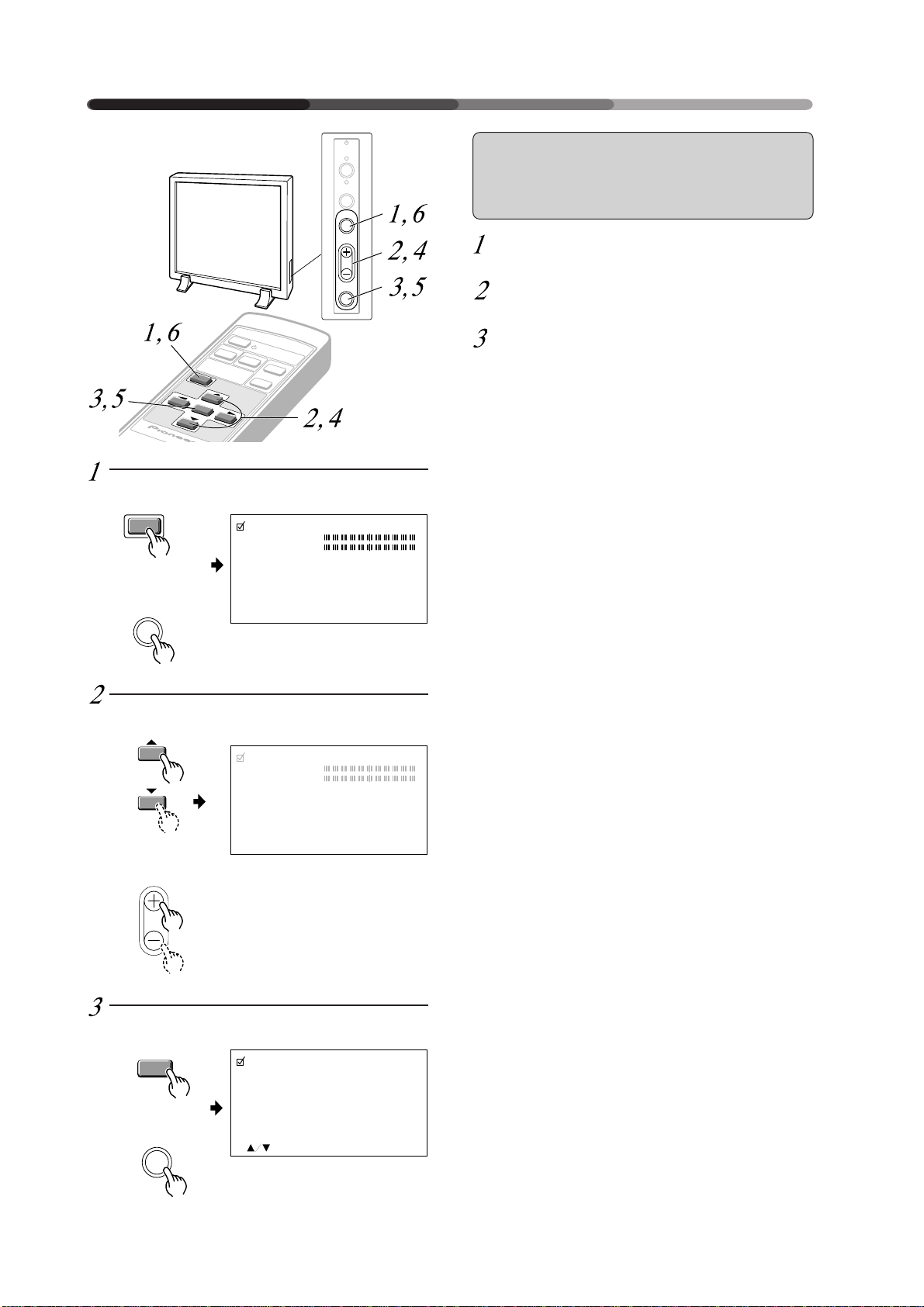
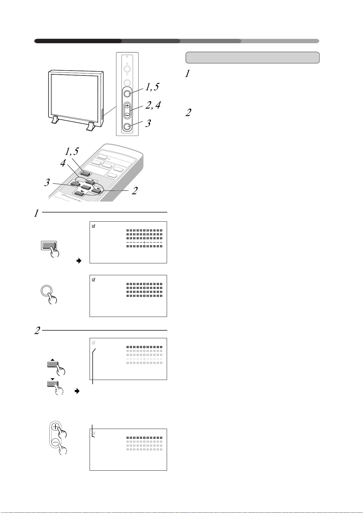
Video or Y/C Input
Switch to the MENU screen.
The currently selected item will be displayed in purple.
Choose the item to be adjusted.
I
T
Remote control
Commande à distance
Fernbedienung
Main unit
Unité principale
Hauptgerät
ADJUST
22
<ARE1348>
En/Fr/Ge
SET : SEL. MENU : EX
I
T
<NTSC>
P I CTURE PARAMETER
CONTRAST
I
GHT.
BR
COLOR
I
NT
T
SHARPNESS
I N I
T.
I
SET : SEL. MENU : EX
T
• The currently selected item will
be displayed in purple.
• L’option sélectionnée sera
affichée en pourpre
• Das gewählte Item wird
purpurfarbig wiedergegeben.
P I CTURE PARAMETER
CONTRAST
I
GHT.
BR
COLOR
SHARPNESS
I N I
T.
SET : SEL. MENU : EX
I
T
<PAL>

HOW TO ADJUST PICTURE QUALITY
COMMENT REGLER LA QUALITE DE L’IMAGE
EINSTELLEN DER BILDQUALITÄT
Entrée vidéo ou Y/C
Passer à l’écran MENU
L’option sélectionnée sera affichée en pourpre
Sélectionner l’article à régler
Video oder Y/C Eingang
Wechseln Sie zur MENU-Oberfläche.
Die gewählte Funktion wird purpurfarbig
wiedergegeben.
Wählen Sie die Funktion, die
eingestellt werden soll.
23
<ARE1348>
En/Fr/Ge
HOW TO ADJUST PICTURE QUALITY
COMMENT REGLER LA QUALITE DE L’IMAGE
EINSTELLEN DER BILDQUALITÄT
Remote control
Commande à distance
Fernbedienung
SET
Main unit
Unité principale
Hauptgerät
SET
Remote control
Commande à distance
Fernbedienung
Main unit
Unité principale
Hauptgerät
ADJUST
P I CTURE PARAMETER
CONTRAST
: ADJ. SET : EXIT
1
P I CTURE PARAMETER
CONTRAST
: ADJ. SET : EXIT
2
P I CTURE PARAMETER
T I NT
: ADJ. SET : EXIT
• Only in the NTSC mode
• Uniquement en mode NTSC.
• Nur im NTSC-Betrieb.
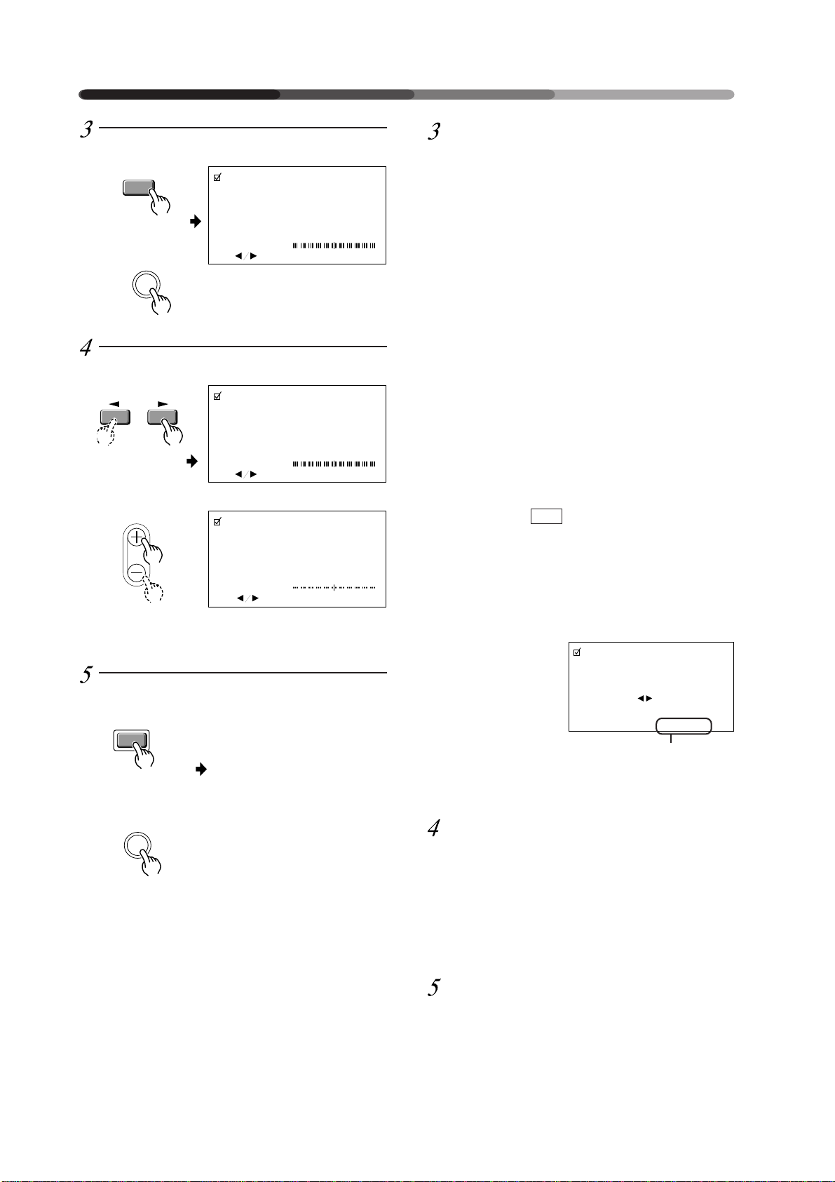
Finalize your choice.
Make adjustments for each item as follows:
CONTRAST .. Adjusts the contrast of the picture ac-
cording to the brightness of the environment so that you can watch the picture easier.
BRIGHT ......... Adjusts the brightness of the picture so
that you can watch the darker parts of
the picture, (such as night scenes and
dark hair), easier.
COLOR .......... Adjusts the color of the picture as de-
sired. (Set it to a little lower position
than that you want, to obtain natural
pictures.)
TINT .............. Adjusts the tint of the picture so that
the face color looks natural.
(Possible to adjust when the NTSC signal is inputted.)
SHARPNESS Normally set to their center values. But
if you want images to be displayed in
softer tones, adjust it to the left from
the center position.
INIT ............... Returns the above picture settings to
*1
When you select INIT. , the message on the right is
displayed. Select “YES” or “NO” by using the 2 or
3 button.
Selecting “YES” and pressing the SET button sets
back all picture quality settings to their default values.
When “NO” is selected, all settings will remain as
they are.
their center values. *1
P I CTURE PARAMETER
Remote control
Commande à distance
Fernbedienung
MENU
Main unit
Unité principale
Hauptgerät
MENU
• Returns to the normal
screen.
• Ë Retour à l’écran normal
• Zurück zur normalen
Maske.
I N I T I AL I ZE?
YES NO
I
SET : EX
T
If “NO” has been selected,
SET:EXIT will be displayed here.
If “YES” has been selected,
SET:INIT will be displayed.
Adjust the picture quality concerning the selected item.
1 In case of the items other than TINT:
2 In case of TINT:
To return to the step-2 screen, press the SET button.
Repeat Steps 2 through 4 to adjust the other items.
When you have completed the setting, return to the normal screen.
24
<ARE1348>
En/Fr/Ge
HOW TO ADJUST PICTURE QUALITY
COMMENT REGLER LA QUALITE DE L’IMAGE
EINSTELLEN DER BILDQUALITÄT
Finalisation de la sélection
Opérer les réglages pour chaque option comme suit :
CONTRAST ... Règle le contraste de l’image en fonction
de la luminosité de l’environnement de
manière à pouvoir visionner l’image
avec un plus grand confort.
BRIGHT .........Règle la luminosité de l’image de
manière à pouvoir visionner plus
facilement les parties plus sombres de
l’image (comme les scènes nocturnes
et une chevelure noire) avec un plus
grand confort.
COLOR ..........Règle la couleur de l’image selon les
desiderata (la régler sur une position
légèrement inférieure à celle que vous
recherchez pour obtenir des images
naturelles).
TINT .............. Règle les nuances de l’image de
manière à ce que les visages prennent
une coloration naturelle.
(Possibilité de règlage lorsque le signal NTSC est introduit.)
SHARPNESS .
INIT. ...............Ramène les sélections d’image
*1
Si vous sélectionnez INIT. , le message à droite est
affiché. Sélectionner “YES” ou “NO” en utilisant le
bouton 2 ou 3.
La sélection “YES” et l’enfoncement du bouton SET
réinitialise tous les réglages de qualité de l’image à
leurs valeurs par défaut.
Si “NO” est sélectionné, toutes les sélections restent
comme elles sont
Les définitions sont normalement
réglées sur leur valeur standard. Mais
si vous souhaitez que les images
affichées le soient dans des tonalités
plus douces, il suffit de régler à gauche
par rapport à la position centrale.
supérieures à leurs valeurs centrales. *1
P I CTURE PARAMETER
Bestätigen Sie Ihre Wahl.
Jede einzelne Funktion beinhaltet die nachstehenden
Einstellmöglichkeiten:
CONTRAST ... Regelt den Bildkontrast gemäß der
Helligkeit der Umgebung, zur besseren
Bilderkennung.
BRIGHT ......... Regelt die Helligkeit des Bildes, zur
besseren Erkennung der dunkleren
Bildstellen (z.B. Nachtaufnahmen,
dunkles Haar).
COLOR .......... Regelt die Farbsättigung nach Wunsch.
(Stellen Sie sie etwas schwächer ein,
um einen natürlichen Effekt zu
erreichen.)
TINT .............. Regelt die Farbphase, damit
Gesichtsfarben natürlich aussehen.
(Kann eingestellt werden beim
Eingang von NTSC-Signalen.)
SHARPNESS .
INIT ............... Setzt die oben genannten
*1
Wenn Sie INIT . wählen, wird die rechts dargestellte
Meldung wiedergegeben. Wählen Sie “YES“ oder
“NO“, indem sie die Taste 2 oder 3 drücken.
Wenn Sie “YES“ wählen und die SET-Taste drücken,
werden alle Bild-Einstellmöglichkeiten auf die
Standardwerte zurückgesetzt.
Wenn Sie “NO“ wählen, bleiben alle Einstellungen
unverändert.
Wird normalerweise auf den Mittelwert
eingestellt. Wenn Sie möchten, daß
das Bild weicher wirkt, wählen Sie
einen Wert links von der Mitte.
Bildeinstellungen auf ihren Mittelwert
zurück. *1
P I CTURE PARAMETER
I N I T I AL I ZE?
YES NO
SET : EX
I
T
I N I T I AL I ZE?
YES NO
SET : EX
I
T
Si “NO” a été sélectionné,
SET:EXIT sera affiché ici.
Si “YES” a été sélectionné,
SET:INIT sera affiché.
Réglage de la qualité de l’image
concernant l’option sélectionnée
1 Dans le cas d’options autres que TINT :
2 Dans le cas de TINT :
Pour retourner à l’écran step-2, appuyer sur le bouton SET.
Répéter les étapes 2 à 4 pour le réglage des autres
options.
Une fois la sélection terminée,
retourner à l’écran normal.
Wenn “NO“ gewählt wurde,
wird hier SET:EXIT angezeigt.
Wenn “YES“ gewählt wurde,
wird hier SET:INIT angezeigt.
Stellen Sie die Bildqualität der
gewählten Funktion ein.
1 Für alle anderen Funktionen als TINT
2 Für TINT
Um zur Oberfläche von Schritt 2 zurückzukehren,
drücken Sie die SET-Taste. Wiederholen Sie Schritte
2 bis 4, um die anderen Funktionen einzustellen.
Wenn Sie die Bildeinstellung
abgeschlossen haben, kehren Sie zur
normalen Oberfläche zurück.
25
<ARE1348>
En/Fr/Ge
INSTALLATION
INSTALLATION
MONTAGE
Using the Display
with Stands
Front
1
Avant
Vorderseite
590
Back
Arrière
Rückseite
100
2
AA'
AA
Utilisation de l’écran
avec supports
3
100
Unit: mm
Unité: mm
Einheit mm
4
• Use a hexagonal wrench. (6 mm)
• Utiliser une clé hexagonale (6 mm)
’
• Verwenden Sie einen Sechskantschlüssel (6 mm).
Benutzung des
Displays auf Sockeln
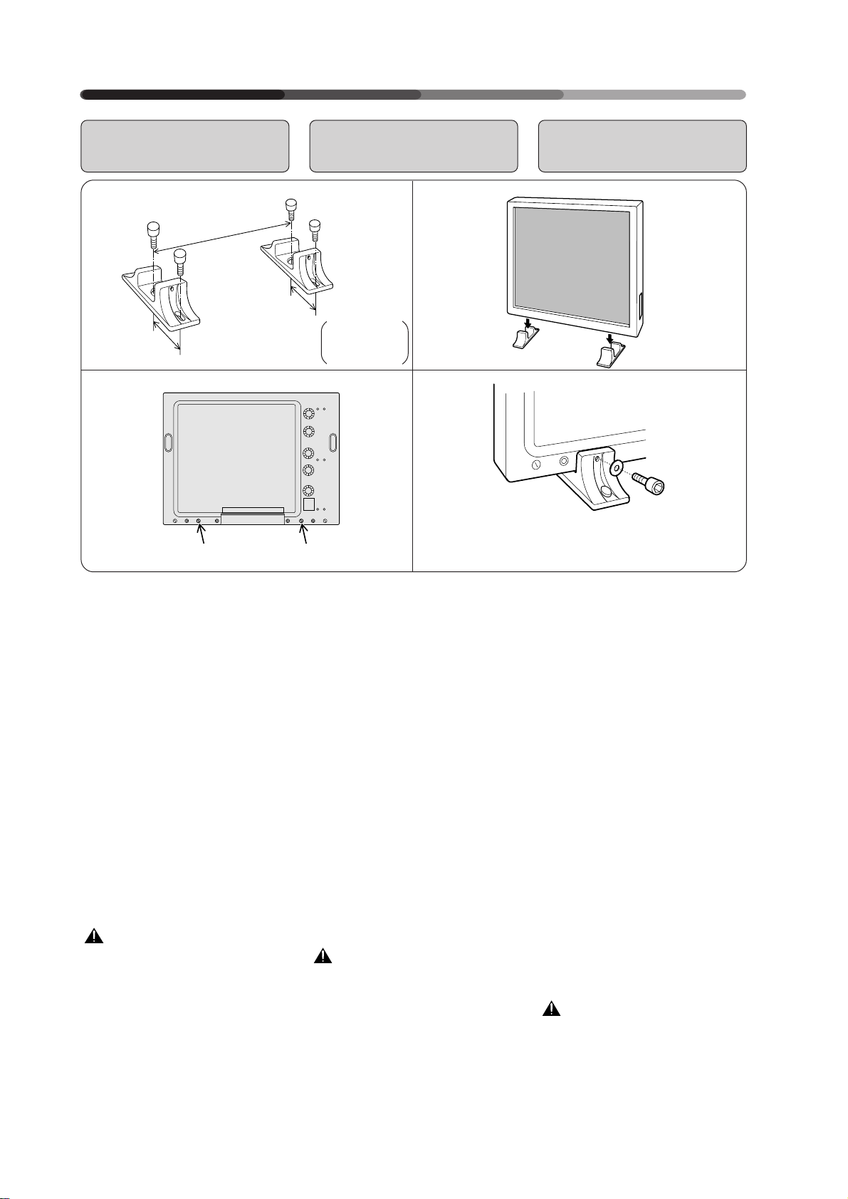
Always be sure to have your display installed by a trained professional or by your dealer.
To use the stands provided with the
main unit, fit the main unit with
them in accordance with the following procedure:
1. Use four bolts to fix the
stands provided with
the display on the display stand.
2. Use a coin to remove
hole rivets A and A’.
3. Insert the main unit
into the stands.
4. Fix the main unit with
the washers and bolts.
CAUTION
Because this display has an extremely small footprint for its heavy
weight of 31,6 kilograms, it is very
unstable. Always be sure to work
together with another person when
unpacking, carrying, or installing
the display.
26
<ARE1348>
En/Fr/Ge
Toujours faire installer l’écran par
un professionnel compétent ou par
le revendeur attitré.
Pour utiliser les supports prévus
avec l’unité principale, monter ces
supports selon la procédure ciaprès.
1. Utiliser quatre boulons
pour fixer les supports
fournis avec l’écran.
2. Utiliser une pièce de
monnaie pour enlever
les rivets A et A’.
3. Introduire l’unité
principale dans les supports.
4. Fixer l’unité principale
avec les rondelles et les
boulons.
ATTENTION
Etant donné que cet écran se
caractérise par un contact au sol
extrêmement réduit pour un poids
élevé (31,6 kg), il se révèle très instable. Toujours travailler avec une
autre personne lors du déballage,
du transport ou de l’installation de
l’écran.
Lassen Sie Ihr Display immer von
einem Fachmann oder von Ihrem
Fachhändler montieren.
Wenn Sie die mit dem Hauptgerät
gelieferten Sockel verwenden
möchten, montieren Sie das
Display bitte wie nachfolgend
beschrieben:
1. Befestigen Sie die mit
dem Gerät gelieferten
Sockel mit vier
Schrauben auf der
Unterlage.
2. Entfernen Sie die
Abdeckplättchen A und
A’ mit Hilfe einer Münze.
3. Stellen Sie das Display
auf die Sockel.
4. Befestigen Sie das
Display mit den
Unterlegscheiben und
den Schrauben.
Vorsicht
Da das Gerät gemessen an seinem
Gewicht von 31,6 kg ein extrem
kleines Gehäuse hat, ist es
besonders instabil. Lassen Sie sich
deshalb beim Auspacken, Tragen
oder Montieren immer von einer
zweiten Person helfen.
INSTALLATION
INSTALLATION
MONTAGE
Installing the Display
on a wall or Other Flat
Surfaces
Installation de l’écran
sur un mur ou d’autres
surfaces plates
Montage des Displays
an einer Wand oder an
anderen Flächen
12
13 to 20 mm
13-20mm
13 à 20 mm
13 bis 20 mm
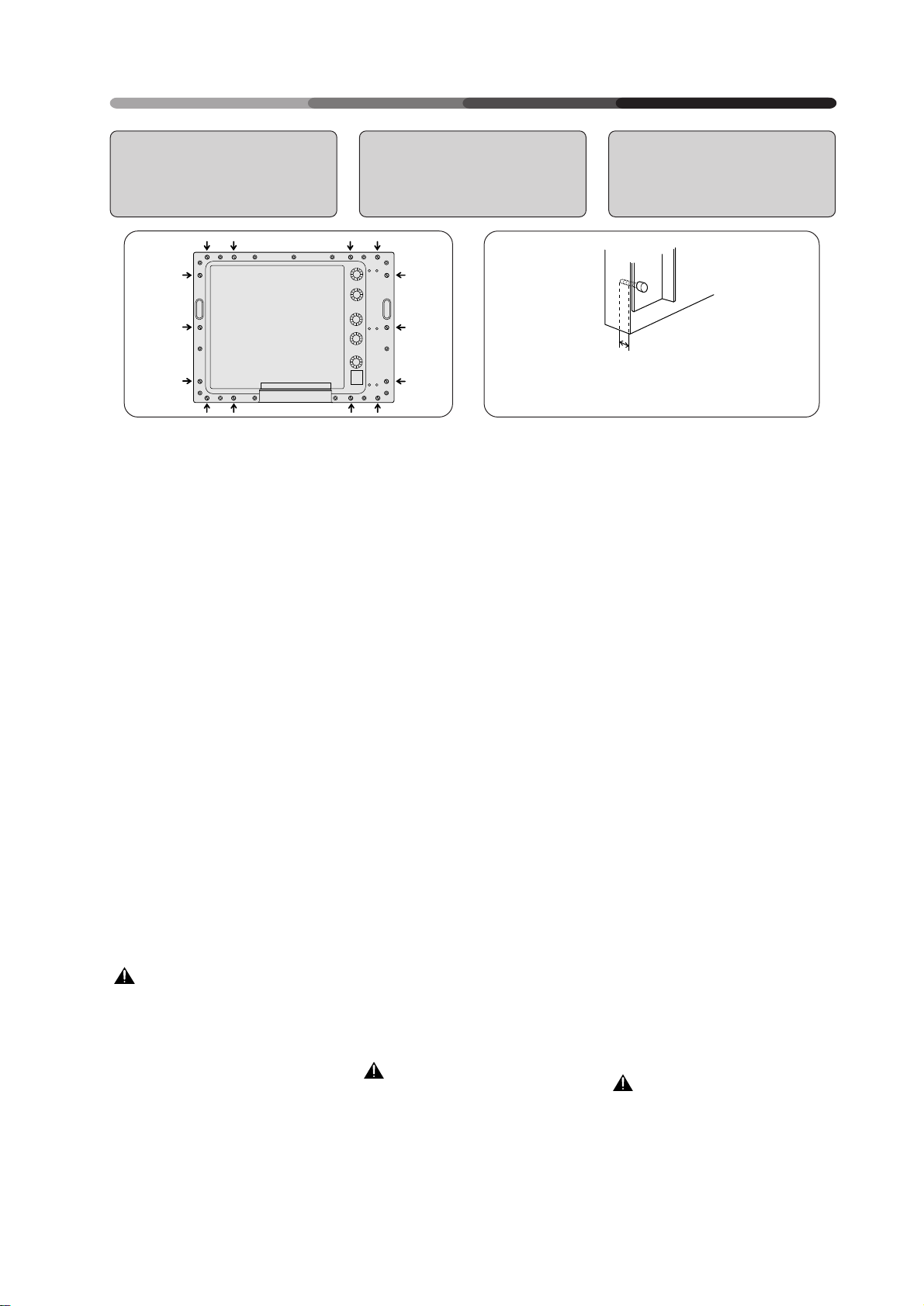
The display comes with bolt holes
for attaching to a wall or other flat
surface.
1. To use metal fittings for
installation
Remove the hole rivets (indicated
by arrows in the diagram above)
and attach the metal fittings.
When installing fittings or installing
the display, always be sure to have
the work done by a trained professional or by your dealer.
2. Precautions on use of
metal fittings for installation
• Use bolts (M8) which is to be left
by 13 to 20 mm inside the unit
when fastened.
For installation positions, contact
your nearest Pioneer authorized
service station.
Note that Pioneer bears no responsibility whatsoever for any problems in installation/attachment nor
for any accidents or damages
caused by natural disasters, etc.
WARNING
Use bolts which are less than 20
mm long inside the unit when fastened. Use of longer bolts will lead
to damage of the internal circuit,
electrical hazards, fire hazards, etc.
L’écran est fourni avec des trous de
boulon qui permettent sa fixation à
un mur ou une autre surface plane.
1. Utilisation de raccordements métalliques pour
l’installation
Enlever les rivets des orifices (c-à-d
ceux indiqués par une flèche sur le
schéma ci-dessus) et fixer les
accessoires métalliques.
Lors de l’installation des accessoires
ou de l’installation de l’écran,
toujours faire réaliser ce travail par
un professionnel compétent ou par
le revendeur attitré.
2. Précautions d’utilisation
de raccordements
métalliques pour
l’installation
• Utiliser les boulons (M8) qui
doivent laisser un espace libre de
13 à 20 mm à l’intérieur de l’écran
lorsqu’ils sont fixés.
Pour les positions d’installation,
prendre contact avec votre service
après-vente PIONEER agréé le
plus proche.
Il est à noter que Pioneer n’est
aucunement responsable de tous
problèmes d’installation/de
raccordement, ni d’accidents ou
d’endommagements provoqués par
des catastrophes naturelles, etc.
AVERTISSEMENT
Utiliser des boulons d’une longueur
inférieure à 20 mm à l’intérieur de
l’unité lors de sa fixation.
L’utilisation de boulons plus longs
peut endommager le circuit interne,
entraîner des risques électriques,
un danger d’incendie etc.
Das Display ist mit Schraublöchern
für die Befestigung an einer Wand
oder an sonstigen Flächen versehen.
1. Verwendung von
MetallBefestigungsteilen für
die Montage
Entfernen Sie die Abdeckplättchen
von den Löchern (in der
obenstehenden Skizze mit Pfeilen
gekennzeichnet) und befestigen Sie
die Metall-Befestigungsteile.
Die Montage der Befestigungsteile
oder des Displays sollte immer von
einem Fachmann oder von Ihrem
Fachhändler ausgeführt werden.
2. Vorsichtsmaßnahmen
bei der Montage mit
MetallBefestigungsteilen
• Verwenden Sie Schrauben (M8), die
nach dem Festschrauben noch 13
bis 20 mm tief im Gerät verbleiben.
Lassen Sie sich von Ihrem
zuständigen PioneerVertragshändler die für die Montage
geeigneten Stellen aufzeigen.
Bitte beachten Sie, daß Pioneer
weder für Probleme, die bei der
Montage/Befestigung auftreten,
noch für Unfälle oder Schäden, die
durch Naturkatastrophen usw.
entstehen, eine Haftung übernimmt.
Warnung:
Verwenden Sie Schrauben, die nach
dem Festschrauben weniger als 20
mm in das Gerät hineinragen. Die
Verwendung längerer Schrauben
führt zu Beschädigungen im
Geräteinneren und damit eventuell
zu elektrischen Störungen, Feuer
usw.
<ARE1348>
En/Fr/Ge
27
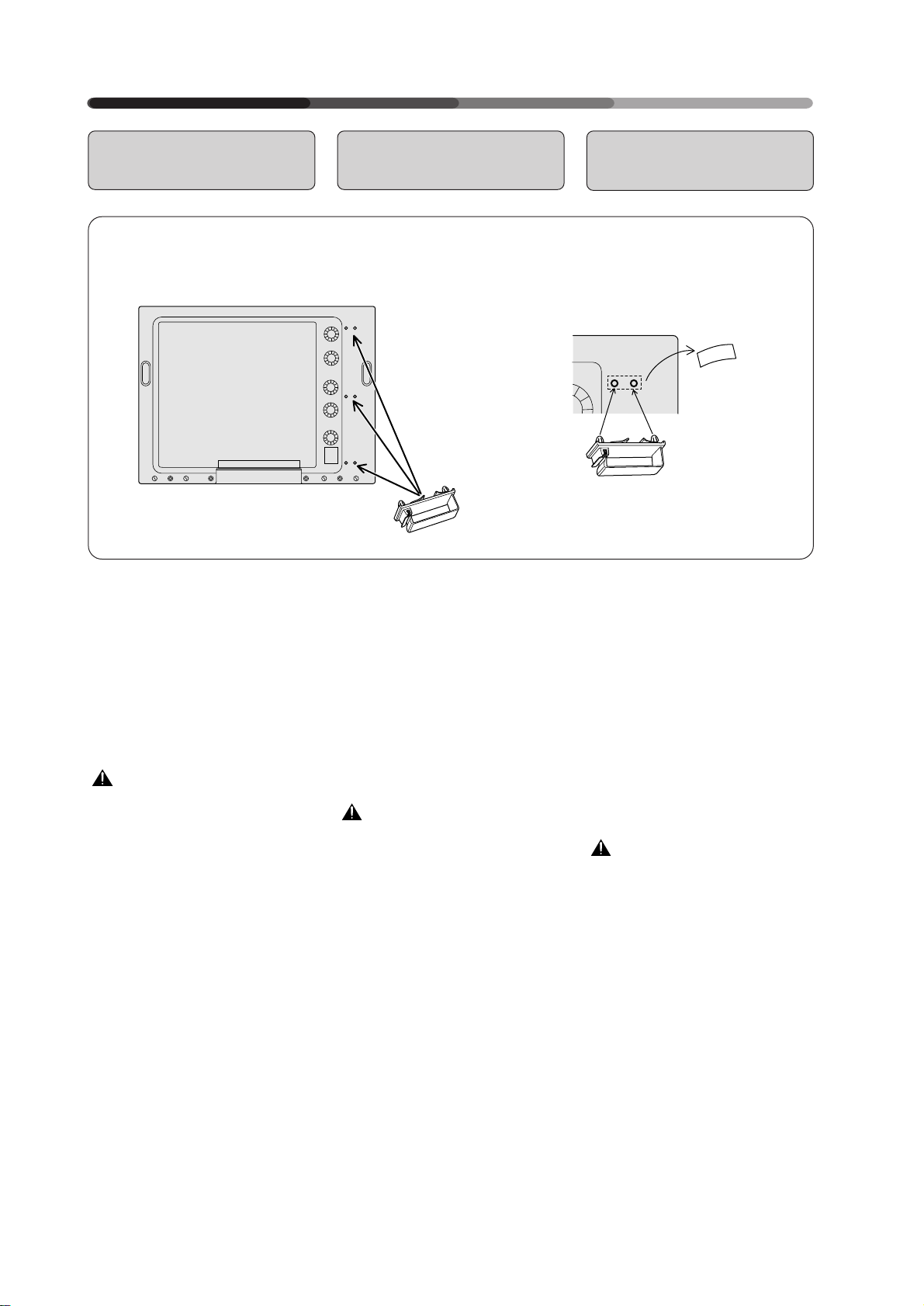
INSTALLATION
INSTALLATION
MONTAGE
How to Fit the Display
with Cable Clamps
<Back of the main unit>
<Arrière de l’unité principale>
< Rückseite des Hauptgerätes>
Three cable clamps are provided to
bind the connecting cables.
Follow the procedure below to attach the clamps to the display.
Remove the label on the rear of the
display, insert the cable clamp into
the two holes shown in the diagram
above, and press firmly until you
hear a clicking sound.
CAUTION
When using the cable clamps provided with your display, always be
sure to remove the label covering
the holes into which the clamp is
to be fitted before inserting the
clamp into place.
Note that inserting cables into the
cable clamp may prevent proper
ventilation, and that when using the
cable clamp you should therefore
be sure to keep the display a distance of 10 centimeters or more
away from any walls or other surfaces.
Comment équiper
l’écran de serre-câbles
Trois serre-câbles sont fournis pour
fixer les câbles de raccordement.
Se conformer à la procédure cidessous pour fixer les serre-câbles
en question à l’écran.
Enlever l’étiquette à l’arrière de
l’écran, insérer le serre-câbles dans
les deux orifices illustrés sur le
schéma ci-dessus et comprimer le
serre-câbles fermement jusqu’à ce
qu’un déclic se fasse entendre.
ATTENTION
Lors de l’utilisation des serre-câbles
fournis avec l’écran, toujours vérifier que l’on a enlevé l’étiquette recouvrant les orifices dans lesquels les
serre-câbles doivent être montés
avant de mettre celui-ci en place.
A noter que l’insertion de câbles
dans le serre-câbles peut empêcher
une ventilation adéquate.
L’utilisation du serre-câbles, il faut
donc veiller à conserver une distance
de 10 cm ou plus entre l’écran et tout
mur ou autre surface quelconque.
Montage des Displays
mit Kabelklemmen
Für die Befestigung der
Anschlußkabel werden drei
Kabelklemmen mitgeliefert.
Zur Befestigung der Klemmen am
Display befolgen Sie bitte die
nachstehend beschriebenen
Arbeitsschritte:
Entfernen Sie den Aufkleber an der
Rückseite des Displays, führen Sie
die Kabelklemme wie oben
abgebildet in die beiden Öffnungen
ein und drücken Sie sie fest, bis sie
einrastet.
Vorsicht
Wenn Sie die mit Ihrem Display
gelieferten Kabelklemmen
verwenden, entfernen Sie immer
zunächst den Aufkleber von den
Öffnungen, in denen die Klemmen
befestigt werden, bevor Sie die
Klemmen befestigen.
Beachten Sie, daß durch das
Einklemmen eines Kabels in die
Kabelklemmen die
ordnungsgemäße Lüftung
beeinträchtigt werden kann. Wenn
Sie die Kabelklemmen benutzen,
sollten Sie deshalb einen Abstand
von mindestens 10 Zentimetern zur
Wand oder zu anderen Flächen
einhalten.
28
<ARE1348>
En/Fr/Ge
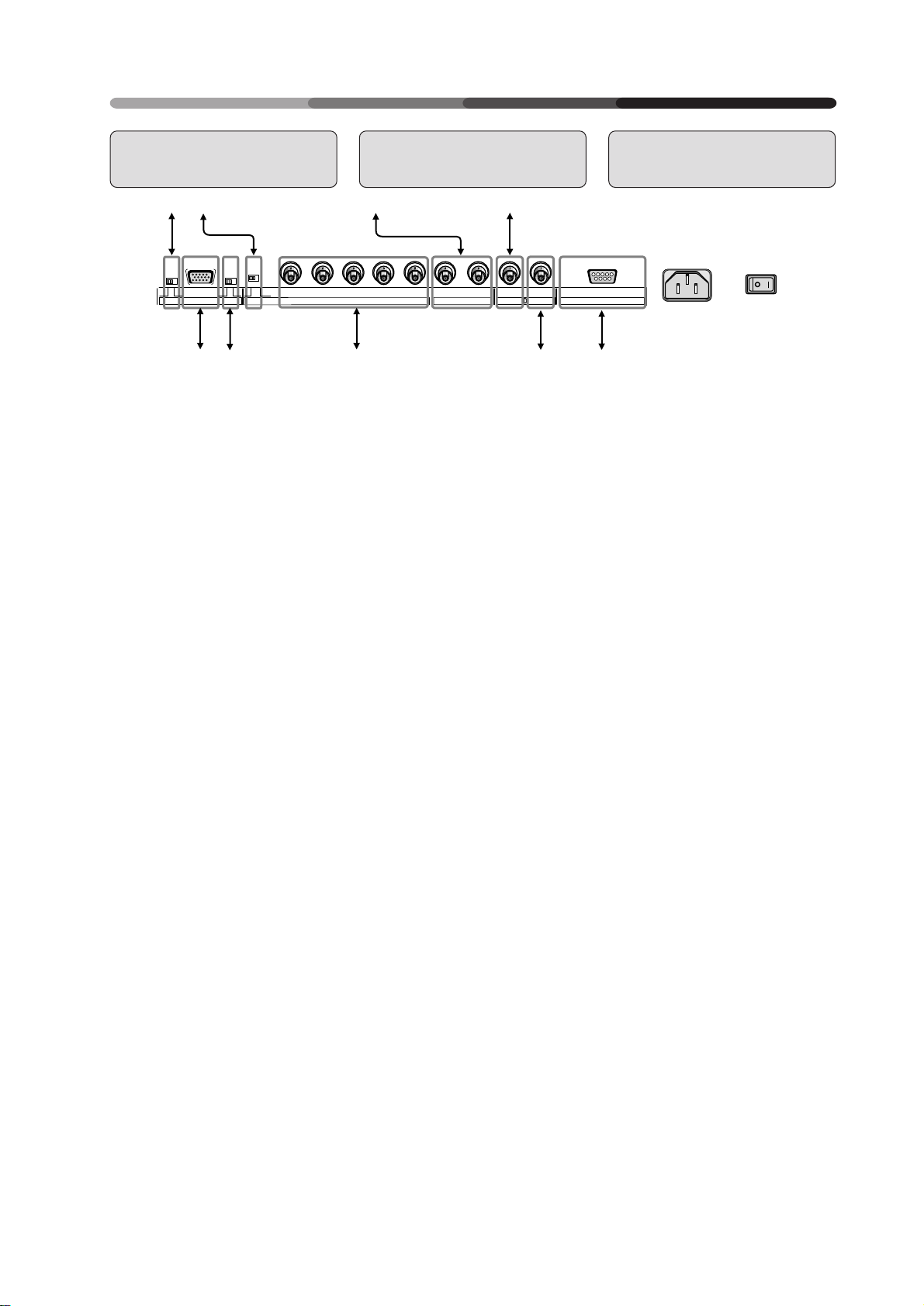
CONNECTIONS
CONNEXIONS
ANSCHLÜSSE
Diagram of Equipment connected
1
2
(Ω)
75 2.2k
OFF ONOFF ON
5
67
1 This switch will output remote
control commands from the
RGB-2 (D-SUB 15-pin) terminal
to control external peripheral
devices planned for future sales
release. Normally be sure to use
set to OFF.
2 Switch this according to the out-
put impedance of the sync signal of the device connected
when inputting to RGB1.
Set to 2.2 kΩ when the output
impedance of the sync signal of
the device is other than 75 Ω.
3 To: Video equipment with the Y/
C separation output, such as
VCRs for business use
4 To:TV monitor, and other equip-
ment with input terminal
NOTE:
VIDEO OUT is output only when the
VIDEO IN signal POWER ON.
5 To: Personal computers
6 If the images become greenish
when an external device is connected to the RGB-2 input terminal, turn ON the G on SYNC
mode. Normally set to OFF.
7 To: Personal computers, exter-
nal RGB decoders, or other devices with RGB output ports
8 To: VCRs, video cameras, laser
disc players, DVD players, or
other devices with video OUTPUT ports
9 To: Personal computers, when
controlling the Plasma Display
with the personal computer.
* In case of a 25-pin RS-232C connecter,
use a conversion connector available
on your local market.
* Refer to page 51 for the sources.
VD HD B G R C Y OUT IN
SYNCREMOTE G ON SYNC
(H/V SYNC) RGB-1 (ON SYNC) Y/C VIDEO RS-232CRGB-2
Schéma de l’équipement
connecté
34
89
1 Ce contacteur émet les
commandes à distance en provenance de la borne RGB-2 (DSUB 15 broches) vers les
périphériques externes qui
seront vendus à l’avenir.
S’assurer que le réglage est sur
OFF.
2 Actionner ce bouton en fonction de
l’impédance de sortie du signal
sync du dispositif connecté lors de
l’entrée dans RGB1.
Régler sur 2,2 KΩ lorsque
l’impédance de sortie du signal
sync du dispositif est différente de
75Ω.
3 Vers : Equipement vidéo avec sor-
tie de séparation Y/C, comme les
magnétoscopes à cassette à usage
professionnel.
4 Vers : Moniteur TV et autres
matériels à terminal à borne
d’entrée
NOTE :
VIDEO OUT est sorti uniquement si le
signal VIDEO IN est activé (POWER
ON).
5 Vers : Ordinateurs personnels
6 Si les images deviennent verdâtres
lorsqu’un dispositif extérieur est
raccordé au terminal d’entrée RGB2, amener G sur le mode SYNC.
Normalement, celui-ci est réglé sur
OFF (=arrêt).
7 Vers : Ordinateurs personnels,
décodeurs RGB extérieurs ou
autres dispositifs avec ports de
sortie RGB
8 Vers : Magnétoscopes à cassette,
caméras vidéo, lecteurs de disques
laser, lecteurs DVD ou autres
dispositifs avec ports de sortie
vidéo.
9 Vers : Ordinateurs personnels en
cas de commande de l’écran à
plasma par un ordinateur personnel
* En cas d’utilisation d’un connecteur RS-
232C à 25 broches, utiliser un connecteur
de conversion vendu localement.
* Référez-vous à la page 52 pour les
sources.
Übersicht der
Anschlußmöglichkeiten
1 Mit diesem Schalter können
Fernbedienungsbefehle über
den Anschluß RGB-2 (D-SUB,
15-Pin-Buchse) ausgegeben
werden, um zukünftiges
Zubehör zu steuern.
Für den Normalbetrieb
unbedingt auf OFF stellen.
2 Schalten Sie dies gemäß der
Ausgangsimpedanz des
Synchronisierungssignals des
angeschlossenen Gerätes bei Input
nach RGB1.
Stellen Sie auf 2.2 kΩ ein, wenn die
Ausgangsimpedanz des
Synchronisierungssignals einen
anderen Wert als 75 Ω aufweist.
3 An: Videogeräte mit Y/C-
getrenntem Ausgang, wie auch
Videorecorder für den
professionellen Gebrauch.
4 An: TV-Monitore und andere
Geräte mit einem Video-Eingang.
Anmerkung:
VIDEO Out ist nur dann ein Ausgang,
wenn das Display eingeschaltet ist.
5 An: Personal Computer
6 Werden die Bilder grünlich, sobald
ein externes Gerät an der InputSchnittstelle von RGB-2angeschlossen wird, schalten Sie
G am SYNC-Moduswählschalter
auf ON (EIN), während es
normalerweise auf OFF (AUS)
steht.
7 An: Personal Computer, externe
RGB-Decoder oder sonstige
Geräte mit RGB-Ausgang;
8 An: Videorecorder, Videokameras,
Disc-Player, DVD-Player, oder
sonstige Geräte mit Video-FBASAusgang;
9 An: Personal Computer, wenn das
Plasma-Display über einen PC
bedient wird.
* Wenn Sie einen 25-Pin RS-232C
Anschluß benutzen, sollten Sie einen
Übergangsstecker verwenden, der bei
Ihrem Händler erhältlich ist.
* Die Quellen finden Sie auf Seite 53
dieser Bedienungsanleitung.
29
<ARE1348>
En/Fr/Ge
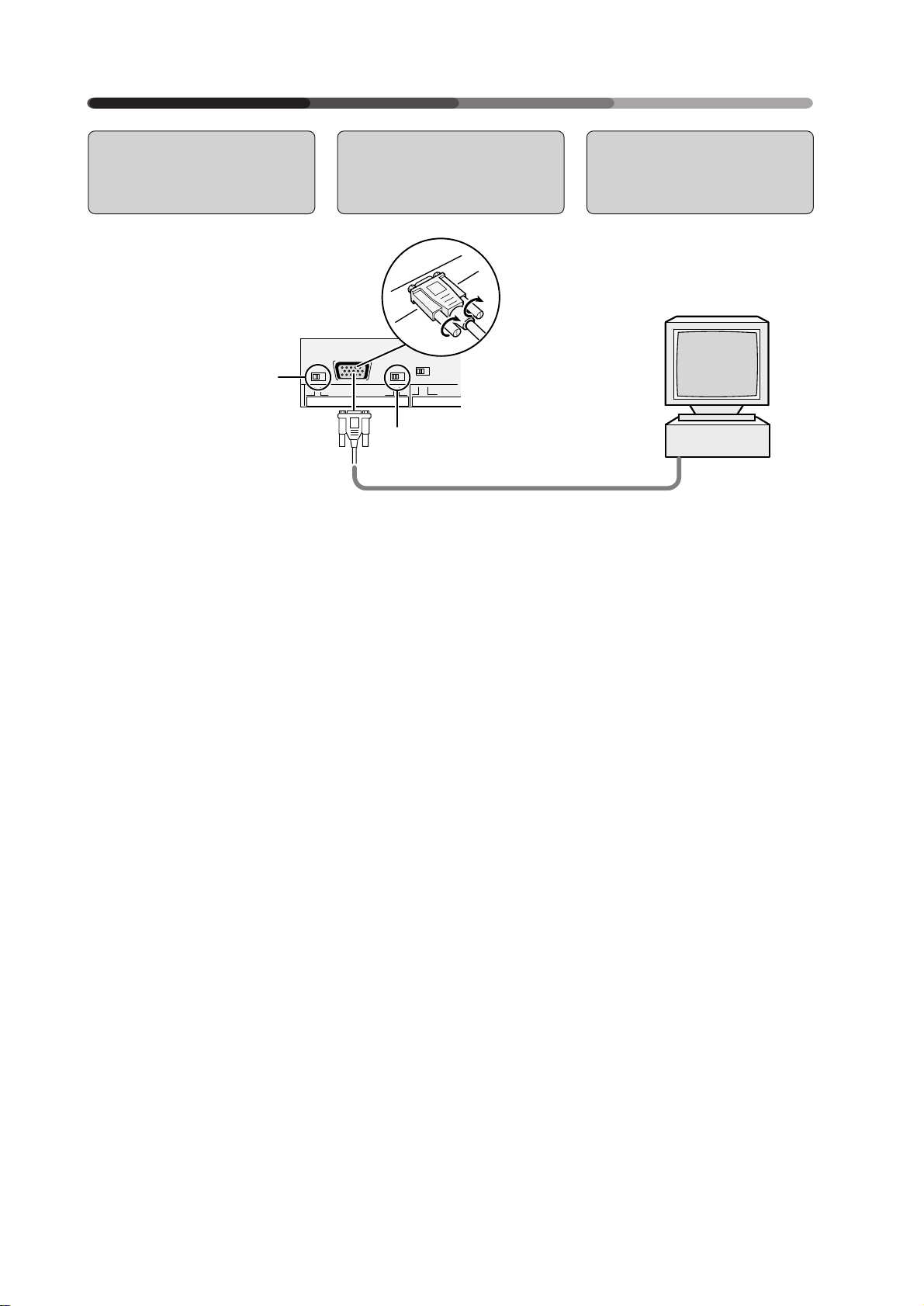
CONNECTIONS
CONNEXIONS
ANSCHLÜSSE
Connecting a Personal Computer to
the Display
• Desk-top type:
• Type de bureau
• Desktop
• Normally be sure to use set
to OFF.
• En temps normal, assurezvous d’être en position
OFF.
• Für den Normalbetrieb
unbedingt auf OFF stellen.
The method of connecting a personal computer to the unit varies
with the type of computer. Before
connecting the computer, read the
instruction manual for the computer also.
Connexion d’un
ordinateur personnel
à l’écran
(Ω)
75 2.2k
OFF ONOFF ON
RGB-2
La méthode de connexion d’un
ordinateur personnel à l’écran varie
en fonction du type d’ordinateur.
Avant de raccorder l’ordinateur, lire
également le manuel d’utilisation
de l’ordinateur.
SYNCREMOTE G ON SYNC
1
2
Anschluß eines
Personal Computers
an das Display
3
Das Verfahren beim Anschließen
eines Personal Computers an das
Gerät hängt vom jeweiligen
Computermodell ab. Lesen Sie
deshalb auch die Bedienungsanleitung des Computers.
7 In case of an IBM per-
sonal computer or A/T
compatible machines :
You can use your Plasma Display
together with the computer only in
the VGA mode.
(640 dots × 480 lines / Horizontal
scanning frequency: 31.47 kHz / Vertical scanning frequency: 59.94 Hz)
(640 dots × 480 lines / Horizontal
scanning frequency: 37.9 kHz / Vertical scanning frequency: 72.8 Hz)
(640 dots × 480 lines / Horizontal
scanning frequency: 37.5 kHz / Vertical scanning frequency: 75 Hz)
1 G on Sync mode selection
switch
If the images become greenish
when an external device is connected to the RGB-2 input terminal, turn ON the G on SYNC
mode. Normally set to OFF.
2 Computer connecting cable
(available on your local market)
3 Connect to the monitor output
terminal
30
<ARE1348>
En/Fr/Ge
7 Dans le cas d’un ordina-
teur personnel IBM ou
de compatibles A/T :
Vous pouvez utiliser votre écran à
plasma avec un ordinateur en mode
VGA uniquement (640 points × 480
lignes/fréquence de balayage horizontal : 31,47 kHz/fréquence de
balayage verticale : 59,94 Hz).
(640 points × 480 lignes/fréquence
de balayage horizontal : 37,9 kHz/
fréquence de balayage verticale :
72,8 Hz).
(640 points × 480 lignes/fréquence
de balayage horizontal : 37,5 kHz/
fréquence de balayage verticale : 75
Hz).
1 G sur bouton de sélection du
mode Sync
Si les images deviennent
verdâtres lorsqu’un dispositif
extérieur est raccordé au
terminal d’entrée RGB-2,
amener G sur le mode SYNC.
Normalement, celui-ci est réglé
sur OFF (=arrêt).
2 Câble de connexion pour
ordinateur
(disponible localement)
3 Connexion au terminal de sor-
tie du moniteur
7 IBM Computer oder A/
T-kompatible Geräte
Das Plasma-Display kann nur im
VGA-Betrieb zusammen mit dem
Computer verwendet werden. (640
Punkte x 480 Zeilen)/ Horizontale
Frequenz: 31,47 kHz/ Vertikale
Frequenz: 59,94 Hz).
(640 Punkte x 480 Zeilen)/
Horizontale Frequenz: 37,9 kHz/
Vertikale Frequenz: 72,8 Hz).
(640 Punkte x 480 Zeilen)/
Horizontale Frequenz: 37,5 kHz/
Vertikale Frequenz: 75 Hz).
1 G am Synchronisierungs-
Moduswählschalter
Werden die Bilder grünlich, sobald
ein externes Gerät an der InputSchnittstelle von RGB-2angeschlossen wird, schalten Sie
G am SYNC-Moduswählschalter
auf ON (EIN), während es
normalerweise auf OFF (AUS)
steht.
2 Computeranschlußkabel
(erhältlich bei ihrem
Fachhändler)
3 Anschließen an den Ausgang
des Monitors.

• Notebook type:
• Type bloc-notes
• Notebook
CONNECTIONS
CONNEXIONS
ANSCHLÜSSE
• Normally be sure to use set
to OFF.
• En temps normal, assurezvous d’être en position
OFF.
• Für den Normalbetrieb
unbedingt auf OFF stellen.
1 G on Sync mode selection
switch
If the images become greenish
when an external device is
connected to the RGB-2 input
terminal, turn ON the G on
SYNC mode. Normally set to
OFF.
2 Computer connecting cable
(available on your local market)
When inserting the cable, be sure
to confirm the shape of the signal input terminal of the Display
and that of the connecting cable
connector. After inserting the
cable, fix it securely by fastening
the side screws.
NOTES :
• Notebook-type personal computers with a built-in LCD panel of
VGA display type may have an
external RGB output which is
non-VGA. In this case, images are
not reproduced on the main unit.
The external RGB output should
be set to the VGA mode.
• Depending on the model of the
computer to be connected, a conversion connector and an analog
RGB output adapter, etc., which
are attached to the computer or
sold separately, are needed to
connect the cord to the computer.
For details, refer to your nearest
dealer.
(Ω)
75 2.2k
OFF ONOFF ON
RGB-2
SYNCREMOTE G ON SYNC
1
2
1 G sur bouton de sélection du
mode Sync
Si les images deviennent
verdâtres lorsqu’un dispositif
extérieur est raccordé au
terminal d’entrée RGB-2,
amener G sur le mode SYNC.
Normalement, celui-ci est réglé
sur OFF (=arrêt).
2 Câble de connexion pour
ordinateur
(disponible localement)
Lors de l’insertion du câble, ne pas
oublier de confirmer la forme de
la borne d’entrée du signal de
l’écran et celle du connecteur du
câble de connexion. Après
l’insertion du câble, fixer celui-ci
en serrant les vis latérales.
NOTES :
• Les ordinateurs personnels du
type bloc-notes avec panneau LCD
incorporé pour type d’écran VGA
peuvent posséder une sortie RGB
extérieure qui est non-VGA. Dans
ce cas, les images ne seront pas
reproduites sur l’écran principal.
La sortie RGB extérieure devra être
amenée en mode VGA.
• En fonction du modèle
d’ordinateur à raccorder, un
connecteur de conversion et un
adaptateur de sortie RGB
analogique etc., qui sont raccordés
à l’ordinateur ou bien vendus
séparément, sont nécessaires
pour raccorder le cordon à
l’ordinateur. Pour tous détails, consulter le revendeur le plus proche.
1 G am Synchronisierungs-
Moduswählschalter
Werden die Bilder grünlich, sobald
ein externes Gerät an der InputSchnittstelle von RGB-2angeschlossen wird, schalten Sie
G am SYNC-Moduswählschalter
auf ON (EIN), während es
normalerweise auf OFF (AUS)
steht.
2 Computeranschlußkabel
(erhältlich bei ihrem Fachhändler)
Wenn Sie das Kabel einstecken,
sollten Sie immer die Form des
Signal-Eingangs des Displays mit der
Form des Anschlußkabelsteckers
vergleichen. Wenn Sie das Kabel
eingesteckt haben, befestigen Sie es
sorgfältig mit den zwei seitlichen
Schrauben.
Anmerkung:
• Notebook-Computer mit
eingebautem LCD-Bildschirm des
VGA-Modells haben manchmal
einen externen RGB-Ausgang, der
kein VGA-Modell ist. In dem Fall
werden am Hauptgerät keine Bilder
wiedergegeben. Der externe RGBAusgang sollte auf VGA-Betrieb
eingestellt werden.
• Je nach Computermodell ist es
erforderlich, einen
Übergangsstecker und einen
Adapter für die analoge RGBSchnittstelle usw. zu benutzen, um
das Kabel mit dem Computer zu
verbinden. Diese Teile werden
entweder mit dem Computer
geliefert oder sind im Handel
erhältlich. Informieren Sie sich bei
Ihrem zuständigen Fachhändler.
31
<ARE1348>
En/Fr/Ge

RGB-2
OFF ONOFF ON
75 2.2k
(Ω)
SYNCREMOTE G ON SYNC
CONNECTIONS
CONNEXIONS
ANSCHLÜSSE
7 In case of a Macintosh, a
computer from the NEC
PC-9800 series, or a machine compatible with
one of these computers:
• Desk-top type:
• Type de bureau :
• Desktop
• Normally be sure to use set
to OFF.
• En temps normal, assurezvous d’être en position
OFF.
• Für den Normalbetrieb
unbedingt auf OFF stellen.
7 Dans le cas d’un ordina-
teur Macintosh, un ordinateur de la série NEC PC9800 ou une machine
compatible avec l’un des
ordinateurs suivants :
1
2
7 Macintosh-Computer
der NEC PC-9800-Serie
oder Geräte, die mit
einem dieser Computer
kompatibel sind.
3
Macintosh:
You can use your Plasma Display together with the computer in the 13inch mode.
(640 dots × 480 lines / Horizontal
scanning frequency: 35,00 kHz /
Vertical scanning frequency: 66,67
Hz)
PC-9800:
Normal Mode:
(640 dots × 400 lines/horizontal
scanning frequency 24.83 kHz/
vertical scanning frequency 56.42
Hz, or 640 dots × 400 lines/horizontal
scanning frequency 31.5 kHz/vertical
scanning frequency 70 Hz)
DOS/V or Windows VGA mode:
(640 dots x 480 lines/horizontal
scanning frequency 31.47 kHz/
vertical scanning frequency 59.94
Hz)
• This may not be applicable for some
models. Refer to the instruction
manual for the computer used for
details.
1 G on Sync mode selection switch
If the images become greenish
when an external device is
connected to the RGB-2 input
terminal, turn ON the G on SYNC
mode. Normally set to OFF.
2 Computer connecting cable
(available on your local market)
3 A conversion adapter
(available on your lacal market)
32
<ARE1348>
En/Fr/Ge
Macintosh :
Vous pouvez utiliser votre écran
plasma avec l’ordinateur en mode
13 pouces (640 points × 480 lignes/
fréquence de balayage horizontale :
35,00 kHz/fréquence de balayage
verticale : 66,67 Hz).
PC-9800:
Mode normal :
(640 points x 400 lignes/fréquence
de balayage horizontal 24,83 kHz/
fréquence de balayage vertical 56.42
Hz ou 640 x 400 lignes/fréquence de
balayage horizontal 31,5 kHz/
fréquence de balayage vertical (70
Hz).
Mode DOS/V ou Windows VGA:
(640 points x 480 lignes/fréquence
de balayage horizontal 31,47 kHz/
fréquence de balayage vertical
59,942 kHz).
• Ceci peut ne pas s’appliquer à
certains modèles. Se reporter au
manuel d’utilisation de l’ordinateur
utilisé pour plus de détails.
1 G sur bouton de sélection du mode
Sync
Si les images deviennent verdâtres
lorsqu’un dispositif extérieur est
raccordé au terminal d’entrée RGB2, amener G sur le mode SYNC.
Normalement, celui-ci est réglé sur
OFF (=arrêt).
2 Câble de raccordement à
l’ordinateur
(disponible localement)
3 Adaptateur de conversion
(disponible localement)
Macintosh:
Ihr Plasma-Display kann im 13-ZollBetrieb zusammen mit diesem
Computer verwendet werden (640
Punkte x 480 Zeilen) / Horizontale
Frequenz: 35,00 kHz / Vertikale
Frequenz: 66,67 Hz).
PC-9800:
Normalmodus:
(640 Punkte x 400 Zeilen/horizontale
Abtastfrequenz 24.83 kHz/vertikale
Abtastfrequenz 56.42 Hz oder 640
Punkte x 400 Zeilen/horizontale
Abtastfrequenz 31.5 kHz/vertikale
Abtastfrequenz 70 Hz)
DOS/V oder Windows VGA-Modus:
(640 Punkte x 480 Zeilen/
horizontale Abtastfrequenz 31.47
kHz/vertikale Abtastfrequenz
59.94 Hz)
• Auf einige Modelle mag dies nicht
zutreffen. Einzelheiten darüber
entnehmen Sie bitte der
Bedienungsanweisung des
verwendeten Computers.
1 G am Synchronisierungs-
Moduswählschalter
Werden die Bilder grünlich, sobald
ein externes Gerät an der InputSchnittstelle von RGB-2angeschlossen wird, schalten Sie
G am SYNC-Moduswählschalter
auf ON (EIN), während es
normalerweise auf OFF (AUS)
steht.
2 Computeranschlußkabel
(erhältlich bei Ihrem Fachhändler)
3 Übergangsstecker
(erhältlich bei Ihrem Fachhändler)

RGB-2
OFF ONOFF ON
75 2.2k
(Ω)
SYNCREMOTE G ON SYNC
• Notebook type:
• Type bloc-notes :
• Notebook:
• Normally be sure to use set
to OFF.
• En temps normal, assurezvous d’être en position
OFF.
• Für den Normalbetrieb
unbedingt auf OFF stellen.
CONNECTIONS
CONNEXIONS
ANSCHLÜSSE
3
1
2
1 G on Sync mode selection switch
If the images become greenish
when an external device is
connected to the RGB-2 input
terminal, turn ON the G on SYNC
mode. Normally set to OFF.
2 Computer connecting cable
(available on your local market)
3 A conversion adapter provided
with the notebook-type computer.
Or available on your local market.
When inserting the cable, be sure to
confirm the shape of the signal input
terminal of the Display and that of
the connecting cable connector. After
inserting the cable, fix it securely by
fastening the side screws.
NOTES :
• Notebook-type personal computers
with a built-in LCD panel of VGA
display type may have an external
RGB output which is non-VGA. In
this case, images are not reproduced
on the main unit. The external RGB
output should be set to the VGA
mode.
• The computer manufacturers, product names, etc. appearing in this
manual are the trademarks or registered trademarks of the respective
companies.
• Some Macintosh models output
both the G-on-SYNC and composite
SYNC signals, which causes the
screen to become greenish. In this
case, turn ON the G on SYNC mode
switch. Normally be sure to use set
to OFF.
1 G sur bouton de sélection du mode
Sync
Si les images deviennent verdâtres
lorsqu’un dispositif extérieur est
raccordé au terminal d’entrée RGB2, amener G sur le mode SYNC.
Normalement, celui-ci est réglé sur
OFF (=arrêt).
2 Câble de raccordement à
l’ordinateur
(disponible localement)
3 Adaptateur de conversion (fourni
avec l’ordinateur de type blocnotes, ou disponible localement).
Lors de l’insertion du câble, ne pas
oublier de confirmer la forme de la
borne d’entrée du signal de l’écran
et celle du connecteur du câble de
connexion. Après l’insertion du câble,
fixer celui-ci en serrant les vis
latérales.
NOTES :
• Les ordinateurs personnels du type
bloc-notes avec panneau LCD
incorporé pour type d’écran VGA
peuvent posséder une sortie RGB
extérieure qui est non-VGA. Dans ce
cas, les images ne seront pas
reproduites sur l’écran principal. La
sortie RGB extérieure devra être
amenée en mode VGA.
• Les constructeurs d’ordinateurs, les
noms de produits etc. figurant dans
ce manuel sont des marques de
commerce ou des marques de
commerce déposées des sociétés en
question.
• Certains modèles Macintosh
sortent à la fois les signaux G-onSYNC et SYNC composites, ce
qui provoque le verdissement de
lӎcran. Dans ce cas, actionner G
sur l’interrupteur du mode SYNC.
Bien s’assurer que la position
normale est OFF (=arrêt).
1 G am Synchronisierungs-
Moduswählschalter
Werden die Bilder grünlich, sobald
ein externes Gerät an der InputSchnittstelle von RGB-2angeschlossen wird, schalten Sie
G am SYNC-Moduswählschalter
auf ON (EIN), während es
normalerweise auf OFF (AUS)
steht.
2 Computeranschlußkabel
(erhältlich bei Ihrem Fachhändler)
3 Übergangsstecker, zusammen mit
dem Notebook-Computer
geliefert. Sonst erhältlich bei Ihrem
Fachhändler.
Wenn Sie das Kabel einstecken,
sollten Sie immer die Form des
Signal-Eingangskabels des Displays
mit der Form des
Anschlußkabelsteckers vergleichen.
Wenn Sie das Kabel eingesteckt
haben, befestigen Sie es sorgfältig
mit den zwei seitlichen Schrauben.
Anmerkung:
• Notebook-Computer mit
eingebautem LCD-Bildschirm des
VGA-Modells haben manchmal
einen externen RGB-Ausgang, der
kein VGA-Modell ist. In diesem Fall
werden am Hauptgerät keine Bilder
wiedergegeben. Der externe RGBAusgang sollte auf VGA-Betrieb
eingestellt werden.
• Die in dieser Bedienungsanleitung
genannten Computerhersteller,
Produktnamen usw. sind
Markennamen oder eingetragene
Schutzmarken der jeweiligen
Unternehmen.
• Einige Macintosh‚-Modelle
geben sowohl G-on-SYNC als
auch Frequenzgemische
(zusammengesetzte Signale) aus,
was den Schirm grünlich werden
läßt. Schalten Sie in diesem Fall
G am SYNC-Moduswählschalter
auf ON (EIN), während es
normalerweise auf OFF (AUS)
stehen muß.
33
<ARE1348>
En/Fr/Ge

CONNECTIONS
CONNEXIONS
ANSCHLÜSSE
Connecting Video Devices to the Display
(Ω)
OFF ON
RGB-2
75 2.2kOFF ON
VD HD B G R C Y OUT IN
SYNCREMOTE G ON SYNC
(H/V SYNC) RGB-1 (ON SYNC) Y/C VIDEO RS-232C
Connexion
d’équipements vidéo
à l’écran
1
Anschluß von
Videogeräten an das
Display
2
3
4
5
1. In case of a composite
video source, such as a
VCR or TV tuner:
1 BNC
2 Cable with BNC terminals avail-
able on the local market
3 BNC
4 V OUT
5 VCR, TV tuner or the like
NOTE :
If the composite video output terminal of the VCR or the like, to be
connected, is an RCA pin terminal,
use an RCA
(available on your local market).
⇔
BNC converter plug
1. En cas de source vidéo
composite, telle que
magnétoscope à cassette ou tuner TV :
1 BNC
2 Câble avec bornes BNC
disponible localement
3 BNC
4 V OUT BNC
5 Magnétoscope à cassette, tuner
TV ou analogues
NOTE :
Si le terminal de sortie vidéo composite du magnétoscope à cassette,
ou analogue, à raccorder est un terminal à broche RCA, utiliser une
prise d’adaptation RCA
(disponible localement).
⇔
BNC
1. Zusammengesetzte
Videoquellen wie z.B.
Videorecorder oder TVTuner.
1 BNC
2 Kabel mit BNC-Stecker,
erhältlich bei Ihrem
Fachhändler.
3 BNC
4 V OUT BNC
5 Videorecorder, TV-Tuner oder
ähnliche Geräte
Anmerkung:
Wenn der kombinierte Video-Ausgang
des Videorecorders oder eines
anderen Gerätes an einen RCA-PinAusgang angeschlossen werden muß,
verwenden Sie bitte einen RCA
BNC-Übergangsstecker (erhältlich bei
Ihrem Händler).
⇔
34
<ARE1348>
En/Fr/Ge

OFF ON
RGB-2
(Ω)
75 2.2kOFF ON
VD HD B G R C Y OUT IN
SYNCREMOTE G ON SYNC
(H/V SYNC) RGB-1 (ON SYNC) Y/C VIDEO RS-232C
34
2222
1
CONNECTIONS
CONNEXIONS
ANSCHLÜSSE
4
3
6
2
3
5
(1) Device outputting Y/C separation
from BNC terminals/
(1) Dispositif de sortie de la séparation
Y/C à partir des bornes BNC
(1) Gerät mit Y/S getrenntem Ausgang
über BNC-Schnittstellen
2. In case of a device with
the Y/C separation output
1 Cable with BNC terminals avail-
able on the local market
2 BNC
3 C
4 Y
5 VCR for business use or the like
6 S-terminal ⇔ BNC-terminal
converter cable available on
the local market
7 S-terminal
8 VCR with an S-terminal or the
like
2
4
(2) Device outputting Y/C separation with
an S-terminal/
(2) Dispositif de sortie pour séparation Y/C
avec borne S
(2) Gerät mit Y/S getrenntem Ausgang mit
einer S-VHS-Schnittstelle.
2. En cas de dispositif avec
sortie de séparation Y/
C
1 Câble avec bornes BNC
disponible localement
2 BNC
3 C
4 Y
5 Magnétoscope à cassette à us-
age professionnel ou analogue
6 Câble pour conversion borne
S ⇔ borne BNC disponible
localement
7 Borne S
8 Magnétoscope à cassette avec
borne S ou analogue
7
8
2. Geräte mit einem Y/C
getrennten Ausgang
1 Kabel mit BNC-Steckern,
erhältlich bei Ihrem örtlichen
Händler.
2 BNC
3 C
4 Y
5 VCR für professionelle
Anwendungen oder ähnliche
Geräte
6 S-VHS-Schnittstelle ⇔ BNC-
Schnittstelle Übergangskabel,
erhältlich bei Ihrem
Fachhändler.
7 S-VHS-Schnittstelle
8 Videorecorder mit einer S-VHS-
Schnittstelle oder ähnliche
Geräte.
35
<ARE1348>
En/Fr/Ge

CONNECTIONS
CONNEXIONS
ANSCHLÜSSE
3. In case of G-on-SYNC
RGB analog source devices
(How to connect the display to a
device which provides green-signal
output with the synchronizing signal)
(Ω)
1
75 2.2kOFF ON
VD HD B G R C Y OUT IN
SYNCREMOTE G ON SYNC
(H/V SYNC) RGB-1 (ON SYNC) Y/C VIDEO RS-232C
2
OFF ON
RGB-2
3. Dans le cas de
dispositifs à source
analogique G-sur-SYNC
RGB :
(Comment raccorder l’écran à un
dispositif qui donne une sortie à signal vert avec le signal de
synchronisation)
34 5
6
2
35
3. Geräte mit G-nachSync RGB analogen
Quellen
(Anschluß des Displays an Geräte,
die mit dem Synchronsignal einen
Grünsignal-Ausgang liefern.)
7
1 G on Sync mode selection
switch
If the images become greenish
when an external device is
connected to the RGB-2 input
terminal, turn ON the G on
SYNC mode. Normally set to
OFF.
2 BNC
3 B
4 G
5 R
6 Cable with BNC terminals avail-
able on the local market
7 G (on SYNC)
8 VCR or RGB decoder for busi-
ness use
NOTES :
• If you use your Plasma Display in
this way, don’t connect any device to its VD or HD terminal. Otherwise images may not properly
be reproduced.
• When inputting a signal to RGB1, always perform the RGB-1
menu setting on page 14.
8
1 G sur bouton de sélection du mode
Sync
Si les images deviennent verdâtres
lorsqu’un dispositif extérieur est
raccordé au terminal d’entrée RGB2, amener G sur le mode SYNC.
Normalement, celui-ci est réglé sur
OFF (=arrêt).
2 BNC
3 B
4 G
5 R
6 Câble avec bornes BNC
disponible localement
7 G (sur SYNC)
8 Magnétoscope à cassette ou
décodeur RGB à usage
professionnel
NOTES :
• Si vous utilisez votre écran à
plasma de cette façon, ne
raccorder aucun dispositif à sa
borne VD ou HD. Dans le cas
contraire, les images peuvent ne
pas être reproduites correctement.
• Lors de l’entrée d’un signal en
RGB-1, il faut toujours effectuer
le réglage indiqué à la page 15
dans le menu RGB-1.
1 G am Synchronisierungs-
Moduswählschalter
Werden die Bilder grünlich, sobald
ein externes Gerät an der InputSchnittstelle von RGB-2angeschlossen wird, schalten Sie
G am SYNC-Moduswählschalter
auf ON (EIN), während es
normalerweise auf OFF (AUS)
steht.
2 BNC
3 B
4 G
5 R
6 Kabel mit BNC-Eingängen,
erhältlich bei Ihrem
Fachhändler.
7 G (nach SYNC)
8 Videorecorder oder RGB-
Decoder für professionelle
Anwendungen.
Anmerkungen:
• Wenn Sie Ihr Plasma- Display für
diese Anwendung einsetzen,
sollten Sie keine Geräte über
die VD- oder HD-Schnittstelle
anschließen. Sonst werden
die Bilder nicht einwandfrei
wiedergegeben.
• Bei Signaleingang über RGB-1
stets die auf Seite 15 erläuterte
Menüeinstellung für RGB-1
vornehmen.
36
<ARE1348>
En/Fr/Ge

CONNECTIONS
CONNEXIONS
ANSCHLÜSSE
4. In case of compositesync RGB analog
source devices
(How to connect the display to a
device which provides horizontal
and vertical synchronizing signals)
(Ω)
RGB-2
75 2.2kOFF ON
VD HD B G R C Y OUT IN
SYNCREMOTE G ON SYNC
(H/V SYNC) RGB-1 (ON SYNC) Y/C VIDEO RS-232C
1
2345
OFF ON
1 Switch this according to the out-
put impedance of the sync signal of the device connected
when inputting to RGB-1.
When the sync-signal output impedance is not 75 Ω, position the
switch to 2,2 kΩ.
2 (H/V SYNC)
3 B
4 G
5 R
6 Cable with BNC terminals avail-
able on the local market
7 (H/V)
8 VCR or RGB decoder for busi-
ness use or the like
NOTES :
• If you use your Plasma Display in
this way, don’t connect any device to its VD terminal. Otherwise
images may not properly be reproduced.
• Some Macintosh models may
output both the G ON SYNC and
composite SYNC. In such cases,
the screen becomes greenish
when composite SYNC is output.
For such models, connect the G
on SYNC of step 3.
• When inputting a signal to RGB-
1, always perform the RGB-1
menu setting on page 14.
4. En cas de dispositif à
source analogique RGB
à synchronisation composite
(Comment raccorder l’écran à un
dispositif qui fournit des signaux de
synchronisation horizontaux et
verticaux)
6
73 45
1 Actionner ce bouton en fonction
de l’impédance de sortie du signal sync du dispositif connecté
lors de l’entrée dans RGB-1.
Si l’impédance de sortie du signal de synchronisation n’est pas
égale à 75 Ω, positionner
l’interrupteur sur 2,2 kΩ.
2 (H/V SYNC)
3 B
4 G
5 R
6 Câble avec bornes BNC disponi-
bles localement
7 (H/V)
8 Magnétoscope à cassette ou dé-
codeur RGB à usage professionnel ou analogue.
NOTES :
• Si vous utilisez votre écran à plas-
ma de cette façon, ne pas connecter de dispositif à sa borne VD.
Dans le cas contraire, les images
peuvent ne pas être reproduites
correctement.
• Certains modèles Macintosh peu-
vent sortir à la fois G ON SYNC et
SYNC composite. En pareil cas,
l’écran devient verdâtre si SYNC
composite est sorti.
Pour ces modèles, raccorder le G
on SYNC de l’étape 3.
• Lors de l’entrée d’un signal en
RGB-1, il faut toujours effectuer
le réglage indiqué à la page 15
dans le menu RGB-1.
4. Geräte mit RGBanaloger Quelle
(Anschluß des Displays an Geräte,
die horizontale und vertikale
Synchronsignale liefern.)
8
1 Schalten Sie dies gemäß der
Ausgangsimpedanz des Synchronisierungsignals des angeschlossenen Geräts bei Input
nach RGB-1.
Wenn die Impedanz des SignalAusgangs nicht 75 Ω, beträgt,
sollten Sie auf 2,2 kΩ, umschalten.
2 (H/V SYNC)
3 B
4 G
5 R
6 Kabel mit BNC-Steckern, er-
hältlich bei Ihrem Fachhändler
7 (H/V)
8 Videorecorder oder RGB-Decod-
er für professionelle Anwendungen oder ähnliche Geräte
Anmerkungen:
• Wenn Sie Ihr Plasma-Display für
diese Anwendung benutzen,
sollten Sie keine Geräte an die
VD-Schnittstelle anschließen.
Sonst werden die Bilder nicht einwandfrei wiedergegeben.
• Manche Macintosh-Modelle ha-
ben sowohl einen G-nach-Synchron- als auch einen getrennten
Synchronsignal-Ausgang. Bei
solchen Geräten wird der Bildschirm grünlich, wenn das Synchronsignal als Ausgang benutzt
wird.
Für solche Modelle muß der Anschluß gemäß Schritt 3 erfolgen.
• Bei Signaleingang über RGB-1
stets die auf Seite 15 erläuterte
Menüeinstellung für RGB-1
vornehmen.
37
<ARE1348>
En/Fr/Ge

CONNECTIONS
CONNEXIONS
ANSCHLÜSSE
5. In the case of an RGB
analog source with
separate sync signals
(The RGB output has green, blue
and red signals, and horizontal and
vertical sync signals)
(Ω)
RGB-2
1
75 2.2kOFF ON
VD HD B G R C Y OUT IN
SYNCREMOTE G ON SYNC
(H/V SYNC) RGB-1 (ON SYNC) Y/C VIDEO RS-232C
3
2
OFF ON
1 Switch this according to the out-
put impedance of the sync signal of the device connected
when inputting to RGB-1.
When the sync-signal output impedance is not 75 Ω, position the
switch to 2,2 kΩ.
2 Cable with BNC terminals avail-
able on the local market
3 BNC
4 VD
5 HD
6 B
7 G
8 R
9 (1) VCR or RGB decoder for
business use or the like
0 BNC - MINI Dsub 15 converter
cable available on the local market
- Personal computer
= (2) When connection a per-
sonal computer
NOTES :
• When you connect a personal
computer as shown above, you
may need an adapter depending
on the type of the computer. For
details, consult the personal computer manufacturer or the computer dealer.
• When inputting a signal to RGB-
1, always perform the RGB-1
menu setting on page 14.
5. Dans le cas d’une source
analogique RGB avec
des signaux de
synchronisation séparés
(La sortie RGB présente des
signaux verts, bleus et rouges et
des signaux de synchronisation
horizontaux et verticaux)
45678
3
45678
9
1 Actionner ce bouton en fonction
de l’impédance de sortie du signal sync du dispositif connecté
lors de l’entrée dans RGB-1.
Si l’impédance de sortie du signal de synchronisation n’est pas
égale à 75 Ω, positionner
l’interrupteur sur 2,2 kΩ.
2 Câble avec bornes BNC
disponible localement.
3 BNC
4 VD
5 HD
6 B
7 G
8 R
9 (1) Magnétoscope à cassette ou
décodeur RGB pour usage
professionnel ou analogue.
0 Câble pour conversion BNC-MINI
Dsub 15 disponible localement
- Ordinateur personnel
= (2) En cas de connexion à un
ordinateur personnel
NOTES :
• Si vous connectez un ordinateur
personnel comme celui illustré cidessus, il peut être nécessaire de
disposer d’un adaptateur en
fonction du type d’ordinateur.
Pour tous détails, consulter le
constructeur ou le revendeur
d’ordinateurs personnels.
• Lors de l’entrée d’un signal en
RGB-1, il faut toujours effectuer
le réglage indiqué à la page 15
dans le menu RGB-1.
5. Geräte mit RGB
analoger Quelle und
getrennten
Synchronsignalen
(Der RGB-Ausgang hat Grün-, Blauund Rotsignale, wie auch
horizontale und vertikale
Synchronsignale.)
0
=
1 Schalten Sie dies gemäß der
Ausgangsimpedanz des Synchronisierungsignals des angeschlossenen Geräts bei Input
nach RGB-1.
Wenn die Impedanz des SignalAusgangs nicht 75 Ω, beträgt,
sollten Sie auf 2,2 kΩ, umschalten.
2 Kabel mit BNC-Schnittstelle, er-
hältlich bei Ihrem Fachhändler.
3 BNC
4 VD
5 HD
6 B
7 G
8 R
9 (1) Videorecorder oder RGB-De-
coder für professionelle Anwendungen oder ähnliche Geräte
0 BNC - MINI Dsub 15 Übergang-
skabel, erhältlich bei Ihrem
Fachhändler.
- Personal Computer
= (2) Für Anschluß an Personal
Computer
Anmerkungen:
• Wenn Sie einen Personal Com-
puter nach dem oben gezeigten
Modell anschließen, benötigen
Sie je nach Computermodell
möglicherweise einen Adapter.
Informieren Sie sich beim
Hersteller des Personal Computers
oder beim Computerfachhändler.
• Bei Signaleingang über RGB-1
stets die auf Seite 15 erläuterte
Menüeinstellung für RGB-1
vornehmen.
-
38
<ARE1348>
En/Fr/Ge

CONNECTIONS
CONNEXIONS
ANSCHLÜSSE
6. When connecting RGB
output of a unit with a
Euro AV (SCART) terminal
(Ω)
OFF ON
RGB-2
75 2.2kOFF ON
VD HD B G R C Y OUT IN
SYNCREMOTE G ON SYNC
8
(H/V SYNC) RGB-1 (ON SYNC) Y/C VIDEO RS-232C
1
234
6. Lors de la connexion de
la sortie RGB d’une
unité équipée d’un terminal Euro AV (SCART)
6
5
6. Bei Anschluß eines
Geräts mit EURO A/VAnschluß (SCART) an
RGB
7
1 Connect the cable’s Video (BNC)
pin to the Horizontal or Composite Sync Signal Input terminal.
2 B (BNC)
3 G (BNC)
4 R (BNC)
5 SCART connector
6 Euro AV (SCART)
version cable (commercially
available product)
7 Unit with a Euro AV (SCART) ter-
minal
8 Set to 75 Ω.
↔ BNC con-
NOTE :
When inputting from a unit with a
Euro AV (SCART) terminal, always
perform the setting explained on
page 18.
1 Connectez la fiche vidéo du
câble (BNC) au terminal d’entrée
du signal de synchronisation
composite ou horizontale.
2 B (BNC)
3 G (BNC)
4 R (BNC)
5 SCART connecteur
6 Euro AV (SCART)
conversion BNC (produit
disponible sur le marché)
7 unité équipée d’un terminal
Euro AV (SCART).
8 Réglez sur 75 Ω.
↔ câble de
NOTE :
Lors de ce type de connexion,
effectuez toujours les réglages
décrits en page 19.
1 Den Videostecker (BNC) des
Kabels am Eingang für das
Horizontal-bzw.
Kompositsynchronsignal
anschließen.
2 B (BNC)
3 G (BNC)
4 R (BNC)
5 SCART Anschluß
6 Euro AV (SCART)
Adapterkabel (handelsübliches
Produkt)
7 Signalquelle mit Euro AV-
Anschluß (SCART)
8 Auf 75 Ω stellen.
↔ BNC-
Anmerkung :
Wenn eine Signalquelle mit Euro A/VAnschluß (SCART) verwendet wird,
stets die auf Seite 19 erläuterten
Einstellungen vornehmen.
39
<ARE1348>
En/Fr/Ge

CONNECTIONS
CONNEXIONS
ANSCHLÜSSE
NOTE :Amount of information
displayed on the screen
1.NTSC video sources
Due to the addition of the copy
guard signals to some NTSC video
signals (rental video tapes and
DVDs, etc.) and editing and processing in video production, many video
tapes will have image distortion,
etc. at the edges of the images.
Consequently, the image area is
limited when NTSC video signals
are displayed, resulting in a narrow
display area compared to the VGA.
Therefore, the screen is masked at
the top and bottom when displayed
in the NTSC.
×
400)
−
2.Video signals from NEC PC
9800 series computers
As the PC-9800 series normal mode
only has capacity for (640
information, images are displayed
with 80 lines less.
To protect the internal circuit, the
video signal is muted according to
the signal input. Especially when
special VTR playback (fast forward,
rewind) signals are input to the RGB
input, or when copy guard signals
or signals with severe drop in picture quality are input, no images
may be displayed.
In such cases, use the video input
or Y/C input.
NOTE :Quantité d’information
affichée à l’écran
1.Sources vidéo NTSC
En raison de l’addition des signaux
de sauvegarde de copie à certains
signaux vidéo NTSC (bandes vidéo
de location et DVD, etc.) et à
l’édition et au traitement en production vidéo, de nombreuses bandes
vidéo présentent des images
déformées etc. au bord des images.
La zone d’image est donc limitée
lors de l’affichage de signaux vidéo
NTSC, ce qui donne une zone
d’affichage restreinte comparée au
VGA. En conséquence, l’écran est
masqué en haut et en bas lorsque
l’affichage s’opère dans le NTSC.
2.Signaux vidéo provenant
d’ordinateurs de la série NEC PC9800
Comme la série PC-9800, le mode
normal n’a qu’une capacité
d’information (640 x 400), les images sont affichées avec 80 lignes
de moins.
Pour protéger le circuit interne, le
signal vidéo est modifié selon
l’entrée du signal. C’est notamment
lorsque des signaux playback VTR
spéciaux (marche avant rapide,
rebobinage) sont introduits dans
l’entrée RGB ou que des signaux de
sauvegarde de copie ou des
signaux assortis d’une baisse très
importante de la qualité d’images
sont entrés, qu’il est possible
qu’aucune image ne soit plus
affichée.
Dans ces cas-là, utiliser l’entrée
vidéo ou l’entrée Y/C.
Anmerkung:Umfang der auf
dem Bildschirm
wiedergegebenen
Informationen
1. NTSC Videoquellen
Aufgrund der Hinzufügung der
Kopie-Ausblendsignale zu
gewissen NTSC-Videosignalen
(Mietvideobänder und DVDs usw.),
sowie Be- und Verarbeitung bei der
Videoproduktion, weisen viele
Videobänder an den Bildrändern
eine Bildverzerrung usw. auf.
Demzufolge ist der Bildbereich bei
Anzeige von NTSC-Videosignalen
begrenzt, was im Vergleich zu VGA
zu einem engen Anzeigebereich
führt. Deshalb wird der Schirm bei
Anzeige in NTSC oben und unten
maskiert.
2. Videosignale von Computern der
NEC PC-9800 Serie
Da der normale Modus der PC-9800
Serie lediglich eine Kapazität für
(640 x 400) Informationen hat,
werden die Bilder mit 80 Zeilen
weniger angezeigt.
Zum Schutz des internen Kreises
wird das Videosignal gemäß des
Signalinputs gedämpft.
Insbesondere bei Input von
speziellen VTR-Playbacksignalen
(schneller Vorlauf, Rückspulen) in
RGB, oder bei Input von KopieAusblendsignalen oder Signalen
mit starkem Abfall der Bildqualität
kann es vorkommen, daß keine
Bilder angezeigt werden.
In diesen Fällen Video-Input oder Y/
C-Input benutzen.
40
<ARE1348>
En/Fr/Ge

CONNECTIONS
CONNEXIONS
ANSCHLÜSSE
Connecting the Power
Cord
After you have completed connecting all necessary equipment with
your Plasma Display, connect the
power cord of the Display to the AC
outlet.
1 Connect the power cord to the
Display.
2 Insert the power plug into an AC
outlet on the wall.
Connexion du cordon
d’alimentation
2
1
Après avoir connecté tous les
matériels nécessaires à l’écran
à plasma, brancher le cordon
d’alimentation de l’écran sur la sortie c.a.
1 Connecter le cordon
d’alimentation à l’écran
2 Brancher la prise sur une fiche
murale c.a.
Anschluß des
Netzkabels
Nachdem alle benötigten Geräte an
Ihr Plasma-Display angeschlossen wurden, stecken Sie das Netzanschlußkabel des Display in
die Steckdose.
1 Verbinden Sie das Kabel mit
dem Display.
2 Stecken Sie den Netzstecker in
eine Netzssteckdose.
Do not use voltages outside the
power supply voltage range indicated (AC 220 to 240 V) or fire and
electrical hazards may result.
CAUTION
• For the Plasma Display, a threecore power cord with a ground
terminal is used for safety.
Always be sure to connect the
power cord to a three-pronged
outlet and make sure that the cord
is properly grounded.
If you use a power source converter plug, use an outlet with a
ground terminal and screw down
the ground line.
PDP-V402E power cord ratings
Cord .................. Cross-sectional area
3 x 1.0mm2 (According to CEE 13)
Connector .......................... 10A, 250V
(According to EN60320 Sheet C13)
Plug .... International use (10A, 250V)
Example:
UK : UK13 Amp Plug with rated
13 Amp fuse (According to
BS1363)
EURO : 10A/16A 250V (According
to CEE7, 1V)
Ne pas utiliser de tensions en dehors de la plage des tensions
d’alimentation indiquées (220 à 240
V c.a.). Risque d’incendie et risques
électriques.
ATTENTION
• Pour l’écran à plasma, on utilisera
un cordon d’alimentation à trois
broches avec borne de terre pour
plus de sécurité.
Toujours vérifier que le cordon
d’alimentation est raccordé à une
prise à trois broches et s’assurer
que le cordon est bien mis à la
terre.
Si l’on utilise une broche à conversion de source de courant, utiliser
une prise dotée d’une borne de
terre et visser la ligne de terre
Caractéristiques techniques générales du
cordon d’alimentation PDP-V402E
Cordon ............ Superficie de la section
3 x 1.0 mm2 (Selon CEE 13)
Connecteur .......................... 10A, 250V
(selon EN60320 Page C13)
Fiche ............. Utilisation internationale
(10A, 250V)
Exemple␣ :
RU : Fiche UK de 13 amp avec
fusible calibré pour 13 amp
(selon BS1363)
EURO : 10A/16A 250V (selon CEE
7,1V)
Verwenden Sie keine Spannungen
außerhalb des angegebenen
Bereiches (220 bis 240 V), da sonst
Feuer oder elektrische Schäden
entstehen könnten.
Vorsicht
• Aus Sicherheitsgründen wird
für das Plasma-Display ein dreiadriges Stromkabel mit Erdung
verwendet.
Achten Sie darauf, daß das
Stromkabel immer in eine geerdete
Steckdose eingesteckt wird.
Belastbarkeit des Stromkabels PDPV402E
Kabel .................Querschnittsbereich
1,0mm2 (gemäß CEE 13)
Steckverbinder .................. 10A, 250V
(gemäß EN60320 Blatt C13)
Stecker ..... Internationale Benutzung
(10A, 250V)
Beispiel:
UK :UK13 Amp Stecker mit
Sicherung - Nennleistung
13 Amp (gemäß BS1363)
EURO : 10/A16A 250V (gemäß
CEE7, 1V)
41
<ARE1348>
En/Fr/Ge

OTHERS
AUTRES
VERSCHIEDENES
Maintenance
• Before beginning maintenance,
be sure to disconnect the power
plug from the outlet.
• Maintenance of cabinet/remote
control unit
Never use benzine, thinner or
other solvents, or the cabinet and
remote controller may degrade
and the paint peel off.
Wipe gently with a soft cloth.
When very dirty, wet a soft cloth
with neutral detergent diluted
with water, squeeze it firmly, wipe
with it, and then wipe with a dry
soft cloth.
• Maintenance of Display (Front
protective panel)
After ducting, wipe gently with a
soft cloth.
Do not wipe with tissue or hard
cloth.
As the surface scratches easily, do
not rub or beat with hard object.
Never use solvents such as benzine and thinner to clean the
panel as it may lose its transparency or change color.
Maintenance of vents
Clean vents on the side and the
rear of the main unit and on the
fan mounting section once a
month with a vacuum cleaner
set to “Weak.” The maintenance
must be performed with the
main power switch of the main
unit turned off. If the unit is used
with dust accumulated, the internal temperature may rise inside
the unit to cause equipment failure or a fire.
Maintenance
• Avant de commencer la maintenance, vérifier que la fiche est
bien débranchée de la prise.
• Maintenance du coffret/
commande à distance
Ne jamais utiliser du benzène, un
diluant ou autres solvants car ceci
peut entraîner la dégradation du
coffret et de la commande à distance et l’écaillement de la
peinture. Nettoyer en douceur
à l’aide d’un chiffon doux.
Si les éléments sont très sales,
imprégner un chiffon doux d’un
détergent neutre dilué à l’aide
d’eau, presser fermement, frotter
puis sécher à l’aide d’un chiffon
doux et sec.
• Maintenance de l’écran (Panneau
de protection frontal)
Après refroidissement, frotter
légèrement à l’aide d’un chiffon
doux.
Ne pas frotter avec un papier
essuie-tout ni un chiffon rugueux.
Etant donné que la surface se
griffe facilement, ne pas frotter ni
heurter avec un objet dur.
Ne jamais utiliser de solvants
comme du benzène et un diluant
pour nettoyer le panneau étant
donné qu’il peut perdre sa transparence ou changer de couleur.
Maintenance des orifices
de ventilation
Nettoyer les orifices de ventilation sur les côtés et l’arrière de
l’écran principal ainsi que sur la
partie accueillant le ventilateur
une fois par mois à l’aide d’un
aspirateur réglé sur “minimum”
(“Weak”). La maintenance doit
être réalisée après avoir coupé
l’interrupteur général de l’écran
principal. Si de la poussière s’est
accumulée, la température interne peut augmenter et
entraîner une panne du matériel
ou un incendie.
Wartung
• Ziehen Sie vor der Durchführung
von Wartungsarbeiten immer
zuerst den Netzstecker aus der
Steckdose.
• Wartung des Displays/der
Fernbedienung
Verwenden Sie niemals leicht
brennbare, scharfe
Lösungsmittel, da sonst das
Display und die Fernbedienung
sich verfärben und die Farbe
abblättern könnte.
Wischen Sie die Geräte mit einem
weichen Tuch sauber.
Bei starker Verschmutzung
verwenden Sie ein feuchtes,
weiches Tuch mit einem
neutralen, in Wasser aufgelösten
Spülmittel. Wringen Sie das Tuch
aus, wischen Sie die Geräte damit
ab, und wischen Sie mit einem
trockenen, weichen Tuch nach.
• Wartung des Displays (Vordere
Scheibe)
Entfernen Sie zunächst den Staub
vom Gerät und wischen Sie es
dann mit einem weichen Tuch
sauber.
Verwenden Sie keine
Papiertücher oder rauhe Tücher.
Reiben oder klopfen Sie nicht mit
harten Gegenständen, da die
Oberfläche empfindlich ist.
Verwenden Sie keine scharfen
Lösungsmittel, um die Scheibe zu
reinigen, da hierdurch die
Transparenz beeinträchtigt oder
die Farbe verändert werden kann.
Wartung der Lüftungsschlitze
Reinigen Sie die Lüftungsschlitze
an der Seite, an der Rückseite
und am Ventilatorgehäuse einmal im Monat. Benutzen Sie
dazu einen auf niedrigste Saugstufe eingestellten Staubsauger.
Dabei muß der Netzschalter des
Hauptgerätes ausgeschaltet
sein. Wird das Gerät in stark verstaubtem Zustand betrieben,
kann die Temperatur im
Geräteinneren ansteigen und zu
Störungen oder Feuer führen.
42
<ARE1348>
En/Fr/Ge

Cleaning the Vents
Nettoyage des orifices de ventilation
Reinigen der Belüftungsschlitze
Cing venti Cateurs
Fünf Ventilatoren
OTHERS
AUTRES
VERSCHIEDENES
Five fans
Side slits
Fentes latérales
Seitliche Schlitze
Side slits
Fentes latérales
Seitliche Schlitze
Remove the dust from the slits at
the sides and the vents at the rear
(see illustration above) of the unit
once a month using a vacuum
cleaner set at “Low”. Before you
clean the slits and vents, first always turn OFF the unit’s power
switch.
CAUTION
Using the unit with the slits and
vents blocked with dust will cause
the internal temperature to rise,
which can cause breakdown , so
be sure to regularly clean the dust
from the slits and vents.
Une fois par mois, dépoussiérez les
fentes latérales et les orifices de
ventilation arrières (voir illustration
ci-dessus) de l’unité à l’aide d’un
aspirateur réglé sur la position
«Min.». Avant de nettoyer les fentes
et les orifices de ventilation, veillez
toujours à ce que le commutateur
d’alimentation de l’unité soit sur
OFF.
ATTENTION
Utiliser l’unité avec les fentes et
les orifices de ventilation bloqués
par la poussière engendrera une
hausse de la température
intérieure pouvant provoquer une
panne ou un incendie. Par
conséquent, assurez-vous de
dépoussiérer régulièrement les
fentes et les orifices de ventilation.
Die Belüftungsschlitze an Rück- und
Seitenwänden (siehe Abb. oben)
einmal pro Monat von Staub
befreien, Dazu einen Staubsauger
verwenden, der auf niedrige
Leistung gestellt ist. Vor dem
Reinigen der Belüftungsschlitze
stets das Gerät ausschalten.
Vorsicht
Falls das Gerät mit verstopften
Belüftungsschlitzen betrieben
wird, kann es zu Überhitzen des
Geräts, Schäden und Brand
kommen. Daher die
Belüftungsschlitze regelmäßig
von Staub befreien.
43
<ARE1348>
En/Fr/Ge

OTHERS
Troubleshooting
Incorrect operations are often mistaken for trouble and malfunctions. If you think that there is something wrong
with this component, check the points below. Sometimes the trouble may lie in another component. Inspect the
other components and electrical appliances being used. If the trouble cannot be rectified even after exercising the
checks listed below, ask your nearest PIONEER authorized service center or your dealer to carry out repair work.
Condition Possible Cause Measure Reference Page(s)
The power of the Display cannot be turned
on.
• The power plug is not inserted
into the outlet.
• Insert the power plug into the
outlet.
41
The power is shut off
automatically
No image appears
on the screen.
The tint is not good;
the colors are too
dim/thin.
(Only in the NTSC
mode)
The remote control
does not work.
• The temperature inside the Display has become too high (because vents have been covered).
• You have switched to a wrong input.
• You have not correctly connected
the other necessary equipment to
the Display.
• You have not correctly adjusted
the picture/picture quality.
• The input signals are not acceptable for the unit.
• The G on SYNC mode switch is
set to ON although the G on SYNC
signal is not input to RGB-2.
• The SCART RGB setting is incorrect.
• You have not properly adjusted
the depth and tints of colors.
• The batteries are dead.
• There is some obstacle between
the remote control and the remote
control sensor.
• The remote control is outside its
controllable range.
• Due to the infrared rays discharged from the screen.
• Remove obstacles covering the
vents.
• Clean vents on the side and
the rear.
• Switch to the correct input.
• Connect the other necessary
equipment properly to the Display.
• Adjust correctly the picture/picture quality.
• Input signals which your
Plasma Display can receive.
• Set the G on SYNC mode
switch to OFF.
• Adjust the setting to the correct
setting.
• Correctly adjust the depth and
tints of colors.
• Replace the batteries.
• Remove the obstacle between
the remote control and the remote control sensor.
• Operate the remote control
within the controllable range.
• Do not place obstacles which
may reflect the infrared rays
near the Plasma Display.
12
29 to 41
14 to 25
29
18 to 21
14 to 25
10
11
11
11
The picture is too
dark. *
* CAUTION
To prevent its panels and circuits, overheating when the surrounding temperature exceeds 40°C, this unit raises
the rotational speed of the fan automatically to cool the insides. (The fan rotation sound will become louder.)
The starting temperature of the above protection operation differs according to the images displayed, ventilation
conditions of the external environment, whether dust has accumulated in the vents of the Plasma Display, etc.
Use the Plasma Display in surrounding temperatures below 40°C.
CAUTION
To protect the panel drive circuit against unstable signal inputs, operations such as switching of inputs cannot
be performed until the input becomes stable again.
Consequently, if an equipment connected to the unit outputs unstable signals, it may not be possible to perform operations using the remote controller and buttons on the unit. This can be solved by disconnecting the
equipment outputting the unstable signal.
• You have not correctly adjusted
the picture/picture quality.
• Adjust the brightness and contrast of the picture correctly.
14 to 25
44
<ARE1348>
En

Conditions Apt to be Mistaken for Troubles:
Condition Possible Cause
Letters are missing from the
picture (for input from a computer).
• Make adjustment using the CLK.PHS and CLK.FRQ. functions displayed in the
MENU screen.
If the condition persists even after the adjustment, the letters may be other than
those which can be displayed on the Plasma Display. Ascertain if they can be
displayed on the Plasma Display by checking the screen of the computer.
OTHERS
A creak-like noise is produced
from the cabinet of the display.
The screen is spotted; picture
noises.
The screen is striped.
You cannot operate your
Plasma Display.
Noise comes from the inside
of the unit.
The computer image flickers.
The RGB input image is
greenish.
• As its ambient temperature changes, the cabinet slightly expands/shrinks and
creaks. This is not a problem.
• Due to electrical interference by discharge of the following:
• Apparatus with motors, such as a hair dryer, a vacuum cleaner, and an electric
drill
• Apparatus with ignition, such as an automobile and a motorcycle
• Apparatus with switches, such as a thermostat
• Neon signs and frayed wires
• Due to radio interference by TV stations, FM stations, amateur radio stations,
simple radio stations, personal computers, TV sets, VCRs and audio equipment,
etc.
• The display may not properly operate under external influence, such as lightning or static electricity. In this case, turn off the POWER switch and pull the
power plug out of the outlet. Then, a few minutes later, insert the plug and turn
on the POWER switch. Start operating your Plasma Display again.
• It is the fan noise. It is not a problem.
• Adjust the CLK.PHS, CLK.FRQ of the menu screen.
• For the RGB-1 input: Perform “Connection of the G on SYNC RGB analog
source” on page 36.
• For RGB-2 input: Set the G on Sync switch to ON.
The RGB-2 input image
cannot be displayed.
RGB-1 input image cannot be
displayed
• When the G on SYNC mode switch is set to ON although the G on SYNC
signal is not input. Set the G on SYNC mode switch to OFF.
• Check the SCART RGB setting. Set the correct setting as shown on pages 18 -
21.
* NOTE :
This unit is manufactured by employing high precision technology. Note, however, that some picture
elements, though a very small number, may be lost
due to the effect of ambient temperature, etc., resulting in erroneous emission and other defects.
Other Precautions
• The unit is automatically turned off during operation and the standby indicator flashes in green
under the following conditions :
1 The ambient temperature exceeds 55 °C.
The display should be used at 40 °C or lower.
2 The main unit is overheated because the vents
are closed or component parts are overheated.
In the above cases, remove the AC cord from the
AC receptacle and contact your nearest authorized
service station for repair.
• The plasma display emits high-luminance light.
Your eyes may be sore if you watch the screen for
a long time at a short distance.
To avoid it, watch the screen at an appropriated
distance (3 to 6 m).
When turning off the power and turning it on again
immediately, turn on the power switch after checking that the green lamp of the power indicator is
off.
45
<ARE1348>
En

AUTRES
Dépannage
Des manipulations incorrectes sont souvent prises pour des anomalies et des dysfonctionnements. Si vous
pensez que cet élément présente une anomalie, vérifier les points ci-après. Il arrive parfois que l’anomalie
concerne un autre composant. Vérifier les autres composants et les appareils électriques utilisés. S’il n’est pas
possible de remédier à l’anomalie après avoir consulté les listes de contrôle ci-dessous, demandez l’intervention
de votre service après-vente ou de votre revendeur le plus proche.
Etat
L’écran ne peut pas
être mis sous tension.
Cause probable
• La fiche n’est pas branchée.
Mesure
• Brancher la fiche.
Page(s) de référence
41
L’alimentation se
coupe automatiquement.
Aucune image
n’apparaît à l’écran.
La nuance n’est pas
bonne; les couleurs
sont trop diffuses/faibles. (Uniquement en
mode NTSC)
La commande à distance ne fonctionne
pas.
• La température à l’intérieur de l’écran
est devenue trop élevée (des orifices
de ventilation sont masqués).
• Vous vous êtes connecté sur une
entrée incorrecte.
• Vous n’avez pas connecté correctement l’autre matériel nécessaire à
l’écran.
• Vous n’avez pas réglé correctement
l’image/la qualité de l’image.
• Les signaux d’entrée ne sont pas acceptables pour l’unité.
• Le G sur l’interrupteur mode SYNC
est réglé sur ON (=marche) bien que
le G sur le signal SYNC ne soit pas
entré dans RGB-2.
• Le réglage de l’option SCART RGB
est incorrect.
• Vous n’avez pas réglé correctement
la profondeur ni les nuances.
• Les piles sont mortes.
• Il y a un obstacle entre la commande
à distance et le capteur de télédétection.
• La commande à distance n’est plus
à portée.
• En raison des rayons infrarouges
émis par l’écran.
• Enlever les obstacles qui recouvrent les orifices de ventilation.
• Nettoyez les orifices de ventilation latéraux et arrières.
• Se connecter sur l’entrée correcte.
• Raccorder les autres matériels
nécessaires correctement à
l’écran.
• Régler correctement l’image/la
qualité de l’image.
• Entrer les signaux que l’écran à
plasma peut recevoir.
• Régler le G sur l’interrupteur du
mode SYNC sur OFF (=arrêt).
• Ajustez les réglages jusqu’à ce
qu’ils soient exacts.
• Régler correctement la profondeur et les nuances.
• Remplacer les piles.
• Eliminer l’obstacle entre la commande à distance et le capteur de
télédétection.
• Utiliser la commande à distance
dans les limites de sa portée.
• Ne pas placer d’obstacles
susceptibles de refléter les rayons
infrarouges à proximité de l’écran
à plasma.
12
29 à 41
14 à 25
29
18 à 21
14 à 25
10
11
11
11
L’image est trop sombre.*
* ATTENTION
Pour empêcher une surchauffe des panneaux et circuits lorsque la température environnante dépasse 40°C,
cette unité augmente automatiquement la vitesse de rotation du ventilateur pour refroidir l’intérieur (le bruit
émis par le ventilateur en rotation devient plus important).
La température initiale de l’opération de protection ci-dessus diffère en fonction des images affichées, des
conditions de ventilation de l’environnement extérieur, de l’accumulation éventuelle de poussières dans les
orifices de ventilation de l’écran à plasma, etc.
N’utilisez l’écran à plasma que dans des environnements dont les températures restent inférieures à 40°C.
ATTENTION
Pour protéger le circuit de commande du panneau contre des entrées de signal instables, des opérations
comme la commutation des entrées ne peuvent être réalisées tant que l’entrée n’est pas redevenue stable.
En conséquence, si un signal connecté à l’appareil émet des signaux instables, il peut ne pas être possible de
réaliser des interventions qui recourent à la commande à distance et aux boutons de l’appareil. Le problème
peut être résolu en débranchant le matériel qui sort le signal instable.
• Vous n’avez pas réglé correctement
l’image/la qualité de l’image.
• Régler la luminosité et le contraste
de l’image correctement.
14 à 25
46
<ARE1348>
Fr

Etats susceptibles d’être pris pour des anomalies
AUTRES
Etat
Certaines lettres sont absentes
de l’image (pour l’entrée à
partir d’un ordinateur).
Un bruit de grincement est produit par le coffret de l’écran.
L’écran est tacheté; bruits
d’image.
L’écran est rayé.
Impossible de faire fonctionner l’écran à plasma.
Des bruits viennent de
l’intérieur de l’unité.
Cause possible
• Opérer les réglages nécessaires à l’aide des fonctions CLK.PHS et CLK.FRQ affichées à l’écran MENU
Si la situation persiste après le réglage, les lettres peuvent être différentes de
celles qui peuvent être affichées par l’écran à plasma. Vérifier qu’elles peuvent
être affichées sur l’écran à plasma en contrôlant l’écran de l’ordinateur.
• Au fur et à mesure de la modification de la température ambiante, le coffret présente
une légère dilatation/un léger retrait et grince. Ceci n’est pas un problème.
• En raison d’une interférence électrique par décharge des éléments suivants :
• Appareil équipé d’un moteur tel que sèche-cheveux, aspirateur et foreuse élec-
trique
• Appareil à allumage, tel que voiture et moto
• Appareil comportant des dispositifs à commutation, comme un thermostat
• Enseignes au néon et fils effilochés
• En raison des interférences radio de stations de télévision, de stations FM, de
station de radio-amateurs, de stations de radio simples, d’ordinateurs personnels, de téléviseurs, de magnétoscopes à cassettes et d’équipements audio etc.
• L’écran peut ne pas fonctionner correctement sous des influences extérieures comme des orages ou de l’électricité statique. Dans ce cas, couper l’interrupteur général
et retirer la fiche de la prise. Quelques minutes plus tard, rebrancher l’appareil et
rallumer l’interrupteur général. Recommencer à utiliser l’écran à plasma.
• C’est le bruit du ventilateur. Ceci n’est pas un problème.
L’image de l’ordinateur scintille.
L’image de l’entrée RGB est
verdâtre.
L’image de l’entrée RGB-2 ne
peut pas être affichée.
L’image d’entrée de RGB-1 ne
peut pas être affichée.
• Régler les fonctions CLK.PHS, CLK.FRQ de l’écran menu.
• Pour l’entrée RGB-1 : exécuter “Connexion au G de la source analogique SYNC
RGB” en page 36.
• Pour l’entrée RGB-2 : régler le G sur l’interrupteur SYNC sur ON (=marche).
• Lorsque le G sur l’interrupteur du mode SYNC est réglé sur ON alors que le G
sur le signal SYNC n’est pas entré. Régler le G sur l’interrupteur du mode
SYNC sur OFF (=arrêt).
• Vérifiez le réglage de l’option SCART RGB. Effectuez les réglages corrects
comme indiqué aux pages 18 - 21.
* NOTE :
Cet écran a été construit en recourant à une
technologie de haute précision. A noter toutefois que
certains éléments de l’image, bien qu’en très petit
nombre, peuvent être perdus sous l’effet de la
température ambiante etc., ce qui donnera une
émission incorrecte et autres défectuosités.
Autres précautions :
• L’unité est mise hors tension automatiquement
pendant le fonctionnement et si le témoin en attente
vert clignote dans les conditions suivantes :
1 La température ambiante dépasse 55 °C.
L’écran doit être utilisé à une température égale
ou inférieure à 40 °C
2 L’unité principale est surchauffée étant donné que
les ouïes de ventilation sont obturées ou que
certains éléments sont surchauffés.
Si ces conditions sont présentes, débrancher le
cordon c.a. de la prise et prendre contact avec le
service après-vente agréé le plus proche pour une
réparation éventuelle.
• L’écran à plasma émet une lumière à luminescence
élevée. On peut se fatiguer les yeux si l’on regarde
l’écran de tout près pendant une durée prolongée.
Pour éviter cet inconvénient, regarder l’écran à une
distance appropriée (3 à 6 m).
Si vous coupez l’alimentation et que vous la
remettez en service immédiatement après, allumez
le sectionneur de puissance après avoir vérifié que
le témoin vert de l’indicateur de puissance est bien
éteint.
47
<ARE1348>
Fr

VERSCHIEDENES
Fehlerbeseitigung
Häufig wird bei unsachgemäßer Bedienung angenommen, daß eine Störung oder ein Problem vorliegt. Wenn Sie den
Verdacht haben, daß in diesem Gerät ein Fehler aufgetreten ist, prüfen Sie bitte zunächst die nachstehenden Punkte.
Manchmal kann die Ursache für das Problem auch an einem der angeschlossenen Geräte liegen. Prüfen Sie deshalb auch
die anderen Geräte und die elektrischen Teile, die benutzt werden. Wenn Sie das Problem nach Prüfung der folgenden
Checkliste nicht beheben können, geben Sie das Gerät bei Ihrem zuständigen PIONEER-Fachhändler in Reparatur.
Symptom Mögliche Ursache Abhilfe Seite
Die Stromversorgung
zum Display läßt sich
nicht einschalten.
• Der Netzstecker ist nicht angeschlossen.
• Stecken Sie den Stromstecker in
die Steckdose.
41
Der Strom schaltet
sich automatisch ab.
Es erfolgt keine Bildwiedergabe auf dem
Bildschirm.
Die Farbsättigung ist
mangelhaft. Die Farben
sind zu schwach/blaß.
(Nur im NTSC-Betrieb)
Die Fernbedienung
funktioniert nicht.
• Die Temperatur innerhalb des Displays ist zu stark angestiegen (die
Lüftungsschlitze sind blockiert).
• Es ist ein falscher Eingang gewählt.
• Die anderen Geräte sind nicht richtig an das Display angeschlossen.
• Die Bildqualität ist nicht richtig
eingestellt.
• Die Eingangssignale werden nicht
vom Display akzeptiert.
• G am SYNC-Moduswählschalter steht
auf ON, obwohl G am SYNC-Signal
nicht in RGB-2 eingegeben wird.
• Falsche Einstellung von SCART
RGB
• Farbsättigung und Farbintensität
sind nicht richtig eingestellt.
• Die Batterien sind erschöpft.
• Es befindet sich ein Hindernis zwischen der Fernbedienung und dem
Sensor für die Fernbedienung.
• Die Fernbedienung befindet sich
außerhalb ihres Empfangsbereiches.
• Infolge der vom Bildschirm
ausgesandten Infrarotstrahlen.
• Gegenstände, die Belüftungsschlitze verdecken, entfernen.
• Die Belüftungsschlitze an Rückund Seitenwänden reinigen.
• Wechseln Sie zum richtigen Eingang.
• Schließen Sie die anderen Geräte
richtig an das Display an.
• Stellen Sie die Bildqualität richtig
ein.
• Benutzen Sie Eingangssignale, die
Ihr Display empfangen kann.
• G am SYNC-Moduswählschalter
auf OFF stellen.
• Die Einstellung korrigieren.
• Stellen Sie Farbsättigung und
Farbintensität richtig ein.
• Ersetzen Sie die Batterien.
• Entfernen Sie das Hindernis zwischen der Fernbedienung und dem
Sensor für die Fernbedienung.
• Bedienen Sie die Fernbedienung
innerhalb ihres Empfangsbereiches.
• Keine Hindernisse aufstellen,
welche die Infrarotstrahlen in der
Nähe des Plasma-Displays
reflektieren könnten.
12
29 bis 41
14 bis 25
29
18 bis 21
14 bis 25
10
11
11
11
Das Bild ist zu dunkel.
*Vorsicht
Um bei Umgebungstemperaturen von über 40°C einÜberhitzen von Schaltungen und Gehäuse zu verhindern,
erhöht sich die Drehzahl des Ventilators automatisch, um das Innere zu kühlen. (Das Betriebsgeräusch des
Ventilators nimmt zu.)
Die Schwellentemperatur für die obige Schutzschaltung hängt von den angezeigten Bildern, der Luftzirkulation
in der Umgebung sowie der Staubmenge auf dem Plasma-Bildschirm usw. ab.
Den Plasma-Bildschirm bei Umgebungstemperaturen von unter 40°C verwenden.
Vorsicht
Um die Display-Elektronik vor instabilem Signaleingang zu schützen, kann z.B. der Eingang nicht gewechselt
werden, bis die Eingangssignale sich wieder stabilisiert haben.
Wenn ein an das Display angeschlossenes Gerät instabile Signale liefert, können möglicherweise die
Fernbedienung oder die Kontrolltasten am Display nicht betätigt werden. Um dies zu beheben, kann man das
Gerät, das die instabilen Signale liefert, vom Display abkuppeln.
• Die Bildqualität ist nicht richtig
eingestellt.
• Stellen Sie Helligkeit und Bildkontrast richtig ein.
14 bis 25
48
<ARE1348>
Ge

Erscheinungen, die häufig als Störung angesehen werden:
Symptom Mögliche Ursache
Buchstaben werden nicht
wiedergegeben (bei Eingabe
über einen Computer)
• Ändern Sie die Einstellungen mit Hilfe der CLK.PHS und die CLK.FRQ-Funktion aus der MENU-Oberfläche;
Tritt der Fehler nach dem Einstellen weiterhin auf, können die Buchstaben
möglicherweise nicht vom Plasma-Display reproduziert werden. Kontrollieren Sie, ob das Plasma-Display sie abbilden kann, indem Sie den Computerbildschirm prüfen.
VERSCHIEDENES
Aus dem Display ertönt ein
Knacken.
Das Bild ist verrauscht, und es
treten Störungsgeräusche
auf.
Es sind Störstreifen auf dem
Bildschirm sichtbar.
Ihr Plasma Display kann nicht
bedient werden.
Aus dem Inneren des Gerätes
ertönen Geräusche.
Die Computerbilder flimmern.
Das RGB-Input-Bild ist
grünlich.
• Mit den normalen Schwankungen der Umgebungstemperatur dehnt sich das
Display aus bzw. schrumpft; dabei gibt es knackende Geräusche von sich. Hier
liegt keine Störung vor.
• Dies hängt mit elektrischen Interferenzen durch die Entladung der nachstehenden Geräte zusammen:
• Geräte mit Motoren, wie z.B. Haartrockner, Staubsauger und elektrische
Bohrmaschinen.
• Geräte mit einem Zündungsmechanismus, wie z.B. Autos und Motorräder.
• Geräte mit Schaltern, wie z.B. Thermostate.
• Neonlampen und verschlissene Kabelleitungen.
• Dies hängt mit Funkstörungen von TV-Sendern, FM-Sendern, privaten Rundfunksendern, Radiogeräten, Personal Computern, TV-Geräten, Videorecordern, Audiogeräten usw. zusammen.
• Es kann sein, daß das Display durch den Einfluß von externen Faktoren wie z.B.
Blitz oder statische Elektrizität nicht richtig funktioniert. In diesem Fall schalten
Sie die POWER-Taste aus und ziehen den Stromstecker aus der Steckdose. Nach
einigen Minuten stecken Sie den Stecker wieder ein und schalten die POWERTaste an. Versuchen Sie dann erneut, Ihr Plasma-Display zu bedienen.
• Wenn diese Geräusche von den Ventilatoren stammen, liegt kein Problem vor.
• Stellen Sie die CLK.PHS und CLK.FRQ Funktion in der MENU-Oberfläche ein.
• Für RGB-1-Input: “Anschluß von G an SYNC-RGB Analogquelle“ auf Seite 36
ausführen.
• Für RGB-2-Input: G am Sync-Schalter auf ON (EIN) stellen.
Das RGB-2-Input-Bild kann
nicht angezeigt werden.
Die über RGB-1 empfangenen
Bilder werden nicht
wiedergegeben.
• Wenn G am SYNC-Moduswählschalter auf ON steht, obwohl G am
Synchronisierungssignal nicht eingegeben wurde, G am SYNCModuswählschalter auf OFF (AUS) stellen.
• Einstellung von SCART RGB überprüfen. Die korrekte Einstellung auf den Seiten
18 bis 21 nachschlagen.
*Anmerkung:
Dieses Gerät wurde mit Hilfe der modernsten
Präzisionstechnik hergestellt. Dennoch können einige
Bildkomponenten, sei es nur sehr wenige, durch den
Einfluß der Umgebungstemperatur usw. verloren
gehen. Die Folge sind Fehlübertragungen und
sonstige Fehler.
Weitere Vorsichtsmaßnahmen
• Das Gerät wird automatisch ausgeschaltet, und die
Bereitschafts-LED leuchtet grün auf, wenn die
nachstehenden Umstände auftreten:
1 Die Umgebungstemperatur überschreitet 55°C.
Das Gerät sollte bei Temperaturen von maximal
40°C betrieben werden.
2 Das Hauptgerät ist überhitzt, weil die
Lüftungsschlitze blockiert oder andere
angeschlossene Geräte überhitzt sind.
In diesem Fall ziehen Sie das Netzkabel aus der
Steckdose und setzen sich mit Ihrem zuständigen
Fachhändler in Verbindung.
• Das Plasma-Display strahlt ein stark
lumineszierendes Licht aus. Die Betrachtung des
Bildschirms über längere Zeit aus zu großer Nähe
kann zu Augenschmerzen führen.
Um dies zu vermeiden, empfiehlt es sich, einen
geeigneten Abstand vom Bildschirm (3 bis 6 m)
einzuhalten.
Nach dem Aus- und sofortigen wieder Einschalten
der Stromzufuhr darf der Stromschalter erst wieder
eingeschaltet werden, nachdem geprüft wurde, ob
das grüne Lämpchen des Stromindikators erloschen
ist.
49
<ARE1348>
Ge

OTHERS
AUTRES
VERSCHIEDENES
CAUTION: Panel sticking and
after-image lag
• Displaying the same images
such as still images for a long
time may cause after-image
lagging. This may occur in the
following two cases.
1. After-image lagging due to
remaining electrical load
When image patterns with very
high peak luminance are
displayed for more than 1
minute, after-image lagging
may occur due to the remaining
electric load. The after-images
remaining on the screen will
disappear when moving
images are displayed. The time
for the after-images to
disappear depends on the
luminance of the still images
and the time they had been
displayed.
2. After-image lagging due to
sticking
When images of the same
pattern are displayed
continuously for several hours
or displayed for a short period
of time every day, after-images
may remain on the screen due
to the sticking of the fluorescent
materials. In this case, these
images may decrease if moving
images are displayed after
them, but basically they will not
disappear.
• Avoid displaying the same
images continuously over a
long period of time with the
Plasma Display.
ATTENTION : collage au panneau
et retard d’après-image
• L’affichage des mêmes images
comme des images immobiles
pendant une période prolongée
peut entra”ner un retard
d’après-image. Ce phénomène
peut se produire dans les deux
cas suivants :
1. Retard d’après-image dû à la
charge électrique résiduelle
Lorsque des types d’images à
luminance très élevée sont
affichés pendant plus d’une
minute, un retard d’aprèsimage peut se produire en
raison de la charge électrique
résiduelle. Les après-images
qui restent sur l’écran
disparaissent si des images
mobiles sont affichées. Le
temps nécessaire à la
disparition des après-images
dépend de la luminance des
images immobiles et de la
durée pendant laquelle elles
ont été affichées.
2. Retard d’après-image dû à un
collage
Lorsque des images de même
type sont affichées de manière
continue pendant plusieurs
heures ou bien affichées
pendant une courte durée
chaque jour, des après-images
peuvent rester sur l’écran en
raison du collage des matières
fluorescentes. Dans ce cas, ces
images peuvent diminuer si
des images mobiles sont
affichées après elles sans
toutefois dispara”tre jamais
complètement.
• Eviter d’afficher les mêmes
images continuellement
pendant une période prolongée
avec l’écran à plasma.
VORSICHT: “Festkleben“ des
Anzeigefelds und Nachbild
• Die Anzeige derselben Bilder,
wie beispielsweise
stillstehender Bilder, über einen
längeren Zeitraum kann zur
Entstehung von Nachbildern
führen. Dies kann in den
folgenden beiden Fällen
auftreten:
1. Nachbild infolge elektrischer
Restladung.
Werden Bildmuster mit sehr
hoher Spitzenleuchtdichte
länger als 1 Minute angezeigt,
kann aufgrund der elektrischen
Restladung ein Nachbild
auftreten. Die auf dem Schirm
verbleibenden Nachbilder
verschwinden, sobald
bewegliche Bilder angezeigt
werden. Die Zeit bis zum
Verblassen der Nachbilder
hängt von der Helligkeit der
stillstehenden Bilder und der
jeweiligen Zeit ihrer Anzeige
ab.
2. Nachbild durch „Festkleben“
Werden Bilder desselben
Musters fortlaufend mehrere
Stunden lang oder täglich
während eines kurzen
Zeitraums angezeigt, können
durch Festkleben der
fluoreszierenden Stoffe
Nachbilder auf dem Schirm
verbleiben. Diese Bilder können
verblassen, wenn im Anschluß
daran bewegliche Bilder
angezeigt werden,
grundsätzlich verschwinden sie
jedoch nicht.
• Vermeiden Sie, mit dem
Plasma-Display über einen
längeren Zeitraum ständig
dieselben Bilder anzuzeigen.
50
<ARE1348>
En/Fr/Ge

Specifications
OTHERS
Luminescent panel .... 40-inch plasma display panel
Number of picture element
............................ 640 × 480 (corresponding to VGA)
Input/output terminals:
RGB input
1 BNC port RGB (75 Ω input only)
HD (H/V synchronization), VD (75 Ω/2,2 kΩ input
switch)
2 Mini Dsub 15P
Analog RGB, 0,7 Vp-p, 75 Ω input
Sync:
HD, VD 2,2 kΩ INPUT 2,0-5,0 Vp-p (positive/
negative)
Video input.........1-system BNC terminal 75 Ω input
Composite 1 Vp-p
Y/C input.............2-system BNC terminal 75 Ω input
Control input ................... Dsub 9P (RS-232C control)
VIDEO OUTPUT..... 1-system BNC terminal 75 Ω output
Corresponding sources
1 Video units ............................................ PAL/NTSC
2 Computers
1.Resolution:
AT compatible units
Macintosh 13-inch mode (640 dots × 480 lines)
PC-9800 normal mode (640 dots × 400 lines)
2.Sync frequency:
AT compatible units 31,5 kHz (hor.), 60 Hz (ver.)
Macintosh 35 kHz (hor.), 67 Hz (ver.)
PC-9800 24,8 kHz (hor.), 56 Hz (ver.)
VGA (640 dots × 480 lines)
37,9 kHz (hor.), 72,8 Hz (ver.)
37,5 kHz (hor.), 75 Hz (ver.)
31,5 kHz (hor.), 70 Hz (ver.)
Power ................................ AC 220 to 240 V, 50/60 Hz
Rated Current ..................................................... 1,6 A
External dimensions .. 916 (w) × 714 (h) × 88 (d) mm
Weight ............................................................. 31,6 kg
Allowable temperature of operation environment
................................................................ 0 °C to 40 °C
Allowable pressure range of operation environment
................................................. 0,8 - 1,1 atmospheres
Accessories
Operating Instructions ........................................... 1
Remote control unit ............................................... 1
Remote control case .............................................. 1
Dry cell battery (AA/R6) ......................................... 2
Cable clamp ............................................................ 3
Stands ..................................................................... 2
Washer .................................................................... 2
Bolt .......................................................................... 2
NOTE:
Specifications and design are subject to possible
modifications without notice due to improvements.
Published by Pioneer Electronic Corporation.
Copyright © 1999 Pioneer Electronic Corporation.
All rights reserved.
The Plasma Display does not correspond to the interlaced mode of computers.
Some computers have two or more display modes,
and some of these modes (though indicated above
as those to which Plasma Display can correspond)
cannot actually be displayed by the Plasma Display.
For details, consult your nearest dealer.
51
<ARE1348>
En

AUTRES
Spécifications
Panneau luminescent
........... panneau pour écran à plasma de 40 pouces
Nombre d’éléments d’image
...................................... 680 × 480 (conforme à VGA)
Bornes d’entrée/sortie
Entrée RGB
1 Port BNC RGB (entrée 75 Ω seulement)
HD (synchronisation H/V), VD (commutateur
d’entrée 75 Ω/2,2 kΩ)
2 Mini Dsub 15 P
Entrée analogique RGB, 0.7 Vp-p, 75 Ω
Sync :
HD, VD 2,2 kΩ INPUT 2,0-5,0 Vp-p (positif/négatif)
Entrée vidéo ..... Borne BNC système 1 entrée 75 Ω
Composite 1 Vp-p
Entrée Y/C ......... Borne BNC systèmes 2 entrées 75 Ω
Entrée de commande ... Dsub 9P (commande RS-232C)
SORTIE VIDEO .... Borne BNC système 1 sortie 75 Ω
Sources correspondantes
1 Appareils vidéo ..................................... PAL/NTSC
2 Ordinateurs
1.Résolution :
Unités compatible AT VGA (640 points × 480
lignes)
Macintosh mode 13 pouces (640 points × 480
lignes)
PC-9800 mode normal (640 points × 400 lignes)
2.Fréquence de synchronisation :
Unités AT compatibles 31,5 kHz (hor.), 60 Hz (ver.)
37,9 kHz (hor.), 72,8 Hz (ver.)
37,5 kHz (hor.), 75 Hz (ver.)
Macintosh 35 kHz (hor.), 67 Hz (ver.)
PC-9800 24,8 kHz (hor.), 56 Hz (ver.)
31,5 kHz (hor.), 70 Hz (ver.)
Alimentation ..................... c.a. 220 à 240 V, 50/60 Hz
Intensité nominale ............................................. 1,6 A
Dimensions hors tout . 916 (l) × 714 (h) × 88 (p) mm
Poids ................................................................ 31,6 kg
Température de fonctionnement admise
.................................................................. 0 °C à 40 °C
Gamme de pressions de fonctionnement admise
..................................................... 0,8-1,1 atmosphère
Accessoires
Notice d’utilisation ................................................ 1
Commande à distance .......................................... 1
Boîtier de télécommande ..................................... 1
Piles sèches (AAR6) .............................................. 2
Serre-câbles........................................................... 3
Supports ................................................................ 2
Rondelles ............................................................... 2
Boulons .................................................................. 2
NOTE :
Ces spécifications et ce modèle peuvent être modifiés
sans préavis dans un souci d’amélioration.
Publication de Pioneer Electronic Corporation.
© 1999 Pioneer Electronic Corporation.
Tous droits de reproduction et de traduction réservés.
L’écran plasma ne correspond pas au mode entrelacé
des ordinateurs.
Certains ordinateurs peuvent avoir deux ou plusieurs
modes d’affichage et certains de ces modes (bien
qu’indiqués ci-dessus comme ceux auxquels l’écran
à plasma peut correspondre) ne peuvent pas être
affichés par l’écran à plasma. Pour plus de détails,
consulter le revendeur le plus proche.
52
<ARE1348>
Fr

Spezifikationen
VERSCHIEDENES
Farbplasma-Display
...............................................40-Zoll Plasma-Display
Anzahl der Bildpunkte
..........................................640 x 480 (Standard VGA)
Eingänge/Ausgänge
RGB-Eingang
1 BNC-Schnittstelle RGB (nur 75 Ω Eingang)
HD (H/V Synchronisierung), VD (75 Ω/2,2Ω
Eingangsschalter)
2 Mini Dsub 15P
Analog RGB, 0,7 Vp-p, 75 Ω Eingang
Synchron:
HD, VD 2,2 kΩ (Eingang 2,0 - 5,0 Vp-p (positiv-negativ)
Video-Eingang ..... 1 System BNC-Schnittstelle 75 Ω
Eingang 1 V Spitze/Spitze
Y/C-Eingang ............................ 2 BNC-Eingänge 75 Ω
Schnittstelle .................................Dsub 9P (RS-232C)
Video-Ausgang ........................1 BNC-Ausgang 75 Ω
Wiedergabestandards
1 Video ..................................................... PAL/NTSC
2 Computer
1. Auflösung
AT-kompatible Geräte VGA (640 Punkte x 480 Zeilen)
Macintosh
PC-9800 Normalbetrieb (640 Punkte x 400 Zeilen)
2. Synchronisierung
AT-kompatible Geräte 31,5 kHz (hor.), 60 Hz (ver.)
Macintosh 35 kHz (hor.), 67 Hz (ver.)
PC-9800
13-Zoll Betrieb (640 Punkte x 480 Zeilen)
37,9 kHz (hor.), 72,8 Hz (ver.)
37,5 kHz (hor.), 75 Hz (ver.)
24,8 kHz (hor.), 56 Hz (ver.)
31,5 kHz (hor.), 70 Hz (ver.)
Spannung.............................................. 220 bis 240 V
Nennstrom .......................................................... 1.6 A
Abmessungen.................. B 916 x H 714 x T 88 mm
Gewicht ........................................................... 31,6 kg
Betriebstemperatur................................ 0°C bis 40°C
Zugelassener Luftdruck ...... 0,8 bis 1,1 Atmosphäre
Zubehör
Bedienungsanleitung............................................ 1
Fernbedienung ...................................................... 1
Fernbedienungsgehäuse ...................................... 1
Trockenbatterie (AA/R6) ....................................... 2
Kabelklemme......................................................... 3
Sockel..................................................................... 2
Unterlegscheibe .................................................... 2
Schrauben ............................................................. 2
Anmerkung:
Wir behalten uns vor, Design und Spezifikationen
ohne Vorankündigung zu ändern.
Veröffentlicht von Pioneer Electronic Corporation.
Urheberrechtlich geschützt © 1999 Pioneer Electronic
Corporation. Alle Rechte vorbehalten.
Das Plasma-Display reagiert nicht auf InterlaceWiedergabe.
Manche Computer haben mehrere Grafik-Standards.
Obwohl hier angegeben wird, daß das PlasmaDisplay sie erkennt, können einige dieser Standards
dennoch nicht vom Plasma-Display wiedergegeben
werden. Informieren sie sich bei Ihrem zuständigen
Fachhändler.
53
<ARE1348>
Ge

PRECAUZIONI DI SICUREZZA
Veiligheidsvoorschriften
PRECAUCIONES DE SEGURIDAD
Avvertenze circa l’installazione
Affidare l’installazione del monitor ad un tecnico sufficientemente
qualificato, servendosi di
preferenza di una ditta
specializzata nell’installazione di
apparecchiature simili oppure del
rivenditore da cui si è acquistato
il monitor.
La Pioneer declina ogni
responsabilità per eventuali danni
che si possano verificare in
seguito ad installazione mal
eseguita, uso errato o modifiche,
come pure eventuali danni causati
da disastri naturali.
Al rivenditore
Dopo avere terminato
l’installazione, consegnare queste
“Istruzioni per l’uso” al cliente e
spiegare come usare il monitor.
Vi ringraziamo per aver dato la
preferenza a questo prodotto PIONEER.
Prima di usare il monitor si
prega di leggere attentamente le
“Precauzioni di sicurezza” e
“Istruzioni per l’uso” per apprendere
l’uso corretto del monitor.
Conservare il manuale in un
luogo sicuro ed utilizzarlo come
riferimento futuro.
AVVERTENZA: PER EVITARE
IL RISCHIO DI FIAMME O SCOSSE
ELETTRICHE, NON ESPORRE QUESTO
APPARECCHIO ALLA PIOGGIA O
ALL'UMIDITÀ.
Over de installatie van dit toestel:
De Plasma Display moet worden
geïnstalleerd door een vakman die
voldoende technische kennis heeft.
Laat dit toestel installeren door een
firma die zich in de installatie van
dergelijke apparatuur gespecialiseerd heeft of door de dealer waar
U uw Plasma Display hebt gekocht.
Onze onderneming is niet verantwoordelijk voor schade die kan
ontstaan als gevolg van een
foutieve installatie, een verkeerd
gebruik of ombouw van uw Plasma Display. Dit geldt ook voor
schade die ontstaat door natuurrampen en dergelijke.
Voor de dealer:
Overhandig deze “GEBRUIKSAANWIJZING” aan uw klant en leg hem
het gebruik van dit toestel uit nadat U de installatie van de Plasma
Display hebt beëindigd.
Hartelijk dank voor het kopen van dit
PIONEER product.
Voordat U uw Plasma Display gebruikt leest U a.u.b. eerst zorgvuldig
de “Veiligheidsvoorschriften” en
deze “Handleiding” zodat u weet
hoe U de Plasma Display correct kan
bedienen.
Bewaar deze handleiding op een
veilige plaats. U kunt ze in de
toekomst nog nodig hebben.
WAARSCHUWING: VER-
MINDER DE KANS OP EEN ELEKTRISCHE SCHOK OF BRAND EN STEL HET
TOESTEL NIET AAN REGEN OF VOCHT
BLOOT.
Sobre la instalación de este
producto:
El Plasma Display ha de ser
instalado por un profesional con
suficiente capacidad técnica.
Haga que una firma especializada
en la instalación de equipo o el
distribuidor al cual adquirió su
Plasma Display se lo instale.
Nuestra compañía no responde
de los daños que puedan
producirse como resultado de
una instalación defectuosa, un
uso erróneo o el remodelado de
su Plasma Display. Esto incluye
los daños causados por
catástrofes naturales o similares.
Al distribuidor:
Después de realizar la instalación
del Plasma Display, entregue estas
“Manual de instrucciones” a su
cliente y explíquele la forma de
utilizar el aparato.
Muchas gracias por adquirir este
producto PIONEER.
Antes de utilizar su Plasma Display lea detenidamente las
“Precauciones de Seguridad” y
estas “Manual de instrucciones”
para conocer la forma de accionar
debidamente el Plasma Display.
Guarde este manual en un lugar
seguro. En el futuro le resultará útil.
ADVERTENCIA: PARA EVI-
TAR INCENDIOS Y DESCARGAS ELÉCTRICAS, NO EXPONGA ESTE APARATO
A LA LLUVIA NI A LA HUMEDAD.
54
<ARE1348>
It/Du/Sp
Bij dit produkt zijn batterijen
geleverd. Wanneer deze leeg
zijn, moet u ze niet weggooien
maar inleveren als KCA.

PRECAUZIONI DI SICUREZZA
Veiligheidsvoorschriften
PRECAUCIONES DE SEGURIDAD
I seguenti simboli si trovano su
adesivi applicati al prodotto.
Essi richiamano all’attenzione
dell’operatore e del personale
di manutenzione a norme di
sicurezza circa l’uso di questa
apparecchio.
AVVERTENZA
Questo simbolo si riferisce a
pratiche pericolose o insicure
che possono causare gravi
infortuni anche mortali.
ATTENZIONE
Questo simbolo si riferisce a
pratiche pericolose o non
sicure che possono causare
lesioni personali o danni a
cose.
ATTENZIONE:
IN SEDE DI POSIZIONAMENTO
DELL’UNITA’, ACCERTARSI CHE LA
SPINA E LA PRESA DI RETE SIANO
FACILMENTE ACCESSIBILI.
De volgende symbolen vindt U
terug op labels die op het toestel werden aangebracht. Zij maken de bedienaar en de onderhoudsmechanici attent op
mogelijke gevaren.
Waarschuwing
Dit symbool verwijst naar een
gevaarlijke of onveilige handeling die een ernstig lichamelijk
letsel of de dood kan veroorzaken.
Opgelet
Dit symbool verwijst naar een
gevaarlijke of onveilige handeling die een lichamelijk letsel of
stoffelijke schade kan veroorzaken.
OPGELET:
BIJ HET INSTALLEREN VAN HET
TOESTEL MOET U ER OP LETTEN
DAT DE STEKKER EN HET
STOPCONTACT GEMAKKELIJK
BEREIKT KUNNEN WORDEN.
En las etiquetas que van fijadas
al aparato figuran los símbolos
siguientes, que alertan a los
operadores y al personal de
servicio de este equipo ante
cualquier situación
potencialmente peligrosa.
ADVERTENCIA
Este símbolo se refiere a un
peligro o actuación insegura
que puede causar graves
lesiones personales o la
muerte.
PRECAUCIÓN
Este símbolo se refiere a un
peligro o situación insegura
que puede causar lesiones
personales o daños a la
propiedad.
ATENCIÓN:
AL INSTALAR ESTE EQUIPO,
ASEGÚRESE DE QUE LA TOMA DE
CORRIENTE Y EL ENCHUFE ESTÉN
FÁCILMENTE ACCESIBLES.
AVVERTENZA:
Questo è un prodotto di classe A.
In ambiente domestico, il prodotto
può provocare interferenze radio
che possono richiedere adeguate
misure da parte dell’utente.
Per garantire un’adeguata
dispersione del calore, allontanare
leggermente l’unità da altre
apparecchiature, pareti, ecc. (in
genere a più di 10 cm). Evitare le
seguenti installazioni in cui
l’intasamento dello sfiato e
l’accumulo interno di calore possono
provocare il rischio di incendio.
• Non installare l’unità in spazi
ristretti con ventilazione limitata
• Non posizionare l’unità su un
tappeto
• Non coprire l’unità con panni, ecc.
• Non posizionare l’unità su un lato
• Non capovolgere l’unità
• In caso di installazioni speciali, ad
es. montaggio accanto ad una
parete, posizionamento in
orizzontale, ecc., rivolgersi
preventivamente al proprio
rivenditore Pioneer.
Waarschuwing:
Dit is een klase A-product. In een
bewoonde omgeving kunnen er
radio-storingen onstaan. In dat
geval moeten er geschikte
maatregelen getroffen worden.
Om een voldoende afkoeling te
waarborgen moet het toestel op
een kleine afstand van andere apparaten en van muren geplaatst
worden. (Normaal op een afstand
van meer dan 10 cm.) Vermijd de
volgende plaatsingen waardoor de
ventilatoren kunnen blokkeren en
waardoor er zich binnen in het toestel warmte-accumulatie kan voordoen die tot brand kan leiden.
• Probeer niet het toestel in nauwe,
slecht geventileerde openingen te
plaatsen,
• Plaats het toestel niet op een tapijt,
• Dek het niet af met kleden e.d.,
• Plaats het niet op zijn kant,
• Plaats het niet ondersteboven.
Wanneer U een speciale montage voorziet, zoals dicht bij een
muur, in horizontale positie enz.,
raadpleeg dan eerst uw Pioneer
dealer.
AVISO:
Este es un artículo de clase A. En
un entorno doméstico, puede
causar interferencias de radio, en
cuyo caso el usuario deberá tomar
las medidas oportunas.
Para garantizar una adecuada radiación de calor, separar el aparato ligeramente de otros equipos, paredes, etc. (normalmente más de 10
cm.)
Evitar las siguientes instalaciones
que bloqueen los respiraderos y
hagan que el calor se acumule en
el interior, dando lugar a peligro de
incendio.
• No intente colocar el aparato en
espacios estrechos donde haya
mala ventilación.
• No lo coloque sobre una moqueta o alfombra.
• No lo cubra con un trapo, etc.
• No lo coloque sobre su lado.
• No lo coloque cabeza abajo.
55
<ARE1348>
It/Du/Sp

SOMMARIO
INHOUD
ÍNDICE
PRECAUZIONI DI SICUREZZA .................... 54
PRIMA DELL’USO
ACCESSORI FORNITI ..................................... 58
COMANDI, INGRESSI/USCITE, TELECOMANDO
Telecomando .............................................. 59
Installazione della scatola del
telecomando............................................... 59
Comandi e ingressi/uscite ......................... 60
Montaggio delle pile del telecomando..... 62
Portata del telecomando ........................... 63
USO
ISTRUZIONI PER L’USO ............................... 64
REGOLAZIONE DELLA QUALITA’ D’IMMAGINE
Ingresso RGB-1 (BNC) o
RGB-2 (MINI D-SUB) .................................. 66
Con RGB-1, per l’ingresso di un
segnale in uscita RGB da un’unità
con un terminale Euro AV (SCART).......... 70
Ingresso video o Y/C ..................................74
INSTALLAZIONE E COLLEGAMENTI
INSTALLAZIONE
Montaggio dei piedini................................ 78
Installazione del monitor a parete o
altre superfici piane ...................................79
Montaggio delle staffe fissacavi ............... 80
COLLEGAMENTI
Schema di collegamento ...........................81
Collegamento di personal computer ........82
Collegamento di apparecchi video ...........86
Collegamento alla rete di alimentazione.. 93
VARIE
Manutenzione .............................................94
Ricerca dei guasti .......................................96
Dati tecnici ................................................ 103
56
<ARE1348>
It

SOMMARIO
INHOUD
ÍNDICE
Veiligheidsvoorschriften............................. 54
Voordat u uw Plasma Display gebruikt
BIJGELEVERDE ACCESSOIRES..................... 58
BEDIENINGSPANEEL: EIGENSCHAPPEN EN
FUNCTIES
Afstandsbediening ...................................... 59
Installatie van het opbergvak
voor de afstandsbediening .......................59
Zijpaneel en achterpaneel........................... 60
Batterijen in de
afstandsbediening steken ...........................62
Ontvangstbereik van de afstandsbediening ..
Bediening
BEELDEN WEERGEVEN OP UW PLASMA-DIS-
PLAY ..................................................................
HET AFSTELLEN VAN DE BEELDKWALITEIT
RGB-1 (BNC) of
RGB-2 (MINI D-SUB) invoer ...........................
Met RGB-1, wanneer u een
RGB-signaal invoert van een toestel
met een SCART-aansluiting ...................... 71
Video of Y/C invoer .................................... 75
Montage en aansluitingen
Montage
Het gebruik van de display met voetjes ... 78
De montage van de display
aan een muur of aan andere
vlakke oppervlakken................................... 79
Het gebruik van de display
met kabelklemmen ..................................... 80
63
64
67
PRECAUCIONES DE SEGURIDAD............... 54
ANTES DE UTILIZAR SU PLASMA DISPLAY
ACCESORIOS QUE SE SUMINISTRAN....... 58
CARACTERÍSTICAS Y FUNCIONES DE LOS
PANELES
Mando a distancia ......................................59
Instalación del estuche del
mando a distancia...................................... 59
Cuadro de mandos y panel trasero .......... 60
Colocación de las pilas en el
mando a distancia ......................................62
Ámbito de actuación del
mando a distancia ......................................63
OPERACIONES
VISIÓN DE IMÁGENES EN SU
PLASMA DISPLAY ........................................64
AJUSTE DE LA CALIDAD DE LA IMAGEN
Entrada RGB-1 (BCN) o RGB-2
(MINI D-SUB) ..............................................67
Con RGB-1, cuando se reciba
una señal RGB de una unidad
con un terminal AV Euro (SCART) ............ 71
Entrada de vídeo o Y/C .............................. 75
INSTALACIÓN Y CONEXIÓN
INSTALACIÓN
Uso del Display con los soportes .............78
Instalación del Display en una pared
u otras superficies planas.......................... 79
Montaje del Display con grapas
de cables .....................................................80
AANSLUITINGEN
Overzicht van de aansluitingsmogelijkheden ...
Aansluiting van een personal computer
met de display ............................................. 82
Aansluiting van videotoestellen
met de display ............................................. 86
Aansluiting van de stroomkabel................. 93
VARIA
Onderhoud.................................................. 94
Oplossen van problemen .......................... 98
Specificaties.............................................. 104
81
CONEXIONES
Esquema del equipo conectado................ 81
Conexión de un ordenador personal
al Display .................................................... 82
Conexión de aparatos de vídeo
al Diaplay ....................................................86
Conexión del cable de alimentación ........93
OTROS
Mantenimiento ...........................................94
Localización de averías ............................100
Especificaciones .......................................105
57
<ARE1348>
Du/Sp

ACCESSORI FORNITI
BIJGELEVERDE ACCESSOIRES
ACCESORIOS QUE SE SUMINISTRAN
134
STANDBY/ON
RGB 1
VIDEO Y/C
RGB 2
INPUT
SELECT
MENU
SET
Î
2
5 67
Durante il controllo della fornitura
spuntare la casella degli accessori
per confermare la loro presenza.
1 Telecomando
&
2 Scatola del telecomando &
3 Due pile AA &
4 Tre staffe fissacavi &
5 Due piedini &
6 Due rondelle &
7 Due viti &
8 Istruzioni d’uso &
Kruis het vierkantje bij de
accessoires aan om na te gaan of
ze allemaal correct werden
geleverd.
1 Afstandsbediening
2
Opbergdoos voor afstandsbediening
&
&
3 Twee AA batterijen &
4 Drie kabelklemmen &
5 Twee voetjes &
6 Twee onderlegplaatjes &
7 Twee bouten &
8 Handleiding &
Marque la casilla de los
accesorios para confirmar que han
sido suministrados debidamente.
1 Mando a distancia
&
2 Caja del mando a distancia &
3 Dos pilas AA &
4 Tres grapas de cable &
5 Dos soportes &
6 Dos arandelas &
7 Dos tornillos &
8 Instrucciones de manejo &
58
<ARE1348>
It/Du/Sp

COMANDI, INGRESSI/USCITE, TELECOMANDO
BEDIENINGSPANEEL: EIGENSCHAPPEN EN FUNCTIES
CARACTERÍSTICAS Y FUNCIONES DE LOS PANELES
Telecomando
1
STANDBY/ON
Per inserire/disinserire la rete
d’alimentazione.
2
VIDEO
Per selezionare l’ingresso video.
3
MENU
Per commutare tra schermate
menu e normali.
4
REGOLAZIONE
Per regolare la qualità
d’immagine.
5
Y/C
Per selezionare l’ingresso Y/C.
6
RGB-1 e 2
Selezione gli ingressi RGB-1
(BNC) e RGB-2 (MINI D-SUB).
7
SET
Per finalizzare le selezioni del
menu durante la regolazione
dell’immagine.
Afstandsbediening
1
2
3
4
1
STANDBY/ON-toets
Sluit de stroom aan of uit
2 VIDEO-toets
Selecteert de video als invoerfunctie.
3
MENU-toets
Schakelt van het menu naar de
gewone schermen en terug.
4 ADJUST-toets
Om de beeldkwaliteit bij te regelen;
5 Y/C-toets
Selecteert Y/C als invoerfunctie
6 RGB-1 & 2-toetsen
Selecteert RGB-1 (BNC invoer) en
RGB-2 (MINI D-SUB invoer) als
invoerfunctie.
7 SET-toets
Om menukeuzes in te stellen
wanneer de beeldkwaliteit afgesteld wordt.
VIDEO Y/C
INPUT
SELECT
MENU
SET
STANDBY/ON
RGB 1
RGB 2
Mando a distancia
5
6
7
Î
1
Botón STANDBY/ON:
Conecta/desconecta la energía.
2 Botón VÍDEO:
Selecciona el vídeo como
función de entrada.
3 Botón MENÚ:
Conmuta entre las pantallas de
menú y ordinaria.
4 Botón ADJUST:
Se utiliza para ajustar la calidad
de la imagen.
5 Botón Y/C:
Selecciona Y/C como función
de entrada.
6 Botones RGB-1 y 2:
Seleccionan RGB-1 (terminal
BNC) y RGB-2 (terminal MINI DSUB) como función de entrada.
7 Botón SET:
Se emplea para ultimar las
selecciones de menú al ajustar
la calidad de la imagen.
•
Installazione della scatola del telecomando
Installatie van het opbergvak voor de
afstandsbediening
Instalación del estuche del mando a distancia
Per evitare che il telecomando possa andare perso,
esso è provvisto di apposita scatola. Se si conta di
utilizzare la scatola del telecomando, fissarla alla
superficie mostrata sulla destra. Prima di fissare la
scatola del telecomando, rimuovere l’eventuale
sporcizia dal punto d’installazione.
Bij dit toestel wordt een opbergvak voor de
afstandsbediening meegeleverd om verlies van de
afstandsbediening te voorkomen. Wanneer u van
plan bent dit opbergvak te gebruiken, dient u het te
bevestigen aan de zijde zoals rechts afgebeeld. Maak
de bevestigingsplaats zorgvuldig schoon vooraleer
u het opbergvak bevestigt.
Se suministra un estuche para evitar la pérdida y
proteger el mando a distancia. Si va a utilizar el estuche
del mando a distancia, colóquelo sobre la superficie,
tal como se indica a la derecha. Antes de colocarlo,
limpie el lugar donde va a instalar el estuche.
Fissare la scatola del
telecomando a questa superficie
• Bevestig het opbergvak voor de
afstandsbediening aan dit
oppervlak
• Sujete el estuche del mando a
distancia a esta superficie
• Va notato che il metodo d’installazione del monitor Plasma in certi
casi potrebbe impedire il fissaggio della scatola del telecomando.
• Si raccomanda di fissare la scatola del telecomando soltanto alla
superficie indicata. Fissandola ad un’altra superficie, infatti, si
potrebbero ostruire le alette di raffreddamento, provocando dei
danni.
• In sommige gevallen kan de manier waarop het plasmascherm werd
geïnstalleerd de plaatsing van het opbergvak onmogelijk maken.
• Wanneer u het opbergvak voor de afstandsbediening op een andere
zijde bevestigt, kan het gebeuren dat de ventilatieopeningen worden
bedekt, waardoor het toestel schade kan oplopen. Bevestig het
opbergvak voor de afstandsbediening alleen aan de opgegeven zijde.
• Observe que, en algunos casos, el modo de instalación del display
de plasma impide la colocación del estuche del mando a distancia.
• Si va a colocar el estuche del mando a distancia en otra superficie,
podrían bloquearse los orificios de ventilación y provocar daños,
por ello, asegúrese de colocar el estuche del mando a distancia sólo
en la superficie designada.
59
<ARE1348>
It/Du/Sp

COMANDI, INGRESSI/USCITE, TELECOMANDO
BEDIENINGSPANEEL: EIGENSCHAPPEN EN FUNCTIES
CARACTERÍSTICAS Y FUNCIONES DE LOS PANELES
Comandi e ingressi/
uscite
97
8
(Ω)
OFF ON
<Ingressi, uscite e presa di rete su pannello posteriore>
<Achterpaneel , poorten en stroomaansluiting>
<Terminales de panel trasero/Conexiones a la fuente de alimentación>
<Quadro comandi>
1 Spia STANDBY/ON
La spia è accesa in rosso con
apparecchio in attesa e diventa
verde con rete inserita.
2 Interruttore RETE
Premere il pulsante per inserire
o disinserire la rete di alimentazione al monitor.
3 Commutatore INGRESSI
Premere per inserire la varie
funzioni di ingresso.
4 Interruttore MENU
Premere per entrare o uscire
dalla schermata di menu.
5 Pulsanti REGISTRAZIONE
Premere i pulsante +/– per regolare la qualità d’immagine.
6 Pulsante IMPOSTAZIONE
Premere per finalizzare la
selezioni di menu durante la
regolazione della qualità
d’immagine.
<Ingressi, uscite e presa di
rete su pannello posteriore>
Ingressi RGB-2
7 Interruttore uscita telecoman-
do (ON/OFF)
Questo interruttore consente
di avere l’uscita per il
telecomando dal terminale
RGB-2 (connettore D-SUB a 15
pin) per controllare i dispositivi
periferici esterni che è previsto
vengano introdotti per una
commercializzazione futura.
Normalmente, l’interruttore
dev’essere utilizzato su OFF.
8 Connettore 15 pin MINI D-SUB
9 Interruttore selezione modo G
on Sync (ON/OFF)
Se le immagini appaiono verdi quando al terminale di ingresso RGB-2 è collegato un
dispositivo esterno, attivare il
modo G on SYNC, in genere
impostato su OFF.
Ingressi RGB-1
0 Commutatore impedenza in-
gresso segnale sincronizzazione (75 Ω/2,2 kΩ)
- Ingresso segnale sincronizza-
zione verticale (75 Ω/2,2 kΩ
commutabile con relativo
commutatore)
60
<ARE1348>
It/Du/Sp
75 2.2kOFF ON
SYNCREMOTE G ON SYNC
Zijpaneel en achterpaneel
-0=~!@#$%^ & (*
VD HD B G R C Y OUT IN
(H/V SYNC) RGB-1 (ON SYNC) Y/C
<Zijpaneel>
1 STANDBY/ON-indicator
De indicator is rood wanneer het
toestel aangeschakeld is en
wordt groen wanneer de display
zelf aangeschakeld is.
2 POWER-toets
Indrukken om de spanning naar
de display aan of uit te
schakelen;
3 INPUT-toets
Indrukken om de verschillende
invoerfuncties te wijzigen.
4 MENU-toets
Indrukken om het menuscherm
te activeren en te deactiveren.
5 ADJUST-toets
Gebruik de +/– toetsen om de
beeldkwaliteit bij te regelen.
6 SET-toets
Indrukken om de menuselecties
tijdens het afstellen van de beeldkwaliteit te bevestigen.
<Achterpaneel , poorten en
stroomaansluiting>
RGB-2 invoerpoorten
7 Afstandsbediening-uitgangss-
chakelaar (ON/OFF)
Deze schakelaar zal
afstandsbedieningscommando’s
van de aansluiting RGB-2 (DSUB 15-pins) uitvoeren voor
het besturen van externe
randapparaten, die later op de
markt zullen worden gebracht.
De normale stand is OFF.
8 MINI D-SUB 15-pins poort
9 ‘G on Sync mode’-keuze-
schakelaar (ON/OFF)
Als het beeld groenachtig
wordt wanneer een extern
toestel met de RGB-2-ingang
wordt verbonden, zet dan
de ‘G on Sync mode’-keuzeschakelaar op ON.
RGB-1 invoerpoorten
0 Schakelaar voor het synchro-
nisatiesignaal van de invoerimpedantie (75 Ω/2,2 kΩ)
- Invoerpoort voor verticale syn-
chronisatiesignalen: (75 Ω/2.2
kΩ), verwisselbaar met de
schakelaar voor het synchronisatiesignaal van de invoerimpedantie.
VIDEO RS-232CRGB-2
Cuadro de mandos y
panel trasero
<Cuadro de mandos>
1 Indicador STANBY/ON
2 Botón POWER
3 Botón INPUT
4 Botón MENÚ
5 Botón ADJUST
6 Botón SET
<Terminales de panel trasero/
Conexiones a la fuente de
alimentación>
Terminales de entrada RGB-2
7 Interruptor (ON/OFF) de la un-
8 Terminal de 15 patillas MINI D-
9 G en el selector de modo Sin-
Terminales de entrada RGB-1
0 Conmutador de impedancia
- Terminal de entrada de señal de
Este indicador está rojo cuando
se halla en el modo de espera y
cambia a verde cuando se
conecta la energía al Display.
Pulsar para conectar o desconectar
la energía al Display.
Pulsar para conmutar las distintas
funciones de entrada.
Pulsar para introducir la pantalla
de menú y salir de la misma.
Utilizar los botones +/– para
ajustar la calidad de la imagen.
Pulsar para ultimar las selecciones
del menú al ajustar la calidad de la
imagen.
idad del mando a distancia
Este interruptor enviará
comandos al mando a distancia
desde el terminal RGB-2 (DSUB 15-patillas) para el control
de los dispositivos periféricos
externos planificados para
modelos futuros.
Normalmente deben estar
desactivados.
SUB
cronizado (ON/OFF)
Si las imágenes adquieren un
tono verdoso cuando se conecta un dispositivo externo al terminal de entrada RGB-2, active
G en modo sincronizado. Normalmente está desactivado.
de entrada de señal de
sincronización (75 Ω/2,2 kΩ)
sincronización vertical:(75 Ω/2,2
kΩ, conmutable con el
conmutador de impedancia
de entrada de señal de
sincronización)

COMANDI, INGRESSI/USCITE, TELECOMANDO
BEDIENINGSPANEEL: EIGENSCHAPPEN EN FUNCTIES
CARACTERÍSTICAS Y FUNCIONES DE LOS PANELES
STANDBY
/ON
INPUT
MENU
ADJUST
SET
<Quadro comandi>
<Zijpaneel>
<Cuadro de mandos>
= Ingresso segnale sincronizza-
zione orizzontale o composito (75 Ω/2,2 kΩ commutabile
relativo commutatore)
~ Ingresso segnale blu (75 Ω)
! Ingresso segnale verde o ver-
de con segnale sincronizzazione (ON SYNC) (75 Ω)
@ Ingresso segnale rosso (75 Ω)
Ingressi Y/C
# Ingresso segnale colore (75 Ω)
$ Ingresso segnale luminanza
(75 Ω)
Ingressi/uscite VIDEO
% Uscita video (75 Ω)
^ Ingresso video (75 Ω)
& Connettore ingresso segnali
controllo (RS-232C)
* Entrata C.A.
( Interruttore d’ALIMENTAZIONE
GENERALE
= Invoerpoort voor horizontale
of samengestelde synchronisatiesignalen : (75 Ω/2,2 kΩ,
verwisselbaar met de schakelaar voor het synchronisatiesignaal van de invoerimpedantie.)
~ Invoerpoort voor blauwe sig-
nalen (75 Ω)
! Invoerpoort voor groene of
groene en synchronisatiesignalen (ON SYNC): (75 Ω)
@ Invoerpoort voor rode sig-
nalen: (75 Ω)
Y/C invoerpoorten
# Invoerpoort voor kleursig-
nalen: (75 Ω)
$ Invoerpoort voor luminescen-
tiesignalen: (75 Ω)
VIDEO invoer- en uitvoerpoorten
% Video uitvoerpoort: 75 Ω
^ Video invoerpoort: 75 Ω
& Invoerpoort voor
conrolesignalen (RS-232C)
* Netstroomaansluiting
= Terminal de entrada de señal de
sincronización horizontal o
compuesta: (75 Ω/2,2 kΩ, conmutable con el conmutador de
impedancia de entrada de señal
de sincronización)
~ Terminal de entrada de señal
azul: 75 Ω
! Terminal de entrada verde o
verde con señal de sincronización (ON SYNC): 75 Ω
@ Terminal de entrada de señal
roja: 75 Ω
Terminales de entrada Y/C
# Terminal de entrada de señal de
color: 75 Ω
$ Terminal de entrada de señal de
luminancia: 75 Ω
Terminales de entrada/salida de
VÍDEO
% Terminal de salida de vídeo: 75
Ω
^ Terminal de entrada de vídeo:
75 Ω
& Terminal de entrada de señal
de control (RS-232C)
( Hoofdstroomschakelaar (MAIN
POWER)
* Toma de corriente CA
( Interruptor PRINCIPAL
61
<ARE1348>
It/Du/Sp

COMANDI, INGRESSI/USCITE, TELECOMANDO
BEDIENINGSPANEEL: EIGENSCHAPPEN EN FUNCTIES
CARACTERÍSTICAS Y FUNCIONES DE LOS PANELES
Montaggio delle pile
del telecomando
1 Per montare o sostituire le pile
aprire il coperchio dello
scomparto pile sul retro del
telecomando premendolo e
spingendolo in fuori.
2 Usare due pile AA
3 Chiudete il coperchio del vano
batterie.
Batterijen in de
afstandsbediening
steken
1
9
(
1 Om batterijen in de afstandsbedi-
ening te steken of om ze te
vervangen moet U het deksel van
het batterijvak aan de achterkant
van de afstandsbediening
induwen en tegelijkertijd naar U
toe schuiven.
2 Vervang de batterijen door twee
AA-batterijen.
Colocación de las pilas en el mando a distancia
2
3
(
9
1 Para colocar o cambiar las pilas,
deslice la tapa del compartimento de las pilas hacia la parte
trasera del mando a distancia,
hacia usted, mientras presiona
hacia abajo.
2 Sustituya o coloque dos pilas AA
3 Stäng batterifackslocket.
Precauzioni durante l’uso del
telecomando
• Evitare di lasciarlo cadere.
• Evitare che si bagni.
• Non usarlo o riporlo:
esposto ai raggi diretti del sole;
esposto al calore di apparecchi
di riscaldamento;
in luogo umido.
ATTENZIONE
• Non mischiare mai pile nuove e
usate.
• Non usare pile di marca
differente. Pile di medesime
dimensioni potrebbero avere
differente tensione.
• Se si prevede che il telecomando
rimanga inattivo per un lungo
periodo (più di un mese)
rimuovere le pile per evitare
possibile perdite di elettrolita
all’interno dello scomparto. In
caso di perdite, pulire lo
scomparto e sostituire le pile.
• Le pile fornite con il monitor non
vanno ricaricate, né frantumate o
gettate nel fuoco.
62
<ARE1348>
It/Du/Sp
3 Sluit het deksel van het batterijvak.
Zorgvuldig gebruik van de afstandsbediening:
• Laat de afstandsbediening niet
vallen.
• Laat de afstandsbediening niet nat
worden.
• Gebruik of bewaar de afstandsbediening niet op de volgende plaatsen:
op een plaats waar direct zonlicht
binnenschijnt
op een plaats waar warmte verspreid wordt door een verwarmingssysteem
op een vochtige plaats
Opgelet
• Gebruik nooit nieuwe en gebruikte
batterijen door elkaar
• Gebruik geen batterijen van verschillende merken. Batterijen van
dezelfde grootte kunnen een verschillend voltage hebben.
• Wanneer de afstandsbediening een
lange tijd niet gebruikt wordt (meer
dan een maand), verwijder dan de
batterijen om te vermijden dat ze in
het batterijvak gaan lekken. Wanneer
er lekkage optreedt, veeg dan de
vloeistof uit het vak weg en vervang
de batterijen door nieuwe.
• De batterijen die met de afstandsbediening worden meegeleverd
mogen niet opgeladen, kortgesloten, vernield of aan vuur blootgesteld worden.
Cuidados a tener con el mando a
distancia:
• No deje caer el mando a distancia.
• No permita que se moje el mando
a distancia.
• No utilice ni guarde el mando a
distancia en los lugares siguientes:
En un lugar sujeto a la luz del sol
directa
En un lugar sujeto a calor radiado por un sistema calefactor
En un lugar húmedo
PRECAUCIÓN
• No mezcle nunca pilas nuevas y
usadas.
• No utilice marcas distintas de
pilas. Las pilas de un mismo
tamaño pueden tener distinto
voltaje.
• Cuando el mando no se va a utilizar durante un largo periodo
(más de un mes), retire las pilas
para evitar fugas de líquido dentro de la caja de las baterías. Si se
produce fuga, elimine el líquido
del compartimiento y sustituya las
pilas por otras nuevas.
• No cargue, cortocircuite, rompa ni
exponga a una llama las pilas que
se suministran con el Display.

COMANDI, INGRESSI/USCITE, TELECOMANDO
BEDIENINGSPANEEL: EIGENSCHAPPEN EN FUNCTIES
CARACTERÍSTICAS Y FUNCIONES DE LOS PANELES
Portata del telecomando
• Il telecomando potrà non
funzionare se tra di esso e il
sensore del monitor vi è un
ostacolo.
In tal caso rimuovere l’ostacolo o
cambiare la propria posizione.
• Man mano che le pile si
scaricano, diminuisce la portata
del telecomando. Sostituire le
pile quando questa diventa
insufficiente.
NOTA:
Lo schermo del monitor Plasma
emette raggi infrarossi. In caso di
installazione di apparecchiature con
telecomando ad infrarossi, ad es.
videoregistratori, nelle vicinanze
del monitor Plasma, i suddetti
dispositivi potrebbero riscontrare
difficoltà di ricezione dei segnali dal
telecomando oppure non ricevere
assolutamente i segnali.
A seconda del tipo di installazione,
il monitor Plasma potrebbe non
essere in grado di ricevere i segnali
dal telecomando oppure è
necessario ridurre la distanza dal
telecomando a causa dell’emissione
di raggi infrarossi da parte del monitor Plasma.
L’intensità di emissione di raggi
infrarossi dello schermo varia in
base alle immagini visualizzate.
Ontvangstbereik van
de afstandsbediening
Sensore
Sensor voor de afstandsbediening.
7 m
30 °
• Wanneer er zich tussen de afstandsbediening en de display een hindernis bevindt, kan het toestel eventueel niet met de afstandsbediening
bediend worden.
In dat geval moet de hindernis verwijderd worden of moet U een andere plaats innemen.
• Het ontvangstbereik van de afstandsbediening wordt kleiner naarmate de lading van de batterijen
afneemt. Wanneer het ontvangstbereik te klein wordt, moeten de
batterijen vervangen worden.
30 °
Opmerking:
Het plasmascherm geeft zwakke
infrarode stralen af. Wanneer
toestellen die bediend worden via
infrarode aftandsbedieningen zoals
videorecorders zich in de buurt van
het plasmascherm bevinden, kan
het toestel moeilijkheden
ondervinden om de signalen van de
afstandsbediening te ontvangen, of
zelfs helemaal niets ontvangen.
Afhankelijk van de omgeving
waarin het plasmascherm wordt
ge•nstalleerd, kunnen er problemen
zijn met de ontvangst van signalen
van de afstandsbediening of kan
de actieradius van de
afstandsbediening worden beperkt
wegens de effecten van de
infrarode stralen die uit het
plasmascherm vrijkomen.
De intensiteit van de infrarode
stralen afkomstig van het scherm
verandert naargelang van het
weergegeven beeld.
Sensor para el mando a distancia
Ámbito de actuación
del mando a distancia
• Si hay un obstáculo entre el
mando a distancia y la pantalla,
es posible que el aparato no
funcione con el mando a
distancia.
En este caso, retire el obstáculo
o cambie de posición.
• Cuando se debilita la energía de
las pilas, el ámbito de actuación
del mando a distancia se acorta.
Si queda demasiado corto,
cambiar las pilas.
NOTA:
La pantalla de plasma emite rayos
infrarrojos débiles. Cuando hay
instalados dispositivos accionados
mediante unidades de control
remoto por infrarrojos, como
v’deos, cerca de la pantalla de
plasma puede resultar dif’cil que
tales dispositivos reciban se–ales
de la unidad de control remoto o
puede que no reciban ninguna se–
al en absoluto.
Según las condiciones ambientales
de la instalaci—n, es posible que la
pantalla de plasma no pueda recibir
se–ales de la unidad de control
remoto, o que el alcance de ésta se
reduzca debido a los efectos de los
rayos infrarrojos emitidos por la
pantalla de plasma.
La intensidad de los rayos
infrarrojos emitidos por la pantalla
var’a según la imagen visualizada.
63
<ARE1348>
It/Du/Sp

ISTRUZIONI PER L’USO
VIDEO Y/C
RGB 2 RGB 1
BEELDEN WEERGEVEN OP UW PLASMA DISPLAY
VISIÓN DE IMÁGENES EN SU PLASMA DISPLAY
OUT IN
VIDEO RS-232C
INPUT
SELECT
MENU
VIDEO
STANDBY
/ON
INPUT
MENU
ADJUST
SET
STANDBY/ON
Y/C
RGB 2
STANDBY
/ON
Inserire l’interruttore generale di rete
La spia di attesa/acceso lampeggia in rosso per 4
secondi circa e quindi entra in modo attesa e rimane
rossa in continuità.
NOTA:
I comandi da parte del pulsante sul quadro del monitor e del telecomando non vengono accettati mentre
la spia di attesa/acceso lampeggia in rosso.
Accendere il monitor
La spia di attesa/acceso diventa verde.
Selezionare l’ingresso
• Premere ripetutamente il pulsante INGRESSO del
quadro di comando del monitor fino ad ottenere
l’ingresso voluto nella seguente sequenza:
RGB 1
• Per selezionare l’ingresso con il telecomando,
premere il pulsante INPUT SELECT.
• La selezione non si può effettuare con schermata
MENU visualizzata.
Telecomando
Afstandsbediening
Mando a distancia
STANDBY/ON
Telecomando
Afstandsbediening
Mando a distancia
VIDEO
Monitor
Hoofdtoestel
Aparato principal
INPUT
1
Telecomando
Afstandsbediening
Mando a distancia
STANDBY/ON
Monitor
Hoofdtoestel
Aparato principal
STANDBY
/ON
Monitor
Hoofdtoestel
Aparato principal
STANDBY
/ON
STANDBY
/ON
V I DEO
STANDBY
/ON
Con RGB-1 oppure RGB-2 selezionato, se non viene
inviato nessun segnale in entrata viene visualizzato
il messaggio “NO SYNC!”
Se il segnale inviato in entrata non può essere
elaborato dall’apparecchio, viene visualizzato il
messaggio “OUT OF RANGE”.
Dopo l’uso spegnere il monitor.
1 Spegnere il monitor.
La spia di attesa/acceso lampeggia in rosso per 4
secondi circa e quindi entra in modo attesa e rimane
rossa in continuità.
2 Disinserire l’interruttore generale di rete
La spia di attesa/acceso si spegne e l’alimentazione
da rete disinserita.
NOTA:
I comandi da parte del pulsante sul quadro del monitor e del telecomando non vengono accettati mentre
la spia di attesa/acceso lampeggia in rosso.
Non visualizzare la stessa immagine (fermi
immagine, ecc.) per un periodo prolungato, altrimenti
l’immagine può bloccarsi sullo schermo.
2
64
<ARE1348>
It/Du/Sp
STANDBY
/ON

ISTRUZIONI PER L’USO
VIDEO Y/C
RGB 2 RGB 1
BEELDEN WEERGEVEN OP UW PLASMA DISPLAY
VISIÓN DE IMÁGENES EN SU PLASMA DISPLAY
Schakel de stroom aan op het
hoofdtoestel;
In de stand by-indicator flikkert ongeveer 4 seconden
lang een rood lampje. Dan is het toestel gereed en
blijft het lampje aan.
Opgelet:
De Display reageert niet op de toetsen van het
hoofdtoestel, van de afstandsbediening of op externe
signalen, wanneer in de stand by-indicator een rood
lampje oplicht.
Schakel de Display aan.
In de stand by-indicator brandt een groen lampje.
Kies een invoerbron.
• Druk op de INPUT-toets op het hoofdtoestel. Bij elke
druk op de knop verandert de invoer als volgt:
VIDEO Y/C
RGB 2 RGB 1
• Om via de afstandsbediening een invoer te
selecteren moet U de INPUT SELECT-toets
indrukken.
• Deze functie kan niet ingesteld worden via het
MENU-scherm.
“NO SYNC !” verschijnt wanneer er geen signaal
wordt ingevoerd terwijl RGB-1 of RGB-2 is
geselecteerd.
“OUT OF RANGE” verschijnt wanneer het ingevoerde
signaal niet op dit toestel kan worden verwerkt.
Aplique la energía al aparato principal.
El indicador de espera parpadeará en rojo durante
aproximadamente 4 segundos. Seguidamente la
pantalla entra en estado de espera y el indicador
permanece encendido.
NOTA:
Los botones del aparato principal y el mando a
distancia y las órdenes de control exteriores no son
aceptadas por el Display cuando el indicador de
espera parpadea en rojo.
Conecte el Display.
El indicador de espera cambia a verde.
Seleccione una fuente de entrada.
• Pulse el conmutador INPUT del aparato principal:
cada vez que lo pulsa, la fuente de entrada cambia
como sigue:
• Para escoger una fuente de entrada con el mando
a distancia, pulse el botón INPUT SELECT.
• La función no puede conmutarse en la pantalla de
MENÚ.
En el display aparecerá “NO SYNC!” si no se recibiese
señal alguna cuando estén seleccionados RGB-1 ó
RGB-2.
En el display aparecerá “OUT OF RANGE” si la señal
recibida no puede ser procesada.
Schakel de stroom uit na gebruik.
1 Schakel de stroom uit.
In de stand by-indicator flikkert ongeveer 4 seconden
een rood lampje dat dan blijft branden (gereed).
2 Schakel de hoofdschakelaar op het hoofdtoestel
uit.
De stand by-indicator dooft uit en de stroom is uitgeschakeld.
Opmerking:
De display reageert niet op de toetsen van het
hoofdtoestel, de afstandsbediening of de externe
signalen terwijl het rode lampje in de stand by-indicator oplicht.
Geef hetzelfde beeld (b.v. stilstaande beelden) niet
gedurende een lange tijd weer om te vermijden dat
het beeld op het scherm blijft nalichten (d.w.z. dat
het zichtbaar blijft nadat het signaal verdwenen is).
Después de utilizarlo, desconecte la
energía.
1 Desconecte la energía.
El indicador de espera parpadea en rojo durante unos
4 segundos y luego queda encendido (estado de
espera).
2 Desconecte el aparato principal con el
conmutador MAIN POWER.
El indicador STANBY/ON se apagará y la energía que
va al aparto quedará desconectada.
NOTA:
Los botones del aparato principal y del mando a
distancia y las órdenes de control exteriores no son
aceptadas por el Display cuando el indicador de
espera parpadea en rojo.
No visualice las mismas imágenes (imágenes fijas,
etc.) durante periodos prolongados de tiempo, ya que
la imagen puede bloquearse en la pantalla.
65
<ARE1348>
It/Du/Sp

REGOLAZIONE DELLA QUALITA’ D’IMMAGINE
HET AFSTELLEN VAN DE BEELDKWALITEIT
AJUSTE DE LA CALIDAD DE LA IMAGEN
STANDBY
SET
Telecomando
Afstandsbediening
Mando a distancia
MENU
Monitor
Hoofdtoestel
Aparato principal
MENU
Telecomando
Afstandsbediening
Mando a distancia
Monitor
Hoofdtoestel
Aparato principal
ADJUST
Telecomando
Afstandsbediening
Mando a distancia
SET
Monitor
Hoofdtoestel
Aparato principal
SET
/ON
INPUT
MENU
ADJUST
SET
VIDEO
STANDBY/ON
Y/C
SELECT
MENU
INPUT
RGB 1
RGB 2
P I CTURE PARAMETER
CONTRAST
I
GHT.
BR
CLK. FRQ.
CLK. PHS.
HOR. POS.
VER. POS.
I N I
T.
SCART RGB
SET : SEL. MENU : EXIT
• Visualizzazione solo per il
terminale RGB-1.
• Enkel weergegeven voor RGB-1.
• Visualizado únicamente para
RGB-1.
P I CTURE PARAMETER
CONTRAST
I
GHT.
BR
CLK. FRQ.
CLK. PHS.
HOR. POS.
VER. POS.
I N I
T.
SCART RGB
SET : SEL. MENU : EXIT
• Visualizzazione solo per il
terminale RGB-1.
• Enkel weergegeven voor RGB-1.
• Visualizado únicamente para
RGB-1.
• The currently selected item
will be displayed in purple.
• L’option sélectionnée apparaît
en pourpre.
• Das gewählte Item wird
purpurfarbig wiedergegeben.
P I CTURE PARAMETER
CONTRAST
: ADJ. SET : EXIT
+ 1 0
– 5
+ 8
OFF
+ 1 0
– 5
+ 8
OFF
0
0
Ingresso RGB-1 (BNC) o RGB-2
(MINI D-SUB)
Regolare la qualità d’immagine per ciascun ingresso:
RGB-1 (BNC), RGB-2 (MINI D-SUB), video e Y/C.
* Per le sorgenti vedi a pagina 94.
Selezionare la schermata MENU.
Selezionare il parametro da regolare.
Finalizzare la regolazione.
Regolare i parametri come segue
CONTRAST .. Per regolare il contrasto dell’immagine a
seconda della luminosità dell’ambiente in
modo da ottenere la massima visibilità.
BRIGHT ......... Per regolare la luminosità dell’immagine
in modo da poter distinguere facilmente
le parti più scure.
CLK.FRQ ....... Per regolare la frequenza dell’orologio
(–32 to +32)
CLK.PHS ....... Per regolare la fase dell’orologio
(–128 to +127)
HOR.POS ...... Per regolare la posizione orizzontale
VER.POS ....... Per regolare la posizione verticale
(–32 to +32)
INIT. .............. Riporta le suddette registrazioni al
(–32 to +32)
SCART RGB.. Quest’operazione seleziona il modo
(ON/OFF)
(Messaggio
visualizzato
solo per RGB-1)
*1
Se si seleziona INIT. appare la schermata di destra.
Selezionare YES oppure NO con i pulsanti 2 oppure
3.
Selezionando YES e quindi premendo il pulsante SET,
si riportano al valore di default tutti i parametri di
qualità dell’imagine.
Selezionando NO, tutti i parametri rimangono come
sono.
P I CTURE PARAMETER
interno se mancano parte dei caratteri
visualizzati o se l’immagine visualizzata
è distorta.
NOTA:
Dopo la regolazione CLK.FRQ in alcuni
casi occorre regolare anche HOR.POS.
interno in modo da minimizzare lo
sfarfallamento di caratteri visualizzati
e distorsione cromatica.
dell’immagine.
dell’immagine.
valore medio (di default).*1
segnale di sincronizzazione.
sempre su OFF, tranne che nel caso di
ingresso RGB in un’unità con terminale
Euro AV a pagina 91.
I N I T I AL I ZE?
YES NO
SET : EX
I
T
Lasciarlo
Se si seleziona NO,
qui si visualizza
SET:EXIT.
Se si seleziona YES, si
visualizza SET:INIT.
66
<ARE1348>
It/Du/Sp

REGOLAZIONE DELLA QUALITA’ D’IMMAGINE
HET AFSTELLEN VAN DE BEELDKWALITEIT
AJUSTE DE LA CALIDAD DE LA IMAGEN
RGB-1 (BNC) of RGB-2 (MINI DSUB) invoer
Stel de beeldkwaliteit af voor elke invoer: voor RGB1 (BNC), voor RGB-2 (MINI D-SUB), video en Y/C.
* Zie bladzijde 95 voor de verschillende bronnen.
Schakel het MENU-scherm aan.
Duid het item aan dat aangepast moet
worden.
Bevestig uw keuze
Elk item kan als volgt afgesteld worden:
CONTRAST ... Stemt het contrast van het beeld af volgens
de helderheid van de omgeving zodat U
het beeld gemakkelijker kan bekijken.
BRIGHT ......... Stemt de helderheid van het beeld af
zodat U de donkere delen van het beeld
gemakkelijker kan bekijken.
CLK.FRQ ....... Wanneer er een gedeelte van de letters
(–32 to +32)
CLK.PHS ....... Wanneer sommige letters in het beeld flik-
(–128 to +127)
HOR.POS ...... Om de horizontale positie van het ge-
(–32 to +32)
VER.POS ....... Om de verticale positie van het beeld te
(–32 to +32)
INIT. ............... Brengt deze instelmogelijkheden terug
SCART RGB .. Hiermee verandert u de stand voor het
(ON/OFF)
(Verschijnt
alleen voor
RGB-1)
*1
Wanneer U INIT selecteert, wordt de boodschap weergegeven zoals hier rechts is afgebeeld. Kies “YES”
of “NO” door de 2 of 3 toets te gebruiken .
Wanneer U “YES” kiest en de SET-toets indrukt
worden alle instelmogelijkheden voor de beeldkwaliteit
terug op hun standaardwaarde gebracht.
Wanneer U “NO” kiest blijven alle instelmogelijkheden zoals ze staan.
P I CTURE PARAMETER
in het beeld ontbreekt of wanneer het
getoonde beeld vervormd wordt tot een
regenboogachtige figuur, moet U deze
functie gebruiken. Met deze functie
wordt de frequentie van het interne kloksignaal voor het videosignaal afgestemd.
Opmerking:
In sommige gevallen moet HOR.POS
worden afgestemd wanneer CLK.FRQ
werd bijgeregeld.
keren en wanneer de kleur vervormd is
moet U deze functie gebruiken. Stel af tot
het geflikker en de kleur zo goed mogelijk
zijn. Met deze functie wordt de fase van
het interne kloksignaal dat met de CLK.FRQ
functie wordt geregeld, bijgesteld.
toonde beeld te regelen./
regelen.
naar hun middelwaarde. *1
synchronisatiesignaal.
altijd op OFF staan, behalve voor RGBinvoer van een toestel met een SCARTaansluiting (zie bladzijde 91).
I N I T I AL I ZE?
YES NO
I
SET : EX
T
Laat deze instelling
Wanneer “NO” werd
geselecteerd zal hier de
melding SET:EXIT verschijnen.
Wanneer “YES” werd
geselecteerd zal hier de
melding SET:INIT verschijnen.
Entrada RGB-1 (BNC) o RGB-2
(MINI D-SUB)
Ajuste la calidad de la imagen para cada entrada:
RGB-1 (BNC), RGB-2 (MINI D-SUB), el vídeo y el Y/C.
* Vea las fuentes en la página 96.
Conmute a la pantalla de MENÚ
Escoja el elemento a ajustar.
Ultime su elección.
Ajuste cada elemento como sigue:
CONTRAST .. Ajusta el contraste de la imagen según
BRIGHT ......... Ajusta el brillo de la imagen para que
CLK.FRQ ....... Cuando falta parte de las letras de la
(–32 to +32)
CLK.PHS ....... Cuando algunas letras de la imagen
(–128 to +127)
HOR.POS ......Ajusta la posición horizontal de la
(–32 to +32)
VER.POS ....... Ajusta la posición vertical de la imagen
(–32 to +32)
INIT. .............. Devuelve los ajustes de la imagen
SCART RGB.. Se conmuta al modo de señal de
(ON/OFF)
(Visualizado
sólo para
RGB-1)
*1
Cuando se selecciona INIT. , aparece el mensaje de
la derecha. Seleccione “SI” o “NO” utilizando el
botón 2 o 3.
Seleccionando “SI” y pulsando el botón SET todos
los ajustes de calidad de la imagen vuelven a sus
valores por defecto.
Cuando se selecciona “NO” todos los ajustes
permanecen como están.
P I CTURE PARAMETER
el brillo del ambiente para que pueda
ver la imagen más fácilmente.
pueda ver las partes oscuras de la
imagen más fácilmente.
imagen o si la imagen mostrada está
deformada como un arco iris, utilice
esta función que sirve para ajustar la
frecuencia de la señal de reloj interna
para la entrada de señal de vídeo.
NOTA:
HOR.POS puede tener que ajustarse en
algunos casos si se ha ajustado
CLK.FRQ.
oscilan y el color queda deformado,
utilice esta función. Ajústela para
minimizar la oscilación y la
deformación de color. Esta función
sirve para ajustar la fase de la señal de
reloj interna, que se ajusta con la
función CLK.FRQ.
imagen proyectada.
arriba citados a sus valores centrales.
*1
sincronización.
excepto cuando se envíen señales RGB
a la unidad con un terminal AV Euro
de la página 91.
I N I T I AL I ZE?
YES NO
SET : EX
I
Dejarlo siempre en OFF,
Si se ha seleccionado
“NO” aparecerá SET:
EXIT aquí. Si se ha
seleccionado “YES”
aparecerá SET: INIT.
T
67
<ARE1348>
It/Du/Sp

REGOLAZIONE DELLA QUALITA’ D’IMMAGINE
HET AFSTELLEN VAN DE BEELDKWALITEIT
AJUSTE DE LA CALIDAD DE LA IMAGEN
Telecomando
Afstandsbediening
Mando a distancia
Monitor
Hoofdtoestel
Aparato principal
ADJUST
Telecomando
Afstandsbediening
Mando a distancia
MENU
Monitor
Hoofdtoestel
Aparato principal
MENU
1
P I CTURE PARAMETER
CONTRAST
: ADJ. SET : EXIT
2
P I CTURE PARAMETER
CLK. FRQ.
: ADJ. SET : EXIT
• Riporta alla schermata
normale.
• Ga dan terug naar het
normale scherm.
• Vuelva a la pantalla normal.
+ 1 0
Regolare il parametro selezionato.
1 Nel caso di CONTRAST e BRIGHT:
2 Nel caso di CLK.FRQ, CLK.PHS, HOR.POS e
VER.POS:
Per ritornare alla schermata dell’operazione 2
premere il pulsante SET.
Per regolare altri parametri, ripetere le operazioni 2
a 4.
Al termine di tutte le regolazioni,
ritornare alla schermata normale.
NOTA:
Se al terminale di ingresso RGB si applicano segnali
interlacciati, ad es. NTSC, PAL, ecc., regolare la
posizione orizzontale e verticale (HOR.POS e
VER.POS) in modo da posizionare l’immagine al
centro dello schermo.
L’immagine potrà non venir riprodotta correttamente
se la sua posizione viene cambiata molto rispetto
quella originale.
68
<ARE1348>
It/Du/Sp

REGOLAZIONE DELLA QUALITA’ D’IMMAGINE
HET AFSTELLEN VAN DE BEELDKWALITEIT
AJUSTE DE LA CALIDAD DE LA IMAGEN
Stel de beeldkwaliteit van het
gekozen item af.
1 voor CONTRAST en BRIGHT
2 voor CLK.FRQ., CLK PHS., HOR.POS. en VER.POS.
Om terug te keren naar het scherm van de tweede
stap, moet u de SET-toets indrukken.
Herhaal de stappen 2 tot en met 4 om ook de andere
items af te stellen.
Wanneer de beeldafstelling klaar is
moet u teruggaan naar het normale
scherm.
Opmerking:
Wanneer gekoppelde signalen zoals NTSC en PALsignalen via de RGB invoer worden gebruikt, moet U
de HOR.POS en de VER.POS (de horizontale en de
verticale positie) zo afstellen, dat het beeld in het
midden van het scherm komt te staan.
Indien de posities zeer sterk worden gewijzigd ten
opzichte van de originele posities, kan het zijn dat de
beelden niet meer goed kunnen worden
weergegeven
Ajuste la calidad de la imagen con
respecto al elemento seleccionado.
1 En caso de CONTRAST y BRIGHT:
2 En caso de CLK.FRQ., CLK.PHS., HOR.POS. y
VER.POS.:
Para volver a la pantalla de dos operaciones, pulse
el botón SET.
Repita las operaciones 2 a 4 para ajustar los otros
elementos.
Cuando haya terminado el ajuste
vuelva a la pantalla normal.
NOTA:
Cuando las señales interconectadas como las señales
NTSC, PAL, etc., se aplican desde el terminal de
entrada RGB, ajuste HOR.POS. y VER.POS.
(posiciones horizontal y vertical) para que la imagen
quede situada en el centro de la pantalla.
La imagen puede que no quede reproducida
debidamente si las posiciones se modifican mucho
con respecto a las originales.
69
<ARE1348>
It/Du/Sp

REGOLAZIONE DELLA QUALITA’ D’IMMAGINE
HET AFSTELLEN VAN DE BEELDKWALITEIT
AJUSTE DE LA CALIDAD DE LA IMAGEN
STANDBY
/ON
Con RGB-1, per l’ingresso di un
Telecomando
Afstandsbediening
Mando a distancia
MENU
Monitor
Hoofdtoestel
Aparato principal
MENU
INPUT
MENU
ADJUST
SET
segnale in uscita RGB da un’unità
con un terminale Euro AV (SCART):
Selezionare la videata con il MENU.
Scorrere le voci verso il basso, fino
a SCART RGB.
VIDEO
STANDBY/ON
Y/C
INPUT
SELECT
MENU
SET
RGB 1
RGB 2
P I CTURE PARAMETER
CONTRAST
I
GHT.
BR
CLK. FRQ.
CLK. PHS.
HOR. POS.
VER. POS.
I N I
T.
SCART RGB
SET : SEL. MENU : EXIT
+ 1 0
– 5
– 0
+ 8
OFF
Premere il tasto d’IMPOSTAZIONE.
Telecomando
Afstandsbediening
Mando a distancia
Monitor
Hoofdtoestel
Aparato principal
ADJUST
Telecomando
Afstandsbediening
Mando a distancia
SET
Monitor
Hoofdtoestel
Aparato principal
SET
P I CTURE PARAMETER
CONTRAST
I
GHT.
BR
CLK. FRQ.
CLK. PHS.
HOR. POS.
VER. POS.
I N I
T.
SCART RGB
SET : SEL. MENU : EXIT
P I CTURE PARAMETER
SCART RGB ON
OFF
: CHANGE SET : SET
+ 1 0
– 5
– 0
+ 8
OFF
70
<ARE1348>
It/Du/Sp

REGOLAZIONE DELLA QUALITA’ D’IMMAGINE
HET AFSTELLEN VAN DE BEELDKWALITEIT
AJUSTE DE LA CALIDAD DE LA IMAGEN
Met RGB-1, wanneer u een RGBsignaal invoert van een toestel
met een SCART-aansluiting:
Ga naar het MENU-scherm.
Scroll naar SCART-RGB.
Druk op de insteltoets (SET).
Con RGB-1, cuando se reciba una
señal RGB de una unidad con un
terminal AV Euro (SCART):
Conmute a la pantalla MENU.
Avance hasta SCART RGB.
Pulse el botón de ajuste (SET).
71
<ARE1348>
It/Du/Sp

REGOLAZIONE DELLA QUALITA’ D’IMMAGINE
HET AFSTELLEN VAN DE BEELDKWALITEIT
AJUSTE DE LA CALIDAD DE LA IMAGEN
Telecomando
Afstandsbediening
Mando a distancia
Monitor
Hoofdtoestel
Aparato principal
ADJUST
Telecomando
Afstandsbediening
Mando a distancia
SET
Monitor
Hoofdtoestel
Aparato principal
SET
Telecomando
Afstandsbediening
Mando a distancia
MENU
Monitor
Hoofdtoestel
Aparato principal
MENU
P I CTURE PARAMETER
SCART RGB ON
: CHANGE SET : SET
P I CTURE PARAMETER
CONTRAST
I
GHT.
BR
CLK. FRQ.
CLK. PHS.
HOR. POS.
VER. POS.
I N I
T.
SCART RGB
SET : SEL. MENU : EXIT
OFF
+ 1 0
– 5
– 0
+ 8
ON
• Riporta alla schermata
normale.
• Ga dan terug naar het
normale scherm.
• Vuelva a la pantalla normal.
Selezionare SCART RGB ON.
Premere il tasto d’IMPOSTAZIONE.
Una volta terminata l’impostazione,
ritornare alla videata normale.
NOTA:
Con la funzione impostata su RGB-1, per l’ingresso
di un segnale in uscita RGB da un’unità con un
terminale Euro AV (SCART), girare sempre SCART
RGB su ON.
Con la funzione dell’apparecchio su RGB-1, per
inserire il segnale in uscita del terminale RGB
proveniente da un’unità con un terminale Euro AV
(SCART), girare sempre SCART RGB su ON, ed
impostare l’interruttore dell’Impedenza d’ingresso del
segnale di sincronizzazione (
Per l’ingresso di un segnale diverso dal segnale in
uscita RGB, girare sempre SCART RGB su OFF.
Prima di effettuare le impostazioni di cui sopra,
togliere innanzitutto l’alimentazione che arriva
all’unità collegata ad RGB-1. Se si eseguono le
impostazioni suddette con l’alimentazione che arriva
all’unità collegata ad RGB-1 inserita, in certi casi
potrebbe non apparire nulla sullo schermo, oppure
l’azionamento del telecomando potrebbe risultare
inefficace.
Se si verifica questa situazione, girare su OFF sia il
pulsante
dell’unità principale, che l’alimentazione
dell’unità collegata ad RGB-1, quindi eseguire il
resettaggio.
0
a pag. 8) su 75 Ω.
72
<ARE1348>
It/Du/Sp

REGOLAZIONE DELLA QUALITA’ D’IMMAGINE
HET AFSTELLEN VAN DE BEELDKWALITEIT
AJUSTE DE LA CALIDAD DE LA IMAGEN
Kies SCART RGB ON.
Druk op de insteltoets (SET).
Keer terug naar het normale scherm
zodra u klaar bent met de instelling.
Opmerking:
Wanneer de functie is ingesteld op RGB-1, dient u
SCART RGB op ON te zetten voor het invoeren van
een RGB-signaal van een toestel met een SCARTaansluiting.
Wanneer u, terwijl de functie is ingesteld op RGB-1,
de RGB-uitvoer invoert van een toestel met een Euro
AV-(SCART-)aansluiting, moet u SCART RGB altijd
inschakelen (ON) en de ingangsimpedantieschakelaar
van het synchronisatiesignaal (
instellen op 75
Wanneer u een signaal van een ander type dan RGB
invoert, dient u SCART RGB altijd op OFF te zetten.
Vóór u de bovenstaande instellingen maakt, moet u
altijd eerst de spanning van het toestel dat is
aangesloten op RGB-1 uitschakelen (OFF). Als u de
bovenstaande instellingen maakt terwijl de spanning
van het op RGB-1 aangesloten toestel ingeschakeld
(ON) blijft, is het in sommige gevallen mogelijk dat
er niets op het scherm verschijnt of dat de
afstandsbediening geen effect heeft.
Schakel in dit geval zowel de
hoofdtoestel als de spanning van het toestel dat is
aangesloten op RGB-1 uit (OFF) en voer vervolgens
een terugstelling uit.
Ω
.
0
op pagina 8)
toets van het
Seleccione SCART RGB ON.
Pulse el botón de ajuste (SET).
Cuando se complete el ajuste,
regrese a la pantalla normal.
NOTA:
Con la función RGB-1 seleccionada, cuando se reciba
una señal RGB de la unidad con terminal AV Euro
(SCART), ajuste siempre SCART RGB en posición ON.
Con la función RGB-1 seleccionada, cuando se reciba
una señal RGB de la unidad con terminal Euro AV
(SCART), ajuste siempre SCART RGB en posición ON,
y el interruptor de la Impedancia de Entrada de la
Señal Sinc. (
Cuando se reciba una señal distinta a RGB, ajuste
siempre SCART RGB en posición OFF.
Antes de realizar los ajustes anteriores, apague
siempre el suministro de energía a la unidad
conectada en RGB-1. Si los ajustes anteriores se
efectúan con la unidad conectada en RGB-1 todavía
encendida, en ciertos casos es posible que no
aparezca nada en la pantalla o que el mando a
distancia no funcione.
Si ocurre esto, coloque el botón de la unidad principal en posición OFF y apague el suministro de
corriente a la unidad conectada en RGB-1; después
reinicie el sistema.
0
en la página 8) en 75 Ω.
73
<ARE1348>
It/Du/Sp

REGOLAZIONE DELLA QUALITA’ D’IMMAGINE
HET AFSTELLEN VAN DE BEELDKWALITEIT
AJUSTE DE LA CALIDAD DE LA IMAGEN
Telecomando
Afstandsbediening
Mando a distancia
MENU
Monitor
Hoofdtoestel
Aparato principal
MENU
VIDEO
STANDBY/ON
Y/C
INPUT
SELECT
MENU
SET
RGB 1
RGB 2
<NTSC>
P I CTURE PARAMETER
CONTRAST
I
GHT.
BR
COLOR
I
NT
T
SHARPNESS
I N I
T.
SET : SEL. MENU : EX
<PAL>
P I CTURE PARAMETER
CONTRAST
I
GHT.
BR
COLOR
SHARPNESS
I N I
T.
STANDBY
/ON
INPUT
MENU
ADJUST
SET
Ingresso video o Y/C
Selezionare la schermata MENU.
La selezione viene visualizzata in color viola
Selezionare il parametro da regolare.
I
T
Telecomando
Afstandsbediening
Mando a distancia
Monitor
Hoofdtoestel
Aparato principal
ADJUST
74
<ARE1348>
It/Du/Sp
SET : SEL. MENU : EX
I
T
<NTSC>
P I CTURE PARAMETER
CONTRAST
I
GHT.
BR
COLOR
I
NT
T
SHARPNESS
I N I
T.
I
SET : SEL. MENU : EX
T
• La selezione viene visualizzata
in color viola
• Het gekozen item wordt in
purper weergegeven.
• El elemento seleccionado
aparecerá en color púrpura.
P I CTURE PARAMETER
CONTRAST
I
GHT.
BR
COLOR
SHARPNESS
I N I
T.
SET : SEL. MENU : EX
I
T
<PAL>

REGOLAZIONE DELLA QUALITA’ D’IMMAGINE
HET AFSTELLEN VAN DE BEELDKWALITEIT
AJUSTE DE LA CALIDAD DE LA IMAGEN
Video of Y/C invoer
Schakel het MENU-scherm in.
Het gekozen item wordt in purper weergegeven.
Kies het item dat aangepast moet
worden.
Entrada de vídeo o Y/C
Conmute a la pantalla de MENÚ
El elemento seleccionado aparecerá en color púrpura.
Escoja el elemento a ajustar
75
<ARE1348>
It/Du/Sp

REGOLAZIONE DELLA QUALITA’ D’IMMAGINE
HET AFSTELLEN VAN DE BEELDKWALITEIT
AJUSTE DE LA CALIDAD DE LA IMAGEN
Telecomando
Afstandsbediening
Mando a distancia
SET
Monitor
Hoofdtoestel
Aparato principal
SET
Telecomando
Afstandsbediening
Mando a distancia
Monitor
Hoofdtoestel
Aparato principal
ADJUST
Telecomando
Afstandsbediening
Mando a distancia
MENU
Monitor
Hoofdtoestel
Aparato principal
MENU
P I CTURE PARAMETER
CONTRAST
: ADJ. SET : EXIT
1
P I CTURE PARAMETER
CONTRAST
: ADJ. SET : EXIT
2
P I CTURE PARAMETER
T I NT
: ADJ. SET : EXIT
• Solamente nel modo NTSC.
• Alleen voor NTSCtoepassingen.
• Unicamente en modo NTSC.
• Riporta alla schermata
normale.
• Om terug te gaan naar het
normale scherm.
• Vuelve a la pantalla normal.
Finalizzare la regolazione.
Regolare i parametri come segue
CONTRAST .. Per regolare il contrasto dell’immagine
a seconda della luminosità
dell’ambiente in modo da ottenere la
massima visibilità.
BRIGHT ......... Per regolare la luminosità
dell’immagine in modo da poter
distinguere facilmente le parti più
scure (scene notturne e capelli scuri).
COLOR .......... Regolare il colore come desiderato (si
consiglia di regolare un po’ più basso
di quanto voluto per ottenere un
aspetto più naturale).
TINT .............. Regolare la tonalità in modo il colore
del viso risulti naturale.
(Regolabile quando è attivato il segnale
NTSC.)
SHARPNESS .
Lasciare la regolazione del fuoco al
centro. Se si vogliono però immagini
più morbide, spostarlo a sinistra.
INIT. .............. Riporta le suddette registrazioni al
valore medio (di default).*
*1
Se si seleziona INIT. appare la schermata di destra.
Selezionare YES oppure NO con i pulsanti 2 oppure
3.
Selezionando YES e quindi premendo il pulsante SET,
si riportano al valore di default tutti i parametri di
qualità dell’imagine.
Selezionando NO, tutti i parametri rimangono come
sono.
P I CTURE PARAMETER
I N I T I AL I ZE?
YES NO
I
SET : EX
T
Se si seleziona NO, qui si
visualizza SET:EXIT.
Se si seleziona YES, si
visualizza SET:INIT.
Regolare il parametro selezionato.
1 Nel caso di altri parametri all’infuori di TINT
(tonalità):
2 Nel caso di TINT (tonalità):
76
<ARE1348>
It/Du/Sp
Per ritornare alla schermata dell’operazione 2
premere il pulsante SET.
Per regolare gli altri parametri, ripetere le operazioni
2 a 4.
Al termine di tutte le regolazioni,
ritornare alla schermata normale.

REGOLAZIONE DELLA QUALITA’ D’IMMAGINE
HET AFSTELLEN VAN DE BEELDKWALITEIT
AJUSTE DE LA CALIDAD DE LA IMAGEN
Bevestig uw keuze.
Elk item kan als volgt afgesteld worden:
CONTRAST .. Past het contrast van het beeld aan
volgens de helderheid van de omgeving zodat U het beeld gemakkelijker
kan bekijken.
BRIGHT ......... Past de helderheid van het beeld aan
zodat U donkere gedeelten van het
beeld gemakkelijker kan bekijken
(bijvoorbeeld nachtopnames en
donker haar).
COLOR .......... Past de kleur van het beeld naar wens
aan. (Stel ze iets lager af dan U eigelijk
wil, om natuurlijke kleuren te krijgen).
TINT .............. Past de kleurenschakering van het bee-
ld aan zodat de kleur van gezichten
natuurlijk lijkt.
(Kan bijgesteld worden wanneer een
NTSC-signaal ontvangen wordt.)
SHARPNESS .
INIT. .............. Zet alle hier genoemde instel-
*1
Wanneer U INIT. selecteert wordt de boodschap weergegeven zoals hier rechts is afgebeeld. Kies “YES”
of “NO” door de 2 of 3 toets te gebruiken.
Wanneer U “YES” kiest en de SET-toets indrukt
worden alle instelmogelijkheden voor de beeldkwaliteit terug op hun standaardwaarde gebracht.
Wanneer U “NO” kiest, blijven alle instelmogelijkheden zoals ze staan.
Wordt normaal gezien op de middel-
waarde afgesteld. Indien U wenst dat
beelden in zachtere tinten worden weergegeven, kiest U één van de waarden
links van de middelwaarde.
mogelijkheden terug op hun middelwaarde.*1
P I CTURE PARAMETER
Ultime su elección.
Ajuste cada elemento como sigue:
CONTRAST .. Ajusta el contraste de la imagen de
acuerdo con el brillo del ambiente para
que pueda ver la imagen más
fácilmente.
BRIGHT ......... Ajusta el brillo de la imagen para que
pueda ver las partes oscuras de la
imagen (como las escenas nocturnas
y el cabello oscuro) más fácilmente.
COLOR .......... Ajusta el color de la imagen según se
desee. (Ajústelo a una posición algo
más baja de la que desee para obtener
imágenes más naturales).
TINT ..............Ajusta el matiz de la imagen para que
el color de la cara parezca natural.
(Posibilitad de ajustar al introducir la
se–al NTSC.)
SHARPNESS .
INIT. .............. Devuelve los ajustes de imagen arriba
*1
Cuando se selecciona INIT. , aparece el mensaje de
la derecha. Seleccione “SI” o “NO” utilizando el
botón 2 o 3.
Seleccionando “YES” y pulsando el botón SET todos
los ajustes de calidad de la imagen vuelven a sus
valores por defecto.
Cuando se selecciona “NO” todos los ajustes
permanecen como están.
Está ajustado normalmente a sus
valores centrales, pero si desea que las
imágenes aparezcan en tonos más
suaves, ajústelo hacia la izquierda
desde la posición central.
citados a sus valores centrales. *1
P I CTURE PARAMETER
I N I T I AL I ZE?
YES NO
I N I T I AL I ZE?
YES NO
SET : EX
I
T
Wanneer “NO” werd geselecteerd
zal hier de melding SET:EXIT
verschijnen.
Wanneer “YES” werd geselecteerd
zal hier de melding SET:INIT
verschijnen.
Aanpassen van de beeldkwaliteit
volgens de gekozen instelmogelijk-
heid
1 Bij alle andere instelmogelijkheden dan TINT:
2 Bij TINT:
Om terug te keren naar het scherm van stap 2, drukt
U op de SET-toets.
Herhaal de stappen 2 tot en met 4 om de andere instelmogelijkheden af te regelen.
Wanneer alles ingesteld is, moet U
naar het gewone scherm teruggaan.
I
T
SET : EX
Si se ha seleccionado “NO”
aparecerá aquí SET: EXIT aquí.
Si se ha seleccionado “YES”
aparecerá SET: INIT.
Ajuste la calidad de la imagen con
respecto al elemento seleccionado.
1 En caso de elementos distintos de TINT:
2 En caso de TINT:
Para volver a la pantalla de dos operaciones, pulse
el botón SET.
Repita las operaciones 2 a 4 para ajustar los otros
elementos.
Cuando haya terminado el ajuste
vuelva a la pantalla normal.
77
<ARE1348>
It/Du/Sp

INSTALLAZIONE
MONTAGE
INSTALACIÓN
Montaggio dei piedini
Davanti
1
Vorderseite
Delante
590
Dietro
Rückseite
Detrás
100
2
AA'
AA
Affidare l’installazione del monitor
a tecnici specializzati o al proprio
rivenditore.
Per montare i piedini forniti con il
monitor attenersi alla seguente
procedura.
1. Fissare i piedini al
monitor impiegando le
4 viti fornite.
2. Usare una moneta per
rimuovere i tappi A e
A’ dai fori per le viti di
fissaggio.
3. Inserire il monitor sui
piedini.
4. Fissare i piedini con le
apposite viti e rondelle.
ATTENZIONE
Dato che il peso relativamente
elevato (31.6 kg) in relazione alla
base d’appoggio, il monitor è molto
instabile e pertanto farsi sempre
aiutare da una seconda persona per
lo sballaggio, trasporto e
installazione.
78
<ARE1348>
It/Du/Sp
Het gebruik van de
display met voetjes
3
100
Unità: mm
Eenheid: mm
Unidades: mm
4
• Impiegare una chiave per viti a cava esagonale da 6
mm.
’
Laat uw display altijd door een goed
opgeleid vakman of door uw dealer
opstellen.
Wanneer U de voetjes, die bij het
hoofdtoestel geleverd worden, wil
gebruiken, moet U ze op de hierna
beschreven manier bevestigen.
• Gebruik een zeshoekige sleutel (6 mm)
• Utilice una llave hexagonal (6 mm)
1. Gebruik vier bouten om
de voetjes die bij de display geleverd worden,
op de displayvoet vast
te schroeven.
2. Gebruik een muntstuk
om de plaatjes die de
gaten A en A’ die de
gaten waar de voetjes
moeten bevestigd
worden afdekken, te
verwijderen.
3. Zet het hoofdtoestel op
de voetjes.
4. Bevestig het hoofdstoestel met de onderlegplaatjes en de bouten.
Opgelet
Vermits de display een extreem
kleine basis heeft voor zijn hoog
gewicht van 31.6 kg, is hij zeer onstabiel. Werk daarom altijd samen
met een tweede persoon wanneer
U hem uitpakt, draagt of installeert.
Uso del Display con
los soportes
Asegúrese de que su Display lo instale un profesional bien preparado
o su distribuidor.
Para utilizar los soportes que se suministran con el aparato principal,
monte el aparato principal con los
mismos de acuerdo con el procedimiento que se indica a continuación.
1. Utilice cuatro tornillos
para fijar los soportes
que se suministran con
el Display en la superficie de sostén.
2. Emplee una moneda
para retirar los remaches A y A´.
3. Introduzca el aparato
principal en los soportes.
4. Fije el aparato principal
con las arandelas y tornillos.
PRECAUCIÓN
Como este Display tiene una base
pequeñísima por su elevado peso de
31.6 kg, es muy inestable. Asegúrese
de trabajar junto con otra persona
al desembalar, trasladar o instalar el
Display.

INSTALLAZIONE
MONTAGE
INSTALACIÓN
Installazione del
monitor a parete o
altre superfici piane.
De montage van de
display aan een muur
of aan andere vlakke
oppervlakken
Instalación del Display
en una pared u otras
superficies planas
12
13 - 20 mm
13-20mm
13 tot 20 mm
13 a 20 mm
Il monitor è dotato di fori per le viti
di fissaggio a parete o altre superfici
piana.
1. Utilizzo di raccordi
metallici per
l’installazione
Rimuovere i rivetti dai fori (indicati
da freccia nella figura sottostante)
e montare i raccordi metallici.
Affidare sempre i lavori di
installazione del monitor a tecnici
specializzati o al proprio
rivenditore.
2. Precauzioni per
l’utilizzo di raccordi
metallici per
l’installazione
• Impiegare viti M8 di lunghezza
tale da restare, dopo il serraggio,
per una lunghezza di 13/20 mm
all’interno dell’unità.
Per le posizioni di montaggio
rivolgersi al più vicino punto di
assistenza autorizzato Pioneer.
Si prega di notare che la Pioneer
non si assume alcuna
responsabilità per eventuali
problemi di installazione /
montaggio né per eventuali danni
o incidenti dovuti a catastrofi
naturali, ecc.
AVVERTENZA
Per il fissaggio dell’unità, utilizzare
bulloni di lunghezza inferiore a 20
mm. L’utilizzo di bulloni più lunghi
può danneggiare i circuiti interni e
comportare il rischio di scosse
elettriche, incendio, ecc.
In de display zijn gaten voorzien om
hem aan een muur of aan andere
vlakke oppervlakken te bevestigen;
1. Montage met metalen
bevestigingsstukken
Verwijder de afdekplaatjes van de
gaten (met pijlen aangeduid op de
bovenstaande tekening) en bevestig
de metalen bevestigingsstukken.
Laat het aanbrengen van de montagestukken of de montage altijd uitvoeren door een goed opgeleid vakman of door uw dealer.
2. Voorzorgen bij het
gebruik van metalen
bevestigingsstukken
voor de montage
• Gebruik schroeven (M8) die 13 tot
20 mm diep in het toestel geschroefd blijven wanneer het gemonteerd is.
In verband met de plaats van de
montageschroeven neem U contact op met het dichtstbijzijnde officiële Pioneer-service center.
Denk eraan dat Pioneer geen enkele
verantwoordelijkheid op zich neemt
voor problemen bij de montage/
bevestiging, noch voor ongelukken
of schade die door natuurrampen
e.d. ontstaan.
Waarschuwing
Gebruik schroeven die na het
vastschroeven minder dan 20 mm
diep in het apparaat insteken. Het
gebruik van langere schroeven
veroorzaakt schade aan het interne
circuit en doet elektrische storingen
of brand enz. ontstaan.
El Display se suministra con
agujeros para tornillos con vistas a
su fijación a una pared o a otra superficie plana.
1. Uso de piezas
metálicas para la
instalación
Retire los remaches de los agujeros
(indicados mediante flechas en el
dibujo que figura arriba) y fije los
elementos metálicos.
Al instalar elementos o el Display,
asegúrese siempre de que el trabajo lo realice un profesional bien
preparado o su distribuidor.
2. Precauciones al utilizar
piezas metálicas para la
instalación
• Utilice tornillos (M8) que han de
quedar de 13 a 20 mm en el interior del aparato al fijarlo.
Para conocer las posiciones de instalación, póngase en contacto
con el servicio técnico autorizado
Pioneer más próximo.
Téngase en cuenta que Pioneer
declina toda responsabilidad por
cualquier problema de instalación/
fijación y por cualquier accidente o
daños derivados a catástrofes naturales, etc.
ADVERTENCIA
Emplee tornillos de menos de 20
mm. de longitud dentro del aparato para su fijación. El uso de tornillos más largos causará daños en
el circuito interno, así como peligros eléctricos, riesgo de incendido,
etc.
<ARE1348>
It/Du/Sp
79

INSTALLAZIONE
MONTAGE
INSTALACIÓN
Montaggio delle
staffe fissacavi
<Retro dell’unità.>
< Achterkant van het hoofdtoestel >
<Parte trasera del aparato principal>
Per il fissaggio dei cavi di
collegamento utilizzare i tre
morsetti in dotazione.
Per il montaggio attenersi alla
procedura sotto riportata.
Rimuovere l’adesivo e inserire la
staffa fissacavi nei due fori indicati
nella figura soprastante premendo
fino a riscontro e scatto.
ATTENZIONE
Prima di montare le staffe fissacavi
sul monitor togliere sempre
l’adesivo che copre i fori di
fissaggio.
Notare che quando inseriti nelle
staffe, i cavi potrebbero ostacolare
la ventilazione e pertanto con il loro
uso si dovrà tenere il monitor ad
una distanza di almeno 10 cm dalla
parete o altre superfici.
Het gebruik van de
display met
kabelklemmen
Er worden drie kabelklemmen
geleverd om de verbindingskabels
aan te sluiten.
Volg de hierna beschreven werkwijze om de klemmen aan de display
te bevestigen;
Verwijder het label aan de achterkant
van de display, steek de kabelklem
in de twee gaten zoals op de tekening hierboven wordt afgebeeld en
druk stevig totdat U een klikkend
geluid hoort.
Opgelet
Wanneer U de kabelklemmen gebruikt die bij uw display geleverd
worden, let er dan op altijd het label
dat de gaten waarin de klemmen
worden gedrukt, te verwijderen
voordat U de klemmen op hun
plaatst bevestigt.
Wanneer U kabels in de kabelklemmen steekt, moet U er aan denken
dat daardoor een goede ventilatie
verhinderd kan worden. Laat
daarom, wanneer U de kabelklemmen gebruikt, altijd een afstand van
10 centimeter tussen de display en
de muur of andere voorwerpen.
Montaje del Display
con grapas de cables
Se suministran tres grapas para
conectar los cables.
Siga el procedimiento que se indica
abajo para fijar las grapas al Display.
Retire la etiqueta de la parte trasera
del aparato, introduzca la grapa de
cables en los dos agujeros que se
ilustran en el dibujo y presione
firmemente hasta que oiga un
“clic”.
PRECAUCIÓN
Al utilizar las grapas de cables que
se suministran con el Display,
asegúrese siempre de retirar la
etiqueta que cubre los agujeros en
los cuales ha de montarse la grapa
antes de colocar ésta en su lugar.
Tenga en cuenta que la
introducción de cables en la grapa
puede obstaculizar la ventilación
adecuada y que al utilizar la grapa
de cables debe asegurarse, por lo
tanto, de que mantiene el Display a
una distancia de 10 cm o más de
separación de cualquier pared u
otras superficies.
80
<ARE1348>
It/Du/Sp

COLLEGAMENTI
AANSLUITINGEN
CONEXIONES
Schema di collegamento
1
2
(Ω)
75 2.2k
OFF ONOFF ON
5
67
1 Questo interruttore consente di
avere l’uscita per il telecomando
dal terminale RGB-2 (connettore
D-SUB a 15 pin) per controllare
i dispositivi periferici esterni che
è previsto vengano introdotti
per una commercializzazione
futura.
Normalmente, l’interruttore
dev’essere utilizzato su OFF.
2 Attivare in base all’impedenza di
uscita del segnale sync del
dispositivo collegato in sede di
collegamento a RGB-1.
Impostare su 2,2 kΩ se
l’impedenza di uscita del
segnale sync del dispositivo è
diversa da 75Ω.
3 Apparecchi video con uscita
separata Y/C come per es.
videoregistratori per uso
commerciale.
4 Monitor TV e altri apparecchi con
presa di ingresso
NOTA:
VIDEO OUT diventa uscita soltanto se
VIDEO IN segnale POWER ON.
VD HD B G R C Y OUT IN
SYNCREMOTE G ON SYNC
(H/V SYNC) RGB-1 (ON SYNC) Y/C VIDEO RS-232CRGB-2
Overzicht van de
aansluitingsmogelijkheden
34
89
1 Deze schakelaar zal
afstandsbedieningscommando’s
van de aansluiting RGB-2 (DSUB 15-pins) uitvoeren voor
het besturen van externe
randapparaten, die later op de
markt zullen worden gebracht.
De normale stand is OFF.
2 Schakel deze volgens de
ingangsimpedantie van het
sync-signaal van het
aangesloten toestel bij een RGB1-ingangssignaal.
Stel in op 2.2 kΩ wanneer de
uitgangsimpedantie van het
sync-signaal van het toestel
verschillend is van 75 Ω.
3 Naar: videotoestellen met een
aparte Y/C uitvoer zoals videorecorders voor professioneel gebruik.
4 Naar: TV monitoren en andere
toestellen met een invoerpoort.
Opgelet:
VIDEO OUT is alleen dan een uitvoerpoort wanneer VIDEO IN op POWER
ON staat.
Esquema del equipo
conectado
1 Este interruptor enviará
comandos al mando a distancia
desde el terminal RGB-2 (DSUB 15-patillas) para el control
de los dispositivos periféricos
externos planificados para
modelos futuros.
Normalmente deben estar
desactivados.
2 Ajústelo según la impedancia de
salida de la señal de sincronización
del dispositivo conectado cuando
el terminal de entrada sea RGB-1.
Ajústelo a 2,2 kΩ cuando la
impedancia de salida de la se–al
de sincronización del dispositivo
sea diferente a 75 Ω.
3 A: Equipo de vídeo con la salida
de separación Y/C, tal como
magnetoscopios para uso
comercial
4 A: Monitor TV y otro equipo con
terminal de entrada.
NOTA:
VIDEO OUT es la salida solamente
cuando está conectada (POWER ON)
la señal de VIDEO IN (entrada vídeo).
5 Personal computers
6 Se le immagini appaiono verdi
quando al terminale di ingresso
RGB-2 è collegato un dispositivo
esterno, attivare il modo G on
SYNC, in genere impostato su
OFF.
7 Personal computers, decodificatori
RGB esterni e altri apparecchi con
uscita RGB.
8 Videoregistratori, telecamere,
lettori CD, lettori DVD e altri
apparecchi con uscita video
9 Personal computers se si controlla
il monitor a plasma per mezzo del
computer.
* In caso di connettore RS-232 C a 25 pin
usare uno degli adattatori reperibili in
commercio
* Fare riferimento a pagina 103 per le
risorse.
5 Naar: personal computers
6 Als het beeld groenachtig wordt
wanneer een extern toestel met
de RGB-2-ingang wordt
verbonden, zet dan de ‘G on
Sync mode’-keuzeschakelaar op
ON.
7 Naar: personal computers, externe
RGB decoders of andere toestellen
met een RGB uitvoerpoort.
8 Naar: Videorecorders, videocam-
era’s, laser disc players, DVD players of andere toestellen met video
uitvoerpoorten.
9 Naar: personal computers wan-
neer de Plasma Display via een
personal computer bestuurd
wordt.
* Wanneer U een 25-naalds RS-232C
aansluitstekker hebt, moet U een overgangsstekker gebruiken die U bij uw
plaatselijke handelaar kan verkrijgen.
* Zie bladzijde 104 voor de bronnen.
5 A: Ordenadores personales.
6 Si las imágenes adquieren un tono
verdoso cuando se conecta un
dispositivo externo al terminal de
entrada RGB-2, active G en modo
sincronizado. Normalmente está
desactivado.
7 A: Ordenadores personales,
descodificadores RGB exteriores u
otros aparatos con puertos de
salida RGB.
8 A: Magnetoscopios, cámaras de
vídeo, reproductores de discos
láser, reproductores de DVD u
otros aparatos con puertos de
salida de vídeo.
9 A: Ordenadores personales, al
controlar el Plasma Display con el
ordenador personal.
*
En el caso de un conector RS-232C de 25
patillas, utilice un conector de conversión
disponible en su mercado local.
* Consulte las fuentes en la 105.
81
<ARE1348>
It/Du/Sp

COLLEGAMENTI
RGB-2
OFF ONOFF ON
75 2.2k
(Ω)
SYNCREMOTE G ON SYNC
AANSLUITINGEN
CONEXIONES
Collegamento di personal computer
• Computer tipo da scrivania
• Voor desktops
• Tipo de sobremesa:
• Normalmente, ricordare che
l’apparecchio dev’essere
utilizzato su OFF.
• Gewoonlijk moet deze
instelling op OFF staan.
• En condiciones normales,
asegúrese de que el ajuste
esté en posición OFF.
Il metodo di collegamento di un
computer al monitor dipende dal
tipo di computer. Prima del
collegamento leggere anche il
manuale del computer.
7 Personal computers
IBM o compatibili A/T
Si può usare il monitor con computers solo in modo VGA (640 punti
× 480 linee / frequenza di scansione
orizzontale 31,47 kHz / frequenza di
scansione verticale 59,94 Hz)
(640 punti × 480 linee / frequenza di
scansione orizzontale 37,9 kHz /
frequenza di scansione verticale
72,8 Hz)
(640 punti × 480 linee / frequenza di
scansione orizzontale 37,5 kHz /
frequenza di scansione verticale 75
Hz)
1 Interruttore selezione modo G
on Sync
Se le immagini appaiono verdi
quando al terminale di ingresso
RGB-2 è collegato un dispositivo
esterno, attivare il modo G on
SYNC, in genere impostato su
OFF.
2 Cavo di collegamento per com-
puter (reperibile in commercio).
3 Collegare al connettore di uscita
per monitor.
Aansluiting van een
personal computer
met de display
1
2
Hoe U een personal computer met
de display moet verbinden, hangt af
van het type computer dat U gebruikt. Lees daarom ook de handleiding van de computer voordat U
hem aansluit.
7 Voor IBM personal
computers of A/T compatibles
U kan uw Plasma Display alleen
samen met een personal computer
gebruiken voor VGA-toepassingen.
(640 punten × 480 lijnen) / Horizontale scanfrequentie: 31,47 kHz / Verticale scanfrequentie: 59,94 Hz)
(640 punten × 480 lijnen) / Horizontale scanfrequentie: 37,9 kHz / Verticale scanfrequentie: 72,8 Hz)
(640 punten × 480 lijnen) / Horizontale scanfrequentie: 37,5 kHz / Verticale scanfrequentie: 75 Hz)
1 ‘G on Sync mode’-keuzeschakelaar
Als het beeld groenachtig wordt
wanneer een extern toestel met
de RGB-2-ingang wordt
verbonden, zet dan de ‘G on
Sync mode’-keuzeschakelaar op
ON. De normale stand is OFF.
2 Aansluitkabel voor computer
(verkrijgbaar bij uw plaatselijke
handelaar)
3 Verbinden met de uitvoerpoort
van de monitor.
Conexión de un
ordenador personal al
Display
3
El método de conectar un ordenador personal al aparato varía según el tipo de ordenador. Antes de
conectarlo, lea también el manual
de instrucciones del ordenador.
7 En el caso de emplear
un ordenador personal
IBM o aparatos compatibles A/T:
Puede usted utilizar su Plasma Display juntamente con el ordenador
sólo en el modo VGA (640 puntos ×
480 líneas / frecuencia de exploración horizontal: 31,47 kHz / frecuencia de exploración vertical:
59,94 Hz).
(640 puntos × 480 líneas / frecuencia de exploración horizontal: 37,9
kHz / frecuencia de exploración vertical: 72,8 Hz).
(640 puntos × 480 líneas / frecuencia de exploración horizontal: 37,5
kHz / frecuencia de exploración vertical: 75 Hz).
1 G en el selector de modo
Sincronizado
Si las imágenes adquieren un
tono verdoso cuando se conecta
un dispositivo externo al terminal de entrada RGB-2, active G
en modo sincronizado.
Normalmente está desactivado.
2 Cable de conexión del ordena-
dor (disponible en su mercado
local)
82
<ARE1348>
It/Du/Sp
3 Conectar al terminal de salida
del monitor

• Computer tipo notebook
• Voor notebooks:
• Tipo portátil:
COLLEGAMENTI
AANSLUITINGEN
CONEXIONES
• Normalmente, ricordare che
l’apparecchio dev’essere
utilizzato su OFF.
• Gewoonlijk moet deze
instelling op OFF staan.
• En condiciones normales,
asegúrese de que el ajuste
esté en posición OFF.
1 Interruttore selezione modo G
on Sync
Se le immagini appaiono verdi
quando al terminale di ingresso
RGB-2 è collegato un dispositivo
esterno, attivare il modo G on
SYNC, in genere impostato su
OFF.
2 Cavo di collegamento per com-
puter (reperibile in commercio)
Prima di collegare il cavo
controllare che la forma dei
connettori del cavo, del monitor e
del computer corrispondano.
Dopo avere innestato i connettori,
fissarli in posizione con le apposite viti.
NOTE:
• I personal computers di tipo
notebook con schermo LCD di
tipo VGA potranno avere
un’uscita RGB non VGA. In tal
caso le immagini non vengono
riprodotte sul monitor. L’uscita
RGB dovrà essere regolata in
modo VGA.
• A seconda del modello di
computer da collegare,
occorrerà un connettore di
conversione e un adattatore di
uscita RGB analogico, o altro
(che sono fissati al computer
o venduti separatamente) per
il collegamento del cavo al computer. Per maggiori particolari
rivolgersi al proprio rivenditore.
(Ω)
75 2.2k
OFF ONOFF ON
RGB-2
SYNCREMOTE G ON SYNC
1
2
1 ‘G on Sync mode’-keuzeschakelaar
Als het beeld groenachtig wordt
wanneer een extern toestel met
de RGB-2-ingang wordt
verbonden, zet dan de ‘G on
Sync mode’-keuzeschakelaar op
ON. De normale stand is OFF.
2 Verbindingskabel voor comput-
er (verkrijgbaar bij uw plaatselijke handelaar)
Controleer, wanneer U de kabel insteekt, of de vorm van de invoerpoort van de display en die van de
aansluitstekker van de aansluitkabel met elkaar overeenstemmen.
Nadat U de kabel hebt ingestoken,
moet hij zorgvuldig worden vastgeschroefd met de twee schroeven aan de zijkant.
Opmerkingen:
•
Notebook computers met een ingebouwd LCD-scherm van het
VGA-type hebben soms een externe RGB-poort die niet van het
VGA-type is. In dat geval worden
er geen beelden weergegeven op
het hoofdtoestel. De externe
RGB-poort moet op VGA worden
ingesteld.
•
Afhankelijk van het type computer dat aangesloten moet worden,
is het nodig een overgangsstekker, een analoge RGB-poort
adapter enz. te gebruiken om de
kabel aan de computer aan te sluiten. Deze onderdelen worden
afzonderlijk verkocht. Vraag uw
dichtstbijzijnde dealer om inlichtingen.
1 G en el selector de modo
Sincronizado
Si las imágenes adquieren un
tono verdoso cuando se conecta
un dispositivo externo al
terminal de entrada RGB-2,
active G en modo sincronizado.
Normalmente está desactivado.
2 Cable de conexión del
ordenador (disponible en su
mercado local)
Al introducir el cable, asegúrese
de confirmar la forma del terminal de entrada de señales del Display y la del conector del cable de
conexión. Después de introducir
el cable, fíjelo mediante los tornillos laterales.
NOTAS:
• Los ordenadores personales
portátiles con un panel LCD
(cristal líquido) incorporado del
tipo de pantalla VGA pueden
tener una salida exterior RGB que
no sea VGA. En este caso, las
imágenes no se reproducen en el
aparato principal. La salida exterior RGB debe establecerse al
modo VGA.
• Según el modelo de ordenador a
conectar, se necesita un conector
de conversión y un adaptador de
salida RGB analógico, etc., que se
fijan al ordenador o se venden
por separado, para conectar el
cable al ordenador. Para más
detalles, consulte al distribuidor
más próximo.
83
<ARE1348>
It/Du/Sp

RGB-2
OFF ONOFF ON
75 2.2k
(Ω)
SYNCREMOTE G ON SYNC
COLLEGAMENTI
AANSLUITINGEN
CONEXIONES
7 Personal computers
Macintosh, NEC Serie
PC-9800 e compatibili
• Computer tipo da scrivania
• Desktops
• Tipo de sobremesa:
• Normalmente, ricordare che
l’apparecchio dev’essere
utilizzato su OFF.
• Gewoonlijk moet deze
instelling op OFF staan.
• En condiciones normales,
asegúrese de que el ajuste
esté en posición OFF.
7 Voor Macintosh com-
puters, voor NEC PC9800 computers, of voor
computers die met deze
soorten computers
compatibel zijn:
1
2
7 En caso de tratarse de un
Macintosh, un ordenador
de la serie NEC PC-9800 o
un aparato compatible
con uno de estos
ordenadores:
3
Macintosh:
Si può usare il monitor in modo 13
pollici (640 punti × 480 linee /
frequenza scansione orizzontale 35
kHz / frequenza scansione verticale
66,67 Hz)
PC-9800:
Modo normale:
(640 punti x 400 linee/frequenza
scansione orizzontale 24,83 kHz/
frequenza scansione verticale 56,42 Hz
oppure 640 punti x 400 linee/frequenza
scansione orizzontale 31,5 kHz/
frequenza scansione verticale 70 Hz)
Modo DOS/V o Windows VGA:
(640 punti x 480 linee / frequenza
scansione orizzontale 31,47 kHz/
frequenza scansione verticale 59,94
Hz)
• Non applicabile ad alcuni modelli.
Per maggiori dettagli, vedere il
manuale istruzioni del computer.
1 Interruttore selezione modo G on
Sync
Se le immagini appaiono verdi
quando al terminale di ingresso
RGB-2 è collegato un dispositivo
esterno, attivare il modo G on
SYNC, in genere impostato su OFF.
2 Cavo di collegamento per com-
puter
(reperibile in commercio)
3 Adattatore di conversione
(reperibile in commercio)
84
<ARE1348>
It/Du/Sp
Macintosh:
U kan uw Plasma Display samen
met deze computer gebruiken voor
13-inch toepassingen.
(640 punten × 480 lijnen / Horizontale scanfrequentie: 35,00 kHz /
Verticale scanfrequentie: 66,67 Hz)
PC-9800:
Normale mode:
(640 punten x 400 lijnen/horizontale
aftastfrequentie 24,83 kHz/verticale
aftastfrequentie 56,42 Hz, of 640
punten x 400 lijnen/horizontale
aftastfrequentie 31,5 kHz/verticale
aftastfrequentie 70 Hz)
DOS/V of Windows VGA-mode:
(640 punten x 480 lijnen/horizontale
aftastfrequentie 31,47 kHz/verticale
aftastfrequentie 59,94 Hz)
• Dit kan voor bepaalde toestellen niet
van toepassing zijn. Raadpleeg de
handleiding van de gebruikte
computer voor meer details.
1 ‘G on Sync mode’-keuzeschakelaar
Als het beeld groenachtig wordt
wanneer een extern toestel met
de RGB-2-ingang wordt
verbonden, zet dan de ‘G on
Sync mode’-keuzeschakelaar op
ON. De normale stand is OFF.
2 Aansluitkabel voor computer
(verkrijgbaar bij uw plaatselijke
handelaar)
3 Adapter (verkrijgbaar bij uw
plaatselijke handelaar)
Macintosh:
Puede utilizar su Plasma Display
junto con el ordenador en el modo
de 13 pulgadas.
(640 puntos × 480 líneas / frecuencia
de exploración horizontal: 35,00 kHz
/ frecuencia de exploración vertical:
66,67 Hz).
PC-9800:
Modo normal:
(640 puntos x 400 l’neas/frecuencia
de exploración horizontal 24,83 kHz/
frecuencia de exploración vertical
56,42 Hz, o 640 puntos x 400 l’neas/
frecuencia de exploración horizontal 31,5 kHz/frecuencia de
exploración vertical 70 Hz.)
DOS/V o Windows en modo VGA:
(640 puntos x 480 l’neas/frecuencia
de exploración horizontal 31,47 kHz/
frecuencia de exploración vertical
59,94 Hz.)
• Puede que esto no sea válido para
algunos modelos. Consulte el
manual de instrucciones del
ordenador utilizado.
1 G en el selector de modo
Sincronizado
Si las imágenes adquieren un tono
verdoso cuando se conecta un
dispositivo externo al terminal de
entrada RGB-2, active G en modo
sincronizado. Normalmente está
desactivado.
2 Cable de conexión del ordenador
(disponible en su mercado local).
3 Adaptador de conversión
(disponible en su mercado local).

RGB-2
OFF ONOFF ON
75 2.2k
(Ω)
SYNCREMOTE G ON SYNC
• Computer tipo notebook
• Notebook:
• Tipo portátil:
• Normalmente, ricordare che
l’apparecchio dev’essere
utilizzato su OFF.
• Gewoonlijk moet deze
instelling op OFF staan.
• En condiciones normales,
asegúrese de que el ajuste
esté en posición OFF.
COLLEGAMENTI
AANSLUITINGEN
CONEXIONES
3
1
2
1 Interruttore selezione modo G on
Sync
Se le immagini appaiono verdi
quando al terminale di ingresso
RGB-2 è collegato un dispositivo
esterno, attivare il modo G on
SYNC, in genere impostato su OFF.
2 Cavo di collegamento per com-
puter (reperibile in commercio).
3 Adattatore di conversione fornito
con il computer o reperibile in
commercio.
Prima di collegare il cavo controllare
che la forma dei connettori del cavo,
del monitor e del computer
corrispondano. Dopo avere innestato
i connettori, fissarli in posizione con
le apposite viti.
NOTE:
• I personal computers di tipo notebook con schermo LCD di tipo VGA
potranno avere un’uscita RGB non
VGA. In tal caso le immagini non
vengono riprodotte sul monitor.
L’uscita RGB dovrà essere regolata
in modo VGA.
• I costruttori di computer, nomi di
prodotti, ecc. citati nel presente
manuale sono marchi di fabbrica
registrati o meno delle relative
società.
• Le uscite di alcuni computer
Macintosh presentano segnali sia
G-on-SYNC che SYNC compositi,
quindi le immagini possono
apparire verdi. In tal caso, attivare
l’interruttore di selezione del
modo G on SYNC. In genere,
questo interruttore deve essere
impostato su OFF.
1 ‘G on Sync mode’-keuzeschakelaar
Als het beeld groenachtig wordt
wanneer een extern toestel met
de RGB-2-ingang wordt
verbonden, zet dan de ‘G on
Sync mode’-keuzeschakelaar op
ON. De normale stand is OFF.
2 Aansluitkabel voor computer
(verkrijgbaar bij uw plaatselijke
handelaar)
3 Adapter, geleverd bij uw notebook-
computer. Ook te verkrijgen bij uw
plaatselijke handelaar.
Controleer, wanneer U de kabel insteekt, of de vorm van de invoerpoort
van de display en die van de
aansluitstekker van de aansluitkabel
met elkaar overeenstemmen. Nadat
U de kabel hebt ingestoken moet hij
zorgvuldig worden vastgeschroefd
met de twee schroeven aan de
zijkant.
Opmerkingen:
• Notebook computers met een ingebouwd LCD-scherm van het VGAtype hebben soms een externe RGBpoort die niet van het VGA-type is.
In dat geval worden er geen beelden
weergegeven op het hoofdtoestel.
De externe RGB-poort moet op VGA
worden ingesteld.
• De computerfabricanten, de productnamen, enz. die in deze handleiding worden genoemd, zijn de
handelsmerken of de gedeponeerde handelsmerken van de vernoemde bedrijven.
• Bepaalde Macintosh-modellen
geven zowel een ‘G on Sync’-signaal
als een samengesteld SYNC-signaal
af waardoor het scherm groenachtig
wordt. Zet in dat geval de ‘G on Sync
mode’-keuzeschakelaar op ON. De
normale stand zou OFF moeten zijn.
1 G en el selector de modo
Sincronizado
Si las imágenes adquieren un
tono verdoso cuando se conecta
un dispositivo externo al
terminal de entrada RGB-2,
active G en modo sincronizado.
Normalmente está desactivado.
2 Adaptador de conversión que se
suministra con el ordenador
portátil, o está disponible en su
mercado local.
3 Cable de conexión del ordenador
(disponible en su mercado local).
Al introducir el cable, asegúrese de
confirmar la forma del terminal de
entrada de señal del Display y la del
conector del cable de conexión.
Después de introducir el cable, fíjelo
bien con los tornillos laterales.
NOTAS:
• Los ordenadores personales
portátiles con un panel LCD
incorporado del tipo de pantalla
VGA pueden tener una salida
RGB exterior que no sea VGA. En
este caso, las imágenes no se
reproducen en el aparato principal. La salida RGB exterior debe
establecerse al modo VGA.
• Los fabricantes de los ordenadores,
los nombres de productos, etc., que
aparecen en este manual son las
marcas o marcas registradas de las
compañías correspondientes.
• Algunos modelos Macintosh
pueden tener una salida tanto de
G en SYNC como de SYNC
compuestas, lo que provoca que la
pantalla adquiera un tono verdoso.
En ese caso, active G en el selector
de modo SYNC. Normalmente debe
estar desactivado.
85
<ARE1348>
It/Du/Sp

COLLEGAMENTI
AANSLUITINGEN
CONEXIONES
Collegamento di
apparecchi video
(Ω)
OFF ON
RGB-2
75 2.2kOFF ON
VD HD B G R C Y OUT IN
SYNCREMOTE G ON SYNC
(H/V SYNC) RGB-1 (ON SYNC) Y/C VIDEO RS-232C
Aansluiting van
videotoestellen met
de display
1
Conexión de aparatos
de vídeo al Display
2
3
4
5
1. Sorgenti video
composito quali
videoregistratori o
sintonizzatori TV
1 BNC
2 Cavo con connettori BNC
reperibile in commercio
3 BNC
4 V OUT
5 Videoregistratore, sintonizzatore
TV o simile
NOTA:
Se il connettore di uscita video
composito del video registratore, o
altro, da collegare è di tipo RCA
impiegare un adattatore RCA
BNC (reperibile in commercio).
⇔
1. Voor samengestelde
videobronnen zoals
een videorecorder of
een Tv-tuner.
1 BNC
2 Kabel met BNC-poort, verkrijg-
baar bij uw plaatselijke handelaar.
3 BNC
4 V OUT
5 Videorecorder, Tv-tuner en
dergelijke
Opmerking:
Wanneer de samengestelde videouitvoerpoort van de videorecorder
of een soortgelijk toestel dat
aangesloten moet worden, met een
RCA-naalds poort is uitgerust, moet
U een RCA ò BNC overgangsstekker gebruiken (verkrijgbaar bij uw
plaatselijke handelaar);
1. En el caso de una
fuente de vídeo
compuesta, tal como
un magnetoscopio o un
sintonizador TV:
1 BNC
2 Cable con terminales BNC
disponibles en el mercado local
3 BNC
4 V OUT
5 Magnetoscopio, sintonizador
TV o similar
NOTA:
Si el terminal de salida de vídeo
compuesto del magnetoscopio o
aparato similar, a conectar, es un
terminal de patillas RCA, utilizar un
enchufe convertidor RCA
disponible en su mercado local).
⇔
BNC
86
<ARE1348>
It/Du/Sp

OFF ON
RGB-2
(Ω)
75 2.2kOFF ON
VD HD B G R C Y OUT IN
SYNCREMOTE G ON SYNC
(H/V SYNC) RGB-1 (ON SYNC) Y/C VIDEO RS-232C
34
2222
1
COLLEGAMENTI
AANSLUITINGEN
CONEXIONES
4
3
6
3
58
(1) Dispositivo con uscite BNC separate Y/C.
(1) Toestel voor de uitvoer van Y/S gescheiden
signalen van BNC-poorten
(1) Aparato del que sale separación Y/C de
los terminales BNC
2. Dispositivi con uscita
separata Y/C
1 Cavo con spine BNC reperibile
in commercio
2 BNC
3 C
4 Y
5 Videoregistratore per uso
commerciale o simile
6 Cavo convertitore spina S ⇔
spina BNC reperibile in
commercio
7 Spina S
8 Videoregistratore con uscita S o
simile
22
4
(2) Dispositivo con uscita S separata Y/C.
(2) Toestel voor de uitvoer van Y/C gescheiden
signalen met een S-poort.
(2) Aparato del que sale separación Y/C con
un terminal S
2. Voor toestellen met
een Y/C gescheiden
uitvoerpoort.
1 Kabel met een BNC-poort, verkr-
ijgbaar bij uw plaatselijke handelaar.
2 BNC
3 C
4 Y
5 Videorecorder voor profession-
eel gebruik of soortgelijk toestel
6 S-poort ò BNC-poort overgang-
skabel, verkrijgbaar bij uw plaatselijke handelaar.
7 S-poort
8 Videorecorder met een S-poort
of een soortgelijk toestel.
7
2. En caso de un aparato
con salida de
separación Y/C
1 Cable con terminales BNC
disponibles en el mercado local
2 BNC
3 C
4 Y
5 Magnetoscopio para uso
comercial o similar
6 Cable convertidor de terminal S
a terminal BNC, disponible en el
mercado local
7 Terminal S
8 Magnetoscopio con un terminal
S o similar
87
<ARE1348>
It/Du/Sp

COLLEGAMENTI
AANSLUITINGEN
CONEXIONES
3. Dispositivi analogici
RGB G-ON-SYNC
(collegamento del monitor a
dispositivi che forniscono l’uscita
green-signal con segnale di
sincronizzazione)
(Ω)
1
75 2.2kOFF ON
VD HD B G R C Y OUT IN
SYNCREMOTE G ON SYNC
(H/V SYNC) RGB-1 (ON SYNC) Y/C VIDEO RS-232C
34 5
2
OFF ON
RGB-2
3. Voor toestellen met
een G-naar-SYNC RGB
analoge bron
(Aansluiten van de Display met een
toestel dat groene uitvoersignalen
uitzendt via het synchroniseer-signaal)
6
2
35
3. En caso de aparatos de
fuente analógica RGB
G-on-SYNC
(Cómo conectar el Display a un
aparato que proporciona salida de
señales verdes con la señal de
sincronización)
7
1 Interruttore selezione modo G on
Sync
Se le immagini appaiono verdi
quando al terminale di ingresso
RGB-2 è collegato un dispositivo
esterno, attivare il modo G on
SYNC, in genere impostato su OFF.
2 BNC
3 B
4 G
5 R
6 Cavo con spinotti BNC reperibile
in commercio
7 G (on SYNC)
8 Videoregistratore o decodificatore
RGB per uso commerciale
NOTE:
• Se si usa il monitor in tal modo,
non collegare alcun dispositivo ai
suoi terminali VD e HD per evitare
che le immagini non siano
riprodotte correttamente.
• Per fare arrivare un segnale al
terminale RGB-1, eseguire
sempre l’impostazione del menu
RGB-1 a pagina 65.
8
1 ‘G on Sync mode’-keuzeschakelaar
Als het beeld groenachtig wordt
wanneer een extern toestel met
de RGB-2-ingang wordt
verbonden, zet dan de ‘G on
Sync mode’-keuzeschakelaar op
ON. De normale stand is OFF.
2 BNC
3 B
4 G
5 R
6 Kabel met BNC-poorten,
verkrijgbaar bij uw plaatselijke
handelaar.
7 G (naar SYNC)
8 Videorecorder of RGB decoder
voor professioneel gebruik.
Opmerkingen:
• Wanneer U uw Display op deze
manier gebruikt, mag U geen
enkel toestel aan de VD- of HDpoort aansluiten. Indien U dit wel
doet, worden de beelden niet correct weergegeven.
• Wanneer u een signaal invoert in
RGB-1, moet u steeds de menuinstelling RGB-1 op bladzijde 66
uitvoeren.
1 G en el selector de modo
Sincronizado
Si las imágenes adquieren un
tono verdoso cuando se
conecta un dispositivo externo
al terminal de entrada RGB-2,
active G en modo sincronizado.
Normalmente está desactivado.
2 BNC
3 B
4 G
5 R
6 Cable con terminales BNC
disponibles en el mercado local
7 G (en SYNC)
8 Magnetoscopio o descodificador
RGB para uso comercial
NOTAS:
• Si utiliza su Plasma Display de
este modo, no conecte ningún
aparato a su terminal VD o HD.
De lo contrario, es posible que las
imágenes no se reproduzcan
debidamente.
• Cuando se reciba una señal en
RGB-1, configurar siempre el
menú RGB-1 tal como se indicada
en la página 66.
88
<ARE1348>
It/Du/Sp

COLLEGAMENTI
AANSLUITINGEN
CONEXIONES
4. Dispositivi analogici
RGB sincronizzazione
composita
(collegamento del monitor a
dispositivi che forniscono segnali di
sincronizzazione orizzontale e
verticale)
(Ω)
RGB-2
75 2.2kOFF ON
VD HD B G R C Y OUT IN
SYNCREMOTE G ON SYNC
(H/V SYNC) RGB-1 (ON SYNC) Y/C VIDEO RS-232C
1
2345
OFF ON
1 Attivare in base all‘impedenza di
uscita del segnale sync del
dispositivo collegato in sede di
collegamento a RGB-1.
Se l‘impedenza di uscita sync-signal non è 75 Ω, portare l‘interruttore
in posizione 2,2 kΩ.
2 (H/V SYNC)
3 B
4 G
5 R
6 Cavo con spinotti BNC reperibile
in commercio
7 (H/V)
8 Videoregistratore o decodificatore
RGB per uso commerciale o
simile
NOTE:
• Se si usa il monitor in tal modo,
non collegare alcun dispositivo
alla presa VD per non correre il
rischio che le immagini non siano
riprodotte correttamente.
• Alcuni modelli Macintosh
potranno essere dotati di uscita
sia G-ON-SYNC che SYNC
composito. In tali casi lo schermo
diventa di colore verdastro con
l’uscita del SYNC composito.
Con tali modelli collegare il G-ONSYNC come descritto al punto 3.
• Per fare arrivare un segnale al
terminale RGB-1, eseguire
sempre l’impostazione del menu
RGB-1 a pagina 65.
4. Voor toestellen met een
samengestelde-sync
RGB-analoge bron.
(Aansluiten van de Display met een
toestel dat horizontale en verticale
synchroniseer-signalen uitzendt.)
6
73 45
1 Schakel deze volgens de
ingangsimpedantie van het
sync-signaal van het
aangesloten toestel bij een RGB1-ingangssignaal.
Wanneer de sync-signaal uitvoer-impedantie niet 75 Ω bedraagt, zet dan de schakelaar op
2,2 kΩ.
2 (H/V SYNC)
3 B
4 G
5 R
6 Kabel met BNC-poorten, verkr-
ijgbaar bij uw plaatselijke handelaar.
7 (H/V)
8 Videorecorder of RGB-decoder
voor professioneel gebruik of
een soortgelijk toestel.
Opmerkingen:
• Wanneer U uw Plasma Display op
deze manier gebruikt, mag U
geen ander toestel aan de VDpoort aansluiten. Indien U dit wel
doet, worden de beelden niet correct weergegeven
• Sommige Macintosh-modellen
zenden zowel G naar SYNC als
ook samengestelde SYNC-signalen uit. In dat geval wordt het
scherm groengekleurd wanneer
het samengestelde SYNC-signaal
als uitvoer gebruikt wordt.
Voor zulke modellen moet U de
G naar SYNC aansluiten zoals
beschreven in stap 3.
• Wanneer u een signaal invoert in
RGB-1, moet u steeds de menuinstelling RGB-1 op bladzijde 66
uitvoeren.
4. En caso de aparatos
de fuente analógica
RGB de sincronización
compuesta
(Cómo conectar el Display a un
aparato que proporciona señales
de sincronización horizontales y
verticales)
8
1 Ajústelo según la impedancia
de salida de la señal de
sincronización del dispositivo
conectado cuando el terminal
de entrada sea RGB-1.
Cuando la impedancia de salida de la señal de sincronización
no es 75 Ω, poner el conmuta-
dor a 2,2 kΩ.
2 (H/V SYNC)
3 B
4 G
5 R
6 Cable con terminales BNC dis-
ponibles en el mercado local
7 (H/V)
8 VCR o descodificador RGB para
uso comercial o similar
NOTAS:
• Si utiliza su Plasma Display de
este modo, no conecte ningún
aparato a su terminal VD. De lo
contrario, es posible que las imágenes no se reproduzcan debidamente.
• Algunos modelos Macintosh
pueden tener una salida tanto de
G ON SYNC como de SYNC compuesta. En estos casos, la pantalla adquiere un color verdoso
cuando sale SYNC compuesta.
Para estos modelos, conectar G
en SYNC de la operación 3.
• Cuando se reciba una señal en
RGB-1, configurar siempre el
menú RGB-1 tal como se indicada
en la página 66.
89
<ARE1348>
It/Du/Sp

COLLEGAMENTI
AANSLUITINGEN
CONEXIONES
5. Dispositivi analogici
RGB con segnali di
sincronizzazione
separati
(L’uscita RGB fornisce segnali per il
verde, blu e rosso come pure
segnale di sincronizzazione
orizzontale e verticale).
(Ω)
RGB-2
1
75 2.2kOFF ON
VD HD B G R C Y OUT IN
SYNCREMOTE G ON SYNC
(H/V SYNC) RGB-1 (ON SYNC) Y/C VIDEO RS-232C
3
2
OFF ON
1 Attivare in base all‘impedenza di
uscita del segnale sync del
dispositivo collegato in sede di
collegamento a RGB-1.
Se l‘impedenza di uscita sync-signal non è 75 Ω, portare l‘interruttore
in posizione 2,2 kΩ.
2 Cavo con spinotti BNC reperibile
in commercio
3 BNC
4 VD
5 HD
6 B
7 G
8 R
9 (1) Videoregistratore o decodifi-
catore RGB per uso commerciale
o dispositivi simili
0 Cavo convertitore BNC-MINI
Dsub 15 reperibile in commercio.
- Personal computer
= (2) Collegamento a personal
computer
NOTE:
• Se si collega un personal com-
puter come indicato sopra, potrà
essere necessario un adattatore
a seconda del tipo di computer.
Per maggiori particolari rivolgersi
al costruttore o rivenditore del
computer.
• Per fare arrivare un segnale al
terminale RGB-1, eseguire
sempre l’impostazione del menu
RGB-1 a pagina 65.
90
<ARE1348>
It/Du/Sp
5. Voor RGB-analoge
bronnen met aparte
sync-signalen.
(De RGB-output heeft groene, blauwe en rode signalen, en ook horizontale en verticale synchroniseer-signalen.)
45678
3
45678
9
1 Schakel deze volgens de
ingangsimpedantie van het
sync-signaal van het
aangesloten toestel bij een RGB1-ingangssignaal.
Wanneer de sync-signaal uitvoer-impedantie niet 75 Ω bedraagt, zet dan de schakelaar op
2,2 kΩ.
2 Kabel met BNC-poorten, verkrijg-
baar bij uw plaatselijke handelaar
3 BNC
4 VD
5 HD
6 B
7 G
8 R
9 (1) Videorecorder of RGB decod-
er voor professioneel gebruik of
een soortgelijk toestel.
0 BNC - MINI Dsub 15 overgang-
skabel, verkrijgbaar bij uw plaatselijke handelaar.
- Personal computer
= (2) Voor aansluiting met een per-
sonal computer.
Opmerkinen:
• Wanneer U een personal com-
puter aansluit zoals hierboven
beschreven, hebt U misschien
een adapter nodig. Dit hangt af
van het type computer. Voor
inlichtingen vraagt U de fabricant
van de personal computer of de
computer dealer.
• Wanneer u een signaal invoert in
RGB-1, moet u steeds de menuinstelling RGB-1 op bladzijde 66
uitvoeren.
5. En caso de una fuente
analógica RGB con
señales de sincronización separadas
(La salida RGB tiene señales verdes,
azules y rojas, y señales de sincronización horizontales y verticales)
0
=
1 Ajústelo según la impedancia
de salida de la señal de
sincronización del dispositivo
conectado cuando el terminal
de entrada sea RGB-1.
Cuando la impedancia de salida de la señal de sincronización
no es 75 Ω, poner el conmuta-
dor a 2,2 kΩ.
2 Cable con terminales BNC
disponible en el mercado local
3 BNC
4 VD
5 HD
6 B
7 G
8 R
9 (1)Magnetoscopio o
descodificador RGB para uso
comercial o similar
0 Cable convertidor BNC-MINI
Dsub 15 disponible en el
mercado local
- Ordenador personal
= (2)Al conectar un ordenador
personal
NOTAS:
• Cuando conecte un ordenador
personal como se indica arriba,
es posible que necesite un
adaptador según el tipo de
ordenador. Para más detalles,
consulte con el fabricante del
ordenador personal o el
distribuidor del mismo.
• Cuando se reciba una señal en
RGB-1, configurar siempre el
menú RGB-1 tal como se indicada
en la página 66.
-

COLLEGAMENTI
AANSLUITINGEN
CONEXIONES
6. Per collegare il segnale
in uscita RGB di un’unità
con un terminale Euro
AV (SCART)
(Ω)
OFF ON
RGB-2
75 2.2kOFF ON
VD HD B G R C Y OUT IN
SYNCREMOTE G ON SYNC
8
(H/V SYNC) RGB-1 (ON SYNC) Y/C VIDEO RS-232C
1
234
6. Wanneer u een RGBsignaal invoert van een
toestel met een SCARTaansluiting.
6
5
6. Al conectar una salida
RGB de una unidad con
terminal AV Euro
(SCART)
7
1 Collegare il piedino Video (BNC)
del cavo al terminale
dell’ingresso del segnale di
sincronizzazione orizzontale
oppure composito.
2 B (BNC)
3 G (BNC)
4 R (BNC)
5 SCART connettore
6 Euro AV (SCART)
conversione BNC (prodotto
reperibile in commercio)
7 Unità con un terminale Euro AV
(SCART)
8 Impostare su 75 Ω.
↔ cavo di
NOTA :
Per collegare l’ingresso da un’unità
con un terminale Euro AV (SCART),
eseguire sempre l’impostazione
illustrata a pagina 70.
1 Sluit de Video-(BNC-) pin van
de kabel aan op de
ingansaansluiting van het
horizontale of volledige
synchronisatiesignaal.
2 B (BNC)
3 G (BNC)
4 R (BNC)
5 SCART connector
6 Conversiekabel SCART
(in de handel verkrijgbaar product)
7 Toestel met een SCART-
aansluiting
8 Ingesteld op 75 Ω.
↔ BNC
Opmerking:
Wanneer u een signaal invoert van
een toestel met een SCARTaansluiting, dient u altijd de
instelling uit te voeren zoals
beschreven op bladzijde 71.
1 Conecte la patilla (BNC) de vídeo
del cable al terminal de Entrada
de la Señal Sinc. Horizontal o
Compuesta.
2 B (BNC)
3 G (BNC)
4 R (BNC)
5 SCART conector
6 Euro AV (SCART)
conversión BNC (producto
disponible comercialmente)
7 Unidad con terminal AV Euro
(SCART)
8 Ajustar a 75 Ω.
↔ cable de
NOTA:
Cuando se reciban señales de una
unidad con un terminal AV Euro
(SCART), realice siempre el ajuste
tal como se explica en la página 71.
91
<ARE1348>
It/Du/Sp

COLLEGAMENTI
AANSLUITINGEN
CONEXIONES
NOTA:
Quantità’ di informazioni
visualizzate
1. Sorgenti video NTSC
A causa dell’aggiunta di segnali di
controllo copie in alcuni segnali
video NTSC (videocassette a
noleggio, DVD, ecc.), dell’editing e
dell’elaborazione nella produzione
video, i bordi delle immagini di
molte videocassette possono
risultare distorti, ecc. Di
conseguenza, quando vengono
riprodotti segnali video NTSC,
l’immagine risulta più stretta
rispetto a VGA. Per questo motivo
lo schermo viene mascherato ai lati
inferiore e superiore durante la
riproduzione NTSC.
2.Segnale video di computer NEC
Serie PC-9800
Poiché il modo normale della serie
PC-9800 ha una capacità ridotta
(640 x 400), le immagini vengono
visualizzate con 80 righe in meno.
Per proteggere i circuiti interni, il
segnale video viene oscurato in
base all’ingresso del segnale.
Particolarmente durante la
riproduzione VTR speciale
(avanzamento e riavvolgimento
veloce), i segnali vengono diretti
verso l’ingresso RGB oppure, in
caso di ingresso di segnali di
controllo o segnali di qualità
mediocre, non è possibile
visualizzare alcuna immagine.
In tal caso, utilizzare l’ingresso
video o l’ingresso Y/C.
Opmerking:
Hoeveelheid informatie
die op het scherm wordt
weergegeven.
1.NTSC video bronnen
Wegens de toevoeging van de
kopieerbeveiligingssignalen aan
bepaalde NTC-videosignalen
(verhuurde videobanden, DVD’s
enz.) en het monteren en verwerken
van video-producties, zal het beeld
bij veel videobanden vervormd zijn
(b.v. in de hoeken). Als gevolg
daarvan wordt de beeldzone
beperkt bij de weergave van
videosignalen, zodat slechts een
smalle zone wordt weergegeven in
vergelijking met GVA. Daarom
wordt het scherm bij NTSCweergave bovenaan en onderaan
gemaskeerd.
2.Videosignalen van NEC PC-9800
computers.
Aangezien de normale mode van de
PC 9800-serie enkel in staat is
informatie op 640 x 400 lijnen weer
te geven, worden beelden
weergegeven met 80 lijnen minder.
Om de interne schakelingen te
beschermen, wordt het
videosignaal onderdrukt in functie
van het ingangssignaal. Vooral
wanneer speciale VTRweergavesignalen (snel vooruit,
terugspoelen) aan de RGB-ingang
worden toegevoerd, of wanneer
kopieerbewakingssignalen of
signalen die een sterke daling in
beeldkwaliteit veroorzaken worden
toegevoerd, kan het zijn dat er geen
beelden worden weergegeven.
Gebruik dan in zulke gevallen de
video-ingang of de Y/C-ingang.
NOTA:
Cantidad de información que
aparece en la pantalla
1.Fuentes de vídeo NTSC
Debido a la incorporación de las
señales de protección de copia a
algunas se–ales de v’deo (cintas de
v’deo de alquiler y DVS, etc.) y a la
edición y procesamiento en la
producción del v’deo, muchas
cintas de v’deo presentarán
distorsión de imagen, etc., en los
bordes. En consecuencia, la
superficie de la imagen se reduce
cuando se visualizan imágenes de
v’deo NTSC, estrechándose con
respecto al sistema VGA. Por lo
tanto, cuando se visualiza en NTSC,
la pantalla se oculta en la parte
superior e inferior.
2.Señales de vídeo de ordenadores
NEC serie PC-9800
Puesto que la serie PC-9800 en
modo normal sólo tiene capacidad
para información (640 x 400), las
imágenes se visualizan con 80
l’neas menos.
Para proteger el circuito interno, la
señal de v’deo se silencia según la
señal de entrada. Especialmente
cuando se introducen señales de
reproducción VTR especiales
(avance rápido, rebobinado) en la
entrada RGB, o cuando se
introducen señales de protección
de copia o señales con una calidad
de imagen muy deteriorada, es
posible que no se visualice ninguna
imagen.
En tales casos, utilice la entrada de
v’deo o la entrada Y/C.
92
<ARE1348>
It/Du/Sp

COLLEGAMENTI
AANSLUITINGEN
CONEXIONES
Collegamento alla
rete di alimentazione
Dopo avere collegato tutte le
apparecchiature al monitor,
collegare il cavo di alimentazione
alla presa di rete.
1 Collegare il cavo di rete al moni-
tor.
2 Inserire la spina del cavo nella
presa di rete sulla parete.
Non collegare il monitor a tensioni
di rete diverse da quelle indicate
(220-240 V) per non correre il rischio
di incendi o scosse.
ATTENZIONE
• Per il monitor si usa un cavo di
rete tripolare con spina con terra.
Collegare sempre il cavo di rete
ad una presa con terra.
Se la presa di rete è differente e
si deve usare un adattatore,
accertarsi che quest’ultimo sia
con terra.
Potenze dei cavi di alimentazione PDPV402E
Cavo ..................... Sezione 3 x 1,0 mm
(in conformità a CEE 13)
Connettore ......................... 10 A, 250 V
(in conformità a EN60320 Foglio C13)
Spina ..................... Uso internazionale
(10 A, 250 V)
Esempio:
GB : Spina UK 13 Ampere con
fusibile 13 Ampere (in
conformità a BS1363)
EURO : 10/16 A, 250 V (in conformità
a CEE7, 1 V)
2
Aansluiting van de
stroomkabel
2
1
Wanneer U alle toestellen aan uw
Plasma Display hebt aangesloten,
kan U de stroomkabel in de
stroomaansluiting van de Display
steken.
1 Verbind de stroomkabel met de
display.
2 Steek de stekker in het stopcon-
tact.
Gebruik geen voltage onder of
boven het aangegeven voltagebereik (220 tot 240 V). Anders zou er
brand of kortsluiting kunnen ontstaan.
Opgelet
• Voor de Plasma Display wordt er
omwille van de veiligheid een
drieledige stroomkabel met aarding gebruikt.
Let er op dat U de stroomkabel
altijd in een drietandig stopcontact steekt en dat de kabel goed
geaard ist.
Wanneer U een transformatorstekker gebruikt moet U een
stopcontact met een aarding
gebruiken en de aardingskabel
vastschroeven.
PDP-V402E-nominale gegevens van het
snoer
Snoer ...................... sectie 3 x 1,0 mm
(volgens CEE 13)
Connector .......................... 10 A, 250 V
(volgens EN60320 blad C13)
Stekker ........... internationaal bruikbaar
(10 A, 250 V)
voorbeeld :
VK : VK13 A stekker met zekering
van 13 A (volgens BS1363)
EURO : 10 A/16 A - 250 V (volgens
CEE7, 1V)
2
Conexión del cable de
alimentación
Una vez haya acabado de conectar
todo el equipo necesario a su
Plasma Display, conecte el cable de
alimentación del Display a la toma
de CA.
1 Conecte el cable de
alimentación al Display.
2 Introduzca el enchufe en una
toma de CA de pared.
No utilice voltajes que estén fuera
del ámbito de voltaje de la fuente
de alimentación que se indica (CA
220 A 240 V) ya que, de lo contrario,
pueden existir peligros de incendio
y eléctricos.
PRECAUCIÓN
• Para el Plasma Display, se utiliza,
por motivos de seguridad, un
cable de alimentación de tres
conductores con terminal de
tierra.
Asegúrese siempre de conectar el
cable de alimentación a una toma
para tres patillas y cerciórese de
que el cable queda debidamente
conectado a tierra.
Si utiliza un enchufe convertidor
de fuente de energía, utilice una
toma de pared con un terminal de
tierra y atornille la línea de tierra.
Valores del cable de alimentación PDPV402E
Cable ....................... sección 3 x 1 mm
(conforme a CEE 13)
Conector .............................. 10A, 250V
(conforme a EN60320, hoja C13)
Enchufe ........ internacional (10A, 250V)
Ejemplo:
Reino Unido:
Enchufe UK13 Amp con
fusible de 13 Amp (conforme
a BS1363)
EURO : 10A/16A 250V (conforme a
CEE7, 1V)
2
93
<ARE1348>
It/Du/Sp

VARIE
VARIA
OTROS
Manutenzione
• Prima di qualsiasi intervento non
dimenticare di scollegare la spina dalla presa di rete.
• Pulizia del monitor e telecomando
Per la pulizia del monitor e del
telecomando non usare mai benzina o solventi di qualsiasi genere
per non correre il rischio di degradare la plastica e asportare la vernice.
Pulire dalla polvere con un panno soffice.
Se molto sporche, passare sulle
superfici un panno soffice inumidito con una soluzione di acqua e detersivo neutro, dopo
averlo strizzato bene. Asciugare
poi con un panno soffice asciutto.
• Pulizia dello schermo (pannello di
protezione anteriore)
Pulire passando leggermente un
panno soffice.
Non pulire con fazzoletti o tovagliolini di carta o panni ruvidi.
Dato che la superficie si riga facilmente, non passare o urtare con
oggetti duri.
Per pulire lo schermo non usare
mai solventi, benzina o altro per
non correre il rischio di renderlo
opaco o macchiarlo.
Pulizia delle aperture di
ventilazione
Pulire le aperture di ventilazione
sui lati e sul retro dell’unità principale e sulla sezione della ventola una volta al mese con aspirapolvere regolato al minimo.
Eseguire l’operazione con interruttore di rete disinserito. Se si
lascia accumulare la polvere si
corre il rischio di surriscaldamento interno con conseguente possibilità di avaria o incendio.
Onderhoud
• Voordat U met het onderhoud
begint, moet U de stekker uit het
stopcontact trekken.
• Onderhoud van het meubel /
afstandsbediening
Gebruik nooit benzine, verdunner
of andere solventen. Het meubel
en de afstandsbediening zouden
kunnen verkleuren en de verf zou
kunnen afschilferen.
Veeg ze schoon met een zachte
doek.
Wanneer ze erg vuil zijn kan U een
zachte doek nat maken met
neutrale detergent die in water
werd opgelost. Wring hem dan
goed uit, veeg schoon en veeg
dan nog eens met een droge
zachte doek na.
• Onderhoud van de display
(Beschermend oppervlak aan de
voorkant)
Nadat U de display hebt afgestoft,
kan U hem met een zachte doek
schoonvegen.
Gebruik daarvoor nooit een
zakdoek of een harde doek.
Nooit wrijven of slaan met een
hard voorwerp vermits de
oppervlakte krasgevoelig is.
Gebruik nooit solventen zoals
benzine en verdunner om de
voorkant te reinigen vermits de
transparentie kan verminderen of
de kleur kan wijzigen.
Onderhoud van de
ventilatoren
Reinig de ventilatoren aan de
zijkant en aan de achterkant van
het hoofdtoestel en die op de
ventilatorvoet eens per maand
met een stofzuiger die op de
zwakste stand werd gezet. Dit
onderhoud moet gebeuren met
de stroomschakelaar van het
hoofdtoestel in de “Off”-stand.
Wanneer er zich stof in het
toestel heeft opgehoopt, kan bij
gebruik de inwendige
temperatuur oplopen en zo tot
een storing of brand leiden.
Mantenimiento
• Antes de iniciar el mantenimiento asegúrese de desconectar el
enchufe de alimentación de la
toma de pared.
• Mantenimiento de la cubierta/
mando a distancia
No utilice nunca gasolina, diluyente u otros disolventes, ya que
la cubierta y el mando a distancia pueden degradarse y puede
saltar la pintura.
Pase suavemente un paño blando.
Cuando esté muy sucio, humecte la superficie con un paño suave
con detergente neutro diluido en
agua, comprímalo firmemente y
páselo por la superficie. Seguidamente, pase un paño suave seco.
• Mantenimiento del Display (panel delantero protector)
Pase suavemente un paño blando.
No utilice tisú ni un paño duro.
Como la superficie se raya fácilmente, no roce ni golpee con un
objeto duro.
No utilice nunca disolventes
como gasolina y diluyente para
limpiar el panel ya que puede
perder su transparencia o cambiar de color.
Mantenimiento de los respiraderos
Limpie los respiraderos situados
al lado y en la parte trasera del
aparato principal y en la sección
de montaje del ventilador una
vez al mes con una aspiradora
graduada a “Flojo”. El mantenimiento debe efectuarse con el
interruptor de alimentación del
aparato principal desconectado.
Si el aparato se utiliza con polvo
acumulado, la temperatura interior puede subir dentro del
aparato haciendo que falle el
equipo o se incendie.
94
<ARE1348>
It/Du/Sp

Pulizia delle alette di raffreddamento
Schoonmaken van de ventilatieopeningen
Limpieza de las rejillas de ventilación
Cingue ventole
Vijf ventilators
Cinco ventiladores
VARIE
VARIA
OTROS
Fenditure laterali
Sleuven opzij
Ranuras laterales
Rimuovere la polvere dalle
feritoie sui fianchi e dalle alette
di raffreddamento sul retro
(vedere la figura sopra) dell’unità
una volta al mese, utilizzando un
aspirapolvere azionato a bassa
velocità. Prima di pulire le feritoie
e le alette di raffreddamento,
girare innanzitutto su OFF
l’interruttore d’alimentazione
dell’unità.
ATTENZIONE
Se si utilizza l’unità con le feritoie
e le alette di raffreddamento
coperte di polvere, la temperatura
interna tenderà ad aumentare, e
questo potrebbe provocare un
guasto o un incendio. Pertanto, si
raccomanda di pulire con
regolarità la polvere dalle feritoie
e dalle alette di raffreddamento.
Verwijder eenmaal per maand met
behulp van een stofzuiger, ingesteld
op de minst krachtige zuigstand, het
stof van de gleuven op de zijkanten
en de ventilatieopeningen op de
achterkant (zie de afbeelding
hierboven) van het toestel. Schakel
vóór u de gleuven en
ventilatieopeningen schoonmaakt
altijd eerst de spanningschakelaar
van het toestel uit (OFF).
Opgelet
Wanneer het toestel wordt
gebruikt terwijl de gleuven en de
ventilatieopeningen verstopt zijn
door stof, zal de inwendige
temperatuur stijgen, wat kan
leiden tot een defect of brand.
Verwijder dus regelmatig het stof
van de gleuven en de
ventilatieopeningen.
Fenditure laterali
Sleuven opzij
Ranuras laterales
Una vez al mes, elimine el polvo de
las rendijas situadas en los lados de
las rejillas de ventilación, que se
encuentran en la parte trasera de
la unidad (vea la ilustración anterior) usando un aspirador en
posición “Baja”. Antes de limpiar
las rendijas y las rejillas de
ventilación, apague siempre la
unidad.
PRECAUCIÓN
El uso de la unidad con las
rendijas y la rejilla de ventilación
atascadas con polvo puede
provocar el aumento de la
temperatura interna, lo que
causaría averías o incendios; por
ello, asegúrese de limpiar
regularmente el polvo de las
rendijas y de las rejillas de
ventilación.
95
<ARE1348>
It/Du/Sp

VARIE
Ricerca dei guasti
Malfunzionamenti in seguito a uso scorretto vengono spesso scambiati per guasti e disfunzioni. Prima di
concludere che qualcosa non funzioni, controllare i punti sottostanti. A volte, inoltre, il guasto risiede altrove e
quindi controllare gli altri apparecchi e componenti usati. Se non si risolve il problema dopo avere eseguito i
controlli sottostanti, affidare la riparazione del monitor al più vicino centro di servizio d’assistenza PIONEER o
proprio rivenditore.
Problema Possibili cause Intervento Vedi pagina
Non arriva la corrente di alimentazione al monitor.
• Spina non innestata nella presa
di rete.
• Innestare la spina nella presa
di rete.
93
La corrente di alimentazione si disinserisce automaticamente.
Non appare alcuna
immagine sullo
schermo.
La tonalità non è
buona; i colori sono
troppo scuri/chiari.
Solamente nel mode
NTSC.
Telecomando non
funziona.
• La temperatura interna del Monitor è diventata troppo alta (perché sono state coperte le alette di
raffreddamento).
• Selezionato ingresso errato.
• Non sono stati collegati gli altri
apparecchi necessari.
• Immagine non regolata correttamente.
• Segnali in ingresso non accettati.
• L’interruttore di selezione modo G
on Sync è impostato su ON
sebbene il segnale G on Sync non
sia diretto a RGB-2.
• L’impostazione di SCART RGB
non è corretta.
• Colore e tonalità non regolati correttamente.
• Pile scariche.
• Ostacolo tra telecomando e sensore.
• Telecomando fuori portata.
• Scarica di raggi infrarossi dal
monitor.
• Rimuovere i corpi che coprono
le alette di raffreddamento.
• Pulire le alette di raffreddamento
sui fianchi e sul retro.
• Selezionare ingresso corretto.
• Collegare gli altri apparecchi
necessari al monitor.
• Regolare correttamente
l’immagine
• Immettere segnali accettabili
dal monitor.
• Impostare l’interruttore di
selezione modo G on Sync su
OFF.
• Eseguire l’impostazione
corretta.
• Regolare colore e tonalità.
• Sostituire pile.
• Rimuovere l’ostacolo tra telecomando e sensore.
• Avvicinarsi entro la portata del
telecomando.
• Non posizionare oggetti che
possono riflettere i raggi infrarossi
vicino al monitor Plasma.
64
81 - 93
66 - 77
81
70 - 73
66 - 77
62
63
63
63
Immagine troppo
scura.*
* ATTENZIONE
Per proteggere i pannelli e i circuiti interni dal surriscaldamento, nei casi in cui la temperatura dell’ambiente
circostante supera i 40°C, la velocità di rotazione della ventola aumenta automaticamente per raffreddare
l’interno dell’unità. (La ventola può quindi risultare leggermente rumorosa).
La temperatura di attivazione della suddetta protezione differisce in base alle immagini visualizzate, alle
condizioni di ventilazione del locale, all’eventuale accumulo di polvere sulle alette di raffreddamento del Monitor
Plasma, ecc.
Utilizzare il Monitor Plasma solamente a temperature inferiori a 40°C.
ATTENZIONE
Per proteggere i circuiti da segnali in ingresso instabili, non si possono eseguire operazioni come per esempio
commutazione di ingressi finché l’ingresso collegato non si sia ristabilizzato.
Di conseguenza se da un apparecchio collegato arrivano segnali instabili, potrà divenir impossibile eseguire
operazioni con i comandi del monitor o telecomando. Il problema si potrà risolvere scollegando l’apparecchio
che invia segnali instabili.
• Immagine non regolata correttamente.
• Regolare correttamente la luminosità e contrasto.
66 - 77
96
<ARE1348>
It

Problemi derivanti da uso scorretto
Problema Possibili cause
Mancano caratteri (uscita di
computer)
• Regolare usando le funzioni CLK.PHS e CLK.FRO visualizzate nel MENU.
Se il problema persiste anche dopo la regolazione, si potrà trattare di caratteri
che non possono venire visualizzati dal monitor. Accertarsene sullo schermo
del computer.
VARIE
Scricchiolio della cassa del
monitor.
Rumorosità di immagine.
Immagine a strisce.
Monitor non si mette in
funzione.
Rumorosità dall’interno.
Sfarfallamento dell’immagine
proveniente da computer.
L’immagine all’ingresso RGB
è verde.
• In seguito a cambiamenti di temperatura, la cassa si dilata/contrae leggermente
producendo scricchiolii. Non è da considerarsi un problema.
• Interferenze elettriche dovute a quanto segue:
• Apparecchi con motori elettrici, come per es. asciugacapelli, aspirapolvere,
trapano, ecc.
• Motori con accensione per scintilla
• Apparecchi con interruttori come per es. termostati.
• Insegne al neon e fili spelati
• Interferenze radio dovute a stazioni TV, stazioni FM, emittenti di radio amatori,
stazioni radio, personal computers, televisori, videoregistratori, apparecchi
audio, ecc.
• Il monitor potrà non funzionare correttamente in seguito a influenze esterne
come per es, lampi o elettricità statica. In tal caso disinserire l’interruttore di
rete e disinnestare la spina dalla presa e quindi, dopo avere lasciato trascorrere
alcuni minuti reinnestare la spina e reinserire l’interruttore di rete. Riprendere
l’uso del monitor.
• Rumorosità proveniente dal ventilatore. Non costituisce un problema.
• Registrare usando le funzioni CLK. PHS e CLK.FRQ del MENU.
• Ingresso RGB-1: Vedere “Collegamento della fonte analogica D on Sync RGB“
a pagina 88.
• Ingresso RGB-2: Impostare l’interruttore di selezione modo G on Sync su OFF.
L’immagine all’ingresso RGB2 non può essere visualizzata.
L’immagine in entrata di RGB1 non può essere visualizzata.
• L’interruttore di selezione modo G on Sync è impostato su ON sebbene non vi
sia alcun segnale G on Sync in entrata. Impostare l’interruttore di selezione
modo G on Sync su OFF.
• Controllare l’impostazione di SCART RGB. Eseguire l’impostazione
correttamente, come illustrato alle pagine 70 - 73.
* NOTA:
Per la costruzione di questo monitor si sono
impiegate tecnologie di altissima precisione. Notare
tuttavia che alcuni elementi di immagine, in numero
molto piccolo potranno andare perduti in seguito
all’effetto della temperatura ambiente, eccetera, con
conseguente emissione errata e altri difetti.
Altre precauzioni
• L’unità si disinserisce automaticamente e la spia
di attesa/acceso lampeggia in verde con le
seguenti condizioni:
1 Temperatura ambiente superiore a 55 ˚C.
Non usare il monitor a temperature ambiente
superiori a 40 ˚C.
2 Surriscaldamento in seguito ad ostruzione delle
aperture di ventilazione o surriscaldamento di
componenti.
In questi casi scollegare il monitor dalla rete di
alimentazione e rivolgersi al più vicino servizio di
assistenza.
• Questo monitor a plasma emette luce di elevata
intensità e quindi si potranno aver noie agli occhi
se si guarda lo schermo a distanze ravvicinate e
per lunghi periodi.
Per evitare tale inconveniente, tenersi ad una
distanza di 3-6 metri dallo schermo.
Prima di spegnere e riaccendere immediatamente
l’unità, attivare l’interruttore di alimentazione dopo
aver controllato che la spia verde di alimentazione
si sia spenta.
97
<ARE1348>
It

VARIA
Oplossen van problemen
Wanneer het toestel verkeerd wordt bediend denkt men vaak dat het slecht functioneert of dat er een storing is.
Wanneer U denkt dat er iets mis is met een bepaald onderdeel, controleer dan de hierna volgende punten. Soms
ligt de fout bij een ander onderdeel. Controleer de andere onderdelen en de elektrische apparaten die gebruikt
worden. Wanneer de storing niet kan worden verholpen, zelfs na het doorvoeren van de hierna opgesomde controles, neem dan contract op met uw PIONEER service center of met uw dealer om een reparatie te laten uitvoeren.
Vaststelling Mogelijke oorzaak Maatregel Zie bladzijde
De stroomtoevoer
van de display kan
niet aangeschakeld
worden.
• De stroomstekker is niet in het stopcontact gestoken.
• Steek de stroomstekker in het
stopcontact.
93
De stroom wordt automatisch afgesloten.
Er verschijnt geen
beeld op het scherm.
De kleurenschakering
is niet goed. De kleuren
zijn te zwak/zacht.
Alleen voor NTSCtoe passingen
De afstandsbediening werkt niet.
• De temperatuur in de display is te
hoog geworden (omdat de
openingen voor de ventilatie werden afgedekt).
• U hebt een verkeerde invoer
gekozen.
• U hebt de andere toestellen niet
correct aan de display aangesloten.
• U hebt de beeld/beeld kwaliteit
niet correct afgesteld.
• De invoersignalen worden niet aanvaard door de display.
• De ‘G on Sync mode’keuzeschakelaar staat op ON
hoewel het ‘G on Sync’-signaal niet
aan de RGB2-ingang is aangelegd.
• SCART RGB is verkeerd ingesteld.
• U hebt de kleurensterkte en de
kleurenschakering niet correct afgesteld.
• De batterijen zijn leeg.
• Er is een hindernis tussen de afstandsbediening en de sensor voor
de afstandsbediening.
• De afstandsbediening bevindt zich
buiten het ontvangstbereik.
• Wegens de infrarode stralen
afkomstig van het scherm
• Verwijder de voorwerpen die de
ventilatie-openingen bedekken.
• Maak de ventilatieopeningen
op de zijkanten en op de
achterkant schoon.
• Schakel over naar de juiste invoer.
• Sluit de andere toestellen correct aan de display aan.
• Stel de beeld/beeld kwaliteit correct af;
• Gebruik invoersignalen die uw
Plasma Display kan ontvangen.
• Zet de ‘G on SYNC mode’keuzeschakelaar op OFF.
• Kies de juiste instelling.
• Stel de kleurensterkte en de
kleurenschakering correct in.
• Vervang de batterijen.
• Verwijder de hindernis tussen de
afstandsbediening en de sensor
voor de afstandsbediening.
• Gebruik de afstandsbediening
binnen het ontvangstbereik.
• Plaats geen hindernissen in de
buurt van het plasmascherm die
de infrarode stralen kunnen
weerkaatsen.
64
81 tot 93
66 tot 77
81
70 tot 73
66 tot 77
62
63
63
63
Het beeld is te donker.*
*Opgelet
Om te voorkomen dat de platen en de printkaarten te warm worden wanneer de omgevingstemperatuur boven
40°C stijgt, wordt de draaisnelheid van de ventilator automatisch verhoogd om het toestel inwendig te koelen.
(Het geluid van de ventilator zal daardoor toenemen.)
De temperatuur waarop de vermelde bescherming begint te werken hangt af van de weergegeven beelden, de
ventilatie-omstandigheden van de omgeving rond het toestel, de eventuele ophoping van stof in de
ventilatieopeningen van het plasmascherm, enz.
Gebruik het plasmascherm in een omgevingstemperatuur van minder dan 40°C.
Waarschuwing
Om het aandrijvingscircuit van het beeldscherm te beschermen tegen onstabiele invoersignalen, kan er slechts
van invoer veranderd worden wanneer de invoersignalen weer stabiel zijn geworden.
Wanneer dus een toestel dat met de display verbonden is, onstabiele signalen uitzendt, kunnen eventueel de
afstandsbediening of de toetsen op het hoofdtoestel niet bediend worden. Dit kan opgelost worden door het
toestel dat onstabiele signalen uitzendt, af te koppelen.
• U hebt de beeld/beeld kwaliteit niet
correct afgesteld.
• Stel de helderheid en het contrast van het beeld correct af.
64 tot 77
98
<ARE1348>
Du

Vaststellingen waarbij men vaak een storing vermoed
Vaststelling Oorzaak
Er ontbreken letters van het
beeld (bij invoer via een computer)
• Stel af door de CLK.OHS en de CLK.FRQ functies in het menuscherm te
gebruiken.
Wanneer de toestand zelfs na afstelling onveranderd blijft, kunnen de letters
van een type zijn dat niet op de Plasma Display weergegeven kan worden.
Controleer of ze op de Plasma Display weergegeven kunnen worden door het
computerscherm te verifiëren.
VARIA
Er komt een krakend geluid uit
de displaykast.
Er is sneeuw op het scherm.
Het beeld maakt lawaai.
Er zijn strepen op het scherm.
U kan uw Plasma Display niet
bedienen.
Er komt lawaai uit het toestel
Het computerbeeld flikkert.
Het beeld afkomstig van de
RGB-ingang is groenachtig.
Het beeld afkomstig van de
RGB-2-ingang kan niet
worden weergegeven.
• Vermits de omgevingstemperatuur varieert, zet de kast uit, resp. krimpt de
kast en kraakt hij daardoor. Dit is geen probleem.
• Dit is te wijten aan en elektrische storing door het gebruik van:
• Toestellen met een motor zoals een haardroger, een stofzuiger en een
elektrische boor.
• Toestellen of machines met een ontsteking, zoals een auto of een motor.
• Toestellen met schakelaars zoals een thermostaat.
• Neonsignalen en versleten bedrading.
• Dit is te wijten aan radiostoring door Tv-stations, FM-stations, amateur
radiostations, radiotoestellen, personal computers, Tv toestellen, videorecorder,
audiotoestellen, enz.
• Het kan zijn dat de display niet werkt omwille van externe invloeden zoals
bliksem of statische elektriciteit. Wanneer dit het geval is moet U de POWERschakelaar uitschakelen en de stroomstekker uit het stopcontact trekken. Enkele
minuten later moet U dan de stekker weer insteken en de POWER-schakelaar
weer aanzetten. Begin dan opnieuw met het bedienen van uw Plasma Display.
• Wanneer dit lawaai afkomstig is van de ventilatoren, is dit geen probleem.
• Stel de CLK.PHS, CLK.FRW functie in het menuscherm af.
• Voor de RGB1-ingang: voer de procedure “Aansluiting van de analoge
signaalbron ‘G on SYNC RBG’” op bladzijde 88 uit.
• Voor RGB-2-ingang: zet de ‘G on SYNC’-keuzeschakelaar op ON.
• Wanneer de ‘G on SYNC’-keuzeschakelaar op ON staat hoewel er geen ‘G on
SYNC’-signaal wordt toegevoerd. Zet de ‘G on SYNC’-keuzeschakelaar op OFF.
Het beeld van de RGB-1ingang kan niet worden
weergegeven.
• Controleer de instelling van SCART RGB. Kies de juiste instelling, zoals getoond
op pagina’s 70 - 73.
* Opmerking
Dit toestel werd gemaakt met behulp van
hoogwaardige precisietechnologie. Gelieve er echter
rekening mee te houden dat sommige
beeldelementen, hoewel een zeer gering aantal,
verloren kunnen gaan door de invloed van de
omgevingstemperatuur enz., wat tot een verkeerde
weergave en tot andere storingen kan leiden.
Andere voorzorgsmaatregelen
• Het toestel wordt automatisch uitgeschakeld en
in de stand by-indicator licht een groen lampje
op wanneer:
1 De kamertemperatuur 55°C overschrijdt.
De display moet gebruikt worden bij temperaturen
van 40°C of lager.
2 Het hoofdtoestel oververhit is doordat de
ventilatoren verstopt zijn of doordat andere
componenten oververhit raakten.
In deze gevallen moet U de stroomkabel uit het
stopcontact trekken en met uw dichtstbijzijnde service center contact opnemen om een reparatie te
laten uitvoeren.
• De Plasma Display zendt hoog-luminescerend licht
uit. Wanneer U het scherm vanop korte afstand
bekijkt, kunnen uw ogen pijn doen.
Om dit te vermijden moet U het scherm vanop een
geschikte afstand (3 tot 6 m) bekijken.
Wanneer U de stroom uit- en onmiddellijk weer
aanschakelt, mag U de stroomschakelaar pas
aanschakelen wanneer U nagegaan heeft of het
groene lampje van de stroomindicator uitgegaan is.
99
<ARE1348>
Du

OTROS
Localización de averías
Un funcionamiento incorrecto se confunde a veces con problemas y averías. Si cree que algo va mal en este
componente, compruebe los puntos que figuran abajo. A veces el problema puede radicar en otro componente.
Inspeccione los demás componentes y aparatos eléctricos utilizados. Si el problema no puede resolverse incluso
después de efectuar las comprobaciones que se relacionan a continuación, pida al centro de servicio autorizado
PIONEER más próximo o a su distribuidor que efectúe los trabajos de reparación.
Problema Posible causa Solución
No puede conectarse la energía en el
Display.
La energía se
desconecta automáticamente.
No aparece ninguna
imagen en la pantalla.
El matiz no es bueno;
los colores son demasiado tenues.
Unicamente modo
NTSC.
• El enchufe de alimentación no está
introducido en la toma de pared.
• La temperatura del interior del Display ha aumentado demasiado
(debido a que los orificios de ventilación están tapados).
• Usted ha conmutado a una entrada
errónea.
• Usted no ha conectado correctamente el otro equipo necesario al
Display.
• Usted no ha ajustado correctamente
la imagen/calidad de imagen.
• Las señales de entrada no son aceptables para el aparato.
• G está activado en el selector de
modo SYNC, aunque RGB-2 no
recibe G en señal de sincronización.
• El ajuste SCART RGB es incorrecto.
• Usted no ha ajustado debidamente
la intensidad y los matices de los colores.
• Introduzca el enchufe de alimentación en la toma de pared.
• Elimine los obstáculos que tapan
los orificios de ventilación.
• Limpie las rejillas de
ventilación de los lados y de la
parte trasera de la unidad.
• Conmute a la entrada correcta.
• Conecte el otro equipo necesario
debidamente al Display.
• Ajuste correctamente la imagen/
calidad de imagen.
• Introduzca señales que pueda recibir su Plasma Display.
• Desactive G en el selector de
modo SYNC.
• Seleccione el ajuste adecuado.
• Ajuste correctamente la intensidad y los matices de los colores.
Página de referencia
93
64
81 a 93
66 a 77
81
70 a 73
66 a 77
El mando a distancia
no funciona.
La imagen es demasiado oscura.*
* PRECAUCIÓN
Para evitar el sobrecalentamiento de sus paneles y circuitos cuando la temperatura ambiente es superior a
40°C, esta unidad aumenta automáticamente la velocidad de giro del ventilador para refrigerar el interior (el
ruido del ventilador aumentará.)
La temperatura de activación de la citada protección varía según las imágenes visualizadas, las condiciones de
ventilación externas, las acumulaciones de polvo en los respiraderos del Display de plasma, etc.
Utilice el Display de plasma a temperaturas ambientes por debajo de 40°C.
PRECAUCIÓN
Para proteger el circuito excitador del panel contra entradas de señales inestables, las operaciones tales como
la conmutación de las entradas no pueden realizarse hasta que la entrada vuelve a estabilizarse.
Por consiguiente, si un equipo conectado al aparato da señales inestables, puede que no sea posible realizar
operaciones utilizando el mando a distancia y los botones del aparato. Esto puede resolverse desconectando
el equipo que emite la señal inestable.
• Las pilas están descargadas.
• Hay algún obstáculo entre el mando
a distancia y el sensor correspondiente.
• El mando a distancia está fuera de
su ámbito controlable.
• Debido a los rayos infrarrojos
emitidos por la pantalla.
• Usted no ha ajustado correctamente
la imagen/calidad de la imagen.
• Cambie las pilas.
• Retire el obstáculo existente entre el mando a distancia y el sensor.
• Utilice el mando a distancia dentro del ámbito controlable.
• No sitúe obstáculos que puedan
reflejar los rayos infrarrojos cerca
de la pantalla de plasma.
• Ajuste el brillo y el contraste de la
imagen correctamente.
62
63
63
63
66 a 77
100
<ARE1348>
Sp
 Loading...