

Page 1

Plasma Display
Écran à plasma
Plasma-Display
PDP-503MXE
PDP-433MXE
Operating Instructions
Mode d’emploi
Bedienungsanleitung
Page 2

English
This unit has been designed for use as a computer display monitor.
The optional video card is required if you wish to view other video
signals on the monitor. For details consult your local retail dealer.
Français
Cet appareil est conçu pour une utilisation comme moniteur d’affichage
d’ordinateur.
La carte vidéo optionnelle est nécessaire si vous souhaitez regarder
d’autres signaux sur ce moniteur. Pour plus de renseignements,
consultez votre revendeur.
Deutsch
Dieses Gerät ist als Monitor für Personalcomputer konzipiert.
Wenn andere Videosignale auf diesem Monitor betrachtet werden sollen,
muss die optionale Videokarte installiert werden. Weitere Einzelheiten
hierzu erfahren Sie von Ihrem Fachhändler.
Page 3

English
Operating Instructions
Thank you very much for purchasing this PIONEER product.
Before using your Plasma Display, please read the “Safety
Precautions” and these “Operating Instructions” carefully
so you will know how to operate the Plasma Display
properly. Keep this manual in a safe place. You will find it
useful in the future.
Notes on Installation Work:
This product is marketed assuming that it is installed by qualified
personnel with enough skill and competence. Always have an
installation specialist or your dealer install and set up the product.
PIONEER cannot assume liabilities for damage caused by
mistake in installation or mounting, misuse, modification or a
natural disaster.
Français
Safety Precautions
Note for Dealers:
After installation, be sure to deliver this manual to the customer
and explain to the customer how to handle the product.
i
En
Page 4
Safety Precautions
English
WARNING: THIS APPARATUS MUST BE EARTHED.
CAUTION: WHEN POSITIONING THIS EQUIPMENT
ENSURE THAT THE MAINS PLUG AND SOCKET IS EASILY
ACCESSIBLE.
The following symbols are found on labels
attached to the product. They alert the operators
and service personnel of this equipment to any
potentially dangerous conditions.
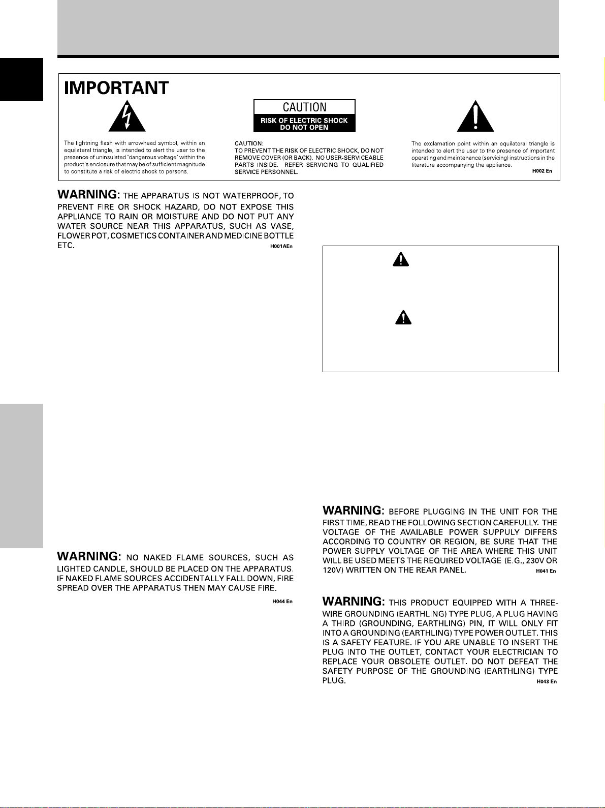
WARNING
This symbol refers to a hazard or unsafe
practice which can result in personal injury
or property damage.
CAUTION
This symbol refers to a hazard or unsafe
practice which can result in severe personal
injury or death.
To ensure proper heat radiation, distance the unit slightly from
other equipment, walls, etc. (normally more than 10 cm). Avoid
the following installations which will block vents and cause heat
to build up inside, resulting in fire hazards.
• Do not attempt to fit the unit inside narrow spaces where
ventilation is poor
• Do not place on carpet
• Do not cover with cloth, etc.
• Do not place on its side
• Do not place it upside down
• If planning special installation such as fitting close to the wall,
Safety Precautions
placing it horizontally, etc., be sure to consult your Pioneer
dealer first.
Operating Environment H045 En
Operating environment temperature and humidity:
0 °C – +40 °C (+32 °F – +104 °F); less than 85 %RH (cooling vents
not blocked)
Do not install in the following locations
÷ Location exposed to direct sunlight or strong artificial light
÷ Location exposed to high humidity, or poorly ventilated
location
ii
i
En
Page 5

Contents
Safety Precautions ........................................................ i
Features ........................................................................ 2
Before Proceeding ........................................................ 3
How to Use This Manual ................................................................ 3
Checking Supplied Accessories ..................................................... 5
Part Names and Functions .......................................... 6
Main Unit ......................................................................................... 6
Remote Control Unit ....................................................................... 7
Connection Panel ............................................................................ 8
Installation and Connections .................................... 10
Installation of the Unit .................................................................. 10
Connection to INPUT1 and INPUT2 ............................................. 12
Audio Connections ....................................................................... 14
Control Cord Connection .............................................................. 15
Power Cord Connection ............................................................... 15
How to Route Cables .................................................................... 16
Setting Up the System .............................................. 17
Setup after Connection ................................................................. 17
English
Operations .................................................................. 19
Selecting an Input Source ............................................................ 19
Screen Size Selection ................................................................... 21
Partial Image Enlargement (POINT ZOOM) ................................ 23
Automatic Power OFF ................................................................... 24
Display Panel Adjustments ....................................... 25
Adjusting the Picture Quality ....................................................... 25
Adjusting the Image Position and Clock
(Automatic Adjustment) ............................................................... 26
Manual Adjustment of Screen Position and Clock ..................... 27
Other Operations ....................................................... 28
Rewriting the Input Display (INPUT LABEL) ............................... 28
Power Control Function ................................................................ 29
AUTO FUNCTION .......................................................................... 29
Audio Output (AUDIO OUT) ......................................................... 30
Additional Information .............................................. 31
Cleaning ......................................................................................... 31
Troubleshooting ............................................................................ 31
Specifications ................................................................................ 34
Supplement 1 ................................................................................ 35
Supplement 2 ................................................................................ 37
Explanation of Terms .................................................................... 37
Before Proceeding
1
En
Page 6

Features
PDP-503MXE PDP-433MXE
English
Introduces newly developed 50" XGA Wide Plasma Panel
The new wide high-precision XGA 50" plasma panel (1280x768 /
16:9) pushes the envelope of previous high-luminance panels,
producing brighter, clearer images with higher contrast.
¶ Newly developed full screen filter produces clear,
high-contrast images even in a lighted room.
The new full screen filter suppresses surface reflections to a
minimum, producing clear, high-contrast images even in lighted
locations. Unnecessary frequency components of RGB signals
are also cut, greatly enhancing color reproduction.
¶ Supports wide range of computer signal formats
Supports non-compressed display of signals ranging from
640x400 and 640x480 (VGA) to 1024x768 (XGA) and 1280x768,
and compressed display of 1280x1024 (SXGA) and 1600x1200
(UXGA) signals. Further, aspect ratio and screen size settings
supported include Dot-by-Dot, 4:3, FULL and PARTIAL*1.
*1 Aspect ratio and screen size appearance will differ depending
on input signal.
¶ Free Installation Configuration
Broader installation possibilities with thinner,
lighter, high-endurance design.
While producing a large 50" screen image, the display is only 98
mm thick, and weighs in at only 38.9 kg. On the other hand, the
efficient heat-radiating design greatly improves environmental
operating conditions. The thinner, lighter design, coupled to highendurance construction greatly broadens the range of possible
installation locations and styles.
¶ High reliability for commercial applications
This display is provided with features giving it high dependability
in commercial applications, including the ability to suppress peak
luminance in accordance with the viewing program, and to
change the cooling fan’s speed in accordance with changes in
operating environment. Such features provide safety and highendurance under conditions of commercial use.
¶ Improved usability
User convenience has been improved by the inclusion of
features making the display even more compatible with your
computer. Some of these include the one-touch screen
adjustment, AUTO SETUP function for computer connections,
and the POINT ZOOM function to enlarge local portions of the
screen image to display important detailed program data.
Before Proceeding
¶ Power-Saving Design
While equipped with a high-precision (1280x768) panel, this unit
achieves the highest energy-saving of any display in its class (50inch XGA class: 380 W; 20% less than previous Pioneer
products). In addition, when the Power Control function is
selected, power consumption is reduced by 20% compared to
the normal operating mode (MODE 1, with color-bar signal input).
¶ Introduces newly developed 43" Wide Plasma Panel
The new wide high-precision 43" plasma panel (1024x768 / 16:9)
pushes the envelope of previous high-luminance panels,
producing brighter, clearer images with higher contrast.
¶ Newly developed full screen filter produces clear,
high-contrast images even in a lighted room.
The new full screen filter suppresses surface reflections to a
minimum, producing clear, high-contrast images even in lighted
locations. Unnecessary frequency components of RGB signals
are also cut, greatly enhancing color reproduction.
¶ Supports wide range of computer signal formats
Supports non-compressed display of signals ranging from
640x400 and 640x480 (VGA) to 1024x768 (XGA), and
compressed display of 1280x1024 (SXGA) and 1600x1200
(UXGA) signals. Further, aspect ratio and screen size settings
supported include Dot-by-Dot, 4:3, and FULL*1.
*1 Aspect ratio and screen size appearance will differ depending
¶ Free Installation Configuration
Broader installation possibilities with thinner,
lighter, high-endurance design.
While producing a large 43" screen image, the display is only 98
mm thick, and weighs in at only 31.5 kg. On the other hand, the
efficient heat-radiating design greatly improves environmental
operating conditions. The thinner, lighter design, coupled to highendurance construction greatly broadens the range of possible
installation locations and styles.
¶ High reliability for commercial applications
This display is provided with features giving it high dependability
in commercial applications, including the ability to suppress peak
luminance in accordance with the viewing program, and to
change the cooling fan’s speed in accordance with changes in
operating environment. Such features provide safety and highendurance under conditions of commercial use.
¶ Improved usability
User convenience has been improved by the inclusion of
features making the display even more compatible with your
computer. Some of these include the one-touch screen
adjustment, AUTO SETUP function for computer connections,
and the POINT ZOOM function to enlarge local portions of the
screen image to display important detailed program data.
¶ Power-Saving Design
While equipped with a high-precision (1024x768) panel, this unit
achieves the highest energy-saving of any display in its class (43inch class: 298 W). In addition, when the Power Control function
is selected, power consumption is reduced by 20% compared to
the normal operating mode (MODE 1, with color-bar signal input).
on input signal.
¶ Optional line (sold separately)
(For details, please consult the dealer where this unit was
purchased.)
1 Table top stand: PDP-503MXE / PDP-433MXE display stand.
2 Wall installation unit: Wall installation bracket designed as a
3
Speaker system designed specifically for plasma displays
(width: 7.4 cm): With the adoption of a vertical 2-way system
wall interface for securing the unit.
designed with a 2.5 cm domed conical tweeter and
newly developed 4.5 cm wide oval shaped units
arranged vertically. (When speakers are attached,
the operation panel on this unit is not operable.)
2
En
4 Video card: Expansion card allows viewing of video signals
and computer digital RGB signals (DVI compliant).
5 Cable cover: Dedicated cover to allow fashionable concealment
of rear cable connections.
Page 7
Before Proceeding
How to Use This Manual
This manual is set up to follow the course of actions and
operations in the order that would seem most logical for
someone setting up this unit.
Once the unit has been taken out of the box and it has
been confirmed that all the parts have been received, it
may be beneficial to look over the section “Part Names
and Functions” starting on page 6 to become acquainted
with the plasma monitor and remote control unit, as their
respective buttons and controls will be referred to
throughout this manual.
The section “Installation and Connections” starting on
page 10 covers all the necessary points regarding
installation of the plasma display and connections to a
wide variety of components.
The section “Setting Up the System” starting on page 17
covers the necessary on-screen menu settings to
establish correct linkage between the plasma display and
connected components. Depending on the connections
made, this section may or may not be necessary.
The remainder of the sections in this manual is dedicated
to the basic operations associated with selecting a source
component up to the more complex operations
associated with adjusting the plasma display picture to
match the requirements of specific components and
personal preferences.
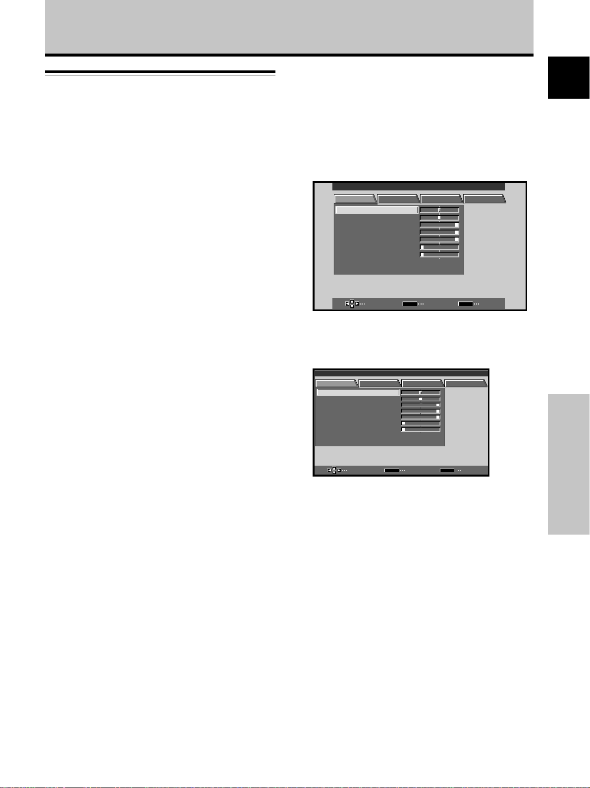
Screen Displays
The example screen displays provided in this manual are
those for the PDP-503MXE model. The PDP-433MXE
display differs as shown:
Example of PDP-503MXE Screen Display:
÷ The PDP-503MXE screen display has a non-
displaying border at each side of the display.
MAIN MENU INPUT1
PICTURE SCREEN SET UP OPTION
CONT RAS T
BR
IGHT.
RLEVEL
.
GLEVEL.
BLEVEL.
H E NHANCE.
V E NH ANCE.
RSETE
SELECT ENTER EXIT
Example of PDP-433MXE Screen Display:
÷ The PDP-433MXE screen display fills the display area in
both horizontal directions.
MAIN MENU INPUT1
PICTURE SCREEN SET UP OPTION
CONT RAS T
BR
IGHT.
RLEVEL
.
GLEVEL.
BLEVEL.
H ENH ANCE.
V E NHAN CE.
RSETE
:
0
:
0
:
+
6
0
:
+
60
:
+
60
:
0
:
0
SET
:
0
:
0
:
+
0
6
:
+
60
:
+
60
:
0
:
0
MENU
English
SELECT ENTER EXIT
SET
MENU
Please note that the actual contents displayed are the
same for both the PDP-503MXE and PDP-433MXE.
Before Proceeding
3
En
Page 8
Before Proceeding
About operations in this manual
English
Operations in this manual are outlined in step by step
numbered procedures. Most of the procedures are
written in reference to the remote control unit unless the
button or control is only present on the main unit.
However, if a button or control on the main unit has the
same or similar name as that on the remote control unit,
that button can be used when performing operations.
The following example is an actual operation that shows
how one might set the horizontal and vertical positions of
the screen. The screens shown at each step are provided
as a visual guide to confirm that the procedure is
proceeding as it should. Please familiarize yourself with
this process before continuing on with the rest of this
manual.
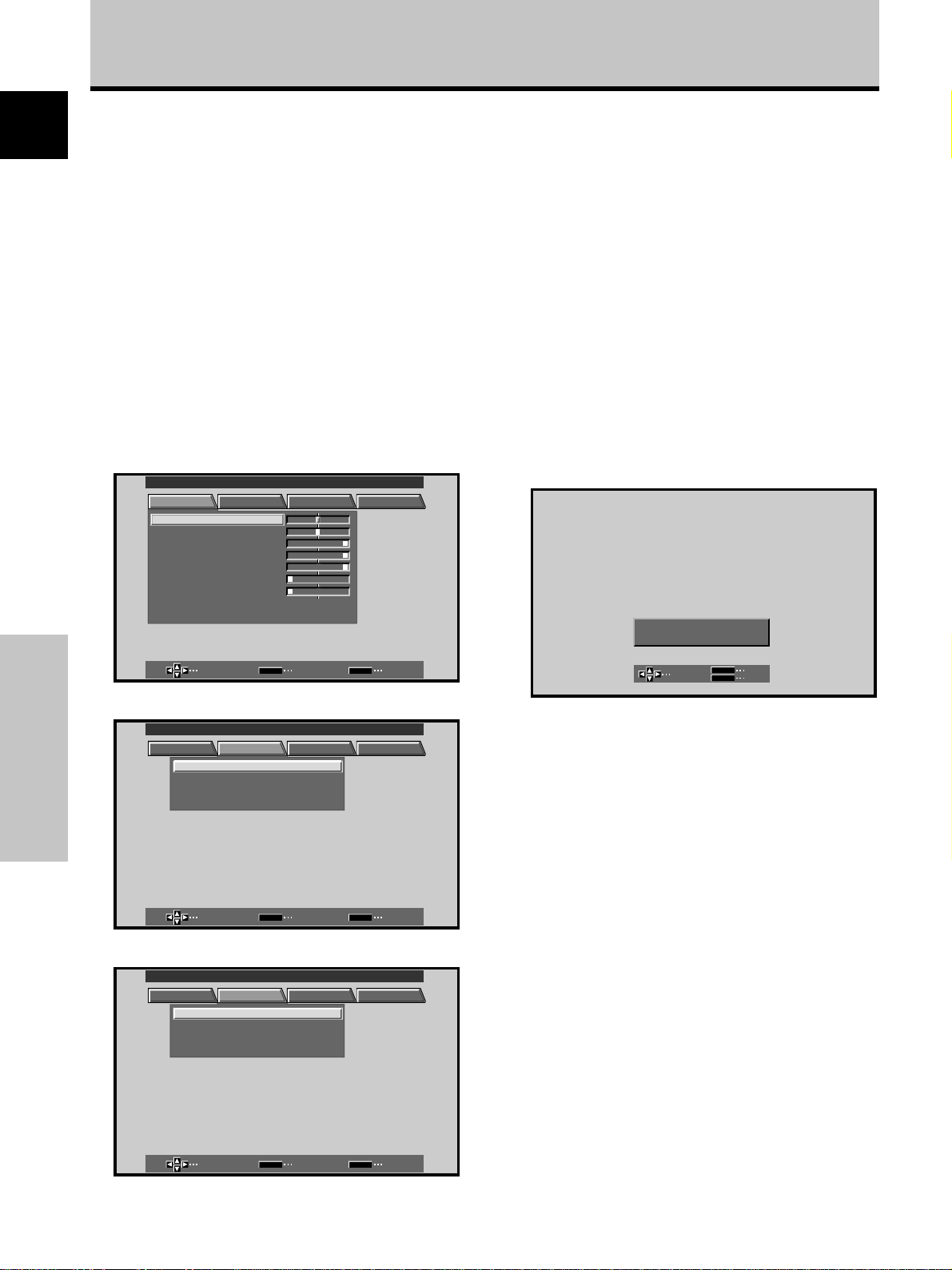
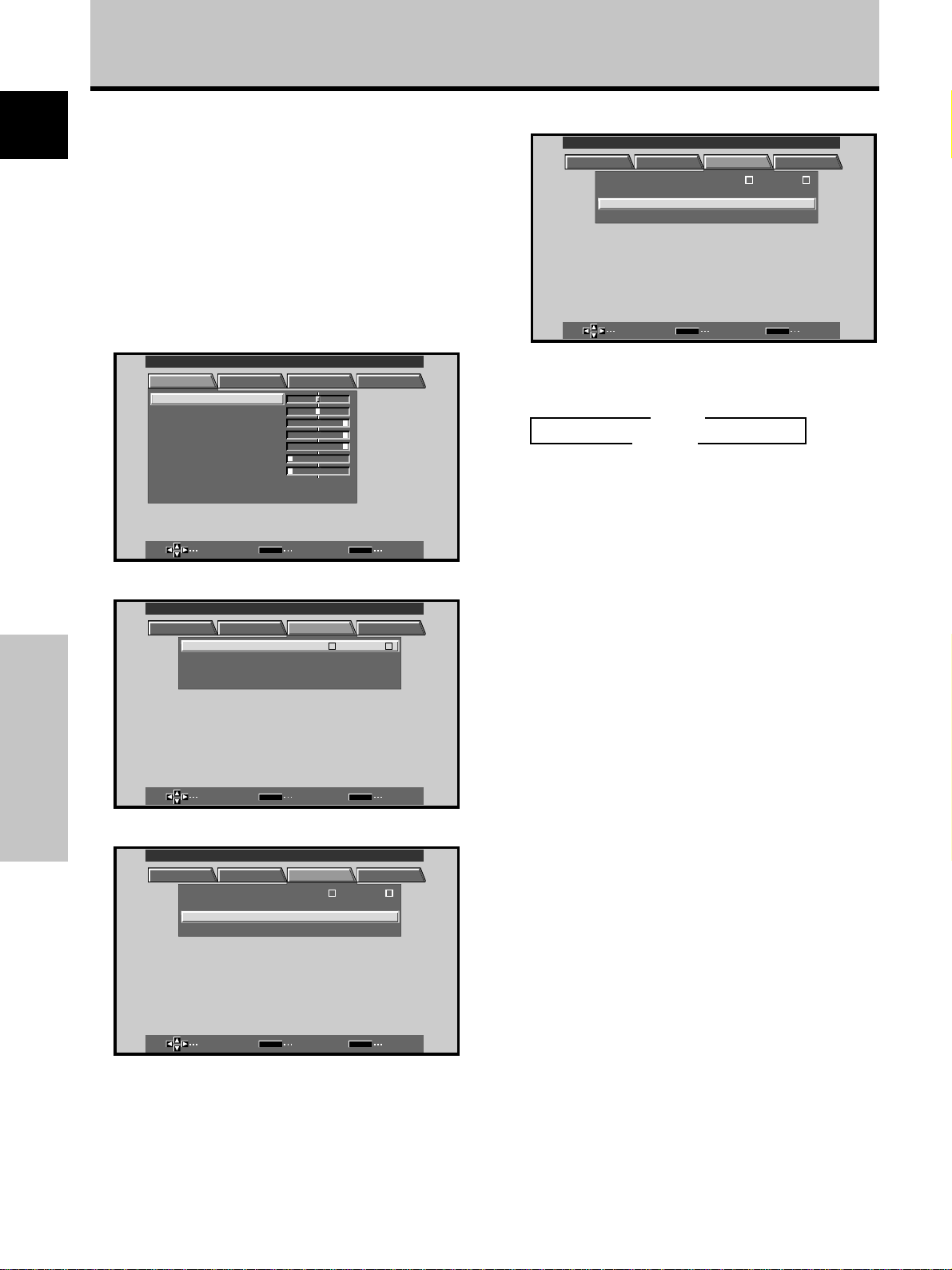
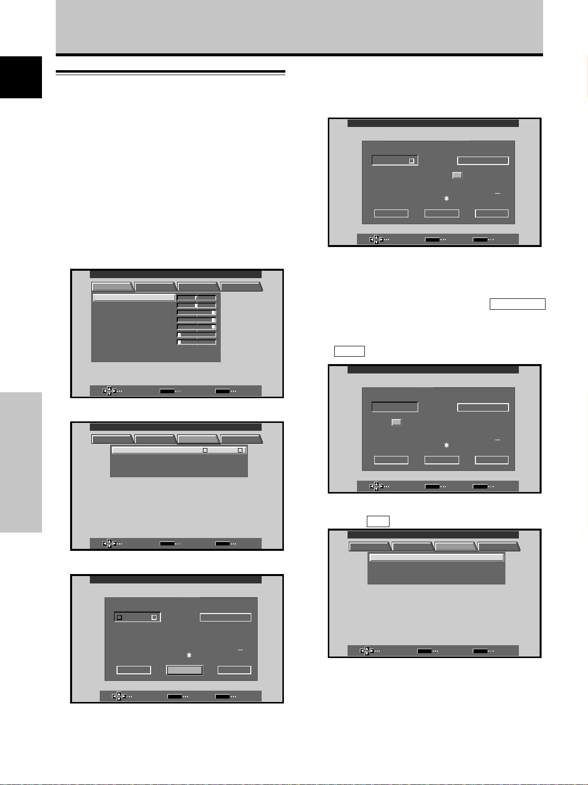
1 Press MENU to display the menu screen.
MAIN MENU INPUT1
PICTURE SCREEN SET UP OPTION
CONT RAS T
BR
IGHT.
RLEVEL
.
GLEVEL.
BLEVEL.
H E NHANCE.
V E NH ANCE.
RSETE
SELECT ENTER EXIT
:
0
:
0
:
+
6
0
:
+
60
:
+
60
:
0
:
0
SET
2 Press 3 to select SCREEN.
MAIN MENU INPUT1
PICTURE SCREEN SET UP OPTION
:
00
/
:
P
00
SET
Before Proceeding
POS I T I ON
CL OC HASEK/ /
RSETE
SELECT ENTER EXIT
MENU
MENU
4 Press SET to display the adjustment screen for the
selected item.
MENU
SET
:
0
:
0
EXIT
SET
POH. S I T I ON
POV. S I T I ON
ADJUST
5 Press 5/∞/2/3 to adjust the value.
Note
The screen displays depicted in this manual represent typical
display examples.
The actual items and contents seen in screen displays may vary
depending on input source and specific settings.
3 Press 5/∞ to select the item to be adjusted.
MAIN MENU INPUT1
PICTURE SCREEN SET UP OPTION
POS I T I ON
CL OC HASEK/ /
RSETE
SELECT ENTER EXIT
:
00
/
:
P
SET
00
MENU
4
En
Page 9
Before Proceeding
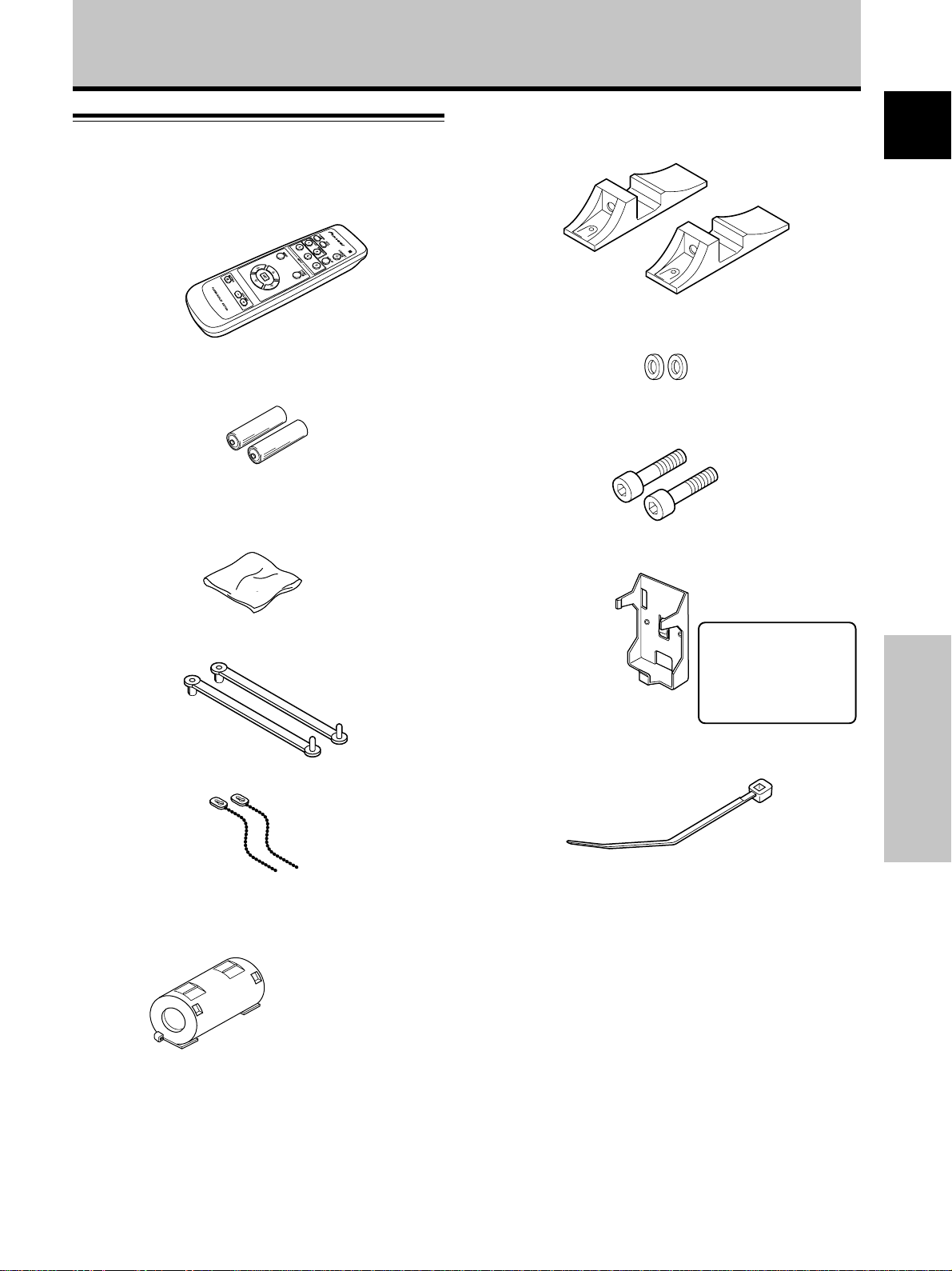
Checking Supplied Accessories
Check that the following accessories were supplied.
1 Remote control unit
2 AA (R6) batteries (x 2)
3 Cleaning cloth (for wiping front panel)
7 Display stands (x 2)
8 Washers (x 2)
9 Hex hole bolts (x 2)
0 Remote control unit holder
English
4 Speed clamps (x 2)
5 Bead bands (x 2)
6 Ferrite core
Use as a holder for the
remote control unit.
When attaching to the
rear of the main unit,
be careful not to cover
the vents.
- Cable tie
Before Proceeding
÷ Operating Instructions
5
En
Page 10
Part Names and Functions
English
Main Unit
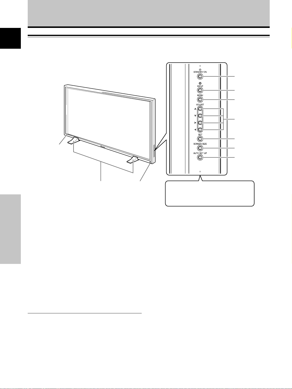
Operation panel on the main unit
Main unit
3
1
2
4
5
6
7
8
9
0
Note
When optional speakers have been connected,
the operation panel on the main unit will not be
operable.
Main unit
1 Display stand
2 Remote control sensor
Part Names and Functions
Point the remote control toward the remote sensor to
operate the unit (page 8).
3 STANDBY/ON indicator
This indicator is red during standby mode, and turns
to green when the unit is in the operation mode
(page 19).
Flashes green when Power-Management function is
operating (page 24).
The flashing pattern is also used to indicate error
messages (page 33).
Operation panel on the main unit
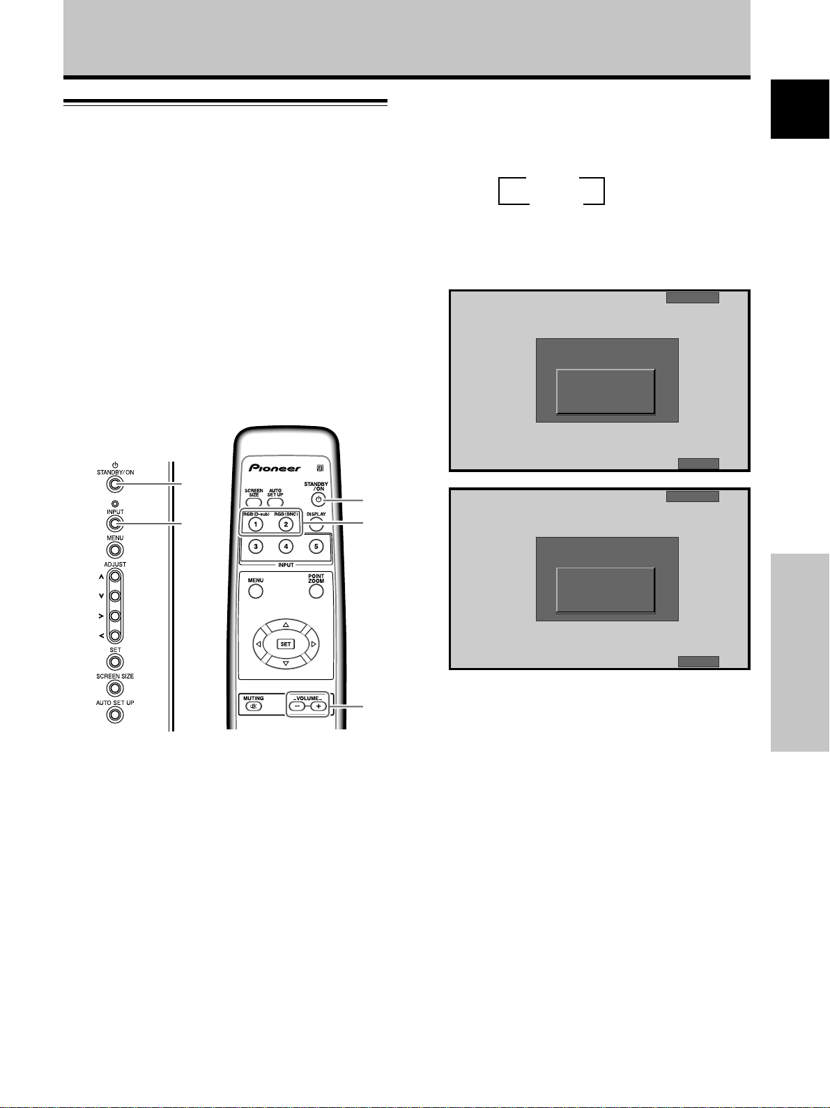
4 STANDBY/ON button
Press to put the display in operation or standby mode
(page 19).
5 INPUT button
Press to select input (page 19).
6 MENU button
Press to open and close the on-screen menu (pages
17 to 30).
7 ADJUST (5/∞/3/2) buttons
Use to navigate menu screens and to adjust various
settings on the unit.
Usage of cursor buttons within operations is clearly
indicated in the on-screen display (pages 17 to 30).
8 SET button
Press to adjust or enter various settings on the unit
(pages 17 to 30).
9 SCREEN SIZE button
Press to select the screen size (page 21).
0 AUTO SET UP button
When using computer signal input, automatically sets
the POSITION and CLOCK/PHASE to optimum values
(page 26).
6
En
Page 11
Part Names and Functions
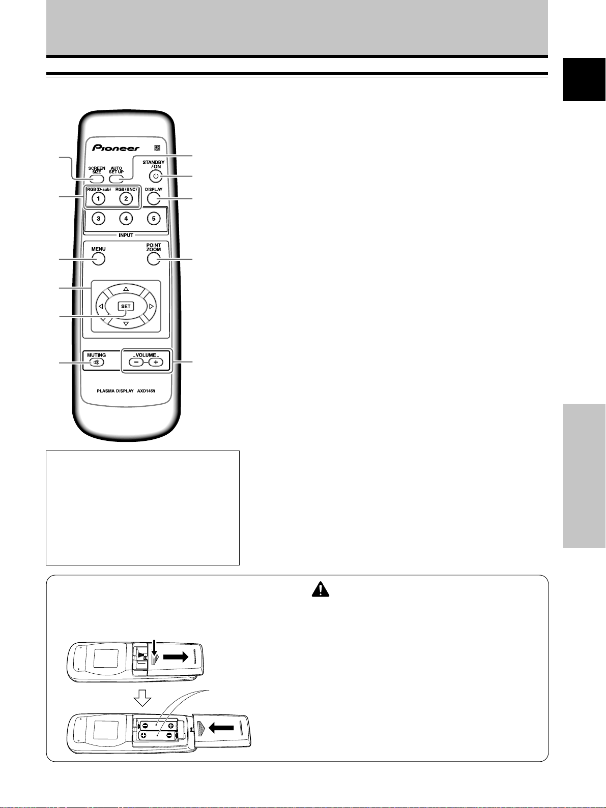
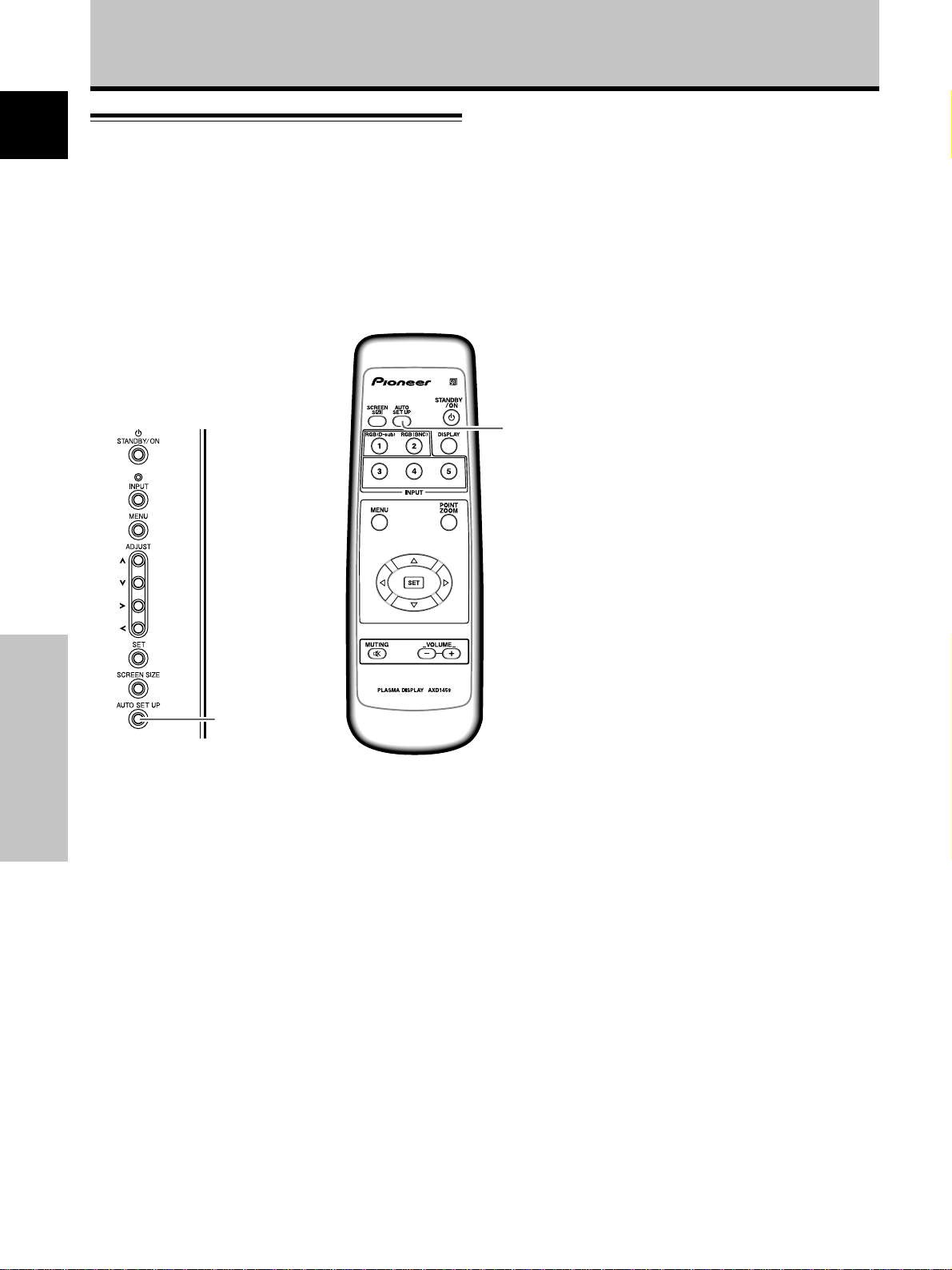
Remote Control Unit
1
2
3
4
5
6
7
8
9
0
-
English
1 SCREEN SIZE button
Press to select the screen size (page 21).
2 INPUT buttons
Use to select the input (page 19).
3 MENU button
Press to open and close the on-screen menu
(pages 17 to 30).
4 ADJUST (5/∞/3/2) buttons
Use to navigate menu screens and to adjust various settings on the
unit.
Usage of cursor buttons within operations is clearly indicated at the
bottom the on-screen menu display (pages 17 to 30).
5 SET button
Press to adjust or enter various settings on the unit (pages 17 to 30).
6 MUTING button
Press to mute the volume (page 20).
7 AUTO SET UP button
When using computer signal input, automatically sets the POSITION
and CLOCK/ PHASE to optimum values (page 26).
When handling the remote control unit
¶ Do not drop or shake the remote control.
¶ Do not use the remote control unit in a location
subject to direct sunlight, heat radiation from a
heater, or in a place subject to excessive
humidity.
¶ When the remote control unit’s batteries begin
to wear out, the operable distance will gradually
become shorter. When this occurs, replace all
batteries with new ones as soon as possible.
Inserting the batteries in the
remote control unit
While pressing down lightly, slide
in the direction of the arrow.
Two AA (R6)
batteries
8 STANDBY/ON button
Press to put the unit in operation or standby mode (page 19).
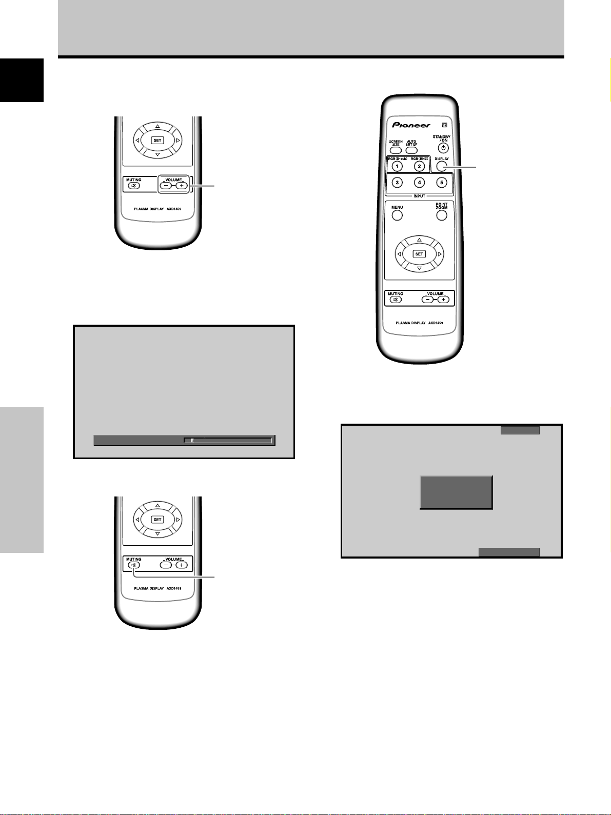
9 DISPLAY button
Press to view the unit’s current input and setup mode (page 20).
0 POINT ZOOM button
Use to select and enlarge one part of the screen (page 23).
- VOLUME (+/–) buttons
Use to adjust the volume (page 20).
CAUTION
¶ Insert batteries so that the plus (+) and minus (–) sides are
aligned according to the markings in the battery case.
¶ Do not mix new batteries with used ones.
¶ The voltage of batteries may differ even if they are the same
shape. Please do not mix different kinds of batteries
together.
¶ When not using the remote control unit for a long period of
time (1 month or more), remove the batteries from the
remote control unit to prevent leaking of battery fluid. If
battery liquid has leaked, thoroughly wipe the inside of the
case until all liquid is removed, and then insert new batteries.
¶ Do not charge, short, disassemble or throw the provided
batteries in a fire.
When disposing of used batteries, please comply with
governmental regulations or environmental public
instruction’s rules that apply in your country or area. H048 En
Part Names and Functions
7
En
Page 12
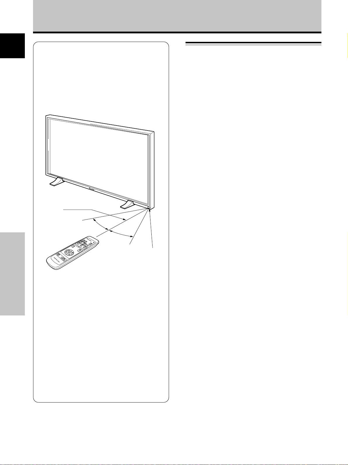
Part Names and Functions
Operating range of the remote
English
control unit
When operating the remote control unit, point it at the
remote sensor (Î) located on the front panel of the
main unit. The remote control unit is operable up to 7 m
from the unit and within a 30 angle on each side of the
sensor.
Connection Panel
The connection panel is provided with two video input
terminals and one video output terminal. Audio input and
speaker output terminals are also provided, together with
a CONTROL IN/OUT connector for connecting to
PIONEER components bearing the Î mark.
For instructions regarding connections, consult the pages
noted in parentheses by each item.
1 SPEAKER (R) terminal
For connection of an external right speaker.
Connect a speaker that has an impedance of 8 -16 Ω
(page 14).
2 CONTROL IN/OUT (monaural mini jacks)
For connection of PIONEER components that bear the
Î mark. Making CONTROL connection enables
control of this unit as a component in a system
(page 15).
7 m
30°
30°
If you are having difficulty with operation of
the remote control unit
¶ The remote control unit may not operate if there are
Part Names and Functions
objects placed between it and the display.
¶ Operational distance will gradually become shorter as the
batteries begin to wear out, replace weak batteries with
new ones as soon as possible.
¶ This unit discharges infrared rays from the screen. Placing a
video deck or other component that is operated by an
infrared remote control unit near this unit may hamper that
component’s reception of the remote control’s signal, or
prevent it from receiving the signal entirely. Should this
occur, move the component to a position further away from
this unit.
¶ Depending on the installation surroundings, this unit’s
remote control unit may be influenced by the infrared rays
discharged from the plasma display, hampering reception of
its rays or limiting its operational distance. The strength of
infrared rays discharged from the screen will differ
according to the picture displayed.
Remote Sensor
3 COMBINATION IN/OUT
DO NOT MAKE ANY CONNECTIONS TO THESE
TERMINALS.
These terminals are used in the factory setup.
4 RS-232C
DO NOT MAKE ANY CONNECTIONS TO THIS
TERMINAL.
This terminal is used in the factory setup.
5 INPUT1 (mini D-sub 15 pin)
For connection of a personal computer (PC) or similar
component. Make sure that the connection made
corresponds to the format of the signal output from
the connected component (pages 12 to 14).
6 OUTPUT (INPUT1) (mini D-sub 15 pin)
Use the OUTPUT (INPUT1) terminal to output the
video signal to an external monitor or other
component.
Note: The video signal will not be output from the
OUTPUT (INPUT1) terminal when the main power of
this unit is off or in standby mode.
(page 13)
7 INPUT2 (BNC jacks)
For connection of a personal computer (PC) or similar
component. Make sure that the connection made
corresponds to the format of the signal output from
the connected component (pages 12 to 14).
8
En
Page 13
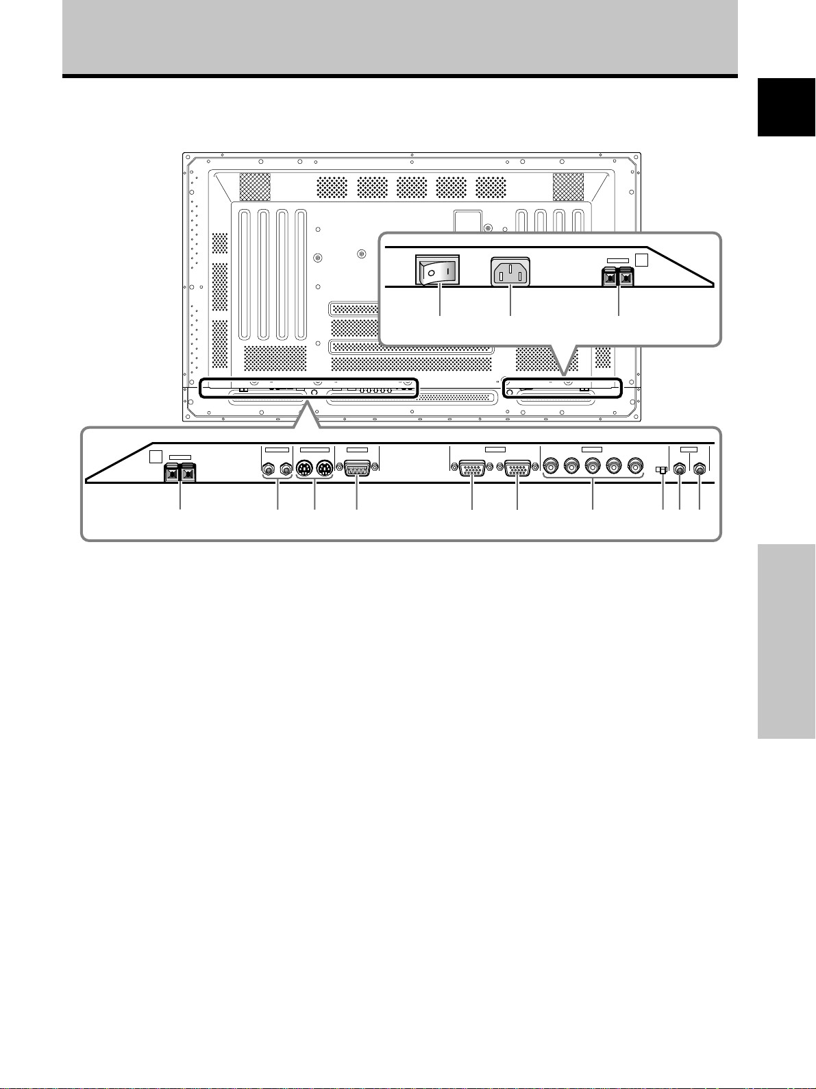
Illustration depicts PDP-503MXE model.
Part Names and Functions
English
COMBINATION
8Ω ~16Ω
SPEAKER
R
+ –
1
CONTROL
IN OUT
IN OUT
23 4
RS-232C
8 Synchronizing signal impedance selector switch
Depending on the connections made at INPUT2, it
may be necessary to set this switch to match the
output impedance of the connected component’s
synchronization signal.
When the output impedance of the component’s
synchronization signal is below 75 Ω, set this switch
to the 75 Ω position (pages 12, 14).
9 AUDIO INPUT (Stereo mini jack)
Use to obtain sound when INPUT1 or INPUT2 is
selected.
Connect the audio output jack of components
connected to INPUT1 or INPUT2 to this unit (page 14).
AC INLET
8Ω ~16Ω
SPEAKER
+ –
L
~=-
INPUT1
ANALOG RGB (ANALOG RGB)
5 678
(ON SYNC) (H/V SYNC)
OUTPUT
GBRHDVD
INPUT2 AUDIO
75 2.2
Ω kΩ
INPUT
(INPUT1/2)
Ô
9
- MAIN POWER switch
Use to switch the main power of the unit on and off.
= AC INLET
Use to connect a power cord to an AC outlet (page
15).
~ SPEAKER (L) terminal
For connection of an external left speaker. Connect a
speaker that has an impedance of 8 -16 Ω (page 14).
OUTPUT
0
Part Names and Functions
0 AUDIO OUTPUT (Stereo mini jack)
Use to output the audio of the selected source
component connected to this unit to an AV amplifier
or similar component (page 14).
9
En
Page 14
Installation and Connections
English
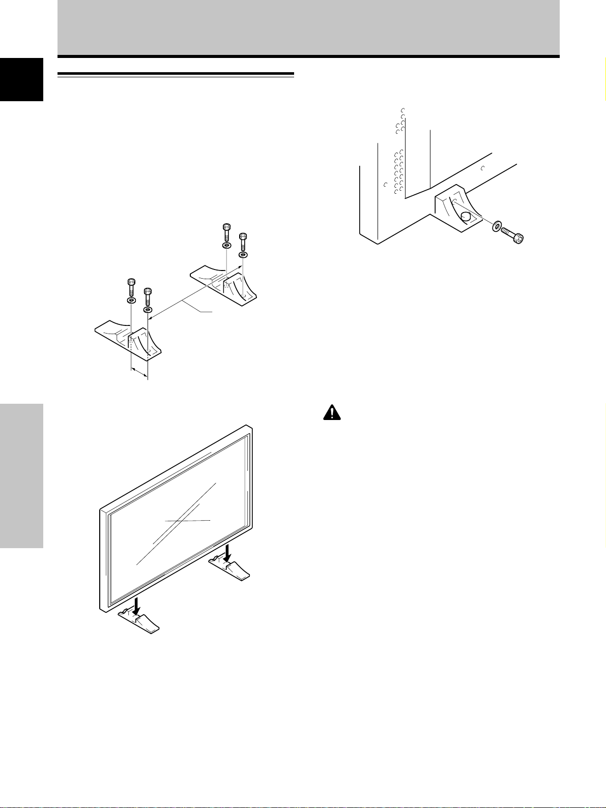
Installation of the Unit
Installation using the supplied display stand
Be sure to fix the supplied stand to the installation
surface.
Use commercially available M8 bolts that are 25 mm
longer than the thickness of the installation surface.
1 Fix the supplied stand to the installation surface at
each of the 4 prepared holes using commercially
available M8 bolts .
Front
PDP-503MXE: 798 mm
PDP-433MXE: 768 mm
Rear
3 Fix this unit using the supplied washer and bolt.
Use a 6 mm hex wrench
to bolt them.
110 mm
2 Set this unit in the stand.
Installation and Connections
CAUTION
This display unit weighs at least 30 kg and has little front-to-back
depth, making it very unstable when stood on edge. As a result,
two or more persons should cooperate when unpacking, moving,
or installing the display.
10
En
Page 15
Installation and Connections
Installation using the optional PIONEER stand or
installation bracket
÷ Please be sure to request installation or mounting of this unit
or the installation bracket by an installation specialist or the
dealer where purchased.
÷ When installing, be sure to use the bolts provided with the
stand or installation bracket.
÷ For details concerning installation, please refer to the
instruction manual provided with the stand or installation
bracket.
Installation using accessories other than the
PIONEER stand or installation bracket (sold
separately)
÷ When possible, please install using parts and accessories
manufactured by PIONEER. PIONEER will not be held
responsible for accident or damage caused by the use of parts
and accessories manufactured by other companies.
÷ For custom installation, please consult the dealer where the
unit was purchased, or a qualified installer.
Air vents (fan)
b hole
b hole
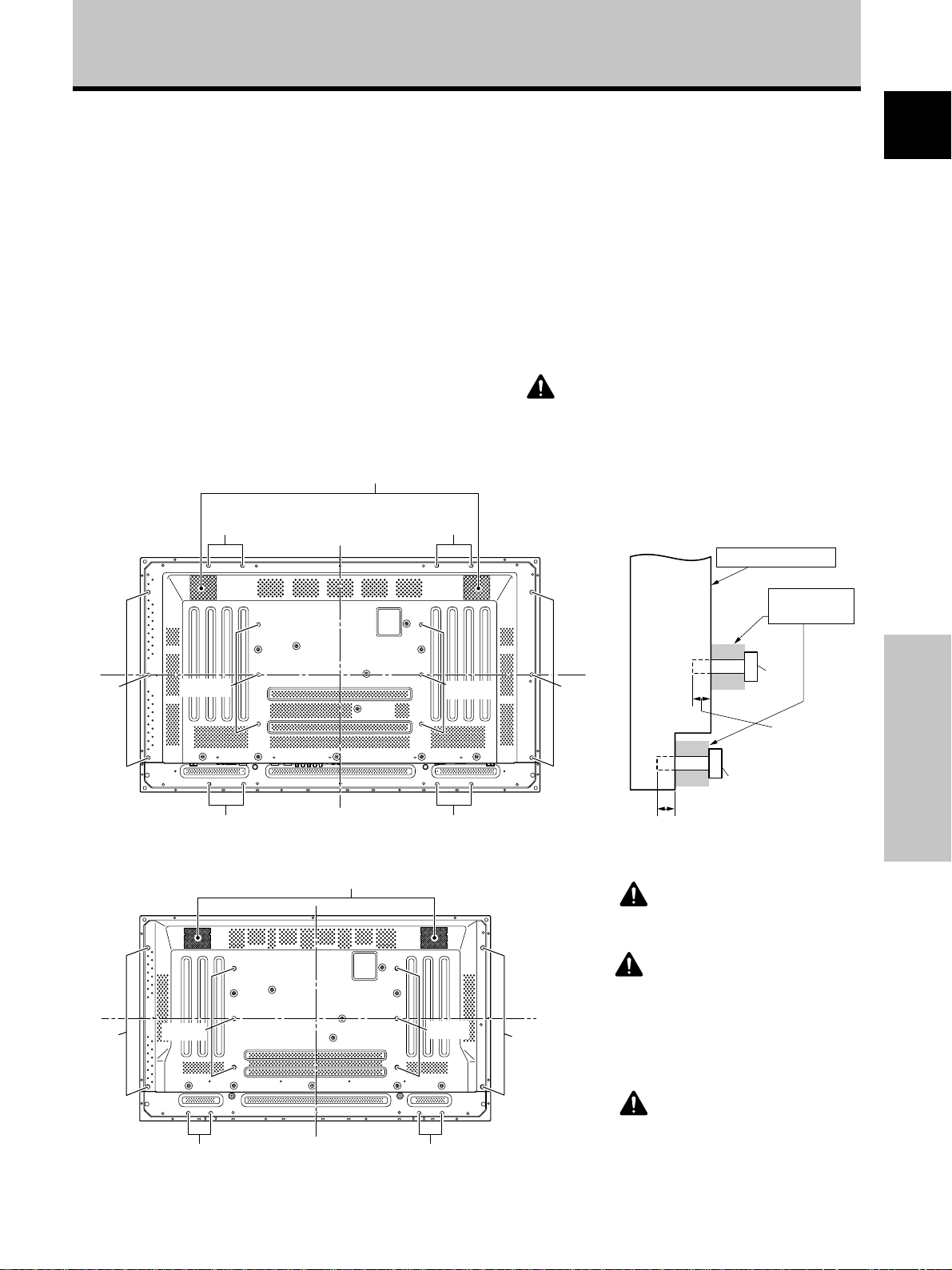
Wall-mount installation of the unit
This unit has been designed with bolt holes for
wall-mount installation, etc. The installation holes that can
be used are shown in the diagram below.
÷ Be sure to attach in 4 or more locations above and
below, left and right of the center line.
÷ Use bolts that are long enough to be inserted 12 mm to
18 mm into the main unit from the attaching surface for
both a holes and b holes. Refer to the side view
diagram below.
÷ As this unit is constructed with glass, be sure to install
it on a flat, unwarped surface.
CAUTION
To avoid malfunction, overheating of this unit, and possible
fire hazard, make sure that the vents on the main unit are
not blocked when installing. Also, as hot air is expelled
from the air vents, be careful of deterioration and dirt build
up on rear surface wall, etc..
Attaching surface
English
Français
b hole
b hole
a hole
Center line
Rear view diagram (PDP-503MXE)
Air vents (fan)
a hole
a hole
b holeb hole
a hole
Center line
Center line
b hole
b hole
Installation
bracket, etc..
Main unit
b hole
12 mm to 18 mm
a hole
Bolt
12 mm to 18 mm
Bolt
Side view diagram
CAUTION
Please be sure to use an M8 (Pitch = 1.25
mm) bolt. (Only this size bolt can be used.)
CAUTION
This display unit weighs at least 30 kg and
has little front-to-back depth, making it very
unstable when stood on edge. As a result,
two or more persons should cooperate
when unpacking, moving, or installing the
display.
Installation and Connections
Center line
b holeb hole
Rear view diagram (PDP-433MXE)
CAUTION
This unit incorporates a thin design. To
ensure safety if vibrated or shaken, please
be sure to take measures to prevent the
unit from tipping over.
11
En
Page 16
Installation and Connections
English
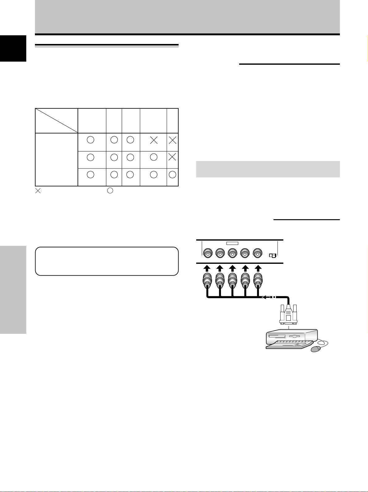
Connection to INPUT1 and INPUT2
The INPUT 1 and INPUT 2 terminals are used to connect
the display to a computer. After making the connections,
adjust the screen settings in accordance with the
computer’s signal output. See pages 17-18 for information
regarding settings.
INPUT2
Output
source
Personal
computer (PC)
with RGB output
: Do not connect anything. : Connect to this jack.
Note
Components compatible with INPUT1 are also compatible with
INPUT2.
INPUT1 is compatible with Microsoft’s Plug & Play (VESA DDC
1/2B).
When making connections to INPUT1, please refer to
supplement 2 on page 37.
jack
[ON SYNC]
GBR
SYNC ON G
GBR
R
B
RG
B
[H/V SYNC]
For the screen sizes and input signals that
INPUT1 and INPUT2 are compatible with, please
refer to supplement 1 (pages 35 and 36).
HD VD
H/V SYNC
HD
VD
Connection to a personal
computer
Connection method differs depending on the computer
type. When connecting, please thoroughly read the
computer’s instruction manual.
Before making connections, be sure to make sure that
the personal computer’s power and this unit’s main
power is off.
For the PC input signals and screen sizes that this unit is
compatible with, please refer to supplement 1 (pages 35
and 36).
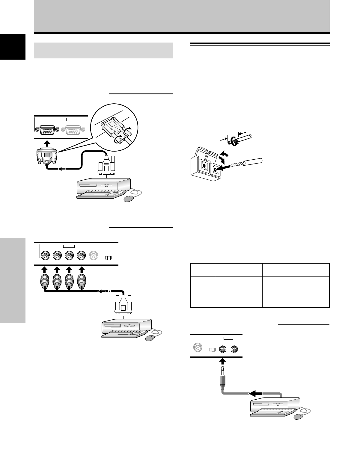
Connection of separate SYNC analog RGB
source
Make separate SYNC connections for a personal
computer that has RGB output separated into 5 output
signals: green, blue, red, horizontal synchronization signal,
and vertical synchronization signal.
When connecting to INPUT2
(ON SYNC) (H/V SYNC)
GBRHDVD
INPUT2
75 2.2
Ô
Ω kΩ
Installation and Connections
12
En
When using INPUT2, set the impedance selector switch
to match the output impedance of the connected
computer’s synchronization signal.
When the output impedance of the computer’s
synchronization signal is below 75 Ω, set this switch to
the 75 Ω position.
On-screen setup is necessary after connection.
Please see pages 17 and 18.
Page 17
Installation and Connections
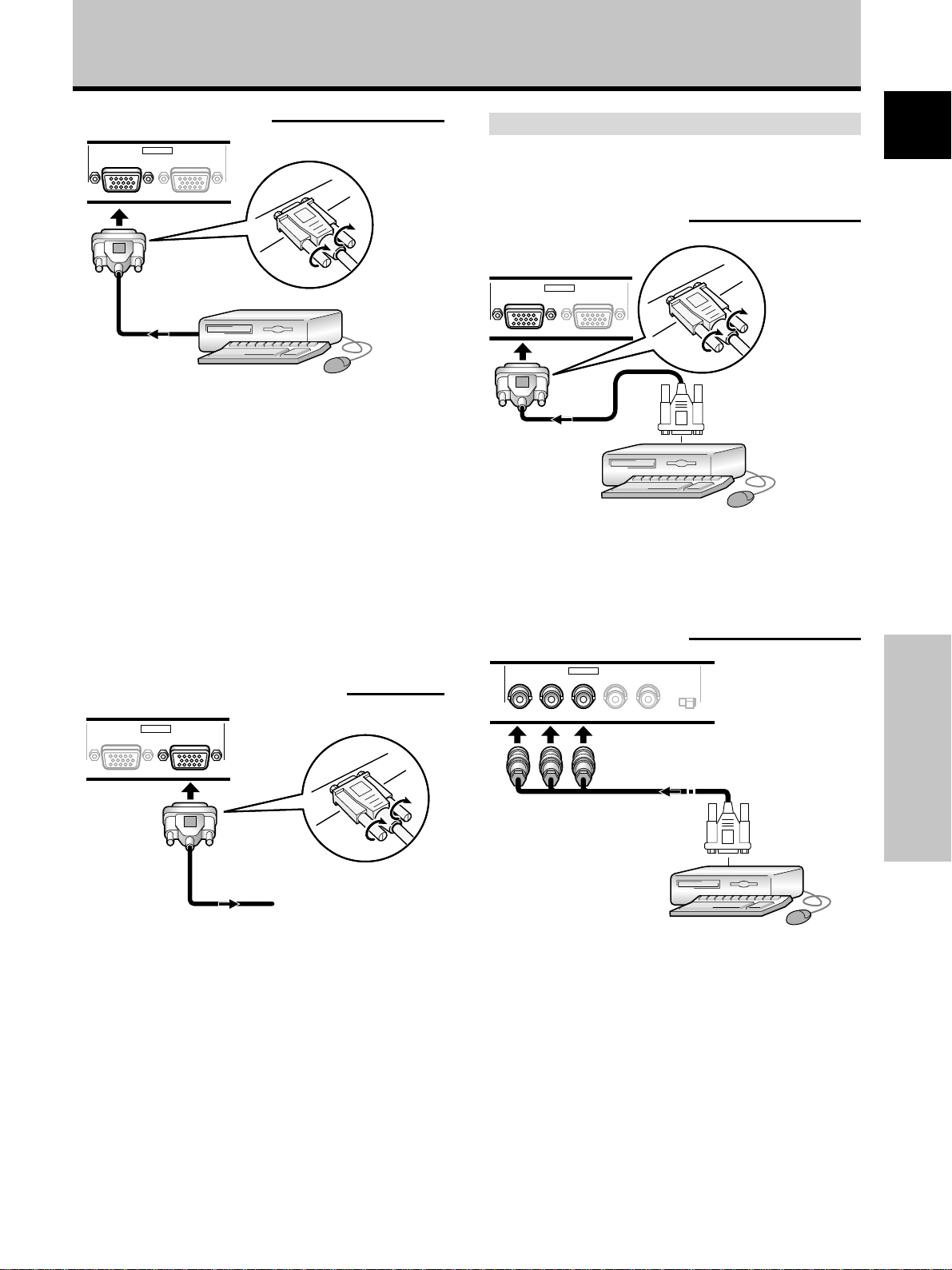
When connecting to INPUT1
INPUT1
ANALOG RGB (ANALOG RGB)
OUTPUT
Connect the cable corresponding to the shape of the
input terminal on this unit and the personal computer’s
output terminal.
Secure by tightening the terminal screws on both units.
After connecting, on-screen setup is necessary.
Please see pages 17 and 18.
Note
Depending on the type of computer model being connected, a
conversion connector or adapter etc. provided with the computer
or sold separately may be necessary.
For details, please read your PC’s instruction manual or consult
the maker or nearest dealer of your computer.
When connecting to OUTPUT (INPUT1)
Connection of SYNC ON G analog RGB source
Make SYNC ON G connections for a personal computer
with output that has the synchronization signal layered on
top of the green signal.
When connecting to INPUT1
INPUT1
ANALOG RGB (ANALOG RGB)
On screen setup is necessary after connection.
Please see pages 17 and 18.
When connecting to INPUT2
(ON SYNC) (H/V SYNC)
GBRHD VD
OUTPUT
INPUT2
75 2.2
Ô
Ω kΩ
English
Français
INPUT1
ANALOG RGB (ANALOG RGB)
OUTPUT
To an external monitor
With this unit, it is possible to output the video signal to
an external monitor or other component from the
OUTPUT (INPUT1) terminal.
Note
A video signal will not be output from the OUTPUT (INPUT1)
terminal when the main power of this unit is off or in standby.
Installation and Connections
On screen setup is necessary after connection.
Please see pages 17 and 18.
Note
When making SYNC ON G connections, do not make any
connections to the VD or HD terminals. If connections are made,
the picture may be not displayed normally.
13
En
Page 18
Installation and Connections
10 mm
Connection of composite SYNC analog RGB
English
source
Make composite SYNC connections for a personal
computer with output that has the vertical
synchronization signal layered on top of the horizontal
synchronization signal.
When connecting to INPUT1
INPUT1
ANALOG RGB (ANALOG RGB)
On-screen setup is necessary after connection.
Please see pages 17 and 18.
OUTPUT
Audio Connections
Before making connections, be sure to check that the
audio component’s power and the unit’s main power is
off.
Connecting the speakers
This unit is equipped with speaker output terminals for
connection to the speaker system (not supplied) specially
designed for use with this unit. Refer to the illustrations
below when making connections to the speaker terminals
on this unit.
Twist exposed
wire strands
together.
Push tab to the open
position, and insert the
wire. Then, close tab
firmly to secure the wire
in place.
Note
When making speaker connections, be sure to match the
polarities (+ and –) of the speaker terminals on this unit and the
corresponding terminals on the speakers. If the polarity is
reversed, the sound will be unnatural and lack bass.
When connecting to INPUT2
(ON SYNC) (H/V SYNC)
GBRHDVD
INPUT2
75 2.2
Ô
Ω kΩ
Installation and Connections
When using INPUT2, set the impedance selector switch
to match the output impedance of the connected
computer’s synchronization signal.
When the output impedance of the computer’s
synchronization signal is below 75 Ω, set this switch to
the 75 Ω position.
On-screen setup is necessary after connection.
Please see pages 17 and 18.
Notes
÷ When making composite SYNC connections, do not connect
anything to the VD jack. If connected, the picture may not be
displayed properly.
÷ On some types of Macintosh® components, SYNC ON G and
composite SYNC are both output. With this type of
component, please connect using the SYNC ON G connection
(see page 13).
14
En
Making connections to the audio inputs on this
unit
This unit features two audio inputs and one audio output.
The following chart shows the video inputs and the
corresponding audio input terminals.
Video
input
INPUT1
INPUT2
Audio connections for component (computer)
connected to INPUT 1 or INPUT 2
VD
Audio input to the
AUDIO INPUT terminals
(stereo mini jack) is
possible for a
component connected to either INPUT1 or INPUT2.
Sound is output from both the AUDIO OUTPUT jacks
(stereo mini jack) and the SPEAKER terminals according
to the video input selection.
Audio input jacks Sound output
Sound of the selected video
Stereo mini jack
(L/R)
input is output from the
• SPEAKER terminals
• Stereo mini jacks (L/R).
AUDIO
INPUT
OUTPUT
(INPUT1/2)
75 2.2
Ô
Ω kΩ
Page 19
Installation and Connections
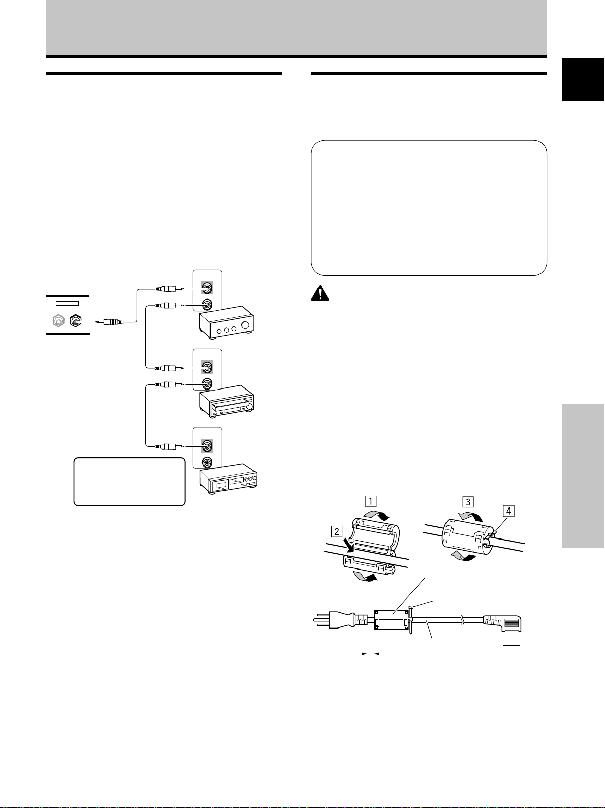
Control Cord Connection
When control cord connections are made, remote control
operation of connected PIONEER components that bear
the Î logo mark is done through the remote sensor on
this unit.
When the connection is made to the CONTROL IN
terminal on another unit, the remote sensor of that
component will no longer receive signals. Point the
remote control unit of the connected component at the
remote control sensor on this unit to control.
Notes
÷ Make sure the power is turned off when making
connections.
÷ Please complete all component connections before
making control cord connections.
Main unit
CONTROL
IN OUT
CONTROL
IN
OUT
CONTROL
IN
OUT
Power Cord Connection
Connect a power cord after all component connections
have been completed.
PDP-503MXE / PDP-433MXE power cord ratings
Cord .......................... Cross-sectional area 3 x 1.0 mm
(According to CEE 13)
Connector ................................................... 10 A, 250 V
(According to EN60320 Sheet C13)
Plug ................................ International use (10 A, 250 V)
Example:
UK : UK 13 Amp Plug with rated 13 Amp fuse
(According to BS1363)
EURO : 10 A/16 A 250 V (According to CEE 7, 1 V)
CAUTION
÷ Do not use a power supply voltage other than that indicated
(AC 100 - 240 V, 50/60 Hz) as this may cause fire or electric
shock.
÷ For the plasma display, a three-core power cord with a ground
terminal is used for efficiency protection. Always be sure to
connect the power cord to a three-pronged grounded outlet
and make sure that the cord is properly grounded. If you use a
power source converter plug, use an outlet with a ground
terminal and screw down the ground line.
English
2
Français
The control cables (not
supplied) are monaural
cables with mini plugs (no
resistance).
CONTROL
IN
OUT
Attaching the Ferrite Core
To help prevent noise, attach the accessory ferrite core to
the plug end of the power cord as shown in the
accompanying illustration. Use the provided cable tie to
prevent the ferrite core from slipping on the cable.
Ferrite core
Cable tie
To power
outlet
As close as possible
AC power cord
To AC INLET
Installation and Connections
15
En
Page 20
Installation and Connections
English
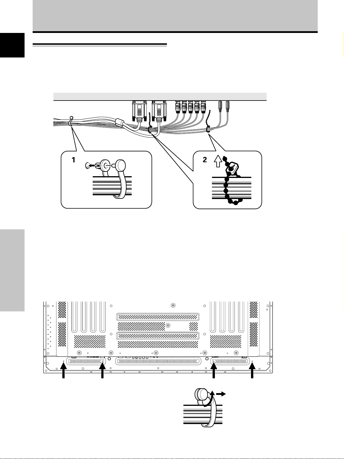
How to Route Cables
Speed clamps and bead bands are included with this unit
for bunching cables together. Once components are
connected, follow the following steps to route cables.
1
2
* As viewed from the rear of the display.
1 Organize cables together using the provided
speed clamps.
Insert 1 into an appropriate hole on the rear of the
unit, then snap 2 into the back of 1 to fix the clamp.
Speed clamps are designed to be difficult to undo
once in place. Please attach carefully.
To attach the speed clamps to the main unit
Connect the speed clamps using the 4 holes marked with •
(Black dot) below, depending on the situation.
Installation and Connections
To remove speed clamps
Using pliers, twist the clamp 90° and pull it outward.
In some cases the clamp may have deteriorated over
time and may get damaged when removed.
2 Bunch separated cables together and secure
them with the provided bead bands.
Note
Cables can be routed to the right or left.
Illustration depicts PDP-503MXE model.
16
En
Page 21
Setting Up the System
VGA WIDE VGA
XGA WIDE XGA
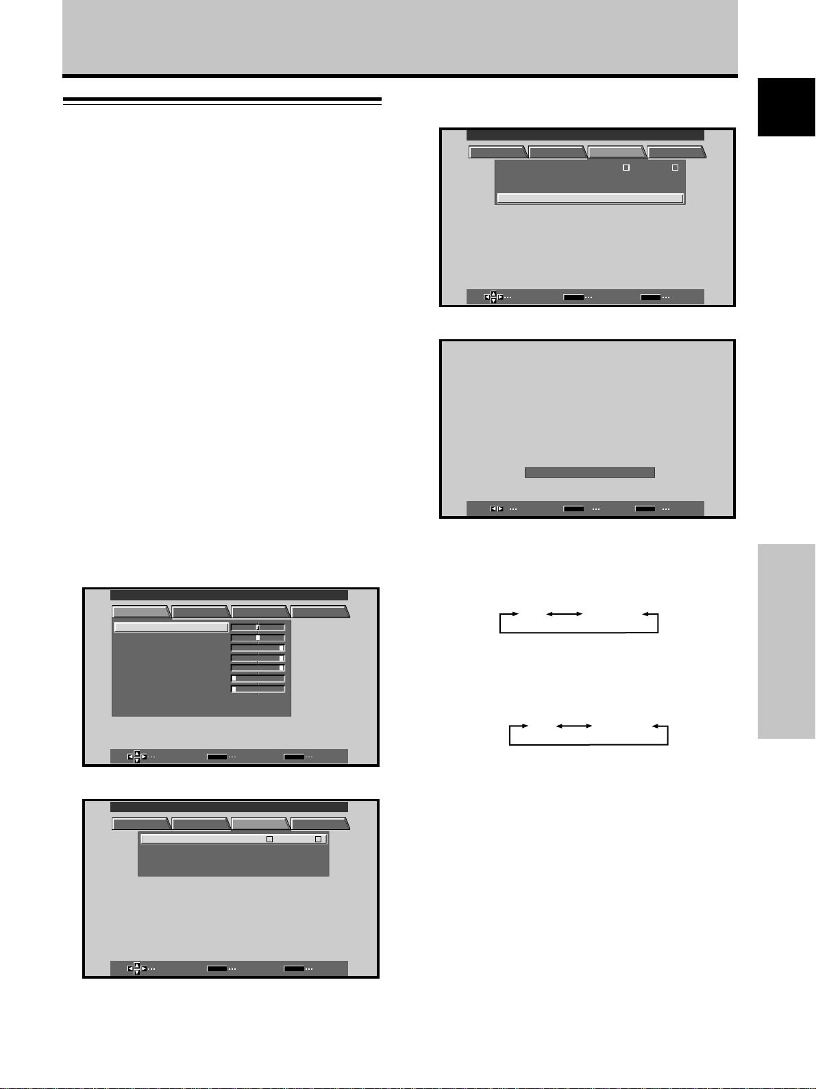
Setup after Connection
After components have been connected to INPUT1 or
INPUT2, on-screen setup is necessary.
Follow the procedure described below and make settings
as they apply to the type of components connected.
Screen Mode setup
Note
These settings are required only when using the following input
signal refresh rates: 1 31.5 kHz horizontal / 60 Hz vertical; 2
48.4 kHz horizontal / 60 Hz vertical, or 56.5 kHz horizontal / 70 Hz
vertical. No manual setup is necessary for signals with other
refresh rates, since adjustments are performed automatically (the
SETTING item will not be displayed).
1 Switch MAIN POWER on the connection panel to
the on position to turn on the unit’s main power.
The STANDBY/ON indicator lights red.
2 Press STANDBY/ON to put the unit in the
operation mode.
The STANDBY/ON indicator turns green.
3 Select INPUT1 or INPUT2.
4 Press MENU to display the menu screen.
The menu screen appears.
MAIN MENU INPUT1
PICTURE SCREEN SET UP OPTION
CONT RAS T
BR
IGHT.
RLEVEL
.
GLEVEL.
BLEVEL.
H E NHANCE.
V E NH ANCE.
RSETE
:
0
:
0
:
+
6
0
:
+
60
:
+
60
:
0
:
0
6 Press 5/∞ to select SETTING, then press SET.
MAIN MENU INPUT1
PICTURE SCREEN SET UP OPTION
MNAGEMEA
PSITIONO
G
LEBLA
SET
INPUT INPUT
POWER
CLAMP
SETT I N
SELECT ENTER EXIT
:
:
N
T
:
:
O
A
V
FF
UTO
GA
MENU
1
7 Press 2/3 to select the display mode.
:
SETT I NG
SELECT SET EXIT
1 When the input signal has a refresh rate of 31.5
kHz (horizontal) and 60 Hz (vertical), pressing 2/3
will cause the display mode to change alternately
as follows:
2 When the input signal has a refresh rate of 48.4
kHz horizontal / 60 Hz vertical, or 56.5 kHz
horizontal / 70 Hz vertical, pressing 2/3 will cause
the display mode to change alternately as follows:
V
GA
SET
MENU
English
Français
Setting Up the System
5 Press 2/3 to select SET UP.
MAIN MENU INPUT1
PICTURE SCREEN SET UP OPTION
INPUT INPUT
POWER
CLAMP
SETT I N
MNAGEMEA
PSITIONO
G
SET
LEBLA
SET
SELECT ENTER EXIT
SELECT ENTER EXIT
MENU
:
:
N
O
T
:
A
:
V
FF
UTO
GA
MENU
1
8 When the setup is completed, press MENU to exit
the menu screen.
Note
Make this setup for each input (INPUT1 and INPUT2).
17
En
Page 22
Setting Up the System
CLAMP POSITION setup
English
Depending on the signal, analog RGB signals may result
in the screen image appearing with a whitish or greenish
cast. In such cases, set “CLAMP POSITION” to LOCKED.
÷ Normally, leave this setting at AUTO.
Setup of CLAMP POSITION
1 Press MENU to display the menu screen.
The menu screen appears.
MAIN MENU INPUT1
PICTURE SCREEN SET UP OPTION
MNAGEMEA
PSITIONO
G
:
0
:
0
:
+
6
0
:
+
60
:
+
60
:
0
:
0
SET
LEBLA
MENU
:
:
N
O
T
:
A
:
V
FF
UTO
GA
1
CONT RAS T
BR
IGHT.
RLEVEL
.
GLEVEL.
BLEVEL.
H E NHANCE.
V E NH ANCE.
RSETE
SELECT ENTER EXIT
2 Press 2/3 to select SET UP.
MAIN MENU INPUT1
PICTURE SCREEN SET UP OPTION
INPUT INPUT
POWER
CLAMP
SETT I N
4 Press SET to select LOCKED.
MAIN MENU INPUT1
PICTURE SCREEN SET UP OPTION
MNAGEMEA
PSITIONO
G
LEBLA
SET
INPUT INPUT
POWER
CL AMP
SETT I N
SELECT CHANGE EXIT
:
:
N
O
T
:
L
:
V
FF
OCKED
GA
MENU
1
Mode selection will change as follows each time SET
is pressed.
3 AUTO
LOCKED 2
5 When the setup is completed, press MENU to exit
the menu screen.
Notes
÷ Make this CLAMP POSITION setting for each applicable input
(INPUT1 and INPUT2).
÷ When using this setup, be sure to carefully check the signal
output of the component that you are using. For details, please
refer to the instruction manual supplied with the component
you are connecting.
Setting Up the System
SELECT ENTER EXIT
SET
3 Press 5/∞ to select CLAMP POSITION.
MAIN MENU INPUT1
PICTURE SCREEN SET UP OPTION
MNAGEMEA
PSITIONO
G
LEBLA
N
SET
INPUT INPUT
POWER
CL AMP
SETT I N
SELECT CHANGE EXIT
18
En
MENU
:
:
O
T
:
A
:
V
FF
UTO
GA
1
MENU
Page 23
Operations
Selecting an Input Source
This section explains the basic operation of this unit.
Outlined on the following pages is how to turn the main
power on and off, put this unit in the operation or standby
mode and how to select connected components.
Before you begin, make sure you have:
• Made connections between this unit and personal
computer as described in the section “Installation and
Connections” starting on page 10.
• Set up the on-screen menu to input signals from
components connected to INPUT1 and INPUT2 as
described in the section “Setting Up the System” on
page 17.
If no connections are made to these terminals,
on-screen setup is not necessary.
2,5
2,5
3
3
3 Press INPUT on the remote control unit or the
main unit to select the input.
Input changes each time the main unit’s INPUT is
pressed as follows.
3 INPUT1
INPUT2 2
• When the menu screen is displayed, changing the
signal input will cause the menu screen to turn off.
• If the input computer signal is not supported by the
display, the following message will be displayed:
INPUT
1
CAU I O NT
POUSUPNSREDTINALG
:
:
CAU I O NT
TOU NOARFGE
:
:
k
1717
HzfV .
085
512 684
X
k
7715
HzfV .
020
––––
HzfH .
FULL
INPUT
1
HzfH .
English
Panel
Remote Control UnitMain Unit Operating
1 Switch MAIN POWER on the main unit to the on
position to turn the main power on.
The STANDBY/ON indicator lights red.
2 Press STANDBY/ON to put this unit in the
operation mode.
The STANDBY/ON indicator turns green.
FULL
Operations
4 Use VOLUME +/– on the remote control unit to
4
adjust the volume.
If no audio connections are made to this unit, this step
is not necessary.
5 When viewing is finished, press STANDBY/ON to
put the unit in standby mode.
The STANDBY/ON indicator will blink and then remain
lit (red) indicating that the standby mode is engaged.
Operation is not possible while the STANDBY/ON
indicator is blinking (red).
6 Switch MAIN POWER on the main unit to the off
position to turn the main power off.
The STANDBY/ON indicator may continue to light for a
short while even after the main power is turned off.
This is a result of residual electric load impressed on
the circuitry, and the light will turn off presently.
CAUTION
Please do not leave the same picture displayed on the screen for
a long time. Doing so may cause a phenomenon known as
“screen burn” which leaves a ghost, or residual, image of the
picture on the screen.
19
En
Page 24
Operations
To adjust the volume
English
VOLUME +/–
Press VOLUME on the remote control unit.
Use VOLUME + or VOLUME – to adjust the volume of
the connected speakers.
To confirm display settings
DISPLAY
:
VOLUME
5
To mute the sound
Operations
MUTING
ress MUTING on the remote control unit.
Press MUTING again to restore the sound.
Muting is automatically canceled about 8 minutes after
the button is pressed, and the volume level is adjusted to
the minimum level.
Press VOLUME + or VOLUME – to adjust the volume at
a desired level.
Press DISPLAY on the remote control unit.
The currently selected input, screen size and refresh rates
will be displayed for about 3 seconds.
INPUT
1
:
:
Note
The displayed refresh rates may be slightly different from actual
values.
k
531
HzfV .
060
X
460 840
HzfH .
ODBYTDOT
20
En
Page 25
Operations
Screen Size Selection
This unit incorporates screen modes of various height and
width ratios. For optimal viewing, we recommend that
you select the screen mode that best matches the video
source that you are viewing. Although these modes are
designed for full display of a picture on a wide screen, it is
our hope that you make use of them with a full
understanding of the manufacturer’s intentions.
Changing the screen size
The size of the image displayed on the screen, and the
range of the image shown can be set in one of four
modes on the PDP-503MXE, and in three modes on the
PDP-433MXE.
Press SCREEN SIZE to select the size.
The screen size changes each time SCREEN SIZE is
pressed as follows.
[PDP-503MXE]
3 DOT BY DOT 3 4:3
FULL 2PARTIAL 2
[PDP-433MXE]
3 DOT BY DOT 3 4:3
FULL 2
Consult the table Computer Signal Formats Supported
(pages 35 and 36) for information regarding screen sizes
supported by each signal format.
Notes
÷ When the PARTIAL or FULL setting is used to display a non-
wide screen 4:3 picture fully on a wide screen, a portion of the
picture may be cut off or appear deformed.
÷ Be aware that when the display is used for commercial or
public viewing purposes, selecting the PARTIAL or FULL mode
settings may violate the rights of authors protected under
copyright law.
÷ When DOT BY DOT or 4:3 screen sizes are selected, the
display position is moved slightly each time the power is
turned on, in order to prevent image burning.
During personal computer signal input
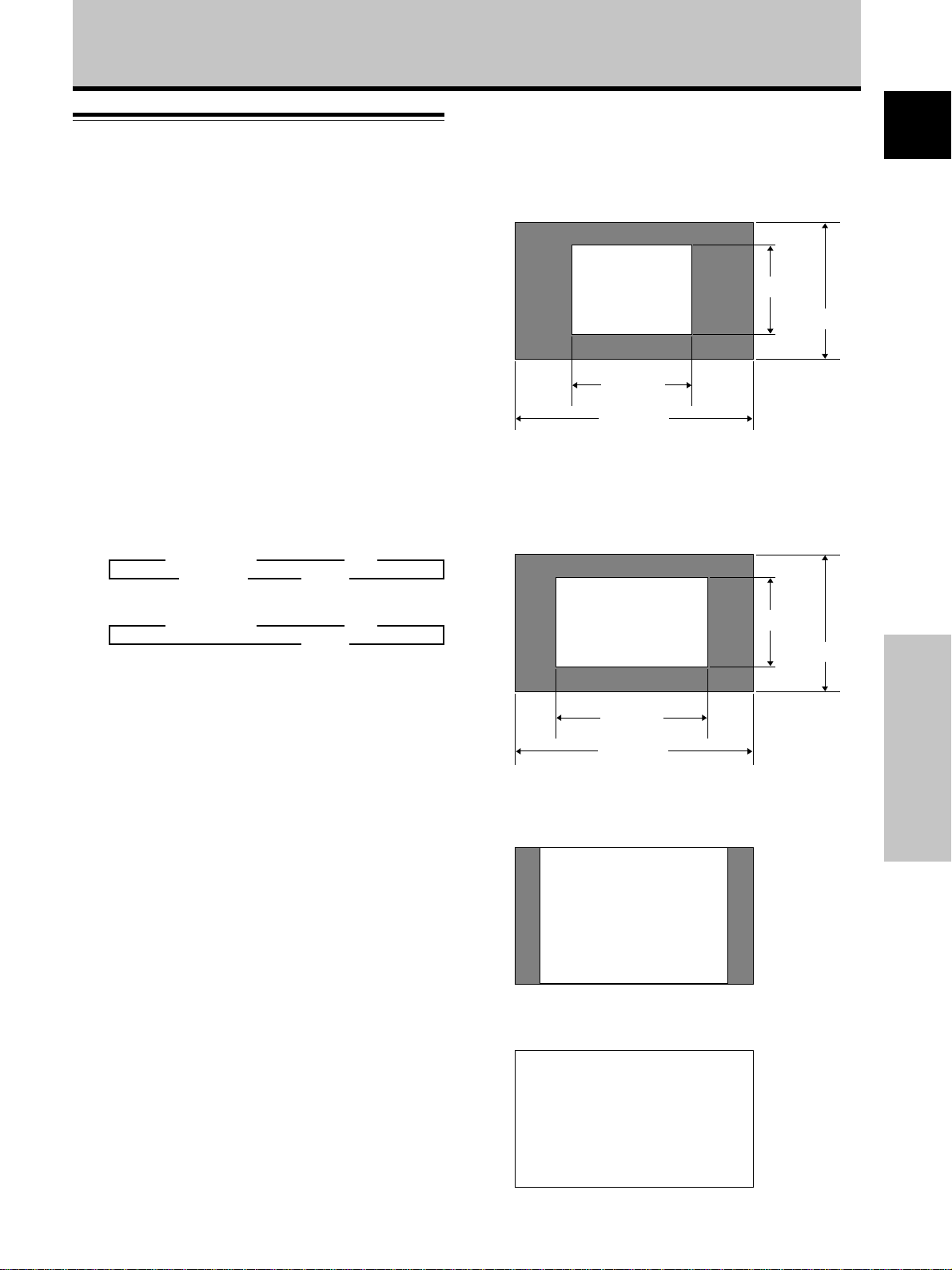
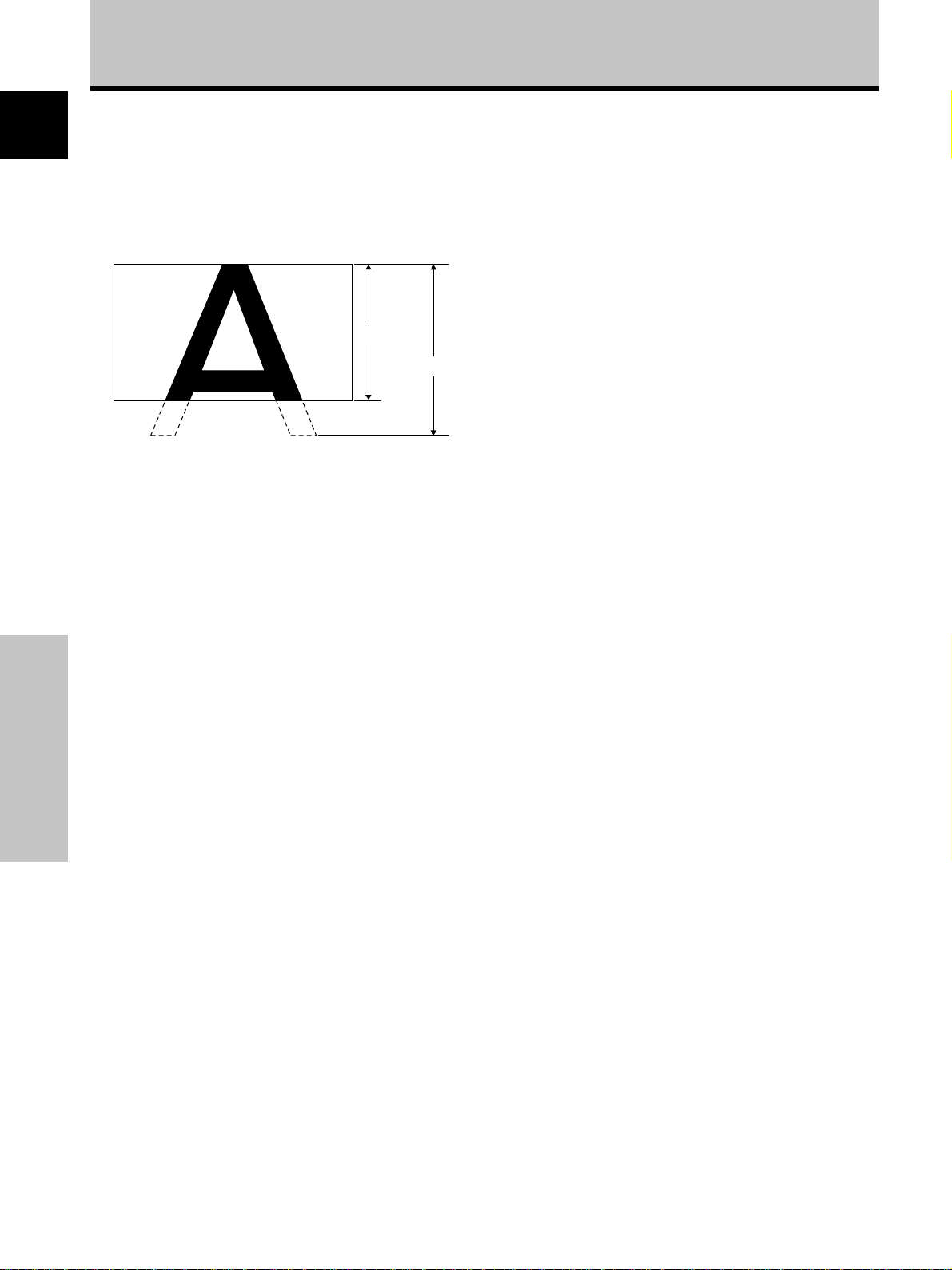
1 DOT BY DOT
The input signal and the screen maintain a dot to line ratio
of 1:1 and is thus highly faithful to the source.
[PDP-503MXE]
480 lines
A
640 dots
1280 dots
(Illustration shows 640 x 480 input.)
[PDP-433MXE]
* The PDP-433MXE is designed with horizontally
oblong elements, with the result that the image
displayed will appear more oblong than the original
input signal.
A
640 dots
1024 dots
(Illustration shows 640 x 480 input.)
2 4:3
The display fills the screen as much as possible without
altering the aspect ratio of the input signal.
768 lines
480 lines
768 lines
English
Operations
A
3 FULL
The display is presented with a widescreen aspect ratio
of 16:9 and fills the entire screen.
A
21
En
Page 26
Operations
4 PARTIAL (*Supported only on PDP-503MXE)
English
The PARTIAL setting is available only during personal
computer input (1280 x 1024/60 Hz only).
The input signal and the screen maintain a dot to line ratio
of 1:1. Display is highly faithful to the source. However, in
order to maintain the 1:1 ratio, a portion of the display will
not appear on the screen.
768 lines
Use 5/∞ to adjust the position of the video image on the
screen.
1024 lines
Moving the screen position
upward or downward
(*Supported only on PDP-503MXE)
During personal computer input (1280 x 1024/60Hz only),
even when the PARTIAL setting is selected, the position
of the screen can be adjusted by using 5/∞. The
adjustment value will not, however, be stored in memory.
Operations
22
En
Page 27
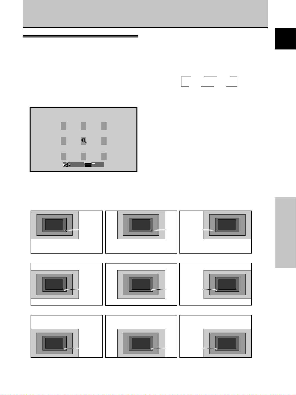
Partial Image Enlargement
Operations
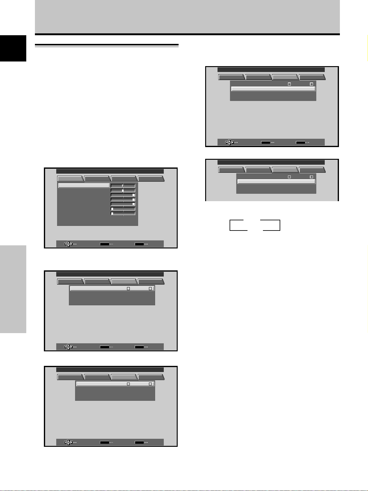
2 Press 5/∞/2/3 as required to select the desired
screen area (AREA 1 to AREA 9).
English
(POINT ZOOM)
This display allows any one of nine screen areas (AREA 1
to AREA 9) to be selected and enlarged to x1.5, x2, x3, or
x4. When performing point zoom enlargement, the
direction buttons (5/∞/2/3) can be used to move the
enlarged portion up-down and right-left.
1 Press the remote control unit’s POINT ZOOM.
P.ZOOM
SELECT
Note
Whenever point zoom is selected, the screen size automatically
changes to FULL.
EXIT
SET
ZOOM
3 Press SET to select the zoom ratio.
Pressing SET repeatedly changes the zoom ratio in
the following order:
3 x 1.5
x 4.0 2
3 x 2.0
x 3.0 2
÷ When the zoom ratio is changed, the screen image
is enlarged based on the screen center.
÷5/∞/2/3 can be used to move the enlarged portion
up-down and right-left.
÷ If no operation is undertaken for three seconds or
more, the display screen will disappear.
SET or 5/∞/2/3 can be pressed again if desired to
change the zoom ratio or display position.
4 Press the remote control unit’s POINT ZOOM once
again to cancel the point zoom operation.
The point zoom function will also be canceled
whenever the input signal changes, the menu screen
is displayed, or the INPUT changes.
AREA 1 display range
AREA 1
x 4.0
x 2.0
x 1.5
AREA 4 display range
AREA 4
x 4.0
x 2.0
x 1.5
AREA 7 display range
AREA 7
x 4.0
x 2.0
x 1.5
x 3.0
x 3.0
x 3.0
AREA 2 display range
AREA 2
x 4.0
x 2.0
x 1.5
AREA 5 display range
AREA 5
x 4.0
x 2.0
x 1.5
AREA 8 display range
AREA 8
x 4.0
x 2.0
x 1.5
AREA 3 display range
x 3.0
x 3.0
AREA 6 display range
x 3.0
x 3.0
AREA 9 display range
x 3.0
x 3.0
AREA 3
x 4.0
x 2.0
x 1.5
AREA 6
x 4.0
x 2.0
x 1.5
AREA 9
x 4.0
x 2.0
x 1.5
Operations
23
En
Page 28
Operations
English
Automatic Power OFF
This display is equipped with automatic powermanagement and auto-power-off functions, which allow
the unit to automatically switch to power-saving mode
when no sync signal is detected.
(A warning message appears onscreen before these
functions operate.)
Notes
÷ The Power Management function can be set only when the
INPUT 1 signal is selected.
÷ The automatic power-off function can be set only when the
INPUT 2 signal is selected.
÷ Always turn off the plasma display’s main power switch when
not using the display for extended periods of time.
1 Press MENU to display the menu screen.
MAIN MENU INPUT1
PICTURE SCREEN SET UP OPTION
CONT RAS T
BR
IGHT.
RLEVEL
.
GLEVEL.
BLEVEL.
H E NHANCE.
V E NH ANCE.
RSETE
SELECT ENTER EXIT
:
0
:
0
:
+
6
0
:
+
60
:
+
60
:
0
:
0
SET
MENU
2 Press 2/3 to select SET UP.
[When using INPUT 1]
MAIN MENU INPUT1
PICTURE SCREEN SET UP OPTION
:
:
N
O
T
FF
:
A
UTO
:
V
GA
MENU
:
LEBLA
:
O
O
FF
FF
:
A
UTO
:
V
GA
Operations
INPUT INPUT
POWER
CLAMP
SETT I N
SELECT ENTER EXIT
MNAGEMEA
PSITIONO
G
LEBLA
SET
[When using INPUT 2]
MAIN MENU INPUT2
PICTURE SCREEN SET UP OPTION
INPUT INPUT
AUTO POWER
CLAMP
SETT I N
PSITIONO
G
3 Press 5/∞ to select either the POWER
MANAGEMENT or AUTO POWER OFF mode.
[When using INPUT 1]
MAIN MENU INPUT1
PICTURE SCREEN SET UP OPTION
MNAGEMEA
PSITIONO
G
LEBLA
SET
INPUT INPUT
POWER
CLAMP
SETT I N
SELECT CHANGE EXIT
:
:
N
O
T
:
A
:
V
FF
UTO
GA
1
MENU
[When using INPUT 2]
MAIN MENU INPUT2
PICTURE SCREEN SET UP OPTION
INPUT INPUT
AUTO POWER
CLAMP
SETT I N
PSITIONO
G
:
LEBLA
:
O
O
FF
:
A
:
V
FF
UTO
GA
2
4 Press SET to confirm selection of the POWER
MANAGEMENT or AUTO POWER OFF.
÷ When OFF is selected, the display will continue in
operating mode, regardless of the presence/
absence of an input sync signal.
÷ When POWER MANAGEMENT: ON is selected, if
a sync signal is not detected, a warning message is
displayed for 8 seconds, after which the display
automatically enters the power-saving mode (*1)
1
and the STANDBY/ON indicator flashes green. If a
sync signal (*2) is input again later, the plasma
display automatically returns to normal operating
mode.
*1. Power consumption about 1W
*2. Except when input signal is SYNC on G or composite
SYNC
÷ When AUTO POWER OFF: ON is selected and if no
sync signal is detected for 8 minutes or more, a
warning message will be displayed for 30 seconds
after which the unit's power will switch to
STANDBY mode.
2
5 When the setup is finished, press MENU to exit
the menu screen.
Note
The POWER MANAGEMENT and AUTO POWER OFF functions
must be set individually for each input (INPUT 1 or INPUT 2).
3 OFF
ON 2
24
En
SELECT ENTER EXIT
SET
MENU
To return to operating mode:
÷ To return to normal operation from POWER
MANAGEMENT mode: either operate the computer,
or press INPUT on the Main Unit Operating Panel or
remote control unit.
÷ To return to normal operation from AUTO POWER
OFF mode: Press STANDBY/ON on the Main Unit
Operating Panel or remote control unit.
Page 29
Display Panel Adjustments
Adjusting the Picture Quality
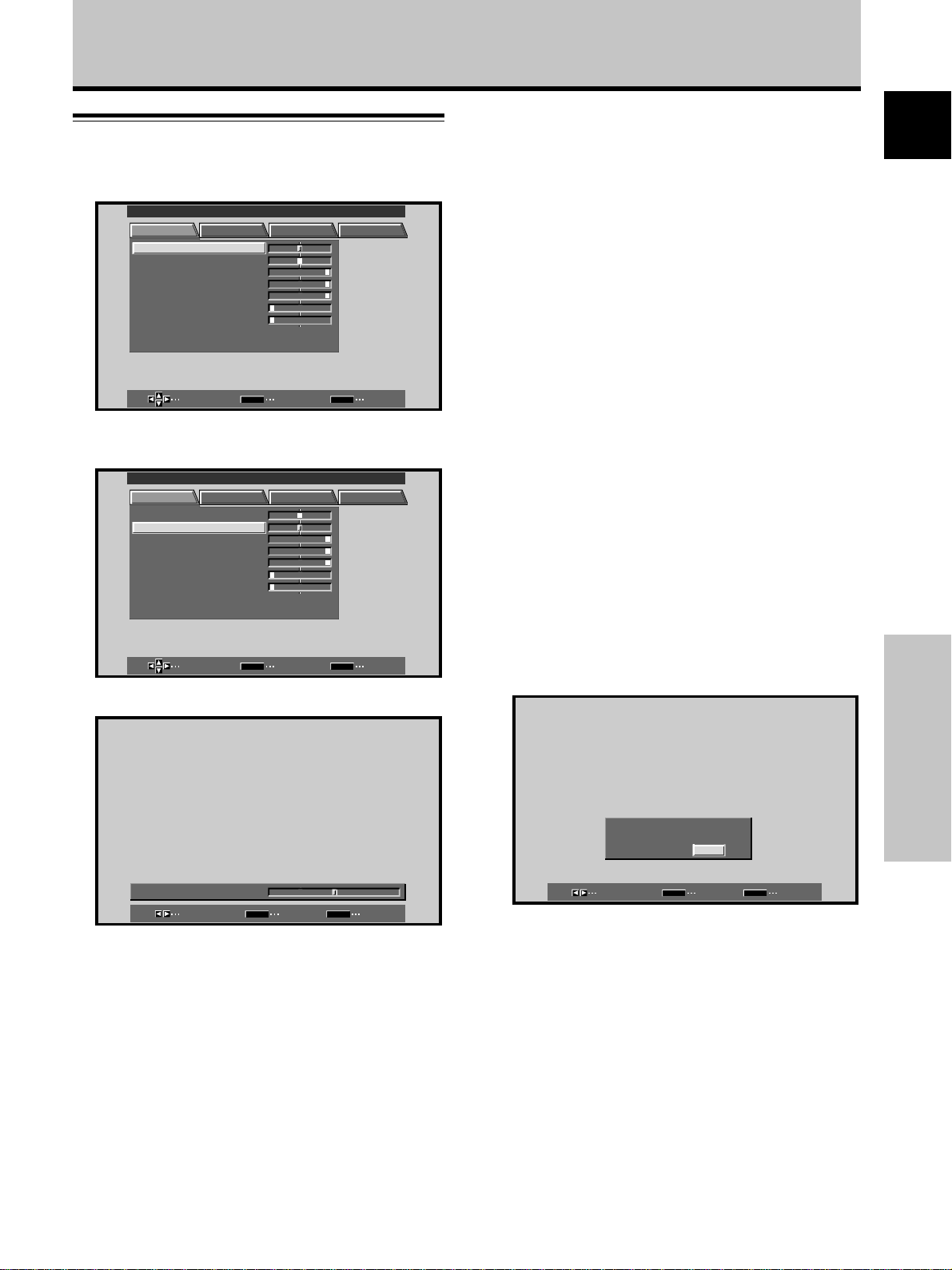
1 Press MENU to display the menu screen.
MAIN MENU INPUT1
PICTURE SCREEN SET UP OPTION
CONT RAS T
BR
IGHT.
RLEVEL
.
GLEVEL.
BLEVEL.
H E NHANCE.
V E NH ANCE.
RSETE
SELECT ENTER EXIT
2 Press 5/∞ to select the adjustment item, then
press SET.
MAIN MENU INPUT1
PICTURE SCREEN SET UP OPTION
CONT RAST
BR
IGHT.
RLEVEL
.
GLEVEL.
BLEVEL.
H E NHANCE.
V E NH ANCE.
RSETE
:
0
:
0
:
+
6
0
:
+
60
:
+
60
:
0
:
0
SET
:
0
:
0
:
+
6
0
:
+
60
:
+
60
:
0
:
0
MENU
PICTURE mode adjustment items
Below are brief descriptions of the options that can be set
in the PICTURE mode.
CONTRAST ············· Adjust according to the surrounding
brightness so that the picture can be
seen clearly.
BRIGHT. ·················· Adjust so that the dark parts of the
picture can be seen clearly.
R. LEVEL ················· Adjust the amount of red in the
picture.
G. LEVEL ················· Adjust the amount of green in the
picture.
B. LEVEL ················· Adjust the amount of blue in the
picture.
H. ENHANCE··········· Sharpens the image in the horizontal
direction.
V. ENHANCE ··········· Sharpens the image in the vertical
direction.
To reset PICTURE mode settings to the default
If settings have been adjusted excessively or the picture
on the screen no longer appears natural, it may prove
more beneficial to reset the PICTURE mode to default
settings instead of trying to make adjustments under
already adjusted conditions.
English
SELECT ENTER EXIT
SET
MENU
3 Press 2/3 to adjust the picture quality as desired.
:
BR I GH T.
ADJUST SET EXIT
0
SET
MENU
4 Press SET.
Pressing SET writes the value into the memory and
returns the display to the step 2 screen.
5 When the setup is finished, press MENU to exit
the menu screen.
Note
Make these adjustments for each input (INPUT1 to INPUT2) and
signals.
1 In step 2 in the previous procedure, press 5/∞ to
select RESET, then press SET.
PICTURE RESE
S
YE
SELECT SET EXIT
SET
T?
NO
MENU
2 Press 2/3 to select YES, and press SET.
All PICTURE mode settings are returned to the factory
set default.
Display Panel Adjustments
25
En
Page 30
Display Panel Adjustments
English
Adjusting the Image Position and
Clock (Automatic Adjustment)
Pressing AUTO SET UP on either the display or the
remote control unit will adjust the screen position and
clock to optimum values.
Note
Perform this adjustment individually for each input function
(INPUT 1, INPUT 2), and each signal type.
AUTO
SET UP
AUTO SET UP
Main Unit Operating Panel Remote Control Unit
Press AUTO SET UP on either the main unit or remote
control unit.
Display Panel Adjustments
÷ Optimum settings may not be possible for low-
luminance and certain other kinds of signals. In this
case, follow the instructions in the section “Manual
Adjustment of Screen Position and Clock” to make
more precise adjustments.
26
En
Page 31

Display Panel Adjustments
Manual Adjustment of Screen
Position and Clock
1 Press MENU to display the menu screen.
MAIN MENU INPUT1
PICTURE SCREEN SET UP OPTION
CONT RAS T
BR
IGHT.
RLEVEL
.
GLEVEL.
BLEVEL.
H E NHANCE.
V E NH ANCE.
RSETE
SELECT ENTER EXIT
2 Press 2/3 to select SCREEN.
MAIN MENU INPUT1
PICTURE SCREEN SET UP OPTION
POS I T I ON
CL OC HASEK/ /
RSETE
SELECT ENTER EXIT
3 Press 5/∞ to select the adjustment item, then
press SET.
MAIN MENU INPUT1
PICTURE SCREEN SET UP OPTION
POS I T I ON
CL OC HASEK/ /
RSETE
SELECT ENTER EXIT
:
0
:
0
:
+
6
0
:
+
60
:
+
60
:
0
:
0
SET
:
00
:
P
P
SET
:
:
SET
00
00
00
MENU
/
MENU
/
MENU
5 Press SET.
Pressing SET writes the value into the memory and
returns the display to the step 3 screen.
6 When adjustment is finished, press MENU to exit
the menu screen.
Note
Make these adjustments for each input (INPUT1 to INPUT2) and
signals.
SCREEN mode adjustment items
Below are brief descriptions of the options that can be set
in the SCREEN mode.
POSITION
H.POSITION ·········· Adjust the picture’s position to the
left or right.
V.POSITION ·········· Adjust the picture’s position upward
or downward.
CLOCK/PHASE
CLOCK ·················· Adjust letter breakup or noise on the
screen. This setting adjusts the
unit’s internal clock signal
frequency that corresponds to the
input video signal.
PHASE ·················· Adjust so that there is minimum
flicker of screen letters or color
misalignment. This setting adjusts
the phase of the internal clock
signal adjusted by the CLOCK
setting.
Notes
÷ When CLOCK adjustment is carried out, the H.POSITION
setting may have to be re-adjusted.
÷ If the adjustment items in the SCREEN mode are adjusted
excessively, the picture may not be displayed properly.
To reset SCREEN mode settings to the default
If settings have been adjusted excessively or the picture
on the screen no longer appears natural, it may prove
more beneficial to reset the SCREEN mode to default
settings instead of trying to make adjustments under
already adjusted conditions.
1 In step 3 in the previous procedure, press 5/∞ to
select RESET, then press SET.
English
Display Panel Adjustments
4 Press 2/3 to carry out the adjustment.
MENU
SET
:
0
:
0
EXIT
SET
POH. S I T I ON
POV. S I T I ON
ADJUST
Use 5/∞ for the adjustments of V.POSITION and
PHASE.
SCREEN RESE
YES
SELECT SET EXIT
SET
T?
NO
MENU
2 Press 2/3 to select YES, and press SET.
All SCREEN mode settings are returned to the factory
set default.
27
En
Page 32
Other Operations
English
Rewriting the Input Display
(INPUT LABEL)
This function allows rewriting of the screen contents
displayed with differing inputs. For example, the default
“INPUT 1” can be changed to “COMPUTER” or other
name describing the connected component (up to
maximum of 8 characters).
Example: To rewrite the default “INPUT 1” message
to display “COMPUTER” instead.
5 Press 2/3/5/∞ to select the first desired
character (here, “C”), then press SET to confirm
(repeat this step to input up to eight desired
characters.)
MAIN MENU INPUT1
INPUT
1
I NP UT
A
C I
0123456 87
'"
()
–
/
TESRE
@
LEBLA
BACK SPACE
J
W
9
.,
:
#
?
ECASP DNE
&
MKLBCDEFGH
ZXYNOPQRST VU
~
1 Press INPUT and set input to INPUT 1.
2 Press MENU to display the menu screen.
MAIN MENU INPUT1
PICTURE SCREEN SET UP OPTION
CONT RAS T
BR
IGHT.
RLEVEL
.
GLEVEL.
BLEVEL.
H E NHANCE.
V E NH ANCE.
RSETE
SELECT ENTER EXIT
:
0
:
0
:
+
6
0
:
+
60
:
+
60
:
0
:
0
SET
3 Press 2/3 to select SET UP.
MAIN MENU INPUT1
PICTURE SCREEN SET UP OPTION
INPUT INPUT
POWER
CLAMP
SETT I N
MNAGEMEA
PSITIONO
G
LEBLA
N
Other Operations
SELECT ENTER EXIT
SET
4 Press SET to select INPUT LABEL.
MAIN MENU INPUT1
SELECT SET EXIT
SET
MENU
÷ Usable characters include 52 types displayable on
screen.
÷ When a character is selected and SET pressed, the
input point (cursor position) advances by one.
÷ If you input a mistaken character, press BACK SPACE
followed by SET to move the input point (cursor
position) back by one.
÷ To return the display to its default value, press
RESET followed by SET.
MAIN MENU INPUT1
MENU
OMPUT ER
A
0123456 87
:
:
O
T
:
A
:
V
FF
UTO
GA
1
'"
INPUT
C
R
()
–
/
TESRE
SELECT SET EXIT
@
SET
LEBLA
BACK SPACE
J
W
9
.,
:
#
?
ECASP DNE
MENU
MKLBCDEFG IH
ZXYNOPQ ST VU
~
&
6 After setting all inputs as desired, press 2/3/5/∞
to select END , followed by SET.
MENU
MAIN MENU COMPUTER
PICTURE SCREEN SET UP OPTION
INPUT MPCO UTE RLEBLA
POWER
MNAGEMEA
CLAMP
SETT I N
PSITIONO
G
:
:
N
O
T
FF
:
A
UTO
:
V
GA
28
En
INPUT
1
INPUT
A
0123456 87
'"
()
–
/
TESRE
SELECT SET EXIT
@
SET
:
ECASP
LEBLA
BACK SPACE
J
W
9
#
.,
?
&
MENU
MKLBCDEFG IH
ZXYNOPQRST VU
~
DNE
7 Press MENU to return to the normal display
SELECT ENTER EXIT
SET
MENU
screen.
Page 33

Other Operations
Power Control Function
The power control function allows screen brightness to
be suppressed as a means of lowering power
consumption and reducing display deterioration.
1 Press MENU to display the menu screen.
The menu will be displayed.
MAIN MENU INPUT1
PICTURE SCREEN SET UP OPTION
CONT RAS T
BR
IGHT.
RLEVEL
.
GLEVEL.
BLEVEL.
H E NHANCE.
V E NH ANCE.
RSETE
SELECT ENTER EXIT
2 Press 2/3 to select OPTION.
MAIN MENU INPUT1
PICTURE SCREEN SET UP OPTION
:
0
:
0
:
+
6
0
:
+
60
:
+
60
:
0
:
0
SET
POWE R NDSTA ARDRTLONCO
AUT O CTTIONNF
AUD I O O
U
MENU
:
:
OF F
UFIEXD
:
AUTO FUNCTION
This display is equipped with an optional AUTO
FUNCTION selector. When enabled, the selector
automatically switches the display’s input source to
INPUT 1 when an image signal is detected at the INPUT 1
terminal.
1 Press MENU.
The onscreen menu will be displayed.
MAIN MENU INPUT1
PICTURE SCREEN SET UP OPTION
CONT RAS T
BR
IGHT.
RLEVEL
.
GLEVEL.
BLEVEL.
H E NHANCE.
V E NH ANCE.
RSETE
SELECT ENTER EXIT
2 Press 2/3 to select OPTION.
MAIN MENU INPUT1
PICTURE SCREEN SET UP OPTION
:
0
:
0
:
+
6
0
:
+
60
:
+
60
:
0
:
0
SET
POWE R NDSTA ARDRTLONCO
AUT O CTTIONNF
AUD I O O
U
MENU
:
:
OF F
UFIEXD
:
English
SELECT CHANGE EXIT
SET
MENU
3 Press SET to select POWER CONTROL.
The unit has been factory set to the STANDARD
setting. Each time SET is pressed, the setting
changes as follows:
3 STANDARD
MODE 2 2 MODE 1 2
÷ When STANDARD is set, screen brightness is
reduced in accordance with the input signal, thus
producing bright, easy-to-view images.
÷ Selecting MODE 1 reduces brightness in the same
way as the STANDARD setting, but at a even lower
levels of power consumption.
÷ MODE 2 fixes the screen brightness regardless of
the input signal. This is effective for reducing panel
deterioration due to screen burning.
4 Following completion of settings, press MENU to
return to normal screen display.
Note
The POWER CONTROL setting affects all input sources.
SELECT CHANGE EXIT
SET
MENU
3 Press 5/∞ to select AUTO FUNCTION.
MAIN MENU INPUT1
PICTURE SCREEN SET UP OPTION
POWE R NDSTA ARDRTLONCO
AUTO CTTIONNF
AUD I O O
SELECT CHANGE EXIT
U
UFIEXD
SET
:
:
:
OF F
MENU
Other Operations
29
En
Page 34

Other Operations
4 Press SET to select INPUT 1.
English
The factory default setting is OFF. Each time SET is
pressed the selector function switches alternately as
shown:
3 OFF
INPUT1 2
÷ When OFF is selected, AUTO FUNCTION is
disabled.
÷ When INPUT 1 is selected, the display input
automatically switches to INPUT 1 when a signal is
detected at the INPUT 1 jack. Thereafter, the input
will not change even if the INPUT button is pressed
on the remote control unit or display.
Once the function has switched to INPUT 1 by
operation of the AUTO FUNCTION facility, if the
input signal is no longer detected at the INPUT 1
terminal, the function will automatically switch back
to the original input source used before the AUTO
FUNCTION facility was enabled.
5 Following completion of settings, press MENU
again to return the display to its normal screen.
Note
The AUTO FUNCTION for INPUT1 is supported only when a
separate SYNC or composite SYNC analog RGB signal is input.
(When a G on SYNC or component video signal is input, AUTO
FUNCTION is disabled.)
Audio Output (AUDIO OUT)
2 Press 2/3 to select OPTION.
MAIN MENU INPUT1
PICTURE SCREEN SET UP OPTION
POWE R NDSTA ARDRTLONCO
U
AUT O CTTIONNF
AUD I O O
SELECT CHANGE EXIT
UFIEXD
SET
:
:
:
OF F
MENU
3 Press 5/∞ to select AUDIO OUT.
MAIN MENU INPUT1
PICTURE SCREEN SET UP OPTION
POWE R NDSTA ARDRTLONCO
U
AUT O CTTIONNF
AUD I O O
SELECT CHANGE EXIT
UFIEXD
SET
:
:
:
OF F
MENU
4 Press SET to select the desired audio level setting.
The factory default setting is FIXED. Each time SET is
pressed, the function alternates as shown:
3 FIXED
VARIABLE 2
The signal level produced at the AUDIO OUT jack can be
set to FIXED or VARIABLE (linked to the VOLUME) as
desired.
Other Operations
1 Press MENU.
The onscreen menu will be displayed.
MAIN MENU INPUT1
PICTURE SCREEN SET UP OPTION
CONT RAS T
BR
IGHT.
RLEVEL
.
GLEVEL.
BLEVEL.
H E NHANCE.
V E NH ANCE.
RSETE
SELECT ENTER EXIT
:
0
:
0
:
+
6
0
:
+
60
:
+
60
:
0
:
0
SET
MENU
÷ When FIXED is selected, the audio output volume
will not change, even if the setting of the display’s
VOLUME function is later changed.
÷ When VARIABLE is selected, the level of the output
signal changes in accordance with the setting of the
VOLUME function.
5 Following completion of settings, press MENU to
return to normal screen display.
Note
The AUDIO OUT setting affects all input sources.
30
En
Page 35

Additional Information
Cleaning
Regular cleaning will extend the life and performance of
this unit. The recommended way to clean the display and
related parts is described below.
Before cleaning, be sure to unplug the power cord from
the power outlet.
Cleaning the display panel body and remote
control
Do not under any circumstances use solvents such as
benzine or thinner for cleaner. Use of such liquids may
cause deterioration or peeling of paint from the display or
remote control unit.
Wipe the display and remote control gently with a soft
cloth. In the case of excessive dirt buildup, dampen a soft
cloth with a diluted neutral cleaning detergent and after
wringing the cloth thoroughly, wipe the component and
then dry it with a dry soft cloth.
Cleaning the screen
After dusting, wipe the screen gently using the supplied
cleaning cloth or a soft cloth. Do not use tissue or a rough
cloth. As the surface of the screen is easily scratched, do
not rub it or hit it with a hard object.
Troubleshooting
What may at first seem to be an malfunction, may be
remedied with a quick check.
Please check to see if a warning is displayed on the
screen. If displayed, refer to the table below and check
the mode. If there is no display check to see if the
problem is listed on page 32. The problem may also be
caused by something other than this unit so please also
check the other components being used such as a video
deck. If the problem can still not be solved please consult
the dealer where this unit was purchased.
About the self diagnosis mode
Messages appear on the bottom of this unit’s screen to
indicate operation or connection faults. After message
confirmation, check the condition of the unit.
ERROR MESSAGE
CAUTION
OUT OF RANGE or
CAUTION
UNSUPPORTED SIGNAL
¶ The current input signal is
REMEDY
not supported by the unit.
Consult the table of
supported computer input
signals on pages 35 – 36
and set the computer's
output signal appropriately.
English
Cleaning the vents
As a general rule, use a vacuum cleaner about once a
month to clean the vents on the rear panel of the display
of dust buildup (set the vacuum cleaner to its weakest
setting when doing this).
Using the unit without cleaning it of dust will cause the
internal temperature to increase, resulting in possible
breakdown or fire.
Vents
Vents
Vents
Illustration depicts PDP-503MXE model.
WARNING THERMAL ALERT
WARNING FAN FAILURE
VentsVents
ERROR INVALID KEY ENTRY
SHUT DOWN
¶ Turn off main power (page
9).
¶ Is ambient temperature
above 40˚C?
¶ Remove any objects
blocking the cooling vents
on the plasma display.
¶ Cooling fan has
malfunctioned.
Immediately turn off
power, remove power plug
from its outlet, and consult
a Pioneer service center or
your dealer.
¶ An invalid operation has
been attempted. Check
input signals, connections
and other settings.
¶ Turn off main power, wait
for 1-2 minutes, then try
turning power on again. If
problem persists, remove
power plug from its outlet
and consult a Pioneer
service center or your
dealer.
Additional Information
31
En
Page 36

Additional Information
General problems
English
• No power
• Unit cannot be operated.
• Remote control does not
operate.
• INPUT is not changed.
• Picture is cut off.
• Strange color, light color, or
dark, or color misalignment
• Power is suddenly turned
off.
• No picture
Problem Possible Solution
• Is the power cord disconnected? (page 15)
• Has the MAIN POWER switch been switched on? (page 9)
• External influences such as lightning, static electricity, etc., may cause improper operation. In this
case, operate the unit after first turning the MAIN POWER on/off, or unplugging the power cord
and re-plugging it in after 1 to 2 minutes.
• Are batteries inserted with polarity (+, –) correctly aligned? (page 7)
• Are batteries worn out? (Replace with new batteries).
• Is a plug connected to the CONTROL IN connector?
When a plug is connected to the CONTROL IN connector, the signal from that connector is given
priority, thus disabling the remote control signal receiver (page 15).
• Is the Auto function being used? (page 29)
• Is the selected screen size correct?
Switch to another screen size (page 21).
• Are SCREEN mode adjustments such as picture size made correctly? (pages 26–27).
• Is the Point Zoom function being used? (page 23)
• Adjust the picture tone (page 25).
• Is the room too bright?
The picture may look dark in a room that is too bright.
• Is CLAMP POSITION setup correct? (page 18)
• The unit’s internal temperature has increased. (Air vents are blocked.)
Remove any objects blocking vent or clean (page 31).
• Is the POWER MANAGEMENT or AUTO POWER OFF function set to ON? (page 24).
• Condensation has formed on internal parts due to suddenly increasing ambient temperature.
Allow condensation to dry thoroughly before using.
• Is connection to other components correct? (pages 12 to 14)
• Has setup been done correctly after connection? (pages 17 and 18)
• Is the correct input selected? (page 19)
• Is a non-compatible signal being input? (pages 12, 35 and 36)
• Is picture adjustment correct? (page 25)
Problems commonly mistaken as breakdown
Problem Possible Solution
• The screen is displayed in a
small size.
Additional Information
• Letter breakup on screen.
• A sharp sound is sometimes
heard from the cabinet.
• Bright portions of image
appear to be losing intensity.
• Speckles or noise appears on
screen.
• Stripes appear on the screen.
• Operation is not possible.
• Sound is heard from inside
the unit.
• Fan isn’t moving.
• Fan speed changes.
• Check the input signal compatibility chart (pages 35 and 36).
• Is the correct screen size selected? (pages 21, 26 and 27)
• Adjust using “SCREEN” mode on the menu screen (page 27).
If there is still no improvement, this unit may be limiting the displayable range. Check the
personal computer input signal compatibility chart (pages 35 and 36).
• Expansion/contraction caused by surrounding temperature change may result in sound being
heard from the cabinet. This is not a malfunction.
• When the video input signal’s level is too high, the bright portions may appear to be losing their
intensity.
Increase the adjustment level of the contrast and check the picture (page 25).
• May be caused by radio wave interference from appliances with motors such as hair dryers,
electric vacuum cleaners, electric power drills, ignition systems of cars, motorcycles etc., switch
devises such as thermostats etc., neon signs or electrical discharge from power lines etc.
• May be caused by radio wave mingling from TV station, FM station, amateur radios, public radios
(simplified radios) etc., or a nearby personal computer, TV, or video/audio component.
• A strong electromagnetic field may cause picture distortion and similar problems.
• External influences such as lightning strike, static electricity etc., may cause improper operation.
In this case, operate the unit after first turning the MAIN POWER ON/OFF, or unplugging the
power cord and re-plugging it in after 1 to 2 minutes.
• Normal sound of the cooling fan and internal sliding parts of the plasma display panel. Not a
malfunction.
• Fan is set to operate only after ambient temperature exceeds 35°C (differs depending on
installation conditions). Not a malfunction.
• Fan speed changes automatically in accordance with ambient conditions. Not a malfunction.
32
En
Page 37

Additional Information
Although this unit incorporates high precision technology
in its design, please understand that there may be
extremely slight pixel breakup, or light emission fault.
Note
In order to protect the panel and internal circuitry, this display is
provided with a cooling fan designed to turn on/off and change
speed automatically in accordance with ambient temperature
conditions (the fan sound will change in accordance with its
speed). The display should be used within ambient temperature
conditions below 40°C.
Additional cautions
• If the power is automatically turned off during operation
of this unit, the following reasons may be the cause.
1 Is the POWER MANAGEMENT or AUTO POWER
OFF function set to ON? (page 24).
2 The surrounding temperature has risen above 40 °C.
The display should be used within ambient
temperature conditions below 40°C.
3 The internal temperature has risen abnormally due to
blocked cooling vents, overheating of internal
electronic parts, or other factors.
4 If the display is moved suddenly from a chilled
location to a warm room, or if the room temperature
rises suddenly, condensation may form on internal
parts. To protect internal circuitry, the display is
provided with a condensation detector that
automatically disables power in event of internal
condensation; in this case, allow the unit to dry
thoroughly before using.
If the power is automatically turned off for a reason
other than the above reasons, there could be a
malfunction. In this case, unplug the power cord from
the power outlet and request repair from your nearest
sales outlet.
• The plasma display panel of this unit is very bright and
viewing it a close distance will cause eye strain.
We recommend that you view the screen from a
suitable distance (3 to 6m).
STANDBY/ON indicator
During operation of the Power Management function, the
indicator will flash green at intervals of about 2 seconds
(page 24). If the green light displays a flashing pattern
other than the above, an error message is indicated.
Consult any onscreen messages (page 31) and check
ambient conditions (temperature, condensation, etc.) and
respond accordingly (pages 32 – 33).
If the problem persists, disconnect the power plug and
consult your dealer or a service center.
When STANDBY/ON is pressed to set the unit to the
standby mode, the indicator will flash red for several
seconds (page 19). Other than this, if the power turns off
by itself, or refuses to turn on, or if the red indicator
conditions flashing, a malfunction may be indicated.
Immediately disconnect the power plug and consult your
dealer or a service center.
About the plasma panel’s
protection function
The brightness of this display will deteriorate slightly
when an image with little movement such as a
photograph or computer image is continuously displayed.
This is caused by the plasma panel’s protection function
which detects images with slight movement and
automatically adjusts brightness to protect the display,
and is not a malfunction.
The screen-saver function begins operating when the
display detects no or little screen movement for a period
of about three minutes.
CAUTION
Panel sticking and after-image lag
• Displaying the same images such as still images for a
long time may cause after-image lagging.
This may occur in the following two cases.
1.After-image lagging due to remaining electrical load
When image patterns with very high peak luminance are
displayed for more than 1 minute, after-image lagging may
occur due to the remaining electric load. The after-images
remaining on the screen will disappear when moving images
are displayed. The time for the after-images to disappear
depends on the luminance of the still images and the time
they had been displayed.
2. After-image (lag image) due to burning
Avoid displaying the same image on the Plasma Display
continuously over a long period of time. If the same image is
displayed continuously for several hours, or for shorter
periods of time over several days, a permanent after-image
may remain on the screen due to burning of the fluorescent
materials. Such images may become less noticeable if
moving images are later displayed, but they will not
disappear completely.
• The power control function can be set to help prevent
damage from screen burning (page 29).
Note
Special precautions must be employed when using
the plasma display as a surveillance monitor or in
other applications where a fixed image will be
displayed for extended periods of time. Before using
the monitor in such applications, consult your dealer
for advice.
33
English
Additional Information
En
Page 38

Additional Information
English
Specifications
General (PDP-503MXE)
Light emission panel ............ 50 inch plasma display panel
Number of pixels .............................................. 1280 x 768
Power supply ............................. AC 100 - 240 V, 50/60 Hz
Rated current ................................................. 3.8 A - 1.6 A
Standby power consumption ...................................... 1 W
External dimensions ........ 1218 (W) x 714 (H) x 98 (D) mm
(including display stand)
...................................... 1218 (W) x 737 (H) x 300 (D) mm
Weight.................................................................... 38.9 kg
(including display stand) ......................................... 39.5 kg
Operating temperature range............................. 0 to 40 °C
Operating atmospheric pressure range
................................................................. 800 to 1100 hPa
General (PDP-433MXE)
Light emission panel ............ 43 inch plasma display panel
Number of pixels .............................................. 1024 x 768
Power supply ............................. AC 100 - 240 V, 50/60 Hz
Rated current ............................................. 2.98 A - 1.24 A
Standby power consumption ...................................... 1 W
External dimensions ........ 1070 (W) x 630 (H) x 98 (D) mm
(including display stand)
...................................... 1070 (W) x 653 (H) x 300 (D) mm
Weight.................................................................... 31.5 kg
(including display stand) ......................................... 32.1 kg
Operating temperature range............................. 0 to 40 °C
Operating atmospheric pressure range
................................................................. 800 to 1100 hPa
Additional Information
Input/output
Video
INPUT 1
Input Mini D-sub 15 pin (socket connector)
RGB signal (SYNC ON G compatible)
RGB ... 0.7 Vp-p/75 Ω/no sync.
HD/CS, VD ... TTL level
/positive and negative polarity
/2.2 kΩ
SYNC ON G
... 1 Vp-p/75 Ω/negative sync.
*Compatible with Microsoft’s Plug & Play
(VESA DDC1/2B)
INPUT 2
Input BNC jack (x5)
RGB signal (SYNC ON G compatible)
RGB ... 0.7 Vp-p/75 Ω/no sync.
HD/CS, VD ... TTL level
/positive and negative polarity/
75 Ω or 2.2 kΩ
(impedance switch)
SYNC ON G ...
1 Vp-p/75 Ω/negative sync.
Audio
Input AUDIO INPUT (for INPUT 1/2)
Stereo mini jack
L/R ... 500mVrms/more than 10 kΩ
Output AUDIO OUTPUT
Stereo mini jack
L/R ... 500mVrms (max)/less than 5 kΩ
SPEAKER
L/R ... 8 – 16 Ω/2W +2W (at 8 Ω)
Control
RS-232C ... D-sub 9 pin (pin connector)
COMBINATION IN/OUT
... Mini DIN 6 pin (x2)
CONTROL IN/OUT ... monaural mini jack (x2)
Accessories
Remote control unit ......................................................... 1
Remote control unit holder .............................................. 1
AA (R6) batteries .............................................................. 2
Cleaning cloth ................................................................... 1
Speed clamps ................................................................... 2
Bead bands ...................................................................... 2
Operating Instructions...................................................... 1
Display stands .................................................................. 2
Washers ........................................................................... 2
Hex hole bolts (M8X40).................................................... 2
Ferrite core ....................................................................... 1
Cable tie ........................................................................... 1
÷ Due to improvements, specifications and design are subject to
change without notice.
Output Mini D-sub 15 pin (socket connector)
75 Ω/with buffer
34
En
Page 39

Additional Information
Supplement 1
-1/2: PDP-503MXE
PC signal compatibilty table (INPUT1, INPUT2)
Resolution
(Dot x Line)
640x400
640x480
800 x600
832x624
852x480
1024x768
1152x864
1152x870
1152x900
1280x768
1280x960
1280x1024
1600 x 1200
: Optimal picture. Adjustment of picture position, refresh rate, phase etc., may be necessary.
: Picture will be enlarged but some fine detail will be hard to see.
: Simple reproduction. Fine detail will not be reproduced. Screen size will be displayed as
“~ (TYPE)”.
Refresh rate
Vertical DOT BY DOT
56.4Hz
70.1Hz
60Hz
66.7Hz
72Hz
75Hz
85Hz
56Hz
60Hz
72Hz
75Hz
85Hz
74.6Hz
60Hz
60Hz
70Hz
75Hz
(74.9Hz)
85Hz
60Hz
72Hz
75Hz
75.1Hz
66.0Hz
76.0Hz
56Hz
60Hz
70Hz
60Hz
60Hz
75Hz
85Hz
60Hz
65Hz
70Hz
75Hz
85Hz
Horizontal
24.8kHz
31.5kHz
31.5kHz
35.0kHz
37.9kHz
37.5kHz
43.3kHz
35.2kHz
37.9kHz
48.1kHz
46.9kHz
53.7kHz
49.7kHz
31.7kHz
48.4kHz
56.5kHz
60.0kHz
(60.2kHz)
68.7kHz
53.7kHz
64.9kHz
67.7kHz
68.7kHz
61.8kHz
71.7kHz
45.1kHz
48.4kHz
55.5kHz
60.0kHz
64.0kHz
80.0kHz
91.1kHz
75.0kHz
81.3kHz
87.5kHz
93.8kHz
106.3kHz
640x480
±
±
±
±
800x600
±
±
±
±
832x624
852x480
1024x768
±
±
±
1280x768
±
±
Screen size (Dot x line)
4:3
1024x768
±
±
±
±
1024x768
±
±
±
±
1024x768
1024x768
±
±
1016x768
984x768
±
1024x768
960x768
±
±
1024x768
±
±
±
±
FULL
1280x768
1280x768
1280x768
1280x768
1280x768
1280x768
1280x768
1280x768
1280x768
1280x768
1280x768
1280x768
±
±
±
±
±
±
±
±
±
±
±
±
±
±
±
±
±
±
±
±
±
English
: Not available.
Remarks
PARTIAL
NEC PC-9800
NEC PC-9800
(852x480)
(864x480)
Apple Macintosh 13”
(1072x600)
Apple Macintosh 16”
(1376x768)
( ) indicates Apple
Macintosh 19”
Apple Macintosh 21”
Sun Microsystems LO
Sun Microsystems HI
Additional Information
1280x768
(1600x1024)
35
En
Page 40
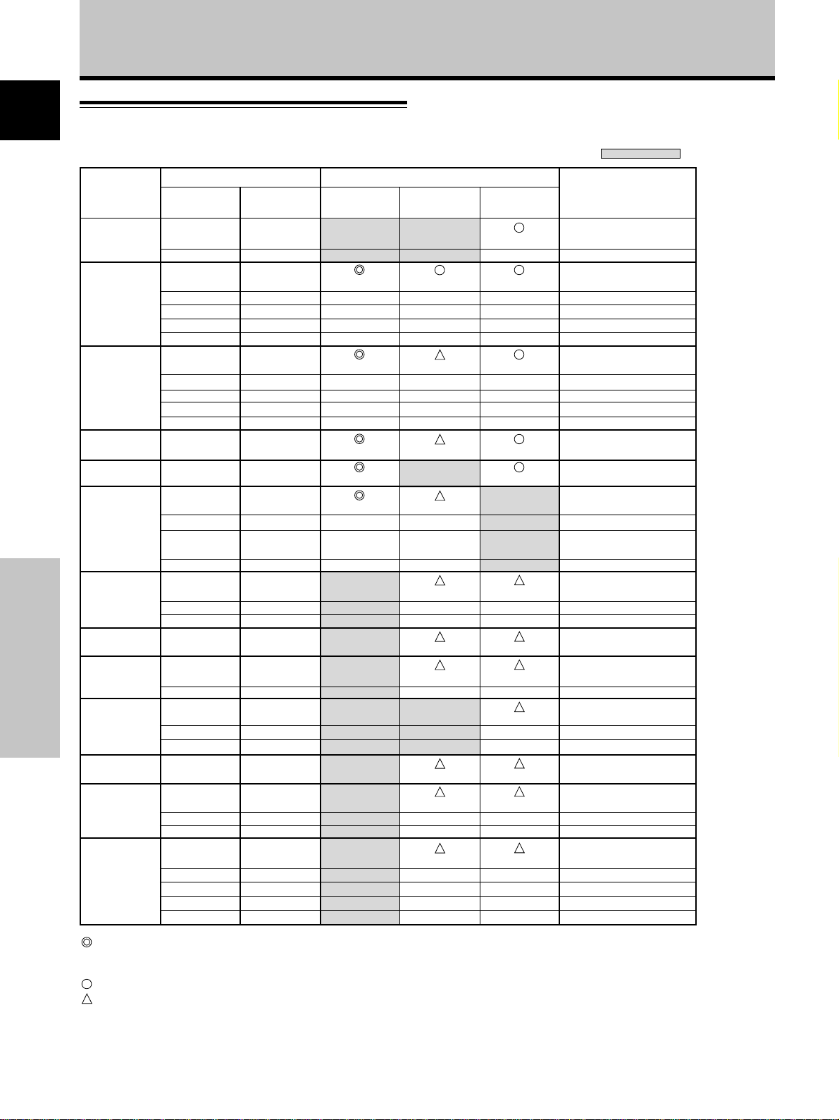
Additional Information
English
Supplement 1
-2/2: PDP-433MXE
PC signal compatibilty table (INPUT1, INPUT2)
Resolution
(Dot x Line)
640x400
640x480
800 x600
832x624
852x480
1024x768
1152x864
1152x870
1152x900
Additional Information
1280x768
1280x960
1280x1024
1600 x 1200
: Input signal and screen's dot x line ratio are made to display at 1:1 ratio.
Note: The PDP-433MXE is designed with horizontally oblong elements, with the result
: Picture will be enlarged but some fine detail will be hard to see.
: Simple reproduction. Fine detail will not be reproduced. Screen size will be displayed as
“~ (TYPE)”.
that the image displayed will appear more oblong than the original input signal.
Refresh rate
Vertical DOT BY DOT
56.4Hz
70.1Hz
60Hz
66.7Hz
72Hz
75Hz
85Hz
56Hz
60Hz
72Hz
75Hz
85Hz
74.6Hz
60Hz
60Hz
70Hz
75Hz
(74.9Hz)
85Hz
60Hz
72Hz
75Hz
75.1Hz
66.0Hz
76.0Hz
56Hz
60Hz
70Hz
60Hz
60Hz
75Hz
85Hz
60Hz
65Hz
70Hz
75Hz
85Hz
Horizontal
24.8kHz
31.5kHz
31.5kHz
35.0kHz
37.9kHz
37.5kHz
43.3kHz
35.2kHz
37.9kHz
48.1kHz
46.9kHz
53.7kHz
49.7kHz
31.7kHz
48.4kHz
56.5kHz
60.0kHz
(60.2kHz)
68.7kHz
53.7kHz
64.9kHz
67.7kHz
68.7kHz
61.8kHz
71.7kHz
45.1kHz
48.4kHz
55.5kHz
60.0kHz
64.0kHz
80.0kHz
91.1kHz
75.0kHz
81.3kHz
87.5kHz
93.8kHz
106.3kHz
Screen size (Dot x line)
640x480
±
±
±
±
800x600
±
±
±
±
832x624
852x480
1024x768
±
±
±
4:3
768x768
±
±
±
±
768x768
±
±
±
±
768x768
768x768
±
±
±
768x768
±
±
768x768
738x768
±
768x768
720x768
±
±
768x768
±
±
±
±
FULL
1024x768
±
1024x768
±
±
±
±
1024x768
±
±
±
±
1024x768
1024x768
1024x768
±
±
1024x768
1024x768
±
1024x768
±
±
1024x768
1024x768
±
±
1024x768
±
±
±
±
: Not available.
Remarks
NEC PC-9800
NEC PC-9800
(852x480)
(864x480)
Apple Macintosh 13”
(1072x600)
Apple Macintosh 16”
(1376x768)
( ) indicates Apple
Macintosh 19”
Apple Macintosh 21”
Sun Microsystems LO
Sun Microsystems HI
(1600x1024)
36
En
Page 41

Additional Information
Supplement 2
Signal assignment of INPUT 1 (Mini D-sub 15 pin
socket connector)
51
6
+
+
+
+
+
+
+
+
NC (No connection)
+
+
NC (No connection)
+
+
NC (No connection)
Pin No.
1
2
3
4
5
6
7
8
9
10
11
12
13
14
15
10
15 11
Input Output
R or CR/PR
G or Y
B or CB/PB
NC (No connection)
GND
GND
GND
GND
DDC + 5V
GND
NC (No connection)
DDC SDA
HD or H/V SYNC
VD
DDC SCL
Explanation of Terms
Aspect ratio
The TV screen’s width to height ratio is referred to as its aspect
ratio. The aspect ratio on standard TVs is 4:3 and on wide TVs or
High Definition TVs it is 16:9.
G ON SYNC
This indicates a video signal in the form of a synchronization
signal added to the G (GREEN) signal of the R.G.B signal.
VGA
VGA is short for “Video Graphics Array”.
Generally this indicates a 640 dot x 480 line resolution.
XGA
General term for “eXtended Graphics Array”.
Generally this indicates a 1024 dot x 768 line resolution.
English
Apple and Macintosh are registered trademarks of Apple
Computer, Inc.
Microsoft is a registered trademark of Microsoft Corporation.
NEC and PC-9800 are trademarks of NEC Corporation.
VESA and DDC are registered trademarks of Video Electronics
Standards Association.
Power Management and Sun Microsystems are registered
trademarks of Sun Microsystems, Inc.
VGA and XGA are registered trademarks of International
Business Machines Co., Inc.
E
NERGY STAR
is a U.S. registered mark.
Additional Information
37
En
Page 42

Published by Pioneer Corporation.
Copyright © 2002 Pioneer Corporation.
All rights reserved.
38
En
Page 43

Mode d’emploi
Nous vous remercions vivement d’avoir fait l’acquisition de
ce produit PIONEER.
Avant d’utiliser votre écran à plasma, veuillez lire
attentivement les “Précautions de Sécurité” ainsi que la
présente “Mode d’emploi” de manière à utiliser l’ecran à
plasma correctement.
Conservez ce manuel dans un endroit sûr. Il vous sera
sûrement utile dans les mois ou les années qui suivent.
Français
Remarques sur l’installation:
Ce produit est vendu en assumant qu’il sera installé par un
personnel suffisamment expérimenté et qualifié. Faites toujours
réaliser le montage et l’installation par un spécialiste ou par votre
revendeur.
PIONEER ne peut être tenu responsable pour tout dommage
causé par une erreur d’installation ou de montage, une mauvaise
utilisation ou un désastre naturel.
Remarque pour le revendeur:
Après l’installation, assurez-vous de remettre ce mode d’emploi
à l’utilisateur et de lui expliquer comme utiliser ce produit.
Précautions de Sécurité
i
Fr
Page 44

Précautions de Sécurité
Français
AVERTISSEMENT: EN POSITIONNANT
L’EQUIPEMENT, S’ASSURER QUE LA FICHE ET LA PRISE DE
RACCORDEMENT DE L’ALIMENTATION SONT FACILEMENT
ACCESSIBLES.
Pour garantir un rayonnement thermique adéquat, placer l’unité
à une certaine distance des autres équipements, murs, etc.
(normalement à une distance supérieure à 10 cm). Eviter les
modes d’installation décrits ciaprès qui entraînent l’obstruction
des orifices et provoquent une accumulation de chaleur interne,
d’où un risque d’incendie.
• Ne pas essayer de placer l’unité dans des espaces réduirts et
mal ventilés
• Ne pas la placer sur un tapis
• Ne pas la recouvrir d’un tissu etc.
• Ne pas la placer sur le côté
• Ne pas la renverser
• Si une installation spéciale est envisagée, comme un montage
à proximité immédiate du mur, un placement horizontal,
Précautions de Sécurité
consulter d’abord le revendeur Pioneer de votre région.
Les symboles qui suivent se trouvent sur les
étiquettes apposées sur le produit. Ils alertent
les utilisateurs de ce matériel ainsi que le
personnel du service aprésvente sur toutes les
situations qui présentent un danger potentiel.
DANGER
Ce symbole concerne un risque ou une
pratique dangereuse qui peut entraîner des
blessures graves ou la mort.
ATTENTION
Ce symbole concerne un risque ou une
pratique dangereuse qui peut entraîner des
blessures ou des dégâts matériels.
Conditions de Fonctionnement H045 Fr
Tempéraure et humidité ambiante lors du fonctionnement:
0 °C – +40 °C (+32 °F – +104 °F); inférieur à 85 %RH (events
d’aération non obstrués)
Ne pas installer dans les lieux suivants
÷ Lieux exposés à la lumière direct du soleil ou lumière
artificielle forte
÷ Lieux exposés à une forte humidité ou lieux peu ventilés
ii
i
Fr
Page 45

Table des matières
Précautions de Sécurité....................................................... i
Particularités........................................................................ 2
Avant de commencer.......................................................... 3
Comment utiliser ce mode d’emploi ...................................................... 3
Vérification des accessoires fournis ....................................................... 5
Les différents organes et leurs rôles ......................................
Appareil .................................................................................................... 6
Télécommande ........................................................................................ 7
Panneau de raccordement ...................................................................... 8
Installation et raccordements .......................................... 10
Installation de l’écran à plasma ............................................................ 10
Raccordements de INPUT1 et INPUT2 ................................................. 12
Raccordements audio ............................................................................ 14
Raccordement du cordon de commande
d’ensemble ............................................................................................. 15
Raccordement du cordon d’alimentation ............................................ 15
Comment faire cheminer les câbles ..................................................... 16
Mise en œuvre de l’ensemble .......................................... 17
Mise en œuvre après raccordement .................................................... 17
Fonctionnement ................................................................ 19
Choix de la source ................................................................................. 19
Choix du format de l’image .................................................................. 21
Agrandissement partiel de l’image (POINT ZOOM) ............................ 23
Mise hors tension automatique ............................................................ 24
Français
6
Réglages de l’écran à plasma........................................... 25
Réglage de la qualité de l’image .......................................................... 25
Réglage automatique de la position de l’image et de l’horloge ........ 26
Réglage manuel de la position d’écran et de l’horloge ...................... 27
Autres démarches ............................................................. 28
Modification de l’affichage d’entrée (INPUT LABEL) .......................... 28
Fonction “Power Control” (Gestion de courant) ................................. 29
Fonctionnement automatique (AUTO FUNCTION) ............................. 29
Sortie audio (AUDIO OUT) .................................................................... 30
Informations complémentaires ....................................... 31
Nettoyage ............................................................................................... 31
Guide de dépannage ............................................................................. 31
Caractéristiques techniques .................................................................. 34
Supplément 1 ......................................................................................... 35
Supplément 2 ......................................................................................... 37
Glossaire ................................................................................................. 37
Avant de commencer
1
Fr
Page 46

Particularités
PDP-503MXE PDP-433MXE
¶ Découvrez le large panneau à plasma XGA de 50
pouces de conception nouvelle
Produisant des images plus claires et nettes dont le contraste est
élevé, le nouvel écran à plasma XGA large de 50 pouces et de
haute précision (1280x768 / 16:9) surpasse les écrans antérieurs
à haute luminance.
Français
Nouveau filtre d’écran total, produisant des images
claires et contrastées, même dans une salle éclairée.
Le nouveau filtre d’écran total supprime les reflets de la surface,
fournissant des images claires et contrastées, même si le local
est éclairé. Les composants de fréquence superflus des signaux
RVB sont supprimés aussi, ce qui rehausse fortement la
restitution des couleurs.
¶ Large gamme de formats de signaux informatiques
L'écran supporte l'affichage non compressé de signaux allant de
640x400 et 640x480 (VGA) à 1024x768 (XGA) et 1280x768, ainsi
que l'affichage compressé de signaux de 1280x1024 (SXGA) et
1600x1200 (UXGA). De plus, les réglages de rapport largeur /
hauteur et de taille d'écran supportés comprennent Dot-by-Dot,
4:3, FULL et PARTIAL*1.
*1 L'aspect du rapport largeur / hauteur et de la taille d'écran
varie selon le signal d'entrée.
¶ Configuration d’installation plus libre
Possibilités élargies d’installation par un solide
design plus mince et plus léger
Bien qu'il fournisse une image de 50", cet écran n’a que 98 mm
d’épaisseur et il pèse seulement 38,9 kg. Et sa conception
dissipant efficacement la chaleur améliore les conditions de
fonctionnement. Associé à une construction solide, le design
mince et léger élargit considérablement l’éventail des
emplacements et des modes d’installation.
¶ Haute fiabilité pour des applications commerciales
Cet écran est très fiable et particulièrement approprié pour des
applications commerciales. Il permet notamment de supprimer la
luminance de crête en fonction du programme transmis et il
change la vitesse de son ventilateur en accord avec les
fluctuations de l’environnement de travail. Ces fonctions
assurent une sécurité et une endurance élevées lors
d'utilisations commerciales.
¶ Commodité accrue
La commodité est renforcée par l’inclusion de fonctions qui
rendent l’écran encore plus compatible avec votre ordinateur.
Citons la fonction AUTO SETUP (configuration automatique) de
réglage simplifié pour les branchements sur l’ordinateur et la
Avant de commencer
fonction POINT ZOOM (agrandissement partiel de l’image),
permettant d’afficher les détails précis d’une image sur l’écran.
¶ Économie d’énergie
Bien qu'il soit équipé d'un panneau de haute précision
(1280x768), cet appareil réalise la plus haute économie d'énergie
de tous ceux de sa classe (classe XGA de 50 pouces: 380 W, soit
20% de moins que les produits Pioneer précédents). De plus,
lorsque la fonction Gestion de courant (Power Control) est en
service, la consommation électrique est réduite de 20% en
comparaison de celle d'un fonctionnement en mode normal
(MODE 1, avec entrée de signal de barre colorée).
¶ Options disponibles (vendues séparément)
(Pour de plus amples détails concernant ces options,
consultez le revendeur.)
1 Support de bureau : Support pour écran PDP-503MXE / PDP-
2 Suspension murale :
3 Enceintes acoustiques spécialement conçues pour les écrans à
plasma (largeur: 7,4 cm)
:
Adoption d’un système vertical à 2 voies, composé d’un hautparleur d’aigus conique à dôme de 2,5 cm et de nouveaux
haut-parleurs de forme ovale d’une largeur de 4,5 cm,
disposés verticalement. (Lorsque les hauts-parleurs sont fixés
sur l’écran, le panneau de commande de l’appareil devient
indisponible.)
433MXE
Applique d’installation murale, conçue
comme support de fixation de l’appareil.
¶ Découvrez le large panneau à plasma de 43 pouces
Produisant des images plus claires et nettes dont le contraste est
élevé, le nouvel écran à plasma large de 43 pouces et de haute
précision (1024x768 / 16:9) surpasse les écrans antérieurs à
haute luminance.
Le nouveau filtre d’écran total supprime les reflets de la surface,
fournissant des images claires et contrastées, même si le local
est éclairé. Les composants de fréquence superflus des signaux
RVB sont supprimés aussi, ce qui rehausse fortement la
restitution des couleurs.
¶ Large gamme de formats de signaux informatiques
L'écran supporte l'affichage non compressé de signaux allant de
640x400 et 640x480 (VGA) à 1024x768 (XGA), ainsi que
l'affichage compressé de signaux de 1280x1024 (SXGA) et
1600x1200 (UXGA). De plus, les réglages de rapport largeur /
hauteur et de taille d'écran supportés comprennent Dot-by-Dot,
4:3 et FULL*1.
*1 L'aspect du rapport largeur / hauteur et de la taille d'écran
¶ Configuration d’installation plus libre
Bien qu'il fournisse une image de 43", cet écran n’a que 98 mm
d’épaisseur et il pèse seulement 31,5 kg. Et sa conception
dissipant efficacement la chaleur améliore les conditions de
fonctionnement. Associé à une construction solide, le design
mince et léger élargit considérablement l’éventail des
emplacements et des modes d’installation.
¶ Haute fiabilité pour des applications commerciales
Cet écran est très fiable et particulièrement approprié pour des
applications commerciales. Il permet notamment de supprimer la
luminance de crête en fonction du programme transmis et il
change la vitesse de son ventilateur en accord avec les
fluctuations de l’environnement de travail. Ces fonctions
assurent une sécurité et une endurance élevées lors
d'utilisations commerciales.
¶ Commodité accrue
La commodité est renforcée par l’inclusion de fonctions qui
rendent l’écran encore plus compatible avec votre ordinateur.
Citons la fonction AUTO SETUP (configuration automatique) de
réglage simplifié pour les branchements sur l’ordinateur et la
fonction POINT ZOOM (agrandissement partiel de l’image),
permettant d’afficher les détails précis d’une image sur l’écran.
¶ Économie d’énergie
Bien qu'il soit équipé d'un panneau de haute précision
(1024x768), cet appareil réalise la plus haute économie d'énergie
de tous ceux de sa classe (classe de 43 pouces: 298 W). De
plus, lorsque la fonction Gestion de courant (Power Control) est
en service, la consommation électrique est réduite de 20% en
comparaison de celle d'un fonctionnement en mode normal
(MODE 1, avec entrée de signal de barre colorée).
4 Carte vidéo :
5 Cache de câble :
de conception nouvelle
Nouveau filtre d’écran total, produisant des images
claires et contrastées, même dans une salle éclairée.
varie selon le signal d'entrée.
Possibilités élargies d’installation par un solide
design plus mince et plus léger
Cette carte d’expansion permet de regarder
des signaux vidéo et des signaux RVB
numériques d’ordinateur (conformes à DVI).
Ce cache spécial permet de dissimuler
proprement les branchements de câbles à
l’arrière.
En tant que partenaire de ENERGY STAR®, Pioneer
Corporation affirme que cet appareil respecte les
directives du programme ENERGY STAR®, en ce qui
concerne l’efficacité énergétique.
2
Fr
Page 47

Avant de commencer
Comment utiliser ce mode d’emploi
Ce mode d’emploi s’organise autour d’explications
classées dans l’ordre qui nous a paru le plus logique à
quelqu’un qui prendrait possession de l’écran à plasma
pour la première fois.
Après avoir retiré l’écran à plasma de son emballage et
vous être assuré que toutes les accessoires sont
présents, nous vous suggérons de lire la section “Les
différents organes et leurs rôles” qui débute à la page 6
de manière à vous familiariser avec les organes et les
commandes de l’écran à plasma et de sa télécommande.
La section “Installation et raccordements” qui débute à la
page 10, couvre tous les aspects de l’installation de
l’écran à plasma et des raccordements à effectuer avec
les autres appareils de l’installation.
La section “Mise en oeuvre de l’ensemble” qui débute à
là page 17 traite des réglages à réaliser à partir des
menus affichés de façon à intégrer le fonctionnement de
l’écran à plasma à celui des autres appareils de
l’installation. En fonction des raccordements réalisés, il
peut être inutile de lire cette section.
Les autres sections de ce mode d’emploi abordent des
opérations de base telle le choix d’une source et des
opérations plus détaillées telles que l’affichage d’image
correspondant aux appareils utilisés et aux goûts
personnels.
Affichages d’écran
Les affichages d’écran, présentés à titre d’exemples dans
ce manuel, concernent le modèle PDP-503MXE.
L’affichage du PDP-433MXE diffère comme suit:
Exemple d’Affichage d’écran du PDP-503MXE:
÷ L’affichage d’écran du PDP-503MXE présente un bord
non apparent sur chaque côté.
MAIN MENU INPUT1
PICTURE SCREEN SET UP OPTION
CONT RAS T
BR
IGHT.
RLEVEL
.
GLEVEL.
BLEVEL.
H E NHANCE.
V E NH ANCE.
RSETE
SELECT ENTER EXIT
Exemple d’Affichage d’écran du PDP-433MXE:
÷ L’Affichage d’écran du PDP-433MXE remplit la zone
d”affichage dans le sens horizontal.
MAIN MENU INPUT1
PICTURE SCREEN SET UP OPTION
CONT RAS T
BR
IGHT.
RLEVEL
.
GLEVEL.
BLEVEL.
H ENH ANCE.
V E NHAN CE.
RSETE
:
0
:
0
:
+
6
0
:
+
60
:
+
60
:
0
:
0
SET
:
0
:
0
:
+
0
6
:
+
60
:
+
60
:
0
:
0
MENU
Français
SELECT ENTER EXIT
SET
MENU
Notez que le contenu affiché réel est le même pour le
PDP-503MXE et le PDP-433MXE.
Avant de commencer
3
Fr
Page 48

Avant de commencer
Description des modes
opératoires
Les modes opératoires sont présentés sous la forme
d’étapes numérotées. La plupart sont rédigés en tenant
Français
compte des possibilités de la télécommande, à moins
que la touche ou la commande ne soient présentes que
sur l’écran à plasma. A noter qu’une touche ou une
commande de l’écran à plasma ayant le même nom
qu’une touche ou une commande de la télécommande,
jouent les mêmes rôles.
Ce qui suit est un exemple de démarches réelles,
expliquant comment ajuster la position verticale et
horizontale de l’image sur l’écran. Les illustrations
permettent de vérifier visuellement que les étapes se
déroulent bien comme il convient. Examinez cet exemple
avant de poursuivre la lecture du mode d’emploi.
1 Appuyez sur la touche MENU pour afficher la page
de menu.
MAIN MENU INPUT1
PICTURE SCREEN SET UP OPTION
CONT RAS T
BR
IGHT.
RLEVEL
.
GLEVEL.
BLEVEL.
H E NHANCE.
V E NH ANCE.
RSETE
SELECT ENTER EXIT
:
0
:
0
:
+
6
0
:
+
60
:
+
60
:
0
:
0
SET
MENU
2 Utilisez les touches 3 pour choisir l’option
SCREEN.
Avant de commencer
MAIN MENU INPUT1
PICTURE SCREEN SET UP OPTION
POS I T I ON
CL OC HASEK/ /
RSETE
:
00
/
:
P
00
3 Utilisez les touches 5/∞ pour choisir le paramètre
à modifier.
MAIN MENU INPUT1
PICTURE SCREEN SET UP OPTION
POS I T I ON
CL OC HASEK/ /
RSETE
SELECT ENTER EXIT
:
00
/
:
P
SET
00
MENU
4 Appuyez sur la touche SET pour afficher les
valeurs possibles pour le paramètre choisi.
POH. S I T I ON
POV. S I T I ON
:
0
:
0
MENU
SELECT ENTER EXIT
SET
MENU
ADJUST
EXIT
SET
SET
5 Utilisez les touches 5/∞/2/3 pour choisir la
valeur désirée.
Remarque
Les affichages d’écran illustrés dans ce manuel ne sont
présentés qu’à titre d’exemples. Le contenu réel et les rubriques
affichées en réalité peuvent être différents en fonction de la
source d’entrée et des réglages particuliers.
4
Fr
Page 49

Avant de commencer
Vérification des accessoires
fournis
Assurez-vous que les accessoires suivants font partie de
la fourniture.
1 Boîtier de télécommande
2 2 piles AA (R6)
3 Chiffon de nettoyage (pour essuyer l’écran)
7 2 supports pour l’écran
Français
8 2 rondelles (petite)
9 2 boulons hexagonaux
0 Support pour télécommande
4 2 colliers rapides
5 2 serre-câble
6 Noyau en ferrite
- Attache de câble
÷ Mode d’emploi
Utilisez ce support
pour y ranger la
télécommande. Si vous
fixez ce support à
l’arrière de l’écran,
veiller à ne pas
obstruer les ouïes
d’aération.
Avant de commencer
5
Fr
Page 50

Français
Les différents organes et leurs rôles
Appareil
Panneau de commande de l’écran à plasma
ôles
Appareil
1 Support pour l’écran
Appareil
3
1
2
4
5
6
7
8
9
0
Remarque
Lorsque les enceintes sont montées sur l’écran
à plasma, le panneau de commande devient
indisponible.
6 Touche MENU
Appuyez sur cette touche pour ouvrir ou fermer les
menus s’affichant sur l’écran (pages 17 à 30).
2 Capteur de télécommande
Dirigez le faisceau de télécommande vers ce capteur
(page 8).
Les différents organes et leurs r
3 Témoin STANDBY/ON
Lorsque l’écran à plasma est en veille, ce témoin est
de couleur rouge; il s’éclaire de couleur vert quand
l’écran à plasma est en fonctionnement (page 19).
Il clignote en vert lorsque la fonction POWER
MANAGEMENT (Gestion de courant) est en service
(page 24).
Le motif du clignotement permet aussi d’indiquer des
messages d’erreur (page 33).
Panneau de commande de l’écran à plasma
4 Touche STANDBY/ON
Appuyez sur cette touche pour mettre l’écran en
service ou en veille (page 19).
5 Touche INPUT
Appuyez sur cette touche pour choisir le signal
d’entrée (page 19).
6
Fr
7 Touche ADJUST (5/∞/3/2)
Utilisez ces touches pour naviguer dans les menus et
choisir des valeurs de réglage.
L’usage de ces touches est clairement indiqué sur les
pages de menu affichées sur l’écran (pages 17 à 30).
8 Touche SET
Appuyez sur cette touche pour définir une valeur ou
valider un choix (pages 17 à 30).
9 Touche SCREEN SIZE
Appuyez sur cette touche pour choisir le format de
l’image (page 21).
0 Touche AUTO SET UP
Si vous utilisez l’entrée d’un signal d’ordinateur, cette
touche ajuste automatiquement les paramètres
POSITION et CLOCK/PHASE (horloge/phase) aux
valeurs optimales (page 26).
Page 51

Télécommande
1
2
3
4
5
6
Manipulation du boîtier de
télécommande
¶ Ne laissez pas tomber le boîtier, ne le heurtez
pas.
¶ N’utilisez pas le boîtier de télécommande en
plein soleil, près d’un appareil de chauffage,
dans une atmosphère très humide.
¶ Si la portée de la télécommande a
sensiblement diminué, cela veut dire que les
piles sont usagées. Remplacez alors les piles
dès que possible.
7
8
9
0
-
Les différents organes et leurs rôles
1 Touche SCREEN SIZE
Appuyez sur cette touche pour choisir le format de l’image (page
21).
2 Touches INPUT
Utilisez ces touches pour choisir le signal d’entrée (page 19).
3 Touche MENU
Appuyez sur cette touche pour ouvrir ou fermer les menus
s’affichant sur l’écran (pages 17 à 30).
4 Touches ADJUST (5/∞/3/2)
Utilisez ces touches pour naviguer dans les menus et choisir des
valeurs de réglage.
L’usage de ces touches est clairement indiqué sur les pages de
menu affichées sur l’écran (pages 17 à 30).
5 Touche SET
Appuyez sur cette touche pour définir une valeur ou valider un choix
(pages 17 à 30).
6 Touche MUTING
Appuyez sur cette touche pour couper les sons (page 20).
7 Touche AUTO SET UP
Si vous utilisez l’entrée d’un signal d’ordinateur, cette touche ajuste
automatiquement les paramètres POSITION et CLOCK/PHASE
(horloge/phase) aux valeurs optimales (page 26).
8 Touche STANDBY/ON
Appuyez sur cette touche pour mettre l’écran en service ou en veille
(page 19).
9 Touche DISPLAY
Appuyez sur cette touche pour afficher le nom de l’entrée et de
mode de fonctionnement actuels (page 20).
0 Touche POINT ZOOM
Utilisez cette touche pour choisir et agrandir une partie de l’écran
(page 23).
- Touches VOLUME (+/–)
Utilisez ces touches pour régler le niveau d’écoute (page 20).
Français
ôles
Les différents organes et leurs r
Mise en place des piles de la
télécommande
Tout en appuyant sur le couvercle, faitesle glisser dans le sens de la flèche.
2 piles AA (R6)
ATTENTION
¶ Veillez à respecter les indications de polarité (+ et –) gravées
dans le logement des piles.
¶ N’utilisez pas tout à la fois une pile neuve et une pile usagée.
Remplacez les deux piles en même temps.
¶ Certaines piles identiques par leur taille, diffèrent par leur
tension. N’utilisez pas deux types de pile différent.
¶ Pour éviter que le boîtier de télécommande ne soit
endommagé par une fuite de l’électrolyte des piles, retirez-en
les piles si vous envisagez de ne pas l’utiliser pendant un mois
environ. Si les piles ont fuit, nettoyez soigneusement le
logement et utilisez un jeu de piles neuves.
¶ Ne chargez pas les piles ordinaires, ne les court-circuitez pas,
ne les jeter pas dans une flamme vive.
Lorsque vous diposez de piles / batteries usées, veuillez vous
conformer aux normes gouvernementales ou environnementales
en vigueur dans votre pays ou région.
H048 Fr
7
Fr
Page 52
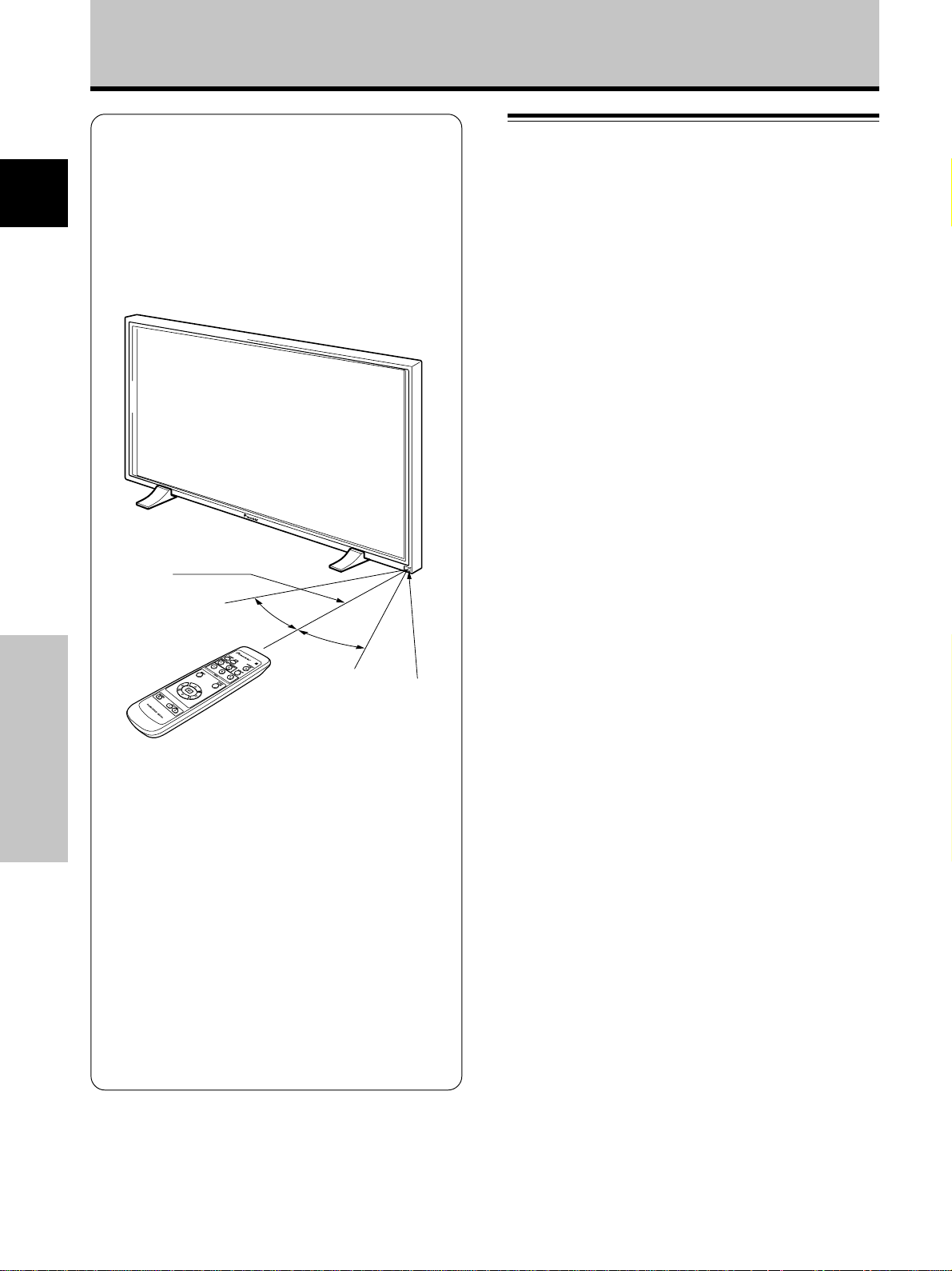
Les différents organes et leurs rôles
Portée de fonctionnement de la
télécommande
Pour utiliser la télécommande, dirigez-la vers le capteur
Français
(Î) situé sur la face avant de l’écran. La portée de la
télécommande va jusqu’à 7 mètres à un angle de 30˚
maximum de part et d’autre de l’axe du capteur.
7 m
ôles
En cas de difficulté à l’emploi de la
télécommande
¶ La télécommande risque de ne pas fonctionner si son
Les différents organes et leurs r
faisceau est interrompu par un objet placé devant l’écran.
¶ La portée de la télécommande diminue à mesure que les
piles se déchargent. Remplacez le plus tôt possible les
piles dès qu’elles sont usées.
¶ L’écran à plasma émet des rayons infrarouges. Si une
platine vidéo ou un autre composant, contrôlé par une
télécommande à infrarouge, est placé près de cet appareil,
la réception des signaux de la télécommande peut en être
perturbée ou rendue impossible. Dans ce cas, éloignez le
composant par rapport à l’écran à plasma.
¶ Selon les conditions d’installation, les rayons infrarouges,
émis par l’écran à plasma, peuvent perturber le
fonctionnement ou réduire la portée de la télécommande.
La puissance des rayons infrarouges, émis par l’écran, varie
selon l’image affichée.
30˚
30˚
Panneau de raccordement
Le panneau de raccordement comporte deux connecteurs
d’entrée vidéo et un connecteur de sortie vidéo. Des
jacks d’entrée audio et de sortie de haut-parleurs sont
également prévus, ainsi qu’un connecteur CONTROL IN/
OUT pour le raccordement d’autres appareils PIONEER,
portant la marque [Î].
Pour des explications sur les branchements, consultez les
pages indiquées entre parenthèses.
1 Borne SPEAKER (R)
Pour le raccordement à l’enceinte droite. Cette
enceinte doit présenter une impédance comprise
entre 8 et 16 Ohms (page 14).
2 CONTROL IN/OUT (mini-prises monaurales)
Utilisez ces prises pour le raccordement de l’écran à
plasma à d’autres appareils PIONEER portant la
marque Î . Cela fait, cet écran peut être considéré,
du point de vue des commandes, comme faisant
partie de l’ensemble (page 15).
3 COMBINATION IN/OUT
NE BRANCHEZ AUCUN APPAREIL SUR CES
PRISES.
Ces prises sont utilisées pour effectuer des réglages
en usine.
Capteur
4 RS-232C
NE BRANCHEZ AUCUN APPAREIL SUR CETTE
PRISE.
Cette prise est utilisée pour effectuer des réglages en
usine.
5 INPUT1 (mini-prise D-sub à 15 broches)
Utilisez ces prises pour le branchement d’un
ordinateur personnel (PC) ou d’un appareil similaire.
Choisissez la prise en fonction de la nature du signal
fourni par l’appareil connecté (pages 12 à 14).
6 OUTPUT (INPUT1) (mini-prise D-sub à 15 broches)
Utilisez la prise OUTPUT (INPUT1) pour appliquer le
signal vidéo sur un monite ur extérieur ou un autre
appareil.
Remarque: Le signal vidéo n’est pas présent sur la
prise OUTPUT (INPUT1) lorsque l’écran à plasma est
hors tension ou en veille (page 13).
7 INPUT2 (prises BNC)
Utilisez ces prises pour le branchement d’un
ordinateur personnel (PC) ou d’un appareil similaire.
Choisissez la prise en fonction de la nature du signal
fourni par l’appareil connecté (pages 12 à 14).
8
Fr
Page 53

Cette illustration présente le modèle PDP-503MXE.
Les différents organes et leurs rôles
Français
COMBINATION
8Ω ~16Ω
SPEAKER
R
+ –
1
CONTROL
IN OUT
IN OUT
23 4
RS-232C
8 Sélecteur d’impédance du signal de synchronisation
Selon le raccordement de la prise INPUT2, il peut être
nécessaire de modifier la position de ce sélecteur de
manière à adapter l’appareil à l’impédance de sortie du
signal de synchronisation.
Si l'impédance de sortie du signal de synchronisation
du composant est inférieure à 75 Ohms, placez ce
sélecteur sur la position 75 Ω (pages 12 et 14).
9 AUDIO INPUT (Mini-prise stéréo)
Utilisez cette prise pour disposer des sons appliqués
sur INPUT1 ou INPUT2.
Branchez sur cette prise la sortie son de l’appareil relié
à INPUT1 ou INPUT2 (page 14).
AC INLET
8Ω ~16Ω
SPEAKER
+ –
L
~=-
INPUT1
ANALOG RGB (ANALOG RGB)
5 678
(ON SYNC) (H/V SYNC)
OUTPUT
GBRHDVD
INPUT2 AUDIO
75 2.2
Ω kΩ
INPUT
(INPUT1/2)
Ô
9
- Interrupteur MAIN POWER
Utilisez cet interrupteur pour mettre l’écran à plasma
sous tension ou hors tension.
= AC INLET
Utilisez cette prise pour connector un cordon
d’alimentation à une prise secteur (page 15).
~ Borne SPEAKER (L)
Pour le raccordement à l’enceinte gauche. Cette
enceinte doit présenter une impédance comprise
entre 8 et 16 Ohms (page 14).
OUTPUT
0
ôles
Les différents organes et leurs r
0 AUDIO OUTPUT (Mini-prise stéréo)
Utilisez cette sortie pour appliquer à un amplificateur
audiovisuel ou un appareil similaire, les sons
provenant de l’appareil source qui est relié à cet écran
à plasma (page 14).
9
Fr
Page 54

Installation et raccordements
Installation de l’écran à plasma
Installation de l’écran à plasma sur les supports
fournis
Français
Fixez les supports sur la surface d’installation.
Utilisez des boulons M8 disponibles dans le commerce,
dont la longueur est supérieure de 25 mm à l’épaisseur
de la surface d’installation.
1 Au moyen de boulons M8 disponibles dans le
commerce, assurez la fixation des supports fournis
à la surface d’installation préalablement percées
de 4 trous convenables.
Avant
PDP-503CMX: 798 mm
PDP-433CMX: 768 mm
Arrière
3 Assurez la fixation de l’écran à plasma au moyen
de la rondelle et du boulon fournis.
Pour serrer, utilisez une
clé hexagonale de 6 mm.
110 mm
2 Posez l’écran à plasma dans les supports.
Installation et raccordements
ATTENTION
Comme cet écran d’affichage pèse au moins 30 kg et qu’il est
très instable lorsqu’il est dressé sur son côté, nous conseillons
que le déballage, le transport et l’installation soient effectués par
2 personnes au moins.
10
Fr
Page 55

Installation et raccordements
Installation à l’aide du support ou de la fixation
PIONEER en option
÷ Que ce soit à l’aide du support ou de la fixation, l’installation
de l’écran à plasma doit être réalisée par un technicien
compétent ou par le revendeur.
÷ Lors de l’installation, utilisez les boulons fournis avec le
support ou la fixation.
÷ Pour de plus amples détails concernant l’installation, reportez-
vous aux instructions qui accompagnent le support ou la
fixation.
Installation à l’aide d’accessoires autres que le
support ou la fixation PIONEER (vendus
séparément)
÷ Dans toute la mesure du possible, utilisez des pièces et des
accessoires fabriqués par PIONEER. PIONEER ne pourra être
tenue responsable des accidents et dommages qui
résulteraient de l’utilisation de pièces ou d’accessoires
fabriqués par des tiers.
÷ Pour effectuer une installation personnalisée, consultez le
revendeur ou un technicien compétent.
Ouïes d’aération (ventilateur)
Perçage b
Perçage b
Accrochage de l’écran à plasma à un mur
L’écran à plasma possède des perçages destinés à
permettre sa fixation sur un mur, etc. Les perçages qui
peuvent être utilisés sont indiqués sur le schéma cidessous.
Français
÷ L’écran à plasma doit être maintenu en 4 points
(minimum) placés au-dessus et au-dessous de l’axe
horizontal, et à droite et à gauche de l’axe vertical.
÷ Dans le cas des perçages a et b, utilisez des boulons
dont la longueur est telle qu’ils pénètrent dans l’écran à
plasma de 12 mm au moins et de 18 mm au plus.
Reportez-vous à la vue de côté ci-dessous.
÷ L’écran à plasma est muni d’une vitre qui interdit sa
pose sur une surface qui n’est pas plane.
ATTENTION
Pour éviter toute anomalie de fonctionnement, une
surchauffe de l’écran à plasma et un incendie, veillez,
en fin d’installation, à ce que les ouïes d’aération ne
soient pas obstruées. Par ailleurs, de l’air chaud étant
évacué par les ouïes d’aération, l’accumulation de
poussières sur la surface d’installation et sa
détérioration progressive sont à considérer.
Surface de pose
Perçage
b
Perçage
b
a hole
a hole
Axe
Vue arrière (PDP-503MXE)
Ouïes d’aération (ventilateur)
a hole
Perçage bPerçage b
a hole
Axe
Perçage b
Axe
Perçage b
Fixation,
etc.
Appareil
Perçage b
12 à 18 mm
a hole
Boulon
12 à 18 mm
Boulon
Vue de côté
ATTENTION
Assurez-vous d’utiliser un boulon M8 (pas
= 1,25 mm). (Seule cette taille de boulon
peut être utilise’e)
ATTENTION
Comme cet écran d’affichage pèse au
moins 30 kg et qu’il est très instable
lorsqu’il est dressé sur son côté, nous
conseillons que le déballage, le transport et
l’installation soient effectués par 2
personnes au moins.
Installation et raccordements
Axe
Perçage bPerçage b
Vue arrière (PDP-433MXE)
ATTENTION
L’épaisseur de cet écran à plasma est très
réduite. Veillez à ce qu’il ne puisse pas se
renverser s’il est soumis à des vibrations.
11
Fr
Page 56

Installation et raccordements
Raccordements de INPUT1 et INPUT2
Les prises INPUT1 et INPUT2 permettent le
raccordement de l’écran à un ordinateur. Ces connexions
Français
étant réalisées, ajustez les paramètres de l’écran en
fonction du signal de sortie de l’ordinateur. Pour ces
réglages, reportez-vous aux pages 17 et 18.
Prise
INPUT2
Source
extérieure
Ordinateur
personnel (PC)
avec sortie RVB
: Ne reliez rien sur cette prise. : Reliez cette prise.
Remarque
Les appareils compatibles avec INPUT1 sont également
compatibles avec INPUT2.
INPUT1 est compatible Microsoft Plug & Play (VESA DDC 1/2B).
Pour le raccordement à INPUT1, veuillez vous reporter au
supplément 2, page 37.
[ON SYNC]
GBR
G ON SYNC
GBR
R
B
RG
B
[H/V SYNC]
HD VD
H/V SYNC
HD
VD
Raccordement à un ordinateur
personnel
La méthode de raccordement dépend du type de
l’ordinateur. Avant d’effectuer les raccordements, veuillez
lire attentivement le mode d’emploi de l’ordinateur.
Avant tout raccordement veillez à ce que l’écran à plasma
et l’ordinateur soient tous deux hors tension.
Pour les signaux d’entrée PC et les tailles d’écran avec
lesquelles cet appareil est compatible, reportez-vous au
supplément 1 (pages 35 et 36).
Raccordement d’une source analogique RVB
avec signaux de synchronisation séparés
Utilisez cette possibilité si la source RVB peut fournir 5
signaux séparés: vert, bleu, rouge, synchronisation
horizontale et synchronisation verticale.
Pour le raccordement à INPUT2
(ON SYNC) (H/V SYNC)
GBRHDVD
INPUT2
75 2.2
Ô
Ω kΩ
Pour connaître les formats d’image et les signaux
d’entrée pour lesquels INPUT1 et INPUT2 sont
compatibles, reportez-vous au supplément 1 (pages 35
et 36).
Installation et raccordements
Si vous utilisez la prise INPUT2, placez le sélecteur
d’impédance de manière à adapter l’appareil à
l’impédance de sortie du signal de synchronisation.
Si l'impédance de sortie du signal de synchronisation de
l'ordinateur est inférieure à 75 Ohms, placez ce sélecteur
sur la position 75 Ω.
Un réglage général à l’aide des menus affichés sur l’écran
est nécessaire après raccordement. Reportez-vous aux
pages 17 à 18.
12
Fr
Page 57

Installation et raccordements
Pour le raccordement à INPUT1
INPUT1
ANALOG RGB (ANALOG RGB)
OUTPUT
Branchez le câble entre la prise d’entrée de l’écran à
plasma et la prise de sortie de l’ordinateur personnel.
Serrez soigneusement les vis des connecteurs à chaque
extrémité du câble.
Un réglage général à l’aide des menus affichés sur l’écran
est nécessaire après raccordement. Reportez-vous aux
pages 17 à 18.
Remarque
Selon le type de l’ordinateur, un adaptateur (fourni avec
l’ordinateur ou vendu séparément) peut être nécessaire pour
effectuer le raccordement ci-dessus.
Veuillez consulter le mode d’emploi de l’ordinateur ou le
revendeur.
Raccordement d’une source analogique RVB
fournissant le signal de synchronisation sur le
vert (G ON SYNC)
Raccordement d’une source analogique RVB fournissant
le signal de synchronisation sur le vert (G ON SYNC)
Pour le raccordement à INPUT1
INPUT1
ANALOG RGB (ANALOG RGB)
Un réglage général à l’aide des menus affichés sur l’écran
est nécessaire après raccordement. Reportez-vous aux
pages 17 à 18.
Pour le raccordement à INPUT2
(ON SYNC) (H/V SYNC)
GBRHD VD
OUTPUT
INPUT2
75 2.2
Ô
Ω kΩ
Français
Pour le raccordement à OUTPUT (INPUT1)
INPUT1
ANALOG RGB (ANALOG RGB)
OUTPUT
Vers un moniteur extérieur.
Cet écran à plasma est prévu pour que le signal vidéo
puisse être appliqu à un moniteur ou un autre appareil à
partir de la prise OUTPUT (INPUT1).
Remarque
Le signal vidéo n’est pas présent sur la prise OUTPUT (INPUT1)
lorsque l’écran à plasma est hors tension ou en veille.
Installation et raccordements
Un réglage général à l’aide des menus affichés sur l’écran
est nécessaire après raccordement. Reportez-vous aux
pages 17 à 18.
Remarque
Si vous utilisez G ON SYNC, ne branchez rien sur les prises VD
ou HD. Dans le cas contraire, l’image peut être déformée.
13
Fr
Page 58

Installation et raccordements
10 mm
Raccordement d’une source analogique RVB
fournissant des signaux composites de synchronisation
Utilisez cette solution si l’appareil fournit un signal de
synchronisation verticale placé au-dessus du signal de
synchronisation horizontale.
Français
Pour le raccordement à INPUT1
INPUT1
ANALOG RGB (ANALOG RGB)
Un réglage général à l’aide des menus affichés sur l’écran
est nécessaire après raccordement. Reportez-vous aux
pages 17 à 18.
Pour le raccordement à INPUT2
(ON SYNC) (H/V SYNC)
GBRHDVD
OUTPUT
INPUT2
75 2.2
Ô
Ω kΩ
Raccordements audio
Avant tout raccordement veillez à ce que les appareils
soient tous deux hors tension.
Raccordement des enceintes
Cet écran à plasma est doté de prises de sortie pour
enceintes acoustiques (non fournies) qui ont été
spécialement conçues pour fonctionner avec l’écran.
Avant d’effectuer un raccordement, reportez-vous aux
illustrations.
Torsadez les
brins mis à nu.
Soulevez la languette
puis introduisez le
conducteur. Abaissez la
languette pour
maintenir le conducteur
en place.
Remarque
Veillez à ne pas inverser les polarités (+) et (–) soit au niveau des
enceintes, soit au niveau de l’écran à plasma. Si les polarités sont
inversées, les sons manquent de naturel et de puissance dans
les graves.
Raccordements aux entrées audio de cet écran à
plasma
Cet écran à plasma est doté de deux entrées audio et
d’une sortie audio. Le tableau qui suit donne pour chaque
entrée vidéo les entrées audio correspondantes.
Entrée
vidéo
INPUT1
INPUT2
Prises d’entrée
audio
Mini-fiche stéréo
(G/D)
Sortie son
Les sons provenant de l’entrée
vidéo choisie sont présents sur
• Bornes SPEAKER
• les mini-prises stéréo (G/D).
Installation et raccordements
Si vous utilisez la prise INPUT2, placez le sélecteur
d’impédance de manière à adapter l’appareil à
l’impédance de sortie du signal de synchronisation.
Si l'impédance de sortie du signal de synchronisation de
l'ordinateur est inférieure à 75 Ohms, placez ce sélecteur
sur la position 75 Ω.
Un réglage général à l’aide des menus affichés sur l’écran
est nécessaire après raccordement. Reportez-vous aux
pages 17 à 18.
Remarques
÷
Si vous utilisez le signal de synchronisation composite, ne branchez
rien sur la prise VD. Dans le cas contraire, l’image peut être déformée.
÷ Certains appareils Macintosh® fournissent les signaux G ON
SYNC et de synchronisation composite. En ce cas, effectuez le
raccordement sur G ON SYNC (Voir page 13).
14
Fr
Raccordement audio pour un appareil (ordinateur)
relié à INPUT 1 ou INPUT 2
75 2.2
Ô
Ω kΩ
AUDIO
INPUT
(INPUT1/2)
OUTPUT
VD
L’entrée audio sur les
prises AUDIO INPUT
(mini-prise stéréo) est
possible pour l’appareil relié soit à INPUT1 soit à INPUT2.
Les sons sont présents sur les prises AUDIO OUTPUT
(mini-prise stéréo) ou les bornes SPEAKER, selon l’entrée
vidéo choisie.
Page 59

Installation et raccordements
Raccordement du cordon de
commande d’ensemble
Après avoir relié le cordon de commande d’ensemble, à
d’autres appareils PIONEER portant la marque Î, le
fonctionnement de ces appareils peut être commandé à
distance à partir du boîtier de télécommande fourni.
Lorsqu’un appareil est relié à l’écran à plasma par
l’intermédiaire de la prise CONTROL IN, le capteur de
télécommande de l’appareil en question devient
insensible aux signaux de télécommande. Vous devez
donc diriger le boîtier de télécommande vers le capteur
de télécommande de l’écran à plasma.
Remarques
÷ Avant tout raccordement veillez à ce que les appareils
soient hors tension.
÷ Effectuez tous les raccordements ordinaires puis les
raccordements du cordon de commande d’ensemble.
CONTROL
Appareil
CONTROL
IN OUT
IN
OUT
CONTROL
IN
OUT
Raccordement du cordon
d’alimentation
Connectez le cordon d’alimentation après que la
connexion de tous les appareils est terminée.
Caractéristique du cordon d’alimentation du
PDP-503MXE / PDP-433MXE
Cordon ........................... Aire transversale 3 x 1,0 mm
(Conformément à CEE 13)
Connecteur ................................................. 10 A, 250 V
(Conformément à EN60320, feuille C13)
Fiche ....................... À usage international (10 A, 250 V)
Exemple:
R.U. : Fiche UK 13 A avec un fusible de 13 A
(Conformément à BS1363)
Europe : 10A/16A 250V (Conformément à CEE
7,1 V)
ATTENTION
÷ Alimentez l’écran à plasma à partir de la tension prescrite
(100 - 240 Volts CA, 50/60 Hz); tout autre tension peut
provoquer un incendie ou une secousse électrique.
÷ L’écran à plasma doit être alimenté par un cordon à deux
conducteurs plus un conducteur de masse. Veillez à ce que la
prise possède une broche de mise à la terre et qu’elle soit
convenablement câblée. En cas d’utilisation d’un adaptateur, le
conducteur de masse doit tout de même être relié à la terre.
Français
2
Les cordons de
commande (non fournis)
sont prévus pour des
signaux monophoniques,
et sont munis de minifiches (sans résistance).
CONTROL
IN
OUT
Fixation du noyau du ferrite
Pour éviter les parasites, fixez le noyau en ferrite fourni
comme accessoire sur le bout à fiche du cordon
d’alimentation, comme indiqué sur l’illustration cidessous. Utilisez l’attache de câble fournie pour éviter un
glissement du noyau en ferrite sur le câble.
Noyau en ferrite
Attache de câble
À la prise
secteur
Le plus près possible
Cordon d’alimentation
À la prise
AC INLET
Installation et raccordements
15
Fr
Page 60

Installation et raccordements
Comment faire cheminer les câbles
Des colliers rapides et des serre-câble sont fournis pour
lier les câbles en tre eux. Après raccordements des
Français
appareils, procédez aux opérations qui suivent.
* Vue de l’arrière de l’écran.
1
1 Groupez les câbles en utilisant les colliers rapides
fournis.
Introduisez la partie 1 dans un des perçages à
l’arrière de l’écran à plas ma puis insérez 2 à l’arrière
de 1 pour assurer la fixation.
Les colliers rapides sont conçus pour que l’ouverture
soit difficile. Fermez-les soigneusement.
Fixation des colliers rapides à l’écran à plasma
Engagez les colliers rapides dans les trous 4 repérés
par • sur l’illustration ci-dessous.
Installation et raccordements
2
2 Liez les câbles et assurez leur maintien au moyen
des serre-câble fournis.
Remarque
Les câbles peuvent cheminer d’un côté ou de l’autre.
Cette illustration présente le modèle PDP-503MXE.
Pour retirer les colliers rapides
A l’aide d’une pince, tordez le collier de 90° puis tirez-le
vers vous. Avec le temps, le collier peut se détériorer et il
peut être nécessaire de la remplacer après que vous
l’avez retiré.
16
Fr
Page 61

Mise en œuvre de l’ensemble
VGA WIDE VGA
XGA WIDE XGA
Mise en œuvre après raccordement
Après le raccordement des appareils aux prises INPUT1
ou INPUT2, des réglages à l’aide des menus affichés sur
l’écran sont nécessaires.
Procédez aux opérations décrites ci-dessous et effectuez
les réglages en fonction des appareils connectés.
Mise en œuvre du mode écran
Remarque
Ces réglages sont nécessaires seulement lorsque sont utilisées les
fréquences de rafraîchissement de signal d’entrée suivantes: 1
31,5 kHz horizontal / 60 Hz vertical; 2 48,4 kHz horizontal / 60 Hz
vertical, ou 56,5 kHz horizontal / 70 Hz vertical. Aucun réglage
manuel n’est requis pour les signaux ayant d’autres fréquences de
rafraîchissement, car les ajustements sont effectués de façon
automatique (le paramètre SETTING ne sera pas affiché).
1 Mettez l’écran à plasma sous tension au moyen de
l’interrupteur MAIN POWER que porte le panneau
de commande.
Le témoin STANDBY/ON s’éclaire de couleur rouge.
2 Appuyez sur la touche STANDBY/ON pour mettre
l’écran à plasma en service.
Le témoin STANDBY/ON s’éclaire de couleur verte.
3 Choisissez INPUT1 ou INPUT2.
4 Appuyez sur la touche MENU pour afficher la page
de menu.
La page de menu s’affiche.
MAIN MENU INPUT1
PICTURE SCREEN SET UP OPTION
CONT RAS T
BR
IGHT.
RLEVEL
.
GLEVEL.
BLEVEL.
H E NHANCE.
V E NH ANCE.
RSETE
:
0
:
0
:
+
6
0
:
+
60
:
+
60
:
0
:
0
6 Utilisez les touches 5/∞ pour choisir l’option
SETTING puis appuyez sur la touche SET.
MAIN MENU INPUT1
PICTURE SCREEN SET UP OPTION
MNAGEMEA
PSITIONO
G
LEBLA
SET
INPUT INPUT
POWER
CLAMP
SETT I N
SELECT ENTER EXIT
7
Appuyez sur la touche 2/3 pour sélectionner le
:
:
N
T
:
:
mode d’affichage.
:
SETT I NG
SELECT SET EXIT
V
GA
SET
1 Si le signal d’entrée a une fréquence de
rafraîchissement de 31,5 kHz horizontal et de 60
Hz vertical, une pression sur 2/3 modifie
alternativement comme suit le mode d’affichage:
2
Si le signal d’entrée a une fréquence de
rafraîchissement de 48,4 kHz horizontal / 60 Hz
vertical ou de 56,5 kHz horizontal / 70 Hz vertical,
une pression sur
2/3
fait permuter comme suit le
mode d’affichage.
O
A
V
FF
UTO
GA
MENU
MENU
1
Français
Mise en oeuvre de l’ensemble
SELECT ENTER EXIT
SET
5 Utilisez les touches 2/3 pour choisir l’option SET
UP.
MAIN MENU INPUT1
PICTURE SCREEN SET UP OPTION
:
:
N
O
T
FF
:
A
UTO
:
V
GA
INPUT INPUT
POWER
CLAMP
SETT I N
SELECT ENTER EXIT
MNAGEMEA
PSITIONO
G
LEBLA
SET
MENU
MENU
8
Appuyez sur la touche MENU pour abandonner la
page de menu lorsque la mise en œuvre est terminée.
Remarque
Effectuez cette mise en œuvre pour chaque entrée (INPUT1 ou
1
INPUT2).
17
Fr
Page 62

Mise en œuvre de l’ensemble
Mise en œuvre pour CLAMP
POSITION
Selon leur nature, il peut arriver que des signaux RVB
analogiques fournissent sur l’écran une image à tons
Français
blanchâtres ou verdâtres. Dans ce cas, réglez “CLAMP
POSITION” sur LOCKED.
÷ En temps normal, laissez ce réglage sur AUTO.
Mise en œuvre de CLAMP POSITION
1 Appuyez sur la touche MENU pour afficher la page
de menu.
La page de menu s’affiche.
MAIN MENU INPUT1
PICTURE SCREEN SET UP OPTION
CONT RAS T
BR
IGHT.
RLEVEL
.
GLEVEL.
BLEVEL.
H E NHANCE.
V E NH ANCE.
RSETE
:
0
:
0
:
+
6
0
:
+
60
:
+
60
:
0
:
0
3 Utilisez les touches 5/∞ pour choisir l’option
CLAMP POSITION.
MAIN MENU INPUT1
PICTURE SCREEN SET UP OPTION
MNAGEMEA
PSITIONO
G
LEBLA
SET
INPUT INPUT
POWER
CL AMP
SETT I N
SELECT CHANGE EXIT
:
:
N
O
T
:
A
:
V
FF
UTO
GA
1
MENU
4 Appuyez sur la touche SET pour choisir LOCKED.
MAIN MENU INPUT1
PICTURE SCREEN SET UP OPTION
MNAGEMEA
PSITIONO
G
LEBLA
INPUT INPUT
POWER
CL AMP
SETT I N
:
:
N
O
T
:
L
:
V
FF
OCKED
GA
1
SELECT ENTER EXIT
SET
MENU
2 Utilisez les touches 2/3 pour choisir l’option SET
UP.
MAIN MENU INPUT1
’ensemble
Mise en oeuvre de l
PICTURE SCREEN SET UP OPTION
INPUT INPUT
POWER
CLAMP
SETT I N
SELECT ENTER EXIT
MNAGEMEA
PSITIONO
G
LEBLA
SET
:
:
N
O
T
:
A
:
V
FF
UTO
GA
MENU
1
SELECT CHANGE EXIT
SET
MENU
Chaque pression sur la touche SET, modifie comme
suit le mode choisi.
3 AUTO
LOCKED 2
5 Appuyez sur la touche MENU pour abandonner la
page de menu lorsque la mise en oeuvre est
terminée.
Remarques
÷ Effectuez cette mise en œuvre de CLAMP POSITION pour
chaque entrée (INPUT1 ou INPUT2).
÷ Avant d’utiliser cette possibilité, vérifiez soigneusement le
signal de sortie de l’appareil utilisé. Pour de plus amples
détails concernant cette question, veuillez vous reporter au
mode d’emploi de l’appareil en question.
18
Fr
Page 63

Fonctionnement
Choix de la source
Cette section explique le fonctionnement de base. Nous
abordons, dans les pages qui suivent, la manière de
mettre sous tension, ou hors tension, l’écran à plasma, de
le mettre en service ou en veille, et de choisir un appareil
parmi ceux qui sont connectés.
Avant tout, assurez-vous que:
• Vous avez effectué les raccordements entre l’écran à
plasma et l’ordinateur personnel, comme expliqué à la
section “Installation et raccordements” qui débute à la
page 10.
• Les réglages de mise en oeuvre ont été réalisés, pour
les appareils connectés à INPUT1 et INPUT2,
conformément à la section “Mise en oeuvre de
l’ensemble”, page 17.
Si aucun appareil n’est relié à ces prises, aucune mise
en oeuvre n’est requise.
3 Appuyez sur la touche INPUT de l’écran à plasma
ou du boîtier de télécommande pour choisir
l’entrée.
Chaque pression sur la touche INPUT de l’écran à
plasma, modifie comme suit l’entrée.
3 INPUT1
INPUT2 2
• Si la page de menu est affichée, elle disparaît
lorsque le signal d’entrée est modifié.
• Si le signal fourni par l’ordinateur n’est pas accepté
par cet écran, le message suivant est affiché:
INPUT
1
CAU I O NT
POUSUPNSREDTINALG
:
:
k
1717
HzfV .
085
512 684
X
HzfH .
Français
2,5
2,5
3
3
4
de l’écran à plasma
Boîtier de télécommandePanneau de commande
1 Mettez l’écran à plasma sous tension au moyen de
l’interrupteur MAIN POWER que porte le panneau
de commande.
Le témoin STANDBY/ON s’éclaire de couleur rouge.
2 Appuyez sur la touche STANDBY/ON pour mettre
l’écran à plasma en service.
Le témoin STANDBY/ON s’éclaire de couleur verte.
FULL
INPUT
1
CAU I O NT
TOU NOARFGE
:
:
––––
k
7715
HzfH .
HzfV .
020
FULL
4 Utilisez les touches VOLUME +/– de la
télécommande pour régler le niveau d’écoute.
Si aucune signal sonore n’est appliqué à l’écran à
plasma, cette opération est inutile.
5 Lorsque vous avez fini de regarder les images,
appuyez sur la touche STANDBY/ON pour placer
l’écran à plasma en veille.
Le témoin STANDBY/ON clignote puis demeure
éclairé (rouge) indiquant ainsi que l’écran est en veille.
Les commandes ne sont pas reçues quand le témoin
clignote (rouge).
6 Mettez l’écran à plasma hors tension au moyen de
l’interrupteur MAIN POWER que porte le panneau
de commande.
Le voyant STANDBY/ON peut rester allumé pendant
quelques instants après la mise hors tension. Ceci
provient du courant électrique restant dans les circuits.
Précaution
Ne laissez pas la même image affichée sur l’écran pendant une
longue période. Cela peut causer une détérioration de l’écran (on
parle de “brûlage” de l’écran) qui se traduit par la persistence de
cette image atténuée.
19
Fonctionnement
Fr
Page 64

Fonctionnement
Pour régler le niveau d’écoute
Français
VOLUME +/–
Appuyez sur la touche VOLUME de la
télécommande.
Utilisez les touches VOLUME + ou VOLUME – pour
régler le niveau de sortie des enceintes connectées.
Pour vérifier les réglages
DISPLAY
:
VOLUME
5
Pour couper les sons
Fonctionnement
MUTING
Appuyez sur la touche MUTING de la
télécommande.
Appuyez une nouvelle fois sur la touche MUTING pour
rétablir les sons.
La coupure des sons est automatiquement abandonnée
environ 8 minutes après une action sur cette touche; les
sons sont rétablis au niveau minimum.
Utilisez les touches VOLUME + ou VOLUME – pour
régler le niveau d’écoute.
Appuyez sur la touche DISPLAY de la
télécommande.
Le nom de l’entrée choisie, le format de l’image et les
fréquences de rafraîchissement seront affichés pendant
3 secondes environ.
INPUT
1
:
:
Remarque
Il se peut que les fréquences de rafraîchissement affichées
soient légèrement différentes des valeurs réelles.
k
531
HzfV .
060
X
460 840
HzfH .
ODBYTDOT
20
Fr
Page 65

Choix du format de l’image
Cet écran à plasma est en mesure d’afficher des images
ayant des hauteurs et des largeurs différentes. Nous vous
conseillons de choisir le format correspondant le mieux à
la source vidéo. Bien que ces modes aient été imaginés
pour l’affichage d’une image sur grand écran, nous
espérons que vous les emploierez en tenant compte des
intentions qui ont prévalu à leur choix.
Fonctionnement
Avec un signal d’entrée provenant d’un ordinateur
personnel
1 DOT BY DOT
Le signal d’entrée et l’image sont dans un rapport point à
ligne de 1/1 et sont donc tout à fait fidèles à la source.
[PDP-503MXE]
480 lignes
Français
Choix d’un format d’image
La taille de l’image affichée sur l’écran et le format
d’écran indiqué peuvent être réglés à un des quatre
modes disponibles dans le cas du PDP-503MXE et à un
des trois modes dans le cas du PDP-433MXE.
Appuyez sur la touche SCREEN SIZE pour
choisir le format.
Le format d’image change comme suit chaque fois que la
touche SCREEN SIZE est actionnée.
[PDP-503MXE]
3 DOT BY DOT 3 4:3
FULL 2PARTIAL 2
[PDP-433MXE]
3 DOT BY DOT 3 4:3
FULL 2
Consultez le tableau Formats de signal d’ordinateur
supportés (pages 35 et 36) pour des renseignements sur
les tailles d’écran, supportées par chaque format de
signal.
Remarques
÷ Si vous utilisez un format grand écran tel que PARTIAL ou
FULL pour afficher une image au format standard de 4/3, une
portion de l’image peut être coupée ou déformée.
÷ Sachez que si l’écran sert à des applications commerciales ou
des projections publiques, la sélection des modes PARTIAL ou
FULL peut entraîner une infraction aux droits d’auteur,
protégés par la législation.
÷ Lorsque le mode d’écran DOT BY DOT ou 4:3 est sélectionné,
la position d’affichage est légèrement décalée à chaque mise
sous tension afin d’éviter une rémanence de l’image sur
l’écran.
A
768 lignes
640 points
1280 points
(L’illustration concerne une entrée 640 x 480.)
[PDP-433MXE]
* Le PDP-433MXE est conçu avec des éléments
horizontalement rectangulaires, ce qui fait que
l’image affichée apparaît plus allongée que celle du
signal d’entrée original.
480 lignes
768 lignes
A
640 points
1024 points
(L’illustration concerne une entrée 640 x 480.)
2 4:3
L’image remplit l’écran autant que possible mais le format
n’est pas modifi.
Fonctionnement
A
3 FULL
L’image a le format 16/9 et remplit l’écran.
A
21
Fr
Page 66

Fonctionnement
4 PARTIAL (*Supporté seulement sur le PDP-503MXE)
Le format PARTIAL n’est possible que si le signal d’entrée
provient de l’ordinateur (1280 x 1024/60 Hz uniquement).
Le signal d’entrée et l’image sont dans un rapport point à
ligne de 1/1. L’image est tout à fait fidèle à la source.
Français
Toutefois, pour que le rapport 1/1 soit maintenu une partie
de l’image n’est pas affichée.
768 lignes
1024 lignes
Utilisez les touches 5/∞ pour positionner l’image sur
l’écran.
Changement de la position de
l’image
(*Supporté seulement sur le PDP-503MXE)
La position sur l’écran peut être choisie à l’aide des
touches 5/∞, y compris dans le cas du format PARTIAL
lorsque le signal d’entrée provient de l’ordinateur (1280 x
1024/60 Hz uniquement). Notez toutefois que la valeur du
réglage ne restera pas mémorisée.
Fonctionnement
22
Fr
Page 67

Agrandissement partiel de l’image
(POINT ZOOM)
Il est possible de sélectionner une des neuf zones d’écran
(AREA 1 à AREA 9) et de l’agrandir de 1,5 fois, 2 fois, 3
fois ou 4 fois. Après avoir effectué un de ces
agrandissements, les touches de direction (5/∞/2/3)
vous permettront de déplacer la zone agrandie dans le
sens vertical et horizontal.
1 Appuyez sur la touche POINT ZOOM de la
télécommande.
P.ZOOM
SELECT
Remarque
Chaque fois qu’un agrandissement partiel est choisi, le format
d’écran change automatiquement à FULL.
EXIT
SET
ZOOM
Fonctionnement
2 Selon les besoins, utilisez les touches 5/∞/2/3
pour choisir la zone souhaitée (AREA 1 à AREA 9)
de l’écran.
3 Appuyez sur SET pour choisir le taux de zoom.
Des pressions répétées sur SET font changer le taux
de zoom dans l’ordre suivant:
3 x 1.5
x 4.0 2
3 x 2.0
x 3.0 2
÷ Lorsque le taux de zoom est changé, l’image de
l’écran s’agrandit à partir du centre de l’écran.
÷ Les touches de direction (5/∞/2/3) permettent de
déplacer la zone agrandie dans le sens vertical et
horizontal.
÷ Si aucune action n’est prise pendant 3 secondes ou
plus, l’écran d’affichage disparaît.
Au besoin, vous pouvez appuyer à nouveau sur SET
ou les touches (5/∞/2/3) pour modifier le taux de
zoom ou la position de la zone affichée.
4 Appuyez une nouvelle fois sur la touche POINT
ZOOM de la télécommande annule
l’agrandissement partiel de l’image.
La fonction d’agrandissement partiel de l’image sera
annulée également si le signal d’entrée change, si la
page de menu est affichée ou si INPUT est changé.
Français
Plage d’affichage AREA 1
AREA 1
x 4.0
x 2.0
x 1.5
Plage d’affichage AREA 4
AREA 4
x 4.0
x 2.0
x 1.5
Plage d’affichage AREA 7
AREA 7
x 4.0
x 2.0
x 1.5
x 3.0
x 3.0
x 3.0
Plage d’affichage AREA 2
AREA 2
x 4.0
x 2.0
x 1.5
Plage d’affichage AREA 5
AREA 5
x 4.0
x 2.0
x 1.5
Plage d’affichage AREA 8
AREA 8
x 4.0
x 2.0
x 1.5
Plage d’affichage AREA 3
x 3.0
x 3.0
Plage d’affichage AREA 6
x 3.0
x 3.0
Plage d’affichage AREA 9
x 3.0
x 3.0
AREA 3
x 4.0
x 2.0
x 1.5
AREA 6
x 4.0
x 2.0
x 1.5
AREA 9
x 4.0
x 2.0
x 1.5
Fonctionnement
23
Fr
Page 68

Fonctionnement
Mise hors tension automatique
L’écran dispose de fonctions automatiques de gestion du
courant (POWER MANAGEMENT) et de mise hors
tension (AUTO POWER OFF). Elles lui permettent de
Français
passer automatiquement en mode Économie d’énergie
quand aucun signal de synchronisation n’est détecté.
(Un message avertisseur apparaît sur l’écran avant
l’action de ces fonctions.)
Remarques
÷ La fonction de gestion de courant peut être réglée seulement
quand le signal de INPUT 1 est sélectionné.
÷ La fonction de mise hors tension automatique peut être réglée
seulement quand le signal de INPUT 2 est sélectionné.
÷ Coupez toujours d’interrupteur principal de l’écran à plasma
lorsque vous prévoyez de ne pas l’utiliser pendant une longue
période.
1 Appuyez sur la touche MENU pour afficher la page
de menu.
MAIN MENU INPUT1
PICTURE SCREEN SET UP OPTION
CONT RAS T
BR
IGHT.
RLEVEL
.
GLEVEL.
BLEVEL.
H E NHANCE.
V E NH ANCE.
RSETE
SELECT ENTER EXIT
2 Utilisez les touches 2/3 pour choisir l’option SET
UP.
[A l’emploi de la prise INPUT 1]
MAIN MENU INPUT1
PICTURE SCREEN SET UP OPTION
Fonctionnement
INPUT INPUT
POWER
CLAMP
SETT I N
SELECT ENTER EXIT
[A l’emploi de la prise INPUT 2]
MAIN MENU INPUT2
PICTURE SCREEN SET UP OPTION
SELECT ENTER EXIT
24
Fr
:
0
:
0
:
+
6
0
:
+
60
:
+
60
:
0
:
0
SET
LEBLA
MNAGEMEA
PSITIONO
G
SET
INPUT INPUT
AUTO POWER
CLAMP
SETT I N
PSITIONO
G
LEBLA
O
SET
N
FF
MENU
:
:
O
T
FF
:
A
UTO
:
V
GA
MENU
:
:
O
FF
:
A
UTO
:
V
GA
MENU
3 Utilisez les touches 5/∞ pour choisir le mode
POWER MANAGEMENT ou AUTO POWER OFF.
[A l’emploi de la prise INPUT 1]
MAIN MENU INPUT1
PICTURE SCREEN SET UP OPTION
MNAGEMEA
PSITIONO
G
LEBLA
SET
INPUT INPUT
POWER
CLAMP
SETT I N
SELECT CHANGE EXIT
:
:
N
O
T
:
A
:
V
FF
UTO
GA
1
MENU
[A l’emploi de la prise INPUT 2]
MAIN MENU INPUT2
PICTURE SCREEN SET UP OPTION
INPUT INPUT
AUTO POWER
CLAMP
SETT I N
PSITIONO
G
:
LEBLA
:
O
O
FF
:
A
:
V
FF
UTO
GA
2
4 Appuyez sur SET pour valider la sélection POWER
MANAGEMENT ou AUTO POWER OFF.
÷ Si vous sélectionnez OFF, l’écran reste en mode de
fonctionnement, qu’un signal de synchronisation
soit présent ou non à l’entrée.
÷ Lorsque POWER MANAGEMENT: ON est choisi, si
un signal de synchronisation n'est pas détecté, un
message d'avertissement est affiché pendant 8
secondes; ensuite, l'écran passe automatiquement
au mode Économie d'énergie (*1) et le voyant
STANDBY/ON clignote en vert. Si un signal de
synchronisation (*2) est à nouveau fourni ensuite,
1
l’écran à plasma repasse automatiquement au mode
de fonctionnement normal.
*1. Consommation électrique d’environ 1 W
*2. Sauf quand le signal d’entrée est G sur SYNC ou SYNC
composite.
÷ Lorsque AUTO POWER OFF: ON est choisi, si aucun
signal de synchronisation n’est détecté pendant 8
minutes ou plus, un message d’avertissement est
affiché pendant 30 secondes, puis l’alimentation de
l’appareil passe en mode veille.
3 OFF
ON 2
5 Lorsque ces réglages sont terminés, appuyez sur
MENU pour quitter la page de menu.
2
Remarque
Les fonctions POWER MANAGEMENT et AUTO POWER OFF doivent
être réglées individuellement pour chaque entrée (INPUT 1 ou INPUT 2).
Pour replacer l’écran en mode de fonctionnement:
÷ Quand le mode POWER MANAGEMENT est en
service: Faites fonctionner l’ordinateur ou appuyez sur
la touche INPUT de l’appareil ou de la télécommande.
÷ Quand le mode AUTO POWER OFF est en service:
Appuyez sur la touche STANDBY/ON de l’appareil
ou de la télécommande.
Page 69

Réglages de l’écran à plasma
Réglage de la qualité de l’image
1 Appuyez sur la touche MENU pour afficher la page
de menu.
MAIN MENU INPUT1
PICTURE SCREEN SET UP OPTION
CONT RAS T
BR
IGHT.
RLEVEL
.
GLEVEL.
BLEVEL.
H E NHANCE.
V E NH ANCE.
RSETE
SELECT ENTER EXIT
2 Utilisez les touches 5/∞ pour choisir le paramètre
à régler puis appuyez sur la touche SET.
MAIN MENU INPUT1
PICTURE SCREEN SET UP OPTION
CONT RAST
BR
IGHT.
RLEVEL
.
GLEVEL.
BLEVEL.
H E NHANCE.
V E NH ANCE.
RSETE
:
0
:
0
:
+
6
0
:
+
60
:
+
60
:
0
:
0
SET
:
0
:
0
:
+
6
0
:
+
60
:
+
60
:
0
:
0
MENU
Paramètres qui peuvent être réglés
Voici de brèves explications sur les paramètres qui
peuvent être réglés grâce à l’option PICTURE.
CONTRAST ············· Réglez le contraste en fonction de
l’éclairage ambiant de manière que
l’image soit bien visible.
BRIGHT. ·················· Réglez la luminosité de manière que
les parties sombres de l’image
soient bien visibles.
R. LEVEL ················· Pour régler la quantité de rouge
dans l’image.
G. LEVEL ················· Pour régler la quantité de vert dans
l’image.
B. LEVEL ················· Pour régler la quantité de bleu dans
l’image.
H. ENHANCE··········· Pour accroître la netteté de l’image
dans le sens horizontal.
V. ENHANCE ··········· Pour accroître la netteté de l’image
dans le sens vertical.
Pour rétablir les valeurs par défaut des
paramètres de l’option PICTURE
Si les réglages effectués ne vous conviennent pas, il peut
être souhaitable de rétablir les valeurs par défaut des
différents paramètres de l’option PICTURE plutôt que de
continuer à modifier les réglages.
Français
SELECT ENTER EXIT
3
Réglez la qualité de l’image à l’aide des touches
BR I GH T.
ADJUST SET EXIT
SET
:
0
SET
MENU
2/3.
MENU
4 Appuyez sur la touche SET.
En appuyant sur la touche SET, vous mettez en mémoire
la valeur choisie et retournez à la page de l’opération 2.
5
Appuyez sur la touche MENU pour abandonner la
page de menu lorsque la mise en oeuvre est terminée.
Remarque
Effectuez ces réglages pour chaque entrée (INPUT1 à INPUT2) et
chaque signal.
1 Au cours de l’opération 2 ci-dessus, utilisez les
touches 5/∞ pour choisir l’option RESET puis
appuyez sur la touche SET.
PICTURE RESE
S
YE
SELECT SET EXIT
SET
T?
NO
MENU
2 Appuyez sur la touche 2/3 pour choisir la valeur
YES puis appuyez sur la touche SET.
Les valeurs par défaut des paramètres de l’option
PICTURE sont rétablies.
Réglages de l’écran à plasma
25
Fr
Page 70

Réglages de l’écran à plasma
Réglage automatique de la position
de l’image et de l’horloge
Français
Une pression sur la touche AUTO SET UP de l’appareil ou
de la télécommande ajustera la position sur l’écran et
l’horloge aux valeurs optimales.
Remarque
Effectuez ce réglage individuellement pour chaque fonction
d’entrée (INPUT 1 et INPUT 2) et pour chaque type de signal.
AUTO
SET UP
AUTO SET UP
Panneau de commande
de l’écran
Appuyez sur la touche AUTO SET UP de l’appareil ou
Réglages de l’écran à plasma
de la télécommande.
÷ Des ajustements optimaux peuvent s’avérer
impossibles avec des signaux à faible luminance ou
d’autres types de signaux. Dans ce cas, passez à la
section suivante “Réglage manuel de la position
d’écran et de l’horloge” pour effectuer des réglages
plus précis.
Télécommande
26
Fr
Page 71

Réglage manuel de la position
d’écran et de l’horloge
1 Appuyez sur la touche MENU pour afficher la page
de menu.
MAIN MENU INPUT1
PICTURE SCREEN SET UP OPTION
CONT RAS T
BR
IGHT.
RLEVEL
.
GLEVEL.
BLEVEL.
H E NHANCE.
V E NH ANCE.
RSETE
SELECT ENTER EXIT
2
Utilisez les touches 2/3 pour choisir l’option SCREEN.
MAIN MENU INPUT1
PICTURE SCREEN SET UP OPTION
POS I T I ON
CL OC HASEK/ /
RSETE
SELECT ENTER EXIT
3 Utilisez les touches 5/∞ pour choisir le paramètre
à régler puis appuyez sur la touche SET.
MAIN MENU INPUT1
PICTURE SCREEN SET UP OPTION
POS I T I ON
CL OC HASEK/ /
RSETE
:
0
:
0
:
+
6
0
:
+
60
:
+
60
:
0
:
0
SET
:
00
:
P
P
SET
:
:
00
00
00
MENU
/
MENU
/
Réglages de l’écran à plasma
5 Appuyez sur la touche SET.
En appuyant sur la touche SET, vous mettez en
mémoire la valeur choisie et retournez à la page de
l’opération 3.
6
Appuyez sur la touche MENU pour abandonner la
page de menu lorsque la mise en oeuvre est terminée.
Remarque
Effectuez ces réglages pour chaque entrée (INPUT1 à INPUT2) et
chaque signal.
Paramètres qui peuvent être réglés
Voici de brèves explications sur les paramètres qui
peuvent être réglés grâce à l’option SCREEN.
POSITION
H.POSITION ·········· Réglage de la position latérale de
l’image.
V.POSITION ·········· Réglage de la position verticale de
l’image.
CLOCK/PHASE
CLOCK ·················· Réglage des signaux et du bruit. Ce
réglage agit sur la fréquence du
signal de l’horloge interne en
fonction du signal d’entrée vidéo.
PHASE ··················
Réglage du scintillement et des
erreurs de couleur. Ce réglage agit
sur la phase du signal de l’horloge
interne dont la fréquence a été réglée
au moyen du paramètre CLOCK.
Remarques
÷ Si vous modifiez CLOCK, il se peut que vous soyez obligé de
retoucher la valeur de H.POSITION.
÷ Si les paramètres de l’option SCREEN ont des valeurs
excessives, l’image peut être déformée.
Pour rétablir les valeurs par défaut des
paramètres de l’option SCREEN
Si les réglages effectués ne vous conviennent pas, il peut
être souhaitable de rétablir les valeurs par défaut des
différents paramètres de l’option SCREEN plutôt que de
continuer à modifier les réglages.
1 Au cours de l’opération 3 ci-dessus, utilisez les
touches 5/∞ pour choisir l’option RESET puis
appuyez sur la touche SET.
Français
Réglages de l’écran à plasma
SELECT ENTER EXIT
SET
MENU
4 Utilisez les touches 2/3 pour effectuer le réglage.
MENU
SET
:
0
:
0
EXIT
SET
POH. S I T I ON
POV. S I T I ON
ADJUST
Utilisez les touches 5/∞ pour le réglage des
paramètres V. POSITION et PHASE.
SCREEN RESE
YES
SELECT SET EXIT
SET
T?
NO
MENU
2 Appuyez sur la touche 2/3 pour choisir la valeur
YES puis appuyez sur la touche SET.
Les valeurs par défaut des paramètres de l’option
SCREEN sont rétablies.
27
Fr
Page 72

Autres démarches
Modification de l’affichage
d’entrée (INPUT LABEL)
Français
Cette fonction vous permet de réécrire le contenu de
l’écran, affiché avec des entrées différentes. A titre
d’exemple, la valeur par défaut “INPUT 1” peut être
changée en “COMPUTER” ou tout autre nom (de 8
caractères au maximum), évoquant le composant
raccordé.
Exemple: Pour changer le message “INPUT 1” par
défaut en “COMPUTER”.
5 Servez-vous des touches 2/3/5/∞ pour choisir le
premier caractère (“C” dans ce cas), puis appuyez
sur SET pour valider. (Répétez cette démarche
pour saisir jusqu’à 8 caractères au maximum.)
MAIN MENU INPUT1
INPUT
1
I NP UT
A
C I
0123456 87
'"
()
–
/
TESRE
@
LEBLA
BACK SPACE
J
W
9
.,
:
#
?
ECASP DNE
MKLBCDEFGH
ZXYNOPQRST VU
~
&
1 Appuyez sur la touche INPUT et réglez l’entrée à
INPUT 1.
2 Appuyez sur la touche MENU pour afficher la page
de menu.
MAIN MENU INPUT1
PICTURE SCREEN SET UP OPTION
CONT RAS T
BR
IGHT.
RLEVEL
.
GLEVEL.
BLEVEL.
H E NHANCE.
V E NH ANCE.
RSETE
SELECT ENTER EXIT
:
0
:
0
:
+
6
0
:
+
60
:
+
60
:
0
:
0
SET
MENU
3 Utilisez les touches 2/3 pour choisir l’option SET
UP.
MAIN MENU INPUT1
PICTURE SCREEN SET UP OPTION
:
:
N
O
T
FF
:
A
UTO
:
V
GA
Autres démarches
INPUT INPUT
POWER
CLAMP
SETT I N
MNAGEMEA
PSITIONO
G
LEBLA
SELECT SET EXIT
SET
MENU
÷ Les caractères utilisables sont les 52 affichés sur
cet écran.
÷ Lorsqu’un caractère est choisi et que la touche SET
est actionnée, le point d’entrée (position du curseur)
avance d’une position.
÷ En cas d’erreur de saisie d’un caractère, appuyez
sur BACK SPACE puis sur la touche SET pour
revenir en arrière d’une position (point d’entrée ou
curseur).
÷ Pour rétablir les valeurs par défaut de l’écran,
appuyez sur la touche RESET , puis sur la touche
SET.
MAIN MENU INPUT1
INPUT
OMPUT ER
C
A
0123456 87
1
'"
R
()
–
/
TESRE
SELECT SET EXIT
@
SET
LEBLA
BACK SPACE
J
W
9
.,
:
#
?
ECASP DNE
MENU
MKLBCDEFG IH
ZXYNOPQ ST VU
~
&
SELECT ENTER EXIT
SET
MENU
4 Appuyez sur la touche SET pour choisir INPUT
LABEL.
MAIN MENU INPUT1
INPUT
1
INPUT
A
0123456 87
'"
()
–
/
TESRE
SELECT SET EXIT
@
SET
:
ECASP
LEBLA
BACK SPACE
J
W
9
#
.,
?
&
MENU
MKLBCDEFG IH
~
DNE
ZXYNOPQRST VU
28
Fr
6
Une fois terminées toutes les entrées, appuyez sur
2/3/5/∞ pour choisir END , puis sur la touche SET.
MAIN MENU COMPUTER
PICTURE SCREEN SET UP OPTION
INPUT MPCO UTE RLEBLA
POWER
MNAGEMEA
CLAMP
SETT I N
PSITIONO
G
SELECT ENTER EXIT
SET
:
:
N
O
T
FF
:
A
UTO
:
V
GA
MENU
7 Appuyez sur la touche MENU pour revenir à
l’écran normal.
Page 73

Autres démarches
Fonction “Power Control” (Gestion
de courant)
Cette fonction permet une atténuation de la luminosité de
l’écran, un moyen de réduire la consommation de courant
et d’éviter la détérioration de l’écran.
1 Appuyez sur la touche MENU pour afficher la page
de menu.
Le menu est affiché.
MAIN MENU INPUT1
PICTURE SCREEN SET UP OPTION
CONT RAS T
BR
IGHT.
RLEVEL
.
GLEVEL.
BLEVEL.
H E NHANCE.
V E NH ANCE.
RSETE
SELECT ENTER EXIT
2 Utilisez les touches 2/3 pour choisir OPTION.
MAIN MENU INPUT1
PICTURE SCREEN SET UP OPTION
:
0
:
0
:
+
6
0
:
+
60
:
+
60
:
0
:
0
SET
POWE R NDSTA ARDRTLONCO
AUT O CTTIONNF
AUD I O O
U
MENU
:
:
OF F
UFIEXD
:
Fonctionnement automatique
(AUTO FUNCTION)
Cet écran possède un sélecteur AUTO FUNCTION en
option. Lorsqu’il est validé, la source d’entrée de l’écran
passe automatiquement à INPUT1 lorsqu’un signal
d’image est détecté à la prise INPUT1.
1 Appuyez sur la touche MENU.
La page de menu est affichée.
MAIN MENU INPUT1
PICTURE SCREEN SET UP OPTION
CONT RAS T
BR
IGHT.
RLEVEL
.
GLEVEL.
BLEVEL.
H E NHANCE.
V E NH ANCE.
RSETE
SELECT ENTER EXIT
2 Utilisez les touches 2/3 pour choisir OPTION.
MAIN MENU INPUT1
PICTURE SCREEN SET UP OPTION
:
0
:
0
:
+
6
0
:
+
60
:
+
60
:
0
:
0
SET
POWE R NDSTA ARDRTLONCO
AUT O CTTIONNF
AUD I O O
U
MENU
:
:
OF F
UFIEXD
:
Français
SELECT CHANGE EXIT
SET
MENU
3 Appuyez sur la touche SET pour choisir l’option
POWER CONTROL.
L’appareil a été réglé en usine à ses paramètres
STANDARD. Le réglage change comme suit chaque
fois que la touche SET est actionnée:
3 STANDARD
MODE 2 2 MODE 1 2
÷
Lorsque STANDARD est choisi, la luminosité de l’écran
est réduite en accord avec le signal d’entrée, ce qui
produit des images claires et agréables à regarder.
÷ La sélection de MODE 1 réduit la luminosité de la
même façon que le réglage STANDARD, mais à un
niveau de consommation de courant encore plus bas.
÷ Lorsque MODE 2 est sélectionné, la luminosité de
l’écran est fixe, quel que soit le signal d’entrée, ce
qui est efficace pour réduire la détérioration de
l’écran par rémanence d’image.
4 Une fois terminés ces réglages, appuyez sur la
touche MENU pour repasser à l’écran normal.
Remarque
Le paramètre POWER CONTROL concerne toutes les sources
d’entrée.
SELECT CHANGE EXIT
SET
MENU
3 Appuyez sur les touches 5/∞ pour choisir AUTO
FUNCTION.
MAIN MENU INPUT1
PICTURE SCREEN SET UP OPTION
POWE R NDSTA ARDRTLONCO
AUTO CTTIONNF
AUD I O O
SELECT CHANGE EXIT
U
UFIEXD
SET
:
:
:
OF F
MENU
Autres démarches
29
Fr
Page 74

Autres démarches
4 Appuyez sur la touche SET pour choisir INPUT1.
Le réglage par défaut effectué en usine est OFF (hors
service). A chaque pression sur la touche SET, la
fonction du sélecteur permute comme suit:
Français
3 OFF
INPUT1 2
÷ Lorsque OFF est choisi, le paramètre AUTO
FUNCTION est invalidé.
÷ Lorsque INPUT1 est choisi, l’entrée passe
automatiquement à INPUT1 dès qu’un signal est
détecté à la prise INPUT1. Par la suite, l’entrée ne
changera plus, même si la touche INPUT de la
télécommande ou de l’appareil est actionnée.
Après que la fonction a été commutée à INPUT1 par
l’action du paramètre AUTO FUNCTION, la source
d’entrée originale, utilisée avant l’action de ce
paramètre, sera rétablie lorsque le signal d’entrée
n’est plus détecté à la prise INPUT1.
5 Une fois terminés ces réglages, appuyez sur la
touche MENU pour repasser à l’écran normal.
Remarque
Le paramètre AUTO FUNCTION pour INPUT1 est supporté
uniquement lorsqu’un signal RVB analogique SYNC séparé ou
SYNC composite est fourni. (Lorsqu’un composant V sur signal
vidéo SYNC ou à composant est entré, le paramètre AUTO
FUNCTION est invalidé.)
Sortie audio (AUDIO OUT)
Au besoin, le niveau du signal fourni à la prise AUDIO
OUT peut être réglé sur FIXED ou VARIABLE (lié à la
fonction VOLUME).
Autres démarches
1 Appuyez sur la touche MENU.
La page de menu est affichée.
MAIN MENU INPUT1
PICTURE SCREEN SET UP OPTION
CONT RAS T
BR
IGHT.
RLEVEL
.
GLEVEL.
BLEVEL.
H E NHANCE.
V E NH ANCE.
RSETE
:
0
:
0
:
+
6
0
:
+
60
:
+
60
:
0
:
0
2 Utilisez les touches 2/3 pour choisir OPTION.
MAIN MENU INPUT1
PICTURE SCREEN SET UP OPTION
POWE R NDSTA ARDRTLONCO
U
AUT O CTTIONNF
AUD I O O
SELECT CHANGE EXIT
UFIEXD
SET
:
:
:
OF F
MENU
3 Appuyez sur les touches 5/∞ pour choisir AUDIO
OUT.
MAIN MENU INPUT1
PICTURE SCREEN SET UP OPTION
POWE R NDSTA ARDRTLONCO
U
AUT O CTTIONNF
AUD I O O
SELECT CHANGE EXIT
UFIEXD
SET
:
:
:
OF F
MENU
4 Appuyez sur SET pour choisir le réglage souhaité
pour le niveau audio.
Le réglage par défaut effectué en usine est FIXED. A
chaque pression sur la touche SET, la fonction change
comme suit:
3 FIXED
VARIABLE 2
÷ Lorsque FIXED est choisi, le volume de sortie
sonore ne change pas, même si le réglage de la
fonction VOLUME de l’écran est changé
ultérieurement.
÷ Lorsque VARIABLE est choisi, le volume de sortie
sonore change en accord avec le réglage de la
fonction VOLUME.
5 Une fois terminés ces réglages, appuyez sur la
touche MENU pour repasser à l’écran normal.
Remarque
Le réglage AUDIO OUT concerne toutes les sources d’entrée.
30
Fr
SELECT ENTER EXIT
SET
MENU
Page 75

Informations complémentaires
Nettoyage
Le nettoyage régulier de l’écran à plasma prolonge sa
durée de vie et permet de maintenir ses performances.
La manière de nettoyer l’écran est indiquée ci-après.
Avant tout nettoyage, débranchez la fiche du cordon
d’alimentation.
Nettoyage du panneau de l’écran et du boîtier
de télécommande
N’utilisez aucun produit volatil tel que les essences ou les
diluants pour peinture, qui peuvent endommager la
finition de l’écran ou du boîtier de télécommande.
Nettoyez l’écran à plasma au moyen d’un chiffon sec et
doux. Dans le cas des taches tenaces, vous pouvez
utilisez un chiffon humecté d’une solution étendue de
détergent. Essorez soigneusement le chiffon avant de
frotter les taches. Essuyez ensuite la surface avec un
chiffon sec.
Nettoyage de la surface de l’écran
Après avoir épousseté l’écran, essuyez-le avec le chiffon
fourni, ou un chiffon sec et doux. N’utilisez pas de
mouchoir en papier ni de chiffon rugueux. La surface de
l’écran peut facilement être rayée; ne frottez aucun objet
dur sur cette surface.
Nettoyage des ouïes d’aération
En règle générale, utilisez un aspirateur une fois par mois
pour nettoyer les ouïes, à l’arrière de l’écran à plasma (si
cela est possible, réglez au minimum la puissance de
l’aspirateur).
Pour éviter toute anomalie de fonctionnement, une
surchauffe de l’écran à plasma et un incendie, veillez à ce
que les ouïes d’aération ne soient pas obstruées.
Ouïes
Ouïes
Cette illustration présente le modèle PDP-503MXE.
Ouïes
Ouïes
Guide de dépannage
Une erreur de commande peut parfois être interprétée
comme une anomalie de fonctionnement.
Si une indication est affichée sur l’écran, consultez le
tableau ci-dessous. Dans le cas contraire, et si vous
pensez que cet appareil est défectueux, procédez aux
vérifications de la page 32. Il peut arriver aussi que le
défaut provienne d’un autre élément de l’installation;
assurez-vous que ce n’est pas le cas. Si, en dépit de ces
contrôles, vous n’êtes pas en mesure d’obtenir un
fonctionnement satisfaisant, consultez le revendeur.
Mode d’autodiagnostic
Des messages peuvent apparaître à la partie inférieure de
l’écran pour signaler les conditions de fonctionnement ou
une anomalie dans les raccordements. Après vérification
du message, examinez les conditions de l’écran.
MESSAGE D’ERREUR
CAUTION
OUT OF RANGE
ou
CAUTION
UNSUPPORTED SIGNAL
WARNING THERMAL ALERT
WARNING FAN FAILURE
ERROR INVALID KEY ENTRY
Ouïes
SHUT DOWN
CORRECTION
¶ Le signal d’entrée actuel
n’est pas accepté par
l’appareil. Consultez le
Tableau des compatibilités
de signal PC à la pages 35
– 36 et réglez en
conséquence le signal de
sortie de l’ordinateur.
¶ Mettez l’écran hors tension
(page 9).
¶ La température ambiante
dépasse 40°C.
Enlevez tout objet obstruant
les ouïes d’aération sur
l’écran à plasma.
¶ Le ventilateur de
refroidissement fonctionne
mal. Mettez
immédiatement l’écran
hors tension, retirez la fiche
d’alimentation hors de la
prise secteur et consultez
un centre de service ou un
concessionnaire Pioneer.
¶ Une opération invalide a
été tentée. Vérifiez les
signaux d’entrée, les
raccordements et les
autres réglages.
¶ Coupez l’alimentation
principale, attendez 1 à 2
minutes et remettez
l’appareil sous tension. Si la
difficulté subsiste, retirez la
fiche d’alimentation hors
de la prise secteur et
consultez un centre de
service ou un
concessionnaire Pioneer.
Français
Informations complémentaires
31
Fr
Page 76

Informations complémentaires
Anomalies générales
Anomalies Remèdes possibles
• Absence d’alimentation
Français
• L’écran à plasma ne
fonctionne pas.
• La télécommande ne
fonctionne pas.
•
L’entrée INPUT ne change pas.
• L’image est tronquée.
• Les couleurs sont
anormales, délavées, trop
sombres, mal repérées,,,
• L’alimentation se coupe
soudainement.
• Absence d’image
• La fiche du cordon d’alimentation est-elle branchée sur une prise secteur? (page 15)
• L’écran à plasma est-il sous tension grâce à l’interrupteur MAIN POWER? (page 9)
• Des causes extérieures telles que l’éclairage, l’électricité statique, etc. peuvent provoquer une
anomalie de fonctionnement. En ce cas, mettez l’écran à plasma hors tension puis sous tension,
ou débranchez la fiche du cordon d’alimentation puis rebranchez-la 1 à 2 minutes plus tard.
• Les piles sont-elles correctement placées (polarités +, –)? (page 7)
• Les piles sont-elles usagées? (Remplacez les piles)
• Une fiche est-elle branchée sur le connecteur CONTROL IN?
Si une fiche est branchée sur le connecteur CONTROL IN, le signal de ce connecteur obtient la
priorité, ce qui invalide le capteur du signal de télécommande (page 15).
• Le paramètre Auto Function est-il utilisé ? (page 29)
• Le format d’image choisi est-il convenable?
Choisissez une autre format d’image (page 21).
• Les valeurs choisies pour SCREEN, par exemple le format de l’image, sont-elles correctes?
(pages 26 et 27)
• La fonction “Point Zoom” est-elle en service? (page 23)
• Réglez la tonalité des couleurs (page 25).
• La pièce est-elle trop éclairée?
L’image peut paraître sombre si la pièce est trop éclairée.
• Le réglage CLAMP POSITION est-il correct ? (page 18)
• La température intérieure de l’écran à plasma a augmenté. (Les ouïes d’aération sont obstruées.)
Dégagez les ouïes d’aération et nettoyez-les (page 31).
• La fonction “POWER MANAGEMENT” ou “AUTO POWER OFF” est-elle en service (réglée sur
ON)? (page 24)
• Une condensation s’est formée sur les composants internes par suite d’une montée subite de la
température ambiante. Laissez s’évaporer cette humidité avant l’utilisation.
• Les raccordements aux autres appareils sont-ils corrects? (Pages 12 à 14)
• La mise en oeuvre a-t-elle été réalisée correctement après les raccordements? (pages 17 et 18)
• L’entrée choisie est-elle correcte? (page 19)
• Le signal d’entrée est-il compatible? (pages 12, 35 et 36)
• Les réglages de l’image sont-ils corrects? (page 25)
Anomalies qui n’en sont pas
émentaires
• L’image a un format réduit.
• Les caractères affichés sont
• Un son aigu est parfois émis
Informations compl
• Les portions lumineuses de
• Les taches ou du bruit se
• Des rayures se forment sur
• Le fonctionnement n’est pas
• L’écran à plasma émet des
• Le ventilateur ne fonctionne
• Changement de vitesse du
Anomalies Remèdes possibles
déformés.
par l’écran à plasma.
l’image semblent manquer
d’intensité.
forment sur l’écran.
l’écran.
possible.
bruits.
pas.
ventilateur.
• Vérifiez la compatibilité du signal d’entrée (pages 35 et 36).
• Le format d’image choisi est-il correct? (pages 21, 26 et 27)
• Utilisez l’option SCREEN pour effectuer le réglage (page 27).
Si vous ne constatez aucune amélioration, l’écran à plasma peut limiter la zone d’affichage.
Vérifiez la compatibilité du signal fourni par l’ordinateur personnel (pages 35 et 36).
• L’expansion et la contraction causés par la température ambiante peuvent provoquer l’émission
de bruits. Cela ne traduit pas une anomalie.
• Si le niveau du signal d’entrée vidéo est trop élevé, les zones brillantes semblent perdre de leur
intensité.
Augmentez le niveau du contraste et vérifiez les réglages de l’image (page 25).
• Cela peut provenir des brouillages dus à un moteur d’appareil domestique tel qu’un sèche-
cheveux, un aspirateur, une perceuse, ou encore du démarreur d’une voiture ou d’une moto, etc.,
ou d’un thermostat, etc. ou d’une enseigne lumineuse, ou d’une ligne électrique, etc.
• Cela peut provenir des ondes radio émises par une station de télévision, une station FM, un radio-
amateur, une radio publique (radio simple), etc., ou encore d’un ordinateur, d’un téléviseur, d’un
appareil audio, d’un appareil vidéo.
• Un fort champ électromagnétique peut provoquer une déformation de l’image ou une anomalie
similaire.
• Cela peut provenir d’un orage, d’une décharge d’électricité statique, etc., En ce cas, mettez
l’écran à plasma hors tension pendant 1 ou 2 minutes au moyen de l’interrupteur MAIN POWER;
ou bien, débranchez la fiche du cordon d’alimentation pendant 1 à 2 minutes.
• Bruit normal du ventilateur et des composants coulissants internes de l’écran à plasma. Il ne
s’agit pas d’une anomalie.
• Le ventilateur doit fonctionner seulement si la température ambiante dépasse 35°C (variable
selon l’emplacement d’installation). Il ne s’agit pas d’une anomalie.
• La vitesse du ventilateur change automatiquement en fonction des conditions ambiantes. Il ne
s’agit pas d’une anomalie.
32
Fr
Page 77

Informations complémentaires
Bien que cet écran à plasma fasse appel à des techniques
de pointe, certains pixels peuvent être défectueux et des
anomalies d’émission lumineuse peuvent se produire.
Remarque
Pour protéger le panneau et les circuits internes, cet écran est
muni d’un ventilateur qui se met en/hors service et qui change sa
vitesse de façon automatique en fonction de la température
ambiante. (Notez que le son du ventilateur change selon sa
vitesse de rotation.) Utilisez cet écran à une température
ambiante inférieure à 40°C.
Précautions complémentaires
• Si l’alimentation de l’écran à plasma est
automatiquement coupée, les causes possibles sont
les suivantes.
1 La fonction “POWER MANAGEMENT” ou “AUTO
POWER OFF” est-elle en service (réglée sur ON)?
(page 24)
2 La température ambiante est supérieure à 40°C.
Utilisez cet écran à une température ambiante
inférieure à 40°C.
3 La température interne s’est élevée de façon
anormale du fait d’un obstruction des ouiës de
refroidissement, d’une surchauffe des composants
électroniques internes ou à cause d’autres facteurs.
4 Si l’écran est transporté d’un local froid vers une
pièce chaude ou si la température du local est élevée
subitement, une condensation risque de se former
sur les composants internes. Pour la protection de
ses circuits, l’écran est pourvu d’un détecteur de
condensation qui coupe automatiquement le courant
en cas de condensation interne. Dans ce cas, laissez
l’humidité s’évaporer avant d’utiliser l’écran.
Si l’alimentation est automatiquement coupée pour une
raison autre que celles-ci, il peut s’agir d’une anomalie
de fonctionnement. En ce cas, débranchez la fiche du
cordon d’alimentation et consultez le revendeur.
• La luminosité de l’écran à plasma est très élevée; être
trop prêt peut provoquer une fatigue visuelle. Nous vous
suggérons de vous placer à environ 3 à 6 m de l’écran.
Voyant STANDBY/ON (veille/marche)
Pendant que la fonction Power Management (Gestion de
courant) agit, ce voyant clignote en vert à intervalle de 2
secondes environ (page 24). Si la lampe verte affiche un
motif clignotant autre que celui ci-dessus, un message
d’erreur apparaît. Consultez les messages sur écran (page
31), vérifiez les conditions ambiantes (température,
condensation, etc.) et prenez les mesures qui s’imposent
(pages 32 – 33).
Si le problème subsiste, débranchez la fiche du cordon
d’alimentation et consultez votre revendeur ou un centre
de service.
Si vous appuyez sur le bouton STANDBY/ON pour mettre
l’appareil en mode Veille, le voyant clignote en rouge
pendant quelques secondes (page 19). Par ailleurs, si
l’alimentation est coupée d’elle-même, si l’appareil ne
peut pas être mis sous tension ou si le voyant rouge
clignote, il peut s’agir d’une défaillance. Débranchez
immédiatement la fiche du cordon d’alimentation et
consultez votre revendeur ou un centre de service.
Fonction de protection de l’écran à
plasma
La luminosité de l’écran décroît légèrement si une image
fixe telle qu’une photo ou une page d’ordinateur est
affichée en permanence. Cela est dû à la fonction de
protection de l’écran à plasma qui détecte les images
fixes et diminue automatiquement leur luminosité.
Cette fonction se met en service lorsque l’écran ne
détecte aucun mouvement ou seulement peu de
mouvement pendant 3 minutes environ.
ATTENTION
Persistance des images
• Afficher pendant une longue période la même image
fixe peut entraîner une persistance de cette image.
Cela se produit dans les cas suivants.
1.Persistance d’image due à une charge électrique
Si une image fixe très lumineuse est affichée pendant
plus d’une minute, une persistance de cette image peut
apparaître en raison d’une charge électrique résiduelle.
Ce phénomène s’atténue dès que des images animées
sont affichées. La durée du phénomène dépend de la
luminosité et de la durée de l’image initiale.
2.Image persistante due à une rémanence
Évitez d’afficher la même image sur l’Écran à Plasma
de façon continue pendant une longue période. Si la
même image est affichée en permanence pendant
plusieurs heures ou moins longtemps mais pendant
plusieurs jours de suite, cette image risque de rester en
permanence sur l’écran par suite d’une “brûlure” des
matériaux fluorescents. Ce phénomène devient moins
notoire si des images animées sont affichées par la
suite, mais il ne disparaît pas complètement.
• La fonction Gestion de courant peut être mise en
service pour éviter des dégâts causés sur l’écran par la
rémanence d’image (page 29).
Remarque
Des précautions spéciales devront être prises si vous
utilisez l’écran à plasma comme écran de surveillance
ou pour d’autres applications au cours desquelles une
image fixe sera affichée pendant longtemps. Avant
d’utiliser l’écran pour ce genre d’applications,
renseignez-vous auprès de votre concessionnaire.
Français
émentaires
Informations compl
33
Fr
Page 78

Informations complémentaires
Caractéristiques techniques
Généralités (PDP-503MXE)
Panneau électroluminescent
Français
Informations complémentaires
.................................... Panneau à plasma de 50 pouces
Nombre de pixels ............................................. 1280 x 768
Alimentation ............................... 100 - 240 V CA, 50/60 Hz
Courant nominal ............................................. 3,8 A - 1,6 A
Consommation en veille .............................................. 1 W
Dimensions hors tout ........ 1218 (L) x 714 (H) x 98 (P) mm
(avec le support) .............. 1218 (L) x 737 (H) x 300 (P) mm
Poids ...................................................................... 38,9 kg
(avec le support) ..................................................... 39,5 kg
Gamme de température de fonctionnement ....... 0 à 40°C
Gamme de pression atmosphérique de fonctionnement
.......................................................... De 800 à 1100 hPa
Généralités (PDP-433MXE)
Panneau électroluminescent
.................................... Panneau à plasma de 43 pouces
Nombre de pixels ............................................. 1024 x 768
Alimentation ............................... 100 - 240 V CA, 50/60 Hz
Courant nominal ......................................... 2,98 A - 1,24 A
Consommation en veille .............................................. 1 W
Dimensions hors tout ........ 1070 (L) x 630 (H) x 98 (P) mm
(avec le support) .............. 1070 (L) x 653 (H) x 300 (P) mm
Poids ...................................................................... 31,5 kg
(avec le support) ..................................................... 32,1 kg
Gamme de température de fonctionnement ....... 0 à 40°C
Gamme de pression atmosphérique de fonctionnement
.......................................................... De 800 à 1100 hPa
Entrée/sortie
Vidéo
Entrée 1
Entrée Mini D-sub 15 broches (connecteur femelle)
Signal RVB (Compatible G ON SYNC)
RVB ... 0,7 Vcc/75 Ohms/pas de synchro
HD/CS, VD ... Niveau TTL/polarités positive
et négative/2,2 kOhms
G ON SYNC
... 7 Vcc/75 Ohms/synchro négative
* Compatibilité Microsoft Plug & Play
(VESA DDC1/2B)
Entrée 2
Entrée Prise BNC (x 5)
Signal RVB (Compatible G ON SYNC)
RVB ... 0,7 Vcc/75 Ohms/pas de synchro
HD/CS, VD ... Niveau TTL/polarités positive
et négative/75 Ohms ou 2,2 kOhms
(commutateur d’impédance)
G ON SYNC ...
1,0 Vcc/75 Ohms/synchro négative
Audio
Entrée Entrée audio (pour Entrée 2/1)
Mini fiche stéréo
G/D ... 500 mV eff./plus de 10 kOhms
Sortie Sortie audio
Mini fiche stéréo
G/D ...
500 mV eff. (maximum)/moins de 5 kOhms
Enceinte
8 - 16 Ohms/2 W + 2 W (sur 8 Ohms)
G/D ...
Commande
RS-232C ... D-sub 9 broches (connecteur mâle)
COMBINATION IN/OUT ... Mini DIN 6 broches (x 2)
CONTROL IN/OUT ... Mini fiche monaurale (x 2)
Accessoires
Boîtier de télécommande ................................................. 1
Support pour télécommande ........................................... 1
Piles AA R6 ...................................................................... 2
Chiffon de nettoyage ........................................................ 1
Colliers rapides ................................................................. 2
Serre-câble ....................................................................... 2
Mode d’emploi ................................................................. 1
Supports pour l’écran ....................................................... 2
Rondelles ......................................................................... 2
Boulons hexagonaux (M8x40) .......................................... 2
Noyau en ferrite ............................................................... 1
Attache de câble .............................................................. 1
÷ Les caractéristiques et la présentation peuvent être modifiées
sans avis préalable à fin d’amélioration.
Sortie Mini D-sub 15 broches (connecteur femelle)
75 Ohms/avec tampon
34
Fr
Page 79

Informations complémentaires
Supplément 1
-1/2: PDP-503MXE
Tableau des compatibilités de signal PC pour (INPUT1 et INPUT2) : Non disponible
Définition
(Points x Lignes)
640x400
640x480
800 x600
832x624
852x480
1024x768
1152x864
1152x870
1152x900
1280x768
1280x960
1280x1024
1600 x 1200
Fréquence de rafraîchissement
Vertical
56,4 Hz
70,1 Hz
60 Hz
66,7 Hz
72 Hz
75 Hz
85 Hz
56 Hz
60 Hz
72 Hz
75 Hz
85 Hz
74,6 Hz
60 Hz
60 Hz
70 Hz
75 Hz
(74,9 Hz)
85 Hz
60 Hz
72 Hz
75 Hz
75,1 Hz
66,0 Hz
76,0 Hz
56 Hz
60 Hz
70 Hz
60 Hz
60 Hz
75 Hz
85 Hz
60 Hz
65 Hz
70 Hz
75 Hz
85 Hz
Horizontal
24,8 kHz
31,5 kHz
31,5 kHz
35,0 kHz
37,9 kHz
37,5 kHz
43,3 kHz
35,2 kHz
37,9 kHz
48,1 kHz
46,9 kHz
53,7 kHz
49,7 kHz
31,7 kHz
48,4 kHz
56,5 kHz
60,0 kHz
(60,2 kHz)
68,7 kHz
53,7 kHz
64,9 kHz
67,7 kHz
68,7 kHz
61,8 kHz
71,7 kHz
45,1 kHz
48,4 kHz
55,5 kHz
60,0 kHz
64,0 kHz
80,0 kHz
91,1 kHz
75,0 kHz
81,3 kHz
87,5 kHz
93,8 kHz
106,3 kHz
DOT BY DOT FULL PARTIAL
640x480
800x600
832x624
852x480
1024x768
1280x768
Format d’image (points x lignes)
4:3
±
±
±
±
±
±
±
±
±
±
±
±
±
1024x768
±
±
±
±
1024x768
±
±
±
±
1024x768
1024x768
±
±
1016x768
984x768
±
1024x768
960x768
±
±
1024x768
±
±
±
±
1280x768
±
1280x768
±
±
±
±
1280x768
±
±
±
±
1280x768
1280x768
1280x768
±
±
±
1280x768
±
±
1280x768
1280x768
±
1280x768
1280x768
±
±
1280x768
±
±
±
±
Remarques
NEC PC-9800
NEC PC-9800
(852x480)
(864x480)
Apple Macintosh 13”
(1072x600)
Apple Macintosh 16”
(1376x768)
( ) Indique le moniteur
Apple Macintosh 19”
Apple Macintosh 21”
Sun Microsystems LO
Sun Microsystems HI
1280x768
(1600x1024)
Français
émentaires
Informations compl
: Image optimale. Un réglage de la position de l’image, de la fréquence de
rafraîchissement, de la phase, etc. peut s’avérer nécessaire.
:L’image sera agrandie mais certains petits détails seront difficiles à voir.
: La reproduction est simple. Les détails ne sont pas reproduits. Le format est affiché
sous la forme “~ (TYPE)”.
35
Fr
Page 80

Informations complémentaires
Supplément 1
-2/2: PDP-433MXE
Tableau des compatibilités de signal PC pour (INPUT1 et INPUT2)
Français
émentaires
Définition
(Points x Lignes)
640x400
640x480
800 x600
832x624
852x480
1024x768
1152x864
1152x870
1152x900
1280x768
Informations compl
1280x960
1280x1024
1600 x 1200
Fréquence de rafraîchissement
Vertical
56,4 Hz
70,1 Hz
60 Hz
66,7 Hz
72 Hz
75 Hz
85 Hz
56 Hz
60 Hz
72 Hz
75 Hz
85 Hz
74,6 Hz
60 Hz
60 Hz
70 Hz
75 Hz
(74,9 Hz)
85 Hz
60 Hz
72 Hz
75 Hz
75,1 Hz
66,0 Hz
76,0 Hz
56 Hz
60 Hz
70 Hz
60 Hz
60 Hz
75 Hz
85 Hz
60 Hz
65 Hz
70 Hz
75 Hz
85 Hz
Horizontal
24,8 kHz
31,5 kHz
31,5 kHz
35,0 kHz
37,9 kHz
37,5 kHz
43,3 kHz
35,2 kHz
37,9 kHz
48,1 kHz
46,9 kHz
53,7 kHz
49,7 kHz
31,7 kHz
48,4 kHz
56,5 kHz
60,0 kHz
(60,2 kHz)
68,7 kHz
53,7 kHz
64,9 kHz
67,7 kHz
68,7 kHz
61,8 kHz
71,7 kHz
45,1 kHz
48,4 kHz
55,5 kHz
60,0 kHz
64,0 kHz
80,0 kHz
91,1 kHz
75,0 kHz
81,3 kHz
87,5 kHz
93,8 kHz
106,3 kHz
Format d’image (points x lignes)
DOT BY DOT FULL
640x480
±
±
±
±
800x600
±
±
±
±
832x624
852x480
1024x768
±
±
±
4:3
768x768
±
±
±
±
768x768
±
±
±
±
768x768
768x768
±
±
±
768x768
±
±
768x768
738x768
±
768x768
720x768
±
±
768x768
±
±
±
±
1024x768
±
1024x768
±
±
±
±
1024x768
±
±
±
±
1024x768
1024x768
1024x768
±
±
1024x768
1024x768
±
1024x768
±
±
1024x768
1024x768
±
±
1024x768
±
±
±
±
: Non disponible
Remarques
NEC PC-9800
NEC PC-9800
(852x480)
(864x480)
Apple Macintosh 13”
(1072x600)
Apple Macintosh 16”
(1376x768)
( ) Indique le moniteur
Apple Macintosh 19”
Apple Macintosh 21”
Sun Microsystems LO
Sun Microsystems HI
(1600x1024)
: Le signal d’entrée et le format d’image (points x lignes) sont réglés pour afficher dans un rapport 1:1.
Remarque: Le PDP-433MXE est conçu avec des éléments horizontalement rectangulaires, ce qui
:L’image sera agrandie mais certains petits détails seront difficiles à voir.
: La reproduction est simple. Les détails ne sont pas reproduits. Le format est affiché sous la forme “~
(TYPE)”.
fait que l’image affichée apparaît plus allongée que celle du signal d’entrée original.
36
Fr
Page 81

Informations complémentaires
Supplément 2
Bornage de INPUT1 (connecteur mini D-sub 15
broches)
51
6
+
+
+
+
+
+
+
+
Réservé (pas de connexion)
+
+
Réservé (pas de connexion)
+
+
Réservé (pas de connexion)
Numéro
de
broche
1
2
3
4
5
6
7
8
9
10
11
12
13
14
15
10
15 11
Entrée Sortie
R ou CR/PR
G ou Y
B ou CB/PB
Réservé (pas de connexion)
Masse
Masse
Masse
Masse
DDC + 5 V
Masse
Réservé (pas de connexion)
DDC SDA
HD ou H/V SYNC
VD
DDC SCL
Glossaire
Format d’image
Le rapport de la largeur à la hauteur de l’image donne son format.
Dans le cas d’un téléviseur standard, ce format est égale à 4/3;
dans le cas de la télévision haute définition il est égale à 16/9.
G ON SYNC
La synchronisation du signal RVB est obtenue par l’addition d’un
signal de synchronisation au signal du vert (G).
VGA
VGA est l’abréviation de “Video Graphics Array”. En général, la
définition VGA est de 640 points x 480 lignes.
XGA
XGA est l’abréviation de “eXtended Graphics Array”. En général,
la définition XGA est de 1024 points x 768 lignes.
Français
émentaires
Apple et Macintosh sont des marques déposées par Apple
Computer, Inc.
Microsoft est une marque déposée par Microsoft Corporation.
NEC et PC-9800 sont des marques déposées de NEC
Corporation.
VESA et DDC sont des marques déposées par Video
Electronics Standards Association.
Power Management et Sun Microsystems sont des marques
déposées de Sun Microsystems, Inc.
VGA et XGA sont des marques déposées de International
Business Machines Co., Inc.
E
NERGY STAR
est une marque déposée aux États-Unis.
Informations compl
37
Fr
Page 82

Publication de Pioneer Corporation.
C 2002 Pioneer Corporation.
Tous droits de reproduction et de traduction réservés.
38
Fr
Page 83

Bedienungsanleitung
Herzlichen Dank, dass Sie sich für den Kauf dieses
PIONEER-Produktes entschieden haben.
Bevor Sie Ihr Plasma-Display benutzen, lesen Sie bitte
sorgfältig die Sicherheitsmaßnahmen und diese
Bedienungsanleitung, um sich über den ordnungsgemäßen
Umgang mit Ihrem Plasma-Display zu informieren.
Bewahren Sie diese Anleitung an einem sicheren Ort auf.
Sie wird Ihnen in Zukunft nützliche Dienste leisten.
Hinweis zur Installation:
Dieses Produkt ist für die Installation durch einen Fachmann
bestimmt. Der Käufer muss dieses Produkt entweder von einem
qualizifierten Techniker oder vom Fachhändler installieren und
einrichten lassen. PIONEER übernimmt keinerlei Haftung für
Schäden, die auf unsachgemäße Installation oder Befestigung,
zweckentfremdeten Gebrauch, Nachgestaltung oder
Naturkatastrophen zurückzuführen sind.
Deutsch
Sicherheitsmaßnahmen
Hinweis für den Fachhändler:
Achten Sie nach der Installation darauf, dem Kunden diese
Anleitung auszuhändigen und ihm die Handhabung des Produkts
zu erklären.
i
Ge
Page 84

Sicherheitsmaßnahmen
Deutsch
VORSICHT: Bei der Aufstellung dieses Geräts ist darauf
zu achten, dass Netzsteckdose und Netzstecker leicht
zugänglich sind.
Die unten abgebildeten Symbole befinden sich auf
Aufklebern, die am Gerät angebracht sind. Sie
dienen dazu, Benutzer und Wartungspersonal auf
potentielle Gefahrenquellen aufmerksam zu
machen.
WARNUNG
Dieses Symbol warnt vor einer gefährlichen
oder unsicheren Vorgehensweise, die
Verletzungen und Sachschäden verursachen
kann.
Um eine ausreichende Belüftung zu gewährleisten, sollte das
Gerät in einem Mindestabstand von 10 cm von anderen Geräten,
Wänden usw. aufgestellt werden. Vermeiden Sie die
nachstehenden Installationsarten, die die Ventilationsschlitze
blockieren könnten. Dadurch könnte im Inneren des Gerätes ein
Wärmestau entstehen, der wiederum einen Brandausbruch
verursachen kann.
• Stellen Sie das Gerät nicht in engen Räumen mit unzureichender
Sicherheitsmaßnahmen
Belüftung auf.
• Stellen Sie das Gerät nicht auf Teppich bzw. Teppichboden
auf.
• Decken Sie das Gerät nicht mit Decken o. ä. ab.
• Legen Sie das Gerät nicht auf die Seite
• Stellen Sie das Gerät nicht auf den Kopf.
• Wenn Sie eine spezielle Installation beabsichtigen, z.B.
unmittelbar an einer Wand, in horizontaler Position usw.,
lassen Sie sich vorher von lhrem Pioneer-Fachhändler beraten.
VORSICHT
Dieses Symbol warnt vor einer gefährlichen
oder unsicheren Vorgehensweise, die
schwere Verletzungen mit möglicherweise
tödlichem Ausgang zur Folge haben kann.
Betriebsbedingungen H045 Ge
Betriebstemperatur und -feuchtigkeit:
0 °C – +40 °C (+32 °F – +104 °F); weniger als 85 % rel.
Luftfeuchtigkeit (Lüftungsöffnungen nicht blockiert)
Nicht an folgenden Orten aufstellen:
÷ Orte, die direktem Sonnenlicht oder starkem künstlichen
Licht ausgesetzt sind
÷ Orte mit hoher Luftfeuchtigkeit oder schlechter Belüftung
ii
i
Ge
Page 85

Inhaltsverzeichnis
Sicherheitsmaßnahmen .................................................... i
Merkmale ........................................................................... 2
Vor der Inbetriebnahme ................................................... 3
Verwendung dieser Anleitung .............................................................. 3
Überprüfen des mitgelieferten Zubehörs ............................................ 5
Bezeichnungen und Funktionen der Teile....................... 6
Plasma-Display....................................................................................... 6
Fernbedienung ....................................................................................... 7
Anschlussleiste ...................................................................................... 8
Installation und Anschlüsse ........................................... 10
Aufstellung ........................................................................................... 10
Anschlüsse an INPUT1 und INPUT2................................................... 12
Audio-Anschlüsse ................................................................................ 14
Anschluss des Steuerkabels ............................................................... 15
Anschluss des Netzkabels ................................................................... 15
Verlegung der Kabel ............................................................................ 16
Setup des Systems ......................................................... 17
Setup nach dem Anschließen ............................................................. 17
Deutsch
Bedienung ........................................................................ 19
Wahl einer Eingangssignalquelle ....................................................... 19
Wahl des Bildschirmformats............................................................... 21
Vergrößerung eines Bildausschnitts (POINT ZOOM)........................ 23
Abschaltautomatik ............................................................................... 24
Display-Einstellungen ..................................................... 25
Einstellen der Bildqualität ................................................................... 25
Einstellen von Bildposition und Taktsignal
(automatische Einstellung) ................................................................. 26
Manuelle Einstellung von Bildposition und Taktsignal ..................... 27
Weitere Funktionen ........................................................ 28
Neuschreiben der Eingangskennzeichnung (INPUT LABEL)............ 28
Leistungsregelung (POWER CONTROL) ............................................ 29
Automatische Eingangswahl (AUTO FUNCTION)............................. 29
Tonausgabepegel (AUDIO OUT) ......................................................... 30
Zusätzliche Informationen ............................................. 31
Reinigung ............................................................................................. 31
Störungsbeseitigung ........................................................................... 31
Technische Daten ................................................................................. 34
Nachtrag 1 ............................................................................................ 35
Nachtrag 2 ............................................................................................ 37
Glossar .................................................................................................. 37
Vor der Inbetriebnahme
1
Ge
Page 86

Merkmale
PDP-503MXE
¶ Neu entwickelter 50-Zoll-Plasma-Breitbildschirm in
XGA-Norm
Dieser neue, breite 50-Zoll-Hochpräzisions-Plasma-Bildschirm in XGANorm (1280 x 768 Pixel/Bildseitenverhältnis 16:9) erweitert die
Grenzen herkömmlicher Displays hoher Leuchtdichte, so dass ein
helleres, gestochen scharfes Bild mit höherem Kontrast erzielt wird.
¶ Neu entwickelter Filter in voller Bildschirmgröße
liefert ein klares, kontrastreiches Bild auch in
beleuchteten Räumen
Der neue Filter in voller Bildschirmgröße reduziert Reflexionen von
Deutsch
der Oberfläche des Bildschirms auf ein Mindestmaß und sorgt damit
selbst unter Raumbeleuchtung für stets klare, kontrastreiche Bilder.
Außerdem werden unbenötigte Frequenzanteile von RGB-Signalen
beschnitten, wodurch die Farbwiedergabe beträchtlich verbessert
wird.
¶ Mit einem breiten Bereich von Computer-
Signalformaten kompatibel
Dieses Display unterstützt die nichtkomprimierte Anzeige von
Computersignalen mit Auflösungen von 640 x 400 und 640 x 480
(VGA) Pixeln bis hin zu 1024 x 768 (XGA) und 1280 x 768 Pixeln,
sowie die komprimierte Anzeige von Computersignalen mit einer
Auflösung von 1280 x 1024 (SXGA) und 1600 x 1200 (UXGA) Pixeln.
Zu den unterstützten Bildseitenverhältnissen und Bildschirmformaten
gehören Dot-by-Dot, 4:3, FULL und PARTIAL*1.
*1 Die Darstellungsweise von Bildseitenverhältnis und
Bildschirmformat richtet sich nach dem jeweiligen
Eingangssignal.
¶ Frei wählbare Aufstellungskonfiguration
Erweiterte Aufstellungsmöglichkeiten dank flacherer,
leichterer, äußerst widerstandsfähiger Ausführung
Trotz seines großdimensionierten 50-Zoll-Bildschirms besitzt dieses
Display eine Tiefe von nur 98 mm und wiegt ganze 38,9 kg.
Gleichzeitig gewährleistet die Wärme effizient abstrahlende
Konstruktion umgebungsfreundliche Betriebsumgebungen. Das
flachere Design und das leichte Gewicht in Verbindung mit einer
äußerst widerstandsfähigen Konstruktion führen zu einer drastischen
Erweiterung der Aufstellungsmöglichkeiten.
Hohe Zuverlässigkeit bei kommerziellen Anwendungen
Dieses Gerät verfügt über eine Reihe von Einrichtungen, die für eine
hohe Zuverlässigkeit beim Einsatz zu gewerblichen Zwecken bürgen,
einschließlich der Möglichkeiten, Spitzenleuchtwerte entsprechend
dem Bildmaterial zu begrenzen und die Ventilator-Drehzahl
automatisch Änderungen der Umgebungstemperatur anzupassen.
Derartige Einrichtungen tragen zu einer hohen Betriebssicherheit und
Widerstandsfähigkeit des Displays beim kommerziellen Einsatz bei.
¶ Erhöhter Bedienungskomfort
Vor der Inbetriebnahme
Verschiedene Funktionen zur Steigerung des Bedienungskomforts
erleichtern den Betrieb dieses Displays in Verbindung mit einem
Personalcomputer. Dazu gehören eine AUTO SETUP-Funktion für
automatische Einrichtung nach Anschluss an den Computer sowie
eine POINT ZOOM-Funktion, mit deren Hilfe sich Bildausschnitte
vergrößern lassen, um wichtige Details genauer betrachten zu
können.
¶ Energiesparende Konstruktion
Trotz Ausstattung mit einem Hochpräzisions-Bildschirm (1280 x 768
Pixel), zeichnet sich dieses Gerät durch die niedrigste
Leistungsaufnahme von Monitoren der 50-Zoll-XGA-Klasse aus (380
W, entspricht einer Senkung um 20 % gegenüber bisherigen PioneerProdukten). Zusätzlich ermöglicht die Energiesparfunktion eine
Reduzierung der Leistungsaufnahme um 20 % im Vergleich zu
normalen Betriebsbedingungen (MODE 1, FarbbalkenEingangssignal).
¶ Sonderzubehör (Weitere Einzelheiten hierzu
erfahren Sie von Ihrem Fachhändler.)
1 Tischständer: Display-Ständer PDP-503MXE / PDP-433MXE
2 Wandmontagesatz: Diese Wandmontagehalterung dient zur
3 Lautsprechersystem, speziell für Plasma-Displays konzipiert (Breite:
7,4 cm): Diese Lautsprecher sind als vertikales 2-Wege-System
ausgelegt, das einen Hochtöner in Kuppelform mit 2,5-cm-Konus
sowie neu entwickelte, 4,5 cm breite Ovallautsprecher in vertikaler
Anordnung umfasst. (Nach Anschluss der optionalen Lautsprecher
ist das Bedienfeld des Displays nicht funktionsfähig.)
Befestigung des Gerätes an einer Wand.
PDP-433MXE
¶ Neu entwickelter 43-Zoll-Plasma-Breitbildschirm
Dieser neue, breite 43-Zoll-Hochpräzisions-Plasma-Bildschirm (1024 x
768 Pixel/Bildseitenverhältnis 16:9) erweitert die Grenzen
herkömmlicher Displays hoher Leuchtdichte, so dass ein helleres,
gestochen scharfes Bild mit höherem Kontrast erzielt wird.
¶ Neu entwickelter Filter in voller Bildschirmgröße
liefert ein klares, kontrastreiches Bild auch in
beleuchteten Räumen
Der neue Filter in voller Bildschirmgröße reduziert Reflexionen von
der Oberfläche des Bildschirms auf ein Mindestmaß und sorgt damit
selbst unter Raumbeleuchtung für stets klare, kontrastreiche Bilder.
Außerdem werden unbenötigte Frequenzanteile von RGB-Signalen
beschnitten, wodurch die Farbwiedergabe beträchtlich verbessert
wird.
¶ Mit einem breiten Bereich von Computer-
Signalformaten kompatibel
Dieses Display unterstützt die nichtkomprimierte Anzeige von
Computersignalen mit Auflösungen von 640 x 400 und 640 x 480
(VGA) Pixeln bis hin zu 1024 x 768 (XGA), sowie die komprimierte
Anzeige von Computersignalen mit einer Auflösung von 1280 x 1024
(SXGA) und 1600 x 1200 (UXGA) Pixeln. Zu den unterstützten
Bildseitenverhältnissen und Bildschirmformaten gehören Dot-by-Dot,
4:3, FULL*1.
*1 Die Darstellungsweise von Bildseitenverhältnis und
Bildschirmformat richtet sich nach dem jeweiligen
Eingangssignal.
¶ Frei wählbare Aufstellungskonfiguration
Erweiterte Aufstellungsmöglichkeiten dank flacherer,
leichterer, äußerst widerstandsfähiger Ausführung
Trotz seines großdimensionierten 43-Zoll-Bildschirms besitzt dieses
Display eine Tiefe von nur 98 mm und wiegt ganze 31,5 kg.
Gleichzeitig gewährleistet die Wärme effizient abstrahlende
Konstruktion umgebungsfreundliche Betriebsumgebungen. Das
flachere Design und das leichte Gewicht in Verbindung mit einer
äußerst widerstandsfähigen Konstruktion führen zu einer drastischen
Erweiterung der Aufstellungsmöglichkeiten.
Hohe Zuverlässigkeit bei kommerziellen Anwendungen
Dieses Gerät verfügt über eine Reihe von Einrichtungen, die für eine
hohe Zuverlässigkeit beim Einsatz zu gewerblichen Zwecken bürgen,
einschließlich der Möglichkeiten, Spitzenleuchtwerte entsprechend
dem Bildmaterial zu begrenzen und die Ventilator-Drehzahl
automatisch Änderungen der Umgebungstemperatur anzupassen.
Derartige Einrichtungen tragen zu einer hohen Betriebssicherheit und
Widerstandsfähigkeit des Displays beim kommerziellen Einsatz bei.
¶ Erhöhter Bedienungskomfort
Verschiedene Funktionen zur Steigerung des Bedienungskomforts
erleichtern den Betrieb dieses Displays in Verbindung mit einem
Personalcomputer. Dazu gehören eine AUTO SETUP-Funktion für
automatische Einrichtung nach Anschluss an den Computer sowie
eine POINT ZOOM-Funktion, mit deren Hilfe sich Bildausschnitte
vergrößern lassen, um wichtige Details genauer betrachten zu
können.
¶ Energiesparende Konstruktion
Trotz Ausstattung mit einem Hochpräzisions-Bildschirm (1024 x 768
Pixel), zeichnet sich dieses Gerät durch die niedrigste
Leistungsaufnahme von Monitoren der 43-Zoll-Klasse aus (298 W).
Zusätzlich ermöglicht die Energiesparfunktion eine Reduzierung der
Leistungsaufnahme um 20 % im Vergleich zu normalen
Betriebsbedingungen (MODE 1, Farbbalken-Eingangssignal).
4 Videokarte: Diese Erweiterungskarte gestattet die Wiedergabe von
5 Kabelabdeckung: Spezialabdeckung zur dekorativen Verkleidung der
Videosignalen und digitalen (DVI-kompatiblen) RGBSignalen eines Personalcomputers.
Kabelanschlüsse an der Rückwand
Als ENERGY STAR®-Partner bestätigt Pioneer
Corporation, dass dieses Produkt die ENERGY STAR®Richtlinien für effizienten Energieverbrauch erfüllt.
2
Ge
Page 87

Vor der Inbetriebnahme
Verwendung dieser Anleitung
Die in dieser Anleitung enthaltenen Hinweise sind in einer
Reihenfolge angeordnet, die der logischen Vorgehensweise
bei der Inbetriebnahme und Bedienung des PlasmaDisplays entspricht.
Entfernen Sie das Gerät aus dem Verpackungskarton und
vergewissern Sie sich anhand der Liste auf der folgenden
Seite, dass alle Zubehörteile vollständig vorhanden sind.
Bitte beziehen Sie sich auf den Abschnitt “Bezeichnungen
und Funktionen der Teile”, der auf Seite 6 beginnt, um sich
mit den Bedienungselementen des Plasma-Displays und
der Fernbedienung vertraut zu machen, da diese
Bedienungselemente in der vorliegenden Anleitung häufig
erwähnt werden.
Der Abschnitt “Installation und Anschlüsse”, der auf Seite
10 beginnt, enthält alle Informationen, die zur Aufstellung
des Plasma-Displays erforderlich sind, sowie detaillierte
Hinweise zum Anschließen verschiedener Geräte.
Der auf Seite 17 beginnende Abschnitt “Setup des
Systems” erläutert die Einstellungen der in den Bildschirm
eingeblendeten Menüs, die zur Herstellung einer korrekten
Verbindung zwischen Plasma-Display und den daran
angeschlossenen Geräten erforderlich sind. Abhängig von
den jeweils vorgenommenen Anschlüssen kann dieser
Abschnitt u.U. übergangen werden.
Die übrigen Abschnitte dieser Anleitung enthalten
Erläuterungen der grundlegenden Bedienungsschritte zur
Wahl der Eingangsquelle sowie weiterführender
Bedienungsvorgänge, mit deren Hilfe Sie die für die jeweils
angeschlossenen Geräte und Ihre Anforderungen optimalen
Bildeinstellungen am Plasma-Display vornehmen können.
Abbildungen von
Bildschirmanzeigen
Die Beispiele von Bildschirmanzeigen, die in diesem
Handbuch abgebildet sind, beziehen sich auf das Modell
PDP-503MXE. Die Bildschirmanzeigen des Modells PDP433MXE unterscheiden sich von den Abbildungen wie
folgt:
Beispiel einer Bildschirmanzeige des PDP503MXE:
÷ Die Bildschirmanzeige des PDP-503MXE besitzt an
beiden Seiten einen Rand, innerhalb dessen nichts
angezeigt wird.
MAIN MENU INPUT1
PICTURE SCREEN SET UP OPTION
CONT RAS T
BR
IGHT.
RLEVEL
.
GLEVEL.
BLEVEL.
H E NHANCE.
V E NH ANCE.
RSETE
SELECT ENTER EXIT
Beispiel einer Bildschirmanzeige des PDP433MXE:
÷ Die Bildschirmanzeige des PDP-433MXE füllt den
Bildschirm in horizontaler Richtung vollständig aus.
MAIN MENU INPUT1
PICTURE SCREEN SET UP OPTION
CONT RAS T
BR
IGHT.
RLEVEL
.
GLEVEL.
BLEVEL.
H ENH ANCE.
V E NHAN CE.
RSETE
:
0
:
0
:
+
6
0
:
+
60
:
+
60
:
0
:
0
SET
:
0
:
0
:
+
0
6
:
+
60
:
+
60
:
0
:
0
MENU
Deutsch
Vor der Inbetriebnahme
SELECT ENTER EXIT
SET
MENU
Bitte beachten Sie, dass der Inhalt der
Bildschirmanzeigen beim PDP-503MXE und PDP-433MXE
identisch ist.
3
Ge
Page 88

Vor der Inbetriebnahme
Hinweise zu den Erläuterungen der
Bedienungsschritte
Die jeweils auszuführenden Bedienungsschritte werden in
dieser Anleitung in numerischer Reihenfolge aufgeführt.
Die überwiegende Anzahl der angegebenen Schritte
bezieht sich auf den Gebrauch der Fernbedienung, es sei
denn, das betreffende Bedienungselement ist nur am
Plasma-Display vorhanden. Wenn ein Bedienungselement
des Plasma-Displays jedoch die gleiche oder eine ähnliche
Deutsch
Bezeichnung aufweist wie ein Bedienungselement an der
Fernbedienung, kann dieses ebenfalls zur Ausführung des
jeweiligen Bedienungsschritts betätigt werden.
Das nachstehende Beispiel erläutert die
Bedienungsschritte, die zur Einstellung der Horizontal- und
Vertikalposition der Bildschirmanzeige auszuführen sind.
Die auf jeden Schritt folgenden Abbildungen der
Bildschirmanzeigen ermöglichen Ihnen eine Kontrolle
darüber, dass Sie jeden Bedienungsvorgang korrekt
ausgeführt haben. Bitte machen Sie sich mit dieser
Vorgehensweise vertraut, bevor Sie mit den übrigen
Abschnitten dieser Anleitung fortfahren.
1 Drücken Sie MENU, um die Menüanzeige auf den
Bildschirm zu rufen.
MAIN MENU INPUT1
PICTURE SCREEN SET UP OPTION
CONT RAS T
BR
IGHT.
RLEVEL
.
GLEVEL.
BLEVEL.
H E NHANCE.
V E NH ANCE.
RSETE
SELECT ENTER EXIT
:
0
:
0
:
+
6
0
:
+
60
:
+
60
:
0
:
0
SET
MENU
2 Betätigen Sie 3 zur Wahl von “SCREEN”.
MAIN MENU INPUT1
Vor der Inbetriebnahme
PICTURE SCREEN SET UP OPTION
POS I T I ON
CL OC HASEK/ /
RSETE
SELECT ENTER EXIT
:
00
/
:
P
SET
00
MENU
3 Betätigen Sie 5/∞ zur Wahl des Menüeintrags,
dessen Einstellung geändert werden soll.
MAIN MENU INPUT1
PICTURE SCREEN SET UP OPTION
POS I T I ON
CL OC HASEK/ /
RSETE
SELECT ENTER EXIT
:
00
/
:
P
SET
00
MENU
4 Drücken Sie SET, um die Einstellanzeige für den
gewählten Eintrag aufzurufen.
MENU
SET
:
0
:
0
EXIT
SET
POH. S I T I ON
POV. S I T I ON
ADJUST
5 Betätigen Sie 5/∞/2/3, um den gewünschten
Wert einzustellen.
Hinweis
Bei den in dieser Anleitung gezeigten Abbildungen handelt es sich
um typische Beispiele von Bildschirmanzeigen.
Je nach der gewählten Eingangsquelle und den vorgenommenen
Einstellungen weicht der Inhalt der tatsächlichen Menüanzeigen
u.U. von den Abbildungen ab.
4
Ge
Page 89

Vor der Inbetriebnahme
Überprüfen des mitgelieferten
Zubehörs
Bitte vergewissern Sie sich nach dem Auspacken, dass
die nachstehend aufgeführten Zubehörteile vollständig
vorhanden sind.
1 Fernbedienung
2 Mignonzelle (R6, Größe “AA”) x 2
3 Reinigungstuch (zum Abreiben des Bildschirms)
4 Schnellverschluss-Kabelband x 2
7 Display-Ständer (x 2)
Deutsch
8 Unterlegscheibe (x 2)
9 Innensechskantschraube (x 2)
0 Halter für Fernbedienung
In diesen Halter kann
die Fernbedienung
eingesetzt werden.
Beim Anbringen des
Halters an der
Rückwand des Gerätes
dürfen die
Ventilationsschlitze
nicht blockiert werden.
5 Kugelband (x 2)
6 Ferritkern
- Kabelband
Vor der Inbetriebnahme
¶ Bedienungsanleitung
5
Ge
Page 90

Bezeichnungen und Funktionen der Teile
Plasma-Display
Bedienfeld des Plasma-Displays
Plasma-Display
Deutsch
3
1
Plasma-Display
1 Display-Ständer
2 Fernbedienungs-Signalsensor
Richten Sie den Geberteil der Fernbedienung auf
diesen Signalsensor, um das Plasma-Display zu
betätigen (Seite 8).
3 STANDBY/ON (Bereitschafts-/Einschaltanzeige)
Bezeichnungen und Funktionen der Teile
Im Bereitschaftsmodus leuchtet diese Anzeige rot.
Nach Umschalten in den Betriebsmodus wechselt die
Farbe der Anzeige auf Grün (Seite 19).
Blinkt grün bei aktivierter POWER MANAGEMENTFunktion (Seite 24).
Die Frequenz des Blinkens dient außerdem zur
Anzeige von Fehlerzuständen (siehe Seite 33).
Bedienfeld des Plasma-Displays
4 STANDBY/ON (Bereitschafts-/Einschalttaste)
Durch Drücken dieser Taste wird das Plasma-Display
in den Bereitschafts- oder Betriebsmodus geschaltet
(Seite 19).
5 INPUT (Eingangswahltaste)
Diese Taste dient zur Wahl des gewünschten
Eingangs (Seite 19).
2
4
5
6
7
8
9
0
Hinweis
Nach Anschluss der optionalen Lautsprecher ist
das Bedienfeld des Displays nicht
funktionsfähig.
6 MENU (Menütaste)
Durch Drücken dieser Taste wird die Menüanzeige in
den Bildschirm eingeblendet und wieder vom
Bildschirm gelöscht (Seite 17 bis 30).
7 ADJUST (5/∞/2/3) (Einstelltasten)
Diese Tasten dienen zum Navigieren in den
verschiedenen Menüs und zum Ändern von
Einstellungen.
Wenn diese Tasten bei bestimmten
Bedienungsvorgängen als Cursortasten zu betätigen
sind, wird dies klar erkennbar am unteren Rand der
Menüanzeige dargestellt (Seite 17 bis 30).
8 SET (Eingabetaste)
Diese Taste wird zum Einstellen bestimmter
Geräteparameter und zum Registrieren der neuen
Einstellungen verwendet (Seite 17 bis 30).
9 SCREEN SIZE (Bildschirmformat-Taste)
Diese Taste dient zur Wahl des gewünschten
Bildschirmformats (Seite 21).
0 AUTO SET UP (Taste für automatische Einstellung)
Wenn diese Taste bei Zuleitung des Signals eines
Personalcomputers gedrückt wird, werden die
Position der Bildschirmanzeige sowie Frequenz und
Phase des internen Taktsignals automatisch auf die
optimalen Werte eingestellt (Seite 26).
6
Ge
Page 91

Fernbedienung
1
2
3
4
5
6
Hinweise zum Gebrauch der
Fernbedienung
÷ Lassen Sie die Fernbedienung nicht fallen und
schütteln Sie sie nicht.
÷ Vermeiden Sie einen Gebrauch der
Fernbedienung an einem Ort, der direkter
Sonneneinstrahlung oder Wärmestrahlung von
einem Heizgerät ausgesetzt ist oder an dem
eine hohe Luftfeuchtigkeit herrscht.
÷ Bei abnehmender Batteriespannung verringert
sich die Reichweite der Fernbedienung
allmählich. Wechseln Sie in einem solchen Fall
beide Batterien möglichst bald aus.
7
8
9
0
-
Bezeichnungen und Funktionen der Teile
1 SCREEN SIZE (Bildschirmformat-Taste)
Diese Taste dient zur Wahl des gewünschten Bildschirmformats
(Seite 21).
2 INPUT (Eingangswahltasten)
Diese Taste dienen zur Wahl des gewünschten Eingangs (Seite 19).
3 MENU (Menütaste)
Durch Drücken dieser Taste wird die Menüanzeige in den Bildschirm
eingeblendet und wieder vom Bildschirm gelöscht (Seite 17 bis 30).
4 ADJUST (5/∞/3/2) (Einstelltasten)
Diese Tasten dienen zum Navigieren in den verschiedenen Menüs
und zum Ändern von Einstellungen.
Wenn diese Tasten bei bestimmten Bedienungsvorgängen als
Cursortasten zu betätigen sind, wird dies klar erkennbar am unteren
Rand der Menüanzeige dargestellt (Seite 17 bis 30).
5 SET (Eingabetaste)
Diese Taste wird zum Einstellen bestimmter Geräteparameter und
zum Registrieren der neuen Einstellungen verwendet (Seite 17 bis
30).
6 MUTING (Stummschaltungs-Taste)
Diese Taste dient zum Stummschalten des Tons (Seite 20).
7 AUTO SET UP (Taste für automatische Einstellung)
Wenn diese Taste bei Zuleitung des Signals eines Personalcomputers
gedrückt wird, werden die Position der Bildschirmanzeige sowie
Frequenz und Phase des internen Taktsignals automatisch auf die
optimalen Werte eingestellt (Seite 26).
8 STANDBY/ON (Bereitschafts-/Einschalttaste)
Durch Drücken dieser Taste wird das Plasma-Display in den
Bereitschafts- oder Betriebsmodus geschaltet (Seite 19).
9 DISPLAY (Anzeigeparameter-Taste)
Nach Drücken dieser Taste werden der momentan gewählte
Eingang und das aktuelle Bildschirmformat angezeigt (Seite 20).
0 POINT ZOOM (Bildausschnitt-Vergrößerungstaste)
Nach Drücken dieser Taste kann ein gewünschter Bildausschnitt
vergrößert werden (Seite 23).
- VOLUME (+/–) (Lautstärke-Regeltasten)
Diese Tasten dienen zur Einstellung des Lautstärkepegels (Seite 20).
Deutsch
Bezeichnungen und Funktionen der Teile
Einlegen der Batterien in die
Fernbedienung
Den Deckel leicht eindrücken und zum
Abnehmen in Pfeilrichtung schieben.
2 Mignonzellen (R6,
Größe “AA”)
VORSICHT
÷
Legen Sie die Batterien polaritätsgerecht (+ und –) entsprechend
den Markierungen im Inneren des Batteriefachs ein.
÷ Legen Sie stets zwei frische Batterien ein.
÷
Trockenzellen können selbst bei gleicher Größe eine
unterschiedliche Nennspannung aufweisen. Verwenden Sie nicht
Batterien verschiedener Sorten oder Fabrikate gemeinsam.
÷ Wenn die Fernbedienung längere Zeit (länger als einen Monat)
nicht verwendet werden soll, entfernen Sie die Batterien, um
ein Auslaufen von Elektrolyt im Batteriefach zu vermeiden.
Falls Elektrolyt ausgelaufen ist, achten Sie bitte darauf, das
Innere des Batteriefachs gründlich zu reinigen, bevor Sie
frische Batterien einlegen.
÷ Versuchen Sie auf keinen Fall, die mitgelieferten Trockenzellen
aufzuladen, kurzzuschließen oder zu zerlegen, und werfen Sie
sie nicht in ein Feuer.
Zur Entsorgung von verbrauchten Batterien beachten Sie
bitte die gesetzlichen Vorschriften bzw.
Umweltschutzbestimmungen Ihres Landes. H048 Ge
7
Ge
Page 92

Bezeichnungen und Funktionen der Teile
Reichweite der Fernbedienung
Um das Plasma-Display zu betätigen, richten Sie den
Geberteil der Fernbedienung auf den mit “Δ
gekennzeichneten Fernbedienungs-Signalsensor an der
Frontplatte des Plasma-Displays. Die Reichweite der
Fernbedienung beträgt maximal 7 Meter vor dem
Plasma-Display innerhalb eines Winkels von jeweils 30
Grad links und rechts neben dem Sensor.
Deutsch
7 m
30°
30°
Mögliche Probleme beim Gebrauch der
Fernbedienung
¶ Falls sich ein Hindernis zwischen der Fernbedienung und
dem Plasma-Display befindet, arbeitet die Fernbedienung
Bezeichnungen und Funktionen der Teile
u.U. nicht.
¶ Bei abnehmender Batteriespannung verringert sich die
Reichweite der Fernbedienung allmählich. Wechseln Sie in
einem solchen Fall beide Batterien möglichst bald aus.
¶ Das Plasma-Display gibt Infrarotstrahlen ab. Wird ein
Videorecorder oder ein anderes über eine InfrarotFernbedienung betätigtes Gerät in der Nähe des PlasmaDisplays aufgestellt, so kann die Übermittlung der Signale
der anderen Fernbedienung gestört oder ganz unterbrochen
werden. In einem solchen Fall stellen Sie das andere Gerät
in einer größeren Entfernung vom Plasma-Display auf.
¶ Je nach Aufstellungsbedingungen kann es vorkommen,
dass der Betrieb dieser Fernbedienung von den
Infrarotstrahlen beeinträchtigt wird, die vom Plasma-Display
abgegeben werden, so dass der Empfang der
Fernbedienungssignale gestört wird oder sich die
Reichweite der Fernbedienung verringert. Die Intensität der
vom Bildschirm abgegebenen Infrarotstrahlen ist je nach
dem momentan angezeigten Bild verschieden.
FernbedienungsSignalsensor
Anschlussleiste
An der Anschlussleiste sind zwei VideoEingangsbuchsen und eine Video-Ausgangsbuchse
vorgesehen. Außerdem sind Audio-Eingangsbuchsen
und Lautsprecherklemmen sowie CONTROL IN/OUTBuchsen zum Anschluss von PIONEER-Komponenten
vorhanden, die mit dem Î-Symbol versehen sind.
Einzelheiten zu den Anschlüssen, die an den
verschiedenen Buchsen vorgenommen werden, finden
Sie in jedem Eintrag auf den in Klammern angegebenen
Seiten.
1 SPEAKER (R) (Klemmen für rechten Lautsprecher)
An diese Klemmen wird der rechte externe
Lautsprecher angeschlossen. Schließen Sie einen
Lautsprecher mit einer Impedanz von 8–16 Ohm an
(Seite 14).
2 CONTROL IN/OUT (Mono-Minibuchsen)
Steuerkabel-Eingang/Ausgang
Diese Buchsen dienen zum Anschluss von PIONEERKomponenten, die mit dem Î-Symbol versehen
sind. Wenn ein CONTROL-Anschluss hergestellt
wird, kann das Plasma-Display als
Systemkomponente gesteuert werden (Seite 15).
3 COMBINATION IN/OUT
(Kombi-Eingang/Ausgang)
AN DIESEN BUCHSEN DÜRFEN KEINE
ANSCHLÜSSE HERGESTELLT WERDEN!
Diese Buchsen werden ausschließlich für das
werkseitige Setup verwendet.
4 RS-232C (RS-232C-Schnittstelle)
AN DIESER BUCHSE DARF KEIN ANSCHLUSS
HERGESTELLT WERDEN!
Diese Buchse wird ausschließlich für das werkseitige
Setup verwendet.
5 INPUT1 (15-polige Mini-D-Sub-Buchse)
(Video-Eingang 1)
Diese Buchse dient zum Anschluss eines
Personalcomputers oder ähnlichen Gerätes.
Vergewissern Sie sich, dass die vorgenommenen
Anschlüsse mit dem Signalausgabe-Format des
angeschlossenen Gerätes übereinstimmen (Seite 12
bis 14).
6 OUTPUT (INPUT1) (15-polige Mini-D-Sub-Buchse)
(Video-Ausgangsbuchse)
Verwenden Sie die Buchse OUTPUT (INPUT1) zur
Ausgabe des Videosignals an einen externen Monitor
oder an ein anderes Gerät.
Hinweis: Wenn der MAIN POWER-Schalter des
Plasma-Displays ausgeschaltet ist oder sich dieses
im Bereitschaftszustand befindet (Seite 13), wird das
Videosignal nicht von der Buchse OUTPUT (INPUT1)
ausgegeben.
8
Ge
Page 93

Bezeichnungen und Funktionen der Teile
Die nachstehende Abbildung zeigt das Modell PDP-503MXE.
COMBINATION
8Ω ~16Ω
SPEAKER
R
+ –
1
CONTROL
IN OUT
IN OUT
23 4
7 INPUT2 (BNC-Buchsen) (Video-Eingang 2)
Diese Buchse dient zum Anschluss eines
Personalcomputers oder ähnlichen Gerätes.
Vergewissern Sie sich, dass die vorgenommenen
Anschlüsse mit dem Signalausgabe-Format des
angeschlossenen Gerätes übereinstimmen (Seite 12
bis 14).
8 Wahlschalter für Synchronsignal-Impedanz
Je nach den an den INPUT2-Buchsen
vorgenommenen Anschlüssen kann eine Einstellung
dieses Schalters erforderlich sein, die zur Anpassung
an die Ausgangsimpedanz des Synchronsignals des
angeschlossenen Gerätes dient.
Wenn die Ausgangsimpedanz des Synchronsignals
des Gerätes weniger als 75 Ohm beträgt, bringen Sie
diesen Schalter in die Stellung "75 Ω" (Seite 12 und
14).
9
AUDIO INPUT (Stereo-Minibuchse) (Audio-Eingang)
Diese Buchse dient zur Eingabe des Tonsignals, wenn
der Eingang INPUT1 oder INPUT2 gewählt ist.
Verbinden Sie diese Buchse mit der AudioAusgangsbuchse des an INPUT1 oder INPUT2 des
Plasma-Displays angeschlossenen Gerätes (Seite 14).
RS-232C
AC INLET
8Ω ~16Ω
SPEAKER
+ –
L
~=-
INPUT1
ANALOG RGB (ANALOG RGB)
5 678
0
AUDIO OUTPUT (Stereo-Minibuchse) (Audio-Ausgang)
Von dieser Buchse kann das Tonsignal der gewählten,
an das Plasma-Display angeschlossenen Signalquelle
an einen AV-Verstärker oder ein ähnliches Gerät
ausgegeben werden (Seite 14).
(ON SYNC) (H/V SYNC)
OUTPUT
GBRHDVD
INPUT2 AUDIO
75 2.2
Ω kΩ
INPUT
(INPUT1/2)
Ô
9
OUTPUT
0
- MAIN POWER (Hauptschalter)
Mit diesem Schalter wird die Stromzufuhr des PlasmaDisplays ein- und ausgeschaltet.
= AC INLET (Netzeingang)
Schließen Sie das eine Ende eines separat zu
besorgenden Netzkabels an diesen Netzeingang, das
andere Ende an eine Netzsteckdose an (Seite 15).
~ SPEAKER (L) (Klemmen für linken Lautsprecher)
An diese Klemmen wird der linke externe
Lautsprecher angeschlossen. Schließen Sie einen
Lautsprecher mit einer Impedanz von 8–16 Ohm an
(Seite 14).
Deutsch
Bezeichnungen und Funktionen der Teile
9
Ge
Page 94

Installation und Anschlüsse
Aufstellung
Aufstellung unter Verwendung der
mitgelieferten Display-Ständer
Befestigen Sie die Display-Ständer im Lieferumfang des
Plasma-Displays an den dafür vorgesehenen
Montageflächen an der Unterseite.
Deutsch
Verwenden Sie zur Befestigung M8-Schrauben (im
Fachhandel erhältlich), die um 25 mm länger sind als die
Dicke der Montagefläche.
1
Befestigen Sie jeden der beiden mitgelieferten DisplayStänder mit den oben beschriebenen M8-Schrauben an
den 4 an der Montagefläche vorgesehenen Bohrungen.
Vorne
PDP-503MXE: 798 mm
PDP-433MXE: 768 mm
Hinten
3 Befestigen Sie das Plasma-Display mit den
mitgelieferten Innensechskantschrauben und
Unterlegscheiben an den Display-Ständern.
Die Schrauben mit einem 6mm-Innensechskantschlüssel
anziehen.
VORSICHT
Das Gewicht dieses Displays beträgt mindestens 30 kg, und da
das Gerät eine geringe Tiefe besitzt, ist es sehr unstabil, wenn es
verkantet abgesetzt wird. Daher sollte das Gerät stets von zwei
Personen ausgepackt, getragen und bei der Aufstellung
gehandhabt.
110 mm
2 Setzen Sie das Plasma-Display in die Display-
Ständer ein.
Installation und Anschlüsse
10
Ge
Page 95

Installation und Anschlüsse
Aufstellung unter Verwendung von PIONEERSonderzubehör (Ständer oder
Montagehalterung)
÷ Bitte beauftragen Sie Ihren Fachhändler oder einen Fachmann
mit der Aufstellung des Plasma-Displays bzw. mit der Montage
der Montagehalterung.
÷ Bei der Aufstellung bzw. Montage sind unbedingt die
Schrauben im Lieferumfang des Ständers bzw. der
Montagehalterung zu verwenden.
÷ Einzelheiten zur Aufstellung bzw. Montage finden Sie in der
Anleitung, die dem Ständer der Montagehalterung beiliegt.
Aufstellung unter Verwendung von anderem
Sonderzubehör als PIONEER-Ständer oder
-Montagehalterung
÷ Bitte verwenden Sie möglichst nur PIONEER-Originalteile und
-Sonderzubehör. PIONEER übernimmt keinerlei Haftung für
Unfälle oder Sachschäden, die auf den Gebrauch von Teilen
und Sonderzubehör anderer Fabrikate in Verbindung mit
diesem Plasma-Display zurückzuführen sind.
÷ Falls eine kundenspezifische Aufstellung gewünscht wird,
konsultieren Sie bitte Ihren Fachhändler oder einen
qualifizierten Monteur.
Bohrung b
Ventilationsschlitze (Ventilator)
Bohrung b
Wandmontage
Dieses Plasma-Display ist mit Bohrungen versehen, die
eine Wandmontage usw. ermöglichen. Die Lage der zur
Montage zu verwendenden Bohrungen ist dem Schema
links unten (Rückansicht) zu entnehmen.
÷ Achten Sie darauf, das Plasma-Display an mindestens 4
Stellen oberhalb und unterhalb der Mittellinie sowie
links und rechts daneben zu befestigen.
÷ Verwenden Sie Schrauben, die lang genug sind, um von
der Montagefläche aus um 12–18 mm in Bohrung a und
b eingeschoben werden zu können. Siehe das Schema
rechts unten (Seitenansicht).
÷ Da dieses Plasma-Display Bauteile aus Glas enthält,
muss es an einer flachen, ebenen Oberfläche montiert
werden.
VORSICHT
Achten Sie zur Vermeidung von Funktionsstörungen, Überhitzung
und Brandausbruch darauf, dass die Ventilationsschlitze bei der
Aufstellung nicht blockiert werden. Da Heißluft aus den
Ventilationsschlitzen tritt, ist zu beachten, dass die Wand oder
andere Oberfläche hinter dem Plasma-Display
Abnutzungserscheinungen ausgesetzt ist und dass sich dort
Schmutzansammlungen bilden können.
Montagefläche
Deutsch
Bohrung
b
Bohrung
b
Bohrung a
Bohrung a
Bohrung b
Mittellinie
Rückansicht (PDP-503MXE)
Ventilationsschlitze (Ventilator)
Bohrung a
Bohrung b
Bohrung a
Mittellinie
Bohrung b
Mittellinie
Bohrung b
Montagehalterung usw.
PlasmaDisplay
Schraube
Bohrung a
12–18 mm
Schraube
Bohrung b
12–18 mm
Seitenansicht
VORSICHT
Bitte achten Sie darauf, ausschließlich M8Schrauben (mit einer Gewindesteigung von
1,25 mm) zu verwenden. (Schrauben anderer
Größen sind ungeeignet.)
VORSICHT
Das Gewicht dieses Displays beträgt
mindestens 30 kg, und da das Gerät eine
geringe Tiefe besitzt, ist es sehr unstabil, wenn
es verkantet abgesetzt wird. Daher sollte das
Gerät stets von zwei Personen ausgepackt,
getragen und bei der Aufstellung gehandhabt.
üsse
Installation und Anschl
Bohrung b
Mittellinie
Rückansicht (PDP-433MXE)
Bohrung b
VORSICHT
Das flache Design dieses Gerätes macht es für
mechanische Schwingungen und
Erschütterungen anfällig. Bitte treffen Sie daher
geeignete Maßnahmen, um zu verhindern,
dass das Plasma-Display umkippt.
11
Ge
Page 96

Installation und Anschlüsse
Anschlüsse an INPUT1 und INPUT2
Ein Personalcomputer kann an die INPUT1- und INPUT2Buchsen des Plasma-Displays angeschlossen werden.
Nach Herstellung der Anschlüsse muss ein Setup mit
Hilfe der eingeblendeten Menüs ausgeführt werden, um
eine Anpassung an das Ausgangssignal des
Deutsch
Personalcomputers vorzunehmen. Einzelheiten zum
Setup nach dem Anschluss finden Sie auf Seite 17 und
18.
INPUT2-
Buchse
Ausgangssignalquelle
Personalcomputer
mit RGB-Ausgang
: Keinen Anschluss vornehmen. : An diese Buchse
Hinweis
Ein mit INPUT1 kompatibles Gerät ist auch mit INPUT2
kompatibel.
Der Eingang INPUT1 ist mit der Plug & Play-Funktion von
Microsoft (VESA DDC 1/2B) kompatibel.
Wenn der Anschluss an INPUT1 hergestellt werden soll,
üsse
schlagen Sie bitte in Nachtrag 2 auf Seite 37 nach.
[ON SYNC]
G BR
G ON SYNC
GBR
R
B
RG
B
anschließen.
[H/V SYNC]
HD VD
H/V SYNC
HD
VD
Anschluss an einen
Personalcomputer
Das Anschlussverfahren ist je nach Ausführung des
Personalcomputers verschieden. Bitte schlagen Sie vor
dem Anschließen in der Bedienungsanleitung Ihres PC
nach.
Vergewissern Sie sich, dass die Stromzufuhr des
Personalcomputers und der MAIN POWER-Schalter des
Plasma-Displays ausgeschaltet sind, bevor Sie
irgendwelche Anschlüsse herstellen.
Informationen zu den PC-Eingangssignalen und den
Bildschirmformaten, mit denen das Plasma-Display
kompatibel ist, finden Sie in Nachtrag 1 (Seite 35 und 36).
Anschluss einer analogen RGB-Signalquelle mit
getrenntem Synchronsignal
Stellen Sie einen Anschluss für ein getrenntes
Synchronsignal her, wenn das RGB-Ausgangssignal des
verwendeten Personalcomputers in 5 Ausgangssignale
getrennt wird: Grün-Signal, Blau-Signal, Rot-Signal,
horizontales Synchronsignal und vertikales
Synchronsignal.
Bei Anschluss an INPUT2
(ON SYNC) (H/V SYNC)
GBRHDVD
INPUT2
75 2.2
Ô
Ω kΩ
Einzelheiten zu den Bildschirmformaten und
Eingangssignalen, die mit den Eingängen
INPUT1 und INPUT2 kompatibel sind, finden Sie
in Nachtrag 1 (Seite 35 und 36).
Installation und Anschl
Bei Anschluss an INPUT2 muss die Einstellung des
Wahlschalters für Synchronsignal-Impedanz der
Ausgangsimpedanz des Synchronsignals des
angeschlossenen Personalcomputers angepasst werden.
Wenn die Ausgangsimpedanz des Synchronsignals des
Computers weniger als 75 Ohm beträgt, bringen Sie
diesen Schalter in die Stellung "75 Ω".
Nach dem Anschluss muss ein Setup mit Hilfe der
eingeblendeten Menüs ausgeführt werden. Siehe Seite
17 und 18.
12
Ge
Page 97

Installation und Anschlüsse
Bei Anschluss an INPUT1
INPUT1
ANALOG RGB (ANALOG RGB)
OUTPUT
Richten Sie die Steckverbinder beim Anschließen des
Kabels korrekt auf die Eingangsbuchse am PlasmaDisplay und auf die Ausgangsbuchse am
Personalcomputer aus.
Ziehen Sie die Schrauben an, um die Steckverbinder in
den Buchsen zu sichern.
Nach dem Anschluss muss ein Setup mit Hilfe der
eingeblendeten Menüs ausgeführt werden. Siehe Seite
17 und 18.
Hinweis
Je nach Ausführung der Ausgangsbuchse am anzuschließenden
Personalcomputer ist u.U. der Gebrauch eines Wandlersteckers
oder Adapters usw. erforderlich, der entweder zum Lieferumfang
des Computers gehört oder separat im Fachhandel erhältlich ist.
Einzelheiten hierzu sind der Bedienungsanleitung Ihres
Computers zu entnehmen, oder Sie können sich an den PCHersteller bzw. an Ihren Computer-Fachhändler wenden.
Anschluss einer analogen G ON SYNC RGBSignalquelle
Nachstehend wird der G ON SYNC-Anschluss für einen
Personalcomputer gezeigt, in dessen Ausgangssignal das
Synchronsignal dem Grün-Signal überlagert ist.
Bei Anschluss an INPUT1
INPUT1
ANALOG RGB (ANALOG RGB)
Nach dem Anschluss muss ein Setup mit Hilfe der
eingeblendeten Menüs ausgeführt werden. Siehe Seite
17 und 18.
Bei Anschluss an INPUT2
(ON SYNC) (H/V SYNC)
GBRHD VD
INPUT2
OUTPUT
75 2.2
Ô
Ω kΩ
Deutsch
üsse
Anschluss an OUTPUT (INPUT1)
INPUT1
ANALOG RGB (ANALOG RGB)
OUTPUT
An externen Monitor
Bei diesem Plasma-Display besteht die Möglichkeit, das
Videosignal von der Buchse OUTPUT (INPUT1) an einen
externen Monitor oder ein anderes Gerät auszugeben.
Hinweis
Wenn der MAIN POWER-Schalter des Plasma-Displays
ausgeschaltet ist oder sich dieses im Bereitschaftszustand
befindet, wird das Videosignal nicht von der Buchse OUTPUT
(INPUT1) ausgegeben.
Installation und Anschl
Nach dem Anschluss muss ein Setup mit Hilfe der
eingeblendeten Menüs ausgeführt werden. Siehe Seite
17 und 18.
Hinweis
Wenn ein G ON SYNC-Anschluss hergestellt worden ist, dürfen
keine Anschlüsse an der VD- oder der HD-Buchse vorgenommen
werden. Anderenfalls wird das Bild u.U. nicht einwandfrei
angezeigt.
13
Ge
Page 98

Installation und Anschlüsse
10 mm
Anschluss einer analogen RGB-Signalquelle mit
zusammengesetztem Synchronsignal
Nachstehend wird der Anschluss für einen
Personalcomputer gezeigt, in dessen Ausgangssignal das
vertikale Synchronsignal dem horizontalen Synchronsignal
überlagert ist.
Bei Anschluss an INPUT1
Deutsch
Nach dem Anschluss muss ein Setup mit Hilfe der
eingeblendeten Menüs ausgeführt werden. Siehe Seite
17 und 18.
Bei Anschluss an INPUT2
(ON SYNC) (H/V SYNC)
GBRHDVD
üsse
Installation und Anschl
Bei Anschluss an INPUT2 muss die Einstellung des
Wahlschalters für Synchronsignal-Impedanz der
Ausgangsimpedanz des Synchronsignals des
angeschlossenen Personalcomputers angepasst werden.
Wenn die Ausgangsimpedanz des Synchronsignals des
Computers weniger als 75 Ohm beträgt, bringen Sie
diesen Schalter in die Stellung "75 Ω".
Nach dem Anschluss muss ein Setup mit Hilfe der
eingeblendeten Menüs ausgeführt werden. Siehe Seite
17 und 18.
Hinweise
÷ Wenn ein Anschluss für ein zusammengesetztes
Synchronsignal hergestellt worden ist, darf kein Anschluss an
der VD-Buchse vorgenommen werden. Anderenfalls wird das
Bild u.U. nicht einwandfrei angezeigt.
÷ Bestimmte Modelle des Macintosh® geben sowohl ein G ON
SYNC- als auch ein zusammengesetztes Synchronsignal aus.
Bei Verwendung eines derartigen Modells stellen Sie den auf
der vorigen Seite gezeigten G ON SYNC-Anschluss her.
INPUT1
ANALOG RGB (ANALOG RGB)
INPUT2
OUTPUT
75 2.2
Ô
Ω kΩ
14
Ge
Audio-Anschlüsse
Vergewissern Sie sich, dass die Stromzufuhr der AudioKomponente und der MAIN POWER-Schalter des PlasmaDisplays ausgeschaltet sind, bevor Sie irgendwelche
Anschlüsse herstellen.
Anschließen der Lautsprecher
Dieses Plasma-Display verfügt über
Lautsprecherklemmen zum Anschließen des speziell für
dieses Gerät konzipierten Lautsprechersystems (separat
erhältlich). Bitte beziehen Sie sich auf die nachstehenden
Abbildungen, wenn Sie Anschlüsse an den
Lautsprecherklemmen herstellen.
Die blanken
Drahtlitzen
verdrillen.
Den Klemmenhebel
öffnen und das blanke
Kabelende in das Loch
einführen. Dann den
Klemmenhebel fest
schließen, um das Kabel
zu sichern.
Hinweis
Achten Sie beim Anschließen der Lautsprecherkabel auf korrekte
Polarität (+ und –) der Lautsprecherklemmen am Plasma-Display
und an den Lautsprechern. Wenn die Polarität vertauscht wird,
wirkt der Klang unnatürlich, und die Bässe fehlen.
Anschlüsse an den Audio-Eingangsbuchsen des
Plasma-Displays
Dieses Plasma-Display verfügt über zwei Audio-Eingangsbuchsen und eine Audio-Ausgangsbuchse. Aus der
nachstehenden Tabelle ist ersichtlich, welche AudioEingangsbuchsen den Video-Eingängen zugeordnet sind.
Video-
Eingang
INPUT1
INPUT2
Audio-Anschluss für ein an INPUT1 oder INPUT2
angeschlossenes Gerät (Personalcomputer)
VD
75 2.2
Ô
Ω kΩ
Audio-
Eingangsbuchsen
Stereo-Minibuchse
(L/R)
AUDIO
INPUT
OUTPUT
(INPUT1/2)
Tonsignalausgabe
Der Ton der gewählten VideoEingangsquelle liegt an den
folgenden Buchsen an:
• SPEAKER-Klemmen
• Stereo-Minibuchsen (L/R)
Page 99

Das Tonsignal eines an INPUT1 oder INPUT2
angeschlossenen Gerätes kann den AUDIO INPUTBuchsen (Stereo-Minibuchse) zugeleitet werden.
Das Tonsignal der gewählten Video-Eingangsquelle wird
sowohl über die Buchse AUDIO OUT (Stereo-Minibuchse)
als auch über die SPEAKER-Klemmen ausgegeben.
Installation und Anschlüsse
Anschluss des Netzkabels
Schließen Sie ein separat zu besorgendes Netzkabel erst
an, nachdem alle anderen Anschlüsse hergestellt worden
sind.
Anschluss des Steuerkabels
Wenn ein Systemsteuerkabel angeschlossen wird,
können PIONEER-Komponenten, die mit dem Î-Symbol
versehen sind, über den Fernbedienungs-Signalsensor am
Plasma-Display fernbedient werden.
Nach Anschluss des Steuerkabels an die CONTROL INBuchse einer anderen Komponente ist der
Fernbedienungs-Signalsensor an der betreffenden
Komponente nicht mehr zum Empfang von
Infrarotsignalen imstande. In einem solchen Fall müssen
Sie den Geberteil der Fernbedienung dieser Komponente
auf den Fernbedienungs-Signalsensor an der Frontplatte
des Plasma-Displays richten, um die betreffende
Komponente zu betätigen.
Hinweise
÷ Vergewissern Sie sich, dass die Stromzufuhr aller Geräte
ausgeschaltet ist, bevor Sie irgendwelche Anschlüsse
herstellen.
÷ Stellen Sie alle Anschlüsse für die Komponenten her,
bevor Sie das Steuerkabel anschließen.
CONTROL
Plasma-Display
CONTROL
IN OUT
IN
OUT
CONTROL
IN
OUT
CONTROL
IN
Netzkabel-Spezifikationen für PDP-503MXE/PDP-433MXE
Kabel ........................... Querschnittsfläche 3 x 1,0 mm
(gemäß Norm CEE 13)
Steckverbinder ............................................ 10 A, 250 V
(gemäß Norm EN60320, Blatt C13)
Netzstecker ....... Internationale Ausführung (10 A, 250 V)
Beispiele geeigneter Netzkabel:
Großbritannien: UK 13-A-Stecker mit 13-A-
Sicherung (gemäß Norm
BS1363)
Kontinentaleuropa: 10 A/16 A, 250 V (gemäß Norm
CEE 7, 1 V)
VORSICHT
÷ Schließen Sie das Plasma-Display ausschließlich an eine
Netzsteckdose an, die die vorgeschriebene Netzspannung
(100 V bis 240 V Wechselspannung, 50/60 Hz) führt.
Anderenfalls besteht die Gefahr von Brand und elektrischem
Schlag.
÷ Aus Sicherheitsgründen muss ein dreiadriges Netzkabel mit
Erdungspol für dieses Plasma-Display verwendet werden.
Achten Sie stets darauf, das Netzkabel an eine
vorschriftsmäßig geerdete dreipolige Netzsteckdose
anzuschließen, damit eine einwandfreie Erdung des Kabels
gewährleistet ist. Bei Verwendung eines Umrüststeckers ist
das Netzkabel an eine Netzsteckdose mit Erdungsklemme
anzuschließen und die Erdungsleitung fest mit der
Erdungsklemme zu verschrauben.
Befestigen des Ferritkerns
Zur Unterdrückung von Rauschen sollte der mitgelieferte
Ferritkern wie in der Abbildung unten gezeigt in der Nähe
des Netzsteckers am Netzkabel befestigt werden.
Verwenden Sie das mitgelieferte Kabelband, um ein
Verrutschen des Ferritkerns am Netzkabel zu verhindern.
2
Deutsch
üsse
Installation und Anschl
Die Steuerkabel (separat
erhältlich) besitzen eine
monaurale MinisteckerAusführung (kein Widerstand).
OUT
An
Netzsteckdose
Möglichst nah
Ferritkern
Kabelband
Netzkabel
An Netzeingang
(AC INLET)
15
Ge
Page 100

Installation und Anschlüsse
Verlegung der Kabel
Schnellverschluss-Kabelbänder und Kugelbänder zum
Bündeln der Kabel gehören zum Lieferumfang des
Plasma-Displays. Nachdem alle Anschlüsse hergestellt
worden sind, verlegen Sie die Kabel anhand des
nachstehend erläuterten Verfahrens.
Deutsch
1
2
* Ansicht von der Rückseite des Plasma-Displays
1 Fassen Sie die verschiedenen Kabel mit Hilfe der
mitgelieferten Schnellverschluss-Kabelbänder
zusammen.
Schieben Sie Teil 1 in das dafür vorgesehene Loch an
üsse
Installation und Anschl
der Rückseite des Gerätes und stecken Sie dann Stift
2 in das Loch an der Rückseite von Teil 1, um das
Kabelband zu sichern.
Schnellverschluss-Kabelbänder sind so ausgelegt,
dass sie nach dem Anbringen nur noch schwer gelöst
werden können. Gehen Sie daher bei der Befestigung
sorgfältig vor.
Befestigen der Schnellverschluss-Kabelbänder
am Plasma-Display
Verwenden Sie die
vier in der
nachstehenden
Abbildung mit “•”
gekennzeichneten
Löcher, um die
SchnellverschlussKabelbänder nach
Bedarf am PlasmaDisplay zu befestigen.
2 Bündeln Sie getrennt verlaufende Kabel und
sichern Sie sie mit den mitgelieferten
Kugelbändern.
Hinweis
Kabel können wahlweise auf der rechten oder linken Seite
verlegt werden.
Die nachstehende Abbildung zeigt das Modell PDP-503MXE.
Entfernen der Schnellverschluss-Kabelbänder
Drehen Sie den Verschluss mit einer Zange um 90 Grad
und ziehen Sie das Kabelband dann nach außen, um den
Verschluss zu öffnen. Im Lauf der Zeit kann es
vorkommen, dass sich ein Kabelband abnutzt und beim
Entfernen beschädigt wird.
16
Ge
 Loading...