

Page 1

Plasma Display
Écran à plasma
Pantalla de plasma
PDP-5004
PDP-5014
PDP-4304
PDP-4314
Register Your Product on
www.pioneerelectronics.com
Operating Instructions
Mode d’emploi
Manual de instrucciones
Page 2
Safety Precautions
English
IMPORTANT
The lightning flash with arrowhead symbol,
within an equilateral triangle, is intended to
alert the user to the presence of uninsulated
"dangerous voltage" within the product's
enclosure that may be of sufficient
magnitude to constitute a risk of electric
shock to persons.
CAUTION:
TO PREVENT THE RISK OF ELECTRIC
SHOCK, DO NOT REMOVE COVER (OR
BACK). NO USER-SERVICEABLE PARTS
INSIDE. REFER SERVICING TO QUALIFIED
SERVICE PERSONNEL.
WARNING
This equipment is not waterproof. To prevent a fire
or shock hazard, do not place any container filed
with liquid near this equipment (such as a vase or
flower pot) or expose it to dripping, splashing, rain
or moisture.
CAUTION: WHEN POSITIONING THIS EQUIPMENT
ENSURE THAT THE MAINS PLUG AND SOCKET ARE EASILY
ACCESSIBLE.
WARNING: Handling the cord on this product or
cords associated with accessories sold with the
product will expose you to lead, a chemical known to
the State of California and other governmental
entities to cause cancer and birth defects or other
reproductive harm.
Wash hands after handling
CAUTION
RISK OF ELECTRIC SHOCK
DO NOT OPEN
D3-4-2-1-3_A_En
D36-P4_En
The exclamation point within an equilateral
triangle is intended to alert the user to the
presence of important operating and
maintenance (servicing) instructions in the
literature accompanying the appliance.
D3-4-2-1-1_En-A
The following symbols are found on labels
attached to the product. They alert the operators
and service personnel of this equipment to any
potentially dangerous conditions.
WARNING
This symbol refers to a hazard or unsafe
practice which can result in personal injury
or property damage.
CAUTION
This symbol refers to a hazard or unsafe
practice which can result in severe personal
injury or death.
NOTE: This equipment has been tested and found to comply with the limits for a Class B digital device, pursuant to
Part 15 of the FCC Rules. These limits are designed to provide reasonable protection against harmful interference in
a residential installation. This equipment generates, uses, and can radiate radio frequency energy and, if not
installed and used in accordance with the instructions, may cause harmful interference to radio communications.
However, there is no guarantee that interference will not occur in a particular installation. If this equipment does
Safety Precautions
cause harmful interference to radio or television reception, which can be determined by turning the equipment off
and on, the user is encouraged to try to correct the interference by one or more of the following measures:
– Reorient or relocate the receiving antenna.
– Increase the separation between the equipment and receiver.
– Connect the equipment into an outlet on a circuit different from that to which the receiver is connected.
– Consult the dealer or an experienced radio/TV technician for help.
Information to User
Alteration or modifications carried out without appropriate authorization may invalidate the user’s right to operate
the equipment.
This Class B digital apparatus complies with Canadian ICES-003.
Cet appareil numérique de la classe B est conforme à la norme NMB-003 du Canada.
IMPORTANT NOTICE – THE SERIAL NUMBER FOR THIS EQUIPMENT IS LOCATED IN THE REAR.
CAUTION: This product satisfies FCC regulations when shielded cables and connectors are used to connect the
unit to other equipment. To prevent electromagnetic interference with electric appliances such as radios and
televisions, use shielded cables and connectors for connections.
D8-10-1-2_En
D8-10-2_En
PLEASE WRITE THIS SERIAL NUMBER ON YOUR ENCLOSED WARRANTY CARD AND
KEEP IN A SECURE AREA. THIS IS FOR YOUR SECURITY.
D1-4-2-6-1_En
D8-10-3a_En
ii
i
EN
Page 3
Safety Precautions
IMPORTANT SAFETY INSTRUCTIONS
READ INSTRUCTIONS — All the safety and
operating instructions should be read before the
product is operated.
RETAIN INSTRUCTIONS — The safety and
operating instructions should be retained for
future reference.
HEED WARNINGS — All warnings on the product
and in the operating instructions should be
adhered to.
FOLLOW INSTRUCTIONS — All operating and use
instructions should be followed.
CLEANING — The product should be cleaned only
with a polishing cloth or a soft dry cloth. Never
clean with furniture wax, benzine, insecticides
or other volatile liquids since they may corrode
the cabinet.
ATTACHMENTS — Do not use attachments not
recommended by the product manufacturer as
they may cause hazards.
WATER AND MOISTURE — Do not use this
product near water — for example, near a
bathtub, wash bowl, kitchen sink, or laundry
tub; in a wet basement; or near a swimming
pool; and the like.
ACCESSORIES — Do not place this product on an
unstable cart, stand, tripod, bracket, or table.
The product may fall, causing serious injury to a
child or adult, and serious damage to the
product. Use only with a cart, stand, tripod,
bracket, or table recommended by the
manufacturer, or sold with the product. Any
mounting of the product should follow the
manufacturer’s instructions, and should use a
mounting accessory recommended by the
manufacturer.
CART — A product and cart combination should be
moved with care. Quick stops, excessive force,
and uneven surfaces may cause the product
and cart combination to overturn.
VENTILATION — Slots and openings in the cabinet
are provided for ventilation and to ensure
reliable operation of the product and to protect
it from overheating, and these openings must
not be blocked or covered. The openings should
never be blocked by placing the product on a
bed, sofa, rug, or other similar surface. This
product should not be placed in a built-in
installation such as a bookcase or rack unless
proper ventilation is provided or the
manufacturer’s instructions have been adhered
to.
POWER SOURCES — This product should be
operated only from the type of power source
indicated on the marking label. If you are not
sure of the type of power supply to your home,
consult your product dealer or local power
company.
LOCATION – The appliance should be installed in a
stable location.
NONUSE PERIODS – The power cord of the
appliance should be unplugged from the outlet
when left un-used for a long period of time.
GROUNDING OR POLARIZATION
• If this product is equipped with a polarized
alternating current line plug (a plug having one
blade wider than the other), it will fit into the
outlet only one way. This is a safety feature. If
you are unable to insert the plug fully into the
outlet, try reversing the plug. If the plug should
still fail to fit, contact your electrician to replace
your obsolete outlet. Do not defeat the safety
purpose of the polarized plug.
• If this product is equipped with a three-wire
grounding type plug, a plug having a third
(grounding) pin, it will only fit into a grounding
type power outlet. This is a safety feature. If you
are unable to insert the plug into the outlet,
contact your electrician to replace your obsolete
outlet. Do not defeat the safety purpose of the
grounding type plug.
POWER-CORD PROTECTION — Power-supply
cords should be routed so that they are not likely
to be walked on or pinched by items placed
upon or against them, paying particular
attention to cords at plugs, convenience
receptacles, and the point where they exit from
the product.
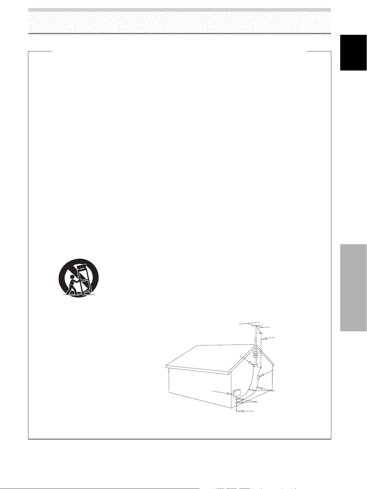
OUTDOOR ANTENNA GROUNDING — If an
outside antenna or cable system is connected to
the product, be sure the antenna or cable
system is grounded so as to provide some
protection against voltage surges and built-up
static charges. Article 810 of the National
Electrical Code, ANSI/NFPA 70, provides
information with regard to proper grounding of
the mast and supporting structure, grounding of
the lead-in wire to an antenna discharge unit,
size of grounding conductors, location of
antenna-discharge unit, connection to
grounding electrodes, and requirements for the
grounding electrode. See Figure A.
LIGHTNING — For added protection for this
product during a lightning storm, or when it is
left unattended and unused for long periods of
time, unplug it from the wall outlet and
disconnect the antenna or cable system. This
will prevent damage to the product due to
lightning and power-line surges.
POWER LINES — An outside antenna system
should not be located in the vicinity of overhead
power lines or other electric light or power
circuits, or where it can fall into such power
lines or circuits. When installing an outside
antenna system, extreme care should be taken
to keep from touching such power lines or
circuits as contact with them might be fatal.
OVERLOADING — Do not overload wall outlets,
extension cords, or integral convenience
receptacles as this can result in a risk of fire or
electric shock.
ELECTRIC
SERVICE
EQUIPMENT
Fig. A
OBJECT AND LIQUID ENTRY — Never push
objects of any kind into this product through
openings as they may touch dangerous voltage
points or short-out parts that could result in a
fire or electric shock. Never spill liquid of any
kind on the product.
SERVICING — Do not attempt to service this
product yourself as opening or removing covers
may expose you to dangerous voltage or other
hazards. Refer all servicing to qualified service
personnel.
DAMAGE REQUIRING SERVICE — Unplug this
product from the wall outlet and refer servicing
to qualified service personnel under the
following conditions:
• When the power-supply cord or plug is
damaged.
• If liquid has been spilled, or objects have fallen
into the product.
• If the product has been exposed to rain or water.
• If the product does not operate normally by
following the operating instructions. Adjust only
those controls that are covered by the operating
instructions as an improper adjustment of other
controls may result in damage and will often
require extensive work by a qualified technician
to restore the product to its normal operation.
• If the product has been dropped or damaged in
any way.
• When the product exhibits a distinct change in
performance — this indicates a need for service.
REPLACEMENT PARTS — When replacement parts
are required, be sure the service technician has
used replacement parts specified by the
manufacturer or have the same characteristics
as the original part. Unauthorized substitutions
may result in fire, electric shock, or other
hazards.
SAFETY CHECK — Upon completion of any service
or repairs to this product, ask the service
technician to perform safety checks to
determine that the product is in proper
operating condition.
WALL OR CEILING MOUNTING — The product
should not be mounted to a wall or ceiling.
HEAT — The product should be situated away from
heat sources such as radiators, heat registers,
stoves, or other products (including amplifiers)
that produce heat.
ANTENNA
LEAD IN
WIRE
GROUND
CLAMP
ANTENNA
DISCHARGE UNIT
(NEC SECTION 810-20)
GROUNDING CONDUCTORS
(NEC SECTION 810-21)
GROUND CLAMPS
POWER SERVICE GROUNDING
ELECTRODE SYSTEM
(NEC ART 250, PART H)
NEC — NATIONAL ELECTRICAL CODE
English
Safety Precautions
D1-4-2-2_En
iii
ii
EN
Page 4
English
Safety Precautions
FEDERAL COMMUNICATIONS COMMISSION
DECLARATION OF CONFORMITY
This device complies with part 15 of the FCC Rules. Operation is subject to the following
two conditions: (1) This device may not cause harmful interference, and (2) this device
must accept any interference received, including interference that may cause undesired
operation.
Product Name: Plasma Display
Model Number: PDP-5004 / PDP-5014 / PDP-4304 / PDP-4314
Product Category: Class B Personal Computers & Peripherals
Responsible Party Name: PIONEER ELECTRONICS [USA] INC. Customer Support Division
Address: P.O. BOX 1760, LONG BEACH, CA., 90801-1760 U.S.A.
Phone: (800)421-1625
URL http://www.pioneerelectronics.com
Should this product require service in the U.S.A. and you wish to locate the nearest Pioneer
Authorized Independent Service Company, or if you wish to purchase replacement parts,
operating instructions, service manuals, or accessories, please call the number shown
below.
Safety Precautions
8 0 0 – 4 2 1 – 1 4 0 4
Please do not ship your product to Pioneer without first calling the Customer Support
Division at the above listed number for assistance.
Pioneer Electronics (USA) Inc.
Customer Support Division
P. O. BOX 1760, Long Beach,
CA 90801-1760, U.S.A.
For warranty information please see the Limited Warranty sheet included with your product.
Should this product require service in Canada, please contact a Pioneer Canadian
Authorized Dealer to locate the nearest Pioneer Authorized Service Company in Canada.
Alternatively, please contact the Customer Satisfaction Department at the following address:
Pioneer Electronics of Canada, Inc.
Customer Satisfaction Department
300 Allstate Parkway, Markham, Ontario L3R OP2
1(877)283-5901
For warranty information please see the Limited Warranty sheet included with your product.
Si ce produit doit être réparé au Canada, veuillez vous adresser à un distributeur autorisé
Pioneer du Canada pour obtenir le nom du Centre de Service Autorisé Pioneer le plus près
de chez-vous. Vous pouvez aussi contacter le Service à la clientèle de Pioneer:
Pioneer Électroniques du Canada, Inc.
Service à la clientèle
300, Allstate Parkway, Markham, Ontario L3R OP2
1(877)283-5901
iv
iii
EN
Pour obtenir des renseignements sur la garantie, veuillez vous reporter au feuillet sur la
garantie restreinte qui accompagne le produit.
S018_A_EF
Page 5

Notes on Installation Work:
This product is marketed assuming that it is installed by qualified
personnel with enough skill and competence. Always have an
installation specialist or your dealer install and set up the product.
PIONEER cannot assume liabilities for damage caused by
mistake in installation or mounting, misuse, modification or a
natural disaster.
Note for Dealers:
After installation, be sure to deliver this manual to the customer
and explain to the customer how to handle the product.
Contents
Thank you very much for purchasing this PIONEER
product.
Before using your Plasma Display, please read the
“Safety Precautions” and these “Operating Instructions”
carefully so you will know how to operate the Plasma
Display properly. Keep this manual in a safe place. You
will find it useful in the future.
English
Safety Precautions ................................. i
Before Proceeding ................................. 2
How to Use This Manual ......................................... 2
Checking Supplied Accessories.............................. 4
Part Names and Functions ................... 5
Main Unit .................................................................. 5
Remote Control Unit................................................ 6
Connection Panel ..................................................... 9
Installation and Connections ..............11
Installation of the Unit ........................................... 11
About the Input Connectors on this Unit ............. 12
Connection to INPUT1 and INPUT5 ..................... 12
Connection to INPUT2 ........................................... 15
Connection to INPUT3 ........................................... 15
Connection to INPUT4 ........................................... 15
About DTV Set Top Box Connection .................... 16
Audio connections ................................................. 17
Power Cord Connection ........................................ 18
How to Route Cables ............................................. 19
System Settings .................................. 20
Setting the Onscreen Display Language ............. 20
Settings After Connections (INPUT1, 2, 5)........... 21
Picture and Screen Adjustment ......... 31
Picture Adjustment ................................................31
Returning to the Original Picture
Adjustment Values................................................. 32
Adjusting Screen POSITION, CLOCK,
and PHASE (Automatic Adjust) ............................ 33
Adjusting Screen POSITION, CLOCK,
and PHASE (Manual Adjust) .................................33
Other Operations ................................ 36
Setting the PURECINEMA Mode .......................... 36
Energy Saving Settings (ENERGY SAVE) ............ 37
Automatic Power-off
(POWER MANAGEMENT) .....................................38
Setting the Orbiter (ORBITER) .............................. 39
Side Mask Position (MASK CONTROL)................ 40
Additional Information........................ 42
Cleaning.................................................................. 42
Troubleshooting ..................................................... 42
Precautions Regarding Use .................................. 44
STANDBY and ON Indicators ................................ 44
Specifications ......................................................... 45
Appendix 1 ............................................................. 46
Appendix 2 ............................................................. 47
Appendix 3 ............................................................. 49
Explanation of Terms ............................................. 49
Contents
Operation ............................................. 25
Selecting Input Source .......................................... 25
Adjusting Sound Volume ...................................... 26
Muting the Sound .................................................. 26
Confirming Current Status .................................... 26
Changing Screen Size ........................................... 27
Multiscreen Display ............................................... 28
Setting AV SELECTION.......................................... 30
1
EN
Page 6
Before Proceeding
How to Use This Manual
English
This manual is set up to follow the course of actions and
operations in the order that would seem most logical for
someone setting up this unit.
Once the unit has been taken out of the box and it has
been confirmed that all the parts have been received
(page 4), it may be beneficial to look over the section
“Part Names and Functions” starting on page 5 to
become acquainted with the plasma monitor and remote
control unit, as their respective buttons and controls will
be referred to throughout this manual.
The section “Installation and Connections” starting on
page 11 covers all the necessary points regarding
installation of the plasma display and connections to a
wide variety of components.
The section “System Settings” starting on page 20
covers the on-screen settings necessary for correct
operation of the plasma display with its connected
components. Depending on the connections made, this
section may or may not be necessary.
The remainder of the sections in this manual is dedicated
to the basic operations associated with selecting a source
component up to the more complex operations
associated with adjusting the plasma display picture to
match the requirements of specific components and
personal preferences.
Before Proceeding
Apple and Macintosh are registered trademarks of Apple Computer, Inc.
Microsoft is a registered trademark of Microsoft Corporation.
NEC and PC-9800 are trademarks of NEC Corporation.
VESA and DDC are registered trademarks of Video Electronics Standards Association.
Power Management and Sun Microsystems are registered trademarks of Sun Microsystems, Inc.
VGA and XGA are registered trademarks of International Business Machines Co., Inc.
HDMI, the HDMI logo and High-Definition Multimedia Interface are trademarks or registered
trademarks of HDMI Licensing LLC.
TMDS is registered trademark of Silicon Image Inc.
This product includes FontAvenue® fonts licensed by NEC Corporation. FontAvenue is a registered
trademark of NEC Corporation.
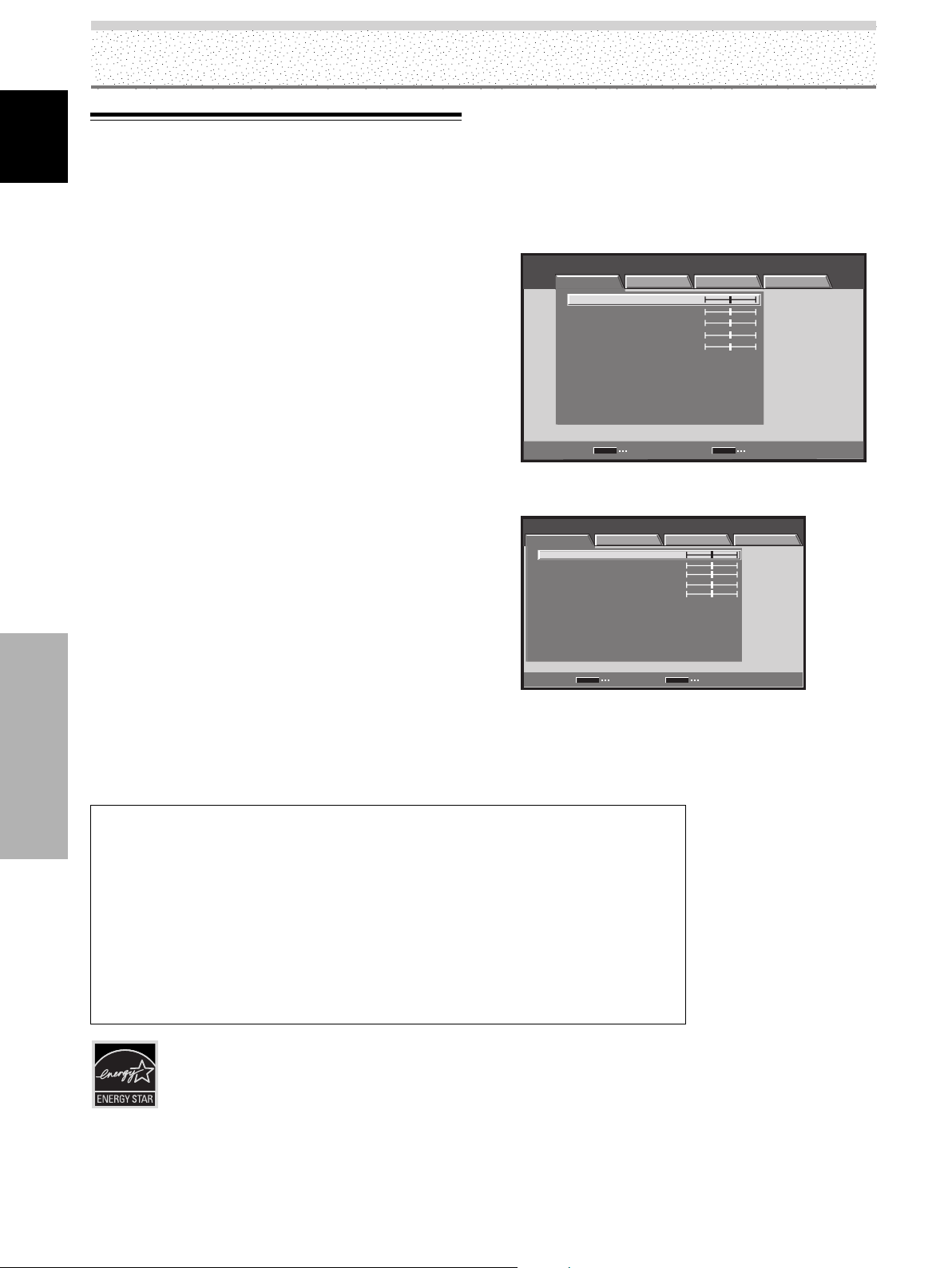
Regarding menu displays
The example menu displays provided in this manual are
those for the PDP-5004/PDP-5014 models. The PDP-4304/
PDP-4314 displays differ as shown:
Example of PDP-5004/PDP-5014 Menu Display:
STANDARD INPUT1
PICTURE SCREEN SETUP OPTION
CONTRAST
BRIGHTNESS
COLOR
TINT
SHARPNESS
MPEG NR
DNR
CTI
COLOR TEMP. MID
PICTURE RESET
SET
ENTER
Example of PDP-4304/PDP-4314 Menu Display:
STANDARD INPUT1
PICTURE SCREEN SETUP OPTION
CONTRAST
BRIGHTNESS
COLOR
TINT
SHARPNESS
MPEG NR
ONR
CTI
COLOR TEMP.
PICTURE RESET
SET
ENTER EXIT
Please note that the actual contents displayed are the
same for both the PDP-5004/PDP-5014 and PDP-4304 /
PDP-4314.
:
0
:
0
:
0
:
0
:
0
:
ON
:
MID
:
ON
:
MENU
EXIT
:
0
:
0
:
0
:
0
:
0
:
ON
:
MID
:
ON
:
MID
MENU
For U.S. Model
2
EN
Page 7
About operations in this manual
Each operation is described in its proper operating order.
These Operating Instructions will refer to the operating
controls found on the remote control unit, with the
exception of those buttons found only on the main
plasma display itself. When the plasma display controls
include equivalent buttons to those found on the remote
control unit, the commands can be performed on the
main unit as well.
Before Proceeding
English
The following illustrations are an example of the actual
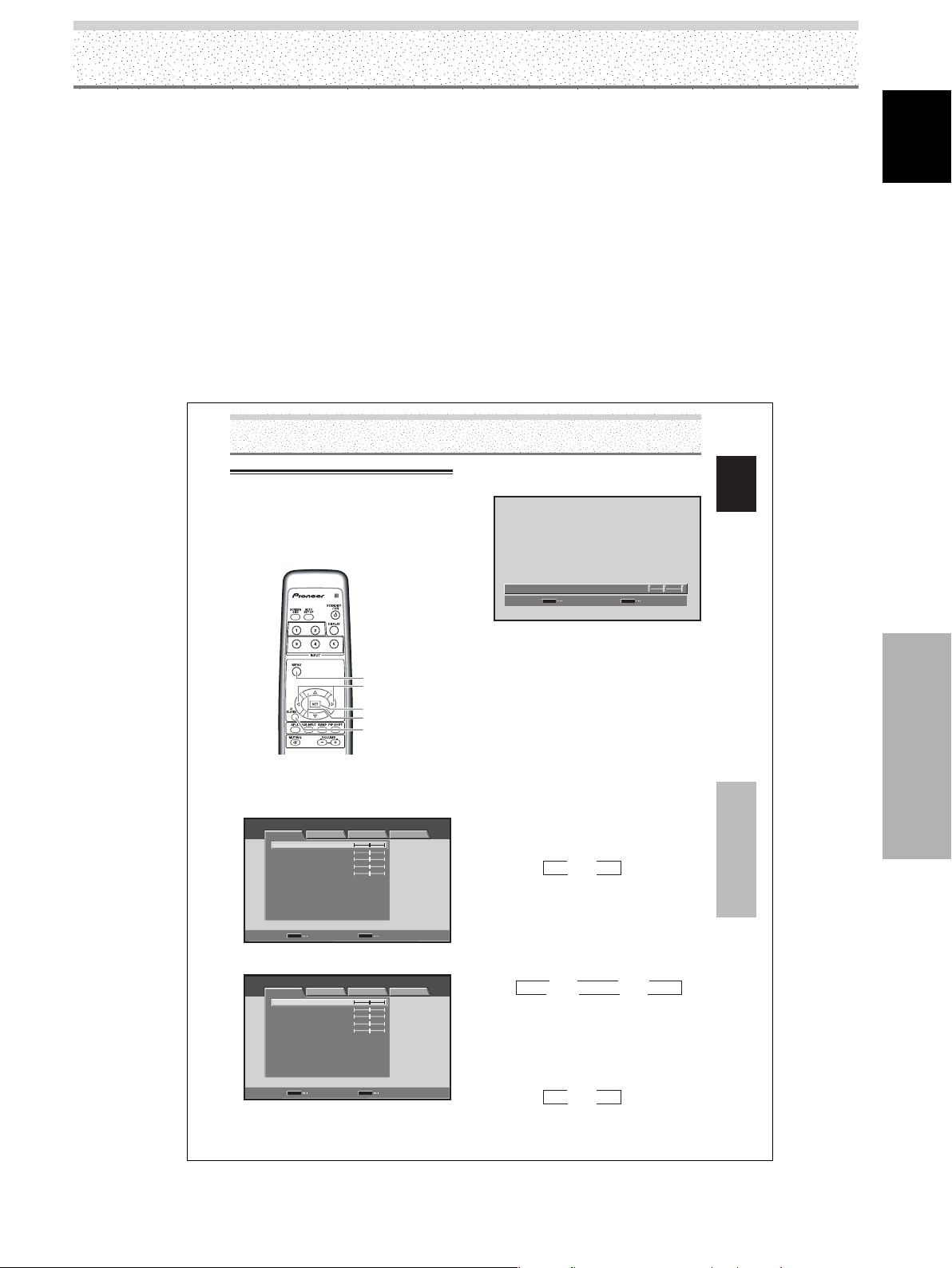
operations used for the section “PICTURE adjustment”.
The examples are provided to allow you to confirm
whether the operation is performed correctly or not.
Picture and Screen Adjustment
Picture Adjustment
You can save picture adjustment setting values for each
INPUT and each AV SELECTION mode.
Note
This setting is not possible when in the DYNAMIC mode in [AV
SELECTION].
MENU
2/3
SET
5/∞
AV
SELECTION
Remote control unit
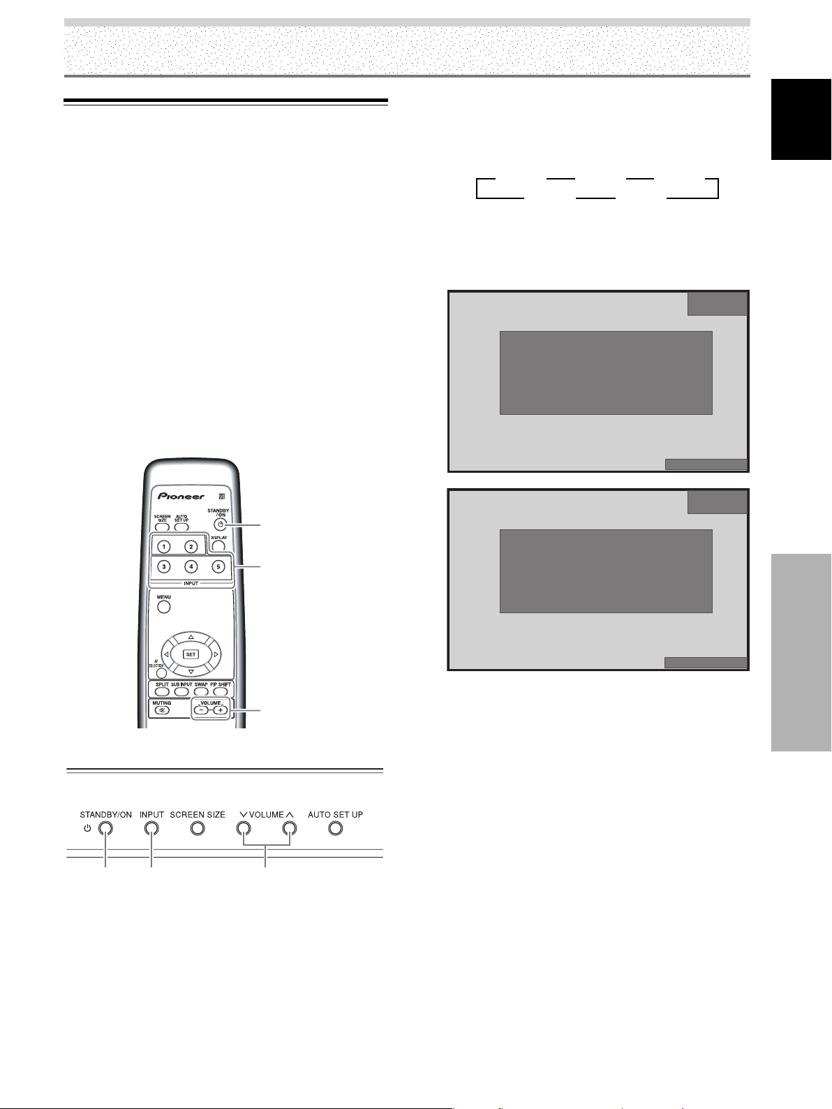
1 Press the AV SELECTION button to select the
desired mode (Refer to page 30).
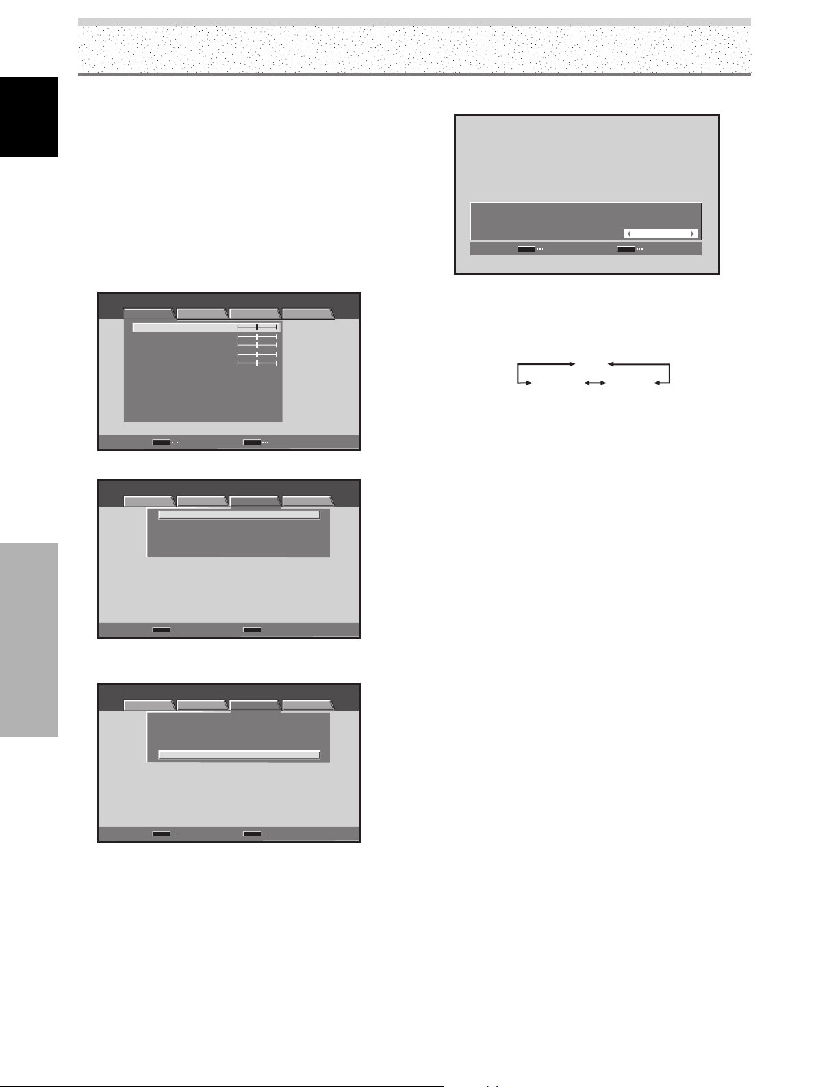
2 Press the MENU button to display the menu.
STANDARD INPUT1
PICTURE SCREEN SETUP OPTION
CONTRAST
BRIGHTNESS
COLOR
TINT
SHARPNESS
MPEG NR
DNR
CTI
COLOR TEMP. MID
PICTURE RESET
SET
3 Use the 5/∞ buttons to select the item, then press
the SET button.
STANDARD INPUT1
PICTURE SCREEN SETUP OPTION
CONTRAST
BRIGHTNESS
COLOR
TINT
SHARPNESS
MPEG NR
DNR
CTI
COLOR TEMP. MID
PICTURE RESET
SET
ENTER
ENTER
:
0
:
0
:
0
:
0
:
0
:
ON
:
MID
:
ON
:
MENU
EXIT
:
0
:
0
:
0
:
0
:
0
:
ON
:
MID
:
ON
:
MENU
EXIT
Note
The screen images depicted in these Operating Instructions
should be considered typical images; some difference will be
seen in practice, depending on the screen item displayed and its
contents, the input source and various other control settings.
4 Use the 2/3 buttons to adjust picture quality to
the desired setting.
:
:
0CONTRAST
SR+MODE
SET
SET
5 Press the SET button.
Adjustment values are saved, and you return to the
display shown in step 3.
6 After completing settings, press the MENU button
to return to the normal display.
¶ Adjustment and setting items during video signal
input
CONTRAST ...
BRIGHTNESS ...
COLOR ........
TINT .............
SHARPNESS ...
MPEG NR
Use when there is mosquito noise in the picture when
viewing a digital broadcast, playing a DVD etc.
Each time you press the 2/3 buttons, the setting
changes as follows:
¶ As you change from OFF 3 ON, the effect becomes
DNR
This function reduced graininess to provide a clearer
picture.
Each time you press the 2/3 buttons, the setting
changes as follows:
¶ As you change from LOW 3 MID 3 HIGH, the effect
CTI
This lets you brighten color contour as desired.
Each time you press the 2/3 buttons, the setting
changes as follows:
¶ ON
¶ OFF …CTI is not operating.
Decrease
Contrast becomes weaker Contrast becomes stronger
Picture becomes darker Picture becomes brighter
Colors become weaker Colors become stronger
Skin tones become purplish Skin tones become greenish
Picture becomes softer Picture becomes sharper
3 OFF 2
3 ON 2
stronger.
3 OFF 2 3 LOW 2
3 HIGH 2
becomes stronger.
3 OFF 2
….
CTI is operating.
3 ON 2
MENU
Increase
3 MID 2
ON
EXIT
English
Picture and Screen Adjustment
31
EN
Before Proceeding
3
EN
Page 8
Before Proceeding
Checking Supplied Accessories
English
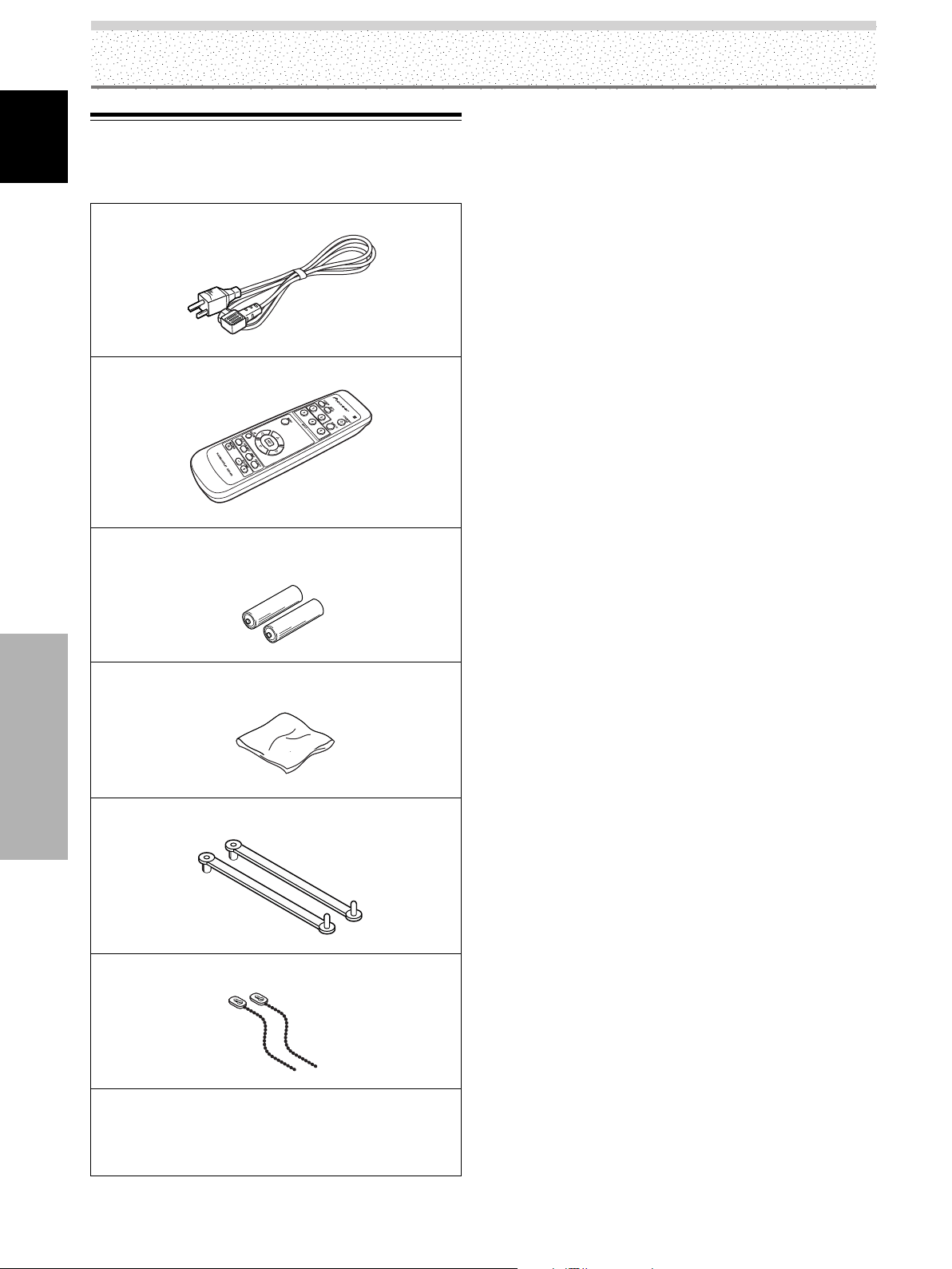
Check that the following accessories were supplied.
1 Power cord
2 Remote control unit
Illustration depicts PDP-5004
and PDP-4304 models.
3 AA (R6) batteries (x 2)
4 Cleaning cloth (for wiping front panel)
Before Proceeding
5 Speed clamps (x 2)
6 Bead bands (x 2)
÷ Operating Instructions
÷ Warranty
4
EN
Page 9
Part Names and Functions
5 6 7 98
Main Unit
Main unit
English
PDP-4304
4
4
PDP-5004
1
Operation panel on the main unit
23
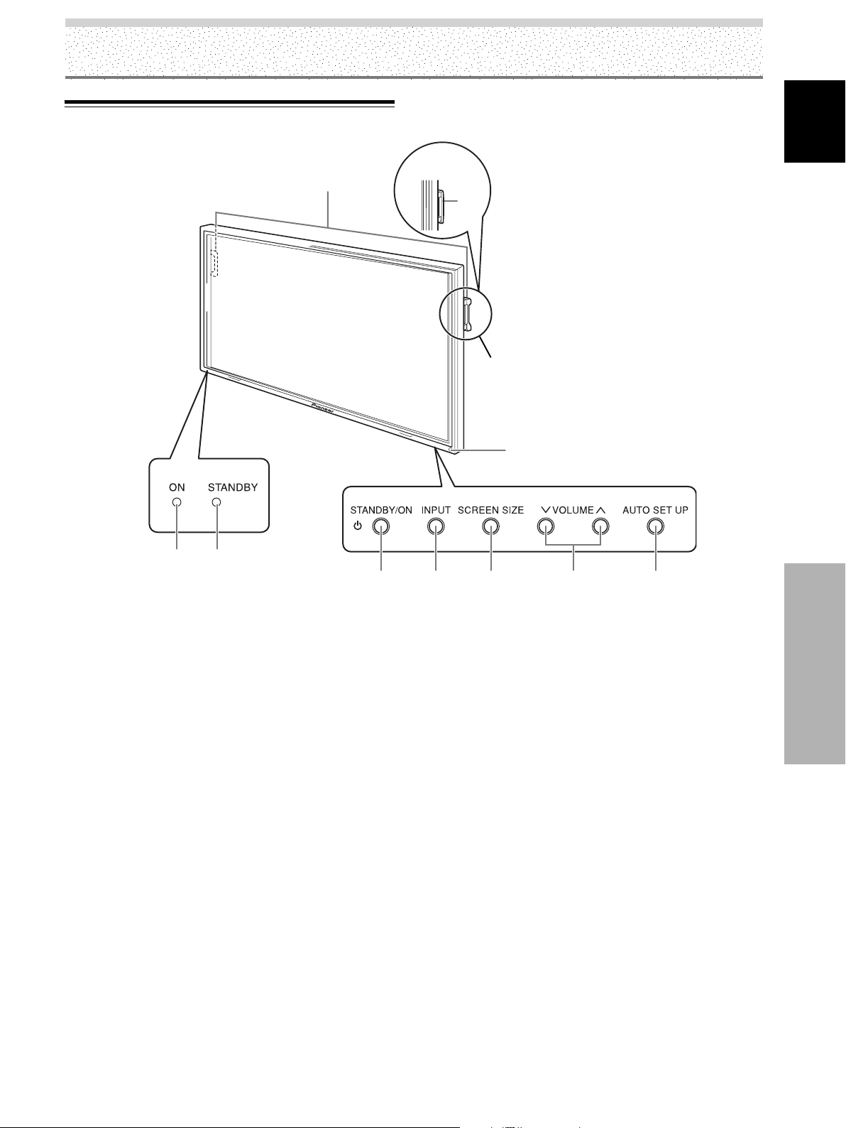
Main unit
1 Remote control sensor
Point the remote control toward the remote sensor to
operate the unit (page 8).
2 ON indicator
Lights green when the plasma display is operating
(page 25).
When flashing, the indicator is used to indicate error
messages (page 44).
3 STANDBY indicator
Lights red when the unit is in standby mode (page 25).
When flashing, the indicator is used to indicate error
messages (page 44).
4 Handles
The plasma displays PDP-5004 and PDP-4304 utilize
differing methods of handle attachment, but the
handles themselves are used in the same way.
Operation panel on the main unit
5 STANDBY/ON button
Press to put the display in operation or standby mode
(page 25).
6 INPUT button
Press to select the input (page 25).
7 SCREEN SIZE button
Press to select the screen size (page 27).
8 VOLUME (+/–) buttons
When not indicated for use in onscreen menu items,
these buttons are used for adjusting the sound
volume (pages 25 and 26).
9 AUTO SET UP button
When using computer signal input, automatically sets
the [POSITION], [CLOCK] and [PHASE] to optimum
values (page 33).
Part Names and Functions
5
EN
Page 10
Part Names and Functions
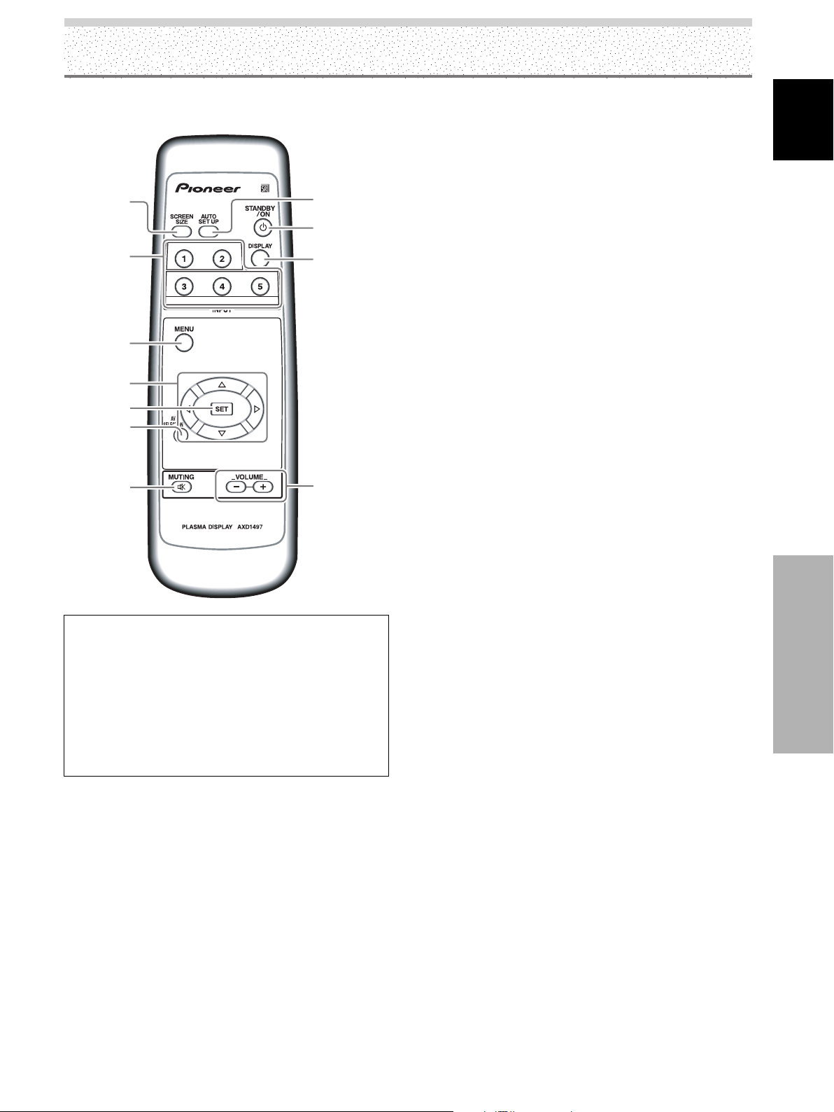
Remote Control Unit
English
[PDP-5004, PDP-4304]
1
2
0
-
=
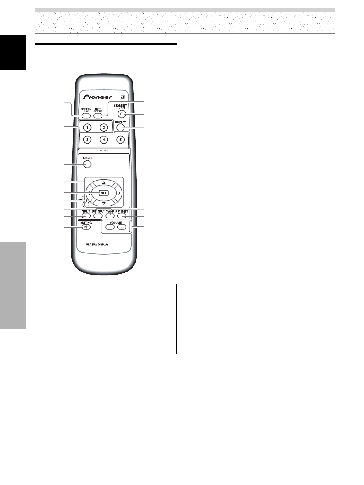
1 SCREEN SIZE button
Press to select the screen size (pages 27 to 28).
2 INPUT buttons
Press to select the input (page 25).
3 MENU button
Press to open and close the on-screen menu
(pages 20 to 41).
4 ADJUST (5/∞/3/2) buttons
Use to navigate menu screens and to adjust various
settings on the unit (pages 20 to 41).
5 SET button
Press to adjust or enter various settings on the unit
(pages 20 to 41).
3
4
5
6
8
9
When handling the remote control unit
¶ Do not drop the remote control unit or expose it to
moisture.
Part Names and Functions
¶ Do not use the remote control unit in a location subject to
direct sunlight, heat radiation from a heater, or in a place
subject to excessive humidity.
¶ When the remote control unit’s batteries begin to wear out,
the operable distance will gradually become shorter. When
this occurs, replace all batteries with new ones as soon as
possible.
AXD1496
~7
!
@
6 AV SELECTION button
Press to switch to Picture settings.
(VIDEO mode: DYNAMIC, STANDARD, MOVIE,
GAME, USER
PC mode: STANDARD, USER)
7 SUB INPUT button
During multi-screen display, use this button to change
inputs to subscreens (page 28).
8 SPLIT button
Press to switch to multi-screen display (page 28).
9 MUTING button
Press to mute the volume (page 26).
0 AUTO SET UP button
When using computer signal input, automatically sets
the [POSITION], [CLOCK] and [PHASE] to optimum
values (page 33).
- STANDBY/ON button
Press to put the unit in operation or standby mode
(page 25).
= DISPLAY button
Press to view the unit’s current input and setup mode
(page 26).
6
EN
~ SWAP button
During multi-screen display, use this button to switch
between main screen and subscreen (page 28).
! PIP SHIFT button
When using PinP mode with multi-screen display, use
this button to move the position of subscreen (page
28).
@ VOLUME (+/–) buttons
Use to adjust the volume (pages 25 and 26).
Page 11
Part Names and Functions
[PDP-5014, PDP-4314]
1
2
3
4
5
6
7
8
9
0
-
1 SCREEN SIZE button
Press to select the screen size (pages 27 to 28).
English
2 INPUT buttons
Press to select the input (page 25).
3 MENU button
Press to open and close the on-screen menu
(pages 20 to 41).
4 ADJUST (5/∞/3/2) buttons
Use to navigate menu screens and to adjust various
settings on the unit (pages 20 to 41).
5 SET button
Press to adjust or enter various settings on the unit
(pages 20 to 41).
6 AV SELECTION button
Press to switch to Picture settings.
(VIDEO mode: DYNAMIC, STANDARD, MOVIE,
GAME, USER
PC mode: STANDARD, USER)
7 MUTING button
Press to mute the volume (page 26).
When handling the remote control unit
¶ Do not drop the remote control unit or expose it to
moisture.
¶ Do not use the remote control unit in a location subject to
direct sunlight, heat radiation from a heater, or in a place
subject to excessive humidity.
¶ When the remote control unit’s batteries begin to wear out,
the operable distance will gradually become shorter. When
this occurs, replace all batteries with new ones as soon as
possible.
8 AUTO SET UP button
When using computer signal input, automatically sets
the [POSITION], [CLOCK] and [PHASE] to optimum
values (page 33).
9 STANDBY/ON button
Press to put the unit in operation or standby mode
(page 25).
0 DISPLAY button
Press to view the unit’s current input and setup mode
(page 26).
- VOLUME (+/–) buttons
Use to adjust the volume (pages 25 and 26).
Part Names and Functions
7
EN
Page 12
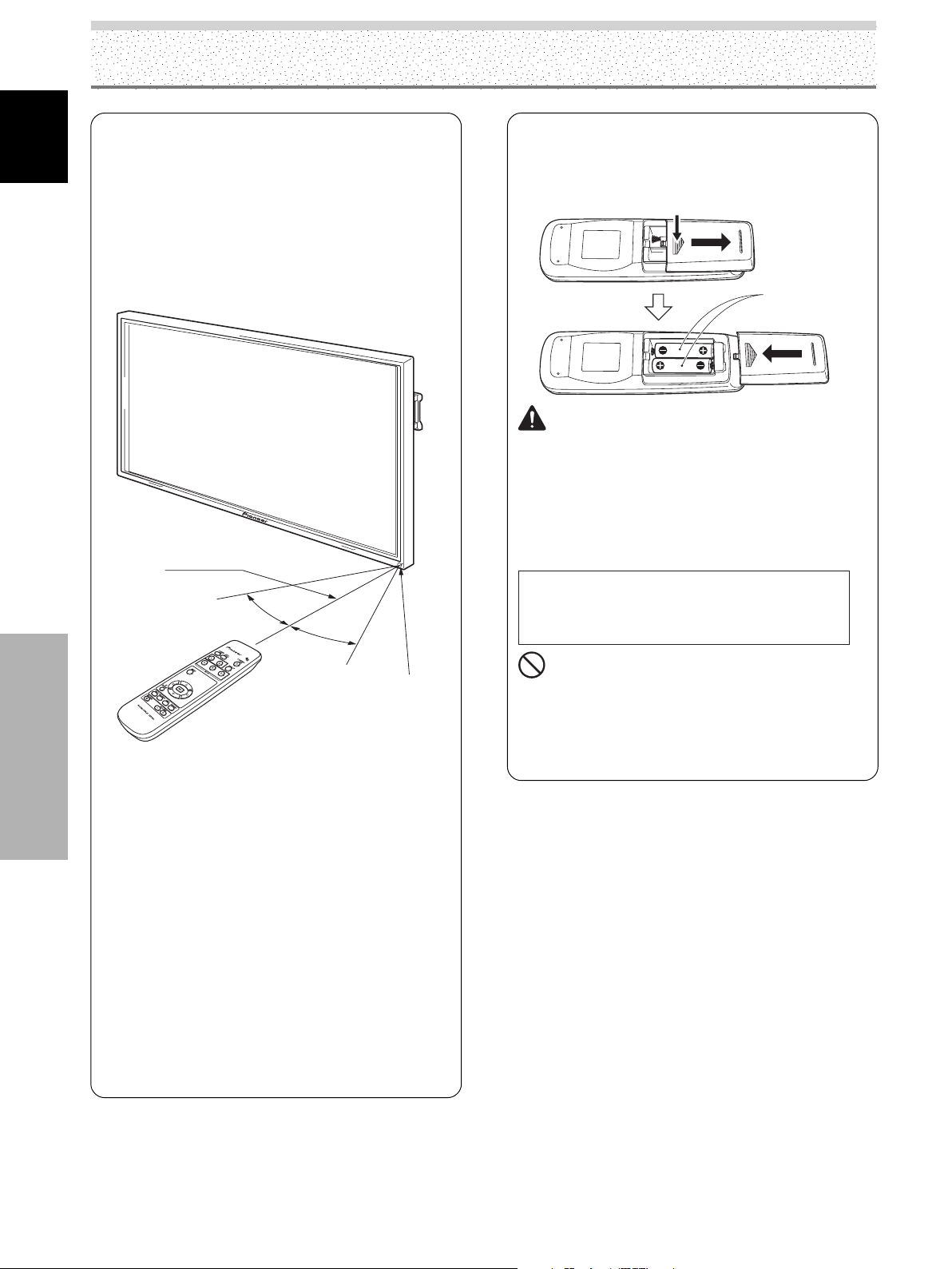
Part Names and Functions
Operating range of the remote
English
Part Names and Functions
control unit
When operating the remote control unit, point it at the
remote sensor (Î) located on the front panel of the
main unit. The remote control unit is operable up to 7 m
(23 feet) from the unit and within a 30° angle on each
side of the sensor.
7 m
(23 feet)
If you are having difficulty with operation of
the remote control unit
¶ The remote control unit may not operate if there are
objects placed between it and the display.
¶ Operational distance will gradually become shorter as the
batteries begin to wear out, replace weak batteries with
new ones as soon as possible.
¶ This unit discharges infrared rays from the screen. Placing a
video deck or other component that is operated by an
infrared remote control unit near this unit may hamper that
component’s reception of the remote control’s signal, or
prevent it from receiving the signal entirely. Should this
occur, move the component to a position further away from
this unit.
¶ Depending on the installation surroundings, this unit’s
remote control unit may be influenced by the infrared rays
discharged from the plasma display, hampering reception of
its rays or limiting its operational distance. The strength of
infrared rays discharged from the screen will differ
according to the picture displayed.
30°
30°
Remote Sensor
Illustration depicts PDP-5004
and PDP-4304 models.
Inserting the batteries in the
remote control unit
While pressing down lightly, slide
in the direction of the arrow.
Tw o AA (R6)
batteries
CAUTION
¶ Insert batteries so that the plus (+) and minus (–) sides
are aligned according to the markings in the battery case.
¶ When not using the remote control unit for a long period
of time (1 month or more), remove the batteries from the
remote control unit to prevent leaking of battery fluid. If
battery liquid has leaked, thoroughly wipe the inside of
the case until all liquid is removed, and then insert new
batteries.
When disposing of used batteries, please comply
with governmental regulations or
environmental public instruction’s rules that
apply in your country/area.
NO!
¶ Do not mix new batteries with used ones.
¶ The voltage of batteries may differ even if they are the
same shape. Please do not mix different kinds of
batteries together.
¶ Do not charge, short, disassemble or throw the provided
batteries in a fire.
D3-4-2-3-1_En
8
EN
Page 13
Part Names and Functions
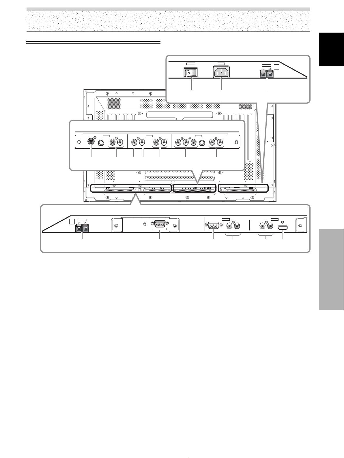
Connection Panel
Illustration depicts PDP-5004, PDP-5014, PDP-4304
and PDP-4314 models.
INPUT3 INPUT4 INPUT5
S-VIDEO
0 = ~- ! @ #
SPEAKER
8Ω ~16Ω
R
+ –
AUDIO AUDIO AUDIO
VIDEO
RL RL RLYCB/PBCR/P
IN OUT
SERVICE ONLY
COMPONENT
VIDEO
POWER
OFF ON
English
AC IN
SPEAKER
8Ω ~16Ω
+ –
L
987
R
ANALOG RGB IN
D-Sub
INPUT1
INPUT1
AUDIO
AUDIO
INPUT2
RLRL
HDMI
1
Plasma Display Section
The plasma display is provided with 5 video input
connectors, 1 video output connector, audio input jacks and
speaker terminals.
For instructions regarding connections, consult the pages
noted in parentheses by each item.
1 SPEAKER (R) terminal
For connection of an external right speaker.
Connect a speaker whose impedance is 8 –16 Ω.
2 RS-232 Terminal (used in the factory setup)
3 ANALOG RGB IN (INPUT1) (mini D-sub 15 pin)
For connecting components equipped with RGB
outputs jacks, such as a personal computer or external
RGB decoder; or components equipped with
component output jacks, such as a DVD recorder.
Make sure that the connection made corresponds to
the format of the signal output from the connected
component (pages 13 to 14).
4 AUDIO (INPUT1) (RCA pin jack)
Use to obtain sound when INPUT1 is selected.
Connect this jack to the audio output connector of the
device connected to INPUT1 to this unit (page 17).
Note
The left audio channel (L) jack is not compatible with
monaural input sources.
23456
5 AUDIO (INPUT2) (RCA Pin jacks)
Use to obtain sound when INPUT2 (analog audio) is
selected.
Connect these jacks to the audio output connectors of
components connected to INPUT2 (page 17).
Note
The left audio channel (L) jack is not compatible with
monaural input sources.
6 HDMI (INPUT2) (HDMI jack)
For connection of components that have a digital
video output terminal such as a digital set top box,
DVD player, etc. compatible with HDCP. Before
attempting to connect one of these devices, read its
operating instructions to make sure that it can be
connected (page 15).
(HDCP = High-bandwidth Digital Content Protection)
(HDMI = High Definition Multimedia Interface)
7 MAIN POWER switch
Use to switch the main power of the plasma display
on and off.
8 AC IN
A power cable is furnished with the plasma display;
connect one end of the power cable to this connector,
and the other end to a standard AC power source.
9
EN
Part Names and Functions
Page 14

Part Names and Functions
9 SPEAKER (L) terminal
English
For connection of an external left speaker. Connect a
speaker that has an impedance of 8 –16 Ω.
0 S-VIDEO (INPUT3) (S-video jack)
For connection of components that have an S-video
output jack such as a video deck, video camera, laser
disc player, or DVD recorder (page 15).
- AUDIO R/L (INPUT3) (RCA Pin jacks)
Use to obtain sound when INPUT3 is selected.
Connect these jacks to the audio output connectors
of components connected to INPUT3 to this unit
(page 18).
= VIDEO IN (INPUT4) (RCA Pin jack)
For connection of components that have a composite
video output jack such as a video deck, video camera,
laser disc player, or DVD recorder (page 15).
~ VIDEO OUT (INPUT4) (RCA Pin jack)
Use the VIDEO OUT (INPUT4) jack to output the video
signal to an external monitor or other component.
Note
The video signal will not be output from the VIDEO OUT
(INPUT4) jack when the main power of this display is off or in
standby mode (page 15).
! AUDIO R/L (INPUT4) (RCA Pin jacks)
Use to obtain sound when INPUT4 is selected.
Connect these jacks to the audio output connectors
of components connected to INPUT4 to this unit
(page 18).
@ COMPONENT VIDEO (INPUT5) (RCA Pin jacks)
For connection of components that have component
video output jacks such as a DVD recorder (page 13).
# AUDIO R/L (INPUT5) (RCA Pin jacks)
Use to obtain sound when INPUT5 is selected. Connect
these jacks to the audio output connectors of components
Part Names and Functions
connected to INPUT5 to this unit (page 18).
10
EN
Page 15
Installation and Connections
Installation of the Unit
Installation using the optional PIONEER stand or
installation bracket
÷ Please be sure to request installation or mounting of this unit
or the installation bracket by the dealer where purchased.
÷ When installing, be sure to use the bolts provided with the
stand or installation bracket.
÷ For details concerning installation, please refer to the
instruction manual provided with the stand or installation
bracket.
Installation using accessories other than the
PIONEER stand or installation bracket (sold
separately)
÷ When possible, please install using parts and accessories
manufactured by PIONEER. PIONEER will not be held
responsible for accident or damage caused by the use of parts
and accessories manufactured by other companies.
÷ For custom installation, please consult the dealer where the
unit was purchased.
Air vents (fan)
b hole b hole
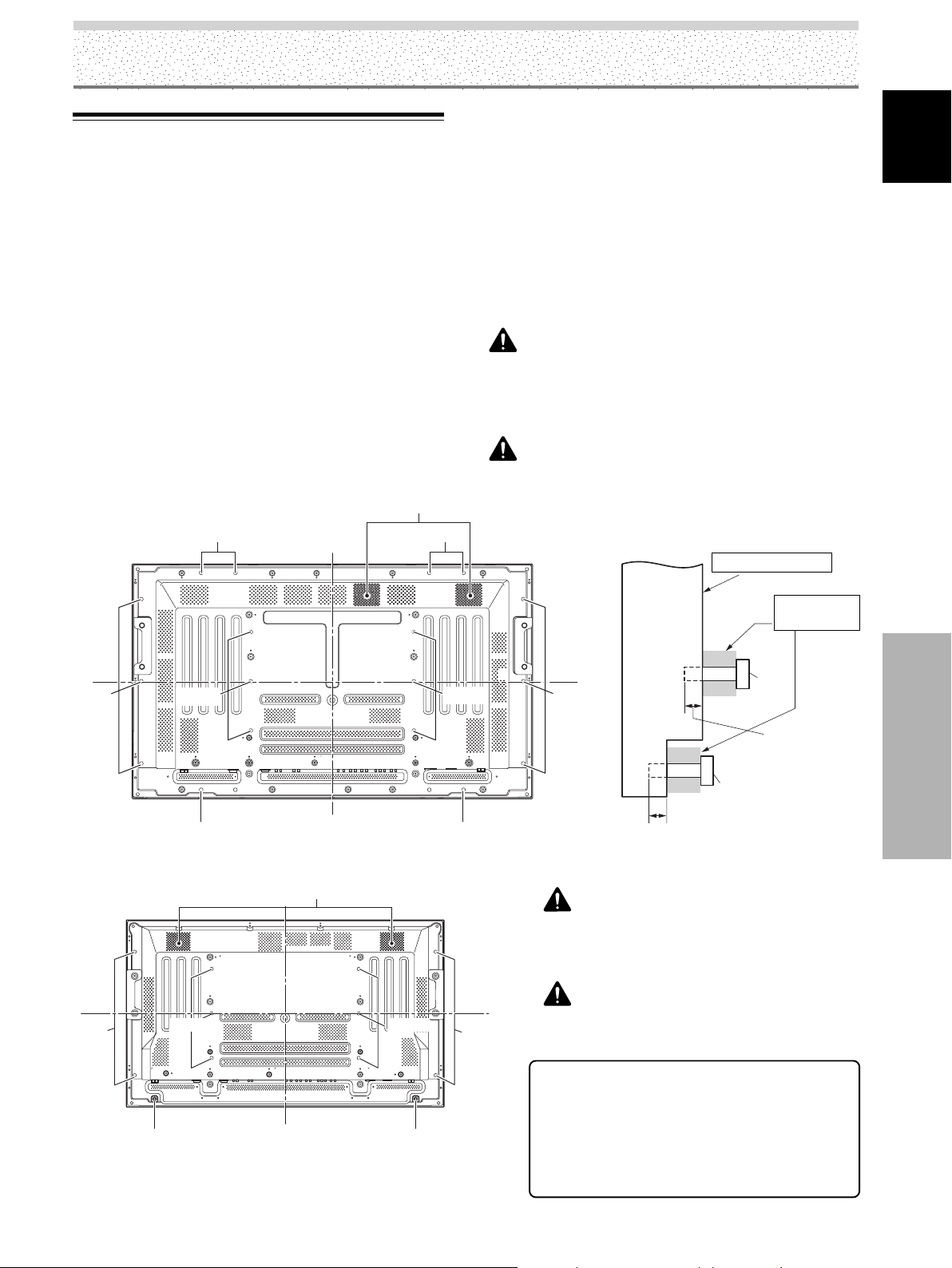
Wall-mount installation of the unit
This unit has been designed with bolt holes for wallmount installation, etc. The installation holes that can be
used are shown in the diagram below.
÷ Be sure to attach in 4 or more locations above and
below, left and right of the center line.
÷ Use bolts that are long enough to be inserted 1/2 inch
(12 mm) to 11/16 inch (18 mm) into the main unit from
the attaching surface for both a holes.
Refer to the side view diagram below.
÷ As this unit is constructed with glass, be sure to install
it on a flat, unwarped surface.
CAUTION
To avoid malfunction, overheating of this unit, and possible fire
hazard, make sure that the vents on the main unit are not
blocked when installing. Also, as hot air is expelled from the air
vents, be careful of deterioration and dirt build up on rear surface
wall, etc..
CAUTION
Please be sure to use an M8 (Pitch = 1.25 mm) bolt (Only
this size bolt can be used).
Attaching surface
English
b hole
Main unit
Center line
a hole
b hole b hole
Center line
a hole
b holeb hole
12 mm to 18 mm (1/2 in. to 11/16 in.)
Rear view diagram (PDP-5004/PDP-5014) Side view diagram
Air vents (fan)
CAUTION
This display unit weighs at least 67 lbs (30 kg) and has little
front-to-back depth, making it very unstable when stood on
edge. As a result, two or more persons should cooperate
when unpacking, moving, or installing the display.
a hole a hole
b hole b hole
Center line
Rear view diagram (PDP-4304/PDP-4314)
Center line
b hole
CAUTION
This unit incorporates a thin design. To ensure safety if
vibrated or shaken, please be sure to take measures to
prevent the unit from tipping over.
7 Optional line (sold separately)
(For details, please consult the dealer where this
unit was purchased.)
1 Table top stand : PDP-5004 / PDP-5014 /
PDP-4304 / PDP-4314
display stand.
2 Wall installation unit : Wall installation bracket
designed as a wall interface
for securing the unit.
Installation
bracket, etc..
a hole
Bolt
12 mm to 18 mm
(1/2 in. to 11/16 in.)
Bolt
b hole
Installation and Connections
11
EN
Page 16
Installation and Connections
CAUTION
÷ Handles should not be removed or reattached by anyone other
English
than the professional installation technician or service
personnel.
÷ If handles must be removed due to specific installation
conditions, the mounting screws should be stored carefully
together with the handles. To ensure safety, the mounting
screws should be tightened to a minimum torque of 2N·m (20
kgf·cm) when reattaching the handles.
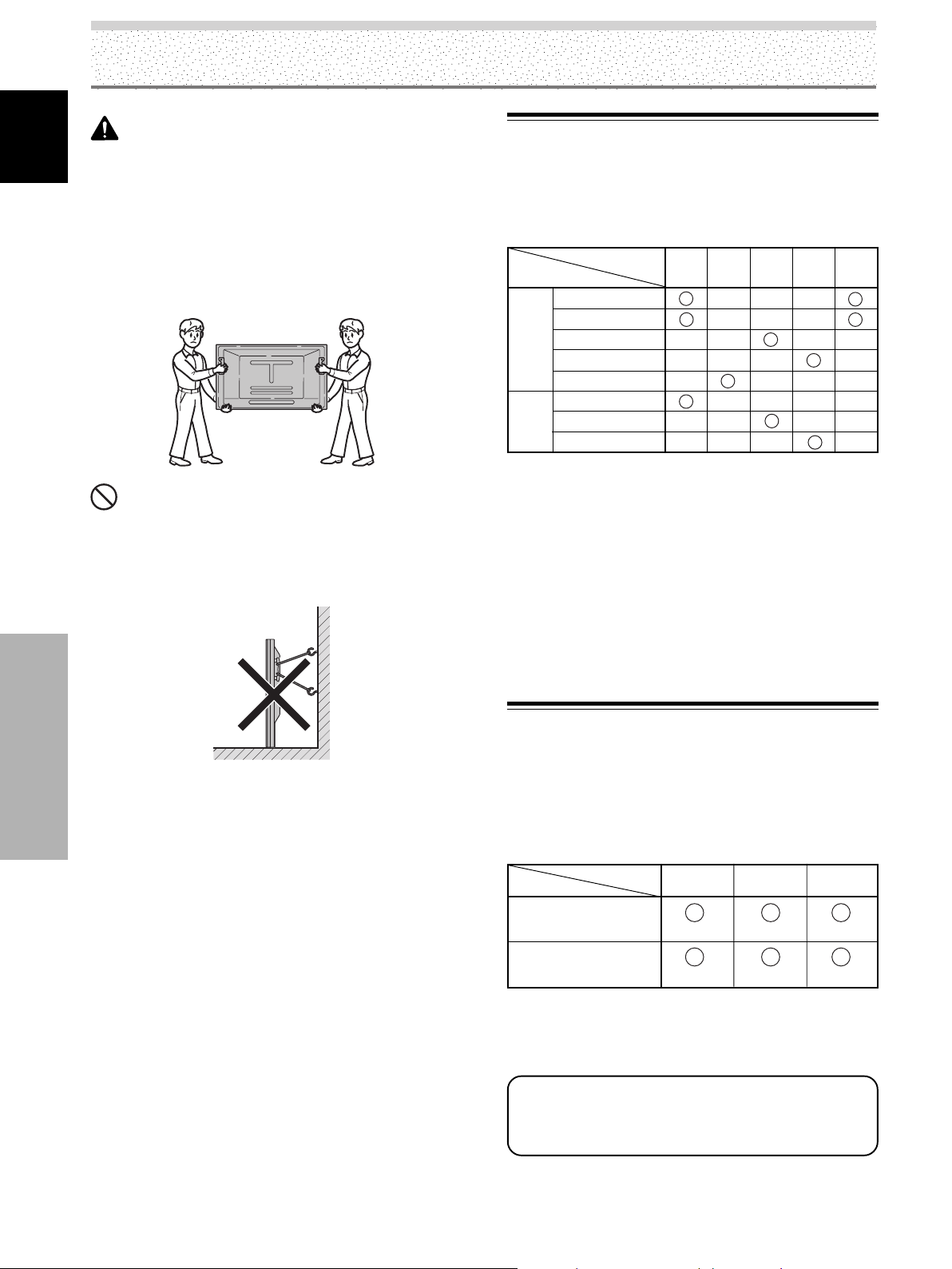
÷ When moving the display, it should always be carried by two
persons holding the rear handles in the manner shown.
NO!
÷ Never attempt to move the plasma display by holding only one
of the handles.
÷ When installing the plasma display, do not use the handles as
means of hanging the display; also do not use them as devices
to prevent tipping over (see illustration).
About the Input Connectors on this
Unit
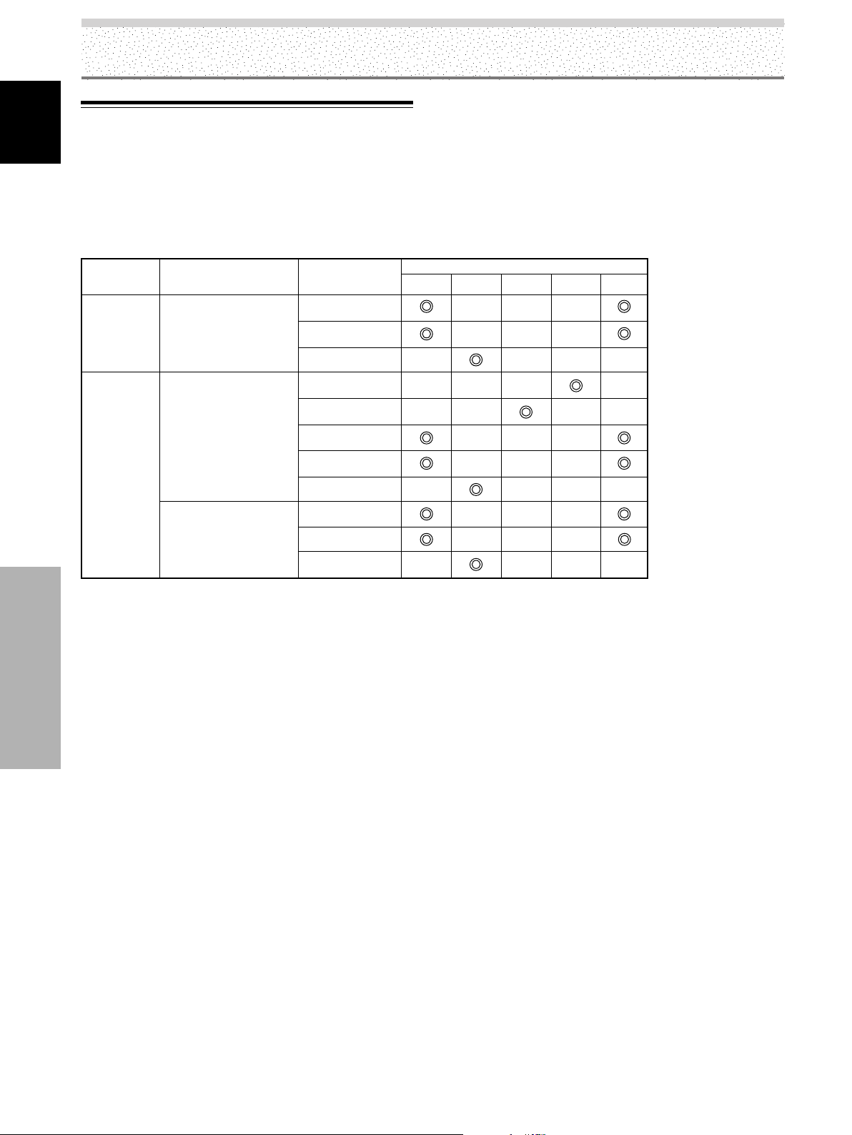
Consult the following chart when making connections to
a plasma display (pages 13 to 19).
Connected
component and signals
AV
component
Personal
computer
*1 Although INPUT1/INPUT5 are compatible with various kinds
of signals, setup using the on-screen menu is necessary after
connections are made in order match the characteristics of
the source component (pages 21 to 23).
*2 INPUT1 is compatible with Microsoft’s Plug & Play (VESA
DDC 1/2B).
*3 Depending on the video output board of the computer, this
type of connection may not be possible.
*4 Although INPUT2 is compatible with various kinds of signals,
setup using the on-screen menu is necessary after
connections are made in order match the characteristics of
the source component (pages 23 to 24).
Input Connector
Analog RGB
Component video
S-video
Composite video
Digital video
Analog RGB
S-video
(PC)
Composite video
INPUT
*1
1
*2
INPUT
*4
2
INPUT
3
*3
INPUT
4
*3
INPUT
*1
5
Installation and Connections
Connection to INPUT1 and INPUT5
Various components can be connected to the INPUT1 and
INPUT5 jacks. After connections are made, on-screen
setup is necessary to match the characteristics of the
connected component. Please see pages 21 to 23 for onscreen setup after connection.
Output source
INPUT5 terminal
Video component with
RGB output
Video component with
component video output
Note
When making connections to INPUT1, please refer to appendix 3
on page 49.
For the screen sizes and input signals that INPUT1
and INPUT5 are compatible with, please refer
to appendix 1 (page 46) and appendix 2 (pages 47
to 48).
[ON SYNC]
Y
G ON SYNC
YCB/PB CR/PR
CB/PB CR/PR
B
R
12
EN
Page 17
Installation and Connections
Connection to AV components
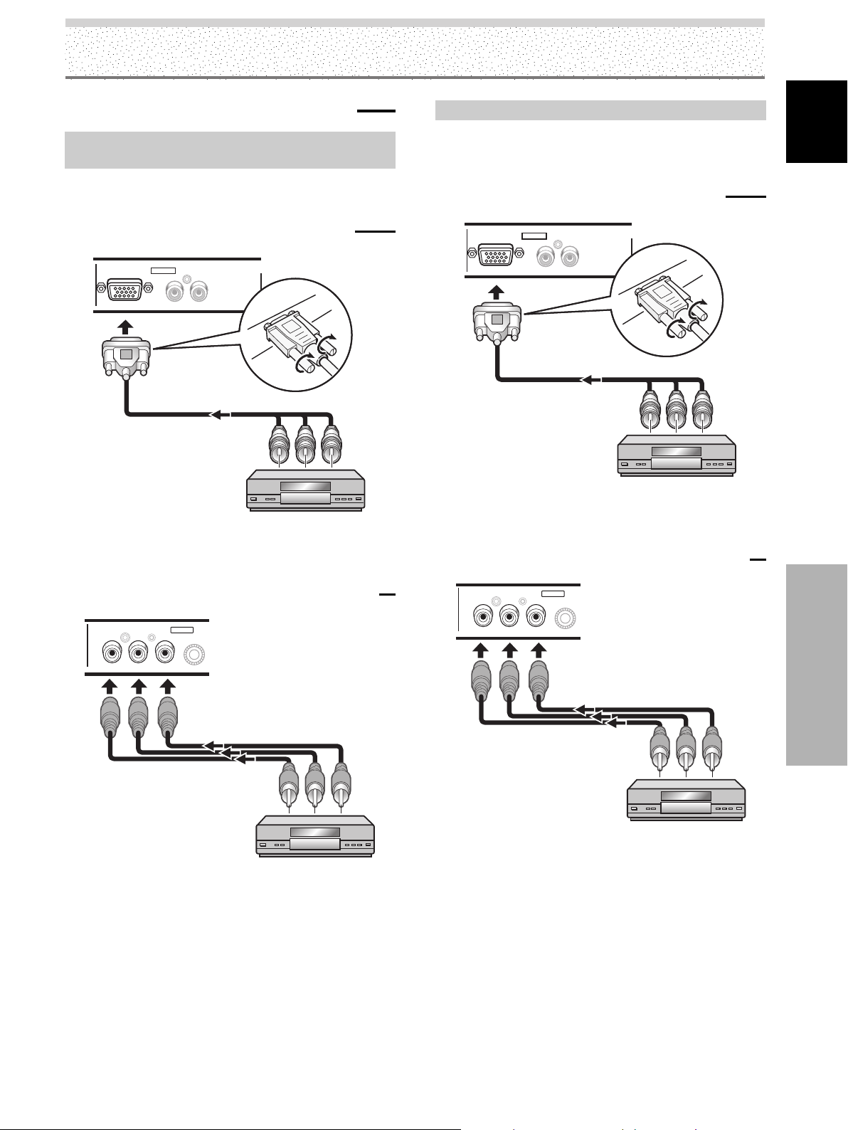
Connection to AV component equipped with
component video jacks
Make component video connections for AV components
equipped with component video jacks.
When connecting to ANALOG RGB IN (INPUT1)
ANALOG RGB IN
D-Sub
On-screen setup is necessary after connection.
Please see pages 21 to 23.
INPUT1
INPUT1
RL
AUDIO
Connection of G ON SYNC analog RGB source
Make G ON SYNC connections for a component with
output that has the synchronization signal layered on top
of the green signal.
When connecting to ANALOG RGB IN (INPUT1)
ANALOG RGB IN
D-Sub
On-screen setup is necessary after connection.
Please see pages 21 to 23.
When connecting to COMPONENT VIDEO (INPUT5)
INPUT1
INPUT1
AUDIO
RL
English
When connecting to COMPONENT VIDEO (INPUT5)
COMPONENT
VIDEO
YCB/PB CR/PR
INPUT5
Connect the Y signal to the Y jack, the CB/PB signal to the
C
B/PB jack, and the CR/PR signal to the CR/PR jack.
Note
This unit is designed to support component video signals with
standard, stable signal levels and sync signals. As a result, some
image disruption may be generated during use of various special
trick play functions on video components.
COMPONENT
VIDEO
YCB/PB CR/PR
INPUT5
Connect the G ON SYNC signal to the Y jack, the B signal
to the C
B/PB jack, and the R signal to the CR/PR jack.
On-screen setup is necessary after connection.
Please see pages 21 to 23.
Installation and Connections
13
EN
Page 18
Installation and Connections
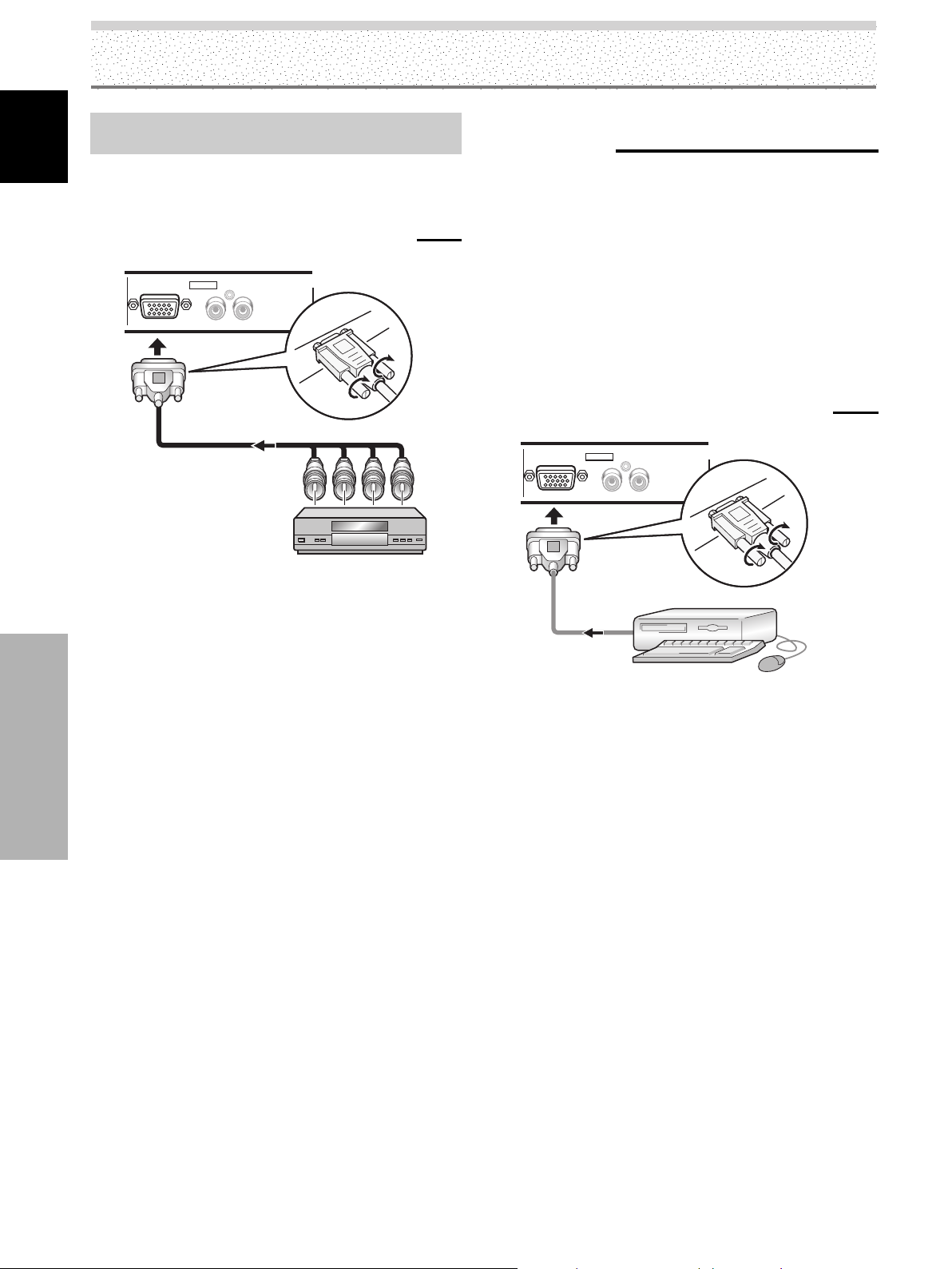
Connection of composite SYNC analog RGB
English
source
Make composite SYNC connections for a component
with output that has the vertical synchronization signal
layered on top of the horizontal synchronization signal.
When connecting to ANALOG RGB IN (INPUT1)
ANALOG RGB IN
D-Sub
INPUT1
INPUT1
RL
AUDIO
Connection to a personal
computer
Connection method differs depending on the computer
type. When connecting, please thoroughly read the
computer’s operating instructions.
Before making connections, be sure to make sure that
the personal computer’s power and display’s main power
is off.
For the PC input signals and screen sizes that the display
is compatible with, please refer to the plasma display’s
Operating Instructions.
When connecting to ANALOG RGB IN (INPUT1)
ANALOG RGB IN
D-Sub
INPUT1
INPUT1
AUDIO
RL
On-screen setup is necessary after connection.
Please see pages 21 to 23.
Installation and Connections
Connect the cable corresponding to the shape of the
input terminal on the display and the personal computer’s
output terminal.
Secure by tightening the terminal screws on both units.
On-screen setup is necessary after connection.
Please see pages 21 to 23.
Note
Depending on the type of computer model being connected, a
conversion connector or adapter etc. provided with the computer
or sold separately may be necessary.
For details, please read your PC’s instruction manual or consult
the maker or nearest dealer of your computer.
14
EN
Page 19
Installation and Connections
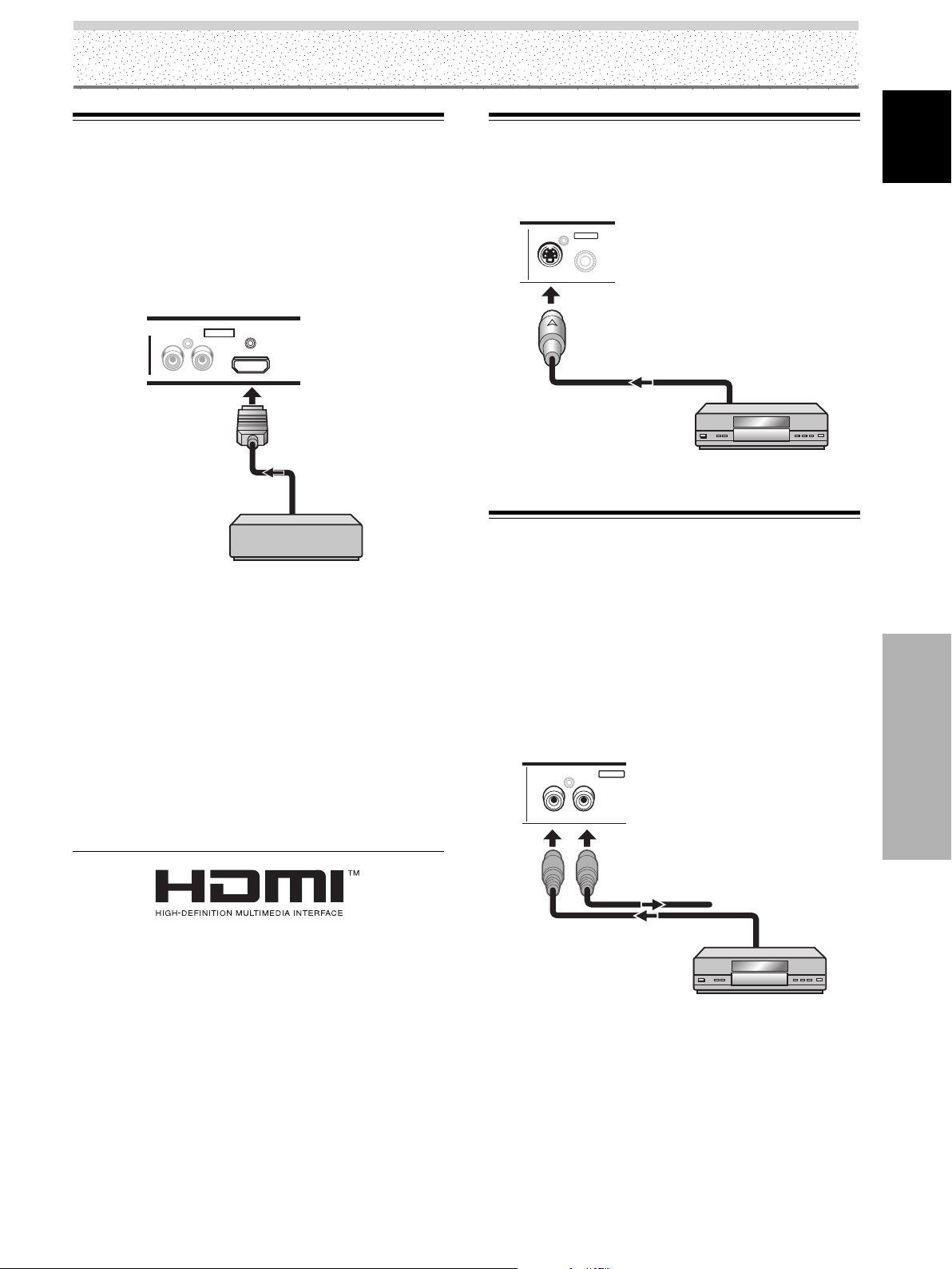
Connection to INPUT2
Connect an AV component with a digital video output
(digital set top box, DVD player, etc.) compatible with
HDCP (High-bandwidth Digital Content Protection). Before
attempting to connect one of these components, read its
operating instructions to make sure that it can be
connected.
AUDIO
INPUT2
RL
After connection is made, on-screen setup is necessary
to match the connected component. Please see page 23
to 24.
Notes
÷ Use a HDMI (High Definition Multimedia Interface) cable for
connection.
÷ When connecting a component with DVI connector, use an
DVI / HDMI conversion cable to make a connection.
÷ It is not a jack intended to be used with a personal computer.
÷ See appendix 1 (page 46) for information regarding signal and
display formats supported by INPUT2.
HDMI
AV component with a
digital video output
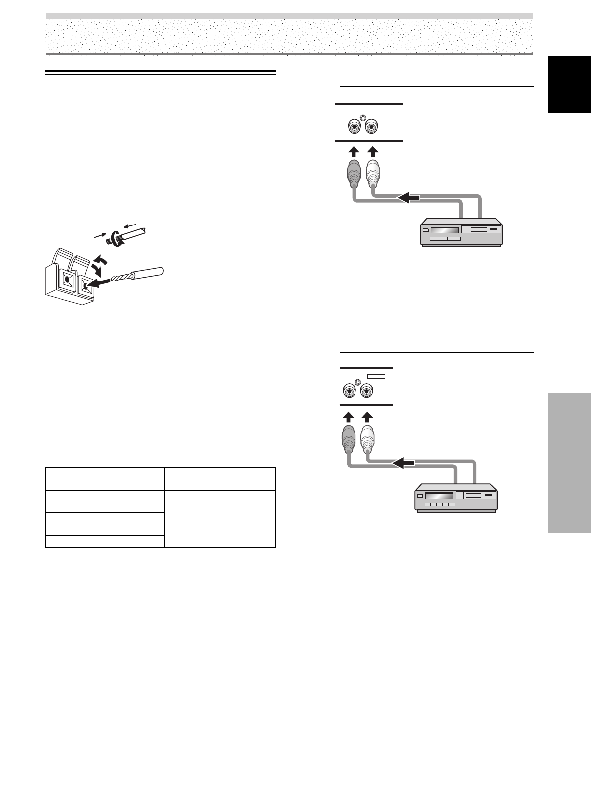
Connection to INPUT3
Connect an AV component that has S-video output jack to
S-VIDEO (INPUT3) jack.
INPUT3
S-VIDEO
AV component
Connection to INPUT4
Connect an AV component that has a video output jack to
INPUT4 jack. The VIDEO OUT (INPUT4) jack can be used
to output the video signal to a separate monitor, recording
device or other component with video input capability.
Note
A video signal will not be output from the VIDEO OUT (INPUT4)
jack when the main power of this display is off or in standby
mode.
VIDEO
IN OUT
INPUT4
English
Installation and Connections
HDMI, the HDMI logo and High-Definition Multimedia Interface are
trademarks or registered trademarks of HDMI Licensing LLC.
To a monitor or a
recording device
AV component
15
EN
Page 20
Installation and Connections
About DTV Set Top Box Connection
English
To ensure proper connection, please carefully read the
instruction manual supplied with the DTV set top box.
The set top box output signals that this display is
compatible with are as follows.
Video
signal type
HDTV
SDTV
Video signal
1080i (1125i)
720p (750p)
480i (525i)
480p (525p)
Video
signal format
Component
RGB
Digital
Composite
S-Video
Component
RGB
Digital
Component
RGB
Digital
INPUT1
Jacks where connection is possible
INPUT4INPUT3INPUT2
INPUT5
Installation and Connections
16
EN
Page 21
Audio connections
Before making connections, be sure to check that the
audio component’s power and the unit’s main power is
off.
Connecting the speakers
This unit is equipped with a 7W + 7W internal amplifier. If
speakers are to be connected to the unit, following the
accompanying connection instructions.
Installation and Connections
Audio connection for component connected to
INPUT1
AUDIO
INPUT1
INPUT1
RL
English
12 mm
Twist exposed
wire strands
together.
Push tab to the open
position, and insert the
wire. Then, close tab
firmly to secure the wire
in place.
Notes
÷ After connecting the wires, pull gently on the cables to confirm
that the wire cores are fastened securely in their terminals.
Insecure connections will result in noise or interrupted sound.
÷ Do not allow the wire cores of the ª and · speaker cables to
protrude excessively, since they may touch each other,
causing a short circuit. This will produce excessive load on the
plasma display, causing operation to malfunction or stop.
Making connections to the audio inputs on this
unit
This unit features five audio inputs. The following chart
shows the video inputs and the corresponding audio input
terminals.
Video
input
INPUT1
INPUT2
INPUT3
INPUT4
INPUT5
Audio input jacks Sound output
Pin jacks (L/R)
Pin jacks (L/R)
Pin jacks (L/R)
Pin jacks (L/R)
Pin jacks (L/R)
Sound of the selected video
input is output from the
SPEAKER (L/R) terminals.
The audio line for the component connected to INPUT1
can be connected to the AUDIO R/L (INPUT1) pin jacks.
Sound is output from the SPEAKER (L/R) terminals
according to the video input selection.
Audio connection for component connected to
INPUT2
AUDIO
INPUT2
RL
The audio line for the component connected to INPUT2
can be connected to the AUDIO R/L (INPUT2) pin jacks.
Installation and Connections
Sound is output from the SPEAKER (L/R) terminals
according to the video input selection.
Note
When using AUDIO INPUT2, set the AUDIO to ANALOG (or
AUTO) (Please see page 24).
17
EN
Page 22
Installation and Connections
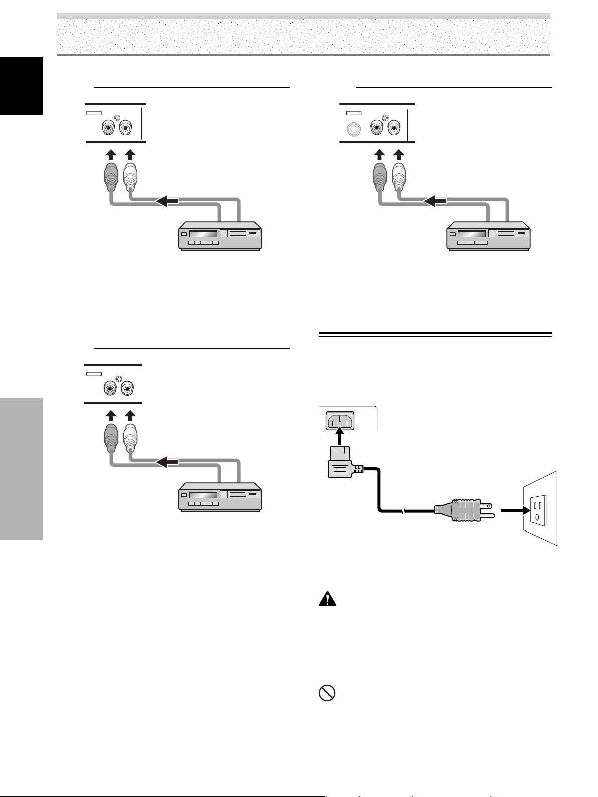
Audio connection for component connected to
INPUT3
English
INPUT3
AUDIO
RL
The audio line for the component connected to INPUT3
can be connected to the Audio R/L (INPUT3) pin jacks.
Sound is output from the SPEAKER (L/R) terminals
according to the video input selection.
Audio connection for component connected to
INPUT4
Audio connection for component connected to
INPUT5
INPUT5
AUDIO
RL
The audio line for the component connected to INPUT5
can be connected to the AUDIO R/L (INPUT5) pin jacks.
Sound is output from the SPEAKER (L/R) terminals
according to the video input selection.
Power Cord Connection
INPUT4
AUDIO
RL
Installation and Connections
The audio line for the component connected to INPUT4
can be connected to the AUDIO R/L (INPUT4) pin jacks.
Sound is output from the SPEAKER (L/R) terminals
according to the video input selection.
Connect the power cord after all component connections
have been completed.
1 Connect the power cord to this unit.
2 Plug the power cord into a power outlet.
CAUTION
÷ Use only the power cord provided.
÷ For the plasma display, a three-core power cord with a ground
terminal is used for efficiency protection. Always be sure to
connect the power cord to a three-pronged grounded outlet
and make sure that the cord is properly grounded. If you use a
power source converter plug, use an outlet with a ground
terminal and screw down the ground line.
18
EN
NO!
÷ Do not use a power supply voltage other than that indicated
(AC 120 V, 60 Hz) as this may cause fire or electric shock.
Page 23
Installation and Connections
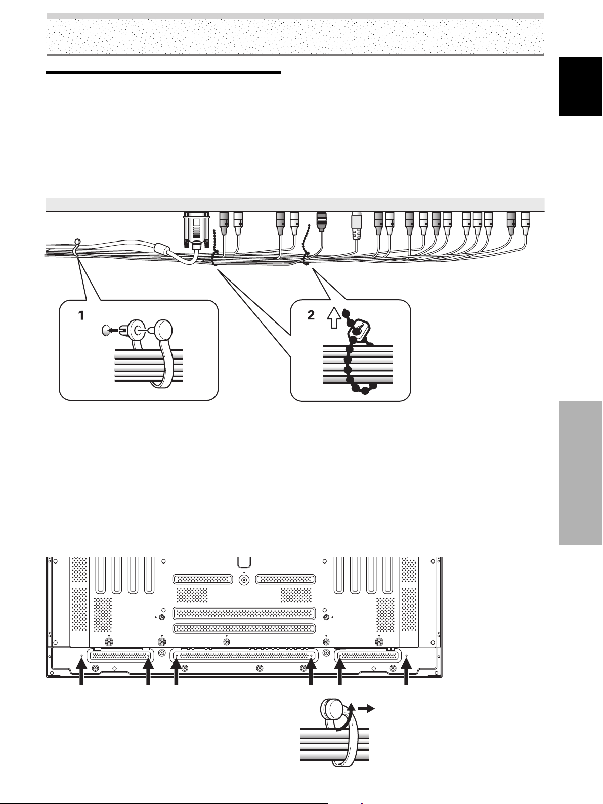
How to Route Cables
Speed clamps and bead bands are included with the
plasma display for bunching cables together. Once
components are connected, follow the following steps to
route cables.
The illustration depicts PDP-5004, PDP-5014, PDP-4304
and PDP-4314 models.
2
1
English
* As viewed from the rear of the display.
1 Organize cables together using the provided
speed clamps.
Insert 1 into an appropriate hole on the rear of the
unit, then snap 2 into the back of 1 to fix the clamp.
Speed clamps are designed to be difficult to undo
once in place. Please attach carefully.
To attach the speed clamps to the display
Connect the speed clamps using the 6 holes marked
with ‡ below, depending on the situation.
To r emove speed clamps
Using pliers, twist the clamp 90° and pull it outward.
In some cases the clamp may have deteriorated over time
and may be damaged when removed.
2 Bunch separated cables together and secure them
with the provided bead bands.
Do not allow excessive stress to be placed on the
ends of cables.
Note
Cables can be routed to the right or left.
The illustration depicts PDP-5004 and PDP-5014 models.
* As viewed from the rear
of the display.
Installation and Connections
19
EN
Page 24
System Settings
Setting the Onscreen Display
English
Language
The onscreen display language has been set to English as
the factory default. To change to another language, the
screen setting must be changed. Follow the procedures
below to change the setting.
All illustrations of the remote control unit explaining
settings and operation are for PDP-5004/PDP-4304.
STANDBY/
ON
MENU
2/3
SET
5/∞
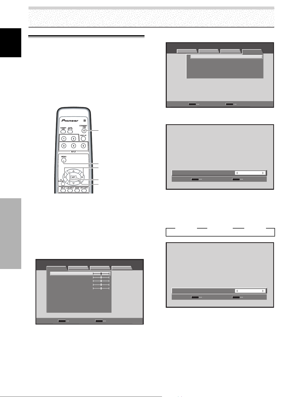
4 Use the 2/3 buttons to select [OPTION].
STANDARD INPUT1
PICTURE SCREEN SETUP OPTION
LANGUAGE ENGLISH
ENERGY SAVE
POWER MANAGEMENT:OFF
AUTO POWER OFF DISABLE
ORBITER OFF
MASK CONTROL ON
SET
ENTER
MENU
:
STANDARD
:
:
:
:
EXIT
5 Use the 5/∞ buttons to select [LANGUAGE], then
press the SET button.
LANGUAGE
SET
SET
:
MENU
ENGLISH
EXIT
Remote control unit
1 Set the rear panel MAIN POWER switch to ON.
The STANDBY indicator on the front panel will light
red.
2 Press the STANDBY/ON button to turn the power
ON.
System Settings
The ON indicator on the front panel will light green.
3 Press the MENU button to display the menu
screen.
STANDARD INPUT1
PICTURE SCREEN SETUP OPTION
CONTRAST
BRIGHTNESS
COLOR
TINT
SHARPNESS
MPEG NR
DNR
CTI
COLOR TEMP. MID
PICTURE RESET
SET
ENTER
:
:
:
:
:
:
:
:
:
0
0
0
0
0
ON
MID
ON
MENU
EXIT
6 Use the 2/3 buttons to select the desired
language.
Each time the 2/3 buttons are pressed, the language
alternates between those available, in the following
order:
3
ENGLISH
LANGUAGE
2 3
SET
SET
FRANÇAIS
2 3
:
MENU
ESPAÑOL
ENGLISH
EXIT
2
7 With the desired language displayed, press the
SET button.
The selected language will be set in memory, and the
screen will return to that shown in step 4.
8 After completing settings, press the MENU button
to return to the normal display.
20
EN
Note
When the onscreen display language is set to any of INPUT 1 to
INPUT 5, the same display language will be set, regardless of the
type of input.
Page 25
Settings After Connections
(INPUT1, 2, 5)
After components have been connected to INPUT1,
INPUT2 or INPUT5, on-screen setup is necessary.
Follow the procedure described below and make settings
as they apply to the type of components connected.
[SIGNAL FORMAT] (INPUT1)/
[COLOR DECODING] setup
(INPUT1, 5)
Notes
÷ These settings are required (for INPUT1) only when providing
input signals with the following refresh rates: 1 31.5 kHz
horizontal / 60 Hz; 2 45 kHz horizontal / 60 Hz vertical; 3 48.4
kHz horizontal / 60 Hz vertical or 56.1 kHz horizontal / 70 Hz
vertical. Adjustment for other signal frequency formats is
performed automatically, so no manual setting is required
(Setting [SIGNAL FORMAT] is not possible).
÷ The [COLOR DECODING] setting is not supported when
inputting a computer signal, or when the [SIGNAL FORMAT]
function has been used to select a signal other than [480p] or
[720p].
÷ Perform [COLOR DECODING] settings individually for INPUT1
or INPUT5.
÷ [SIGNAL FORMAT] setting is possible when only INPUT1 is
selected.
System Settings
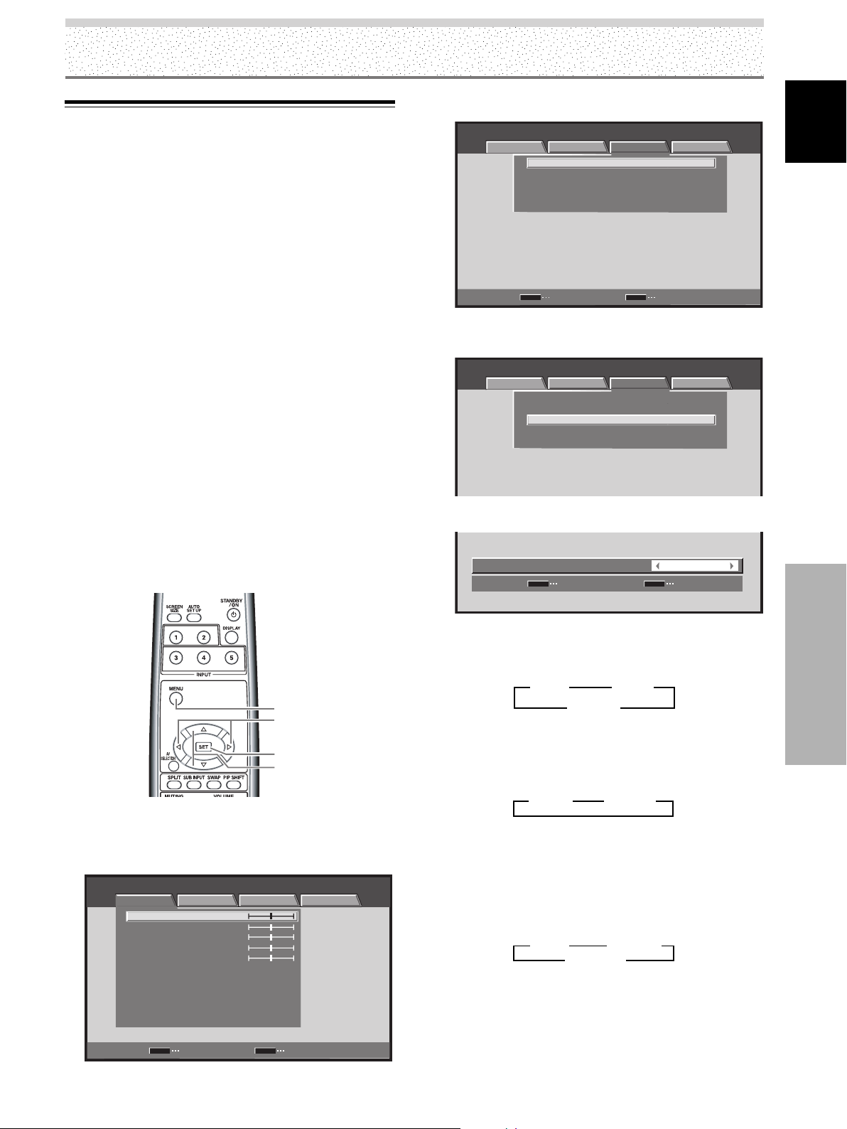
3 Use the 2/3 buttons to select [SETUP].
STANDARD INPUT1
PICTURE SCREEN SETUP OPTION
PURECINEMA
CLAMP POSITION
SIGNAL FORMAT
COLOR DECODING
HDMI INPUT
SET
ENTER
:
OFF
:
AUTO
:
480p
:
COMPONENT
MENU
EXIT
4 Use the 5/∞ buttons to select [SIGNAL FORMAT],
then press the SET button. (INPUT1)
STANDARD INPUT1
PICTURE SCREEN SETUP OPTION
PURECINEMA
CLAMP POSITION
SIGNAL FORMAT
COLOR DECODING
HDMI INPUT
:
OFF
:
AUTO
:
480p
:
COMPONENT
5 Use the 2/3 buttons to select the display mode.
SIGNAL FORMAT
SET
SET
:
MENU
480p
EXIT
English
MENU
2/3
SET
5/∞
Remote control unit
1 Select INPUT1, or INPUT5.
2 Press the MENU button to display the menu screen.
STANDARD INPUT1
PICTURE SCREEN SETUP OPTION
CONTRAST
BRIGHTNESS
COLOR
TINT
SHARPNESS
MPEG NR
DNR
CTI
COLOR TEMP. MID
PICTURE RESET
SET
ENTER
:
:
:
:
:
:
:
:
:
0
0
0
0
0
ON
MID
ON
MENU
EXIT
1 When the input signal has a refresh rate of 31.5 kHz
horizontal / 60 Hz vertical, pressing 2/3 will cause
the display mode to change alternately as follows:
3 480p 2
3 WVGA 2
3 VGA 2
2 When providing input signals with refresh rates of
45 kHz horizontal / 60 Hz Vertical, pressing the 2/3
buttons causes the display mode to alternate as
follows:
3 720-PC 23 720p 2
[720-PC] indicates resolution of 1280 x 720.
3 When the input signal has a refresh rate of 48.4
kHz horizontal / 60 Hz vertical, or 56.1 kHz
horizontal / 70 Hz vertical, pressing 2/3 will cause
the display mode to change alternately as follows:
3 XGA 2 3 WXGA 2
3 PC AUTO 2
If the [PC AUTO] setting is selected, screen
resolution will automatically switch between [XGA]
and [WXGA] as required.
System Settings
21
EN
Page 26
System Settings
Notes
÷ The [PC AUTO] setting supports automatic signal selection only
English
when using RGB separate SYNC inputs.
÷ When G ON SYNC or Composite SYNC signals are input,
selecting [PC AUTO] will cause the screen resolution to be set
to [XGA] only.
÷ When using G ON SYNC or Composite SYNC with WXGA
inputs, set [SIGNAL FORMAT] manually to [WXGA].
6 Press the SET button.
The setting is stored in memory and the screen
returns to that shown in step 4.
7 When a component other than a computer is
connected, use the 5/∞ buttons to select [COLOR
DECODING] then press the SET button (INPUT1 or
INPUT5).
STANDARD INPUT1
PICTURE SCREEN SETUP OPTION
PURECINEMA
CLAMP POSITION
SIGNAL FORMAT
COLOR DECODING
HDMI INPUT
:
OFF
:
AUTO
:
480p
:
COMPONENT
8 Use the 2/3 buttons to select the input signal
format.
9 Press the SET button.
This completes [COLOR DECODING] setting, and
returns you to the display shown in Step 7.
10 After completing settings, press the MENU button
to return to the normal display.
[CLAMP POSITION] setup
(INPUT1, 5)
Depending on the signal, analog RGB signals may result
in the screen image appearing with a whitish or greenish
cast. In such cases, set [CLAMP POSITION] to [LOCKED].
Normally, leave this setting at [AUTO].
MENU
2/3
SET
5/∞
Remote control unit
1
Press the MENU button to display the menu screen.
COMPONENT
COLOR DECODING
SET
SET
:
MENU
EXIT
Each time you press the 2/3 buttons, the setting
changes as follows:
System Settings
3 RGB 23 COMPONENT 2
The table below shows what settings are appropriate
and available for the type of connections made.
Set [SIGNAL FORMAT] and [COLOR DECODING] as follows.
Please take care when making settings. Incorrect settings
can adversely affect the plasma display.
SETUP
Connected
component
Component video output
of a DVD player, etc.
Component video output
from digital tuner, etc.
RGB video output of a
video deck etc., with RGB
output
RGB video output of a PC
SIGNAL
FORMAT
480p
720p
480p
VGA, WVGA,
720-PC,
XGA, WXGA
COMPONENT
COMPONENT
RGB
Not supported
COLOR
DECODING
STANDARD INPUT1
PICTURE SCREEN SETUP OPTION
CONTRAST
BRIGHTNESS
COLOR
TINT
SHARPNESS
MPEG NR
DNR
CTI
COLOR TEMP. MID
PICTURE RESET
SET
ENTER
:
:
:
:
:
:
:
:
:
0
0
0
0
0
ON
MID
ON
MENU
EXIT
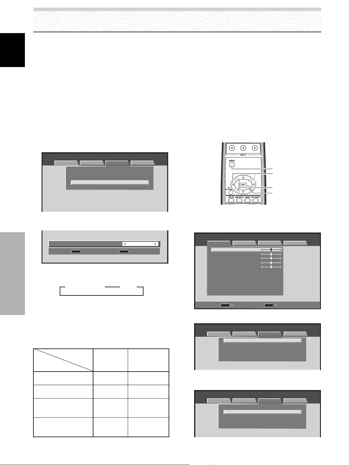
2 Use the 2/3 buttons to select [SETUP].
STANDARD INPUT1
PICTURE SCREEN SETUP OPTION
:
OFF
:
AUTO
:
480p
:
RGB
:
OFF
:
AUTO
:
480p
:
RGB
PURECINEMA
CLAMP POSITION
SIGNAL FORMAT
COLOR DECODING
HDMI INPUT
3
Use the 5/∞ buttons to select [CLAMP POSITION]
then press the SET button.
STANDARD INPUT1
PICTURE SCREEN SETUP OPTION
PURECINEMA
CLAMP POSITION
SIGNAL FORMAT
COLOR DECODING
HDMI INPUT
22
EN
Page 27
4
Use the 2/3 buttons
CLAMP POSITION
SET
to select [LOCKED].
:
SET
MENU
LOCKED
EXIT
The factory default setting is [AUTO].
Each time you press the 2/3 buttons, the setting
changes as follows:
3 AUTO 2
3 LOCKED 2
5 Press the SET button.
This completes [CLAMP POSITION] setting, and
returns you to the display shown in Step 3.
6 After completing settings, press the MENU button
to return to the normal display.
Notes
÷ [CLAMP POSITION] setting is possible only when INPUT1 or
INPUT5 is selected.
÷ When using this setup, be sure to carefully check the signal
output of the component that you are using. For details, please
refer to the instruction manual supplied with the component
you are connecting.
System Settings
2 Use the 2/3 buttons to select [SET UP].
STANDARD INPUT2
PICTURE SCREEN SETUP OPTION
PURECINEMA
CLAMP POSITION
SIGNAL FORMAT
COLOR DECODING
HDMI INPUT
SET
ENTER
MENU
:
:
:
:
OFF
EXIT
3 Use the 5/∞ buttons to select [HDMI INPUT], then
press the SET button.
STANDARD INPUT2
PICTURE SCREEN SETUP OPTION
PURECINEMA
CLAMP POSITION
SIGNAL FORMAT
COLOR DECODING
HDMI INPUT
SET
ENTER
:
:
:
:
MENU
OFF
EXIT
English
Setting HDMI (INPUT2)
Perform setting after completing HDMI connection to
INPUT2.
Follow the procedures below and make settings as they
apply to the type of components connected.
Note
HDMI setting is possible only when INPUT2 is selected.
PICTURE SELECT
This function allows you to switch the input signal format
to automatic or manual when inputting the digital signal.
1 Press the MENU button to display the menu screen.
STANDARD INPUT2
PICTURE SCREEN SETUP OPTION
CONTRAST
BRIGHTNESS
COLOR
TINT
SHARPNESS
MPEG NR
DNR
CTI
COLOR TEMP. MID
PICTURE RESET
SET
ENTER
:
0
:
0
:
0
:
0
:
0
:
ON
:
MID
:
ON
:
MENU
EXIT
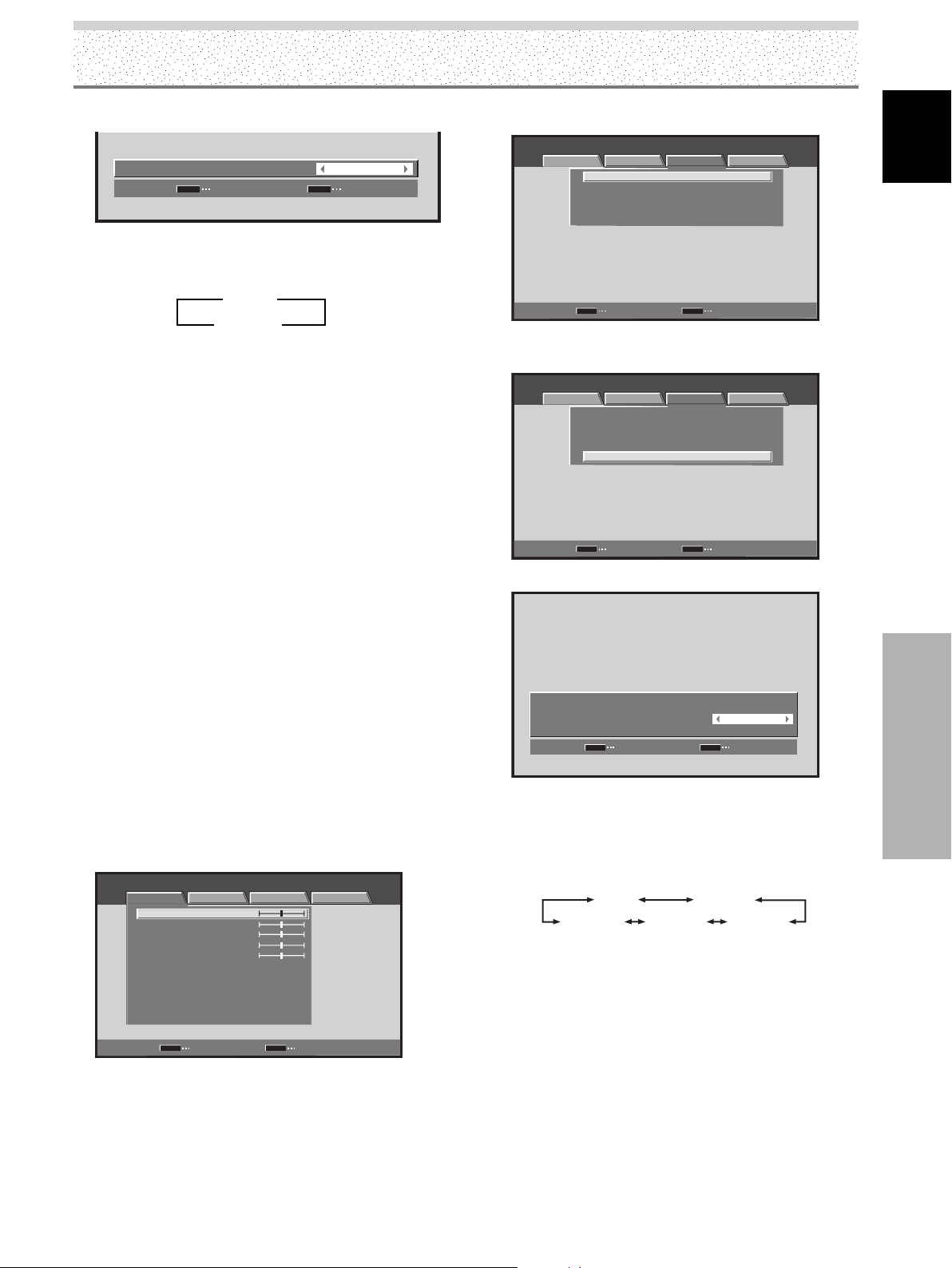
4 Use the 5/∞ buttons to select [PICTURE SELECT].
HDMI INPUT
:
PICTURE SELECT
AUDIO
SET
SET
:
MENU
EXIT
AUTO
AUTO
5 Use the 2/3 buttons to select [PICTURE SELECT]
setting.
The unit has been factory set at the AUTO setting.
Each time you press the 2/3 buttons, the setting
changes as follows:
AUTO
AUTO: Automatically identifies input video signals.
COLOR1: Accepts Y C
COLOR2: Accepts Y C
COLOR3: Select COLOR3 for too dark or distorted
picture when accepts RGB signals.
COLOR4: Select COLOR4 to remove white glare in the
picture when accepts RGB signals.
COLOR1
COLOR2COLOR3COLOR4
B/PB CR/PR (4 : 2 : 2) signals.
B/PB CR/PR (4 : 4 : 4) signals.
System Settings
Note
Even when AUTO is selected, automatic switching may not occur
properly with some input signals. In this event, select COLOR1,
COLOR2, COLOR3 or COLOR4 manually in accordance with the
actual signal input.
23
EN
Page 28
System Settings
6 Press the SET button.
English
This completes [PICTURE SELECT] setting, and
returns you to the display shown in step 3.
7 After completing settings, press the MENU button
to return to the normal display.
AUDIO
This function allows you to switch the audio signal to
automatic or manual when inputting the digital signal.
1 Press the MENU button to display the menu screen.
STANDARD INPUT2
PICTURE SCREEN SETUP OPTION
CONTRAST
BRIGHTNESS
COLOR
TINT
SHARPNESS
MPEG NR
DNR
CTI
COLOR TEMP. MID
PICTURE RESET
SET
2 Use the 2/3 buttons to select [SET UP].
STANDARD INPUT2
PICTURE SCREEN SETUP OPTION
PURECINEMA
CLAMP POSITION
SIGNAL FORMAT
COLOR DECODING
HDMI INPUT
ENTER
:
0
:
0
:
0
:
0
:
0
:
ON
:
MID
:
ON
:
MENU
EXIT
:
OFF
:
:
:
4 Use the 5/∞ buttons to select [AUDIO].
HDMI INPUT
:
PICTURE SELECT
AUDIO
SET
SET
:
MENU
EXIT
AUTO
AUTO
5 Use the 2/3 buttons to select [AUDIO] setting.
The unit has been factory set at the AUTO setting.
Each time you press the 2/3 buttons, the setting
changes as follows:
AUTO
DIGITALANALOG
AUTO: Automatically identifies input audio signals.
DIGITAL: Accept digital audio signals.
ANALOG:Accept analog audio signals.
Note
Even when AUTO is selected, automatic switching may not occur
properly with some input signals. In this event, select DIGITAL or
ANALOG manually in accordance with the actual signal input.
6 Press the SET button.
This completes [AUDIO] setting, and returns you to
the display shown in step 3.
7 After completing setting, press MENU button to
return to the normal display.
SET
ENTER
MENU
EXIT
3 Use the 5/∞ buttons to select [HDMI INPUT], then
System Settings
press the SET button.
STANDARD INPUT2
PICTURE SCREEN SETUP OPTION
PURECINEMA
CLAMP POSITION
SIGNAL FORMAT
COLOR DECODING
HDMI INPUT
SET
ENTER
:
:
:
:
MENU
OFF
EXIT
24
EN
Page 29
Operation
Selecting Input Source
This section explains the basic operation of the plasma
display. Outlined on the following pages is how to turn
the main power on and off, put this display in the
operation or standby mode and how to select connected
components.
Before you begin, make sure you have:
•
Made connections between the plasma display and
AV components or personal computer as described in
the section “Installation and Connections” starting on
page 11.
• Set up the on-screen menu to input signals from
components connected to INPUT1, INPUT2 and
INPUT5 as described in the section “System Settings”
starting on page 20.
If no connections are made to these terminals,
on-screen setup is not necessary.
3 Press the INPUT button on the remote control unit
or the display to select the input.
Input changes each time the display’s INPUT button is
pressed as follows:
3 INPUT1 3 INPUT2 3 INPUT3
INPUT5 2 INPUT4 2
• When the menu screen is displayed, changing the
signal input will cause the menu screen to turn off.
• If the input computer signal is not supported by the
display, the following message will be displayed:
INPUT1
STANDARD
CAUTION
UNSUPPORTED SIGNAL
:
86.7
:
88.5
D-SUB
kHz
HzfV
FULL
fH
1152x864
English
STANDBY/
ON
INPUT
VOLUME
[–/+]
Remote control unit
STANDBY/
ON
INPUT
Display operating panel
VOLUME [–/+]
1 Set the rear panel MAIN POWER switch to ON.
The STANDBY indicator on the front panel will light
red.
2 Press the STANDBY/ON button to turn the power
ON.
The ON indicator on the front panel will light green.
INPUT1
STANDARD
CAUTION
OUT OF RANGE
:
75.7
kHzfH
:
120.0
fV
Hz
D-SUB
FULL
4 Use VOLUME (+/–) buttons on the remote control
unit or the display to adjust the sound volume.
If no audio connections are made to the plasma
display, this step is not necessary.
5 When viewing is finished, press the STANDBY/ON
button to put the display in standby mode.
6 Set the rear panel MAIN POWER switch to OFF.
The STANDBY indicator may continue to light for a
short while even after the main power is turned off.
This is a result of residual electric load impressed on
the circuitry, and the light will turn off presently.
Note
Please do not leave the same picture displayed on the screen for
a long time. Doing so may cause a phenomenon known as
screen burn which leaves a ghost, or residual, image of the
picture on the screen.
Operation
25
EN
Page 30
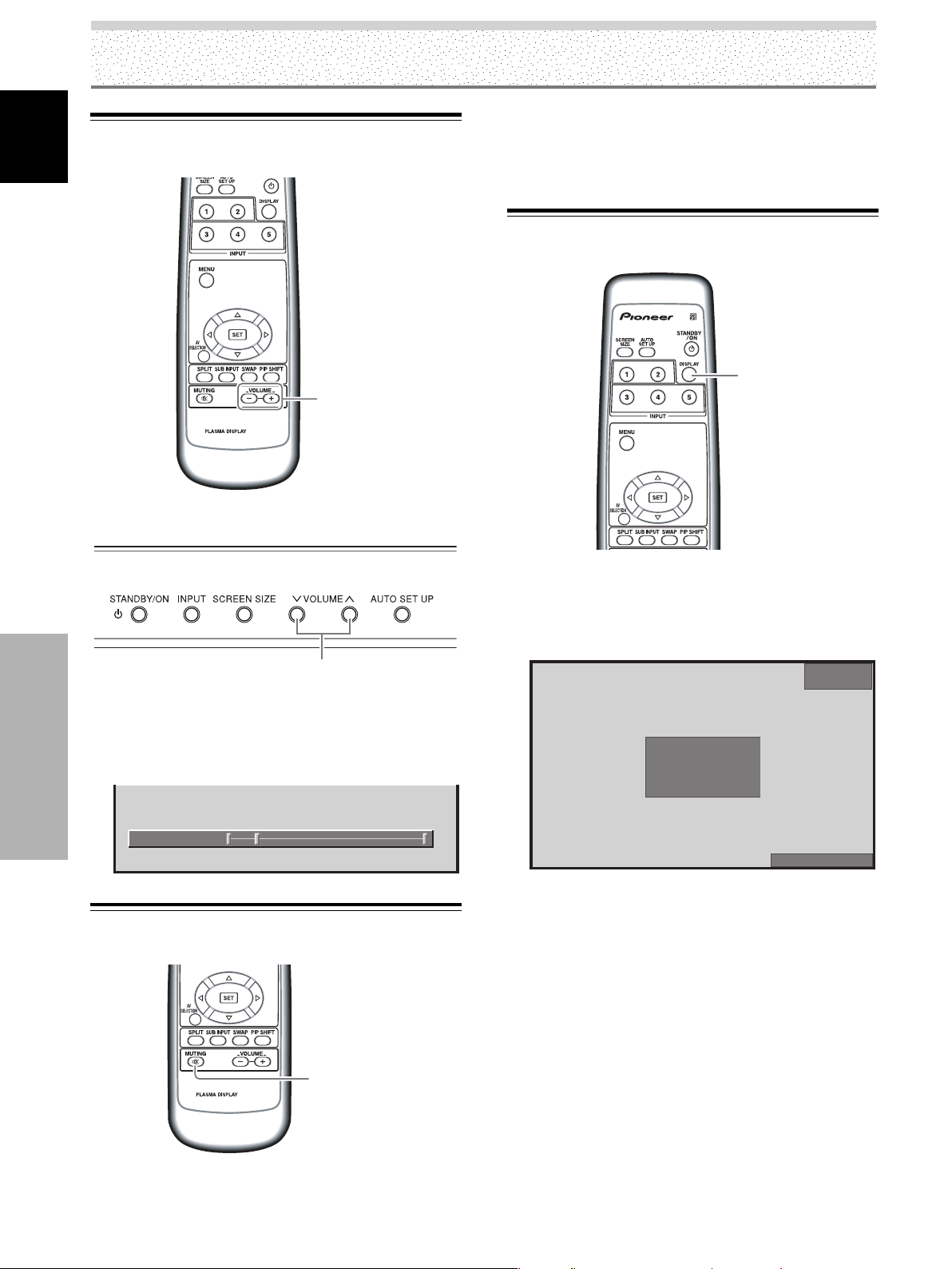
Operation
Adjusting Sound Volume
English
AXD1496
Remote control unit
Press the MUTING button on the remote control
unit.
Press the MUTING button again to restore the sound.
Pressing VOLUME + also quits muting.
Confirming Current Status
DISPLAY
VOLUME
[–/+]
VOLUME [–/+]
Display operating panel
Press the VOLUME buttons.
Press the [–] or [+] button to respectively decrease and
increase the volume of sound from the speakers.
Operation
:
11VOLUME
Muting the Sound
Remote control unit
Press the DISPLAY button.
The currently selected input, AV selection, screen size and
refresh rates will be displayed for about 3 seconds.
INPUT1
STANDARD
:
:
1024
Note
The displayed refresh rates may be slightly different from actual
values.
X
768
D-SUB
k
448
HzfH .
HzfV .
060
DOT BY DOT
26
EN
AXD1496
MUTING
Page 31

Changing Screen Size
This unit incorporates screen modes of various height and
width ratios. For optimal viewing, we recommend that
you select the screen mode that best matches the video
source that you are viewing. Although these modes are
designed for full display of a picture on a wide screen, it is
our hope that you make use of them with a full
understanding of the manufacturer’s intentions.
Operation
During video signal input (INPUT1 to 5)
With INPUT1, 2 and 5, the screen modes you can select
differ depending on the input signal. For details, please
refer to the Supported Video Signal chart on page 46.
3 WIDE 3 4:3
During PC signal input (INPUT1)
3 DOT BY DOT
FULL 2
3 FULL
ZOOM 2CINEMA 2
3 4:3
English
Screen size selection
The size and range of the picture on the screen can be
switched between 5 screen sizes during video signal
input, and 3 sizes during PC signal input.
SCREEN
SIZE
Remote control unit
SCREEN SIZE
Display operating panel
1 Press the SCREEN SIZE button.
The current SCREEN SIZE mode is displayed at the
bottom right of the screen.
The screen modes you can select differ depending on the
input signal. For details, please refer to the Supported
Video Signal chart on page 46, or the Supported PC Signal
chart on pages 47 to 48.
Notes
÷ When the [WIDE], [ZOOM], or [FULL] setting is used to display
a non-wide screen 4:3 picture fully on a wide screen, a portion
of the picture may be cut off or appear deformed.
÷ Be aware that when the display is used for commercial or
public viewing purposes, selecting the [WIDE], [ZOOM],
[CINEMA] or [FULL] mode settings may violate the rights of
authors protected under copyright law.
÷ When [DOT BY DOT] (except with the PDP-5004/PDP-5014 at
1280 x 768 or the PDP-4304/PDP-4314 at 1024 x 768) or [4:3]
screen size is selected, and when MASK CONTROL is ON
(page 40), the display position moves slightly each time the
power is turned on in order to prevent image burning.
During video signal input
How the picture looks
WIDE
4:3
FULL
Suitable for when viewing news or
sports programs. Movies or sports
programs can be viewed with an
expansive powerful image.
Suitable for when viewing news
or sitcoms. The video software
can be viewed in its original
screen frame size.
Suitable for wide screen images
(squeeze).
Operation
2 Press the SCREEN SIZE button again in the
SCREEN SIZE mode indications displayed at the
bottom right of the screen.
The setting changes as follows:
FULL
ZOOM
CINEMA
Mainly suitable for viewing
Cinemascope size and other such
movie images.
Provides a more expansive,
powerful image.
Primarily suitable for viewing
VistaVision cinema sizes.
27
EN
Page 32
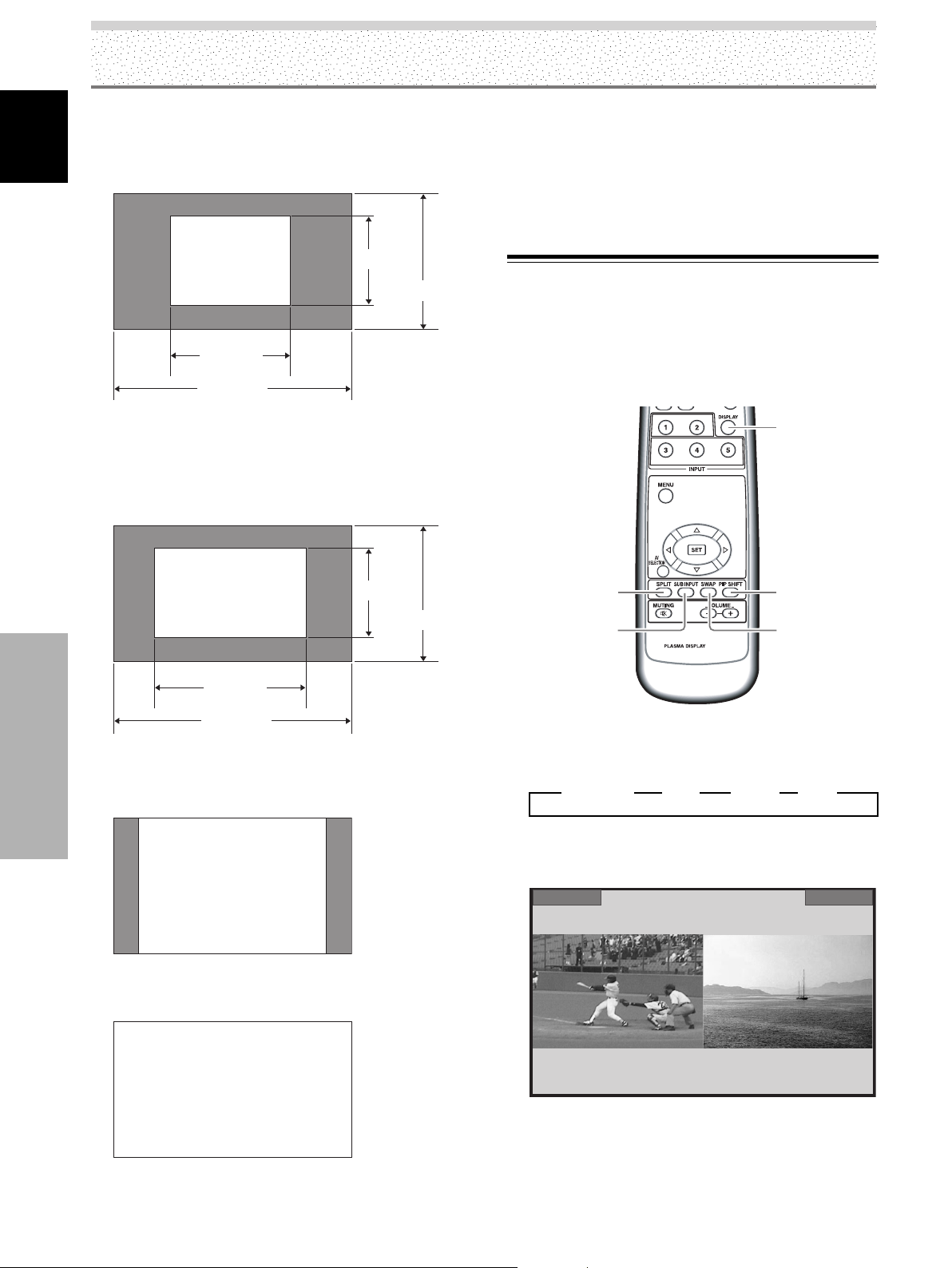
Operation
1 DOT BY DOT
The input signal and the screen maintain a dot to line ratio
English
of 1:1 and is thus highly faithful to the source.
[PDP-5004, PDP-5014]
480 lines
A
640 dots
1280 dots
(Illustration shows 640 x 480 input.)
[PDP-4304, PDP-4314]
* The PDP-4304 and PDP-4314 are designed with
horizontally oblong elements, with the result that
the image displayed will appear more oblong than
the original input signal.
768 lines
Note
When viewing at aspect ratio 4:3 continuously for numerous
hours, or for repeated short periods of time each day, some after
image may be burned into the screen.
To avoid such burning of after images in the screen, use aspect
ratios other than 4:3 whenever possible, unless necessary to
avoid infringement of copyright.
Multiscreen Display
[PDP-5004, PDP-4304 only]
The plasma display’s multiscreen function allows the
simultaneous display of two inputs. The multiscreen
display include three modes, 2-SCREEN, PinP, and PoutP.
DISPLAY
A
640 dots
1024 dots
(Illustration shows 640 x 480 input.)
2 4:3
Operation
The display fills the screen as much as possible without
altering the aspect ratio of the input signal.
A
3 FULL
The display is presented with a widescreen aspect ratio
of 16:9 and fills the entire screen.
480 lines
768 lines
SPLIT
SUB INPUT
AXD1496
1 Press the remote control unit’s SPLIT button.
Each time the button is pressed the multiscreen
display changes in the following order:
3 2-SCREEN 3 PinP 3 PoutP 3 OFF
1 2-SCREEN
The main screen is displayed on the left and the
subscreen on the right.
PIP SHIFT
SWAP
INPUT2INPUT1
A
28
EN
Page 33

Operation
2 PinP
The subscreen is displayed in one of the four corners
of the main screen.
INPUT1
INPUT2
3 PoutP
The subscreen is displayed outside the right side of
the main screen.
INPUT1
INPUT2
To display the currently selected input
Press the DISPLAY button.
If the DISPLAY button is pressed while in multiscreen
mode, the main screen and sub-screen will each be
displayed with its currently selected input.
Notes
¶ When using the plasma display in a profit-making activity, or
when exhibiting images publicly, using the screen size function
to compress or stretch the image may result in infringement of
the copyrights of the image owners.
¶ If the multiscreen display is left on for an extended period of
time, or if the same multiscreen display is repeatedly shown
for short periods on an everyday basis, a residual image
pattern may be burned onto the screen.
¶ When selecting the 2-SCREEN mode, the screen image may
appear somewhat rougher, depending on the source used.
¶ The multiscreen mode will be canceled if a menu is opened.
¶ The screen size cannot be changed during multiscreen display.
¶ The sound of the input selected in the main screen is output
when using the multiscreen function.
¶ Since the main screen uses circuitry providing higher picture
quality than the circuitry for the subscreen, main screen and
subscreen picture quality differs.
¶ When performing picture quality adjustment, there are some
items that do not affect subscreen picture quality.
English
2 Press the remote control unit’s SUB INPUT button
to select the subscreen input source.
To exchange the main screen and subscreen
inputs
Press the remote control unit’s SWAP button.
¶ When 2-SCREEN mode has been selected:
The right and left sides of the display will switch; what
was previously the main screen will now show the
subscreen, and vice versa.
¶ When PinP or PoutP has been selected:
What was previously the main screen image will now
appear in reduced size as the subscreen image, and
vice versa.
To change the position of the subscreen in PinP
mode:
Press the remote control unit’s PIP SHIFT.
Each time the button is pressed, the position of the
subscreen moves in the following order:
3 Lower right 3 Upper right
Lower left 2 Upper left 2
Operation
29
EN
Page 34
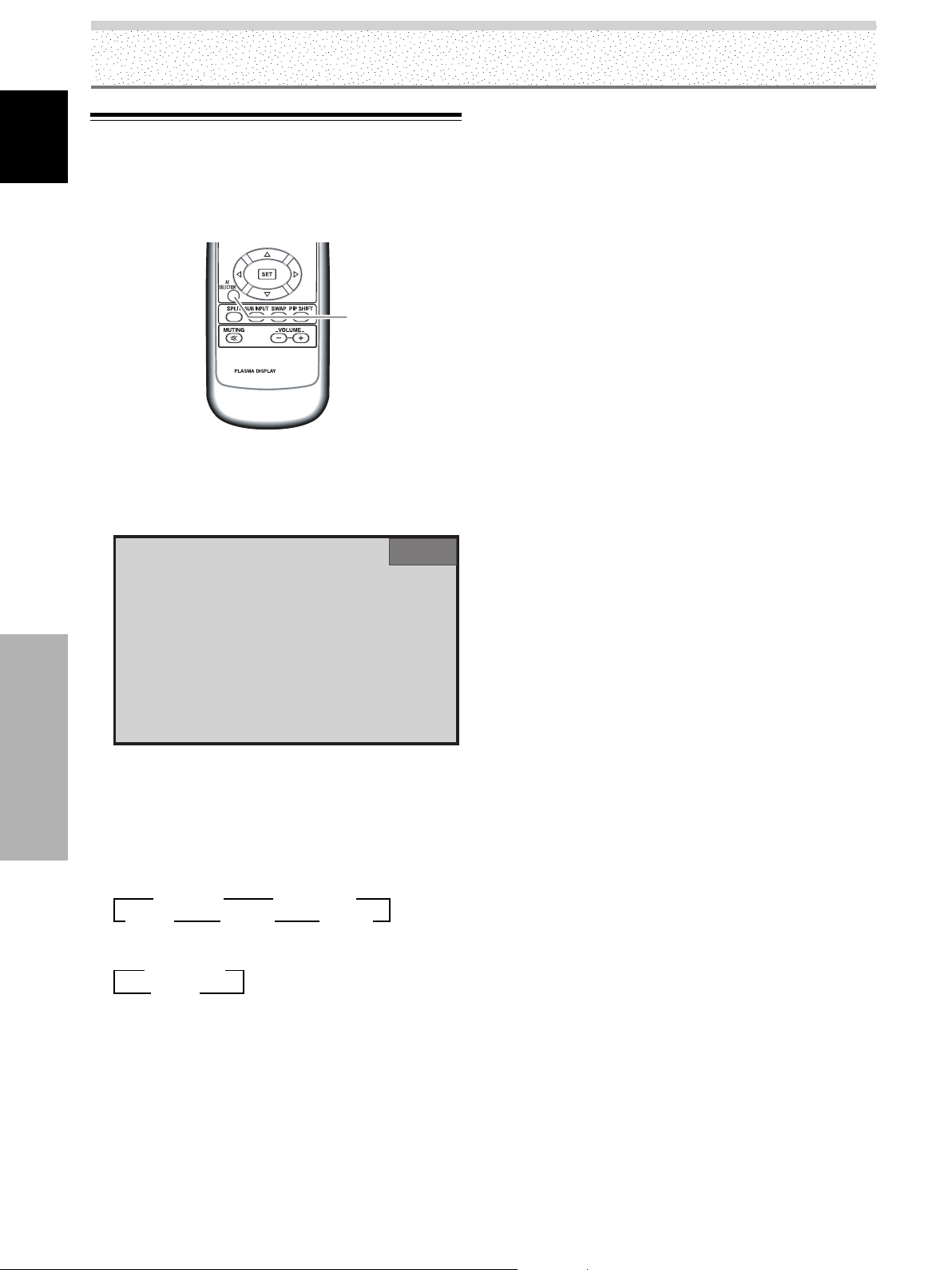
Operation
Setting AV SELECTION
English
To let you enjoy the best picture, you can select between
5 settings during video signal input, and 2 during PC
signal input.
AV
SELECTION
AXD1496
¶ During video signal input
DYNAMIC
......
Raises contrast for bright picture with
strong contrast.
STANDARD
MOVIE
....
............
Provides standard picture quality.
Lowers picture brightness making dark
images like movies easily visible.
............
GAME
Lowers picture brightness making it
easier on the eyes when playing TV
games.
.............
USER
The same setting as STANDARD
when shipped from the factory.
¶ During PC signal input
STANDARD
USER
....
.............
Provides standard picture quality.
The same setting as STANDARD
when shipped from the factory.
Remote control unit
1 Press the AV SELECTION button.
The current AV SELECTION mode is displayed at the
top right of the screen.
2 Press the AV SELECTION button again in the AV
Operation
SELECTION mode indications displayed at the top
right of the screen again.
Each time you press the AV SELECTION button in the
AV SELECTION mode indications displayed at the top
right of the screen, the setting changes as follows:
During video signal input
3 DYNAMIC 3 STANDARD
USER 2 GAME 2 MOVIE 2
During PC signal input
3 STANDARD
USER 2
The factory setting is DYNAMIC for video signal input
and STANDARD for PC signal input. You are
recommended to usually use STANDARD.
INPUT1
STANDARD
You can use each of the AV SELECTION modes as a base,
and make adjustments as desired. For details, please
refer to page 31.
Note
There are times when you cannot switch the AV SELECTION
mode, such as during menu screen display and when there is no
signal input.
30
EN
Page 35
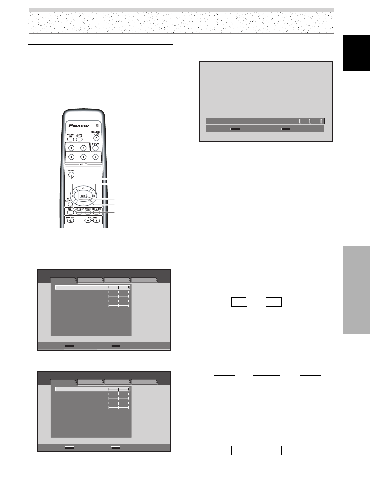
Picture and Screen Adjustment
Picture Adjustment
You can save picture adjustment setting values for each
INPUT and each AV SELECTION mode.
Note
This setting is not possible when in the DYNAMIC mode in [AV
SELECTION].
MENU
2/3
SET
5/∞
AV
SELECTION
Remote control unit
1 Press the AV SELECTION button to select the
desired mode (Refer to page 30).
2 Press the MENU button to display the menu.
STANDARD INPUT1
PICTURE SCREEN SETUP OPTION
CONTRAST
BRIGHTNESS
COLOR
TINT
SHARPNESS
MPEG NR
DNR
CTI
COLOR TEMP. MID
PICTURE RESET
SET
ENTER
3 Use the 5/∞ buttons to select the item, then press
the SET button.
STANDARD INPUT1
PICTURE SCREEN SETUP OPTION
CONTRAST
BRIGHTNESS
COLOR
TINT
SHARPNESS
MPEG NR
DNR
CTI
COLOR TEMP. MID
PICTURE RESET
SET
ENTER
:
:
:
:
:
:
:
:
:
:
:
:
:
:
:
:
:
:
0
0
0
0
0
ON
MID
ON
0
0
0
0
0
ON
MID
ON
MENU
MENU
EXIT
EXIT
4 Use the 2/3 buttons to adjust picture quality to
the desired setting.
:
:
0CONTRAST
MENU
ON
EXIT
SR+MODE
SET
SET
5 Press the SET button.
Adjustment values are saved, and you return to the
display shown in step 3.
6 After completing settings, press the MENU button
to return to the normal display.
¶ Adjustment and setting items during video signal
input
Decrease
CONTRAST ...
BRIGHTNESS ...
COLOR ........
TINT .............
SHARPNESS ...
Contrast becomes weaker Contrast becomes stronger
Picture becomes darker Picture becomes brighter
Colors become weaker Colors become stronger
Skin tones become purplish Skin tones become greenish
Picture becomes softer Picture becomes sharper
MPEG NR
Use when there is mosquito noise in the picture when
viewing a digital broadcast, playing a DVD etc.
Each time you press the 2/3 buttons, the setting
changes as follows:
3 OFF 2
3 ON 2
¶ As you change from OFF 3 ON, the effect becomes
stronger.
DNR
This function reduced graininess to provide a clearer
picture.
Each time you press the 2/3 buttons, the setting
changes as follows:
3 OFF 2 3 LOW 2
3 HIGH 2
¶ As you change from LOW 3 MID 3 HIGH, the effect
becomes stronger.
CTI
This lets you brighten color contour as desired.
Each time you press the 2/3 buttons, the setting
changes as follows:
3 OFF 2
3 ON 2
….
¶ ON
CTI is operating.
¶ OFF …CTI is not operating.
Increase
3 MID 2
31
English
Picture and Screen Adjustment
EN
Page 36

Picture and Screen Adjustment
COLOR TEMP.
Sets white color tone as desired.
English
Each time you press the 2/3 buttons, the setting
changes as follows:
3 LOW 2 3 MID 2
3 HIGH 2
¶ LOW ……… Provides yellowish color tone with low
warmth.
¶ MID ……… Provides natural color tone (Standard).
¶ HIGH ……… Provides a bluish, very warm color tone.
¶ Adjustment items during PC signal input
CONTRAST
BRIGHTNESS
.....
...
Decrease
Contrast becomes weaker Contrast becomes stronger
Picture becomes darker Picture becomes brighter
Increase
Returning to the Original Picture
Adjustment Values
Returning adjusted values to the initial values at the time
of shipment from the factory.
Note
This setting is not possible when in the DYNAMIC mode in [AV
SELECTION].
1 Select the INPUT and AV SELECTION mode for the
values you want to return to the initial factory
settings.
2 Press the MENU button to display the menu.
STANDARD INPUT1
PICTURE SCREEN SETUP OPTION
CONTRAST
BRIGHTNESS
COLOR
TINT
SHARPNESS
MPEG NR
DNR
CTI
COLOR TEMP. MID
PICTURE RESET
SET
ENTER
:
:
:
:
:
:
:
:
:
0
0
0
0
0
ON
MID
ON
MENU
EXIT
3 Use the 5/∞ buttons to select [PICTURE RESET],
then press the SET button.
STANDARD INPUT1
PICTURE SCREEN SETUP OPTION
CONTRAST
BRIGHTNESS
COLOR
TINT
SHARPNESS
MPEG NR
DNR
CTI
COLOR TEMP.
PICTURE RESET
SET
ENTER
:
:
:
:
:
:
:
:
:
0
0
0
0
0
ON
MID
ON
MID
MENU
EXIT
4 Use the 2/3 buttons to select [YES], then press
the SET button.
All the picture adjustment data for the currently
selected INPUT and AV SELECTION mode is reset to
the initial factory settings, and you return to the
display shown in step 3.
Picture and Screen Adjustment
Remote control unit
32
EN
MENU
2/3
SET
5/∞
AV
SELECTION
PICTURE RESET?
YES NO
SET
SET
MENU
EXIT
5 After completing settings, press the MENU button
to return to the normal display.
Note
[PICTURE RESET] only applies to the currently selected INPUT
and AV SELECTION. It cannot be simultaneously applied to
multiple INPUTS and AV SELECTION settings.
Page 37

Adjusting Screen POSITION, CLOCK,
and PHASE (Automatic Adjust)
During PC signal input, by pressing the AUTO SET UP
button on either remote control unit or the unit’s
operating panel, the unit will automatically set the screen
position, clock and phase to best match the current image
input.
When the button is pressed, the optimum
settings are automatically selected for the
current input source.
AUTO
SET UP
Picture and Screen Adjustment
Notes
÷ This setting is supported only when a computer signal is
connected to INPUT1.
÷ Perform this adjustment individually for each signal type.
÷ Optimum settings may not be possible for low-luminance and
certain other signals. In such cases, use the adjustment
methods explained on the this page, “Adjusting Screen
POSITION, CLOCK, and PHASE (Manual Adjust)“.
÷ If you run AUTO SET UP, POSITION, CLOCK and PHASE are
automatically set even if you manually adjust them following
the procedures in the next section.
Adjusting Screen POSITION, CLOCK,
and PHASE
Follow the procedure to save adjustment values for each
INPUT.
(Manual Adjust)
English
Remote control unit
AUTO SET UP
Display operating panel
Press the AUTO SET UP button on either the display
or remote control unit.
AUTO SET UP
MENU
2/3
SET
5/∞
Remote control unit
1 Press the MENU button to display the menu
screen.
STANDARD INPUT1
PICTURE SCREEN SETUP OPTION
CONTRAST
BRIGHTNESS
PICTURE RESET
SET
ENTER
:
0
:
0
MENU
EXIT
Picture and Screen Adjustment
33
EN
Page 38

Picture and Screen Adjustment
2 Use the 2/3 buttons to select [SCREEN].
English
(MENU during PC signal input via INPUT1.)
STANDARD INPUT1
PICTURE SCREEN SETUP OPTION
POSITION
CLOCK
PHASE
SCREEN RESET
SET
ENTER
:
:
:
(MENU during video signal input via INPUT1 through 5.)
STANDARD INPUT1
PICTURE SCREEN SETUP OPTION
POSITION
SCREEN RESET
:
0 0
0
0
MENU
0 0
EXIT
÷ When the [POSITION] item is selected, the 2/3
buttons control movement in the Horizontal
direction (H), and the 5/∞ buttons control
movement in the Vertical direction (V).
POSITION
HV
00
SET
SET
SET
SET
MENU
EXIT
MENU
EXIT
÷ Use the 2/3 buttons for the adjustments of
[CLOCK] and [PHASE].
SET
ENTER
MENU
3 Use the 5/∞ buttons to select the adjustment
item, then press the SET button.
STANDARD INPUT1
PICTURE SCREEN SETUP OPTION
POSITION
CLOCK
PHASE
SCREEN RESET
:
0 0
:
0
:
0
Picture and Screen Adjustment
SET
ENTER
MENU
4 Use the 2/3 and 5/∞ buttons to select the
desired value.
EXIT
EXIT
CLOCK
SET
SET
:
MENU
0
EXIT
5 Press the SET button.
Pressing the SET button writes the value into the
memory and returns the display to the step 3 screen.
6 After completing settings, press the MENU button
to return to the normal display.
Adjustment items during PC signal input
POSITION
H ··························· Adjust the picture’s position to the
left or right.
V···························· Adjust the picture’s position upward
or downward.
CLOCK ···················· Adjust letter breakup or noise on the
screen. This setting adjusts the
display’s internal clock signal
frequency that corresponds to the
input video signal.
PHASE····················· Adjust so that there is minimum
flicker of screen letters or color
misalignment. This setting adjusts
the phase of the internal clock signal
adjusted by the [CLOCK] setting.
34
EN
Page 39
Adjustment items during video signal input
POSITION
H ··························· Adjust the picture’s position to the
left or right.
V ···························· Adjust the picture’s position upward
or downward.
Notes
÷ Setting of [CLOCK] and [PHASE] is possible during PC signal
input via INPUT1.
÷ When the [CLOCK] frequency is changed, the [POSITION]
command’s horizontal [H] option may require readjustment.
÷ If the adjustment items in the [SCREEN] mode are adjusted
excessively, the picture may not be displayed properly.
÷ During video signal input and PC signal input, INPUT1
adjustment values are saved separately.
To r eset [SCREEN] mode settings to the default
1 In step 3 in the previous procedure, use the 5/∞
buttons to select [SCREEN RESET], then press the
SET button.
Picture and Screen Adjustment
English
SCREEN RESET?
YES NO
SET
SET
MENU
EXIT
2 Use the 2/3 buttons to select [YES], and press the
SET button.
All [SCREEN] adjustment values for the selected
INPUT return to the factory settings.
Picture and Screen Adjustment
35
EN
Page 40
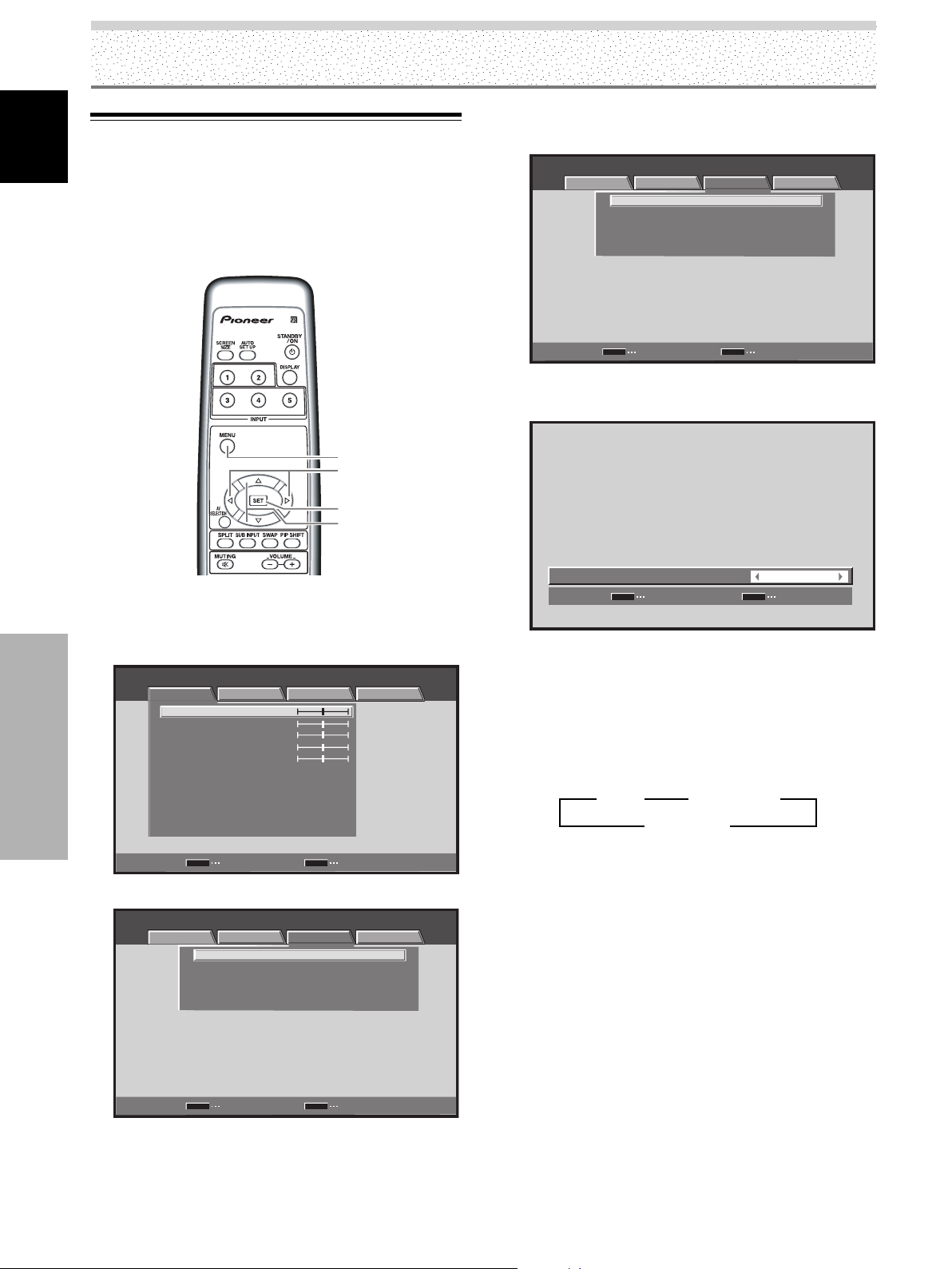
Other Operations
Setting the PURECINEMA Mode
English
Allows even higher fidelity DVD playback of film recordings and
other images.
Note
Make settings individually for each input.
3 Use the 5/∞ buttons to select [PURECINEMA],
and press the SET button.
STANDARD INPUT1
PICTURE SCREEN SETUP OPTION
PURECINEMA
CLAMP POSITION
SIGNAL FORMAT
COLOR DECODING
HDMI INPUT
:
OFF
:
AUTO
:
480p
:
COMPONENT
Remote control unit
1 Press the MENU button to display the menu
screen.
STANDARD INPUT1
PICTURE SCREEN SETUP OPTION
:
:
:
:
:
:
:
:
:
0
0
0
0
0
ON
MID
ON
MENU
Other Operations
CONTRAST
BRIGHTNESS
COLOR
TINT
SHARPNESS
MPEG NR
DNR
CTI
COLOR TEMP. MID
PICTURE RESET
SET
ENTER
2 Use the 2/3 buttons to select [SETUP].
STANDARD INPUT1
PICTURE SCREEN SETUP OPTION
MENU
:
:
:
:
PURECINEMA
CLAMP POSITION
SIGNAL FORMAT
COLOR DECODING
HDMI INPUT
SET
ENTER
MENU
2/3
SET
5/∞
EXIT
OFF
AUTO
480p
COMPONENT
EXIT
SET
ENTER
MENU
EXIT
4 Use the 2/3 buttons to select the desired
[PURECINEMA] mode.
PURECINEMA
SET
SET
:
MENU
Status at the time of factory default setting
During 480p and 720p signal input: OFF
During input of a video signal other than those above:
STANDARD
Each time the button is pressed, the screen mode
setting changes as shown:
[PDP-5004, PDP-4304]
3 OFF 2
3 STANDARD 2
3 ADVANCE 2
¶ OFF ················ [PURECINEMA] function is disabled.
¶ STANDARD ···· When playing DVDs and Hi-Vision
film images recorded at 24 frames/
sec, the recorded data is
automatically detected and
adjustments made to allow optimum
experience of the original beauty of
the film image.
¶ ADVANCE ······ When playing DVDs of film images
recorded at 24 frames/sec, the
recorded video information is
automatically detected and signals
are converted to 72 Hz for playback,
thus recreating the fluid movement
of a movie theater screen, and the
sense of film’s true visual quality.
OFF
EXIT
36
EN
Note
You cannot select [STANDARD] during progressive signal such as
480p or 720p input.
Page 41
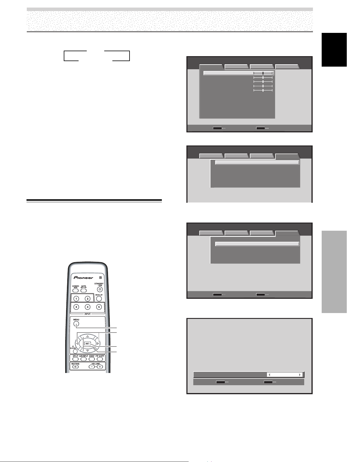
Other Operations
[PDP-5014, PDP-4314]
3 OFF 2
3 STANDARD 2
¶ OFF ················ [PURECINEMA] function is disabled.
¶ STANDARD ···· When playing DVDs and Hi-Vision
film images recorded at 24 frames/
sec, the recorded data is
automatically detected and
adjustments made to allow optimum
experience of the original beauty of
the film image.
Note
You cannot set [PURECINEMA] during progressive signal such as
480p or 720p input.
5 Press the SET button.
The [PURECINEMA] function is set and the screen
returns to that shown in step 3.
6 After completing settings, press the MENU button
to return to the normal display.
Energy Saving Settings
(ENERGY SAVE)
The power control function allows screen brightness to
be suppressed as a means of lowering power
consumption and reducing display deterioration.
1 Press the MENU button to display the menu
screen.
STANDARD INPUT1
PICTURE SCREEN SETUP OPTION
CONTRAST
BRIGHTNESS
COLOR
TINT
SHARPNESS
MPEG NR
DNR
CTI
COLOR TEMP. MID
PICTURE RESET
SET
ENTER
:
:
:
:
:
:
:
:
:
0
0
0
0
0
ON
MID
ON
MENU
EXIT
2 Use the 2/3 buttons to select [OPTION].
STANDARD INPUT1
PICTURE SCREEN SETUP
LANGUAGE ENGLISH
ENERGY SAVE
POWER MANAGEMENT:OFF
AUTO POWER OFF DISABLE
ORBITER OFF
MASK CONTROL ON
OPTION
:
STANDARD
:
:
:
:
3 Use the 5/∞ buttons to select [ENERGY SAVE],
then press the SET button.
STANDARD INPUT1
PICTURE SCREEN SETUP OPTION
LANGUAGE
ENERGY SAVE
POWER MANAGEMENT:OFF
AUTO POWER OFF DISABLE
ORBITER OFF
MASK CONTROL ON
ENGLISH
:
STANDARD
:
:
:
:
English
Remote control unit
MENU
2/3
SET
5/∞
SET
ENTER
MENU
EXIT
4 Press the 2/3 buttons to select [ENERGY SAVE]
setting.
ENERGY SAVE
SET
SET
The factory default setting is [STANDARD].
Each time the 2/3 buttons is pressed, the setting
changes as follows:
:
MENU
STANDARD
EXIT
Other Operations
37
EN
Page 42

Other Operations
3 STANDARD 2
English
3 MODE2 2 3 MODE1 23 MODE3 2
÷ STANDARD ... Brightness is controlled in
accordance with input signal to
produce bright, easily viewed image.
÷ MODE1 ......... Brightness is controlled in
accordance with input signal, but
power consumption is less than that
used in [STANDARD] mode.
÷ MODE2 ......... Brightness is controlled in accordance
with input signal, but power
consumption is less than that used in
[MODE1].
÷ MODE3 ......... Brightness is set at fixed level,
regardless of input signal level.
Effective at reducing screen aging
due to burned lag images, etc.
5 Press the SET button.
[ENERGY SAVE] is set, and you return to the display
shown in step 3.
6 After completing settings, press the MENU button
to return to the normal display.
Note
The [ENERGY SAVE] setting affects all input sources.
INPUT
MENU
2/3
SET
Remote control unit
1 Press the MENU button to display the menu screen.
STANDARD INPUT1
PICTURE SCREEN SETUP OPTION
CONTRAST
BRIGHTNESS
COLOR
TINT
SHARPNESS
MPEG NR
DNR
CTI
COLOR TEMP. MID
PICTURE RESET
:
:
:
:
:
:
:
:
:
0
0
0
0
0
ON
MID
ON
Automatic Power-off
(POWER MANAGEMENT)
The unit is equipped with [POWER MANAGEMENT] and
[AUTO POWER OFF] functions; when set, the function
automatically switches the unit to either standby mode or
Other Operations
power off mode whenever a sync signal is not detected
(a warning message is displayed on the screen before the
functions operate).
Notes
÷ Power Management function setting is only effective and
there is PC signal input via INPUT1.
÷ Setting the Auto Power Off function is only effective in cases
other than the above.
÷ Always turn off the unit’s main power switch when not using
the display for extended periods of time.
SET
ENTER
MENU
EXIT
2 Use the 2/3 buttons to select [OPTION].
STANDARD INPUT1
PICTURE SCREEN SETUP
LANGUAGE ENGLISH
ENERGY SAVE
POWER MANAGEMENT:OFF
AUTO POWER OFF DISABLE
ORBITER OFF
MASK CONTROL ON
OPTION
:
STANDARD
:
:
:
:
3 Use the 5/∞ buttons to select [POWER
MANAGEMENT] or [AUTO POWER OFF], then
press the SET button.
STANDARD INPUT1
PICTURE SCREEN SETUP OPTION
LANGUAGE
ENERGY SAVE
POWER MANAGEMENT:OFF
AUTO POWER OFF DISABLE
ORBITER OFF
MASK CONTROL ON
ENGLISH
:
STANDARD
:
:
:
:
38
EN
SET
ENTER
MENU
EXIT
Page 43
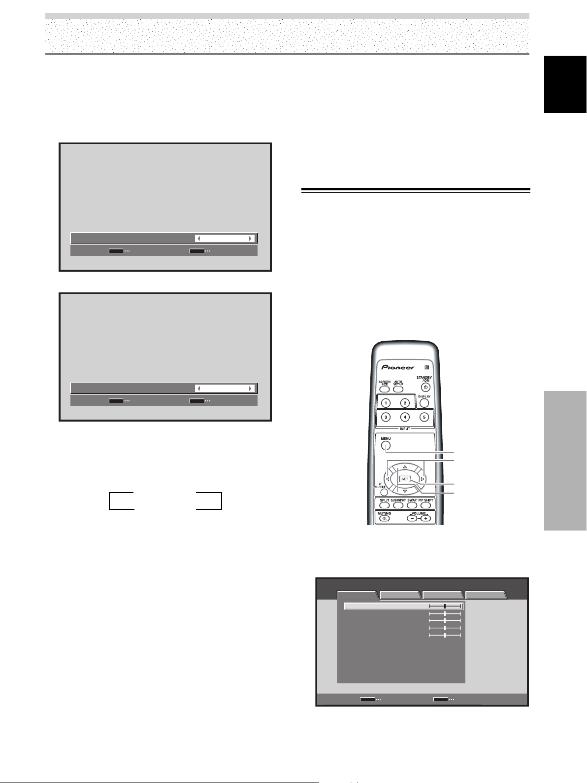
Other Operations
4 Press the 2/3 buttons to confirm selection of the
[POWER MANAGEMENT] or [AUTO POWER OFF].
5 Press the SET button.
[POWER MANAGEMENT] or [AUTO POWER OFF] is
set, and you return to the display shown in step 3.
Selecting POWER MANAGEMENT
POWER MANAGEMENT
SET
SET
Selecting AUTO POWER OFF
:
MENU
OFF
EXIT
To return to operating mode:
÷ To return to normal operation from the [POWER
MANAGEMENT] function’s standby mode, either
operate your computer or press the STANDBY/ON
button on this unit or the remote control unit once.
÷ To return to normal operation from the [AUTO POWER
OFF] function’s power off condition, press the
STANDBY/ON button on the unit or on the remote
control unit.
Setting the Orbiter (ORBITER)
The function gradually moves the display position of the
screen after a set amount of time (approximately every 8
minutes, the screen position is moved at random
horizontally or vertically).
When displaying a still image, setting [ORBITER] to [ON]
helps prevent the screen from being burnt with a lag
image.
÷ This function is not supported when using the
multiscreen function or menu display.
English
AUTO POWER OFF
SET
SET
:
MENU
DISABLE
EXIT
At the time of shipment from the factory, the POWER
MANAGEMENT setting is [OFF], and the AUTO
POWER OFF setting is [DISABLE].
Each time the button is pressed, the setting alternates
as follows:
3 OFF/DISABLE 2
3 ON/ENABLE 2
÷ OFF/DISABLE.....
The unit will continue in operating mode, regardless
of the presence/absence of an input sync signal.
÷ POWER MANAGEMENT: ON.....
If a sync signal is not detected, a warning message is
first displayed for 8 seconds, after which the unit
automatically enters the standby mode, and the
STANDBY indicator lights red. If a sync signal (*1) is
input again later, the unit automatically returns to
normal operating mode.
*1 Except when input signal is G ON SYNC or composite
SYNC.
÷ AUTO POWER OFF: ENABLE.....
If no sync signal is detected for 8 minutes or more, a
warning message will be displayed for 30 seconds,
after which the unit’s power will switch to power off
mode.
MENU
2/3
SET
5/∞
Remote control unit
1 Press the MENU button to display the menu
screen.
STANDARD INPUT1
PICTURE SCREEN SETUP OPTION
CONTRAST
BRIGHTNESS
COLOR
TINT
SHARPNESS
MPEG NR
DNR
CTI
COLOR TEMP. MID
PICTURE RESET
SET
ENTER
:
:
:
:
:
:
:
:
:
0
0
0
0
0
ON
MID
ON
MENU
EXIT
Other Operations
6 After completing settings, press the MENU button
to return to the normal display.
39
EN
Page 44

Other Operations
2 Use the 2/3 buttons to select [OPTION].
English
STANDARD INPUT1
PICTURE SCREEN SETUP OPTION
LANGUAGE ENGLISH
ENERGY SAVE
POWER MANAGEMENT:OFF
AUTO POWER OFF DISABLE
ORBITER OFF
MASK CONTROL ON
:
STANDARD
:
:
:
:
Side Mask Position (MASK CONTROL)
When screen size is set to [DOT BY DOT] or [4:3], or when
using multiscreen display, the position of all elements
change slightly each time the power is turned on in order to
alleviate burning of lag images on the screen.
SET
ENTER
MENU
3 Use the 5/∞ buttons to select [ORBITER], and
press the SET button.
STANDARD INPUT1
PICTURE SCREEN SETUP OPTION
LANGUAGE
ENERGY SAVE
POWER MANAGEMENT:OFF
AUTO POWER OFF DISABLE
ORBITER OFF
MASK CONTROL ON
SET
ENTER
MENU
4 Press the 2/3 buttons to activate the setting.
Other Operations
ORBITER
SET
SET
:
MENU
EXIT
ENGLISH
:
STANDARD
:
:
:
:
EXIT
OFF
EXIT
MENU
2/3
SET
5/∞
Remote control unit
1
Press the MENU button to display the menu screen.
STANDARD INPUT1
PICTURE SCREEN SETUP OPTION
CONTRAST
BRIGHTNESS
COLOR
TINT
SHARPNESS
MPEG NR
DNR
CTI
COLOR TEMP. MID
PICTURE RESET
SET
ENTER
:
:
:
:
:
:
:
:
:
0
0
0
0
0
ON
MID
ON
MENU
EXIT
The factory default setting is [OFF].
Each time the button is pressed, the setting alternates
as follows:
3 OFF 2
3 ON 2
5 Press the SET button.
[ORBITER] is set, and you return to the display shown
in step 3.
6 After completing settings, press the MENU button
to return to the normal display.
Note
The [ORBITER] setting affects all input sources.
40
EN
2 Use the 2/3 buttons to select [OPTION].
STANDARD INPUT1
PICTURE SCREEN SETUP OPTION
LANGUAGE ENGLISH
ENERGY SAVE
POWER MANAGEMENT:OFF
AUTO POWER OFF DISABLE
ORBITER OFF
MASK CONTROL ON
SET
ENTER
MENU
:
STANDARD
:
:
:
:
EXIT
Page 45

3 Use the 5/∞ buttons to select [MASK CONTROL],
and press the SET button.
STANDARD INPUT1
PICTURE SCREEN SETUP OPTION
LANGUAGE
ENERGY SAVE
POWER MANAGEMENT:OFF
AUTO POWER OFF DISABLE
ORBITER OFF
MASK CONTROL ON
ENGLISH
:
STANDARD
:
:
:
:
Other Operations
English
SET
ENTER
MENU
EXIT
4 Press the 2/3 buttons to activate the setting.
MASK CONTROL
SET
SET
The factory default setting is [ON].
Each time the button is pressed, the setting alternates
as follows:
3 ON 2
3 OFF 2
:
MENU
ON
EXIT
5 Press the SET button.
[MASK CONTROL] is set, and you return to the
display shown in step 3.
6 After completing settings, press the MENU button
to return to the normal display.
Other Operations
Note
The [MASK CONTROL] setting affects all input sources.
41
EN
Page 46

Additional Information
Cleaning
English
Regular cleaning will extend the life and performance of
this unit. The recommended way to clean the display and
related parts is described below.
Before cleaning, be sure to unplug the power cord from
the power outlet.
Cleaning the display panel body and remote
control
Do not under any circumstances use solvents such as
benzine or thinner for cleaner. Use of such liquids may
cause deterioration or peeling of paint from the display or
remote control unit.
Wipe the display and remote control gently with a soft
cloth. In the case of excessive dirt buildup, dampen a soft
cloth with a diluted neutral cleaning detergent and after
wringing the cloth thoroughly, wipe the component and
then dry it with a dry soft cloth.
Cleaning the screen
After dusting, wipe the screen gently using the supplied
cleaning cloth or a soft cloth. Do not use tissue or a rough
cloth. As the surface of the screen is easily scratched, do
not rub it or hit it with a hard object.
Troubleshooting
What may at first seem to be an malfunction, may be
remedied with a quick check.
Please check to see a warning is displayed on the screen.
If displayed, refer to the table below and check the mode.
If there is no display check to see the problem is listed on
page 43. The problem may also be caused by something
other than this unit so please also check the other
components being used such as a video deck. If the
problem can still not be solved please consult the dealer
where this unit was purchased.
About the self diagnosis mode
Messages appear on the center of this unit’s screen to
indicate operation or connection faults. After message
confirmation, check the condition of the unit.
ERROR MESSAGE
CAUTION
OUT OF RANGE
or
CAUTION
UNSUPPORTED SIGNAL
or
SIGNAL NG
¶ The current input signal is
REMEDY
not supported by the unit.
Check the Computer signal
compatibility table on
pages 47 to 48, and change
the computer’s output
signal setting appropriately.
Cleaning the vents
As a general rule, use a vacuum cleaner about once a
month to clean the vents on the rear panel of the display
of dust buildup (set the vacuum cleaner to its weakest
setting when doing this).
Using the unit without cleaning it of dust will cause the
internal temperature to increase, resulting in possible
breakdown or fire.
Additional Information
Vents
Vents
Vents
Illustration depicts PDP-5004 model.
42
EN
WARNING
THERMAL ALERT
SHUT DOWN (**)
WARNING
FAN FAILURE
SHUT DOWN (**)
ERROR
VentsVents
INVALID KEY ENTRY
SHUT DOWN (**)
¶ Turn off main power (page
9).
¶ Is ambient temperature
too high?
¶ Remove any objects
blocking the cooling vents
on the plasma display.
¶ Cooling fan has
malfunctioned.
Immediately turn off
power, remove power plug
from its outlet, and consult
a Pioneer service center or
your dealer.
¶ An invalid operation has
been attempted. Check
input signals, connections
and other settings (for
example, multiscreen).
¶ Turn off main power, wait
for 1-2 minutes, then try
turning power on again. If
problem persists, remove
power plug from its outlet
and consult a Pioneer
service center or your
dealer.
In the above, messages contents indicated by (**)
represent numerals.
Page 47

General problems
Problem Possible Solution
• No power.
• Unit cannot be operated.
•Remote control does not
operate.
• Picture is cut off.
• Strange color, light color, or
dark, or color misalignment.
•Power is suddenly turned off.
• No picture.
Additional Information
English
• Is the power cord disconnected? (page 18)
• Has the MAIN POWER switch been switched on? (page 9)
• External influences such as lightning, static electricity, etc., may cause improper operation. In this
case, operate the unit after first turning the MAIN POWER off/on, or unplugging the power cord
and re-plugging it in after 1 to 2 minutes.
• Are batteries inserted with polarity (+, –) correctly aligned? (page 8)
• Are batteries worn out? (Replace with new batteries.)
• Is any object occluding the remote signal receiver? (page 8)
•Point the remote control unit toward the remote signal receiver when operating (page 8).
• Is the selected screen size correct?
Switch to another screen size (page 27).
• Are [SCREEN] mode adjustments such as picture position made correctly? (pages 27 to 28 and 33
to 35)
•Adjust the picture tone (page 31).
• Is the room too bright?
The picture may look dark in a room that is too bright.
• Is [CLAMP POSITION] setup correct? (page 22)
• Is the [HDMI INPUT] setting appropriate? (Only during HDMI input) (pages 23 to 24).
•The unit’s internal temperature has increased (Air vents are blocked).
Remove any objects blocking vent or clean (page 42).
• Is the [POWER MANAGEMENT] function set to [ON]? (page 38)
• Is connection to other components correct? (pages 13 to 15)
• Has setup been done correctly after connection? (pages 21 to 24)
• Is the correct input selected? (page 25)
• Is a non-compatible signal being input? (pages 46 to 48)
• Is the [PICTURE] setting correct? (page 31)
Problems commonly mistaken as breakdown
Problem Possible Solution
•The screen is displayed in a
small size.
• Letter breakup on screen.
•A sharp sound is sometimes
heard from the cabinet.
• Bright portions of image
appear to be losing intensity.
• Speckles or noise appears on
screen.
• Stripes appear on the screen.
• Sound is heard from inside
the unit.
•Fan isn’t moving.
• Fan speed changes.
• Is the correct screen size selected? (pages 27 to 28 and 33)
• Adjust using [SCREEN] mode on the menu screen (page 33).
If there is still no improvement, this unit may be limiting the displayable range. Check the
Computer signal compatibility table (pages 47 to 48).
• Expansion/contraction caused by surrounding temperature change may result in sound being
heard from the cabinet. This is not a malfunction.
• When the video input signal’s level is too high, the bright portions may appear to be losing their
intensity.
Increase the adjustment level of the contrast and check the picture (page 31).
•May be caused by radio wave interference from appliances with motors such as hair dryers,
electric vacuum cleaners, electric power drills, ignition systems of cars, motorcycles etc., switch
devises such as thermostats etc., neon signs or electrical discharge from power lines etc.
•May be caused by radio wave mingling from TV station, FM station, amateur radios, public radios
(simplified radios) etc., or a nearby personal computer, TV, or video/audio component.
•A strong electromagnetic field may cause picture distortion and similar problems.
• Normal sound of the cooling fan and internal sliding parts of the plasma display panel. Not a
malfunction.
• Fan is set to operate only after ambient temperature exceeds 35˚C (95˚F) (differs depending on
installation conditions). Not a malfunction.
• Fan speed changes automatically in accordance with ambient conditions. Not a malfunction.
Additional Information
43
EN
Page 48

Additional Information
Precautions Regarding Use
English
Panel sticking and after-image lag
• Displaying the same images such as still images for a long
time may cause after-image lagging.
This may occur in the following two cases.
1. After-image lagging due to remaining electrical load
When image patterns with very high peak luminance are
displayed for more than 1 minute, after-image lagging may
occur due to the remaining electric load. The after-images
remaining on the screen will disappear when moving images
are displayed. The time for the after-images to disappear
depends on the luminance of the still images and the time
they had been displayed.
2. After-image (lag image) due to burning
Avoid displaying the same image on the Plasma Display
continuously over a long period of time. If the same image is
displayed continuously for several hours, or for shorter periods
of time over several days, a permanent after-image may
remain on the screen due to burning of the fluorescent
materials. Such images may become less noticeable if moving
images are later displayed, but they will not disappear
completely.
The same kind of burning of a lag image may also be produced
after extended multi-hour use, or recurrent daily use for shorter
periods of a single [4:3] screen size, or [DOT BY DOT] image.
Except in cases where violation of intellectual property rights
may be involved (pages 27 to 28), it is recommended that lagimage burning be avoided by selecting a screen size that
displays images over the entire screen (pages 27 to 28).
• In addition, the [ENERGY SAVE] function (page 37), [ORBITER]
function (page 39), and [MASK CONTROL] function (page 40),
can also be used to reduce the chance of lag image formation.
About the plasma panel’s protection function
The brightness of this display will deteriorate slightly when an
image with little movement such as a photograph or computer
image is continuously displayed. This is caused by the plasma
panel’s protection function which detects images with slight
movement and automatically adjusts brightness to protect the
Additional Information
display, and is not a malfunction.
The screen-saver function begins operating when the display
detects no or little screen movement for a period of about three
minutes; the function is an automatic feature and cannot be
turned OFF.
Pixel failure
The plasma display screen is composed of a high numbers of
tiny pixel elements constructed in a high-precision array, but on
occasion one or more of the pixels may fail to light, or may light
erratically. This is an inevitable by-product of the manufacturing
process and not a malfunction.
Electromagnetic interference
This unit is built in compliance with official standards for
electromagnetic interference, but it nonetheless may produce a
low level of radio noise. This noise may be noticeable if AM
radios, computers, or video appliances are installed too close to
the display. In such cases, remove the affected appliance to a
location where it is not affected.
Additional cautions
• If the power is automatically turned off during operation of this
unit, the following reasons may be the cause.
1 Is the [POWER MANAGEMENT] function or [AUTO
POWER OFF] function set to [ON/ENABLE] ? (page 38).
2 The surrounding temperature has risen above 40˚C (104˚F).
The display should be used within ambient temperature
conditions below 40˚C (104˚F).
3 The internal temperature has risen abnormally due to
blocked cooling vents, overheating of internal electronic
parts, or other factors.
If the power is automatically turned off for a reason other than
the above reasons, there could be a malfunction. In this case,
unplug the power cord from the power outlet and request
repair from your nearest sales outlet.
• The plasma display panel of this unit is very bright and viewing
it a close distance will cause eye strain.
We recommend that you view the screen from a suitable
distance (3 to 6 m).
• In order to protect the panel and internal circuitry, this display
is provided with a cooling fan designed to turn on/off and
change speed automatically in accordance with ambient
temperature conditions (the fan sound will change in
accordance with its speed). The display should be used within
ambient temperature conditions below 40˚C (104˚F).
STANDBY and ON Indicators
When the ON indicator is flashing green, an error message is
indicated. Consult any onscreen messages (page 42) and check
ambient conditions (temperature, etc.) and respond accordingly
(page 43).
If the problem persists, disconnect the power plug and consult
your dealer or a service center.
Other than this, if the power turns off by itself, or refuses to turn
on, or if the STANDBY indicator conditions flashing red, a
malfunction may be indicated. Immediately disconnect the power
plug and consult your dealer or a service center.
Concerning infrared light
In principle, the plasma display radiates infrared light. Depending
on the environment in which the monitor is installed and used,
infrared remote control units for other nearby appliances may fail
to operate properly, or noise may be heard in wireless
headphones. In such cases, move the affected appliance to a
location where its infrared sensor is not affected.
44
EN
Page 49

Specifications
General (PDP-5004/PDP-5014)
Light emission panel .................. 50-inch AC Plasma Panel
109.8 (W) x 62.1 (H) x 126.1 (diagonal) cm
Number of pixels .............................................. 1280 x 768
Power supply ........................................... AC 120 V, 60 Hz
Rated current ............................................................. 3.1 A
Standby power consumption ................................... 0.6 W
External dimensions
.... 1218 (W) x 714 (H) x 98 (D: Not including handles) mm
47-31/32 (W) x 28-1/8 (H) x 3-7/8
(D: Not including handles) in.
Weight ................................................ 41.0 kg (90 lbs. 7 oz)
Operating temperature range........ 0 to 40 °C (32 to 104˚F)
General (PDP-4304/PDP-4314)
Light emission panel .................. 43-inch AC Plasma Panel
95.2 (W) x 53.6 (H) x 109.3 (diagonal) cm
Number of pixels .............................................. 1024 x 768
Power supply ........................................... AC 120 V, 60 Hz
Rated current ............................................................. 2.6 A
Standby power consumption ................................... 0.6 W
External dimensions
.... 1070 (W) x 630 (H) x 98 (D: Not including handles) mm
42-1/8 (W) x 24-13/16 (H) x 3-7/8
(D: Not including handles) in.
Weight............................................. 33.5 kg (73 lbs. 14 oz)
Operating temperature range........ 0 to 40 °C (32 to 104˚F)
Input/output
Video
INPUT1
Input Mini D-sub 15 pin (socket connector)
• RGB signal (G ON SYNC compatible)
RGB ... 0.7 Vp-p/75 Ω/no sync.
HD/VS, VD ... TTL level
/positive and negative polarity
/2.2 kΩ
G ON SYNC
... 1 Vp-p/75 Ω/negative sync.
*Compatible with Microsoft Plug & Play
(VESA DDC1/2B)
• Component video signal
Y ... 1 Vp-p/75 Ω negative sync.
B/PB, CR/PR ... 0.7 Vp-p (color100%)/75 Ω
C
Additional Information
INPUT2
Input HDMI
• Digital signal
3.3V T.M.D.S. /50 Ω
INPUT3
Input S jack (Mini DIN 4 pin)
• Y/C separate video signal
Y . . . 1 Vp-p/75 Ω/negative sync.
C . . . 0.286 Vp-p/75 Ω (NTSC)
INPUT4
Input RCA jack
• Composite video signal
1 Vp-p/75 Ω/negative sync.
Output RCA jack
75 Ω /with buffer
INPUT5
Input RCA jack
• Component video signal
Y…1 Vp-p /75 Ω negative sync.
B/PB, CR/PR…
C
0.7 Vp-p (color 100%) / 75 Ω
• RGB signal
G ON SYNC ...
1 Vp-p/75 Ω/negative sync.
R/B ... 0.7 Vp-p/75 Ω/no sync.
Audio
Input AUDIO INPUT (for INPUT1)
Pin jack (x2)
L/R ... 500 mVrms/more than 10 kΩ
AUDIO INPUT (for INPUT2)
Pin jack (x2)
L/R ... 500 mVrms/more than 10 kΩ
AUDIO INPUT (for INPUT3)
Pin jack (x2)
L/R ... 500mVrms/more than 10 kΩ
AUDIO INPUT (for INPUT4)
Pin jack (x2)
L/R ... 500mVrms/more than 10 kΩ
AUDIO INPUT (for INPUT5)
Pin jack (x2)
L/R ... 500mVrms/more than 10 kΩ
Output SPEAKER
L/R ... 8 – 16 Ω/7 W +7 W (at 8 Ω)
English
Additional Information
45
EN
Page 50
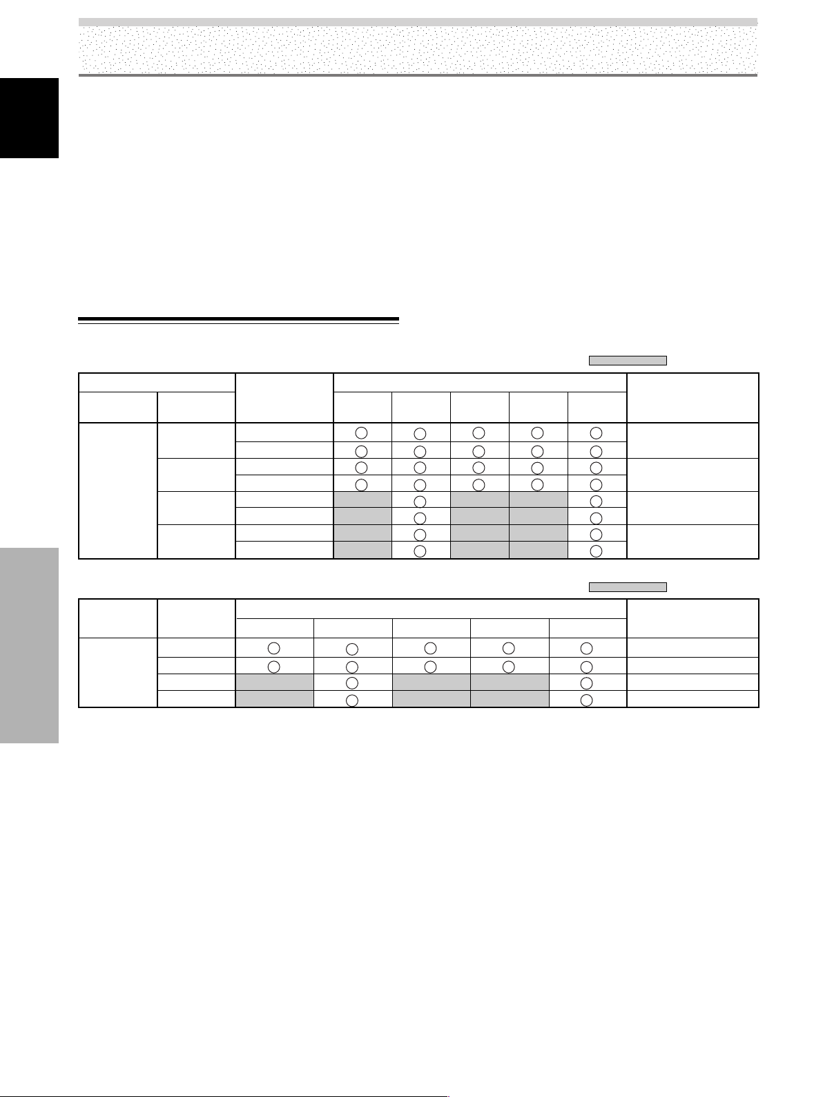
Additional Information
Accessories
Power cord ....................................................................... 1
English
Remote control unit ......................................................... 1
AA (R6) batteries .............................................................. 2
Cleaning cloth (for wiping front panel) ............................. 1
Speed clamps................................................................... 2
Bead bands ...................................................................... 2
Operating Instructions...................................................... 1
Warranty........................................................................... 1
÷ Due to improvements, specifications and design are subject to
change without notice.
Appendix 1
Video signal compatibility table (INPUT1, INPUT5)
Refresh rate
Vertical
fV (Hz)
60
(59.94)
Horizontal
fH (kHz)
15.734
31.5
33.75
45.0
Signal format
Component
RGB
Component
RGB
Component
RGB
Component
RGB
4:3 FULL
Screen size
ZOOM
CINEMA
: Not available.
Remarks
WIDE
480i (525i)/SDTV
480p (525p)/SDTV
1080i (1125i)/HDTV
720p (750p)/HDTV
Digital signal compatibility table (INPUT2)
Vertical
fV (Hz)
60
(59.94)
Additional Information
Aspect Ratio
720x480i
720x480p
1280x720p
1920x1080i
4:3 FULL
Screen size
ZOOM
CINEMA
WIDE
: Not available.
Remarks
480i (525i)/SDTV
480p (525p)/SDTV
720p (750p)/HDTV
1080i (1125i)/HDTV
46
EN
Page 51

Additional Information
Appendix 2
Computer signal compatibility table (PDP-5004/PDP-5014) (INPUT1)
Resolution
(Dot x Line)
640x400
720x400
640x480
848x480
800x600
832x624
1024x768
1280x720
1280x768
Refresh rate
Vertical
56.4Hz
70.1Hz
85.1Hz
60Hz
66.7Hz
72.8Hz
75Hz
85Hz
60Hz
56Hz
60Hz
72Hz
75Hz
85Hz
74.6Hz
60Hz
70Hz
75Hz
(74.9Hz)
85Hz
60Hz
56Hz
60Hz
70Hz
[Meaning of symbols]
Horizontal
DOT BY DOT FULL
24.8kHz
31.5kHz
37.9kHz
31.5kHz
35.0kHz
37.9kHz
37.5kHz
43.3kHz
31.0kHz
35.2kHz
37.9kHz
48.1kHz
46.9kHz
53.7kHz
49.7kHz
48.4kHz
1024x768
56.5kHz
60.0kHz
(60.2kHz)
68.7kHz
44.7kHz
1280x720
45.1kHz
1280x768
47.8kHz
56.1kHz
: Optimal picture. Adjustment of picture position, refresh rate, phase etc., may be necessary.
: Picture will be enlarged but some fine detail will be hard to see.
Screen size (Dot x line)
640x480
±
±
±
±
848x480
800x600
±
±
±
±
832x624
±
±
±
±
±
4:3
1024x768
±
±
±
±
1024x768
±
±
±
±
1024x768
1280x768
1280x768
±
1280x768
±
±
±
±
1280x768
1280x768
±
±
±
±
1280x768
1280x768
±
±
±
1280x768
English
: Not available.
Remarks
NEC PC-9800
NEC PC-9800
Apple Macintosh 13”
(1072x600)
Apple Macintosh 16”
(1376 x 768)
( ) indicates Apple Macintosh 19”
Additional Information
Note
In rare cases, a normal picture may not be obtained when switching between compatible signal formats on the output device (PC).
Should this happen, turn off the power, and then turn it back on again.
47
EN
Page 52

Additional Information
Computer signal compatibility table (PDP-4304/PDP-4314) (INPUT1)
English
Resolution
(Dot x Line)
640x400
720x400
640x480
848x480
800x600
832x624
1024x768
1280x720
1280x768
[Meaning of symbols] : Optimal picture. Adjustment of picture position, refresh rate, phase etc., may be necessary.
Refresh rate
Vertical
56.4Hz
70.1Hz
85.1Hz
60Hz
66.7Hz
72.8Hz
75Hz
85Hz
60Hz
56Hz
60Hz
72Hz
75Hz
85Hz
74.6Hz
60Hz
70Hz
75Hz
(74.9Hz)
85Hz
60Hz
56Hz
60Hz
70Hz
Horizontal
24.8kHz
31.5kHz
37.9kHz
31.5kHz
35.0kHz
37.9kHz
37.5kHz
43.3kHz
31.0kHz
35.2kHz
37.9kHz
48.1kHz
46.9kHz
53.7kHz
49.7kHz
48.4kHz
56.5kHz
60.0kHz
(60.2kHz)
68.7kHz
44.7kHz
45.1kHz
47.8kHz
56.1kHz
: Picture will be enlarged but some fine detail will be hard to see.
: Simple reproduction. Fine detail will not be reproduced.
DOT BY DOT FULL
1024x768
Additional Information
Note
In rare cases, a normal picture may not be obtained when switching between compatible signal formats on the output device (PC).
Should this happen, turn off the power, and then turn it back on again.
Screen size (Dot x line)
640x480
±
±
±
±
848x480
800x600
±
±
±
±
832x624
±
±
±
4:3
768x768
±
±
±
±
768x768
±
±
±
±
768x768
768x768
±
±
±
1024x768
1024x768
±
1024x768
±
±
±
±
1024x768
1024x768
±
±
±
±
1024x768
1024x768
1024x768
±
±
Remarks
NEC PC-9800
NEC PC-9800
Apple Macintosh 13”
(1072x600)
Apple Macintosh 16”
(1376 x 768)
( ) indicates Apple Macintosh 19”
: Not available.
48
EN
Page 53

Appendix 3
INPUT1 (Mini D-sub 15 pin female connector) pin
allocation.
51
6
Input
R
G
B
GND
GND
GND
GND
DDC + 5V
GND
DDC SDA
VD
DDC SCL
Pin No.
1
2
3
4
5
6
7
8
9
10
11
12
13
14
15
10
15 11
NC (No connection)
NC (No connection)
HD or H/V SYNC
Additional Information
Component video signal
General term for video signal format composed of the Y.CBCR,
BPR and Y.B-Y.R-Y luminance signal + color signal.
Y. P
The component video signal is sometimes simply called the color
difference signal.
G ON SYNC
This indicates a video signal in the form of a synchronization
signal added to the G (GREEN) signal of the RGB signal.
VGA
General term for Video Graphics Array.
Generally this indicates a 640 dot x 480 line resolution.
WVGA
General term for Wide Video Graphics Array.
Generally this indicates a 848 dot x 480 line resolution.
XGA
General term for eXtended Graphics Array.
Generally this indicates a 1024 dot x 768 line resolution.
WXGA
General term for Wide eXtended Graphics Array.
Generally this indicates a 1280 dot x 768 line resolution.
English
Explanation of Terms
Aspect ratio
The TV screen’s width to height ratio is referred to as its aspect
ratio. The aspect ratio on standard TVs is 4:3 and on wide TVs or
High Definition TVs it is 16:9.
S jack (S-VIDEO jack)
This jack separates and transmits the video signal as two signals;
the luminance (Y) signal and the color (C) signal. Because of this,
picture reproduction is superior to that obtained at the composite
input/output jacks.
S-video signal
The video signal is composed of two signals; the chroma signal
(color signal) which reproduces color and the luminance signal
which reproduces light and darkness. With standard video
components, these two signals are combined into one and are
handled as a video signal referred to as the composite signal.
The S-video signal, however, is a signal that handles these two
signals separately. Because they are not combined as in the
composite video signal, the high quality of both signals can be
retained.
Published by Pioneer Corporation.
Copyright © 2004 Pioneer Corporation.
All rights reserved.
Additional Information
49
EN
Page 54

Précautions de Sécurité
IMPORTANT
DANGER D´ELECTROCUTION
ATTENTION
NE PAS OUVRIR
Français
Ce symbole de l’éclair, placé dans un
triangle équilatéral, a pour but d’attirer
l’attention de l’utilisateur sur la présence, à
l’intérieur du coffret de l’appareil, de
“tensions dangereuses” non isolées d’une
grandeur suffisante pour représenter un
risque d’électrocution pour les êtres
humains.
ATTENTION:
POUR ÉVITER TOUT RISQUE
D’ÉLECTROCUTION, NE PAS ENLEVER LE
COUVERCLE (NI LE PANNEAU ARRIÈRE).
AUCUNE PIÈCE RÉPARABLE PAR
L’UTILISATEUR NE SE TROUVE À
L’INTÉRIEUR. CONFIER TOUT ENTRETIEN À
UN PERSONNEL QUALIFIÉ UNIQUEMENT.
AVERTISSEMENT
Cet appareil n’est pas étanche. Pour éviter les
risques d’incendie et de décharge électrique, ne
placez près de lui un récipient rempli d’eau, tel
qu’un vase ou un pot de fleurs, et ne l’exposez pas
à des gouttes d’eau, des éclaboussures, de la pluie
ou de l’humidité.
AVERTISSEMENT: EN POSITIONNANT L’EQUIPE-
MENT, S’ASSURER QUE LA FICHE ET LA PRISE DE
RACCORDEMENT DE L’ALIMENTATION SONT FACILEMENT
ACCESSIBLES.
REMARQUE IMPORTANTE
Le numéro de modèle et le numéro de série de ce Téléviseur de
projection figurent sur le panneau arrière.
Veuillez noter le numéro de série sur la carte de garantie ci-jointe et
gardez-la dans un lieu sûr pour la consulter ultérieurement.
Ce point d’exclamation, placé dans un
triangle équilatéral, a pour but d’attirer
l’attention de l’utilisateur sur la présence,
dans les documents qui accompagnent
l’appareil, d’explications importantes du
point de vue de l’exploitation ou de
l’entretien.
D3-4-2-1-1_Fr
Les symboles suivants figurent dans ce manuel
et sur les étiquettes collées sur le produit. Ils
avertissent les utilisateurs et les techniciens qui
travaillent sur cet appareil des conditions
potentiellement dangereuses.
D3-4-2-1-3_A_Fr
AVERTISSEMENT
Ce symbole fait référence à un risque ou à
une pratique dangereuse qui peut provoquer
une blessure grave ou la mort.
ATTENTION
Ce symbole fait référence à un risque ou à
une pratique dangereuse qui peut provoquer
une blessure ou des dégâts matériels.
AVERTISSEMENT: Manipuler le cordon d’alimentation de cet appareil ou les cordons des accessoires prévus, vous expose
au plomb, corps chimique que l’État de Californie et d’autres entités gouvernementales savent capable provoquer des cancers, des
défauts de naissance et d’autres anomalies de la reproduction.
Précautions de Sécurité
Cet appareil a été testé est trouvé conforme avec les limites des appareils numériques de classe B, conformément à l’article 15 du
règlement FCC. Ces limites sont conçues pour offrir une protection raisonnable contre les interférences nuisibles dans une
installation résidentielle. Cet appareil génère, utilise et peut émettre de l’énergie radiofréquence et, s’il n’est pas installé et utilisé
selon les instructions, peut causer des interférences nuisibles aux communications radio. Cependant, il n’y a aucune garantie que
de telles interférences ne se produisent pas pour une installation particulière. Si cet appareil causait des interférences nuisibles à
la réception radio ou télévisée, ce qui peut être déterminé en mettant l’appareil hors et sous tension, vous être encouragé à
essayer de corriger ces interférences à l’aide de l’une ou plusieurs mesures suivantes:
– Réorientez ou déplacez l’antenne réceptrice.
– Augmentez l’espace entre l’appareil est le récepteur.
– Connectez l’appareil sur une prise secteur appartenant à un circuit différent de celui sur lequel le récepteur est connecté.
– Consultez votre revendeur ou un technicien radio/télévision expérimenté.
Avis à l’Utilisateur
Les altérations ou les modifications effectués sans autorisation appropriée peuvent invalider les droits de l’utilisateur à faire
fonctionner l’appareil.
ATTENTION: Ce produit satisfait aux règlements FCC quand des câbles et des connecteurs blindés sont utilisés pour connecter
cet appareil avec les autres appareils. Pour éviter les interférences électromagnétiques avec les appareils électriques tels que des
radios ou des téléviseurs, utilisez des câbles et des connecteurs blindés pour la connexion.
Cet appareil numérique de la classe B est conforme à la norme NMB-003 du Canada.
Lavez vos mains après toute manipulation de ces cordons.
ii
i
FR
Page 55

Remarques sur l’installation:
Ce produit est vendu en assumant qu’il sera installé par un
personnel suffisamment expérimenté et qualifié. Faites toujours
réaliser le montage et l’installation par un spécialiste ou par votre
revendeur.
PIONEER ne peut être tenu responsable pour tout dommage
causé par une erreur d’installation ou de montage, une mauvaise
utilisation ou un désastre naturel.
Nous vous remercions d’avoir acquis cet appareil
PIONEER.
Avant d’utiliser cet écran à plasma, veuillez lire
attentivement les “Précautions de sécurité” et les
“Instructions de fonctionnement” de façon à connaître
comment employer convenablement l’écran à plasma.
Conservez le mode d’emploi pour référence. Vous
pourriez en avoir besoin plus tard.
Remarque pour le revendeur:
Après l’installation, assurez-vous de remettre ce mode d’emploi
à l’utilisateur et de lui expliquer comme utiliser ce produit.
Table des matières
Précautions de Sécurité......................... i
Avant de commencer ............................ 2
Comment utiliser ce mode d’emploi...................... 2
Vérification des accessoires fournis....................... 4
Les différents organes et leurs rôles ... 5
Appareil .................................................................... 5
Boîtier de télécommande ........................................ 6
Panneau de raccordement ...................................... 9
Installation et raccordements .............11
Installation de l’appareil ........................................ 11
Quelques mots sur les prises d’entrée
de l’appareil............................................................ 12
Raccordement aux entrées INPUT1 et
INPUT5.................................................................... 12
Raccordement à INPUT2 ....................................... 15
Raccordement à INPUT3 ....................................... 15
Raccordement à INPUT4 ....................................... 15
Quelques mots sur le raccordement d’un
téléviseur numérique ou d’un décodeur ............. 16
Raccordements audio............................................ 17
Raccordement du cordon d’alimentation ............ 19
Comment faire cheminer les câbles..................... 20
Mise en œuvre de l’ensemble ............ 21
Sélection de la langue d’affichage sur l’écran .... 21
Réglages après raccordement (INPUT1, 2, 5)...... 22
Fonctionnement .................................. 27
Choix de la source ................................................. 27
Réglage du niveau d’écoute ................................. 28
Interruption des sons ............................................ 28
Vérification des réglages actuels.......................... 28
Adoption du format d’image ................................ 29
Affichage de plusieurs images ............................. 31
Paramétrage de AV SELECTION ...........................32
Réglage de l’image et de son affichage....
Réglage image ....................................................... 33
Rétablissement des valeurs initiales
des paramètres d’image ....................................... 34
Réglage de POSITION, HORLOGE et PHASE
(Réglage automatique) .......................................... 35
Réglage de POSITION, HORLOGE et PHASE
(Réglage manuel)................................................... 36
33
Autres opérations ................................ 38
Sélection du mode PURECINEMA........................ 38
Réglages d’économie d’énergie
(ÉCONOM. D’ÉNERGIE)......................................... 39
Mise hors tension automatique
(GESTION D’ALIM.) ............................................... 40
Réglage de l’orbiteur (ORBITER) .......................... 41
Position du cache latéral
(CONTRÔLE MASQUE) ......................................... 42
Informations complémentaires .......... 44
Nettoyage ...............................................................44
Guide de dépannage ............................................. 44
Précautions d’utilisation........................................ 46
Témoins STANDBY et ON ..................................... 46
Caractéristiques techniques.................................. 47
Annexe 1................................................................. 48
Annexe 2................................................................. 49
Annexe 3................................................................. 51
Glossaire................................................................. 51
Français
Table des matières
1
FR
Page 56

Avant de commencer
Comment utiliser ce mode d’emploi
Ce mode d’emploi s’organise autour d’explications
classées dans l’ordre qui nous a paru le plus logique à
quelqu’un qui prendrait possession de l’écran à plasma
pour la première fois.
Français
Après avoir déballé l’appareil et vous être assuré que tous
les éléments vous ont été fournis (page 4), il est
souhaitable de prendre connaissance de la section “Les
différents organes et leur rôle” qui débute à la page 5 de
manière à vous familiariser avec l’écran à plasma et avec
son boîtier de télécommande dont les touches et les
commandes seront mentionnées à de nombreuses
reprises tout au long de ce mode d’emploi.
La section “Installation et raccordements”, qui débute à
la page 11, couvre tous les aspects de l’installation de
l’écran à plasma et des raccordements à effectuer avec
les autres appareils de l’installation.
La section “Mise en œuvre de l’ensemble”, qui débute à
la page 21, traite des réglages à réaliser à partir des
menus affichés de façon à intégrer le fonctionnement de
l’écran à plasma à celui des autres appareils de
l’installation. En fonction des raccordements réalisés, il
peut être inutile de lire cette section.
Les autres sections de ce mode d’emploi aborde des
questions de base comme la sélection de la source, et
des points propres à des situations spécifiques qui
exigent des réglages particuliers de l’image pour tenir
compte des appareils associés et des goûts personnels.
Avant de commencer
Quelques mots sur les menus
affichés
Les exemples de menu qui illustrent ce mode d’emploi,
sont tirés des modèles PDP-5004/PDP-5014. Les menus
des PDP-4304/PDP-4314 diffèrent de la manière suivante:
Exemple de menu des PDP-5004/PDP-5014:
STANDARD ENTRÉE1
IMAGE ÉCRAN SETUP OPTION
:
:
:
:
:
:
MARCHE
:
MOYEN
:
MARCHE
:
MOYEN
MENU
:
0
:
0
:
0
:
0
:
0
:
MARCHE
:
MOYEN
:
MARCHE
:
0
0
0
0
0
MENU
SORTIE
ENTRÉE1
CONTRASTE
LUMINOSITÉ
COULEUR
TEINTE
NETTETÉ
MPEG NR
DNR
CTI
TEMP. COULEUR MOYEN
RÉINIT. IMAGE
SET
ENTRÉE
Exemple de menu des PDP-4304/PDP-4314:
STANDARD
IMAGE ÉCRAN SETUP OPTION
CONTRASTE
LUMINOSITÉ
COULEUR
TEINTE
NETTETÉ
MPEG NR
ONR
CTI
TEMP. COULEUR
RÉINIT. IMAGE
SET
ENTRÉE SORTIE
Veuillez noter que le contenu des menus est identique,
qu’il s’agisse des PDP-5004/PDP-5014 ou des PDP-4304/
PDP-4314.
Apple et Macintosh sont des marques déposées par Apple Computer, Inc.
Microsoft est une marque déposée par Microsoft Corporation.
NEC et PC-9800 sont des marques de commerce de NEC Corporation.
VESA et DDC sont des marques déposées par Video Electronics Standards Association.
Power Management et Sun Microsystems sont des marques déposes par Sun Microsystems, Inc.
VGA et XGA sont des marques déposées par International Business Machines Co., Inc.
HDMI, le logo HDMI et High-Definition Multimedia Interface sont des marques de commerce,
déposées ou non, par HDMI Licensing LLC.
TMDS est une marque de commerce de Silicon Image Inc.
Cet appareil est doté des polices FontAvenue® sous licence NEC Corporation. FontAvenue est une
marque déposée par NEC Corporation.
Pour le modèle
destiné aux
États-Unis
2
FR
Page 57

Description des modes
opératoires
Les modes opératoires sont présentés sous la forme
d’étapes numérotées. Les mode démploi mentionnent
les touches du boîtier de télécommande, sauf lorsque ces
touches n’existent que sur l’écran à plasma lui-même. Si
l’écran à plasma possède des touches jouant le même
rôle que celles du boîtier de télécommande, les
opérations peuvent aussi être réalisées au moyen de ces
touches.
L’ exemple qui suit illustre les opérations requises pour
“Réglage image”. Les exemples fournis vous permettent
de vous assurer que les opérations ont été effectuées de
la manière convenable.
Réglage de l’image et de son affichage
Réglage image
Vous pouvez mettre en mémoire les valeurs des
paramètres de l’image que vous avez adoptés, cela pour
chaque ENTRÉE et pour chaque mode de fonctionnement
audiovisuel (AV SELECTION).
Remarque
Ce réglage n’est pas disponible si vous adoptez la valeur
DYNAMIQUE pour le paramètre [AV SELECTION].
Avant de commencer
Remarque
Les pages écran de ces instructions de fonctionnement doivent
être considérées comme des exemples types; des différences
peuvent être constatées dans la pratique en raison du paramètre
concerné, de la source et de divers autres éléments qui
interviennent dans les réglages.
3 Utilisez les touches 5/∞ pour sélectionner le
paramètre, puis appuyez sur la touche SET.
STANDARD ENTRÉE1
IMAGE ÉCRAN SETUP OPTION
CONTRASTE
LUMINOSITÉ
COULEUR
TEINTE
NETTETÉ
MPEG NR
DNR
CTI
TEMP. COULEUR MOYEN
RÉINIT. IMAGE
SET
4 Utilisez les touches 2/3 pour régler le paramètre
d’image à la valeur convenable.
ENTRÉE
:
0
:
0
:
0
:
0
:
0
:
MARCHE
:
MOYEN
:
MARCHE
:
Français
MENU
SORTIE
Français
MENU
2/3
SET
5/∞
AV
SELECTION
Boîtier de télécommande
1 Appuyez sur la touche AV SELECTION pour
sélectionner le mode de fonctionnement désiré
(Reportez-vous à la page 31).
2 Appuyez sur la touche MENU pour afficher la page
de menu.
STANDARD ENTRÉE1
IMAGE ÉCRAN SETUP OPTION
CONTRASTE
LUMINOSITÉ
COULEUR
TEINTE
NETTETÉ
MPEG NR
DNR
CTI
TEMP. COULEUR MOYEN
RÉINIT. IMAGE
SET
ENTRÉE
:
0
:
0
:
0
:
0
:
0
:
MARCHE
:
MOYEN
:
MARCHE
:
MENU
SORTIE
:
:
0CONTRASTE
SR+MODE
SET
VALIDER
5 Appuyez sur la touche SET.
La valeur du paramètre est sauvegardée et la page
affichée au cours de l’opération 3 est rétablie.
6 Lorsque le réglage est achevé, appuyez sur la
touche MENU pour rétablir la page standard.
¶ Réglages des paramètres pour un signal d’entrée
vidéo
CONTRASTE ....
LUMINOSITÉ ...
COULEUR ........
TEINTE .............
NETTETÉ ..........
MPEG NR
Utilisez ce paramètre pour corriger le bruit de l’image
d’une émission numérique, d’un DVD, etc.
Chaque pression sur les touches 2/3, modifie le réglage,
comme suit:
¶ L’effet augmente tandis que la valeur adoptée varie dans
l’ordre ARRÊT 3 MARCHE.
Diminution Augmentation
Le contraste devient plus f Le contraste devient plus
aible fort
L’image devient plus sombre L’image devient plus
Les couleurs deviennent Les couleurs deviennent
plus ternes plus vives
Les chairs deviennent Les chairs deviennent plus
plus rouges vertes
L’image devient plus floue L’image devient plus nette
3 ARRÊT 2
3 MARCHE 2
MENU
lumineuse
ON
SORTIE
33
Avant de commencer
Réglage de l’image et de son affichage
FR
3
FR
Page 58

Avant de commencer
Vérification des accessoires fournis
Assurez-vous que les accessoires suivants vous ont été
fournis.
Français
1 Cordon d’alimentation
2 Boîtier de télécommande
L’illustration représente les
modèles PDP-5004 et PDP-4304.
3 Piles AA (R6) (x 2)
4 Chiffon de nettoyage (pour la face avant)
Avant de commencer
5 Colliers rapides (x 2)
6 Colliers à œil (x 2)
÷ Mode d’emploi
÷ Carte de garantie
4
FR
Page 59

Les différents organes et leurs rôles
5 6 7 98
Appareil
PDP-4304
Appareil
4
4
Français
PDP-5004
1
Panneau de commande de l‘appareil
23
Appareil
1 Capteur de télécommande
Dirigez le boîtier de télécommande vers le capteur de
l’appareil pour être en mesure d’agir sur ce dernier
(page 8).
2 Témoin ON
Ce témoin s’éclaire (couleur verte) lorsque l’écran à
plasma est en service (page 27).
Lorsque ce témoin clignote, un message d’erreur est
affiché par ailleurs (page 46).
3 Témoin STANDBY
Ce témoin s’éclaire (couleur rouge) lorsque l’appareil
est en veille (page 27). Ce témoin clignote pour
signaler la présence d’un message d’erreur (page 46).
4 Poignées
Les écrans à plasma PDP-5004 et PDP-4304 utilisent
des méthodes différentes de fixation de leurs
poignées, mais l’utilisation de ces poignées est la
même.
Panneau de commande de l‘appareil
5 Touche STANDBY/ON
Appuyez sur cette touche pour mettre l’écran en
service ou en veille (page 27).
6 Touche INPUT
Appuyez sur cette touche pour sélectionner l’entrée
(page 27).
7 Touche SCREEN SIZE
Appuyez sur cette touche pour sélectionner le format
de l’image (page 29).
8 Touches VOLUME (+/–)
Lorsque ces touches ne servent pas à préciser la
valeur d’un paramètre, elles agissent sur le niveau
sonore de sortie (pages 27 et 28).
9 Touche AUTO SET UP
Lorsque l’écran reçoit le signal provenant d’un
ordinateur, cette touche permet de choisir
automatiquement la valeur optimale pour les
paramètres [POSITION], [HORLOGE] [PHASE] (page
35).
Les différents organes et leurs rôles
5
FR
Page 60

Les différents organes et leurs rôles
Boîtier de télécommande
[PDP-5004, PDP-4304]
Français
1
2
3
4
5
6
8
9
AXD1496
0
-
=
~7
!
@
4 Touches ADJUST (5/∞/3/2)
Utilisez ces touches pour déplacer le curseur sur les
menus affichés afin de sélectionner un paramètre, et
pour modifier la valeur du paramètre (pages 21 à 43).
5 Touche SET
Appuyez sur cette touche pour choisir une valeur de
paramètre et pour la valider (pages 21 à 43).
6 Touche AV SELECTION
Appuyez sur cette touche pour accéder aux réglages
image.
(En mode VIDEO: DYNAMIQUE, STANDARD,
CINÉMA, JEU, UTILISATEUR.
En mode PC: STANDARD, UTILISATEUR.)
7 Touche SUB INPUT
Tandis que plusieurs images sont affichées sur l’écran,
utilisez cette touche pour sélectionner l’entrée
associée à l’image secondaire (page 31).
8 Touche SPLIT
Appuyez sur cette touche pour afficher plusieurs
images sur l’écran (page 31).
9 Touche MUTING
Appuyez sur cette touche pour couper les sons (page
28).
0 Touche AUTO SET UP
Lorsque l’écran reçoit le signal provenant d’un
ordinateur, cette touche permet de choisir
automatiquement la valeur optimale pour les
paramètres [POSITION], [HORLOGE] [PHASE] (page
35).
Lorsque vous utilisez le boîtier de
télécommande
¶ Évitez de heurter le boîtier de télécommande et de
l’exposer à l’humidité.
Les différents organes et leurs rôles
¶ N’utilisez pas le boîtier de télécommande dans un endroit
où il serait exposé à la lumière directe du soleil, à la chaleur
rayonnée par un radiateur, à une forte humidité.
¶ La portée du boîtier de télécommande diminue au fur et à
mesure que les piles s’usent. Le moment venu, remplacez
toutes les piles par des piles neuves.
1 Touche SCREEN SIZE
Appuyez sur cette touche pour sélectionner le format
de l’image (pages 29 à 30).
2 Touches INPUT
Appuyez sur ces touches pour sélectionner l’entrée
(page 27).
3 Touche MENU
Appuyez sur cette touche pour afficher le menu sur
l’écran, ou l’effacer (pages 21 à 43).
- Touche STANDBY/ON
Appuyez sur cette touche pour mettre l’écran en
service ou en veille (page 27).
= Touche DISPLAY
Appuyez sur cette touche pour connaître la source
appliquée à l’appareil et le mode de fonctionnement
actuels (page 28).
~ Touche SWAP
Lorsque plusieurs images sont affichées sur l’écran,
utilisez cette touche pour passer de l’image principale
à l’image secondaire (page 31).
! Touche PIP SHIFT
En mode “image dans l’image”, utilisez cette touche
pour choisir l’emplacement que doit occuper l’image
secondaire (page 31).
@ Touches VOLUME (+/–)
Utilisez ces touches pour régler le niveau sonore de
sortie (pages 27 et 28).
6
FR
Page 61

Les différents organes et leurs rôles
[PDP-5014, PDP-4314]
1
2
3
4
5
6
7
8
9
0
-
1 Touche SCREEN SIZE
Appuyez sur cette touche pour sélectionner le format
de l’image (pages 29 à 30).
2 Touches INPUT
Appuyez sur ces touches pour sélectionner l’entrée
(page 27).
3 Touche MENU
Appuyez sur cette touche pour afficher le menu sur
l’écran, ou l’effacer (pages 21 à 43).
4 Touches ADJUST (5/∞/3/2)
Utilisez ces touches pour déplacer le curseur sur les
menus affichés afin de sélectionner un paramètre, et
pour modifier la valeur du paramètre (pages 21 à 43).
5 Touche SET
Appuyez sur cette touche pour choisir une valeur de
paramètre et pour la valider (pages 21 à 43).
6 Touche AV SELECTION
Appuyez sur cette touche pour accéder aux réglages
image.
(En mode VIDEO: DYNAMIQUE, STANDARD,
CINÉMA, JEU, UTILISATEUR.
En mode PC: STANDARD, UTILISATEUR.)
Français
Lorsque vous utilisez le boîtier de
télécommande
¶ Évitez de heurter le boîtier de télécommande et de
l’exposer à l’humidité.
¶ N’utilisez pas le boîtier de télécommande dans un endroit
où il serait exposé à la lumière directe du soleil, à la chaleur
rayonnée par un radiateur, à une forte humidité.
¶ La portée du boîtier de télécommande diminue au fur et à
mesure que les piles s’usent. Le moment venu, remplacez
toutes les piles par des piles neuves.
7 Touche MUTING
Appuyez sur cette touche pour couper les sons (page
28).
8 Touche AUTO SET UP
Lorsque l’écran reçoit le signal provenant d’un
ordinateur, cette touche permet de choisir
automatiquement la valeur optimale pour les
paramètres [POSITION], [HORLOGE] [PHASE] (page
35).
9 Touche STANDBY/ON
Appuyez sur cette touche pour mettre l’écran en
service ou en veille (page 27).
Les différents organes et leurs rôles
0 Touche DISPLAY
Appuyez sur cette touche pour connaître la source
appliquée à l’appareil et le mode de fonctionnement
actuels (page 28).
- Touches VOLUME (+/–)
Utilisez ces touches pour régler le niveau sonore de
sortie (pages 27 et 28).
7
FR
Page 62

Les différents organes et leurs rôles
Français
Portée du boîtier de
télécommande
Lorsque vous vous servez du boîtier de télécommande
pour agir sur l’appareil, vous devez le diriger vers le
capteur de télécommande (Î) qui se trouve sur la face
avant. La portée du boîtier de télécommande est de
l’ordre de 7 m (23 pieds); l’angle par rapport au capteur
de télécommande ne doit pas dépasser 30°.
7 m
(23 pieds)
30°
Mise en place des piles dans le
boîtier de télécommande
Poussez dans la direction de la flèche
tout en appuyant légèrement.
2 piles AA (R6)
AT TENTION
¶ Introduisez les piles de manière que les pôles (+) et (–)
soient en regard des repères gravés dans le logement.
¶ Si vous envisagez de ne pas utiliser le boîtier de
télécommande pendant une longue période (un mois ou
plus), retirez les piles pour éviter qu’elles ne fuient. Si
l’électrolyte a fui, nettoyez soigneusement le logement des
piles puis mettez en place des piles neuves.
Lorsque vous diposez de piles / batteries usées,
veuillez vous conformer aux normes
gouvernementales ou environnementales en
vigueur dans votre pays ou région.
D3-4-2-3-1_Fr
L’illustration
représente les modèles
PDP-5004 et PDP-4304.
En cas de difficulté dans l’utilisation du boîtier
de télécommande
¶ Le boîtier de télécommande peut ne pas agir comme désiré
Les différents organes et leurs rôles
si un objet est interposé en lui et l’écran.
¶ La portée du boîtier de télécommande diminue au fur et à
mesure que les piles s’usent; remplacez les piles par des
piles neuves dès que le besoin s’en fait sentir.
¶ L’écran de l’appareil émet un rayonnement infrarouge. Si
vous placez au voisinage de l’écran un appareil dont le
fonctionnement peut être commandé par des signaux
infrarouges émis par un boîtier de télécommande, la
réception de ces signaux peut être perturbée, voire arrêtée.
Dans cette situation, augmentez la distance entre l’appareil
concerné et l’écran.
¶ En fonction de l’environnement d’installation, les signaux
émis par le boîtier de télécommande peuvent être brouillés
par le rayonnement infrarouge de l’écran à plasma, ce qui
peut gêner leur réception ou réduire la portée du boîtier. La
puissance du rayonnement infrarouge émis par l’écran
dépend de l’image qui y est affichée.
30°
Capteur de
télécommande
NON!
¶ N’utilisez pas tout à la fois une pile neuve et une pile
usagée.
¶ La tension d’une pile peut être différente de l’autre bien
que leur forme soit identique. N’utilisez pas, en même
temps, des piles de type différent.
¶ Ne tentez pas de charger, de court-circuiter, de démonter
une pile; ne la mettez pas en contact avec flamme.
8
FR
Page 63

Panneau de raccordement
Les différents organes et leurs rôles
L’illustration représente les modèles PDP-5004, PDP5014, PDP-4304 et PDP-4314.
INPUT3 INPUT4 INPUT5
S-VIDEO
AUDIO AUDIO AUDIO
VIDEO
RL RL RLYCB/PBCR/P
IN OUT
0 = ~- ! @ #
SPEAKER
8Ω ~16Ω
R
+ –
SERVICE ONLY
COMPONENT
VIDEO
POWER
OFF ON
AC IN
R
ANALOG RGB IN
D-Sub
INPUT1
INPUT1
AUDIO
SPEAKER
8Ω ~16Ω
+ –
987
AUDIO
RLRL
L
Français
INPUT2
HDMI
1
Section de l’écran à plasma
L’écran à plasma est doté de 5 prises d’entrée vidéo,
d’une prise de sortie vidéo, de prises d’entrée audio et de
bornes pour enceintes.
Les instructions de raccordement figurent dans les pages
dont les numéros sont indiqués entre parenthèses.
1 Borne SPEAKER (R)
Pour le raccordement à l’enceinte extérieure droite.
Utilisez une enceinte dont l’impédance est comprise
entre 8 et 16 Ohms.
2 Prise RS-232 (Utilisée lors du réglage à la fabrique)
3 ANALOG RGB IN (INPUT1) (mini D-sub 15 broches)
Pour le raccordement à un appareil pourvu d’une prise
de sortie RGB, par exemple un ordinateur personnel
ou un décodeur RGB; ou encore pour le raccordement
d’un appareil possédant des prises de sortie de
composantes, comme c’est le cas d’un graveur de
DVD. Veillez à ce que la liaison soit compatible avec le
format du signal provenant de l’appareil associé
(pages 13 à 14).
23456
4 AUDIO (INPUT1) (fiche Cinch (RCA))
S’utilise pour obtenir le son quand ENTRÉE1 est
sélectionnée. Raccordez les prises de sortie audio de
l’appareil relié à la prise INPUT1 (page 17).
Remarque
La prise de la voie audio gauche (L) n’est pas compatible avec
les sources monophoniques.
5 AUDIO (INPUT2) (fiches Cinch (RCA))
Sortie des sons lorsque ENTRÉE2 (audio analogique) a
été sélectionnée.
Reliez ces prises aux prises de sortie audio de
l’appareil relié à INPUT2 (page 17).
Remarque
La prise de la voie audio gauche (L) n’est pas compatible avec
les sources monophoniques.
Les différents organes et leurs rôles
9
FR
Page 64

Les différents organes et leurs rôles
6 HDMI (INPUT2) (prise HDMI)
Pour le raccordement à un appareil possédant une
sortie vidéo numérique tel qu’un décodeur, un lecteur
de DVD, etc. et compatible HDCP. Avant de relier un
appareil, lisez le mode d’emploi qui l’accompagne afin
de vous assurer que la liaison peut être réalisée sans
risque (page 15).
Français
(HDCP = High-bandwidth Digital Content Protection)
(HDMI = High Definition Multimedia Interface)
7 Interrupteur MAIN POWER
Utilisez cet interrupteur pour mettre l’écran à plasma
sous tension, ou hors tension.
8 AC IN
Un cordon d’alimentation est fourni avec l’écran;
branchez une extrémité de ce cordon sur cette prise
et l’autre extrémité sur une prise secteur.
9 Borne SPEAKER (L)
Pour le raccordement à l’enceinte extérieure gauche.
Utilisez une enceinte dont l’impédance est comprise
entre 8 et 16 Ohms.
0 S-VIDEO (INPUT3) (Prise S-vidéo)
Pour le raccordement à la prise de sortie S-vidéo d’un
magnétoscope, d’une caméra vidéo, d’un lecteur de
LaserDisc ou d’un graveur de DVD (page 15).
- AUDIO R/L (INPUT3) (fiches Cinch (RCA))
S’utilise pour obtenir le son quand ENTRÉE3 est
sélectionnée. Raccordez les prises de sortie audio de
l’appareil relié à la prise INPUT3 (page 18).
= VIDEO IN (INPUT4) (fiches Cinch (RCA))
Pour le raccordement à la prise de sortie vidéo
composite d’un magnétoscope, d’une caméra vidéo,
d’un lecteur de LaserDisc ou d’un graveur de DVD
(page 15).
~ VIDEO OUT (INPUT4) (fiches Cinch (RCA))
Utilisez la prise VIDEO OUT (INPUT4) pour appliquer le
Les différents organes et leurs rôles
signal de sortie vidéo à un moniteur extérieur ou un
autre appareil.
Remarque
Le signal vidéo n’est pas présent sur la prise VIDEO OUT
(INPUT4) lorsque l’écran est hors service ou en veille (page
15).
! AUDIO R/L (INPUT4) (fiches Cinch (RCA))
S’utilise pour obtenir le son quand ENTRÉE4 est
sélectionnée. Raccordez les prises de sortie audio de
l’appareil relié à la prise INPUT4 (page 18).
@ COMPONENT VIDEO (INPUT5) (fiches Cinch (RCA))
Pour le raccordement d’un appareil muni de prises de
sortie vidéo composantes, tel qu’un graveur de DVD
(pages 13 et 14).
# AUDIO R/L (INPUT5) (fiches Cinch (RCA))
S’utilise pour obtenir le son quand ENTRÉE5 est
sélectionnée. Raccordez les prises de sortie audio de
l’appareil relié à la prise INPUT5 (page 18).
10
FR
Page 65

Installation et raccordements
Installation de l’appareil
Installation à l’aide du support ou de la fixation
PIONEER en option
¶ Que ce soit à l’aide du support ou de la fixation, l’installation
de l’écran à plasma doit être réalisée par un technicien
compétent ou par le revendeur.
¶ Lors de l’installation, utilisez les boulons fournis avec le
support ou la fixation.
¶ Pour de plus amples détails concernant l’installation, reportez-
vous aux instructions qui accompagnent le support ou la
fixation.
Installation à l’aide d’accessoires autres que le
support ou la fixation PIONEER (vendus séparément)
¶ Dans toute la mesure du possible, utilisez des pièces et des
accessoires fabriqués par PIONEER. PIONEER ne pourra être
tenue responsable des accidents et dommages qui
résulteraient de l’utilisation de pièces ou d’accessoires
fabriqués par des tiers.
¶ Pour effectuer une installation personnalisée, consultez le
revendeur ou un technicien compétent.
Ouïes d’aération (ventilateur)
Perçage b Perçage b
Accrochage de l’écran à plasma à un mur
L’écran à plasma possède des perçages destinés à permettre
sa fixation sur un mur, etc. Les perçages qui peuvent être
utilisés sont indiqués sur le schéma ci-dessous.
¶ L’écran à plasma doit être maintenu en 4 points (minimum)
placés au-dessus et au-dessous de l’axe horizontal, et à droite
et à gauche de l’axe vertical.
¶ Dans le cas des perçage a, utilisez des boulons dont la
longueur est telle qu’ils pénètrent dans l’écran à plasma de
12 mm au moins et de 18 mm au plus. Reportez-vous à la vue
de côté ci-dessous.
¶ L’écran à plasma est muni d’une vitre qui interdit sa pose sur
une surface qui n’est pas plane.
AT TENTION
Pour éviter toute anomalie de fonctionnement, une surchauffe de
l’écran à plasma et un incendie, veillez, en fin d’installation, à ce
que les ouïes d’aération ne soient pas obstruées. Par ailleurs, de
l’air chaud étant évacué par ces ouïes, l’accumulation de
poussières sur la surface d’installation et sa détérioration
progressive sont à considérer.
AT TENTION
Veillez à utiliser des vis M8 (pas de 1,25 mm) (Cette taille seule
doit être utilisée).
Surface de pose
Français
Perçage b
Perçage b
Perçage a
Perçage b Perçage b
Axe
Vue arrière (PDP-5004/PDP-5014)
Ouïes d’aération (ventilateur)
Perçage a
Perçage a
Perçage a
Appareil
Axe
Perçage b
Perçage b
12 à 18 mm
Perçage a
Boulon
12 à 18 mm
Boulon
Vue de côté
AT TENTION
Compte tenu de son poids (30,0 kg/67 lbs) et de sa
profondeur réduite, l’écran à plasma est peu stable;
nous conseillons que le déballage et l’installation soient
effectués par 2 personnes.
AT TENTION
L’épaisseur de cet écran à plasma est très réduite.
Veillez à ce qu’il ne puisse pas se renverser s’il est
Axe
soumis à des vibrations.
Perçage b
Fixation, etc.
Installation et raccordements
Perçage b
Vue arrière (PDP-4304/PDP-4314)
Perçage bAxe
11
FR
Page 66
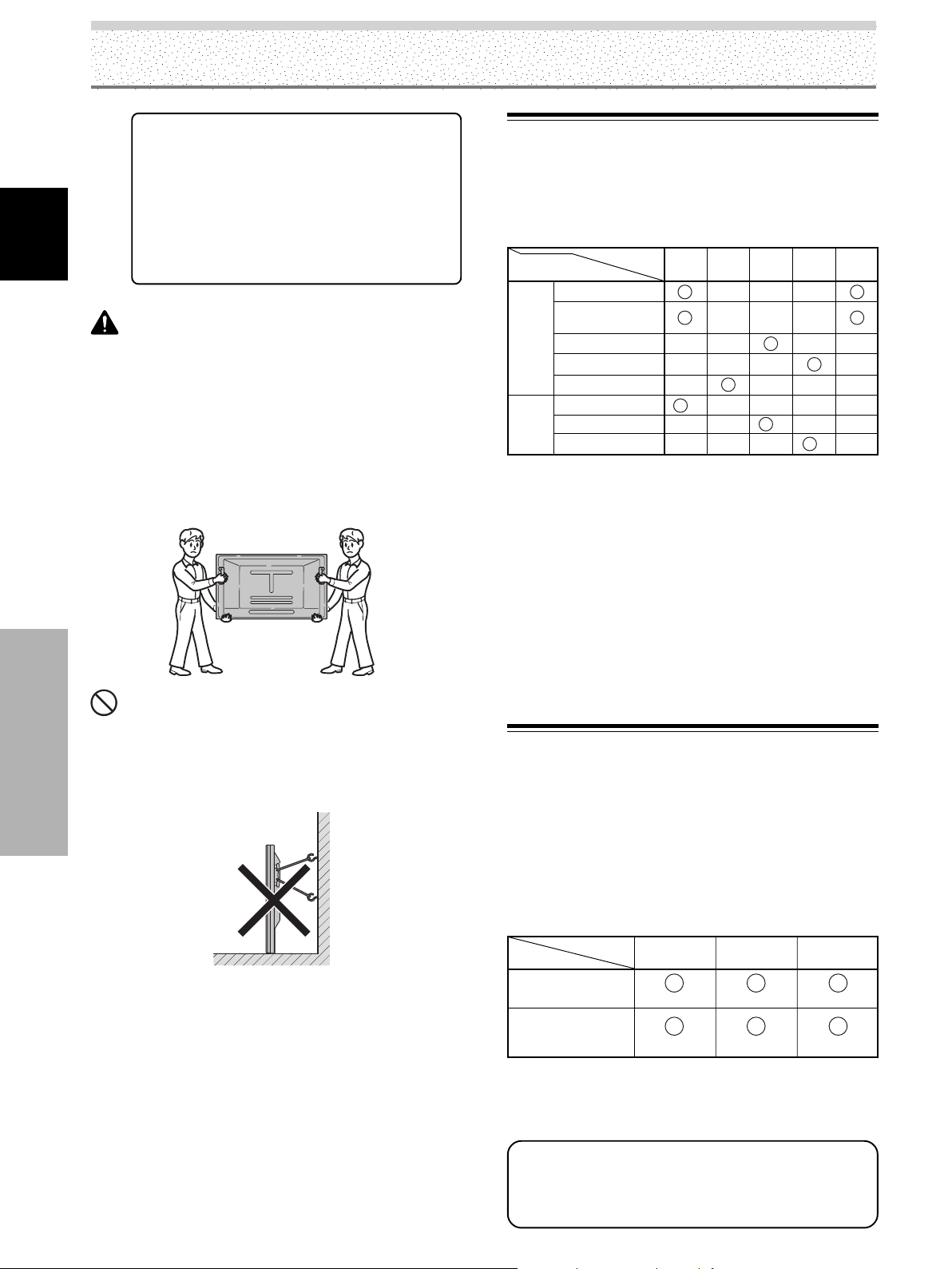
Installation et raccordements
7 Ligne en option (vendue séparément)
(Pour de plus amples détails, veuillez
consulter le revendeur qui vous a fourni
l’appareil.)
1 Support pour table : Support d’écran
2 Platine de fixation au mur: Elle est conçue pour
Français
PDP-5004 / PDP-5014 /
PDP-4304 / PDP-4314
assurer la liaison de
l’écran au mur et son
maintien.
AT TENTION
¶ Seul un technicien spécialisé en installation ou un personnel
de service sera habilité à détacher ou à rattacher les poignées.
¶ Si les poignées doivent être déposées en raison des
conditions particulières d’une installation, les vis de fixation
seront rangées soigneusement avec les poignées. Pour
garantir la sécurité, les vis de fixation seront serrées à un
couple minimum de 2 N·m (20 kgf·cm) lors de la remise en
place des poignées.
¶ Lors du déplacement de l’écran, il doit toujours être transporté
par deux personnes, saisissant les poignées arrière comme
illustré ici.
NON !
¶ N’essayez jamais de déplacer l’écran à plasma en ne le tenant
que par une de ses poignées.
¶ Lors de l’installation de l’écran à plasma, n’utilisez pas ses
poignées pour le suspendre à une paroi ni comme moyen
d’éviter qu’il ne bascule (voir l’illustration).
Installation et raccordements
Quelques mots sur les prises
d’entrée de l’appareil
Consultez le tableau qui suit avant d’effectuer les
raccordements à l’écran à plasma (pages 13 à 20).
Appareil et
signaux concernés
Appareil
audiovisuel
(PC)
Ordinateur
personnel
*1 Bien que les entrées INPUT1/INPUT5 soient compatibles
avec divers signaux, un paramétrage au moyen des menus
affichées est nécessaire après avoir effectué une liaison à
l’aide de ces prises de manière à prendre en compte les
caractéristiques de la source (pages 22 à 24).
*2 L’entrée INPUT1 est compatible avec Plug & Play (VESA DDC
1/2B) de Microsoft.
*3 Ce type de raccordement peut être impossible en raison de
la nature de la carte de sortie vidéo de l’ordinateur.
*4 Vu que l’entrée INPUT2 est compatible avec divers signaux,
un paramétrage au moyen d’un menu affiché est nécessaire
une fois que les liaisons sont faites; ceci afin de prendre en
compte les caractéristiques de l’appareil qui y est raccordé
(pages 25 à 26).
Prise d’entrée
RVB analogique
Composante
vidéo
S-vidéo
Vidéo composite
Vidéo numérique
RVB analogique
S-vidéo
Vidéo composite
INPUT
*1
1
*2
INPUT
*4
2
INPUT
3
*3
INPUT
4
*3
INPUT
*1
5
Raccordement aux entrées INPUT1
et INPUT5
Divers appareils peuvent être reliés aux prises d’entrée
INPUT1 et INPUT5. Une fois les raccordements achevés,
un paramétrage faisant appel aux menus affichés est
requis pour s’accommoder des caractéristiques de
l’appareil concerné. Veuillez vous reporter aux pages 22 à
24 pour tout ce qui relève du paramétrage après
raccordement.
Sortie
Prise INPUT5
Appareil vidéo dotés
d’une sortie RVB
Appareil vidéo doté
d’une sortie des
composantes vidéo
[ON SYNC]
Y
G ON SYNC
YCB/PB CR/PR
CB/PB CR/PR
B
R
12
FR
Remarque
Pour réaliser les raccordements à l’entrée INPUT1,
veuillez vous reporter à l’annexe 3, page 51.
Pour connaître la compatibilité des entrées INPUT1 et
INPUT5 en matière de formats d’image et de signaux
d’entrée, veuillez vous reporter à l’annexe 1 (page 48)
et à l’annexe 2 (pages 49 et 50).
Page 67
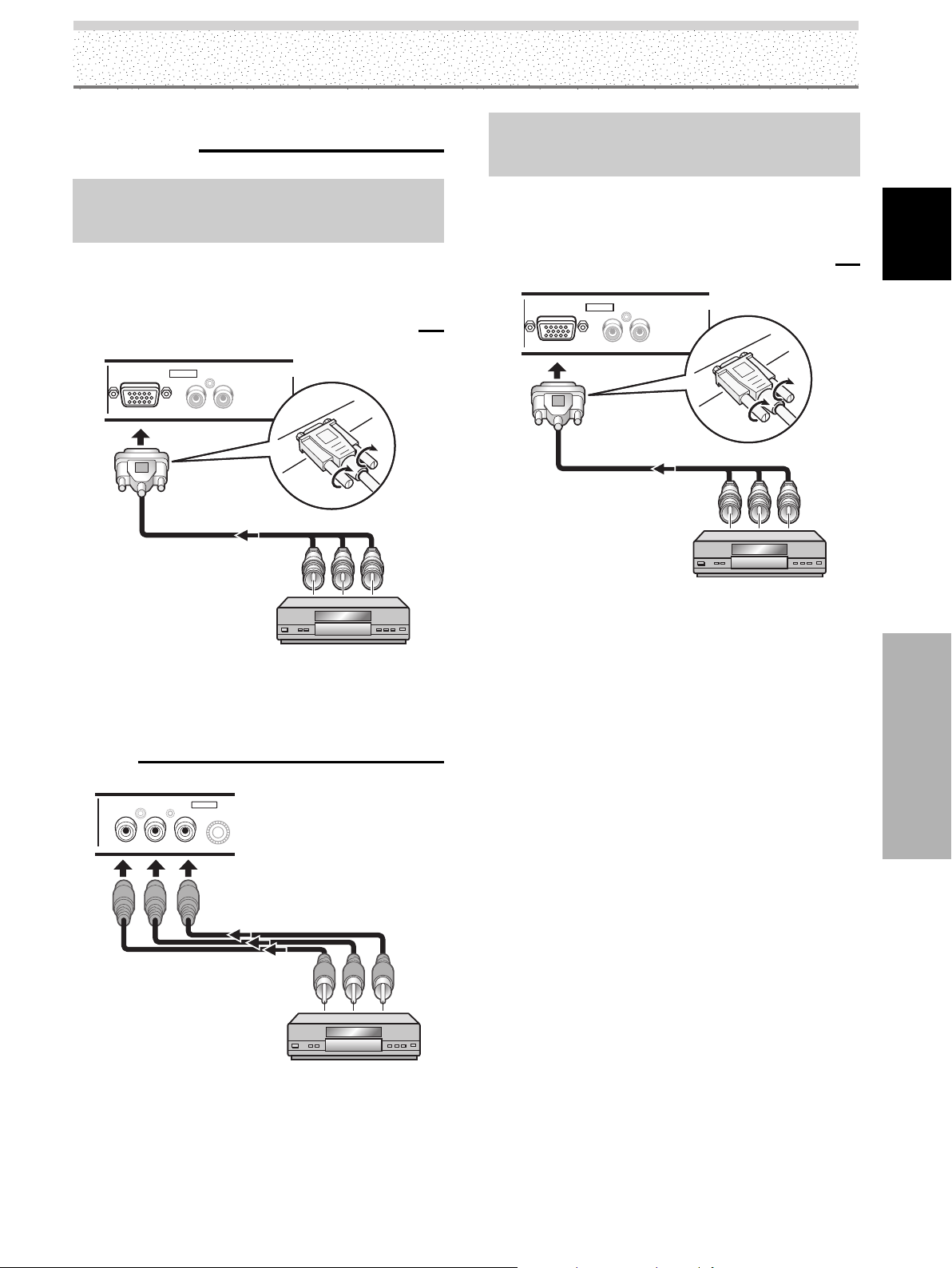
Installation et raccordements
Raccordement à un appareil
audiovisuel
Raccordement à un appareil audiovisuel
équipé de prises de sortie pour les
composantes vidéo
Si l’appareil audiovisuel est équipé de prises de sortie des
composantes vidéo, effectuez le raccordement vidéo par
le truchement de ces prises.
Cas du raccordement à ANALOG RGB IN (INPUT1)
ANALOG RGB IN
D-Sub
INPUT1
INPUT1
RL
AUDIO
Raccordement d’une source analogique RVB
fournissant un signal de synchronisation sur le
vert (G ON SYNC)
Effectuez une liaison G ON SYNC dans le cas d’un
appareil dont le signal de sortie contient le signal de
synchronisation en plus du signal pour le vert.
Cas du raccordement à ANALOG RGB IN (INPUT1)
ANALOG RGB IN
D-Sub
INPUT1
INPUT1
AUDIO
RL
Français
Ce raccordement étant terminé, un paramétrage faisant
appel aux menus affichés, est nécessaire.
Veuillez vous reporter aux pages 22 à 24.
Cas du raccordement à COMPOSANTES VIDÉO
(INPUT5)
COMPONENT
VIDEO
YCB/PB CR/PR
INPUT5
Ce raccordement étant terminé, un paramétrage faisant
appel aux menus affichés, est nécessaire.
Veuillez vous reporter aux pages 22 à 24.
Installation et raccordements
Appliquez le signal Y sur la prise Y, le signal CB/PB sur la
prise C
B/PB et le signal CR/PR sur la prise CR/PR.
Remarque
Cet appareil a été conçu pour fonctionner à partir de
composantes vidéo et de signaux de synchronisation présentant
un niveau stable et standard. En conséquence, des perturbations
peuvent apparaître au niveau de l’image en présence de signaux
de lecture inusités associés aux composantes vidéo.
13
FR
Page 68

Installation et raccordements
Cas du raccordement à COMPOSANTES VIDÉO
(INPUT5)
COMPONENT
VIDEO
YCB/PBCR/P
INPUT5
R
Français
Appliquez le signal G ON SYNC sur la prise Y, le signal B
sur la prise C
B/PB et le signal R sur la prise CR/PR.
Ce raccordement étant terminé, un paramétrage faisant
appel aux menus affichés, est nécessaire.
Veuillez vous reporter aux pages 22 à 24.
Raccordement à un ordinateur
personnel
La manière d’effectuer le raccordement dépend du type
de l’ordinateur. Avant de réaliser les raccordements, lisez
attentivement le mode d’emploi de l’ordinateur.
Prenez soin de vous assurer que l’ordinateur personnel et
son écran sont hors tension avant d’effectuer quelque
branchement que ce soit.
Pour connaître la compatibilité de cet appareil en matière
de formats d’image et de signaux d’entrée, veuillez vous
reporter au présent mode d’emploi.
Cas du raccordement à ANALOG RGB IN (INPUT1)
ANALOG RGB IN
D-Sub
INPUT1
INPUT1
AUDIO
RL
Raccordement d’une source analogique RVB
fournissant des signaux composites de
synchronisation
Effectuez une liaison pour synchronisation composite
dans le cas d’un appareil dont le signal de sortie contient
le signal de synchronisation verticale en plus du signal de
synchronisation horizontale.
Cas du raccordement à ANALOG RGB IN (INPUT1)
ANALOG RGB IN
D-Sub
Installation et raccordements
INPUT1
INPUT1
RL
AUDIO
Reliez le câble muni de la prise convenable côté entrée
sur l’écran à plasma et côté sortie sur l’ordinateur.
Assurez le maintien de ces prises en serrant les vis
prévues à cet effet.
Ce raccordement étant terminé, un paramétrage faisant
appel aux menus affichés, est nécessaire. Veuillez vous
reporter aux pages 22 à 24.
Remarque
En fonction du type de l’ordinateur, un adaptateur, etc., fourni
avec l’ordinateur ou vendu séparément, peut être nécessaire
pour réaliser la liaison.
Pour de plus amples détails concernant cette question, veuillez
vous reporter au mode d’emploi qui accompagne l’ordinateur, ou
consulter un revendeur.
Ce raccordement étant terminé, un paramétrage faisant
appel aux menus affichés, est nécessaire.
Veuillez vous reporter aux pages 22 à 24.
14
FR
Page 69

Installation et raccordements
Raccordement à INPUT2
Utilisez cette entrée pour un appareil audiovisuel dont la
sortie vidéo est numérique (décodeur, lecteur de DVD,
etc.) et compatible HDCP (High-bandwidth Digital Content
Protection). Avant de relier un appareil de ce type, lisez le
mode d’emploi qui l’accompagne afin de vous assurer
que la liaison peut être réalisée sans risque.
AUDIO
INPUT2
RL
Ce raccordement étant terminé, un paramétrage faisant
appel aux menus affichés, est nécessaire pour tenir
compte de l’appareil relié. Veuillez vous reporter aux
pages 25 à 26.
Remarques
¶ Utilisez un câble HDMI (High Definition Multimedia Interface)
pour réaliser la liaison.
¶ Si l’appareil possède une prise DVI, utilisez un câble
convertisseur DVI-HDMI pour réaliser la liaison.
¶ Cette prise n’est pas prévue pour être utilisée avec un
ordinateur personnel.
¶ Reportez-vous à l’annexe 1 (page 48) pour de plus amples
détails concernant les signaux et les formats d’image qui sont
pris en compte par ENTRÉE2.
HDMI
Appareil audiovisuel
possédant une sortie
vidéo numérique
Raccordement à INPUT3
Utilisez cette prise pour relier à la prise S-VIDEO
(INPUT3), un appareil audiovisuel possédant une prise de
sortie S-vidéo.
INPUT3
S-VIDEO
Appareil audiovisuel
Raccordement à INPUT4
Utilisez cette prise pour relier à la prise INPUT4, un
appareil audiovisuel possédant une sortie vidéo. La prise
VIDEO OUT (INPUT4) peut être utilisé pour appliquer le
signal vidéo de sortie à un moniteur extérieur, à un
appareil d’enregistrement et à tout autre appareil
possédant une entrée vidéo.
Remarque
Le signal vidéo n’est pas présent sur la prise VIDEO OUT
(INPUT4) lorsque l’écran est hors service ou en veille.
VIDEO
IN OUT
INPUT4
Français
Installation et raccordements
HDMI, le logo HDMI et High-Definition Multimedia Interface sont
des marques de commerce, déposées ou non, par HDMI Licensing
LLC.
Vers un moniteur ou un
dispositif
d’enregistrement
Appareil audiovisuel
15
FR
Page 70
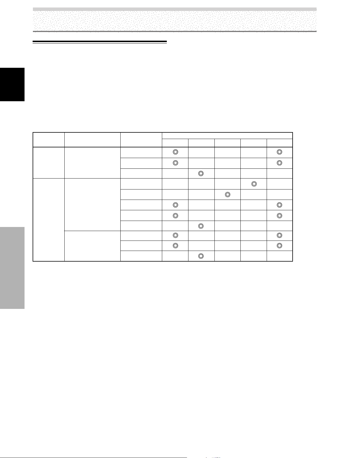
Installation et raccordements
Quelques mots sur le raccordement
d’un téléviseur numérique ou d’un
décodeur
Pour être assuré de réaliser les raccordements requis,
Français
lisez attentivement le mode d’emploi qui accompagne le
téléviseur numérique et le décodeur.
Les signaux de sortie du décodeur compatibles avec cet
écran figurent dans le tableau qui suit.
Type de
signal vidéo
HDTV
SDTV
Installation et raccordements
1080i (1125i)
720p (750p)
480i (525i)
480p (525p)
Signal vidéo
Format du signal
vidéo
Composantes
RVB
Numérique
Vidéo composite
S-vidéo
Composantes
RVB
Numérique
Composantes
RVB
Numérique
Prises qui peuvent être utilisées
INPUT1 INPUT4INPUT3INPUT2
INPUT5
16
FR
Page 71
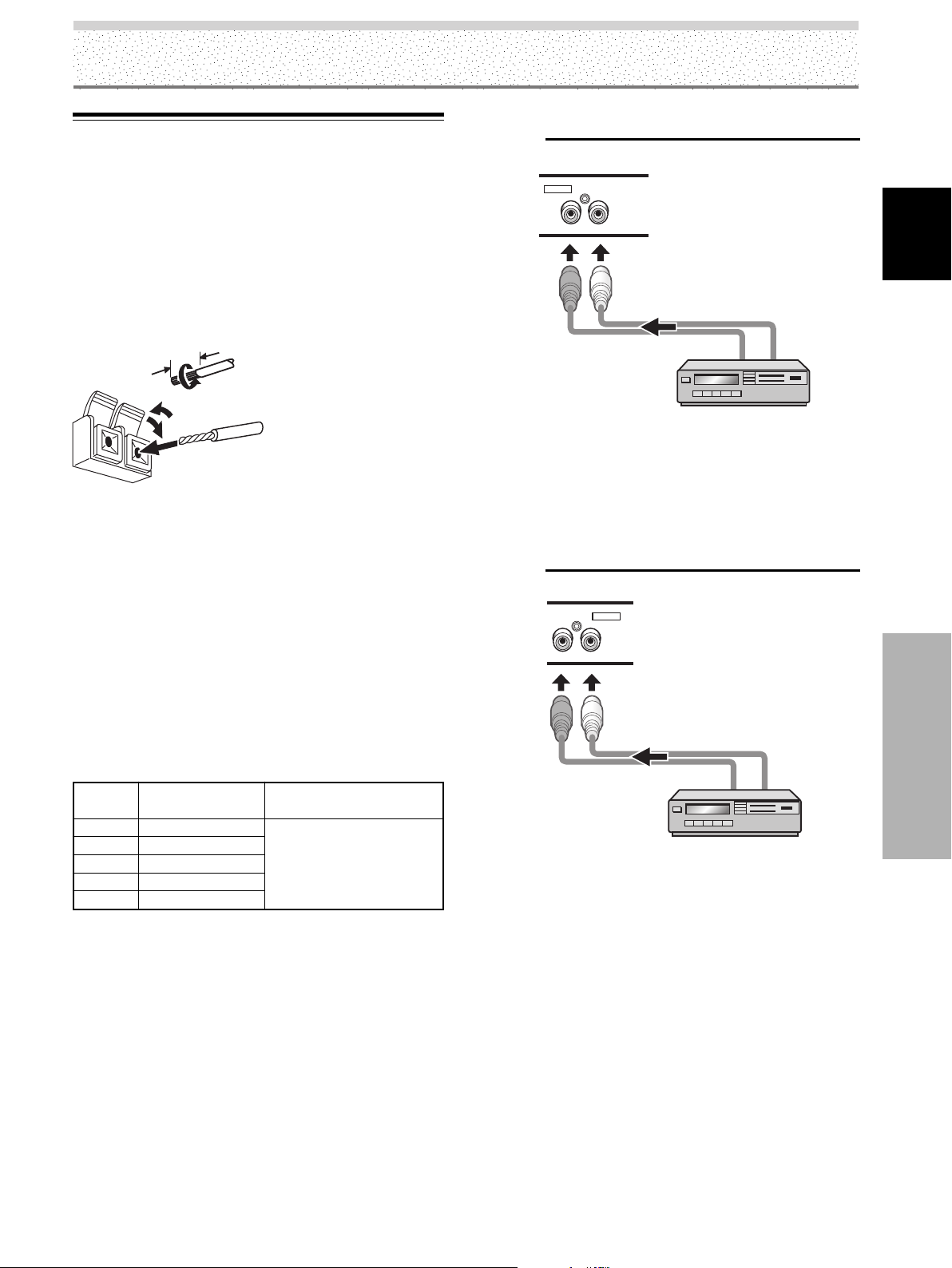
Raccordements audio
Installation et raccordements
Raccordement audio pour l’appareil relié à
INPUT1
Prenez soin de vous assurer que l’appareil audio et l’écran
sont hors tension avant d’effectuer quelque branchement
que ce soit.
Raccordement des enceintes
Cet appareil est pourvu d’un amplificateur intégré de 7 W
+ 7 W. Si des enceintes doivent être reliées, prenez
connaissance des instructions qui suivent.
12 mm
Remarques
¶ Après cette opération, exercez une traction légère sur le câble
pour vous assurer que le conducteur est bien prisonnier de la
prise. Dans le cas contraire, du bruit pourrait être produit, ou
les sons pourraient être interrompus.
¶ Veillez à ce que le conducteur du câble d’enceinte ª ou · ne
dépasse pas trop de la borne afin qu’il ne puisse pas venir en
contact avec le conducteur de l’autre câble et créer ainsi un
court-circuit. Cette situation entraînerait une charge excessive
de l’écran à plasma qui pourrait provoquer une anomalie de
fonctionnement, ou un arrêt de fonctionnement.
Torsadez les
brins mis à nu.
Poussez sur la languette
pour ouvrir la prise et
introduisez le conducteur.
Fermez ensuite la prise en
replaçant la languette dans
sa position d’origine.
AUDIO
INPUT1
INPUT1
RL
La ligne audio de l’appareil raccordé à INPUT1 peut être
raccordée aux fiches Cinch (RCA) AUDIO R/L (INPUT1).
Les sons sont appliqués sur les prises SPEAKER (L/R) en
fonction de la source vidéo sélectionnée.
Raccordement audio pour l’appareil relié à
INPUT2
AUDIO
INPUT2
RL
Français
Raccordement aux entrées audio de cet appareil
Cet appareil est équipé de 5 entrées audio. Le tableau qui
suit donne la liste des entrées vidéo et des entrées audio
qui leur correspondent.
Entrée
vidéo
INPUT1
INPUT2
INPUT3
INPUT4
INPUT5
Prises d’entrée
audio
Fiches (G/D)
Fiches (G/D)
Fiches (G/D)
Fiches (G/D)
Fiches (G/D)
Sortie son
Les sons provenant de
l’appareil vidéo sélectionné
sont présents en sortie sur
les prises SPEAKER (L/R).
Installation et raccordements
La liaison audio pour l’appareil relié à l’entrée INPUT2,
peut être réalisée par le truchement des prises AUDIO R/
L (INPUT2).
Les sons sont appliqués sur les prises SPEAKER (L/R) en
fonction de la source vidéo sélectionnée.
Remarque
Si vous utilisez les signaux AUDIO INPUT2, donnez à AUDIO la
valeur ANALOG (ou AUTO) (Veuillez vous reporter à la page 26).
17
FR
Page 72
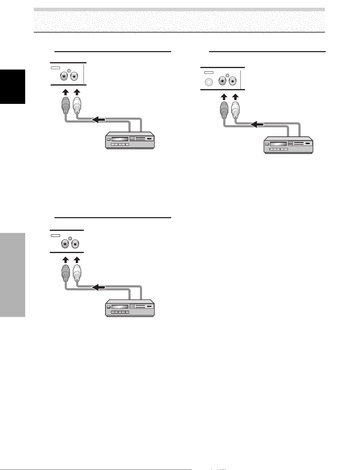
Installation et raccordements
Raccordement audio pour l’appareil relié à
INPUT3
INPUT3
AUDIO
RL
Français
La liaison audio pour l’appareil relié à l’entrée INPUT3,
peut être réalisée par le truchement des prises AUDIO R/
L (INPUT3).
Les sons sont appliqués sur les prises SPEAKER (L/R) en
fonction de la source vidéo sélectionnée.
Raccordement audio pour l’appareil relié à
INPUT4
Raccordement audio pour l’appareil relié à
INPUT5
INPUT5
AUDIO
RL
La liaison audio pour l’appareil relié à l’entrée INPUT5,
peut être réalisée par le truchement des prises AUDIO R/
L (INPUT5).
Les sons sont appliqués sur les prises SPEAKER (L/R) en
fonction de la source vidéo sélectionnée.
INPUT4
AUDIO
RL
Installation et raccordements
La liaison audio pour l’appareil relié à l’entrée INPUT4,
peut être réalisée par le truchement des prises AUDIO R/
L (INPUT4).
Les sons sont appliqués sur les prises SPEAKER (L/R) en
fonction de la source vidéo sélectionnée.
18
FR
Page 73

Raccordement du cordon
d’alimentation
Ne branchez le cordon d’alimentation qu’après avoir
réalisé tous les autres raccordements.
1 Reliez le cordon d’alimentation à cet appareil.
Installation et raccordements
Français
2 Branchez la fiche du cordon d’alimentation sur une
prise secteur.
AT TENTION
¶ N’utilisez que le cordon d’alimentation fourni.
¶ Par souci de sécurité, le système d’écran plasma est doté d’un
cordon d’alimentation à 3 conducteurs. Veillez à brancher la
fiche du cordon d’alimentation sur une prise secteur à 3
broches convenablement reliée à la terre. Si vous utilisez un
adaptateur, assurez-vous qu’il est muni d’une borne de masse
et reliez celle-ci à la terre.
NON!
¶ N’alimentez pas l’appareil sous une tension autre que celle
indiquée (120 V CA, 60 Hz) car vous pourriez provoquer un
incendie ou vous exposer à une secousse électrique.
Installation et raccordements
19
FR
Page 74

Installation et raccordements
Comment faire cheminer les câbles
Des colliers rapides et des colliers à œil sont fournis avec
l’écran à plasma pour permettre la mise en faisceau des
câbles. Après avoir relié les appareils, procédez comme il
est dit ci-dessous pour faire cheminer les câbles.
Français
L’illustration représente les modèles PDP-5004, PDP-5014,
PDP-4304 et PDP-4314.
2
1
*Vue de l’arrière.
1 Formez un faisceau de l’ensemble des câbles au
moyen des colliers rapides fournis.
Introduisez la partie 1 dans le perçage convenable, à
l’arrière de l’écran plasma, puis engagez la partie 2
dans la partie 1 pour assurer la fermeture du collier.
Les colliers rapides sont conçus pour être difficiles à
déposer une fois qu’ils sont en place et fermés.
Effectuez leur pose avec soin.
Fixation des colliers rapides à l’écran
Installation et raccordements
Fixez les colliers rapides dans les 6 perçages repérés par
‡ sur l’illustration ci-dessous; cela, en fonction du
cheminement prévu pour les câbles.
2 Formez des faisceaux de câbles au moyen des
colliers à œil fournis.
Veillez à ce qu’aucune traction excessive ne soit
exercée sur les câbles.
Remarque
Les câbles peuvent cheminer vers la gauche ou vers la droite.
L’illustration représente les modèles PDP-5004 et PDP-
5014.
*Vue de l’arrière.
Pour déposer les colliers rapides
Utilisez une paire de pinces pour tourner le collier de 90°
puis tirez-le vers l’extérieur.
Le collier peut se détériorer avec le temps, et être
endommagé au cours de sa dépose.
20
FR
Page 75
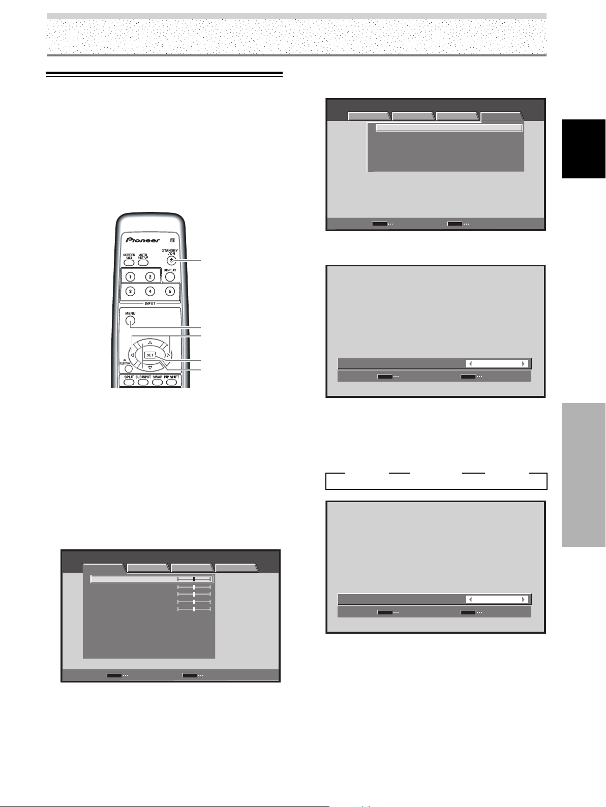
Mise en œuvre de l’ensemble
Sélection de la langue d’affichage
sur l’écran
Par défaut, la langue d’affichage sur l’écran est l’anglais.
Pour sélectionner une autre langue, un réglage est
nécessaire. Pour cela, procédez de la manière indiquée cidessous.
Pour les explications des réglages et de l’utilisation,
toutes les illustrations de la télécommande sont pour
PDP-5004/PDP-4304.
4 Utilisez les touches 2/3 pour sélectionner
[OPTION].
STANDARD INPUT1
PICTURE SCREEN SETUP OPTION
LANGUAGE ENGLISH
ENERGY SAVE
POWER MANAGEMENT:OFF
AUTO POWER OFF DISABLE
ORBITER OFF
MASK CONTROL ON
:
STANDARD
:
:
:
:
Français
STANDBY/
ON
MENU
2/3
SET
5/∞
Boîtier de télécommande
1 Placez l’interrupteur MAIN POWER du panneau
arrière sur la position ON.
Le témoin STANDBY de la face avant, s’éclaire
(couleur rouge).
2 Appuyez sur la touche STANDBY/ON pour mettre
l’écran en service.
Le témoin ON de la face avant, s’éclaire (couleur
verte).
3 Appuyez sur la touche MENU pour afficher la page
de menu.
STANDARD INPUT1
PICTURE SCREEN SETUP OPTION
CONTRAST
BRIGHTNESS
COLOR
TINT
SHARPNESS
MPEG NR
DNR
CTI
COLOR TEMP. MID
PICTURE RESET
SET
ENTER
:
:
:
:
:
:
:
:
:
0
0
0
0
0
ON
MID
ON
MENU
EXIT
SET
ENTER
MENU
EXIT
5 Utilisez les touches 5/∞ pour sélectionner
[LANGUAGE], puis appuyez sur la touche SET.
LANGUAGE
SET
SET
:
MENU
ENGLISH
EXIT
6 Utilisez les touches 2/3 pour sélectionner la
langue désirée.
Chaque pression sur une des touches 2/3 permet de
passer d’une valeur possible à une autre, dans l’ordre
suivant:
3
ENGLISH
LANGUAGE
2 3
SET
SET
FRANÇAIS
2 3
:
MENU
ESPAÑOL
FRANÇAIS
EXIT
2
7 Le nom de la langue désirée étant affiché, appuyez
sur la touche SET.
Le nom de la langue sélectionnée est mis en mémoire
puis la page affichée au cours de l’opération 4 est
rétablie.
8 Lorsque le réglage est achevé, appuyez sur la
touche MENU pour rétablir la page standard.
Remarque
Après avoir défini la langue pour une des entrées ENTRÉE 1 à
ENTRÉE 5, cette langue est utilisée quelle que soit la nature de
l’entrée considérée.
21
Mise en œuvre de l’ensemble
FR
Page 76

Mise en œuvre de l’ensemble
Réglages après raccordement
(INPUT1, 2, 5)
Après que les appareils ont été reliés à INPUT1, INPUT2
ou INPUT5, un paramétrage faisant appel aux menus
affichés est nécessaire. Procédez de la manière indiquée
Français
ci-dessous pour réaliser les réglages requis compte tenu
de la nature de l’appareil relié.
Paramétrage de [TYPE DE
SIGNAL] (INPUT1)/ [DÉCODAGE
COULEUR] (INPUT1, 5)
Remarques
¶ Ce paramétrage n’est requis (pour ENTRÉE1, que si les
signaux d’entrée appliqués présentent les taux de
rafraîchissement suivants: 1 31,5 kHz horizontalement / 60
Hz; 2 45 kHz horizontalement / 60 Hz verticalement; 3 48,4
kHz horizontalement / 60 Hz verticalement ou 56,1 kHz
horizontalement / 70 Hz verticalement. Pour les autres taux de
rafraîchissement, les réglages sont effectués
automatiquement et par conséquent toute intervention
manuelle est inutile (le paramétrage de [TYPE DE SIGNAL]
n’est pas possible).
¶ Le paramètre [DÉCODAGE COULEUR] n’est pas pris en
compte lorsque le signal d’entrée provient d’un ordinateur; il
en est de même lorsque la fonction [TYPE DE SIGNAL] a été
utilisée pour sélectionner un signal autre que [480p] ou [720p].
¶ Effectuez les paramétrages de [DÉCODAGE COULEUR]
séparément pour ENTRÉE1 ou ENTRÉE5.
¶ Le paramétrage de [TYPE DE SIGNAL] n’est possible que
lorsque ENTRÉE1 est sélectionnée.
2 Appuyez sur la touche MENU pour afficher la page
de menu.
STANDARD ENTRÉE1
IMAGE ÉCRAN SETUP OPTION
CONTRASTE
LUMINOSITÉ
COULEUR
TEINTE
NETTETÉ
MPEG NR
DNR
CTI
TEMP. COULEUR MOYEN
RÉINIT. IMAGE
SET
ENTRÉE
:
0
:
0
:
0
:
0
:
0
:
MARCHE
:
MOYEN
:
MARCHE
:
MENU
SORTIE
3 Utilisez les touches 2/3 pour sélectionner
[SETUP].
STANDARD ENTRÉE1
IMAGE ÉCRAN SETUP OPTION
PURECINEMA
POSITION CLAMP
TYPE DE SIGNAL
DÉCODAGE COULEUR
ENTRÉE HDMI
SET
ENTRÉE
:
ARRÊT
:
AUTO
:
480p
:
COMPOSANTE
MENU
SORTIE
4 Utilisez les touches 5/∞ pour sélectionner [TYPE
DE SIGNAL], puis appuyez sur la touche SET
(ENTRÉE1).
STANDARD ENTRÉE1
IMAGE ÉCRAN SETUP OPTION
PURECINEMA
POSITION CLAMP
TYPE DE SIGNAL
DÉCODAGE COULEUR
ENTRÉE HDMI
:
ARRÊT
:
AUTO
:
480p
:
COMPOSANTE
Mise en œuvre de l’ensemble
Boîtier de télécommande
1 Sélectionnez ENTRÉE1, ou ENTRÉE5.
22
FR
MENU
2/3
SET
5/∞
SET
ENTRÉE
MENU
SORTIE
5 Utilisez les touches 2/3 pour sélectionner le
mode d’affichage désiré.
TYPE DE SIGNAL
SET
VALIDER
:
MENU
480p
SORTIE
Page 77

Mise en œuvre de l’ensemble
1 Lorsque le signal d’entrée a un taux de
rafraîchissement de 31,5 kHz horizontalement/60
Hz verticalement, une pression sur les touches 2/
3 provoque un changement du mode d’affichage
conformément à ce qui suit:
3 480p 2
3 WVGA 2
3 VGA 2
2 Lorsque le signal d’entrée a un taux de
rafraîchissement de 45 kHz horizontalement/60 Hz
verticalement, une pression sur les touches 2/3
provoque un changement du mode d’affichage
conformément à ce qui suit:
3 720-PC 23 720p 2
[720-PC] indique que la définition est 1280 x 720.
3 Lorsque le signal d’entrée a un taux de
rafraîchissement de 48,4 kHz horizontalement/60
Hz verticalement, ou 56,1 kHz horizontalement/ 70
Hz verticalement, une pression sur les touches
2/3 provoque un changement du mode d’affichage
conformément à ce qui suit:
3 XGA 2 3 WXGA 2
3 PC AUTO. 2
Si le paramètre [PC AUTO.] est sélectionné, la
définition de l’image passe automatiquement de
[XGA] à [WXGA], et inversement, en fonction des
besoins.
Remarques
¶ Le paramètre [PC AUTO.] ne prend en compte la sélection
automatique du signal que si les entrées sont de type RVB à
synchronisation séparée.
¶ Avec des signaux d’entrée G ON SYNC ou à synchronisation
composite, la sélection de [PC AUTO.] provoque seulement la
sélection de [XGA] comme définition d’image.
¶ Avec des signaux d’entrée WXGA à G ON SYNC ou à
synchronisation composite, donnez manuellement à [TYPE DE
SIGNAL] la valeur [WXGA].
6 Appuyez sur la touche SET.
La valeur adoptée est mise en mémoire puis la page
affichée au cours de l’opération 4 est rétablie.
7 Lorsqu’un appareil autre qu’un ordinateur est relié,
utilisez les touches 5/∞ pour sélectionner
[DÉCODAGE COULEUR] puis appuyez sur la
touche SET (ENTRÉE1 ou ENTRÉE5).
STANDARD ENTRÉE1
IMAGE ÉCRAN SETUP OPTION
PURECINEMA
POSITION CLAMP
TYPE DE SIGNAL
DÉCODAGE COULEUR
ENTRÉE HDMI
:
ARRÊT
:
AUTO
:
480p
:
COMPOSANTE
8 Utilisez les touches 2/3 pour sélectionner la
nature du signal d’entrée.
COMPOSANTE
DÉCODAGE COULEUR
SET
VALIDER
:
MENU
SORTIE
Chaque pression sur les touches 2/3 buttons, modifie
le réglage, comme suit:
3 RVB 23 COMPOSANTE 2
Le tableau suivant donne les valeurs disponibles en
fonction du type de raccordement et celles qui
conviennent.
Adoptez pour [TYPE DE SIGNAL] et [DÉCODAGE
COULEUR] les valeurs proposées dans le tableau cidessous. Procédez avec soin car le choix d’une valeur
incorrecte peut avoir un résultat désastreux sur l’écran.
SETUP
Appareil
relié
Sortie des composantes
vidéo provenant d’un
lecteur de DVD, etc.
Sortie des composantes
vidéo provenant d’un
syntoniseur numérique,
etc.
Sortie vidéo RVB
provenant d’un
magnétoscope, etc.
équipé d’une sortie RVB
Sortie RVB provenant
d’un ordinateur personnel
TYPE DE
SIGNAL
480p
720p
480p
VGA, WVGA,
720-PC,
XGA, WXGA
DÉCODAGE
COULEUR
COMPOSANTE
COMPOSANTE
RVB
N’est pas pris en
compte
9 Appuyez sur la touche SET.
Le paramétrage de [DÉCODAGE COULEUR] est
terminé, et la page affichée au cours de l’opération 7
est rétablie.
10 Lorsque le paramétrage est terminé, appuyez sur
la touche MENU pour fermer la page de menu.
Français
Mise en œuvre de l’ensemble
SET
ENTRÉE
MENU
SORTIE
23
FR
Page 78

Mise en œuvre de l’ensemble
Paramétrage de [POSITION
CLAMP] (ENTRÉE1, 5)
En fonction de certains éléments, les signaux analogiques
RVB peuvent donner des images écran blanchâtre ou
verdâtre. Dans un tel cas, donnez à [POSITION CLAMP] la
valeur [VERROUILLÉ]. En principe, conservez la valeur
Français
[AUTO].
3
Utilisez les touches 5/∞ pour sélectionner
[POSITION CLAMP] puis appuyez sur la touche SET.
STANDARD ENTRÉE1
IMAGE ÉCRAN SETUP OPTION
PURECINEMA
POSITION CLAMP
TYPE DE SIGNAL
DÉCODAGE COULEUR
ENTRÉE HDMI
:
ARRÊT
:
AUTO
:
480p
:
RVB
Boîtier de télécommande
1
Appuyez sur la touche MENU pour afficher la page
de menu.
STANDARD ENTRÉE1
IMAGE ÉCRAN SETUP OPTION
CONTRASTE
LUMINOSITÉ
COULEUR
TEINTE
NETTETÉ
MPEG NR
DNR
CTI
TEMP. COULEUR MOYEN
RÉINIT. IMAGE
SET
ENTRÉE
:
0
:
0
:
0
:
0
:
0
:
MARCHE
:
MOYEN
:
MARCHE
:
MENU
2 Utilisez les touches 2/3 pour sélectionner
[SETUP].
Mise en œuvre de l’ensemble
STANDARD ENTRÉE1
IMAGE ÉCRAN SETUP OPTION
PURECINEMA
POSITION CLAMP
TYPE DE SIGNAL
DÉCODAGE COULEUR
ENTRÉE HDMI
SORTIE
:
ARRÊT
:
AUTO
:
480p
:
RVB
MENU
2/3
SET
5/∞
SET
ENTRÉE
MENU
SORTIE
4 Utilisez les touches 2/3 pour sélectionner
[VERROUILLÉ].
VERROUILLÉ
POSITION CLAMP
SET
VALIDER
:
MENU
SORTIE
La valeur par défaut est [AUTO].
Chaque pression sur les touches 2/3 buttons, modifie
le réglage, comme suit:
3 AUTO 2
3 VERROUILLÉ 2
5 Appuyez sur la touche SET.
Le paramétrage de [POSITION CLAMP] est terminé,
et la page affichée au cours de l’opération 3 est
rétablie.
6 Lorsque le paramétrage est terminé, appuyez sur
la touche MENU pour fermer la page de menu.
Remarques
¶ Le paramétrage de [POSITION CLAMP] n’est possible que
lorsque ENTRÉE1 ou ENTRÉE5 est sélectionnée.
¶ Lorsque vous effectuez ce paramétrage, soyez attentif au
signal de sortie de l’appareil que vous utilisez. Pour de plus
amples détails concernant cette question, reportez-vous au
mode d’emploi qui accompagne l’appareil en question.
24
FR
SET
ENTRÉE
MENU
SORTIE
Page 79

Mise en œuvre de l’ensemble
Paramétrage de HDMI (ENTRÉE2)
Effectuez ce paramétrage après avoir réalisé la liaison
HDMI à INPUT2.
Procédez de la manière indiquée ci-dessous pour réaliser
les réglages requis compte tenu de la nature de l’appareil
relié.
Remarque
Le paramétrage de HDMI n’est possible que lorsque ENTRÉE2
est sélectionnée.
SÉLECTION IMAGE
Cette fonction permet de sélectionner le format du signal
d’entrée, automatiquement ou manuellement, lorsque ce
signal est numérique.
1 Appuyez sur la touche MENU pour afficher la page
de menu.
STANDARD ENTRÉE2
IMAGE ÉCRAN SETUP OPTION
CONTRASTE
LUMINOSITÉ
COULEUR
TEINTE
NETTETÉ
MPEG NR
DNR
CTI
TEMP. COULEUR MOYEN
RÉINIT. IMAGE
SET
2 Utilisez les touches 2/3 pour sélectionner
[SETUP].
STANDARD ENTRÉE2
IMAGE ÉCRAN SETUP OPTION
PURECINEMA
POSITION CLAMP
TYPE DE SIGNAL
DÉCODAGE COULEUR
ENTRÉE HDMI
ENTRÉE
:
0
:
0
:
0
:
0
:
0
:
MARCHE
:
MOYEN
:
MARCHE
:
MENU
:
ARRÊT
:
:
:
SORTIE
4 Utilisez les touches 5/∞ pour sélectionner
[SÉLECTION D’IMAGE].
ENTRÉE HDMI
:
SÉLECTION D'IMAGE
AUDIO
SET
VALIDER
:
MENU
AUTO
AUTO
SORTIE
5 Utilisez les touches 2/3 pour sélectionner le
paramètre [SÉLECTION D’IMAGE].
Le réglage adopté en usine pour l’appareil est AUTO.
Chaque pression sur les touches 2/3, modifie le
réglage, comme suit:
3 AUTO 23 COULEUR1 2
3 COULEUR4 23 COULEUR3 23 COULEUR2 2
AUTO: Le type des signaux d’entrée vidéo est
automatiquement identifié.
COULEUR1: Les signaux Y C
acceptés.
COULEUR2: Les signaux Y C
acceptés.
COULEUR3: Sélectionnez COULEUR3 lorsque l’image
est très sombre ou déformée et que les
signaux RVB sont acceptés.
COULEUR4: Sélectionnez COULEUR4 pour effacer les
reflets blancs lorsque les RVB sont
acceptés.
Remarque
Même si la valeur AUTO a été sélectionnée, le choix automatique
peut ne pas se produire correctement pour certains signaux
d’entrée. Dans ce cas, sélectionnez manuellement COULEUR1,
COULEUR2, COULEUR3 ou COULEUR4 selon la nature exacte
du signal effectivement appliqué à l’entrée.
B/PB CR/PR (4 : 2 : 2) sont
B/PB CR/PR (4 : 4 : 4) sont
Français
Mise en œuvre de l’ensemble
SET
ENTRÉE
MENU
SORTIE
3 Utilisez les touches 5/∞ pour sélectionner
[ENTRÉE HDMI], puis appuyez sur la touche SET.
STANDARD ENTRÉE2
IMAGE ÉCRAN SETUP OPTION
PURECINEMA
POSITION CLAMP
TYPE DE SIGNAL
DÉCODAGE COULEUR
ENTRÉE HDMI
SET
ENTRÉE
:
ARRÊT
:
:
:
MENU
SORTIE
6 Appuyez sur la touche SET.
Le paramétrage de [SÉLECTION D’IMAGE] est
terminé, et la page affichée au cours de l’opération 3
est rétablie.
7 Lorsque le réglage est achevé, appuyez sur la
touche MENU pour rétablir la page standard.
25
FR
Page 80

Mise en œuvre de l’ensemble
AUDIO
Cette fonction permet de sélectionner le signal d’entrée
audio, automatiquement ou manuellement, lorsque ce
signal est numérique.
1 Appuyez sur la touche MENU pour afficher la page
de menu.
Français
2 Utilisez les touches 2/3 pour sélectionner
STANDARD ENTRÉE2
IMAGE ÉCRAN SETUP OPTION
CONTRASTE
LUMINOSITÉ
COULEUR
TEINTE
NETTETÉ
MPEG NR
DNR
CTI
TEMP. COULEUR MOYEN
RÉINIT. IMAGE
SET
ENTRÉE
:
0
:
0
:
0
:
0
:
0
:
MARCHE
:
MOYEN
:
MARCHE
:
MENU
[SETUP].
STANDARD ENTRÉE2
IMAGE ÉCRAN SETUP OPTION
PURECINEMA
POSITION CLAMP
TYPE DE SIGNAL
DÉCODAGE COULEUR
ENTRÉE HDMI
:
ARRÊT
:
:
:
SORTIE
5 Utilisez les touches 2/3 pour sélectionner le
paramètre [AUDIO].
Le réglage adopté en usine pour l’appareil est AUTO.
Chaque pression sur les touches 2/3, modifie le
réglage, comme suit:
3 AUTO 2
3 ANALOGIQUE 23 NUMÉRNIQUE2
AUTO: Le type des signaux d’entrée audio est
automatiquement identifié.
NUMÉRNIQUE: Les signaux audio numérniques sont
acceptés.
ANALOGIQUE: Les signaux audio analogiques sont
acceptés.
Remarque
Même si la valeur AUTO a été sélectionnée, le choix automatique
peut ne pas se produire correctement pour certains signaux
d’entrée. Dans ce cas, sélectionnez manuellement
NUMÉRNIQUE ou ANALOGIQUE selon la nature exacte du
signal effectivement appliqué à l’entrée.
6 Appuyez sur la touche SET.
Le paramétrage de [AUDIO] est terminé, et la page
affichée au cours de l’opération 3 est rétablie.
7 Ce paramétrage étant achevé, appuyez une
nouvelle fois sur la touche MENU pour rétablir la
page standard.
SET
ENTRÉE
MENU
3 Utilisez les touches 5/∞ pour sélectionner
[ENTRÉE HDMI], puis appuyez sur la touche SET.
STANDARD ENTRÉE2
IMAGE ÉCRAN SETUP OPTION
PURECINEMA
POSITION CLAMP
TYPE DE SIGNAL
DÉCODAGE COULEUR
ENTRÉE HDMI
:
ARRÊT
:
:
:
Mise en œuvre de l’ensemble
SET
ENTRÉE
MENU
4 Utilisez les touches 5/∞ pour sélectionner
[AUDIO].
ENTRÉE HDMI
SÉLECTION D'IMAGE
AUDIO
SET
VALIDER
:
:
MENU
SORTIE
SORTIE
AUTO
AUTO
SORTIE
26
FR
Page 81
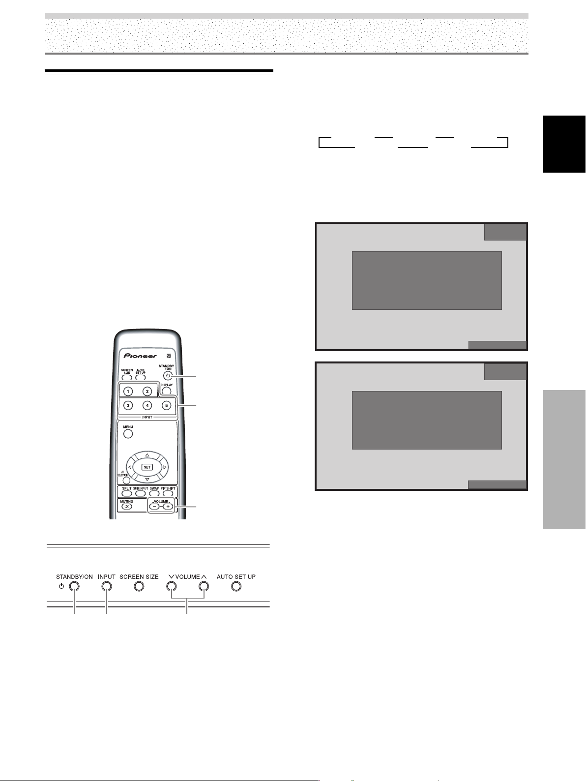
Fonctionnement
Choix de la source
Cette section explique le fonctionnement de base de
l’écran à plasma. Dans les pages qui suivent, figurent le
mode opératoire pour mettre l’écran sous tension ou hors
tension, pour mettre l’écran en service ou en veille et
pour sélectionner un des appareils qui lui sont reliés.
Avant de poursuivre, assurez-vous que:
¶ Les raccordements entre l’écran à plasma et les
appareils audiovisuels ou l’ordinateur personnel ont été
réalisées conformément à ce qui est dit dans la section
“Installation et raccordements” qui débute à la page 11.
¶ Le paramétrage à l’aide des menus affichés a été
réalisé pour les appareils reliés aux entrées INPUT1,
INPUT2 et INPUT5 conformément à ce qui a été dit à la
section “Mise en œuvre de l’ensemble” qui débute à la
page 21.
Si ces prises ne sont reliées à aucun appareil, la mise
œuvre à l’aide des menus affichés est inutile.
3 Appuyez sur la touche INPUT du boîtier de
télécommande ou de l’appareil pour sélectionner
l’entrée.
Chaque pression sur la touche INPUT de l’écran
change l’entrée sélectionnée, comme suit:
3 ENTRÉE1 3 ENTRÉE2 3 ENTRÉE3
ENTRÉE5 2 ENTRÉE4 2
¶ Lorsque la page de menu est affichée, tout
changement d’entrée provoque l’effacement de la
page de menu.
¶ Si le signal provenant de l’ordinateur n’est pas pris
en compte par l’écran, le message suivant s’affiche:
ATTENTION
SIGNAL NON RECONNU
:
86.7
:
88.5
D-SUB
kHz
HzfV
fH
1152x864
ENTRÉE1
STANDARD
Français
STANDBY/
ON
INPUT
VOLUME
[–/+]
Boîtier de télécommande
STANDBY/
ON
INPUT
Panneau de commande de l’écran à plasma
VOLUME [–/+]
1 Placez l’interrupteur MAIN POWER du panneau
arrière sur la position ON.
Le témoin STANDBY de la face avant, s’éclaire
(couleur rouge).
2 Appuyez sur la touche STANDBY/ON pour mettre
l’écran en service.
Le témoin ON de la face avant, s’éclaire (couleur
verte).
PLEIN ÉCRAN
ENTRÉE1
STANDARD
ATTENTION
FREQ. HORS STANDARD
:
75.7
:
120.0
D-SUB
kHz
HzfV
PLEIN ÉCRAN
fH
4 Utilisez les touches VOLUME (+/–) du boîtier de
télécommande ou de l’écran pour régler le niveau
sonore de sortie.
Si aucune liaison audio n’est réalisée avec l’écran à
plasma, cette opération n’est pas nécessaire.
5 Lorsque vous n’avez plus besoin de l’écran,
appuyez sur la touche STANDBY/ON pour le
mettre en veille.
6 Placez l’interrupteur MAIN POWER du panneau
arrière sur la position ARRÊT.
Le témoin STANDBY peut demeurer éclairé pendant
quelques instant après la mise hors service de
l’appareil. Cela tient à la charge électrique des circuits,
mais ce témoin finira par s’éteindre.
Remarque
Ne conservez pas la même image affichée sur l’écran pendant
une longue période. En effet, une image affichée pendant une
longue période peut provoquer un brûlage d’écran qui se traduit
par l’apparition d’une image fantôme ou résiduelle qui ne semble
pas vouloir disparaître.
27
Fonctionnement
FR
Page 82

Fonctionnement
Réglage du niveau d’écoute
Appuyez sur la touche MUTING du boîtier de
télécommande.
Appuyez une nouvelle fois sur la touche MUTING pour
rétablir les sons. Une pression sur la touche VOLUME +
rétablit aussi les sons.
Français
VOLUME
AXD1496
Boîtier de télécommande
VOLUME [–/+]
Panneau de commande de l’écran à plasma
[–/+]
Appuyez sur les touches VOLUME.
Appuyez sur la touche [–] ou sur la touche [+] pour
diminuer ou augmenter le niveau sonore émis par les
enceintes.
Fonctionnement
:
11VOLUME
Vérification des réglages actuels
DISPLAY
Boîtier de télécommande
Appuyez sur la touche DISPLAY.
L’entrée actuellement sélectionnée, la sélection AV, le
format d’image choisi et le taux de rafraîchissement
adopté sont affichés pendant environ 3 secondes.
ENTRÉE1
STANDARD
:
:
1024
X
768
D-SUB
k
448
HzfH .
HzfV .
060
Interruption des sons
AXD1496
28
FR
POINT PAR POINT
Remarque
La valeur affichée pour le taux de rafraîchissement peut être
légèrement différente de la valeur réelle.
MUTING
Page 83

Adoption du format d’image
Cet écran à plasma est en mesure d’afficher des images
ayant des hauteurs et des largeurs différentes. Nous vous
conseillons de choisir le format correspondant le mieux à
la source vidéo. Bien que ces modes aient été imaginés
pour l’affichage d’une image sur grand écran, nous
espérons que vous les emploierez en tenant compte des
intentions qui ont prévalu à leur choix.
Choix du format d’image
Le format de l’image affichée sur l’écran peut avoir 5
valeurs différentes dans le cas d’une source d’entrée
vidéo et 3 formats différents dans le cas d’un ordinateur
personnel.
SCREEN
SIZE
Boîtier de télécommande
SCREEN SIZE
Panneau de commande de l’écran à plasma
Fonctionnement
2 Appuyez une nouvelle fois sur la touche SCREEN
SIZE tandis que le format actuel de l’image est
indiqué à la partie inférieure droite de l’écran.
Le réglage change comme suit:
Dans le cas où le signal d’entrée provient d’un appareil vidéo
(ENTRÉE1 à 5)
Avec ENTRÉE1, 2 et 5, les formats d’image
sélectionnables diffèrent en fonction du signal d’entrée.
Pour plus de détails, veuillez vous reporter au tableau de
la page 48, “Signaux vidéo pris en compte”.
3 LARGE 3 4:3 3 PLEIN ÉCRAN
CINÉMA 2 ZOOM 2
Dans le cas où le signal d’entrée provient d’un ordinateur
personnel (ENTRÉE1)
3 POINT PAR POINT 3 4:3
PLEIN ÉCRAN 2
Le format d’image que vous pouvez sélectionner dépend
de la nature du signal d’entrée. Pour de plus amples
détails concernant cette question, veuillez vous reporter
au tableau de la page 48, “Signaux vidéo pris en compte”
ou à celui de la page 49 à 50, “Signaux ordinateur pris en
compte”.
Remarques
¶ Lorsque les valeurs [LARGE], [ZOOM] ou [PLEIN ÉCRAN] sont
adoptées pour afficher une image 4/3 sur la totalité d’un écran
large, une portion de l’image peut être tronquée ou déformée.
¶ Sachez que si vous utilisez l’écran dans un dessein commercial
ou public, l’adoption des valeurs [LARGE], [ZOOM], [CINÉMA]
or [PLEIN ÉCRAN] peut enfreindre les droits d’auteur tels
qu’ils sont protégés par les lois en vigueur dans ce domaine.
¶ Quand le format d’image [POINT PAR POINT] (sauf avec les
PDP-5004/PDP-5014 à 1280 x 768 ou les PDP-4304/PDP-4314
à 1024 x 768) ou [4:3] est sélectionné, et lorsque CONTRÔLE
MASQUE est en service (page 42), la position d’affichage est
légèrement déplacée à chaque mise sous tension de manière
à éviter le brûlage.
Français
Fonctionnement
1 Appuyez sur la touche SCREEN SIZE.
Le format actuel de l’image est affiché à la partie
inférieure droite de l’écran.
PLEIN ÉCRAN
29
FR
Page 84

Fonctionnement
Dans le cas où le signal d’entrée provient d’un
appareil vidéo
Comment se présente l’image
LARGE
Français
4:3
PLEIN ÉCRAN
ZOOM
CINÉMA
Pour les informations et les
reportages sportifs. Les films et
les reportages sportifs donnent
lieu à des images puissantes.
Pour les informations et les
comédies de situation. Le format
d’un document vidéo n’est pas
modifié.
Pour les images grand format
(tassement).
Pour les films en Cinémascope et
autres techniques voisines.
L’image est vaste et puissante.
Spécialement adapté aux formats
VistaVision.
[PDP-4304, PDP-4314]
* Le PDP-4304 et PDP-4314 sont réalisé avec des
éléments horizontaux oblongs, ce qui se traduit par
une image affichée plus oblongue que l’image
originale que contient le signal d’entrée.
480 lignes
A
640 points
1024 points
(L’illustration montre le cas d’une entrée 640 x 480.)
2 4:3
L’image remplit l’écran autant qu’il est possible, sans pour
autant que le format de l’image originale que contient le
signal d’entrée soit modifié.
768 lignes
1 POINT PAR POINT
Le signal d’entrée et l’écran maintiennent un rapport point
à ligne de 1/1, ce qui assure une remarquable fidélité visà-vis de la source.
[PDP-5004, PDP-5014]
Fonctionnement
480 lignes
A
640 points
1280 points
(L’illustration montre le cas d’une entrée 640 x 480.)
A
3 PLEIN ÉCRAN
L’image est présentée au format 16/9, le format d’un
grand écran, et occupe tout l’écran.
A
768 lignes
Remarque
Si la même image au format 4/3 demeure sur l’écran pendant
plusieurs heures, ou encore apparaît tous les jours de manière
répétée, une image rémanente peut être produite par brûlage.
Pour éviter ce phénomène de brûlage, utilisez un format différent
du format 4/3 chaque fois que cela est possible et que cela ne
vous conduit pas à enfreindre les droits d’auteur.
30
FR
Page 85

Affichage de plusieurs images
[PDP-5004, PDP-4304 seulement]
L’écran à plasma est conçu pour permettre l’affichage
simultané des images de deux entrées. L’affichage de
plusieurs images peut avoir lieu selon 3 modes: 2-ÉCRAN
(2 images), PinP (image dans l’image) et PoutP (image
hors de l’image).
Fonctionnement
2 PinP
L’image secondaire et affichée dans un des 4 coins de
l’image principale.
ENTRÉE1
Français
DISPLAY
SPLIT
SUB INPUT
AXD1496
PIP SHIFT
SWAP
1 Appuyez sur la touche SPLIT du boîtier de
télécommande.
Chaque pression sur cette touche change le mode de
fonctionnement, comme suit:
3 2-SCREEN 3 PinP 3 PoutP 3 ARRÊT
1 2-SCREEN
L’image principale apparaît sur la gauche et l’image
secondaire sur la droite.
ENTRÉE2
3 PoutP
L’image secondaire est affichée en dehors de l’image
principale et sur sa droite.
ENTRÉE1
ENTRÉE2
2 Appuyez sur la touche SUB INPUT du boîtier de
télécommande pour sélectionner la source de
l’image secondaire.
Pour permuter les entrées d’image principale et
d’image secondaire:
Appuyez sur la touche SWAP du boîtier de
télécommande.
ENTRÉE2ENTRÉE1
¶ Lorsque le mode 2-ÉCRAN est sélectionné:
Les images de gauche et de droite permutent; l’image
principale devient l’image secondaire, et vice versa.
¶ Lorsque le mode PinP, ou PoutP, a été sélectionné:
La taille de l’image principale est réduite et elle devient
l’image secondaire, et vice versa.
Fonctionnement
Pour changer la position de l’image secondaire
quand le mode PinP est adopté:
Appuyez sur la touche PIP SHIFT du boîtier de
télécommande.
Chaque pression sur cette touche change la position de
l’image secondaire, comme suit:
3 Coin inférieur droit 3 Coin supérieur droit
Coin inférieur gauche 2 Coin supérieur gauche 2
31
FR
Page 86

Fonctionnement
Pour afficher l’image de l’entrée actuellement
sélectionnée:
Appuyez sur la touche DISPLAY.
Si vous appuyez sur la touche DISPLAY alors que l’écran
peut afficher plusieurs images, l’image principale et
l’image secondaire de chaque entrée sélectionnée,
s’affichent.
Français
Remarques
¶ Lorsque l’écran à plasma est utilisé pour afficher des images
dans un contexte lucratif ou public, l’emploi de la fonction de
sélection du format d’image pour rétrécir ou agrandir les
images, peut enfreindre les droits d’auteur.
¶ Si les mêmes images demeurent sur l’écran pendant une
longue période, ou encore apparaissent tous les jours de
manière répétée, une image rémanente peut être produite par
brûlage.
¶ Après avoir sélectionné le mode 2-ÉCRAN et en fonction de la
source, l’image peut sembler un peu grossière.
¶ L’affichage de plusieurs images est abandonné lorsqu’un menu
est ouvert.
¶ Le format de l’image ne peut pas être modifié lorsque
plusieurs images sont affichées.
¶ Les sons émis quand plusieurs images sont affichées, sont les
sons provenant de la source donnant l’image principale.
¶ Étant donné que les circuits utilisés pour l’image principale
donnent une meilleure qualité que ceux utilisés pour l’image
secondaire, la qualité d’affichage de ces images diffère.
¶ Lorsqu’on effectue le réglage de qualité d’image, certains
éléments n’affectent pas la qualité de l’image secondaire.
Paramétrage de AV SELECTION
Pour bénéficier de la meilleure image possible, vous avez
le choix entre 5 jeux de réglages dans le cas d’une entrée
vidéo, et 2 jeux de réglages dans le cas de l’entrée PC.
Fonctionnement
AV
SELECTION
AXD1496
2 Appuyez une nouvelle fois sur la touche AV
SELECTION, alors que l’appareil est en mode AV
SELECTION, pour afficher une fois encore les
indications à la partie supérieure droite de l’écran.
Chaque pression sur la touche AV SELECTION, alors
que l’appareil est en mode AV SELECTION, les
indications affichées à la partie supérieure gauche de
l’écran changent, comme suit:
Dans le cas où le signal d’entrée provient d’un appareil
vidéo
3 DYNAMIQUE 3 STANDARD
UTILISATEUR 2 JEU 2 CINÉMA 2
Dans le cas où le signal d’entrée provient d’un ordinateur
personnel
3 STANDARD
UTILISATEUR 2
Le réglage par défaut est DYNAMIQUE pour le signal
provenant d’un appareil vidéo, et STANDARD pour le
signal provenant de l’ordinateur personnel. Nous vous
conseillons d’employer la valeur STANDARD chaque
fois que cela est possible.
¶ Dans le cas où le signal d’entrée provient d’un
appareil vidéo
DYNAMIQUE ..... Le contraste est augmenté; l’image
est lumineuse et contrastée.
STANDARD ........ L’image est de qualité standard.
CINÉMA ............ Le contraste est diminué; les images
sombres des films sont plus
facilement visibles.
JEU .................... La luminosité est diminuée, ce qui
atténue la fatigue visuelle causée par
les jeux vidéo.
UTILISATEUR..... Même réglage que STANDARD au
moment de quitter l’usine.
¶ Dans le cas où le signal d’entrée provient d’un
ordinateur personnel
STANDARD ........ L’image est de qualité standard.
UTILISATEUR..... Même réglage que STANDARD au
moment de quitter l’usine.
Boîtier de télécommande
1 Appuyez sur la touche AV SELECTION.
Le mode AV SELECTION actuellement adopté est
indiqué à la partie supérieure droite de l’écran.
32
FR
ENTRÉE1
STANDARD
Vous pouvez utiliser chaque mode AV SELECTION
comme une base, et apporter les corrections requises.
Pour de plus amples détails, reportez-vous à la page 33.
Remarque
Dans certains cas, comme lors de l’affichage d’écran de menu ou
quand il n’y a pas d’entrée de signal, on ne peut pas choisir le
mode AV SELECTION.
Page 87

Réglage de l’image et de son affichage
3 Utilisez les touches 5/∞ pour sélectionner le
Réglage image
Vous pouvez mettre en mémoire les valeurs des
paramètres de l’image que vous avez adoptés, cela pour
chaque ENTRÉE et pour chaque mode de fonctionnement
audiovisuel (AV SELECTION).
Remarque
Ce réglage n’est pas disponible si vous adoptez la valeur
DYNAMIQUE pour le paramètre [AV SELECTION].
paramètre, puis appuyez sur la touche SET.
STANDARD ENTRÉE1
IMAGE ÉCRAN SETUP OPTION
CONTRASTE
LUMINOSITÉ
COULEUR
TEINTE
NETTETÉ
MPEG NR
DNR
CTI
TEMP. COULEUR MOYEN
RÉINIT. IMAGE
:
0
:
0
:
0
:
0
:
0
:
MARCHE
:
MOYEN
:
MARCHE
:
Français
MENU
2/3
SET
5/∞
AV
SELECTION
Boîtier de télécommande
1 Appuyez sur la touche AV SELECTION pour
sélectionner le mode de fonctionnement désiré
(Reportez-vous à la page 32).
2 Appuyez sur la touche MENU pour afficher la page
de menu.
STANDARD ENTRÉE1
IMAGE ÉCRAN SETUP OPTION
CONTRASTE
LUMINOSITÉ
COULEUR
TEINTE
NETTETÉ
MPEG NR
DNR
CTI
TEMP. COULEUR MOYEN
RÉINIT. IMAGE
SET
ENTRÉE
:
0
:
0
:
0
:
0
:
0
:
MARCHE
:
MOYEN
:
MARCHE
:
MENU
SORTIE
SET
ENTRÉE
MENU
SORTIE
4 Utilisez les touches 2/3 pour régler le paramètre
d’image à la valeur convenable.
:
:
0CONTRASTE
MENU
ON
SORTIE
SR+MODE
SET
VAL IDER
5 Appuyez sur la touche SET.
La valeur du paramètre est sauvegardée et la page
affichée au cours de l’opération 3 est rétablie.
6 Lorsque le réglage est achevé, appuyez sur la
touche MENU pour rétablir la page standard.
¶ Réglages des paramètres pour un signal d’entrée
vidéo
Diminution Augmentation
CONTRASTE ....
LUMINOSITÉ ...
COULEUR ........
TEINTE .............
NETTETÉ ..........
Le contraste devient plus Le contraste devient plus
faible fort
L’image devient plus sombre L’image devient plus
lumineuse
Les couleurs deviennent Les couleurs deviennent
plus ternes plus vives
Les chairs deviennent Les chairs deviennent plus
plus rouges vertes
L’image devient plus floue L’image devient plus nette
Réglage de l’image et de son affichage
MPEG NR
Utilisez ce paramètre pour corriger le bruit de l’image
d’une émission numérique, d’un DVD, etc.
Chaque pression sur les touches 2/3, modifie le réglage,
comme suit:
3 ARRÊT 2
3 MARCHE 2
¶ L’effet augmente tandis que la valeur adoptée varie dans
l’ordre ARRÊT 3 MARCHE.
33
FR
Page 88

Réglage de l’image et de son affichage
DNR
Cette fonction diminue le grain de l’image pour obtenir
une image plus nette.
Chaque pression sur les touches 2/3, modifie le réglage,
comme suit:
3 ARRÊT 23 BAS 2
Français
¶ L’effet augmente tandis que la valeur adoptée varie dans
l’ordre BAS 3 MOYEN 3 HAUT.
CTI
Cette fonction permet d’éclaircir les contours selon vos
goûts. Chaque pression sur les touches 2/3, modifie le
réglage, comme suit:
¶ MARCHE ..... La fonction CTI opère.
¶ ARRÊT ......... La fonction CTI n’opère pas.
TEMP. COULEUR
Ce paramètre agit sur la tonalité de l’image.
Chaque pression sur les touches 2/3, modifie le réglage,
comme suit:
¶ BAS ..................... La tonalité est jaunâtre mais pas très
¶ MOYEN............... La tonalité est naturelle (standard).
¶ HAUT .................. La tonalité est bleuâtre et très
¶ Réglages des paramètres pour un signal
d’ordinateur personnel
Réglage de l’image et de son affichage
CONTRASTE .......
LUMINOSITÉ ......
3 HAUT 23 MOYEN 2
3 ARRÊT 2
3 MARCHE 2
3 BAS 23 MOYEN 23 HAUT 2
chaude.
chaude.
Diminution Augmentation
Le contraste devient plus Le contraste devient plus
faible fort
L’image devient plus sombre L’image devient plus
lumineuse
Rétablissement des valeurs
initiales des paramètres d’image
Pour rétablir les valeurs des paramètres au moment de la
sortie d’usine, procédez comme suit.
Remarque
Ce réglage n’est pas disponible si vous adoptez la valeur
DYNAMIQUE pour le paramètre [AV SELECTION].
1 Sélectionnez l’ENTRÉE et le mode AV SELECTION
pour les paramètres qui doivent reprendre leur
valeur initiale.
MENU
2/3
SET
5/∞
AV
SELECTION
Boîtier de télécommande
2 Appuyez sur la touche MENU pour afficher la page
de menu.
STANDARD ENTRÉE1
IMAGE ÉCRAN SETUP OPTION
CONTRASTE
LUMINOSITÉ
COULEUR
TEINTE
NETTETÉ
MPEG NR
DNR
CTI
TEMP. COULEUR MOYEN
RÉINIT. IMAGE
:
0
:
0
:
0
:
0
:
0
:
MARCHE
:
MOYEN
:
MARCHE
:
34
FR
SET
ENTRÉE
MENU
SORTIE
Page 89
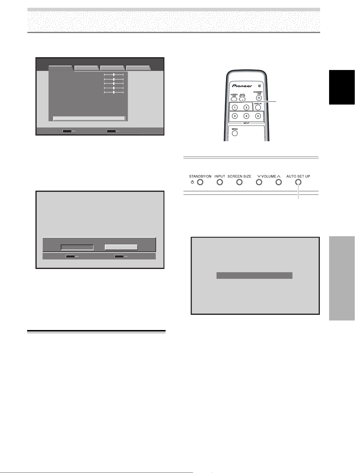
Réglage de l’image et de son affichage
3 Utilisez les touches 5/∞ pour sélectionner [RÉINIT.
IMAGE], puis appuyez sur la touche SET.
STANDARD ENTRÉE1
IMAGE ÉCRAN SETUP OPTION
CONTRASTE
LUMINOSITÉ
COULEUR
TEINTE
NETTETÉ
MPEG NR
DNR
CTI
TEMP. COULEUR:MOYEN
RÉINIT. IMAGE
SET
ENTRÉE
:
0
:
0
:
0
:
0
:
0
:
MARCHE
:
MOYEN
:
MARCHE
MENU
SORTIE
4 Utilisez les touches 2/3 pour sélectionner [OUI],
puis appuyez sur la touche SET.
Les valeurs des paramètres image correspondant à
l’ENTRÉE et au mode AV SELECTION sélectionnés,
sont à nouveau ce qu’elles étaient à la sortie d’usine,
puis la page affichée au cours de l’opération 3 est
rétablie.
Lorsque vous appuyez sur cette touche, les
réglages sont automatiquement adoptés en
fonction de l’image fournie par la source.
AUTO
SET UP
Boîtier de télécommande
AUTO SET UP
Panneau de commande de l’écran à plasma
Français
RÉINIT. IMAGE?
OUI NON
SET
VALIDER
MENU
SORTIE
5 Appuyez sur la touche MENU pour abandonner la
page de menu lorsque le paramétrage est terminé.
Remarque
Le paramètre [RÉINIT. IMAGE] ne concerne que l’ENTRÉE et le
mode AV SELECTION sélectionnés. Il ne peut pas concerner en
même temps plusieurs ENTRÉES et plusieurs valeurs de AV
SELECTION.
Réglage de POSITION, HORLOGE et
PHASE (Réglage automatique)
Tandis que le signal appliqué à l’entrée provient d’un
ordinateur personnel, vous pouvez, en appuyant sur la
touche AUTO SET UP du boîtier de télécommande ou du
panneau de commande de l’écran, obtenir le réglage
optimal de position de l’image et celui de l’horloge en
tenant compte du signal fournie par la source.
Appuyez sur la touche AUTO SET UP, sur l’écran ou
sur le boîtier de télécommande.
PARAMÉTRAGE AUTO.
Réglage de l’image et de son affichage
Remarques
¶ Ce réglage n’est possible que si le signal provenant de
l’ordinateur personnel est appliqué sur INPUT1.
¶ Effectuez ce réglage pour chaque type de signal.
¶ La détermination des valeurs optimales peut être impossible
dans le cas des signaux de faible luminance et de certains
autres signaux. Dans ce cas, procédez comme il est dit à la
section “Réglage de POSITION, HORLOGE, et PHASE
(Réglage manuel)” de cette même page.
¶ Lorsque vous effectuez le paramétrage automatique,
POSITION, HORLOGE et PHASE sont automatiquement réglés
même si vous réalisez un réglage manuel à la suite des
opérations décrites dans la section qui suit.
35
FR
Page 90

Réglage de l’image et de son affichage
Réglage de POSITION, HORLOGE et
PHASE (Réglage manuel)
Procédez comme il est dit ci-dessous pour sauvegarder
les valeurs pour chaque ENTRÉE.
Français
(Menu dans le cas d’un signal provenant d’un appareil
vidéo et appliqué via INPUT1 ou INPUT5.)
STANDARD ENTRÉE1
IMAGE ÉCRAN SETUP OPTION
POSITION
RÉINIT. ÉCRAN
:
0 0
MENU
2/3
SET
5/∞
Boîtier de télécommande
1 Appuyez sur la touche MENU pour afficher la page
de menu.
STANDARD ENTRÉE1
IMAGE ÉCRAN SETUP OPTION
CONTRASTE
LUMINOSITÉ
RÉINIT. IMAGE
SET
Réglage de l’image et de son affichage
ENTRÉE
:
0
:
0
MENU
SORTIE
2 Utilisez les touches 2/3 pour sélectionner
[ÉCRAN].
(Menu dans le cas d’un signal provenant de
l’ordinateur personnel et appliqué via INPUT1.)
STANDARD ENTRÉE1
IMAGE ÉCRAN SETUP OPTION
POSITION
HORLOGE
PHASE
RÉINIT.ÉCRAN
:
0 0
:
0
:
0
SET
ENTRÉE
MENU
SORTIE
3 Utilisez les touches 5/∞ pour sélectionner le
paramètre, puis appuyez sur la touche SET.
STANDARD ENTRÉE1
IMAGE ÉCRAN SETUP OPTION
POSITION
HORLOGE
PHASE
RÉINIT.ÉCRAN
SET
ENTRÉE
:
0 0
:
0
:
0
MENU
SORTIE
4 Utilisez les touches 2/3 et 5/∞ pour sélectionner
la valeur désirée.
¶ Pour [POSITION], les touches 2/3 commandent le
déplacement dans le sens horizontal (H), et les
touches 5/∞ dans le sens vertical (V).
POSITION
HV
00
SET
SET
SET
VALIDER
¶ Utilisez les touches 2/3 pour régler [HORLOGE] et
[PHASE].
MENU
EXIT
MENU
SORTIE
36
FR
SET
ENTRÉE
MENU
SORTIE
HORLOGE
:
SET
VALIDER
MENU
0
SORTIE
Page 91

Réglage de l’image et de son affichage
5 Appuyez sur la touche SET.
En appuyant sur la touche SET vous mettez en
mémoire les valeurs adoptées puis la page affichée au
cours de l’opération 3 est rétablie.
6 Lorsque le réglage est achevé, appuyez sur la
touche MENU pour rétablir la page standard.
Réglages des paramètres pour un signal d’ordinateur
personnel
POSITION
H ........................... Agit sur la position horizontale de
l’image.
V ............................ Agit sur la position verticale de
l’image.
HORLOGE............. Agit sur les caractères et le bruit
d’écran. Ce paramètre règle la
fréquence du signal d’horloge
interne de l’écran correspondant au
signal d’entrée vidéo.
PHASE .................. Ce paramètre permet de réduire le
scintillement des caractères et les
défauts d’alignement des couleurs. Il
agit sur la phase du signal d’horloge
qui a été réglé grâce au paramètre
[HORLOGE].
Pour rétablir la valeur par défaut de [ÉCRAN]
1 Utilisez les touches 5/∞ pour sélectionner [RÉINIT.
ÉCRAN] au cours de l’opération 3 précédente, puis
appuyez sur la touche SET.
RÉINIT. ÉCRAN?
OUI NON
SET
VALIDER
MENU
SORTIE
2 Utilisez les touches 2/3 pour sélectionner [OUI],
puis appuyez sur la touche SET.
Les valeurs du paramètre [ÉCRAN] correspondant à
l’entrée sélectionnée, sont à nouveau ce qu’elles
étaient à la sortie d’usine.
Français
Réglages des paramètres pour un signal d’entrée
vidéo
POSITION
H ........................... Agit sur la position horizontale de
l’image.
V ............................ Agit sur la position verticale de
l’image.
Remarques
¶ Le réglage de [HORLOGE] et de [PHASE] est possible dans le
cas d’un signal provenant d’un ordinateur personnel et
appliqué via INPUT1.
¶ Après une modification de la valeur de [HORLOGE], celle de
[POSITION] peut exiger un nouveau réglage dans le sens
horizontal [H].
¶ Si les valeurs retenues pour le paramètre [ÉCRAN] sont
excessives, il se peut que l’image ne s’affiche pas
convenablement.
¶ Les valeurs pour ENTRÉE1 est sauvegardée séparément selon
qu’il s’agisse d’un signal vidéo ou d’un signal d’ordinateur
personnel.
Réglage de l’image et de son affichage
37
FR
Page 92

Autres opérations
Sélection du mode PURECINEMA
Permet une lecture DVD de fidélité encore plus élevée
d’enregistrements de films et autres images.
Remarque
Effectuez les réglages séparément pour chaque entrée.
Français
3 Utilisez les touches 5/∞ pour sélectionner
[PURECINEMA], puis appuyez sur la touche SET.
STANDARD ENTRÉE1
IMAGE ÉCRAN SETUP OPTION
PURECINEMA
POSITION CLAMP
TYPE DE SIGNAL
DÉCODAGE COULEUR
ENTRÉE HDMI
:
ARRÊT
:
AUTO
:
480p
:
COMPOSANTE
MENU
2/3
SET
5/∞
Boîtier de télécommande
1 Appuyez sur la touche MENU pour afficher la page
de menu.
STANDARD ENTRÉE1
IMAGE ÉCRAN SETUP OPTION
:
0
:
0
:
0
:
0
:
0
:
MARCHE
:
MOYEN
:
MARCHE
:
MENU
SORTIE
Autres opérations
CONTRASTE
LUMINOSITÉ
COULEUR
TEINTE
NETTETÉ
MPEG NR
DNR
CTI
TEMP. COULEUR MOYEN
RÉINIT. IMAGE
SET
ENTRÉE
2 Utilisez les touches 2/3 pour sélectionner
[SETUP].
STANDARD ENTRÉE1
IMAGE ÉCRAN SETUP OPTION
PURECINEMA
POSITION CLAMP
TYPE DE SIGNAL
DÉCODAGE COULEUR
ENTRÉE HDMI
SET
ENTRÉE
:
ARRÊT
:
AUTO
:
480p
:
COMPOSANTE
MENU
SORTIE
38
FR
SET
ENTRÉE
MENU
SORTIE
4 Utilisez les touches 2/3 pour sélectionner le
mode [PURECINEMA] désiré.
ARRÊT
PURECINEMA
SET
VALIDER
Valeur de réglage par défaut à la fabrique
Lors de l’entrée d’un signal 480p ou 720p: ARRÊT
Lors de l’entrée d’un signal vidéo autre que ceux cidessus: STANDARD
Chaque pression sur cette touche provoque la
sélection d’un autre mode, comme suit:
[PDP-5004, PDP-4304]
3 ARRÊT 23 STANDARD 2
3 AVANCÉ 2
¶ ARRÊT............ La fonction [PURECINEMA] n’est
pas en service.
¶ STANDARD .... Lors de la lecture de DVD ou de
films Hi-Vision à 24 images/seconde,
les données enregistrées sont
automatiquement détectées et les
réglages réalisés pour bénéficier
d’une expérience optimale au niveau
de la beauté originelle de l’image du
film.
¶ AVANCÉ ......... Lors de la lecture de DVD ou de
films Hi-Vision à 24 images/seconde,
l’information vidéo enregistrée est
automatiquement détectée et les
signaux sont convertis à 72 Hz pour
la lecture, permettant ainsi une
recréation du mouvement fluide
d’un film projeté dans une salle de
cinéma, ainsi que le sentiment de
qualité visuelle véritable inhérente
au film.
Remarque
Vous ne pouvez pas sélectionner la valeur [STANDARD] si le
signal est à balayage progressif (entrée 480p ou 720p).
:
MENU
SORTIE
Page 93

Autres opérations
[PDP-5014, PDP-4314]
3 ARRÊT 2
3 STANDARD 2
¶ ARRÊT............ La fonction [PURECINEMA] n’est
pas en service.
¶ STANDARD .... Lors de la lecture de DVD ou de
films Hi-Vision à 24 images/seconde,
les données enregistrées sont
automatiquement détectées et les
réglages réalisés pour bénéficier
d’une expérience optimale au niveau
de la beauté originelle de l’image du
film.
Remarque
Vous ne pouvez pas sélectionner [PURECINEMA] lors de l’entrée
d’un signal à balayage progressif 480p ou 720p.
5 Appuyez sur la touche SET.
La fonction [PURECINEMA] est mise en service puis
la page affichée au cours de l’opération 3 est rétablie.
6 Lorsque le réglage est achevé, appuyez sur la
touche MENU pour rétablir la page standard.
1 Appuyez sur la touche MENU pour afficher la page
de menu.
STANDARD ENTRÉE1
IMAGE ÉCRAN SETUP OPTION
CONTRASTE
LUMINOSITÉ
COULEUR
TEINTE
NETTETÉ
MPEG NR
DNR
CTI
TEMP. COULEUR MOYEN
RÉINIT. IMAGE
SET
ENTRÉE
:
0
:
0
:
0
:
0
:
0
:
MARCHE
:
MOYEN
:
MARCHE
:
MENU
SORTIE
2 Utilisez les touches 2/3 pour sélectionner
[OPTION].
STANDARD ENTRÉE1
IMAGE ÉCRAN SETUP OPTION
LANGUAGE FRANÇAIS
ÉCONOM. D'ÉNERGIE
GESTION D'ALIM.
ARRÊT AUTOMATIQUE DÉSACTIVÉ
ORBITER ARRÊT
CONTRÔLE MASQUE MARCHE
:
:
STANDARD
:
ARRÊT
:
:
:
Français
Réglages d’économie d’énergie
(ÉCONOM. D’ÉNERGIE)
Cette fonction réduit la luminosité de l’écran pour
diminuer la consommation d’énergie et éviter la
dégradation de ce dernier.
MENU
2/3
SET
5/∞
3 Utilisez les touches 5/∞ pour sélectionner
[ÉCONOM. D’ÉNERGIE], puis appuyez sur la
touche SET.
STANDARD ENTRÉE1
IMAGE ÉCRAN SETUP OPTION
:
MENU
FRANÇAIS
:
STANDARD
:
ARRÊT
:
:
:
SORTIE
LANGUAGE
ÉCONOM. D'ÉNERGIE
GESTION D'ALIM.
ARRÊT AUTOMATIQUE DÉSACTIVÉ
ORBITER ARRÊT
CONTRÔLE MASQUE MARCHE
SET
ENTRÉE
4 Utilisez les touches 2/3 pour sélectionner le
paramètre [ÉCONOM. D’ÉNERGIE].
Autres opérations
Boîtier de télécommande
ÉCONOM. D'ÉNERGIE
SET
VALIDER
:
MENU
STANDARD
SORTIE
La valeur par défaut est [STANDARD].
Chaque pression sur les touches 2/3, modifie le
réglage, comme suit:
39
FR
Page 94

Autres opérations
3 STANDARD 2
3 MODE3 23 MODE2 23 MODE1 2
¶ STANDARD .... La luminosité est réglée en fonction
du signal d’entrée pour produire des
images lumineuses mais faciles à
regarder.
Français
¶ MODE1 .......... La luminosité est réglée en fonction
du signal d’entrée mais la
consommation d’énergie est
inférieure à celle du mode
[STANDARD].
¶ MODE2 .......... La luminosité est réglée en fonction
du signal d’entrée mais la
consommation d’énergie est
inférieure à celle du mode [MODE1].
¶ MODE3 .......... La luminosité est fixe et
indépendante du signal d’entrée.
Cette valeur réduit le vieillissement
de l’écran dû aux phénomènes de
brûlage, etc.
5 Appuyez sur la touche SET.
La fonction [ÉCONOM. D’ÉNERGIE] est mise en
service puis la page affichée au cours de l’opération 3
est rétablie.
6 Lorsque le réglage est achevé, appuyez sur la
touche MENU pour rétablir la page standard.
Remarque
La valeur adoptée pour [ÉCONOM. D’ÉNERGIE] a un effet sur
toutes le entrées.
Mise hors tension automatique
(GESTION D’ALIM.)
Autres opérations
Cet appareil possède deux fonctions, [GESTION D’ALIM.]
et [ARRÊT AUTOMATIQUE] de gestion de l’alimentation;
en l’absence de détection de signal de synchronisation,
l’appareil se met en veille ou hors service (un message
d’avertissement est affiché avant que ces fonctions
n’opèrent).
Remarques
¶ La fonction de gestion d’alimentation ne joue un rôle que si un
signal provenant de l’ordinateur personnel est appliqué à
l’entrée INPUT1.
¶ La fonction de mise hors service automatique ne joue un rôle
que dans les cas autres que celui mentionné ci-dessus.
¶ N’oubliez pas de couper l’alimentation de l’appareil au moyen
de l’interrupteur prévu à cet effet dès lors que vous envisagez
de ne pas l’utiliser pendant une longue période.
INPUT
MENU
2/3
SET
Boîtier de télécommande
1 Appuyez sur la touche MENU pour afficher la page
de menu.
STANDARD ENTRÉE1
IMAGE ÉCRAN SETUP OPTION
CONTRASTE
LUMINOSITÉ
COULEUR
TEINTE
NETTETÉ
MPEG NR
DNR
CTI
TEMP. COULEUR MOYEN
RÉINIT. IMAGE
SET
ENTRÉE
:
0
:
0
:
0
:
0
:
0
:
MARCHE
:
MOYEN
:
MARCHE
:
MENU
SORTIE
2 Utilisez les touches 2/3 pour sélectionner
[OPTION].
STANDARD ENTRÉE1
IMAGE ÉCRAN SETUP OPTION
LANGUAGE FRANÇAIS
ÉCONOM. D'ÉNERGIE
GESTION D'ALIM.
ARRÊT AUTOMATIQUE DÉSACTIVÉ
ORBITER ARRÊT
CONTRÔLE MASQUE MARCHE
:
:
STANDARD
:
ARRÊT
:
:
:
3 Appuyez sur les touches 5/∞ pour sélectionner
[GESTION D’ALIM.] ou [ARRÊT AUTOMATIQUE],
puis appuyez sur la touche SET.
STANDARD ENTRÉE1
IMAGE ÉCRAN SETUP OPTION
LANGUAGE
ÉCONOM. D'ÉNERGIE
GESTION D'ALIM.
ARRÊT AUTOMATIQUE DÉSACTIVÉ
ORBITER ARRÊT
CONTRÔLE MASQUE MARCHE
:
FRANÇAIS
:
STANDARD
:
ARRÊT
:
:
:
40
FR
SET
ENTRÉE
MENU
SORTIE
Page 95

Autres opérations
4 Appuyez sur les touches 2/3 pour valider la
sélection de [GESTION D’ALIM.] ou de [ARRÊT
AUTOMATIQUE].
5 Appuyez sur la touche SET.
La fonction [GESTION D’ALIM.], ou [ARRÊT
AUTOMATIQUE], est mise en service puis la page
affichée au cours de l’opération 3 est rétablie.
Selection de GESTION D’ALIM.
GESTION D'ALIM.
SET
VALIDER
Selection de ARRÊT AUTOMATIQUE
:
MENU
ARRÊT
SORTIE
6 Lorsque le réglage est achevé, appuyez sur la
touche MENU pour rétablir la page standard.
Pour rétablir le fonctionnement:
¶ Pour revenir au fonctionnement normal après la mise en
veille par la fonction [GESTION D’ALIM.], faites
fonctionner l’ordinateur, ou bien appuyez une fois sur la
touche STANDBY/ON de l’appareil ou du boîtier de
télécommande.
¶ Pour revenir au fonctionnement normal après la
coupure d’alimentation par la fonction [ARRÊT
AUTOMATIQUE], appuyez sur la touche STANDBY/ON
de l’appareil ou du boîtier de télécommande.
Réglage de l’orbiteur (ORBITER)
À intervalles réguliers et définis (environ toutes les 8
minutes), cette fonction modifie légèrement et au hasard
la position verticale ou horizontale de l’image.
Lors de l’affichage d’une image fixe, le réglage de
[ORBITER] sur [MARCHE] évite les brûlages d’écran et la
création d’une image rémanente.
¶ Cette fonction n’est pas disponible dans le cas de
l’affichage de plusieurs images ni de l’affichage d’un
menu.
Français
ARRÊT AUTOMATIQUE
SET
VALIDER
:
MENU
DÉSACTIVÉ
SORTIE
Au moment de quitter l’usine, le paramètre GESTION
D’ALIM. a pour valeur [ARRÊT], et le paramètre
ARRÊT AUTOMATIQUE a pour valeur [DÉSACTIVÉ].
Chaque pression sur les touches 2/3, modifie le
réglage, comme suit:
3 ARRÊT/DÉSACTIVÉ 2
3 MARCHE/ACTIVÉ 2
÷ ARRÊT/DÉSACTIVÉ....
L’appareil demeure en mode de fonctionnement
indépendamment de la présence, ou de l’absence,
d’un signal d’entrée de synchronisation.
¶ GESTION D’ALIM.:MARCHE....
Si le signal de synchronisation n’est pas détecté, un
message d’avertissement est affiché pendant 8
secondes, à la suite de quoi, l’appareil passe en
veille tandis que le témoin STANDBY s’éclaire
(couleur rouge). Quand un signal de synchronisation
(*1) est à nouveau appliqué à l’entrée, l’appareil
repasse en mode normal de fonctionnement.
*1 Sauf si le signal est de type G ON SYNC ou composite.
÷ ARRÊT AUTOMATIQUE: ACTIVÉ....
Si aucun signal de synchronisation n’est détecté
pendant au moins 8 minutes, un message
d’avertissement s’affiche durant 30 secondes puis
l’alimentation de l’appareil est coupée.
Autres opérations
MENU
2/3
SET
5/∞
Boîtier de télécommande
41
FR
Page 96

Autres opérations
1 Appuyez sur la touche MENU pour afficher la page
de menu.
STANDARD ENTRÉE1
IMAGE ÉCRAN SETUP OPTION
:
0
:
0
:
0
:
0
:
0
:
MARCHE
:
MOYEN
:
MARCHE
:
MENU
SORTIE
Français
CONTRASTE
LUMINOSITÉ
COULEUR
TEINTE
NETTETÉ
MPEG NR
DNR
CTI
TEMP. COULEUR MOYEN
RÉINIT. IMAGE
SET
ENTRÉE
2 Utilisez les touches 2/3 pour sélectionner
[OPTION].
STANDARD ENTRÉE1
IMAGE ÉCRAN SETUP OPTION
LANGUAGE FRANÇAIS
ÉCONOM. D'ÉNERGIE
GESTION D'ALIM.
ARRÊT AUTOMATIQUE DÉSACTIVÉ
ORBITER ARRÊT
CONTRÔLE MASQUE MARCHE
:
:
STANDARD
:
ARRÊT
:
:
:
3 Utilisez les touches 5/∞ pour sélectionner
[ORBITER], puis appuyez sur la touche SET.
STANDARD ENTRÉE1
IMAGE ÉCRAN SETUP OPTION
:
LANGUAGE
ÉCONOM. D'ÉNERGIE
GESTION D'ALIM.
ARRÊT AUTOMATIQUE DISABLE
ORBITER ARRÊT
CONTRÔLE MASQUE MARCHE
FRANÇAIS
:
STANDARD
:
ARRÊT
:
:
:
5 Appuyez sur la touche SET.
La fonction [ORBITER] est mise en service puis la
page affichée au cours de l’opération 3 est rétablie.
6 Lorsque le réglage est achevé, appuyez sur la
touche MENU pour rétablir la page standard.
Remarque
La valeur adoptée pour [ORBITER] a un effet sur toutes les
entrées.
Position du cache latéral
(CONTRÔLE MASQUE)
Lorsque le format d’image est [POINT PAR POINT] ou
[4:3], et également pendant l’affichage de plusieurs
image, la position de tous les éléments est légèrement
modifiée au moment de chaque mise en service de
manière à éviter les risques de brûlage et la formation
d’image rémanente.
MENU
2/3
4 Appuyez sur les touches 2/3 pour valider le
Autres opérations
réglage.
ORBITER
:
SET
VALIDER
La valeur par défaut est [ARRÊT].
Chaque pression sur les touches 2/3, modifie le
réglage, comme suit:
3 ARRÊT 2
3 MARCHE 2
MENU
ARRÊT
SORTIE
SET
5/∞
Boîtier de télécommande
1
Appuyez sur la touche MENU pour afficher la page
de menu.
STANDARD ENTRÉE1
IMAGE ÉCRAN SETUP OPTION
CONTRASTE
LUMINOSITÉ
COULEUR
TEINTE
NETTETÉ
MPEG NR
DNR
CTI
TEMP. COULEUR MOYEN
RÉINIT. IMAGE
SET
ENTRÉE
:
0
:
0
:
0
:
0
:
0
:
MARCHE
:
MOYEN
:
MARCHE
:
MENU
SORTIE
42
FR
Page 97

2 Utilisez les touches 2/3 pour sélectionner
[OPTION].
STANDARD ENTRÉE1
IMAGE ÉCRAN SETUP OPTION
LANGUAGE FRANÇAIS
ÉCONOM. D'ÉNERGIE
GESTION D'ALIM.
ARRÊT AUTOMATIQUE DÉSACTIVÉ
ORBITER ARRÊT
CONTRÔLE MASQUE MARCHE
:
:
STANDARD
:
ARRÊT
:
:
:
3 Utilisez les touches 5/∞ pour sélectionner
[CONTRÔLE MASQUE], puis appuyez sur la touche
SET.
STANDARD ENTRÉE1
IMAGE ÉCRAN SETUP OPTION
:
LANGUAGE
ÉCONOM. D'ÉNERGIE
GESTION D'ALIM.
ARRÊT AUTOMATIQUE DÉSACTIVÉ
ORBITER ARRÊT
CONTRÔLE MASQUE MARCHE
FRANÇAIS
:
STANDARD
:
ARRÊT
:
:
:
Autres opérations
Français
4 Appuyez sur les touches 2/3 pour valider le
réglage.
CONTRÔLE MASQUE
SET
VALIDER
:
MENU
MARCHE
SORTIE
La valeur par défaut est [MARCHE].
Chaque pression sur les touches 2/3, modifie le
réglage, comme suit:
3 MARCHE 2
3 ARRÊT 2
5 Appuyez sur la touche SET.
La fonction [CONTRÔLE MASQUE] est mise en
service puis la page affichée au cours de l’opération 3
est rétablie.
6 Lorsque le réglage est achevé, appuyez sur la
touche MENU pour rétablir la page standard.
Autres opérations
Remarque
La valeur adoptée pour [CONTRÔLE MASQUE] a un effet sur
toutes les entrées.
43
FR
Page 98

Informations complémentaires
Nettoyage
Le nettoyage régulier de l’écran à plasma prolonge sa
durée de vie et permet de maintenir ses performances.
La manière de nettoyer l’écran est indiquée ci-après.
Français
Avant tout nettoyage, débranchez la fiche du cordon
d’alimentation.
Nettoyage du panneau de l’écran et du boîtier de
télécommande
N’utilisez aucun produit volatil tel que les essences ou les
diluants pour peinture, qui peuvent endommager la
finition de l’écran ou du boîtier de télécommande.
Nettoyez l’écran à plasma au moyen d’un chiffon sec et
doux. Dans le cas des taches tenaces, vous pouvez
utilisez un chiffon humecté d’une solution étendue de
détergent. Essorez soigneusement le chiffon avant de
frotter les taches. Essuyez ensuite la surface avec un
chiffon sec.
Nettoyage de la surface de l’écran
Après avoir épousseté l’écran, essuyez-le avec le chiffon
fourni, ou un chiffon sec et doux. N’utilisez pas de
mouchoir en papier ni de chiffon rugueux. La surface de
l’écran peut facilement être rayée; ne frottez aucun objet
dur sur cette surface.
Nettoyage des ouïes d’aération
En règle générale, utilisez un aspirateur une fois par mois
pour nettoyer les ouïes, à l’arrière de l’écran à plasma (si
cela est possible, réglez au minimum la puissance de
l’aspirateur).
Pour éviter toute anomalie de fonctionnement, une
surchauffe de l’écran à plasma et un incendie, veillez à ce
que les ouïes d’aération ne soient pas obstruées.
Informations complémentaires
Ouïes
L’illustration représente le modèle PDP-5004.
44
FR
Ouïes
Ouïes
Guide de dépannage
Une erreur de commande peut parfois être interprétée
comme une anomalie de fonctionnement. Si une
indication est affichée sur l’écran, consultez le tableau cidessous. Dans le cas contraire, et si vous pensez que cet
appareil est défectueux, procédez aux vérifications de la
page 45. Il peut arriver aussi que le défaut provienne d’un
autre élément de l’installation; assurez-vous que ce n’est
pas le cas. Si, en dépit de ces contrôles, vous n’êtes pas
en mesure d’obtenir un fonctionnement satisfaisant,
consultez le revendeur.
Quelques mots sur l’autodiagnostic
Des messages peuvent apparaître au centre de l’écran,
qui indiquent une anomalie de fonctionnement ou de
raccordement. Après avoir pris connaissance du message,
vérifiez l’état de l’appareil et des liaisons.
Messages d’erreur
ATTENTION
FREQ. HORS STANDARD
ou
ATTENTION
SIGNAL NON RECONNU
ou
SIGNAL INCORRECT
DANGER
ALERTE TEMPÉRATURE
COUPURE ALIM.(**)
DANGER
DÉFAUT VENTILATION
COUPURE ALIM.(**)
ERREUR
OuïesOuïes
OPÉRATION INVALIDE
COUPURE ALIM.(**)
Dans les messages ci-dessus, (**) remplace les nombres
qui figurent dans les messages.
Actions correctives
¶
Le signal appliqué à l’entrée
n’est pas compatible avec
l’appareil. Reportez-vous aux
tableaux des pages 49 et 50
qui fournissent la liste des
signaux d’ordinateur acceptés,
puis modifiez la sortie de
l’ordinateur en conséquence.
¶
Coupez l’alimentation de
l’appareil (page 10).
¶
La température ambiante estelle trop élevée?
¶
Retirez les objets qui
obstruent les ouïes d’aération
de l’écran à plasma.
¶
Le ventilateur de
refroidissement ne fonctionne
pas normalement. Coupez
immédiatement l’alimentation,
retirez la fiche du cordon
d’alimentation au niveau de la
prise secteur et consultez le
revendeur ou un service aprèsvente Pioneer.
¶
Vous avez tenté d’exécuter une
opération non prévue. Vérifiez
les signaux d’entrée, les
raccordements et les autres
réglages (par exemple:
affichage de plusieurs images).
¶
Coupez l’alimentation,
attendez une ou deux minutes
puis remettre l’appareil sous
tension. Si l’anomalie persiste,
débranchez la fiche du cordon
d’alimentation au niveau de la
prise secteur et consultez le
revendeur ou un service aprèsvente Pioneer.
Page 99

Généralités
Incidents Actions correctives possibles
• Absence d’alimentation.
•L’appareil refuse de fonctionner.
•Le boîtier de télécommande ne
fonctionne pas.
•L’image est tronquée.
• Couleurs surprenantes, couleurs
délavées, couleurs sombres ou
mal alignées.
•L’alimentation se coupe
brusquement.
• Absence d’image.
Informations complémentaires
• ILa fiche du cordon d’alimentation est-elle débranchée? (page 19)
•L’interrupteur MAIN POWER est-il sur la position de marche? (page 10)
• Des phénomènes extérieurs tels qu’orage, charge d’électricité statique, etc. peuvent provoquer une anomalie
de fonctionnement. En ce cas, mettez l’écran à plasma hors tension puis sous tension, directement au moyen
de l’interrupteur MAIN POWER ou bien en débranchant la fiche du cordon d’alimentation puis en la rebranchant
1 ou 2 minutes plus tard.
•Les polarités (+, –) des piles sont-elles inversées? (page 8)
• Les piles sont-elles épuisées? (Remplacez-les par des piles neuves.)
• Un objet occulte-t-il le capteur de télécommande? (page 8)
• Dirigez le boîtier de télécommande vers le capteur de télécommande (page 8).
•Le format d’image choisi convient-il?
Sélectionnez un autre format de l’image (page 29).
•Le paramétrage de [ÉCRAN], et en particulier le choix du format, est-il correct? (pages 29 à 30 et 35 à 37)
• Réglez la tonalité de l’image (page 33).
• La pièce est-elle trop éclairée?
L’image peut paraître sombre dans une pièce trop éclairée.
•Le paramétrage de [POSITION CLAMP] est-il correct? (page 24)
• Le paramétrage de [ENTRÉE HDMI] est-il correct? (uniquement avec l’entrée HDMI) (pages 25 à 26)
• La température interne de l’appareil a augmenté (Ouïes obstruées).
Retirez les objets qui obstruent les ouïes, ou nettoyez celles-ci (page 44).
• La fonction [GESTION D’ALIM.] est-elle en service? (page 40)
• Les raccordements aux autres appareils sont-ils corrects? (pages 13 à 15)
• Après raccordements, le paramétrage a-t-il été réalisé convenablement? (pages 22 à 26)
•L’entrée désirée est-elle sélectionnée? (page 27)
• Le signal d’entrée est-il incompatible? (pages 48 à 50)
• La valeur de [IMAGE] est-elle correcte? (page 33)
Français
Incidents fréquemment confondus avec une anomalie
Incidents Actions correctives possibles
•L’image affichée est de petite
taille.
• Coupure de caractère affiché.
• Un son net est parfois émis par la
carrosserie de l’appareil.
•Les portions lumineuses
semblent être moins intenses.
• Du bruit parasite apparaît sur
l’écran.
• Des bandes de bruit apparaissent
sur l’écran.
•L’intérieur de l’appareil émet des
bruits.
•Le ventilateur ne tourne pas.
• La vitesse du ventilateur varie.
• Le format d’image choisi convient-il? (pages 29 à 30 et 35)
• Effectuez un réglage de [ÉCRAN] sur le menu image (page 36).
Si cela n’améliore rien, l’appareil peut volontairement limiter la taille de l’image. Reportez-vous aux tableaux de
compatibilité des signaux d’ordinateur personnel (pages 49 à 50).
• La dilatation et la contraction dues aux changements de température ambiante peuvent s’accompagner de
l’émission de bruit. Cela ne traduit pas une anomalie de fonctionnement.
•Lorsque le niveau d’entrée du signal vidéo est trop élevé, les portions lumineuses semblent être moins
intenses.
Augmentez le réglage de niveau et vérifiez les réglages image (page 33).
• Cela peut provenir d’un brouillage radioélectrique provoqué par des moteurs de sèche-cheveux, aspirateurs,
perceuses, démarreurs, motocyclettes, etc., des commutateurs tels que les thermostats, etc., des enseignes
au néon, des décharges électriques provenant des lignes de distribution, etc.
• Cela peut être dû au brouillage d’une station de télévision, d’une station de radio FM, d’un émetteur de radioamateur, d’une radio publique (radio simple), etc., ou encore à la présence, à proximité, d’un ordinateur
personnel, d’un téléviseur ou d’un appareil audiovisuel.
• Un champ électromagnétique puissant peut provoquer une déformation de l’image, ou une anomalie similaire.
• Ils proviennent probablement du ventilateur ou des organes intérieurs mobiles de l’écran à plasma. Cela ne
traduit pas une anomalie de fonctionnement.
•Le ventilateur ne se met en marche que lorsque la température intérieure atteint 35°C (95°F) (valeur qui dépend
de l’installation). Cela ne traduit pas une anomalie de fonctionnement.
• La vitesse du ventilateur varie avec les conditions ambiantes. Cela ne traduit pas une anomalie de
fonctionnement.
Informations complémentaires
45
FR
Page 100

Informations complémentaires
Précautions d’utilisation
Rémanence d’image sur le panneau
•L’affichage de la même image pendant une longue
période peut provoquer une rémanence de cette image.
Cela peut spécialement se produire dans les deux cas
Français
Informations complémentaires
circonstances suivants.
1. Persistance d’image due à une charge électrique
Si une image fixe très lumineuse est affichée pendant
plus d’une minute, une persistance de cette image peut
apparaître en raison d’une charge électrique résiduelle.
Ce phénomène s’atténue dès que des images animées
sont affichées. La durée du phénomène dépend de la
luminosité et de la durée de l’image initiale.
2. Image rémanente due au brûlage
Évitez d’afficher sur l’écran plasma la même image
pendant longtemps. Si la même image demeure sur
l’écran pendant plusieurs heures, ou encore apparaît
tous les jours au cours d’une période plus courte mais
répétée, une image rémanente peut être produite par
brûlage de la couche fluorescente de l’écran. Cette
image rémanente devient moins visible après
l’affichage d’images animées mais elle ne disparaît
jamais complètement.
Le même phénomène de brûlage peut se produire
après une utilisation brève mais quotidienne et
répétée impliquant une image au format 4/3 ou une
image [POINT PAR POINT], à l’exclusion de toute
autre. À moins que des considérations de droits
d’auteur ne vous l’interdisent (pages 29 à 30), nous
vous conseillons de choisir un format couvrant toute la
surface de l’écran de manière à réduire les chances de
brûlage (pages 29 à 30).
• Par ailleurs, les fonctions [ÉCONOM. D’ÉNERGIE]
(page 39), [ORBITER] (page 41) et [CONTRÔLE
MASQUE] (page 42), peuvent être utilisées avec profit
pour réduire les chances de brûlage.
Quelques mots sur la protection du panneau à
plasma
La luminosité de ce panneau diminue légèrement si une
image fixe ou peu animée (photo ou image ordinateur) est
affichée pendant longtemps. Cela est provoqué
volontairement par les circuits de protection qui détecte la
présence d’une telle image et réduisent
automatiquement la luminosité; il ne s’agit pas d’une
anomalie.
Ces circuits agissent lorsqu’une image fixe ou peu
animée est présente depuis plus de 3 minutes environ;
leur mise en service est automatique et ne peut pas être
arrêtée.
Pixel défectueux
Cet écran comprend un grand nombre d’éléments
d’image (pixels) formant un réseau de grande précision; il
peut arriver qu’un ou plusieurs éléments ne s’éclairent
pas, ou s’éclairent de manière inopinée. Cela tient à la
technique de fabrication et ne traduit pas une anomalie.
Au sujet du rayonnement infrarouge
Par principe, l’écran à plasma émet un rayonnement
infrarouge. En fonction de son environnement et de son
utilisation, l’écran peut perturber le fonctionnement des
appareils voisins qui réagissent à ce rayonnement, et
même se traduire par un brouillage des téléphones sans
fil. Dans une telle situation, éloignez de l’écran l’appareil
concerné.
Brouillage électromagnétique
Cet appareil est fabriqué conformément aux normes visant
à limiter les brouillages électromagnétique, ce qui
n’empêche pas qu’il émette un faible bruit radioélectrique.
Ce bruit peut perturber un poste de radio AM, un ordinateur
ou un appareil vidéo qui seraient installés à proximité. Dans
une telle situation, éloignez de l’écran l’appareil concerné.
Précautions complémentaires
• Si l’alimentation de l’écran à plasma est
automatiquement coupée, les causes possibles sont
les suivantes.
1 La fonction [GESTION D’ALIM.] ou la fonction
[ARRÊT AUTOMATIQUE] n’est-elle pas réglée sur
[MARCHE/ACTIVÉ] ? (page 40)
2 La température ambiante est supérieure à 40°C
(104°F). Faites fonctionner l’écran à plasma à une
température ambiante inférieure à 40°C (104°F).
3 Les ouïes d’aération sont obstruées, ou bien la
température intérieure a subitement augmenté pour
une raison inconnue, etc.
Si l’alimentation est automatiquement coupée pour une
raison autre que celles-ci, il peut s’agir d’une anomalie de
fonctionnement. En ce cas, débranchez la fiche du cordon
d’alimentation et consultez le revendeur.
• La luminosité de l’écran à plasma est très élevée; être
trop près peut provoquer une fatigue visuelle. Nous vous
suggérons de vous placer à environ 3 à 6 m de l’écran.
• De manière à protéger les circuits et les organes
intérieurs de cet écran à plasma, la vitesse du ventilateur
intérieur augmente dès que la température extérieure
atteinte. (A ce moment-là, le bruit du ventilateur devient
plus puissant.) Faites fonctionner l’écran à plasma à une
température ambiante inférieure à 40°C (104°F).
Témoins STANDBY et ON
Quand le témoin ON clignote en vert, un message d’erreur est
affiché. Consultez les messages d’erreur (page 44) et vérifiez
les conditions ambiantes (température, etc.) puis procédez
comme il convient (page 45).
Dans tous les autres cas, si l’écran refuse de se mettre en
service, si son alimentation se coupe d’elle-même, si le
témoin STANDBY clignote (couleur rouge), une anomalie
s’est produite. Débranchez immédiatement la fiche du
cordon d’alimentation au niveau de la prise secteur et
consultez le revendeur ou un service après-vente.
46
FR
 Loading...