

Page 1

Table top stand
Pied de table
PDK-1015
Operating instructions
Mode d’emploi
Page 2
Thank you for buying Pioneer’s product.
Please read through the Operating Instructions to learn
how to operate your model safely and properly.
Please be advised to keep the Operating Instructions in
your place for future reference.
Installation
¶ Consult your dealer if you encounter any difficulties
with this installation.
¶ Pioneer is not liable for any damage resulting from
improper installation, improper use, modification, or
natural disasters.
Cautions
This product is a table top stand exclusively designed for
Plasma Display (PRO-1540HD / PDP-607XD) from Pioneer.
Use with other model is capable of resulting in instability
causing possible injury. For further information, please
contact the store where you purchased your display.
Do not install or modify the product other than specified.
Do not use this stand for a Plasma Display other than those
designated and do not modify it or use it for other
purposes.
IMPORTANT NOTICE
Record the model number and serial number of this
equipment below.
Model No. PDK-1015 Serial No.
Keep these numbers for future use.
Contents
Cautions ................................................................... 2
Checking the Standard Accessories ...................... 3
Assembling the Stand ............................................ 3
Attaching the Plasma Display ................................ 4
Installing the Product on a TV table etc. .............. 5
Preventing Equipment from Falling Over ............. 6
Preparing the cables ............................................... 7
Detaching the Plasma Display from the Stand .... 7
Specifications .......................................................... 8
Dimensions Diagram .............................................. 8
CAUTION
This symbol refers to a hazard or unsafe practice which
can result in personal injury or property damage.
Improper installation is extremely dangerous because it
may result in it falling over or other accident.
Installation Location
• Select a location that is strong enough to support the
weight of the stand and the displays.
• Make sure to place it in a level and stable location.
• Do not install it outdoors, at a hot spring, or near a beach.
• Do not install the stand where it may be subjected to
vibration or shock.
Assembling and Installation
• Assemble the stand in accordance with the assembly
instructions and securely attach all screws at the
designated locations.
There have been cases where unforeseen accidents
such as the equipment breaking or falling over
occurred after the installation of the display because
the stand was not installed as instructed.
• The display must always be installed by two or more
people to assure it is installed safely.
• Before installation, turn off the power for the display
and peripheral devices then remove the power cord
plug from the power outlet.
Prevent accidents caused by the product falling over by
taking reliable measures to prevent it from falling over (see
Page 6).
En
2
Page 3
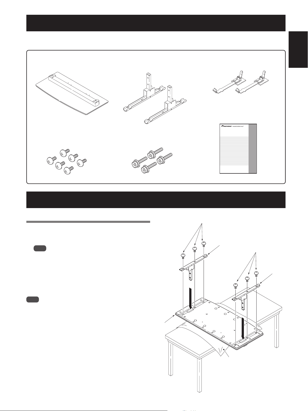
Checking the Standard Accessories
Check to make sure that you have all the standard accessories before assembly and installation.
• Note that a Phillips screwdriver (not included) is required for assembly.
Base cover x 1
Stand pipes
(left and right, interchangeable) x 2
Screws
(M5 x 10 mm: silver) x 6
Assembling the Stand
Installation bolts
(M6 x 20 mm: black) x 4
Cable clamps x 2
Operating instructions
(this document) x 1
Table top stand
Pied de table
PDK-1015
Operating instructions
Mode d’emploi
English
Assembly Procedure
1 Turn the base cover over so the underside
is facing up.
Note
When the base cover is turned over, be very careful not
to scratch or damage the front surface of the base cover.
2 Insert the stand pipes into the base cover.
3 Tighten the screws to stabilize the stand
pipes.
Note
Assemble the stand with a soft sheet placed under the
base cover.
If a sheet is not laid before assembly, the front surface of
the base cover may be scratched.
Due to the manufacturing process of the base cover, there
may be a “weld line” exposed in the plastic. Note that this
will not cause any damage to the product, and does not
reflect any flaws in the product design.
Base cover
Screws
(M5 x 10 mm: silver)
Stand pipe
Sheet
Screws
(M5 x 10 mm: silver)
Stand pipe
3
En
Page 4
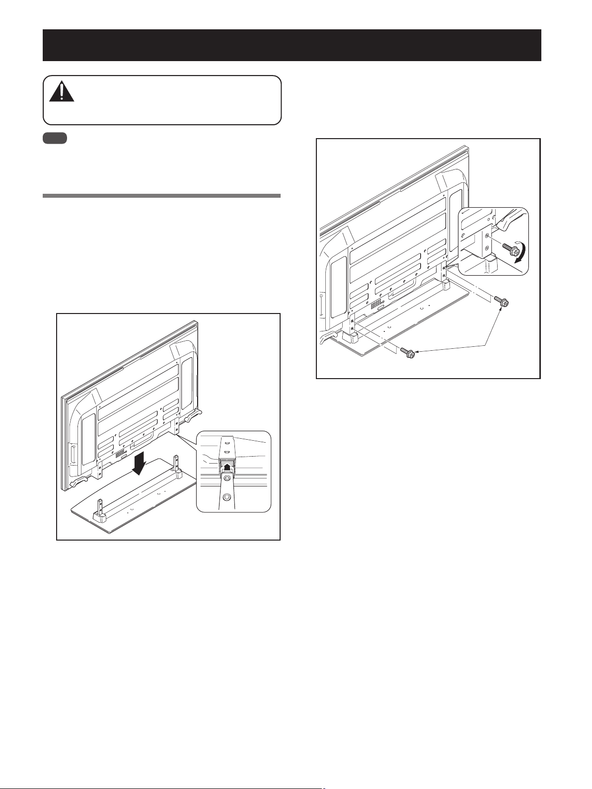
Attaching the Plasma Display
The weight of a Plasma Display is about 50 kg
(110 lbs), they have no depth, and are unstable.
Caution
Note
Be sure to install it on a flat stable location.
Insert the screws in the holes vertically and tighten them
firmly.
Therefore, at least two people must assemble and
install them.
Attachment Method
1 Attaching the Plasma Display to the stand.
Fit the stand’s support columns to the bottom of the
Plasma Display as indicated by the arrows, then slowly
insert them vertically. Be extremely careful not to insert the
support columns of the stand into any part of the Plasma
Display other than the stand insertion slots. Note that doing
so might damage the Plasma Display panel or its ports or
result in the warping of the stand.
2 Securing the Plasma Display with
Installation bolts.
Attach the Plasma Display at the points indicated below
using the phillips screwdriver.
Installation bolts
(M6 x 20 mm: black)
Line up the column
supports with the
bottom of the Plasma
Display as indicated
in the accompanying
diagram.
En
4
Page 5
Installing the Product on a TV table etc.
Be sure to observe the following precautions when moving
or installing this product with a Plasma Display into a TV
table or other enclosure.
When installing on a TV table, etc., please be sure
Caution
that the Plasma Display is held by two people.
Precautions when moving
When moving the product more than a few
meters, first remove the speaker, then remove
Caution
the Plasma Display from the stand and move the
speaker, Plasma Display, and stand separately.
When detaching the Plasma Display from the
stand, be sure to follow the procedure described
in “Detaching the Plasma Display from the
Stand” on page 7.
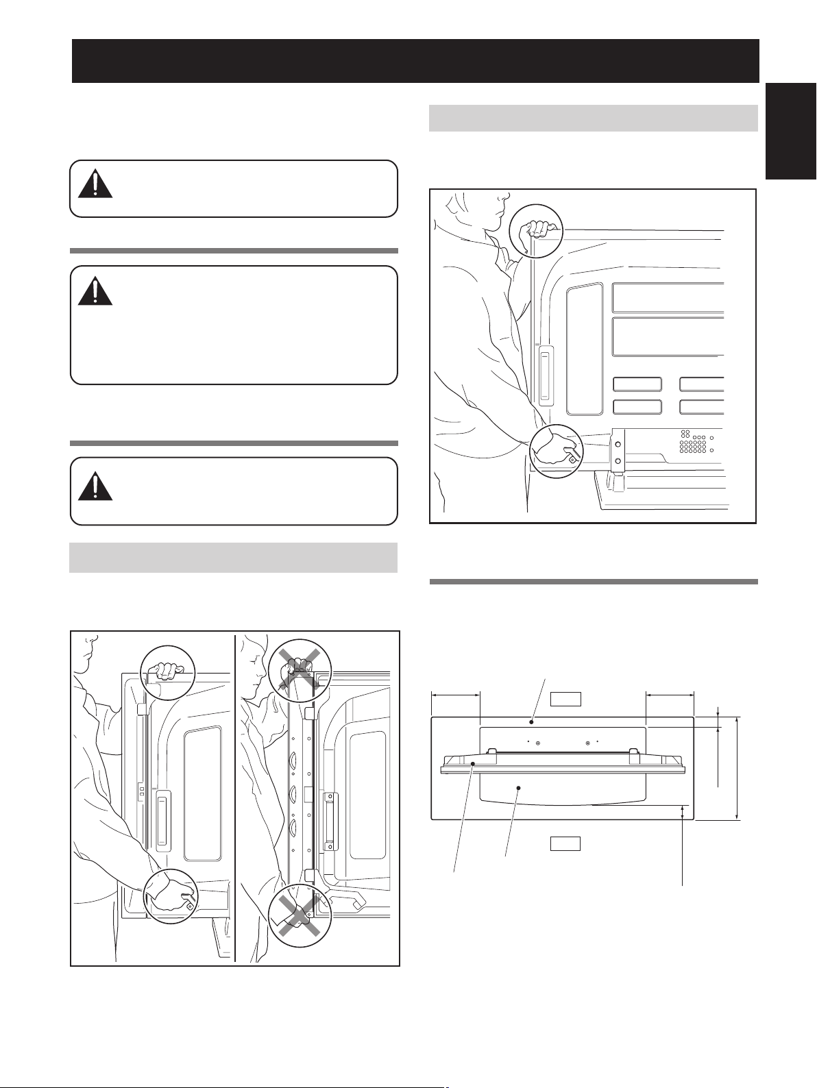
Precautions when installing in a TV
table or other enclosure
When installing in a TV table or other enclosure, hold
the Plasma Display by the handle at the bottom, with
Caution
your other hand hold the top. If you hold the speakers,
they may be damaged or twisted.
Except side speaker model
Hold the Plasma Display by the handle at the bottom, with
your other hand hold the top.
English
Do not hold the speaker
Hold the Plasma Display by the handle at the bottom, with
your other hand hold the top.
Installation precautions
Make sure that you always secure a space at least as large
as that shown in the following diagram in front of and
behind the table top stand.
Min. 30 mm
(1-3/16 inch)
Table top stand
Plasma Display
TV table
Back
Front
Min. 30 mm
(1-3/16 inch)
Min. 30 mm
Min. 10 mm
(13/32 inch)
Depth of the TV table
(1-3/16 inch)
500 mm (16-9/16 inch)
or more recommended
5
En
Page 6

Preventing Equipment from Falling Over
After installing the stand, be sure to take special care to ensure that the equipment will not fall over.
Because of the Plasma Display’s weight, if it could fall down, this can result in injury.
For safety, be sure to take special care to ensure that the Plasma Display will not fall over.
Stabilizing on TV table or other location
Stabilize the equipment as shown in the diagram using
screws that are available on the market.
Note
A TV table with adequate strength, width and depth
should always be used to support the Plasma Display.
Failure to do so could result in falling over.
To stabilize the Plasma Display on a TV table, use screws
that have a nominal diameter of 6 mm (1/4 inch).
Select the appropriate screws after consulting a professional installer if necessary.
6 mm
Min. 20 mm
(3/8 to 5/8 inch)
9 mm to 15 mm
(13/16 inch)
Using a wall for stabilization
1 Attaching falling prevention bolts (hooks)
to the Plasma Display.
2 Using strong cords to stabilize it
appropriately and firmly to a wall, pillar, or
other sturdy element.
Perform this work in the same way on the left and right
sides.
Note
Use hooks, cords, and fittings that are
available on the market.
Recommended hook:
(1/4 inch)
Nominal diameter M8
Length 12 mm to 15 mm (1/2 inch to
5/8 inch)
1 Hook
2 Cord
Fitting
12 mm to 15 mm
(1/2 inch to 5/8 inch)
M8
Position of table screws
When stabilizing the stand to a TV table, use nominal
diameter 6 mm (1/4 inch) with a length above
20 mm (13/16 inch).
Unit: mm (inch)
300
(11-13/16)
Side View
(23-1/32)
6
En
585
4.2 (5/32)
95 (3-3/4)
375 (14-3/4)
Caution
• A table or an area of the floor with adequate strength
should always be used to support the Plasma Display.
Failure to do so could result in personal injury and
physical damage.
• When installing the Plasma Display, please take the
necessary safety measures to prevent it from falling or
overturning in case of emergencies, such as
earthquakes, or of accidents.
• If you do not take these precautions, the Plasma
Display could fall down and cause injury.
• The screws, hooks, chains and other fittings that you
use to secure the Plasma Display to prevent it from
overturning will vary according to the composition and
thickness of the surface to which it will be attached.
• Select the appropriate screws, hooks, chains and other
fittings after first inspecting the surface carefully to
determine its thickness and composition and after
consulting a professional installer if necessary.
Page 7

Preparing the cables
Use the enclosed cable clamps to bind the cables.
Note
Be very careful not to apply force to the bases of the cables.
1 Insert the cable clamps into the cable
clamp mounting holes.
Cable clamps
Cable clamp
mounting holes
2 Bundle the cables and place them on each
cable clamp.
3 Close each cable clamp, and then pull its
extremity to make the cables immobile.
English
Loosening a cable clamp
If a cable clamp is closed
too tight, press the
button shown on the left
and push the extremity
of the cable clamp to
loosen it.
Button
Opening a cable clamp
Detaching the Plasma Display from the Stand
To remove the Plasma Display from the stand, be sure
to always follow the procedure described below to
Caution
prevent accidents.
1 First clear a space on a flat floor etc. where
you can lay the Plasma Display flat, then
lay a sheet to protect it from scratches or
other damage.
2 Remove the speakers.
3 Referring to step 2 in “Attaching the
Plasma Display” (Page 4.), remove the
installation bolts (4 screws).
4 Holding the Plasma Display by its handles
at the bottom, with your other hand hold
the top, lift the display vertically.
5 Place the Plasma Display slowly onto the
sheet laid out in step 1 with its screen
facing downwards.
Unlock here
with a finger.
7
En
Page 8

Specifications
External dimensions 1000 mm (W) x 222.5 mm (H) x 470 mm (D) (39-3/8 in. (W) x 8-3/4 in. (H) x 18-1/2 (D) in.)
Weight 10.0 kg (22.0 lbs)
• The above specifications and exterior may be modified without prior notice to improve the product.
Dimensions Diagram
Unit: mm (inch)
Side speaker model
118
1652 (65-1/16)
1470 (57-7/8)
SPEAKERSPEAKER
(4-21/32)
41 (1-5/8)
880 (34-5/8)
Except side speaker model
880 (34-5/8)
1000 (39-3/8)
1470 (57-7/8)
60
(2-1/3)
124.5
(4-7/8)
956 (37-5/8)
956 (37-5/8)
118
(4-21/32)
470 (18-1/2)
41 (1-5/8)
192.5
(7-19/32)
76 (3)
24 (31/32)
En
60
(2-1/3)
124.5
(4-7/8)
1000 (39-3/8)
470 (18-1/2)
Published by Pioneer Corporation.
8
Copyright © 2006 Pioneer Corporation.
All rights reserved.
192.5
(7-19/32)
76 (3)
24 (31/32)
Page 9

Nous vous remercions d’avoir choisi un produit Pioneer.
Veuillez lire attentivement ce mode d’emploi pour savoir
comment utiliser votre support correctement et en toute
sécurité. Nous vous conseillons de conserver
soigneusement ce mode d’emploi à portée de main et
dans un endroit sûr afin de pouvoir vous y référer le cas
échéant.
Installation
En cas de difficultés, veuillez consulter votre revendeur.
Pioneer ne saurait être tenu responsable d’aucun dommage
résultant d’une installation ou d’une utilisation incorrecte de
ce produit, de sa modification ou encore de catastrophes
naturelles.
AVIS IMPORTANT
Veuillez prendre note du numéro du modèle et du numéro de
série de cet équipement ci-dessous.
N° du modèle. PDK-1015 N° de série.
Conservez ces numéros pour pouvoir les utiliser
ultérieurement.
Table des matières
Attention .................................................................. 9
Vérification des pièces fournies........................... 10
Assemblage du support ....................................... 10
Attention
Ce produit est un pied de table conçu exclusivement pour
les écrans à plasma (PRO-1540HD / PDP-607XD) de
marque Pioneer.
L’utilisation de ce produit avec un autre modèle peut être à
l’origine d’un manque de stabilité pouvant provoquer une
blessure. Pour de plus amples informations, veuillez
contacter le magasin où vous avez acheté votre écran.
Ne procédez en aucun cas à installer ou à modifier le
produit autrement qu’en suivant les indications fournies. En
outre, n’utilisez pas ce support pour un écran à plasma
autre que celui pour lequel il a été conçu et ne le modifiez
pas ou ne l’utilisez pas à des fins autres que celles pour
lesquelles il a été conçu.
Une installation incorrecte est extrêmement dangereuse
car elle peut provoquer la chute du support ou tout autre
accident.
Lieu d’installation
• Sélectionnez un emplacement assez solide pour supporter le poids du support et de l’écran.
• Assurez-vous de placer le produit à un emplacement
stable et plat.
• N’installez pas le support à l’extérieur, à proximité d’une
source thermale ou sur une plage.
• N’installez pas le support à un endroit où il pourrait être
soumis à des chocs ou à des vibrations.
Français
Installation et fixation de l’écran à plasma......... 11
Installation du produit sur un meuble de
télévision, etc. ....................................................... 12
Prévenir toute chute de l’équipement ................ 13
Préparation des câbles ......................................... 14
Démontage de l’écran à plasma du support ...... 14
Caractéristiques techniques................................. 15
Schéma de dimensions ........................................ 15
ATTENTION
Ce symbole indique un danger ou une pratique dangereuse
susceptible de provoquer des dommages corporels ou
matériels.
Montage et installation
• Montez le support en suivant les instructions et
vissez solidement toutes les vis aux endroits prévus à
cet effet. Des accidents ont été constatés (casse,
chute du matériel, etc.) suite à l’installation de l’écran
parce que le support n’avait pas été installé
conformément aux instructions.
• Pour une bonne installation, l’écran doit toujours être
installé par au moins deux personnes.
• Avant de procéder à l’installation, mettez l’écran ainsi
que les équipements périphériques hors tension en
coupant l’alimentation, puis retirez la prise du câble
d’alimentation de la prise murale.
Prévenez les accidents causés par la chute du produit
en prenant des mesures fiables visant à éviter toute chute
(voir Page 13).
9
Fr
Page 10

Vérification des pièces fournies
Veuillez vous assurer que vous possédez bien toutes les pièces nécessaires avant de procéder au montage et à l’installation
du support.
• Veuillez prendre note qu’un tournevis de type Phillips (non inclus avec les pièces) pour vis à empreinte cruciforme est
nécessaire pour assembler le support de base.
Couverture de table x 1 unité
Vis (M5 x 10 mm : argentée) x 6 unités
Colonnes de support
(gauche et droite, interchangeables) x 2 unités
Vis d’installation
(M6 x 20 mm : noir) x 4 unités
Assemblage du support
Colliers de câble x 2 unités
Mode d’emploi
(ce document) x 1 exemplaire
Table top stand
Pied de table
PDK-1015
Operating instructions
Mode d’emploi
Procédure de montage
1 Tournez le pied de table de façon à ce
que le dessous regarde vers le haut.
Remarque
Veillez à ne pas endommager ni érafler le devant de la
couverture de table lorsqu’elle est sur l’envers.
2 Insérez les colonnes de support dans le
pied de table.
3 Serrez les vis afin de stabiliser les
colonnes de support.
Remarque
Avant de monter le support, glissez un drap doux sous la
couverture de table. Sans ce drap, vous risqueriez
d’érafler la surface de la couverture de table.
En raison du processus de fabroication du couvercle de
base, il est possible qu’une ‘’ ligne de soudure ‘’ soit
exposée et visible dans la matière plastique. Veuillez
noter que cela n’entraîne aucun dommage au produit ni
ne réflète un quelconque défaut dans la conception du
produit.
Couverture
de table
Vis (M5 x 10 mm : argentée)
Colonne de
support
Vis (M5 x 10 mm : argentée)
Colonne de
support
Drap
10
Fr
Page 11

Installation et fixation de l’écran à plasma
Le poids d’un écran à plasma est d’environ 50 kg.
Leur profondeur étant limitée, ils ne sont pas stables.
Attention
Remarque
Montez toujours l’écran à plasma sur une surface plane et
Introduisez les vis à la verticale et serrez-les fort.
Leur profondeur étant limitée, ils ne sont pas
stables. Par conséquent, ils doivent toujours être
installés par deux personnes à la fois.
stable.
Méthode de fixation
1 Installation de l’écran à plasma sur le
support.
Mettez les colonnes de soutien en place au bas de
l’écran à plasma comme indiqué ci-dessous, puis
insérez-les lentement à la verticale. Veillez à ne pas
insérer les colonnes ailleurs que dans les fentes
prévues à cet effet. Cela risquerait d’endommager
l’écran, ses ports ou encore le support.
2 Fixez solidement l’écran à plasma avec les
vis d’installation.
Fixez l’écran à plasma aux endroits indiqués en bas à
l’aide du tournevis Phillips.
Français
Vis d’installation
(M6 x 20 mm : noir)
Alignez les colonnes
du support sur la
partie inférieure de
l’écran comme
indiqué sur le
schéma ci-joint.
11
Fr
Page 12

Installation du produit sur un meuble de télévision, etc.
Veillez à observer les précautions ci-après lorsque vous
déplacez ce produit ou que vous l’installez avec un écran à
plasma dans un meuble de télévision ou un autre espace
clos.
En cas d’installation de l’écran sur un meuble de
télévision, etc., veillez à ce qu’il soit maintenu par
Attention
deux personnes.
Précautions à respecter lors du
déplacement du produit
Avant de déplacer l’appareil sur plusieurs mètres,
démontez les enceintes. Séparez également
Attention
l’écran à plasma de son support et transportez
chaque partie séparément.
Lorsque vous démontez l’écran à plasma du
support, assurez-vous de suivre la procédure
décrite dans la partie « Démontage de l’écran à
plasma du support » à la page 14.
Précautions à observer lors de
l’installation du produit dans un meuble
de télévision ou autre espace clos
S
auf modèle avec enceinte latérale
Prenez l’écran plasma par la poignée située au-dessous et
tenez-le par le haut de l’autre main.
En cas d’installation dans un meuble de télévision ou autre
espace clos, prenez l’écran plasma par la poignée située
Attention
au-dessous et tenez-le par le haut de l’autre main. Si vous
le soulevez par les enceintes, ces dernières risqueraient
d’être endommagées ou de se tordre.
Ne tenez pas l’enceinte
Prenez l’écran plasma par la poignée située au-dessous et
tenez-le par le haut de l’autre main.
Précautions d’installation
Veillez à toujours ménager devant et derrière le pied de
table un espace au moins égal à celui qui est indiqué sur le
schéma ci-dessous.
Meuble de
30 mm mini
Ecran à plasma
télévision
Arrière
Avant
Pied de table
30 mm mini
10 mm mini
30 mm mini
ée du
Profondeur recommand
meuble de télévision : 500 mm ou
plus
12
Fr
Page 13

Prévenir toute chute de l’équipement
Après avoir installé le support, veillez à prendre les précautions nécessaires pour qu’il ne tombe pas.
En raison de son poids, toute chute de l’écran à plasma risque de blesser quelqu’un.
Pour plus de sécurité, veillez à prendre toutes les mesures nécessaires pour que votre écran à plasma ne chute pas.
Stabilisation sur une table ou sur la base
Stabilisez le support comme indiqué sur le schéma à l’aide
de vis vendues dans le commerce.
Remarque
L’écran plasma doit toujours être installé sur un meuble de
télévision suffisamment solide, large et profond. Sans cela,
il risquerait de tomber.
Pour stabiliser l’écran à plasma sur un meuble de
télévision, utilisez des vis de 6 mm de diamètre nominal.
Pour sélectionner les vis, consultez si nécessaire un
installateur professionnel.
6 mm
9 mm à 15 mm
Min. 20 mm
Utilisation d’un mur pour stabiliser le support
1 Fixation des boulons empêchant la chute
(crochets) sur l’écran à plasma.
2 Utilisation de câbles solides pour stabiliser
solidement le dispositif sur un mur, un
pilier ou d’autres éléments stables.
Ces opérations doivent être effectuées de la même
manière à gauche et à droite.
Remarque
Utilisez des crochets, des câbles et
d’autres dispositifs de fixation en vente
dans le commerce.
Crochet recommandé : Diamètre
nominal M8, longueur de 12 mm à 15 mm.
1 Crochet
2 Câble
Attache
12 mm à 15 mm
M8
Français
Emplacement des vis de la table
Pour stabiliser le pied sur un meuble de télévision,
utilisez des vis de 6 mm de diamètre nominal et d’au
moins 20 mm de long.
Unité : mm
300 585
4,2
Vue latérale
95
375
Attention
• Choisissez toujours une table ou une portion du sol
avec une force suffisante pour supporter l’écran
plasma. Il en résulterait autrement des blessures
corporelles et des dégâts physiques.
• Lors de l’installation de l’écran plasma, veuillez prendre
les mesures de sécurité nécessaires pour l’empêcher
de tomber ou de basculer en cas de sinistres comme
un tremblement de terre ou un accident.
• Le cas contraire, l’écran plasma pourrait tomber et
provoquer des dégâts.
• Les vis, crochets, chaînes et autres raccords que vous
utilisez pour fixer en place l’écran plasma afin de
l’empêcher de basculer dépendront de la composition et
de l’épaisseur de la surface sur laquelle vous le fixez.
• Choisissez les vis, crochets, chaînes et autres raccords
appropriés après avoir tout d’abord soigneusement
inspecter la surface pour déterminer sa composition et
son épaisseur et après avoir pris contact avec un
installateur professionnel si besoin est.
13
Fr
Page 14

Préparation des câbles
Maintenez les câbles ensemble à l’aide des colliers de
câbles.
Remarque
Veillez à ne pas forcer sur la base des câbles.
1 Insérez les colliers de câble dans les trous
de montage destinés à cet effet.
Colliers de
câble
Trous de montage
des colliers de
câble
2 Maintenez les câbles ensemble et placez-
les sur chaque collier de câble.
3 Fermez chaque collier de câble puis tirez
son extrémité de façon à immobiliser les
câbles.
Desserrer un collier de câble
Si un collier de câble est
trop serré, appuyez sur
le bouton indiqué à
gauche et poussez
l’extrémité du collier
pour le desserrer.
Bouton
Ouvrir un collier de câble
Démontage de l’écran à plasma du support
Lorsque vous démontez l’écran à plasma de son
support, observez strictement la procédure
Attention
indiquée ci-dessous afin d’éviter les accidents.
1 Faites d’abord de la place sur une surface
plane, etc. où vous pouvez laisser l’écran à
plasma à plat, puis déposez une feuille afin
de le protéger des rayures et autres dégâts
éventuels.
2 Retirez les enceintes.
3 En vous référant à l’opération 2 décrite
dans le chapitre « Installation et fixation
de l’écran à plasma » (page 11), retirez les
4 boulons.
4 Tout en le tenant par les poignées qui sont
situées dessous, placez l’écran à la
verticale.
5 Placez l’écran à plasma avec soin sur la
feuille citée lors de l’étape 1, l’écran
regardant vers le bas.
Un geste du doigt
suffit à tout
14
Fr
Page 15

Caractéristiques techniques
Dimensions extérieures 1000 mm (largeur) x 222,5 mm (hauteur) x 470 mm (profondeur)
Poids 10,0 kg
• Les caractéristiques techniques indiquées ci-dessus ainsi que les dimensions extérieures peuvent êtres modifiées sans
préavis en vue d’améliorer le produit.
Schéma de dimensions
Unité : mm
Modèle avec enceinte latérale
880
1652
1470
1000
EnceinteEnceinte
60
124,5
956
118
470
41
192,5
Français
76
24
S
auf modèle avec enceinte latérale
880
1470
1000
118
41
956
60
124,5
192,5
470
Publication de Pioneer Corporation.
© 2006 Pioneer Corporation.
Tous droits de reproduction et de traduction réservés.
76
24
15
Fr
Page 16

Printed on recycled paper.
Imprimé sur papier recyclé.
Published by Pioneer Corporation.
Copyright © 2006 Pioneer Corporation.
All rights reserved.
Printed in Japan / Imprimé au Japon <AZR1207-B>
 Loading...