

Page 1

Table top stand
Support de couverture de table
Soporte de mesa
PDK-1013
Operating instructions
Mode d’emploi
Manual de instrucciones
Page 2

Thank you for buying Pioneer’s product.
Please read through the Operating Instructions to learn how
to operate your model safely and properly.
Please be advised to keep the Operating Instructions in
your place for future reference.
IMPORTANT NOTICE – RECORD THE MODEL NUMBER
AND SERIAL NUMBERS OF THIS EQUIPMENT BELOW.
THE NUMBERS ARE ON THE REAR.
Cautions
This product is a table top stand exclusively designed for
plasma displays (PRO-1130HD / PRO-930HD) from Pioneer.
Use with other model is capable of resulting in instability
causing possible injury. For further information, please
contact the store where you purchased your display.
MODEL NO.
SERIAL NO.
KEEP THESE NUMBERS FOR FUTURE USE.
D1-4-2-6-2_En
Installation
¶ Consult your dealer if you encounter any difficulties
with this installation.
¶ Pioneer is not liable for any damage resulting from
improper installation, improper use, modification, or
natural disasters.
Contents
Cautions ................................................................... 2
Checking the Enclosed Parts.................................. 3
Assembling the Stand ............................................ 4
Attaching the Plasma Display ................................ 5
Forward/Backward Angle of Inclination
Adjustment Mechanism ......................................... 6
Installing the Product on a Rack etc...................... 7
Preparing the Cables............................................... 8
Preventing Equipment from Falling Over ............. 9
Fixing the rotation to the front ............................ 10
Detaching the Plasma Display from the Stand .... 10
Specifications ........................................................ 10
Dimensions Diagram ............................................ 11
CAUTION
This symbol refers to a hazard or unsafe practice which
can result in personal injury or property damage.
Do not install or modify the product other than specified.
Do not use this stand for a plasma display other than those
designated and do not modify it or use it for other purposes.
Improper installation is extremely dangerous because it
may result in it falling over or other accident.
Installation Location
• Select a location that is strong enough to support the
weight of the stand and the displays.
• Make sure to place it in a level and stable location.
• Do not install it outdoors or in a wet place such as at a
hot spring or near a beach.
• Do not install the stand where it may be subjected to
vibration or shock.
Assembling and Installation
• Assemble the stand in accordance with the assembly
instructions and securely attach all screws at the
designated locations.
There have been cases where unforeseen accidents
such as the equipment breaking or falling over
occurred after the installation of the display because
the stand was not installed as instructed.
• The display must always be installed by two or more
people to assure it is installed safely.
• Before installation, turn off the power for the display
and peripheral devices then remove the power cord
plug from the power outlet.
This product rotates 10° to the left and right and inclines
approximately 2° forward and backward.
Do not place objects within the range of rotation of this
product and the plasma display. Install this product so that
during routine use or when it is rotated, it does not protrude
from the rack or other location it has been installed. Failure
to do so could cause unforeseen accidents such as the
equipment breaking or falling over (see page 7).
While adjusting its angle forward and backward, be
extremely careful to keep your hands out of the space
between the bottom of the plasma display and the stand
(see page 6).
En
Prevent accidents caused by the product falling over during
an earthquake etc., by taking reliable measures to prevent it
from falling over (see page 9).
2
Page 3

Checking the Enclosed Parts
Check to make sure that you have all the enclosed parts before assembly and installation.
Table top stand x 1
Support columns x 2
Installation screws 1 (M8 x 16 mm [5/8 inch]: silver) x 4
[used to anchor the support columns and the table top stand]
Installation screws 2
(M8 x 30 mm [1-3/16 inch]:
silver) x 2
Hexagonal wrench x 1
(Diagonal size: 6 mm [1/4 inch])
Installation screws 3
(M8 x 40 mm [1-9/16 inch]:
black) x 2
Operating instructions
(this document) x 1
Table top stand
Support de couverture de table
Soporte de mesa
PDK-1013
English
Cable binders x 2
C wrench x 1 (10 mm [3/8 inch])
Operating instructions
Mode d’emploi
Manual de instrucciones
3
En
Page 4

Assembling the Stand
Note
Always assemble it on a flat table etc.
Insert the screws in the holes vertically and do not tighten
them with more force than necessary.
Assembly Procedure
1 Secure the support column to the stand
with the Installation screws 1 (4 locations
on the left and right).
Using the enclosed hexagonal wrench, first loosely
attach the top attachment screw, then loosely attach
the bottom attachment screw.
The larger holes
are on the front.
Installation screws 1
(M8 x 16 mm: silver)
2 Fully tighten the Installation screws (4
locations on the left and right).
Fully tighten the attachment screws.
Note
Be sure to carefully store the unused support columns, the
hexagonal wrench, the C wrench, and the Operating
Instructions together.
En
4
Page 5
Attaching the Plasma Display
The weight of a 50 inch plasma display (without
speakers) is about 32 kg (70.5 lbs), that of a 43 inch
Caution
Note
Be sure to install it on a flat stable location.
Insert the screws in the holes vertically and do not tighten
model (without speakers) is about 26 kg (57.3 lbs),
they have no depth, and are unstable. Therefore, at
least two people must assemble and install them.
them with more force than necessary.
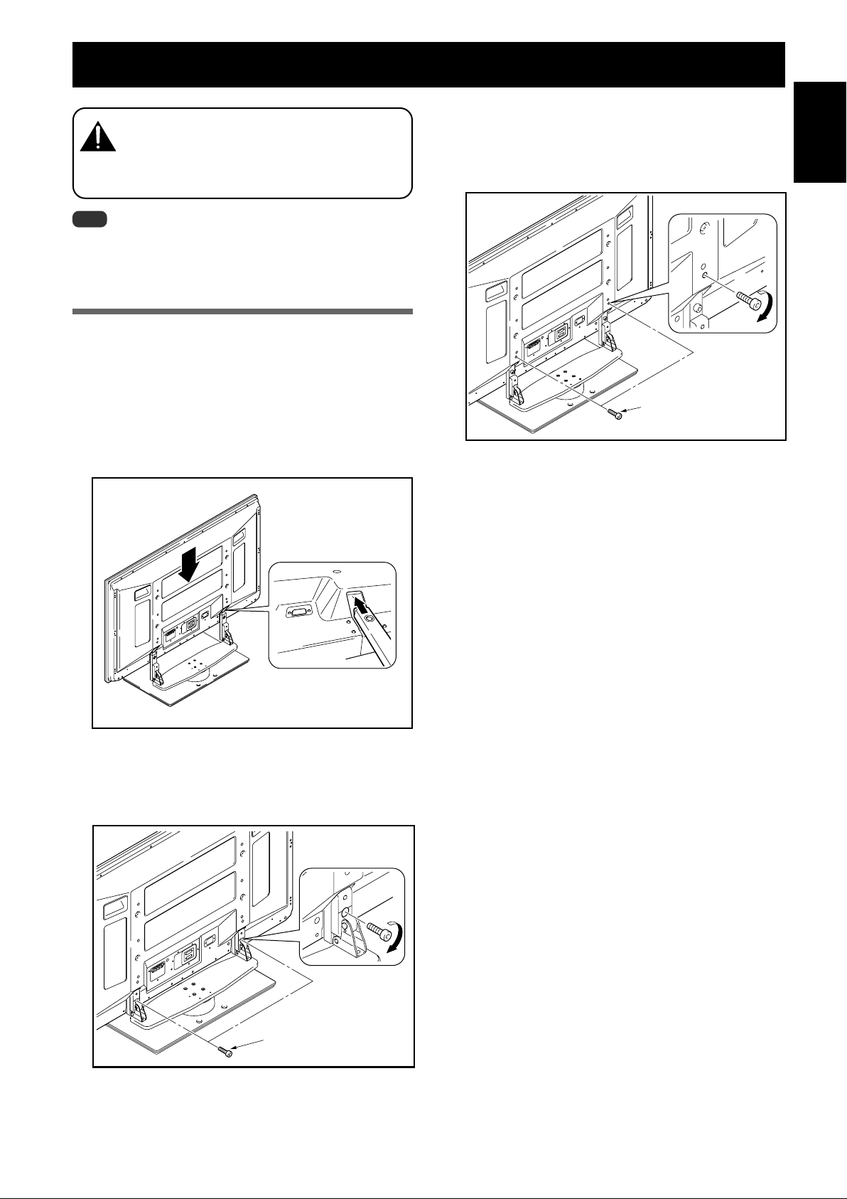
Attachment Method
1 Attaching the plasma display to the stand.
Fit the stand’s support columns to the bottom of the
plasma display as indicated by the arrows, then slowly
insert them vertically. Be extremely careful not to insert the
support columns of the stand into any part of the plasma
display other than the stand insertion slots. Note that doing
so might damage the plasma display panel or its ports or
result in the warping of the stand.
Line up the column
supports with the bottom
of the plasma display as
indicated in the accompanying diagram.
3 Securing the plasma display with
Installation screws 3.
Attach the plasma display at the points indicated by the
arrows using the enclosed hexagonal wrench.
Installation screws 3
(M8 x 40 mm: black)
4 Attaching the speakers.
Refer to the operating instructions for the speaker for
the installation method.
English
2 Securing the plasma display with
Installation screws 2.
Secure them using the enclosed hexagonal wrench.
Installation screws 2
(M8 x 30 mm: silver)
5
En
Page 6
Forward/Backward Angle of Inclination Adjustment Mechanism
On this stand, you can adjust the angle of inclination of the
Plasma Display within a range of approximately 2° forward
or backward according to your preference.
Note
Be sure to adjust the angle only after you have
attached the plasma display.
Be sure to install it on a flat table or other flat
surface.
Be sure to hold the top of the plasma display
with your hand while adjusting the angle.
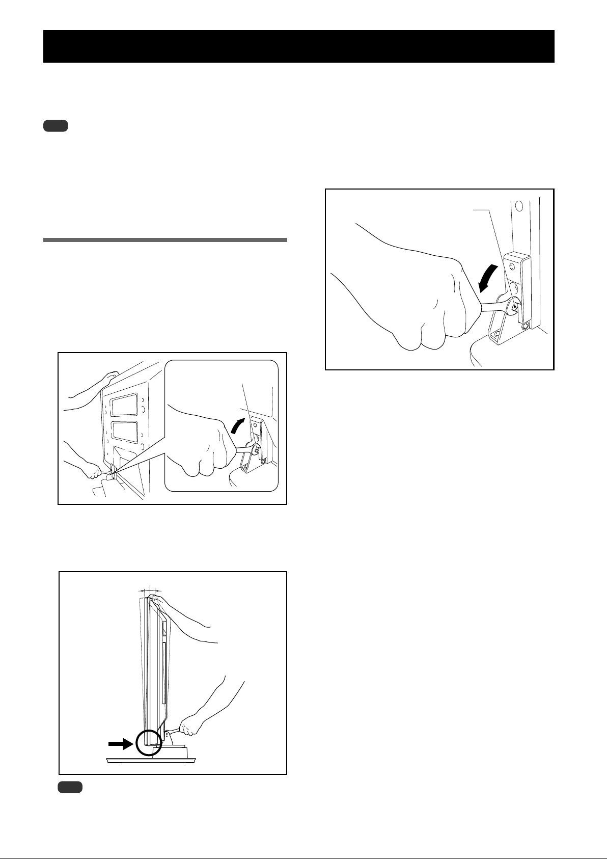
Adjustment Procedure
1 Loosen the forward/backward inclination
anchor bolts using the enclosed C wrench
(2 locations on the left and right).
While being sure to hold the top of the plasma display
with your hand, loosen the forward/backward
inclination anchor bolts on the left and right sides by
rotating them upwards using the enclosed C wrench.
Forward/backward
inclination anchor bolt
Loosening
3 Tighten the forward/backward inclination
anchor bolts (2 locations on the left and
right).
Firmly tighten the forward/backward inclination
anchor bolts on the left and right sides by rotating
them downward using the enclosed C wrench.
Be sure to hold the top of the plasma display with your
hand until you have fully tightened the bolts.
Forward/backward
inclination anchor bolt
Tightening
4 Check once more to make sure that the
forward/backward inclination anchor bolts
are fully tightened.
2 Set the angle you prefer.
Set the angle you prefer by slowly moving the plasma
display.
2˚
2˚
Note
While adjusting the angle, be very careful to keep your
hands out of the place indicated by the arrow on the figure.
6
En
Page 7

Installing the Product on a Rack etc.
Be sure to observe the following precautions when moving
or installing this product with a plasma display into a rack or
other enclosure.
Precautions when moving
When moving the product more than a few
meters, first remove the speaker, then remove
Caution
the plasma display from the stand and move the
speaker, plasma display, and stand separately.
When detaching the plasma display from the
stand, be sure to follow the procedure described
in “Detaching the Plasma Display from the
Stand” on page 10.
Precautions when installing in a rack
or other enclosure
When installing in a rack or other enclosure, hold the
plasma display by the handles located on the rear
Caution
and bottom of the plasma display. If you hold the
speakers, they may be damaged or twisted.
Installation precautions
Make sure that you always secure a space at least as large
as that shown in the following diagram in front of and
behind the table top stand.
Rack
Min. 30 mm
(1-3/16 inch)
Plasma Display
If the stand protrudes from the rack, it could cause
Caution
When rotating, take care not to allow the display
Back
Front
Table top stand
unforeseen accidents such as the equipment breaking or falling over.
to bump into walls or surrounding objects.
Min. 30 mm
(1-3/16 inch)
Min. 10 mm
(13/32 inch)
Depth of the rack
Min. 30 mm
(1-3/16 inch)
English
420 mm (16-9/16 inch)
or more recommended
Hold the plasma display by
its handles and from the
bottom.
Protrusion is dangerous.
Range of angle rotation
10˚
10˚
7
En
Page 8

Preparing the Cables
Use the enclosed cable binders to bind the cables.
Note
Be very careful not to apply force to the bases of the cables.
Using the cable binders
1 Insert the cable binder through the hole on
the top of the rotating platform of the
stand.
Cable binder
2 Gathering cables and placing them on the
cable binder.
3 Locking the cable binder.
Removing a cable binder
The lock is released by pushing
the part indicated by the arrow
in the figure.
En
8
Page 9

Preventing Equipment from Falling Over
After installing the stand, be sure to take special care to ensure that the Plasma Display will not fall over.
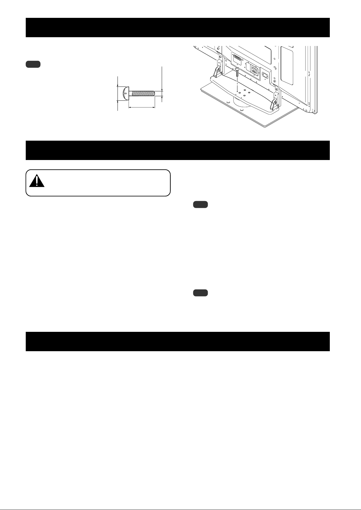
Stabilizing on table or floor
Stabilize the equipment as shown in the diagram using
screws that are available on the market.
Note
To stabilize the Plasma Display on a
table or on the floor, use screws
that have a nominal diameter of 6
mm (1/4 inch) and that are at least
20 mm (13/16 inch) long.
9 to 15 mm
Min. 20 mm
(3/8 to 5/8 inch)
(13/16 inch)
6 mm
(1/4 inch)
Using a wall for stabilization
(43 inch display model in the figure)
1 Attaching falling prevention bolts to the
Plasma Display.
2 Using strong cords or chains to stabilize it
appropriately and firmly to a wall, pillar, or
other sturdy element.
Perform this work in the same way on the left and
right sides.
The length of the cords or chains used must be long
enough to allow the stand to rotate freely.
Note
Use falling prevention bolts,
ropes, chains, and fittings that
are available on the market.
Recommended bolts:
Nominal diameter 8 mm (3/8 inch)
Length 12 to 15 mm (1/2 to 5/8 inch)
12 to 15mm
(1/2 to 5/8 inch)
8mm
English
(3/8 inch)
Caution
• A table or an area of the floor with adequate strength
should always be used to support the Plasma Display.
Failure to do so could result in personal injury and
physical damage.
• When installing the Plasma Display, please take the
necessary safety measures to prevent it from falling or
overturning in case of emergencies, such as
earthquakes, or of accidents.
• If you do not take these precautions, the Plasma
Display could fall down and cause injury.
• The screws, hooks, chains and other fittings that you
use to secure the Plasma Display to prevent it from
overturning will vary according to the composition and
thickness of the surface to which it will be attached.
• Select the appropriate screws, hooks, chains and other
fittings after first inspecting the surface carefully to
determine its thickness and composition and after
consulting a professional installer if necessary.
Position of table/floor screws: Without speakers
Unit: mm (inch)
522 (20-9/16)*
478 (18-27/32)**
120
(4-23/32)
522 (20-9/16)*
478 (18-27/32)**
2 Cord or chain
Fitting
1 Falling prevention bolts
24 (31/32)
* : 50 inch display model
** : 43 inch display model
(14-1/16)
356
9
En
Page 10
Fixing the rotation to the front
Stabilize the equipment as shown in the diagram using
screws that are available on the market.
Note
Use a screw that has a nominal
diameter of 4 mm (3/16 inch)
and length from 20 to 30 mm
(13/16 to 1-3/16 inch) to fix the
rotation to the front.
7 to 12 mm
20 to 30 mm
(5/16 to 1/2 inch)
(13/16 to 1-3/16 inch)
4 mm
(3/16 inch)
Detaching the Plasma Display from the Stand
To remove the plasma display from the stand, be sure
to always follow the procedure described below to
Caution
prevent accidents.
1 First, confirm that the forward/backward
inclination anchor bolt is securely
tightened.
2 First clear a space on a flat floor etc. where
you can lay the plasma display flat, then
lay a sheet to protect it from scratches or
other damage.
3 Remove the speakers.
Specifications
4 Referring to steps 2 and 3 in “Attaching
the Plasma Display” (Page 5.), remove the
installation screws (4 screws).
Note
Do not remove the screws (M8 x 16mm: silver) by
procedure 2 in Page 4. The support columns might slip
out of place and fall over.
5 Holding the plasma display by its handles
and from the bottom, lift the display vertically.
6 Place the plasma display slowly onto the
sheet laid out in step 2 with its screen
facing downwards.
Note
When reattaching the plasma display to the stand, be
certain that the left/right support columns are set at the
same angle.
External dimensions 577 (W) x 249.5 (H) x 380 (D) mm (22-23/32 (W) x 9-27/32 (H) x 14-31/32 (D) in.)
[When using the support columns]
Weight 10.5 kg (23.2 lbs)
• The above specifications and exterior may be modified without prior notice to improve the product.
10
En
Page 11

Dimensions Diagram
Unit: mm (inch)
When installing the PDP-S35 or the PDP-S36 speakers
English
1407 (55-13/32) [50 inch display model] *
1379 (54-5/16) [50 inch display model] *
1259 (49-19/32) [43 inch display model] *
1231 (48-15/32) [43 inch display model] *
717 (28-1/4) [50 inch display model]
632 (24-29/32) [43 inch display model]
577 (22-23/32)
*1 Air installation: Attached with a space of approximately 15 mm between the speakers and the display.
*2 Flush installation: Attached with the speakers in close contact with the display.
1
2
1
2
80
(3-5/32)
140
(5-17/32)
791 (31-5/32) [50 inch display model]
706 (27-13/16) [43 inch display model]
125.1
(4-15/16)
380 (14-31/32)
92
(3-5/8)
23
(29/32)
162.9
(6-7/16)
Without speakers
717 (28-1/4) [50 inch display model]
632 (24-29/32) [43 inch display model]
1224 (48-7/32) [50 inch display model]
1076 (42-3/8) [43 inch display model]
577 (22-23/32)
80
(3-5/32)
140
(5-17/32)
*791 (31-5/32) [50 inch display model]
*706 (27-13/16) [43 inch display model]
125.1
(4-15/16)
380 (14-31/32)
92
(3-5/8)
23
(29/32)
162.9
(6-7/16)
Published by Pioneer Corporation.
Copyright © 2005 Pioneer Corporation.
All rights reserved.
11
En
Page 12

Nous vous remercions d’avoir choisi un produit Pioneer. Veuillez
lire attentivement ce mode d’emploi pour savoir comment utiliser
correctement et en toute sécurité votre support. Nous vous
conseillons de conserver soigneusement ce mode d’emploi à
proximité et dans un endroit sûr afin de pouvoir vous y référer le
cas échéant.
AVIS IMPORTANT – VEUILLEZ REPORTER CI-DESSOUS LES
NUMEROS DE MODELE ET DE SERIE DE L’EQUIPEMENT.
CES NUMEROS APPARAISSENT A L’ARRIERE.
Nº MODELE :
Nº SERIE :
VEUILLEZ CONSERVER CES NUMEROS EN VUE DE
FUTURES UTILISATIONS.
Installation
¶ En cas de difficultés, veuillez consulter votre revendeur.
¶ Pioneer ne saura être tenu responsable d’aucun
dommage résultant d’une installation ou d’une
utilisation incorrecte de ce produit, de sa modification
ou encore de catastrophes naturelles.
Table des matières
Attention .......................................................................... 12
Vérification des pièces contenues dans le carton
d’emballage ..................................................................... 13
Assemblage du support ................................................. 14
Installation et fixation de l’écran à plasma................... 15
Mécanisme d’ajustement de l’angle d’inclinaison en
avant et en arrière ........................................................... 16
Installation du produit sur une étagère, etc. ................ 17
Préparation des câbles ................................................... 18
Prévenir le basculement et la chute de l’équipement ... 19
Fixation de la rotation à l’avant ..................................... 20
Démontage de l’écran à plasma du support ................ 20
Spécificités....................................................................... 20
Schéma indiquant les dimensions ................................ 21
Attention
Ce produit est un support conçu exclusivement pour les écrans à
plasma Pioneer (PRO-1130HD / PRO-930HD).
L’utilisation de ce produit avec un autre modèle peut être à
l’origine d’un manque de stabilité pouvant entraîner une blessure.
Pour de plus amples informations, veuillez contacter le magasin
où vous avez acheté votre écran.
N’installez pas le produit d’une manière autre que celle qui est
spécifiée ni le modifier. En outre, n’utilisez pas ce support pour un
écran à plasma autre que ceux pour lesquels il a été conçu et ne le
modifiez pas ou ne l’utilisez pas à des fins autres que celles pour
lesquelles il a été conçu.
Une installation incorrecte est extrêmement dangereuse car elle
peut provoquer la chute du support ou un autre accident.
Lieu d’installation
• Sélectionnez un emplacement assez solide pour supporter le
poids du support et de l’écran.
• Assurez-vous de placer le produit à un emplacement stable et
plat.
• N’installez pas le support à l’extérieur, à proximité d’une source
thermale ou sur une plage.
• N’installez pas le support à un endroit où il pourrait être soumis
à des chocs ou à des vibrations.
Montage et installation
• Montez le support en suivant les instructions et vissez
solidement toutes les vis aux endroits prévus à cet effet.
Des accidents ont été constatés (casse, chute du matériel,
etc.) après l’installation de l’écran parce que le support
n’avait pas été installé conformément aux instructions.
• Pour une bonne installation, l’écran doit toujours être
installé par au moins deux personnes.
• Avant de procéder à l’installation, mettez l’écran ainsi que
les équipements périphériques hors tension en coupant
l’alimentation, puis retirer la prise du câble d’alimentation
de la prise murale.
Ce produit pivote de 10° vers la gauche et la droite et s’incline de
2° environ en avant et en arrière.
Veillez à ne pas placer d’objets à l’intérieur du champ de rotation
de telle sorte que durant l’utilisation habituelle ou la rotation du
produit, rien ne dépasse de l’étagère ou de l’emplacement sur
lequel il a été installé. Sans cela, des accidents pourraient survenir,
entraînant la détérioration de l’appareil ou sa chute (Voir page 17).
Lorsque vous ajustez l’angle vers l’avant et vers l’arrière, faites
extrêmement attention à ne pas placer vos mains entre le bas de
l’écran à plasma et le support (Voir page 16).
ATTENTION
Ce symbole indique un danger ou une pratique
dangereuse susceptible de provoquer des dommages
corporels ou matériels.
12
Fr
Il convient de prévenir les accidents causés par la chute du
produit, en cas de tremblement de terre ou autres, en prenant des
mesures fiables pour éviter toute chute (Voir page 19).
Page 13

Vérification des pièces contenues dans le carton d’emballage
Cette vérification vous permettra de vous assurer que vous possédez bien toutes les pièces nécessaires avant de procéder au montage et
à l’installation du support.
Support de couverture de table x 1 unité
Colonnes de support x 2 unités
Serre-câbles x 2 unités
Vis d’installation 1 (M8 x 16 mm : argentée) x 4 unités
[Utilisées pour fixer les colonnes de support et le support de
couverture de table]
Vis d’installation
2
(M8 x 30 mm : argentée) x 2 unités
Clé hexagonale (à six pans) x 1 unité
(Taille en diagonale : 6 mm)
Vis d’installation
(M8 x 40 mm : noir) x 2 unités
Mode d’emploi
(ce document) x 1 exemplaire
Table top stand
Support de couverture de table
Soporte de mesa
PDK-1013
Français
3
Clé hexagonale x 1 unité
(10 mm)
Operating instructions
Mode d’emploi
Manual de instrucciones
13
Fr
Page 14

Assemblage du support
Remarques
Pour monter le support, travaillez toujours sur une surface plane.
Introduisez les vis à la verticale et ne les serrez pas plus que
nécessaire.
Procédure de montage
1 Fixez les colonnes sur le support à l’aide des vis
d’installation 1 (2 sur le côté gauche et 2 sur le
côté droit).
A l’aide de la clé hexagonale fournie, vissez légèrement les vis
en commençant par celle du haut.
Les orifices les plus larges
se trouvent à l’avant.
Vis d’installation
(M8 x 16 mm : argentée)
1
2 Vissez à fond les vis d’installation (2 sur le côté
gauche et 2 sur le côté droit).
Vissez à fond les vis d’installation.
Remarques
Veillez à bien ranger les colonnes de support non utilisées, la clé
hexagonale, la clé C et le mode d’emploi au même endroit.
14
Fr
Page 15

Installation et fixation de l’écran à plasma
Le poids d’un écran à plasma 50 pouces (seul sans les
haut-parleurs) est de 32 kg environ et celui d’un modèle
Attention
Remarques
Montez toujours l’écran à plasma sur une surface plane et stable.
Introduisez les vis à la verticale et ne les serrez pas plus que
43 pouces (seul sans les haut-parleurs) de 26 kg environ.
Leur largeur étant limitée, ils ne sont pas stables. Par
conséquent, ils doivent toujours être installés par deux
personnes à la fois.
nécessaire.
Méthode de fixation
1 Installation de l’écran à plasma sur le support.
Mettez les colonnes de soutien en place au bas de l’écran à
plasma comme indiqué par les flèches, puis insérez-les
lentement à la verticale. Veillez à ne pas insérer les colonnes
ailleurs que dans les fentes prévues à cet effet. Cela risquerait
d’endommager l’écran, ses ports ou encore le support.
Alignez les colonnes du
support sur la partie inférieure
de l’écran comme indiqué sur
le schéma ci-joint.
3 Fixez solidement l’écran à plasma avec les vis
3
d’installation
Fixez l’écran à plasma aux endroits indiqués par les flèches à
l’aide de la vis hexagonale fournie.
.
Vis d’installation
(M8 x 40 mm : noir)
3
4 Mise en place des haut-parleurs.
Pour la méthode d’installation, reportez-vous au mode
d’emploi des haut-parleurs.
Français
2 Fixez solidement l’écran à plasma avec les vis
2
d’installation
Vissez solidement celles-ci au moyen de la clé hexagonale
fournie avec le support.
.
Vis d’installation
(M8 x 30 mm : argentée)
2
15
Fr
Page 16

Mécanisme d’ajustement de l’angle d’inclinaison en avant et en arrière
Lors de cette étape, vous pouvez choisir de régler l’angle
d’inclinaison de l’écran à plasma de 2° environ en avant ou en
arrière.
Remarques
Veuillez ajuster l’angle uniquement après avoir fixé
l’écran à plasma.
Assurez-vous de l’installer sur une table plane ou
toute autre surface plane.
Assurez-vous de tenir le haut de l’écran à plasma
entre vos mains lorsque vous ajustez l’angle.
Procédure d’ajustement
1 Desserrez les boulons d’ancrage servant à
régler l’inclinaison en avant et en arrière à
l’aide de la clé hexagonale fournie
(2 emplacements à gauche et à droite).
En vous assurant de tenir le haut de l’écran à plasma entre
vos mains, desserrez les boulons d’ancrage servant à régler
l’inclinaison en avant et en arrière, sur le côté gauche et sur
le côté droit, en les tournant vers le haut à l’aide de la clé
hexagonale fournie.
3 Serrez les boulons d’ancrage servant à régler
l’inclinaison en avant et en arrière
(2 emplacements à gauche et à droite).
Serrez fermement les boulons d’ancrage servant à régler
l’inclinaison en avant et en arrière, sur le côté gauche et sur
le côté droit, en les tournant vers le bas à l’aide de la clé
hexagonale fournie. Assurez-vous de tenir le haut de l’écran à
plasma entre vos mains jusqu’à ce que les boulons soient
complètement serrés.
Boulons d’ancrage servant à régler
l’inclinaison en avant et en arrière
Resserrement
Boulons d’ancrage servant à régler
l’inclinaison en avant et en arrière
Desserrement
2 Choisissez l’angle que vous préférez.
Choisissez l’angle que vous préférez en manipulant
doucement l’écran à plasma.
2˚
2˚
4 Vérifiez une fois de plus que les boulons
d’ancrage servant à régler l’inclinaison en avant
et en arrière sont complètement serrés.
Remarque
Lorsque vous ajustez l’angle, faites bien attention à ne pas placer
vos mains à l’endroit indiqué par un cercle sur le schéma.
16
Fr
Page 17

Installation du produit sur une étagère, etc.
Les précautions suivantes doivent être strictement observées
lorsque vous déplacez ou installez le produit avec un écran à
plasma sur une étagère ou dans un espace limité.
Précautions à respecter lors du
déplacement du produit
Avant de déplacer l’appareil sur plusieurs mètres,
démontez les haut-parleurs. Séparez également l’écran
Attention
à plasma de son support et transportez chaque partie
séparément.
Lorsque vous démontez l’écran à plasma du support,
assurez-vous de suivre la procédure décrite dans la
partie « Démontage de l’écran à plasma du support » à
la page 20.
Précautions à respecter en cas d’installation
de l’appareil sur une étagère ou à tout autre
endroit où l’espace est restreint
Lors de l’installation de l’appareil sur une étagère ou dans
endroit exigu, tenez l’écran à plasma par les poignées à
Attention
l’arrière et par le fond. Si vous le soulevez par les hautparleurs, ces derniers risqueraient d’être endommagés ou
de se tordre.
Précautions d’installation
Veillez à toujours ménager devant et derrière le support un espace
au moins égal à celui qui est indiqué sur le schéma ci-dessous.
30 mm mini 30 mm mini
Support de cauverture de table
Ecran à plasma
Tout dépassement de l’étagère risquerait de provoquer
la détérioration ou la chute de l’appareil.
Attention
Lors des rotations du support, veillez à ce que l’écran
n’entre pas en contact avec le mur ou avec les autres
objets environnants.
Etagère
Arrière
Avant
10 mm mini
Profondeur de l’étagère
30 mm mini
Nous recommandons 420 mm
au minimum.
Français
Tenez l’écran à plasma par ses
poignées et par le fond.
Tout dépassement est
dangereux.
Fourchette de l’angle de rotation
10˚
10˚
17
Fr
Page 18

Préparation des câbles
Utilisez les serre-câbles pour regrouper les câbles.
Remarque
Veillez à ne pas forcer la base des câbles.
Utilisation des serre-câbles
1
Insérez le serre-câble dans les orifices se
trouvant au-dessus de la plate-forme pivotante
du support.
Serre-câbles
2
Rassemblez les câbles et placez-les dans le
serre-câble.
3
Fermez le serre-câble.
Retrait d’un serre-câble
Le système de fermeture est débloqué
en appuyant sur la zone indiquée par le
cercle sur la figure.
18
Fr
Page 19

Prévenir le basculement et la chute de l’équipement
Après avoir installé le support, veillez à prendre les précautions nécessaires pour que l’écran à plasma ne tombe pas.
Position de fixation sur une table ou au sol
Stabilisez le support comme indiqué sur le schéma à l’aide de vis
vendues dans le commerce.
Remarque
Afin de stabiliser l’écran à plasma
sur une table ou au sol, utilisez des
vis de 6 mm de diamètre nominal et
d’au moins 20 mm de long.
Attention
9 à 15 mm
20 mm mini
6 mm
Utilisation d’un mur pour stabiliser le support
(Modèle d’écran 43 pouces comme indiqué sur la figure)
1
Fixation des boulons empêchant la chute sur
l’écran à plasma.
2
Utilisation de câbles solides ou de chaînes pour
stabiliser solidement le dispositif sur un mur,
un pilier ou d’autres éléments stables.
Ces opérations doivent être effectuées de la même
manière à gauche et à droite.
La longueur des câbles ou des chaînes utilisés doit être
suffisante pour permettre au support de tourner librement
sur sa base.
Remarque
Utilisez des boulons, des cordons, des
chaînes ou d’autres dispositifs de
fixation en vente dans le commerce.
Boulons recommandés : Diamètre nominal 8 mm,
longueur de 12 à 15 mm.
12 à 15 mm
8mm
Français
• Choisissez toujours une table ou une portion du sol avec une
force suffisante pour supporter l’écran à plasma. Il en
résulterait autrement des blessures corporelles et des
dégâts physiques.
• Lors de l’installation de l’écran à plasma, veuillez prendre les
mesures de sécurité nécessaires pour l’empêcher de
tomber ou de basculer en cas de sinistres comme un
tremblement de terre ou un accident.
• Le cas contraire, l’écran à plasma pourrait tomber et
provoquer des dégâts.
• Les vis, crochets, chaînes et autres raccords que vous
utilisez pour fixer en place l’écran à plasma afin de
l’empêcher de basculer dépendront de la composition et de
l’épaisseur de la surface sur laquelle vous le fixez.
• Choisissez les vis, crochets, chaînes et autres raccords
appropriés après avoir tout d’abord soigneusement
inspecter la surface pour déterminer sa composition et son
épaisseur et après avoir pris contact avec un installateur
professionnel si besoin est.
Position des vis de fixation à la table et au sol : sans les
haut-parleurs
Unité : mm
522 (Ecran d'affichage 50 pouces)
478 (Ecran d'affichage 43 pouces)
522 (Ecran d'affichage 50 pouces)
478 (Ecran d'affichage 43 pouces)
120
24
2 Câble ou chaîne
Attache
1
Vis de prévention de chutes
356
19
Fr
Page 20

Fixation de la rotation à l’avant
Stabilisez le support comme indiqué sur le schéma à l’aide de vis
vendues dans le commerce.
Remarque
utilisez une vis de 4 mm de diamètre et
longue de 20 à 30 mm afin de fixer la
rotation à l’avant.
7 à 12 mm
20 à 30 mm
4 mm
Démontage de l’écran à plasma du support
Lorsque vous démontez l’écran à plasma de son support,
observez strictement la procédure indiquée ci-dessous afin
Attention
d’éviter les accidents.
1 Assurez-vous d’abord que les boulons
d’ancrage servant à l’inclinaison en avant et en
arrière sont serrés correctement.
2 Faites d’abord de la place sur une surface
plane, etc. où vous pouvez laisser l’écran à
plasma à plat, puis déposez une feuille afin de
le protéger des rayures et autres dégâts
éventuels.
3 Retirez les haut-parleurs.
4
En vous référant aux opérations 2 et 3 décrites
dans le chapitre Installation et fixation de
l’écran à plasma (page 15), retirez les 4 vis.
Note
Ne retirez pas les boulons (M8 x 16 mm) argentés (voir étape 2
page 14), sinon les colonnes de support risquent de bouger de
place et de tomber.
5 Tout en le tenant par ses poignées et par le
fond, placez l’écran à la verticale.
6 Placez l’écran à plasma avec soin sur la feuille
citée lors de l’étape 2, l’écran regardant vers le
bas.
Remarque
lorsque vous remontez l’écran à plasma sur le support, assurezvous d’installer les colonnes de support de gauche et de droite
en respectant le même angle.
Spécificités
Dimensions extérieures : 577 (largeur) x 249,5 (hauteur) x 380 (profondeur) mm (en cas d’utilisation de colonnes de support)
Poids : 10,5 kg
• Les caractéristiques techniques indiquées ci-dessus ainsi que les dimensions extérieures peuvent êtres modifiées sans avis préalable en
vue d’améliorer le produit.
20
Fr
Page 21

Schéma indiquant les dimensions
Unité : mm
Installation des haut-parleurs PDP-S35 et le PDP-S36
1407 [Ecran d'affichage 50 pouces] *
1379 [Ecran d'affichage 50 pouces] *
1259 [Ecran d'affichage 43 pouces] *
1231 [Ecran d'affichage 43 pouces] *
717 [Ecran d'affichage 50 pouces]
632 [Ecran d'affichage 43 pouces]
577
*1 Montage pivotant : fixées à une distance de 15 mm environ entre les haut-parleurs et l’écran.
*2 Montage à ras : fixées avec les haut-parleurs près de l’écran.
1
2
1
2
125,1
80
791 [Ecran d'affichage 50 pouces]
706 [Ecran d'affichage 43 pouces]
140
92
23
Français
162,9
380
Sans les haut-parleurs
1224 [Ecran d'affichage 50 pouces]
1076 [Ecran d'affichage 43 pouces]
717 [Ecran d'affichage 50 pouces]
632 [Ecran d'affichage 43 pouces]
577
80
*791 [Ecran d'affichage 50 pouces]
*706 [Ecran d'affichage 43 pouces]
140
92
23
125,1
162,9
380
Publication de Pioneer Corporation.
© 2005 Pioneer Corporation.
Tous droits de reproduction et de traduction réservés.
21
Fr
Page 22

Gracias por comprar un producto Pioneer.
Por favor, lea atentamente el Manual de instrucciones para saber
cómo utilizar este modelo de una forma segura y correcta.
Le recomendamos que conserve el Manual de instrucciones para
consultarlo en el futuro.
AVISO IMPORTANTE – ANOTE MÁS ABAJO EL NÚMERO
DE MODELO Y EL NÚMERO DE SERIE DE ESTE EQUIPO.
LOS ENCONTRARÁ DETALLADOS EN LA PARTE
POSTERIOR DEL MISMO.
N.º DE MODELO
N.º DE SERIE
GUARDE ESTOS NÚMEROS PARA FUTURAS
Precauciones
Este producto es un soporte de mesa diseñado exclusivamente
para pantallas de plasma (PRO-1130HD / PRO-930HD) de Pioneer.
Su empleo con otros modelos podría provocar la inestabilidad del
producto, con el consiguiente riesgo de lesiones. Si desea más
información, póngase en contacto con el establecimiento en el
que compró su pantalla.
No instale ni modifique el producto de una forma distinta a la
especificada.
No utilice este soporte para una pantalla de plasma diferente de
las indicadas, y no lo modifique ni lo utilice para otros fines.
Instalación
¶ Si encuentra dificultades para la instalación, consulte a su
distribuidor.
Pioneer no es responsable de ningún daño que pueda
derivarse de una instalación o uso inapropiados,
modificaciones o desastres naturales.
Índice
Precauciones.................................................................... 22
Comprobación de las piezas incluidas .......................... 23
Montaje del soporte ........................................................ 24
Montaje de la pantalla de plasma ................................. 25
Mecanismo de ajuste del ángulo de inclinación
delantera y posterior ............................................................
Instalación del producto en un bastidor o similar ....... 27
Preparación de los cables ............................................... 28
Cómo evitar que el equipo se caiga .............................. 29
Cómo fijar la rotación en la parte delantera ................. 30
Desmontaje de la pantalla de plasma del soporte ...... 30
Especificaciones .............................................................. 30
Diagrama de dimensiones.............................................. 31
PRECAUCIÓN
Este símbolo indica un riesgo o práctica insegura que puede
tener como resultado daños personales o materiales.
26
Es muy peligroso realizar una instalación inadecuada, ya que
puede tener como resultado la caída de la pantalla o accidentes de
otro tipo.
Lugar de instalación
• Elija un lugar lo suficientemente resistente como para aguantar
el peso del soporte y la pantalla.
• Asegúrese de que el lugar de instalación sea una superficie
llana y estable.
• No instale el soporte en el exterior ni en lugares con agua,
como una fuente termal o cerca de una playa.
• No instale el soporte donde pueda sufrir vibraciones o golpes.
Montaje e instalación
• Monte el soporte de acuerdo con las instrucciones de
montaje y atornille de forma segura todos los tornillos en
los lugares indicados.
Ha habido casos de accidentes imprevistos, como la rotura
o caída del equipo después de la instalación de la pantalla,
porque el soporte no se había instalado de acuerdo con las
instrucciones.
• Para garantizar una instalación segura de la pantalla , es
necesario que siempre lo hagan dos o más personas.
• Antes de la instalación, apague la pantalla y los
dispositivos periféricos y desenchufe el cable de
alimentación de la toma eléctrica.
Este producto gira 10° a derecha e izquierda, y se inclina unos 2°
hacia delante y hacia atrás.
No coloque objetos en la zona de rotación de este producto y de la
pantalla de plasma. Instale este producto de tal forma que durante
su uso normal o cuando se gire no sobresalga del bastidor o del
lugar en el que lo haya montado. Si no lo hace así, es posible que
se produzcan accidentes imprevistos, como la rotura o caída del
equipo (consulte la página 27).
Cuando ajuste el ángulo hacia delante o hacia atrás, tenga
muchísimo cuidado de no colocar las manos entre la parte inferior
de la pantalla de plasma y el soporte (consulte la página 26).
Para evitar accidentes causados por la caída del producto durante,
por ejemplo, un terremoto, tome todas las medidas necesarias
para impedir que el equipo pueda caerse (consulte la página 29).
22
Sp
Page 23

Comprobación de las piezas incluidas
Antes de proceder al montaje e instalación, asegúrese de tener todas las piezas incluidas.
Soporte de mesa x 1
Columnas de soporte x 2
Tornillos de instalación
1
(M8 x 16 mm: plateados) x 4
[utilizados para anclar las columnas y el soporte de mesa]
Tornillos de instalación
(M8 x 30 mm: plateados) x 2
Llave Allen x 1
[tamaño diagonal: 6 mm)
2
Tornillos de instalación
(M8 x 40 mm: negros) x 2
Manual de instrucciones
(este documento) x 1
Table top stand
Support de couverture de table
Soporte de mesa
PDK-1013
3
Español
Bridas para cables x 2
Llave de maquinista x 1
(10 mm)
Operating instructions
Mode d’emploi
Manual de instrucciones
23
Sp
Page 24

Montaje del soporte
Nota
Móntelo siempre en una mesa plana o similar.
Introduzca los tornillos verticalmente en los agujeros y no los
apriete más de lo necesario.
Procedimiento de montaje
1 Asegure la columna en el soporte mediante los
tornillos de instalación 1 (4 posiciones a la
derecha e izquierda).
Utilice la llave Allen suministrada para primero apretar
ligeramente el tornillo de acoplamiento superior y, a
continuación, el tornillo de acoplamiento inferior.
Los agujeros más
grandes están en la
parte delantera.
Tornillos de instalación
(M8 x 16 mm: plateados)
1
2 Apriete completamente los tornillos de
instalación (4 posiciones a la derecha e
izquierda).
Apriete completamente los tornillos de acoplamiento.
Nota
Guarde en un mismo lugar las columnas de soporte no utilizadas,
la llave Allen, la llave de maquinista y el Manual de instrucciones.
24
Sp
Page 25

Montaje de la pantalla de plasma
Una pantalla de plasma de 50 pulgadas (sin altavoces)
pesa alrededor de 32 kg; una de 43 pulgadas (sin
PRECAUCIÓN
Nota
Asegúrese de que la instala en un lugar estable.
Introduzca los tornillos verticalmente en los agujeros y no los
apriete más de lo necesario.
altavoces), alrededor de 26 kg; al no tener fondo, son
inestables. Por lo tanto, es necesario que al menos dos
personas intervengan en su montaje e instalación.
Método de fijación
1 Montaje de la pantalla de plasma en el soporte.
Coloque las columnas del soporte debajo de la pantalla de
plasma, tal y como indican las flechas. Después, introdúzcalas
lentamente de forma vertical. Tenga muchísimo cuidado de no
insertar las columnas del soporte en ningún otro lugar de la
pantalla de plasma que no sean las ranuras de inserción del
soporte. Tenga en cuenta que si eso ocurriera, se podrían
producir daños en el panel de la pantalla de plasma o sus
puertos, o deformaciones en el soporte.
Alinee los soportes de las
columnas con la parte
inferior de la pantalla de
plasma, tal como se indica en
la figura que sigue.
3 Fijación de la pantalla de plasma con los
3
Tornillos de instalación
Con la ayuda de la llave Allen suministrada, asegure la pantalla
de plasma en los puntos indicados por las flechas.
.
Tornillos de instalación
(M8 x 40 mm: negros)
3
4 Montaje de los altavoces.
Consulte el método de instalación en el Manual de
instrucciones de los altavoces.
Español
2 Fijación de la pantalla de plasma con los
2
tornillos de instalación
Apriételos con la llave Allen que se incluye con el soporte.
.
Tornillos de instalación
(M8 x 30 mm: plateados)
2
25
Sp
Page 26

Mecanismo de ajuste del ángulo de inclinación delantera y posterior
Este soporte le permite ajustar el ángulo de inclinación de la
pantalla de plasma, hacia delante o hacia atrás, hasta un máximo
de 2° aproximadamente, según sus preferencias.
Nota
Recuerde que sólo deberá ajustar el ángulo una vez
que haya instalado la pantalla de plasma.
Asegúrese de realizar la instalación sobre una mesa
plana u otra superficie llana.
Cuando ajuste el ángulo, no se olvide de sujetar con
la mano la parte superior de la pantalla de plasma.
Procedimiento de ajuste
1 Utilice la llave de maquinista suministrada para
aflojar los pernos de anclaje que permiten la
inclinación delantera y posterior de la pantalla
(2 posiciones a la derecha e izquierda).
Sujete con la mano la parte superior de la pantalla de plasma y
proceda a aflojar los pernos de anclaje que permiten la
inclinación delantera y posterior, situados en el lado
derecho e izquierdo, haciéndolos girar hacia arriba con llave de
maquinista suministrada.
3 Apriete los pernos de anclaje que permiten la
inclinación delantera y posterior (2 posiciones a
la derecha e izquierda).
Apriete firmemente los pernos de anclaje que permiten la
inclinación delantera y posterior, situados en el lado
derecho e izquierdo, haciéndolos girar hacia abajo mediante la
llave de maquinista suministrada. Recuerde sujetar con la
mano la parte superior de la pantalla de plasma hasta que haya
terminado de apretar por completo todos los pernos.
Perno de anclaje que permite la
inclinación delantera y posterior
Apretar
Perno de anclaje que permite la
inclinación delantera y posterior
Aflojar
2 Determine el ángulo que usted prefiera.
Determine el ángulo que usted prefiera moviendo lentamente
la pantalla de plasma.
2˚
2˚
4 Compruebe una vez más que los pernos de
anclaje que permiten la inclinación delantera y
posterior están bien apretados.
26
Sp
Nota
Cuando esté ajustando el ángulo, tenga mucho cuidado de no
colocar las manos en el lugar indicado por la flecha de la figura.
Page 27

Instalación del producto en un bastidor o similar
Asegúrese de que respeta las siguientes precauciones al
desplazar o instalar este producto con una pantalla de plasma en
un bastidor o similar.
Precauciones para el desplazamiento
Si va a desplazar el producto a más de unos pocos
metros, desmonte primero los altavoces, después
PRECAUCIÓN
desmonte la pantalla de plasma del soporte y lleve
los altavoces, la pantalla de plasma y el soporte por
separado a su nueva ubicación.
Cuando vaya a desmontar la pantalla del plasma
del soporte, asegúrese de seguir el procedimiento
descrito en la página 30: “Desmontaje de la
pantalla de plasma del soporte.”
Precauciones para instalar en un bastidor
o similar
Si la va a instalar en un bastidor o similar, sujete la
pantalla por las asas que hay en la parte posterior y
PRECAUCIÓN
por debajo de la pantalla de plasma. Si la sujeta por
los altavoces, puede dañarlos o doblarlos.
Precauciones para la instalación
Asegúrese de dejar siempre libre delante y detrás del soporte un
espacio de la medida indicada en la siguiente figura, como
mínimo.
Bastidor
Mín. 30 mm
Soporte de mesa
Pantalla de plasma
Si el soporte sobresale del bastidor, podría
provocar accidentes imprevistos, como la rotura o
PRECAUCIÓN
caída del equipo.
Al girarla, tenga cuidado de que la pantalla no
choque contra las paredes o los objetos de
alrededor.
Parte trasera
Parte delantera
Mín. 30 mm
Mín. 10 mm
Fondo del bastidor
Mín. 30 mm
Recomendable 420 mm
como mínimo
Español
Sujete la pantalla de plasma
por las asas y por la parte
inferior.
Es peligroso que sobresalga.
Rango de rotación del ángulo
10˚
10˚
27
Sp
Page 28

Preparación de los cables
Para sujetar los cables, utilice las bridas para cables que se
incluyen con el soporte.
Nota
Tenga mucho cuidado de no ejercer fuerza en la base de los cables.
Uso de las bridas para cables
1
Pase la brida para cables por el agujero situado
en la parte superior de la plataforma giratoria
del soporte.
Brida para cables
2
Reúna los cables y colóquelos sobre la brida
para cables.
3
Cierre la brida para cables.
Cómo retirar una brida para cables
Para abrir la brida, presione la parte
indicada por la flecha de la figura.
28
Sp
Page 29

Cómo evitar que el equipo se caiga
Después de instalar el soporte, asegúrese de que toma las medidas necesarias para que la pantalla de plasma no
se caiga.
Estabilización sobre una base o el suelo
Estabilice el equipo de la forma que se muestra en la figura
utilizando tornillos disponibles en el mercado.
Nota
Para estabilizar la pantalla de plasma
sobre una base o el suelo, utilice
tornillos con un diámetro nominal de 6
mm y una longitud mínima de 20 mm.
Mín. 20 mm
De 9 a 15 mm
6 mm
Utilización de una pared para estabilizar la
pantalla
(en la figura se muestra un modelo de pantalla de 43
pulgadas)
1
Fije pernos a la pantalla de plasma para evitar
su caída.
2
Utilice cuerdas fuertes o cadenas para
estabilizarla adecuadamente y de forma segura
a una pared, columna u otro elemento
resistente.
Realice este procedimiento de la misma forma en el lado
derecho e izquierdo.
La longitud de las cuerdas o cadenas deberá ser lo
suficientemente larga para permitir que el soporte gire
libremente.
Nota
Utilice pernos anticaída, cadenas y
fijaciones disponibles en el
mercado.
Pernos recomendados: Diámetro nominal: 8 mm
Longitud: De 12 a 15 mm
De 12 a 15 mm
8 mm
Español
PRECAUCIÓN
• Para apoyar la pantalla de plasma siempre debe utilizarse
una mesa o un área del piso con la resistencia adecuada.
De no ser así se podrían causar lesiones personales y daños
físicos.
• Al instalar la pantalla de plasma, adopte las medidas de
seguridad necesarias para evitar que la misma se caiga o se
vuelque en caso de emergencias, como terremotos, o de
accidentes.
• Si no adopta estas precauciones, la pantalla de plasma
puede caerse y causar lesiones.
• Los tornillos, alcayatas, cadenas y otros accesorios que
utilice para asegurar la pantalla de plasma e impedir que se
vuelque variarán de acuerdo con la composición y el
espesor de la superficie a la cual se fijará.
• Seleccione los tornillos, alcayatas, cadenas y otros
accesorios adecuados después de haber inspeccionado
detenidamente la superficie para determinar su
composición y su espesor y de haber consultado con un
instalador profesional en caso de ser necesario.
Posición de los tornillos asegurados en una base o en el
suelo: sin altavoces
Unidad: mm
522 (modelo de pantalla de 50 pulgadas)
478 (modelo de pantalla de 43 pulgadas)
522 (modelo de pantalla de 50 pulgadas)
478 (modelo de pantalla de 43 pulgadas)
120
2 Cuerda o cadena
Fijación
1
Pernos anticaída
24
356
29
Sp
Page 30

Cómo fijar la rotación en la parte delantera
Estabilice el equipo de la forma que se muestra en la figura
utilizando tornillos disponibles en el mercado.
Nota
Para fijar la rotación en la parte delantera,
utilice un tornillo cuyo diámetro nominal
sea de 4 mm y cuya longitud esté
comprendida entre los 20 y 30 mm.
De 7 a 12 mm
De 20 a 30 mm
4 mm
Desmontaje de la pantalla de plasma del soporte
Para evitar accidentes, siga siempre el procedimiento
descrito a continuación para desmontar la pantalla de
PRECAUCIÓN
plasma del soporte.
1 Primero, asegúrese de que el perno de anclaje
que permite la inclinación delantera y posterior
de la pantalla está bien apretado.
2 Primero, despeje un espacio sobre un suelo
plano en el que pueda colocar tumbada la
pantalla de plasma; después, cubra el espacio
así despejado con una sábana para proteger la
pantalla de arañazos u otros daños.
3 Desmonte los altavoces.
Especificaciones
4
Consulte los pasos 2 y 3 de “Montaje de la
pantalla de plasma” (página 25) para quitar los
tornillos de instalación (4 tornillos).
Note
No extraiga los tornillos (M8 x 16 mm: plateados) utilizados en
el paso 2 de la página 24. Las columnas de soporte podrían
salirse de su sitio y caerse.
5 Mientras sujeta la pantalla de plasma por las
asas y por la parte inferior, deslícela hacia
arriba.
6 Coloque lentamente la pantalla de plasma
sobre la sábana extendida, según lo indicado
en el paso 2, con la cara de la pantalla mirando
hacia abajo.
Nota
Cuando vuelva a instalar la pantalla de plasma en el soporte,
asegúrese de que las columnas de soporte de la izquierda y la
derecha estén colocadas en el mismo ángulo.
Dimensiones externas: 577 (ancho) x 249,5 (alto) x 380 (fondo) mm (Si se utilizan las columnas de soporte)
Peso: 10,5 kg
• Las especificaciones anteriores y el exterior pueden ser modificados sin previo aviso para mejorar el producto.
30
Sp
Page 31

Diagrama de dimensiones
Unidad: mm
Cuando instale los altavoces PDP-S35 o PDP-S36
1407 [modelo de pantalla de 50 pulgadas] *
1379 [modelo de pantalla de 50 pulgadas] *
1259 [modelo de pantalla de 43 pulgadas] *
1231 [modelo de pantalla de 43 pulgadas] *
717 [modelo de pantalla de 50 pulgadas]
632 [modelo de pantalla de 43 pulgadas]
577
*1
Instalación separada: colocación con un espacio de aproximadamente 15 mm entre los altavoces y la pantalla.
*2
Instalación empotrada: colocación con los altavoces en estrecho contacto con la pantalla.
1
2
1
2
80
140
92
23
125,1
791 [modelo de pantalla de 50 pulgadas]
706 [modelo de pantalla de 43 pulgadas]
162,9
380
Español
Sin altavoces
717 [modelo de pantalla de 50 pulgadas]
632 [modelo de pantalla de 43 pulgadas]
1224 [modelo de pantalla de 50 pulgadas]
1076 [modelo de pantalla de 43 pulgadas]
577
92
125,1
80
*791 [modelo de pantalla de 50 pulgadas]
*706 [modelo de pantalla de 43 pulgadas]
140
380
23
162,9
Publicado por Pioneer Corporation.
Copyright © 2005 Pioneer Corporation.
Todos los derechos reservados.
31
Sp
Page 32

Printed on recycled paper.
Imprimé sur papier recyclé.
Impreso en papel reciclado.
PIONEER CORPORATION
4-1, Meguro 1-Chome, Meguro-ku, Tokyo 153-8654, Japan
PIONEER ELECTRONICS (USA) INC.
P.O. BOX 1540, Long Beach, California 90810-1540, U.S.A. TEL: (800) 421-1404
PIONEER ELECTRONICS OF CANADA, INC.
300 Allstate Parkway, Markham, Ontario L3R OP2, Canada TEL: 1-877-283-5901
PIONEER EUROPE NV
Haven 1087, Keetberglaan 1, B-9120 Melsele, Belgium TEL: 03/570.05.11
PIONEER ELECTRONICS ASIACENTRE PTE. LTD.
253 Alexandra Road, #04-01, Singapore 159936 TEL: 65-6472-7555
PIONEER ELECTRONICS AUSTRALIA PTY. LTD.
178-184 Boundary Road, Braeside, Victoria 3195, Australia, TEL: (03) 9586-6300
PIONEER ELECTRONICS DE MEXICO S.A. DE C.V.
Blvd.Manuel Avila Camacho 138 10 piso Col.Lomas de Chapultepec, Mexico,D.F. 11000 TEL: 55-9178-4270
Printed in Japan / Imprimé au Japon <AZR1119-A>
Published by Pioneer Corporation.
Copyright © 2005 Pioneer Corporation.
All rights reserved.
 Loading...