

Page 1

Table top stand
Support de couverture de table
PDK-1011
Operating instructions
Mode d’emploi
Page 2
Thank you for buying Pioneer’s product.
Please read through the Operating Instructions to learn how
to operate your model safely and properly.
Please be advised to keep the Operating Instructions in
your place for future reference.
Installation
¶ Consult your dealer if you encounter any difficulties
with this installation.
¶ Pioneer is not liable for any damage resulting from
improper installation, improper use, modification, or
natural disasters.
Contents
Cautions
This product is a table top stand exclusively designed for
plasma displays (PRO-1110HD / PRO-910HD) from Pioneer.
Note that it is not designed for use with any other equipment. For further information, please contact the store where
you purchased your display.
Do not install or modify the product other than specified.
Do not use this stand for a plasma display other than those
designated and do not modify it or use it for other purposes.
Improper installation is extremely dangerous because it
may result in it falling over or other accident.
Cautions ................................................................... 2
Checking the Enclosed Parts.................................. 3
Assembling the Stand ............................................ 3
Attaching the Plasma display ................................ 4
Installing the Product on a Rack etc...................... 5
Preparing the Cables............................................... 6
Preventing Equipment from Falling Over ............. 7
Detaching the Plasma Display from the Stand .... 7
Specifications .......................................................... 8
Dimensions Diagram .............................................. 8
CAUTION
This symbol refers to a hazard or unsafe practice which
can result in personal injury or property damage.
Installation Location
• Select a location that is strong enough to support the
weight of the stand and the displays.
• Make sure the installation location is a level, flat, and
stable surface and take proper precautions when installing it to make sure its weight is evenly distributed.
• Do not install it outdoors, at a hot spring, or near a beach.
• Do not install the stand where it may be subjected to
vibration or shock.
Assembling and Installation
• Assemble the stand in accordance with the assembly
instructions and securely attach all screws at the
designated locations.
There have been cases where unforeseen accidents
such as the equipment breaking or falling over
occurred after the installation of the display because
the stand was not installed as instructed.
• The display must always be installed by two or more
people to assure it is installed safely.
• Before installation, turn off the power for the display
and peripheral devices then remove the power cord
plug from the power outlet.
En
This product rotates 10° to the left and right.
Do not place objects within the range of rotation of this
product and the plasma display. Install this product so that
during routine use or when it is rotated, it does not protrude
from the rack or other location it has been installed. Failure
to do so could cause unforeseen accidents such as the
equipment breaking or falling over (see page 5).
Prevent accidents caused by the product falling over by
taking reliable measures to prevent it from falling over (see
Page 7).
2
Page 3
Checking the Enclosed Parts
Assembling the Stand
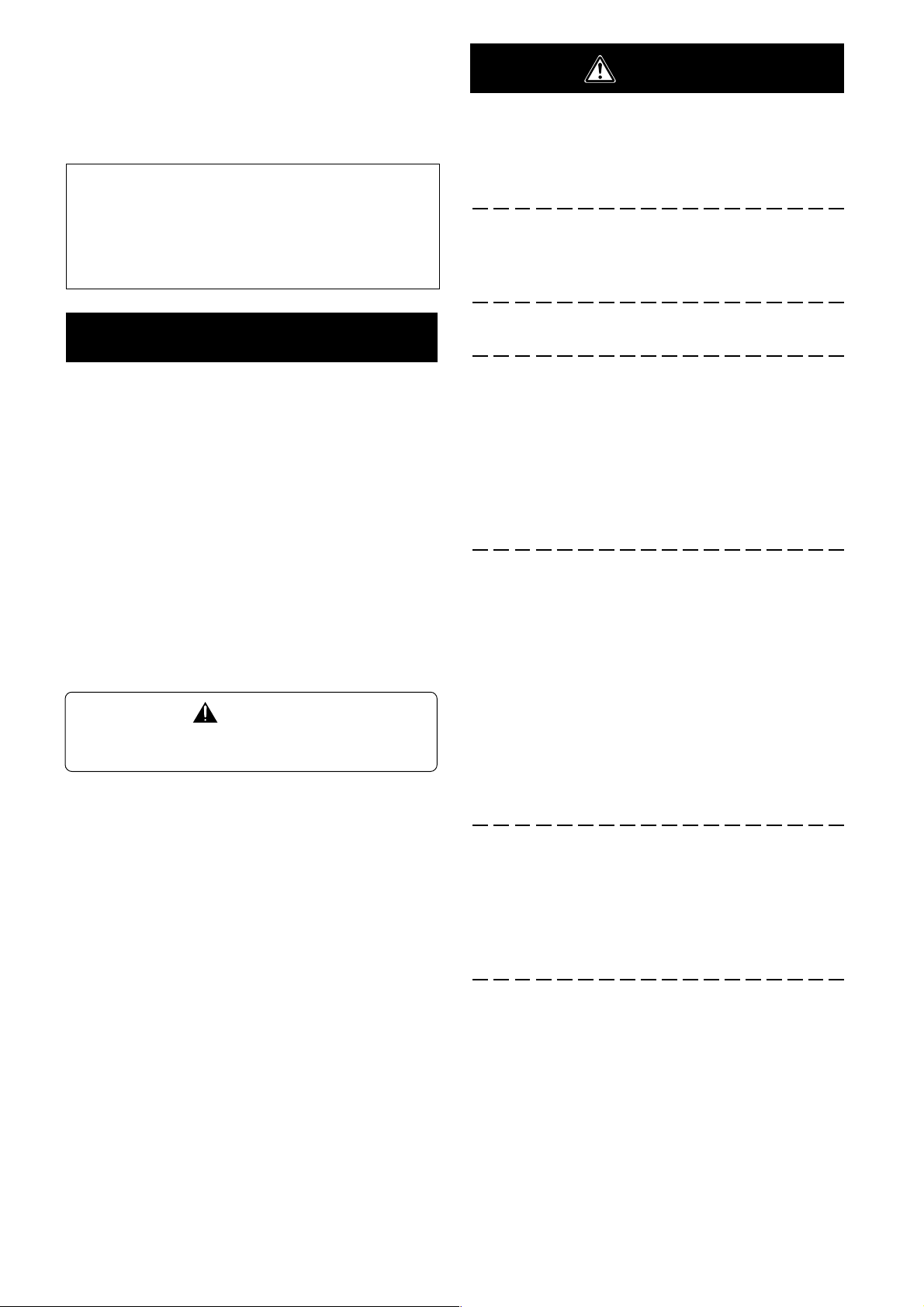
Check to make sure that you have all the enclosed parts
before assembly and installation.
Table top stand x 1
Support columns x 2
Installation screws 1 (M8 x 20 mm [13/16 inch]: silver) x 2
[used to anchor the support columns and the table top stand]
Note
Always assemble it on a flat table etc.
Insert the screws in the holes vertically and do not tighten
them with more force than necessary.
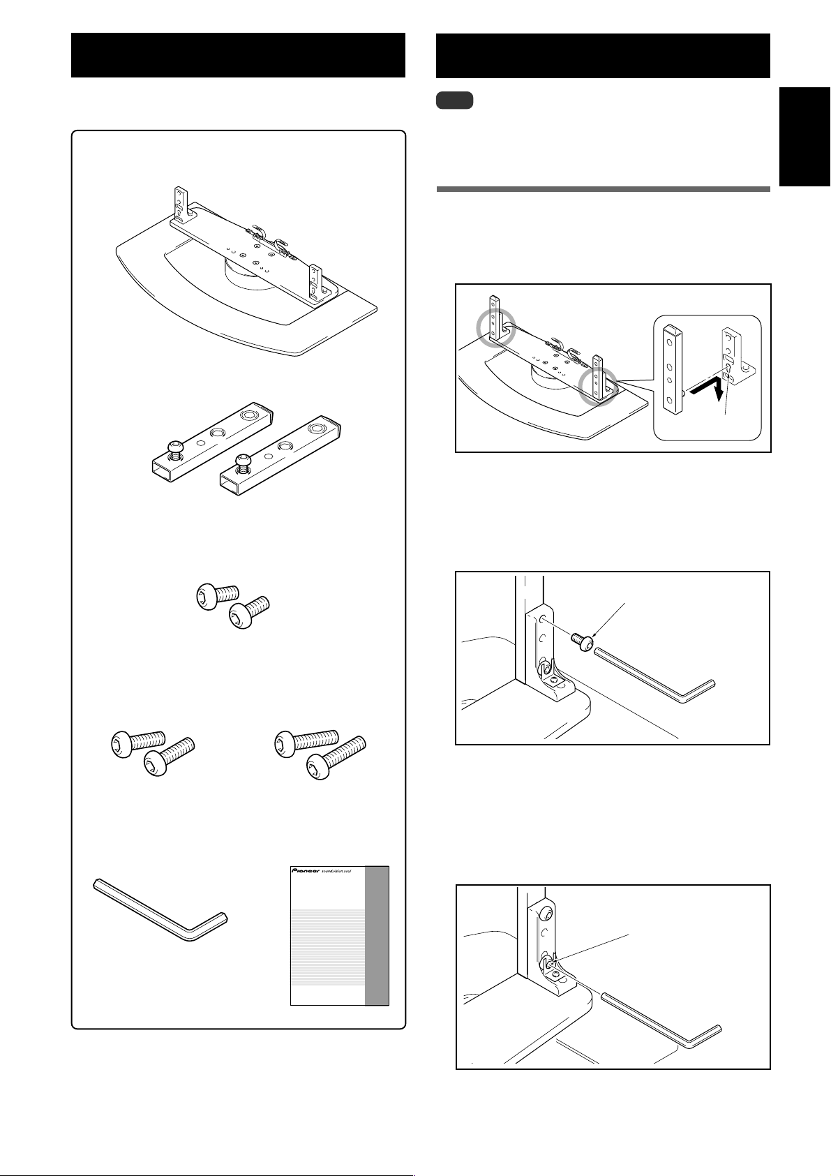
Assembly Procedure
1 Attaching the support columns to the stand.
Insert the head of the screw in the support column into
the hole for the support column in the stand and then
slide it downward.
Front side
Support column
attachment hole
2 Attach the support column to the stand
with the attachment screws 1 on the left
and right of the stand.
Use the enclosed hexagonal wrench to vertically tighten
it in the top hole from the rear.
English
Installation screws 2
(M8 x 30 mm [1-3/16 inch]:
black) x 2
Hexagonal wrench x 1
(Diagonal size: 5 mm [3/16 inch])
Installation screws 3
(M8 x 40 mm [1-9/16 inch]:
black) x 2
Operating instructions
(this document) x 1
Table top stand
Support de couverture de table
PDK-1011
Operating instructions
Mode d’emploi
Attachment screw 1
3 Fully tighten two screws on left and right
of stand which have been loosely screwed
into stand.
Use the provided hexagonal wrench to fully tighten the
attachment screws which have been loosely screwed in
on the left and right sides of the stand.
Tighten the two screws
which have already
been screwed into the
stand.
4 Reconfirm that the attached screw is
firmly tightened.
3
En
Page 4
Attaching the Plasma Display
The weight of a 50 inch plasma display is about 40 kg
(88 lbs), that of a 43 inch model is about 30 kg (66 lbs),
Caution
Note
Be sure to install it on a flat stable location.
Insert the screws in the holes vertically and do not tighten
they have no depth, and are unstable. Therefore, at
least two people must assemble and install them.
them with more force than necessary.
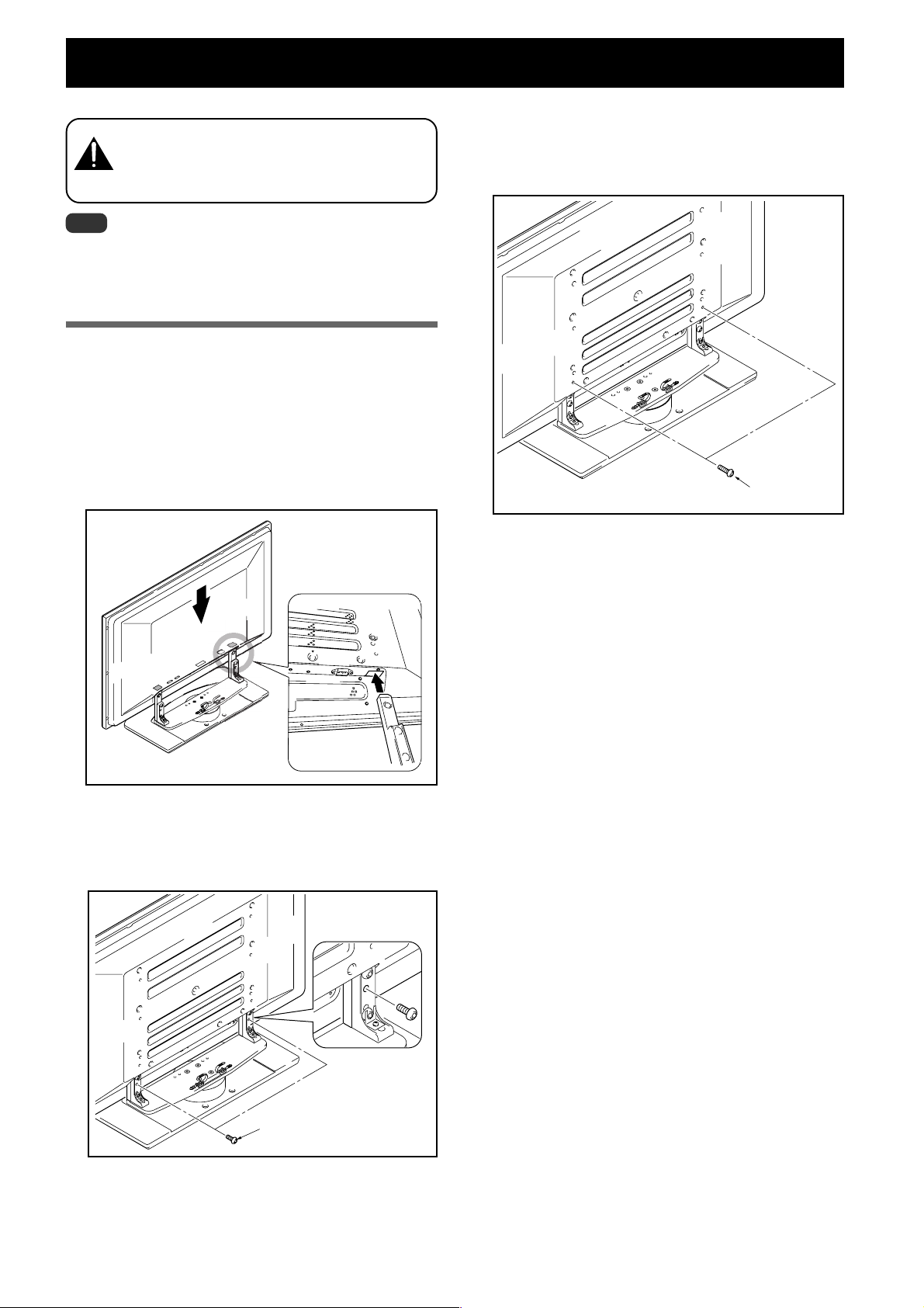
Attachment Method
1 Attaching the plasma display to the stand.
Fit the stand’s support columns into the slots in the center of
the bottom of the plasma display then slowly insert them
directly into the slots. Be extremely careful not to insert the
support columns of the stand into any part of the plasma
display other than the stand insertion slots. Note that doing
so might damage the plasma display panel or its ports or
result in the warping of the stand.
Line up the column
supports with the bottom
of the plasma display as
indicated in the accompanying diagram.
3 Securing the plasma display with attach-
ment screws 3.
Secure them using the enclosed hexagonal wrench.
Attachment
screw 3
4 Attaching the speakers.
Refer to the operating instructions for the speaker for
the installation method.
2 Securing the plasma display with attach-
ment screws 2.
Secure them using the enclosed hexagonal wrench.
Attachment screw 2
4
En
Page 5
Installing the Product on a Rack etc.
Be sure to observe the following precautions when moving
or installing this product with a plasma display into a rack or
other enclosure.
Precautions when moving
When moving the product more than a few meters,
first remove the speaker, then remove the plasma
Caution
display from the stand and move the speaker, plasma
display, and stand separately.
Precautions when installing in a rack
or other enclosure
When installing in a rack or other enclosure, hold the
plasma display by the handles located on the rear
Caution
and bottom of the plasma display. If you hold the
speakers, they may be damaged or twisted.
Hold the
plasma display
by its handles
and from the
bottom.
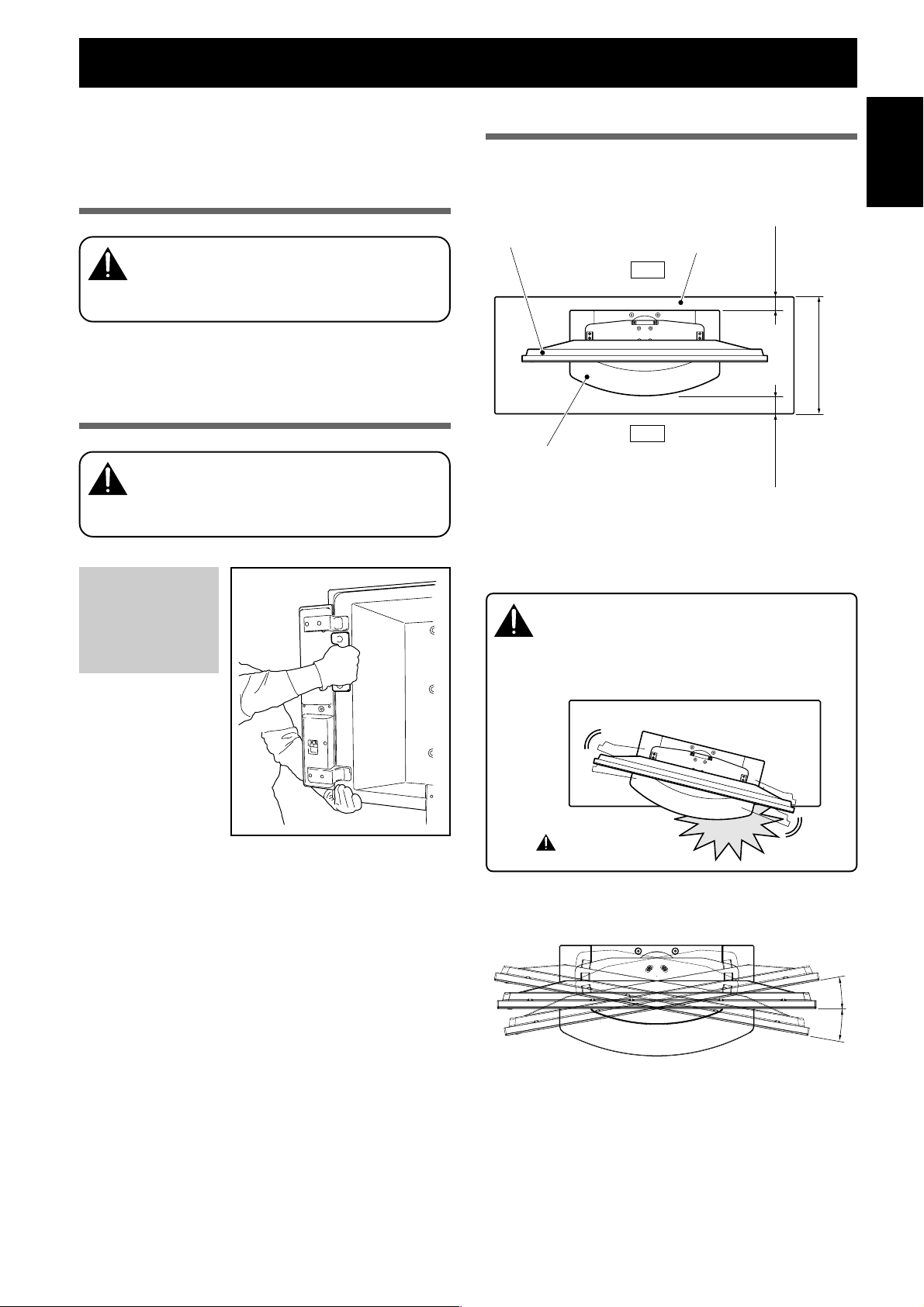
Installation precautions
Make sure that you always secure a space at least as large
as that shown in the following diagram in front of and
behind the table top stand.
Plasma display
Back
Front
Table top stand
But when using a rack for which the aforementioned
spaces cannot be secured, place the rack as close to a wall
as possible and give priority to securing the space in front.
If the stand protrudes from the rack, it could cause
unforeseen accidents such as the equipment break-
Caution
ing or falling over.
When rotating, take care not to allow the display
to bump into walls or surrounding objects.
Rack
Min. 10 mm
(13/32 inch)
Min. 30 mm
(1-3/16 inch)
Depth of the rack
430 mm (16-15/16 inch)
English
or more recommended
Protrusion is dangerous.
Angle of rotation
10˚
10˚
5
En
Page 6

Preparing the Cables
Use the enclosed cable binders to bind the cables.
Note
Be very careful not to apply force to the bases of the cables.
Using the cable binders
1 Gathering cables and placing them on the
cable binder.
2 Passing the cable binder through the hole
on its end.
3 Pulling the end of the cable binder to
secure the cables.
Removing a cable binder
If the secured part is removed
from the cable binder hole, it is
unlocked.
Secured
part
Hole
En
6
Page 7

Preventing Equipment from Falling Over
After installing the stand, be sure to take measures so that the equipment will not fall over.
Stabilizing on the floor
Stabilize the equipment as shown in the diagram using
screws that are available on the market.
Note
To stabilize the equipment on the
floor use screws that have a
nominal diameter of 6 and that are
at least 20 mm (25/32 inch) long.
Max. 5 mm
(3/16 inch)
Min. 20 mm
(25/32 inch)
Using a wall for stabilization
(43 inch display model in the figure)
1 Attaching falling prevention bolts (hooks)
to the plasma display.
2 Using strong cords or chains to firmly
stabilize it to a wall, pillar, or other sturdy
element.
Perform this work in the same way on the left and
right sides.
The length of the cords or chains used must be long
enough to allow the stand to rotate freely.
Note
Use hooks, ropes, chains, and fittings
that are available on the market.
Recommended hook: Nominal diameter 8
Length 12 to 15 mm (15/32 inch)
12–15mm
(15/32 inch)
English
Positions for inserting screws for stabilizing equip-
ment against the floor: Without speakers
Unit: mm (inch)
* : 43 inch display model
** : 50 inch display model
120
(4-23/32)
575 (22-21/32)*
500 (19-11/16)**
21 (13/16)
Fitting
369 (14-17/32)
2Cord or chain
Detaching the Plasma Display from the Stand
To remove the plasma display from the stand, be sure
to always follow the procedure described below to
Caution
prevent accidents
1 First clear a space on a flat floor etc. where
you can lay the plasma display flat, then
cover the clear space with a sheet or other
material to protect it from scratches or
other damage.
2 Remove the speakers.
3 Referring to steps 2 and 3 in Attaching the
Plasma Display (Page 4.), remove the black
screws (4 screws).
Note
At this time, do not remove the silver screws. If you do,
the column supports might slip out of place and fall over.
4 Holding the plasma display by its handles
and from the bottom, lift the display vertically.
5 Place the screen slowly down onto the
cloth laid out in step 1.
1
Hook
7
En
Page 8

Specifications
External dimensions 684 (W) x 255 (H) x 390 (D) mm (26-15/16 (W) x 10 (H) x 15-11/32 (D) in.)
Weight 14.0 kg (30 lbs 14 oz)
• The above specifications and exterior may be modified without prior notice to improve the product.
Dimensions Diagram
Unit: mm (inch)
When installing speakers flush with the display
1488 (58-19/32) [50 inch display model]
1338 (52-11/16) [43 inch display model]
737 (29-1/32) [50 inch display model]
652 (25-21/32) [43 inch display model]
684 (26-15/16)
When installing speakers set back from the display
1450 (57-3/32) [50 inch display model]
1300 (51-3/16) [43 inch display model]
98 (3-27/32)
28 (1-3/32)
80
(3-5/32)
816.5 (32-5/32) [50 inch display model]
145.5
731.5 (28-13/16) [43 inch display model]
(5-23/32)
390 (15-11/32)
98 (3-27/32)
28 (1-3/32)
167 (6-9/16)
Without speakers
8
En
737 (29-1/32) [50 inch display model]
652 (25-21/32) [43 inch display model]
1270 (50) [50 inch display model]
1120 (44-3/32) [43 inch display model]
737 (29-1/32) [50 inch display model]
652 (25-21/32) [43 inch display model]
684 (26-15/16)
684 (26-15/16)
80
(3-5/32)
145.5
816.5 (32-5/32) [50 inch display model]
731.5 (28-13/16) [43 inch display model]
(5-23/32)
390 (15-11/32)
80
(3-5/32)
816.5 (32-5/32) [50 inch display model]
145.5
731.5 (28-13/16) [43 inch display model]
(5-23/32)
390 (15-11/32)
167 (6-9/16)
98 (3-27/32)
28 (1-3/32)
167 (6-9/16)
Published by Pioneer Corporation.
Copyright © 2003 Pioneer Corporation.
All rights reserved.
Page 9

Nous vous remercions d’avoir procéder à l’achat d’un produit
Pioneer.
Veuillez lire attentivement ce Mode d’emploi pour savoir comment
opérer correctement et en toute sécurité votre modèle.
Nous vous conseillons de conserver soigneusement de Mode
d’emploi dans un endroit sûr et à proximité afin de pouvoir vous y
référer le cas échéant.
Installation
¶ Veuillez consulter votre revendeur si vous rencontrez des
difficultés lors de l’installation.
Pioneer n’assumera aucune responsabilité pour tout
dommage résultant d’une installation incorrecte, d’une
utilisation incorrecte, une modification de ce produit ou
encore de désastres naturels.
Table des matières
Attention ............................................................................ 9
Vérification des pièces contenues dans le carton
d’emballage ..................................................................... 10
Assemblage du support ................................................. 10
Installation et fixation de l’écran
d’affichage plasma .......................................................... 11
Installation du produit sur une étagère, etc. ................ 12
Préparation des câbles ................................................... 13
Prévenir le basculement et la chute de l’équipement ... 14
Démontage de l’écran plasma du support ................... 14
Spécificités....................................................................... 15
Diagramme indiquant les dimensions .......................... 15
ATTENTION
Ce symbole indique un danger ou une pratique dangereuse
risquant de compromettre la sécurité qui peut provoquer des
blessures ou des dégâts matériels.
Attention
Ce produit est un support de couverture de table conçu
exclusivement pour les écrans d’affichage plasma fabriqué par
Pioneer : PRO-1110HD / PRO-910HD. Veuillez noter que ce produit
n’a pas été conçu pour être utilisé avec d’autres équipements.
Pour de plus amples informations, veuillez contacter le vendeur où
vous avez acheté votre écran d’affichage.
Veuillez ne pas installer le produit d’une manière autre que celle
spécifiée ou modifier ce dernier. En outre, veuillez ne pas utiliser
ce support pour un écran d’affichage plasma autre que ceux pour
lesquels il a été conçu et ni le modifier ou l’utiliser à des fins
autres que celles pour lesquelles il a été conçu.
Une installation incorrecte est extrêmement dangereuse car celleci peut provoquer le basculement du support ou un autre accident.
Emplacement d’installation
• Sélectionner un emplacement qui est assez solide pour
supporter le poids du support et de l’écran d’affichage.
• S’assurer que l’emplacement d’installation est bien plane et à
niveau et prendre toutes les précautions utiles et
indispensables lors de l’installation du support afin de veiller à
ce que le poids soit bien uniformément réparti.
• Ne pas installer le support à l’extérieur, à proximité d’une
source thermale ou sur la plage.
• Ne pas installer le support à un endroit où il pourrait être soumis
à des chocs ou à des vibrations.
Assemblage et installation
• Assembler le support conformément aux instructions
concernant l’assemblage et fixer solidement toutes les vis
aux endroits prévus à cet effet.
On a constaté des cas où des accidents imprévus sont
survenus (endommagement de l’équipement, chute, etc.)
après l’installation de l’écran d’affichage parque le support
n’avait pas été installé comme indiqué dans les instructions.
• L’écran d’affichage doit toujours être installé au moins par
deux personnes afin de veiller à ce qu’il soit installé en
toute sécurité.
• Avant de procéder à l’installation, mettre l’écran ainsi que
les équipements périphériques hors tension en coupant
l’alimentation, puis retirer la prise du câble d’alimentation
électrique de la prise femelle murale.
English
Français
Cet article peut effectuer une rotation de 10° vers la gauche ou
vers la droite. Veuillez ne pas placer d’objets à l’intérieur de la
plage de rotation de cet article de telle sorte que durant une
utilisation habituelle ou lorsqu’on le fait tourner, il ne dépasse pas
de l’étagère ou de l’emplacement sur lequel il a été installé. Si on
n’observe pas cette précaution, il existe un risque d’accidents
imprévus comme un endommagement de l’équipement ou une
chute (Voir page 12).
Il convient de prévenir les accidents causés par la chute du produit
en prenant des mesures fiables pour éviter le basculement et la
chute (Voir page 14).
9
Fr
Page 10

Vérification des pièces contenues
Assemblage du support
dans le carton d’emballage
Procéder à cette vérification afin de vous assurez que vous
possédez bien toutes les pièces en questions avant de procéder à
l’assemblage et à l’installation du support.
Support de couverture de table x 1 unité
Colonnes de support x 2 unités
Vis d’installation 1 (M8 x 20 mm : argenté) x 2 unités
[Utilisées pour fixer les colonnes de support et le support de
couverture de table]
Remarques
Toujours assembler le support sur une table bien plane, etc.
Introduire les vis à la verticale et ne pas serrer les vis plus qu’il
est nécessaire.
Procédure d’assemblage
1 Fixation des colonnes de support au support.
Insérer la tête de la vis dans la colonne de support à l’intérieur
de l’orifice réservé à la colonne de support dans le support et
faire coulisser ensuite vers le bas.
Orifice de fixation
de la colonne de
Face avant
support
2 Fixer la colonne de support au support avec les
vis d’installation 1 sur le côté gauche et sur le
côté droit du support.
Veuillez utiliser la clé hexagonale jointe pour visser à la
verticale les vis dans l’orifice supérieur à partir de l’arrière.
Vis d’installation 1
Vis d’installation 2
(M8 x 30 mm : noir) x 2 unités
Clé hexagonale (à six pans)
x 1 unité
(Taille en diagonale : 5 mm)
Vis d’installation 3
(M8 x 40 mm : noir) x 2 unités
Mode d’emploi (ce document)
x 1 exemplaire
Table top stand
Support de couverture de table
PDK-1011
Operating instructions
Mode d’emploi
3 Bien serrer à fond les vis d’installation sur le
côté gauche et sur le côté droit du support qui
avaient été légèrement vissés dans le support.
Veuillez utiliser la clé hexagonale jointe pour bien visser à fond
les vis d’installation sur le côté gauche et sur le côté droit du
support qui avaient été légèrement vissés dans le support.
Resserrer les deux vis qui
avaient été déjà vissées
dans le support.
10
4 Revérifier que les vis d’installation sont bien
vissées à fond.
Fr
Page 11

Installation et fixation de l’écran d’affichage plasma
Le poids d’un écran plasma de 50 pouces est d’environ
40 kg, et celui d’un modèle de 43 pouces d’environ 30 kg.
Attention
Remarques
Toujours assembler l’écran plasma sur une surface table bien
Introduire les vis à la verticale et ne pas serrer les vis plus qu’il
Ils n’ont pas de profondeur et sont instables.
plane et stable.
est nécessaire.
Méthode de fixation
1 Installation de l’écran plasma sur le support.
Placer les colonnes de support du support dans les fentes au
centre de la partie inférieure puis les insérer lentement et
directement dans les fentes. Veillez très soigneusement à ne
pas insérer les colonnes de support du support dans une
quelconque partie de l’écran d’affichage plasma autres que les
fentes prévues à cet effet. Veuillez noter que si vous faites
cela vous risquez d’endommager l’écran d’affichage ou les
entrées ou encore le support.
Aligner les supports de
colonne avec la partie
inférieure de l’écran d’affichage
d’écran comme indiqué sur le
diagramme ci-joint.
3 Fixer solidement l’écran d’affichage plasma
avec les vis d’installation 3.
Bien visser celles-ci au moyen de la clé hexagonale jointe avec
le support.
Français
Vis d’installation 3
4 Mise en place des haut-parleurs.
Veuillez vous référer au mode d’emploi concernant les hautparleurs pour la méthode d’installation.
2 Fixer solidement l’écran d’affichage plasma
avec les vis d’installation 2.
Bien visser celles-ci au moyen de la clé hexagonale jointe avec
le support.
Vis d’installation 2
11
Fr
Page 12

Installation du produit sur une étagère, etc.
Veuillez respecter strictement les précautions suivantes lorsque
vous déplacez ou installez le produit avec un écran d’affichage
plasma sur une étagère ou un autre espace limité.
Précautions à respecter lors du
déplacement du produit
Lorsque l’on procède au déplacement de l’appareil sur
une distance supérieure à plusieurs mètres, veuillez
Attention
démonter tout d’abord les haut-parleurs. Puis démonter
également l’écran d’affichage plasma de son support et
transporter chaque partie séparément.
Précautions avant d’installer sur une étage
ou à un autre emplacement exigu
Lors de l’installation sur une étagère ou un endroit exigu,
tenir l’écran d’affichage plasma par les poignée situées à
Attention
l’arrière et à la partie inférieure de l’écran. Si vous tenez
les haut-parleurs, ils risquent d’être endommagés ou
tordus.
Précautions d’installation
Veillez à toujours garantir un espace au moins aussi large que celui
indiqué sur le diagramme suivant à l’avant et à l’arrière du support
de couverture de table.
Ecran plasma
Arrière
Avant
Support
Lorsque vous utilisez une étagère, etc.. pour laquelle l’espace
susmentionné ne peut être garanti, veuillez placer l’étagère aussi
près que possible du mur et donner la priorité à l’espace situé en
avant.
Etagère
10 mm mini
Profondeur de l’étagère
Nous recommandons 430 mm
30 mm mini
au minimum.
Veuillez tenir l’écran
plasma par ces
poignées et par le
dessous.
Si le support dépasse en avant de l’étagère, ceci risque
de provoquer des accidents imprévus comme
Attention
l’endommagement de l’équipement ou une chute.
Lors d’une rotation du support, veuillez faire attention
de ne pas faire entrer en contact l’écran avec le mur ou
avec les autres objets environnants.
Le dépassement est
dangereux.
Angle de rotation
10˚
10˚
12
Fr
Page 13

Préparation des câbles
Utiliser les serre-câbles pour regrouper les câbles.
Remarque
Veillez à ne pas mettre trop de force à la base de câbles.
Utilisation des serre-câbles
1 Rassembler les câbles et les placer sur le serre-
câble.
Français
2 Faire passer le serre-câble à travers le trou
situé à son extrémité.
3 Tirer sur l’extrémité du serre-câble pour bloquer
les câbles.
Retirer un serre-câble
Si la partie bloquée est enlevée
de l’orifice du serre-câble, celuici est débloqué.
Partie bloquée
Orifice
13
Fr
Page 14

Prévenir le basculement et la chute de l’équipement
Après avoir installé le support, veillez à prendre des mesures pour que l’équipement ne tombe pas.
Stabilisation sur la base
Veuillez stabiliser l’équipement comme indiqué sur le diagramme
en utilisant des vis vendues dans le commerce.
Remarque
Afin de stabiliser l’équipement sur
le sol, veuillez utiliser les vis ayant
un diamètre nominal de 6 mm et
une longueur d’au moins 20 mm.
5 mm maxi
20 mm mini
Utilisation d’un mur pour la stabilisation
du support.
(Modèle d’écran de 43 pouces comme indiqué sur la
figure)
1 Fixation des boulons empêchant la chute
(crochets) à l’écran plasma.
2 Utiliser des câbles solides ou des chaînes pour
stabiliser solidement le dispositif à un mur, un
pilier ou autres éléments stables.
Veuillez effectuer ces travaux de la même manière à
gauche et à droite.
La longueur des câbles ou des chaînes utilisés doit être
suffisante pour permettre au support de tourner sur sa
base librement.
Remarque
Utiliser des crochets, des chaînes et d’autres
dispositifs de fixation qui sont en vente dans
le commerce.
Crochet recommandé : Diamètre nominal 8,
longueur : de 12 à 15 mm.
12–15mm
Position d’installation des vis de fixation au sol : sans les
haut-parleurs
Unité : mm
575 (Ecran d'affichage 50 pouces)
500 (Ecran d'affichage 43 pouces)
120
21
2Câble ou chaîne
369
Attache
Démontage de l’écran plasma du support
3 En vous référant aux opérations 2 et 3 décrites
Attention
Lorsque l’on démonte l’écran d’affichage plasma de son
support, veuillez respecter strictement la procédure
indiquée ci-dessous afin de prévenir les accidents.
1 Veuillez coucher au préalable l’écran
d’affichage plasma sur une surface plane
comme une plancher, etc. et garantir un espace
suffisant. Afin d’éviter d’égratigner l’écran ou
4 Tout en tenant l’écran hexagonal par ses
de l’endommager, placer une pièce de tissu
(drap, etc.) sur cette surface pour protéger
l’écran.
5 Veuillez placer en douceur l’écran sur la surface
2 Retirer les haut-parleurs.
Crochet
1
dans ‘’ Installation et fixation de l’écran
d’affichage plasma ‘’ (p. 11), veuillez retirer les
4 vis noires.
Remarque
A ce moment-là, n’enlevez pas la vis argentée car cela risquerait
de désolidariser les colonnes de support et de faire basculer
l’appareil.
poignées et par le fond, veuillez relever à la
verticale celui-ci.
en tissu préparé à l’étape 1.
14
Fr
Page 15

Spécificités
Dimensions extérieures : 684 (largeur) x 255 (hauteur) x 390 (profondeur) mm
Poids : 14,0 kg
• Les caractéristiques techniques indiquées ci-dessus et les dimensions extérieures peuvent êtres modifiées sans préavis en vue
d’améliorer le produit.
Diagramme indiquant les dimensions
Unité : mm
Haut-parleurs installés dans l’alignement de l’écran
1488 (Ecran d'affichage 50 pouces)
1338 (Ecran d'affichage 43 pouces)
737 (Ecran d'affichage 50 pouces)
652 (Ecran d'affichage 43 pouces)
684
Haut-parleurs installés en retrait de l’écran
1450 (Ecran d'affichage 50 pouces)
1300 (Ecran d'affichage 43 pouces)
98
80
816,5 (Ecran d'affichage 50 pouces)
731,5 (Ecran d'affichage 43 pouces)
145.5
390
98
28
Français
28
167
737 (Ecran d'affichage 50 pouces)
652 (Ecran d'affichage 43 pouces)
Sans les haut-parleurs
737 (Ecran d'affichage 50 pouces)
652 (Ecran d'affichage 43 pouces)
684
1270 (Ecran d'affichage 50 pouces)
1120 (Ecran d'affichage 43 pouces)
684
80
145,5
816,5 (Ecran d'affichage 50 pouces)
731,5 (Ecran d'affichage 43 pouces)
390
98
28
80
816,5 (Ecran d'affichage 50 pouces)
731,5 (Ecran d'affichage 43 pouces)
145,5
390
Publication de Pioneer Corporation.
© 2003 Pioneer Corporation.
Tous droits de reproduction et de traduction réservés.
167
167
15
Fr
Page 16

Published by Pioneer Corporation.
Copyright © 2003 Pioneer Corporation.
All rights reserved.
PIONEER CORPORATION 4-1, Meguro 1-Chome, Meguro-ku, Tokyo 153-8654, Japan
PIONEER ELECTRONICS (USA) INC. P.O.BOX 1540, Long Beach, California 90801-1540, U.S.A., TEL: 1-310-952-2111
PIONEER EUROPE NV MULTIMEDIA DIVISION
PIONEER ELECTRONICS AUSTRALIA PTY.LTD. 178-184 Boundary Road, Braeside, Victoria 3195, Australia, TEL: 61-39-586-6300
PIONEER ELECTRONICS ASIACENTRE PTE. LTD. 253 Alexandra Road #04-01, Singapore 159936, TEL: 65-6472-1111
PIONEER HIGH FIDELITY TAIWAN CO., LTD.
PIONEER ELECTRONICS (CHINA) LTD. Room 1704-06, 17/F World Trade Centre, 280 Gloucester Rd. Causeway Bay, Hong Kong, TEL: 852-2848-6488
PIONEER GULF FZE Lob 11-017, Jebel Ali Free Zone P.O. BOX 61226, Jebel Ali, Dubai, United Arab Emirates, TEL: 971- 4-8815756
PIONEER ELECTRONICS DE MEXICO S.A. DE C.V. Blvd. Manuel Avila Camacho 138 10 piso Col.Lomas de Chapultepec, Mexico, D.F. 11000 TEL: 55-9178-4270
Pioneer House Hollybush Hill, Stoke Poges, Slough SL2 4QP, U.K., TEL: 44-1753-789-789
13FL., No44 Chung Shan North Road, Sec.2. Taipei, Taiwan, TEL: 886-2-2521-3588
Printed in Japan / Imprimé au Japon <AZR1082-A>
 Loading...