

Page 1

Optical System Cable (PDA-H05)
Installation Manual (Ver. 1.0)
This manual provides precautions and information for installation, preparation, and handling of the optical
system cable.
Before installation and preparatory work, choose a safe and appropriate site after thorough consideration
of construction, materials used, strength, and surroundings. If adequate safeguards are not in place,
immediately halt the installation process and discontinue marketing activities.
PRECAUTIONS:
• We accept no responsibility for losses resulting from the use of parts other than those supplied by us.
• We guarantee the performance of our products only when they are assembled and adjusted in
accordance with this installation manual.
• The specifications and external designs shown in this installation manual are subject to change
without notice.
CAUTION
Exclamation marks placed within triangles are intended to alert users to the presence of important
safety information. Be sure to read instructions indicated by this symbol.
Page 2
1. Product SummaryContents
1. Product Summary ..................................................... 2
2. Cautions During Use ................................................. 2
3. Specifications ............................................................ 4
4. Components .............................................................. 5
5. Drawings of External Appearance ........................... 6
6. Names of Parts .......................................................... 7
7. Installation Site Requirements ................................ 8
7-1 Temperature and humidity conditions ................ 8
7-2 Prevent condensation ........................................ 8
7-3 Repeater box anchoring method ........................ 8
7-4 Other installation conditions ............................... 8
8. When Passing the Cables Thorough the CD Tube ... 9
8-1 The CD (Combined Duct) tube ........................... 9
8-2 Precautions when installing a CD tube .............. 9
8-3 Passing cables through the CD tube .................. 9
8-4 Method of combining cables before the pass-
through step ..................................................... 10
9. Optical System Cable Connection Procedure....... 11
9-1 Connecting the Media Receiver ....................... 11
9-2 Connecting the Plasma Display ........................ 12
9-3 Connection of Optical cable ............................. 14
9-4 Connection of AC/DC power adapter ............... 15
10. Troubleshooting ....................................................... 16
11. After-sales Service ................................................... 21
This product enables Display and Media Receiver to be
connected up to 30 meters longer apart.
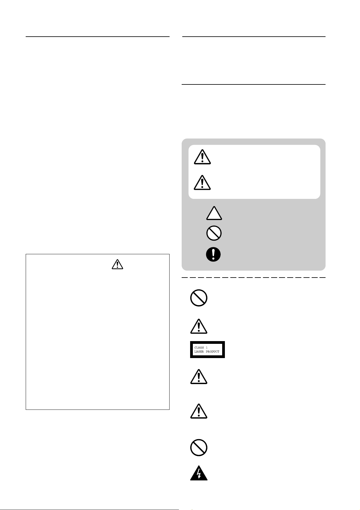
2. Cautions During Use
Note: to draw the attention of the user to potentially
hazardous situations, various warnings and cautions,
accompanied by corresponding symbols, are indicated in
the documentation and on the product. The meanings of
these symbols are as follows:
This symbol indicates the presence
WARNING
CAUTION
of a potential danger that could
result in serious, even fatal, injury.
This symbol indicates the presence
of a potential danger that could
result in electric shock or damage to
equipment.
WARNING - CAUTION
(Be careful during operation)
STOP!
(This action is prohibited.)
CAUTION
• To prevent injury and material damage, thoroughly read this
manual and all labels found on the equipment before
attempting to mount, install, move, or adjust the product.
• Do not install the unit outside or in the open air. Doing so
will lead to water seepage into the system, resulting in fire
or electric shock.
• Be especially careful when working around parts of the
system that have sharp edges.
• When performing installation work from a height, take
suitable precautions to guard against falling. Set up a barrier
around the work site to prevent accidentally dropped objects
from injuring persons standing or walking below.
• Keep all foreign objects out of the unit. Do not tamper with
the unit, or fire or electric shock may result.
• Observe the following operating environmental limitations:
Temperature: 0 to 40°C (32 to 104°F)
Humidity: Up to 85%
• Install the unit only in properly ventilated areas.
STOP
CAUTION
CAUTION
WARNING
STOP
TAKE HEED!
(Do not neglect to carry out
this action.)
Do not carry out this action in the case of
Plasma Hivision TVs, carry out modifications
or carry out such actions in the case of similar
products.
Do not look directly into devices which emit
laser light.
AEL Class 1 laser product per FDA/CDRH
and IEC 60825-1
Use of controls or adjustments or performance
of procedures other than those specified
herein may result in hazardous radiation
exposure.
Handling the cord on this product or cords
associated with accessories sold with the
product will expose you to chemicals listed on
proposition 65 known to the State of California
and other governmental entities to cause cancer
and birth defect or other reproductive harm.
Wash hands after handling.
Do not install outdoors, in the vicinity of hot
springs or near the seaside.
Be careful of uninsulated “high voltage”
components within the product enclosure;
these may be of sufficient magnitude to
constitute a risk of electric shock to the
2
operator.
Page 3
IMPORTANT NOTICE
The serial number for this equipment is located on the
bottom of the repeater boxes. Please write this serial
number on the enclosed warranty card and keep in a
safe place for your own security.
TO PREVENT THE RISK OF ELECTRIC SHOCK, DO NOT
REMOVE COVER. NO USER-SERVICEABLE PARTS INSIDE.
REFER SERVICING TO QUALIFIED SERVICE PERSONNEL.
WARNING
This apparatus is not waterproof. To prevent
fire or electric shock, do not expose this
apparatus to rain or moisture or bring any
water containers or vessels such as vases,
flower pots, cosmetics containers, medicine
bottles etc., into contact with or near the
apparatus.
WARNING
This product is equipped with a three-wire
grounding (earthing) type plug, that is a plug
having a third (grounding, earthing) pin. The
unit can only be plugged into a grounding
(earthing) type power outlet. This is a safety
feature. If you are unable to insert the plug into
the outlet, contact an electrician to replace the
obsolete outlet. Make sure to capitalise on this
safety feature: do not use an older power outlet
which is not grounded as described.
WARNING
BEFORE PLUGGING IN THE UNIT FOR THE
FIRST TIME, READ THE FOLLOWING
SECTION CAREFULLY.
The voltage of the available power supply
differs according to country or region. Be
sure that the power supply voltage of the
area where this unit will be used meets the
required voltage (e.g., 230V or 120V) written
on the rear panel.
WARNING
No naked flame sources, such as lighted candle,
should be placed on the apparatus. If naked
flame sources accidentally fall down, fire spread
over the apparatus then may cause fire.
STOP
Use the attached AC adapter for this
equipment. Use of any other adapter may
cause a fire.
2. Cautions During Use
This product complies with the Low Voltage Directive (73/23/
EEC, amended by 93/68/EEC), EMC Directives (89/336/EEC,
amended by 92/31/EEC and 93/68/EEC).
This equipment has been tested and found to comply with the
limits for a Class B digital device, pursuant to Part 15 of the
FCC Rules. These limits are designed to provide reasonable
protection against harmful interference in a residential installation. This equipment generates, uses and can radiate radio
frequency energy and, if not installed and used in accordance
with the instructions, may interfere with radio communications. However there is no guarantee that interference will not
occur in a particular installation. If this equipment does cause
harmful interference to radio or
television reception, which can be determined by turning the
equipment off and on, the user is encouraged to try to correct
such interference by one or more of the following measures:
- Reorient or relocate the receiving antenna.
- Increase the distance between the equipment and
receiver.
- Plug the equipment into an outlet on a circuit separate
from the one to which the receiver is connected.
- Consult your dealer or an experienced radio/TV technician
for further help, if necessary.
Information for Users of the equipment
Alterations to or modifications of the equipment carried out
without appropriate authorization may invalidate the user’s
equipment warranty.
This Class B digital apparatus complies with Canadian
ICES-003.
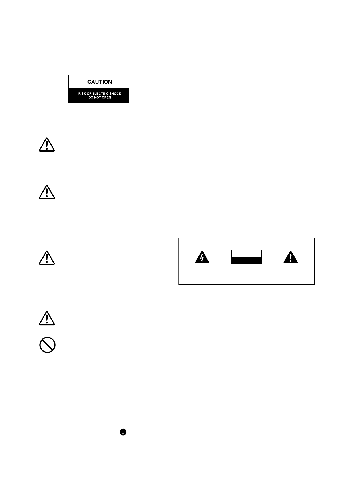
IMPORTANT
CAUTION
RISK OF ELECTRIC SHOCK
DO NO
T OPEN
The “lightning flash” with arrowhead symbol
within an equilateral triangle, is intended to alert
the user to the presence of uninsulated
“dangerous voltage” components within the
product enclosure that may be of sufficient
magnitude to constitute a risk of electric shock
to operators.
CAUTION:
TO AVOID THE RISK OF ELECTRIC SHOCK, DO NOT
REMOVE THE COVER (OR BACK); NO USER
SERVICEABLE PARTS INSIDE. HAVE SERVICING
CARRIED OUT BY QUALIFIED SERVICE PERSONNEL.
The exclamation mark within an equilateral
triangle is intended to alert the user to the
presence of important operating and maintenance
(servicing) instructions in the documentation
which accompanies the appliance.
CAUTION: WHEN POSITIONING THIS EQUIPMENT
ENSURE THAT THE MAINS PLUG AND SOCKET IS EASILY
ACCESSIBLE.
Replacement and mounting of an AC plug on the power supply cord of this unit should be performed only by
qualified service personnel.
IMPORTANT
FOR USE IN THE UNITED
KINGDOM
The wire in this mains lead are
coloured in accordance with the
following code :
Green & Yellow : Earth
Blue : Neutral
Brown : Live
If the plug provided is unsuitable for
your socket outlets, the plug must be
cut off and a suitable plug fitted.
The cut-off plug shoud be disposed of and must
not be inserted into any 13 amp socket as this
can result in electric shock. The plug or adaptor or
the distribution panel shoud be provided with 13
A fuse. As the colours of the wires in the mains
lead of this appliance may not correspond with
coloured markings identifying the terminals in
your plug, proceed as follows;
The wire which is coloured green and yellow must
be connected to the terminal in the plug which is
marked with the letter E or by the earth symbol
, or coloured green or green and yellow
The wire which is coloured blue must be
connected to the terminal which is marked with
the letter N or coloured black.
The wirre which is coloured brown must be
connected to the terminal which is marked
with the letter L or coloured red.
NOTE
After replacing or changing a fuse, the fuse
cover in the plug must be replaced with a
fuse cover which corresponds to the colour
of the insert in the base of the plug or the
word that is embossed on the base of the
plug, and the appliance must not be used
without a fuse cover. It lost replacement fuse
covers can be obtained from your dealer.
Only 13 A fuse approved by B.S.I or A.S.T.A
to BS1362 shoud be used.
3
Page 4

3. Specifications
Mechanical dimensions (W x L x D)
Transmitter and Receiver Boxes: 89.4(W), 97(L), 27.5(D) mm (3-
AC/DC Power adaptor: 60(W), 95(L), 33(D) mm (2-
3
/8(W), 3-3/4(L), 1-5/16(D) in.)
Optical connector: 23(W), 36.7(L), 9.2(D) mm (29/32(W), 1-7/16(L), 3/8(D) in.)
Weight
Transmitter and Receiver Boxes: 490 g (1.08 lbs)
AC/DC Power adaptor: 180 g (0.40 lbs)
Power consumption: Transmitter and Receiver Boxes: 6W
Input Power (Rated Voltage and Frequency): 100-240 V AC, 50/60 Hz
Length of Cables / Weight
System cable (Connector: white): 0.75 m (2.46 ft) / (with Repeater Box)
System cable (Connector: black/silver): 0.75 m / 100 g (2.46 ft / 0.22 lbs)
Optical cable: 30 m / 550 g (98.43 ft / 1.21 lbs)
Package dimensions (W x L x D): 415(W), 315(L), 130(D) mm (16-
17
11
/32 (W), 12-13/32(L), 5-1/8(D) in.)
/32(W), 3-13/16(L), 1-3/32(D) in.)
Package weight: 4.0 kg (8.8 lbs)
Operating environment temperature range: 0 to 40°C (32 to 104°F) (governed by installation conditions)
Operating environment humidity range: Up to 85% (condensation shall not occur)
4
Page 5
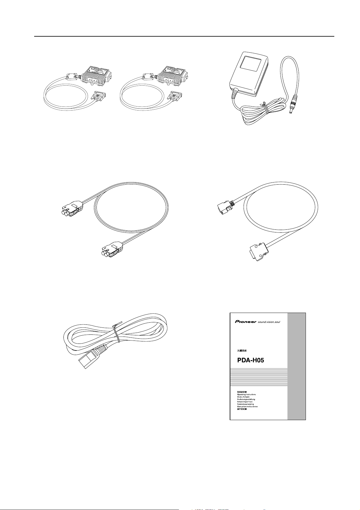
4. Components
Repeater Boxes (Transmitter: x1, Receiver: x1) AC/DC Power adapter: x2
Optical cable: x1
Note: Do not bend to a radius of
curvature less than 15mm.
AC power cord: x2
Guarantee Certificate: x1
System cable (Connector: Black/Silver) : x2
光システムケーブル
Optical System Cable
Optique Système Câble
System-Lichtleiterkabel
Cavo Fibra Ottica
Optische Systeem Kabel
Cable de Sistema Óptico
Operating instructions : x1
5
Page 6
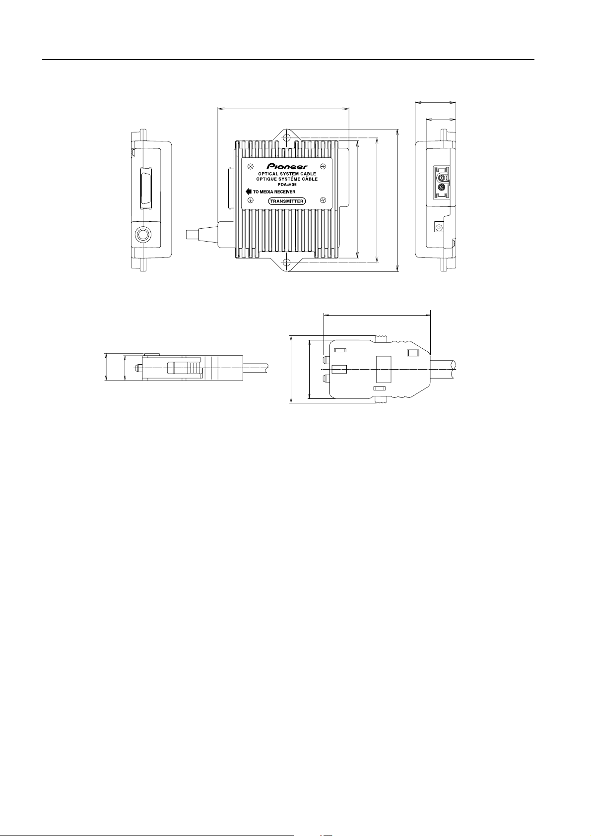
5. Drawings of External Appearance
Mechanical dimension of repeater boxes
Unit: mm (inch)
(3-
89.4
17
/32)
80
27.5
3
/32)
(1-
20
25
(
/32)
)
)
32
/
5
85
(3-
)
32
16
/
/
11
13
97
(3-
(3-
Outer size of optical connector
Unit: mm (inch)
)
)
32
8
/
/
3
8.4
9.2
(
11
(
23
36.7
7
/16)
(1-
)
)
32
32
/
/
20
29
25
(
(
6
Page 7
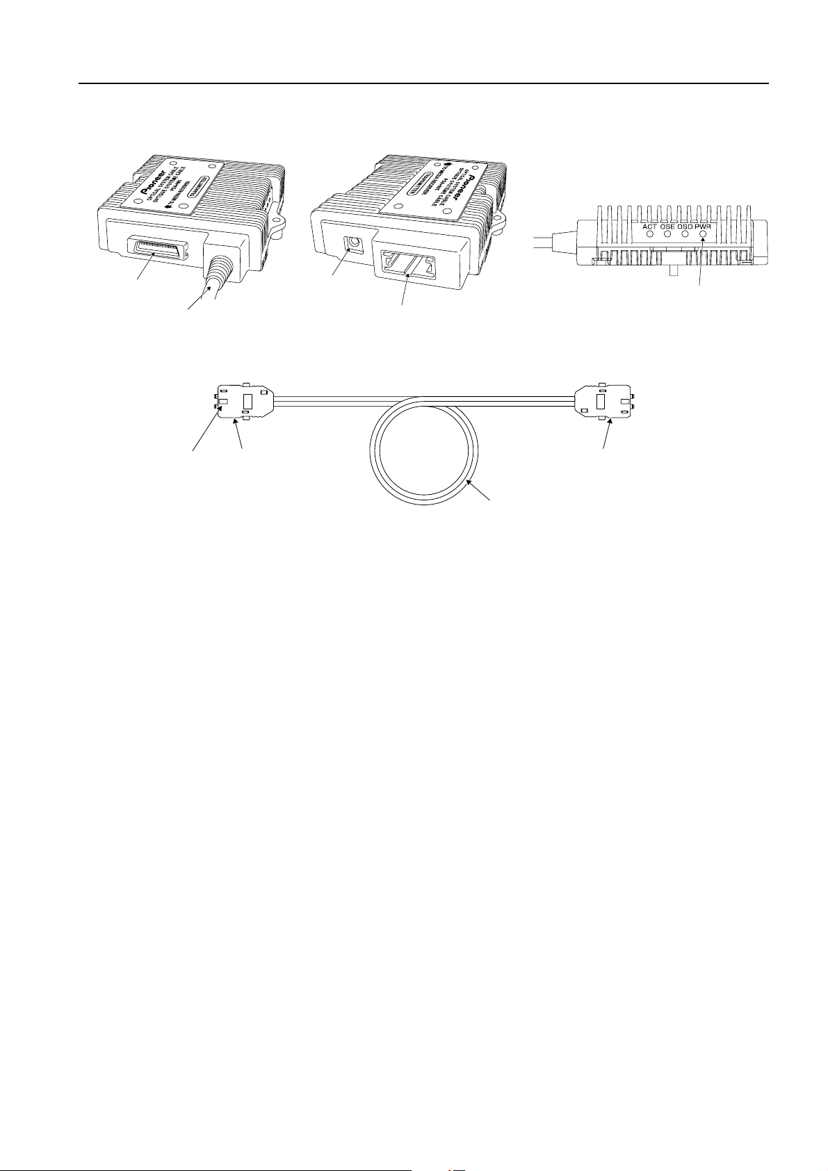
6. Names of Parts
Optical connector Optical connector
Optical cable
Foolproof protrusion
System connector
(Silver)
System cable (Connector: White)
Optical receptacle
Power receptacle
Power indicator
Nomenclature of an indicator and receptacles in repeater box
7
Page 8

7. Installation Site Requirements
7-1 Temperature and humidity conditions
The installation site should meet the following conditions:
• Operating temperatures: 0 to 40°C (32 to 104°F) (governed by installation conditions)
• Operating humidity: Up to 85%
We recommend against installing electronic products such as this unit in locations subject to high humidity. If the
unit is to be installed in a location subject to relatively high humidity, observe the following:
• Failure to install the unit in unacceptable ways may result in non-warranty damages.
• Make sure the unit is grounded.
• Condensation shall not occur.
• Do not allow water or other liquids to enter the unit.
7-2 Prevent condensation
One of the chief sources of problems during the winter is "condensation". Rapid temperature fluctuations can deposit
water vapor inside the unit, degrading performance. If condensation occurs, turn the unit off and leave it off for an
hour or so. It is also good practice to increase the room temperature gradually.
7-3 Repeater box anchoring method
• To anchor the repeater box by hanging it on a wall for example, use the anchor holes in the tabs on both sides of
the box (see 6. Names of Parts).
• When installing it behind the plasma display, install it below the center line of the plasma display in order to
prevent the exhausted air from raising the temperature.
Lower side
• Because the direction that the repeater box is installed is not specified, install it in a direction suited to the wiring.
– But be certain that it is not enclosed by anything that will block the discharge of heat.
7-4 Other installation conditions
The unit is designed for indoor use, and is not suited for open-air use. Installation in locations that are even partially
exposed to the elements may lead to malfunctions or breakdown caused by any of the following. And if there is
danger of it being exposed to similar effects even when installed indoors, it is necessary to block the outside air by
cooling the casing etc.
• Water and dust
• Changes in temperature and humidity
• Salt-bearing wind
Note:
• The optical cables may break if they are subjected to impact or stress. When fixing a cable, use a method that does
not expose it to impact or stress (i.e., avoid using staplers and other means that involve impact).
• Do not pull or bundle the cables so they apply stress directly on the connectors that are connected. If it is used with
stress applied, the connectors may break or be damaged, or the contact may fail. When winding and bundling excess
cable, make sure that the minimum radius of curvature of optical cable is not less than 15mm (19/32 in.) (diameter
30mm (1-3/16 in.)).
8
Page 9

8. When Passing the Cables Thorough the CD Tube
8-1 The CD (Combined Duct) tube
CD stands for Combined Duct. The CD (Combined Duct) tube is
generally used embedded in concrete or as the protective conduit for
underground cable work, because it is a polyethylene tube that is not
noncombustible.
CD tube dimensions
Tube name Internal diameter External diameter
CD-28 28 mm (1-3/32 in.) 34 mm (1-11/32 in.)
– The nominal diameter that can be used with the optical system cable is CD-28 or more, because of the external
shape of the connector that is used. Be careful not to use one with smaller diameter.
8-2 Precautions when installing a CD tube
Passing nearly 30 m (98.43 ft) of cable through a CD tube is extremely difficult even when it is installed horizontally.
And because it is actually bent and rises or descends vertically, subjecting it to heavy load and making it difficult to
install, please install it to satisfy the following conditions.
1. Make the radius of curvature 500 mm (19-11/16 in.) or more.
(If the ends of the cables are combined as explained in 8-4 when they are passed through, it does not bend lower
than 500 mm (19-11/16 in.).)
2. Make the total rising/descending vertical distance 7 m (22.96 ft) or less, and the vertical height difference 3 m
(9.84 ft) or less.
Examples:
Case A
Case B
3 m
(9.84 ft)
Rising distance
4 m (13.12 ft)
4 m (13.12 ft)
Total rising/descending
distance 7 m (22.96 ft) or less
Descending distance
3 m (9.84 ft)
0 m (0 ft)
AB
Total distance
7 m (22.96 ft)
4 m (13.12 ft) 4 m (13.12 ft)
4 m
(13.12 ft)
Judgement
X
Ceiling
Floor
Vertical height difference
3 m (9.84 ft) or less
Height difference
1 m (3.28 ft)
Judgement
Overall
judgement
X
– If criteria 1 and 2 cannot be satisfied, cut the CD tube midway and pass the cables through them separately.
8-3 Passing cables through the CD tube
When a pull-through line has already been inserted in the CD tube, attach the cables to the pull-through line and pull
them through the CD tube. Make sure the connection has as few protrusions as possible so that it will not break during
the pass through work. If a pull-through line has not been inserted in the CD tube, pull it through with mechanics wire
etc.. Prepare mechanics wire etc. with total length of 30 m (98.43 ft) to pull it through. There are cases where, as the
cable is passed through, it produces high friction with the CD tube so it
cannot be passed through. In such cases apply pass-through grease or
powder to the cables so that they will pass through smoothly.
We recommend that you prepare pass-through grease before passing
the cables through the CD tube.
But it will not move 30 m (98.43 ft) even if grease is used.
In such cases cut the CD tube midway and pass the cables through one
CD tube then through the other CD tube.
Pass-through grease
4 m
(13.12 ft)
9
Page 10

8. When Passing the Cables Thorough the CD Tube
8-4 Method of combining cables before the pass-through step
Step 1
Wrap the connector in a sheet.
Step 2
Overlap the optical cable and the pull-through line.
Optical cable
Sheet that was wrapped
around the repeater box
(cut to the suitable size).
Held in place gently with
cellophane tape.
Knot
(do not let it become undone)
Pull-through line
Step 3
Combine the optical cable and the pull-through
line with adhesive tape being careful that the
knot does not become untied.
The strength is applied in this part when it is
pulled.
Step 4
Anchor the connector with adhesive tape
coated with pass-through grease to protect it
so that it is not exposed and does not catch on
the tube.
Optical cable
Adhesive tape
Slightly separated from
the connector.
Adhesive tape
As short as possible.
(If it is long, resistance is produced when it is passed
through a bent CD tube.)
Notes:
• When pulling the optical cable, do not pull only the connector.
• Be sure to never combine the pull-through line so that it applies direct force on the connector, because this may pull
out the connector.
• The force used to pull the optical cable must be no greater than 40N (Newton).
If it is pulled with force greater than 40N (Newton), the properties of the optical cable will deteriorate.
10
Page 11

9. Optical System Cable Connection Procedure
Important: Please use the installation procedure below. Make sure that the AC power plugs of Plasma Display and Media
Receiver should not be connected to the AC power receptacles.
Note: Be careful not to uncover the dust rubber plugs to the Transmitter and Receiver Boxes and the dust caps for the optical
cables until installing the optical system cable.
Ensure to keep those dust plugs plugged securely whenever disconnecting the system.
9-1 Connecting the Media Receiver
Connection of Transmitter Box and Media Receiver via System Connector (White).
Notes:
• Be careful not to fix cables too tightly when tacking them to walls or to bend them excessively.
• Be careful of the System Cable connector (white). Make sure not to bend or distort the metal connector which would
prevent it from making a proper connection.
Media receiver
Step 9-1
“TRANSMITTER” should be marked here.
Figure 1 – Connection of Transmitter Box and Media Receiver via System Connector (White)
Media Receiver
terminal (white) for
System Cable
connection
System cable
(Connector: White)
11
Page 12

9. Optical System Cable Connection Procedure
9-2 Connecting the Plasma Display
Connect the System Cable (connector: white) of the Receiver to the Display following the same sequence of steps
as in Step 9-1.
Note:
Be careful of the System Cable connector (white). Make sure not to bend or distort the metal connector which would
prevent it from making a proper connection.
Step 9-2
Display terminal
“RECEIVER” should be marked here.
(white) for System
Cable connection
System cable
(Connector: White)
Figure 2 – Connection of Receiver Box and Display via System Connector (White)
And connect one end of the System Cable (connector: silver) to the System Connector (silver) of the Transmitter Box
and the other end to the Receiver Box as shown in Figure 3.
Transmitter box
12
System cable
(connector: silver)
Figure 3 – Connection of System Cable (Connector: Silver)
Page 13

9. Optical System Cable Connection Procedure
Connect the system cable (Connector: black) as shown in Figure 4.
Media receiver
Transmitter box
Display
Receiver box
Media Receiver terminal
(black) for System Cable
connection
System cable
(Connector: Black)
Display terminal (black)
for System Cable
connection
Figure 4 – Connection of the System Cable (Connector: Black)
System cable
(Connector: black)
13
Page 14

9. Optical System Cable Connection Procedure
9-3 Connection of Optical cable
Remove the dustproof cap from Transmitter/Receiver Box. Aligning the foolproof protrusion, push the Optical
Connector home into the Optical Receptacle until it “clicks.”
Cautions
• Do not remove the dustproof cap from the Transmitter or Receiver Box or from Optical Cable until the Optical Cable
has been connected.
Make sure to keep the dust plugs securely in place whenever disconnecting the system.
• Be careful not to touch the optical connector with your fingers or drop the connector.
• When removing the Optical Connector from the Transmitter/Receiver Box, do not pull the Cable but, rather, pull the
Connector straight out while squeezing the clips on either side of the connector.
1 Do not remove the dustproof cap from the
Optical Cable/Repeater Box until immediately
before connecting the cable.
Repeater box Optical cable
Do not remove the dustproof cap until immediately
before connection.
Step 9-3
Step 9-3
2 When connecting the Optical Cable to the Repeater
Box, always push the connector home while
squeezing the clips on either side of the connector.
When connecting, be sure to
hold the connector, squeezing
the clips (marked with an arrow).
Optical receptacle
Optical cable
Align the connector with
the slot in the receptacle.
The foolproof protrusion
goes to the bottom.
Figure 5 – Connection of Optical Cable to Repeater Box
If subjected to physical shock or force, the optical cable may bend or
break, thus preventing it from transmitting signals. When anchoring
it, do not use any tools that would exert undue force such as
staplers; always fix the cable gently but firmly, for example with a
cable clamp, as illustrated on the right.
Place a dustproof cap on any unconnected Optical Connector.
Any foreign particles adhering to or within either Optical Connector parts or the Optical Receptacle may
prevent normal operation.
Do not bend the optical cable through a radius of less than 15 mm.
The Optical Connector is directional. Thoroughly check the direction of the foolproof protrusion prior to
connection.
This optical cable product is designed for indoor use. Do not use it outdoors.
Never look directly into the Optical Receptacle or at the tip of the Optical Connector while
the power to the Transmitter Box is ON. If the laser beam runs into your eyes, it may
CAUTION
cause you visual impairment.
14
Page 15

9. Optical System Cable Connection Procedure
9-4 Connection of AC/DC power adapter
Connect the power supply adapter to the transmitter and receiver boxes.
Figure 6 – Connection of AC/DC Power Adapter
And connect the power cord to AC/DC Power Adapter and insert the adapter into the power receptacle.
The optional cable is now connected. Similarly, insert the Media Receiver and Display power cables into their
corresponding receptacles. Be careful not to plug in or unplug the cables while the power is ON. This may cause a
malfunction. Turn on the Media Receiver and Display after ensuring that the Repeater Box is ON.
• When fixing Repeater Box, screw it such as to the house wall
so that the wiring should appear on the side of the box.
Transmitter Box has on its back side the following
label containing the matters required under the
safety standards for laser products of U.S. FDA.
PIONEER CORPORATION
PDA-H
INPUT RATING:6V 0.8A
SERIAL NUMBER:
Complies with FDA performance standards for laser products except
for deviations pursuant to Laser Notice No.50, dated July 26, 2001.
CLASS
This device complies with Part 15 of the FCC Rules.
Operation is subject to the following two conditions;
(1)
this device may not cause harmful interference,and
(2)
this device must accept any interference received, in-
cluding interference that may cause undesired operation.
This Class B digital apparatus complies withCanadian
Cet appareil numérique de la classe B est conforme à la norme
NMB-003 du Canada.
4-1 MEGURO 1-CHOME,MEGURO-KU
05
TOKYO
MADE IN JAPAN/FABRIQUÉ AU JAPON
1
LASER PRODUCT
ODVI-03-PIM-01-TX
153-8654,JAPAN
06-1001-8500
ICES
-003.
PDA-H
INPUT RATING:6V 0.8A
SERIAL NUMBER:
Complies with FDA performance standards for laser products except
for deviations pursuant to Laser Notice No.50, dated July 26, 2001.
CLASS 1 LASER PRODUCT
This device complies with Part 15 of the FCC Rules.
Operation is subject to the following two conditions;
(1)
this device may not cause harmful interference,and
(2)
this device must accept any interference received, in-
cluding interference that may cause undesired operation.
This Class B digital apparatus complies withCanadian
Cet appareil numérique de la classe B est conforme à la norme
NMB-003 du Canada.
PIONEER CORPORATION
4-1 MEGURO 1-CHOME,MEGURO-KU
05
TOKYO
MADE IN JAPAN/FABRIQU… AU JAPON
ODVI-03-PIM-01-TX
153-8654,JAPAN
06-1001-8500
ICES
-003.
15
Page 16

10. Troubleshooting
The display displays only black screen.
Check that all AC and DC plugs and jacks are firmly connected.
Ensure that the four LED are all green.
Ensure that the Transmitter and Receiver boxes plug correctly to the Media Receiver and display, respectively.
Check if the Media Receiver and Plasma Display are powered on and properly booted.
Re-boot up the system (media receiver, plasma display) after reconnecting the optical system cable.
Ensure no dust at the ferrules of Optical cables and in the receptacles in the Transmitter and Receiver Boxes. It should
be done in power off.
Screen is distorted or displays noises.
Re-boot up the system (media receiver, plasma display, optical system cable) after reconnecting the optical system cable.
Ensure no dust at the ferrules of Optical cables and in the receptacles in the Transmitter and Receiver Boxes. It should
be done in power off.
16
Page 17

When there is no picture and sound or the set’s power does not come on.
Connection the PDA-H05 with the panel and media receiver
The indicators light to show the signal flow and proper operation of each device.
Panel
Panel power indicator
(lights green)
Black/MDR
10. Troubleshooting
White/DVI
(repeater box)
Optical cable
Transmitter
(repeater box)
White/DVI
Video Signal
Receiver
Audio Signal
Control Signal
Video Signal
Audio Signal
Control Signal
Power (PWR)
Indicator lights green
Rising low speed optical
reception (OSD) lights green
Laser drive control (OSE)
lights green
Laser drive status (ACT)
lights green
PDA-H05
Video Signal
Audio Signal
Control Signal
Media receiver
Signal flow
Media receiver
power indicator
(lights green)
The following page shows the process for identifying problems with the PDA-H05.
First, use the standard system cable to check whether there are any problems in the operation of the plasma display.
Shaded areas (
) indicate that service from Pioneer is required.
Please contact PIONEER’S SERVICE.
17
Page 18

10. Troubleshooting
When there is no picture and sound
The power indicators on the panel of the plasma display and on the media receiver light green. If the indicators do not
come on, see “When the set’s power does not come on”.
No picture and sound.
Ye s
Is the transmitter connected to
the MR side and is the receiver
connected to the panel side?
Ye s
Are the LED on the PWR of the
transmitter and receiver lit?
Ye s
Is the LED on the ACT of the
transmitter lit?
Ye s
Is the LED on the ACT of the
receiver lit?
Ye s
* The media receiver is referred to as “MR” below.
* The transmitter and receiver of the repeater box are referred to as the
“transmitter” and “receiver” below.
* Shaded areas ( ) indicate that service from Pioneer is required.
Connect the transmitter to the
No
MR side and connect the
receiver to the panel side.
No
Is the AC adapter connected?
Ye s
If the problem is not resolved
after rechecking the connections
etc., please contact PIONEER’S
SERVICE.
No
If the problem is not resolved
after rechecking the connections
etc., please contact PIONEER’S
SERVICE.
No
Is the receiver’s DVI cable
connected?
Ye s
If the problem is not resolved
after rechecking the connections
etc., please contact PIONEER’S
SERVICE.
No
No
Connect the AC adapter.
Connect the receiver’s DVI
cable.
Is the LED on the OSE of the
transmitter lit?
Ye s
Is the LED on the OSD of the
receiver lit?
Ye s
Is the LED on the OSE of the
receiver lit?
Ye s
Is the LED on the OSD of the
transmitter lit?
Ye s
No
Are the transmitter’s DVI and
MDR cables connected?
Ye s
If the problem is not resolved
after rechecking the connections
etc., please contact PIONEER’S
SERVICE.
No
Use the special Cleaning Kit to
clean the ferrule (optical cable
terminal) and the repeater box.
Reconnect them. Are the
picture and sound restored?
No
Are the receiver’s DVI and MDR
cables connected?
Ye s
If the problem is not resolved
after rechecking the connections
etc., please contact PIONEER’S
SERVICE.
No
Use the special Cleaning Kit to
clean the ferrule (optical cable
terminal) and the repeater box.
Reconnect them. Are the
picture and sound restored?
No
Connect the transmitter’s DVI
and MDR cables.
No
If the problem is not resolved
after rechecking the connections
etc., please contact PIONEER’S
SERVICE.
No
Connect the receiver’s DVI and
MDR cables.
No
If the problem is not resolved
after rechecking the connections
etc., please contact PIONEER’S
SERVICE.
18
If the problem is not resolved
after rechecking the connections
etc., please contact PIONEER’S
SERVICE.
Page 19

When the set’s power does not come on
10. Troubleshooting
The set’s power does not
come on.
(i.e., the power is off)
Ye s
Is the transmitter connected
to the MR side and is the
receiver connected to the
panel side?
Ye s
Is the DVI cable between the
panel and the MR properly
connected?
Ye s
Is the MDR cable between
the panel and the MR
properly connected?
Ye s
Are the LED on the PWR of
the transmitter and
receiver lit?
* The media receiver is referred to as “MR” below.
* The transmitter and receiver of the repeater box are referred to as the
“transmitter” and “receiver” below.
* Shaded areas ( ) indicate that service from Pioneer is required.
Connect the transmitter to
No
the MR side and connect
the receiver to the panel
side.
No
Properly connect the DVI
cable.
No
Properly connect the MDR
cable.
No
Is the AC adapter connected?
No
Connect the AC adapter.
Ye s
Are all LED other than the
PWR of the transmitter and
receiver lit?
Ye s
Is the PDA-H05 changed to
the standard cable and
operating normally?
Ye s
If the problem is not resolved
after rechecking the
connections etc., please
contact PIONEER’S SERVICE.
Ye s
If the problem is not resolved
after rechecking the
connections etc., please
contact PIONEER’S SERVICE.
No
Please see “When there is
no picture and sound”.
If the problem is not resolved
No
after rechecking the
connections etc., please
contact PIONEER’S SERVICE.
19
Page 20

10. Troubleshooting
When the unit does not operate properly even after connection
There is a possibility that the connectors are dirty. Please reconnect after performing the following procedure.
Optical fiber cleaning (AZE1141)
1. Cleaning the sides of the optical cable end (ferrule)
A cleaner should be used only once. Use one cleaner to clean one location.
Cleaner
part
Cover the ferrule with the
Cleaner for the sides of the ferrule end.
2. Cleaning the optical cable end
cleaner and turn five times.
Ferrule end cleaning sheet
1 Place the ferrule end perpendicularly
on the cleaning sheet and rub once or
twice (use the same pressure as you
would when writing with a pen).
Cleaning the repeater box
A cleaner should be used only once. Use one cleaner to clean one location.
Cleaner
part
Repeater box cleaner
2 Change the cable angle 90° and
clean the ferrule again, using a
different part of the cleaning sheet.
1 Insert the cleaner into the tube
within the connector.
20
2 Insert the cleaner into the back of the connector.
3 After inserting the cleaner into the hole,
turn the cleaner a few times.
Page 21

11. After-sales Service
After-sales service
1. This product is accompanied by a certificate of guarantee.
2. The store where you purchased the product will repair it under the terms stipulated on the certificate of
guarantee. Read the certificate of guarantee for other details.
3. If there is anything concerning repairs and other after-sales service during the guarantee period that you do not
fully understand, please inquire at the inquiry counter of the store where you purchased the product.
Please completely read this installation manual before using this product so that it will provide all its functions and can
be used effectively. And be sure to keep it after you have read it. It will be extremely useful if, during use of the
product, any trouble occurs or there is something you do not understand.
Please inquire at the store where you purchased the product concerning repairs after the end of the guarantee period.
The manufacturer will supply the store with repair use performance parts that are ordered by the store.
After this company ceases production of a repair use performance part for this product, it retains stocks of the part of 8
years. A repair use performance part is a part necessary for this product to continue to function.
Be sure to connect the ground wire before connecting the power plug to the power source. And if the ground wire is
disconnected, be sure to remove the power plug from the receptacle.
21
Page 22

AFTER-SALES SERVICE FOR PIONEER PRODUCTS
Please contact the dealer or distributor from where you purchased the
product for its after-sales service (including warranty conditions) or any
other information. In case the necessary information is not available,
please contact the Pioneer's subsidiaries (regional service headquarters)
listed below:
PLEASE DO NOT SHIP YOUR PRODUCT TO THE COMPANIES at the
addresses listed below for repair without advance contact, for these
companies are not repair locations.
AMERICA
PIONEER ELECTRONICS (USA) INC.
CUSTOMER SUPPORT DIVISION
P.O. BOX 1760, LONG BEACH, CA 90801-1760, U.S.A.
CUSTOMER SERVICE HOTLINE : (800) 421-1625
EUROPE
PIONEER EUROPE NV
EUROPEAN SERVICE DIVISION
HAVEN 1087, KEETBERGLAAN 1, B-9120 MELSELE, BELGIUM
CUSTOMER SERVICE HOTLINE : +32 3 570 06 60
ASEAN
PIONEER ELECTRONICS ASIACENTRE PTE. LTD.
SERVICE DEPARTMENT
253, ALEXANDRA ROAD #04-01 SINGAPORE 159936
JAPAN AND OTHERS
PIONEER CORPORATION (HEAD OFFICE)
CUSTOMER SUPPORT CENTER
4-1, MEGURO 1-CHOME, MEGURO-KU, TOKYO 153-8654 JAPAN
S016_En
 Loading...