

Page 1
Video Card
Carte vidéo
PDA-5003
PDA-5004
Operating Instructions
Mode d’emploi
「据付工事」について
●
本機は十分な技術・技能を有する専門
業者が据付けを行うことを前提に販売
されているものです。据付け・取付け
は必ず工事専門業者または販売店にご
依頼ください。
●
なお、据付け・取付けの不備、誤使用、
改造、天災などによる事故損傷につい
ては、弊社は一切責任を負いません。
販売店様へ
この取扱説明書は据え付け終了後お客様に必ずお渡し
して、取り扱い方法の説明を行ってください。
K042_Ja
Page 2
Safety Precautions
IMPORTANT
CAUTION
RISK OF ELECTRIC SHOCK
DO NOT OPEN
English
The lightning flash with arrowhead symbol,
within an equilateral triangle, is intended to
alert the user to the presence of uninsulated
"dangerous voltage" within the product's
enclosure that may be of sufficient
magnitude to constitute a risk of electric
shock to persons.
To ensure proper heat radiation, distance the unit slightly from
other equipment, walls, etc. (normally more than 10 cm). Avoid
the following installations which will block vents and cause heat
to build up inside, resulting in fire hazards.
• Do not attempt to fit the unit inside narrow spaces where
ventilation is poor
• If planning special installation such as fitting close to the wall,
placing it horizontally, etc., be sure to consult your Pioneer
dealer first.
CAUTION:
TO PREVENT THE RISK OF ELECTRIC
SHOCK, DO NOT REMOVE COVER (OR
BACK). NO USER-SERVICEABLE PARTS
INSIDE. REFER SERVICING TO QUALIFIED
SERVICE PERSONNEL.
WARNING:
prevent fire or shocks hazard, do not expose this
apparatus to rain or moisture and do not put any water
source near this apparatus, such as vase, flower pot,
cosmetics container and medicine bottle etc.
This product complies with the EMC Directives (89/336/EEC,
amended by 92/31/EEC and 93/68/EEC).
The exclamation point within an equilateral
triangle is intended to alert the user to the
presence of important operating and
maintenance (servicing) instructions in the
literature accompanying the appliance.
D3-4-2-1-1_En-A
The apparatus is not waterproofs, to
D3-4-2-1-3_En
D3-4-2-1-9b_En
[For U.S. model]
IMPORTANT NOTICE – THE SERIAL NUMBER FOR THIS EQUIPMENT IS LOCATED IN THE BACK.
PLEASE WRITE THIS SERIAL NUMBER ON YOUR ENCLOSED WARRANTY CARD AND KEEP IN A
SECURE AREA. THIS IS FOR YOUR SECURITY.
NOTE: This equipment has been tested and found to comply with the limits for a Class B digital device, pursuant to Part 15 of the
FCC Rules. These limits are designed to provide reasonable protection against harmful interference in a residential installation.
This equipment generates, uses, and can radiate radio frequency energy and, if not installed and used in accordance with the
instructions, may cause harmful interference to radio communications. However, there is no guarantee that interference will not
occur in a particular installation. If this equipment does cause harmful interference to radio or television reception, which can be
determined by turning the equipment off and on, the user is encouraged to try to correct the interference by one or more of the
following measures:
D1-4-2-6-1_En
– Reorient or relocate the receiving antenna.
– Increase the separation between the equipment and receiver.
– Connect the equipment into an outlet on a circuit different from that to which the receiver is connected.
– Consult the dealer or an experienced radio/TV technician for help.
FEDERAL COMMUNICATIONS COMMISSION
DECLARATION OF CONFORMITY
This device complies with part 15 of the FCC Rules. Operation is subject to the following
two conditions: (1) This device may not cause harmful interference, and (2) this device
must accept any interference received, including interference that may cause undesired
operation.
Product Name: Plasma Display with Video Card
Model Number: PDP-504CMX/PDP-434CMX (Plasma Display)
PDA-5003/PDA-5004 (Video Card)
Product Category: Class B Personal Computers & Peripherals
Responsible Party Name: PIONEER ELECTRONICS (USA) INC. Customer Support Division
Address: P.O. BOX 1760, LONG BEACH, CA., 90801-1760 U.S.A.
Phone: (800)421-1625
URL http://Pioneerelectronics.com
D8-10-1-2_En
Safety Precautions
i
En
Page 3
Safety Precautions
This Class B digital apparatus complies with Canadian
ICES-003.
Cet appareil numérique de la classe B est conforme à la
norme NMB-003 du Canada.
English
Information to User
Alteration or modifications carried out without appropriate
authorization may invalidate the user’s right to operate the
equipment.
CAUTION: This product satisfies FCC regulations when
shielded cables and connectors are used to connect the
unit to other equipment. To prevent electromagnetic
interference with electric appliances such as radios and
televisions, use shielded cables and connectors for
connections.
The following symbols are found on labels
attached to the product. They alert the
operators and service personnel of this
equipment to any potentially dangerous
conditions.
D8-10-2_En
D8-10-3a_En
Notes on Installation Work:
This product is marketed assuming that it is installed by qualified
personnel with enough skill and competence. Always have an
installation specialist or your dealer install and set up the product.
PIONEER cannot assume liabilities for damage caused by
mistake in installation or mounting, misuse, modification or a
natural disaster.
Note for Dealers:
After installation, be sure to deliver this manual to the customer
and explain to the customer how to handle the product.
WARNING
This symbol refers to a hazard or unsafe
practice which can result in personal injury
or property damage.
CAUTION
This symbol refers to a hazard or unsafe
practice which can result in severe personal
injury or death.
Safety Precautions
ii
En
Page 4

Features
Contents
Thank you very much for purchasing this PIONEER product.
Before using this unit, please carefully read the “Safety
Precautions” and these “Operating Instructions” so you
will know how to operate the Plasma Display properly. Keep
this manual in a safe place. You will find it useful in the
future.
The PDA-5003/PDA-5004 is a video card designed for exclusive
use with the Pioneer Plasma Display PDP-504CMX/PDP50MXE1/PDP-50MXE1-S (or PDP-434CMX/PDP-43MXE1/PDP43MXE1-S). The PDP-504CMX/PDP-50MXE1/PDP-50MXE1-S (or
PDP-434CMX/PDP-43MXE1/PDP-43MXE1-S) plasma display has
been originally designed as a computer monitor, but by installing
the optional PDA-5003/PDA-5004 video card, the following
supplementary features are produced:
1. Allows use of additional input jacks (INPUT 3, 4, 5) supporting
S-Video, composite video, component video and analog RGB
singals.
2. Allows connection to a wide variety of optional video
equipment.
Safety Precautions .................................. i
Before Proceeding .................................. 2
Checking supplied accessories .................................... 2
How to use this manual ................................................ 2
Part Names and Functions .................... 4
Connection panel .......................................................... 4
Installation and Connections ................ 6
Installing the video card ............................................... 6
Input connectors on the plasma display with
video card ...................................................................... 7
Connection to INPUT1 and INPUT5 ............................. 7
Connection to INPUT1 or INPUT5 ................................ 8
Connection to INPUT2 ................................................ 13
Connection to INPUT3 ................................................ 13
Connection to INPUT4 ................................................ 13
About DTV set top box connection ............................ 14
Audio connections ...................................................... 15
How to route cables .................................................... 17
System Settings ................................... 18
Setting the onscreen display language ..................... 18
Settings after connections .......................................... 19
Operation .............................................. 21
Selecting input source ................................................ 21
Adjusting sound volume ............................................ 22
Muting the sound ........................................................ 22
Confirming current status ........................................... 22
Changing screen size .................................................. 23
Enlarging one part of the screen (POINT ZOOM) ..... 24
Multiscreen display ..................................................... 25
Automatic power-off (POWER MANAGEMENT) ...... 26
PICTURE/SCREEN Adjustment ........... 27
PICTURE adjustment ................................................... 27
Adjusting screen POSITION, CLOCK, and PHASE
<automatic adjust>...................................................... 28
Adjusting screen POSITION, CLOCK, and PHASE
<manual adjust> .......................................................... 29
Other Operations ................................. 31
Setting the orbiter (ORBITER) .................................... 31
Side mask position (MASK CONTROL) ..................... 31
Screen management settings (SCREEN MGT.) ........ 32
Energy saving settings (ENERGY SAVE) ................... 33
Changing the color temperature (COLOR TEMP.)..... 34
Reducing video noise (DNR) ...................................... 35
Reducing noise in MPEG images (MPEG NR) ........... 36
Increasing color border contrast (CTI) ....................... 37
Setting the PURECINEMA mode ................................ 38
Setting the COLOR SYSTEM ...................................... 39
Automatic input switching (AUTO FUNCTION) ........ 40
About audio output (AUDIO OUT) ............................. 41
Additional Information ........................ 42
Specifications .............................................................. 42
Appendix 1 ................................................................... 43
Appendix 2 ................................................................... 44
Appendix 3 ................................................................... 46
Appendix 4 ................................................................... 47
Explanation of Terms .................................................. 47
English
Features
1
En
Page 5
Before Proceeding
Checking supplied accessories
Check that the following accessories were supplied.
1 Label for remote control unit
English
PDA-5003
RGB (BNC)
PDA-5004
COMPONENT
2 Connector indicator label
PDA-5003
INPUT4 INPUT5AUDIO
INPUT3
/
S-VIDEO
VIDEO INPUT3
IN OUT R L RLGBRHDVD
4 ANALOG RGB
(ON SYNC) (H/V SYNC)
PDA-5004
INPUT4 INPUT5
VIDEO
IN OUT
AUDIO
RL
COMPONENT VIDEO
Y Pb/Cb Pr/Cr
S-VIDEO
INPUT3
AUDIO
RLRL
3 Screws (×2)
(Accessory screws for installing video card)
÷ These Operating Instructions
÷ Warranty
AUDIO
AUDIO
RL
The section “System Settings” starting on page 18
covers the on-screen settings necessary for correct
operation of the plasma display with its connected
components. Depending on the connections made, this
section may or not be necessary.
The remainder of the sections in this manual is dedicated
to the basic operations associated with selecting a source
component up to the more complex operations
associated with adjusting the plasma display picture to
match the requirements of specific components and
personal preferences.
Regarding menu displays
The example menu displays provided in this manual are
those for the PDP-504CMX/PDP-50MXE1/PDP-50MXE1-S
model. The PDP-434CMX/PDP-43MXE1/PDP-43MXE1-S
display differs as shown:
Please note that the actual contents displayed are the
same for both the PDP-504CMX/PDP-50MXE1/PDP50MXE1-S and PDP-434CMX/PDP-43MXE1/PDP43MXE1-S.
Example of PDP-504CMX/PDP-50MXE1/PDP-50MXE1-S
Menu Display:
MENU INPUT1
PICTURE SCREEN SETUP OPTION
CONTRAST
BRIGHTNESS
COLOR
TINT
SHARPNESS
PICTURE RESET
:
0
:
0
:
0
:
0
:
0
How to use this manual
This manual has been written to allow easy
understanding of setup and operating procedures when
the video card PDA-5003/PDA-5004 is installed in the
Before Proceeding
plasma display.
Part Names and Functions
Remove the video card from its packaging and confirm
that all accessory parts are present. While installing and
setting up the video card, consult the section “Part
Names and Functions” starting on page 4 of this manual
and in the plasma display’s Operating Instructions to
familiarize yourself with the parts of the respective
devices. Since this manual makes frequent reference to
the names of operating buttons on the plasma display,
use the display’s Operating Instructions to familiarize
yourself with the controls on the display and the remote
control unit.
The section “Installation and Connections” starting on
page 6 includes information necessary for installing the
video card on the plasma display, together with
instructions regarding connections to various other
components.
SET
ENTER
MENU
EXIT
Example of PDP-434CMX/PDP-43MXE1/PDP-43MXE1-S
Menu Display:
MENU INPUT1
PICTURE SCREEN SETUP OPTION
CONTRAST
BRIGHTNESS
COLOR
TINT
SHARPNESS
PICTURE RESET
SET
:
0
:
0
:
0
:
0
:
0
ENTER EXIT
MENU
2
En
Page 6
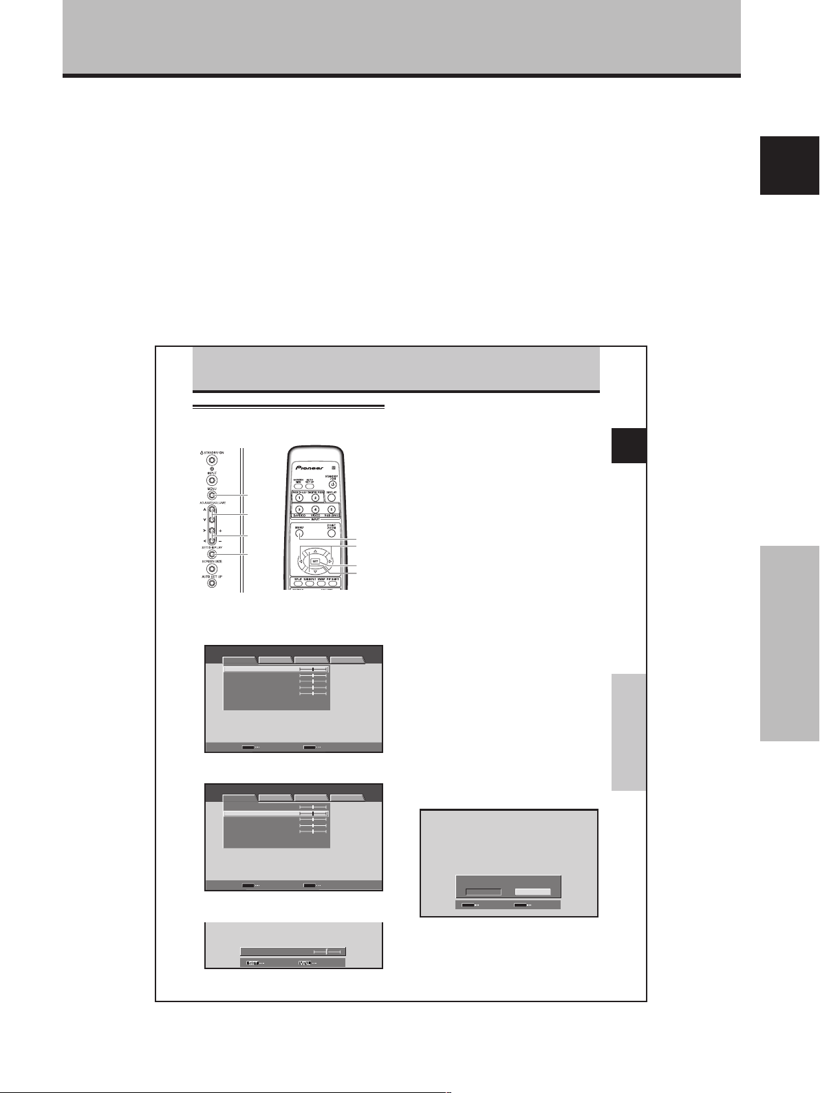
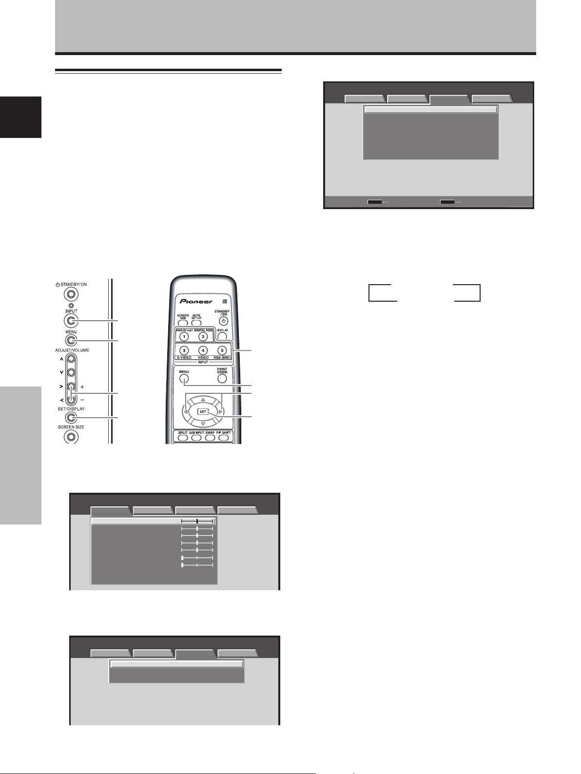
About operations in this manual
Each operation is described in its proper operating order.
These Operating Instructions will refer to the operating
controls found on the remote control unit, with the
exception of those buttons found only on the main
plasma display itself. When the plasma display controls
include equivalent buttons to those found on the remote
control unit, the commands can be performed on the
main unit as well.
Before Proceeding
English
The following illustrations are an example of the actual
operations used for the section “PICTURE adjustment”.
The examples are provided to allow you to confirm
whether the operation is performed correctly or not.
PICTURE/SCREEN Adjustment
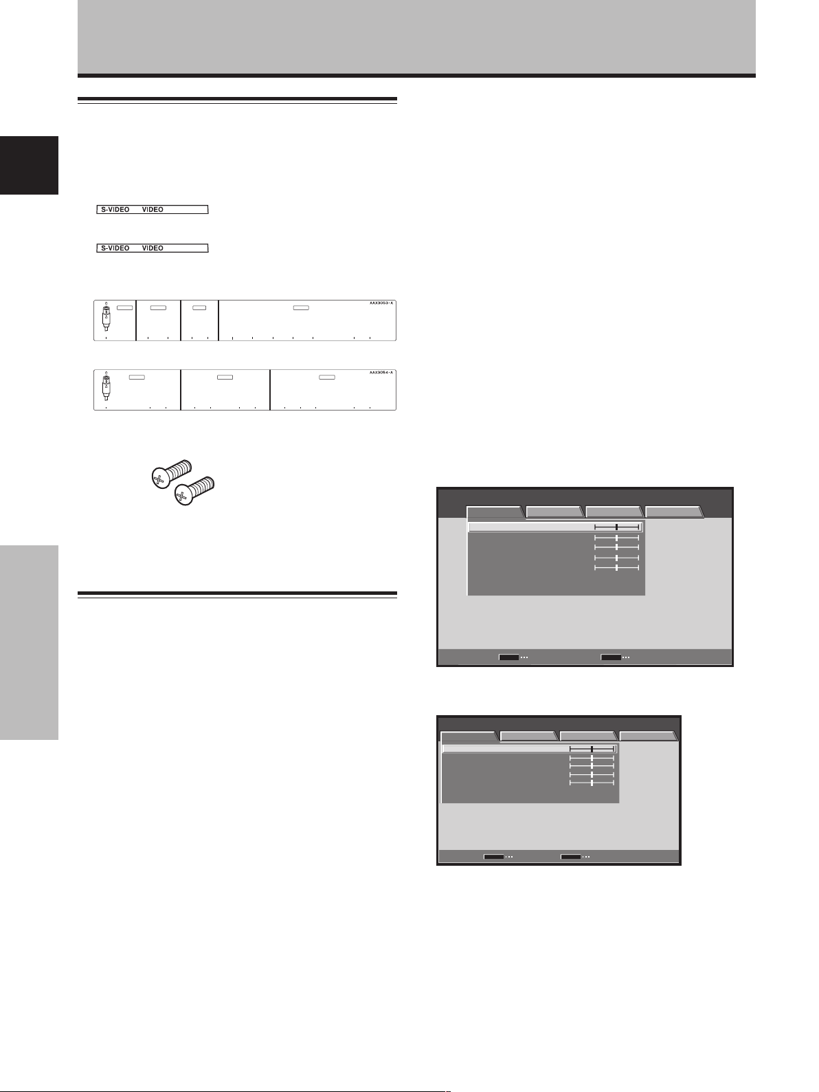
PICTURE adjustment
MENU
5/∞
2/3
SET
Display operating
panel
1 Press the MENU button to display the menu
screen.
MENU INPUT1
PICTURE SCREEN SETUP OPTION
CONTRAST
BRIGHTNESS
COLOR
TINT
SHARPNESS
PICTURE RESET
2 Use the 5/∞ buttons to select the adjustment
item, then press the SET button.
MENU INPUT1
PICTURE
CONTRAST
BRIGHTNESS
COLOR
TINT
SHARPNESS
PICTURE RESET
Remote control unit
:
0
:
0
:
0
:
0
:
0
SET
ENTER
MENU
SCREEN SETUP OPTION
:
0
:
0
:
0
:
0
:
0
MENU
2/3
SET
5/∞
EXIT
Note
The screen images depicted in these Operating Instructions
should be considered typical images; some difference will be
seen in practice, depending on the screen item displayed and its
contents, the input source and various other control settings.
4 Press the SET button.
Pressing the SET button writes the value into the
memory and returns the display to the step 2 screen.
5 When the setup is finished, press the MENU
button to exit the menu screen.
Note
Make these adjustments for each input (INPUT1 to INPUT5) and
signals.
[PICTURE] mode adjustment items
Below are brief descriptions of the options that can be set
in the [PICTURE] mode.
CONTRAST ············· Adjust according to the surrounding
BRIGHTNESS ·········· Adjust so that the dark parts of the
COLOR ···················· Adjust to the desired depth (Setting
TINT························· Adjust so that flesh tones look
SHARPNESS ··········· Normally set to the center position.
Note
Consult the Operating Instructions for your Plasma Display
regarding PICTURE adjustment when inputting computer signals.
To reset [PICTURE] mode settings to the default
If settings have been adjusted excessively or the picture
on the screen no longer appears natural, it may prove
more beneficial to reset the [PICTURE] mode to default
settings instead of trying to make adjustments under
already adjusted conditions.
1 In step 2 in the previous procedure, use the 5/∞
buttons to select [PICTURE RESET], then press the
SET button.
brightness so that the picture can be
seen clearly.
picture can be seen clearly.
to a slightly deep color will create a
natural looking picture).
normal.
To create a softer picture, set to the
left of center. To create a sharper
picture, set to the right of center.
English
PICTURE/SCREEN Adjustment
Before Proceeding
Part Names and Functions
SET
ENTER EXIT
3 Use the 2/3 buttons to adjust the picture quality
as desired.
BRIGHTNESS
MENU
:
SET EXIT
0
PICTURE RESET
YES
SET
SET
2 Use the 2/3 buttons to select [YES], and press
the SET button.
All [PICTURE] mode settings are returned to the
factory set default.
NO
MENU
EXIT
27
En
3
En
Page 7
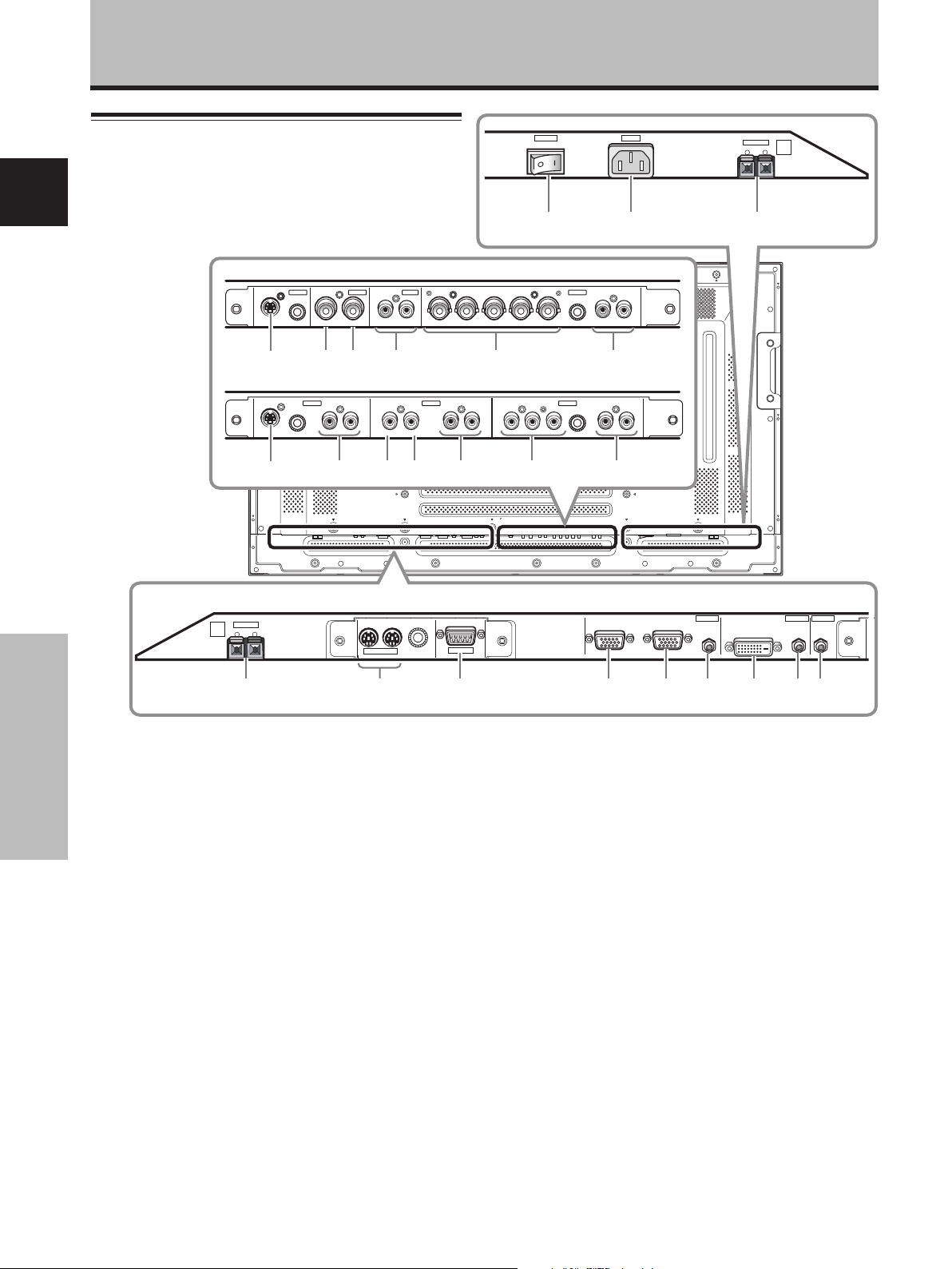
Part Names and Functions
Connection panel
English
Illustration depicts PDP-504CMX/
PDP-50MXE1/PDP-50MXE1-S model.
When installing PDA-5003
When installing PDA-5004
S-VIDEO
~
S-VIDEO
^
INPUT3
INPUT4
VIDEO
OUT R L
IN
! @
INPUT3 INPUT4 INPUT5
AUDIO AUDIO AUDIO
RL RL RLY Pb/Cb Pr/CrIN OUT
& ) _
AUDIO
INPUT 3/4 ANALOG RGB AUDIO
BR VD RL
G(ON SYNC)
#
VIDEO
* (
$
COMPONENT
VIDEO
OFF
HD (H/V SYNC)
POWER
ON
AC IN
SPEAKER
8Ω ~16Ω
+ –
L
=-0
INPUT5
%
+
SPEAKER
8Ω ~16Ω
R
+ –
IN OUT
COMBINATION
123 4 5 6
Plasma Display Section
The plasma display is provided with 2 video input
connectors, 1 video output connector, audio input/output
jacks and speaker terminals.
When this video card is installed on a plasma display, an
Part Names and Functions
additional three sets of video input connectors are provided
(total five), together with one additional video output
connector (total two). See the pages noted in parentheses
( ) or the plasma display’s Operating Instructions for details
regarding connections to the various jacks and connectors.
1 SPEAKER (R) terminal
For connection of an external right speaker.
Connect a speaker whose impedance is 8 -16 Ω.
2 COMBINATION IN/OUT
Never connect any component to these
connectors without first consulting your Pioneer
installation technician.
These connectors are used for plasma display setup
adjustments.
3 RS-232C
Never connect any component to this connector
without first consulting your Pioneer installation
technician.
This connector is used for plasma display setup
adjustments.
4
En
RS-232C
ANALOG RGB IN
D-Sub
ANALOG RGB OUT
INPUT1 INPUT2 OUTPUT
D-Sub
AUDIO AUDIO AUDIO
DIGITAL RGB
DVI-D
7 8 9
4 ANALOG RGB IN (INPUT1) (mini D-sub 15 pin)
For connecting components equipped with RGB
outputs jacks, such as a personal computer or external
RGB decoder; or components equipped with
component output jacks, such as a DVD recorder.
Make sure that the connection made corresponds to
the format of the signal output from the connected
component (pages 7 to 10).
5 ANALOG RGB OUT (INPUT1) (mini D-sub 15 pin)
Use the ANALOG RGB OUT (INPUT1) connector to
output the video signal to an external monitor or other
component.
Note: The video signal will not be output from the ANALOG
RGB OUT (INPUT1) connector when the main power of this
display is off or in standby mode (page 10).
6 AUDIO (INPUT1) (Stereo mini jack)
Use to obtain sound when INPUT1 is selected. Connect
this jack to the audio output connector of the device
connected to the plasma display’s INPUT1 (page 15).
7 DIGITAL RGB (INPUT2) (DVI-D jack)
Use to connect a computer.
Note: This unit does not support the display of
copyguard-protected video signals (page 13).
Page 8

Part Names and Functions
8 AUDIO (INPUT2) (Stereo mini jack)
Use to obtain sound when INPUT2 is selected. Connect
this jack to the audio output connector of the device
connected to the plasma display’s INPUT2 (page 15).
9 AUDIO (OUTPUT) (Stereo mini jack)
Use to output the audio of the selected source
component connected to the plasma display to an AV
amplifier or similar component.
Note: No sound is produced from the AUDIO (OUTPUT) jack
when the MAIN POWER switch is set to OFF or ON (standby)
(page 15).
0 MAIN POWER switch
Use to switch the main power of the plasma display
on and off.
- AC IN
A power cable is furnished with the plasma display;
connect one end of the power cable to this connector,
and the other end to a standard AC power source.
= SPEAKER (L) terminal
For connection of an external left speaker. Connect a
speaker that has an impedance of 8 -16 Ω.
Video Card <PDA-5003> Section
The video card is provided with 3 video input connectors,
1 video output connector, and 2 audio input connectors.
Consult the pages noted in parentheses ( ) for details
regarding connections to the various jacks and
connectors.
~ S-VIDEO (INPUT3) (S-video jack)
For connection of components that have an S-video
output jack such as a video deck, video camera, laser
disc player, or DVD recorder (page 13).
! VIDEO IN (INPUT4) (BNC jack)
For connection of components that have a composite
video output jack such as a video deck, video camera,
laser disc player, or DVD recorder (page 13).
@ VIDEO OUT (INPUT4) (BNC jack)
Use the VIDEO OUT (INPUT4) jack to output the video
signal to an external monitor or other component.
Note: The video signal will not be output from the VIDEO
OUT (INPUT4) jack when the main power of this display is off
or in standby mode (page 13).
# AUDIO R/L (INPUT3/4) (RCA Pin jacks)
Use to obtain sound when INPUT3 or INPUT4 is
selected. Connect these jacks to the audio output
connectors of components connected to the video
card’s INPUT3 or INPUT4 (page 16).
$ ANALOG RGB (INPUT5) (BNC jacks)
For connecting components equipped with RGB
outputs jacks, such as a personal computer or external
RGB decoder; or components equipped with
component output jacks, such as a DVD recorder.
Make sure that the connection made corresponds to
the format of the signal output from the connected
component (pages 7 to 10).
% AUDIO R/L (INPUT5) (RCA Pin jacks)
Use to obtain sound when INPUT5 is selected. Connect
these jacks to the audio output connectors of components
connected to the video card’s INPUT5 (page 15).
Video Card <PDA-5004> Section
The video card is provided with 3 video input connectors,
1 video output connector, and 3 audio input connectors.
Consult the pages noted in parentheses ( ) for details
regarding connections to the various jacks and
connectors.
^ S-VIDEO (INPUT3) (S-video jack)
For connection of components that have an S-video
output jack such as a video deck, video camera, laser
disc player, or DVD recorder (page 11).
& AUDIO R/L (INPUT3) (RCA Pin jacks)
Use to obtain sound when INPUT3 is selected. Connect
these jacks to the audio output connectors of components
connected to the video card’s INPUT3 (page 16).
* VIDEO IN (INPUT4) (RCA Pin jack)
For connection of components that have a composite
video output jack such as a video deck, video camera,
laser disc player, or DVD recorder (page 13).
( VIDEO OUT (INPUT4) (RCA Pin jack)
Use the VIDEO OUT (INPUT4) jack to output the video
signal to an external monitor or other component.
Note: The video signal will not be output from the VIDEO
OUT (INPUT4) jack when the main power of this display is off
or in standby mode (page 13).
) AUDIO R/L (INPUT4) (RCA Pin jacks)
Use to obtain sound when INPUT4 is selected. Connect
these jacks to the audio output connectors of components
connected to the video card’s INPUT4 (page 16).
_ COMPONENT VIDEO (INPUT5) (RCA Pin jacks)
For connection of components that have component
video output jacks such as a DVD recorder (pages 7
and 8).
+ AUDIO R/L (INPUT5) (RCA Pin jacks)
Use to obtain sound when INPUT5 is selected. Connect
these jacks to the audio output connectors of components
connected to the video card’s INPUT5 (page 15).
English
Part Names and Functions
5
En
Page 9
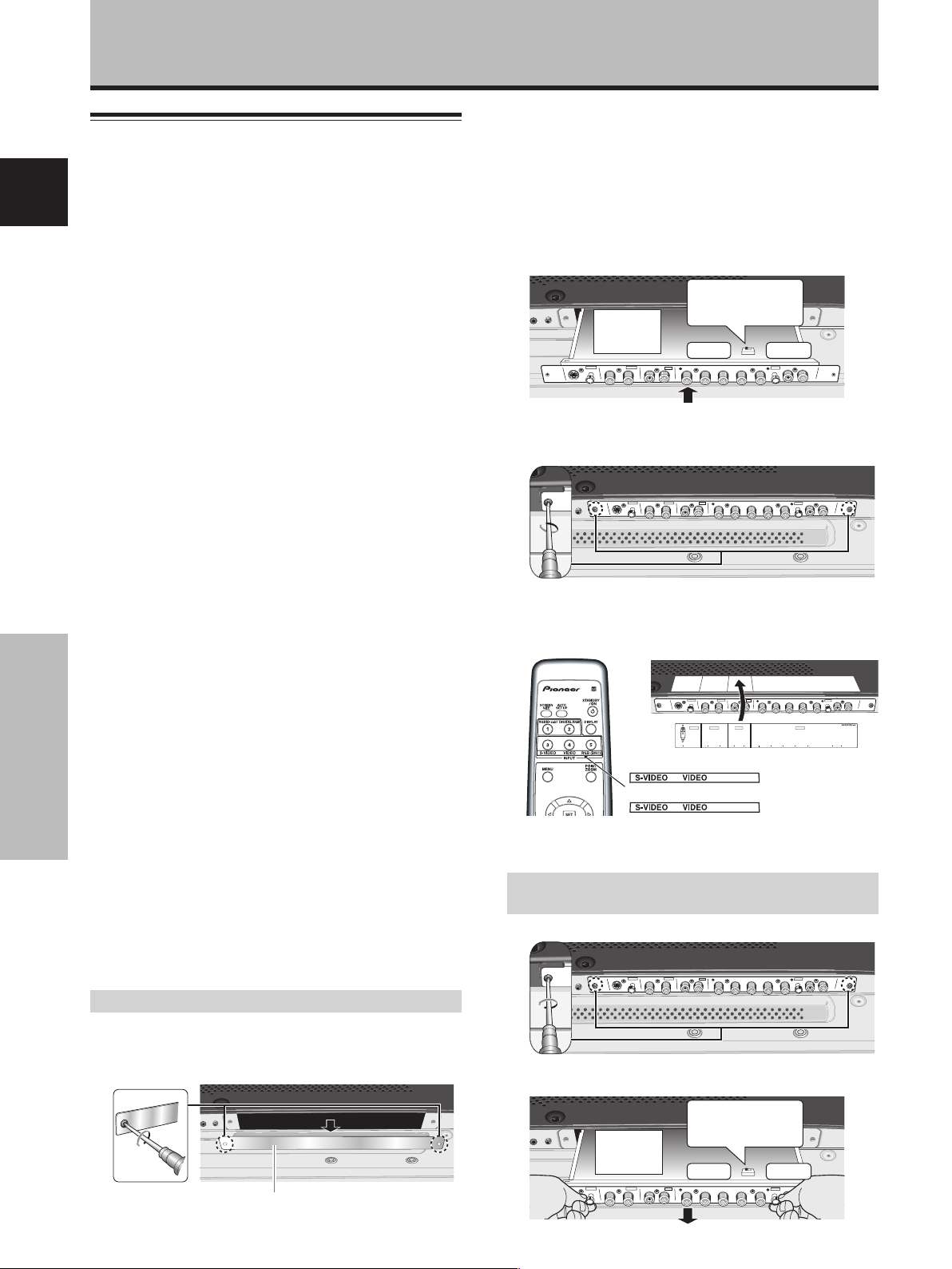
Installation and Connections
Installing the video card
TO USERS:
This component is sold with the understanding that it will be
English
installed by a specialist possessing appropriate technical
knowledge and ability.
TO SALES AGENTS:
Installation instructions are noted below. When installing the unit,
if a screw or other object should drop inside the plasma display,
immediately consult your nearest Pioneer Service Center.
Continuing operation may result in malfunction.
This device has been designed for installation on the Pioneer
Plasma Display PDP-504CMX/PDP-50MXE1/PDP-50MXE1-S or
PDP-434CMX/PDP-43MXE1/PDP-43MXE1-S. Installation
procedures are as follows:
Confirm the following before installing this video card:
• Disconnect the plasma display from computer or other
components.
• Disconnect the plasma display’s power cord from its outlet.
Installation Notes:
÷ When opening the protective cover, take care not to drop
screws or other objects in the opening. Objects dropped inside
the display may cause damage or malfunction.
÷ When installing the video card, if the plasma display is laid
with its screen side facing down, the work surface should be
flat and level, and either the packing material, a blanket, or
other soft material should be spread on the work surface first
to protect the screen. Take care to prevent scratches or other
damage to the unit from tools or other objects. Never rest the
display on a surface in such a way that weight or pressure is
placed only on the screen surface.
÷ This video card has been designed for exclusive use with the
Pioneer Plasma Display PDP-504CMX/PDP-50MXE1/PDP50MXE1-S or PDP-434CMX/PDP-43MXE1/PDP-43MXE1-S. Do
not attempt unauthorized modifications or alterations since
malfunction or damage may result.
÷ Take care not to modify or damage the card’s internal devices
in any way.
÷ Before installation, take precautions to eliminate static
Installation and Connections
electricity on your body. Do not touch the card’s circuitry or
devices.
÷ This device has not been designed to allow reinstallation or
removal; after the card has once been installed on the plasma
display, do not attempt to remove it since damage may result.
÷ When installing the PDA-5003, it may be necessary to adjust
the setting of the impedance selector switch. Confirm this
item before installing (pages 10, 12).
÷ Do not install the PDA-5002 on the PDP-504CMX/PDP-
50MXE1/PDP-50MXE1-S or PDP-434CMX/PDP-43MXE1/PDP43MXE1-S display units.
Installation
Illustration depicts PDA-5003 model.
1 Remove the protective cover over the video card
slot on the plasma display’s terminal panel.
2 Insert the video card gently and evenly in
alignment with the two rails visible inside the
installation port.
Notes
÷ Be very careful when inserting the card. Install the card’s
device mounting surface oriented toward the rear side of the
plasma display. Insert straight! The card or display may be
damaged if the card is inserted crooked or with excessive
force.
÷ Impedance selector switch is found on PDA-5003 only.
Impedance
Device
selector switch
mounting
surface
VIDEO
S-VIDEO INPUT3
3
After inserting the video card all the way into the
INPUT 3/4
INPUT4
75 Ω 2.2 kΩ
AUDIO
ANALOG RGB
HD (H/V SYNC)
AUDIO
INPUT5
slot, confirm that it is seated securely, then use the
screws removed in step 1 to secure the card in place.
VIDEO
S-VIDEO INPUT3
INPUT 3/4
INPUT4
ANALOG RGB
AUDIO
HD (H/V SYNC)
AUDIO
INPUT5
4 Affix the accessory connector indicator label to the
plasma display, and affix the remote control unit
label to the remote control unit furnished with the
plasma display.
VIDEO
S-VIDEO INPUT3
PDA-5003
PDA-5004
INPUT 3/4
INPUT4
AUDIO
INPUT4 INPUT5AUDIO
INPUT3
S-VIDEO
/
4 ANALOG RGB AUDIO
VIDEO INPUT3
IN OUT R L RLGBRHDVD
RGB (BNC)
COMPONENT
ANALOG RGB
(ON SYNC) (H/V SYNC)
AUDIO
INPUT5
HD (H/V SYNC)
Note
Use a soft cloth to gently wipe away any dust or soiling from the
surface before affixing the label.
Video Card Removal (In principle, removal of
the video card should not be attempted).
1 Remove the two screws holding the video card.
VIDEO
S-VIDEO INPUT3
INPUT 3/4
INPUT4
ANALOG RGB
AUDIO
HD (H/V SYNC)
AUDIO
INPUT5
2 Holding the inside tabs, pull the video card out
straight.
Impedance
selector switch
75Ω 2.2kΩ
AUDIO
ANALOG RGB
HD (H/V SYNC)
AUDIO
INPUT5
Protective cover
S-VIDEO INPUT3
Device
mounting
surface
VIDEO
INPUT4
INPUT 3/4
6
En
Page 10
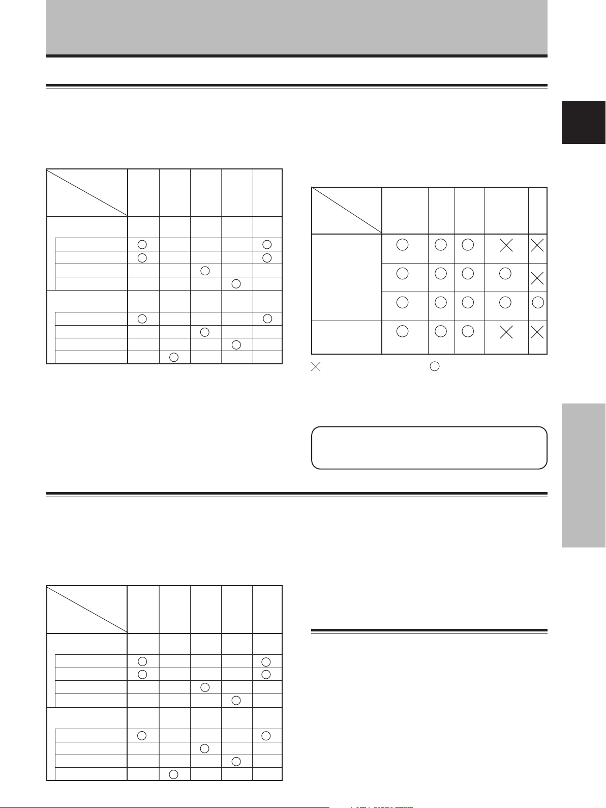
■ When using PDA-5003
Installation and Connections
Input connectors on the plasma
display with video card
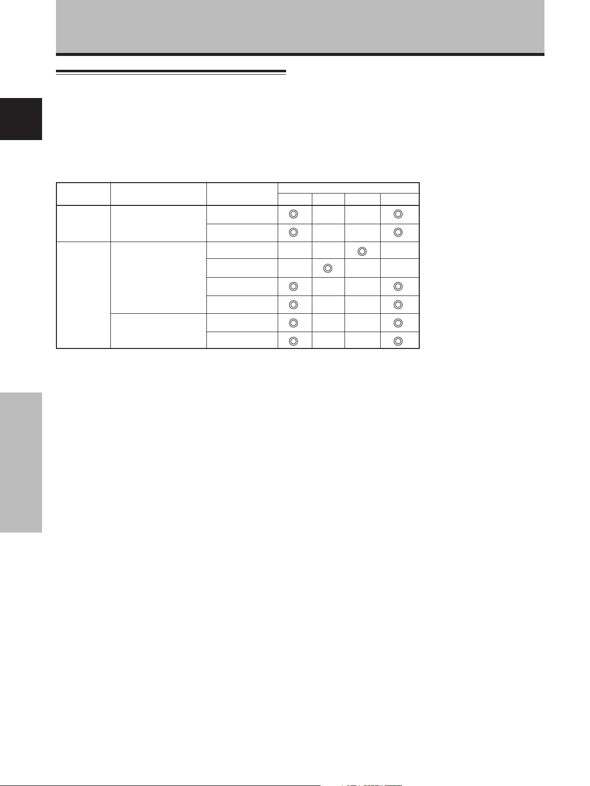
Consult the following chart when making connections to a
plasma display equipped with this video card (pages 7 to 16).
Input
Connected
component
and signals
AV component
Personal computer
(PC)
*1 Although INPUT1 and INPUT5 are compatible with various
*2 INPUT1 is compatible with Microsoft’s Plug & Play (VESA
*3 Depending on the video output board of the computer, this
*4 INPUT2 is compatible with Microsoft’s Plug & Play (VESA
Connector
Analog RGB
Component video
S video
Composite video
Analog RGB
S video
Composite video
Digital RGB
kinds of signals, setup using the on-screen menu is
necessary after connections are made in order match the
characteristics of the source component (pages 18 to 20).
DDC 1/2B).
type of connection may not be possible.
DDC 2B).
INPUT
*1
1
*2
INPUT
2
*4
INPUT
3
*3
INPUT
4
*3
INPUT
*1
5
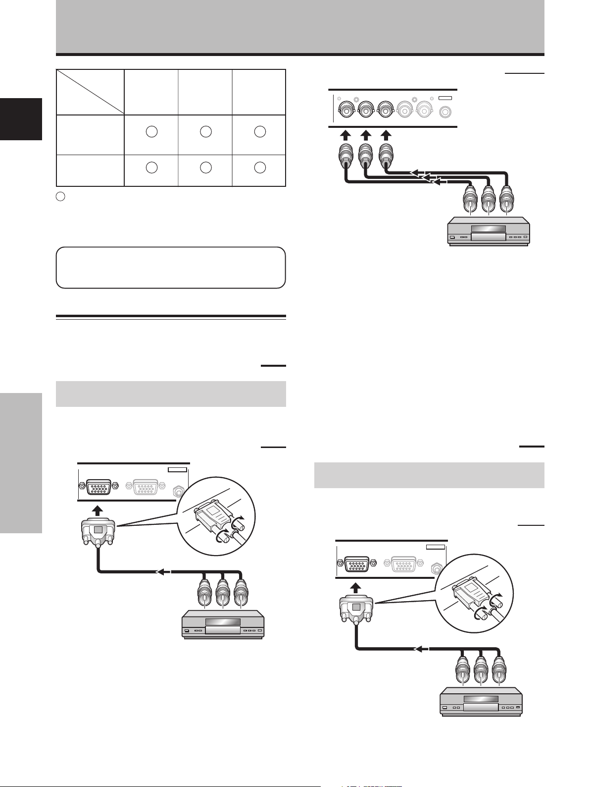
Connection to INPUT1 and INPUT5
Various components can be connected to the INPUT1 and
INPUT5 jacks. After connections are made, on-screen
setup is necessary to match the characteristics of the
connected component. Please see pages 18 to 20 for onscreen setup after connection.
INPUT5
jack
Output source
Video component/
personal
computer (PC)
with RGB output
Video component
with component
video output
: Do not connect anything. : Connect to this jack.
Note
Components compatible with INPUT1 are also compatible with
INPUT5. When making connections to INPUT1, please refer to
the plasma display’s Operating Instructions.
See Appendixes 1 and 2 (pages 43 to 45) for
information regarding signals and display formats
supported by INPUT1 and INPUT5.
[ON SYNC]
GBR
G ON SYNC
GBR
Y Pb/Cb Pr/Cr
R
B
RG
B
[H/V SYNC]
HD VD
H/V SYNC
HD
VD
English
■ When using PDA-5004
Input connectors on the plasma
display with video card
Consult the following chart when making connections to a
plasma display equipped with this video card (pages 7 to
16).
Input
Connected
component
and signals
AV component
Personal computer
(PC)
Connector
Analog RGB
Component video
S video
Composite video
Analog RGB
S video
Composite video
Digital RGB
INPUT
*1
1
*2
INPUT
2
*4
INPUT
3
*3
INPUT
4
*3
INPUT
*1
5
*1 Although INPUT1 and INPUT5 are compatible with various
kinds of signals, setup using the on-screen menu is
necessary after connections are made in order match the
characteristics of the source component (pages 18 to 20).
*2 INPUT1 is compatible with Microsoft’s Plug & Play (VESA
DDC 1/2B).
*3 Depending on the video output board of the computer, this
type of connection may not be possible.
*4 INPUT2 is compatible with Microsoft’s Plug & Play (VESA
DDC 2B).
Connection to INPUT1 and INPUT5
Various components can be connected to the INPUT1 and
INPUT5 jack. After connections are made, on-screen
setup is necessary to match the characteristics of the
connected component. Please see pages 18 to 20 for onscreen setup after connection.
Installation and Connections
7
En
Page 11
Installation and Connections
INPUT5
jack
Y
Pb/Cb
Output source
Video component/
English
personal
computer (PC)
with RGB output
G ON SYNC
B
Video component
with component
video output
Y
Pb/Cb
: Connect to this jack.
Note
When making connections to INPUT1, please refer to the plasma
display’s Operating Instructions.
See Appendixes 1 and 2 (pages 43 to 45) for
information regarding signals and display formats
supported by INPUT1.
Connection to INPUT1 or INPUT5
■ When using PDA-5003
Connection to AV components
Connection to AV component equipped with
component video jacks
Make component video connections for AV components
equipped with component video jacks.
When connecting to ANALOG RGB IN (INPUT1)
Pr/Cr
R
Pr/Cr
When connecting to ANALOG RGB (INPUT5)
ANALOG RGB
BR VDHD (H/V SYNC)G(ON SYNC)
INPUT5
Connect the Y signal to the G jack, the PB/CB signal to the
B jack, and the P
R/CR signal to the R jack.
On-screen setup is necessary after connection.
Please see pages 18 to 20.
INPUT5 jacks are all BNC jacks.
If necessary, use commercially available BNC/pin-plug
conversion adapters to make connections.
Note
The plasma display and this Video Card are designed to support
component video signals with standard, stable signal levels and
sync signals. As a result, some image disruption may be
generated during use of various special trick play functions on
video components.
■ When using PDA-5004
Connection to AV components
ANALOG RGB IN
D-Sub
ANALOG RGB OUT
D-Sub
INPUT1
AUDIO
IN
Installation and Connections
On-screen setup is necessary after connection.
Please see pages 18 to 20.
8
En
Connection to AV component equipped with
component video jacks
Make component video connections for AV components
equipped with component video jacks.
When connecting to ANALOG RGB IN (INPUT1)
ANALOG RGB IN
D-Sub
ANALOG RGB OUT
D-Sub
On-screen setup is necessary after connection.
Please see pages 18 to 20.
INPUT1
AUDIO
IN
Page 12
Installation and Connections
When connecting to COMPONENT VIDEO (INPUT5)
COMPONENT
VIDEO
Y Pb/Cb Pr/Cr
INPUT5
Connect the Y signal to the Y jack, the PB/CB signal to the
Pb/Cb jack, and the P
R/CR signal to the Pr/Cr jack.
Note
The plasma display and this Video Card are designed to support
component video signals with standard, stable signal levels and
sync signals. As a result, some image disruption may be
generated during use of various special trick play functions on
video components.
Connection of G ON SYNC analog RGB source
Make G ON SYNC connections for a component with
output that has the synchronization signal layered on top
of the green signal.
When connecting to ANALOG RGB IN (INPUT1)
When connecting to ANALOG RGB (INPUT5)
[Connections for PDA-5003]
ANALOG RGB
BR VDHD (H/V SYNC)G(ON SYNC)
INPUT5
On-screen setup is necessary after connection.
Please see pages 18 to 20.
Note
When making G ON SYNC connections, do not make any
connections to the VD or HD jacks. If connections are made, the
picture may be not displayed normally.
When connecting to COMPONENT VIDEO (INPUT5)
[Connections for PDA-5004]
COMPONENT
VIDEO
Y Pb/Cb Pr/Cr
INPUT5
English
ANALOG RGB IN
D-Sub
ANALOG RGB OUT
D-Sub
INPUT1
AUDIO
IN
On-screen setup is necessary after connection.
Please see pages 18 to 20.
Installation and Connections
Connect the G ON SYNC signal to the Y jack, the B signal
to the Pb/Cb jack, and the R signal to the Pr/Cr jack.
On-screen setup is necessary after connection.
Please see pages 18 to 20.
9
En
Page 13

Installation and Connections
Connection of composite SYNC analog RGB
source
Make composite SYNC connections for a component
with output that has the vertical synchronization signal
layered on top of the horizontal synchronization signal.
English
When connecting to ANALOG RGB IN (INPUT1)
ANALOG RGB IN
D-Sub
ANALOG RGB OUT
D-Sub
On-screen setup is necessary after connection.
Please see pages 18 to 20.
When connecting to ANALOG RGB (INPUT5)
[Connections for PDA-5003]
INPUT1
AUDIO
IN
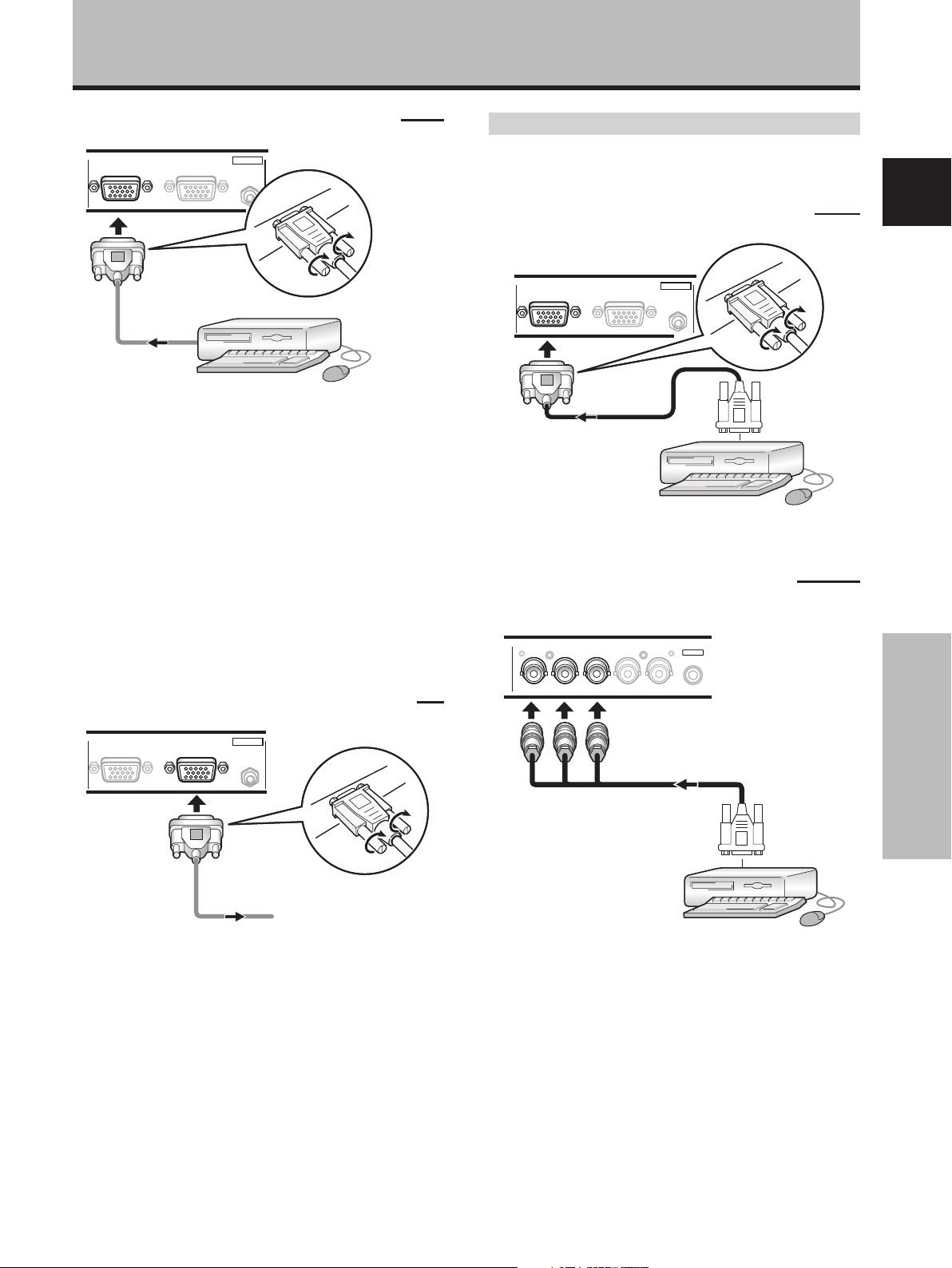
Connection to a personal
computer
Connection method differs depending on the computer
type. When connecting, please thoroughly read the
computer’s operating instructions.
Before making connections, be sure to make sure that
the personal computer’s power and display’s main power
is off.
For the PC input signals and screen sizes that the display
is compatible with, please refer to the plasma display’s
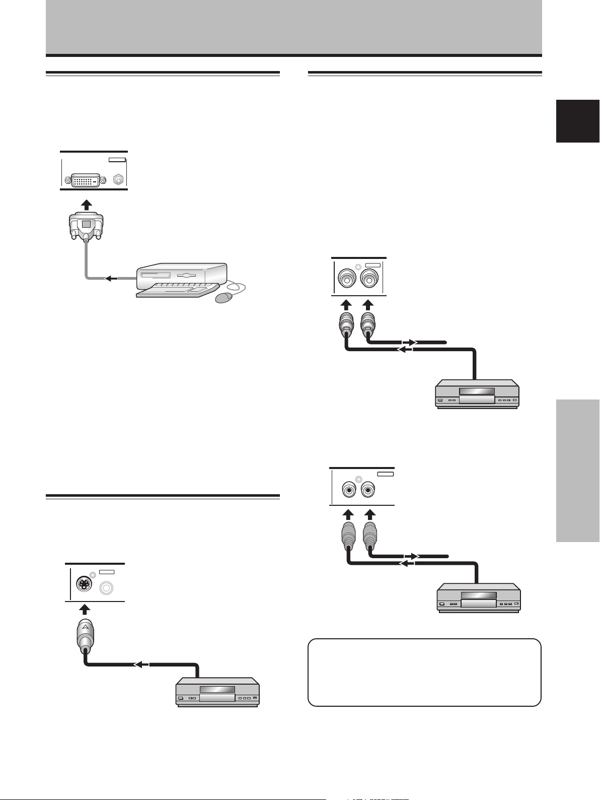
Operating Instructions.
Connection of separate SYNC analog RGB
source
Make separate SYNC connections for a personal
computer that has RGB output separated into 5 output
signals: green, blue, red, horizontal synchronization signal,
and vertical synchronization signal.
When connecting to ANALOG RGB (INPUT5)
[Connections for PDA-5003]
ANALOG RGB
BR VD
G(ON SYNC)
HD (H/V SYNC)
INPUT5
INPUT5
BR VD
G(ON SYNC)
ANALOG RGB
HD (H/V SYNC)
Installation and Connections
When using INPUT5, set the impedance selector switch
to match the output impedance of the connected
component’s synchronization signal.
When the output impedance of the sync signal is below
75 Ω remove the video card and set the impedance
selector switch to 75 Ω (page 6).
On-screen setup is necessary after connection.
Please see pages 18 to 20.
Note
When making composite SYNC connections, do not connect
anything to the VD jack. If connected to, the picture may not be
displayed properly.
When using INPUT5, set the impedance selector switch
to match the output impedance of the connected
computer’s synchronization signal.
When the output impedance of the sync signal is below
75 Ω remove the video card and set the impedance
selector switch to 75 Ω (page 6).
On-screen setup is necessary after connection.
Please see pages 18 to 20.
10
En
Page 14
Installation and Connections
When connecting to ANALOG RGB IN (INPUT1)
ANALOG RGB IN
D-Sub
ANALOG RGB OUT
D-Sub
INPUT1
AUDIO
Connect the cable corresponding to the shape of the
input terminal on the display and the personal computer’s
output terminal.
Secure by tightening the terminal screws on both units.
On-screen setup is necessary after connection.
Please see pages 18 to 20.
Note
Depending on the type of computer model being connected, a
conversion connector or adapter etc. provided with the computer
or sold separately may be necessary.
For details, please read your PC’s instruction manual or consult
the maker or nearest dealer of your computer.
When connecting to ANALOG RGB OUT (INPUT1)
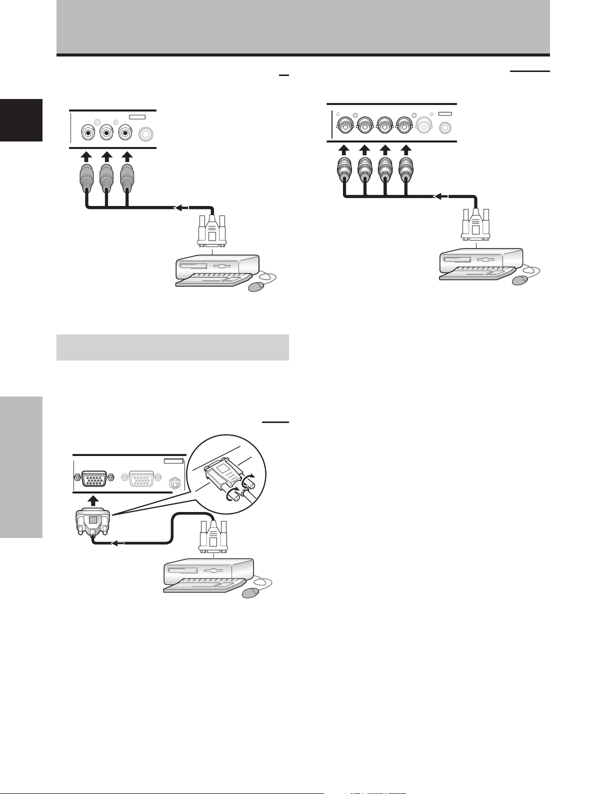
Connection of G ON SYNC analog RGB source
Make G ON SYNC connections for a personal computer
with output that has the synchronization signal layered on
top of the green signal.
When connecting to ANALOG RGB IN (INPUT1)
HD (H/V SYNC)
INPUT1
AUDIO
INPUT5
ANALOG RGB IN
D-Sub
ANALOG RGB OUT
D-Sub
On-screen setup is necessary after connection.
Please see pages 18 to 20.
When connecting to ANALOG RGB (INPUT5)
[Connections for PDA-5003]
ANALOG RGB
BR VD
G(ON SYNC)
English
ANALOG RGB IN
D-Sub
ANALOG RGB OUT
D-Sub
INPUT1
AUDIO
To an external monitor
With the plasma display, it is possible to output the video
signal to an external monitor or other component from
the ANALOG RGB OUT (INPUT1) terminal.
Note
A video signal will not be output from the ANALOG RGB OUT
(INPUT1) terminal when the main power of this unit is off or in
standby.
Installation and Connections
On-screen setup is necessary after connection.
Please see pages 18 to 20.
Note
When making G ON SYNC connections, do not make any
connections to the VD or HD jacks. If connections are made, the
picture may be not displayed normally.
11
En
Page 15
Installation and Connections
When connecting to COMPONENT VIDEO (INPUT5)
[Connections for PDA-5004]
COMPONENT
VIDEO
INPUT5
English
Y Pb/Cb Pr/Cr
On-screen setup is necessary after connection.
Please see pages 18 to 20.
Connection of composite SYNC analog RGB
source
Make composite SYNC connections for a personal
computer with output that has the vertical
synchronization signal layered on top of the horizontal
synchronization signal.
When connecting to ANALOG RGB IN (INPUT1)
ANALOG RGB IN
D-Sub
ANALOG RGB OUT
D-Sub
INPUT1
AUDIO
When connecting to ANALOG RGB (INPUT5)
[Connections for PDA-5003]
INPUT5
BR VD
G(ON SYNC)
ANALOG RGB
HD (H/V SYNC)
When using INPUT5, set the impedance selector switch
to match the output impedance of the connected
computer’s synchronization signal.
When the output impedance of the sync signal is below
75 Ω remove the video card and set the impedance
selector switch to 75 Ω (page 6).
On-screen setup is necessary after connection.
Please see pages 18 to 20.
Notes
÷ When making composite SYNC connections, do not connect
anything to the VD jack. If connected to, the picture may not
be displayed properly.
÷ Some types of computer devices manufactured by Apple
Computer, Inc. are equipped with both G ON SYNC and
composite SYNC outputs. This type of component should be
connected using the G ON SYNC connection (page 11).
Installation and Connections
On-screen setup is necessary after connection.
Please see pages 18 to 20.
12
En
Page 16
Installation and Connections
Connection to INPUT2
A computer equipped with DVI output (digital RGB signal)
can be connected to the plasma display’s DVI connector.
DVI-D
INPUT2
AUDIO
Personal computer
DIGITAL RGB
On-screen setup is necessary after connection.
Please see pages 18 to 20.
Notes
¶ Use a DVI-D 24-pin (digital only) cable for the connection.
¶ This unit does not support the display of copyguard-
protected video signals.
Connection to INPUT4
Connect an AV component that has a video output jack to
the video card’s INPUT4 jack. The VIDEO OUT (INPUT4)
jack can be used to output the video signal to a separate
monitor, recording device or other component with video
input capability.
Note
A video signal will not be output from the VIDEO OUT (INPUT4)
jack when the main power of this display is off or in standby
mode.
[When using PDA-5003]
INPUT4
VIDEO
OUT
IN
To a monitor or a
recording device
English
NOTICE
¶ INPUT2 is compatible with Microsoft’s Plug & Play (VESA DDC
2B).
¶ For the screen sizes and input signals that INPUT2 is
compatible with, please refer to the plasma display’s Operating
Instructions.
Connection to INPUT3
Connect an AV component that has S-video output jack to
the video card’s S-VIDEO (INPUT3) jack.
INPUT3
S-VIDEO
AV component
AV component
[When using PDA-5004]
VIDEO
IN OUT
INPUT4
To a monitor or a
recording device
AV component
Signals to the INPUT3 and INPUT4 jacks are all
compatible with the following TV systems: NTSC, PAL,
SECAM, 4.43NTSC, PAL M and PAL N. For details,
please refer to “Setting the COLOR SYSTEM” on page
39.
Installation and Connections
13
En
Page 17
Installation and Connections
About DTV set top box connection
To ensure proper connection, please carefully read the
instruction manual supplied with the DTV set top box.
English
The set top box output signals that this display is
compatible with are as follows.
Video
signal type
HDTV
SDTV
Video signal
1125i (1080i)
750p (720p)
525i (480i)
625i (575i)
525p (480p)
625p (575p)
Video
signal format
Component
RGB
Composite
S Video
Component
RGB
Component
RGB
Jacks where connection is possible
INPUT1
INPUT3
INPUT5INPUT4
Installation and Connections
14
En
Page 18
Audio connections
Installation and Connections
Audio connections for component connected to
INPUT2
Before making connections, be sure to check that the
audio component’s power and the display’s main power is
off.
Connect an audio component to the audio input
jack of the plasma display with installed video
card.
When the video card is installed, the plasma display
provides four or five audio input jacks and one audio
output jack. Consult the following chart to choose the
proper audio input for each video input.
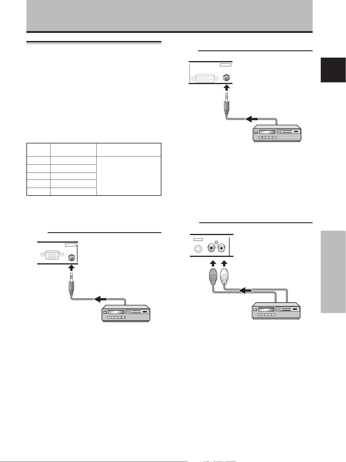
Video
input
INPUT1
INPUT2
INPUT5
INPUT3
INPUT4
*1
When using the PDA-5003, the INPUT3 and INPUT4
audio input connectors are shared.
Audio connection for component connected to
INPUT1
ANALOG RGB OUT
Audio input Sound output
Stereo mini jack (L/R)
Stereo mini jack (L/R)
Pin jacks (L/R)
Pin jacks (L/R)
Pin jacks (L/R)
D-Sub
INPUT1
AUDIO
IN
Sound of the selected video
input is output from the
• SPEAKER (L/R) terminals
*1
• Stereo mini jack (L/R).
*1
DIGITAL RGB
DVI-D
INPUT2
AUDIO
IN
A stereo miniplug cable can be used to connect the audio
output from the component connected to INPUT2, to the
plasma display’s AUDIO (INPUT2) jack (L/R).
Sound is output from both the AUDIO (OUTPUT) stereo
mini jack (L/R) and the SPEAKER (L/R) terminals according
to the video input selection.
Audio connection for component connected to
INPUT5
INPUT5
AUDIO
RL
English
A stereo miniplug cable can be used to connect the audio
output from the component connected to INPUT1, to the
plasma display’s AUDIO (INPUT1) jack (L/R).
Sound is output from both the AUDIO (OUTPUT) stereo
mini jack (L/R) and the SPEAKER (L/R) terminals according
to the video input selection.
Installation and Connections
The audio line for the component connected to INPUT5
can be connected to the AUDIO R/L (INPUT5) pin jacks.
Sound is output from both the AUDIO (OUTPUT) stereo
mini jack (L/R) and the SPEAKER (L/R) terminals according
to the video input selection.
15
En
Page 19
Installation and Connections
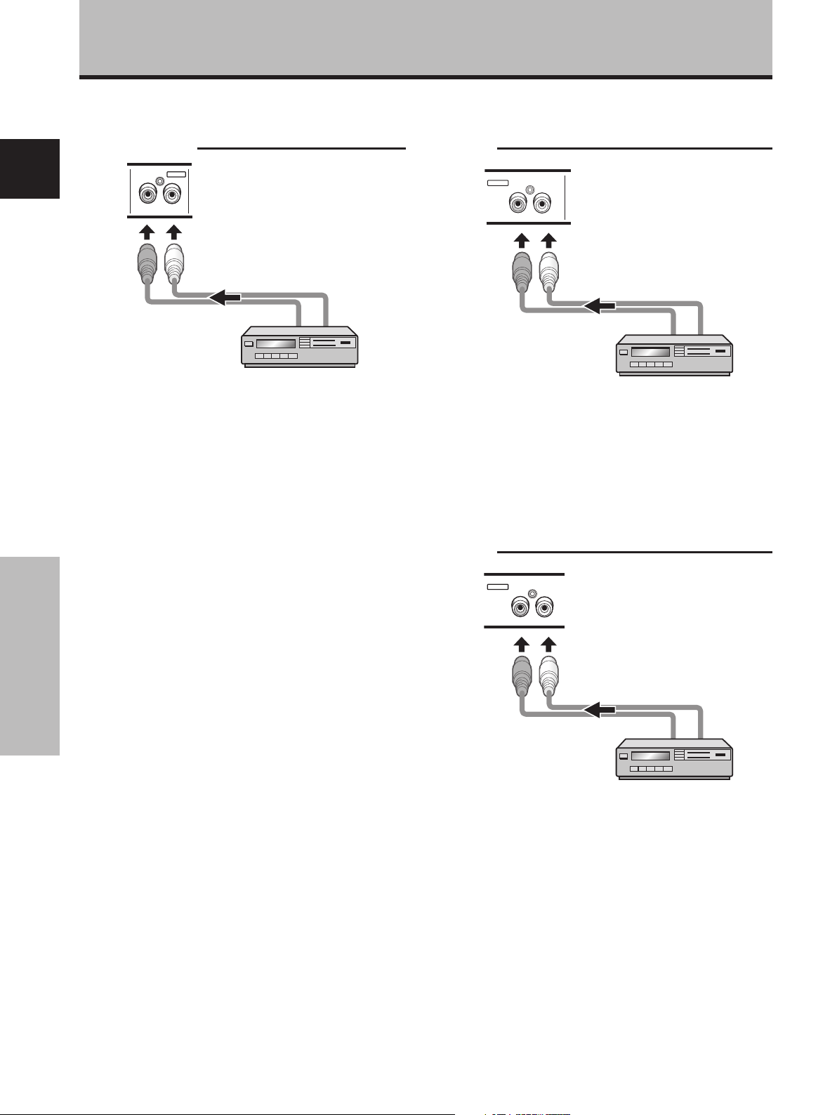
[When using PDA-5003]
Audio connection for component connected to
INPUT3 or INPUT4
AUDIO
English
INPUT 3/4
RL
Audio input to the AUDIO R/L (INPUT3/4) pin jacks is
possible for a component connected to either INPUT3 or
INPUT4.
Sound is output from both the AUDIO (OUTPUT) stereo
mini jack (L/R) and the SPEAKER (L/R) terminals according
to the video input selection.
[When using PDA-5004]
Audio connection for component connected to
INPUT3
INPUT3
AUDIO
RL
The audio line for the component connected to INPUT3
can be connected to the AUDIO R/L (INPUT3) pin jacks.
Sound is output from both the AUDIO (OUTPUT) stereo
mini jack (L/R) and the SPEAKER (L/R) terminals according
to the video input selection.
Installation and Connections
Audio connection for component connected to
INPUT4
INPUT4
AUDIO
RL
The audio line for the component connected to INPUT4
can be connected to the AUDIO R/L (INPUT4) pin jacks.
Sound is output from both the AUDIO (OUTPUT) stereo
mini jack (L/R) and the SPEAKER (L/R) terminals according
to the video input selection.
16
En
Page 20
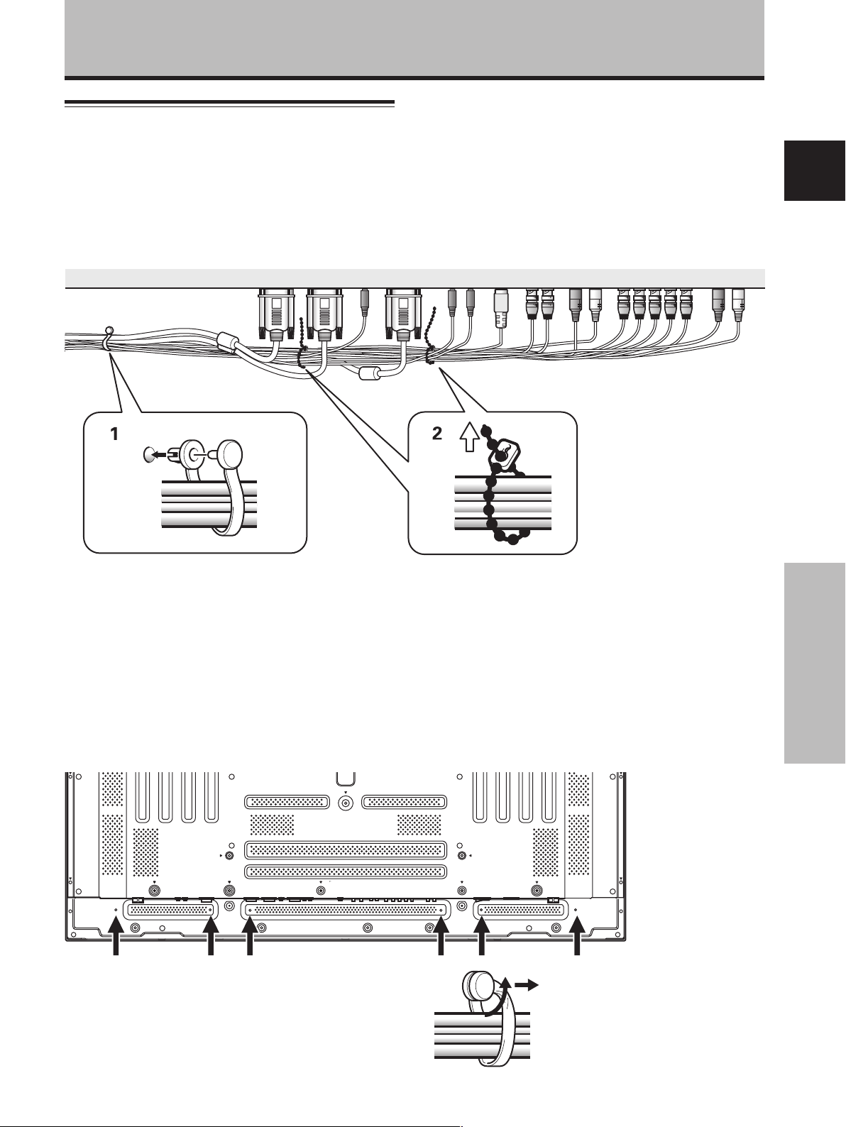
How to route cables
Speed clamps and bead bands are included with the
plasma display for bunching cables together. Once
components are connected, follow the following steps to
route cables.
The illustration depicts the PDP-504CMX/PDP-50MXE1/
PDP-50MXE1-S with video card PDA-5003.
2
1
Installation and Connections
English
* As viewed from the rear of the display.
1 Organize cables together using the provided
speed clamps.
Insert 1 into an appropriate hole on the rear of the
unit, then snap 2 into the back of 1 to fix the clamp.
Speed clamps are designed to be difficult to undo
once in place. Please attach carefully.
To attach the speed clamps to the display
Connect the speed clamps using the 6 holes marked
with “‡” below, depending on the situation.
To remove speed clamps
Using pliers, twist the clamp 90° and pull it outward.
In some cases the clamp may have deteriorated over time
and may be damaged when removed.
2 Bunch separated cables together and secure them
with the provided bead bands.
Do not allow excessive stress to be placed on the
ends of cables.
Note
Cables can be routed to the right or left.
The illustration depicts the PDP-504CMX/PDP-50MXE1/
PDP-50MXE1-S with video card PDA-5003.
* As viewed from the rear
of the display.
Installation and Connections
17
En
Page 21
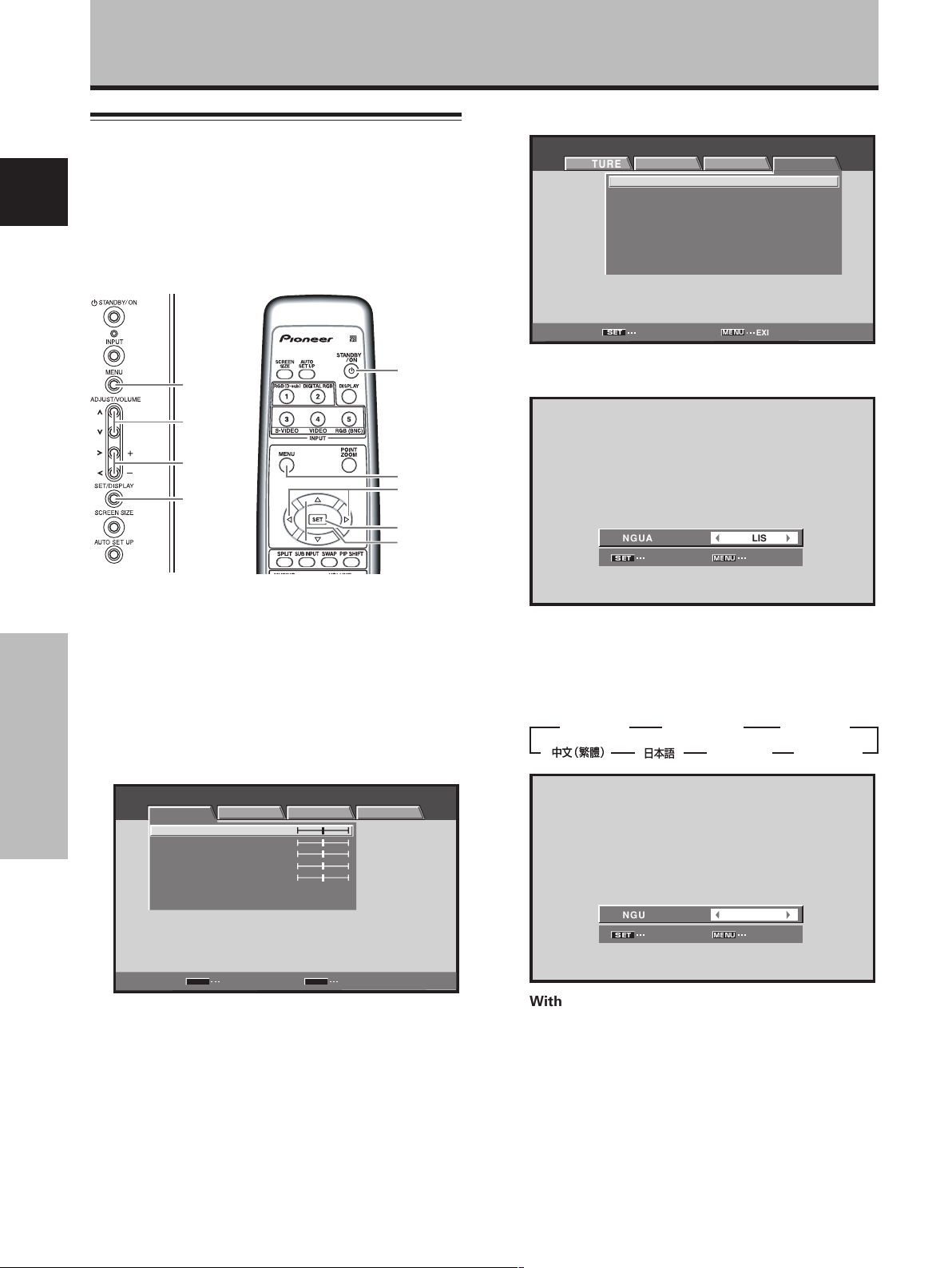
System Settings
Setting the onscreen display
language
English
The onscreen display language has been set to English as
the factory default. To change to another language, the
screen setting must be changed. Follow the procedures
below to change the setting.
4 Use the 2/3 buttons to select [OPTION].
MENU INPUT1
PICTURE SCREEN SETUP OPTION
LANGUAGE ENGLISH
ENERGY SAVE
SCREEN MGT.
ORBITER OFF
MASK CONTROL ON
AUTO SET UP MODE INACTIVE
AUTO FUNCTION OFF
AUDIO OUT FIXED
:
:
STANDARD
:
OFF
:
:
:
:
:
MENU
5/∞
2/3
SET
Display operating
Remote control unit
panel
1 Set the rear panel MAIN POWER switch to ON.
The STANDBY indicator on the front panel will light
red.
2 Press the STANDBY/ON button to turn the power
ON.
The ON indicator on the front panel will light green.
3 Press the MENU button to display the menu
screen.
System Settings
MENU INPUT1
PICTURE SCREEN SETUP OPTION
CONTRAST
BRIGHTNESS
COLOR
TINT
SHARPNESS
PICTURE RESET
:
0
:
0
:
0
:
0
:
0
STANDBY/
ON
MENU
2/3
SET
5/∞
SET
ENTER
MENU
EXIT
5 Use the 5/∞ buttons to select [LANGUAGE], then
press the SET button.
LANGUAGE
SET
SET
:
ENGLISH
MENU
EXIT
6 Use the 2/3 buttons to select the desired
language.
Each time the 2/3 buttons are pressed, the language
alternates between those available, in the following
order:
3
ENGLISH
3 2 3
2
LANGUAGE
SET
SET
3
FRANÇAIS
3
ITALIANO
:
MENU
2 3
23 2
ENGLISH
EXIT
ESPAÑOL
DEUTSCH
2
2
18
En
SET
ENTER
MENU
EXIT
7 With the desired language displayed, press the
SET button.
The selected language will be set in memory, and the
screen will return to that shown in step 4.
8 When settings are completed, press the MENU
button to return to the normal screen image.
Note
When the onscreen display language is set to any of INPUT 1 to
INPUT 5, the same display language will be set, regardless of the
type of input.
Page 22
Settings after connections
After components have been connected to INPUT1,
INPUT2 or INPUT5, on-screen setup is necessary.
Follow the procedure described below and make settings
as they apply to the type of components connected.
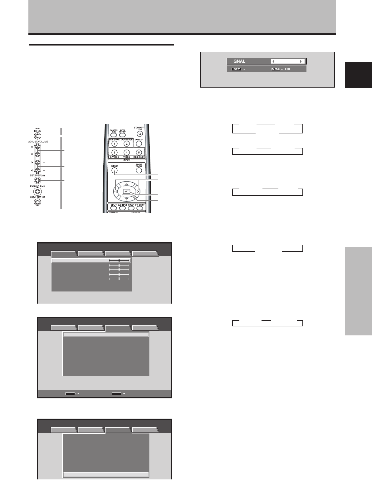
[SIGNAL FORMAT] /
[COLOR DECODING] setup
MENU
5/∞
System Settings
5 Use the 2/3 buttons to select the display mode.
SIGNAL FORMAT
SET
SET
1 When the input signal has a refresh rate of 31.5 kHz
horizontal / 60 Hz vertical, pressing 2/3 will cause
the display mode to change alternately as follows:
When using INPUT1 or INPUT5:
3 525p 2
When using INPUT2:
3 VGA 2 3 WVGA 2
:
MENU
3 VGA 2
3 WVGA 2
VGA
EXIT
English
2/3
MENU
SET
2/3
SET
5/∞
Display operating panel Remote control unit
1 Select INPUT1, INPUT2 or INPUT5.
2 Press the MENU button to display the menu screen.
MENU INPUT1
PICTURE SCREEN SETUP OPTION
CONTRAST
BRIGHTNESS
COLOR
TINT
SHARPNESS
PICTURE RESET
:
0
:
0
:
0
:
0
:
0
3 Use the 2/3 buttons to select [SETUP].
MENU INPUT1
PICTURE SCREEN SETUP OPTION
MENU
:
:
:
:
:
MIDDLE
:
:
MIDDLE
:
:
OFF
RGB
AUTO
:
:
VGA
AUTO POWER OFF DISABLE
COLOR TEMP.
DNR
MPEG NR LOW
CTI ON
PURECINEMA
COLOR DECODING
CLAMP POSITION
SIGNAL FORMAT
SET
CHANGE EXIT
4 Use the 5/∞ buttons to select [SIGNAL FORMAT],
then press the SET button.
MENU INPUT1
PICTURE SCREEN SETUP OPTION
:
AUTO POWER OFF
COLOR TEMP.
DNR
MPEG NR LOW
CTI ON
PURECINEMA
COLOR DECODING
CLAMP POSITION
SIGNAL FORMAT
DISABLE
:
MIDDLE
:
:
MIDDLE
:
:
:
OFF
:
RGB
:
AUTO
:
:
VGA
2 When providing input signals with refresh rates of
45 kHz horizontal / 60 Hz Vertical, pressing the 2/3
buttons causes the display mode to alternate as
follows:
÷ [720-PC] indicates resolution of 1280 x 720.
3 720-PC 2 3 750p 2
3 When the input signal has a refresh rate of 48.4
kHz horizontal / 60 Hz vertical, or 56.1 kHz
horizontal / 70 Hz vertical, pressing 2/3 will cause
the display mode to change alternately as follows:
3 XGA 2 3 WXGA 2
3 PC AUTO 2
If the [PC AUTO] setting is selected, screen
resolution will automatically switch between [XGA]
and [WXGA] as required.
4 When the input signal has a refresh rate of 64 kHz
horizontal / 60 Hz vertical, 80 kHz horizontal / 75 Hz
vertical, or 91.2 kHz horizontal / 85 Hz vertical,
pressing 2/3 will cause the display mode to
change alternately as follows:
3 SXGA 2 3 SXGA+ 2
Notes
÷ These settings are required only when providing input signals
with the following refresh rates: 1 31.5 kHz horizontal / 60 Hz;
2 45 kHz horizontal / 60 Hz vertical; 3 48.4 kHz horizontal / 60
Hz vertical or 56.1 kHz horizontal / 70 Hz vertical; 4 64 kHz
horizontal / 60 Hz vertical; 80 kHz horizontal / 75 Hz vertical or
91.2 kHz horizontal / 85 Hz vertical. Adjustment for other signal
frequency formats is performed automatically, so no manual
setting is required (the [SIGNAL FORMAT] message does not
appear).
÷ The [PC AUTO] setting supports automatic signal selection
only when using RGB separate SYNC inputs.
÷ When G ON SYNC or Composite SYNC signals are input,
selecting [PC AUTO] will cause the screen resolution to be set
to [XGA] only.
÷ When using G ON SYNC or Composite SYNC with WXGA
inputs, set [SIGNAL FORMAT] manually to [WXGA].
6 Press the SET button.
The setting is stored in memory and the screen
returns to that shown in step 4.
19
System Settings
En
Page 23
System Settings
7 When a component other than a computer is
connected, use the 5/∞ buttons to select [COLOR
DECODING] (INPUT1 or INPUT5).
MENU INPUT1
English
PICTURE SCREEN SETUP OPTION
AUTO POWER OFF
COLOR TEMP.
DNR
MPEG NR LOW
CTI ON
PURECINEMA
COLOR DECODING
CLAMP POSITION
SIGNAL FORMAT
:
DISABLE
:
MIDDLE
:
:
MIDDLE
:
:
:
OFF
:
RGB
:
AUTO
:
:
VGA
8 Press the SET button repeatedly to select the
input signal format.
Selection will change as follows each time the SET
button is pressed:
3 RGB
3 COMPONENT1
COMPONENT22
The table below shows what settings are appropriate
and available for the type of connections made.
Set [SIGNAL FORMAT] and [COLOR DECODING] as follows.
Please take care when making settings. Incorrect settings
can adversely affect the plasma display.
Connected
component
Component video output
of a DVD player, etc.
Component video output
from digital tuner, etc.
RGB video output of a
video deck etc., with RGB
output
RGB video output of a PC
System Settings
SETUP
SIGNAL
FORMAT
525p
750p
525p
VGA, WVGA,
720-PC,
XGA, WXGA,
SXGA, SXGA+
COLOR
DECODING
COMPONENT1
COMPONENT2
RGB
Not supported
9 When the setup is completed, press MENU to exit
the menu screen.
Notes
÷ Make this [SIGNAL FORAMT] setting for each applicable input
(INPUT1, INPUT2 or INPUT5).
÷ Make [COLOR DECODING] settings individually for INPUT 1 or
INPUT 5.
÷ The [COLOR DECODING] setting is not supported when
inputting a computer signal, or when the [SIGNAL FORMAT]
function has been used to select a signal other than [525p] or
[750p].
20
En
[CLAMP POSITION] setup
Depending on the signal, analog RGB signals may result
in the screen image appearing with a whitish or greenish
cast. In such cases, set [CLAMP POSITION] to [LOCKED].
Normally, leave this setting at [AUTO].
MENU
5/∞
MENU
2/3
SET
Display operating panel Remote control unit
1
Press the MENU button to display the menu screen.
MENU INPUT1
PICTURE SCREEN SETUP OPTION
CONTRAST
BRIGHTNESS
R.LEVEL
G.LEVEL
B.LEVEL
H.ENHANCE
V.ENHANCE
PICTURE RESET
:
0
:
0
:
0
:
0
:
0
:
0
:
0
2 Use the 2/3 buttons to select [SETUP].
MENU INPUT1
PICTURE SCREEN SETUP OPTION
POWER MANAGEMENT
CLAMP POSITION
SIGNAL FORMAT
3
Use the 5/∞ buttons to select [CLAMP POSITION].
MENU INPUT1
PICTURE SCREEN SETUP OPTION
POWER MANAGEMENT
CLAMP POSITION
SIGNAL FORMAT
:
OFF
:
AUTO
:
:
V
:
OFF
:
AUTO
:
V
GA
GA
4 Press the SET button to select [LOCKED].
MENU INPUT1
PICTURE SCREEN SETUP OPTION
POWER MANAGEMENT
CLAMP POSITION
SIGNAL FORMAT
:
OFF
:
LOCKED
:
V
GA
The factory default setting is [AUTO].
Mode selection will change as follows each time the
SET button is pressed:
3 AUTO
LOCKED 2
5 When the setup is completed, press the MENU
button to exit the menu screen.
Notes
÷ Make this [CLAMP POSITION] setting for each applicable input
(PDA-5003: INPUT1 or INPUT5, PDA-5004: INPUT1).
÷ When using this setup, be sure to carefully check the signal
output of the component that you are using. For details, please
refer to the instruction manual supplied with the component
you are connecting.
2/3
SET
5/∞
Page 24
Operation
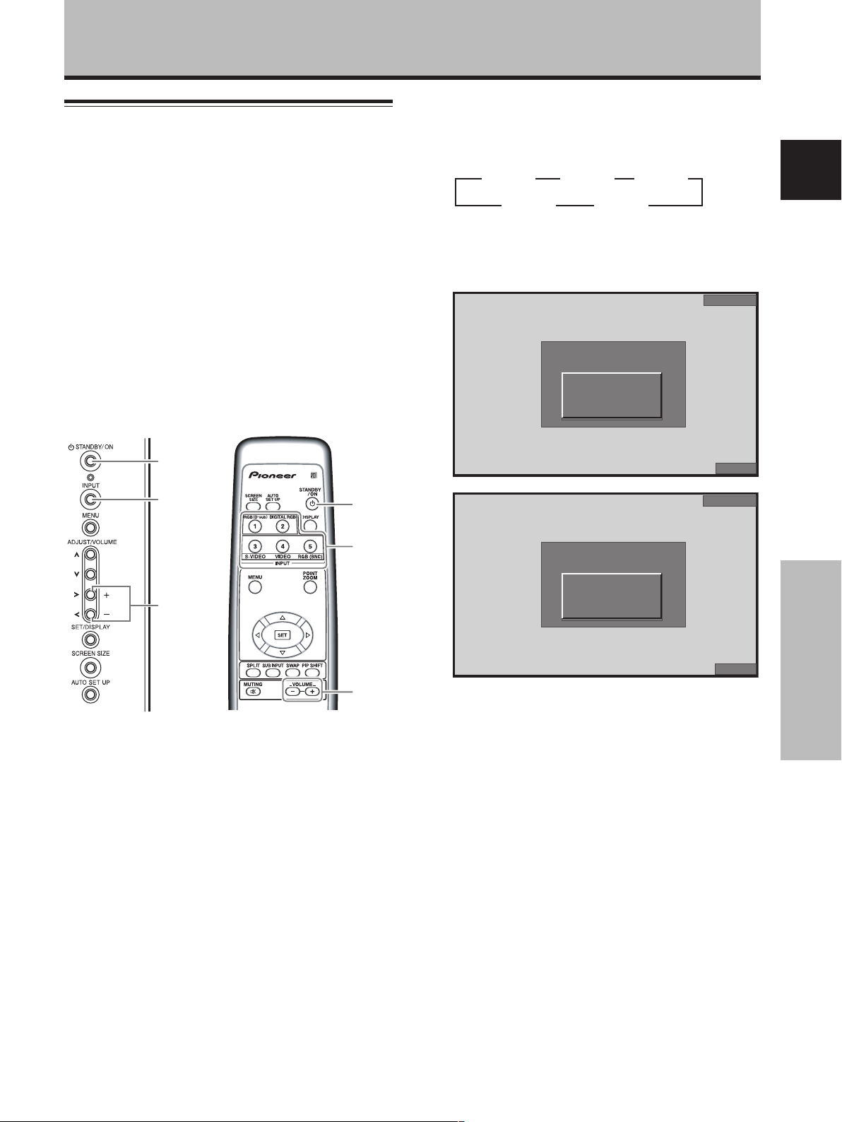
Selecting input source
This section explains the basic operation of the plasma
display. Outlined on the following pages is how to turn
the main power on and off, put this display in the
operation or standby mode and how to select connected
components.
Before you begin, make sure you have:
•
Made connections between the plasma display and AV
components or personal computer as described in the
section “Installation and Connections” starting on page 6.
• Set up the on-screen menu to input signals from
components connected to INPUT1, INPUT2 and
INPUT5 as described in the section “System Settings”
starting on page 18.
If no connections are made to these terminals,
on-screen setup is not necessary.
3 Press the INPUT button on the remote control unit
or the display to select the input.
Input changes each time the display’s INPUT button is
pressed as follows:
3 INPUT1
INPUT5 2
• When the menu screen is displayed, changing the
signal input will cause the menu screen to turn off.
• If the input computer signal is not supported by the
display, the following message will be displayed:
3 INPUT2 3 INPUT3
INPUT4 2
CAUTION
UNSUPPORTED SIGNAL
:
k
7816
:
512 684
HzfH .
HzfV .
588
X
INPUT1
English
STANDBY/
ON
STANDBY/
ON
INPUT
VOLUME
[+/–]
panel
INPUT
VOLUME
[+/–]
Remote control unitDisplay operating
1 Set the rear panel MAIN POWER switch to ON.
The STANDBY indicator on the front panel will light
red.
2 Press the STANDBY/ON button to turn the power
ON.
The ON indicator on the front panel will light green.
FULL
INPUT1
CAUTION
OUT OF RANGE
:
k
7715
:
––––
HzfH .
HzfV .
020
FULL
4 Use VOLUME (+/–) buttons on the remote control
unit or the display to adjust the sound volume.
If no audio connections are made to the plasma
display, this step is not necessary.
5 When viewing is finished, press the STANDBY/ON
button to put the display in standby mode.
6 Set the rear panel MAIN POWER switch to OFF.
The STANDBY indicator may continue to light for a
short while even after the main power is turned off.
This is a result of residual electric load impressed on
the circuitry, and the light will turn off presently.
Note
Please do not leave the same picture displayed on the screen for
a long time. Doing so may cause a phenomenon known as
“screen burn” which leaves a ghost, or residual, image of the
picture on the screen.
Operation
21
En
Page 25
Operation
Adjusting sound volume
English
VOLUME
[+/–]
Remote control unitDisplay operating panel
Press the VOLUME buttons.
Press the [–] or [+] button to respectively decrease and
increase the volume of sound from the speakers.
VOLUME
[+/–]
Confirming current status
DISPLAY
DISPLAY
Remote control unitDisplay operating panel
Press the DISPLAY button.
The currently selected input, screen size and refresh rates
will be displayed for about 3 seconds.
INPUT1
:
5VOLUME
Muting the sound
Operation
MUTING
Press the MUTING button on the remote control
unit.
Press the MUTING button again to restore the sound.
Muting is automatically canceled about 8 minutes after
the button is pressed, and the volume level is adjusted to
the minimum level.
Press VOLUME + or VOLUME – to adjust the volume at
a desired level.
:
:
Notes
¶ The displayed refresh rates may be slightly different from
actual values.
¶ When using the Point zoom function (page 24) or Multiscreen
function (page 25), the position and input information for the
enlarged screen area will be displayed.
¶ When the screen management function is active, the
[SCREEN MGT.] message will also be displayed at the lower
left corner of the screen.
k
531
HzfV .
060
X
460 840
HzfH .
ODBYTDOT
22
En
Page 26

Changing screen size
The plasma display incorporates screen modes of various
height and width ratios. For optimal viewing, we
recommend that you select the screen mode that best
matches the video source that you are viewing. Although
these modes are designed for full display of a picture on a
wide screen, it is our hope that you make use of them
with a full understanding of the manufacturer’s intentions.
Screen size selection
For video signals
The size of the picture or the picture’s range projected on
the screen can be changed between 5 screen sizes
described in the table on this page.
During video signal input
How the picture looks
WIDE
4:3
FULL
Suitable for when viewing news or
sports programs. Movies or sports
programs can be viewed with an
expansive powerful image.
Suitable for when viewing news
or sit coms. The video software
can be viewed in its original
screen frame size.
Suitable for wide screen images
(squeeze).
Operation
English
Press the SCREEN SIZE button to select the size.
SCREEN
SIZE
Remote control unit
SCREEN SIZE
Display operating
panel
The screen size changes each time the SCREEN SIZE
button is pressed as follows:
¶ The screen modes selectable may differ on INPUT1 and
INPUT5, depending on the type of signal input. For
details, consult the “Appendix 1: Video signal
compatibility table” (page 43).
3 WIDE 3 4:3
CINEMA 2
Notes
÷ When the [WIDE], [ZOOM], or [FULL] setting is used to display
a non-wide screen 4:3 picture fully on a wide screen, a portion
of the picture may be cut off or appear deformed.
÷ Be aware that when the display is used for commercial or
public viewing purposes, selecting the [WIDE], [ZOOM],
[CINEMA] or [FULL] mode settings may violate the rights of
authors protected under copyright law.
÷ When [4:3] screen size is selected, the display position is
moved slightly each time the power is turned on, in order to
prevent image burning.
3 FULL
ZOOM 2
ZOOM
CINEMA
Mainly suitable for viewing
Cinemascope size and other such
movie images.
Provides a more expansive,
powerful image.
Primarily suitable for viewing
“Vista vision” cinema sizes.
Consult the plasma display’s Operating Instructions
regarding the screen size during computer signal input.
Operation
23
En
Page 27
Operation
50
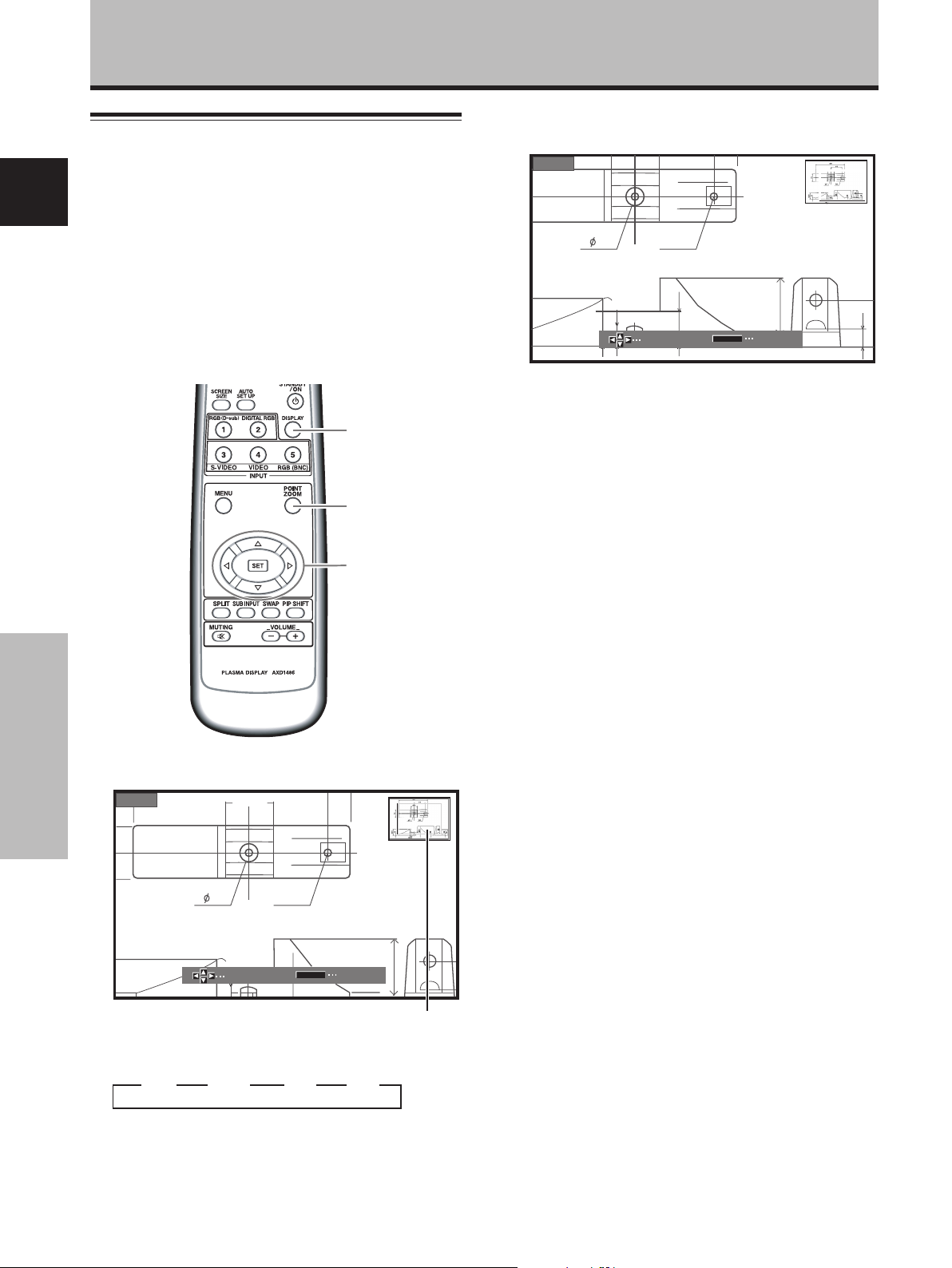
Enlarging one part of the screen
(POINT ZOOM)
English
This plasma display allows enlarging of the screen image
by ratios of [x 1.5], [x 2], and [x 3]. When enlarging the
screen, the 5/∞/2/3 buttons can be used to move the
enlarged viewing area around the screen.
¶ The range of zoom possible can be confirmed by viewing
the Zoom-Navi subscreen at the upper right of the main
screen. The Zoom-Navi subscreen is displayed for about
three seconds whenever the POINT ZOOM button, one
of the 5/∞/2/3 buttons, or DISPLAY button is pressed.
DISPLAY
POINT
ZOOM
5/∞/2/3
2 Using the 5/∞/2/3 buttons, move the screen to
the desired part of the image.
x 1.5
SCROLL
R12
22.1
P.ZOOM
10
ZOOM
24
10
84.3
÷ Pressing the POINT ZOOM and 5/∞/2/3 buttons
again will change the zoom ratio and the position of
screen enlarged.
÷ If the input signal changes, or if the menu screen is
displayed and the input is changed, or if the
multiscreen mode is selected, the POINT ZOOM
function will be canceled.
Note
Be aware that when the display is used for commercial or public
viewing purposes, selecting the [WIDE], [ZOOM], [CINEMA] or
[FULL] mode settings may violate the rights of authors protected
under copyright law.
1 Press the remote control unit’s POINT ZOOM
Operation
button.
x 1.5
24
66.0
SCROLL
10
R12
22.1
P.ZOOM
ZOOM
Zoom-Navi subscreen
Each time the POINT ZOOM button is pressed, the
zoom ratio alternates in the following order:
3 OFF 3 x 1.5 3 x 2 3 x 3
Note
During use of the POINT ZOOM function, the screen size cannot
be changed.
24
En
Page 28
Multiscreen display
The plasma display’s multiscreen function allows the
simultaneous display of two inputs. The multiscreen
display include three modes, 2-SCREEN, PinP, and PoutP.
DISPLAY
SPLIT
PIP SHIFT
Operation
3 PoutP
The subscreen is displayed outside the right side of
the main screen.
66.0
R12
24
22.1
10
2 Press the remote control unit’s SUB INPUT button
to select the subscreen input source.
English
SUB INPUT
SWAP
1 Press the remote control unit’s SPLIT button.
Each time the button is pressed the multiscreen
display changes in the following order:
3 2-SCREEN 3 PinP 3 PoutP 3 OFF
1 2-SCREEN
The main screen is displayed on the left and the
subscreen on the right.
66.0
R12
24
22.1
10
2 PinP
The subscreen is displayed in one of the four corners
of the main screen.
66.0
R12
24
22.1
10
To exchange the main screen and subscreen
inputs
Press the remote control unit’s SWAP button.
¶ When 2-SCREEN mode has been selected:
The right and left sides of the display will switch; what
was previously the main screen will now show the
subscreen, and vice versa.
¶ When PinP or PoutP has been selected:
What was previously the main screen image will now
appear in reduced size as the subscreen image, and
vice versa.
To change the position of the subscreen in PinP
mode:
Press the remote control unit’s PIP SHIFT.
Each time the button is pressed, the position of the
subscreen moves in the following order:
3 Lower right 3 Upper right
Lower left 2 Upper left 2
To display the currently selected input
Press the DISPLAY button.
If the DISPLAY button is pressed while in multiscreen
mode, the main screen and sub-screen will each be
displayed with its currently selected input.
Notes
¶ When using the plasma display in a profit-making activity, or
when exhibiting images publicly, using the screen size function
to compress or stretch the image may result in infringement of
the copyrights of the image owners.
¶ If the multiscreen display is left on for an extended period of
time, or if the same multiscreen display is repeatedly shown
for short periods on an everyday basis, a residual image
pattern may be burned onto the screen.
¶ When selecting the 2-SCREEN mode, the screen image may
appear somewhat rougher, depending on the source used.
¶ The multiscreen mode will be canceled if a menu is opened, or
if POINT ZOOM is performed.
¶ The screen size cannot be changed during multiscreen display.
¶ The sound of the input selected in the main screen is
outputted when using the multiscreen function.
25
Operation
En
Page 29
Operation
Automatic power-off
(POWER MANAGEMENT)
The plasma display is equipped with [POWER
English
MANAGEMENT] and [AUTO POWER OFF] functions;
when set, the function automatically switches the unit to
either standby mode or power off mode whenever a sync
signal is not detected (a warning message is displayed on
the screen before the functions operate).
Notes
÷ [POWER MANAGEMENT] settings are supported only when a
computer signal is input to INPUT 1 or INPUT 5 (PDA-5003
only), or when INPUT2 is selected.
÷ The auto-power-off function can be used only in those cases
other than the inputs used in the preceding item.
÷ Always turn off the plasma display’s main power switch when
not using the display for extended periods of time.
[In all other cases]
MENU INPUT3
PICTURE SCREEN SETUP OPTION
MENU
:
:
MIDDLE
:
MIDDLE
:
LOW
:
ON
:
OFF
:
AUTO
AUTO POWER OFF DISABLE
COLOR TEMP.
DNR
MPEG NR
CTI
PURECINEMA
COLOR SYSTEM
SET
CHANGE EXIT
3 Press the SET button to confirm selection of the
[POWER MANAGEMENT] or [AUTO POWER OFF].
The factory default setting is [OFF/DISABLE].
Each time the button is pressed, the setting alternates
as follows:
3 OFF/DISABLE
ON/ENABLE 2
INPUT
MENU
2/3
SET
Display operating
panel
Remote control unit
Operation
1 Press the MENU button to display the menu screen.
MENU INPUT1
PICTURE SCREEN SETUP OPTION
CONTRAST
BRIGHTNESS
R.LEVEL
G.LEVEL
B.LEVEL
H.ENHANCE
V.ENHANCE
PICTURE RESET
:
0
:
0
:
0
:
0
:
0
:
0
:
0
2 Use the 2/3 buttons to select [SETUP].
[When computer signal is input to INPUT1 or
INPUT5 (PDA-5003 only), or when INPUT2 is used]
MENU INPUT1
PICTURE SCREEN SETUP OPTION
POWER MANAGEMENT
CLAMP POSITION
SIGNAL FORMAT
:
OFF
:
AUTO
:
:
V
GA
INPUT
MENU
2/3
SET
÷ OFF/DISABLE.....
The display will continue in operating mode,
regardless of the presence/absence of an input sync
signal.
÷ POWER MANAGEMENT: ON.....
If a sync signal is not detected, a warning message is
first displayed for 8 seconds, after which the display
automatically enters the standby mode, and the ON
indicator flashes green. If a sync signal (*1) is input
again later, the plasma display automatically returns to
normal operating mode.
*1 Except when input signal is G ON SYNC or composite
SYNC.
÷ AUTO POWER OFF: ENABLE.....
If no sync signal is detected for 8 minutes or more, a
warning message will be displayed for 30 seconds,
after which the display’s power will switch to power off
mode.
4 When the setup is finished, press the MENU
button to exit the menu screen.
Note
The [POWER MANAGEMENT] and [AUTO POWER OFF]
functions must be set individually for each input (INPUT1 to
INPUT5).
To return to operating mode:
÷ To return to normal operation from the [POWER
MANAGEMENT] function’s standby mode, either operate
your computer, or press the INPUT button on the plasma
display or remote control unit.
÷ To return to normal operation from the [AUTO POWER
OFF] function’s power off condition, press the STANDBY/
ON button on the plasma display or on the remote control
unit.
26
En
Page 30
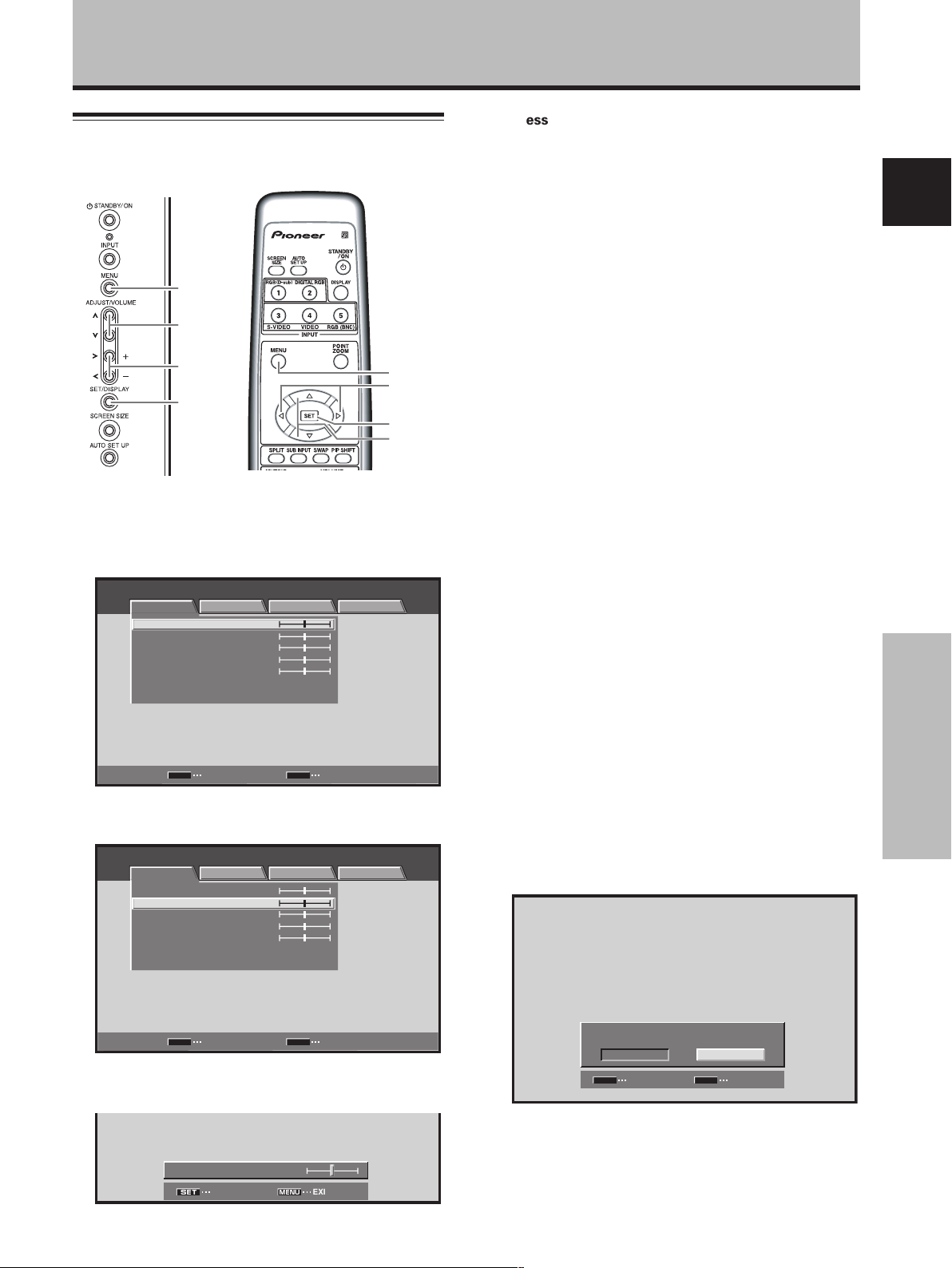
PICTURE/SCREEN Adjustment
PICTURE adjustment
4 Press the SET button.
Pressing the SET button writes the value into the
memory and returns the display to the step 2 screen.
MENU
5/∞
Display operating
2/3
SET
Remote control unit
MENU
2/3
SET
5/∞
panel
1 Press the MENU button to display the menu
screen.
MENU INPUT1
PICTURE SCREEN SETUP OPTION
ENTER
:
0
:
0
:
0
:
0
:
0
MENU
EXIT
CONTRAST
BRIGHTNESS
COLOR
TINT
SHARPNESS
PICTURE RESET
SET
2 Use the 5/∞ buttons to select the adjustment
item, then press the SET button.
MENU INPUT1
PICTURE
CONTRAST
BRIGHTNESS
COLOR
TINT
SHARPNESS
PICTURE RESET
SCREEN SETUP OPTION
:
0
:
0
:
0
:
0
:
0
5 When the setup is finished, press the MENU
button to exit the menu screen.
Note
Make these adjustments for each input (INPUT1 to INPUT5) and
signals.
[PICTURE] mode adjustment items
Below are brief descriptions of the options that can be set
in the [PICTURE] mode.
CONTRAST ············· Adjust according to the surrounding
brightness so that the picture can be
seen clearly.
BRIGHTNESS ·········· Adjust so that the dark parts of the
picture can be seen clearly.
COLOR ···················· Adjust to the desired depth (Setting
to a slightly deep color will create a
natural looking picture).
TINT························· Adjust so that flesh tones look
normal.
SHARPNESS ··········· Normally set to the center position.
To create a softer picture, set to the
left of center. To create a sharper
picture, set to the right of center.
Note
Consult the Operating Instructions for your Plasma Display
regarding PICTURE adjustment when inputting computer signals.
To reset [PICTURE] mode settings to the default
If settings have been adjusted excessively or the picture
on the screen no longer appears natural, it may prove
more beneficial to reset the [PICTURE] mode to default
settings instead of trying to make adjustments under
already adjusted conditions.
1 In step 2 in the previous procedure, use the 5/∞
buttons to select [PICTURE RESET], then press the
SET button.
English
PICTURE/SCREEN Adjustment
SET
ENTER EXIT
MENU
3 Use the 2/3 buttons to adjust the picture quality
as desired.
:
MENU
0
EXIT
BRIGHTNESS
SET
SET
PICTURE RESET
MENU
NO
EXIT
YES
SET
SET
2 Use the 2/3 buttons to select [YES], and press
the SET button.
All [PICTURE] mode settings are returned to the
factory set default.
27
En
Page 31

PICTURE/SCREEN Adjustment
Adjusting screen POSITION, CLOCK,
and PHASE <automatic adjust>
English
By pressing the AUTO SET UP button on either remote
control unit or the plasma display’s operating panel (or by
selecting [AUTO SET UP MODE] from the menu), the unit
will automatically set the screen position and clock to
best match the current image input.
When the automatic setup mode is
selected, the unit will automatically be
adjusted to the optimum image settings
whenever the power is turned on, the input
source is changed, or the type of input
signal is changed.
When the button is pressed, the optimum
settings are automatically selected for the
current input source.
Remote control unit
AUTO SET UP
Display operating
Panel
Press the AUTO SET UP button on either the display
or remote control unit.
PICTURE/SCREEN Adjustment
AUTO SET UP
AUTO
SET UP
MENU
5/∞
2/3
SET
Display operating
panel
Remote control unit
1 Press the MENU button to display the menu
screen.
MENU INPUT1
PICTURE SCREEN SETUP OPTION
ENTER
:
0
:
0
:
0
:
0
:
0
MENU
EXIT
CONTRAST
BRIGHTNESS
COLOR
TINT
SHARPNESS
PICTURE RESET
SET
2 Use the 2/3 buttons to select [OPTION].
MENU INPUT1
PICTURE SCREEN SETUP OPTION
LANGUAGE ENGLISH
ENERGY SAVE
SCREEN MGT.
ORBITER OFF
MASK CONTROL ON
AUTO SET UP MODE INACTIVE
AUTO FUNCTION OFF
AUDIO OUT FIXED
:
:
STANDARD
:
OFF
:
:
:
:
:
MENU
2/3
SET
5/∞
Notes
÷ This setting is supported only when a computer signal is
connected to INPUT1 or INPUT5.
÷ Perform this adjustment individually for each input function
(INPUT1 or INPUT5), and each signal type.
÷ Optimum settings may not be possible for low-luminance and
certain other signals. In such cases, use the adjustment
methods explained on the next page, “Adjusting screen
POSITION, CLOCK, and PHASE <manual adjust>“.
28
En
SET
ENTER
MENU
EXIT
Page 32

PICTURE/SCREEN Adjustment
3 Use the 5/∞ buttons to select [AUTO SET UP
MODE].
MENU INPUT1
PICTURE SCREEN SETUP OPTION
MENU
:
:
STANDARD
:
OFF
:
:
:
:
:
LANGUAGE ENGLISH
ENERGY SAVE
SCREEN MGT.
ORBITER OFF
MASK CONTROL ON
AUTO SET UP MODE INACTIVE
AUTO FUNCTION OFF
AUDIO OUT FIXED
SET
CHANGE EXIT
4 Press the SET button to activate the setting.
The factory default setting is [INACTIVE].
Each time the button is pressed, the setting alternates
as follows:
3 INACTIVE
ACTIVE 2
5 When finished with the setting, press the MENU
button to return to the normal screen image.
Notes
÷ This setting is supported only when a computer signal is
connected to INPUT1 or INPUT5.
÷ Optimum settings may not be possible for low-luminance and
certain other signals. In such cases, set the [AUTO SETUP
MODE] to [INACTIVE], and use the manual adjustment
methods explained in the following section, “Adjusting
screen POSITION, CLOCK, and PHASE <manual adjust>“.
Adjusting screen POSITION, CLOCK,
and PHASE
This setting can be adjusted when a computer signal is
connected to INPUT1, INPUT2, or INPUT5.
<manual adjust>
1 Press the MENU button to display the menu
screen.
MENU INPUT1
PICTURE SCREEN SETUP OPTION
ENTER
:
0
:
0
:
0
:
0
:
0
MENU
EXIT
CONTRAST
BRIGHTNESS
COLOR
TINT
SHARPNESS
PICTURE RESET
SET
2 Use the 2/3 buttons to select [SCREEN].
MENU INPUT1
PICTURE SCREEN SETUP OPTION
POSITION
CLOCK
PHASE
SCREEN RESET
SET
ENTER EXIT
INPUT2, 3 or 4 is selected, the following screen will
appear and the [POSITION] adjustment only can be
selected.
MENU INPUT2
PICTURE SCREEN SETUP OPTION
POSITION
SCREEN RESET
:
:
:
:
00
00
/
0
0
MENU
/
English
PICTURE/SCREEN Adjustment
Display operating
panel
MENU
5/∞
2/3
SET
Remote control unit
MENU
2/3
SET
5/∞
SET
ENTER EXIT
MENU
3 Use the 5/∞ buttons to select the adjustment
item, then press the SET button.
MENU INPUT1
PICTURE SCREEN SETUP OPTION
POSITION
CLOCK
PHASE
SCREEN RESET
SET
ENTER EXIT
:
00
:
0
:
0
MENU
/
29
En
Page 33

PICTURE/SCREEN Adjustment
4 Use the 2/3 and 5/∞ buttons to select the
desired value.
÷ When the [POSITION] item is selected, the 2/3
buttons control movement in the Horizontal
English
direction (H), and the 5/∞ buttons control
movement in the Vertical direction (V).
POSITION
H V
00
SET
SET
MENU
EXIT
÷ Use the 2/3 buttons for the adjustments of
[CLOCK] and [PHASE].
CLOCK
SET
SET
:
0
MENU
EXIT
5 Press the SET button.
Pressing the SET button writes the value into the
memory and returns the display to the step 3 screen.
6 When adjustment is finished, press the MENU
button to exit the menu screen.
Notes
PICTURE/SCREEN Adjustment
÷ Make these adjustments for each input (INPUT1 or INPUT5)
and signals.
÷ If INPUT2 is selected, only the [POSITION] can be adjusted.
[SCREEN] mode adjustment items
Below are brief descriptions of the options that can be set
in the [SCREEN] mode.
POSITION
H ··························· Adjust the picture’s position to the
left or right.
V ···························· Adjust the picture’s position upward
or downward.
CLOCK ···················· Adjust letter breakup or noise on the
screen. This setting adjusts the
display’s internal clock signal
frequency that corresponds to the
input video signal.
PHASE····················· Adjust so that there is minimum
flicker of screen letters or color
misalignment. This setting adjusts
the phase of the internal clock signal
adjusted by the [CLOCK] setting.
Notes
÷ The [CLOCK] and [PHASE] adjustment items are supported
only for INPUT1 and INPUT5.
÷ When the [CLOCK] frequency is changed, the [POSITION]
command’s horizontal [H] option may require readjustment.
÷ If the adjustment items in the [SCREEN] mode are adjusted
excessively, the picture may not be displayed properly.
÷ When the [AUTO SET UP MODE] set to [ACTIVE], selecting the
[POSITION] and [CLOCK] adjust modes will cause a message
to be displayed on the screen, but adjustment is possible.
However, if the input source is changed, the adjustment value
stored in memory will be the one automatically set with the
auto setup mode. If you wish to record a manually set
adjustment value, set the [AUTO SET UP MODE] to
[INACTIVE] (page 28) before beginning your adjustments.
To reset [SCREEN] mode settings to the default
If settings have been adjusted excessively or the picture
on the screen no longer appears natural, it may prove
more beneficial to reset the [SCREEN] mode to default
settings instead of trying to make adjustments under
already adjusted conditions.
1 In step 3 in the previous procedure, use the 5/∞
buttons to select [SCREEN RESET], then press the
SET button.
30
En
SCREEN RESET
MENU
NO
EXIT
YES
SET
SET
2 Use the 2/3 buttons to select [YES], and press
the SET button.
All [SCREEN] mode settings are returned to the
factory set default.
Page 34

Other Operations
Setting the orbiter (ORBITER)
At set time intervals (about once every 8 minutes), this
function automatically changes the screen display position
by incremental amounts. The amount of screen movement
is 1 pixel horizontally or vertically.
When displaying a still image, setting [ORBITER] to [ON]
helps prevent the screen from being burnt with a lag image.
÷ This function is not supported when using the POINT
ZOOM function, multiscreen function, or menu display.
MENU
5/∞
4 Press the SET button to activate the setting.
The factory default setting is [OFF].
Each time the button is pressed, the setting alternates
as follows:
3 OFF
ON 2
5 When finished with the setting, press the MENU
button to return to the normal screen image.
Note
The [ORBITER] setting affects all input sources.
Side mask position (MASK CONTROL)
When screen size is set to [DOT BY DOT] or [4:3], or when
using multiscreen display, the position of the black stripes
on the side of the screen and the position of the subscreen
are changed slightly each time the power is turned on, in
order to alleviate burning of lag images on the screen.
English
2/3
SET
Display operating panel Remote control unit
1 Press the MENU button to display the menu
screen.
MENU INPUT1
PICTURE SCREEN SETUP OPTION
CONTRAST
BRIGHTNESS
COLOR
TINT
SHARPNESS
PICTURE RESET
:
0
:
0
:
0
:
0
:
0
2 Use the 2/3 buttons to select [OPTION].
MENU INPUT1
PICTURE SCREEN SETUP
LANGUAGE ENGLISH
ENERGY SAVE
SCREEN MGT.
ORBITER OFF
MASK CONTROL ON
AUTO SET UP MODE INACTIVE
AUTO FUNCTION OFF
AUDIO OUT FIXED
OPTION
:
:
STANDARD
:
OFF
:
:
:
:
:
3 Use the 5/∞ buttons to select [ORBITER].
MENU INPUT1
PICTURE SCREEN SETUP OPTION
LANGUAGE ENGLISH
ENERGY SAVE
SCREEN MGT.
ORBITER OFF
MASK CONTROL ON
AUTO SET UP MODE INACTIVE
AUTO FUNCTION OFF
AUDIO OUT FIXED
:
:
STANDARD
:
OFF
:
:
:
:
:
MENU
2/3
SET
5/∞
MENU
5/∞
2/3
SET
Display operating panel
1
Press the MENU button to display the menu screen.
MENU INPUT1
PICTURE SCREEN SETUP OPTION
CONTRAST
BRIGHTNESS
COLOR
TINT
SHARPNESS
PICTURE RESET
Remote control unit
:
0
:
0
:
0
:
0
:
0
2 Use the 2/3 buttons to select [OPTION].
MENU INPUT1
PICTURE SCREEN SETUP
LANGUAGE ENGLISH
ENERGY SAVE
SCREEN MGT.
ORBITER OFF
MASK CONTROL ON
AUTO SET UP MODE INACTIVE
AUTO FUNCTION OFF
AUDIO OUT FIXED
OPTION
:
:
STANDARD
:
OFF
:
:
:
:
:
MENU
2/3
SET
5/∞
Other Operations
31
En
Page 35

Other Operations
3 Use the 5/∞ buttons to select [MASK CONTROL].
MENU INPUT1
PICTURE SCREEN SETUP OPTION
:
:
STANDARD
:
OFF
:
:
:
:
:
English
LANGUAGE ENGLISH
ENERGY SAVE
SCREEN MGT.
ORBITER OFF
MASK CONTROL ON
AUTO SET UP MODE INACTIVE
AUTO FUNCTION OFF
AUDIO OUT FIXED
4 Press the SET button to activate the setting.
The factory default setting is [ON].
Each time the button is pressed, the setting alternates
as follows:
3 OFF
ON 2
5 When finished with the setting, press the MENU
button to return to the normal screen image.
Note
The [MASK CONTROL] setting affects all input sources.
Screen management settings
(SCREEN MGT.)
In order to alleviate burning of lag images in the screen,
this plasma display is equipped with a screen
management program that allows automatic switching of
the display image at regular intervals. The program can be
set to determine how the 24-hour screen management
cycle is repeated.
For information about detailed screen management
settings, consult your professional installation technician.
Other Operations
1 Press the MENU button to display the menu
screen.
MENU INPUT1
PICTURE SCREEN SETUP OPTION
CONTRAST
BRIGHTNESS
COLOR
TINT
SHARPNESS
PICTURE RESET
:
0
:
0
:
0
:
0
:
0
2 Use the 2/3 buttons to select [OPTION].
MENU INPUT1
PICTURE SCREEN SETUP
LANGUAGE ENGLISH
ENERGY SAVE
SCREEN MGT.
ORBITER OFF
MASK CONTROL ON
AUTO SET UP MODE INACTIVE
AUTO FUNCTION OFF
AUDIO OUT FIXED
OPTION
:
:
STANDARD
:
OFF
:
:
:
:
:
3 Use the 5/∞ buttons to select [SCREEN MGT.],
then press the SET button.
MENU INPUT1
PICTURE SCREEN SETUP OPTION
LANGUAGE ENGLISH
ENERGY SAVE
SCREEN MGT.
ORBITER OFF
MASK CONTROL ON
AUTO SET UP MODE INACTIVE
AUTO FUNCTION OFF
AUDIO OUT FIXED
:
:
STANDARD
:
OFF
:
:
:
:
:
4 Use the 5/∞ buttons to select [STATUS].
SCREEN MGT.
STATUS
TIME TO ACTIVATE
START
SET
RETURN
:
OFF
:
01H00M
MENU
EXIT
32
En
MENU
5/∞
2/3
SET
Display
operating
panel
Remote control unit
MENU
2/3
SET
5/∞
5 Use the 2/3 buttons to select [ONCE] or
[REPEAT].
The factory default setting is [OFF].
Each time the button is pressed, the setting alternates
as follows:
÷ ONCE ....... The screen management program is
÷ REPEAT .... The screen management program is
÷ OFF .......... Screen management program is
3 OFF 2
3 ONCE 2
3 REPEAT 2
performed once only.
performed repeatedly (24-hour cycle).
disabled, and normal screen image is
displayed continuously.
Page 36

Other Operations
Under factory default settings, the screen display
contents will change as follows:
Set
[ONCE]
[TIME TO
ACTIVATE]
(set in step 7).
Set
[REPEAT]
[TIME TO
ACTIVATE]
(set in step 7).
Inverse
image*
10 minutes 30 minutes
Inverse
image*
10 minutes 30 minutes 10 minutes
* The color and brightness of the current image are displayed in
inverse values. The respective RGB color output levels are
inverted, with light areas appearing dark, and dark areas
appearing light.
White mask
display
White mask
display
24 hours
This cycle repeats
Power standby mode
Screen management
function ends here
Power
standby
mode
Inverse
image*
Notes
÷ When set to [ONCE], after the screen management program
ends, this part of the display will change to the [OFF]
message. If you wish to continue the screen management
program, use the 2/3 buttons to select [ONCE] again, or
change to [REPEAT].
÷ During screen management operation when set to [ONCE] or
[REPEAT], if the display’s MAIN POWER switch is turned OFF,
the screen management program will end, and this part of the
display will change to display the message [OFF]. If you wish
to continue the screen management program, use the 2/3
buttons to select [ONCE] or [REPEAT] again.
6 Use the 5/∞ buttons to select [TIME TO ACTIVATE].
SCREEN MGT.
:
REPEATSTATUS
:
TIME TO ACTIVATE
START
SET
RETURN EXIT
01H00M
MENU
7 Use the 2/3 buttons to set the time you wish the
screen management program to begin.
When the 2/3 buttons are pressed, the screen
management operation can be set from 0 to 24 hours,
in 10-minute units.
8 Use the 5/∞ buttons to select [START].
SCREEN MGT.
:
REPEATSTATUS
:
TIME TO ACTIVATE
START
SET
SET EXIT
00H10M
MENU
9 Press the SET button.
The set value will be stored in memory, and the screen
will return to that shown in step 2.
The timer begins when the SET button is pressed, and
after passage of the time set in step 7, the screen
management program will begin operating.
10 When finished with the setting, press the MENU
button to return to the normal screen image.
Note
The [SCREEN MGT.] setting affects all input sources.
Energy saving settings
(ENERGY SAVE)
The power control function allows screen brightness to
be suppressed as a means of lowering power
consumption and reducing display deterioration.
MENU
5/∞
2/3
SET
Display operating panel Remote control unit
1 Press the MENU button to display the menu
screen.
MENU INPUT1
PICTURE SCREEN SETUP OPTION
CONTRAST
BRIGHTNESS
R.LEVEL
G.LEVEL
B.LEVEL
H.ENHANCE
V.ENHANCE
PICTURE RESET
:
0
:
0
:
0
:
0
:
0
:
0
:
0
2 Use the 2/3 buttons to select [OPTION].
MENU INPUT1
PICTURE SCREEN SETUP
LANGUAGE ENGLISH
ENERGY SAVE
SCREEN MGT.
ORBITER OFF
MASK CONTROL ON
AUTO SET UP MODE INACTIVE
AUTO FUNCTION OFF
AUDIO OUT FIXED
OPTION
:
:
STANDARD
:
OFF
:
:
:
:
:
MENU
2/3
SET
5/∞
English
Other Operations
33
En
Page 37

Other Operations
3 Press the 5/∞ buttons to select [ENERGY SAVE].
MENU INPUT1
PICTURE SCREEN SETUP OPTION
:
:
STANDARD
:
OFF
:
:
:
:
:
English
LANGUAGE ENGLISH
ENERGY SAVE
SCREEN MGT.
ORBITER OFF
MASK CONTROL ON
AUTO SET UP MODE INACTIVE
AUTO FUNCTION OFF
AUDIO OUT FIXED
Changing the color temperature
(COLOR TEMP.)
MENU
SET
CHANGE EXIT
MENU
4 Press the SET button to select [ENERGY SAVE]
setting.
The factory default setting is [STANDARD].
Each time the SET button is pressed, the setting
changes as follows:
3 AUTO
MODE3 2
MODE2 2
3 STANDARD
MODE1 2
÷ STANDARD ... Brightness is controlled in
accordance with input signal to
produce bright, easily viewed image.
÷ MODE1 ......... Brightness is controlled in
accordance with input signal, but
power consumption is less than that
used in [STANDARD] mode.
÷ MODE2 ......... Brightness is controlled in accordance
with input signal, but power
consumption is less than that used in
[MODE1].
÷ MODE3 ......... Brightness is set at fixed level,
regardless of input signal level.
Effective at reducing screen aging
Other Operations
due to burned lag images, etc.
÷ AUTO ............ Brightness is set automatically in
response to ambient lighting
conditions so as to produce optimum
image appearance.
5 When finished with the setting, press the MENU
button to return to the normal screen image.
Note
The [ENERGY SAVE] setting affects all input sources.
5/∞
2/3
SET
Display operating panel
Remote control unit
1 Press the MENU button to display the menu
screen.
MENU INPUT1
PICTURE SCREEN SETUP OPTION
ENTER
:
0
:
0
:
0
:
0
:
0
MENU
EXIT
CONTRAST
BRIGHTNESS
COLOR
TINT
SHARPNESS
PICTURE RESET
SET
2 Use the 2/3 buttons to select [SETUP].
MENU INPUT1
PICTURE SCREEN SETUP OPTION
AUTO POWER OFF DISABLE
COLOR TEMP.
DNR
MPEG NR LOW
CTI ON
PURECINEMA
COLOR DECODING
CLAMP POSITION
SIGNAL FORMAT
:
:
MIDDLE
:
:
MIDDLE
:
:
:
OFF
:
RGB
:
AUTO
:
:
VGA
MENU
2/3
SET
5/∞
34
En
SET
CHANGE EXIT
MENU
Page 38

3 Use the 5/∞ buttons to select [COLOR TEMP.],
then press the SET button.
MENU INPUT1
PICTURE SCREEN SETUP OPTION
AUTO POWER OFF
COLOR TEMP. MIDDLE
DNR
MPEG NR LOW
CTI ON
PURECINEMA
COLOR DECODING
CLAMP POSITION
SIGNAL FORMAT
:
DISABLE
:
:
:
MIDDLE
:
:
:
OFF
:
RGB
:
AUTO
:
:
VGA
Other Operations
Reducing video noise (DNR)
Make this setting if video noise is objectionable.
English
MENU
SET
ENTER EXIT
MENU
4 Use the 2/3 buttons to select the desired color
temperature setting.
COLOR TEMP.
SET
SET
:
MIDDLE
MENU
EXIT
The factory default setting is [MIDDLE]. Each time the
button is pressed, the color temperature setting
changes as shown:
3 MIDDLE 2
3 MID LOW 2 3 LOW 2
3 MID HIGH 2 3 HIGH 2
5 Press the SET buttton.
The [COLOR TEMP.] function is set and the screen
returns to that shown in step 4.
6 When finished with the setting, press the MENU
button to return to the normal screen image.
Note
[COLOR TEMP.] settings are supported only for input signal from
a video component. Make settings individually for each input
(INPUT1, INPUT3 to INPUT5), and for each signal type.
5/∞
2/3
SET
Display operating panel
Remote control unit
MENU
2/3
SET
5/∞
1 Press the MENU button to display the menu screen.
MENU INPUT1
PICTURE SCREEN SETUP OPTION
CONTRAST
BRIGHTNESS
COLOR
TINT
SHARPNESS
PICTURE RESET
:
0
:
0
:
0
:
0
:
0
2 Use the 2/3 buttons to select [SETUP].
MENU INPUT1
PICTURE SCREEN SETUP OPTION
MENU
:
:
MIDDLE
:
:
MIDDLE
:
:
:
OFF
:
RGB
:
AUTO
:
:
VGA
AUTO POWER OFF DISABLE
COLOR TEMP.
DNR
MPEG NR LOW
CTI ON
PURECINEMA
COLOR DECODING
CLAMP POSITION
SIGNAL FORMAT
SET
CHANGE EXIT
3 Use the 5/∞ buttons to select [DNR], then press
the SET button.
MENU INPUT1
PICTURE SCREEN SETUP OPTION
AUTO POWER OFF DISABLE
COLOR TEMP.
DNR MIDDLE
MPEG NR LOW
CTI ON
PURECINEMA
COLOR DECODING
CLAMP POSITION
SIGNAL FORMAT
:
:
MIDDLE
:
:
:
:
:
OFF
:
RGB
:
AUTO
:
:
VGA
Other Operations
35
En
Page 39

Other Operations
4 Use the 2/3 buttons to select the desired [DNR]
setting.
:
MIDDLE
MENU
EXIT
English
DNR
SET
SET
The factory default setting is [MIDDLE]. Each time the
button is pressed, the digital noise reduction setting
changes as shown:
3 OFF 2
3 HIGH 2 3 MIDDLE 2 3 LOW 2
÷ The noise reduction effect increases in order LOW
= MIDDLE = HIGH
5 Press the SET buttton.
The [DNR] function is set and the screen returns to
that shown in step 4.
6 When finished with the setting, press the MENU
button to return to the normal screen image.
Note
[DNR] settings are supported only for input signal from a video
component. Make settings individually for each input (INPUT1,
INPUT3 to INPUT5), and for each signal type.
Reducing noise in MPEG images
(MPEG NR)
Set this function if digital broadcasts, DVD and other
MPEG images are distorted with so-called “mosquito
noise”.
Other Operations
1 Press the MENU button to display the menu screen.
MENU INPUT3
PICTURE
CONTRAST
BRIGHTNESS
COLOR
TINT
SHARPNESS
PICTURE RESET
SCREEN SETUP OPTION
:
0
:
0
:
0
:
0
:
0
SET
ENTER
MENU
EXIT
2 Use the 2/3 buttons to select [SETUP].
MENU INPUT3
PICTURE SCREEN SETUP OPTION
MENU
:
:
MIDDLE
:
MIDDLE
:
LOW
:
ON
:
OFF
:
AUTO
AUTO POWER OFF DISABLE
COLOR TEMP.
DNR
MPEG NR
CTI
PURECINEMA
COLOR SYSTEM
SET
CHANGE EXIT
3 Use the 5/∞ buttons to select [MPEG NR], then
press the SET button.
MENU INPUT3
PICTURE SCREEN SETUP OPTION
AUTO POWER OFF DISABLE
COLOR TEMP.
DNR
MPEG NR
CTI ON
PURECINEMA
COLOR SYSTEM
:
:
MIDDLE
:
MIDDLE
:
LOW
:
:
OFF
:
AUTO
4 Use the 2/3 buttons to select the desired [MPEG
NR] setting.
MENU
5/∞
2/3
SET
Display operating panel Remote control unit
36
En
MENU
2/3
SET
5/∞
MPEG NR
SET
SET
:
LOW
MENU
EXIT
The factory default setting is [LOW]. Each time the button
is pressed, the noise reduction setting changes as shown:
3 OFF 2
3 HIGH 2 3 MIDDLE 2 3 LOW 2
÷ The noise reduction effect increases in order LOW
= MIDDLE = HIGH
5 Press the SET button.
The [MPEG NR] function is set and the screen returns
to that shown in step 4.
6 When finished with the setting, press the MENU
button to return to the normal screen image.
Note
[MPEG NR] settings are supported only for input signal from a
video component. Make settings individually for each input
(INPUT1, INPUT3 to INPUT5), and for each signal type.
Page 40

Increasing color border contrast
(CTI)
Enhance color contour contrast as desired.
Other Operations
3 Use the 5/∞ buttons to select [CTI], then press
the SET button.
MENU INPUT3
PICTURE SCREEN SETUP OPTION
AUTO POWER OFF DISABLE
COLOR TEMP.
DNR
MPEG NR
CTI ON
PURECINEMA
COLOR SYSTEM
:
:
MIDDLE
:
MIDDLE
:
LOW
:
:
OFF
:
AUTO
English
MENU
5/∞
2/3
SET
Display operating panel
Remote control unit
1 Press the MENU button to display the menu
screen.
MENU INPUT3
PICTURE
CONTRAST
BRIGHTNESS
COLOR
TINT
SHARPNESS
PICTURE RESET
SCREEN SETUP OPTION
:
0
:
0
:
0
:
0
:
0
SET
ENTER
MENU
EXIT
2 Use the 2/3 buttons to select [SETUP].
MENU INPUT3
PICTURE SCREEN SETUP OPTION
AUTO POWER OFF DISABLE
COLOR TEMP.
DNR
MPEG NR
CTI
PURECINEMA
COLOR SYSTEM
:
:
MIDDLE
:
MIDDLE
:
LOW
:
ON
:
OFF
:
AUTO
MENU
2/3
SET
5/∞
SET
ENTER EXIT
MENU
4 Use the 2/3 buttons to select the desired [CTI]
setting.
CTI
SET
SET
:
ON
MENU
EXIT
The factory default setting is [ON]. Each time the
button is pressed, the setting changes as shown:
3 OFF 2
3 ON 2
5 Press the SET button.
The [CTI] function is set and the screen returns to that
shown in step 4.
6 When finished with the setting, press the MENU
button to return to the normal screen image.
Note
[CTI] settings are supported only for input signal from a video
component. Make settings individually for each input (INPUT1,
INPUT3 to INPUT5), and for each signal type.
Other Operations
SET
CHANGE EXIT
MENU
37
En
Page 41
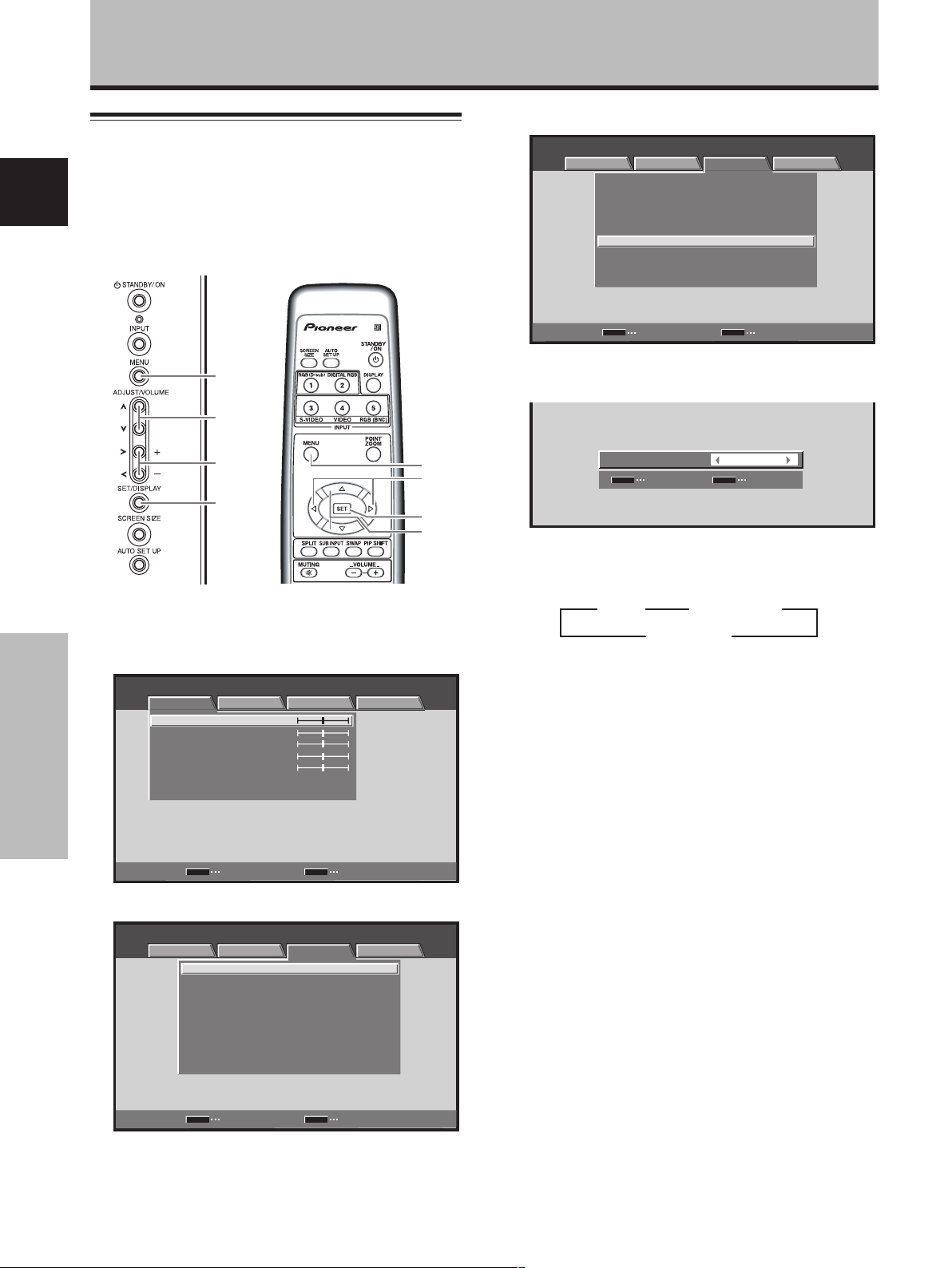
Other Operations
Setting the PURECINEMA mode
Allows even higher fidelity DVD playback of film recordings and
other images.
English
Note
Make settings individually for each input (INPUT1, INPUT3 to
INPUT5), and for each signal type.
3 Use the 5/∞ buttons to select [PURECINEMA].
MENU INPUT1
PICTURE SCREEN SETUP OPTION
AUTO POWER OFF
COLOR TEMP.
DNR
MPEG NR LOW
CTI ON
PURECINEMA
COLOR DECODING
CLAMP POSITION
SIGNAL FORMAT
:
DISABLE
:
MIDDLE
:
:
MIDDLE
:
:
:
OFF
:
RGB
:
AUTO
:
:
VGA
MENU
5/∞
2/3
SET
Display operating panel
Remote control unit
1 Press the MENU button to display the menu
screen.
MENU INPUT1
PICTURE SCREEN SETUP OPTION
ENTER
:
0
:
0
:
0
:
0
:
0
MENU
Other Operations
CONTRAST
BRIGHTNESS
COLOR
TINT
SHARPNESS
PICTURE RESET
SET
2 Use the 2/3 buttons to select [SETUP].
MENU INPUT1
PICTURE SCREEN SETUP OPTION
MENU
:
:
MIDDLE
:
:
MIDDLE
:
:
:
OFF
:
RGB
:
AUTO
:
:
VGA
AUTO POWER OFF DISABLE
COLOR TEMP.
DNR
MPEG NR LOW
CTI ON
PURECINEMA
COLOR DECODING
CLAMP POSITION
SIGNAL FORMAT
SET
CHANGE EXIT
EXIT
MENU
2/3
SET
5/∞
SET
ENTER EXIT
MENU
4 Use the 2/3 buttons to select the desired
[PURECINEMA] mode.
PURECINEMA
SET
SET
:
OFF
MENU
EXIT
The factory default setting is [OFF].
Each time the button is pressed, the screen mode
setting changes as shown:
3 OFF 2
3 STANDARD 2
3 ADVANCE 2
¶ OFF ................ [PURECINEMA] function is disabled.
¶ STANDARD .... When playing DVDs and Hi-Vision
film images recorded at 24 frames/
sec, the recorded data is
automatically detected and
adjustments made to allow optimum
experience of the original beauty of
the film image.
¶ ADVANCE ...... When playing DVDs of film images
recorded at 24 frames/sec, the
recorded video information is
automatically detected and signals
are converted to 72 Hz for playback,
thus recreating the fluid movement
of a movie theater screen, and the
sense of film’s true visual quality.
Note
The screen modes selectable on INPUT 1 may differ
between those available on INPUT3 to INPUT5, depending
on the type of signal input. For details, consult “Appendix 3:
PURECINEMA signal compatibility table” (page 46).
5 Press the SET button.
The [PURECINEMA] function is set and the screen
returns to that shown in step 4.
6 When finished with the setting, press the MENU
button to return to the normal screen image.
38
En
Page 42

Setting the COLOR SYSTEM
INPUT3 and INPUT4 are compatible with a number of TV
system formats used around the world, which are
automatically detected by this unit.
Normally [COLOR SYSTEM: AUTO] should be selected
for automatic detection. However, some video signals are
dubbed over or in certain conditions may not be displayed
properly (loss of color, etc.) by this setting. In this case,
change the setting according to the input signal.
Note
Setting the TV system format is required for each input (INPUT3
and INPUT4). Setting assignment and exclusive use according to
the TV system format of your input signal will enable prompt
processing of signals and reduction of time for input selection
and possible errors in detecting signals.
Other Operations
2 Use the 2/3 buttons to select [SETUP].
MENU INPUT3
PICTURE SCREEN SETUP OPTION
MENU
:
:
MIDDLE
:
MIDDLE
:
LOW
:
ON
:
OFF
:
AUTO
AUTO POWER OFF DISABLE
COLOR TEMP.
DNR
MPEG NR
CTI
PURECINEMA
COLOR SYSTEM
SET
CHANGE EXIT
3 Use the 5/∞ buttons to select [COLOR SYSTEM].
MENU INPUT3
PICTURE SCREEN SETUP OPTION
AUTO POWER OFF DISABLE
COLOR TEMP.
DNR
MPEG NR
CTI ON
PURECINEMA
COLOR SYSTEM
:
:
MIDDLE
:
MIDDLE
:
LOW
:
:
OFF
:
AUTO
English
MENU
5/∞
2/3
SET
Display operating panel
Remote control unit
1 Press the MENU button to display the menu
screen.
MENU INPUT3
PICTURE
CONTRAST
BRIGHTNESS
COLOR
TINT
SHARPNESS
PICTURE RESET
SCREEN SETUP OPTION
:
0
:
0
:
0
:
0
:
0
SET
ENTER
MENU
EXIT
MENU
2/3
SET
5/∞
SET
ENTER EXIT
MENU
4 Press the SET button repeatedly until the
appropriate setting appears.
The factory default setting is [AUTO].
Each time SET button is pressed, the settings change
in the following order:
3
AUTO 3 NTSC 3 PAL 3 SECAM
PAL N 2 PAL M 2 4.43 NTSC 2
MENU INPUT3
PICTURE SCREEN SETUP OPTION
MENU
:
:
MIDDLE
:
MIDDLE
:
LOW
:
:
OFF
:
NTSC
AUTO POWER OFF DISABLE
COLOR TEMP.
DNR
MPEG NR
CTI ON
PURECINEMA
COLOR SYSTEM
SET
ENTER EXIT
5 When the setup is finished, press the MENU
button to exit the menu screen.
Other Operations
39
En
Page 43

Other Operations
Automatic input switching
(AUTO FUNCTION)
English
The plasma display is equipped with an [AUTO FUNCTION]
detection function; when a signal is detected at the
selected input, the function selector automatically
switches to that input.
3 Use the 5/∞ buttons to select [AUTO FUNCTION].
MENU INPUT1
PICTURE SCREEN SETUP OPTION
LANGUAGE ENGLISH
ENERGY SAVE
SCREEN MGT.
ORBITER OFF
MASK CONTROL ON
AUTO SET UP MODE INACTIVE
AUTO FUNCTION OFF
AUDIO OUT FIXED
:
:
STANDARD
:
OFF
:
:
:
:
:
MENU
5/∞
2/3
SET
Display operating panel
Remote control unit
1 Press the MENU button to display the menu
screen.
MENU INPUT1
PICTURE SCREEN SETUP OPTION
ENTER
:
0
:
0
:
0
:
0
:
0
MENU
Other Operations
CONTRAST
BRIGHTNESS
COLOR
TINT
SHARPNESS
PICTURE RESET
SET
2 Use the 2/3 buttons to select [OPTION].
MENU INPUT1
PICTURE SCREEN SETUP OPTION
LANGUAGE ENGLISH
ENERGY SAVE
SCREEN MGT.
ORBITER OFF
MASK CONTROL ON
AUTO SET UP MODE INACTIVE
AUTO FUNCTION OFF
AUDIO OUT FIXED
SET
ENTER
MENU
EXIT
:
:
STANDARD
:
OFF
:
:
:
:
:
EXIT
MENU
2/3
SET
5/∞
SET
CHANGE EXIT
MENU
4 Press the SET button to select the desired [AUTO
FUNCTION] setting.
The factory default setting is [OFF].
Each time the SET button is pressed the selector
function switches alternately as shown:
3 OFF
INPUT4 2 INPUT1 2
÷ OFF ..... [AUTO FUNCTION] is disabled.
÷ INPUT1 or INPUT4…
÷ If a signal is detected to the selected
input jack, the input function will
automatically switch to the selected
input.
÷ Once the function has switched to the
selected input by operation of the [AUTO
FUNCTION] facility, if the input signal is
no longer detected at the selected input
jack, the function will automatically
switch back to the original input source
used before the [AUTO FUNCTION]
facility was enabled.
÷ If the input changes when the unit is in
[AUTO FUNCTION] mode, pressing the
INPUT button to select a different input
will cause the [AUTO FUNCTION] mode
to be temporarily disabled, but it can be
enabled again by turning the power OFF/
ON.
5 When finished with the setting, press the MENU
button to return to the normal screen image.
Notes
÷ The [AUTO FUNCTION] for [INPUT1] is supported only when a
separate SYNC or Composite SYNC analog RGB signal is input
([AUTO FUNCTION] is disabled when a G ON SYNC or
component video signal is input).
÷ The [AUTO FUNCTION] setting affects all input sources.
40
En
Page 44

About audio output (AUDIO OUT)
The signal level produced at the AUDIO (OUTPUT) jack
can be set to [FIXED] or [VARIABLE] (linked to the
VOLUME) as desired.
Other Operations
3 Use the 5/∞ buttons to select [AUDIO OUT].
MENU INPUT1
PICTURE SCREEN SETUP OPTION
LANGUAGE ENGLISH
ENERGY SAVE
SCREEN MGT.
ORBITER OFF
MASK CONTROL ON
AUTO SET UP MODE INACTIVE
AUTO FUNCTION OFF
AUDIO OUT FIXED
:
:
STANDARD
:
OFF
:
:
:
:
:
English
MENU
5/∞
2/3
SET
Display operating panel
Remote control unit
1 Press the MENU button to display the menu
screen.
MENU INPUT1
PICTURE SCREEN SETUP OPTION
CONTRAST
BRIGHTNESS
COLOR
TINT
SHARPNESS
PICTURE RESET
:
0
:
0
:
0
:
0
:
0
MENU
2/3
SET
5/∞
SET
CHANGE EXIT
MENU
4 Press the SET button to select the desired audio
level setting.
The factory default setting is [FIXED].
Each time the SET button is pressed, the function
alternates as shown:
3 FIXED
VARIABLE 2
÷ FIXED ............ Audio output volume remains fixed,
even if the VOLUME controls are
operated.
÷ VARIABLE ..... Audio output volume changes in
response to operation of VOLUME
controls.
5 When finished with the setting, press the MENU
button to return to the normal screen image.
Note
The [AUDIO OUT] setting affects all input sources.
Other Operations
SET
ENTER
MENU
EXIT
2 Use the 2/3 buttons to select [OPTION].
MENU INPUT1
PICTURE SCREEN SETUP OPTION
MENU
:
:
STANDARD
:
OFF
:
:
:
:
:
EXIT
LANGUAGE ENGLISH
ENERGY SAVE
SCREEN MGT.
ORBITER OFF
MASK CONTROL ON
AUTO SET UP MODE INACTIVE
AUTO FUNCTION OFF
AUDIO OUT FIXED
SET
ENTER
41
En
Page 45

Additional Information
Specifications
General
External dimensions
English
PDA-5003 ................. 301.5 (W) x 27.6 (H) x 148.9 (D) mm
11–7/8 (W) x 1-1/8 (H) x 5–7/8 (D) in.
PDA-5004 ................. 301.5 (W) x 27.6 (H) x 148.3 (D) mm
11–7/8 (W) x 1-1/8 (H) x 5–27/32 (D) in.
Weight........................................................... 0.4 kg (14 oz)
Operating temperature range ..... 0 to 40 °C (32 to 104 °F)
■ PDA-5003
Input/output
Video
INPUT3
Input S jack (Mini DIN 4 pin)
• Y/C separate video signal
Y . . . 1 Vp-p/75 Ω/negative sync.
C . . . 0.286 Vp-p/75 Ω (NTSC)
0.3 Vp-p/75 Ω (PAL)
INPUT4
Input BNC jack
• Composite video signal
1 Vp-p/75 Ω/negative sync.
Output BNC jack
75 Ω /with buffer
INPUT5
Input BNC jack (x5)
RGB signal (G ON SYNC compatible)
RGB ... 0.7 Vp-p/75 Ω/no sync.
HD/VS, VD ... TTL level
/positive and negative polarity/
75 Ω or 2.2 kΩ
(impedance switch)
Additional Information
Audio
Input AUDIO INPUT (for INPUT3/4)
G ON SYNC ...
1 Vp-p/75 Ω/negative sync.
Pin jack (x2)
L/R ... 500mVrms/more than 10 kΩ
AUDIO INPUT (for INPUT5)
Pin jack (x2)
L/R ... 500mVrms/more than 10 kΩ
■ PDA-5004
Input/output
Video
INPUT3
Input S jack (Mini DIN 4 pin)
• Y/C separate video signal
Y . . . 1 Vp-p/75 Ω/negative sync.
C . . . 0.286 Vp-p/75 Ω (NTSC)
0.3 Vp-p/75 Ω (PAL)
INPUT4
Input RCA jack
• Composite video signal
1 Vp-p/75 Ω/negative sync.
Output RCA jack
75 Ω /with buffer
INPUT5
Input RCA jack
• Component video signal
Y…1 Vp-p / 75 Ω negative sync.
B/CB, PR/CR…
P
0.7 Vp-p (color 100%) / 75 Ω
Audio
Input AUDIO INPUT (for INPUT3)
Pin jack (x2)
L/R ... 500mVrms/more than 10 kΩ
AUDIO INPUT (for INPUT4)
Pin jack (x2)
L/R ... 500mVrms/more than 10 kΩ
AUDIO INPUT (for INPUT5)
Pin jack (x2)
L/R ... 500mVrms/more than 10 kΩ
Accessories
Label for remote control unit............................................ 1
Connector indicator label.................................................. 1
Screws ............................................................................. 2
Operating Instructions...................................................... 1
Warranty........................................................................... 1
÷ Due to improvements, specifications and design are subject to
change without notice.
42
En
Page 46

Appendix 1
Additional Information
Video signal compatibilty table (INPUT1, INPUT5)
Refresh rate
Vertical
fV (Hz)
50
60
Horizontal
fH (kHz)
15.625
28.13
31.25
37.50
56.20
62.50
15.734
31.5
33.75
45.0
67.5
Signal format
Component
RGB
Component
RGB
Component
RGB
Component
RGB
Component
RGB
Component
RGB
Component
RGB
Component
RGB
Component
RGB
Component
RGB
Component
RGB
4:3 FULL
Screen size
*2
*2
*2
*2
*1
*1
*2
*2
ZOOM
CINEMA
WIDE
: Not available.
Remarks
625i (576i)/SDTV
1125i (1080i)/HDTV
625p (576p)/SDTV
750p (720p)/HDTV
1125p (1080p)/HDTV
1250p/HDTV
525i (480i)/SDTV
525p (480p)/SDTV
1125i (1080i)/HDTV
1125i (1035i)/HDTV
750p (720p)/HDTV
1125p (1080p)/HDTV
English
*1: Can be selected from either [FULL1080i] or [FULL1035i].
*2: Some visual distortion may occur depending on the combination of connected components.
Additional Information
43
En
Page 47

Additional Information
Appendix 2
Computer signal compatibility table (when connected to PDP-504CMX/
PDP-50MXE1/PDP-50MXE1-S) (INPUT1 and INPUT5)
English
Resolution
(Dot x Line)
640x400
720x400
640x480
848x480
800x600
832x624
1024x768
1280x720
1280x768
Additional Information
1152x864
1152x870
1152x900
1280x960
1280x1024
1400x1050
1600x1200
[Meaning of symbols]
44
En
Refresh rate
Vertical
56.4Hz
70.1Hz
85.1Hz
60Hz
66.7Hz
72.8Hz
75Hz
85Hz
60Hz
56Hz
60Hz
72Hz
75Hz
85Hz
74.6Hz
60Hz
70Hz
75Hz
(74.9Hz)
85Hz
60Hz
56Hz
60Hz
70Hz
60Hz
72Hz
75Hz
75.1Hz
66Hz
76Hz
60Hz
60Hz
75Hz
85Hz
60Hz
75Hz
85Hz
60Hz
65Hz
70Hz
75Hz
85Hz
Horizontal
24.8kHz
31.5kHz
37.9kHz
31.5kHz
35.0kHz
37.9kHz
37.5kHz
43.3kHz
31.0kHz
35.2kHz
37.9kHz
48.1kHz
46.9kHz
53.7kHz
49.7kHz
48.4kHz
56.5kHz
60.0kHz
(60.2kHz)
68.7kHz
44.7kHz
45.1kHz
47.8kHz
56.1kHz
53.7kHz
64.9kHz
67.5kHz
68.5kHz
61.8kHz
71.7kHz
60.0kHz
64.0kHz
80.0kHz
91.2kHz
65.3kHz
82.3kHz
93.9kHz
75.0kHz
81.3kHz
87.5kHz
93.8kHz
106.3kHz
: Optimal picture. Adjustment of picture position, refresh rate, phase etc., may be necessary.
: Picture will be enlarged but some fine detail will be hard to see.
: Simple reproduction. Fine detail will not be reproduced.
DOT BY DOT FULL PARTIAL
640x480
±
±
±
±
848x480
800x600
±
±
±
±
832x624
1024x768
±
±
±
1280x720
1280x768
±
±
Screen size (Dot x line)
1024x768
1024x768
1024x768
1024x768
1024x768
1024x768
1024x768
1024x768
1024x768
1024x768
4:3
: Not available.
Remarks
1280x768
1280x768
±
1280x768
±
±
±
±
±
±
±
±
±
±
±
±
±
±
±
±
±
±
±
±
±
±
±
1280x768
1280x768
±
±
±
±
1280x768
1280x768
±
±
±
1280x768
1280x768
±
±
1280x768
1280x768
±
1280x768
1280x768
±
±
1280x768
±
±
1280x768
±
±
±
±
1280x768
±
±
NEC PC-9800
NEC PC-9800
Apple Macintosh 13”
(1072x600)
Apple Macintosh 16”
(1376 x 768)
( ) indicates Apple
Macintosh 19”
Apple Macintosh 21”
Sun Microsystems LO
Sun Microsystems HI
(1600x1024)
Page 48

Computer signal compatibility table (when connected to PDP-434CMX/
PDP-43MXE1/PDP-43MXE1-S) (INPUT1 and INPUT5)
Additional Information
: Not available.
Resolution
(Dot x Line)
640x400
720x400
640x480
848x480
800x600
832x624
1024x768
1280x720
1280x768
1152x864
1152x870
1152x900
1280x960
1280x1024
1400x1050
1600x1200
Refresh rate
Vertical DOT BY DOT
56.4Hz
70.1Hz
85.1Hz
60Hz
66.7Hz
72.8Hz
75Hz
85Hz
60Hz
56Hz
60Hz
72Hz
75Hz
85Hz
74.6Hz
60Hz
70Hz
75Hz
(74.9Hz)
85Hz
60Hz
56Hz
60Hz
70Hz
60Hz
72Hz
75Hz
75.1Hz
66Hz
76Hz
60Hz
60Hz
75Hz
85Hz
60Hz
75Hz
85Hz
60Hz
65Hz
70Hz
75Hz
85Hz
Horizontal 4:3
24.8kHz
31.5kHz
37.9kHz
31.5kHz
35.0kHz
37.9kHz
37.5kHz
43.3kHz
31.0kHz
35.2kHz
37.9kHz
48.1kHz
46.9kHz
53.7kHz
49.7kHz
48.4kHz
56.5kHz
60.0kHz
(60.2kHz)
68.7kHz
44.7kHz
45.1kHz
47.8kHz
56.1kHz
53.7kHz
64.9kHz
67.5kHz
68.7kHz
61.8kHz
71.7kHz
60.0kHz
64.0kHz
80.0kHz
91.2kHz
65.3kHz
82.3kHz
93.9kHz
75.0kHz
81.3kHz
87.5kHz
93.8kHz
106.3kHz
640x480
±
±
±
±
848x480
800x600
±
±
±
±
832x624
1024x768
±
±
±
Screen size (Dot x line)
FULL
1024x768
1024x768
±
768x768
±
±
±
±
768x768
±
±
±
±
768x768
768x768
±
±
±
768x768
±
±
768x768
768x768
±
768x768
768x768
±
±
768x768
±
±
768x768
±
±
±
±
1024x768
±
±
±
±
1024x768
1024x768
±
±
±
±
1024x768
1024x768
1024x768
±
±
1024x768
±
±
1024x768
1024x768
±
1024x768
1024x768
±
±
1024x768
±
±
1024x768
±
±
±
±
ZOOM
1024x768
±
±
Remarks
NEC PC-9800
NEC PC-9800
Apple Macintosh 13”
(1072x600)
Apple Macintosh 16”
(1376 x 768)
( ) indicates Apple
Macintosh 19”
Apple Macintosh 21”
Sun Microsystems LO
Sun Microsystems HI
(1600x1024)
English
Additional Information
[Meaning of symbols] : Optimal picture. Adjustment of picture position, refresh rate, phase etc., may be necessary.
: Picture will be enlarged but some fine detail will be hard to see.
: Simple reproduction. Fine detail will not be reproduced.
45
En
Page 49

Additional Information
Appendix 3
PURECINEMA signal compatibility table (INPUT1, INPUT5)
English
Refresh rate
Vertical
fV (Hz)
50
60
Horizontal
fH (kHz)
15.625
28.13
31.25
37.50
56.25
62.50
15.734
31.5
33.75
45.0
67.5
Signal format
Component
RGB
Component
RGB
Component
RGB
Component
RGB
Component
RGB
Component
RGB
Component
RGB
Component
RGB
Component
RGB
Component
RGB
Component
RGB
PURECINEMA
OFF STANDARD
: Not available.
Remarks
ADVANCE
625i (575i)/SDTV
1125i (1080i)/HDTV
625p (575p)/SDTV
750p (720p)/HDTV
1125p (1080p)/HDTV
1250p/HDTV
525i (480i)/SDTV
525p (480p)/SDTV
1125i (1080i)/HDTV
1125i (1035i)/HDTV
750p (720p)/HDTV
1125p (1080p)/HDTV
PURECINEMA signal compatibility table (INPUT3, INPUT4)
Additional Information
Refresh rate
Vertical
fV (Hz)
50
60
Horizontal
fH (kHz)
15.625
15.734
Signal format
Composite
S Video
Composite
S Video
46
En
PURECINEMA
OFF STANDARD
: Not available.
Remarks
ADVANCE
625i (575i)/SDTV
525i (480i)/SDTV
Page 50

Appendix 4
INPUT1 (Mini D-sub 15 pin female connector) pin
allocation.
51
6
+
+
+
+
+
+
+
+
NC (No connection)
+
+
NC (No connection)
+
+
NC (No connection)
Pin No.
1
2
3
4
5
6
7
8
9
10
11
12
13
14
15
10
15 11
Input Output
R
G
B
NC (No connection)
GND
GND
GND
GND
DDC + 5V
GND
NC (No connection)
DDC SDA
HD or H/V SYNC
VD
DDC SCL
Additional Information
Component video signal
General term for video signal format composed of the Y.CBCR,
Y. P BPR and Y.B-Y.R-Y luminance signal + color signal.
The component video signal is sometimes simply called the
“color difference signal”.
English
G ON SYNC
This indicates a video signal in the form of a synchronization
signal added to the G (GREEN) signal of the R.G.B signal.
VGA
General term for “Video Graphics Array”.
Generally this indicates a 640 dot x 480 line resolution.
WVGA
General term for “Wide Video Graphics Array”.
Generally this indicates a 848 dot x 480 line resolution.
XGA
General term for “eXtended Graphics Array”.
Generally this indicates a 1024 dot x 768 line resolution.
WXGA
General term for “Wide eXtended Graphics Array”.
Generally this indicates a 1280 dot x 768 line resolution.
SXGA
General term for “Super eXtended Graphics Array”.
Generally this indicates a 1280 dot x 1024 line resolution.
SXGA+
General term for “Super eXtended Graphics Array plus”.
Generally this indicates a 1400 dot x 1050 line resolution.
Explanation of Terms
Aspect ratio
The TV screen’s width to height ratio is referred to as its aspect
ratio. The aspect ratio on standard TVs is 4:3 and on wide TVs or
High Definition TVs it is 16:9.
S jack (S VIDEO jack)
This jack separates and transmits the video signal as two signals;
the luminance (Y) signal and the color(C) signal. Because of this,
picture reproduction is superior to that obtained at the composite
input/output jacks.
S-video signal
The video signal is composed of two signals; the chroma signal
(color signal) which reproduces color and the luminance signal
which reproduces light and darkness. With standard video
components, these two signals are combined into one and are
handled as a video signal referred to as the “composite signal”.
The S-video signal, however, is a signal that handles these two
signals separately. Because they are not combined as in the
composite video signal, the high quality of both signals can be
retained.
DVI
General term for “Digital Visual Interface”. An interface standard
proposed by the Digital Display Working Group (DDWG) for
digital displays.
Power Management is a registered trademark of Sun
Microsystems Inc.
TMDS is a registered trademark of Silicon Image Inc.
Apple and Macintosh are registered trademarks of Apple
Computer, Inc.
Microsoft is a registered trademark of Microsoft Corporation.
VGA and XGA are registered trademarks of International
Business Machines Co., Inc.
VESA and DDC are registered trademarks of Video Electronics
Standards Association.
Published by Pioneer Corporation.
Copyright © 2004 Pioneer Corporation.
All rights reserved.
Additional Information
47
En
Page 51

Précautions de sécurité
IMPORTANT
DANGER D´ELECTROCUTION
ATTENTION
NE PAS OUVRIR
Ce symbole de l’éclair, placé dans un
triangle équilatéral, a pour but d’attirer
l’attention de l’utilisateur sur la présence, à
Français
l’intérieur du coffret de l’appareil, de
“tensions dangereuses” non isolées d’une
grandeur suffisante pour représenter un
risque d’électrocution pour les êtres
humains.
Nous vous remercions vivement d’avoir fait l’acquisition
de ce produit PIONEER.
Avant d’utiliser cet appareil veuillez lire attentivement les
“Précautions de sécurité” ainsi que le présent “Mode
d’emploi” de manière à utiliser l’écran à plasma
correctement.
Conservez ce manuel dans un endroit sûr. Il vous sera
sûrement utile dans le mois ou les années qui suivent.
ATTENTION:
Cet appareil n’est pas imperméable,
ATTENTION:
POUR ÉVITER TOUT RISQUE
D’ÉLECTROCUTION, NE PAS ENLEVER LE
COUVERCLE (NI LE PANNEAU ARRIÈRE).
AUCUNE PIÈCE RÉPARABLE PAR
L’UTILISATEUR NE SE TROUVE À
L’INTÉRIEUR. CONFIER TOUT ENTRETIEN À
UN PERSONNEL QUALIFIÉ UNIQUEMENT.
afin de prévenir tout risque de choc électrique ou
de début d’incendie, ne pas exposer cet appareil a
l’humidité ou a la pluie et ne placer auprès de lui
aucune source d’eau, tels que vases, pots de fleur,
cosmétiques, flacons de médicaments, etc.
Ce produit est conforme aux directives relatives à la
compatibilité électromagnétique (89/336/CEE,
amendements 92/31/CEE et 93/68/CEE).
Pour garantir un rayonnement thermique adéquat, placer l’unité
à une certaine distance des autres équipements, murs, etc.
(normalement à une distance supérieure à 10 cm). Eviter les
modes d’installation décrits ciaprès qui entraînent l’obstruction
Précautions de sécurité
des orifices et provoquent une accumulation de chaleur interne,
d’où un risque d’incendie.
• Ne pas essayer de placer l’unité dans des espaces réduirts et
mal ventilés
• Si une installation spéciale est envisagée, comme un montage
à proximité immédiate du mur, un placement horizontal,
consulter d’abord le revendeur Pioneer de votre région.
D3-4-2-1-3_Fr
D3-4-2-1-9b_Fr
Ce point d’exclamation, placé dans un
triangle équilatéral, a pour but d’attirer
l’attention de l’utilisateur sur la présence,
dans les documents qui accompagnent
l’appareil, d’explications importantes du
point de vue de l’exploitation ou de
l’entretien.
D3-4-2-1-1_Fr
Remarques sur l’installation:
Ce produit est vendu en assumant qu’il sera installé par un
personnel suffisamment expérimenté et qualifié. Faites toujours
réaliser le montage et l’installation par un spécialiste ou par votre
revendeur.
PIONEER ne peut être tenu responsable pour tout dommage
causé par une erreur d’installation ou de montage, une mauvaise
utilisation ou un désastre naturel.
Remarque pour le revendeur:
Après l’installation, assurez-vous de remettre ce mode d’emploi
à l’utilisateur et de lui expliquer comme utiliser ce produit.
Les symboles qui suivent se trouvent sur les
étiquettes apposées sur le produit. Ils alertent
les utilisateurs de ce matériel ainsi que le
personnel du service aprésvente sur toutes les
situations qui présentent un danger potentiel.
DANGER
Ce symbole concerne un risque ou une
pratique dangereuse qui peut entraîner des
blessures graves ou la mort.
ATTENTION
Ce symbole concerne un risque ou une
pratique dangereuse qui peut entraîner des
blessures ou des dégâts matériels.
This Class B digital apparatus complies with Canadian ICES-003.
Cet appareil numérique de la classe B est conforme à la norme NMB-003 du Canada.
ii
i
Fr
Page 52

Particularités Table des matières
La PDA-5003/PDA-5004 est une carte vidéo, destinée à une
utilisation exclusive avec l’écran à plasma Pioneer PDP-504CMX/
PDP-50MXE1/PDP-50MXE1-S (ou PDP-434CMX/PDP-43MXE1/
PDP-43MXE1-S). Cet écran à plasma est conçu essentiellement
comme moniteur d’ordinateur, mais par installation de la carte
vidéo PDA-5003/PDA-5004, les fonctions supplémentaires cidessous sont disponibles:
1. Utilisation possible de prises d’entrée additionnelles (INPUT3,
4, 5), prenant en compte les signaux S-Vidéo, vidéo composite,
vidéo à composant et RVB analogiques.
2. Raccordement possible à un large éventail d’équipements
vidéo en option.
Précautions de sécurité ........................... i
Avant de commencer.............................. 2
Vérification des accessoires fournis ............................. 2
Comment utiliser ce mode d’emploi ............................ 2
Les différents organes et leurs rôles ........
Panneau de raccordement............................................. 4
Installation et raccordements ................ 6
Installation de la carte vidéo ......................................... 6
Prises d’entrée sur l’écran à plasma
avec carte vidéo.............................................................. 7
Raccordements de INPUT1 et INPUT5 ......................... 7
Reccordements de INPUT1 ou INPUT5 ........................ 8
Raccordement de INPUT2 ........................................... 13
Raccordement de INPUT3 ........................................... 13
Raccordement de INPUT4 ........................................... 13
Raccordement au boîtier DTV ..................................... 14
Raccordements audio .................................................. 15
Comment faire cheminer les câbles ........................... 17
Paramétrages du système.................... 18
Réglage de la langue d’affichage sur écran ............... 18
Paramétrages après raccordement............................. 18
Fonctionnement ....................................21
Choix de la source d’entrée ......................................... 21
Réglage du volume sonore ......................................... 22
Coupure des sons......................................................... 22
Vérification de l’état actuel .......................................... 22
Changement de la taille de l’écran ............................. 23
Agrandissement partiel de l’image (POINT ZOOM) .......
Affichage multi-écran................................................... 25
Mise hors tension automatique
(GESTION D’ALIM.) ...................................................... 26
24
Réglages de l’IMAGE et de l’ÉCRAN ... 27
Réglage de l’IMAGE ..................................................... 27
Réglage de la POSITION de l’écran, de l’HORLOGE et
de la PHASE <Réglage automatique> ........................ 28
Réglage de la POSITION de l’écran, de l’HORLOGE et
de la PHASE <Réglage manuel> ................................. 29
Autres démarches ................................. 31
Réglage de l’orbiteur (ORBITER) ................................. 31
Position de masque latéral (CONTRÔLE MASQUE).......
Réglages de gestion d’écran (GESTION ÉCRAN) ...... 32
Réglages d’économie d’énergie
(ÉCONOM. D’ÉNERGIE) ............................................... 33
Changement de la température de couleur
(TEMP. COULEUR) ........................................................ 34
Réduction du bruit vidéo (DNR) .................................. 35
Réduction du bruit sur les images MPEG
(MPEG NR) .................................................................... 36
Augmentation du contraste du
bord de couleur (CTI) ................................................... 37
Réglage du mode PURECINEMA ................................ 38
Réglage du système couleur
(SYSTÈME COULEUR) ................................................. 39
Commutation d’entrée automatique
(MODE AUTO) .............................................................. 40
A propos de la sortie audio (SORTIE AUDIO) ............ 41
31
Informations complémentaires ........... 42
Caractéristiques techniques ........................................ 42
Supplément 1 ............................................................... 43
Supplément 2 ............................................................... 44
Supplément 3 ............................................................... 46
Supplément 4 ............................................................... 47
Glossaire ....................................................................... 47
4
Français
Particularités
1
Fr
Page 53

Avant de commencer
Vérification des accessoires
fournis
Assurez-vous que les accessoires suivants font partie de
la fourniture.
1 Étiquette pour télécommande
Français
PDA-5003
RGB (BNC)
PDA-5004
COMPONENT
2 Étiquette d’identification de connecteur
PDA-5003
INPUT3
INPUT4 INPUT5AUDIO
S-VIDEO
VIDEO INPUT3
IN OUT R L RLGBRHDVD
/
4 ANALOG RGB
(ON SYNC) (H/V SYNC)
PDA-5004
S-VIDEO
INPUT3
AUDIO
RLRL
INPUT4 INPUT5
VIDEO
IN OUT
AUDIO
RL
COMPONENT VIDEO
Y Pb/Cb Pr/Cr
3 Vis (x 2)
(Vis accessoires pour l’installation de la carte
vidéo)
÷ Le présent mode d’emploi
AUDIO
AUDIO
RL
La section “Paramètres du système” qui débute à la page
18 traite des réglages sur écran, nécessaires pour que
l’écran à plasma fonctionne correctement avec les autres
composants raccordés. En fonction des raccordements
réalisés, il peut être utile de lire cette section.
Les autres sections de ce mode d’emploi abordent des
opérations de base telle le choix d’une source et des
opérations plus détaillées telles que l’affichage d’image
correspondant aux appareils utilisés et aux goûts personnels.
À propos des affichages de menu
Les affichages de menu, présentés à titre d’exemples
dans ce manuel, concernent le modèle PDP-504CMX/
PDP-50MXE1/PDP50MXE1-S. L’affichage du PDP-
434CMX/PDP-43MXE1/PDP-43MXE1-S diffère comme
suit :
Notez que le contenu affiché réel est le même pour le
PDP-504CMX/PDP-50MXE1/PDP-50MXE1-S et le PDP434CMX/PDP-43MXE1/PDP-43MXE1-S.
Exemple d’affichage de menu du PDP-504CMX/PDP50MXE1/PDP-50MXE1-S :
MENU ENTRÉE1
IMAGE
CONTRASTE
LUMINOSITÉ
COULEUR
TEINTE
NETTETÉ
RÉINIT. IMAGE
ÉCRAN
SETUP OPTION
:
0
:
0
:
0
:
0
:
0
Comment utiliser ce mode d’emploi
Ce mode d’emploi a été rédigé de manière à faciliter les
Avant de commencer
démarches de la mise en œuvre et de l’exploitation lorsque
la carte vidéo PDA-5003/PDA-5004 est installée dans
l’écran à plasma.
Retirez la carte vidéo de son emballage et assurez-vous
que tous les accessoires sont présents. Pour l’installation
et la mise en œuvre de la carte vidéo, consultez la section
“Les différents organes et leurs rôles” à la page 4 de ce
manuel et du mode d’emploi de l’écran à plasma, de
manière à vous familiariser avec les organes et les
dispositifs respectifs.
Comme cette brochure fait souvent référence aux boutons
de l’écran à plasma, utilisez aussi le mode d’emploi de ce
dernier pour vous habituer aux commandes de l’écran à
plasma proprement dit et de sa télécommande.
La section “Installation et raccordements” qui débute à la
page 6 regroupe toutes les informations nécessaires pour
l’installation de la carte vidéo sur l’écran à plasma, ainsi
que les instructions relatives aux raccordements à divers
autres composants.
2
Fr
SET
ENTRÉE
MENU
SORTIE
Exemple d’affichage de menu du PDP-434CMX/PDP43MXE1/PDP-43MXE1-S :
MENU ENTRÉE1
IMAGE
CONTRASTE
LUMINOSITÉ
COULEUR
TEINTE
NETTETÉ
RÉ INIT. IMAGE
SET
ÉCRAN
ENTRÉE SORTIE
SETUP OPTION
:
0
:
0
:
0
:
0
:
0
MENU
Page 54

Description des modes
opératoires
Chaque opération est décrite en suivant son ordre
particulier. Les instructions de fonctionnement font
référence aux commandes, présentes sur la
télécommande, à l’exception des touches qui ne se
trouvent que sur l’écran à plasma proprement dit.
Lorsque des commandes équivalentes se trouvent à la
fois sur l’écran à plasma et sur la télécommande, celles
de l’appareil principal peuvent être utilisées également.
Avant de commencer
Français
Les illustrations suivantes sont un exemple des
démarches réelles utilisées pour la section “Réglage de
l’IMAGE”. Les exemples sont fournis pour vous
permettre de vérifier si les démarches se déroulent
correctement ou non.
Réglages de l’IMAGE et de l’ÉCRAN
Réglage de l’IMAGE
MENU
5/∞
2/3
SET
Panneau de commande
de l’écran à plasma
1
Appuyez sur la touche MENU pour afficher la page
de menu.
MENU ENTRÉ E1
IMAGE
CONTRASTE
LUMINOSITÉ
COULEUR
TEINTE
NETTETÉ
RÉ INIT. IMAGE
SET
2
Utilisez les touches 5/∞ pour choisir le paramètre
à régler puis appuyez sur la touche SET.
MENU ENTRÉ E1
IMAGE
CONTRASTE
LUMINOSITÉ
COULEUR
TEINTE
NETTETÉ
RÉ INIT. IMAGE
ÉCRAN
ENTRÉE
ÉCRAN
Télécommande
SETUP OPTION
:
0
:
0
:
0
:
0
:
0
MENU
SETUP OPTION
:
0
:
0
:
0
:
0
:
0
SORTIE
MENU
2/3
SET
5/∞
Remarque
Les images d’écran illustrées dans ce manuel ne sont
présentées qu’à titre d’exemple. En pratique, certaines
différences apparaîtront en fonction de la rubrique affichée et de
son contenu, selon la source d’entrée et d’autres paramétrages
particuliers.
5
Appuyez sur la touche MENU pour abandonner la
page de menu lorsque la mise en oeuvre est terminée.
Remarque
Effectuez ces réglages pour chaque entrée (INPUT1 à INPUT5) et
chaque signal.
Paramètres qui peuvent être réglés [IMAGE]
Voici de brèves explications sur les paramètres qui
peuvent être réglés grâce à l’option [IMAGE].
CONTRASTE ........... Réglez le contraste en fonction de
LUMINOSITÉ .......... Réglez la luminosité de manière que
COULEUR ............... Réglez les couleurs pour obtenir une
TEINTE .................... Réglez la teinte pour que les
NETTETÉ ................. En principe, choisissez la valeur
Remarque
Consultez le Mode d’emploi de votre écran à plasma à propos du
réglage de l’option [IMAGE] lors de l’entrée de signaux d’ordinateur.
Pour rétablir les valeurs par défaut des
paramètres de l’option [IMAGE]
Si les réglages effectués ne vous conviennent pas, il peut
être souhaitable de rétablir les valeurs par défaut des
différents paramètres de l’option [IMAGE] plutôt que de
continuer à modifier les réglages.
1
Au cours de l’opération 2 ci-dessus, utilisez les
touches 5/∞ pour choisir l’option [RÉINIT. IMAGE]
puis appuyez sur la touche SET.
l’éclairage ambiant de manière que
l’image soit bien visible.
les parties sombres de l’image
soient bien visibles.
certaine profondeur. (Une certaine
profondeur procure une sensation
de naturel.)
couleurs de la peau paraissent
naturelles.
centrale. Pour obtenir une image
douce, choisissez une valeur à
gauche; pour obtenir une image
nette, choisissez une valeur à droite.
Français
’ÉCRAN
Réglages de l’IMAGE et de l
Avant de commencer
3
Réglez la qualité de l’image à l’aide des touches
2/3.
:
LUMINOSITÉ
SET
VALIDER
4
Appuyez sur la touche SET.
En appuyant sur la touche SET, vous mettez en mémoire
la valeur choisie et retournez à la page de l’opération 2.
0
MENU
SORTIE
RÉINIT. IMAGE
OUI
SET
VALIDER
2
Utilisez les touches 2/3 pour choisir la valeur
[OUI] puis appuyez sur la touche SET.
Les valeurs par défaut des paramètres de l’option
[IMAGE] sont rétablies.
NON
MENU
SORTIE
27
Fr
3
Fr
Page 55

Les différents organes et leurs rôles
Panneau de raccordement
Cette illustration présente le modèle PDP-504CMX/
PDP-50MXE1/PDP-50MXE1-S.
Français
À l’installation du PDA-5003
S-VIDEO
INPUT3
~
VIDEO
IN
! @
INPUT4
OUT R L
À l’installation du PDA-5004
S-VIDEO
INPUT3 INPUT4 INPUT5
^
AUDIO AUDIO AUDIO
RL RL RLY Pb/Cb Pr/CrIN OUT
& ) _
POWER
ON
OFF
AUDIO
INPUT 3/4 ANALOG RGB AUDIO
BR VD RL
G(ON SYNC)
#
VIDEO
$
COMPONENT
VIDEO
HD (H/V SYNC)
INPUT5
* (
AC IN
%
+
SPEAKER
8Ω ~16Ω
+ –
=-0
L
SPEAKER
8Ω ~16Ω
R
+ –
IN OUT
COMBINATION
ôles
123 4 5 6
Section Écran à plasma
L’écran à plasma est pourvu de deux connecteurs
d’entrée vidéo, d’un connecteur de sortie vidéo, de jacks
d’entrée/sortie audio et de bornes de haut-parleurs.
Lorsque cette carte vidéo est installée dans l’écran à
plasma, vous disposez de trois jeux de prises d’entrée
Les différents organes et leurs r
vidéo supplémentaires (soit 5 en tout) et d’une prise de
sortie vidéo supplémentaire (soir 2 en tout). Consultez les
pages indiquées entre parenthèses ou le Mode d’emploi
de l’écran à plasma pour de plus amples détails sur le
branchement des diverses prises et connecteurs.
1 Borne SPEAKER (R)
Pour le raccordement à l’enceinte droite. Cette
enceinte doit présenter une impédance comprise
entre 8 et 16 Ohms.
2 COMBINATION IN/OUT
Ne branchez jamais un composant sur ces prises
sans consulter au préalable le technicien
d’installation Pioneer.
Ces prises sont utilisées pour les réglages de
configuration de l’écran à plasma.
3 RS-232C
Ne branchez jamais un composant sur cette prise
sans consulter au préalable le technicien
d’installation Pioneer.
Cette prise est utilisée pour les réglages de
4
configuration de l’écran à plasma.
Fr
RS-232C
ANALOG RGB IN
D-Sub
ANALOG RGB OUT
INPUT1 INPUT2 OUTPUT
D-Sub
AUDIO AUDIO AUDIO
DIGITAL RGB
DVI-D
7 8 9
4 ANALOG RGB IN (INPUT1)
(mini-prise D-sub à 15 broches)
Pour le branchement d’appareils, munis de prises de
sortie RVB, tels qu’un ordinateur personnel ou un
décodeur RVB externe, ou pour le branchement
d’équipements, munis de prises de sortie à
composant, tels qu’un enregistreur DVD. Choisissez la
prise en fonction de la nature du signal fourni par
l’appareil connecté (pages 7 á 10).
5 ANALOG RGB OUT (INPUT1)
(mini-prise D-sub à 15 broches)
Utilisez la prise ANALOG RGB OUT (INPUT1) pour
appliquer le signal vidéo sur un monite ur extérieur ou
un autre appareil.
Remarque: Le signal vidéo n’est pas présent sur la prise
ANALOG RGB OUT (INPUT1) lorsque l’écran à plasma est
hors tension ou en veille (page 10).
6 AUDIO (INPUT1) (Mini-prise stéréo)
Utilisez cette prise pour obtenir des sons, lorsque
INPUT1 est sélectionné.
Raccordez cette prise au connecteur de sortie audio
du dispositif, raccordé sur INPUT1 de l’écran à plasma
(page 15).
7 DIGITAL RGB (INPUT2) (prise DVI-D)
Utilisez pour le branchement d’un ordinateur.
Remarque: Cet appareil n’autorise pas l’affichage de
signaux vidéo protégés contre la copie (page 13).
Page 56

Les différents organes et leurs rôles
8 AUDIO (INPUT2) (Mini-prise stéréo)
Utilisez cette prise pour obtenir des sons, lorsque
INPUT2 est sélectionné.
Raccordez cette prise au connecteur de sortie audio
du dispositif, raccordé sur INPUT2 de l’écran à plasma
(page 15).
9 AUDIO (OUTPUT) (Mini-prise stéréo)
Utilisez cette sortie pour appliquer à un amplificateur
audiovisuel ou un appareil similaire, les sons
provenant de l’appareil source qui est relié à cet écran
à plasma.
Remarque : Aucun son n’est produit au niveau de la prise
AUDIO (OUTPUT) lorsque l’interrupteur MAIN POWER est
réglé sur OFF (hors tension) ou ON (veille) (page 15).
0 Interrupteur MAIN POWER
Utilisez cet interrupteur pour mettre l’écran à plasma
sous tension ou hors tension.
- AC IN
Un cordon d’alimentation est fourni avec l’écran à plasma.
Branchez une de ses extrémités sur ce connecteur (AC
IN) et l’autre extrémité sur une prise secteur ordinaire.
= Borne SPEAKER (L)
Pour le raccordement à l’enceinte gauche. Cette
enceinte doit présenter une impédance comprise
entre 8 et 16 Ohms.
Section Carte vidéo <PDA-5003>
La carte vidéo est pourvue de 3 connecteurs d’entrée
vidéo, d’un connecteur de sortie vidéo et de 2 connecteurs
d’entrée audio. Reportez-vous aux pages indiquées entre
parenthèses où vous trouverez des détails sur les
raccordements des divers connecteurs et prises.
~ S-VIDEO (INPUT3) (prise S-vidéo)
Pour le branchement de composants, munis d’une
prise de sortie S-vidéo, telle qu’une platine vidéo, une
caméra vidéo, un lecteur de disque laser ou un
enregistreur DVD (page 13).
! VIDEO IN (INPUT4) (prise BNC)
Pour le branchement de composants, munis d’une
prise de sortie vidéo composite, telle qu’une platine
vidéo, une caméra vidéo, un lecteur de disque laser ou
un enregistreur DVD (page 13).
@ VIDEO OUT (INPUT4) (prise BNC)
Utilisez la prise VIDEO OUT (INPUT4) pour fournir le signal
vidéo à un moniteur externe ou un autre composant.
Remarque: Le signal vidéo ne sera pas disponible au niveau
de la prise VIDEO OUT (INPUT4) si l’alimentation de cet
écran est coupée ou en mode de veille (page 13).
# AUDIO R/L (INPUT3/4) (prises à broches RCA)
Utilisez pour obtenir les sons quand INPUT3 ou
INPUT4 est sélectionné.
Raccordez ces prises aux connecteurs de sortie audio
des composants raccordés à INPUT3 ou INPUT4 de la
carte vidéo (page 16).
$ ANALOG RGB (INPUT5) (prises BNC)
Pour le branchement d’appareils, munis de prises de sortie
RVB, tels qu’un ordinateur personnel ou un décodeur RVB
externe, ou pour le branchement d’équipements, munis de
prises de sortie à composant, tels qu’un enregistreur DVD.
Choisissez la prise en fonction de la nature du signal fourni
par l’appareil connecté (pages 7 á 10).
% AUDIO R/L (INPUT5) (prises à broches RCA)
Utilisez pour obtenir les sons quand INPUT5 est
sélectionné.
Raccordez ces prises aux connecteurs de sortie audio
des composants raccordés à INPUT5 de la carte vidéo
(page 15).
Section Carte vidéo <PDA-5004>
La carte vidéo est pourvue de 3 connecteurs d’entrée
vidéo, d’un connecteur de sortie vidéo et de 3 connecteurs
d’entrée audio. Reportez-vous aux pages indiquées entre
parenthèses où vous trouverez des détails sur les
raccordements des divers connecteurs et prises.
^ S-VIDEO (INPUT3) (prise S-vidéo)
Pour le branchement de composants, munis d’une
prise de sortie S-vidéo, telle qu’une platine vidéo, une
caméra vidéo, un lecteur de disque laser ou un
enregistreur DVD (page 11).
& AUDIO R/L (INPUT3) (prises à broches RCA)
Utilisez pour obtenir les sons quand INPUT3 est
sélectionné.
Raccordez ces prises aux connecteurs de sortie audio
des composants raccordés à INPUT3 de la carte vidéo
(page 16).
* VIDEO IN (INPUT4) (prise à broches RCA)
Pour le branchement de composants, munis d’une
prise de sortie vidéo composite, telle qu’une platine
vidéo, une caméra vidéo, un lecteur de disque laser ou
un enregistreur DVD (page 13).
( VIDEO OUT (INPUT4) (prise à broches RCA)
Utilisez la prise VIDEO OUT (INPUT4) pour fournir le
signal vidéo à un moniteur externe ou un autre
composant.
Remarque: Le signal vidéo ne sera pas disponible au niveau
de la prise VIDEO OUT (INPUT4) si l’alimentation de cet
écran est coupée ou en mode de veille (page 13).
) AUDIO R/L (INPUT4) (prises à broches RCA)
Utilisez pour obtenir les sons quand INPUT4 est
sélectionné.
Raccordez ces prises aux connecteurs de sortie audio
des composants raccordés à INPUT4 de la carte vidéo
(page 16).
_
COMPONENT VIDEO (INPUT5) (prises à broches RCA)
Pour le branchement de composants, munis de prises
de sortie vidéo à composant, tels qu’un enregistreur
DVD (pages 7 et 8).
+ AUDIO R/L (INPUT5) (prises à broches RCA)
Utilisez pour obtenir les sons quand INPUT5 est
sélectionné.
Raccordez ces prises aux connecteurs de sortie audio
des composants raccordés à INPUT5 de la carte vidéo
(page 15).
Français
ôles
Les différents organes et leurs r
5
Fr
Page 57

Installation et raccordements
Installation de la carte vidéo
À L’INTENTION DES UTILISATEURS:
Ce composant est vendu avec l’assentiment qu’il sera installé par
un spécialiste, disposant des connaissances et des compétences
techniques adéquates.
À L’INTENTION DES VENDEURS:
Les instructions d’installation sont décrites ci-après. Si une vis ou
Français
un autre objet devait tomber à l’intérieur de l’écran à plasma au
cours de l’installation, consultez immédiatement le Centre de
service Pioneer le plus proche. Un dysfonctionnement risque de
se produire si vous continuez l’installation.
Ce dispositif est conçu pour être installé sur l’Écran à plasma
Pioneer PDP-504CMX/PDP-50MXE1/PDP-50MXE1-S (ou PDP434CMX/PDP-43MXE1/PDP-43MXE1-S).
Les démarches d’installation sont les suivantes:
Vérifiez les points suivants avant d’installer la carte vidéo.
÷ Débranchez l’écran à plasma au niveau de l’ordinateur et des
autres composants.
÷ Débranchez le cordon d’alimentation de l’écran à plasma au
niveau de sa prise secteur.
Remarques d’installation:
÷ Lors de l’ouverture du cache protecteur, prenez soin de ne pas
y laisser tomber de vis ou d’autres objets. Tout objet tombé à
l’intérieur peut être à l’origine de dégâts ou d’un
dysfonctionnement.
÷ Si l’écran à plasma doit être couché avec sa face avant vers le
bas pour l’installation de la carte vidéo, la surface de travail doit
être plate. Étalez au préalable le matériau d’emballage, une
couverture ou un matériau souple sur la surface de travail pour
la protection de l’écran. Évitez toute égratignure et autres
dégâts, causés par des outils ou d’autres objets. Ne posez
jamais l’écran d’une manière telle qu’une pression soit
imprimée uniquement à sa surface.
÷ Cette carte vidéo est conçue en vue d’une utilisation exclusive
sur l’écran à plasma Pioneer PDP-504CMX/PDP-50MXE1/PDP50MXE1-S (ou PDP-434CMX/PDP-43MXE1/PDP-43MXE1-S).
N’essayez aucune modification ou altération non autorisée car
ceci pourrait provoquer une défaillance ou des dégâts.
÷ Prenez soin de ne pas modifier ou endommager les dispositifs
internes de la carte.
÷ Avant l’installation de la carte, neutralisez l’électricité statique
Installation et raccordements
de votre organisme. Ne touchez pas les circuits et dispositifs
internes de la carte.
÷ Cette carte n’est pas conçue en vue d’installations et de
retraits répétés. Une fois que la carte a été installée sur l’écran
à plasma, n’essayez pas de la retirer car elle en serait
endommagée.
÷ Lors de l’installation du PDA-5003, il se peut qu’il soit
nécessaire d’ajuster le réglage du sélecteur d’impédance.
Confirmez ce point avant l’installation (pages 10, 12).
÷ N’installez pas le PDA-5002 sur les écrans d’affichage PDP-
504CMX/PDP-50MXE1/PDP-50MXE1-S ou PDP-434CMX/PDP43MXE1/PDP-43MXE1-S.
Installation
L’installation présente le modèle PDA-5003.
1
Déposez le cache protecteur, prévu sur la fente de carte
vidéo sur le panneau des bornes de l’écran à plasma.
2 Insérez la carte vidéo délicatement en l’alignant de
façon égale sur les deux rails visibles à l’intérieur
du port d’installation.
Remarques
÷ Procédez avec grand soin lors de l’insertion de la carte.
Installez la surface de montage du dispositif de la carte en
l’orientant vers l’arrière de l’écran à plasma. Insérez en ligne
droite ! La carte et/ou l’écran risque d’être endommagé si la
carte est insérée de travers ou en forçant sa mise en place.
÷
Le sélecteur d’impédance se trouve sur le PDA-5003 seulement.
Sélecteur
d’impédance
75Ω 2.2kΩ
AUDIO
ANALOG RGB
HD (H/V SYNC)
AUDIO
INPUT5
S-VIDEO INPUT3
Surface de
montage du
dispositif
VIDEO
INPUT 3/4
INPUT4
3 Après avoir inséré la carte vidéo à fond dans la
fente, assurez-vous qu’elle est bien installée, puis
immobilisez-la à l’aide des vis, déposées à l’étape 1.
VIDEO
S-VIDEO INPUT3
INPUT 3/4
INPUT4
ANALOG RGB
AUDIO
HD (H/V SYNC)
AUDIO
INPUT5
4 Collez l’étiquette identificatrice du connecteur
accessoire sur l’écran à plasma et collez l’étiquette
de télécommande sur la télécommande, fournie
avec l’écran à plasma.
VIDEO
S-VIDEO INPUT3
PDA-5003
PDA-5004
INPUT 3/4
INPUT4
AUDIO
INPUT4 INPUT5AUDIO
INPUT3
S-VIDEO
/
4 ANALOG RGB AUDIO
VIDEO INPUT3
IN OUT R L RLGBRHDVD
RGB (BNC)
COMPONENT
ANALOG RGB
(ON SYNC) (H/V SYNC)
AUDIO
INPUT5
HD (H/V SYNC)
Remarque
Servez-vous d’un linge doux pour enlever délicatement la poussière
ou les souillures sur la surface avant de coller l’étiquette.
Retrait de la carte vidéo (En principe, n’essayez
pas de retirer la carte vidéo).
1 Déposez les deux vis, retenant la carte vidéo.
VIDEO
S-VIDEO INPUT3
INPUT 3/4
INPUT4
ANALOG RGB
AUDIO
HD (H/V SYNC)
AUDIO
INPUT5
2 En tenant les taquets internes, retirez la carte
vidéo en ligne droite.
Sélecteur
Surface de
d’impédance
montage du
dispositif
VIDEO
S-VIDEO INPUT3
6
Fr
Cache protecteur
INPUT 3/4
INPUT4
75Ω 2.2kΩ
AUDIO
ANALOG RGB
HD (H/V SYNC)
AUDIO
INPUT5
Page 58

■ À l’emploi du PDA-5003
Installation et raccordements
Prises d’entrée sur l’écran à
plasma avec carte vidéo
Consultez le tableau suivant lorsque vous effectuez les
raccordements sur un écran à plasma, équipé de cette
prise vidéo (pages 7 à 16).
Prise
Appareils
reliés et
signaux
Composant
audiovisuel
RVB analogique
Vidéo à composant
S-vidéo
Vidéo composite
Ordinateur
personnel (PC)
RVB analogique
S-vidéo
Vidéo composite
RVB numérique
*1 Bien que INPUT1 et INPUT5 soient prévues pour accepter
*2 INPUT1 est compatible Microsoft Plug & Play (VESA DDC 1/2B).
*3 Selon la carte de sortie vidéo de l’ordinateur, ce type de
*4 INPUT2 est compatible Microsoft Plug & Play (VESA DDC 2B).
d’entrée
différents signaux, un réglage général à l’aide des menus
affichés sur l’écran est nécessaire pour adapter l’écran à
plasma aux caractéristiques de la source (pages 18 à 20).
raccordement peut être impossible.
INPUT
*1
1
*2
INPUT
2
*4
INPUT
3
*3
INPUT
4
*3
INPUT
*1
5
Raccordements de INPUT1 et INPUT5
Divers appareils peuvent être reliés aux prises INPUT1 et
INPUT5. Cela fait, un réglage général à l’aide des menus
affichés sur l’écran est nécessaire pour adapter l’appareil
aux caractéristiques de la source. Pour cette opération,
veuillez vous reporter aux pages 18 à 20.
Prise
INPUT5
Source
extérieure
Appareil vidéo,
ordinateur
personnel (PC)
avec sortie RVB
Appareil vidéo
avec sortie vidéo
à composant
: Ne reliez rien sur cette prise. : Reliez cette prise.
Remarque
Les appareils compatibles avec INPUT1 sont également
compatibles avec INPUT5.
Pour le raccordement à INPUT1, veuillez vous reporter au Mode
d’emploi de l’écran à plasma.
Consultez les Suppléments 1 et 2 (pages 43 à 45)
pour des informations sur les signaux et les formats
d’affichage prise en compte par INPUT1 et INPUT5.
[ON SYNC]
GBR
G ON SYNC
GBR
Y Pb/Cb Pr/Cr
R
B
RG
B
[H/V SYNC]
HD VD
H/V SYNC
HD
VD
Français
■ À l’emploi du PDA-5004
Prises d’entrée sur l’écran à
plasma avec carte vidéo
Consultez le tableau suivant lorsque vous effectuez les
raccordements sur un écran à plasma, équipé de cette
prise vidéo (pages 7 à 16).
Prise
Appareils
reliés et
signaux
Composant
audiovisuel
RVB analogique
Vidéo à composant
S-vidéo
Vidéo composite
Ordinateur
personnel (PC)
RVB analogique
S-vidéo
Vidéo composite
RVB numérique
d’entrée
INPUT
*1
1
*2
INPUT
2
*4
INPUT
3
INPUT
4
*3
*3
INPUT
*1
5
*1 Bien que INPUT1 et INPUT5 soient prévues pour accepter
différents signaux, un réglage général à l’aide des menus
affichés sur l’écran est nécessaire pour adapter l’écran à
plasma aux caractéristiques de la source (pages 18 à 20).
*2 INPUT1 est compatible Microsoft Plug & Play (VESA DDC 1/2B).
*3 Selon la carte de sortie vidéo de l’ordinateur, ce type de
raccordement peut être impossible.
*4 INPUT2 est compatible Microsoft Plug & Play (VESA DDC 2B).
Raccordements de INPUT1 et INPUT5
Divers appareils peuvent être reliés aux prises INPUT1 et
INPUT5. Cela fait, un réglage général à l’aide des menus
affichés sur l’écran est nécessaire pour adapter l’appareil
aux caractéristiques de la source. Pour cette opération,
veuillez vous reporter aux pages 18 à 20.
7
Fr
Installation et raccordements
Page 59

Installation et raccordements
Prise
INPUT5
Y
Pb/Cb
Source
extérieure
Appareil vidéo,
ordinateur
personnel (PC)
avec sortie RVB
G ON SYNC
B
Appareil vidéo
avec sortie vidéo
Français
à composant
Y
Pb/Cb
: Reliez cette prise.
Remarque
Pour le raccordement à INPUT1, veuillez vous reporter au Mode
d’emploi de l’écran à plasma.
Consultez les Suppléments 1 et 2 (pages 43 à 45)
pour des informations sur les signaux et les formats
d’affichage prise en compte par INPUT1.
Raccordements de INPUT1 ou INPUT5
■ À l’emploi du PDA-5003
Raccordement d’un appareil vidéo
Raccordement d’un appareil vidéo pourvu de
prises pour composantes vidéo
Effectuez les raccordements vidéo à composant pour les
équipements audiovisuels, pourvus de prises vidéo à
composant.
Pr/Cr
R
Pr/Cr
Pour le raccordement à ANALOG RGB (INPUT5)
ANALOG RGB
BR VDHD (H/V SYNC)G(ON SYNC)
INPUT5
Raccordez le signal Y à la prise G, le signal PB/CB à la prise
B et le signal P
R/CR à la prise R.
Un réglage général à l’aide des menus affichés sur l’écran
est nécessaire après raccordement. Reportez-vous aux
pages 18 à 20.
Les prises INPUT5 sont du type BNC.
Au besoin, utilisez un adaptateur de conversion de fiche
BNC/broche, disponible dans le commerce, pour effectuer
les raccordements.
Remarque
L’écran à plasma et cette Carte vidéo sont conçue pour prendre
en compte les signaux vidéo à composants ayant des niveaux de
signal standards et stables, ainsi que les signaux de
synchronisation. Par conséquent, une certaine distorsion des
images peut se produire à l’emploi de diverses fonctions de
lecture spéciale, affectant les compsants du signal vidéo.
Pour le raccordement à ANALOG RGB IN (INPUT1)
ANALOG RGB IN
D-Sub
ANALOG RGB OUT
D-Sub
INPUT1
AUDIO
IN
Installation et raccordements
Un réglage général à l’aide des menus affichés sur l’écran
est nécessaire après raccordement. Reportez-vous aux
pages 18 à 20.
■ À l’emploi du PDA-5004
Raccordement d’un appareil vidéo
Raccordement d’un appareil vidéo pourvu de
prises pour composantes vidéo
Effectuez les raccordements vidéo à composant pour les
équipements audiovisuels, pourvus de prises vidéo à
composant.
Pour le raccordement à ANALOG RGB IN (INPUT1)
ANALOG RGB IN
D-Sub
ANALOG RGB OUT
D-Sub
INPUT1
AUDIO
IN
8
Fr
Page 60

Installation et raccordements
Un réglage général à l’aide des menus affichés sur l’écran
est nécessaire après raccordement. Reportez-vous aux
pages 18 à 20.
Pour le raccordement à COMPONENT VIDEO
(INPUT5)
COMPONENT
VIDEO
Y Pb/Cb Pr/Cr
INPUT5
Raccordez le signal Y à la prise Y, le signal PB/CB à la prise
Pb/Cb et le signal P
R/CR à la prise Pr/Cr.
Remarque
L’écran à plasma et cette Carte vidéo sont conçue pour prendre
en compte les signaux vidéo à composants ayant des niveaux de
signal standards et stables, ainsi que les signaux de
synchronisation. Par conséquent, une certaine distorsion des
images peut se produire à l’emploi de diverses fonctions de
lecture spéciale, affectant les compsants du signal vidéo.
Pour le raccordement à ANALOG RGB (INPUT5)
[Raccordements pour le PDA-5003]
ANALOG RGB
BR VDHD (H/V SYNC)G(ON SYNC)
INPUT5
Un réglage général à l’aide des menus affichés sur l’écran
est nécessaire après raccordement. Reportez-vous aux
pages 18 à 20.
Remarque
Si vous utilisez G ON SYNC, ne branchez rien sur les prises VD
ou HD. Dans le cas contraire, l’image peut être déformée.
Pour le raccordement à COMPONENT VIDEO
(INPUT5)
[Raccordements pour le PDA-5004]
COMPONENT
VIDEO
INPUT5
Français
Raccordement d’une source analogique RVB
fournissant le signal de synchronisation sur le
vert (G ON SYNC)
Raccordement d’une source analogique RVB fournissant
le signal de synchronisation sur le vert (G ON SYNC).
Pour le raccordement à ANALOG RGB IN (INPUT1)
ANALOG RGB IN
D-Sub
ANALOG RGB OUT
D-Sub
Un réglage général à l’aide des menus affichés sur l’écran
est nécessaire après raccordement. Reportez-vous aux
pages 18 à 20.
INPUT1
AUDIO
IN
Y Pb/Cb Pr/Cr
Installation et raccordements
Raccordez le signal G ON SYNC à la prise Y, le signal B à
la prise Pb/Cb et le signal R à la prise Pr/Cr.
Un réglage général à l’aide des menus affichés sur l’écran
est nécessaire après raccordement. Reportez-vous aux
pages 18 à 20.
9
Fr
Page 61

Installation et raccordements
Raccordement d’une source analogique RVB
fournissant des signaux composites de synchronisation
Utilisez cette solution si l’appareil fournit un signal de
synchronisation verticale placé au-dessus du signal de
synchronisation horizontale.
Pour le raccordement à ANALOG RGB IN (INPUT1)
INPUT1
AUDIO
IN
Français
ANALOG RGB IN
D-Sub
ANALOG RGB OUT
D-Sub
Un réglage général à l’aide des menus affichés sur l’écran
est nécessaire après raccordement. Reportez-vous aux
pages 18 à 20.
Raccordement à un ordinateur
personnel
La méthode de raccordement dépend du type de
l’ordinateur. Avant d’effectuer les raccordements, veuillez
lire attentivement le mode d’emploi de l’ordinateur.
Avant tout raccordement veillez à ce que l’écran à plasma
et l’ordinateur soient tous deux hors tension.
Pour les signaux d’entrée PC et les formats d’image avec
lesquels cet appareil est compatible, veuillez vous
reporter au Mode d’emploi de l’écran à plasma.
Raccordement d’une source analogique RVB
avec signaux de synchronisation séparés
Utilisez cette possibilité si la source RVB peut fournir 5
signaux séparés: vert, bleu, rouge, synchronisation
horizontale et synchronisation verticale.
Pour le raccordement à ANALOG RGB (INPUT5)
[Raccordements pour le PDA-5003]
ANALOG RGB
BR VD
G(ON SYNC)
HD (H/V SYNC)
INPUT5
Pour le raccordement à ANALOG RGB (INPUT5)
[Raccordements pour le PDA-5003]
INPUT5
BR VD
G(ON SYNC)
ANALOG RGB
HD (H/V SYNC)
Installation et raccordements
Si vous utilisez la prise INPUT5, placez le sélecteur
d’impédance de manière à adapter l’appareil à l’impédance
de sortie du signal de synchronisation.
Si l’impédance de sortie du signal de synchronisation est
inférieur à 75 Ohms, retirez la carte vidéo et réglez le
sélecteur d’impédance sur 75 Ohms (page 6).
Un réglage général à l’aide des menus affichés sur l’écran
est nécessaire après raccordement. Reportez-vous aux
pages 18 à 20.
Remarque
Si vous utilisez le signal de synchronisation composite, ne
branchez rien sur la prise VD. Dans le cas contraire, l’image peut
être déformée.
10
Fr
Si vous utilisez la prise INPUT5, placez le sélecteur
d’impédance de manière à adapter l’appareil à
l’impédance de sortie du signal de synchronisation.
Si l’impédance de sortie du signal de synchronisation est
inférieur à 75 Ohms, retirez la carte vidéo et régler le
sélecteur d’impédance sur 75 Ohms (page 6).
Un réglage général à l’aide des menus affichés sur l’écran
est nécessaire après raccordement. Reportez-vous aux
pages 18 à 20.
Page 62

Installation et raccordements
Pour le raccordement à ANALOG RGB IN (INPUT1)
ANALOG RGB IN
D-Sub
ANALOG RGB OUT
D-Sub
INPUT1
AUDIO
Branchez le câble entre la prise d’entrée de l’écran à
plasma et la prise de sortie de l’ordinateur personnel.
Serrez soigneusement les vis des connecteurs à chaque
extrémité du câble.
Un réglage général à l’aide des menus affichés sur l’écran
est nécessaire après raccordement. Reportez-vous aux
pages 18 à 20.
Raccordement d’une source analogique RVB
fournissant le signal de synchronisation sur le
vert (G ON SYNC)
Effectuez les raccordements G ON SYNC pour un
ordinateur personnel ayant une sortie dont le signal de
synchronisation est placé au-dessus du signal vert.
Pour le raccordement à ANALOG RGB IN (INPUT1)
ANALOG RGB IN
D-Sub
ANALOG RGB OUT
D-Sub
INPUT1
AUDIO
Français
Remarque
Selon le type de l’ordinateur, un adaptateur (fourni avec
l’ordinateur ou vendu séparément) peut être nécessaire pour
effectuer le raccordement ci-dessus.
Veuillez consulter le mode d’emploi de l’ordinateur ou le
revendeur.
Pour le raccordement à ANALOG RGB OUT (INPUT1)
ANALOG RGB IN
D-Sub
ANALOG RGB OUT
D-Sub
INPUT1
AUDIO
Vers un moniteur extérieur.
Cet écran à plasma est prévu pour que le signal vidéo
puisse être appliqu à un moniteur ou un autre appareil à
partir de la prise ANALOG RGB OUT (INPUT1).
Remarque
Le signal vidéo n’est pas présent sur la prise ANALOG RGB OUT
(INPUT1) lorsque l’écran à plasma est hors tension ou en veille.
Un réglage général à l’aide des menus affichés sur l’écran
est nécessaire après raccordement. Reportez-vous aux
pages 18 à 20.
Pour le raccordement à ANALOG RGB (INPUT5)
[Raccordements pour le PDA-5003]
INPUT5
BR VD
G(ON SYNC)
ANALOG RGB
HD (H/V SYNC)
Un réglage général à l’aide des menus affichés sur l’écran
est nécessaire après raccordement. Reportez-vous aux
pages 18 à 20.
Remarque
Si vous utilisez G ON SYNC, ne branchez rien sur les prises VD
ou HD. Dans le cas contraire, l’image peut être déformée.
Installation et raccordements
11
Fr
Page 63

Installation et raccordements
Pour le raccordement à COMPONET VIDEO (INPUT5)
[Raccordements pour le PDA-5004]
COMPONENT
VIDEO
Y Pb/Cb Pr/Cr
INPUT5
Français
Un réglage général à l’aide des menus affichés sur l’écran
est nécessaire après raccordement. Reportez-vous aux
pages 18 à 20.
Raccordement d’une source analogique RVB
fournissant des signaux composites de synchronisation
Effectuez les raccordements SYNC composite pour un
ordinateur personnel ayant une sortie dont le signal de
synchronisation verticale est placé au-dessus du signal de
synchronisation horizontale.
Pour le raccordement à ANALOG RGB IN (INPUT1)
ANALOG RGB IN
D-Sub
ANALOG RGB OUT
D-Sub
INPUT1
AUDIO
Pour le raccordement à ANALOG RGB (INPUT5)
[Raccordements pour le PDA-5003]
INPUT5
BR VD
G(ON SYNC)
ANALOG RGB
HD (H/V SYNC)
Si vous utilisez la prise INPUT5, réglez le sélecteur
d’impédance de manière à correspondre à l’impédance de
sortie du signal de synchronisation de l’ordinateur raccordé.
Si l’impédance de sortie du signal de synchronisation est
inférieur à 75 Ohms, retirez la carte vidéo et régler le
sélecteur d’impédance sur 75 Ohms (page 6).
Un réglage général à l’aide des menus affichés sur l’écran
est nécessaire après raccordement. Reportez-vous aux
pages 18 à 20.
Remarques
÷ Si vous utilisez le signal de synchronisation composite, ne
branchez rien sur la prise VD. Dans le cas contraire, l’image
peut être déformée.
÷ Certains types d’ordinateurs fabriqués par Apple Computer
Inc. sont munis de sortie G ON SYNC et SYNC composite. Ce
type de composant doit être raccordé en utilisant la connexion
G ON SYNC (page 11).
Installation et raccordements
Un réglage général à l’aide des menus affichés sur l’écran
est nécessaire après raccordement. Reportez-vous aux
pages 18 à 20.
12
Fr
Page 64

Installation et raccordements
Raccordement de INPUT2
Un ordinateur, muni d’une sortie DVI (signal RVB
numérique) peut être raccordé au connecteur DVI de
l’ecran à plasma.
DVI-D
INPUT2
AUDIO
Ordinateur personnel
DIGITAL RGB
Un réglage général à l’aide des menus affichés sur l’écran
est nécessaire après raccordement. Reportez-vous aux
pages 18 à 20.
Remarques
¶ Utilisez un câble DVI-D à 24 broches (numérique seulement)
pour le raccordement.
¶ Cet appareil n’autorise pas l’affichage de signaux vidéo
protégés contre la copie.
NOTICE
¶ INPUT2 est compatible avec les composants “Plug & Play”
(VESA DDC 2B) de Microsoft.
¶ Pour les formats d’écran et les signaux d’entrée avec lesquels
INPUT2 est compatible, reportez-vous au Mode d’emploi de
l’écran à plasma.
Raccordement de INPUT4
Sur la prise INPUT4 de la carte vidéo, raccordez un
composant audiovisuel, muni d’une prise de sortie audio.
La prise VIDEO OUT (INPUT4) peut servir pour fournir le
signal vidéo à un moniteur séparé, un appareil
d’enregistrement ou un autre composant, autorisant
l’entrée vidéo.
Remarque
Le signal vidéo n’est pas présent sur la prise VIDEO OUT
(INPUT4) lorsque l’écran à plasma est hors tension ou en veille.
[À l’emploi du PDA-5003]
INPUT4
VIDEO
OUT
IN
Vers un moniteur ou
un dispositif
d’enregistrement
Appareil audiovisuel
[À l’emploi du PDA-5004]
VIDEO
IN OUT
INPUT4
Français
Raccordement de INPUT3
Sur la prise S-VIDEO (INPUT3) de la carte vidéo, raccordez
un composant audiovisuel, muni d’une prise de sortie Svidéo.
INPUT3
S-VIDEO
Appareil audiovisuel
Vers un moniteur ou
un dispositif
d’enregistrement
Appareil audiovisuel
Les signaux aux prises INPUT3 et INPUT4 sont tous
compatibles avec les standards de télévision
suivants : NTSC, PAL, SECAM, 4.43NTSC, PAL M et PAL
N. Pour plus de détails, reportez-vous à “Réglage du
système couleur (SYSTÈME COULEUR)” à la page 39.
13
Installation et raccordements
Fr
Page 65

Installation et raccordements
Raccordement au boîtier DTV
Pour effectuer les raccordements convenables, lisez
attentivement le mode d’emploi fourni avec le boîtier
DTV.
Les signaux de sortie du boîtier avec lesquels cet écran à
plasma est compatible, sont donnés dans le tableau ci-
Français
dessous.
Type de
signal vidéo
HDTV
SDTV
Signal vidéo
1125i (1080 i)
750p (720p)
525i (480i)
625i (575i)
525p (480p)
625p (575p)
Format du signal
vidéo
Composantes
RVB
Composite
S-vidéo
Composantes
RVB
Composantes
RVB
Prises qui peuvent être utilisées
INPUT1
INPUT5INPUT4INPUT3
Installation et raccordements
14
Fr
Page 66

Raccordements audio
Avant tout raccordement veillez à ce que les appareils
soient tous deux hors tension.
Raccordez un composant audio sur la prise
d’entrée audio de l’écran à plasma où une carte
vidéo est installée.
Lorsqu’une carte vidéo est installée, l’écran à plasma
dispose de quatre ou cinq prises d’entrée audio et d’une
prise de sortie audio. Consultez le tableau suivant pour
choisir l’entrée audio appropriée à chaque entrée vidéo.
Installation et raccordements
Raccordement audio pour l’appareil relié à INPUT2
DIGITAL RGB
DVI-D
INPUT2
AUDIO
IN
Français
Entrée
vidéo
INPUT1
INPUT2
INPUT5
INPUT3
INPUT4
*1
A l’emploi du PDA-5003, les connecteurs d’entrée
Entrée audio
Prise stéréo (G/D)
miniformat
Prise stéréo (G/D)
miniformat
Cinch (G/D)
Cinch (G/D)
Cinch (G/D)
*1
*1
Les sons provenant de l’entrée
vidéo choisie sont présents sur
• Les bornes SPEAKER (L/R)
• La prise stéréo (G/D)
miniformat.
Sortie son
audio INPUT3 et INPUT4 sont partagés.
Raccordement audio pour l’appareil relié à INPUT1
ANALOG RGB OUT
D-Sub
INPUT1
AUDIO
IN
Un câble stéréo à minifiche peut servir pour raccorder la
sortie audio du composant, raccordé sur INPUT2, à la
prise d’entrée stéréo (G/D) miniformat AUDIO (INPUT2)
de l’écran à plasma.
Le son est fourni au niveau de la prise stéréo (G/D)
miniformat AUDIO (OUTPUT) et des bornes SPEAKER
(L/R) selon la sélection de l’entrée vidéo.
Raccordement audio pour l’appareil relié à INPUT5
INPUT5
AUDIO
RL
Installation et raccordements
Un câble stéréo à minifiche peut servir pour raccorder la
sortie audio du composant, raccordé sur INPUT1, à la
prise d’entrée stéréo (G/D) miniformat AUDIO (INPUT1)
de l’écran à plasma.
Le son est fourni au niveau de la prise stéréo (G/D)
miniformat AUDIO (OUTPUT) et des bornes SPEAKER
(L/R) selon la sélection de l’entrée vidéo.
La ligne audio pour le composant raccordé sur INPUT5
peut être raccordée aux prises à broches AUDIO R/L
(INPUT5).
Le son est fourni au niveau de la prise stéréo (G/D)
miniformat AUDIO (OUTPUT) et des bornes SPEAKER
(L/R) selon la sélection de l’entrée vidéo.
15
Fr
Page 67

Installation et raccordements
[À l’emploi du PDA-5003]
Raccordement audio pour l’appareil relié à
INPUT3 ou INPUT4
AUDIO
INPUT 3/4
RL
Français
L’entrée audio aux prises à broches AUDIO R/L (INPUT3/
4) est possible pour un composant raccordé sur INPUT3
ou INPUT4.
Le son est fourni au niveau de la prise stéréo (G/D)
miniformat AUDIO (OUTPUT) et des bornes SPEAKER
(L/R) selon la sélection de l’entrée vidéo.
[À l’emploi du PDA-5004]
Raccordement audio pour l’appareil relié à INPUT3
INPUT3
AUDIO
RL
La ligne audio pour le composant raccordé sur INPUT3
peut être raccordée aux prises à broches AUDIO R/L
(INPUT3).
Le son est fourni au niveau de la prise stéréo (G/D)
miniformat AUDIO (OUTPUT) et des bornes SPEAKER
(L/R) selon la sélection de l’entrée vidéo.
Installation et raccordements
Raccordement audio pour l’appareil relié à INPUT4
INPUT4
AUDIO
RL
La ligne audio pour le composant raccordé sur INPUT4
peut être raccordée aux prises à broches AUDIO R/L
(INPUT4).
Le son est fourni au niveau de la prise stéréo (G/D)
miniformat AUDIO (OUTPUT) et des bornes SPEAKER
(L/R) selon la sélection de l’entrée vidéo.
16
Fr
Page 68

Comment faire cheminer les câbles
Des colliers rapides et des serre-câble sont fournis pour
lier les câbles en tre eux. Après raccordements des
appareils, procédez aux opérations qui suivent.
Installation et raccordements
L’illustration présente le PDP-504CMX/PDP-50MXE1/PDP-
50MXE1-S avec la carte vidéo PDA-5003.
2
1
1 Groupez les câbles en utilisant les colliers rapides
fournis.
Introduisez la partie 1 dans un des perçages à
l’arrière de l’écran à plas ma puis insérez 2 à l’arrière
de 1 pour assurer la fixation.
Les colliers rapides sont conçus pour que l’ouverture
soit difficile. Fermez-les soigneusement.
* Vue de l’arrière de l’écran.
Français
2 Liez les câbles et assurez leur maintien au moyen
des serre-câble fournis.
Veillez à ce que les bouts des câbles ne subissent pas
une tension excessive.
Remarque
Les câbles peuvent cheminer d’un côté ou de l’autre.
Fixation des colliers rapides à l’écran à plasma
Engagez les colliers rapides dans les trous 6 repérés
par “‡” sur l’illustration ci-dessous.
Pour retirer les colliers rapides
A l’aide d’une pince, tordez le collier de 90° puis tirez-le
vers vous. Avec le temps, le collier peut se détériorer et il
peut être nécessaire de la remplacer après que vous
l’avez retiré.
L’illustration présente le PDP-504CMX/PDP-50MXE1/PDP-
50MXE1-S avec la carte vidéo PDA-5003.
* Vue de l’arrière de
l’écran.
17
Installation et raccordements
Fr
Page 69

Paramétrages du système
Réglage de la langue d’affichage
5 Utilisez les touches 5/∞ pour sélectionner
[LANGUAGE], puis appuyez sur la touche SET.
sur écran
L’anglais a été défini par défaut comme langue des
affichages sur écran. Pour passer à une autre langue, le
réglage doit être modifié. Procédez comme suit pour
effectuer ce changement.
Français
MENU
5/∞
2/3
SET
Panneau de commande
de l’écran à plasma
1 Réglez l’interrupteur MAIN POWER du panneau
arrière sur ON (marche).
Le témoin STANDBY du panneau avant s’allume en
rouge.
2 Appuyez sur la touche STANDBY/ON pour mettre
l’écran sous tension.
Le témoin ON du panneau avant s’allume en vert.
3 Appuyez sur la touche MENU pour obtenir la page
de menu.
MENU INPUT1
PICTURE SCREEN SETUP OPTION
Paramétrages du système
CONTRAST
BRIGHTNESS
COLOR
TINT
SHARPNESS
PICTURE RESET
Télécommande
:
0
:
0
:
0
:
0
:
0
STANDBY/
ON
MENU
2/3
SET
5/∞
LANGUAGE
SET
SET
6
Utilisez les touches 2/3 pour sélectionner la langue
:
ENGLISH
MENU
EXIT
souhaitée.
A chaque pression sur les touches 2/3, les langues
disponibles changent dans l’ordre suivant :
3
ENGLISH
3 2 3
2
LANGUAGE
SET
VALIDER
3
FRANÇAIS
3
ITALIANO
:
MENU
2 3
23 2
FRANÇAIS
SORTIE
ESPAÑOL
DEUTSCH
2
2
7 Lorsque la langue souhaitée est affichée, appuyez
sur la touche SET.
La langue sélectionnée sera mémorisée et l’écran
repassera à celui de l’étape 4.
8 Lorsque les réglages sont terminés, appuyez sur la
touche MENU pour revenir à la page d’écran
normale.
Remarque
Lorsque la langue d’affichage sur écran a été réglée à une des
entrées de INPUT 1 à INPUT 5, la même langue d’affichage sera
définie, quel que soit le type d’entrée utilisé.
Paramétrages après raccordement
Après le raccordement des appareils aux prises INPUT1,
INPUT2 ou INPUT5, des réglages à l’aide des menus
affichés sur l’écran sont nécessaires.
Procédez aux opérations décrites ci-dessous et effectuez
les réglages en fonction des appareils connectés.
Mise en œuvre pour [TYPE DE
SIGNAL]/[DÉCODAGE COULEUR]
SET
ENTER
MENU
EXIT
4 Utilisez les touches 2/3 pour sélectionner
[OPTION].
MENU INPUT1
PICTURE SCREEN SETUP
LANGUAGE ENGLISH
ENERGY SAVE
SCREEN MGT.
ORBITER OFF
MASK CONTROL ON
AUTO SET UP MODE INACTIVE
AUTO FUNCTION OFF
AUDIO OUT FIXED
OPTION
:
:
STANDARD
:
OFF
:
:
:
:
:
18
Fr
MENU
5/∞
2/3
SET
Panneau de
commande de
l’écran à
plasma
MENU
2/3
SET
5/∞
Télécommande
Page 70

Paramétrages du système
1 Choisissez INPUT1, INPUT2 ou INPUT5.
2 Appuyez sur la touche MENU pour afficher la page
de menu.
MENU ENTRÉE1
IMAGE
CONTRASTE
LUMINOSITÉ
COULEUR
TEINTE
NETTETÉ
RÉINIT. IMAGE
ÉCRAN
SETUP OPTION
:
0
:
0
:
0
:
0
:
0
3 Utilisez les touches 2/3 pour choisir l’option
[SETUP].
MENU ENTRÉE1
IMAGE
ÉCRAN
ARRÊT AUTOMATIQUE
TEMP. COULEUR
DNR
MPEG NR BAS
CTI
PURECINEMA
DÉCODAGE COULEUR
POSITION CLAMP
SETUP OPTION
:
DÉSACTIVÉ
:
MOYEN
:
:
MOYEN
:
:
:
MARCHE
:
ARRÊT
:
RVB
AUTO
:::TYPE DE SIGNAL
VGA
4 Utilisez les touches 5/∞ pour choisir l’option
[TYPE DE SIGNAL] puis appuyez sur la touche SET.
MENU ENTRÉE1
IMAGE
5
Utilisez les touches 2/3 pour sélectionner le mode
ÉCRAN
ARRÊT AUTOMATIQUE
TEMP. COULEUR
DNR
MPEG NR
CTI
PURECINEMA
DÉCODAGE COULEUR
POSITION CLAMP
d’affichage.
TYPE DE SIGNAL
SET
VALIDER
SETUP OPTION
:
DÉSACTIVÉ
:
MOYEN
:
:
MOYEN
:
BAS
:
:
MARCHE
:
ARRÊT
:
RVB
AUTO
:::TYPE DE SIGNAL
VGA
:
VGA
MENU
SORTIE
2 Lors de la fourniture de signaux d’entrée ayant un
taux de rafraîchissement de 45 kHz horizontal / 60
Hz vertical, une pression sur 2/3 modifie
alternativement le mode d’affichage comme suit :
3 720-PC 2 3 750p 2
÷ [720-PC] indique une résolution de 1280 x 720.
3 Si le signal d’entrée a une fréquence de
rafraîchissement de 48,4 kHz horizontal/60 Hz
vertical ou de 56,1 kHz horizontal/70 Hz vertical,
une pression sur 2/3 modifie alternativement
comme suit le mode d’affichage:
3 XGA 2 3 WXGA 2
3 PC AUTO. 2
Si le réglage [PC AUTO.] est sélectionné lorsque
vous utilisez les signaux d’entrée PC ci-dessus, la
résolution d’écran changera automatiquement entre
[XGA] et [WXGA].
4 Si le signal d’entrée a une fréquence de
rafraîchissement de 64 kHz horizontal/60 Hz
vertical, 80 kHz horizontal/75 Hz vertical, ou de
91,2 kHz holizontal/85 Hz verical, une pression sur
2/3 modifie alternativement comme suit le mode
d’affichage:
3 SXGA 2 3 SXGA+ 2
Remarques
÷ Ces réglages sont requis seulement lors de la fourniture de
signaux d’entrée ayant les taux de rafraîchissement suivants : 1
31,5 kHz horizontal / 60 Hz vertical; 2 45 kHz horizontal / 60 Hz
vertical; 3 48,4 kHz horizontal / 60 Hz vertical ou 56,1 kHz
horizontal / 70 Hz vertical; 4 64 kHz horizontal / 60 Hz vertical; 80
kHz horizontal / 75 Hz vertical ou 91,2 kHz horizontal / 85 Hz
vertical. Le réglage pour les autres formats de fréquence de signal
s’accomplit automatiquement et aucun réglage manuel n’est donc
nécessaire (le message [TYPE DE SIGNAL] n’apparaît pas).
÷ Le réglage [PC AUTO.] supporte la sélection de signal
automatique uniquement à l'emploi des entrées SYNC séparées
RVB.
÷ Lorsque des signaux G ON SYNC ou SYNC Composite sont
fournis, la sélection du réglage [PC AUTO.] fera que la résolution
d'écran sera réglée uniquement sur [XGA].
÷ Lorsque vous utilisez les entrées G ON SYNC ou SYNC
composites avec les entrées WXGA, réglez manuellement
[TYPE DE SIGNAL] sur [WXGA].
6 Appuyez sur la touche SET.
Le réglage est mémorisé et l’écran repasse à celui
illustré à l’étape 4.
Français
Paramétrages du système
1 Si le signal d’entrée a une fréquence de
rafraîchissement de 31,5 kHz horizontal/60 Hz
vertical, une pression sur 2/3 modifie
alternativement comme suit le mode d’affichage:
A l’emploi de la prise INPUT1 ou INPUT5:
3 525p 2
3 WVGA 2
3 VGA 2
A l’emploi de la prise INPUT2:
3 VGA 2 3 WVGA 2
7 Lorsqu’un appareil autre qu’un ordinateur est
raccordé, appuyez sur les touches 5/∞ pour
sélectionner [DÉCODAGE COULEUR] (INPUT1 ou
INPUT5).
MENU ENTRÉE1
IMAGE
ÉCRAN
ARRÊT AUTOMATIQUE
TEMP. COULEUR
DNR
MPEG NR
CTI
PURECINEMA
DÉCODAGE COULEUR
POSITION CLAMP
SETUP OPTION
:
DÉSACTIVÉ
:
MOYEN
:
:
MOYEN
:
BAS
:
:
MARCHE
:
ARRÊT
:
RVB
AUTO
:::TYPE DE SIGNAL
VGA
19
Fr
Page 71

Paramétrages du système
8
Appuyez sur la touche SET autant de fois qu’il est
nécessaire pour choisir le format du signal d’entrée.
Chaque pression sur la touche SET, modifie comme
suit l’indication affichée :
3 RVB
3 COMPOSANTE1
COMPOSANTE22
Le tableau ci-dessous donne les réglages disponibles et
convenables en fonction des raccordements effectués.
Français
Choisissez pour [TYPE DE SIGNAL] et [DÉCODAGE
COULEUR] les valeurs du tableau ci-dessous.
Agissez avec soin lors de ces réglages, car des valeurs
incorrectes pourraient avoir un effet négatif sur l’écran à
plasma.
SETUP
TYPE DE
SIGNAL
Appareil relié
Sortie des composantes
525p
vidéo d’un lecteur de
DVD, etc.
Sortie des composantes
750p
video d’un tuner
numérique, etc.
Sortie vidéo RVB d’un
525p
magnétoscope, etc.
muni d’une sortie RVB
Sortie vidéo RVB d’un
PC
VGA, WVGA, 720-
PC, XGA, WXGA,
SXGA, SXGA+
9
Appuyez sur la touche MENU pour abandonner la
DÉCODAGE
COULEUR
COMPOSANTE1
COMPOSANTE2
RVB
Non supporté
page de menu lorsque la mise en oeuvre est terminée.
Remarques
÷ Effectuez la mise en œuvre [TYPE DE SIGNAL] pour chaque
entrée (INPUT1, INPUT2 ou INPUT5).
÷ Effectuez les réglages [DÉCODAGE COULEUR]
individuellement pour INPUT 1 ou INPUT 5.
Paramétrages du système
÷ Le réglage [DÉCODAGE COULEUR] n’est pas supporté si vous
avez choisi un signal d’ordinateur, ou si la fonction [TYPE DE
SIGNAL] a été utilisée pour sélectionner un signal, autre que
[525p] ou [750p].
Mise en œuvre pour
[POSITION CLAMP]
Selon leur nature, il peut arriver que des signaux RVB
analogiques fournissent sur l’écran une image à tons
blanchâtres ou verdâtres. Dans ce cas, réglez [POSITION
CLAMP] sur [VERROUILLÉ].
÷ En temps normal, laissez ce réglage sur [AUTO].
MENU
MENU
5/∞
2/3
SET
2/3
SET
5/∞
Télécommande
Panneau de commande
de l’écran à plasma
1 Appuyez sur la touche MENU pour afficher la page
de menu.
MENU ENTRÉE1
IMAGE
CONTRASTE
LUMINOSITÉ
NIV. ROUGE
NIV. VERT
NIV. BLEU
AGRAND. HOR
AGRAND. VER
RÉINIT. IMAGE
ÉCRAN
SETUP OPTION
:
0
:
0
:
0
:
0
:
0
:
0
:
0
2 Utilisez les touches 2/3 pour choisir l’option
[SETUP].
MENU ENTRÉE1
IMAGE
ÉCRAN
GESTION D'ALIM.
POSITION CLAMP
TYPE DE SIGNAL
SETUP OPTION
:
ARRÊT
:
AUTO
:
:
V
GA
3 Utilisez les touches 5/∞ pour choisir l’option
[POSITION CLAMP].
MENU ENTRÉ E1
IMAGE
ÉCRAN
GESTION D'ALIM.
POSITION CLAMP
TYPE DE SIGNAL
SETUP OPTION
:
ARRÊT
:
AUTO
:
V
GA
4 Appuyez sur la touche SET pour choisir
[VERROUILLÉ].
MENU ENTRÉ E1
IMAGE
ÉCRAN
GESTION D'ALIM.
POSITION CLAMP
TYPE DE SIGNAL
Le réglage par défaut effectué en usine est [AUTO].
Chaque pression sur la touche SET, modifie comme
suit le mode choisi :
3 AUTO
VERROUILLÉ 2
5
Appuyez sur la touche MENU pour abandonner la
page de menu lorsque la mise en oeuvre est terminée.
SETUP OPTION
:
ARRÊT
:
VERROUILLÉ
:
V
GA
20
Fr
Remarques
÷ Effectuez la mise en œuvre [POSITION CLAMP] pour chaque
entrée (PDA-5003 : INPUT1 ou INPUT5, PDA-5004 : INPUT1).
÷ Avant d’utiliser cette possibilité, vérifiez soigneusement le
signal de sortie de l’appareil utilisé. Pour de plus amples
détails concernant cette question, veuillez vous reporter au
mode d’emploi de l’appareil en question.
Page 72

Fonctionnement
Choix de la source d’entrée
Cette section explique le fonctionnement de base. Nous
abordons, dans les pages qui suivent, la manière de
mettre sous tension, ou hors tension, l’écran à plasma, de
le mettre en service ou en veille, et de choisir un appareil
parmi ceux qui sont connectés.
Avant tout, assurez-vous que:
• Vous avez effectué les raccordements entre cet écran
et les composants audiovisuels ou l’ordinateur
personnel, comme expliqué à la section “Installation et
raccordements” qui débute à la page 6.
• Les réglages de mise en oeuvre ont été réalisés, pour
les appareils connectés à INPUT1, INPUT2 et INPUT5,
conformément à la section “Paramétrages du
système”, page 18.
Si aucun appareil n’est relié à ces prises, aucune mise
en oeuvre n’est requise.
STANDBY/
ON
3 Appuyez sur la touche INPUT de l’écran à plasma
ou de la télécommande pour choisir l’entrée.
Chaque pression sur la touche INPUT de l’écran à
plasma, modifie comme suit l’entrée :
3 ENTRÉE1 3 ENTRÉE2 3 ENTRÉE3
ENTRÉE4 2ENTRÉE5 2
• Si la page de menu est affichée, elle disparaît
lorsque le signal d’entrée est modifié.
• Si le signal fourni par l’ordinateur n’est pas accepté
par cet écran, le message suivant est affiché:
ENTRÉE1
ATTENTION
SIGNAL NON RECONNU
:
k
7816
:
512 684
HzfH .
HzfV .
588
X
PLEIN ÉCRAN
ENTRÉE1
Français
INPUT
VOLUME
[+/–]
Panneau de commande
de l’écran à plasma
Télécommande
STANDBY/
ON
INPUT
VOLUME
[+/–]
1 Réglez l’interrupteur MAIN POWER du panneau
arrière sur ON (marche).
Le témoin STANDBY du panneau avant s’allume en
rouge.
2 Appuyez sur la touche STANDBY/ON pour mettre
l’écran sous tension.
Le témoin ON du panneau avant s’allume en vert.
ATTENTION
FREQ. HORS STANDARD
:
k
7715
:
––––
HzfH .
HzfV .
020
PLEIN ÉCRAN
4 Utilisez les touches VOLUME +/– de la
télécommande ou de l’écran à plasma pour régler
le niveau d’écoute.
Si aucune signal sonore n’est appliqué à l’écran à
plasma, cette opération est inutile.
5 Lorsque vous avez fini de regarder les images,
appuyez sur la touche STANDBY/ON pour placer
l’écran à plasma en veille.
6 Réglez l’interrupteur MAIN POWER du panneau
arrière sur OFF.
Le témoin STANDBY peut rester allumé pendant
quelques instants après la mise hors tension. Ceci
provient du courant électrique restant dans les circuits.
Remarque
Ne laissez pas la même image affichée sur l’écran pendant une
longue période. Cela peut causer une détérioration de l’écran (on
parle de “brûlage” de l’écran) qui se traduit par la persistence de
cette image atténuée.
Fonctionnement
21
Fr
Page 73

Fonctionnement
Réglage du volume sonore
Français
VOLUME
[+/–]
Panneau de commande de
l’écran à plasma
Appuyez sur les touches VOLUME.
Appuyez sur la touche [–] ou [+] pour réduire ou
augmenter le volume du son provenant des enceintes.
Télécommande Panneau de commande de
VOLUME
[+/–]
Vérification de l’état actuel
DISPLAY
DISPLAY
Télécommande
l’écran à plasma
Appuyez sur la touche DISPLAY.
Le nom de l’entrée choisie, le format de l’image et les
fréquences de rafraîchissement seront affichés pendant 3
secondes environ.
:
5VOLUME
Coupure des sons
Fonctionnement
MUTING
Appuyez sur la touche MUTING de la
télécommande.
Appuyez une nouvelle fois sur la touche MUTING pour
rétablir les sons.
La coupure des sons est automatiquement abandonnée
environ 8 minutes après une action sur cette touche; les
sons sont rétablis au niveau minimum.
Utilisez les touches VOLUME + ou VOLUME – pour
régler le niveau d’écoute.
ENTRÉE1
:
:
Remarques
¶ Il se peut que les fréquences de rafraîchissement affichées
soient légèrement différentes des valeurs réelles.
¶ Lorsque vous utilisez la fonction Agrandissement partiel de
l’image (page 24) ou la fonction Multi-écran (page 25), la
position et les informations d’entrée pour la zone d’écran
agrandie seront affichées.
¶ Lorsque la fonction Gestion d’écran est activée, le message
[GESTION ÉCRAN] sera également affiché dans le coin
inférieur gauche de l’écran.
k
531
HzfV .
060
X
460 840
HzfH .
POINT PAR POINT
22
Fr
Page 74

Changement de la taille de l’écran
Cet écran à plasma est en mesure d’afficher des images
ayant des hauteurs et des largeurs différentes. Nous vous
conseillons de choisir le format correspondant le mieux à
la source vidéo. Bien que ces modes aient été imaginés
pour l’affichage d’une image sur grand écran, nous
espérons que vous les emploierez en tenant compte des
intentions qui ont prévalu à leur choix.
Choix d’un format d’image
Dans le cas des signaux vidéo
L’image affichée sur l’écran peut avoir un des 5 formats
mentionnés dans le tableau ci-dessous.
Appuyez sur la touche SCREEN SIZE pour
choisir le format.
Avec un signal d’entrée vidéo
Représentation
schématique de l’image
LARGE
4:3
PLEIN ÉCRAN
ZOOM
Pour les informations et les
reportages sportifs. Les films et
les reportages sportifs donnent
lieu à des images puissantes.
Pour les informations et les
comédies de situation. Le format
d’un enregistrement vidéo n’est
pas modifié.
Pour les images grand format
(écrasement).
Pour les films en Cinémascope et
autres techniques voisines.
L’image est vaste et puissante.
Fonctionnement
Français
SCREEN
SIZE
Télécommande
SCREEN SIZE
Panneau de commande de
l’écran à plasma
Le format d’image change comme suit chaque fois que la
touche SCREEN SIZE est actionnée.
¶ Il se peut que les modes d’écran pouvant être
sélectionnés soient différents à INPUT1 et INPUT5
selon le type d’entrée du signal. Pour plus de détails,
consultez le “Supplément 1 : Tableau de
compatibilité des signaux vidéo” (page 43).
3 LARGE 3 4:3
Remarques
÷ Si vous utilisez un format grand écran tel que [LARGE],
[ZOOM] ou [PLEIN ÉCRAN] pour afficher une image au format
standard de 4/3, une portion de l’image peut être coupée ou
déformée.
÷ Sachez que si l’écran sert à des applications commerciales ou
des projections publiques, la sélection des modes [LARGE],
[ZOOM], [CINÉMA] ou [PLEIN ÉCRAN] peut entraîner une
infraction aux droits d’auteur, protégés par la législation.
÷ Lorsque le mode d’écran [4:3] est sélectionné, la position
d’affichage est légèrement décalée à chaque mise sous
tension afin d’éviter une rémanence de l’image sur l’écran.
3 PLEIN ÉCRAN
ZOOM 2CINÉMA 2
CINÉMA
Pour regarder essentiellement
des films en “Vista vision”.
Reportez-vous au Mode d’emploi de l’écran à plasma en
ce qui concerne le format d’image lors de l’entrée d’un
signal d’ordinateur.
Fonctionnement
23
Fr
Page 75

Fonctionnement
50
Agrandissement partiel de l’image
(POINT ZOOM)
Cet écran à plasma permet un agrandissement de l’image
à un rapport de [x 1.5], [x 2] ou [x 3]. Lorsque l’image est
agrandie, la zone de sa vision peut être déplacée sur
l’écran au moyen des touches 5/∞/2/3.
Français
¶ Il est possible de vérifier la plage de zoom disponible en
observant le sous-écran Zoom-Navi dans le coin
supérieur droit de l’écran principal. Le sous-écran
Zoom-Navi est affiché pendant 3 secondes environ
chaque fois que la touche POINT ZOOM, une des
touches 5/∞/2/3 ou la touche DISPLAY est actionnée.
DISPLAY
POINT
ZOOM
5/∞/2/3
2 Utilisez les touches 5/∞/2/3 pour déplacer
l’écran à la partie souhaitée de l’image.
x 1.5
DÉFIL.
R12
22.1
P.ZOOM
10
ZOOM
24
10
84.3
÷ Une nouvelle pression sur les touches POINT
ZOOM et 5/∞/2/3 changera le rapport de zoom et
la position agrandie de l’écran.
÷ Si le signal d’entrée change, si la page de menu est
affichée et que l’entrée est changée, ou si le mode
multi-écran est sélectionné, la fonction
Agrandissement partiel de l’image (POINT ZOOM)
sera annulée.
Remarque
Sachez que, si l’écran est utilisé pour des diffusions
commerciales ou publiques, la sélection des paramètres du
mode [LARGE], [ZOOM], [CINÉMA] ou [PLEIN ÉCRAN] peut
constituer une violation des droits d’auteur, protégés par la loi sur
les copyrights.
1 Appuyez sur la touche POINT ZOOM de la
Fonctionnement
télécommande.
x 1.5
66.0
24
DÉFIL.
10
R12
22.1
P.ZOOM
ZOOM
Sous-écran Zoom-Navi
À chaque pression sur la touche POINT ZOOM, le
rapport de zoom change dans l’ordre suivant :
3 ARRÊT 3 x 1.5 3 x 2 3 x 3
Remarque
À l’emploi de la fonction POINT ZOOM, le format d’écran ne peut
pas être modifié.
24
Fr
Page 76

Affichage multi-écran
La fonction Multi-écran de cet écran à plasma autorise
l’affichage simultané de deux entrées. L’affichage Multi-
écran propose trois modes : 2-SCREEN (2 écrans), PinP
(image dans l’image) et PoutP (image hors de l’image).
DISPLAY
SPLIT
PIP SHIFT
Fonctionnement
3 PoutP (Image hors de l’image)
Le sous-écran est affiché à l’extérieur du côté droit de
l’écran principal.
24
10
2 Appuyez sur la touche SUB INPUT de la
télécommande pour sélectionner la source
d’entrée du sous-écran.
66.0
R12
22.1
Français
SUB INPUT
SWAP
1 Appuyez sur la touche SPLIT de la télécommande.
À chaque pression sur la touche, l’affichage multi-
écran change dans l’ordre suivant :
3 2-SCREEN 3 PinP 3 PoutP 3 ARRÊT
1 2-SCREEN (2 écrans)
L’écran principal apparaît sur la gauche et le sous-
écran sur la droite.
66.0
R12
24
22.1
10
2 PinP (Image dans l’image)
Le sous-écran est affiché dans un des quatre coins de
l’écran principal.
66.0
R12
24
22.1
10
Pour permuter les entrées à l’écran principal et
au sous-écran
Appuyez sur la touche SWAP de la télécommande.
¶ Lorsque le mode 2-SCREEN est sélectionné :
Les côtés droit et gauche de l’affichage permutent. Ce
qui était affiché sur l’écran principal apparaît sur le sousécran et vice versa.
¶ Lorsque le mode PinP ou PoutP est sélectionné :
Ce qui était affiché sur l’écran principal apparaît en
format réduit sur le sous-écran et vice versa.
Pour changer la position du sous-écran en mode PinP:
Appuyez sur la touche PIP SHIFT de la télécommande.
À chaque pression sur cette touche, la position du sous-
écran change dans l’ordre suivant :
3 Coin inférieur droit 3 Coin supérieur droit
Coin inférieur gauche 2 Coin supérieur gauche 2
Pour afficher l’entrée actuellement sélectionnée
Appuyez sur la touche DISPLAY.
Si la touche DISPLAY est actionnée en mode Multi-écran,
l’écran principal et le sous-écran afficheront
respectivement leur entrée actuellement sélectionnée.
Remarques
¶ Lorsque l’écran à plasma est utilisé pour une activité à but
lucratif ou pour la présentation d’images en public, l’emploi de
la fonction Format d’écran pour comprimer ou élargir une
image peut entraîner une violation des copyrights des
détenteurs des images.
¶ Si l’affichage multi-écran est laissé en service pendant
longtemps ou si le même affichage multi-écran est utilisé
quotidiennement de façon répétée et pendant de brèves
périodes, une image rémanente risque de se former sur l’écran.
¶ En fonction de la source utilisée, l’image peut sembler un
peu sommaire, lorsque vous sélectionnez le mode 2-SCREEN
(2 écrans).
¶ Le mode multi-écran sera annulé si un menu est ouvert ou si la
fonction Agrandissement partiel de l’image (POINT ZOOM) est
utilisée.
¶ Le format d’écran ne peut pas être modifié pendant l’affichage
Multi-écran.
¶ Le son de l’entrée sélectionnée sur l’écran principalest fourni
lorsque vous utilisez la fonction Multi-écran.
25
Fonctionnement
Fr
Page 77

Fonctionnement
Mise hors tension automatique
(GESTION D’ALIM.)
L’écran à plasma est doté des fonctions de gestion de
courant [GESTION D’ALIM.] et de mise hors tension
automatique [ARRÊT AUTOMATIQUE]. Lorsqu’elles sont en
service, ces fonctions mettent automatiquement l’appareil
en mode d’attente ou hors tension lorsqu’aucun signal de
synchronisation n’est détecté (un message avertisseur
Français
apparaît sur l’écran avant l’action de ces fonctions).
Remarques
÷ Les réglages de la fonction [GESTION D’ALIM.] sont pris en
compte uniquement quand un signal d’ordinateur est fourni à
INPUT1 ou INPUT5 (PDA-5003 seulement), ou quand INPUT2
est sélectionné.
÷ La fonction Mise hors tension automatique peut agir seulement
dans les cas autres que les entrées, utilisées à l’alinéa précédent.
÷ Coupez toujours d’interrupteur principal de l’écran à plasma
lorsque vous prévoyez de ne pas l’utiliser pendant une longue
période.
INPUT
MENU
2/3
SET
Panneau de commande
de l’écran à plasma
Fonctionnement
1 Appuyez sur la touche MENU pour afficher la page
de menu.
MENU ENTRÉE1
IMAGE
CONTRASTE
LUMINOSITÉ
NIV. ROUGE
NIV. VERT
NIV. BLEU
AGRAND. HOR
AGRAND. VER
RÉINIT. IMAGE
ÉCRAN
Télécommande
SETUP OPTION
:
0
:
0
:
0
:
0
:
0
:
0
:
0
INPUT
MENU
2/3
SET
[Dans tous les autres cas]
MENU ENTRÉE3
IMAGE
ÉCRAN
ARRÊT AUTOMATIQUE
TEMP. COULEUR
DNR
MPEG NR BAS
CTI MARCHE
PURECINEMA
SYSTÈME COULEUR
SETUP OPTION
:
DÉSACTIVÉ
:
MOYEN
:
:
MOYEN
:
:
:
ARRÊT
:
:
AUTO
3 Appuyez sur SET pour valider la sélection
[GESTION D'ALIM.] ou [ARRÊT AUTOMATIQUE].
Le réglage par défaut effectué en usine est [ARRÊT/
DÉSACTIVÉ].
À chaque pression sur la touche, le réglage change
comme suit :
3 ARRÊT/DÉSACTIVÉ
MARCHE/ACTIVÉ 2
÷ ARRÊT/DÉSACTIVÉ……
L’écran reste en mode de fonctionnement,
qu’un signal de synchronisation soit présent ou
non à l’entrée.
÷
GESTION D'ALIM.: MARCHE……
Si un signal de synchronisation n’est pas
détecté, un message d’avertissement est
affiché pendant 8 secondes; ensuite, l’écran
passe automatiquement au mode Veille et le
voyant ON clignote en vert. Si un signal de
synchronisation (*1) est à nouveau fourni
ensuite, l’écran à plasma repasse
automatiquement au mode de fonctionnement
normal.
*1. Sauf quand le signal d’entrée est G ON SYNC ou
SYNC composite.
÷ ARRÊT AUTOMATIQUE: ACTIVÉ……
Si aucun signal de synchronisation n’est
détecté pendant 8 minutes ou plus, un
message d’avertissement est affiché pendant
30 secondes, puis l’alimentation de l’appareil
est coupée.
4 Lorsque ces réglages sont terminés, appuyez sur
MENU pour quitter la page de menu.
Remarque
Les fonctions [GESTION D'ALIM.] et [ARRÊT AUTOMATIQUE]
doivent être réglées individuellement pour chaque entrée (INPUT
1 à INPUT5).
2 Utilisez les touches 2/3 pour choisir l’option [SETUP].
[Quand un signal d’ordinateur est fourni à INPUT1
ou INPUT5 (PDA-5003 seulement), ou quand
INPUT2 est utilisé]
MENU ENTRÉE1
IMAGE
ÉCRAN
GESTION D'ALIM.
POSITION CLAMP
TYPE DE SIGNAL
SETUP OPTION
:
ARRÊT
:
AUTO
:
:
V
GA
26
Fr
Pour revenir au mode de fonctionnement :
÷ Pour repasser du mode Veille de la fonction [GESTION
D’ALIM.] au mode de fonctionnement normal, faites
fonctionner votre ordinateur ou appuyez sur la touche
INPUT de l’écran à plasma ou de la télécommande.
÷ Pour repasser du mode [ARRÊT AUTOMATIQUE] au
mode de fonctionnement normal: Appuyez sur la
touche STANDBY/ON de l’écran à plasma ou de la
télécommande.
Page 78

Réglages de l’IMAGE et de l’ÉCRAN
5
Appuyez sur la touche MENU pour abandonner la
Réglage de l’IMAGE
MENU
5/∞
2/3
SET
Panneau de commande
Télécommande
de l’écran à plasma
1 Appuyez sur la touche MENU pour afficher la page
de menu.
MENU ENTRÉE1
IMAGE
CONTRASTE
LUMINOSITÉ
COULEUR
TEINTE
NETTETÉ
RÉINIT. IMAGE
ÉCRAN
SETUP OPTION
:
0
:
0
:
0
:
0
:
0
MENU
2/3
SET
5/∞
page de menu lorsque la mise en oeuvre est terminée.
Remarque
Effectuez ces réglages pour chaque entrée (INPUT1 à INPUT5) et
chaque signal.
Paramètres qui peuvent être réglés [IMAGE]
Voici de brèves explications sur les paramètres qui
peuvent être réglés grâce à l’option [IMAGE].
CONTRASTE ........... Réglez le contraste en fonction de
LUMINOSITÉ .......... Réglez la luminosité de manière que
COULEUR ............... Réglez les couleurs pour obtenir une
TEINTE .................... Réglez la teinte pour que les
NETTETÉ ................. En principe, choisissez la valeur
Remarque
Consultez le Mode d’emploi de votre écran à plasma à propos du
réglage de l’option [IMAGE] lors de l’entrée de signaux d’ordinateur.
Français
l’éclairage ambiant de manière que
l’image soit bien visible.
les parties sombres de l’image
soient bien visibles.
certaine profondeur. (Une certaine
profondeur procure une sensation
de naturel.)
couleurs de la peau paraissent
naturelles.
centrale. Pour obtenir une image
douce, choisissez une valeur à
gauche; pour obtenir une image
nette, choisissez une valeur à droite.
SET
ENTRÉE
MENU
SORTIE
2 Utilisez les touches 5/∞ pour choisir le paramètre
à régler puis appuyez sur la touche SET.
MENU ENTRÉE1
IMAGE
CONTRASTE
LUMINOSITÉ
COULEUR
TEINTE
NETTETÉ
RÉINIT. IMAGE
ÉCRAN
SETUP OPTION
:
0
:
0
:
0
:
0
:
0
3 Réglez la qualité de l’image à l’aide des touches
2/3.
:
MENU
0
SORTIE
LUMINOSITÉ
SET
VALIDER
4 Appuyez sur la touche SET.
En appuyant sur la touche SET, vous mettez en mémoire
la valeur choisie et retournez à la page de l’opération 2.
Pour rétablir les valeurs par défaut des
paramètres de l’option [IMAGE]
Si les réglages effectués ne vous conviennent pas, il peut
être souhaitable de rétablir les valeurs par défaut des
différents paramètres de l’option [IMAGE] plutôt que de
continuer à modifier les réglages.
1 Au cours de l’opération 2 ci-dessus, utilisez les
touches 5/∞ pour choisir l’option [RÉINIT. IMAGE]
puis appuyez sur la touche SET.
RÉINIT. IMAGE
MENU
NON
SORTIE
OUI
SET
VALIDER
2 Utilisez les touches 2/3 pour choisir la valeur
[OUI] puis appuyez sur la touche SET.
Les valeurs par défaut des paramètres de l’option
[IMAGE] sont rétablies.
Réglages de l’IMAGE et de l’ÉCRAN
27
Fr
Page 79

Réglages de l’IMAGE et de l’ÉCRAN
Réglage de la POSITION de l’écran,
de l’HORLOGE et de la PHASE
<Réglage automatique>
Une pression sur la touche AUTO SET UP de la
télécommande ou du panneau de commande de l’écran à
plasma (ou en sélectionnant [PARAMÉTRAGE AUTO.] sur
Français
le menu), l’appareil ajuste automatiquement la position de
l’écran et de l’horloge pour convenir au mieux à l’entrée
d’image actuelle.
Lorsque le mode de paramétrage
automatique est sélectionné, l’appareil sera
automatiquement ajusté aux paramètres
idéaux lors de sa mise sous tension, lorsque
la source d’entrée est changée ou que le
type de signal d’entrée est modifié.
MENU
Lorsque cette touche est actionnée, les
paramètres idéaux sont automatiquement
sélectionnés pour la source d’entrée actuelle.
AUTO
SET UP
Télécommande
AUTO SET UP
Panneau de commande de
l’écran à plasma
Appuyez sur la touche AUTO SET UP de l’appareil ou
de la télécommande.
5/∞
2/3
SET
Panneau de commande
Télécommande
MENU
2/3
SET
5/∞
de l’écran à plasma
1 Appuyez sur la touche MENU pour afficher la page
de menu.
MENU ENTRÉE1
IMAGE
CONTRASTE
LUMINOSITÉ
COULEUR
TEINTE
NETTETÉ
RÉINIT. IMAGE
SET
ENTRÉE
ÉCRAN
SETUP OPTION
:
0
:
0
:
0
:
0
:
0
MENU
SORTIE
Réglages de l’IMAGE et de l’ÉCRAN
PAR AMÉTRAGE AUTO.
Remarques
÷ Ce paramètre est pris en compte uniquement quand un
réglage d’ordinateur est raccordé à INPUT1 ou INPUT5.
÷ Effectuez ce réglage individuellement pour chaque fonction
d’entrée (INPUT1 ou INPUT5) et pour chaque type de signal.
÷ Il se peut que les réglages optimaux ne soient pas obtenus
avec des signaux à faible luminance ou certains autres types.
Dans ces cas, utilisez les méthodes de réglage expliquées à la
page suivante : “Réglage de la POSITION de l’écran, de
l’HORLOGE et de la PHASE <Réglage manuel>.”
28
Fr
2 Utilisez les touches 2/3 pour sélectionner
[OPTION].
MENU ENTRÉE1
IMAGE
ÉCRAN
LANGUAGE FRANÇAIS
ÉCONOM. D'ÉNERGIE
GESTION ÉCRAN
ORBITER ARRÊT
CONTRÔLE MASQUE MARCHE
PARAMÉTRAGE AUTO. INACTIF
MODE AUTO ARRÊ T
SORTIE AUDIO FIXE
SET
ENTRÉE SORTIE
SETUP OPTION
:
:
STANDARD
:
ARRÊT
:
:
:
:
:
MENU
Page 80

Réglages de l’IMAGE et de l’ÉCRAN
3 Utilisez les touches 5/∞ pour sélectionner
[PARAMÉTRAGE AUTO.].
MENU ENTRÉE1
IMAGE
ÉCRAN
LANGUAGE FRANÇAIS
ÉCONOM. D'ÉNERGIE
GESTION ÉCRAN
ORBITER ARRÊT
CONTRÔLE MASQUE MARCHE
PARAMÉTRAGE AUTO. INACTIF
MODE AUTO ARRÊ T
SORTIE AUDIO FIXE
SETUP OPTION
:
:
STANDARD
:
ARRÊT
:
:
:
:
:
4 Appuyez sur la touche SET pour valider le réglage.
Le réglage par défaut effectué en usine est [INACTIF].
À chaque pression sur la touche, le réglage change
comme suit :
3 INACTIF
ACTIF 2
5 Lorsque que vous avez terminé les réglages,
appuyez sur la touche MENU pour repasser à
l’image de l’écran normal.
Remarques
÷ Ce paramètre est pris en compte uniquement quand un
réglage d’ordinateur est raccordé à INPUT1 ou INPUT5.
÷ Il se peut que les réglages optimaux ne soient pas obtenus
avec des signaux à faible luminance ou certains autres types.
Dans ces cas, réglez le mode [PARAMÉTRAGE AUTO.] sur
[INACTIF] et utilisez les méthodes de réglage manuel
expliquées dans la section suivante : “Réglage de la
POSITION de l’écran, de l’HORLOGE et de la PHASE
<Réglage manuel>”.
Réglage de la POSITION de l’écran,
de l’HORLOGE et de la PHASE
<Réglage manuel>
1 Appuyez sur la touche MENU pour afficher la page
de menu.
MENU ENTRÉE1
IMAGE
CONTRASTE
LUMINOSITÉ
COULEUR
TEINTE
NETTETÉ
RÉINIT. IMAGE
SET
ENTRÉE
ÉCRAN
SETUP OPTION
:
0
:
0
:
0
:
0
:
0
MENU
SORTIE
2 Utilisez les touches 2/3 pour choisir l’option
[ÉCRAN].
MENU ENTRÉE1
IMAGE ÉCRAN SETUP OPTION
POSITION
HORLOGE
PHASE
RÉINIT. ÉCRAN
SET
ENTRÉE SORTIE
Si ENTRÉE2, ENTRÉE3 ou ENTRÉE4 est sélectionné,
l’écran suivant apparaît et seul le réglage [POSITION]
peut être sélectionné.
MENU ENTRÉE2
IMAGE ÉCRAN SETUP OPTION
POSITION
RÉINIT. ÉCRAN
:
:
:
:
00
00
/
0
0
MENU
/
Français
Ce réglage est possible quand un signal d’ordinateur est
raccordé sur INPUT1, INPUT2 ou INPUT5.
MENU
5/∞
2/3
SET
Panneau de commande
de l’écran à plasma
Télécommande
MENU
2/3
SET
5/∞
SET
ENTRÉE SORTIE
MENU
3 Utilisez les touches 5/∞ pour choisir le paramètre
à régler puis appuyez sur la touche SET.
MENU ENTRÉE1
IMAGE ÉCRAN SETUP OPTION
POSITION
HORLOGE
PHASE
RÉINIT. ÉCRAN
SET
ENTRÉE SORTIE
:
00
:
0
:
0
MENU
/
29
Réglages de l’IMAGE et de l’ÉCRAN
Fr
Page 81

Réglages de l’IMAGE et de l’ÉCRAN
4 Utilisez les touches 2/3 et 5/∞ pour sélectionner
la valeur souhaitée.
÷ Lorsque la rubrique [POSITION] est sélectionnée,
les touches 2/3 contrôlent le mouvement dans le
sens horizontal (H) et les touches 5/∞ dans le sens
vertical (V).
Français
POSITION
H V
00
SET
VALIDER
MENU
SORTIE
÷ Utilisez les touches 2/3 pour le réglage des
paramètres [HORLOGE] et [PHASE].
HORLOGE
SET
VALIDER
:
0
MENU
SORTIE
5 Appuyez sur la touche SET.
En appuyant sur la touche SET, vous mettez en
mémoire la valeur choisie et retournez à la page de
l’opération 3.
6
Appuyez sur la touche MENU pour abandonner la
page de menu lorsque la mise en oeuvre est terminée.
Remarque
Réglages de l’IMAGE et de l’ÉCRAN
÷ Effectuez ces réglages pour chaque entrée (INPUT1 ou
INPUT5) et chaque signal.
÷ Si ENTRÉE2 (INPUT2) est sélectionné, seul le paramètre
[POSITION] peut être ajusté.
Paramètres qui peuvent être réglés [ÉCRAN]
Voici de brèves explications sur les paramètres qui
peuvent être réglés grâce à l’option [ÉCRAN].
POSITION
H ······················· Réglage de la position latérale de
l’image.
V ························ Réglage de la position verticale de
l’image.
HORLOGE ··········· Réglage des signaux et du bruit. Ce
réglage agit sur la fréquence du signal
de l’horloge interne en fonction du
signal d’entrée vidéo.
PHASE·················
Réglage du scintillement et des erreurs
de couleur. Ce réglage agit sur la phase
du signal de l’horloge interne dont la
fréquence a été réglée au moyen du
paramètre [HORLOGE].
Remarques
÷ Les paramètres de réglage [HORLOGE] et [PHASE] sont pris
en compte uniquement pour INPUT1 et INPUT5.
÷ Si la fréquence [HORLOGE] est changée, il se peut que
l’option [H] de la commande [POSITION] doive être retouchée.
÷ Si les paramètres de l’option [ÉCRAN] ont des valeurs
excessives, l’image peut être déformée.
÷ Lorsque [PARAMÉTRAGE AUTO.] est réglé sur [ACTIF], la
sélection du mode de réglage [POSITION] ou [HORLOGE] fera
s’afficher un message sur l’écran, mais le réglage est possible.
Cependant, si la source est changée, la valeur mémorisée sera
celle qui a été définie automatiquement par le mode de
paramétrage automatique. Si vous désirez mémoriser une
valeur manuellement définie, réglez le mode [PARAMÉTRAGE
AUTO.] sur [INACTIF] (page 28) avant d’effectuer les réglages.
Pour rétablir les valeurs par défaut des
paramètres de l’option [ÉCRAN]
Si les réglages effectués ne vous conviennent pas, il peut
être souhaitable de rétablir les valeurs par défaut des
différents paramètres de l’option [ÉCRAN] plutôt que de
continuer à modifier les réglages.
1 Au cours de l’opération 3 ci-dessus, utilisez les
touches 5/∞ pour choisir l’option [RÉINIT. ÉCRAN]
puis appuyez sur la touche SET.
30
Fr
RÉINIT. ÉCRAN
MENU
NON
SORTIE
OUI
SET
VALIDER
2 Utilisez les touches 2/3 pour choisir la valeur
[OUI] puis appuyez sur la touche SET.
Les valeurs par défaut des paramètres de l’option
[ÉCRAN] sont rétablies.
Page 82

Autres démarches
Réglage de l’orbiteur (ORBITER)
À intervalles déterminés (environ toutes les 8 minutes),
cette fonction déplace automatiquement et progressivement
la position d’affichage sur l’écran. Le mouvement sur l’écran
est de 1 pixel dans le sens horizontal ou vertical.
Lorsqu’une image fixe doit être affichée, le fait de régler
[ORBITER] sur [MARCHE] permettra d’éviter des
“brûlures” de l’écran par suite d’une image rémanente.
÷ Cette fonction n’est pas prise en compte à l’emploi de
la fonction POINT ZOOM, de la fonction multi-écran ou
de l’affichage du menu.
MENU
3
Utilisez les touches 5/∞ pour sélectionner
[ORBITER].
MENU ENTRÉE1
IMAGE
ÉCRAN
LANGUAGE FRANÇAIS
ÉCONOM. D'ÉNERGIE
GESTION ÉCRAN
ORBITER ARRÊT
CONTRÔLE MASQUE MARCHE
PARAMÉTRAGE AUTO. INACTIF
MODE AUTO ARRÊ T
SORTIE AUDIO FIXE
SETUP OPTION
:
:
STANDARD
:
ARRÊT
:
:
:
:
:
4 Appuyez sur la touche SET pour valider le réglage.
Le réglage par défaut effectué en usine est [ARRÊT].
À chaque pression sur la touche, le réglage change
comme suit :
5
Lorsque les réglages sont terminés, appuyez sur la
touche MENU pour repasser à l’image d’écran normal.
3 ARRÊT
MARCHE 2
Français
5/∞
2/3
SET
Panneau de commande
Télécommande
MENU
2/3
SET
5/∞
de l’écran à plasma
1 Appuyez sur la touche MENU pour afficher la page
de menu.
MENU ENTRÉE1
IMAGE
CONTRASTE
LUMINOSITÉ
COULEUR
TEINTE
NETTETÉ
RÉINIT. IMAGE
2
Utilisez les touches 2/3 pour sélectionner
ÉCRAN
[OPTION].
MENU ENTRÉE1
IMAGE
ÉCRAN
LANGUAGE FRANÇAIS
ÉCONOM. D'ÉNERGIE
GESTION ÉCRAN
ORBITER ARRÊT
CONTRÔLE MASQUE MARCHE
PARAMÉTRAGE AUTO. INACTIF
MODE AUTO ARRÊ T
SORTIE AUDIO FIXE
SET
ENTRÉE SORTIE
SETUP OPTION
:
0
:
0
:
0
:
0
:
0
SETUP OPTION
MENU
:
:
STANDARD
:
ARRÊT
:
:
:
:
:
Remarque
Le paramètre [ORBITER] affecte toutes les sources d’entrée.
Position de masque latéral
(CONTRÔLE MASQUE)
Lorsque le format d’écran est réglé sur [POINT PAR
POINT] ou [4:3], ou à l’emploi de l’affichage multi-écran, la
position des barres noires sur les côtés de l’écran et la
position du sous-écran sont légèrement modifiées à
chaque mise sous tension afin d’atténuer les “brûlures”
causées par les images rémanentes sur l’écran.
MENU
5/∞
MENU
2/3
SET
Panneau de
commande de
l’écran à
plasma
1
Appuyez sur la touche MENU pour afficher la page
Télécommande
de menu.
MENU ENTRÉE1
IMAGE
CONTRASTE
LUMINOSITÉ
COULEUR
TEINTE
NETTETÉ
RÉINIT. IMAGE
ÉCRAN
SETUP OPTION
:
0
:
0
:
0
:
0
:
0
2/3
SET
5/∞
Autres démarches
31
Fr
Page 83

Autres démarches
2
Utilisez les touches 2/3 pour sélectionner
[OPTION].
MENU ENTRÉE1
Français
IMAGE
ÉCRAN
LANGUAGE FRANÇAIS
ÉCONOM. D'ÉNERGIE
GESTION ÉCRAN
ORBITER ARRÊT
CONTRÔLE MASQUE MARCHE
PARAMÉTRAGE AUTO. INACTIF
MODE AUTO ARRÊ T
SORTIE AUDIO FIXE
SETUP OPTION
:
:
STANDARD
:
ARRÊT
:
:
:
:
:
3 Utilisez les touches 5/∞ pour sélectionner
[CONTRÔLE MASQUE].
MENU ENTRÉE1
IMAGE
ÉCRAN
LANGUAGE FRANÇAIS
ÉCONOM. D'ÉNERGIE
GESTION ÉCRAN
ORBITER ARRÊT
CONTRÔLE MASQUE MARCHE
PARAMÉTRAGE AUTO. INACTIF
MODE AUTO ARRÊ T
SORTIE AUDIO FIXE
SETUP OPTION
:
:
STANDARD
:
ARRÊT
:
:
:
:
:
4 Appuyez sur la touche SET pour valider le réglage.
Le réglage par défaut effectué en usine est [MARCHE].
À chaque pression sur la touche, le réglage change
comme suit :
5
Lorsque les réglages sont terminés, appuyez sur la
touche MENU pour repasser à l’image d’écran normal.
Remarque
Le paramètre [CONTRÔLE MASQUE] affecte toutes les sources
d’entrée.
3 ARRÊT
MARCHE 2
1 Appuyez sur la touche MENU pour afficher la page
de menu.
MENU ENTRÉE1
IMAGE
CONTRASTE
LUMINOSITÉ
COULEUR
TEINTE
NETTETÉ
RÉINIT. IMAGE
2
Utilisez les touches 2/3 pour sélectionner [OPTION].
MENU ENTRÉE1
IMAGE
ÉCRAN
ÉCRAN
LANGUAGE FRANÇAIS
ÉCONOM. D'ÉNERGIE
GESTION ÉCRAN
ORBITER ARRÊT
CONTRÔLE MASQUE MARCHE
PARAMÉTRAGE AUTO. INACTIF
MODE AUTO ARRÊ T
SORTIE AUDIO FIXE
SETUP OPTION
:
0
:
0
:
0
:
0
:
0
SETUP OPTION
:
:
STANDARD
:
ARRÊT
:
:
:
:
:
3 Utilisez les touches 5/∞ pour sélectionner
[GESTION ÉCRAN], puis appuyez sur la touche SET.
MENU ENTRÉE1
IMAGE
4
Utilisez les touches 5/∞ pour sélectionner [STATUS].
ÉCRAN
LANGUAGE FRANÇAIS
ÉCONOM. D'ÉNERGIE
GESTION ÉCRAN
ORBITER ARRÊT
CONTRÔLE MASQUE MARCHE
PARAMÉTRAGE AUTO. INACTIF
MODE AUTO ARRÊ T
SORTIE AUDIO FIXE
SETUP OPTION
:
:
STANDARD
:
ARRÊT
:
:
:
:
:
Réglages de gestion d’écran
(GESTION ÉCRAN)
Autres démarches
Afin d’éviter les brûlures causées par la rémanence
d’images virtuelles, cet écran à plasma est doté d’un
programme de gestion d’écran qui permet un déplacement
de l’image affichée à intervalles réguliers. Le programme
peut être réglé de manière à déterminer comment le cycle
de gestion de l’écran sur 24 heures se répète.
Pour des informations sur les paramètres de gestion de
l’écran, consultez le technicien d’installation.
MENU
5/∞
2/3
SET
Panneau de
commande de
l’écran à plasma
32
Fr
Télécommande
MENU
2/3
SET
5/∞
GESTION ÉCRAN
STATUS
DÉLAI ACTIVATION
ÉMARRAGE
D
SET
RETOUR
:
:
MENU
ARRÊT
01HR00MN
SORTIE
5 Utilisez les touches 2/3 pour sélectionner [UNE
FOIS] ou [RÉPÉTITION].
Le réglage par défaut effectué en usine est [ARRÊT].
À chaque pression sur la touche, le réglage change
comme suit :
÷ UNE FOIS ....... Le programme de gestion d’écran
÷ RÉPÉTITION ... Le programme de gestion d’écran
÷ ARRÊT ............ Le programme de gestion d’écran
3 ARRÊT 2
3 UNE FOIS 2
3 RÉPÉTITION 2
est exécuté une fois seulement.
est exécuté de façon répétée (par
cycle de 24 heures).
est désactivé et une image d’écran
normal est affichée de façon
continue.
Page 84

Autres démarches
En vertu des paramétrages par défaut effectués en usine,
le contenu de l’affichage d’écran change comme suit :
Réglage
[UNE FOIS]
[DÉLAI
ACTIVATION]
(réglé à l’étape 7)
Réglage
[RÉPÉTITION]
[DÉLAI
ACTIVATION]
(réglé à l’étape 7)
Image
inversée *
10 minutes 30 minutes
Image
inversée *
10 minutes 30 minutes 10 minutes
* Les couleurs et la luminosité de l’image actuelle sont affichées
par valeurs inverses. Les niveaux de sortie des couleurs RVB
respectives sont inversées, tandis que les zones claires
paraissent sombres et les sombres paraissent claires.
Affichage
masque
blanc
Affichage
masque
blanc
24 heures
Ce cycle se répète.
Mode Économie
La fonction Gestion
d’écran s’achève ici.
Mode
Économie
Image
inversée *
Remarques
÷ Lors d’un réglage à [UNE FOIS], à la fin du programme de
gestion d’écran, cette partie de l’affichage se change en un
message [ARRÊT]. Si vous souhaitez continuer le programme
de gestion d’écran, servez-vous des touches 2/3 pour
sélectionner à nouveau [UNE FOIS] ou changer à [RÉPÉTITION].
÷ Au cours de la gestion d’écran lors d’un réglage sur [UNE
FOIS] ou [RÉPÉTITION], si l’interrupteur d’alimentation MAIN
POWER est coupé, le programme de gestion d’écran
s’arrêtera et cette partie de l’affichage indiquera le message
[ARRÊT]. Si vous souhaitez continuer le programme de gestion
d’écran, servez- vous des touches 2/3 pour sélectionner à
nouveau [UNE FOIS] ou [RÉPÉTITION].
6 Utilisez les touches 5/∞ pour sélectionner [DÉLAI
ACTIVATION].
GESTION ÉCRAN
:
RÉPÉTITIONSTATUS
:
DÉLAI ACTIVATION
DÉMARRAGE
SET
RETOUR SORTIE
01HR00MN
MENU
7 Utilisez les touches 2/3 pour régler l’heure à
laquelle vous souhaitez que le programme de
gestion d’écran commence.
En agissant sur les touches 2/3, il est possible de
programmer le fonctionnement de la gestion d’écran
entre 0 et 24 heures, par paliers de 10 minutes.
8 Utilisez les touches 5/∞ pour sélectionner
[DÉMARRAGE].
GESTION ÉCRAN
:
RÉPÉTITIONSTATUS
:
DÉLAI ACTIVATION
DÉMARRAGE
SET
VALIDER SORTIE
00HR10MN
MENU
9 Appuyez sur la touche SET.
La valeur définie est mémorisée et l’écran repasse à
celui qui est affiché à l’étape 2.
Le compte à rebours commence lorsque la touche
SET est actionnée et après le passage de la durée
définie à l’étape 7, le programme de gestion d’écran
commence à fonctionner.
10
Lorsque le réglage est terminé, appuyez sur la
touche MENU pour revenir à l’image d’écran normal.
Remarque
Le paramètre [GESTION ÉCRAN] affecte toutes les sources d’entrée.
Réglages d’économie d’énergie
(ÉCONOM. D’ÉNERGIE)
Cette fonction permet une atténuation de la luminosité de
l’écran, un moyen de réduire la consommation de courant
et d’éviter la détérioration de l’écran.
MENU
5/∞
2/3
SET
Panneau de
commande de
l’écran à
plasma
Télécommande
1 Appuyez sur la touche MENU pour afficher la page
de menu.
MENU ENTRÉE1
IMAGE
CONTRASTE
LUMINOSITÉ
NIV. ROUGE
NIV. VERT
NIV. BLEU
AGRAND. HOR
AGRAND. VER
RÉINIT. IMAGE
ÉCRAN
SETUP OPTION
:
0
:
0
:
0
:
0
:
0
:
0
:
0
2 Utilisez les touches 2/3 pour choisir [OPTION].
MENU ENTRÉE1
IMAGE
ÉCRAN
LANGUAGE FRANÇAIS
ÉCONOM. D'ÉNERGIE
GESTION ÉCRAN
ORBITER ARRÊT
CONTRÔLE MASQUE MARCHE
PARAMÉTRAGE AUTO. INACTIF
MODE AUTO ARRÊ T
SORTIE AUDIO FIXE
SETUP OPTION
:
:
STANDARD
:
ARRÊT
:
:
:
:
:
MENU
2/3
SET
5/∞
Français
Autres démarches
33
Fr
Page 85

Autres démarches
3 Utilisez les touches 5/∞ pour choisir [ÉCONOM.
D'ÉNERGIE].
MENU ENTRÉE1
Français
IMAGE
ÉCRAN
LANGUAGE FRANÇAIS
ÉCONOM. D'ÉNERGIE
GESTION ÉCRAN
ORBITER ARRÊT
CONTRÔLE MASQUE MARCHE
PARAMÉTRAGE AUTO. INACTIF
MODE AUTO ARRÊ T
SORTIE AUDIO FIXE
SETUP OPTION
:
:
STANDARD
:
ARRÊT
:
:
:
:
:
Changement de la température de
couleur (TEMP. COULEUR)
MENU
5/∞
SET
CHANGER SORTIE
MENU
4 Appuyez sur la touche SET pour choisir l’option
[ÉCONOM. D’ÉNERGIE].
Le réglage par défaut effectué en usine est
[STANDARD].
Le réglage change comme suit chaque fois que la
touche SET est actionnée:
3 AUTO
MODE3 2
MODE2 2 MODE1 2
3 STANDARD
÷ STANDARD ... La luminosité est ajustée en fonction
du signal d’entrée afin de produire des
images claires et agréables à regarder.
÷ MODE1 ......... La luminosité est ajustée en fonction
du signal d’entrée, mais la
consommation de courant est
inférieure à celle du mode
[STANDARD].
÷ MODE2 ......... La luminosité est ajustée en fonction
du signal d’entrée, mais la
consommation de courant est
inférieure à celle du mode [MODE1].
÷ MODE3 ......... La luminosité reste à un niveau fixe,
Autres démarches
quel que soit le signal d’entrée, ce qui
contribue à réduire la détérioration de
l’écran par rémanence d’images
virtuelles, etc.
÷ AUTO ............ La luminosité se règle automatiquement
en fonction des conditions de l’éclairage
ambiant, de manière à produire des
images optimales.
5 Une fois terminés ces réglages, appuyez sur la
touche MENU pour repasser à l’écran normal.
Remarque
Le paramètre [ÉCONOM. D'ÉNERGIE] concerne toutes les
sources d’entrée.
2/3
SET
Panneau de commande
Télécommande
MENU
2/3
SET
5/∞
de l’écran à plasma
1 Appuyez sur la touche MENU pour afficher la page
de menu.
MENU ENTRÉE1
IMAGE
CONTRASTE
LUMINOSITÉ
COULEUR
TEINTE
NETTETÉ
RÉINIT. IMAGE
SET
ENTRÉE
ÉCRAN
SETUP OPTION
:
0
:
0
:
0
:
0
:
0
MENU
SORTIE
2 Utilisez les touches 2/3 pour choisir [SETUP].
MENU ENTRÉE1
IMAGE
ÉCRAN
ARRÊT AUTOMATIQUE
TEMP. COULEUR
DNR
MPEG NR BAS
CTI
PURECINEMA
DÉCODAGE COULEUR
POSITION CLAMP
SET
CHANGER SORTIE
SETUP OPTION
:
DÉSACTIVÉ
:
MOYEN
:
:
MOYEN
:
:
:
MARCHE
:
ARRÊT
:
RVB
AUTO
:::TYPE DE SIGNAL
VGA
MENU
34
Fr
Page 86

3 Utilisez les touches 5/∞ pour choisir [TEMP.
COULEUR], puis appuyez sur la touche SET.
MENU ENTRÉE1
IMAGE
ÉCRAN
ARRÊT AUTOMATIQUE
TEMP. COULEUR
DNR
MPEG NR BAS
CTI
PURECINEMA
DÉCODAGE COULEUR
POSITION CLAMP
SET
ENTRÉE SORTIE
SETUP OPTION
:
DÉSACTIVÉ
:
MOYEN
:
:
MOYEN
:
:
:
MARCHE
:
ARRÊT
:
RVB
AUTO
:::TYPE DE SIGNAL
VGA
MENU
4 Utilisez les touches 2/3 pour choisir le réglage de
température de couleur souhaité.
Autres démarches
Réduction du bruit vidéo (DNR)
Effectuez ce réglage si le bruit vidéo n’est pas supportable.
MENU
5/∞
2/3
SET
MENU
2/3
SET
5/∞
Français
TEMP. COULEUR
SET
VALIDER
:
MOYEN
MENU
SORTIE
Le réglage par défaut effectué en usine est [MOYEN].
Le paramètre de température couleur change dans
l’ordre suivant à chaque pression sur la touche :
3 MOYEN 2
3 MOYEN BAS 2 3 BAS 2
3 MOYEN HAUT 2
3 HAUT 2
5 Appuyez sur la touche SET.
La fonction de température de couleur [TEMP.
COULEUR] est réglée et l’écran revient à celui
présenté à l’étape 4.
6 Lorsque ces réglages sont terminés, appuyez à
nouveau sur la touche MENU pour repasser à
l’affichage normal.
Remarque
Les réglages [TEMP. COULEUR] sont pris en compte
uniquement pour un signal d’entrée provenant d’un composant
vidéo. Effectuez les réglages individuellement pour chaque
entrée (INPUT1, INPUT3 à INPUT5) et pour chaque type de
signal.
Panneau de commande
Télécommande
de l’écran à plasma
1 Appuyez sur la touche MENU pour afficher la
page de menu.
MENU ENTRÉE1
IMAGE
CONTRASTE
LUMINOSITÉ
COULEUR
TEINTE
NETTETÉ
RÉINIT. IMAGE
ÉCRAN
SETUP OPTION
:
0
:
0
:
0
:
0
:
0
2 Utilisez sur les touches 2/3 pour choisir l’option
[SETUP].
MENU ENTRÉE1
IMAGE
ÉCRAN
ARRÊT AUTOMATIQUE
TEMP. COULEUR
DNR
MPEG NR BAS
CTI
PURECINEMA
DÉCODAGE COULEUR
POSITION CLAMP
SET
CHANGER SORTIE
SETUP OPTION
:
DÉSACTIVÉ
:
MOYEN
:
:
MOYEN
:
:
:
MARCHE
:
ARRÊT
:
RVB
AUTO
:::TYPE DE SIGNAL
VGA
MENU
3 Utilisez les touches 5/∞ pour choisir [DNR], puis
appuyez sur la touche SET.
MENU ENTRÉE1
IMAGE
ÉCRAN
ARRÊT AUTOMATIQUE
TEMP. COULEUR
DNR
MPEG NR BAS
CTI
PURECINEMA
DÉCODAGE COULEUR
POSITION CLAMP
SETUP OPTION
:
DÉSACTIVÉ
:
MOYEN
:
:
MOYEN
:
:
:
MARCHE
:
ARRÊT
:
RVB
AUTO
:::TYPE DE SIGNAL
VGA
Autres démarches
35
Fr
Page 87

Autres démarches
4 Utilisez les touches 2/3 pour choisir le réglage
souhaitée pour la réduction du bruit [DNR].
:
MOYEN
MENU
SORTIE
Français
DNR
SET
VALIDER
Le réglage par défaut effectué en usine est [MOYEN].
Le paramètre de réduction du bruit numérique change
dans l’ordre suivant à chaque pression sur la touche :
3 ARRÊT 2
3 HAUT 2 3 MOYEN 2 3 BAS 2
÷ L’effet de réduction du bruit augmente dans l’ordre:
BAS = MOYEN = HAUT
5 Appuyez sur la touche SET.
La fonction de température de couleur [DNR] est
réglée et l’écran revient à celui présenté à l’étape 4.
6 Lorsque ces réglages sont terminés, appuyez à
nouveau sur la touche MENU pour repasser à
l’affichage normal.
Remarque
Les réglages [DNR] sont pris en compte uniquement pour un
signal d’entrée provenant d’un composant vidéo. Effectuez les
réglages individuellement pour chaque entrée (INPUT1, INPUT3
à INPUT5) et pour chaque type de signal.
Réduction du bruit sur les images
MPEG (MPEG NR)
1 Appuyez sur la touche MENU pour afficher la
page de menu.
MENU ENTRÉE3
IMAGE
CONTRASTE
LUMINOSITÉ
COULEUR
TEINTE
NETTETÉ
RÉINIT. IMAGE
ÉCRAN
SETUP OPTION
:
0
:
0
:
0
:
0
:
0
2 Utilisez sur les touches 2/3 pour choisir l’option
[SETUP].
MENU ENTRÉE3
IMAGE
ÉCRAN
ARRÊT AUTOMATIQUE
TEMP. COULEUR
DNR
MPEG NR BAS
CTI MARCHE
PURECINEMA
SYSTÈME COULEUR
SETUP OPTION
:
DÉSACTIVÉ
:
MOYEN
:
:
MOYEN
:
:
:
ARRÊT
:
:
AUTO
3 Utilisez les touches 5/∞ pour choisir [MPEG NR],
puis appuyez sur la touche SET.
MENU ENTRÉE3
IMAGE
ÉCRAN
ARRÊT AUTOMATIQUE
TEMP. COULEUR
DNR
MPEG NR BAS
CTI MARCHE
PURECINEMA
SYSTÈME COULEUR
SETUP OPTION
:
DÉSACTIVÉ
:
MOYEN
:
:
MOYEN
:
:
:
ARRÊT
:
:
AUTO
4 Utilisez les touches 2/3 pour choisir le réglage
souhaitée pour [MPEG NR].
Utilisez cette fonction si les émissions numériques ou les
images de DVD et MPEG sont distordues par ce qu’on
Autres démarches
appelle du “bruit de moustique”.
MENU
5/∞
2/3
SET
Panneau de commande
Télécommande
de l’écran à plasma
36
Fr
MENU
2/3
SET
5/∞
MPEG NR
SET
VALIDER
:
BAS
MENU
SORTIE
Le réglage par défaut effectué en usine est [BAS].
Le paramètre de réduction du bruit change dans l’ordre
suivant à chaque pression sur la touche :
3 ARRÊT 2
3 HAUT 2 3 MOYEN 2 3 BAS 2
÷ L’effet de réduction du bruit augmente dans l’ordre:
BAS = MOYEN = HAUT
5 Appuyez sur la touche SET.
La fonction de température de couleur [MPEG NR] est
réglée et l’écran revient à celui présenté à l’étape 4.
6 Lorsque ces réglages sont terminés, appuyez à
nouveau sur la touche MENU pour repasser à
l’affichage normal.
Remarque
Les réglages [MPEG NR] sont pris en compte uniquement pour
un signal d’entrée provenant d’un composant vidéo. Effectuez
les réglages individuellement pour chaque entrée (INPUT1,
INPUT3 à INPUT5) et pour chaque type de signal.
Page 88

Augmentation du contraste du bord de
couleur (CTI)
Pour améliorer le contraste du contour des couleurs selon
ses préférences.
Autres démarches
3 Utilisez les touches 5/∞ pour choisir [CTI], puis
appuyez sur la touche SET.
MENU ENTRÉE3
IMAGE
ÉCRAN
ARRÊT AUTOMATIQUE
TEMP. COULEUR
DNR
MPEG NR BAS
CTI MARCHE
PURECINEMA
SYSTÈME COULEUR
SETUP OPTION
:
DÉSACTIVÉ
:
MOYEN
:
:
MOYEN
:
:
:
ARRÊT
:
:
AUTO
Français
MENU
5/∞
2/3
SET
Panneau de commande
Télécommande
MENU
2/3
SET
5/∞
de l’écran à plasma
1 Appuyez sur la touche MENU pour afficher la
page de menu.
MENU ENTRÉE3
IMAGE
CONTRASTE
LUMINOSITÉ
COULEUR
TEINTE
NETTETÉ
RÉINIT. IMAGE
SET
ENTRÉE
ÉCRAN
SETUP OPTION
:
0
:
0
:
0
:
0
:
0
MENU
SORTIE
2 Utilisez sur les touches 2/3 pour choisir l’option
[SETUP].
MENU ENTRÉE3
IMAGE
ÉCRAN
ARRÊT AUTOMATIQUE
TEMP. COULEUR
DNR
MPEG NR BAS
CTI MARCHE
PURECINEMA
SYSTÈME COULEUR
SETUP OPTION
:
DÉSACTIVÉ
:
MOYEN
:
:
MOYEN
:
:
:
ARRÊT
:
:
AUTO
SET
ENTRÉE SORTIE
MENU
4 Utilisez les touches 2/3 pour choisir le réglage
souhaitée pour [CTI].
CTI
SET
ENTRÉE
:
MARCHE
MENU
SORTIE
Le réglage par défaut effectué en usine est [MARCHE].
À chaque poussée sur la touche, le réglage change
dans l’ordre suivant :
3 ARRÊT 2
3 MARCHE 2
5 Appuyez sur la touche SET.
La fonction de température de couleur [CTI] est réglée
et l’écran revient à celui présenté à l’étape 4.
6 Lorsque ces réglages sont terminés, appuyez à
nouveau sur la touche MENU pour repasser à
l’affichage normal.
Remarque
Les réglages [CTI] sont pris en compte uniquement pour un
signal d’entrée provenant d’un composant vidéo. Effectuez les
réglages individuellement pour chaque entrée (INPUT1, INPUT3
à INPUT5) et pour chaque type de signal.
Autres démarches
SET
CHANGER SORTIE
MENU
37
Fr
Page 89

Autres démarches
Réglage du mode PURECINEMA
Il permet une lecture DVD de l’enregistrement de films et
d’autres images avec une fidélité améliorée.
Remarque
Réglez cette option individuellement pour chacune des entrées
(INPUT1, INPUT3 à INPUT5).
Français
MENU
5/∞
2/3
SET
Panneau de commande
de l’écran à plasma
1 Appuyez sur la touche MENU pour afficher la
page de menu.
MENU ENTRÉE1
IMAGE
CONTRASTE
LUMINOSITÉ
COULEUR
TEINTE
NETTETÉ
RÉINIT. IMAGE
Autres démarches
SET
ENTRÉE
2 Utilisez les touches 2/3 pour choisir l’option
[SETUP].
MENU ENTRÉE1
IMAGE
ARRÊT AUTOMATIQUE
TEMP. COULEUR
DNR
MPEG NR BAS
CTI
PURECINEMA
DÉCODAGE COULEUR
POSITION CLAMP
SET
CHANGER SORTIE
38
Fr
ÉCRAN
ÉCRAN
:
:
:
:
:
Télécommande
SETUP OPTION
0
0
0
0
0
MENU
SORTIE
SETUP OPTION
:
DÉSACTIVÉ
:
MOYEN
:
:
MOYEN
:
:
:
MARCHE
:
ARRÊT
:
RVB
AUTO
:::TYPE DE SIGNAL
VGA
MENU
MENU
2/3
SET
5/∞
3 Utilisez
les touches 5/∞ pour choisir [PURECINEMA].
MENU ENTRÉE1
IMAGE
ÉCRAN
ARRÊT AUTOMATIQUE
TEMP. COULEUR
DNR
MPEG NR BAS
CTI
PURECINEMA
DÉCODAGE COULEUR
POSITION CLAMP
SET
ENTRÉE SORTIE
SETUP OPTION
:
DÉSACTIVÉ
:
MOYEN
:
:
MOYEN
:
:
:
MARCHE
:
ARRÊT
:
RVB
AUTO
:::TYPE DE SIGNAL
VGA
MENU
4 Utilisez les touches 2/3 pour sélectionner le
mode [PURECINEMA] souhaité.
PURECINEMA
SET
VALIDER
:
ARRÊT
MENU
SORTIE
Le réglage par défaut effectué en usine est [ARRÊT].
À chaque poussée sur la touche, le réglage du mode
d’écran change dans l’ordre suivant :
3 ARRÊT 2
3 AVANCÉ 2
3 STANDARD 2
¶ ARRÊT ............ La fonction [PURECINEMA] est
désactivée.
¶ STANDARD ..... A la lecture de DVD et d’images de
film Hi-Vision enregistrés à 24 images/
sec., les données enregistrées sont
automatiquement détectées et les
ajustements sont apportés pour
fournir une restitution optimale de la
beauté des images originales.
¶ AVANCÉ .......... A la lecture de DVD où les images
sont enregistrées à 24 images/sec.,
les informations vidéo enregistrées
sont automatiquement détectées et
les signaux sont convertis en 72 Hz
pour la lecture, afin de recréer la
fluidité de mouvement de l’écran
d’une salle de cinéma et l’impression
de véritable qualité visuelle du film.
Remarque
Il se peut que les modes d’écran pouvant être sélectionnés
sur INPUT1 soient différents parmi ceux qui sont disponibles
aux entrées INPUT3 à INPUT5, selon le type d’entrée du
signal. Pour plus de détails, consultez le “Supplément 3 :
Tableau des compatibilités du signal PURECINEMA”
(page 46).
5 Appuyez sur la touche SET.
La fonction [PURECINEMA] est réglée et l’écran
revient à celui présenté à l’étape 4.
6 Lorsque ces réglages sont terminés, appuyez à
nouveau sur la touche MENU pour repasser à
l’affichage normal.
Page 90

Réglage du système couleur
(SYSTÈME COULEUR)
Les entrées INPUT3 et INPUT4 sont compatibles avec
différents standards de télévision utilisés dans le monde; la
détection du standard du signal télévisé est automatique.
En principe, choisissez [SYSTÈME COULEUR: AUTO] de
manière que la détection soit automatique. Toutefois,
certains signaux résultant de copie ou de montage peuvent
être affichés de manière erronée (perte de couleur, etc.). En
ce cas, changez le standard en fonction du signal d’entrée.
Remarque
Le choix du standard est nécessaire pour chaque entrée (INPUT3
et INPUT4). Choisir le standard du signal télévisé appliqué à
l’entrée, permet un traitement immédiat du signal et évite toute
erreur dans la détection automatique du standard.
MENU
Autres démarches
2 Utilisez les touches 2/3 pour choisir l’option
[SETUP].
MENU ENTRÉE3
IMAGE
ÉCRAN
ARRÊT AUTOMATIQUE
TEMP. COULEUR
DNR
MPEG NR BAS
CTI MARCHE
PURECINEMA
SYSTÈME COULEUR
SET
CHANGER SORTIE
SETUP OPTION
:
DÉSACTIVÉ
:
MOYEN
:
:
MOYEN
:
:
:
ARRÊT
:
:
AUTO
MENU
3 Utilisez les touches 5/∞ pour choisir l’option
[SYSTÈME COULEUR].
MENU ENTRÉE3
IMAGE
ÉCRAN
ARRÊT AUTOMATIQUE
TEMP. COULEUR
DNR
MPEG NR BAS
CTI MARCHE
PURECINEMA
SYSTÈME COULEUR
SETUP OPTION
:
DÉSACTIVÉ
:
MOYEN
:
:
MOYEN
:
:
:
ARRÊT
:
:
AUTO
Français
5/∞
2/3
SET
Panneau de commande
Télécommande
MENU
2/3
SET
5/∞
de l’écran à plasma
1 Appuyez sur la touche MENU pour afficher la page
de menu.
MENU ENTRÉE3
IMAGE
CONTRASTE
LUMINOSITÉ
COULEUR
TEINTE
NETTETÉ
RÉINIT. IMAGE
SET
ENTRÉE
ÉCRAN
SETUP OPTION
:
0
:
0
:
0
:
0
:
0
MENU
SORTIE
SET
ENTRÉE SORTIE
MENU
4 Appuyez sur la touche SET de manière répétée
jusqu’à ce que le standard convenable soit affiché.
Le réglage par défaut effectué en usine est [AUTO].
Chaque pression sur la touche SET, modifie comme
suit les indications affichées :
3
AUTO 3 NTSC 3 PAL 3 SECAM
PAL N 2 PAL M 2 4.43 NTSC 2
MENU ENTRÉE3
IMAGE
ÉCRAN
ARRÊT AUTOMATIQUE
TEMP. COULEUR
DNR
MPEG NR BAS
CTI MARCHE
PURECINEMA
SET
ENTRÉE SORTIE
SETUP OPTION
:
DÉSACTIVÉ
:
MOYEN
:
:
MOYEN
:
:
:
ARRÊT
:
:SYSTÈME COULEUR
NTSC
MENU
5 Appuyez sur la touche MENU pour abandonner la
page de menu lorsque la mise en oeuvre est
terminée.
Autres démarches
39
Fr
Page 91

Autres démarches
Commutation d’entrée automatique
(MODE AUTO)
Cet écran à plasma possède une fonction de détection
[MODE AUTO]. Lorsqu’un signal est détecté à l’entrée
sélectionnée, le sélecteur de fonction assure une
commutation automatique à cette entrée.
Français
3 Utilisez les touches 5/∞ pour choisir [MODE
AUTO].
MENU ENTRÉE1
IMAGE
ÉCRAN
LANGUAGE FRANÇAIS
ÉCONOM. D'ÉNERGIE
GESTION ÉCRAN
ORBITER ARRÊT
CONTRÔLE MASQUE MARCHE
PARAMÉTRAGE AUTO. INACTIF
MODE AUTO ARRÊ T
SORTIE AUDIO FIXE
SETUP OPTION
:
:
STANDARD
:
ARRÊT
:
:
:
:
:
MENU
5/∞
2/3
SET
Panneau de commande
Télécommande
de l’écran à plasma
1 Appuyez sur la touche MENU pour afficher la page
de menu.
MENU ENTRÉE1
IMAGE
CONTRASTE
LUMINOSITÉ
COULEUR
TEINTE
NETTETÉ
RÉINIT. IMAGE
ÉCRAN
SETUP OPTION
:
0
:
0
:
0
:
0
:
0
Autres démarches
SET
ENTRÉE
MENU
SORTIE
2 Utilisez les touches 2/3 pour choisir [OPTION].
MENU ENTRÉE1
IMAGE
ÉCRAN
LANGUAGE FRANÇAIS
ÉCONOM. D'ÉNERGIE
GESTION ÉCRAN
ORBITER ARRÊT
CONTRÔLE MASQUE MARCHE
PARAMÉTRAGE AUTO. INACTIF
MODE AUTO ARRÊ T
SORTIE AUDIO FIXE
SET
ENTRÉE SORTIE
SETUP OPTION
:
:
STANDARD
:
ARRÊT
:
:
:
:
:
MENU
MENU
2/3
SET
5/∞
SET
CHANGER SORTIE
MENU
4 Appuyez sur la touche SET pour choisir le réglage
souhaité pour [MODE AUTO].
Le réglage par défaut effectué en usine est [ARRÊT]
(hors service). A chaque pression sur la touche SET, la
fonction du sélecteur permute comme suit:
3 ARRÊT
ENTRÉE4 2 ENTRÉE1 2
÷ ARRÊT ...... Le paramètre [MODE AUTO] est
désactivé.
÷
ENTRÉE1 ou ENTRÉE4…
÷ Si un signal est détecté à la prise
d’entrée sélectionnée, la fonction
d’entrée passera automatiquement à
l’entrée sélectionnée.
÷ Après que la fonction [MODE AUTO] a
provoqué le changement de l’entrée, la
source d’entrée repassera à celle qui
était sélectionnée avant l’action de la
fonction [MODE AUTO] si le signal
d’entrée n’est plus détecté.
÷ Si l’entrée change lorsque l’appareil est
en mode [MODE AUTO], une pression
sur la touche INPUT pour sélectionner
une entrée différente fera que le mode
[MODE AUTO] sera temporairement
désactivé, mais il pourra à nouveau
être activé en mettant l’appareil sous/
hors tension.
5 Une fois terminés ces réglages, appuyez sur la
touche MENU pour repasser à l’écran normal.
Remarques
÷ Le paramètre [MODE AUTO] pour [ENTRÉE1] est supporté
uniquement lorsqu’un signal RVB analogique SYNC séparé ou
SYNC composite est fourni. (Lorsqu’un signal G ON SYNC ou
un signal vidéo à composants est entré, la fonction [MODE
AUTO] est désactivée.)
÷ Le paramètre [MODE AUTO] affecte toutes les sources
d’entrée.
40
Fr
Page 92

A propos de la sortie audio
(SORTIE AUDIO)
Au besoin, le niveau du signal fourni à la prise AUDIO
(OUTPUT) peut être réglé sur [FIXE] ou [VARIABLE] (lié à
la fonction VOLUME).
Autres démarches
3 Utilisez les touches 5/∞ pour choisir [SORTIE
AUDIO].
MENU ENTRÉE1
IMAGE
ÉCRAN
LANGUAGE FRANÇAIS
ÉCONOM. D'ÉNERGIE
GESTION ÉCRAN
ORBITER ARRÊT
CONTRÔLE MASQUE MARCHE
PARAMÉTRAGE AUTO. INACTIF
MODE AUTO ARRÊ T
SORTIE AUDIO FIXE
SETUP OPTION
:
:
STANDARD
:
ARRÊT
:
:
:
:
:
Français
MENU
5/∞
2/3
SET
Panneau de commande
Télécommande
MENU
2/3
SET
5/∞
de l’écran à plasma
1 Appuyez sur la touche MENU pour afficher la page
de menu.
MENU ENTRÉE1
IMAGE
CONTRASTE
LUMINOSITÉ
COULEUR
TEINTE
NETTETÉ
RÉINIT. IMAGE
ÉCRAN
SETUP OPTION
:
0
:
0
:
0
:
0
:
0
SET
CHANGER SORTIE
MENU
4 Appuyez sur SET pour choisir le réglage souhaité
pour le niveau audio.
Le réglage par défaut effectué en usine est [FIXE].
A chaque pression sur la touche SET, la fonction
change comme suit:
3 FIXE
VARIABLE 2
÷ FIXE ............... Le volume de sortie audio ne change
pas, même si les commandes
VOLUME sont actionnées.
÷ VARIABLE ..... Le volume de sortie audio change
selon l’action exercée sur les
commandes VOLUME.
5 Une fois terminés ces réglages, appuyez sur la
touche MENU pour repasser à l’écran normal.
Remarque
Le paramètre [SORTIE AUDIO] affecte toutes les sources
d’entrée.
Autres démarches
SET
ENTRÉE
MENU
SORTIE
2 Utilisez les touches 2/3 pour choisir [OPTION].
MENU ENTRÉE1
IMAGE
ÉCRAN
LANGUAGE FRANÇAIS
ÉCONOM. D'ÉNERGIE
GESTION ÉCRAN
ORBITER ARRÊT
CONTRÔLE MASQUE MARCHE
PARAMÉTRAGE AUTO. INACTIF
MODE AUTO ARRÊ T
SORTIE AUDIO FIXE
SET
ENTRÉE SORTIE
SETUP OPTION
:
:
STANDARD
:
ARRÊT
:
:
:
:
:
MENU
41
Fr
Page 93

Informations complémentaires
Caractéristiques techniques
Généralités
Dimensions hors tout
PDA-5003 ................... 301,5 (L) x 27,6 (H) x 148,9 (P) mm
PDA-5004 ................... 301,5 (L) x 27,6 (H) x 148,3 (P) mm
Poids ........................................................................ 0,4 kg
Français
Gamme de température de fonctionnement ....... 0 à 40°C
■ PDA-5003
Entrée/sortie
Vidéo
INPUT3
Entrée Prise S (mini DIN 4 broches)
÷ signal vidéo Y/C séparé
Y (luminance) ...... 1 Vcc/75 Ohms, synchro-
négative
C (chrominance) ... 0,286 Vcc/75 Ohms
(NTSC)
0,3 Vcc/75 Ohms (PAL)
INPUT4
Entrée Prise BNC
÷ signal vidéo composite
1 Vcc/75 Ohms, synchro négative
Sortie Prise BNC
75 Ohms avec protection
INPUT5
Entrée Prise BNC (x 5)
Signal RVB (Compatible G ON SYNC)
RVB ... 0,7 Vcc/75 Ohms/pas de synchro
HD/VS, VD ... Niveau TTL/polarités positive
et négative/75 Ohms ou 2,2 kOhms
(commutateur d’impédance)
Informations complémentaires
Audio
Entrée Entrée audio (pour INPUT3/4)
G ON SYNC ...
1 Vcc/75 Ohms/synchro négative
Fiche (x 2)
G/D ... 500 mV eff./plus de 10 kOhms
■ PDA-5004
Entrée/sortie
Vidéo
INPUT3
Entrée Prise S (mini DIN 4 broches)
÷ signal vidéo Y/C séparé
Y (luminance) ...... 1 Vcc/75 Ohms, synchro-
négative
C (chrominance) ... 0,286 Vcc/75 Ohms
(NTSC)
0,3 Vcc/75 Ohms (PAL)
INPUT4
Entrée Prise RCA
÷ signal vidéo composite
1 Vcc/75 Ohms, synchro négative
Sortie Prise RCA
75 Ohms avec protection
INPUT5
Entrée Prise RCA
÷ Signal vidéo à composant
Y ... 1 Vcc / 75 Ohms, synchro négative
B/CB, PR/CR ... 0,7 Vcc (couleur 100%)/
P
75 Ohms
Audio
Entrée Entrée audio (pour INPUT3)
Fiche (x 2)
G/D ... 500 mV eff./plus de 10 kOhms
Entrée audio (pour INPUT4)
Fiche (x 2)
G/D ... 500 mV eff./plus de 10 kOhms
Entrée audio (pour INPUT5)
Fiche (x 2)
G/D ... 500 mV eff./plus de 10 kOhms
Accessoires
Étiquette pour télécommande ......................................... 1
Étiquette d’identification de connecteur .......................... 1
Vis .................................................................................... 2
Mode d’emploi ................................................................. 1
÷ Les caractéristiques et la présentation peuvent être modifiées
sans avis préalable à fin d’amélioration.
42
Fr
Entrée audio (pour INPUT5)
Fiche (x 2)
G/D ... 500 mV eff./plus de 10 kOhms
Page 94

Supplément 1
Informations complémentaires
Tableau de compatibilité des signaux vidéo (INPUT1, INPUT5)
Fréquence de rafraîchissement
Vertical
fV (Hz)
50
60
Horizontal
fH (kHz)
15,625
28,13
31,25
37,50
56,20
62,50
15,734
31,5
33,75
45,0
67,5
Format du signal
Composante
RVB
Composante
RVB
Composante
RVB
Composante
RVB
Composante
RVB
Composante
RVB
Composante
RVB
Composante
RVB
Composante
RVB
Composante
RVB
Composante
RVB
4:3
PLEIN
ÉCRAN
*2
*2
*2
*2
*1
*1
*2
*2
Format d’image
ZOOM
CINEMA
: Non disponible
Remarques
LARGE
625i (576i)/SDTV
Français
1125i (1080i)/HDTV
625p (576p)/SDTV
750p (720p)/HDTV
1125p (1080p)/HDTV
1250p/HDTV
525i (480i)/SDTV
525p (480p)/SDTV
1125i (1080i)/HDTV
1125i (1035i)/HDTV
750p (720p)/HDTV
1125p (1080p)/HDTV
*1: Peut être sélectionné depuis [FULL 1080i] ou [FULL 1035i].
*2: Une certaine distorsion visuelle peut se produire selon la combinaison des composants raccordés.
émentaires
Informations compl
43
Fr
Page 95

Informations complémentaires
Supplément 2
Tableau des compatibilités de signal d’ordinateur (lors d’un raccordement au PDP-504CMX/PDP-50MXE1/PDP50MXE1-S) (INPUT1, INPUT5)
Définition
(Points x Lignes)
640x400
Français
émentaires
Informations compl
720x400
640x480
848x480
800x600
832x624
1024x768
1280x720
1280x768
1152x864
1152x870
1152x900
1280x960
1280x1024
1400x1050
1600x1200
Fréquence de rafraîchissement
Vertical
56,4Hz
70,1Hz
85,1Hz
60Hz
66,7Hz
72,8Hz
75Hz
85Hz
60Hz
56Hz
60Hz
72Hz
75Hz
85Hz
74,6Hz
60Hz
70Hz
75Hz
(74,9Hz)
85Hz
60Hz
56Hz
60Hz
70Hz
60Hz
72Hz
75Hz
75,1Hz
66Hz
76Hz
60Hz
60Hz
75Hz
85Hz
60Hz
75Hz
85Hz
60Hz
65Hz
70Hz
75Hz
85Hz
Horizontal 4:3
24,8kHz
31,5kHz
37,9kHz
31,5kHz
35,0kHz
37,9kHz
37,5kHz
43,3kHz
31,0kHz
35,2kHz
37,9kHz
48,1kHz
46,9kHz
53,7kHz
49,7kHz
48,4kHz
56,5kHz
60,0kHz
(60,2kHz)
68,7kHz
44,7kHz
45,1kHz
47,8kHz
56,1kHz
53,7kHz
64,9kHz
67,5kHz
68,5kHz
61,8kHz
71,7kHz
60,0kHz
64,0kHz
80,0kHz
91,2kHz
65,3kHz
82,3kHz
93,9kHz
75,0kHz
81,3kHz
87,5kHz
93,8kHz
106,3kHz
POINT PAR POINT
640x480
848x480
800x600
832x624
1024x768
1280x720
1280x768
Format d’image (points x lignes)
PLEIN ÉCRAN
1024x768
±
±
±
±
±
±
±
±
±
±
±
±
±
±
±
±
±
1024x768
±
±
±
±
1024x768
1024x768
±
±
1024x768
1024x768
±
1024x768
1024x768
±
±
1024x768
±
±
1024x768
±
±
±
±
1280x768
1280x768
±
1280x768
±
±
±
±
1280x768
1280x768
±
±
±
±
1280x768
1280x768
±
±
±
1280x768
1280x768
±
±
1280x768
1280x768
±
1280x768
1280x768
±
±
1280x768
±
±
1280x768
±
±
±
±
PARTIEL
Apple Macintosh 13”
Apple Macintosh 16”
( ) Indique le moniteur
Apple Macintosh 19”
Apple Macintosh 21”
Sun Microsystems LO
Sun Microsystems HI
1280x768
±
±
: Non disponible
Remarques
NEC PC-9800
NEC PC-9800
(1072x600)
(1376 x 768)
(1600x1024)
[Signification des symboles] : Image optimale. Un réglage de la position de l’image, de la fréquence de rafraîchissement,
44
Fr
de la phase, etc. peut s’avérer nécessaire.
:L’image sera agrandie mais certains petits détails seront difficiles à voir.
: La reproduction est simple. Les détails ne sont pas reproduits.
Page 96

Tableau des compatibilités de signal d’ordinateur (lors
d’un raccordement au PDP-434CMX/PDP-43MXE1/
PDP-43MXE1-S) (INPUT1, INPUT5)
Informations complémentaires
: Non disponible
Définition
(Points x Lignes)
640x400
720x400
640x480
848x480
800x600
832x624
1024x768
1280x720
1280x768
1152x864
1152x870
1152x900
1280x960
1280x1024
1400x1050
1600x1200
Fréquence de rafraîchissement
Vertical
56,4Hz
70,1Hz
85,1Hz
60Hz
66,7Hz
72,8Hz
75Hz
85Hz
60Hz
56Hz
60Hz
72Hz
75Hz
85Hz
74,6Hz
60Hz
70Hz
75Hz
(74,9Hz)
85Hz
60Hz
56Hz
60Hz
70Hz
60Hz
72Hz
75Hz
75,1Hz
66Hz
76Hz
60Hz
60Hz
75Hz
85Hz
60Hz
75Hz
85Hz
60Hz
65Hz
70Hz
75Hz
85Hz
Horizontal 4:3
24,8kHz
31,5kHz
37,9kHz
31,5kHz
35,0kHz
37,9kHz
37,5kHz
43,3kHz
31,0kHz
35,2kHz
37,9kHz
48,1kHz
46,9kHz
53,7kHz
49,7kHz
48,4kHz
56,5kHz
60,0kHz
(60,2kHz)
68,7kHz
44,7kHz
45,1kHz
47,8kHz
56,1kHz
53,7kHz
64,9kHz
67,5kHz
68,7kHz
61,8kHz
71,7kHz
60,0kHz
64,0kHz
80,0kHz
91,2kHz
65,3kHz
82,3kHz
93,9kHz
75,0kHz
81,3kHz
87,5kHz
93,8kHz
106,3kHz
Format d’image (points x lignes)
POINT PAR POINT
640x480
±
±
±
±
848x480
800x600
±
±
±
±
832x624
1024x768
±
±
±
768x768
±
±
±
±
768x768
±
±
±
±
768x768
768x768
±
±
±
768x768
±
±
768x768
768x768
±
768x768
768x768
±
±
768x768
±
±
768x768
±
±
±
±
PLEIN ÉCRAN
1024x768
1024x768
±
1024x768
±
±
±
±
1024x768
1024x768
±
±
±
±
1024x768
1024x768
1024x768
±
±
1024x768
±
±
1024x768
1024x768
±
1024x768
1024x768
±
±
1024x768
±
±
1024x768
±
±
±
±
ZOOM
1024x768
±
±
Remarques
NEC PC-9800
NEC PC-9800
Apple Macintosh 13”
(1072x600)
Apple Macintosh 16”
(1376 x 768)
( ) Indique le moniteur
Apple Macintosh 19”
Apple Macintosh 21”
Sun Microsystems LO
Sun Microsystems HI
(1600x1024)
Français
émentaires
Informations compl
[Signification des symboles] : Image optimale. Un réglage de la position de l’image, de la fréquence de rafraîchissement,
de la phase, etc. peut s’avérer nécessaire.
:L’image sera agrandie mais certains petits détails seront difficiles à voir.
: La reproduction est simple. Les détails ne sont pas reproduits.
45
Fr
Page 97

Informations complémentaires
Supplément 3
Tableau des compatibilités du signal PURECINEMA (INPUT1, INPUT5)
Fréquence de rafraîchissement
Format du signal
Composante
RVB
Composante
RVB
Composante
RVB
Composante
RVB
Composante
RVB
Composante
RVB
Composante
RVB
Composante
RVB
Composante
RVB
Composante
RVB
Composante
RVB
ARRÊT STANDARD
Français
Vertical
fV (Hz)
50
60
Horizontal
fH (kHz)
15,625
28,13
31,25
37,50
56,25
62,50
15,734
31,5
33,75
45,0
67,5
: Non disponible
PURECINEMA
Remarques
AVANCÉ
625i (575i)/SDTV
1125i (1080i)/HDTV
625p (575p)/SDTV
750p (720p)/HDTV
1125p (1080p)/HDTV
1250p/HDTV
525i (480i)/SDTV
525p (480p)/SDTV
1125i (1080i)/HDTV
1125i (1035i)/HDTV
750p (720p)/HDTV
1125p (1080p)/HDTV
émentaires
Tableau des compatibilités du signal PURECINEMA (INPUT3, INPUT4)
Fréquence de rafraîchissement
Informations compl
Vertical
fV (Hz)
50
60
Horizontal
fH (kHz)
15.625
15.734
Format du signal
Composite
S-vidéo
Composite
S-vidéo
ARRÊT STANDARD
: Non disponible
PURECINEMA
Remarques
AVANCÉ
625i (575i)/SDTV
525i (480i)/SDTV
46
Fr
Page 98

Supplément 4
Agencement des broches INPUT1 (Connecteur
femelle mini D-sub à 15 broches)
51
10
15 11
6
Informations complémentaires
Composantes vidéo
C’est un terme générique pour les signaux vidéo comprenant les
éléments de luminance et de chrominance Y.CBCR, Y.PBPR, et
Y.B-Y.R-Y.
On parle aussi de signaux de “différence de couleur”.
G ON SYNC
La synchronisation du signal RVB est obtenue par l’addition d’un
signal de synchronisation au signal du vert (G).
Français
VGA
VGA est l’abréviation de “Video Graphics Array”. En général, la
définition VGA est de 640 points x 480 lignes.
No.
broche
1
2
3
4
5
6
7
8
9
10
11
12
13
14
15
R
G
B
Réservé (pas de connexion)
Masse
Masse
Masse
Masse
DDC + 5 V
Masse
Réservé (pas de connexion)
DDC SDA
HD ou H/V SYNC
VD
DDC SCL
Entrée Sortie
+
+
+
+
+
+
+
+
Réservé (pas de connexion)
+
+
Réservé (pas de connexion)
+
+
Réservé (pas de connexion)
Glossaire
Format d’image
Le rapport de la largeur à la hauteur de l’image donne son format.
Dans le cas d’un téléviseur standard, ce format est égale à 4/3;
dans le cas de la télévision haute définition il est égale à 16/9.
WVGA
WVGA est l’abréviation de “Wide Video Graphics Array”.
En général, la définition WVGA est de 848 points x 480 lignes.
XGA
XGA est l’abréviation de “eXtended Graphics Array”. En général,
la définition XGA est de 1024 points x 768 lignes.
WXGA
WXGA est l’abréviation de “Wide eXtended Graphics Array”. En
général, la définition WXGA est de 1280 points x 768 lignes.
SXGA
SXGA est l’abréviation de “Super eXtended Graphics Array”. En
général, la définition SXGA est de 1280 points x 1024 lignes.
SXGA+
SXGA+ est l’abréviation de “Super eXtended Graphics Array plus”.
En général, la définition SXGA+ est de 1400 points x 1050 lignes.
DVI
DVI est l’abréviation de “Digital Visual Interface” (Interface visuelle
numérique). C’est l’interface standard, proposée par Digital Display
Working Group (DDWG) pour les écrans numériques.
Informations complémentaires
Prise S (Prise S VIDEO)
Cette prise permet de transmettre le signal vidéo sous la forme
de deux signaux: la luminance (Y) et la chrominance (C). La
qualité de l’image est meilleure qu’avec un signal composite.
Signal S-vidéo
Le signal vidéo se compose de deux signaux: le signal de
chrominance (C) qui produit les couleurs, et le signal de
luminance qui produit la luminosité. Dans le cas où ces signaux
sont combinés pour n’en former qu’un, on parle de signal vidéo
composite. Contrairement à cela, le signal S-vidéo maintient la
séparation de la couleur et de la luminosité, ce qui permet une
amélioration de la qualité de l’image.
Power Management est une marque déposée de Sun
Microsystems Inc.
TMDS est une marque déposée de Silicon Image Inc.
Apple et Macintosh sont des marques déposées par Apple
Computer, Inc.
Microsoft est une marque déposée par Microsoft Corporation.
VGA et XGA sont des marques déposées de International
Business Machines Co., Inc.
VESA et DDC sont des marques déposées par Video
Electronics Standards Association.
Publication de Pioneer Corporation.
© 2004 Pioneer Corporation.
Tous droits de reproduction et de traduction réservés.
47
Fr
Page 99

AFTER-SALES SERVICE FOR PIONEER PRODUCTS
Please contact the dealer or distributor from where you purchased the
product for its after-sales service (including warranty conditions) or any
other information. In case the necessary information is not available,
please contact the Pioneer's subsidiaries (regional service headquarters)
listed below:
PLEASE DO NOT SHIP YOUR PRODUCT TO THE COMPANIES at the
addresses listed below for repair without advance contact, for these
companies are not repair locations.
AMERICA
PIONEER ELECTRONICS (USA) INC.
Customer Support Division
PO BOX 1760 Long Beach, Ca. 90801-1760, U.S.A
Tel: 1-800-421-1625
EUROPE
PIONEER EUROPE NV
European Service Division
Haven 1087, Keetberglaan 1, 9120 Melsele, Belgium
Tel: 32-(0)3-570-0511
ASEAN
PIONEER ELECTRONICS ASIACENTRE, PTE.LTD.
Technical Support Department, Service Division
253, Alexandra Road, #04-01, Singapore 159936
Tel: 65-6472-1111
この取扱説明書の印刷には
植物性大豆油インキを使用
しています。
OCEANIA
PIONEER ELECTRONICS AUSTRALIA PTY.LTD.
Pioneer Service&Spares
2211 Princess HWY, Mulgrave VIC3170, Australia
Tel: 61-(0)3 9586 6380
Tel: 1-800-988-268
MIDDLE EAST
PIONEER GULF FZE
Service Division
Lob 11-017, P.O.Box 61226 Jebel Ali, Dubai, U.A.E.
Tel: 971-4-8815756
JAPAN and Others
PIONEER SERVICE NETWORK Co.
BS Service Division
4-15-5, Ohmori-nishi Otaku Tokyo, 143-8564
Tel:81-(0)3-3763-3129
この取扱説明書は再生紙を使用しています。
2004 パイオニア株式会社 禁無断転載
〒153-8654 東京都目黒区目黒1丁目4番1号
Published by Pioneer Corporation.
Copyright © 2004 Pioneer Corporation.
All rights reserved.
PIONEER CORPORATION 4-1, Meguro 1-Chome, Meguro-ku, Tokyo 153-8654, Japan
PIONEER ELECTRONICS (USA) INC. P.O.BOX 1540, Long Beach, California 90801-1540, U.S.A., TEL: 1-310-952-2111
PIONEER ELECTRONICS OF CANADA, INC. 300 Allstate Parkway, Markham, Ontano L3R OP2, Canada TEL: 1-905-479-4411
PIONEER EUROPE NV MULTIMEDIA DIVISION
PIONEER ELECTRONICS AUSTRALIA PTY.LTD. 178-184 Boundary Road, Braeside, Victoria 3195, Australia, TEL: 61-39-586-6300
PIONEER ELECTRONICS ASIACENTRE PTE. LTD. 253 Alexandra Road #04-01, Singapore 159936, TEL: 65-6472-1111
PIONEER HIGH FIDELITY TAIWAN CO., LTD.
PIONEER (HK) LIMITED Suite 901-906, 9th Floor World Commerce Centre, Harbour City 11 Canton Road, Tsim Sha Tsui Kowloon, Hong Kong
TEL: 852-2848-6488
PIONEER GULF FZE Lob 11-017, Jebel Ali Free Zone P.O. BOX 61226, Jebel Ali, Dubai TEL: 971- 4-8815756
<04A00000>
Pioneer House Hollybush Hill, Stoke Poges, Slough SL2 4QP, U.K., TEL: 44-1753-789-789
13FL., No44 Chung Shan North Road, Sec.2. Taipei, Taiwan, TEL: 886-2-2521-3588
Printed in Japan / Imprimé au Japon <ARD1056-A>
 Loading...