

Page 1

VIDEO BOX
INTERFACE VIDEO
VIDEO BOX
SCHEDA VIDEO
EXTERNE VIDEO MODULE
MÓDULO DE VÍDEO EXTERNO
PDA-5001
Operating Instructions
Mode d‘emploi
Bedienungsanleitung
Istruzioni per l‘uso
Gebruik saanwijzing
Monual de instrucciones
Page 2

Page 3
Basic Operations
iv
Page 4
Safety Precautions
IMPORTANT
English
The lightning flash with arrowhead symbol, within
an equilateral triangle, is intended to alert the user to
the presence of uninsulated “dangerous voltage”
within the product’s enclosure that may be of
sufficient magnitude to constitute a risk of electric
shock to persons.
CAUTION
RISK OF ELECTRIC SHOCK
DO NOT OPEN
CAUTION:
TO PREVENT THE RISK OF ELECTRIC
SHOCK, DO NOT REMOVE COVER (OR
BACK). NO USER-SERVICEABLE PARTS
INSIDE. REFER SERVICING TO QUALIFIED
SERVICE PERSONNEL.
The exclamation point within an equilateral triangle
is intended to alert the user to the presence of
important operating and maintenance (servicing)
instructions in the literature accompanying the
appliance.
Thank you very much for purchasing this PIONEER product.
Before using this unit, please carefully read the “Safety
Precautions” and these “Operating Instructions” so you
will know how to operate the Plasma Display properly. Keep
this manual in a safe place. You will find it useful in the
future.
WARNING: TO PREVENT FIRE OR SHOCK HAZARD, DO
NOT EXPOSE THIS APPLIANCE TO RAIN OR MOISTURE.
WARNING:
This is a Class A product. In a domestic environment this
product may cause radio interference in which case the user
may be required to take adequate measures.
To ensure proper heat radiation, distance the unit slightly from
other equipment, walls, etc. (normally mode than 10 cm). Avoid
the following installations which will block vents and cause heat
to build up inside, resulting in fire hazards.
• Do not attempt to fit the unit inside narrow spaces where
ventilation is poor
• If planning special installation such as fitting close to the wall,
Introduction
placing it horizontally, etc., be sure to consult your Pioneer
dealer first.
Notes on Installation Work:
This product is marketed assuming that it is installed by qualified
personnel with enough skill and competence. Always have an
installation specialist or your dealer install and set up the product.
PIONEER cannot assume liabilities for damage caused by
mistake in installation or mounting, misuse, modification or a
natural disaster.
Note for Dealers:
After installation, be sure to deliver this manual to the customer
and explain to the customer how to handle the product.
The following symbols are found on labels
attached to the product. They alert the
operators and service personnel of this
equipment to any potentially dangerous
conditions.
WARNING
This symbol refers to a hazard or unsafe
practice which can result in personal injury
or property damage.
CAUTION
This symbol refers to a hazard or unsafe
practice which can result in severe personal
injury or death.
WARNING: TO PREVENT FIRE OR SHOCK HAZARD, DO
NOT EXPOSE THIS APPLIANCE TO RAIN OR MOISTURE.
IMPORTANT NOTICE
The serial number for this equipment is located on the rear
panel. Please write this serial number on your enclosed
warranty card and keep it in a secure area. This is for your
security.
ii
i
<ARE1351> En
Page 5
Features Contents
This unit offers additional features when connected to
the PDP-502MXE plasma display. Though the
PDP-502MXE is designed for use as personal computer
monitor, the following functions and possiblities are
available when this unit is connected.
1.The number of input jacks is increased to offer
composite video, S-video, and separate Y/C video input
possibilities (INPUT1 and INPUT2).
2.Connection to a number of non-PC related audiovisual
components is possible.
Notes on Installation Work:
This product is marketed assuming that it is installed by qualified
personnel with enough skill and competence. Always have an
installation specialist or your dealer install and set up the product.
PIONEER cannot assume liabilities for damage caused by
mistake in installation or mounting, misuse, modification or a
natural disaster.
Note for Dealers:
After installation, be sure to deliver this manual to the customer
and explain to the customer how to handle the product.
Safety Precautions ............................. i
Before Proceeding.............................2
How to use this manual...................................... 2
About operations in this manual ....................... 2
Checking supplied accessories .......................... 2
Part Names and Functions ............... 3
Connection panel (PDP-502MXE & PDA-5001). 3
Installation and Connections ........... 5
Connecting this unit to the monitor .................. 5
About the input jacks.......................................... 7
Connection to INPUT1 ........................................ 8
Connection to INPUT2 ........................................ 8
Connection to INPUT3 and INPUT4................... 9
About DVB set top box connection ................. 11
Audio connections ............................................ 12
How to route cables.......................................... 13
Setting Up the System ................... 14
Setting up INPUT1 and INPUT2....................... 14
Setting up INPUT3 and INPUT4....................... 15
G ON SYNC setup (CLAMP) ............................. 16
English
Operations .......................................17
Selecting an input source................................. 17
Screen size selection ........................................ 18
POWER SAVE .................................................... 20
Display Panel Adjustments ............ 21
Adjusting the picture quality............................ 21
Adjusting the display image ............................ 22
Setting the regional TV system format ........... 23
Viewing in a bright location
(HIGH CONTRAST) ........................................ 23
Resetting the unit to factory set defaults ........ 24
Additional Information ................... 24
Troubleshooting ................................................ 24
Specifications .................................................... 25
Supplement 1 .................................................... 26
Supplement 2 .................................................... 27
Explanation of Terms........................................ 27
Features / Contents
Part Names and Functions
<ARE1351> En
1
Page 6

Before Proceeding
How to use this manual
English
This manual is set up to follow the course of actions and
operations in the order that would seem most logical for
someone setting up this unit.
The following example is an actual operation that shows
how one might set the brightness of the screen. The
screens shown at each step are provided as a visual
guide to confirm that the procedure is proceeding as it
should. Please familiarize yourself with this process
before continuing on with the rest of this manual.
Once the unit has been taken out of the box, and it has
been confirmed that all the parts have been received, the
section “Connecting this unit to the monitor” starting on
page 5 outlines the procedure for connecting this unit to
the plasma display, PDP-502MXE.
After the unit is connected to the plasma display, use this
instruction manual in conjunction with the instruction
manual included with the PDP-502MXE to control your
system
To familiarize yourself with the parts, buttons, and
controls of this unit, the plasma display, and the remote
control unit, please refer to the section “Part Names and
Functions” on page 3 and the corresponding section in
the instruction manual for the PDP-502MXE.
Once this unit is connected to the plasma display,
PDP-502MXE, the section “About the input jacks”
starting on page 7 covers all the necessary points
regarding connections to a wide variety of components.
The section “Setting Up the System” starting on page 14
covers the necessary on-screen menu settings to
establish correct linkage to connected components.
Depending on the connections made, this section may or
not be necessary.
The sections “Operations” and “Display Panel
Adjustments” starting on pages 17 and 21 respectively,
Part Names and Functions
are dedicated to the basic operations associated with
selecting a source component as well as the more
complex operations associated with adjusting the plasma
display picture to match the requirements of specific
components and personal preferences.
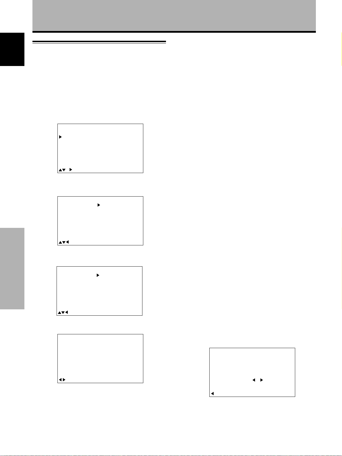
1 Press MENU to display the menu screen.
2 Press 5/∞ to select PICTURE, and then press 3.
IN
A
M
P
ICT
S
C
REE
ALLRE
O
WE
P
SETU
U
M
EN
U
MEN
U
E
R
N
S
E
S
AV
R
P
:
MENU O
:
S
ECT
EL
:
C
O
NTRAST
B
R
T
GH
I
OL
C
F
T
I
S
HAR
R
ESET
F
OR
NT
P
T
E
0
:
0
:
0
:
0
:
0
3 Press 5/∞ to select BRIGHT, and then press SET.
IN
A
M
P
ICT
S
C
REE
ALLRE
O
WE
P
SETU
U
M
EN
U
MEN
U
E
R
N
S
E
S
AV
R
P
:
MENU O
:
S
ECT
EL
:
C
O
NTRAST
B
R
T
GH
I
OL
C
T
E
OR
T
NT
I
S
P
HAR
R
ES
E:T
F
F
S
ADJUST
ET
0
:
0
:
0
:
0
:
0
4 Press 2/3 to adjust the picture quality as desired.
CTU
I
P
BR IGH T
RE
0
S
:EXIT:ADJUST
ET
5 When the setup is finished, press MENU to exit
the menu screen.
Checking supplied accessories
Check that the following accessories were supplied.
About operations in this manual
Operations in this manual are outlined in step by step
numbered procedures. Most of the procedures are
written in reference to the remote control unit unless the
button or control is only present on the main unit.
However, if a button or control on the main unit has the
same or similar name as that on the remote control unit,
that button can be used when performing operations.
2
<ARE1351> En
1 Pin/BNC conversion adaptor x 1
2 Screw rivets x 8
3 Connector cover x 1
÷ Operating Instructions
Page 7
Part Names and Functions
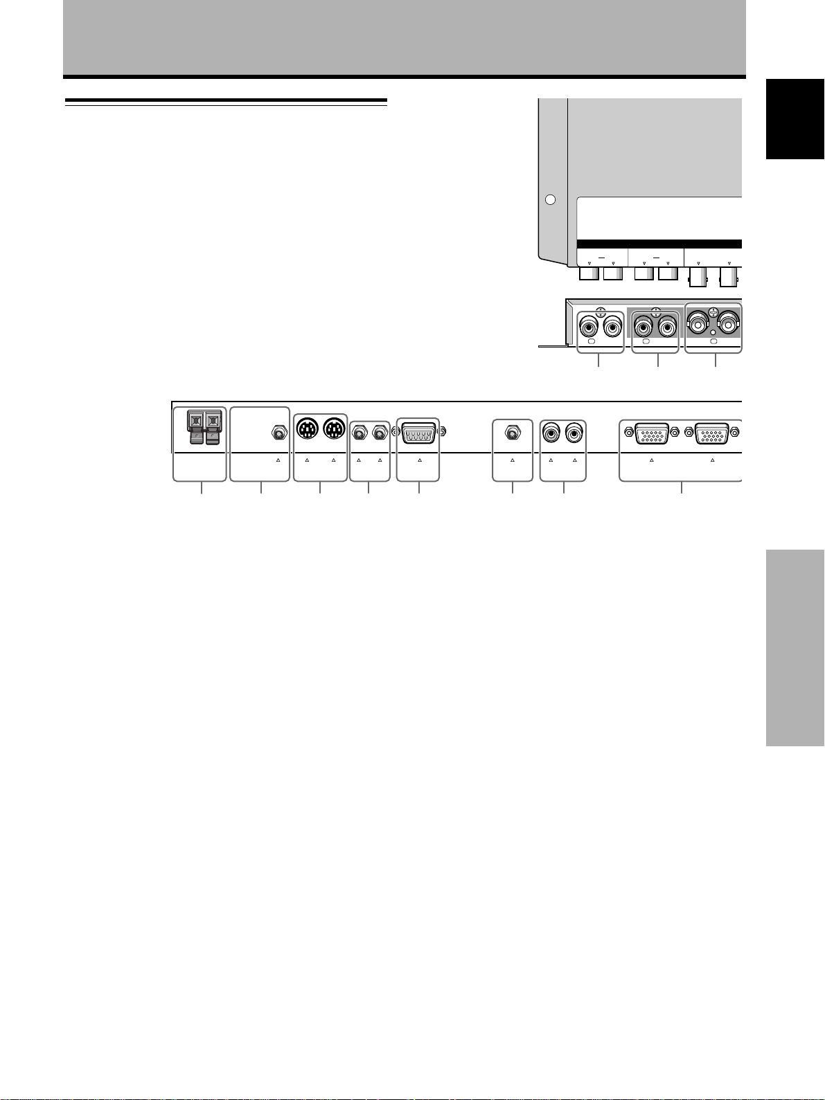
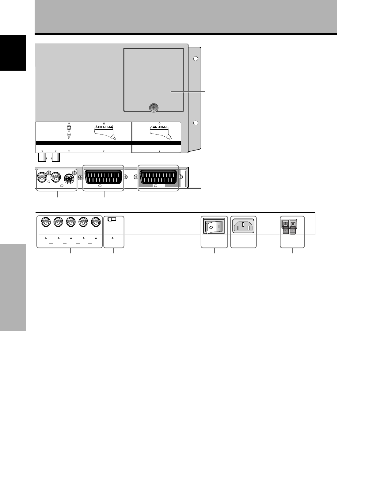
Connection panel (PDP-502MXE & PDA-5001)
For details regarding a specific connection format, refer to
the page written in parenthesis. Additional descriptions
may be found in the instruction manual included with the
plasma display, PDP-502MXE.
+–
SPEAKER
R
8 Ω – 16 Ω
4 -098765
AUDIO OUTPUT
IN
OUT
COMBINATION
IN
OUT
CONTROL
RS-232C
(INPUT 4)
R – L
(INPUT 3)
AUDIO INPUT
AUDIO
R
AUDIO
R
L
1 2 3
ANALOG
R G B
INPUT4
English
INPUT 1INPUT 2
VIDEO
OUT
OUTPUT
ANALOG
(
R G B
IN
ININ OUTAUDIO 11INAUDIO2
(
L
1 AUDIO INPUT (Pin jacks)
Use to obtain sound when INPUT2 (BNC/S) is
selected. Connect the audio output jack of
components connected to INPUT2 (BNC/S) to these
jacks (page 12).
2 AUDIO INPUT (Pin jacks)
Use to obtain sound when INPUT1 (BNC) is selected.
Connect the audio output jack of components
connected to INPUT1 (BNC) to these jacks (page 12).
3 INPUT1 (BNC)
For connection of components that have a composite
video output jack (page 8).
Use the INPUT1 OUT jack to output the video signal
to an external monitor or other component.
Note: The video signal will not be output from the
INPUT1 OUT jack when the main power of the plasma
display is off or in standby mode .
4 SPEAKER (R) terminal
For connection of an external right speaker. Connect a
speaker whose impedance is 8 -16 Ω.
5 AUDIO OUTPUT (Stereo mini jack)
Use to output the audio of the selected source
component connected to this unit.
6 COMBINATION IN/OUT
DO NOT MAKE ANY CONNECTIONS TO THESE
TERMINALS.
These terminals are used in the factory setup.
7 CONTROL IN/OUT
For connection of PIONEER components that bear the
Î mark. Making CONTROL connection enables control
of this unit as a component in a system.
8 RS-232C
DO NOT MAKE ANY CONNECTIONS TO THIS
TERMINAL.
This terminal is used in the factory setup.
9 AUDIO INPUT (Stereo mini jack)
Use to obtain sound when INPUT4 is selected.
Connect the audio output jack of components
connected to INPUT4 to this jack (page 12).
0 AUDIO INPUT (Pin jacks)
Use to obtain sound when INPUT3 is selected.
Connect the audio output jack of components
connected to INPUT3 to these jacks (page 12).
Note: The left audio channel (L) jack is not compatible
with monaural input sources.
- INPUT4
For connection of a personal computer (PC) or similar
component. Make sure that the connection made
corresponds to the format of the signal output from
the connected component (page 9).
Use the INPUT4 OUTPUT terminal to output the video
signal to an external monitor or other component.
Note: The video signal will not be output from the
INPUT4 OUTPUT terminal when the main power of
the plasma display is off or in standby mode .
<ARE1351> En
Part Names and Functions
3
Page 8
Part Names and Functions
English
S-VIDEOCY
S-VIDEO SCARTSCART2 2 1CY
= ~ ! @
G B R
[ON SYNC] [H/V SYNC]
INPUT3
= INPUT2 (BNC/S)
For connection of components that have an S-video
output jack or Y/C separate video output jacks (page
8).
Note: Do not use both the S-VIDEO jack and the BNC
jacks in parallel. Doing so may cause this unit to
Part Names and Functions
malfunction or become damaged.
~ INPUT2 (SCART)
For connection of a VCR or similar component
compatible with SCART connections (page 8).
INPUT 2
HD VD
SCART
75Ωj2.2kΩ
$ % ^ &#
INPUT 1
SCART
MAIN POWER
OFF ON
AC INLET
SPEAKER
8 Ω – 16 Ω
+–
L
$ Synchronizing signal impedance selector switch
Depending on the connections made at INPUT3, it
may be necessary to set this switch to match the
output impedance of the connected component’s
synchronization signal.
When the output impedance of the component’s
synchronization signal is above 75 Ω, set this switch
to the 2.2 kΩ position (page 10).
% MAIN POWER switch
Use to switch the main power of the unit on and off.
! INPUT1 (SCART)
For connection of an AV component compatible with
SCART connections (page 8).
@ Video box connection cover
Remove when connecting this unit to the plasma
display, PDP-502MXE (page 5).
# INPUT3
For connection of components that have RGB or
component output jacks such as a personal computer,
DVD player, or external RGB decoder (page 9).
4
<ARE1351> En
^ AC INLET
Use to connect a power cord to an AC outlet.
& SPEAKER (L) terminal
For connection of an external left speaker. Connect a
speaker that has an impedance of 8 -16 Ω.
Page 9
Installation and Connections
Connecting this unit to the monitor
This unit is to be used only when connected to the
plasma display, PDP-502MXE. Follow the procedure on
this page to connect this unit to the plasma display.
Before connecting this unit to the display, please be
sure to do the following:
÷ Undo any component or personal computer
connections that may have already been made to the
plasma display.
÷ Make sure that the power of the plasma display is
turned off, and is unplugged from the wall outlet.
Precautions when connecting this unit to the display
When the covers on this unit and/or the display are
opened to make connections, be sure to avoid letting the
screw rivets or their respective parts fall into openings on
the units.
CAUTION
This unit is designed only for connection to the plasma display,
PDP-502MXE. Do not alter or modify this unit in any way as it
may cause this unit to perform abnormally and/or may cause the
plasma display to malfunction.
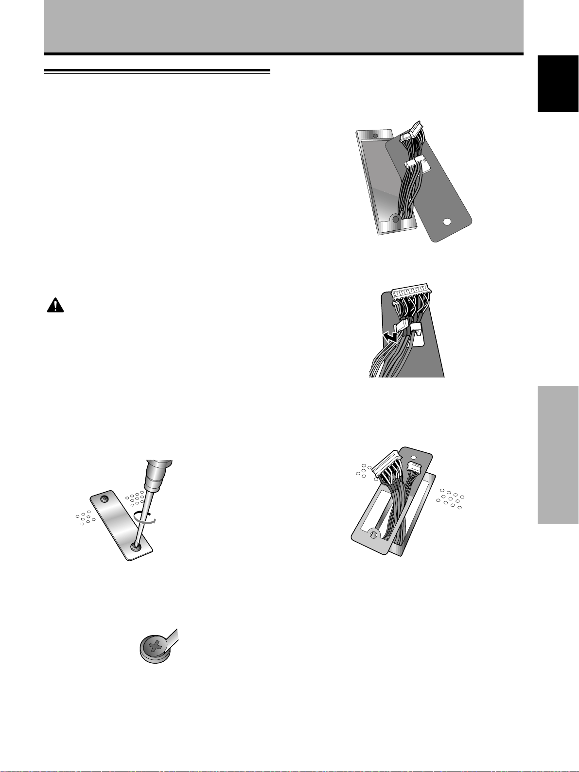
2 Remove the cover plate on the back panel of the
plasma display.
The two cable connectors are attached to the inside of
the cover plate.
Français English
3 Separate the two connector cables from the cover.
To connect this unit to the plasma
display PDP-502MXE
1 Remove the cover plate on the back panel of the
plasma display.
Unscrew using a
philips screwdriver
(“+” head).
Note
If for some reason the screws cannot be unscrewed, use a tool
or other object with a tip flat enough to fit between the screw
and rivet and pry the screw out as shown below.
4 Pull the two connector cables through the slot on
the connector cover included with this unit.
Installation and Connections
<ARE1351> En
5
Page 10
Installation and Connections
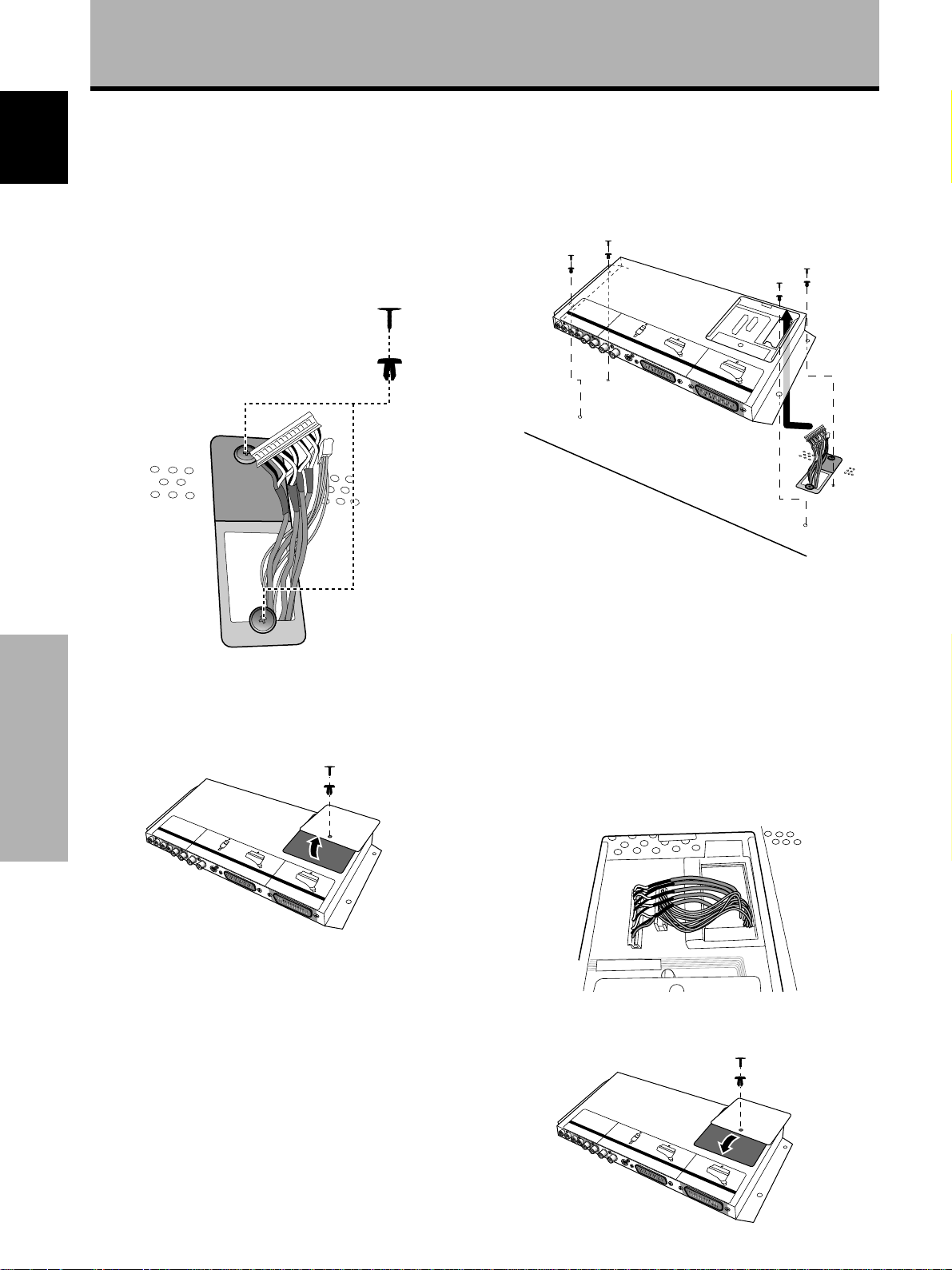
5 Secure the connector cover onto the display with
English
2 of the included screw rivets.
1 Separate the screw from the rivet using a philips
screwdriver.
2 Push the rivet section through the indicated holes
cover plate and into the plasma display until it
snaps in completely.
3 Push the screw section into the rivet to secure the
connection.
3
2
6 Remove the cover on this unit.
When the cover is removed, the two connector
terminals should be clearly visible.
7 Align the holes on this unit with the
corresponding holes on the rear panel of the
plasma display and secure this unit to the plasma
display using 4 of the included screw rivets.
2
3
1
4
÷ When aligning this unit with the plasma display, be sure
to bring the two connector cables through this unit.
÷ Attach the screw rivets in the numbered order
shown above. The procedure for attaching the
screw rivets is described in step 5.
÷ When connecting this unit to the plasma display,
make sure that the cable connectors are not
pinched between the two units.
Installation and Connections
8 Connect the connector cables to the respective
terminals located on the inside of this unit.
Make sure that connections are made correctly and
securely.
9 Replace the cover of this unit.
Connection of this unit is complete.
6
<ARE1351> En
Page 11
About the input jacks
Connect the output jacks of components to the input
jacks of this unit and the plasma display following the list
below (pages 8 to 10).
Installation and Connections
Input jack
INPUT2
(SCART)
*2
*2
INPUT1
(SCART)
INPUT2
(BNC/S)
Connected
component
and signals
AV component
Composite video
S video
Y/C separate video
Component
RGB
Personal computer
(PC)
Composite video
S video
RGB
*1 Although INPUT3/INPUT4 are compatible with various kinds
of signals, setup using the on-screen menu is necessary after
connections are made in order match the characteristics of
the source component (page 15).
*2 Depending on the video output board of the computer, this
type of connection may not be possible.
*3 INPUT4 is compatible with Microsoft’s Plug & Play (VESA
DDC 1/2B).
INPUT1
(BNC)
INPUT3
*1
INPUT4
*3
*1
Français English
INPUT1 and INPUT2 jacks are compatible with the
following TV systems: NTSC, PAL, SECAM and
4.43NTSC. Normally, this unit is capable of automatic
signal detection to adjust for differences in the
systems. However, it is also possible to set the
system. For details, please refer to “Setting the
regional TV system format” on page 23.
Note
INPUT1 (SCART) RGB input is not compatible with G on SYNC
signals.
Installation and Connections
<ARE1351> En
7
Page 12
Installation and Connections
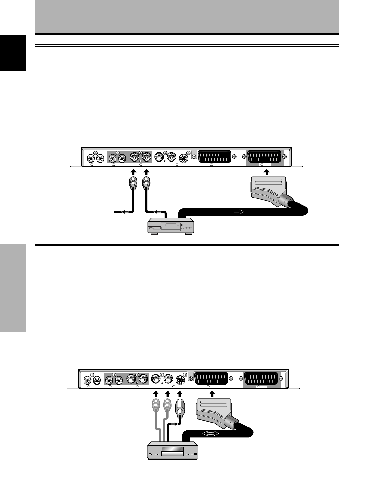
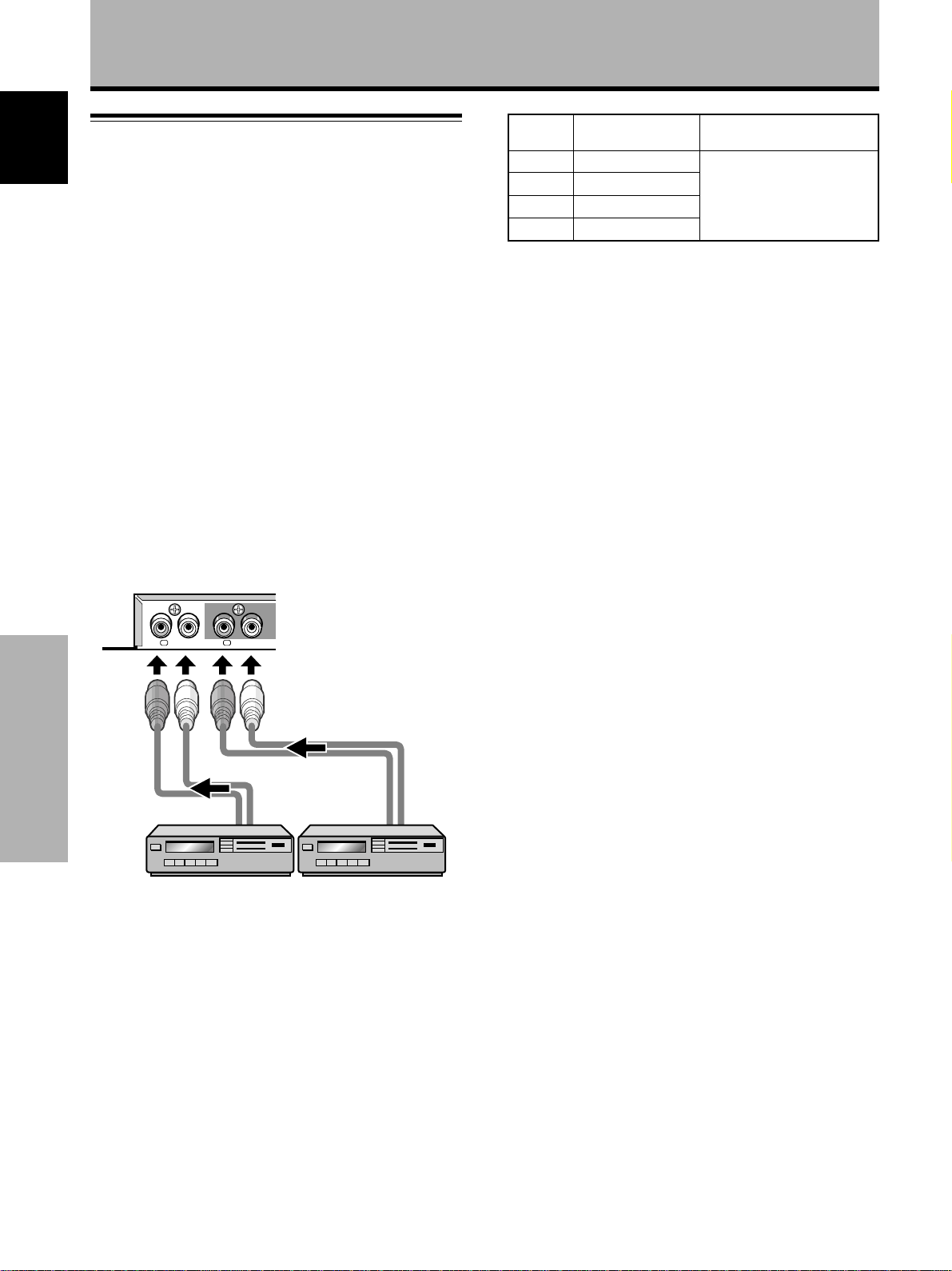
Connection to INPUT1
English
Connect an AV component that has a video output jack to
the INPUT1 jacks on this unit. The following two types of
connections are available:
÷ BNC jack connection
÷ SCART jack connection
After connections are made, on-screen setup is
necessary to assign which jack is to be used (page 14).
To a separate monitor or
video recording device
AV component
The INPUT1 (SCART) jack is compatible with stereo audio
signals (L/R), composite video, and RGB video signals.
The INPUT1 (BNC) jack is compatible with composite
video signals.
The INPUT1 OUT jack (BNC) can be used to output the
video signal to a separate monitor or video recording
device.
Note
A video signal will not be output from the OUT [INPUT1] jack
when the main power of this unit is off or in standby mode.
S-VIDEO SCARTSCART2 2 1CYININ OUTAUDIO 11INAUDIO2
Connection to INPUT2
Connect an AV component that has a video output jack to
the INPUT2 jacks on this unit. The following two types of
connections are available:
÷ BNC jack or S-video jack connection (BNC/S)
÷ SCART jack connection (for connection to VCR)
After connections are made, on-screen setup is
necessary to assign which jack is to be used (page 14).
Installation and Connections
The INPUT2 (SCART) jack is compatible with stereo audio
signals (L/R), composite video, and Y/C separate signals.
Additionally, a stereo audio signal and composite video
signal are output from the INPUT2 (SCART) jack making it
suitable for connection to a VCR.
Connect an AV component that has S-video or Y/C
separate video output jacks to the BNC/S input jacks on
this unit. (The INPUT2 S-VIDEO jack is compatible with S2
output signals.)
Note
Do not use both the S-VIDEO jack and the BNC jacks in parallel.
Doing so may cause this unit to malfunction or become
damaged.
S-VIDEO SCARTSCART2 2 1CYININ OUTAUDIO 11INAUDIO2
8
<ARE1351> En
VCR
Page 13
Installation and Connections
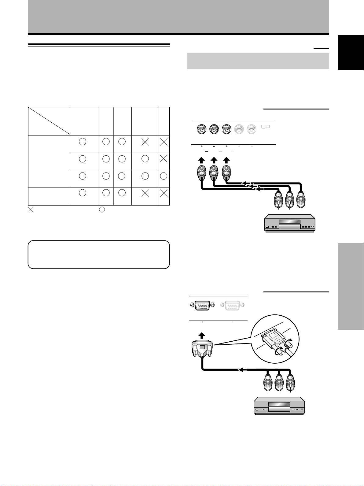
Connection to INPUT3 and INPUT4
Various components can be connected to the INPUT3 and
INPUT4 jacks. After connections are made, on-screen
setup is necessary to match the characteristics of the
connected component. Please see page 15 for on-screen
setup after connection.
INPUT3
jack
Output source
Video component/
personal
computer (PC)
with RGB output
Video component
with component
video output
: Do not connect anything. : Connect to this jack.
Note
Components compatible with INPUT3 are also compatible with
INPUT4.
For the screen sizes and input signals that
INPUT3 and INPUT4 are compatible with, please
refer to Supplement 1 (page 26).
[ON SYNC]
GBR
G ON SYNC
G
Y
(CB/PB)R(CR/PR)
R
B
RG
B
B
[H/V SYNC]
HD VD
H/V SYNC
HD
VD
Connection to AV components
Connection to AV component that has
component video jacks
Make component video connections for AV components
such as DVD and LD players or similar components with
component video output capability to the INPUT3 or
INPUT4 RGB jacks.
When connecting to INPUT3
G B R HD VD
INPUT3(ON SYNC) (H/V SYNC)
On-screen setup is necessary after connection.
Please see page 15.
INPUT3 jacks are all BNC jacks.
If necessary, use pin/BNC conversion adapters (1 (one)
included) to make connections.
75Ωj2.2kΩ
Y CB/P
C
B
R/PR
Français English
When connecting to INPUT4
ANALOG
R G B
INPUT4
OUTPUT
ANALOG
(
R G B
(
CR/P
B/PB
R
Y
C
On-screen setup is necessary after connection.
Please see page 15.
Installation and Connections
9
<ARE1351> En
Page 14
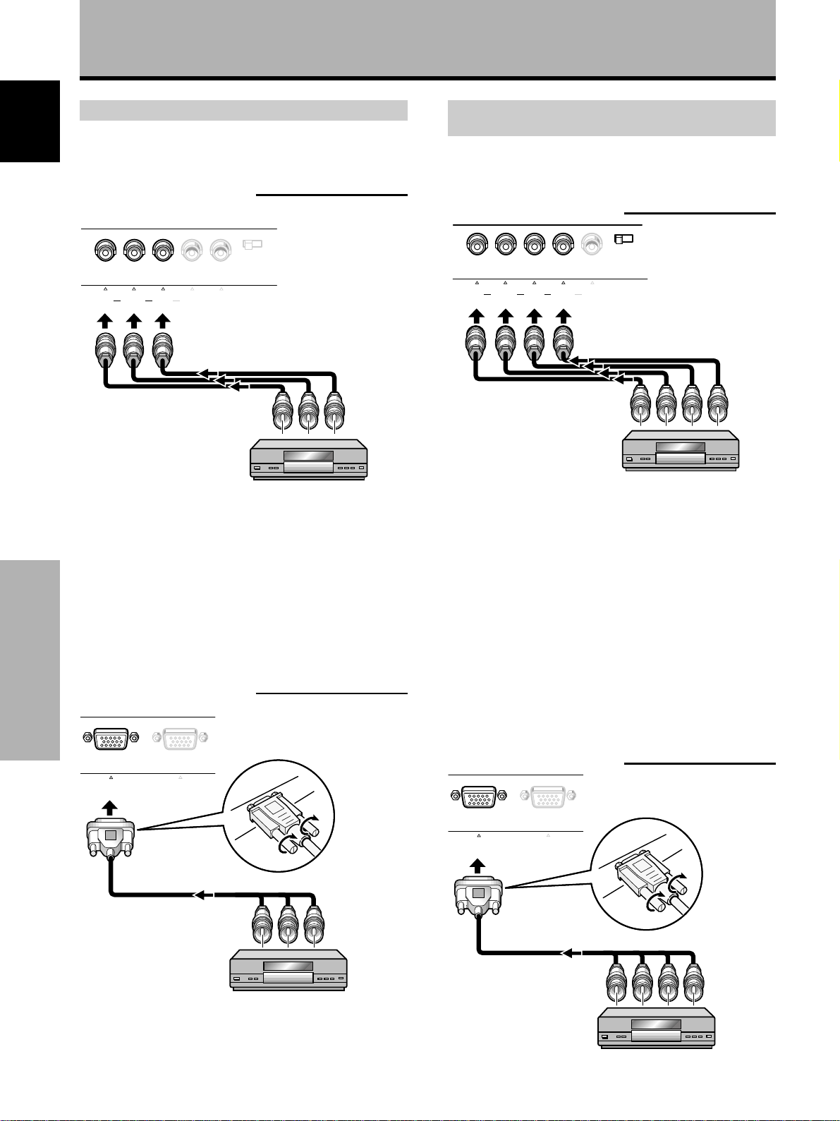
Installation and Connections
Connection of G ON SYNC analog RGB source
Make G ON SYNC connections for an AV component with
English
output that has the synchronization signal layered on top
of the green signal.
When connecting to INPUT3
G B R HD VD
INPUT3(ON SYNC) (H/V SYNC)
On screen setup is necessary after connection.
Please see page 15.
Notes
÷ When making G ON SYNC connections, do not make any
connections to the VD or HD jacks. If connections are made,
the picture may be not displayed normally.
÷ When using a computer connected by the G ON SYNC
connection, on-screen adjustment for G ON SYNC is
necessary (page 16).
Please read your PC’s instruction manual throughly.
When connecting to INPUT4
Installation and Connections
ANALOG
R G B
INPUT4
OUTPUT
ANALOG
(
R G B
(
75Ωj2.2kΩ
Connection of composite SYNC analog RGB
source
Make composite SYNC connections for a component
with output that has the vertical synchronization signal
layered on top of the horizontal synchronization signal.
When connecting to INPUT3
G B R HD VD
INPUT3(ON SYNC) (H/V SYNC)
When using INPUT3, set the impedance selector switch
to match the output impedance of the connected
component’s synchronization signal.
When the output impedance of the component’s
synchronization signal is above 75 Ω, set this switch to
the 2.2 kΩ position.
On-screen setup is necessary after connection.
Please see page 15.
Notes
÷ When making composite SYNC connections, do not connect
anything to the VD jack. If connected to, the picture may not
be displayed properly.
÷ On some types of Macintosh® components, G ON SYNC and
composite SYNC are both output. With this type of
component, please connect using the G ON SYNC connection
(as shown left).
When connecting to INPUT4
75Ω j 2.2kΩ
On screen setup is necessary after connection.
Please see page 15.
10
<ARE1351> En
ANALOG
R G B
INPUT4
OUTPUT
ANALOG
(
R G B
(
On-screen setup is necessary after connection.
Please see page 15.
Page 15
About DVB set top box connection
To ensure proper connection, please carefully read the
instruction manual supplied with the DVB set top box.
The set top box output signals that this unit is compatible
with are as follows.
Signal type
HDTV
SDTV
Dot x Line, Scanning
(aspect)
1920 x 1080 i (16 : 9)
1920 x 1080 p (16 : 9)
1280 x 720 p (16 : 9)
704 x 480 i (16 : 9)
704 x 480 i (4 : 3)
640 x 480 i (4 : 3)
704 x 480 p (16 : 9)
704 x 480 p (4 : 3)
640 x 480 p (4 : 3)
Signal Format
Component
RGB
Composite
S Video
Component
RGB
Component
RGB
INPUT1
(BNC)
Installation and Connections
Jacks where connection is possible
INPUT1
(SCART)
*
INPUT2
(BNC/S)
INPUT2
(SCART)
Français English
INPUT4INPUT3
* INPUT1 (SCART) RGB input is not compatible with G on SYNC
signals.
Installation and Connections
11
<ARE1351> En
Page 16
Installation and Connections
Audio connections
English
Before making connections, be sure to check that the
audio component’s power and the display’s main power is
off.
When this unit is connected to the plasma display,
PDP-502MXE, the following audio connections can be
made.
The following jacks and terminals are located on the
plasma display. For details, please refer to the instructions
supplied with the PDP-502MXE.
÷ Speaker terminals
÷ Audio output jack (stereo mini jack (L/R))
÷ INPUT3 AUDIO INPUT jacks (pinjacks (L/R))
÷ INPUT4 AUDIO INPUT jack (stereo mini jack (L/R))
The following audio input jacks are available on this unit:
÷ INPUT1 AUDIO INPUT jacks (pinjacks (L/R))
÷ INPUT2 AUDIO INPUT jacks (pinjacks (L/R))
Audio connection for component connected to
INPUT1 or INPUT2
PDA-5001
Video
input
INPUT1
INPUT2
INPUT3
INPUT4
Note
The left audio input jack (L) is not compatible with monaural input
sources.
Audio input jacks Sound output
Pin jacks (L/R)
Pin jacks (L/R)
Pin jacks (L/R)
Stereo mini jack (L/R)
Sound of the selected video
input is output from the
• SPEAKER terminals
• Stereo mini jacks (L/R).
When SCART connections are made
When SCART connections are made to INPUT1 and/or
INPUT2, the audio signal is input at the SCART jack, and
therefore it is not necessary to make the audio
connections described on this page.
INAUDIO1INAUDIO2
Installation and Connections
After video and audio connections are made, the audio
corresponding to the selected video source is output from
both the AUDIO OUTPUT jacks (stereo mini jack) and the
SPEAKER jacks on the plasma display.
12
<ARE1351> En
Page 17
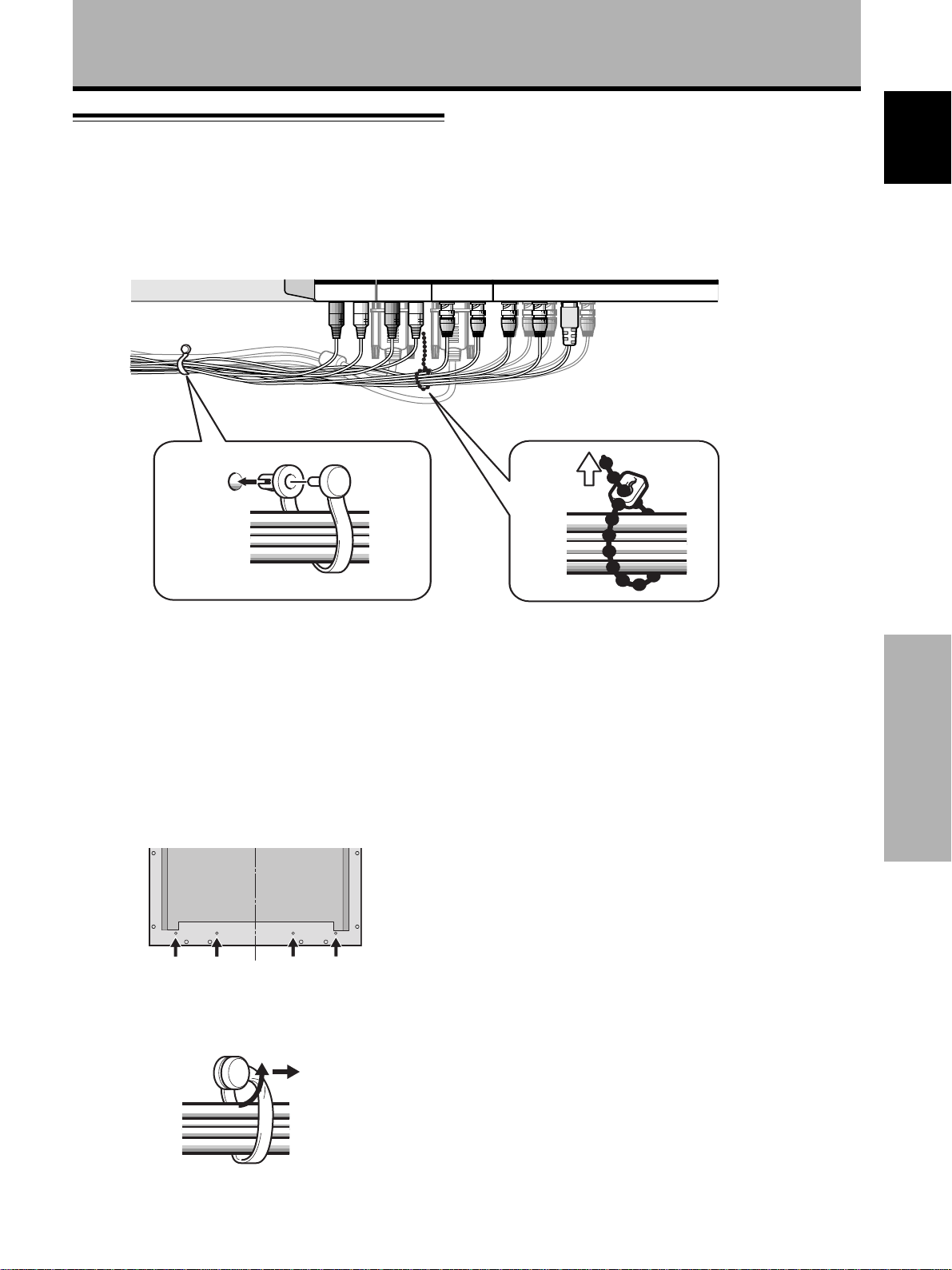
How to route cables
Speed clamps and bead bands are included with the
display for bunching cables together. Once components
are connected, follow the following steps to route cables.
Installation and Connections
1
1
2
1 Organize cables together using the provided
speed clamps.
Insert 1 into an appropriate hole on the rear of the
unit, then snap 2 into the back of 1 to fix the clamp.
Speed clamps are designed to be difficult to undo
once in place. Please attach carefully.
* As viewed from the rear of the display.
Français English
2
2 Bunch separated cables together and secure
them with the provided bead bands.
Note
Cables can be routed to the right or left.
To attach the speed clamps to the main unit
Connect the speed clamps using the 4 holes marked with
÷ below, depending on the situation.
To remove speed clamps
Using pliers, twist the clamp 90° and pull it outward.
In some cases the clamp may have deteriorated over
time and may be damaged when removed.
Installation and Connections
13
<ARE1351> En
Page 18
Setting Up the System
Setting up INPUT1 and INPUT2
English
After components have been connected to INPUT1 or
INPUT2, on-screen setup is necessary.
÷ Set whether the BNC jacks or SCART jack is being used
for both INPUT1 and INPUT2
÷ If the SCART jack is used, set the video signal type to
correspond to the video signal output of the connected
components.
Follow the procedure described below and make settings
as they apply to the type of components connected.
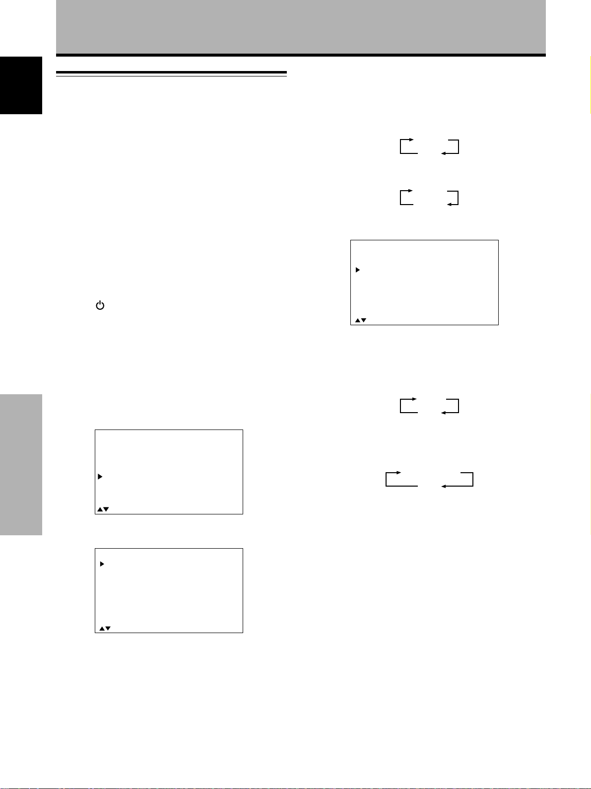
7 Press SET to select the appropriate input jack.
Selection will change as follows each time SET is
pressed.
When INPUT1 is selected
SCART
BNC
When INPUT2 is selected
SCART
BNC/S
8 Press 5/∞ to select SCART INPUT.
1 Switch MAIN POWER on the connection panel to
the on position to turn on the display’s main
power.
The STANDBY/ON indicator lights red.
2 Press STANDBY/ON to put the display in the
operation mode.
The STANDBY/ON indicator turns green.
3 Select INPUT1 or INPUT2.
4 Press MENU to display the menu screen.
The menu screen appears.
5 Press 5/∞ to select SET UP, and press SET.
A
M
P
S
ALLRE
P
SETU
M
Setting Up the System
EN
IN
ICT
C
REE
O
WE
U
U
MEN
U
E
R
N
S
E
S
AV
R
P
:
MENU O
:
S
ECT
EL
T
E
F
F
:
S
ET
X
N
E
T
6 Press 5/∞ to select TERMINAL.
SET
N
TERMI AL
COLGORUPS
SCRA
T
HIH
I
O
C
YSTE
NPUT
NTRA
M
T:OF
S
:SCA
:AUT
:AUT
RT
O
O
F
SET
TERMI AL
COLGORUPS
SCRA
HIH
EXI
N
T
I
O
C
T
:S SEEEGNAHC:TLECT
YSTE
NPUT
NTRA
M
T:OF
S
:SCA
:AUT
:AUT
RT
O
O
F
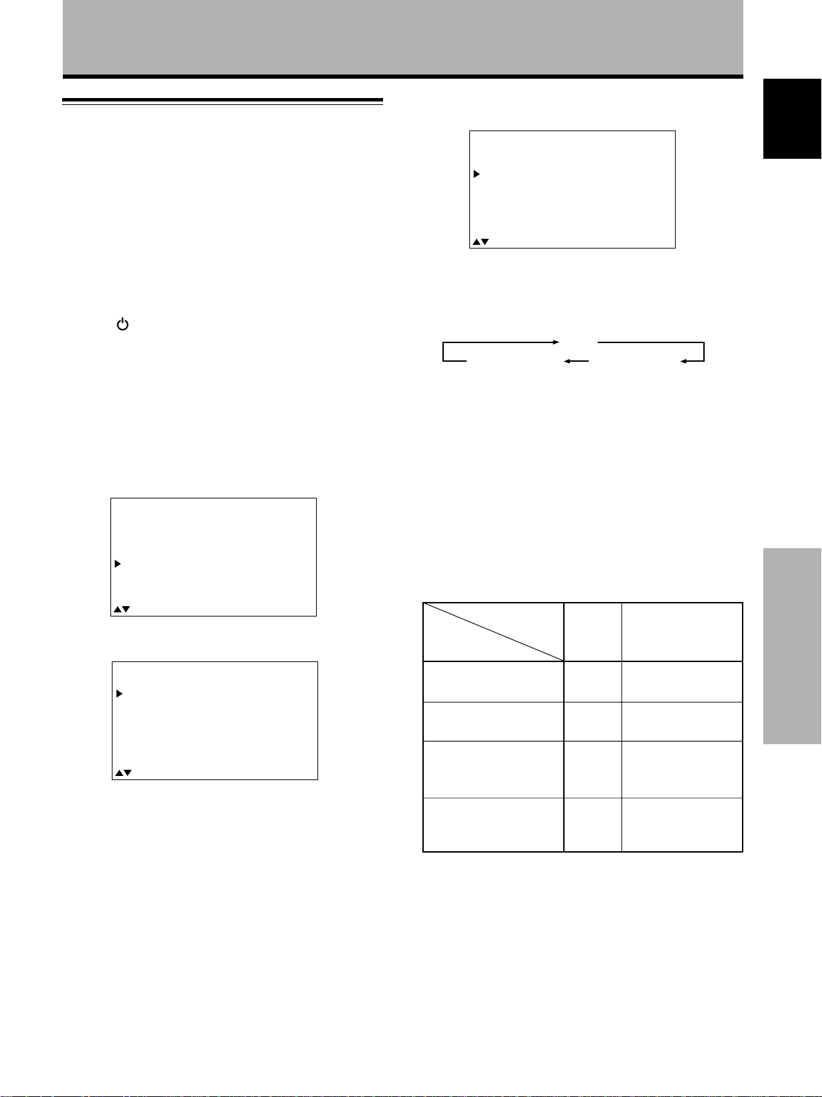
9 Press SET to select the appropriate signal.
Selection will change as follows each time SET is
pressed.
When INPUT1 is selected
AUTO
RGB
(When AUTO is selected, this unit automatically
switches to RGB when an RGB signal is input.)
When INPUT2 is selected
COMPOSITE
Y/C
10 When the setup is completed, press MENU to exit
the menu screen.
Note
Make these adjustments for each input (INPUT1 and INPUT2).
14
<ARE1351> En
EXI
T
:S SEEEGNAHC:TLECT
Page 19
Setting up INPUT3 and INPUT4
After components have been connected to INPUT3 or
INPUT4, on-screen setup is necessary.
Follow the procedure described below and make settings
as they apply to the type of components connected.
1 Switch MAIN POWER on the connection panel to
the on position to turn on the monitor’s main
power.
The STANDBY/ON indicator lights red.
2 Press STANDBY/ON to put the monitor in the
operation mode.
The STANDBY/ON indicator turns green.
3 Select INPUT3 or INPUT4.
Setting Up the System
8 Press 5/∞ to select SIGNAL.
TU
E
S
P
I
T
ERM
A
N
S
SI
C
HH
EX
G
E
N
TTI
G
N
AL
L
AM
P:M
C
I
G
I
T
:
S
ECT
EL
L
NTO
C
:BN
:VIDE
:
R
B
G
O
DE1
R
AS
T
S
ET
O
:
FFO
:
C
A
E
H
NG
9 Press SET repeatedly to select the input signal
format.
Selection will change as follows each time SET is
pressed.
RGB
COMPONENT 2
The table below shows what settings are appropriate
and available for the type of connections made.
COMPONENT 1
Français English
4 Press MENU to display the menu screen.
The menu screen appears.
5 Press 5/∞ to select SET UP, and press SET.
MEN
U
REE
WE
R
:
U
MENU O
:
S
R
N
P
EL
E
S
S
U
E
T
AV
ECT
E
F
F
:
S
ET
X
N
E
T
IN
A
M
P
ICT
S
C
ALLRE
O
P
SETU
M
EN
6 Press 5/∞ to select SETTING.
TU
E
S
Please note that the TERMINAL setting is set to
“BNC” when INPUT3 is selected, and ”D-SUB” when
INPUT4 is selected.
P
I
T
S
SI
C
H
EX
ERM
E
L
A
N
G
N
TTI
G
N
AL
AM
P:M
O
C
I
G
H
I
T
:
S
ECT
EL
L
NT
C
:BN
:VIDE
:
R
B
G
O
D
R
A
S
T
S
ET
O
1
E
:
O
:
C
H
A
E
NFFG
10 When the setup is completed, press MENU to exit
the menu screen.
Notes
÷ Make this setup for each input (INPUT3 and INPUT4).
÷ When selecting a PC signal or when SETTING is set to “PC”,
“COMPONENT” cannot be selected.
÷ Please refer to page 16 for details concerning CLAMP (G ON
SYNC) setup.
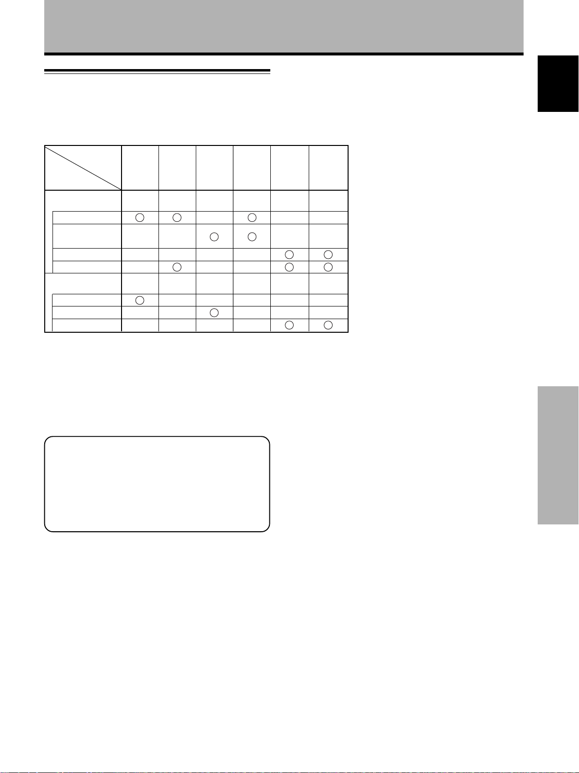
Set SETTING and SIGNAL as follows.
SET UP
Connected
component
Component video output
of a DVB set top box
Component video output
of a DVD player, etc.
RGB video output of a
video deck etc., with RGB
output
RGB video output of a PC
SETTING
VIDEO COMPONENT 1*
VIDEO
VIDEO
PC
SIGNAL
COMPONENT 2*
RGB
RGB (Fixed to RGB
when SETTING is set
to “PC”.)
Setting Up the System
7 Press SET to select either “PC” or “VIDEO”.
When a personal computer is connected, set to “PC”.
When a component other than a personal computer is
connected, set to “VIDEO”.
Note
Steps 6 to 7 are necessary when inputting a signal of horizontal
frequency 31.5 kHz/vertical frequency 60 Hz.
For signals of other frequencies, settings are done automatically,
and therefore cannot be performed.
* Select either COMPONENT 1 or 2 depending on which setting
provides the most natural picture color for the component
connected.
Note
When a DVB set top box is connected, please also refer to the
instruction manual supplied with the set top box.
15
<ARE1351> En
Page 20

Setting Up the System
G ON SYNC setup (CLAMP)
English
The RGB video signal is normally composed of 5 signals:
R, G, B, HD and VD. With G ON SYNC connection,
however, the signal is composed of 3 signals: R, G (G, HD
and VD combined) and B.
If the component being used is a model where G ON
SYNC connection is carried out, on-screen setup is
necessary.
Setup of G ON SYNC (CLAMP) connection
1 Press MENU to display the menu screen.
The menu screen appears.
2 Press 5/∞ to select SET UP, and press SET.
Notes
÷ Make this G ON SYNC setting for each applicable input
(INPUT3 and INPUT4).
÷ When using this setup, be sure to carefully check the signal
output of the component that you are using. For details, please
refer to the instruction manual supplied with the component
you are connecting.
÷ If the screen becomes bright and turns a greenish color, set
CLAMP to MODE2.
÷ G ON SYNC connection is carried out on some Macintosh
computers.
IN
A
M
M
MEN
U
P
ICT
S
C
REE
ALLRE
O
WE
P
R
SETU
:
U
MENU O
EN
:
S
R
N
P
EL
E
S
S
3 Press 5/∞ to select CLAMP.
TU
E
S
Setting Up the System
T
S
SI
C
A
H
V
EX
ERM
E
L
B
.
.
:
P
I
N
N
TTI
G
N
AL
AM
P
L
ENHAN
ENHAN
I
T
S
ECT
EL
A
G
4 Press SET to select MODE2.
Mode selection will change as follows each time SET
is pressed.
3 MODE1 (Normal connection)
MODE2 (G ON SYNC connection) 2
U
E
T
AV
ECT
L
CE
CE
E
F
:BN
:PC
:
R
:M
:
O
:
:
F
S
G
O
F
S
ET
C
B
DE1
F
0
0
ET
:
X
N
E
T
:
C
A
E
H
NG
5 When the setup is completed, press MENU to exit
the menu screen.
16
<ARE1351> En
Page 21
Operations
Selecting an input source
This section explains the basic operation of this unit when
connected to the monitor. Outlined on this page is how to
turn the monitor’s main power on and off, put this unit in
the operation or standby mode and how to select
connected components.
Before you begin, make sure you have:
÷
Made connections from the monitor and video box to AV
components and/or a personal computer.
÷ Set up the on-screen menu to input signals from
components connected to INPUT1 through INPUT4 as
described in the section “Setting Up the System” on
page 14.
If no connections are made to these terminals,
on-screen setup is not necessary.
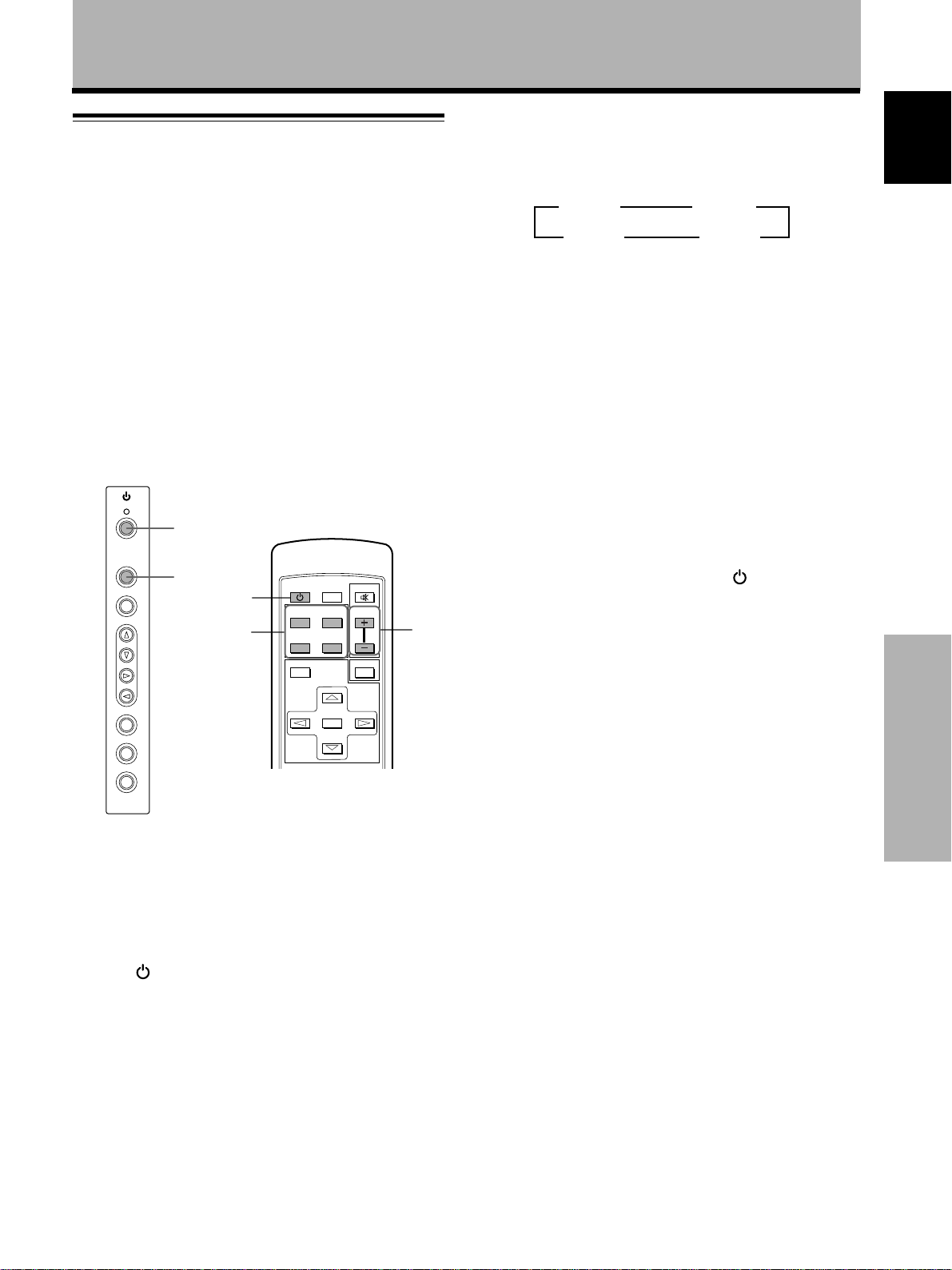
STANDBY/ON
2,5
INPUT
MENU
ADJUST
3
2,5
STANDBY
SCREEN
INPUT
(D-sub)
MENU
SIZE
Y/C
RGB
MUTING
VOL
4
DISPLAY
/ON
VIDEO
12
3
RGB
(BNC)
34
3 Press INPUT on the remote control unit or the
main unit to select the input.
On the main unit, input changes each time INPUT is
pressed as follows.
3 INPUT23 INPUT1
INPUT4 2 INPUT3 2
÷ Input cannot be changed when a menu screen is
displayed.
÷ When the SCART terminal is selected as the input
for INPUT1 and/or INPUT2 in the system settings
described on page 14, the auto function feature is
capable of automatic input switching when the
connected component is operated.
÷ When a signal from a personal computer is input, if
the signal is not compatible with the monitor, “OUT
OF RANGE” will appear on the screen.
4 Use VOLUME +/– on the remote control unit to
adjust the volume.
If no audio connections are made to this unit, this step
is not necessary.
5 When viewing is finished, press STANDBY/ON
to put the unit in standby mode.
The STANDBY/ON indicator will blink and then remain
lit (red) indicating that the standby mode is engaged.
Operation is not possible while the STANDBY/ON
indicator is blinking (red).
English
SET
SIZE
DISPLAY
Operation panel of the
plasma display monitor,
PDP-502MXE
Remote control unit
supplied with PDP-502MXE
SET
1 Switch MAIN POWER on the monitor to the on
position to turn the main power on.
The STANDBY/ON indicator lights red.
2 Press STANDBY/ON to put the monitor in the
operation mode.
The STANDBY/ON indicator turns green.
6 Switch MAIN POWER on the monitor to the off
position to turn the main power off.
Operations
CAUTION
Please do not leave the same picture displayed on the screen for
a long time. Doing so may cause a phenomenon known as
“screen burn” which leaves a ghost, or residual, image of the
picture on the screen.
17
<ARE1351> En
Page 22
Operations
Screen size selection
English
When this unit is connected to the plasma display
PDP-502MXE, it incorporates screen modes of various
height and width ratios. For optimal viewing, we
recommend that you select the screen mode that best
matches the video source that you are viewing. Although
these modes are designed for full display of a picture on a
wide screen, it is our hope that you make use of them
with a full understanding of the manufacturer’s intentions.
Changing the screen size
(For screen sizes when the video signal of a personal
computer is input, please refer to the personal computer
input signal correspondence chart in the instruction
manual supplied with the PDP-502MXE.)
Notes
÷ When the NATURAL WIDE, CINEMA WIDE, ZOOM, or FULL
setting is used to display a non-wide screen 4:3 picture fully on
a wide screen, a portion of the picture may be cut off or
appear deformed.
÷ Please note that when this unit is used for business or public
viewing purposes and the CINEMA WIDE mode or ZOOM
screen modes are used to compress or stretch the screen
picture, this may violate the rights of the author protected
under copyright law.
The size of the picture or the picture’s range projected on
the screen can be changed between 5 screen sizes
described in the table on this page.
Press SCREEN SIZE to select the size.
The screen size changes each time SCREEN SIZE on the
remote control, or SIZE on the unit is pressed as follows.
For video signals
3 NATURAL WIDE 3 4:3 NORMAL
For PC signals
3 ORIGINAL 3 4:3 NORMAL
FULL 2ZOOM 2
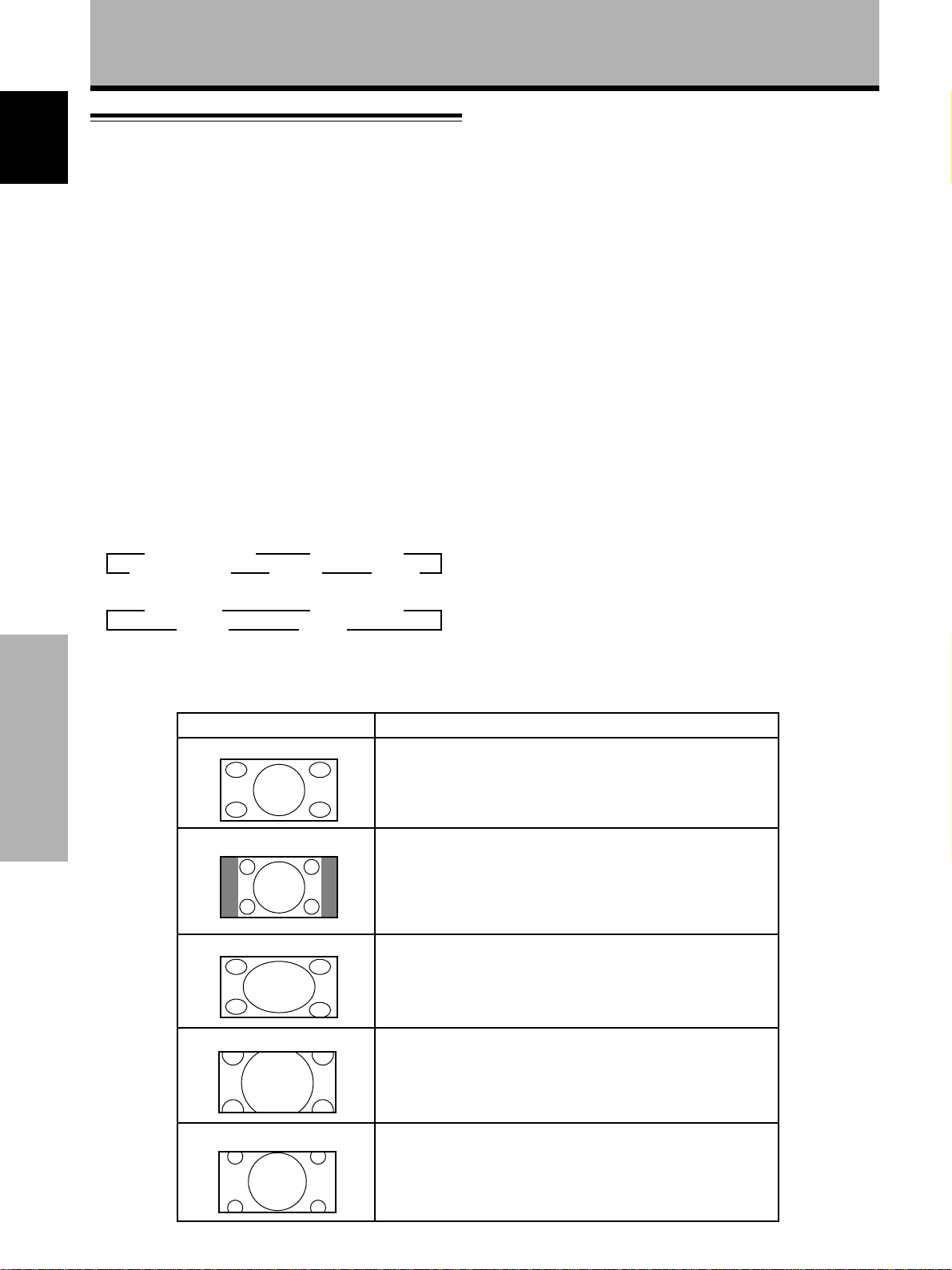
During video signal input
How the picture looks
NATURAL WIDE
Operations
4:3 NORMAL
Moving the screen position
upward or downward
When a vista size movie etc., is viewed at the CINEMA
WIDE or ZOOM setting, the image may not be centered
on the screen, and may extend past the edge of the
screen.
In this case, adjust the screen to an clearly viewable
position using 5/∞.
FULL 2ZOOM 2CINEMA WIDE 2
Suitable for when viewing news or sports programs. Movies or
sports programs can be viewed with an expansive powerful image.
Suitable for when viewing news or sit coms. The video software
can be viewed in its original screen frame size.
(To prevent screen burn on this unit, the displayed position of the
screen frame will be slightly different each time the power is
turned on.)
During personal computer input (1280 x 1024/60Hz only),
even when the ZOOM setting is selected, the position of
the screen can be adjusted by using 5/∞.
18
<ARE1351> En
FULL
ZOOM
CINEMA WIDE
Suitable for wide screen images (squeeze).
Mainly suitable for viewing Cinemascope size and other such movie
images.
Provides a more expansive, powerful image.
Mainly suitable for viewing Vista size and other such movie images.
Provides a more expansive, powerful image. This screen size is
convenient when viewing a Cinemascope size image that has
subtitles.
Page 23
Automatic selection of screen size
according to input signal
By distinguishing between signals such as S1, S2 and
HDTV video signals, etc., screen size is automatically
selected and the following indicators are displayed on the
screen.
Input signal Operation Screen indication
Operations
English
When S1 video signal (squeeze) is input
When S2 video signal (letterbox) is input
When HDTV signal (1920 x 1080 i, 1280 x 720 p,
1920 x 1080 p) is input
When a 16:9 video signal (squeeze) is input at the
SCART jacks (Refer to the instruction manual of the
connected AV component to determine whether it is
compatible with this function is available or not.)
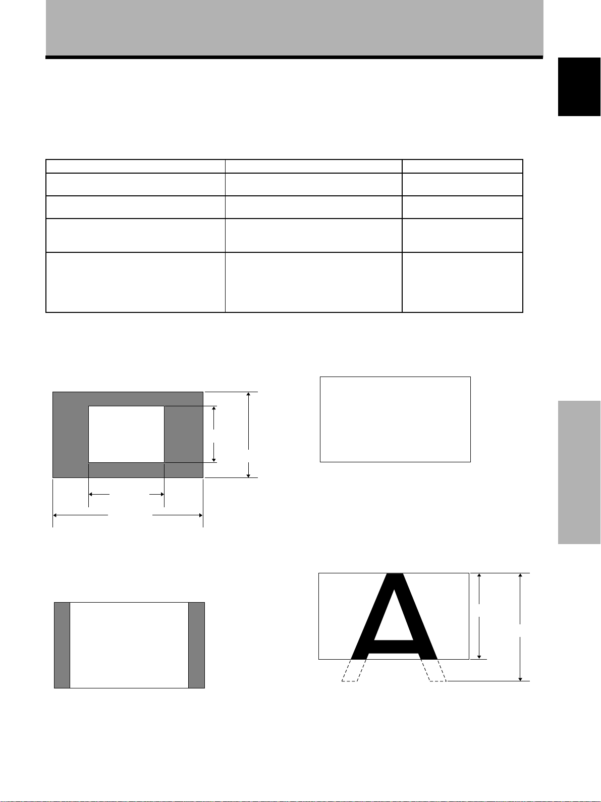
During personal computer signal input
1 ORIGINAL
The input signal and the screen maintain a dot to line ratio
of 1:1 and is thus highly faithful to the source.
A
“FULL” screen size is automatically selected.
“ZOOM” screen size is automatically selected.
“FULL” screen size is automatically selected.
“FULL” screen size is automatically selected.
480 lines
768 lines
FULL (S1)
ZOOM (S2)
FULL (HD)
FULL (AUTO)
3 FULL
The display is presented with a widescreen aspect ratio
of 16:9 and fills the entire screen.
A
640 dots
1280 dots
(Illustration shows 640 x 480 input.)
2 4:3 NORMAL
The display fills the screen as much as possible without
altering the aspect ratio of the input signal.
A
4 ZOOM
The ZOOM setting is available only during personal
computer input (1280 x 1024/60 Hz only).
The input signal and the screen maintain a dot to line ratio
of 1:1. Display is highly faithful to the source. However, in
order to maintain the 1:1 ratio, a portion of the display will
not appear on the screen.
768 lines
1024 lines
Use 5/∞ to adjust the position of the video image on the
screen.
19
<ARE1351> En
Operations
Page 24

Operations
POWER SAVE
English
When this unit is connected to the display, you can use
the POWER SAVE function to put the power mode
automatically in standby mode when a video or computer
signal has not been detected.
(An indication will appear on the screen before the
standby mode is engaged.)
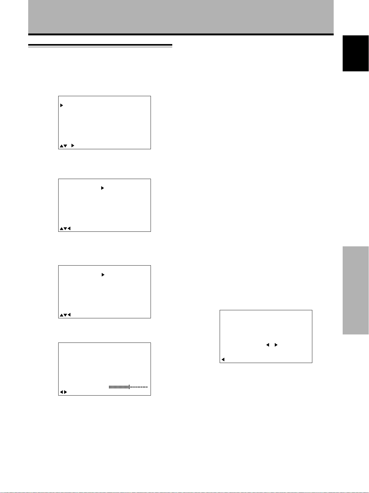
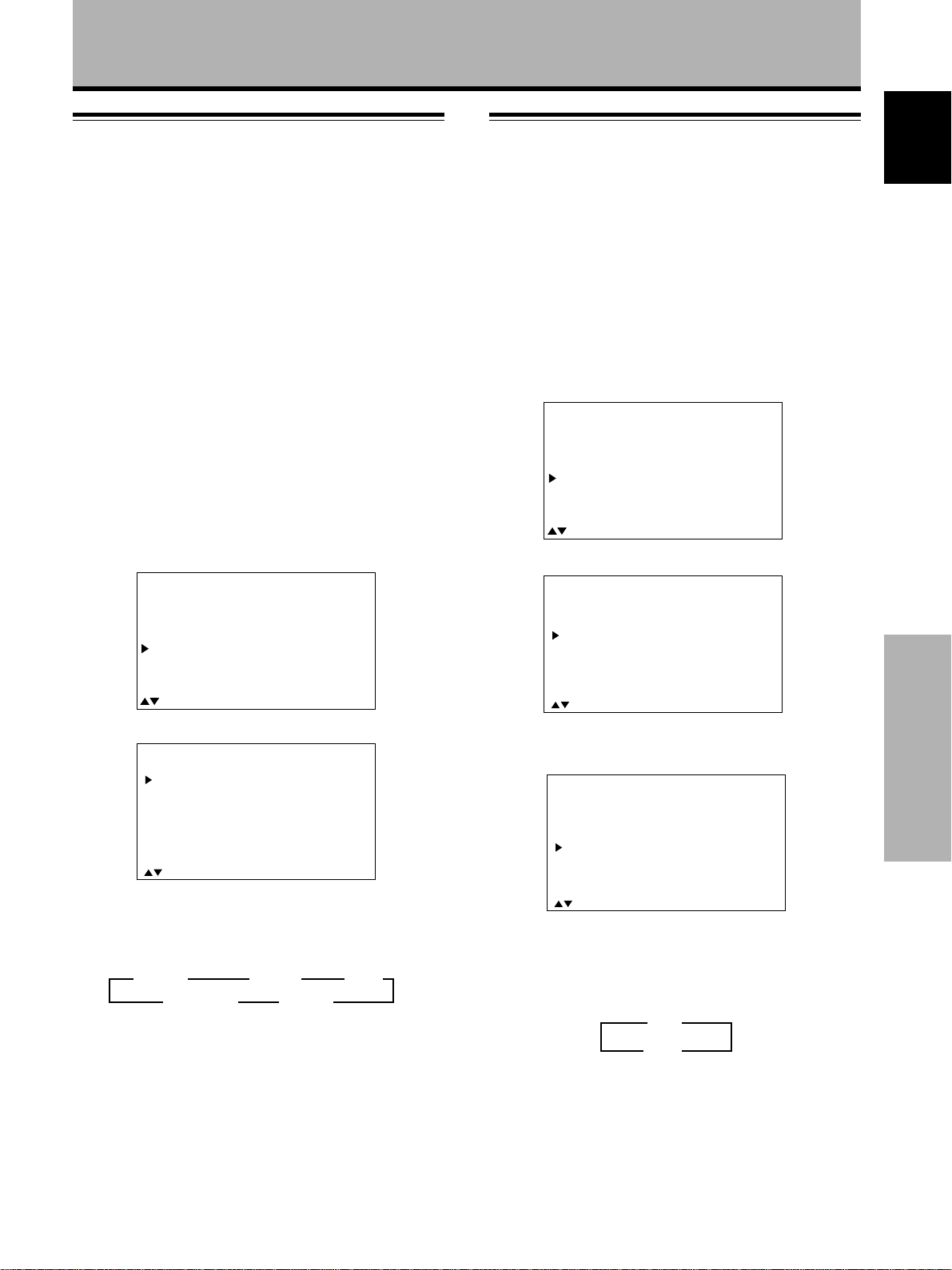
1 Press MENU to display the menu screen.
2 Press 5/∞ to select POWER SAVE, and press SET.
IN
A
M
P
ICT
S
C
REE
ALLRE
O
WE
P
SETU
U
M
EN
U
MEN
U
E
R
N
S
E
S
AV
R
P
:
MENU O
:
S
ECT
EL
T
E
F
F
:
S
ET
X
N
E
T
3 Press 5/∞ to select either “VIDEO” or “PC”.
Select “VIDEO” to set the POWER SAVE mode for
input from video sources, or “PC” to set the POWER
SAVE mode for input from personal computers.
RSA
O
:
MOD
:
MOD
VE
E1
E
2
WE
O
P
V
IDE
P
C
4 Press SET to select the POWER SAVE mode.
When “VIDEO” is selected, the POWER SAVE modes
change as follows.
3 OFF
MODE1 2
÷ When “OFF” is selected, the display will stay in
operation mode regardless of whether a
synchronization signal is input or not.
÷ When “MODE1” is selected, the display will be put
in standby mode automatically if no new
synchronization signal is input for 8 minutes.
When “PC” is selected, the PC POWER SAVE modes
change as follows.
3 OFF
MODE2 2 MODE1 2
÷ When “OFF” is selected, the display will stay in
operation mode regardless of whether a
synchronization signal is input or not.
÷ When “MODE1” is selected, the display will be put
in standby mode automatically if no new
synchronization signal is input for 8 minutes.
÷ When “MODE2” is selected, the display will be put
in the power conservation standby automatically if
no new synchronization signal is input. However, if
the synchronization signal is restored, the display is
put back in operation mode.
Operations
5 When the setup is finished, press MENU to exit
the menu screen.
T
E
XI
:
S
ECT
EL
:
S
C
A
E
H
ET
NG
Note
The POWER SAVE setting is common to all inputs (INPUT1 to
INPUT4).
To put the unit in operation mode again
Press STANDBY/ON on the display or remote control
unit.
If “MODE 2” is selected for PC input, resuming PC
operation or pressing INPUT on the main unit or remote
control unit can also put the unit in operation mode again.
20
<ARE1351> En
Page 25
Display Panel Adjustments
Adjusting the picture quality
1 Press MENU to display the menu screen.
2 Press 5/∞ to select PICTURE, then press 3.
IN
A
M
P
ICT
S
C
REE
ALLRE
O
WE
P
SETU
U
M
EN
3 Press 5/∞ to select the adjustment item, then
press SET.
IN
A
M
P
ICT
S
C
REE
ALLRE
O
WE
P
SETU
U
M
EN
U
MEN
U
E
R
N
S
E
S
AV
R
P
:
MENU O
:
S
ECT
EL
U
MEN
U
E
R
N
S
E
S
AV
R
P
:
MENU O
:
S
ECT
EL
:
C
O
NTRAST
B
R
T
GH
I
OL
C
E
F
E
F
OR
T
NT
I
S
HAR
R
ESET
F
C
O
NTRAST
B
R
I
OL
C
OR
T
NT
I
S
HAR
R
ES
F
S
ET
P
T
GH
P
E:T
ADJUST
T
T
0
:
0
:
0
:
0
:
0
:
0
:
0
:
0
:
0
:
0
PICTURE mode adjustment items
Below are brief descriptions of the options that can be set
in the PICTURE mode.
CONTRAST ············· Adjust according to the surrounding
brightness so that the picture can be
seen clearly.
BRIGHT ··················· Adjust so that the dark parts of the
picture can be seen clearly.
COLOR···················· Adjust to the desired depth. (Setting
to a slightly deep color will create a
natural looking picture.)
TINT························· Adjust so that skin color looks
normal.
SHARP ···················· Normally set to the center position.
To create a softer picture, set to the
left of center. To create a sharper
picture, set to the right of center.
R LEVEL ·················· Adjust the amount of red in the
picture.
G LEVEL ·················· Adjust the amount of green in the
picture.
B LEVEL ·················· Adjust the amount of blue in the
picture.
English
When viewing an image from a personal computer
from INPUT3 or INPUT4, the following screen is
displayed.
A
IN
M
P
ICT
S
C
REE
ALLRE
O
WE
P
SETU
U
M
EN
U
MEN
U
E
R
N
S
E
S
AV
R
P
:
MENU O
:
S
ECT
EL
:
C
ON
R
ST
A
T
B
RI
H
T
G
R
L
V
L
E
F
G
B
R
ESET
F
S
ET
E
L
V
E
E
L
V
E
E
:ADJUS
L
L
T
E
0
:
0
:
0
:
0
:
0
T
4 Press 2/3 to adjust the picture quality as desired.
CTU
I
P
C
Pressing SET returns the display to the step 3 screen.
ON
RE
AST
R
T
0
S
:EXIT:ADJUST
ET
To reset PICTURE mode settings to the default
If settings have been adjusted excessively or the picture
on the screen no longer appears natural, it may prove
more beneficial to reset the PICTURE mode to default
settings instead of trying to make adjustments under
already adjusted conditions.
1 In step 3 in the previous procedure, press 5/∞ to
select RESET, then press SET.
CT
I
P
RUE
A
DJUST
Y
:
S
ECTS
EL
E
R
ES NO
ET:EXI
S
ET?
T
2 Press 2 to select YES, and press SET.
All PICTURE mode settings are returned to the factory
set default.
Display Panel Adjustments
5 When the setup is finished, press MENU to exit
the menu screen.
Note
Make these adjustments for each input (INPUT1 to INPUT4) and
signals.
21
<ARE1351> En
Page 26
Display Panel Adjustments
Adjusting the display image
English
Adjust when INPUT3 or INPUT4 is selected.
(Adjustments on this page cannot be made when INPUT
1 or INPUT 2 is selected. “– – –” is displayed if the
adjustment is not available.)
1 Press MENU to display the menu screen.
5 When adjustment is finished, press MENU to exit
the menu screen.
Note
Make these adjustments for each input (INPUT3 to INPUT4) and
signals.
SCREEN mode adjustment items
Below are brief descriptions of the options that can be set
in the SCREEN mode.
2 Press 5/∞ to select SCREEN, then press 3.
A
IN
M
P
ICT
S
C
REE
ALLRE
O
WE
P
SETU
U
M
EN
U
MEN
U
E
R
N
S
E
S
AV
R
P
:
MENU O
:
S
ECT
EL
H
.
POSI.
V
.
T
.
V
E
C
C
R
ESET
F
F
OS
P
SI
LK F
LK
I
Z
E
RQ
PHS
.
3 Press 5/∞ to select the adjustment item, then
press SET.
MEN
U
E
R
N
S
S
R
P
:
MENU O
:
S
EL
U
MEN
U
E
R
N
S
E
S
AV
R
P
:
MENU O
:
S
ECT
EL
U
E
T
AV
ECT
T
H
.
POSI.
V
.
.
V
E
C
C
R
ESET
F
F
S
ET
H
.
V
.
.
V
E
C
LK F
C
LK
R
ESET
F
F
S
ET
OS
P
SI
LK F
LK
PHS
:ADJUS
POSI.
OS
P
SI
Z
PHS
:ADJUS
Z
I
E
RQ
I
E
RQ
.
.
A
IN
M
P
ICT
S
C
REE
ALLRE
O
WE
P
SETU
U
M
EN
When viewing an image from a personal computer,
the following screen is displayed.
A
IN
M
P
ICT
S
C
REE
ALLRE
O
WE
P
Display Panel Adjustments
SETU
M
EN
U
:
:
:
:
:
:
:
:
:
:
:
:
:
:
:
–––
––
––
T
––
T
H.POSITION ············ Adjust the picture’s position to the
left or right.
V.POSITION············· Adjust the picture’s position upward
0
0
0
0
V.SIZE ······················ Adjust the picture’s length.
CLK FREQ. ·············· Adjust letter breakup or noise on the
or downward.
screen. This setting adjusts the
unit’s internal clock signal frequency
that corresponds to the input video
signal.
CLK PHASE ············· Adjust so that there is minimum
flicker of screen letters or color
misalignment. This setting adjusts
0
0
0
–
–
Notes
÷ V. POSITION adjustment is not possible when the screen size
is set to ZOOM or CINEMA WIDE.
To adjust the screen position upward or downward, please see
page 18.
÷ When CLK FREQ. adjustment is carried out, the H.POSITION
setting may have to be re-adjusted.
÷ If the adjustment items in the SCREEN mode are adjusted
excessively, the picture may not be displayed properly.
0
0
–
0
0
To reset SCREEN mode settings to the default
If settings have been adjusted excessively or the picture
on the screen no longer appears natural, it may prove
the phase of the internal clock signal
adjusted by the CLK FREQ. setting.
more beneficial to reset the SCREEN mode to default
settings instead of trying to make adjustments under
already adjusted conditions.
4 Press 2/3 to carry out the adjustment.
REE
C
S
H
.P
O
S
N
ITION
0
S
:EXIT:ADJUST
ET
Use 5/∞ for the adjustments of V.POSITION and
V.SIZE.
Pressing SET returns the display to the step 3 screen.
22
<ARE1351> En
1 In step 3 in the previous procedure, press 5/∞ to
select RESET, then press SET.
RE
C
S
NE
ET?
A
DJUST
Y
:
S
ECTS
EL
E
R
ES NO
ET:EXI
S
T
2 Press 2 to select YES, and press SET.
All SCREEN mode settings are returned to the factory
set default.
Page 27
Display Panel Adjustments
Setting the regional TV system
format
INPUT1 and INPUT2 are compatible with a number of TV
system formats used around the world, which are
automatically detected by this unit.
Normally “COLOR SYSTEM:AUTO” should be selected
for automatic detection. However, some video signals are
dubbed over or in certain conditions may not be displayed
properly (loss of color, etc.) by this setting. In this case,
change the setting according to the input signal.
Note
Setting the TV system format is required for both INPUT1 and
INPUT2. Setting assignment and exclusive use according to the
TV system format of your input signal will enable prompt
processing of signals and reduction of time for input selection
and possible errors in detecting signals.
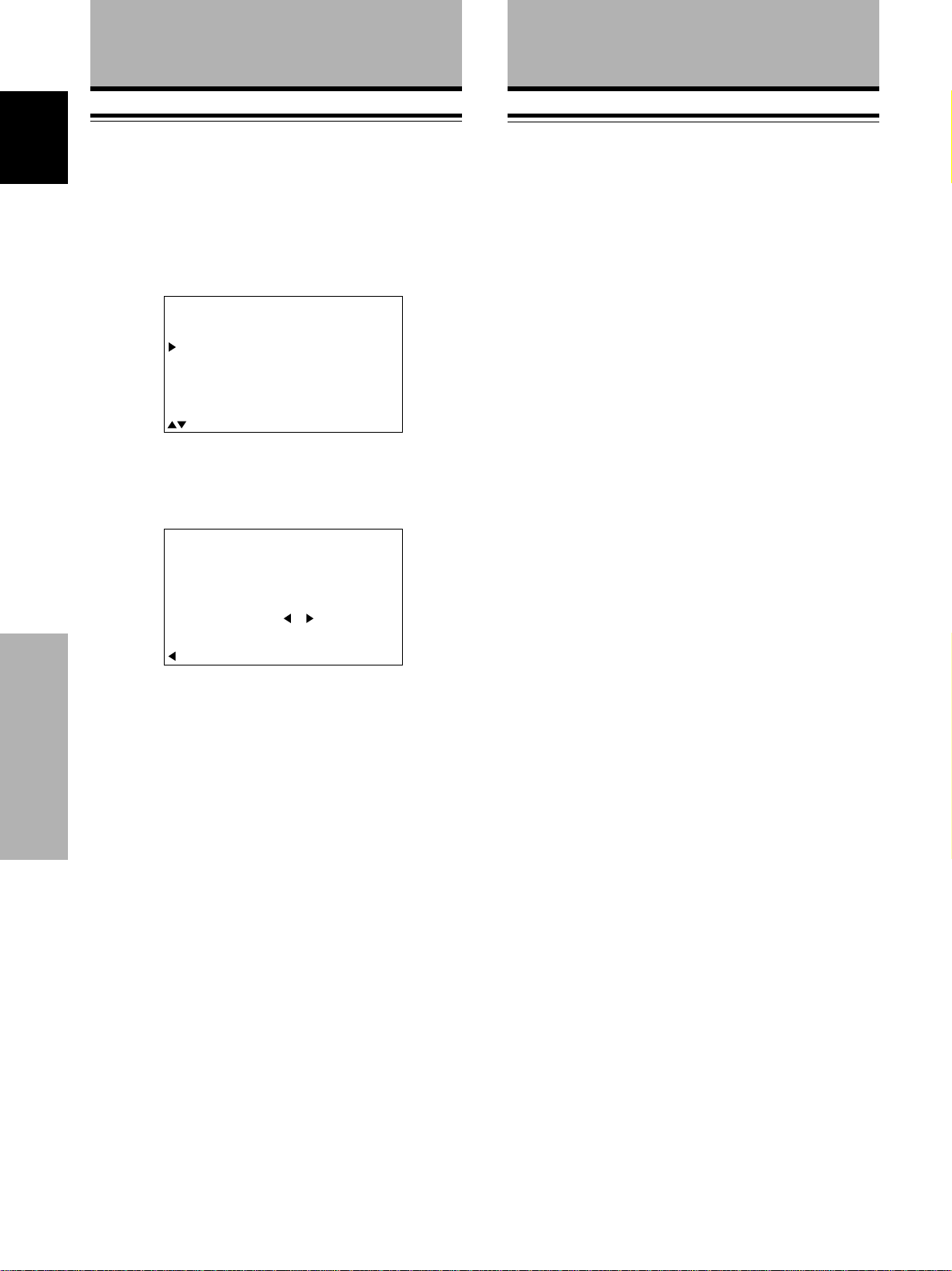
1 Press MENU to display the menu screen.
The menu screen appears.
2 Press 5/∞ to select SET UP, then press SET.
MEN
U
R
N
R
P
U
E
S
E
T
S
AV
E
IN
A
M
P
ICT
S
C
REE
ALLRE
O
WE
P
SETU
Viewing in a bright location
(HIGH CONTRAST)
When viewing a picture in a bright location, setting this
mode to “ON” will enable you to obtain a clear video
image.
• Set this mode to “OFF” when not viewing in a bright
location.
1 Press MENU to display the menu screen.
The menu screen appears.
2 Press 5/∞ to select SET UP, then press SET.
MEN
U
REE
R
:
U
MENU O
:
S
T
R
N
P
EL
N
C
U
E
S
E
S
AV
ECT
NPUT
I
O
NTRA
T
E
F
YSTE
F
S
ET
M
T:OF
S
:
N
:SCA
:AUT
:AUT
X
E
T
RT
O
O
F
IN
A
M
P
ICT
S
C
ALLRE
O
WE
P
SETU
M
EN
3 Press 5/∞ to select HIGH CONTRAST.
SET
TERMI AL
COLGORUPS
SCRA
HIH
English
:
U
M
EN
MENU O
:
S
EL
ECT
F
F
:
ET
X
N
E
T
S
3 Press 5/∞ to select COLOR SYSTEM.
SET
COLGORUPS
SCRA
HIH
EXI
N
TERMI AL
T
I
O
C
T
:S SEEEGNAHC:TLECT
YSTE
NPUT
NTRA
M
T:OF
S
:SCA
:AUT
:AUT
RT
O
O
F
4 Press SET repeatedly until the appropriate setting
appears.
Each time SET is pressed, the settings change in the
following order.
3
AUTO 3 NTSC 3 PAL
4.43 NTSC 2 SECAM 2
5 When the setup is finished, press MENU to exit
the menu screen.
EXI
T
:S SEEEGNAHC:TLECT
When viewing an image from INPUT 3 or INPUT 4,
the following screen is displayed.
SET
TERGMIUPAN
SETT
SINA
CLAM
HIH
GO
EXI
:S SEEEGNAHC:TLECT
I
P
T
L:BNC
NG
L
NTRA
C
:VID
EO
:
CONPOT2EN
M
:MOD
E2
T:OF
S
F
4 Press SET to set the mode to “ON”.
“OFF” is set when this unit is shipped from the
factory. Each time SET is pressed, the settings
change in the following order.
3 ON
OFF 2
5 When the setup is finished, press MENU to exit
the menu screen.
Note
HIGH CONTRAST setting is possible only when selecting the
video input signal from a connected video component.
Display Panel Adjustments
23
<ARE1351> En
Page 28
Display Panel Adjustments
Additional Information
Resetting the monitor to factory set
English
defaults
1 Press MENU to display the menu screen.
The menu screen appears.
2 Press 5/∞ to select ALL RESET, then press SET.
MEN
U
R
R
:
U
MENU O
:
S
E
R
A
U
E
N
S
E
T
S
AV
P
ECT
EL
SE
T
DJUST
Y
E
F
F
:
S
ET
L
ES NO
RELA
X
N
E
T
ET?
S
IN
A
M
P
ICT
S
C
REE
ALLRE
O
WE
P
SETU
M
EN
3 Press 2 to select YES, then press SET.
All settings of the PICTURE and SCREEN modes are
returned to the default settings (factory set defaults).
L
L
A
Troubleshooting
This unit is to be used only when connected to the
plasma display, PDP-502MXE. Should you experience
what seems to be an malfunction, turn the plasma
display’s power off and check the following.
÷ Are connections between this unit and connected
components made correctly ? (Pages 7 to 12)
÷ Are the connector cable connections between this unit
and the plasma display monitor made correctly? (Page 5)
Additionally, check the following sections in the
instructions included with the PDP-502MXE.
÷ Common Problems
÷ Problems commonly mistaken as breakdown
÷ About the self diagnosis mode
If, after checking all the points listed above, the problem
can still not be solved please consult the dealer where
this unit was purchased.
Additional Information
:
S
ECTS
EL
ET:EXI
T
24
<ARE1351> En
Page 29

Specifications
General
External dimensions......... 338 (W) x 156 (H) x 30 (D) mm.
(including monitor)......... 1218 (W) x 737 (H) x 128 (D) mm
Weight...................................................................... 1.1 kg
(including plasma display monitor) ........................ 41.4 kg
Operating temperature range ............................ 0 to 40 °C
Input/output
Video
INPUT1 (BNC)
Input BNC jack
÷ Composite video signal
1 Vp-p/75 Ω/negative sync.
Output BNC jack
75 Ω /with buffer
INPUT 2 (BNC/S)
Input 1 S terminal (Mini DIN 4 pin)
2 BNC jack (x2)
÷ Y/C separate video signal
Y . . . 1 Vp-p/75 Ω/negative sync.
C . . .0.286 Vp-p/75 Ω (NTSC)
0.3 Vp-p/75 Ω (PAL)
Audio
Input INPUT 1
Pin jack (x2)
L/R ... 500mVrms/more than 10 kΩ
INPUT 2
Pin jack (x2)
L/R ... 500mVrms/more than 10 kΩ
Additional Information
INPUT1 (SCART)
Input SCART jack
÷ Composite video signal
1 Vp-p/75 Ω/negative sync.
÷ RGB signal
0.7 Vp-p/75 Ω
÷ Audio L/R. . .500 mVrms/more than 10 kΩ
INPUT2 (SCART)
Input SCART jack
÷ Composite video signal
1 Vp-p/75 Ω/negative sync.
÷ Y/C separate video signal
Y . . . 1 Vp-p/75 Ω/negative sync.
C . . .0.3 Vp-p/75 Ω (PAL)
0.286 Vp-p/75 Ω (NTSC)
÷ Audio L/R. . .500 mVrms/more than 10 kΩ
Output
÷ Composite video signal
1 Vp-p/75 Ω/negative sync.
÷ Audio L/R. . .500 mVrms/less than 1 kΩ
Accessories
Pin/BNC conversion adaptor ............................................ 1
Screw rivets ..................................................................... 8
Connector cover............................................................... 1
Operating Instructions...................................................... 1
÷ Due to improvements, specifications and design are subject to
change without notice.
English
25
<ARE1351> En
Additional Information
Page 30
Additional Information
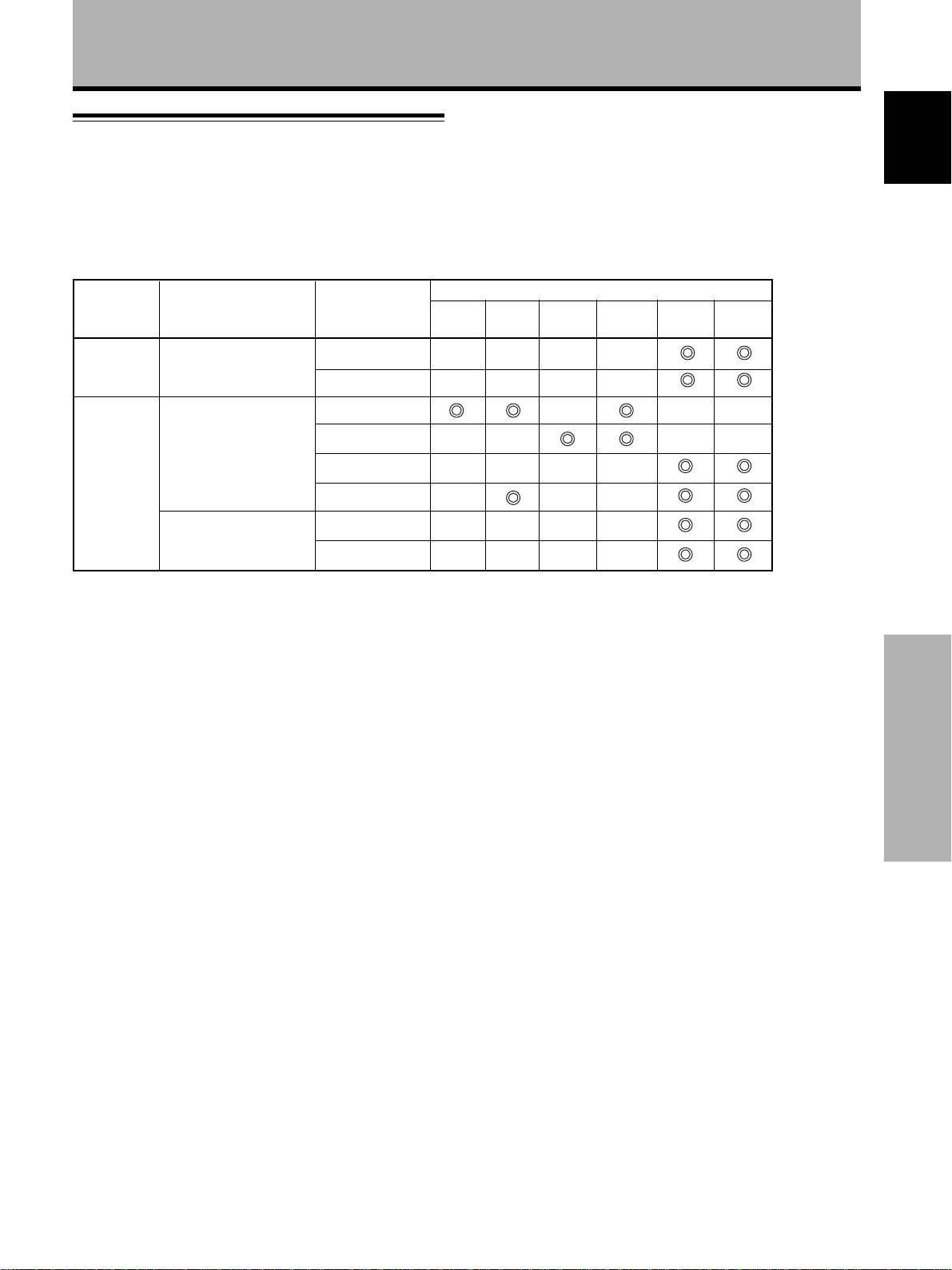
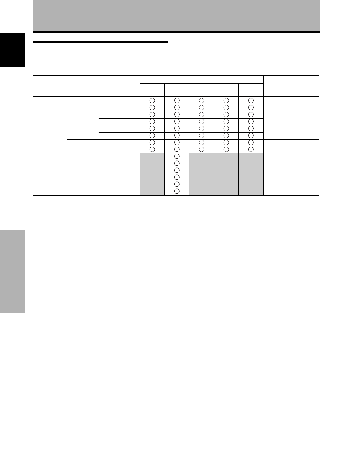
Supplement 1
English
Video signal compatibilty table (INPUT3, INPUT4)
Vertical
frequency
Fv (Hz)
50
60
Horizontal
frequency
Fh (kHz)
15.625
31.25
15.734
31.5
33.75
45.0
67.5
Signal format
Compoment
RGB
Compoment
RGB
Compoment
RGB
Compoment
RGB
Compoment
RGB
Compoment
RGB
Compoment
RGB
4.3
NORMAL
FULL
Screen size
ZOOM
CINEMA
WIDE
NATURAL
WIDE
Remarks
480i (SDTV)
480p (SDTV)
1080i (HDTV)
720p (HDTV)
1080p (HDTV)
Additional Information
26
<ARE1351> En
Page 31

Additional Information
Supplement 2
Assignment of connections for SCART jacks
20 18 16 14 12 10 8 6 4 2
21 19 17 15 13 11 9 7 5 3 1
INPUT1 SCART INPUT2 SCART
1 – 1 Audio output B
2 Audio input B 2 Audio input B
3 – 3 Audio output A
4 Audio ground 4 Audio ground
5 Blue ground 5 –
6 Audio input A 6 Audio input A
7 Blue 7 –
8 Switching voltage 8 Switching voltage
9 Green ground 9 –
10 – 10 –
11 Green 11 –
12 – 12 –
13 Red ground 13 Chroma ground
14 Blanking ground 14 –
15 Red 15 Chroma signal with-S
video
16 Blanking signal 16 –
17 – 17 Video output ground
18 Video input ground 18 Video input ground
19 – 19 Video output
20 Video input 20 Video input or luminance
with-S video
21 Screening or ground 21 Screening or ground
Explanation of Terms
Aspect ratio
The TV screen’s width to height ratio is referred to as its aspect
ratio. The aspect ratio on standard TVs is 4:3 and on wide TVs or
High Definition TVs it is 16:9.
S jack (S VIDEO jack)
This jack separates and transmits the video signal as two signals;
the luminance (Y) signal and the color(C) signal. Because of this,
picture reproduction is superior to that obtained at the composite
input/output jacks.
S-video signal
The video signal is composed of two signals; the chroma signal
(color signal) which reproduces color and the luminance signal
which reproduces light and darkness. With standard video
components, these two signals are combined into one and are
handled as a video signal referred to as the “composite signal”.
The S-video signal, however, is a signal that handles these two
signals separately. Because they are not combined as in the
composite video signal, the high quality of both signals can be
retained.
S1 VIDEO signal/S2 VIDEO signal
This refers to signals that include wide screen picture data such
as squeeze or letterbox data with the color signal (C) that is input
through the S VIDEO jack.
Component video signal
General term for video signal format composed of the Y.CB.CR,
Y.PB.PR and Y.B-Y.R-Y luminance signal + color signal.
The component video signal is sometimes simply called the
“color difference signal”.
G ON SYNC
This indicates a video signal in the form of a synchronization
signal added to the G (GREEN) signal of the RGB signal.
English
Additional Information
Assignment of connections for S-video jack
1342
1 Ground 3 Luminance
2 Ground 4 Chroma signal
Macintosh is a registered trademark of Apple Computer, Inc.
Microsoft is a registered trademark of Microsoft Corporation.
VESA is a registered trademark of Video Electronics
Standards Association.
27
<ARE1351> En
Page 32

Precautions de securite
IMPORTANT
français
Ce symbole de l'éclair, placé dans un triangle
équilatéral, a pour but d'attirer l'attention de
l'utilisateur sur la présence, à l'intérieur du coffret
de l'appareil, de "tensions dangereuses" non isolées
d'une grandeur suffisante pour représenter un risque
d'électrocution pour les êtres humains.
ATTENTION
RISQUE DE CHOC ELECTRIQUE
NE PAS OUVRIR
ATTENTION: Pour éviter tout risque d'électrocution,
ne pas enlever le couvercle (ni le panneau arrière).
Aucune pièce réparable par l'utilisateur ne se trouve
à l'intérieur. Confier tout entretien à un personnel
qualifié uniquement.
Ce point d'exclamation, placé dans un triangle
équilatéral, a pour but d'attirer l'attention de
l'utilisateur sur la présence, dans les documents
qui accompagnent l'appareil, d'explications
importantes du point de vue de l'exploitation ou de
l'entretien.
Nous vous remercions vivement d’avoir fait l’acquisition
de ce produit PIONEER.
Avant d’utiliser cet appareil veuillez lire attentivement les
“Précautions de sécurité” ainsi que le présent “Mode
d’emploi” de manière à utiliser l’écran à plasma
correctement.
Conservez ce manuel dans un endroit sûr. Il vous sera
sûrement utile dans le mois ou les années qui suivent.
ATTENTION: AFIN DE PREVENIR TOUS RISQUES DE
CHOC ELECTRIQUE OU DE DEBUT D’ENCENDIE, NE PAS EXPOSER CET APPAREIL A L’HUMIDITE OU A LA PLUIE.
AVERTISSEMENT:
Il s’agit d’un produit de classe A. Dans un environnement
domestique, ce produit risque de provoquer des
interférences radio; dans ce cas, l’utilisateur est prié
d’engager des mesures adéquates.
Commencer
Pour garantir un rayonnement thermique adéquat, placer l’unité
à une certaine distance des autres équipements, murs, etc.
(normalement à une distance supérieure à 10 cm). Eviter les
modes d’installation décrits ciaprès qui entraînent l’obstruction
des orifices et provoquent une accumulation de chaleur interne,
d’où un risque d’incendie.
• Ne pas essayer de placer l’unité dans des espaces réduirts et
mal ventilés
• Si une installation spéciale est envisagée, comme un montage
à proximité immédiate du mur, un placement horizontal,
consulter d’abord le revendeur Pioneer de votre région.
Remarques sur l’installation:
Ce produit est vendu en assumant qu’il sera installé par un
personnel suffisamment expérimenté et qualifié. Faites toujours
réaliser le montage et l’installation par un spécialiste ou par votre
revendeur.
PIONEER ne peut être tenu responsable pour tout dommage
causé par une erreur d’installation ou de montage, une mauvaise
utilisation ou un désastre naturel.
Remarque pour le revendeur:
Après l’installation, assurez-vous de remettre ce mode d’emploi
à l’utilisateur et de lui expliquer comme utiliser ce produit.
Les symboles qui suivent se trouvent sur les
étiquettes apposées sur le produit. Ils alertent
les utilisateurs de ce matériel ainsi que le
personnel du service aprésvente sur toutes les
situations qui présentent un danger potentiel.
DANGER
Ce symbole concerne un risque ou une
pratique dangereuse qui peut entraîner des
blessures graves ou la mort.
ATTENTION
Ce symbole concerne un risque ou une
pratique dangereuse qui peut entraîner des
blessures ou des dégâts matériels.
ii
i
<ARE1351> Fr
Page 33

Particularités Table des matières
Cet appareil offre davantage de fonctionnalités lorsqu’il
est relié à l’écran à plasma PDP-502MXE. Bien que le
PDP-502MXE soit conçu pour être utilisé comme écran
d’ordinateur, les fonctions et possibilités suivantes
deviennent alors disponibles:
1.Il y a plus de prises d’entrée, ce qui offre des
possibilités de vidéo composite, S vidéo et d’entrée
vidéo luminance/chrominance séparées (INPUT1 et
INPUT2).
2.Le raccordement à plusieurs appareils audiovisuels non
informatiques est possible.
Remarques sur l’installation:
Ce produit est vendu en assumant qu’il sera installé par un
personnel suffisamment expérimenté et qualifié. Faites toujours
réaliser le montage et l’installation par un spécialiste ou par votre
revendeur.
PIONEER ne peut être tenu responsable pour tout dommage
causé par une erreur d’installation ou de montage, une mauvaise
utilisation ou un désastre naturel.
Remarque pour le revendeur:
Après l’installation, assurez-vous de remettre ce mode d’emploi
à l’utilisateur et de lui expliquer comme utiliser ce produit.
Precautions De Securite .................... i
Avant de commencer........................ 2
Comment utiliser ce mode d’emploi................. 2
Description des modes opératoires .................. 2
Vérification des accessoires fournis.................. 2
Les différents organes et leurs
rôles ................................................. 3
Panneau de raccordement
(PDP-502MXE et PDA-5001)............................ 3
Installation et raccordements .......... 5
Connexion de l’appareil à l’écran ...................... 5
A propos des prises d’entrée ............................. 7
Connexion sur INPUT1 ....................................... 8
Connexion sur INPUT2 ....................................... 8
Connexion sur INPUT3 et INPUT4..................... 9
A propos de la connexion du boîtier DVB ...... 11
Raccordements audio....................................... 12
Comment faire cheminer les câbles................ 13
Mise en oeuvre de l’ensemble ....... 14
Réglage des entrées INPUT1 et INPUT2 ......... 14
Réglage des entrées INPUT3 et INPUT4 ......... 15
Mise en oeuvre pour G ON SYNC (CLAMP) ... 16
français
Fonctionnement .............................. 17
Choix de la source ............................................ 17
Choix du format de l’image ............................. 18
ÉCONOMIE D’ÉNERGIE .................................... 20
Réglages de l’écran à plasma......... 21
Réglage de la qualité de l’image ..................... 21
Réglages des caractéristiques de l’image....... 22
Réglage du système de télévision local.......... 23
Visionnement dans une pièce claire (HIGH
CONTRAST) ................................................... 23
Ramener l’écran aux réglages d’usine par
défaut.............................................................. 24
Informations complémentaires ..... 24
Guide de dépannage ........................................ 24
Caractéristiques techniques............................. 25
Supplément 1 .................................................... 26
Supplément 2 .................................................... 27
Glossaire............................................................ 27
Particularités / Table des matières
<ARE1351> Fr
1
Page 34

Avant de commencer
Comment utiliser ce mode d’emploi
Ce mode d’emploi s’organise autour d’explications
classées dans l’ordre qui nous a paru le plus logique à
français
quelqu’un qui prendrait possession de l’écran à plasma
pour la première fois.
Une fois que vous avez déballé l’appareil et que vous avez
bien tous les éléments requis, lisez la section
“Branchement de cet appareil sur l’écran” qui commence
à la page 5 pour plus de détails sur la procédure à suivre
pour brancher cet appareil à l’écran à plasma
PDP-502MXE.
Une fois que l’appareil est branché à l’écran à plasma,
utilisez ce mode d’emploi en même temps que celui du
PDP-502MXE pour commander le système.
Pour vous familiariser avec les éléments, les boutons et
les commandes de cet appareil, avec l’écran à plasma et
avec la télécommande, reportez-vous à la section “Noms
et fonctions des éléments” à la page 3 et à la section
correspondante dans le mode d’emploi du PDP-502MXE.
Une fois que cet appareil est branché à l’écran à plasma
PDP-502MXE, reportez-vous à la section “A propos des
prises d’entrée” qui commence à la page 7 ; celle-ci
donne tous les détails nécessaires pour le branchement à
divers appareils.
La section “Configuration du système”, qui commence à
la page 14, décrit les réglages à effectuer dans l’écran de
menu pour établir correctement le lien avec les appareils
connectés. Selon les connexions, cette section n’est pas
forcément nécessaire.
Avant de commencer
Les sections “Fonctionnement” et “Ajustement de
l’écran d’affichage”, respectivement à partir des pages 17
et 21, sont consacrées aux manipulations de base liées à
la sélection d’un appareil source et aux manipulations plus
complexes liées à l’ajustement de l’image de l’écran à
plasma en fonction des appareils spécifiques et des
préférences personnelles de l’utilisateur.
L’exemple suivant présente une manipulation réelle qui
montre comment on peut régler la luminosité de l’écran.
Les illustrations permettent de vérifier visuellement que
les étapes se déroulent bien comme il convient.
Examinez cet exemple avant de poursuivre la lecture du
mode d’emploi.
1 Appuyez sur la touche MENU pour afficher la page
de menu.
2 Appuyez sur 5/∞ pour sélectionner PICTURE et
appuyez sur 3.
IN
A
M
P
ICT
S
C
REE
ALLRE
O
WE
P
SETU
U
M
EN
U
MEN
U
E
R
N
S
E
S
AV
R
P
:
MENU O
:
S
ECT
EL
:
C
O
NTRAST
B
R
T
GH
I
OL
C
F
T
I
S
HAR
R
ESET
F
OR
NT
P
T
E
0
:
0
:
0
:
0
:
0
3 Appuyez sur 5/∞ pour sélectionner BRIGHT et
appuyez sur SET.
IN
A
M
P
ICT
S
C
REE
ALLRE
O
WE
P
SETU
U
M
EN
U
MEN
U
E
R
N
S
E
S
AV
R
P
:
MENU O
:
S
ECT
EL
:
C
O
NTRAST
B
R
T
GH
I
OL
C
T
E
OR
T
NT
I
S
P
HAR
R
ES
E:T
F
F
S
ADJUST
ET
0
:
0
:
0
:
0
:
0
4 Appuyez sur 2/3 pour ajuster la qualité de
d image selon vos souhaits.
CTU
I
P
BR IGH T
RE
0
S
:EXIT:ADJUST
ET
5 Lorsque vous avez terminé, appuyez sur MENU
pour sortir de l’écran de menu.
Vérification des accessoires fournis
Assurez-vous que les accessoires suivants font partie de
la fourniture.
Description des modes opératoires
Les modes opératoires sont présentés sous la forme
d’étapes numérotées. La plupart sont rédigés en tenant
compte des possibilités de la télécommande, à moins
que la touche ou la commande ne soient présentes que
sur l’écran à plasma. A noter qu’une touche ou une
commande de l’écran à plasma ayant le même nom
qu’une touche ou une commande de la télécommande,
jouent les mêmes rôles.
2
<ARE1351> Fr
1 1 Adaptateur de conversion broches/BNC
2 8 Rivets de fixation
3 1 Cache-prise
÷ Mode d’emploi
Page 35

Les différents organes et leurs rôles
Panneau de raccordement
(PDP-502MXE et PDA-5001)
Pour de plus amples détails concernant les
raccordements, reportez-vous aux pages indiquées entre
parenthèses. D’autres descriptions peuvent être fournies
dans le mode d’emploi de l’écran à plasma PDP-502MXE.
R
SPEAKER
8 Ω – 16 Ω
+–
AUDIO OUTPUT
IN
OUT
COMBINATION
IN
OUT
CONTROL
4 -098765
1 Entrée audio (prises à broches)
Pour obtenir le son lorsque l’entrée INPUT2 (BNC/S) est
sélectionnée. Branchez la prise de sortie audio des appareils
connectés sur l’entrée INPUT2 (BNC/S) sur ces prises (page 12).
2 Entrée audio (prises à broches)
Pour obtenir le son lorsque l’entrée INPUT1 (BNC) est
sélectionnée. Branchez la prise de sortie audio des appareils
connectés sur l’entrée INPUT1 (BNC) sur ces prises (page 12).
INPUT 1INPUT 2
AUDIO
R
AUDIO
R
L
L
1 2 3
RS-232C
(INPUT 4)
R – L
(INPUT 3)
AUDIO INPUT
ANALOG
R G B
INPUT4
7 CONTROL IN/OUT
Utilisez ces prises pour le raccordement de l’écran à
plasma à d’autres appareils PIONEER portant la marque
Î
. Cela fait, cet écran peut être considéré, du point de
vue des commandes, comme faisant partie de l’ensemble.
8 RS-232C
NE BRANCHEZ AUCUN APPAREIL SUR CETTE PRISE.
Cette prise est utilisée pour effectuer des réglages en usine.
VIDEO
OUT
OUTPUT
ANALOG
(
R G B
français
IN
ININ OUTAUDIO 11INAUDIO2
(
3 INPUT1 (BNC)
Pour la connexion d’appareils possédant une prise de
sortie vidéo composite (page 8).
Utilisez la prise INPUT1 OUT pour la sortie du signal
vidéo vers un moniteur externe ou un autre appareil.
Remarque: Le signal vidéo ne sortira pas par la prise
INPUT1 OUT si l’alimentation principale de l’écran à
plasma est coupée ou en veille.
4 Borne SPEAKER (R)
Pour le raccordement à l’enceinte droite. Cette enceinte doit
présenter une impédance comprise entre 8 et 16 Ohms.
5 AUDIO OUTPUT (Mini-prise stéréo)
Pour la sortie audio de l’appareil source sélectionné et
raccordé à cet appareil.
6 COMBINATION IN/OUT
NE BRANCHEZ AUCUN APPAREIL SUR CES
PRISES.
Ces prises sont utilisées pour effectuer des réglages
en usine.
9 AUDIO INPUT (Mini-prise stéréo)
Utilisez cette prise pour disposer des sons appliqués sur INPUT4.
Connectez la prise de sortie audio de l’appareil connecté à
INPUT4 à cette prise (page 12).
0 AUDIO INPUT (Prises Cinch)
Utilisez ces prises pour disposer des sons appliqués
sur INPUT3.
Connectez les prises de sortie audio de l’appareil
connecté à INPUT 3 à ces prises (page 12).
Remarque: La voie gauche (L) n’est pas prévue pour
les sources monophoniques.
- INPUT4
Pour la connexion d’un ordinateur personnel (PC) ou un appareil
similaire. Vérifiez que la connexion effectuée correspond au format
de la sortie du signal provenant de l’appareil connecté (page 9).
Utilisez la prise INPUT4 OUTPUT pour la sortie du signal vidéo vers
un moniteur externe ou un autre appareil.
Remarque: Le signal vidéo ne sortira pas par la prise INPUT4
OUTPUT si l’alimentation principale de l’écran à plasma est coupée
ou en veille.
3
<ARE1351> Fr
Les différents organes et leurs rôles
Page 36

Les différents organes et leurs rôles
français
INPUT 2
S-VIDEOCY
S-VIDEO SCARTSCART2 2 1CY
= ~ ! @
G B R
[ON SYNC] [H/V SYNC]
INPUT3
HD VD
= INPUT2 (BNC/S)
Pour la connexion d’appareils possédant une prise de
sortie S-vidéo ou des prises de sortie vidéo Y/C
séparés (page 8).
Remarque: N’utilisez pas à la fois la prise S-VIDEO et
les prises BNC en parallèle. Cela risque de causer un
dysfonctionnement de l’appareil ou de l’endommager.
Les différents organes et leurs rôles
~ INPUT2 (SCART)
Pour la connexion d’un magnétoscope ou d’un
appareil similaire compatible avec les connexions
SCART (page 8).
! INPUT1 (SCART)
Pour la connexion d’un appareil audio/vidéo
compatible avec les connexions SCART (page 8).
@ Cache-prise pour l’interface vidéo
A retirer pour brancher cet appareil sur l’écran à
plasma PDP-502MXE (page 5).
# INPUT3
Pour la connexion d’appareils possédant une prise de
sortie RVB ou d’appareil tels qu’un ordinateur
personnel, un lecteur de DVD ou un décodeur RVB
extérieur (page 9).
SCART
75Ωj2.2kΩ
$ % ^ &#
INPUT 1
SCART
MAIN POWER
OFF ON
AC INLET
SPEAKER
8 Ω – 16 Ω
+–
L
$ Commutateur de sélection de l’impédance du
signal de synchronisation
Selon les connexions effectuées sur l’entrée INPUT3,
il peut être nécessaire de régler ce commutateur de
façon qu’il corresponde à l’impédance de sortie du
signal de synchronisation de l’appareil connecté.
Quand l’impédance de sortie du signal de
synchronisation de l’appareil est supérieure à
75 Ohms, réglez ce commutateur sur la position
2,2 kOhms (page 10).
% Interrupteur MAIN POWER
Utilisez cet interrupteur pour mettre l’écran à plasma
sous tension ou hors tension.
^ AC INLET
Utilisez cette prise pour connecter un cordon
d’alimentation à une prise secteur.
& Borne SPEAKER (L)
Pour le raccordement à l’enceinte gauche. Cette
enceinte doit présenter une impédance comprise
entre 8 et 16 Ohms.
4
<ARE1351> Fr
Page 37

Installation et raccordements
Connexion de l’appareil à l’écran
Cet appareil ne doit être utilisé que quand il est connecté
à l’écran à plasma PDP-502MXE. Suivez la procédure
décrite dans cette page pour effectuer cette connexion.
Avant de connecter cet appareil à l’écran, n’oubliez
pas d’effectuer les opérations suivantes:
÷ Annulez toute connexion d’appareil ou d’ordinateur
personnel déjà effectuée sur l’écran à plasma.
÷ Assurez-vous que l’écran à plasma est hors tension et
débranché de la prise murale.
Précautions pour connecter l’appareil à l’écran
Lorsque l’appareil et/ou l’écran sont ouverts en vue
d’effectuer les connexions, prenez garde de ne pas faire
tomber les rivets ou autre élément de fixation à l’intérieur.
ATTENTION
Cet appareil est conçu pour être branché uniquement sur l’écran
à plasma PDP-502MXE. Ne le modifiez d’aucune manière que ce
soit, car cela risquerait d’entraîner un mauvais fonctionnement
et/ou de causer un dysfonctionnement de l’écran à plasma.
2 Retirez le volet de protection sur le panneau
arrière de l’écran à plasma.
Les deux connecteurs des câbles sont fixés à
l’intérieur du volet de protection.
français
3 Détachez les deux câbles du volet.
Pour connecter cet appareil à
l’écran à plasma PDP-502MXE
1 Retirez le volet de protection sur le panneau
arrière de l’écran à plasma.
Enlevez les vis à
l’aide d’un
tournevis Philips
(tête “+”).
Remarque
Si pour certaines raisons les vis ne pouvaient pas être dévissées,
utilisez un outil ou un autre objet avec une lame suffisamment
plate pour pénétrer entre la vise et le rivet et pliez la vis comme
montré ci-dessous.
4 Faites passer les deux câbles dans l’orifice du
cache-prise fourni avec cet appareil.
Installation et raccordements
<ARE1351> Fr
5
Page 38

Installation et raccordements
5 Fixez le cache-prise sur l’écran à l’aide de 2 rivets
de fixation (fournis).
1 Séparez la vis du rivet à l’aide d’un tournevis
Philips.
français
2 Insérez le corps des rivets dans les trous prévus à
cet effet sur le volet et dans l’écran à plasma et
placez-les correctement.
3 Enfoncez les vis dans les rivets pour terminer la
fixation.
3
2
6 Retirez le cache de cet appareil.
Lorsque c’est fait, les deux prises de connexion
doivent être parfaitement visibles.
7 Alignez les trous de cet appareil avec les trous
correspondants figurant sur le panneau arrière de
l’écran à plasma et attachez les deux appareils
avec 4 des rivets de fixation fournis.
2
3
1
4
÷ Lors de l’alignement de cet appareil avec l’écran à
plasma, n’oubliez pas de faire passer les deux
câbles de connexion.
÷ Utilisez les rivets de fixation dans l’ordre indiqué ci-
dessus. La procédure de fixation est détaillée dans
l’étape 5.
÷ Lors de la connexion à l’écran à plasma, assurez-
vous que le câble de connexion n’est pas coincé
entre les deux appareils.
Installation et raccordements
6
<ARE1351> Fr
8 Branchez les câbles dans les prises
correspondantes, situées à l’intérieur de l’appareil.
Vérifiez que les connexions sont effectuées
correctement et qu’elles sont fiables.
9 Replacez le cache sur l’appareil.
La connexion de cet appareil est terminée.
Page 39

A propos des prises d’entrée
Branchez les prises de sortie des appareils sur les prises
d’entrée de cet appareil et de l’écran à plasma selon le
tableau ci-dessous (pages 8 à 10).
Prise
Appareils
connectés
et signaux
Appareil audio/vidéo
Vidéo composite
S-vidéo
vidéo Y/C séparé
Appareil
RVB
Ordinateur personnel
(PC)
Vidéo composite
S-vidéo
RVB
d’entrée
INPUT1
(BNC)
*2
INPUT1
(SCART)
INPUT2
(BNC/S)
INPUT2
(SCART)
*2
INPUT3
*1
INPUT4
*3
Installation et raccordements
français
*1
*1 Bien que les entrées INPUT3/INPUT4 soient compatibles
avec différents types de signaux, un réglage à l’écran de
menu est nécessaire une fois que les connexions sont
effectuées de façon à tenir compte des caractéristiques de
l’appareil source (page 15).
*2 Selon la carte de sortie vidéo de l’ordinateur, ce type de
connexion risque de ne pas être possible.
*3 INPUT4 est compatible avec le concept “Plug & Play” de
Microsoft (VESA DDC 1/2B).
Les prises INPUT1 et INPUT2 sont compatibles avec
les systèmes de télévision suivants: NTSC, PAL,
SECAM et 4.43NTSC. Normalement, cet appareil peut
détecter automatiquement le signal pour pallier les
différences entre les systèmes. Toutefois, il est
possible aussi de régler le système. Pour plus de
détails, reportez-vous à “Réglage du système de
télévision local” à la page 23.
Remarque
L’entrée INPUT1 (SCART) RGB n’est pas compatible avec les
signaux G on SYNC.
Installation et raccordements
<ARE1351> Fr
7
Page 40

Installation et raccordements
Connexion sur INPUT1
Connectez un appareil audio/vidéo doté d’une prise de
sortie vidéo sur les prises INPUT1 de cet appareil. Les
français
deux types de connexion suivantes sont disponibles:
÷ Prise BNC
÷ Prise SCART
Une fois que les connexions sont effectuées, une
configuration à l’écran est nécessaire pour définir quelle
prise utiliser (page 14).
Vers un écran distinct
ou un appareil
d’enregistrement vidéo
La prise INPUT1 (SCART) est compatible avec des
signaux audio stéréo (G/D), la vidéo composite et les
signaux vidéo RVB.
La prise INPUT1 (BNC) est compatible avec des signaux
vidéo composites.
La prise INPUT1 OUT (BNC) peut être utilisée pour la
sortie du signal vidéo vers un écran distinct ou un appareil
d’enregistrement vidéo.
Remarque
Aucun signal vidéo ne sortira de la prise OUT [INPUT1] lorsque
l’alimentation principale de cet appareil est coupée ou en veille.
S-VIDEO SCARTSCART2 2 1CYININ OUTAUDIO 11INAUDIO2
Appareil audio/vidéo
Connexion sur INPUT2
Connectez un appareil audio/vidéo doté d’une prise de
sortie vidéo sur les prises INPUT2 de cet appareil.
Les deux types de connexion suivantes sont disponibles:
÷ Prise BNC ou prise S-vidéo (BNC/S)
÷ Prise SCART (pour raccorder un magnétoscope)
Une fois que les connexions sont effectuées, une
Installation et raccordements
configuration à l’écran est nécessaire pour définir quelle
prise utiliser (page 14).
La prise INPUT2 (SCART) est compatible avec des
signaux audio stéréo (G/D), la vidéo composite et les
signaux séparés Y/C.
De plus, un signal audio stéréo et un signal vidéo
composite sortent de la prise INPUT2 (SCART), de sorte
qu’elle convient pour brancher un magnétoscope.
Connectez un appareil audio/vidéo doté de prises de
sortie S-vidéo ou vidéo Y/C séparé sur les prises d’entrée
BNC/S de cet appareil. (La prise INPUT2 S-VIDEO est
compatible avec les signaux de sortie S2.)
Remarque
N’utilisez pas la prise S-VIDEO et les prises BNC en parallèle.
Cela risque de causer un dysfonctionnement de l’appareil ou de
l’endommager.
S-VIDEO SCARTSCART2 2 1CYININ OUTAUDIO 11INAUDIO2
8
<ARE1351> Fr
Magnétoscope
Page 41

Installation et raccordements
Connexion sur INPUT3 et INPUT4
Divers appareils peuvent être connectés sur les prises
IMPUT3 et INPUT4. Une fois que les connexions sont
effectuées, une configuration à l’écran est nécessaire
pour tenir compte des caractéristiques de l’appareil
connecté. Reportez-vous à la page 15 pour plus de détails
sur ces réglages à l’écran.
Prise
INPUT3
[ON SYNC]
GBR
Source en sortie
Appareil vidéo
Ordinateur
personnel (PC
G ON SYNC
B
avec sortie RVB)
B
G
B
Appareil vidéo
avec sortie vidéo
Y
(CB/PB)R(CR/PR)
: Ne rien brancher. : Brancher sur cette prise.
R
RG
[H/V SYNC]
HD VD
H/V SYNC
HD
VD
Connexion aux appareils audio/vidéo
Connexion à un appareil audio/vidéo doté de
prises vidéo en composantes
Effectuez les connexions vidéo en composante pour des
appareils audio/vidéo tels que des lecteurs de DVD ou de LD
ou des appareils similaires à l’aide de la fonction de sortie
vidéo en composante sur les prises RVB INPUT3 ou INPUT4.
Pour le raccordement à INPUT3
G B R HD VD
INPUT3(ON SYNC) (H/V SYNC)
75Ωj2.2kΩ
Y CB/P
C
B
R/PR
français
Remarque
Les appareils compatibles avec INPUT3 sont aussi compatibles
avec INPUT4.
Pour les tailles d’écran et les signaux d’entrée
avec lesquels INPUT3 et INPUT4 sont
compatibles, reportez-vous au Supplément 1
(page 26).
Un réglage général à l’aide des menus affichés sur l’écran est
nécessaire après raccordement. Reportez-vous à la page 15.
Les prises INPUT3 sont toutes des prises BNC.
Si nécessaire, utilisez des adaptateurs de conversion
broches/BNC (1 fourni) pour réaliser des connexions.
Pour le raccordement à INPUT4
ANALOG
R G B
INPUT4
OUTPUT
ANALOG
(
R G B
(
CR/P
B/PB
R
Y
C
Installation et raccordements
Un réglage général à l’aide des menus affichés sur l’écran est
nécessaire après raccordement. Reportez-vous à la page 15.
9
<ARE1351> Fr
Page 42

Installation et raccordements
Connexion d’une source analogique RVB G ON SYNC
Effectuez les connexions G ON SYNC pour un appareil
audio/vidéo avec une sortie qui a un signal de
synchronisation superposé sur le signal vert.
français
Pour le raccordement à INPUT3
G B R HD VD
INPUT3(ON SYNC) (H/V SYNC)
Un réglage général à l’aide des menus affichés sur l’écran est
nécessaire après raccordement. Reportez-vous à la page 15.
Remarques
÷ Lorsque que vous connectez de cette façon, ne connectez rien
à la prise VD ou aux prises HD. Si vous connectez quelque
chose, l’image risque de ne pas être reproduite correctement.
÷ Lorsque vous utilisez un ordinateur connecté via une
connexion G ON SYNC, un réglage à l’écran est nécessaire
(page 16).
Veuillez lire soigneusement le mode d’emploi de l’ordinateur.
Pour le raccordement à INPUT4
Installation et raccordements
ANALOG
R G B
INPUT4
OUTPUT
ANALOG
(
R G B
(
75Ωj2.2kΩ
Connexion d’une source RVB analogique SYNC
composite
Effectuez les connexions SYNC composites pour un
appareil avec une sortie qui possède un signal de
synchronisation verticale superposé au signal de
synchronisation horizontale.
Pour le raccordement à INPUT3
G B R HD VD
INPUT3(ON SYNC) (H/V SYNC)
Si vous utilisez la prise INPUT3, placez le sélecteur
d’impédance de manière à adapter l’appareil à
l’impédance de sortie du signal de synchronisation.
Si l’impédance de sortie du signal de synchronisation est
supérieure à 75 Ohms, placez ce sélecteur sur la position
2,2 kOhms.
Un réglage général à l’aide des menus affichés sur l’écran est
nécessaire après raccordement. Reportez-vous à la page 15.
Remarques
÷ Lorsque que vous connectez de cette façon, ne connectez rien
à la prise VD. Si vous connectez quelque chose, l’image risque
de ne pas être reproduite correctement.
÷ Sur certains types d’ordinateurs Macintosh®, les signaux G ON
SYNC et SYNC composite sont sortis tous les deux. Avec ce
type d’ordinateur, veuillez utiliser la connexion G ON SYNC
(comme ci-contre à gauche).
Pour le raccordement à INPUT4
75Ω j 2.2kΩ
Un réglage général à l’aide des menus affichés sur l’écran est
nécessaire après raccordement. Reportez-vous à la page 15.
10
<ARE1351> Fr
ANALOG
R G B
INPUT4
OUTPUT
ANALOG
(
R G B
(
Un réglage général à l’aide des menus affichés sur l’écran est
nécessaire après raccordement. Reportez-vous à la page 15.
Page 43

A propos de la connexion du boîtier
DVB
Pour assurer une connexion correcte, veuillez lire
attentivement la section “A propos des connexions” du
mode d’emploi du boîtier DVB.
Les signaux de sortie du boîtier avec lesquels cet appareil
est compatible sont les suivants.
Type de signal
HDTV
SDTV
Point x ligne, balayage
(aspect)
1920 x 1080 i (16 : 9)
1920 x 1080 p (16 : 9)
1280 x 720 p (16 : 9)
704 x 480 i (16 : 9)
704 x 480 i (4 : 3)
640 x 480 i (4 : 3)
Format du signal
En composante
RVB
Composite
S-vidéo
En composante
INPUT1
(BNC)
Installation et raccordements
Prises où la connexion est possible
INPUT1
(SCART)
INPUT2
(BNC/S)
INPUT2
(SCART)
français
INPUT4INPUT3
RVB
704 x 480 p (16 : 9)
704 x 480 p (4 : 3)
640 x 480 p (4 : 3)
* L’entrée INPUT1 (SCART) RGB n’est pas compatible avec les
signaux G on SYNC.
En composante
RVB
*
Installation et raccordements
11
<ARE1351> Fr
Page 44

Installation et raccordements
Raccordements audio
Avant d’effectuer des connexions, n’oubliez pas de
vérifier que l’alimentation de l’appareil audio et
l’alimentation principale de l’écran à plasma sont
français
coupées.
Lorsque cet appareil est connecté sur l’écran à plasma
PDP-502MXE, les connexions audio suivantes peuvent
être effectuées.
Les prises et connecteurs suivants se trouvent sur l’écran
à plasma. Pour plus de détails, reportez-vous aux
instructions fournies avec le PDP-502MXE.
÷ connecteurs pour haut-parleur
÷ prise de sortie audio (mini-prise stéréo (G/D))
÷ prises INPUT3 AUDIO INPUT (broches (G/D))
÷ prise INPUT4 AUDIO INPUT (mini-prise stéréo (G/D))
Les prises d’entrée audio suivantes sont disponibles sur
cet appareil:
÷ prises INPUT1 AUDIO INPUT (broches (G/D))
÷ prises INPUT2 AUDIO INPUT (broches (G/D))
Connexion audio pour un appareil connecté sur
INPUT1 ou INPUT2
PDA-5001
Entrée
vidéo
INPUT1
INPUT2
INPUT3
INPUT4
Remarque
La prise d’entrée audio gauche (G) n’est pas compatible avec des
sources d’entrée monaurales.
Prises d’entrée
audio
Cinch (G/D)
Cinch (G/D)
Cinch (G/D)
Mini-fiche stéréo (G/D)
Sortie son
Le son de l’entrée vidéo
sélectionnée sort des prises
SPEAKER.
÷ bornes SPEAKER
÷ les mini-prises stéréo (G/D)
Lorsque des connexions SCART sont effectuées
Lorsque des connexions SCART sont effectuées sur
INPUT1 et/ou INPUT2, le signal audio est entré au niveau
de la prise SCART et il n’est donc pas nécessaire
d’effectuer les connexions audio décrites dans cette
page.
INAUDIO1INAUDIO2
Installation et raccordements
Une fois que les connexions audio et vidéo sont
effectuées, le son correspondant à la source vidéo
sélectionnée sort à la fois des prises AUDIO OUTPUT
(mini-prise stéréo) et des prises SPEAKER de l’écran à
plasma.
12
<ARE1351> Fr
Page 45

Comment faire cheminer les câbles
Des colliers rapides et des serre-câbles sont fournis avec
l’écran pour lier les câbles entre eux. Après raccordements
des appareils, procédez aux opérations qui suivent.
Installation et raccordements
français
* Vue de l’arrière de l’écran.
1
1
2
1 Groupez les câbles en utilisant les colliers rapides
fournis.
Introduisez la partie 1 dans un des perçages à
l’arrière de l’écran à plas ma puis insérez 2 à l’arrière
de 1 pour assurer la fixation.
Les colliers rapides sont conçus pour que l’ouverture
soit difficile. Fermez-les soigneusement.
Fixation des colliers rapides à l’écran à plasma
Engagez les colliers rapides dans les trous 4 repérés par
÷ sur l’illustration ci-dessous.
2
2 Liez les câbles et assurez leur maintien au
moyen des serre-câble fournis.
Remarque
Les câbles peuvent cheminer d’un côté ou de l’autre.
Installation et raccordements
Pour retirer les colliers rapides
A l’aide d’une pince, tordez le collier de 90° puis tirez-le
vers vous. Avec le temps, le collier peut se détériorer et il
peut être nécessaire de la remplacer après que vous
l’avez retiré.
13
<ARE1351> Fr
Page 46

Mise en oeuvre de l’ensemble
Réglage des entrées INPUT1 et
INPUT2
français
Après le raccordement des appareils aux prises INPUT1
ou INPUT2, des réglages à l’aide des menus affichés sur
l’écran sont nécessaires.
÷ Indiquez si les prises BNC ou la prise SCART sont
utilisées pour INPUT1 et INPUT2.
÷ Si la prise SCART est utilisée, choisissez le type de
signal vidéo de manière à ce qu’il corresponde à la
sortie du signal vidéo des appareils connectés.
7 Appuyez sur SET pour sélectionner la prise
d’entrée appropriée.
La prise d’entrée change chaque fois que vous
appuyez sur la touche SET.
Quand l’entrée INPUT1 est sélectionnée
SCART
BNC
Quand l’entrée INPUT2 est sélectionnée
SCART
BNC/S
Procédez aux opérations décrites ci-dessous et effectuez
les réglages en fonction des appareils connectés.
1 Mettez le commutateur MAIN POWER, sur le
panneau de connexion, sur la position “marche”
pour mettre l’écran à plasma sous tension.
Le témoin STANDBY/ON s’éclaire de couleur rouge.
2 Appuyez sur STANDBY/ON pour mettre l’écran
à plasma en état opérationnel.
Le témoin STANDBY/ON s’éclaire de couleur verte.
3 Choisissez INPUT1 ou INPUT2.
4 Appuyez sur la touche MENU pour afficher la page
de menu.
La page de menu s’affiche.
5 Utilisez les touches 5/∞ pour choisir l’option SET
UP puis appuyez sur la touche SET.
IN
A
M
P
ICT
S
C
REE
Mise en oeuvre de l’ensemble
ALLRE
O
WE
P
SETU
U
M
EN
U
MEN
U
E
R
N
S
E
S
AV
R
P
:
MENU O
:
S
ECT
EL
T
E
F
F
:
S
ET
X
N
E
T
8 Appuyez sur 5/∞ pour sélectionner SCART INPUT.
SET
TERMI AL
COLGORUPS
SCRA
HIH
EXI
N
T
I
O
C
T
:S SEEEGNAHC:TLECT
YSTE
NPUT
NTRA
M
T:OF
S
:SCA
:AUT
:AUT
RT
O
O
F
9 Appuyez sur SET pour sélectionner le signal
approprié.
Le signal change chaque fois que vous appuyez sur la
touche SET.
Quand l’entrée INPUT1 est sélectionnée
AUTO
RGB
(Quand AUTO est sélectionné, cet appareil passe
automatiquement en mode RVB quand un signal RVB
arrive.)
Quand l’entrée INPUT2 est sélectionnée
COMPOSITE
Y/C
10 Lorsque le réglage est terminé, appuyez sur
MENU pour sortir de l’écran de menu.
6 Appuyez sur 5/∞ pour sélectionner TERMINAL.
SET
HIH
N
TERMI AL
COLGORUPS
SCRA
T
I
O
C
EXI
T
:S SEEEGNAHC:TLECT
YSTE
NPUT
NTRA
M
T:OF
S
:SCA
:AUT
:AUT
RT
O
O
F
14
<ARE1351> Fr
Remarque
Effectuez ces réglages pour chaque entrée (INPUT1 et INPUT2).
Page 47

Réglage des entrées INPUT3 et INPUT4
Après le raccordement des appareils aux prises INPUT3
ou INPUT4, des réglages à l’aide des menus affichés sur
l’écran sont nécessaires.
Procédez aux opérations décrites ci-dessous et effectuez
les réglages en fonction des appareils connectés.
1 Mettez le commutateur MAIN POWER, sur le
panneau de connexion, sur la position “marche”
pour mettre l’écran sous tension.
Le témoin STANDBY/ON s’éclaire de couleur rouge.
2 Appuyez sur STANDBY/ON pour mettre l’écran
en état opérationnel.
Le témoin STANDBY/ON s’éclaire de couleur verte.
3 Choisissez INPUT3 ou INPUT4.
Mise en oeuvre de l’ensemble
8 Appuyez sur 5/∞ pour sélectionner SIGNAL.
TU
E
S
P
I
T
ERM
A
N
S
SI
C
HH
EX
G
E
N
TTI
G
N
AL
L
AM
P:M
C
I
G
I
T
:
S
ECT
EL
L
NTO
C
:BN
:VIDE
:
R
B
G
O
DE1
R
AS
T
S
ET
O
:
FFO
:
C
A
E
H
NG
9 Appuyez sur SET plusieurs fois de suite pour
sélectionner le format du signal en entrée.
Le format change chaque fois que vous appuyez sur
SET.
RGB
COMPONENT 2
Le tableau ci-dessous indique les réglages appropriés
et disponibles pour le type de connexions effectué.
COMPONENT 1
français
4 Appuyez sur la touche MENU pour afficher la page
de menu.
La page de menu s’affiche.
5 Utilisez les touches 5/∞ pour choisir l’option SET
UP puis appuyez sur la touche SET.
MEN
U
REE
R
:
U
MENU O
:
S
R
N
P
EL
E
S
S
U
E
T
AV
ECT
E
F
F
:
S
ET
X
N
E
T
IN
A
M
P
ICT
S
C
ALLRE
O
WE
P
SETU
M
EN
6 Utilisez les touches 5/∞ pour choisir l’option
SETTING.
TU
E
S
P
I
T
S
SI
C
H
EX
ERM
E
L
A
N
G
N
TTI
G
N
AL
AM
P:M
O
C
I
G
H
I
T
:
S
ECT
EL
L
NT
C
:BN
:VIDE
:
R
B
G
O
D
R
A
S
T
S
ET
O
1
E
:
O
:
C
H
A
E
NFFG
Notez que TERMINAL est réglé sur “BNC” quand
l’entrée INPUT3 est sélectionnée et sur “D-SUB”
quand l’entrée INPUT4 est sélectionnée.
7 Appuyez sur SET pour sélectionner “PC” ou
“VIDEO”.
Quand un ordinateur personnel est connecté, choisissez
“PC”. Pour tout autre appareil, choisissez “VIDEO”.
Remarque
Les opérations 6 à 7 sont nécessaires lorsque le signal d’entrée a une
fréquence de 31,5 kHz (horizontalement) et de 60 Hz (verticalement).
Pour les signaux à d’autres fréquences, les réglages sont effectués
automati quement et ne peuvent donc pas être modifiés.
10 Appuyez sur la touche MENU pour abandonner la
page de menu lorsque la mise en oeuvre est
terminée.
Remarques
÷ Effectuez cette mise en oeuvre pour chaque entrée (INPUT3
ou INPUT4).
÷ quand vous sélectionnez un signal PC ou lorsque SETTING est
réglé sur “PC”, “COMPONENT” ne peut pas être choisi.
÷ Veuillez vous reporter à la page 16 pour plus de détails sur le
réglage CLAMP (G ON SYNC).
Réglez SETTING et SIGNAL comme ci-dessous.
Réglage
Appareil
SETTING
connecté
Sortie vidéo en composante
VIDEO COMPONENT 1*
d’un boîtier DVB
Sortie vidéo en composante
VIDEO
d’un lecteur de DVD, etc
Sortie vidéo RVB d’une
VIDEO
platine vidéo, etc, avec
sortie RVB
Sortie vidéo RVB d’un PC
PC
* Sélectionnez COMPONENT 1 ou 2, selon celui qui offre la
couleur d’image la plus naturelle pour l’appareil connecté.
SIGNAL
COMPONENT 2*
RGB
RGB (fixé sur RVB
quand SETTING est
réglé sur “PC”)
Remarque
Lorsqu’un boîtier DVB est connecté, reportez-vous aussi au
mode d’emploi de ce boîtier.
15
<ARE1351> Fr
Mise en oeuvre de l’ensemble
Page 48

Mise en oeuvre de l’ensemble
Mise en oeuvre pour G ON SYNC
(CLAMP)
En principe, la source RVB fournit 5 signaux séparés: vert,
français
bleu, rouge, synchronisation horizontale et
synchronisation verticale. Si le raccordement est effectué
au moyen de la prise G ON SYNC, 3 signaux seulement
sont disponibles: rouge, vers (synchronisations
horizontale et verticale) et bleu.
Si l’appareil utilisé est un modèle où la connexion G ON
SYNC est utilisée, un réglage à l’écran est nécessaire.
Mise en oeuvre de G ON SYNC (CLAMP)
1 Appuyez sur la touche MENU pour afficher la page
de menu.
La page de menu s’affiche.
2 Utilisez les touches 5/∞ pour choisir l’option SET
UP puis appuyez sur la touche SET.
Remarques
÷ Effectuez la mise en œuvre pour G ON SYNC pour chaque
entrée (INPUT3 ou INPUT4).
÷ Lors de l’utilisation de ce réglage, vérifiez bien la sortie du
signal de l’appareil que vous utilisez. Pour plus de détails,
reportez-vous au mode d’emploi de cet appareil.
÷ Si l’écran devient lumineux et prend une couleur verdâtre,
choisissez la valeur MODE2 pour CLAMP.
÷ Certains ordinateurs Macintosh sont prévus pour un
raccordement de type G ON SYNC.
MEN
U
REE
R
:
U
MENU O
:
S
R
N
P
EL
E
S
S
U
E
T
AV
ECT
E
F
F
:
ET
X
N
E
T
S
IN
A
M
P
ICT
S
C
ALLRE
O
WE
P
SETU
M
EN
3 Utilisez les touches 5/∞ pour choisir l’option
CLAMP.
TU
E
S
Mise en oeuvre de l’ensemble
T
S
SI
C
A
H
V
EX
ERM
E
L
B
.
.
:
P
I
N
N
TTI
G
N
AL
AM
P
L
ENHAN
ENHAN
I
T
S
ECT
EL
L
A
G
CE
CE
:BN
:PC
:
R
:M
:
O
:
:
G
O
F
S
C
B
DE1
F
0
0
ET
:
C
A
H
NG
4 Appuyez sur la touche SET pour choisir MODE2.
Chaque pression sur la touche SET, modifie comme
suit le mode choisi.
3 MODE1 (Raccordement normal)
MODE2 (Raccordement G ON SYNC) 2
E
5 Appuyez sur la touche MENU pour abandonner la
page de menu lorsque la mise en oeuvre est
terminée.
16
<ARE1351> Fr
Page 49

Fonctionnement
Choix de la source
Cette section décrit le fonctionnement de base de cet
appareil quand il est connecté à l’écran. Cette page
explique comment allumer et éteindre l’alimentation
principale de l’écran, mettre l’appareil en mode de
fonctionnement ou de veille et comment sélectionner des
appareils connectés.
Avant tout, assurez-vous que:
÷ Effectué les connexions depuis l’écran et le boîtier
vidéo vers des appareils audio/vidéo et/ou un
ordinateur.
÷ Configuré le menu à l’écran pour recevoir les signaux
des appareils connectés sur les entrées de INPUT1 à
INPUT4 (voir la section “Configuration du système” à la
page 14).
Si aucune connexion n’a été effectuée sur ces
connecteurs, le réglage à l’écran n’est pas nécessaire.
STANDBY/ON
2,5
INPUT
MENU
ADJUST
3
2,5
STANDBY
SCREEN
INPUT
(D-sub)
MENU
SIZE
Y/C
RGB
MUTING
VOL
4
DISPLAY
/ON
VIDEO
12
3
RGB
(BNC)
34
3 Appuyez sur la touche INPUT de la télécommande
ou de l’appareil pour sélectionner l’entrée.
Sur l’écran, l’entrée change chaque fois que vous
appuyez sur INPUT.
3 INPUT23 INPUT1
INPUT4 2 INPUT3 2
÷ L’entrée ne peut pas être modifiée quand un menu
est affiché.
÷ Lorsque la prise SCART est choisie comme entrée
pour INPUT1 et/ou INPUT2 dans les réglages du
système décrits à la page 14, la fonction AUTO de
cet écran peut changer automatiquement d’entrée
quand l’appareil connecté est utilisé.
÷ Quand un signal provient d’un ordinateur, si ce
signal n’est pas compatible avec l’écran, le message
“OUT OF RANGE” s’affiche.
4 Utilisez les touches VOLUME +/– de la
télécommande pour régler le niveau d’écoute.
Si aucune signal sonore n’est appliqué à l’écran à
plasma, cette opération est inutile.
5 Lorsque vous avez fini de regarder les images,
appuyez sur la touche
placer l’écran à plasma en veille.
Le témoin STANDBY/ON clignote puis demeure
éclairé (rouge) indiquant ainsi que l’écran est en veille.
Les commandes ne sont pas reçues quand le témoin
clignote (rouge).
STANDBY/ON pour
français
SET
SIZE
DISPLAY
Panneau de commande
de l’écran à plasma
PDP-502MXE
Télécommande fournie
avec le PDP-502MXE
SET
1 Mettez le commutateur MAIN POWER de l’écran
sur la position “marche” (ON) pour l’allumer.
Le témoin STANDBY/ON s’éclaire de couleur rouge.
2 Appuyez sur STANDBY/ON pour mettre l’écran
en mode de fonctionnement.
Le témoin STANDBY/ON s’éclaire de couleur verte.
6 Mettez le commutateur MAIN POWER de l’écran
sur la position “arrêt” (OFF) pour le mettre hors
tension.
Fonctionnement
PRÉCAUTION
Ne laissez pas la même image affichée sur l’écran pendant une
longue période. Cela peut causer une détérioration de l’écran (on
parle de “brûlage” de l’écran) qui se traduit par la persistence de
cette image atténuée.
17
<ARE1351> Fr
Page 50

Fonctionnement
Choix du format de l’image
Lorsque cet appareil est connecté à l’écran à plasma
PDP-502MXE, il intègre des modes d’écran de divers
français
rapports hauteur/largeur. Pour le visionnement, nous vous
recommandons de choisir le mode d’écran qui convient le
mieux à la source vidéo que vous regardez. Bien que ces
modes soient conçus pour un affichage plein écran sur un
grand écran, nous souhaitons que vous les utilisiez en
comprenant bien les intentions du fabricant.
Choix d’un format d’image
L’image affichée sur l’écran peut avoir un des 5 formats
mentionnés dans le tableau ci-dessous.
Appuyez sur la touche SCREEN SIZE pour
choisir le format.
Chaque pression sur la touche SCREEN SIZE de la
télécommande, ou la touche SIZE de l’écran à plasma,
modifie comme suit le format.
Pour les signaux vidéo
3 NATURAL WIDE 3 4:3 NORMAL
Dans le cas des signaux provenant d’un PC
3 ORIGINAL 3 4:3 NORMAL
FULL 2ZOOM 2
(Pour les tailles d’écran dans le cas où le signal vidéo
provient d’un ordinateur personnel, reportez-vous au
tableau de correspondances des signaux d’entrée de
l’ordinateur dans le mode d’emploi fourni avec le
PDP-502MXE.)
Remarques
÷ Quand le réglage NATURAL WIDE, CINEMA WIDE, ZOOM ou
FULL est utilisé pour afficher une image de petit écran 4:3 sur
un grand écran, une partie de l’image peut être coupée ou
déformée.
÷ Notez que lorsque cet appareil est utilisé pour un
visionnement professionnel ou public et que le mode CINEMA
WIDE ou ZOOM est utilisé pour comprimer ou étirer l’image
affichée, cela peut enfreindre les droits d’auteurs protégés par
la loi des droits d’auteurs.
Changement de la position de
l’image
Quand un film de taille Vista, etc. est visionné avec le
réglage CINEMA WIDE ou ZOOM, l’image peut ne pas
être centrée sur l’écran et dépasser d’un côté de l’écran.
Dans ce cas, ajustez l’écran sur une position clairement
visible en utilisant 5/∞.
Lors d’une entrée en provenance d’un ordinateur
FULL 2ZOOM 2CINEMA WIDE 2
personnel (1280 x 1024/60 Hz uniquement), même en
réglage ZOOM, la position de l’écran peut être ajustée en
utilisant 5/∞.
Fonctionnement
Lors de l’entrée d’un signal vidéo
Aspect de l’image
NATURAL WIDE
4:3 NORMAL
FULL
ZOOM
CINEMA WIDE
Convient pour le visionnement d’émissions d’actualités ou de sport.
Les films ou les émissions sportives peuvent être suivis avec une
image intéressante et puissante.
Convient aux émissions d’actualités ou comédies de situation. Le
logiciel vidéo peut être vu dans sa taille d’écran originale.
(Pour éviter toute brûlure de l’écran de cet appareil, la position
d’affichage est légèrement différente chaque fois que l’appareil
est allumé.)
Convient aux images de grand écran (compressée).
Convient principalement au visionnement de la taille Cinémascope et
à d’autres images de films.
Offre des images plus excitantes et puissantes.
Convient principalement à la taille Vista et à d’autres images de films.
Offre des images plus excitantes et puissantes. Cette taille d’écran
convient au visionnement d’images de taille cinémascope avec des
sous-titres.
18
<ARE1351> Fr
Page 51

Sélection automatique de la taille
de l’écran en fonction du signal
d’entrée
En faisant la distinction entre des signaux tels que les
signaux S1, S2 et HDTV, la taille de l’écran est choisie
automatiquement et les indications suivantes sont
affichées sur l’écran.
Signal d’entrée Fonctionnement Indication sur l’écran
Fonctionnement
français
Quand un signal vidéo S1 est entré
Quand un signal vidéo S2 est entré
Quand un signal HDTV (1920 x 1080i, 1280 x
720p, 1920 x 1080p) est entré
Quand un signal vidéo 16:9 (compressé) arrive au
niveau des prises SCART (Voir le mode d’emploi
de l’appareil audio/vidéo connecté pour déterminer
s’il est compatible avec cette fonction.)
Lors de l’entrée d’un signal d’ordinateur personnel
1 ORIGINAL
Le signal d’entrée et l’image sont dans un rapport point à
ligne de 1/1 et sont donc tout à fait fidèles à la source.
A
640 points
1280 points
(L’illustration concerne une entrée 640 x 480.)
2 4:3 NORMAL
L’image remplit l’écran autant que possible mais le format
n’est pas modifi.
La taille d’écran “FULL” est choisie automatiquement.
La taille d’écran “ZOOM” est choisie automatiquement.
La taille d’écran “FULL” est choisie
automatiquement.
La taille d’écran “FULL” est choisie
automatiquement.
480 lignes
768 lignes
FULL (S1)
ZOOM (S2)
FULL (HD)
FULL (AUTO)
3 FULL
L’image a le format 16/9 et remplit l’écran.
A
4 ZOOM
Le format ZOOM n’est possible que si le signal d’entrée
provient de l’ordinateur (1280 x 1024/60 Hz uniquement).
Le signal d’entrée et l’image sont dans un rapport point à
ligne de 1/1. L’image est tout à fait fidèle à la source.
Toutefois, pour que le rapport 1/1 soit maintenu une partie
de l’image n’est pas affichée.
Fonctionnement
A
768 lignes
1024 lignes
Utilisez les touches 5/∞ pour positionner l’image sur
l’écran.
19
<ARE1351> Fr
Page 52

Fonctionnement
ÉCONOMIE D’ÉNERGIE
Lorsque cet appareil est connecté à l’écran, vous pouvez
utiliser la fonction POWER SAVE pour passer
français
automatiquement en mode de veille si aucun signal vidéo
ou de l’ordinateur n’a été détecté.
(Une indication s’affiche sur l’écran avant le passage en
veille.)
1 Appuyez sur la touche MENU pour afficher la page
de menu.
2 Utilisez les touches 5/∞ pour choisir l’option
POWER SAVE puis appuyez sur la touche SET.
MEN
U
E
R
N
S
S
R
P
:
MENU O
:
S
EL
RSA
O
:
MOD
:
MOD
T
ECT
EL
U
E
T
AV
ECT
VE
E
E1
E
S
F
2
ET
F
:
S
ET
X
N
E
T
:
C
A
E
H
NG
IN
A
M
P
ICT
S
C
REE
ALLRE
O
WE
P
SETU
U
M
EN
3 Appuyez sur 5/∞ pour sélectionner “VIDEO” ou
“PC”.
Sélectionnez “VIDEO” pour définir le mode POWER
SAVE pour l’entrée à partir des sources vidéo ou “PC”
pour définir ce mode pour l’entrée à partir d’un
ordinateur personnel.
WE
O
P
V
IDE
P
C
Fonctionnement
E
XI
:
S
4 Appuyez sur la touche SET pour choisir le mode
d’économie d’énergie.
Lorsque “VIDEO” est sélectionné, le mode POWER
SAVE change de la manière suivante:
3 OFF
MODE1 2
÷ Quand “OFF” est sélectionné, l’écran reste
opérationnel, qu’un signal de synchronisation entre
ou non.
÷ Quand “MODE1” est sélectionné, l’écran passe
automatiquement en mode de veille si aucun
nouveau signal de synchronisation n’entre pendant
8 minutes.
Quand “PC” est sélectionné, le mode POWER SAVE
du PC change de la manière suivante:
3 OFF
MODE2 2 MODE1 2
÷ Quand “OFF” est sélectionné, l’écran reste
opérationnel, qu’un signal de synchronisation entre
ou non.
÷ Quand “MODE1” est sélectionné, l’écran passe
automatiquement en mode de veille si aucun
nouveau signal de synchronisation n’entre pendant
8 minutes.
÷ Quand “MODE 2” est choisi, cet appareil est mis
en mode de veille et d’économie d’énergie si aucun
signal de synchronisation n’est entré. Cependant, si
un signal de synchronisation est entré à nouveau,
cet appareil est remis en service.
5 Appuyez sur la touche MENU pour abandonner la
page de menu dès que les réglages sont terminés.
Remarque
Le réglage POWER SAVE est commun à toutes les entrées
(INPUT1 à INPUT4).
20
<ARE1351> Fr
Pour remettre l’appareil en mode de
fonctionnement
Appuyez sur STANDBY/ON sur l’écran ou la
télécommande.
Si “MODE 2” est choisi pour l’entrée PC, reprendre une
opération sur le PC ou appuyer sur la touche INPUT sur
l’appareil principal ou la télécommande, peut aussi
remettre l’appareil en service.
Page 53

Réglages de l’écran à plasma
Réglage de la qualité de l’image
1 Appuyez sur la touche MENU pour afficher la page
de menu.
2 Utilisez les touches 5/∞ pour choisir l’option
PICTURE puis appuyez sur la touche 3.
IN
A
M
P
ICT
S
C
REE
ALLRE
O
WE
P
SETU
U
M
EN
3 Utilisez les touches 5/∞ pour choisir le paramètre
à régler puis appuyez sur la touche SET.
IN
A
M
P
ICT
S
C
REE
ALLRE
O
WE
P
SETU
U
M
EN
Lors du visionnement d’une image à partir d’un
ordinateur personnel via l’entrée INPUT3 ou INPUT4,
l’écran suivant s’affiche.
U
MEN
U
E
R
N
S
E
S
AV
R
P
:
MENU O
:
S
ECT
EL
U
MEN
U
E
R
N
S
E
S
AV
R
P
:
MENU O
:
S
ECT
EL
:
C
O
NTRAST
B
R
T
GH
I
OL
C
E
F
E
F
OR
T
NT
I
S
HAR
R
ESET
F
C
O
NTRAST
B
R
I
OL
C
OR
T
NT
I
S
HAR
R
ES
F
S
ET
P
T
GH
P
E:T
ADJUST
T
T
0
:
0
:
0
:
0
:
0
:
0
:
0
:
0
:
0
:
0
Paramètres qui peuvent être réglés
Voici de brèves explications sur les paramètres qui
peuvent être réglés grâce à l’option PICTURE.
CONTRAST ············· Réglez le contraste en fonction de
l’éclairage ambiant de manière que
l’image soit bien visible.
BRIGHT ··················· Réglez la luminosité de manière que
les parties sombres de l’image
soient bien visibles.
COLOR···················· Réglez sur la valeur souhaitée. (Un
nombre de couleurs un peu plus
élevé produira une image d’aspect
plus naturel.)
TINT························· Réglez de manière à ce que la
couleur de la peau ait un aspect
normal.
SHARP ···················· Normalement réglé sur la position
centrale. Pour créer une image plus
douce, décalez vers la gauche. Pour
créer une image plus nette, décalez
vers la droite.
R LEVEL ·················· Pour régler la quantité de rouge
dans l’image.
G LEVEL ·················· Pour régler la quantité de vert dans
l’image.
B LEVEL ·················· Pour régler la quantité de bleu dans
l’image.
français
A
IN
M
P
ICT
S
C
REE
ALLRE
O
WE
P
SETU
U
M
EN
U
MEN
U
E
R
N
S
E
S
AV
R
P
:
MENU O
:
S
ECT
EL
:
C
ON
R
ST
A
T
B
RI
H
T
G
R
L
V
L
E
F
G
B
R
ESET
F
S
ET
E
L
V
E
E
L
V
E
E
:ADJUS
L
L
T
E
0
:
0
:
0
:
0
:
0
T
4 Réglez la qualité de l’image à l’aide des touches
2/3.
CTU
I
P
C
ON
RE
AST
R
T
0
S
:EXIT:ADJUST
ET
Appuyer sur SET ramène l’affichage à l’écran de l’étape 3.
5 Appuyez sur la touche MENU pour abandonner la
page de menu lorsque la mise en oeuvre est
terminée.
Remarque
Effectuez ces réglages pour chaque entrée (INPUT1 à INPUT4) et
les signaux.
Pour rétablir les valeurs par défaut des
paramètres de l’option PICTURE
Si les réglages effectués ne vous conviennent pas, il peut
être souhaitable de rétablir les valeurs par défaut des
différents paramètres de l’option PICTURE plutôt que de
continuer à modifier les réglages.
1 Au cours de l’opération 3 ci-dessus, utilisez les
touches 5/∞ pour choisir l’option RESET puis
appuyez sur la touche SET.
CT
I
P
RUE
A
DJUST
Y
:
S
ECTS
EL
E
R
ES NO
ET:EXI
S
ET?
T
2 Appuyez sur la touche 2 pour choisir la valeur
YES puis appuyez sur la touche SET.
Les valeurs par défaut des paramètres de l’option
PICTURE sont rétablies.
Réglages de l’écran à plasma
21
<ARE1351> Fr
Page 54

Réglages de l’écran à plasma
Réglages des caractéristiques de l’image
A régler lorsque l’entrée INPUT3 ou INPUT4 est
sélectionnée.
français
(Les réglages décrits dans cette page ne peuvent pas être
effectués lorsque l’entrée INPUT1 ou INPUT2 est
sélectionnée. “– – –” s’affiche si ce réglage n’est pas
disponible.)
5
Appuyez sur la touche MENU pour abandonner la
page de menu lorsque la mise en oeuvre est terminée.
Remarque
Effectuez ces réglages pour chaque entrée (INPUT3 à INPUT4) et
les signaux.
Paramètres qui peuvent être réglés
Voici de brèves explications sur les paramètres qui
peuvent être réglés grâce à l’option SCREEN.
1
Appuyez sur la touche MENU pour afficher la page de menu.
2
Utilisez les touches 5/∞ pour choisir l’option SCREEN
puis appuyez sur la touch 3.
A
IN
M
P
ICT
S
C
REE
ALLRE
O
WE
P
SETU
U
M
EN
U
MEN
U
E
R
N
S
E
S
AV
R
P
:
MENU O
:
S
ECT
EL
H
.
POSI.
V
.
OS
T
P
.
V
SI
E
C
LK F
C
LK
R
ESET
F
F
I
Z
E
RQ
PHS
:
:
.
:
–––
:
:
3 Utilisez les touches 5/∞ pour choisir le paramètre
à régler puis appuyez sur la touche SET.
A
IN
M
P
ICT
S
C
REE
ALLRE
O
WE
P
SETU
U
M
EN
U
MEN
U
E
R
N
S
E
S
AV
R
P
:
MENU O
:
S
ECT
EL
H
.
POSI.
V
.
OS
T
P
.
V
SI
E
C
LK F
C
LK
R
ESET
F
F
S
:ADJUS
ET
I
Z
E
RQ
PHS
:
:
.
:
:
––
:
––
T
Lors du visionnement d’une image à partir d’un
ordinateur personnel, l’écran suivant s’affiche.
MEN
U
REE
R
:
U
MENU O
:
S
R
N
P
EL
E
S
S
U
E
T
AV
ECT
H
.
POSI.
V
.
OS
P
.
V
SI
E
C
LK F
C
LK
R
ESET
F
F
S
ET
.
I
Z
E
RQ
PHS
:ADJUS
:
:
:
––
:
:
T
A
IN
M
P
ICT
S
Réglages de l’écran à plasma
C
ALLRE
O
WE
P
SETU
M
EN
4 Utilisez les touches 2/3 pour effectuer le réglage.
REE
C
S
N
H.POSITION ············ Réglage de la position latérale de
l’image.
V.POSITION············· Réglage de la position verticale de
l’image.
V.SIZE ······················ Ajuste la hauteur de l’image.
0
0
CLK FREQ. ·············· Réglage des signaux et du bruit. Ce
réglage agit sur la fréquence du
signal de l’horloge interne en
0
0
CLK PHASE ·············
fonction du signal d’entrée vidéo.
Réglage du scintillement et des
erreurs de couleur. Ce réglage agit
sur la phase du signal de l’horloge
interne dont la fréquence a été réglée
au moyen du paramètre CLK FREQ.
Remarques
0
0
0
–
–
÷ Le réglage de V.POSITION n’est pas possible quand la taille de
l’écran est réglée sur ZOOM ou CINEMA WIDE.
Pour régler la position de l’écran vers le haut ou vers le bas,
reportez-vous à la page 18.
÷ Si vous modifiez CLK FREQ., il se peut que vous soyez obligé
de retoucher la valeur de H.POSITION.
÷ Si les paramètres de l’option SCREEN ont des valeurs
excessives, l’image peut être déformée.
Pour rétablir les valeurs par défaut des
paramètres de l’option SCREEN
0
0
–
0
0
Si les réglages effectués ne vous conviennent pas, il peut
être souhaitable de rétablir les valeurs par défaut des
différents paramètres de l’option SCREEN plutôt que de
continuer à modifier les réglages.
1 Au cours de l’opération 3 ci-dessus, utilisez les
touches 5/∞ pour choisir l’option RESET puis
appuyez sur la touche SET.
RE
C
S
NE
H
.P
O
S
ITION
0
S
:EXIT:ADJUST
ET
Utilisez 5/∞ pour les réglages de V.POSITION et
V.SIZE.
Appuyer sur SET ramène l’affichage à l’écran de l’étape 3.
22
<ARE1351> Fr
ET?
A
DJUST
Y
:
S
ECTS
EL
ES NO
E
S
R
ET:EXI
T
2 Appuyez sur la touche 2 pour choisir la valeur
YES puis appuyez sur la touche SET.
Les valeurs par défaut des paramètres de l’option
SCREEN sont rétablies.
Page 55

Réglages de l’écran à plasma
Réglage du système de télévision
local
INPUT1 et INPUT2 sont compatibles avec plusieurs
formats de système de télévision, lesquels sont détectés
automatiquement par cet appareil.
Normalement, “COLOR SYSTEM:AUTO” doit être
sélectionné pour une détection automatique. Cependant,
avec ce réglage, certains signaux vidéo sont doublés ou
dans certaines conditions risquent de ne pas s’afficher
correctement (perte de couleur, etc.) Dans ce cas,
changez de réglage en fonction du signal en entrée.
Remarque
La définition du format du système TV est obligatoire pour les
entrées INPUT1 et INPUT2. Un réglage correct et une utilisation
en fonction du format du système TV de votre signal en entrée
permettront un traitement rapide des signaux et une réduction
du temps requis pour la sélection de l’entrée et des erreurs
éventuelles dans la détection des signaux.
1 Appuyez sur la touche MENU pour afficher la page
de menu.
La page de menu s’affiche.
Visionnement dans une pièce
claire (HIGH CONTRAST)
Lors du visionnement d’une image dans une pièce claire,
régler ce mode sur “ON” permet d’obtenir une image
vidéo nette.
÷ Réglez ce mode sur “OFF” si la pièce n’est pas trop
lumineuse.
1
Appuyez sur la touche MENU pour afficher la page de menu.
La page de menu s’affiche.
2 Utilisez les touches 5/∞ pour choisir l’option SET
UP puis appuyez sur la touche SET.
MEN
U
REE
R
:
U
MENU O
:
S
5/∞
U
E
R
N
S
E
T
S
AV
E
P
F
F
:
EL
ECT
S
ET
X
N
E
T
pour sélectionner HIGH CONTRAST.
3
Appuyez sur
IN
A
M
P
ICT
S
C
ALLRE
O
WE
P
SETU
M
EN
français
2 Utilisez les touches 5/∞ pour choisir l’option SET
UP puis appuyez sur la touche SET.
IN
A
M
P
ICT
S
C
REE
ALLRE
O
WE
P
SETU
U
M
EN
U
MEN
U
E
R
N
S
E
S
AV
R
P
:
MENU O
:
S
ECT
EL
T
E
F
F
:
ET
X
N
E
T
S
3 Appuyez sur 5/∞ pour sélectionner COLOR
SYSTEM.
SET
COLGORUPS
SCRA
HIH
EXI
N
TERMI AL
T
I
O
C
T
:S SEEEGNAHC:TLECT
YSTE
NPUT
NTRA
M
T:OF
S
:SCA
:AUT
:AUT
RT
O
O
F
4 Appuyez plusieurs fois de suite sur SET jusqu’à ce
que le réglage approprié s’affiche.
Chaque pression sur SET affiche un nouveau réglage,
selon l’ordre suivant.
3
AUTO 3 NTSC 3 PAL
4.43 NTSC 2 SECAM 2
5 Appuyez sur la touche MENU pour abandonner la
page de menu dès que les réglages sont terminés.
SET
N
TERMI AL
COLGORUPS
SCRA
T
HIH
EXI
:S SEEEGNAHC:TLECT
I
O
C
T
YSTE
NPUT
NTRA
M
T:OF
S
:SCA
:AUT
:AUT
RT
O
O
F
Lors du visionnement d’une image depuis l’entrée
INPUT3 ou INPUT4, l’écran suivant s’affiche.
SET
TERGMIUPAN
SETT
SINA
CLAM
HIH
GO
EXI
:S SEEEGNAHC:TLECT
4
Utilisez les touche SET pour choisir la valeur “ON”.
I
P
T
L:BNC
NG
L
NTRA
C
:VID
EO
:
CONPOT2EN
M
:MOD
E2
T:OF
S
F
Ce mode est sur “OFF” quand l’appareil sort de
l’usine. Chaque pression sur la touche SET, modifie
comme suit les réglages.
3 ON
OFF 2
5
Appuyez sur la touche MENU pour abandonner la
page de menu lorsque la mise en oeuvre est terminée.
Remarques
Le réglage HIGH CONTRAST est possible uniquement lors de la
sélection du signal d’entrée vidéo à partir d’un appareil vidéo connecté.
Réglages de l’écran à plasma
23
<ARE1351> Fr
Page 56

Réglages de l’écran à plasma
Informations complémentaires
Ramener l’écran aux réglages
d’usine par défaut
français
1 Appuyez sur la touche MENU pour afficher la page
de menu.
Mise en oeuvre de l’ensemble
2 Utilisez les touches 5/∞ pour choisir l’option ALL
RESET puis appuyez sur la touche SET.
MEN
U
R
R
:
U
MENU O
:
S
E
R
N
P
EL
SE
E
S
S
U
E
T
AV
ECT
T
E
F
F
:
S
ET
X
N
E
T
IN
A
M
P
ICT
S
C
REE
ALLRE
O
WE
P
SETU
M
EN
3 Appuyez sur la touche 2 pour choisir la valeur
YES puis appuyez sur la touche SET.
Les valeurs par défaut des paramètres des options
PICTURE et SCREEN sont rétablies (réglages usine).
L
L
A
Guide de dépannage
Cet écran ne doit être utilisé que lorsqu’il est connecté à
l’écran à plasma PDP502MXE. Si vous remarquez
quelque chose qui ressemble à un dysfonctionnement,
éteignez l’écran à plasma et vérifiez les points suivants.
÷ Les connexions entre cet appareil et les autres
appareils ont-elles été effectuées correctement ?
(pages 7 à 12)
÷ Les connexions de câbles entre cet appareil et l’écran à
plasma sont-elles faites correctement ? (page 5)
Reportez-vous également aux sections suivantes du
mode d’emploi du PDP-502MXE.
÷ Problèmes généraux
÷ Problèmes communément confondus avec des pannes
÷ A propos du mode d’auto-diagnostic
Si le problème persiste malgré ces vérifications, veuillez
consulter le revendeur qui vous a fourni l’appareil.
A
:
S
Informations Complémentaires
DJUST
EL
L
Y
ES NO
ECTS
ET?
S
RELA
ET:EXI
T
24
<ARE1351> Fr
Page 57

Caractéristiques techniques
Généralités
Dimensions hors tout.......... 338 (L) x 156 (H) x 30 (P) mm
(avec l’écran) ................... 1218 (L) x 737 (H) x 128 (P) mm
Poids ........................................................................ 1,1 kg
(avec l’écran à plasma)........................................... 41,4 kg
Gamme de température de fonctionnement ....... 0 à 40°C
Entrée/sortie
Vidéo
INPUT1 (BNC)
Entrée prise BNC
÷ signal vidéo composite
1 Vcc/75 Ohms, synchro-négatif
Sortie prise BNC
75 Ohms avec protection
INPUT 2 (BNC/S)
Entrée 1 borne S (mini DIN 4 broches)
2 prise BNC (x 2)
÷ signal vidéo Y/C séparé
luminance . . . 1 Vcc/75 Ohms, synchro-
négative
chrominance . . . 0,286 Vcc/75 Ohms
(NTSC)
0,3 Vcc/75 Ohms (PAL)
Audio
Entrée INPUT 1
Fiche (x 2)
G/D ... 500 mV eff./plus de 10 kOhms
INPUT 2
Fiche (x 2)
G/D ... 500 mV eff./plus de 10 kOhms
Informations complémentaires
INPUT1 (SCART)
Entrée Prise SCART
÷ signal vidéo composite
1 Vcc/75 Ohms, synchro-négatif
÷ signal RVB
0,7 Vcc/75 Ohms
÷ Audio G/D :500 mVrms/plus de
10 kOhms
INPUT2 (SCART)
Entrée Prise SCART
÷ signal vidéo composite
1 Vcc/75 Ohms, synchro-négatif
÷ signal vidéo Y/C séparé
luminance . . . 1 Vcc/75 Ohms, synchro-
négative
chrominance . . . 0,3 Vcc/75 Ohms (PAL)
0,286 Vcc/75 Ohms (NTSC)
÷ Audio G/D . . .500 mVrms/plus de
10 kOhms
Sortie
÷ signal vidéo composite
1 Vcc/75 Ohms, synchro-négatif
÷ Audio G/D . . .500 mVrms/moins de
1 kOhms
Accessoires
Adaptateur de conversion broches/BNC .......................... 1
Rivets de fixation.............................................................. 8
Cache-prise ...................................................................... 1
Mode d’emploi ................................................................. 1
÷ Les caractéristiques et la présentation peuvent être modifiées
sans avis préalable à fin d’amélioration.
français
25
<ARE1351> Fr
Informations Complémentaires
Page 58

Informations complémentaires
Supplément 1
Tableau de compatibilité des signaux vidéo (INPUT3, INPUT4)
français
Fréquence
verticale (Hz)
50
60
Fréquence
horizontale
(kHz)
15.625
31.25
15.734
31.5
33.75
45.0
67.5
Format du signal
En composante
RVB
En composante
RVB
En composante
RVB
En composante
RVB
En composante
RVB
En composante
RVB
En composante
RVB
4.3
NORMAL
Taille de l’écran
FULL
ZOOM
CINEMA
WIDE
NATURAL
WIDE
Remarques
480i (SDTV)
480p (SDTV)
1080i (HDTV)
720p (HDTV)
1080p (HDTV)
Informations Complémentaires
26
<ARE1351> Fr
Page 59

Informations complémentaires
Supplément 2
Affectation des connexions pour les prises
SCART
20 18 16 14 12 10 8 6 4 2
21 19 17 15 13 11 9 7 5 3 1
INPUT1 SCART INPUT2 SCART
1 – 1 Sortie audio B
2 Entrée audio B 2 Entrée audio B
3 – 3 Sortie audio A
4 Masse audio 4 Masse audio
5 Masse du bleu 5 –
6 Entrée audio A 6 Entrée audio A
7 Bleu 7 –
8 Changement de tension 8 Changement de tension
9 Masse du vert 9 –
10 – 10 –
11 Vert 11 –
12 – 12 –
13 Masse du rouge 13 Masse de chrominance
14 Masse de suppression 14 –
15 Rouge 15 Signal de chrominance
avec S-vidéo
16 Signal de suppression 16 –
17 – 17 Masse de sortie vidéo
18 Masse d’entrée vidéo 18 Masse d’entrée vidéo
19 – 19 Sortie vidéo
20 Entrée vidéo 20 Entrée vidéo ou
luminance avec S-vidéo
21 Blindage ou masse 21 Blindage ou masse
Glossaire
Format d’image
Le rapport de la largeur à la hauteur de l’image donne son format.
Dans le cas d’un téléviseur standard, ce format est égale à 4/3;
dans le cas de la télévision haute définition il est égale à 16/9.
Prise S (prise S-vidéo)
Cette prise se scinde en deux et transmet le signal vidéo sous la
forme de deux signaux, le signal de luminance (Y) et le signal de
chrominance (C). La reproduction de l’image est alors supérieure
à celle obtenue via les prises d’entrée/sortie composites.
Signal S-vidéo
Le signal vidéo se compose de deux signaux : le signal de
chrominance (couleur) qui reproduit la couleur et le signal de
luminance qui reproduit la lumière et les ombres. Avec des
appareils vidéo standard, ces deux signaux sont combinés en un
seul et traités comme un signal vidéo dit “signal composite”. Le
signal S-vidéo cependant est un signal qui gère ces deux signaux
séparément. Comme ils ne sont pas combinés comme dans le
signal vidéo composite, la qualité optimale de ces deux signaux
peut être préservée.
Signal vidéo S1/S2
Il s’agit des signaux qui incluent des données d’image en grand
écran, comme “Ecrasé” et “Letterbox”, avec le signal de
chrominance (C) qui est entré via la prise S-vidéo.
Signal vidéo en composante
Terme générique pour le format de signal vidéo composé du
signal de luminance Y.CB, CR, Y.PB, PR et Y.B-Y.R + le signal de
chrominance.
On l’appelle parfois simplement “signal en couleurs séparées”.
G ON SYNC
La synchronisation du signal RVB est obtenue par l’addition d’un
signal de synchronisation au signal du vert (G).
français
Informations Complémentaires
Affectation des connexions pour la prise S-vidéo
1342
1 Masse 3 Luminance
2 Masse 4 Signal de chrominance
Macintosh est une marque déposée par Apple Computer Inc.
Microsoft est une marque déposée par Microsoft Corporation.
VESA est une marque déposée par Video Electronics
Standards Association.
27
<ARE1351> Fr
Page 60

Sicherheitsmassnahmens
IMPORTANT
The lightning flash with arrowhead symbol, within
an equilateral triangle, is intended to alert the user to
the presence of uninsulated “dangerous voltage”
within the product’s enclosure that may be of
Deutsch
sufficient magnitude to constitute a risk of electric
shock to persons.
CAUTION
RISK OF ELECTRIC SHOCK
DO NOT OPEN
CAUTION:
TO PREVENT THE RISK OF ELECTRIC
SHOCK, DO NOT REMOVE COVER (OR
BACK). NO USER-SERVICEABLE PARTS
INSIDE. REFER SERVICING TO QUALIFIED
SERVICE PERSONNEL.
The exclamation point within an equilateral triangle
is intended to alert the user to the presence of
important operating and maintenance (servicing)
instructions in the literature accompanying the
appliance.
Herzlichen Dank, daß Sie sich für den Kauf dieses
PIONEER-Produktes entschieden haben.
Bevor Sie dieses Gerät benutzen, lesen Sie bitte
sorgfältig den Abschnitt “Sicherheitsmaßnahmen” und
diese Bedienungsanleitung durch, um eine problemlose
Verwendung des Plasma-Displays zu gewährleisten.
Bewahren Sie diese Anleitung an einem sicheren Ort auf.
Sie wird Ihnen in Zukunft nützliche Dienste leisten.
WARNUNG: ZUR VERMEIDUNG VON BRAND ODER
STROMSCHLAG DARF DIESES GERÄT WEDER REGEN noch
FEUCHTIGKEIT AUSGESETZT WERDEN.
WARNUNG:
Dies ist ein Produkt der Warenklasse A. In Wohngegenden
kann dieses Produkt zu Funkstörungen führen. In diesem Fall
müssen die entsprechenden Maßnahmen getroffen werden.
WARNUNG:
Dieses produkt entspricht dem EMV-Standard der Klasse A.
Produkte dieser Klasse sind nur für den industriellen Einsatz
geeignet und dürfen in Wohnund Gewerbegebieten nicht
ohne ausreichende Entstörungsmaßnahmen betrieben
Vorwort
werden.
Die nachstehenden Symbole befinden sich auf
dem Gerät angebrachten Aufklebern. Sie machen
den Benutzer und das Wartungspersonal auf
mögliche Gefahren aufmerksam.
WARNUNG
Dieses Symbol weist auf eine gefährliche
oder unsichere Handlung hin, die zu
schweren Personenschäden oder T od führen
kann.
VORSICHT
Dieses Symbol weist auf eine gefährliche
oder unsichere Handlung hin, die zu
Personenoder Sachschäden führen kann.
Um eine ausreichende Lüftung zu gewährleisten, sollte das Gerät
im Mindestabstand von etwas mehr als 10 cm von anderen Geräten,
Wänden usw. aufgestellt werden. V ermeiden Sie die nachstehenden
Installationsarten, die die Ventilationsschlitze blockieren könneten.
Dadurch könnte im inneren des Gerätes ein Wärmestau entstehen,
der wiederum Feuer auslösen könnte.
÷ Stellen Sie das Gerät nicht in engen Räumen mit unzureichender
Lüftung auf.
÷ Stellen Sie das Gerät nicht auf den Kopf. Wenn Sie eine spezielle
Installation beabsichtigen, z.B. unmittelbar an einer Wand, in
horizontaler Position usw., lassen Sie sich vorher von lhrem Pioneer Fachhändler beraten.
ii
i
<ARE1351> Ge
Page 61

Merkmale Inhaltsverzeichnis
Dieses Gerät bietet zusätzliche Vorzüge, wenn es mit
dem Plasma-Display PDP-502MXE verbunden wird.
Modell PDP-502MXE ist zur Verwendung als Monitor in
Verbindung mit einem Personal-Computer bestimmt; bei
Anschluß dieses Geräts sind zusätzlich die nachfolgenden
Funktionen und Bedienungsvorgänge möglich.
1.Die Anzahl der Eingangsanschlüsse wurde erhöht: es
stehen nun Anschlüsse für ein zusammengesetztes
Videosignal, S-Videosignal und getrennte
Eingangsbuchsen für Y/C-Videosignale (INPUT1 und
INPUT2) zur Verfügung.
2.Eine Verbindung mit einer begrenzten Zahl von Audio-
Video-Komponenten, die nicht mit dem PC im
Zusammenhang stehen, ist ebenfalls möglich.
Hinweise zur Installation:
Dieses Produkt wird unter der Annahme vertrieben, daß es von
einem qualifizierten Techniker installiert wird, der über die
erforderlichen technischen Kenntnisse und Erfahrung für diese
Arbeiten verfügt. Zur Installation und dem Setup dieses Geräts
ist daher stets ein damit vertrauter Kundendiensttechniker oder
der Verkaufshändler zur Rate zu ziehen. PIONEER übernimmt
keine Haftung für Schäden, die durch Fehler bei der Installation
bzw. der Befestigung, durch unsachgemäße Verwendung,
Modifikation sowie durch Naturkatastrophen entstanden sind.
Sicherheitsmassnahmens ................. i
Vor der Inbetriebnahme ................... 2
Verwendung dieser Anleitung ........................... 2
Hinweise zu den Bedienungsschritten dieser
Anleitung.......................................................... 2
Überprüfen der mitgelieferten Zubehörteile .... 2
Bezeichnung der Teile und
Funktionen ...................................... 3
Anschlußleiste (PDP-502MXE und PDA-5001).. 3
Aufstellung und Anschlüsse ............ 5
Anschluß dieses Geräts am Monitor................. 5
Hinweise zu den Eingangsbuchsen................... 7
Anschluß an INPUT1 .......................................... 8
Anschluß an INPUT2 .......................................... 8
Anschluß an INPUT3 und INPUT4..................... 9
Hinweise zum Anschluß der DVB-Top Box..... 11
Audio-Anschlüsse ............................................. 12
Verlegung der Kabel ......................................... 13
System-Setup.................................. 14
Einstellen von INPUT1 und INPUT2 ................ 14
Einstellen von INPUT3 und INPUT4 ................ 15
Setup für G ON SYNC (CLAMP)....................... 16
Deutsch
Hinweis für den Händler:
Nach der Installation diese Anleitung dem Kunden aushändigen
und die Verwendung des Produkts erläutern.
Bedienungsschritte ......................... 17
Wahl einer Eingangssignalquelle .................... 17
Wahl des Bildschirmformats............................ 18
ENERGIESPARFUNKTION
(POWER SA VE) .............................................. 20
Einstellung des Displays................. 21
Einstellen der Bildqualität ................................ 21
AEinstellen der Abbildung am Display ........... 22
Einstellen auf das örtliche Fernsehsystem ..... 23
Betrachten in einer hellen Umgebung
(HIGH CONTRAST) ........................................ 23
Rückstellen des Monitors auf die werkseitigen
Voreingabewerte ........................................... 24
Zusätzliche Informationen ............. 24
Störungssuche .................................................. 24
Technische Daten .............................................. 25
Nachtrag 1 ......................................................... 26
Nachtrag 2 ......................................................... 27
Erläuterung der Begriffe................................... 27
Merkmale / Inhaltsverzeichnis
1
<ARE1351> Ge
Page 62

Vor der Inbetriebnahme
Verwendung dieser Anleitung
Die in dieser Anleitung enthaltenen Hinweise sind in einer
Reihenfolge angeordnet, die der logischen Vorgehensweise beim
Aufstellen und der Inbetriebnahme dieses Geräts entspricht.
Nachdem das Display aus dem Versandkarton genommen und alle
mitgelieferten Teile auf Vollständigkeit überprüft wurden, sind die
Deutsch
Anweisungen im Abschnitt “Anschluß dieses Geräts am den
Monitor”, beginnend auf Seite 5; an dieser Stelle wird die
Vorgehensweise zum Anschluß dieses Geräts an das Plasma-Display
PDP-502MXE erläutert.
Nachdem das Gerät mit dem Plasma-Display verbunden wurde, ist
diese Anleitung in Verbindung mit der Bedienungsanleitung des PDP502MXE zur Steuerung des Systems zu verwenden.
Es wird empfohlen, den Abschnitt “Bezeichnung der Teile und
Funktionen” auf Seite 3 und der entsprechenden Kapitel der
Bedienungsanleitung des PDP-502MXE durchzulesen, um sich mit
den Tasten und Bedienungselementen dieses Geräts, des PlasmaDisplays und der Fernbedienungseinheit vertraut zu machen.
Nachdem dieses Gerät am Plasma-Display PDP-502MXE
angeschlossen wurde, den Abschnitt “Hinweise zu den
Eingangsbuchsen” auf Seite 7 durchlesen; dieses Kapitel enthält alle
notwendigen Hinweise in bezug auf die Anschlüsse an einer Vielzahl
von verschiedenen Komponenten.
Das auf Seite 14 beginnende Kapitel “Syetem-Setup” erläutert die
erforderlichen Einstellungen für die On-Screen-Menüs, um eine
korrekte Verbindung zwischen dem Plasma-Display und den
angeschlossenen Komponenten herzustellen. Abhängig von den
vorgenommenen Anschlüssen kann dieses Kapitel unter Umständen
übergangen werden.
Vor der Inbetriebnahme
Die Kapitel “Bedienungsschritte” und “Einstellung des Displays” auf
den Seiten 17 bzw. 21 enthalten grundlegende Bedienungsschritte
zur Wahl einer Quellenkomponente, sowie weiterführende
Bedienungsvorgänge, wie zum Beispiel Bildeinstellungen für das
Plasma-Display, um den Anforderungen spezifischer Komponenten
und der persönlichen Vorliebe zu entsprechen.
Das nachfolgende Beispiel zeigt die erforderlichen Bedienungsschritte
zur Einstellung der Bildschirmhelligkeit. Die nach jedem Schritt
angezeigten Menüs dienen als visuelle Benutzerführung, um
sicherzustellen, daß jede Eingabe korrekt vorgenommen wurde. Bitte
machen Sie sich mit dieser Vorgehensweise vertraut, bevor die
weiteren Abschnitte dieser Bedienungsanleitung durchgelesen werden.
1
MENU drücken, um den Menübildschirm aufzurufen.
2 Die 5/∞-Taste drücken, um PICTURE zu wählen,
dann die 3-Taste drücken.
IN
A
M
P
ICT
S
C
REE
ALLRE
O
WE
P
SETU
U
M
EN
U
MEN
U
E
R
N
S
E
S
AV
R
P
:
MENU O
:
S
ECT
EL
:
C
O
NTRAST
B
R
T
GH
I
OL
C
F
T
I
S
HAR
R
ESET
F
OR
NT
P
T
E
0
:
0
:
0
:
0
:
0
3 Die 5/∞-Taste drücken, um BRIGHT zu wählen,
dann SET drücken.
IN
A
M
P
ICT
S
C
REE
ALLRE
O
WE
P
SETU
U
M
EN
U
MEN
U
E
R
N
S
E
S
AV
R
P
:
MENU O
:
S
ECT
EL
:
C
O
NTRAST
B
R
T
GH
I
OL
C
T
E
OR
T
NT
I
S
P
HAR
R
ES
E:T
F
F
S
ADJUST
ET
0
:
0
:
0
:
0
:
0
4 Die 2/3-Taste drücken, um die Bildqualität wie
gewünscht einzustellen.
CTU
I
P
BR IGH T
RE
0
S
:EXIT:ADJUST
ET
5 Nachdem das Setup beendet ist, die MENU-Taste
drücken, um den Menübildschirm zu verlassen.
Überprüfen der mitgelieferten Zubehörteile
Sich vergewissern, daß die nachstehend aufgeführten
Zubehörteile vorhanden sind.
Hinweise zu den Bedienungsschritten
1 Stiftstecker-/BNC-Adapter x 1
dieser Anleitung
Die in dieser Anleitung auszuführenden Bedienungsschritte werden in
numerischer Folge aufgeführt. Die überwiegende Anzahl der
angegebenen Schritte beziehen sich auf die Fernbedienungseinheit - es
sei denn, die betreffende Taste oder der Regler ist nur am Hauptgerät
vorhanden. Wenn die Taste bzw. der Regler des Hauptgeräts allerdings
die gleiche oder eine ähnliche Bezeichnung wie das Bedienungselement
der Fernbedienungseinheit aufweist, kann diese Taste ebenfalls zur
Eingabe des betreffenden Bedienungsschritts verwendet werden.
2
<ARE1351> Ge
2 Schraubklammer x 8
3 Steckerabdeckung x 1
÷ Bedienungsanleitung
Page 63

Bezeichnung der Teile und Funktionen
Anschlußleiste
(PDP-502MXE und PDA-5001)
Für weitere Einzelheiten in bezug auf einen spezifischen
Anschluß sich auf die in Klammern angegebene
Referenzseite beziehen. Weitere Einzelheiten sind in der
Bedienungsanleitung enthalten, die beim Plasma-Display
PDP-502MXE mitgeliefert wurde.
INPUT 1INPUT 2
AUDIO
R
AUDIO
R
L
OUT
L
1 2 3
VIDEO
IN
ININ OUTAUDIO 11INAUDIO2
Deutsch
R
SPEAKER
8 Ω – 16 Ω
+–
AUDIO OUTPUT
IN
OUT
COMBINATION
IN
OUT
CONTROL
4 -098765
1
AUDIO INPUT (Stiftbuchse) (Audio-Eingangsanschluß)
An dieser Buchse liegt das Audiosignal an, wenn INPUT2
(BNC/S) gewählt wurde. Die Audio-Ausgangsbuchse der
an INPUT2 (BNC/S) angeschlossenen Komponenten mit
diesen Buchsen verbinden (Seite 12).
2
AUDIO INPUT (Stiftbuchse) (Audio-Eingangsanschluß)
An dieser Buchse liegt das Audiosignal an, wenn INPUT1
(BNC) gewählt wurde. Die Audio-Ausgangsbuchse der an
INPUT1 (BNC) angeschlossenen Komponenten mit
diesen Buchsen verbinden (Seite 12).
3 INPUT1 (BNC) (Eingangsanschluß)
Zum Anschluß von Komponenten, die über einen
Ausgangsanschluß für ein zusammengesetztes
Videosignal verfügen (Seite 8).
Den Anschluß INPUT1 OUT zur Ausgabe des Videosignals
zu einem externen Monitor oder einer anderen
Komponente verwenden.
Hinweis: Das Videosignal wird nicht über den
Anschluß INPUT1 OUT abgegeben, wenn die
Stromversorgung zum Hauptgerät ausgeschaltet ist
oder sich das Gerät im Bereitschaftsmodus befindet.
4 SPEAKER (R) (Lautsprecherklemme rechts)
Zum Anschluß des externen rechten Lautsprechers.
Einen Lautsprecher anschließen, der über eine
Impedanz von 8 - 16 Ohm verfügt.
5 AUDIO OUTPUT (Stereo-Minibuchse) (Audio-
Ausgangsanschluß)
Zur Ausgabe des Audiosignals der gewählten
Signalquelle, die mit diesem Gerät verbunden ist.
6 COMBINATION IN/OUT (Kombi-Eingangs-/
Ausgangsanschlüsse)
KEINE ANSCHLÜSSE AN DIESEN BUCHSEN VORNEHMEN.
Diese Anschlüsse werden für das werkseitige Setup
verwendet.
RS-232C
7
CONTROL IN/OUT (Steuerkabel-Anschlüsse Ein/Aus)
(INPUT 4)
R – L
(INPUT 3)
AUDIO INPUT
ANALOG
R G B
INPUT4
OUTPUT
ANALOG
(
R G B
Zum Anschluß von PIONEER-Komponenten, die mit
dem Î-Symbol versehen sind. Durch einen Anschluß
über die CONTROL-Buchse kann dieses Gerät als
Systemkomponente gesteuert werden.
8 RS-232C (RS232C-Schnittstelle)
KEINE ANSCHLÜSSE AN DIESER BUCHSE VORNEHMEN.
Dieser Anschluß wird für das werkseitige Setup verwendet.
9
AUDIO INPUT (Stereo-Minibuchse) (Audio-Eingangsanschluß)
Diese Buchse dient zur Eingabe des an INPUT4 anliegenden
Eingangssignals. Den Audio-Ausgangsanschluß der mit
INPUT4 verbundenen Komponenten an dieser
Eingangsbuchse anschließen (Seite 12).
0
AUDIO INPUT (Stiftbuchse) (Audio-Eingangsanschluß)
Diese Buchse dient zur Eingabe des an INPUT3 anliegenden
Eingangssignals. Den Audio-Ausgangsanschluß der mit
INPUT3 verbundenen Komponenten an dieser
Eingangsbuchse anschließen (Seite 12).
Hinweis: Die Buchse für den linken Audiokanal (L) ist
mit monauralen Eingangssignalquellen nicht
kompatibel.
- INPUT4 (Eingangsanschluß)
Zum Anschluß eines Personal-Computers (PC) oder
einer ähnlichen Komponente. Sich vergewissern, daß
der vorgenommene Anschluß mit dem SignalausgabeFormat der angeschlossenen Komponente
übereinstimmt (Seite 9). Den Anschluß INPUT4
OUTPUT zur Ausgabe des Videosignals zu einem
externen Monitor oder einer anderen Komponente
verwenden.
Hinweis: Das Videosignal wird nicht über den
Anschluß INPUT4 OUTPUT abgegeben, wenn die
Stromversorgung zum Hauptgerät ausgeschaltet ist
oder sich das Gerät im Bereitschaftsmodus befindet.
(
und Funktionen
Bezeichnung der Teile
3
<ARE1351> Ge
Page 64

Bezeichnung der Teile und Funktionen
Deutsch
und Funktionen
Bezeichnung der Teile
INPUT 2
S-VIDEOCY
S-VIDEO SCARTSCART2 2 1CY
SCART
= ~ ! @
G B R
[ON SYNC] [H/V SYNC]
INPUT3
HD VD
75Ωj2.2kΩ
$ % ^ &#
= INPUT2 (BNC/S) (Eingangsanschluß)
Zum Anschluß von Komponenten, die über eine SVideo-Ausgangsbuchse oder getrennte Y/C-VideoAusgangsbuchsen verfügen (Seite 8).
Hinweis: Die Buchsen für S-VIDEO und BNC dürfen
nicht gleichzeitig verwendet werden. Wenn dies nicht
beachtet wird, kann eine Funktionsstörung oder sogar
eine Beschädigung des Geräts die Folge sein.
~ INPUT2 (SCART) (Eingangsanschluß)
Zum Anschluß eines VCR oder einer ähnlichen
Komponente, die mit SCART-Anschlußbuchsen
kompatibel ist (Seite 8).
! INPUT1 (SCART) (Eingangsanschluß)
Zum Anschluß einer AV-Komponente, die mit SCARTAnschlußbuchsen kompatibel ist (Seite 8).
@ Anschlußabdeckung für Videobox
Diese Abdeckung abnehmen, wenn dieses Gerät mit
dem Plasma-Display PDP-502MXE verbunden werden
soll (Seite 5).
# INPUT3 (Eingangsanschluß)
Zum Anschluß von Komponenten, die über
Ausgangsanschlüsse für RGB-Signale oder
zusammengesetzte Signale verfügen, wie zum
Beispiel einem Personal-Computer, DVD-Spieler oder
einem externen RGB-Dekoder (Seite 9).
4
<ARE1351> Ge
INPUT 1
SCART
MAIN POWER
OFF ON
AC INLET
SPEAKER
8 Ω – 16 Ω
+–
L
$ Impedanz-Wahlschalter für Synchronsignal
Abhängig von den an INPUT3 vorgenommenen
Anschlüssen muß dieser Schalter unter Umständen
entsprechend eingestellt werden, um mit der
Ausgangsimpedanz des Synchronsignals der
angeschlossenen Komponente kompatibel zu sein.
Wenn die Ausgangsimpedanz des Synchronsignals
der angeschlossenen Komponente über 75 Ohm liegt,
muß dieser Schalter auf die Position 2,2 kOhm
gesetzt werden (Seite 10).
% MAIN POWER (Hauptschalter)
Dieser Schalter dient zum Ein- und Ausschalten der
Stromversorgung zum Hauptgerät.
^ AC INLET (Netzstecker)
Zum Anschluß des Netzkabels an einer
Wandsteckdose.
& SPEAKER (L) (Lautsprecherklemme links)
Zum Anschluß eines externen linken Lautsprechers.
Einen Lautsprecher anschließen, der über eine
Impedanz von 8 - 16 Ohm verfügt.
Page 65

Aufstellung und Anschlüsse
Anschluß dieses Geräts am
Monitor
Dieses Gerät ist ausschließlich zur Verwendung in
Verbindung mit dem Plasma-Display PDP-502MXE
bestimmt. Die auf dieser Seite gegebenen Anweisungen
ausführen, um dieses Gerät am Plasma-Display
anzuschließen.
Bevor dieses Gerät mit dem Display verbunden wird,
müssen die nachfolgenden Anweisungen ausgeführt
werden:
÷ Alle bereits vorgenommenen Verbindungen zwischen
einem Personal-Computer oder einer anderen
Komponente und dem Plasma-Display müssen gelöst
werden.
÷ Sich vergewissern, daß die Stromversorgung zum
Plasma-Display ausgeschaltet und das Netzkabel aus
der Wandsteckdose abgezogen wurde.
Vorsichtshinweise zum Anschluß dieses Geräts am
Display
Wenn die Abdeckungen an diesem Gerät und/oder dem
Display zur Durchführung der Anschlüsse abgenommen
werden, ist darauf zu achten, daß keine der
Schraubklammern oder andere Teile in die Öffnungen
fallen können.
2 Die Abdeckplatte an der Rückseite des Plasma-
Displays abnehmen.
Die beiden Kabelstecker sind an der Innenseite der
Abdeckplatte befestigt.
3 Die beiden Steckerkabel von der Abdeckplatte
abnehmen.
Deutsch
Français
VORSICHT
Dieses Gerät ist ausschließlich zum Anschluß an den PlasmaDisplay PDP-502MXE bestimmt. Das Gerät darf nicht auf
irgendeine Weise modifiziert oder umgebaut werden, da
hierdurch ein normaler Betrieb nicht mehr möglich ist und/oder
zu Funktionsstörung am Plasma-Display führen kann.
Anschluß dieses Geräts am
Plasma-Display PDP-502MXE
1 Die Abdeckplatte an der Rückseite des Plasma-
Displays abnehmen.
Die Schrauben mit
Hilfe eines
KreuzschlitzSchraubendrehers
(+-Spitze) lösen.
Hinweis
Wenn sich aus irgendeinem Grund die Schrauben nicht
herausdrehen lassen, ein Werkzeug oder einen anderen flachen
Gegenstand zwischen Schraube und Niete einführen, dann die
Schraube nach oben drücken, wie in der untenstehenden
Abbildung gezeigt.
4 Die beiden Steckerkabel durch den Schlitz an der
Steckerabdeckung ziehen, die bei diesem Gerät
mitgeliefert wurde.
Aufstellung und Anschlüsse
5
<ARE1351> Ge
Page 66

Aufstellung und Anschlüsse
5 Die Steckerabdeckung mit Hilfe der beiden
mitgelieferten Schraubklammern am Display
befestigen.
1 Die Schrauben mit Hilfe eines Kreuzschlitz-
Schraubendrehers von den Klammern lösen.
2 Die Klammer durch die angezeigten Öffnungen der
Abdeckplatte in die Löcher des Plasma-Displays
schieben, bis die Klammer fest eingerastet ist.
Deutsch
3 Die Schraube in die Klammer eindrehen, um eine
feste Verbindung herzustellen.
6 Die Abdeckung an diesem Gerät abnehmen.
Nachdem die Abdeckung abgenommen wurde,
müssen die beiden Klemmen deutlich sichtbar sein.
3
2
7
Die Löcher an diesem Gerät mit den entsprechenden
Öffnungen an der Rückseite des Plasma-Displays
ausrichten, dann das Gerät mit Hilfe von 4 der
mitgelieferten Schraubklammern befestigen.
2
3
1
4
÷
Beim Ausrichten dieses Geräts mit dem PlasmaDisplay darauf achten, daß die beiden Anschlußkabel
durch die Öffnung in diesem Gerät geführt werden.
÷
Die Schraubklammern in der oben gezeigten,
numerierten Reihenfolge anbringen. Die
Vorgehensweise beim Anbringen der
Schraubklammern ist in Schritt 5 beschrieben.
÷
Beim Anschluß dieses Geräts am Plasma-Display
darauf achten, daß die Kabelstecker nicht zwischen
den beiden Geräten eingeklemmt werden.
Aufstellung und Anschlüsse
6
<ARE1351> Ge
8
Die Anschlußkabel mit den dazugehörigen Klemmen
an der Innenseite dieses Geräts verbinden.
Sich vergewissern, daß die Kabel korrekt
angeschlossen und gut befestigt sind.
9
Die Abdeckung an diesem Gerät wieder anbringen.
Damit ist der Anschluß dieses Geräts abgeschlossen.
Page 67

Hinweise zu den Eingangsbuchsen
Die Ausgangsbuchsen der angeschlossenen
Komponenten mit den Eingangsbuchsen dieses Geräts
und des Plasma-Displays entsprechend der
nachstehenden Tabelle verbinden (Seite 8 bis 10).
Aufstellung und Anschlüsse
Eingangsbuchse
INPUT2
(SCART)
*2
*2
INPUT1
(SCART)
INPUT2
(BNC/S)
Angeschlossene
Komponente und
Signale
AV-Komponente
Zusammengesetztes
Videosignal
S-Videosignal
Getrenntes
Y/C-Videosignal
Komponentensignal
RGB-Signal
Personal-Computer
(PC)
Zusammengesetztes
Videosignal
S-Videosignal
RGB-Signal
*1 Obwohl die Anschlüsse INPUT3/INPUT4 mit verschiedenen
Signaltypen kompatibel sind, ist nach dem Vornehmen der
Anschlüsse ein Setup über das On-Screen-Menü erforderlich,
um das Gerät auf die Charakteristik der SignalquellenKomponente abzustimmen (Seite 15).
*2 Abhängig von der Leiterplatte des Video-Ausgangs am
Computer ist diese Anschlußart unter Umständen nicht
möglich.
*3 Der Anschluß INPUT4 ist mit der Plug & Play-Software von
Microsoft (VESA DDC 1/2B) kompatibel.
INPUT1
(BNC)
INPUT3
*1
INPUT4
*3
Deutsch
*1
Français
Die Eingangsanschlüsse INPUT1 und INPUT2 sind mit
den folgenden Fernsehsystemen kompatibel: NTSC,
PAL, SECAM und 4.43NTSC. Normalerweise ist
dieses Gerät in der Lage, den Signaltyp automatisch
zu erkennen, um die Unterschiede der einzelnen
Systeme auszugleichen. Allerdings kann das Gerät
auch manuell auf das verwendete System eingestellt
werden. Für weitere Einzelheiten sich auf den
Abschnitt “Einstellen auf das örtliche Fernsehsystem”
auf Seite 23 beziehen.
Hinweis
Ein an INPUT1 (SCART) anliegendes RGB-Signal ist mit G on
SYNC-Signalen nicht kompatibel.
Aufstellung und Anschlüsse
7
<ARE1351> Ge
Page 68

Aufstellung und Anschlüsse
Anschluß an INPUT1
Mit dem INPUT1-Anschluß kann eine AV-Komponente
verbunden werden, die über einen VideoAusgangsanschluß verfügt. Die folgenden beiden Arten
von Anschlüssen sind möglich:
÷ Anschluß an die BNC-Buchse
÷ Anschluß an die SCART-Buchse
Deutsch
Nach dem Vornehmen der Anschlüsse ist ein Setup über
das On-Screen-Menü erforderlich, um die Zuordnung der
verwendeten Buchse einzugeben (Seite 14).
Zu einem separaten
Monitor oder einem
Video-Aufnahmegerät.
Der Anschluß INPUT1 (SCART) ist mit den StereoAudiosignalen (L/R), dem zusammengesetzten
Videosignal und den RGB-Videosignalen kompatibel.
Der Anschluß INPUT1 (BNC) ist mit zusammengesetzten
Videosignalen kompatibel.
Der Anschluß INPUT1 OUT (BNC) kann zur Ausgabe
eines Videosignals zu einem separaten Monitor oder
einem Video-Aufnahmegerät verwendet werden.
Hinweis
Das Videosignal wird nicht über den Anschluß OUT [INPUT1]
abgegeben, wenn die Stromversorgung zum Hauptgerät
ausgeschaltet ist oder sich das Gerät im Bereitschaftsmodus befindet.
S-VIDEO SCARTSCART2 2 1CYININ OUTAUDIO 11INAUDIO2
Anschluß an INPUT2
Mit den INPUT2-Anschlüssen kann eine AV-Komponente
verbunden werden, die über einen VideoAusgangsanschluß verfügt. Die folgenden beiden Arten
von Anschlüssen sind möglich:
÷ Anschluß an die BNC- oder S-Video-Buchse (BNC/S)
Aufstellung und Anschlüsse
÷ Anschluß an die SCART-Buchse (zur Verbindung mit
einem VCR)
Nach dem Vornehmen der Anschlüsse ist ein Setup über
das On-Screen-Menü erforderlich, um die Zuordnung der
verwendeten Buchse einzugeben (Seite 14).
Die INPUT2-Eingangsbuchse (SCART) ist mit Stereo-/
Audiosignalen (L/R), zusammengesetzten Videosignalen
und getrennten Y/C-Signalen kompatibel.
AV-Komponente
Außerdem werden ein Stereo-Audiosignal und ein
zusammengesetztes Videosignal über den Anschluß
INPUT2 (SCART) abgegeben, was eine Verbindung mit
einem VCR ermöglicht.
Mit den BNC/S-Anschlüssen kann eine AV-Komponente
verbunden werden, die über einen S-VideoAusgangsanschluß oder separate VideoAusgangsbuchsen für Y/C verfügt. (Der Anschluß INPUT2
S-VIDEO ist mit S2-Ausgangssignalen kompatibel.)
Hinweis
Die Buchsen für S-VIDEO und BNC dürfen nicht gleichzeitig verwendet
werden. Wenn dies nicht beachtet wird, kann eine Funktionsstörung
oder sogar eine Beschädigung des Geräts die Folge sein.
S-VIDEO SCARTSCART2 2 1CYININ OUTAUDIO 11INAUDIO2
8
<ARE1351> Ge
VCR
Page 69

Aufstellung und Anschlüsse
Anschluß an INPUT3 und INPUT4
An den Anschlüssen INPUT3 und INPUT4 können
verschiedene Komponenten angeschlossen werden.
Nach dem Vornehmen der Anschlüsse ist ein Setup über
das On-Screen-Menü erforderlich, um das Gerät auf die
Charakteristik der angeschlossenen Komponente
abzustimmen. Für die Durchführung des Setups über das
On-Screen-Menü sich auf Seite 15 beziehen.
INPUT3-
Anschlußbuchse
Ausgangssignalquelle
VideoKomponente oder
PersonalComputer (PC)
mit RGBAusgangssignal
Video-Komponente mit
zusammengesetztem
Video-Ausgangssignal
:
Keinen Anschluß vornehmen
Hinweis
Eine mit INPUT3 kompatible Komponente ist auch mit INPUT4
kompatibel.
Für die Bildschirmformate und Eingangssignale, die
mit INPUT3 und INPUT4 kompatibel sind, sich auf den
Nachtrag 1 (Seite 26) beziehen.
[ON SYNC]
GBR
G ON SYNC
G
Y
:
(CB/PB)R(CR/PR)
R
B
RG
B
B
Mit dieser Buchse verbinden.
[H/V SYNC]
HD VD
H/V SYNC
HD
VD
Anschluß an AV-Komponenten
Anschluß an eine AV-Komponente, die über
Anschlußbuchsen für ein KomponentenVideosignal verfügt
An den Anschlußbuchsen INPUT3 oder INPUT4 können
AV-Komponenten angeschlossen werden, die ein
Komponenten-Videosignal ausgeben können, wie zum
Beispiel DVD-, LD-Spieler und ahnljche Geräte.
Bei Anschluß an INPUT3
G B R HD VD
INPUT3(ON SYNC) (H/V SYNC)
Nach dem Anschluß muß das On-Screen-Setup
durchgeführt werden. Hierzu sich auf Seite 15 beziehen.
Alle INPUT3-Buchsen sind als BNC-Buchsen ausgelegt.
Wenn erforderlich, sind für den Anschluß Stift-/BNCAdapter zu verwenden (1 St. mitgeliefert).
75Ωj2.2kΩ
Y CB/P
B
R/PR
C
Deutsch
Français
Bei Anschluß an INPUT4
ANALOG
R G B
INPUT4
OUTPUT
ANALOG
(
R G B
(
CR/P
B/PB
R
Y
C
Nach dem Anschluß muß das On-Screen-Setup
durchgeführt werden. Hierzu sich auf Seite 15 beziehen.
<ARE1351> Ge
Aufstellung und Anschlüsse
9
Page 70

Aufstellung und Anschlüsse
Anschluß einer analogen G ON SYNC RGB-Signalquelle
Hier kann ein G ON SYNC-Anschluß für eine AVKomponente vorgenommen werden, bei der das
Synchronsignal am Grün-Signal überlagert ist.
Bei Anschluß an INPUT3
Deutsch
G B R HD VD
INPUT3(ON SYNC) (H/V SYNC)
Nach dem Anschluß muß das On-Screen-Setup
durchgeführt werden. Hierzu sich auf Seite 15 beziehen.
Hinweise
÷ Bei Durchführung von G ON SYNC-Anschlüssen darf kein
Anschluß an den VD- oder HD-Buchsen vorgenommen
werden. Wenn dies nicht beachtet wird, kann das Bild unter
Umständen nicht normal angezeigt werden.
÷ Wenn der verwendete Computer über G ON SYNC
angeschlossen wurde, muß ein On-Screen-Setup für G ON
SYNC vorgenommen werden (Seite 16).
Hierbei sind die Anweisungen in der Bedienungsanleitung des
Computers genau zu beachten.
Bei Anschluß an INPUT4
Aufstellung und Anschlüsse
ANALOG
R G B
INPUT4
OUTPUT
ANALOG
(
R G B
(
75Ωj2.2kΩ
Anschluß einer analogen RGB-Signalquelle mit
zusammengesetztem SYNC-Signal
Eine Komponente mit zusammengesetztem SYNC-Signal, bei dem
das horizontale Synchronsignal vom vertikalen Synchronsignal
überlagert ist, kann mit diesem Anschluß verbunden werden.
Bei Anschluß an INPUT3
G B R HD VD
INPUT3(ON SYNC) (H/V SYNC)
Wenn der Anschluß INPUT3 verwendet wird, muß der
Impedanz-Wahlschalter so eingestellt werden, daß die
Einstellung auf die Ausgangsimpedanz des PersonalComputer-Synchronsignals abgestimmt ist.
Wenn die Ausgangsimpedanz des Personal-ComputerSynchronsignals höher als 75 Ohm liegt, muß dieser
Schalter auf die Position 2,2 kOhm gestellt werden.
Nach dem Anschluß muß das On-Screen-Setup
durchgeführt werden. Hierzu sich auf Seite 15 beziehen.
Hinweise
÷
Bei Durchführung von G ON SYNC-Anschlüssen darf kein Anschluß an
den VD-Buchsen vorgenommen werden. Wenn dies nicht beachtet
wird, kann das Bild unter Umständen nicht normal angezeigt werden.
÷
An einigen Typen von Macintosh®-Komponenten werden
sowohl die G ON SYNC- als auch die zusammengesetzten
SYNC-Signale ausgegeben. Bei Komponenten dieser Art ist der
G ON SYNC-Anschluß zu verwenden (nebenstehend gezeigt).
Bei Anschluß an INPUT4
75Ω j 2.2kΩ
Nach dem Anschluß muß das On-Screen-Setup
durchgeführt werden. Hierzu sich auf Seite 15 beziehen.
10
<ARE1351> Ge
ANALOG
R G B
INPUT4
OUTPUT
ANALOG
(
R G B
(
Nach dem Anschluß muß das On-Screen-Setup
durchgeführt werden. Hierzu sich auf Seite 15 beziehen.
Page 71

Hinweise zum Anschluß der DVBTop Box
Um einen korrekten Anschluß zu gewährleisten, muß die
bei der DVB-Top Box mitgelieferte Bedienungsanleitung
aufmerksam durchgelesen werden.
Die Ausgangssignale der Top Box, mit denen dieses Gerät
kompatibel ist, sind nachstehend aufgelistet.
Signaltyp
HDTV
SDTV
Pixel x Zeile, Abtastung
(Bildseitenverhältnis)
1920 x 1080 i (16 : 9)
1920 x 1080 p (16 : 9)
1280 x 720 p (16 : 9)
704 x 480 i (16 : 9)
704 x 480 i (4 : 3)
640 x 480 i (4 : 3)
Signalformat
Komponentensignal
RGB
Zusammengesetztes Signal
S-Videosignal
Komponentensignal
Aufstellung und Anschlüsse
Buchsen, an denen ein Anschluß möglich ist
INPUT1
(BNC)
INPUT1
(SCART)
INPUT2
(BNC/S)
INPUT2
(SCART)
Deutsch
Français
INPUT4INPUT3
RGB
704 x 480 p (16 : 9)
704 x 480 p (4 : 3)
640 x 480 p (4 : 3)
* Ein an INPUT1 (SCART) anliegendes RGB-Signal ist mit G on
SYNC-Signalen nicht kompatibel.
Komponentensignal
RGB
*
Aufstellung und Anschlüsse
11
<ARE1351> Ge
Page 72

Aufstellung und Anschlüsse
Audio-Anschlüsse
Bevor irgendwelche Anschlüsse vorgenommen werden,
sich vergewissern, daß die Stromversorgung zur AudioKomponente und dem Display ausgeschaltet ist.
Wenn dieses Gerät mit dem Plasma-Display
PDP-502MXE verbunden ist, können die nachfolgend
aufgelisteten Audio-Anschlüsse vorgenommen werden.
Deutsch
Die nachstehend aufgeführten Anschlußbuchsen und
Klemmen befinden sich am Plasma-Display. Für weitere
Einzelheiten sich auf die beim PDP-502MXE mitgelieferte
Bedienungsanleitung beziehen.
÷ Lautsprecherklemmen
÷ Audio-Ausgangsbuchse [Stereo-Minibuchse (L/R)]
÷ INPUT3 AUDIO INPUT-Buchsen [Stiftbuchsen (L/R)]
÷
INPUT4 AUDIO INPUT-Buchsen [Stereo-Minibuchse (L/R)]
Die nachstehend aufgeführten Audio-Eingangsbuchsen
befinden sich an diesem Gerät:
÷ INPUT1 AUDIO INPUT-Buchsen [Stiftbuchsen (L/R)]
÷ INPUT2 AUDIO INPUT-Buchsen [Stiftbuchsen (L/R)]
Audio-Anschlüsse für Komponenten, die mit INPUT1
oder INPUT2 verbunden sind.
Video-
Eingangsanschluß
INPUT1
INPUT2
INPUT3
INPUT4
Hinweis
Die linke Audio-Eingangsbuchse (L) ist mit monauralen
Eingangssignalquellen nicht kompatibel.
Audio-
Eingangsbuchsen
Stiftbuchse (L/R)
Stiftbuchse (L/R)
Stiftbuchse (L/R)
Stereo-Minibuchse (L/R)
Der Ton der gewählten VideoSignalquelle liegt an den
folgenden Anschlüsse an:
÷ S
÷ S
Tonsignalausgabe
PEAKER-Anschlüsse
tereo-Minibuchsen (L/R)
Anschlüsse an der SCART-Buchse
Wenn über die SCART-Buchse Anschlüsse an INPUT1
und/oder INPUT2 vorgenommen werden, liegt das
Audiosignal bereits an der SCART-Buchse an; aus diesem
Grund ist es nicht erforderlich, die auf dieser Seite
beschriebenen Audio-Anschlüsse durchzuführen.
PDA-5001
INAUDI O1INAUDIO2
Aufstellung und Anschlüsse
Nachdem die Video- und Audio-Anschlüsse vorgenommen
wurden, wird das der gewählten Video-Signalquelle
entsprechende Audiosignal sowohl über die AUDIO
OUTPUT-Buchsen (Stereo-Minibuchse) als auch über die
SPEAKER-Buchsen des Plasma-Displays abgegeben.
12
<ARE1351> Ge
Page 73

Verlegung der Kabel
Zum Bündeln der Kabel werden SchnellverschlußKabelbänder und Kugelbänder beim Display mitgeliefert.
Nachdem alle Komponenten angeschlossen wurden, sind
die Kabel entsprechend den nachfolgenden Anweisungen
zu verlegen.
Aufstellung und Anschlüsse
* Ansicht von der Rückseite des Displays.
Deutsch
Français
1
2
1
1 Die Kabel mit Hilfe der mitgelieferten
Schnellverschluß-Haltebänder bündeln.
Den Stift 1 in die dafür vorgesehene Bohrung an der Rückseite
des Geräts einschieben, dann Teil 2 in die Öffnung des Stifts
1
einsetzen, um das Halteband zu fixieren.
Die Haltebänder sind so konzipiert, daß sie nach dem Anbringen
nur noch schwer gelöst werden können. Aus diesem Grund
muß bei dieser Arbeit vorsichtig vorgegangen werden.
Befestigung der Schnellverschluß-Haltebänder am Hauptgerät
Die in der untenstehenden Abbildung durch • markierten
Löcher verwenden, um die Schnellverschluß-Haltebänder
wie erforderlich am Hauptgerät anzubringen.
2 Getrennt verlaufende Kabel zusammenfassen
und mit Hilfe der mitgelieferten Kugelbänder
sichern.
Hinweis
Kabel können auf der rechten oder linken Seite verlegt werden.
2
Aufstellung und Anschlüsse
Abnehmen der Schnellverschluß-Haltebänder
Mit einer Zange den Verschluß um 90° drehen, dann nach
außen ziehen. In einigen Fällen wird sich das Halteband nicht
öffnen lassen bzw. kann beim Öffnen beschädigt werden.
13
<ARE1351> Ge
Page 74

System-Setup
Einstellen von INPUT1 und INPUT2
Nachdem die Komponenten mit INPUT1 oder INPUT2
verbunden wurden, muß ein On-Screen-Setup
vorgenommen werden.
÷ Es muß eingegeben werden, ob sowohl die BNC- als
auch die SCART-Buchsen für INPUT1 und INPUT2
verwendet werden.
÷ Wenn die SCART-Buchse verwendet wird, muß die Art
des Videosignals mit der Videosignalausgabe der
angeschlossenen Komponenten kompatibel sein.
7 Die SET-Taste drücken, um die betreffende
Eingangsbuchse zu wählen.
Die Wahlmöglichkeit ändert sich bei jedem Drücken
der SET-Taste.
Wenn INPUT1 gewählt wird:
SCART
BNC
Wenn INPUT2 gewählt wird:
SCART
BNC/S
Die nachstehenden Anweisungen ausführen, und die
entsprechenden Eingaben vornehmen, abhängig von der
Art der angeschlossenen Komponenten.
1 MAIN POWER an der Bedientafel auf die ON-
Position stellen, um die Stromversorgung zum
Display einzuschalten.
Die STANDBY/ON-Anzeige leuchtet nun rot auf.
2 STANDBY/ON drücken, um den Display in den
Betriebszustand zu versetzen.
Die STANDBY/ON-Anzeige leuchtet nun grün auf.
3 INPUT1 oder INPUT2 wählen.
4 Die MENU-Taste drücken, um den Menübildschirm
aufzurufen.
Der Menübildschirm erscheint nun.
5 Die 5/∞-Taste drücken, um SET UP zu wählen,
dann SET drücken.
System-Setup Deutsch
IN
A
M
P
ICT
S
C
REE
ALLRE
O
WE
P
SETU
U
M
EN
U
MEN
U
E
R
N
S
E
S
AV
R
P
:
MENU O
:
S
ECT
EL
T
E
F
F
:
S
ET
X
N
E
T
8 Die 5/∞-Taste drücken, um SCART INPUT zu
wählen.
SET
TERMI AL
COLGORUPS
SCRA
HIH
EXI
N
T
I
O
C
T
:S SEEEGNAHC:TLECT
YSTE
NPUT
NTRA
M
T:OF
S
:SCA
:AUT
:AUT
RT
O
O
F
9 Die SET-Taste drücken, um das betreffende Signal
zu wählen.
Die Wahlmöglichkeit ändert sich bei jedem Drücken
der SET-Taste.
Wenn INPUT1 gewählt wird:
AUTO
RGB
(Wenn AUTO gewählt wird, schaltet dieses Gerät
automatisch auf RGB um, sobald ein RGB-Videosignal
anliegt.)
Wenn INPUT2 gewählt wird:
COMPOSITE
Y/C
10 Nachdem das Setup beendet ist, die MENU-Taste
drücken, um den Menübildschirm zu verlassen.
6 Die 5/∞-Taste drücken, um TERMINAL zu wählen.
SET
HIH
N
TERMI AL
COLGORUPS
SCRA
T
I
O
C
EXI
T
:S SEEEGNAHC:TLECT
YSTE
NPUT
NTRA
M
T:OF
S
:SCA
:AUT
:AUT
RT
O
O
F
14
<ARE1351> Ge
Hinweis
Diese Einstellungen müssen sowohl für INPUT1 und INPUT2
vorgenommen werden.
Page 75

Einstellen von INPUT3 und INPUT4
Nachdem die Komponenten mit INPUT3 oder INPUT4 verbunden
wurden, muß ein On-Screen-Setup vorgenommen werden.
Die nachstehenden Anweisungen ausführen, und die
entsprechenden Eingaben vornehmen, abhängig von der Art der
angeschlossenen Komponenten.
1
MAIN POWER am Bedienfeld auf die ON-Position stellen,
um die Stromversorgung zum Monitor einzuschalten.
Die STANDBY/ON-Anzeige leuchtet nun rot auf.
2 STANDBY/ON drücken, um den Monitor in den
Betriebszustand zu versetzen.
Die STANDBY/ON-Anzeige leuchtet nun grün auf.
3 INPUT3 oder INPUT4 wählen.
4
Die MENU-Taste drücken, um den Menübildschirm aufzurufen.
Der Menübildschirm erscheint nun.
5 Die 5/∞-Taste drücken, um SET UP zu wählen,
dann SET drücken.
IN
A
M
P
ICT
S
C
ALLRE
O
WE
P
SETU
M
EN
6 Die 5/∞-Taste drücken, um SETTING zu wählen.
TU
E
S
T
ERM
S
E
SI
L
C
I
H
EX
:
Es ist zu beachten, daß durch die Wahl von INPUT3
die Einstellposition TERMINAL auf “BNC”, und “DSUB” auf INPUT4 eingestellt wird.
7 Die SET-Taste drücken, um entweder “PC” oder
“VIDEO” zu wählen.
Wenn ein Personal-Computer angeschlossen wurde, ist
diese Position auf “PC” einzustellen. Bei Anschluß einer
anderen Komponente mit Ausnahme eines PersonalComputers die Wahlmöglichkeit “VIDEO” wählen.
Hinweis
Die Schritte 6 und 7 sind erforderlich, wenn ein Signal mit einer
Horizontalfrequenz von 31,5 kHz und einer Vertikalfrequenz von
60 Hz übermittelt wird.
Für die Signale anderer Frequenzen wird die Einstellung
automatisch vorgenommen; aus diesem Grund erfolgt keine
Eingabe.
U
MEN
U
E
R
N
REE
S
E
T
S
AV
R
:
U
MENU O
:
TTI
G
N
AM
G
H
I
T
S
EL
E
P
S
ECT
EL
P
I
L
:BN
A
N
G
N
:VIDE
O
C
ECT
NT
:
R
AL
P:M
F
F
S
ET
C
R
B
G
O
D
E
:
A
S
T
S
ET
:
O
O
X
N
E
T
1
:
C
A
E
H
NFFG
System-Setup
8 Die 5/∞-Taste drücken, um SIGNAL zu wählen.
TU
E
S
P
I
T
ERM
A
N
S
SI
C
HH
EX
G
E
N
TTI
G
N
AL
L
AM
P:M
C
I
G
I
T
:
S
ECT
EL
L
NTO
C
:BN
:VIDE
:
R
B
G
O
DE1
R
AS
T
S
ET
O
:
FFO
:
C
A
E
H
NG
9 Die SET-Taste wiederholt drücken, um das Format
des Eingangssignals zu wählen.
Die Wahlmöglichkeit ändert sich bei jedem Drücken
der SET-Taste.
RGB
COMPONENT 2
COMPONENT 1
Die nachstehende Tabelle zeigt die geeigneten
Einstellungen, die für den vorgenommenen Anschluß
zur Verfügung stehen.
10 Wenn das Setup abgeschlossen ist, die MENU-
Taste drücken, um den Menübildschirm zu
verlassen.
Hinweise
÷ Das Setup muß für jeden Eingangsanschluß (INPUT3 und
INPUT4) durchgeführt werden.
÷ Wenn ein PC-Signal gewählt oder SETTING auf “PC” gesetzt
wird, steht die Wahlmöglichkeit “COMPONENT” nicht zur
Verfügung.
÷ Für weitere Einzelheiten zum Setup von CLAMP (G ON SYNC)
sich auf Seite 16 beziehen.
Die Positionen SETTING und SIGNAL wie folgt einstellen:
SET UP
Angeschlossene
SETTING
Komponente
Komponenten-Videosignal
VIDEO COMPONENT 1*
einer DVB-Top Box
Komponenten-Videosignal
VIDEO
eines DVD-Spielers usw.
RGB-Videosignal eines
VIDEO
Videorecorders usw . mit
RGB-Audiosignal
RGB-Videosignalausgabe
PC
eines PC
* Entweder COMPONENT 1 oder 2 wählen, abhängig davon,
welche Einstellung das natürlichste Bild für die
angeschlossene Komponente ergibt.
SIGNAL
COMPONENT 2*
RGB
RGB (Auf RGB fixiert,
wenn SETTING auf
“PC” eingestellt ist.)
Hinweis
Bei Anschluß einer DVBTop Box sich ebenfalls auf die bei der
DVB-Top Box mitgelieferte Bedienungsanleitung beziehen.
15
<ARE1351> Ge
System-Setup Deutsch
Page 76

System-Setup
Setup für G ON SYNC (CLAMP)
Das RGB-Videosignal besteht normalerweise aus 5
Signalen: R, G, B, HD und VD. Bei einem G ON SYNCAnschluß besteht das Signal allerdings nur noch aus 3
Signalen: R, G (G, HD und VD werden kombiniert), sowie B.
Wenn es sich bei der verwendeten Komponente um ein
Modell handelt, bei dem ein G ON SYNC-Anschluß
durchgeführt wurde, muß das Setup über das On-ScreenMenü vorgenommen werden.
Setup bei G ON SYNC (CLAMP)-Anschluß
1 Die MENU-Taste drücken, um den Menübildschirm
aufzurufen.
Der Menübildschirm erscheint nun.
2 Die 5/∞-Taste drücken, um SET UP zu wählen,
dann SET drücken.
Hinweise
÷ Die G ON SYNC-Einstellung muß für jeden Eingangsanschluß
(INPUT3 und INPUT4) durchgeführt werden.
÷ Bei Verwendung dieses Setups unbedingt die Signalausgabe
der benutzten Komponente überprüfen. Für weitere
Einzelheiten sich auf die Bedienungsanleitung beziehen, die
bei der anzuschließenden Komponente mitgeliefert wurde.
÷ Wenn der Bildschirm heller erscheint und eine grünliche
Färbung annimmt, muß CLAMP auf MODE2 gesetzt werden.
÷ Der G ON SYNC-Anschluß wird an einigen Macintosh-
Computern ausgeführt.
MEN
U
REE
R
:
U
MENU O
:
S
R
N
P
EL
E
S
S
U
E
T
AV
ECT
E
F
F
:
ET
X
N
E
T
S
IN
A
M
P
ICT
S
C
ALLRE
O
WE
P
SETU
M
EN
3 Die 5/∞-Taste drücken, um CLAMP zu wählen.
TU
E
S
System-Setup Deutsch
T
S
SI
C
A
H
V
EX
ERM
E
L
B
.
.
:
P
I
N
N
TTI
G
N
AL
AM
P
L
ENHAN
ENHAN
I
T
S
ECT
EL
L
A
G
CE
CE
:BN
:PC
:
R
:M
:
O
:
:
G
O
F
S
C
B
DE1
F
0
0
ET
:
C
A
H
NG
4 SET drücken, um MODE2 zu wählen.
Der Modus ändert sich bei jedem Drücken von SET
wie folgt:
3 MODE1 (Normaler Anschluß)
MODE2 (G ON SYNC-Anschluß) 2
E
5 Wenn das Setup abgeschlossen ist, die MENU-
Taste drücken, um den Menübildschirm zu
verlassen.
16
<ARE1351> Ge
Page 77

Bedienungsschritte
Wahl einer Eingangssignalquelle
In diesem Abschnitt werden die grundlegenden
Bedienungsschritte erläutert, wenn das Gerät mit dem
Monitor verbunden ist. Im einzelnen werden das Ein- und
Ausschalten des Geräts, Betriebs- und
Bereitschaftsmodus und die Wahl der angeschlossenen
Komponenten erklärt.
Vor Beginn sicherstellen, daß:
÷ Die Anschlüsse vom Monitor und der Videobox zu den
AV-Komponenten und/oder einem Personal-Computer
vorgenommen wurden.
÷ Daß das On-Screen-Menü entsprechend konfiguriert
wurde, um die Eingangssignale der an INPUT1 bis
INPUT4 angeschlossenen Komponenten übermitteln zu
können, wie im Abschnitt “System-Setup” auf Seite 14
erläutert.
Wenn an diesen Anschlüssen keine Komponenten
angeschlossen wurden, ist ein Setup über das OnScreen-Menü nicht erforderlich.
3 INPUT an der Fernbedienungseinheit oder dem
Hauptgerät drücken, um den Eingangsanschluß zu
wählen.
Am Hauptgerät ändert sich der Eingang bei jedem
Drücken von INPUT wie folgt:
3 INPUT23 INPUT1
INPUT4 2 INPUT3 2
÷ Der Eingangsanschluß kann nicht verändert werden,
wenn ein Menübildschirm angezeigt wird.
÷ Wenn der SCART-Anschluß als Eingangsanschluß
für INPUT1 und/oder INPUT2 bei den auf Seite 14
beschriebenen Systemeinstellungen gewählt wird,
ist mit der Automatik-Wahlfunktion eine
automatische Umschaltung der Eingangsanschlüsse
möglich, sobald die angeschlossene Komponente
betrieben wird.
÷ Wenn ein Signal von einem Personal-Computer
übermittelt wird, dieses Signal aber mit dem
Monitor nicht kompatibel ist, erscheint die
Mitteilung “OUT OF RANGE” am Bildschirm.
STANDBY/ON
2,5
INPUT
MENU
ADJUST
SET
SIZE
DISPLAY
Bedienfeld des PlasmaDisplays PDP-502MXE
3
2,5
STANDBY
SCREEN
INPUT
(D-sub)
MENU
SIZE
Y/C
RGB
SET
MUTING
VOL
DISPLAY
/ON
VIDEO
12
3
RGB
(BNC)
34
Fernbedienungseinheit, bei
PDP-502MXE mitgeliefert
4
1 MAIN POWER am Bedienfeld auf die ON-Position
stellen, um die Stromversorgung zum Monitor
einzuschalten.
Die STANDBY/ON-Anzeige leuchtet nun rot auf.
2 STANDBY/ON drücken, um den Monitor in den
Betriebszustand zu versetzen.
Die STANDBY/ON-Anzeige leuchtet nun grün auf.
4 Die Tasten VOLUME +/– an der
Fernbedienungseinheit verwenden, um die
Lautstärke einzustellen.
Wenn keine Audio-Anschlüsse an diesem Gerät
vorgenommen wurden, kann dieser Schritt
übergangen werden.
5 Nach Ende der Wiedergabe die STANDBY/ON-
Taste drücken, um das Gerät in den
Bereitschaftsmodus zu schalten.
Die STANDBY/ON-Anzeige blinkt zunächst, und
leuchtet dann kontinuierlich (rot) auf; dies weist darauf
hin, daß der Bereitschaftsmodus aktiviert ist.
Es ist kein Betrieb möglich, wenn die STANDBY/ONAnzeige (rot) blinkt .
6 MAIN POWER am Bedienfeld auf die OFF-Position
stellen, um die Stromversorgung zum Monitor
auszuschalten.
VORSICHT
Vermeiden Sie es, die gleiche Abbildung längere Zeit am Display
anzuzeigen. Wenn dies nicht beachtet wird, können
“Geisterbilder” entstehen, die durch Einbrennen eines Bilds am
Monitor verursacht werden.
Bedienungsschritte Deutsch
17
<ARE1351> Ge
Page 78

Bedienungsschritte
Wahl des Bildschirmformats
Wenn dieses Gerät mit dem Plasma-Display PDP-502MXE
verbunden ist, stehen Abbildungsmodi mit verschiedenen Höhenund Breitenverhältnissen zur Verfügung. Es wird empfohlen, das
korrekte Abbildungsformat zu wählen, das dem wiedergegebenen
Videoquelle entspricht, um eine optimale Wiedergabe zu erhalten.
Diese Modi sind dazu vorgesehen, ein Bild in vollem Umfang auf
Deutsch
einem Breitbildschirm anzuzeigen, doch sind sie auch für
Abbildungen mit kleineren Formaten geeignet, wobei allerdings
gewisse Beschränkungen in Kauf genommen werden müssen.
Verändern des Bildschirmformats
(Wenn das Videosignal eines Personal-Computers übermittelt
wird, sich auf die Eingangssignal-Kompatibilitätstabelle in der
beim PDP-502MXE mitgelieferten Bedienungsanleitung für
das entsprechende Bildschirmformat beziehen.)
Hinweise
÷ Wenn die Einstellungen NATURAL WIDE, CINEMA WIDE,
ZOOM und FULL dazu verwendet werden, eine StandardAbbildung mit einem Bildseitenverhältnis von 4:3 auf einem
Breitbildschirm wiederzugeben, kann ein Teil des Bilds
abgeschnitten sein oder deformiert erscheinen.
÷ Es ist zu beachten, daß bei Verwendung dieses Geräts für
kommerzielle Zwecke oder öffentliche Veranstaltungen die
Urheberschutzgesetze von Autoren verletzt werden können,
sofern der CINEMA WIDE- oder ZOOM-Modus dazu benutzt
wird, das Bildschirmformat zu komprimieren oder zu dehnen.
Das Abbildungsformat des Bilds bzw. der auf den Bildschirm
projizierte Bereich kann auf eines von 5 Formaten umgeschaltet
werden, wie in der Tabelle auf dieser Seite beschrieben.
Drücken Sie SCREEN SIZE, um das Format zu wählen.
Das Bildschirmformat ändert sich wie folgt bei jedem
Drücken von SCREEN SIZE an der
Fernbedienungseinheit bzw. von SIZE am Hauptgerät:
Für Videosignale
3 NATURAL WIDE 3 4:3 NORMAL
FULL 2ZOOM 2CINEMA WIDE 2
Für PC-Signale
3 ORIGINAL 3 4:3 NORMAL
FULL 2ZOOM 2
Bei Übermittlung eines Videosignals
Aussehen des Bilds
NATURAL WIDE
Bedienungsschritte
4:3 NORMAL
Dieses Format eignet sich für Nachrichten oder Sportsendungen.
Auch bei Filmen und Sportübertragungen wird ein weiträumiges,
ausdrucksvolles Bild erhalten.
Eignet sich für Nachrichten und Situationskomödien. Die VideoSoftware kann im Original-Abbildungsformat betrachtet werden.
(Um ein Einbrennen am Bildschirm zu vermeiden, ändert sich die
Position des Bildschirmrands bei jedem Einschalten der
Stromversorgung geringfügig.)
Bewegen der Bildposition nach
oben oder unten
Wenn im Vista-Modus ein Film usw. unter Verwendung der
CINEMA WIDE- oder ZOOM-Einstellungen wiedergegeben
wird, kann die Abbildung unter Umständen nicht korrekt auf
dem Bildschirm zentriert sein oder über die Bildschirmränder
hinausragen.
In diesem Fall kann der Bildschirm auf die korrekte
Betrachtungsposition mit den
Bei Übermittlung eines Signals von einem Personal-Computer
(nur bei 1280 x 1024 Pixels/60 Hz) kann die Position des
Bildschirms mit den
5/∞
wenn die ZOOM-Einstellposition gewählt wurde.
5/∞
-Tasten einjustiert werden.
-Tasten einjustiert werden, selbst
18
<ARE1351> Ge
FULL
ZOOM
CINEMA WIDE
Ein Format, das für Breitbildabbildungen vorgesehen ist (Quetschung).
Eignet sich hauptsächlich für Cinemascope und andere, ähnliche
Filmformate.
Dieser Modus bietet ein weiträumigeres, ausdrucksvolleres Bild.
Eignet sich hauptsächlich für das Vista-Format und andere, ähnliche Filmformate.
In diesem Modus wird ein weiträumiges, ausdrucksvolles Bild erhalten.
Dieses Format erweist sich als vorteilhaft, wenn Filme im CinemascopeFormat betrachtet werden, die mit Untertiteln versehen sind.
Page 79

Automatische Wahl des Bildschirmformats
in Abhängigkeit vom Eingangssignal
Da das Gerät zwischen verschiedenen Signalen, wie zum
Beispiel S1, S2, HDTV-Videosignalen usw., unterscheiden
kann, wird das Bildschirmformat automatisch gewählt; in
diesem Fall erscheinen die nachfolgenden Anzeigen am
Bildschirm.
Eingangssignal Funktionsweise Bildschirmanzeigen
Bedienungsschritte
Wenn ein S1-Videosignal (Quetschung) eingegeben wird
Wenn ein S2-Videosignal (Letterbox) eingegeben wird
Wenn ein HDTV-Videosignal (1920 x 1080 i,
1280 x 720 p, 1920 x 1080 p) eingegeben wird
Wenn ein Videosignal des Formats 16:9 (Quetschung)
über die SCART-Anschlußbuchsen eingegeben wird
(sich auf die Bedienungsanleitung der
angeschlossenen AV-Komponente beziehen, ob das
Signal mit dieser Funktion kompatibel ist oder nicht).
Bei Übermittlung eines Signals von einem
Personal-Computer
1 ORIGINAL
Eingangssignal und Bildschirm stehen in einem Punkt-/
Zeilenverhältnis von 1:1; dies gewährleistet eine
originalgetreue Wiedergabe der Signalquelle.
Das Bildschirmformat “FULL” wird automatisch gewählt.
Das Bildschirmformat “ZOOM” wird automatisch gewählt.
Das Bildschirmformat “FULL” wird
automatisch gewählt.
Das Bildschirmformat “FULL” wird
automatisch gewählt.
FULL (S1)
ZOOM (S2)
FULL (HD)
FULL (AUTO)
3 FULL
Das Display befindet sich im Breitbild-Modus, wobei das
Bildseitenverhältnis von 16:9 den Bildschirm komplett ausfüllt.
480 Zeilen
A
640
Bildpunkte
1280
Bildpunkte
(Die Abbildung zeigt ein Eingangssignal mit 640 x 480 Bildpunkten.)
2 4:3 NORMAL
Bei diesem Modus wird der Bildschirm so weit wie möglich ausgefüllt,
ohne das Bildseitenverhältnis des Eingangssignals zu verändern.
768 Zeilen
A
A
4 ZOOM
Die ZOOM-Funktion ist nur bei Eingangssignalen eines PersonalComputers (nur 1280 x 1024/60 Hz) verfügbar.
Eingangssignal und Bildschirm stehen in einem Punkt-/Zeilenverhältnis
von 1:1; dies gewährleistet eine originalgetreue Wiedergabe der
Signalquelle. Um allerdings ein Bildseitenverhältnis von 1:1 beibehalten
zu können, erscheint ein Teil der Abbildung nicht am Bildschirm.
Die 5/∞ -Tasten verwenden, um die Position des
Videobilds am Display einzustellen.
Bedienungsschritte Deutsch
768 Zeilen
1024 Zeilen
19
<ARE1351> Ge
Page 80

Bedienungsschritte
ENERGIESPARFUNKTION
(POWER SAVE)
Wenn dieses Gerät mit dem Display verbunden ist, kann
die POWER SAVE-Funktion verwendet werden, um das
Gerät automatisch in den Bereitschaftsmodus zu
schalten, wenn für eine gewisse Zeit kein Video- oder
Deutsch
Computer-Signal empfangen wird.
(Am Bildschirm erscheint eine dementsprechende
Anzeige, bevor der Bereitschaftsmodus aktiviert wird.)
1 Die MENU-Taste drücken, um den Menübildschirm
aufzurufen.
2 Die 5/∞-Taste drücken, um POWER SAVE zu
wählen, dann SET drücken.
MEN
U
E
R
N
S
S
R
P
:
MENU O
:
S
EL
RSA
O
:
MOD
:
MOD
U
E
T
AV
ECT
VE
E
E1
E
F
F
:
S
ET
2
X
N
E
T
IN
A
M
P
ICT
S
C
REE
ALLRE
O
WE
P
SETU
U
M
EN
3 Die 5/∞-Taste drücken, um entweder “VIDEO”
oder “PC” zu wählen.
“VIDEO” wählen, um den POWER SAVE-Modus für
Eingangssignale von Video-Signalquellen gelten zu
lassen; durch die Wahl von “PC” gilt die POWER
SAVE-Funktion für die von einem Personal-Computer
übermittelten Signale.
WE
O
P
V
Bedienungsschritte
P
IDE
C
4 SET drücken, um den POWER SAVE-Modus zu
wählen.
Wenn “VIDEO” gewählt wird, ändern sich die
POWER SAVE-Modi wie folgt:
3 OFF
MODE1 2
÷ Wenn “OFF” gewählt wird, verbleibt der Display im
Betriebsmodus, unabhängig davon, ob ein
Synchronsignal übermittelt wird oder nicht.
÷ Wenn “MODE1” gewählt wird, schaltet der Display
automatisch in den Bereitschaftsmodus, wenn
innerhalb von 8 Minuten kein neues Synchronsignal
übermittelt wird.
Wenn “PC” gewählt wird, ändern sich die PC POWER
SAVE-Modi wie folgt:
3 OFF
MODE2 2 MODE1 2
÷ Wenn “OFF” gewählt wird, verbleibt der Display im
Betriebsmodus, unabhängig davon, ob ein
Synchronsignal übermittelt wird oder nicht.
÷ Wenn “MODE1” gewählt wird, schaltet der Display
automatisch in den Bereitschaftsmodus, wenn
innerhalb von 8 Minuten kein neues Synchronsignal
übermittelt wird.
÷ Bei Wahl von “MODE2” schaltet dieses Gerät
automatisch in den EnergiesparBereitschaftsmodus, wenn keine Übermittlung
eines Synchronsignals erfolgt. Bei erneutem
Empfang eines Synchronsignals schaltet das Gerät
allerdings wieder in den Betriebsmodus.
5 Wenn das Setup abgeschlossen ist, die MENU-
Taste drücken, um den Menübildschirm zu
verlassen.
20
<ARE1351> Ge
Hinweis
T
E
XI
:
S
ECT
EL
:
S
C
A
E
H
ET
NG
Die POWER SAVE-Einstellung ist für alle Eingangsanschlüsse
(INPUT1 bis INPUT4) identisch.
Zurückschalten des Geräts in den
Betriebsmodus
Die STANDBY/ON-Taste am Hauptgerät oder der
Fernbedienungseinheit drücken.
Wenn “MODE2” zum Empfang eines PC-Signals gewählt
wird, kann durch eine Eingabe am PC oder durch Drücken
von INPUT am Hauptgerät bzw. der Fernbedienungseinheit
das Gerät wieder in den Betriebsmodus geschaltet
werden.
Page 81

Einstellung des Displays
Einstellen der Bildqualität
1
Die MENU-Taste drücken, um den Menübildschirm aufzurufen.
2
Die
5/∞-
Taste drücken, um PICTURE zu wählen, dann
drücken.
IN
A
M
P
ICT
S
C
REE
ALLRE
O
WE
P
SETU
U
M
EN
U
MEN
U
E
R
N
S
E
S
AV
R
P
:
MENU O
:
S
ECT
EL
C
O
NTRAST
B
R
GH
I
OL
C
T
OR
T
NT
I
E
S
HAR
R
ESET
F
F
:
:
T
:
:
:
P
3 Die 5/∞-Taste drücken, um die Einstellposition zu
wählen, dann SET drücken.
IN
A
M
P
ICT
S
C
REE
ALLRE
O
WE
P
SETU
U
M
EN
Wenn ein Bild über INPUT3 oder INPUT4 betrachtet
wird, das von einem Personal-Computer übermittelt
ist, erscheint der nachfolgend gezeigte Bildschirm.
A
IN
M
P
ICT
S
C
REE
ALLRE
O
WE
P
SETU
U
M
EN
U
MEN
U
E
R
N
S
E
S
AV
R
P
:
MENU O
:
S
ECT
EL
U
MEN
U
E
R
N
S
E
S
AV
R
P
:
MENU O
:
S
ECT
EL
C
O
NTRAST
B
R
GH
I
OL
C
T
T
OR
T
NT
I
E
S
HAR
R
ES
E:T
F
F
S
ET
C
ON
T
B
RI
G
R
L
F
G
B
R
ESET
F
S
ET
E
L
E
L
E
E
T
P
ADJUST
R
ST
A
H
T
V
L
E
V
L
E
V
L
E
:ADJUS
:
:
:
:
:
:
:
:
:
:
3
0
0
0
0
0
0
0
0
0
0
0
0
0
0
0
T
Einstellpositionen im PICTURE-Modus
Nachfolgend sind die Wahlmöglichkeiten aufgelistet, die
im PICTURE-Modus eingegeben werden können.
CONTRAST ············· Den Kontrast je nach der
Umgebungshelligkeit so einstellen,
daß das Bild klar zu erkennen ist.
BRIGHT ··················· Diese Position so einstellen, daß die
dunklen Bildbereiche deutlich zu
erkennen sind.
COLOR···················· Auf die gewünschte Farbintensität
einstellen (dieEinstellung auf einen
etwas tieferen Farbton ergibt eine
natürlich aussehende Abbildung).
TINT························· So einstellen, daß die Hautfarbe
normal erscheint.
SHARP ···················· Normalerweise auf die
Mittelposition stellen. Um ein etwas
weicher gezeichnetes Bild zu
erhalten, auf einen Punkt links von
der Mitte einstellen. Eine Einstellung
nach rechts ergibt eine schärfere
Abbildung.
R LEVEL ·················· Diese Position dient zum Einstellen
des Rot-Anteils der Abbildung.
G LEVEL ·················· Diese Position dient zum Einstellen
des Grün-Anteils der Abbildung.
B LEVEL ·················· Diese Position dient zum Einstellen
des Blau-Anteils der Abbildung.
Rückstellen der Einstellwerte im PICTUREModus auf die Voreingabewerte
Wenn die Einstellwerte mehrere Male verändert wurden, oder das Bild
am Display nicht mehr natürlich erscheint, ist es unter Umständen
vorteilhafter, den PICTURE-Modus auf die Voreingabewerte
zurückzusetzen, anstatt die Einstellungen weiterhin zu verändern.
Einstellung des Displays Deutsch
4 Die 2/3-Taste drücken, um die Bildqualität wie
gewünscht einzustellen.
CTU
I
P
C
Durch Drücken von SET wird auf den in Schritt 3
angezeigten Bildschirm zurückgeschaltet.
5
Wenn das Setup abgeschlossen ist, die MENU-Taste drücken,
um den Menübildschirm zu verlassen.
Hinweis
Diese Einstellungen müssen für jeden Eingangsanschluß
(INPUT1 bis INPUT4) und jedes Signal vorgenommen werden.
ON
RE
AST
R
T
0
S
:EXIT:ADJUST
ET
1 In Schritt 3 der obigen Anweisungen die 5/∞-
Taste drücken, um RESET zu wählen; danach SET
drücken.
CT
I
P
RUE
A
DJUST
Y
:
S
ECTS
EL
E
R
ES NO
ET:EXI
S
ET?
T
2 2 drücken, um YES zu wählen; danach SET
drücken.
Alle Einstellwerte des PICTURE-Modus werden nun
auf die werkseitig eingegebenen Werte
zurückgesetzt.
<ARE1351> Ge
21
Page 82

Einstellung des Displays
Einstellen der Abbildung am Display
Diese Einstellung vornehmen, wenn INPUT3 oder
INPUT4 gewählt wurde.
(Die auf dieser Seite beschriebenen Einstellungen können
nicht durchgeführt werden, wenn INPUT1 oder INPUT2
gewählt wurden. (Wenn die Einstellung nicht zur
Verfügung steht, wird “– – –” am Display angezeigt.)
Deutsch
1
Die MENU-Taste drücken, um den Menübildschirm aufzurufen.
2 Die 5/∞-Taste drücken, um SCREEN zu wählen,
dann 3 drücken.
MEN
U
E
R
N
S
S
R
P
:
MENU O
:
S
EL
MEN
U
E
R
N
S
S
R
P
:
MENU O
:
S
EL
U
MEN
U
E
R
N
S
E
S
AV
R
P
:
MENU O
:
S
ECT
EL
N
U
E
T
AV
ECT
U
E
T
AV
ECT
T
H
.
POSI.
V
.
OS
P
.
V
SI
E
C
LK F
C
LK
R
ESET
F
F
H
.
POSI.
V
.
OS
P
.
V
SI
E
C
LK F
C
LK
R
ESET
F
F
S
:ADJUS
ET
H
.
POSI.
V
.
OS
P
.
V
SI
E
C
LK F
C
LK
R
ESET
F
F
S
:ADJUS
ET
I
Z
E
RQ
PHS
I
Z
E
RQ
PHS
I
Z
E
RQ
PHS
:
:
.
:
–––
:
:
:
:
.
:
:
––
:
––
T
:
:
.
:
––
:
:
T
A
IN
M
P
ICT
S
C
REE
ALLRE
O
WE
P
SETU
U
M
EN
3 Die 5/∞-Taste drücken, um die Einstellposition zu
wählen, dann SET drücken.
A
IN
M
P
ICT
S
C
REE
ALLRE
O
WE
P
SETU
U
M
EN
Wenn ein Bild betrachtet wird, das von einem
Personal-Computer übermittelt ist, erscheint der
nachfolgend gezeigte Bildschirm.
A
IN
M
P
Einstellung des Displays
4 Die 2/3-
ICT
S
C
REE
ALLRE
O
WE
P
SETU
U
M
EN
Taste drücken, um die Einstellung einzugeben.
REE
C
S
5
Wenn das Setup abgeschlossen ist, die MENU-Taste drücken,
um den Menübildschirm zu verlassen.
Hinweis
Diese Einstellungen müssen für jeden Eingangsanschluß
(INPUT3 bis INPUT4) und jedes Signal vorgenommen werden.
Einstellpositionen im SCREEN-Modus
Nachfolgend sind die Wahlmöglichkeiten aufgelistet, die
im SCREEN-Modus eingegeben werden können.
H.POSITION ············ Die Bildposition nach rechts oder
links einstellen.
V.POSITION············· Die Bildposition nach oben oder
unten einstellen.
V.SIZE ······················ Zur Einstellung der Bildhöhe.
0
CLK FREQ. ··············
0
0
0
Diese Funktion verwenden, um
Buchstaben-Zersplitterung oder
Bildstörungen zu korrigieren. Mit dieser
Einstellung wird die interne TaktsignalFrequenz des Geräts verändert, die mit
dem Video-Eingangssignal
übereinstimmen muß.
CLK PHASE ·············
Diesen Wert so einstellen, daß das
Bildschirmflimmern auf ein Minimum
reduziert ist und die Farben korrekt
ausgerichtet sind. Mit dieser Einstellung
0
0
0
–
–
Hinweise
÷
Eine Einstellung der V.POSITION ist nicht möglich, wenn das
Bildschirmformat auf ZOOM oder CINEMA WIDE eingestellt ist.
Zum Einstellen der Bildposition nach oben oder unten sich auf
Seite 18 beziehen.
÷
Nachdem die CLK FREQ.-Einstellung vorgenommen wurde, muß die
H.POSITION-Einstellung unter Umständen noch einmal durchgeführt werden.
÷
0
0
–
0
0
Wenn die Einstellwert im SCREEN-Modus zu stark verändert werden, ist
ein korrektes Bild-Display nicht mehr gewährleistet.
Rückstellen der Einstellwerte im SCREEN-Modus auf die
Voreingabewerte
Wenn die Einstellwerte mehrere Male verändert wurden, oder das Bild
wird die Phase des internen Taktsignals
korrigiert, das mit der CLK FRQ-Funktion
einjustiert wurde.
am Display nicht mehr natürlich erscheint, ist es unter Umständen
vorteilhafter, den SCREEN-Modus auf die Voreingabewerte
zurückzusetzen, anstatt die Einstellungen weiterhin zu verändern.
1 In Schritt 3 der obigen Anweisungen die 5/∞-
Taste
drücken, um RESET zu wählen; danach SET drücken.
RE
C
S
NE
H
.P
O
S
ITION
0
S
:EXIT:ADJUST
ET
Die 5/∞ asten zur Einstellung von V.POSITION und
V.SIZE verwenden.
Durch Drücken von SET wird auf den in Schritt 3
angezeigten Bildschirm zurückgeschaltet.
22
<ARE1351> Ge
ET?
A
DJUST
Y
ES NO
:
S
ECTS
EL
2 2
drücken, um YES zu wählen; danach SET drücken.
E
S
R
ET:EXI
T
Alle Einstellwerte des SCREEN-Modus werden nun auf die
werkseitig eingegebenen Werte zurückgesetzt.
Page 83

Einstellung des Displays
Einstellen auf das örtliche
Fernsehsystem
INPUT1 und INPUT2 sind mit einer Anzahl von in der
ganzen Welt verwendeten Fernsehnormen kompatibel,
die durch dieses Gerät automatisch erkannt werden.
Um eine automatische Erkennung zu gewährleisten, ist
normalerweise nur die die Wahl der Einstellung “COLOR
SYSTEM: AUTO” erforderlich. Allerdings kann es
vorkommen, daß bei dieser Einstellung gewisse
Videosignale überspielt wurden oder unter Umständen
nicht korrekt angezeigt werden (Farbverlust usw.). Sollte
dies der Fall sein, muß die Einstellposition entsprechend
dem empfangenen Eingangssignal verändert werden.
Hinweis
Die Einstellung der Fernsehnorm ist sowohl für INPUT1 als auch
für INPUT2 erforderlich. Eine korrekte Zuordnung und
ausschließliche Verwendung entsprechend der gewählten
Fernsehnorm des Eingangssignals ermöglicht eine problemlose
Verarbeitung der Signale und reduziert den Zeitaufwand und
mögliche Fehlerquellen beim Erkennen der Signale.
1
Die MENU-Taste drücken, um den Menübildschirm aufzurufen.
Der Menübildschirm erscheint nun.
2 Die 5/∞-Taste drücken, um SET UP zu wählen,
dann SET drücken.
M
M
3 Die 5/∞
IN
A
P
ICT
S
C
REE
ALLRE
O
WE
P
SETU
U
EN
aste drücken, um COLOR SYSTEM zu wählen.
SET
TERMI AL
COLGORUPS
SCRA
HIH
U
MEN
U
E
R
N
S
E
S
AV
R
P
:
MENU O
:
S
ECT
EL
N
T
I
O
C
T
E
F
YSTE
NPUT
NTRA
F
S
ET
M
S
:
N
:SCA
:AUT
:AUT
T:OF
X
E
T
RT
O
O
F
Betrachten in einer hellen
Umgebung (HIGH CONTRAST)
Bei Betrachten eines Bilds in einer hellen Umgebung ist
dieser Modus auf “ON” zu stellen, um ein klares
Videobild zu erhalten.
÷ Bei Verwendung unter normalen Bedingungen ist diese
Funktion auf “OFF” zu stellen.
1
Die MENU-Taste drücken, um den Menübildschirm aufzurufen.
Der Menübildschirm erscheint nun.
2
Die
5/∞
Taste drücken, um SET UP zu wählen, dann SET
drücken.
IN
A
M
P
ICT
S
C
ALLRE
O
WE
P
SETU
M
EN
3 Die 5/∞
Taste drücken, um HIGH CONTRAST zu wählen.
SET
TERMI AL
COLGORUPS
SCRA
HIH
EXI
:S SEEEGNAHC:TLECT
Wenn eine über INPUT3 oder INPUT4 übermittelte Abbildung
wiedergegeben wird, erscheint der nachfolgende Bildschirm:
SET
TERGMIUPAN
SETT
SINA
CLAM
HIH
EXI
U
MEN
U
E
R
N
REE
S
E
T
S
AV
R
P
:
U
MENU O
:
S
ECT
EL
N
YSTE
T
NPUT
I
O
NTRA
C
T
L:BNC
I
NG
L
P
GO
:S SEEEGNAHC:TLECT
NTRA
C
T
E
F
F
S
ET
:SCA
M
:AUT
:AUT
T:OF
S
:VID
EO
:
CONPOT2EN
M
:MOD
E2
T:OF
S
:
X
N
E
T
RT
O
O
F
F
Einstellung des Displays Deutsch
EXI
T
:S SEEEGNAHC:TLECT
4 Die SET-Taste wiederholt drücken, bis die
geeignete Einstellposition erscheint.
Bei jedem Drücken der SET-Taste ändern sich die
Einstellpositionen in dieser Reihenfolge:
3
AUTO 3 NTSC 3 PAL
4.43 NTSC 2 SECAM 2
5 Wenn das Setup abgeschlossen ist, die MENU-
Taste drücken, um den Menübildschirm zu
verlassen.
4 SET drücken, um den Modus auf “ON” zu stellen.
Bei Versand vom Werk ist diese Funktion auf “OFF” gesetzt. Die
Einstellungen ändern sich bei jedem Drücken von SET wie folgt:
3 ON
OFF 2
5
Wenn das Setup abgeschlossen ist, die MENU-Taste
drücken, um den Menübildschirm zu verlassen
.
Hinweis
Die Einstellung HIGH CONTRAST ist nur dann möglich, wenn ein VideoEingangssignal von einer angeschlossenen Video-Komponente gewählt wird.
23
<ARE1351> Ge
Page 84

Einstellung des Displays
Zusätzliche Informationen
Rückstellen des Monitors auf die
werkseitigen Voreingabewerte
1 Die MENU-Taste drücken, um den Menübildschirm
aufzurufen.
Der Menübildschirm erscheint nun.
Deutsch
2 Die 5/∞-Taste drücken, um ALL RESET zu wählen,
dann SET drücken.
MEN
U
R
R
:
U
MENU O
:
S
E
R
N
P
EL
SE
E
S
S
U
E
T
AV
ECT
T
E
F
F
:
S
ET
X
N
E
T
IN
A
M
P
ICT
S
C
REE
ALLRE
O
WE
P
SETU
M
EN
3 Die 2-Taste drücken, um YES zu wählen, dann
SET drücken.
Alle Einstellwerte der PICTURE- und SCREEN-Modi
werden nun auf die Anfangseinstellungen (werkseitige
Voreingabewerte) zurückgesetzt.
L
L
A
Störungssuche
Dieses Gerät ist ausschließlich zur Verwendung in
Verbindung mit dem Plasma-Display PDP-502MXE
bestimmt. Falls eine Funktionsstörung vermutet wird, ist
die Stromversorgung zum Plasma-Display auszuschalten;
danach sind die folgenden Punkte zu überprüfen.
÷ Wurden alle Anschlüsse zwischen diesem Gerät und
den angeschlossenen Komponenten korrekt
ausgeführt? (Siehe Seite 7 und 12.)
÷ Wurden die Verbindungskabel zwischen diesem Gerät
und dem Plasma-Display korrekt angeschlossen? (Siehe
Seite 5.)
Außerdem sich auf die folgenden Abschnitte in der beim
PDP-502MXE mitgelieferten Bedienungsanleitung
beziehen:
÷ Allgemeine Störungen
÷ Störungen, die oft als Defekt angesehen werden
÷ Hinweise zum Selbstdiagnose-Modus
Wenn die Störung auch nach Überprüfung der obigen
Punkte bestehen bleibt, ziehen Sie bitte Ihren
Verkaufshändler zu Rate.
Zusätzliche Informationen
A
DJUST
Y
:
S
ECTS
EL
L
ES NO
RELA
ET:EXI
S
ET?
T
24
<ARE1351> Ge
Page 85

Technische Daten
Allgemeines
Äußere Abmessungen ...... 338 x 156 x 30 mm (B x H x T)
(einschließlich Monitor)
...................................... 1218 x 737 x 128 mm (B x H x T)
Gewicht.................................................................... 1,1 kg
(einschließlich Plasma-Display) ............................. 41,4 kg
Betriebstemperatur-Bereich..............................0 bis 40 °C
Ein-/Ausgangsanschlüsse
Video
INPUT1 (BNC)
Eingang BNC-Buchse
÷ Zusammengesetztes Videosignal
1 Vs-s/75 Ω/Minus-Synchronisation
AusgangBNC-Buchse
75 Ω/mit Puffer
INPUT 2 (BNC/S)
Eingang 1 S-Klemme (Mini-DIN-Anschluß, 4polig)
2 BNC-Buchse (x 2)
÷ Separates Y/C-Videosignal
Y ... 1 Vs-s/75 Ω/Minus-Synchronisation
C ... 0,286 Vs-s/75 Ω (NTSC)
0,3 Vs-s/75 Ω (PAL)
Zusätzliche Informationen
INPUT1 (SCART)
Eingang SCART-Buchse
÷ Zusammengesetztes Videosignal
1 Vs-s/75 Ω/Minus-Synchronisation
÷ RGB-Signal
0,7 Vs-s/75 Ω
÷ Audio L/R ... 500 mVrms/mehr als 10 kΩ
INPUT2 (SCART)
Eingang SCART-Buchse
÷ Zusammengesetztes Videosignal
1 Vs-s/75 Ω/Minus-Synchronisation
÷ Separates Y/C-Videosignal
Y ... 1 Vs-s/75 Ω/Minus-Synchronisation
C ... 0,3 Vs-s/75 Ω (PAL)
0,286 Vs-s/75 Ω (NTSC)
÷ Audio L/R ... 500 mVrms/mehr als 10 kΩ
Ausgang
÷ Zusammengesetztes Videosignal
1 Vs-s/75 Ω/Minus-Synchronisation
÷ Audio L/R ... 500 mVrms/weniger als 1 kΩ
Zubehör
Stift-/BNC-Adapter............................................................ 1
Schraubklammern ........................................................... 8
Steckerabdeckung........................................................... 1
Bedienungsanleitung ....................................................... 1
Deutsch
Audio
Eingang INPUT 1
INPUT 2
Stiftbuchse (x 2)
L/R ... 500 mVrms/mehr als 10 kΩ
Stiftbuchse (x 2)
L/R ... 500 mVrms/mehr als 10 kΩ
÷ Aus Gründen des technischen Fortschritts können die
technischen Daten und das Design jederzeit ohne vorherige
Ankündigung geändert werden.
Zusätzliche Informationen
25
<ARE1351> Ge
Page 86

Zusätzliche Informationen
Nachtrag 1
Kompatibilitätstabelle der Videosignale (INPUT3, INPUT4)
Deutsch
V ertikalfrequenz
Fv (Hz)
50
60
Horizontalfrequenz
Fh (kHz)
15.625
31.25
15.734
31.5
33.75
45.0
67.5
Komponentensignal
Komponentensignal
Komponentensignal
Komponentensignal
Komponentensignal
Komponentensignal
Komponentensignal
Signalformat
RGB
RGB
RGB
RGB
RGB
RGB
RGB
4.3
NORMAL
Bildschirmformat
FULL
ZOOM
CINEMA
WIDE
NATURAL
WIDE
Anmerkungen
480i (SDTV)
480p (SDTV)
1080i (HDTV)
720p (HDTV)
1080p (HDTV)
Zusätzliche Informationen
26
<ARE1351> Ge
Page 87

Zusätzliche Informationen
Nachtrag 2
Stiftbelegung der SCART-Anschlußbuchsen
20 18 16 14 12 10 8 6 4 2
21 19 17 15 13 11 9 7 5 3 1
INPUT1 SCART INPUT2 SCART
1– 1
2
Audio-Eingangsanschluß B2Audio-Eingangsanschluß B
3– 3
4 Audio-Masseanschluß 4 Audio-Masseanschluß
5 Blauer Masseanschluß 5 –
6
Audio-Eingangsanschluß A6Audio-Eingangsanschluß A
7 Blau 7 –
8 Umschaltspannung 8 Umschaltspannung
9 Grüner Masseanschluß 9 –
10 – 10 –
11 Grün 11 –
12 – 12 –
13 Roter Masseanschluß 13 Farbsignal-
14
Austast-Masseanschluß
15 Rot 15 Farbsignal mit S-Video
16 Austastsignal 16 –
17 – 17
18
Masseanschluß für Video-Eingang18Masseanschluß für Video-Eingang
19 – 19 Video-Ausgang
20 Video-Eingang 20 Video-Eingang oder
21
Entstörung oder Masse21Entstörung oder Masse
Stiftbelegung der S-Video-Anschlußbuchse
Audio-Ausgangsanschluß B
Audio-Ausgangsanschluß A
Masseanschluß
14 –
Masseanschluß für VideoAusgang
Helligkeitssignal mit SVideo
1342
Erläuterung der Begriffe
Bildseitenverhältnis
Das Verhältnis von Länge und Höhe einer Abbildung am
Bildschirm wird als Bildseitenverhältnis bezeichnet. Dieses
Verhältnis beträgt 4:3 an einem normalen Fernsehschirm; bei
Breitbildschirmen oder Hi-Vision-Displays beträgt es 16:9.
S-Anschlußbuchse (S VIDEO-Anschlußbuchse)
Diese Anschlußbuchse trennt und übermittelt das Videosignal als
zwei Signale: das Helligkeitssignal (Y) und das Farbsignal (C). Aus
diesem Grund wird eine weit bessere Bildqualität erhalten, als
wenn nur die Ein-/Ausgangsbuchsen für das zusammengesetzte
Videosignal verwendet werden.
S-Videosignal
Dieses Videosignal besteht aus zwei Signalen: dem Farbtonsignal
(Farbsignal), das für die Reproduktion der Farben sorgt, sowie
dem Helligkeitssignal, das die hellen und dunklen Bereiche
reproduziert. Bei normalen Video-Komponenten werden diese
Signale in einem einzigen Signal zusammengefaßt und als
Videosignal übermittelt, das als “zusammengesetztes
Videosignal” bezeichnet wird.
Beim S-Videosignal handelt es sich allerdings um ein Signal, das
die oben erwähnten Signale getrennt führt. Da sie nicht zu nur
einem Videosignal zusammengefaßt werden, kann die hohe
Übertragungsqualität beider Signale beibehalten werden.
S1 VIDEO-Signal/S2 VIDEO-Signal
Diese Bezeichnung bezieht sich auf Signale, die innerhalb des
Farbsignals (C) die Bilddaten für Breitbildschirme enthalten, wie
zum Beispiel Quetsch- oder Letterbox-Daten; dieses Signal wird
über die S VIDEO-Anschlußbuchse eingespeist.
Zusammengesetztes Videosignal
Eine allgemeine Bezeichnung für ein Videosignal-Format, das aus
den Helligkeitssignalen Y.CB.CR, Y.PB.PR und Y.B-Y.R-Y + dem
Farbsignal besteht. Das zusammengesetzte Videosignal wird
manchmal einfachheitshalber als “Farbdifferenz-Signal”
bezeichnet.
G ON SYNC
Dies weist darauf hin, daß ein Videosignal in der Form eines
Synchronsignals dem G-Bereich (GRÜN) des RGB-Signals
beigefügt wurde.
Deutsch
Zusätzliche Informationen
1 Masse 3 Helligkeitssignal
2 Masse 4 Farbsignal
Macintosh ist ein geschütztes Warenzeichen der Apple
Computer Inc.
Microsoft ist ein geschütztes Warenzeichen der Microsoft
Corporation.
VESA ist ein geschütztes Warenzeichen der Video Electronics
Standards Association.
27
<ARE1351> Ge
Page 88

Precauzioni Di Sicurezza
IMPORTANT
The lightning flash with arrowhead symbol, within
an equilateral triangle, is intended to alert the user to
the presence of uninsulated “dangerous voltage”
within the product’s enclosure that may be of
sufficient magnitude to constitute a risk of electric
shock to persons.
CAUTION:
TO PREVENT THE RISK OF ELECTRIC
SHOCK, DO NOT REMOVE COVER (OR
BACK). NO USER-SERVICEABLE PARTS
INSIDE. REFER SERVICING TO QUALIFIED
SERVICE PERSONNEL.
CAUTION
RISK OF ELECTRIC SHOCK
DO NOT OPEN
The exclamation point within an equilateral triangle
is intended to alert the user to the presence of
important operating and maintenance (servicing)
instructions in the literature accompanying the
appliance.
Vi ringraziamo per aver acquistato questo prodotto
PIONEER. Prima di usare quest’unità, si prega di leggere
Italiano
attentamente le ‘Precauzioni di sicurezza” e le “Istruzioni
per l’uso” per apprendere l’uso corretto del monitor.
Conservare il manuale in un luogo sicuro ed utilizzarlo
come riferimento in futuro.
AVVERTENZA: PER EVITARE IL RISCHIO DI FIAMME
O SCOSSE ELETTRICHE, NON ESPORRE QUESTO
APPARECCHIO ALLA PIOGGIA O ALL’UMIDITÀ.
AVVERTENZA:
Questo è un prodotto di classe A. In ambiente domestico, il
prodotto può provocare interferenze radio che possono
richiedere adeguate misure da parte dell’utente.
Per garantire un’adeguata dispersione del calore, allontanare
leggermente l’unità da altre apparecchiature, pareti, ecc. (in genere
a più di 10 cm). Evitare le seguenti installazioni in cui l’intasamento
dello sfiato e l’accumulo interno di calore possono provocare il rischio
di incendio.
• Non installare l’unità in spazi ristretti con ventilazione limitata
• In caso di installazioni speciali, ad es. montaggio accanto ad una
parete, posizionamento in orizzontale, ecc., rivolgersi
preventivamente al proprio rivenditore Pioneer.
Introduzione
I seguenti simboli si trovano su adesivi applicati
al prodotto. Essi richiamano all’attenzione
dell’operatore e del personale di manutenzione
a norme di sicurezza circa l’uso di questa
apparecchio.
AVVERTENZA
Questo simbolo si riferisce a pratiche
pericolose o insicure che possono causare
gravi infortuni anche mortali.
ATTENZIONE
Questo simbolo si riferisce a pratiche
pericolose o non sicure che poccono causare
lesioni personali o danni a cose.
ii
i
<ARE1351> It
Page 89

Caratteristiche Indice
Quest’unità possiede caratteristiche addizionali se viene
collegata ad un monitor a plasma PDP-502MXE.
Nonostante questo sia stato progettato per l’uso con
personal computer, se quest’unità viene collegata ad esso
sono disponibili le seguenti funzioni addizionali.
1.Il numero di ingressi video viene aumentato ad offrire
ingressi video composito, S-Video, e Y/C separati
(INPUT1 e INPUT 2).
2.È possibile il collegamento a più componenti audio
video non legati a personal computer.
Note sull’installazione:
Questo prodotto viene messo in vendita assumendone
l’installazione da parte di personale specializzato. Affidarne
l’installazione sempre a personale competente o al negozio di
acquisto. PIONEER non può assumersi la responsabilità di
incidenti causati da errori di installazione o uso, da modifiche
o da disastri naturali.
Nota per i rivenditori:
Dopo l’installazione, cosegnare questo manaule al cliente
spiegando l’uso del prodotto.
Precauzioni Di Sicurezza ................... i
Prima di procedere............................ 2
Uso di questo manuale ...................................... 2
Le operazioni descritte nel manuale ................. 2
Controllo degli accessori in dotazione .............. 2
Nome e funzione delle varie parti ... 3
P
annello posteriore (PDP-502MXE e PDA-5001) ......
Installazione e collegamenti ............ 5
Collegamento di quest’unità al monitor ........... 5
Prese di ingresso................................................. 7
Collegamento ad INPUT1................................... 8
Collegamento ad INPUT2................................... 8
Collegamento ad INPUT3 ed INPUT4................ 9
Collegamento di un decodificatore per
televisione digitale ........................................ 11
Collegamenti audio........................................... 12
Posa dei cavi...................................................... 13
Impostazione del sistema .............. 14
Impostazione di INPUT1 ed INPUT2................ 14
Impostazione di INPUT3 ed INPUT4................ 15
Impostazione G ON SYNC (CLAMP)................ 16
3
Italiano
Varie operazioni .............................. 17
Scelta di un ingresso di segnale...................... 17
Scelta dimensioni dell’immagine .................... 18
RISPARMIO DI ENERGIA .................................. 20
Regolazione del display.................. 21
Regolazione della qualità dell’immagine........ 21
Regolazione dell’immagine.............................. 22
Impostazione del sistema di colore................. 23
Visione in ambienti molto luminosi
(modo HIGH CONTRAST) ............................. 23
Per riportare il display alle impostazioni
di fabbrica ...................................................... 24
Informazioni addizionali ................. 24
Diagnostica........................................................ 24
Dati tecnici ......................................................... 25
Supplemento 1.................................................. 26
Supplemento 2.................................................. 27
Glossario............................................................ 27
Caratteristiche / Indice
Nome e funzione delle varie parti
<ARE1351> It
1
Page 90

Prima di procedere
Uso di questo manuale
Questo manuale è scritto in modo da seguire il corso
logico degli eventi nel corso dell’installazione dell’unità.
Una volta che essa è stata tolta dalla sua scatola e che si
è controllato che tutti gli accessori siano presenti, è bene
leggere la sezione “Collegamento di quest’unità al
monitor” che inizia a pagina 5 che descrive la procedura di
collegamento di quest’unità al display al plasma
PDP-502MXE.
Italiano
Collegata l’unità al display al plasma, usare questo
manuale insieme a quello del display al plasma
PDP-502MXE stesso per controllare il proprio sistema.
Per familiarizzarsi con il nome delle varie parti, dei pulsanti
e dei comandi di quest’unità, consultare la sezione
“Nome e funzione delle varie parti” a pagina 3 e con la
sezione corrispondente del manuale del PDP-502MXE.
Una volta che quest’unità è stata collegata al display a
plasma PDP-502MXE, la sezione “Prese di ingresso” che
inizia a pagina 7 copre tutti i punti importanti per il
collegamento ad vari componenti diversi.
La sezione “Impostazione del sistema” a pag. 14
copre le varie impostazioni sullo schermo necessarie per
stabilire un collegamento fra i componenti posseduti. In
certi casi, questa sezione può non essere necessaria.
L’esempio seguente mostra in modo pratico l’impostazione
della luminosità dello schermo. Le schermate mostrate in
ciascuna fase servono per controllare che tutto proceda
come previsto. Prima di continuare a leggere il manuale,
assicurarsi di avere assimilato questa sezione.
1 Premere MENU per far comparire la schermata del
menu.
2 Premere 5/∞ per scegliere PICTURE, quindi
premere 3.
IN
A
M
P
ICT
S
C
REE
ALLRE
O
WE
P
SETU
U
M
EN
U
MEN
U
E
R
N
S
E
S
AV
R
P
:
MENU O
:
S
ECT
EL
:
C
O
NTRAST
B
R
T
GH
I
OL
C
T
OR
T
NT
I
E
S
P
HAR
R
ESET
F
F
0
:
0
:
0
:
0
:
0
3 Premere 5/∞ per scegliere BRIGHT e quindi SET.
IN
A
M
P
ICT
S
C
REE
ALLRE
O
WE
P
SETU
U
M
EN
U
MEN
U
E
R
N
S
E
S
AV
R
P
:
MENU O
:
S
ECT
EL
:
C
O
NTRAST
B
R
T
GH
I
OL
C
T
OR
T
NT
I
E
S
P
HAR
R
ES
E:T
F
F
S
ADJUST
ET
0
:
0
:
0
:
0
:
0
4 Premere 2/3 per regolare la qualità dell’immagine
come desiderato.
CTU
I
P
RE
Le sezioni “Varie operazioni” e “Regolazione del display”
che iniziano rispettivamente alle pagine 17 e 21 sono
dedicate alle operazioni base di selezione di un
componente sorgente del segnale da riprodurre e ad
Prima di procedere
operazioni più complesse associate alla regolazione
dell’immagine sul display a plasma a seconda dei
Nome e funzione delle varie parti
componenti usati e delle preferenze personali.
Le operazioni descritte nel manuale
Le operazioni descritte nel manuale sono descritte e
numerate passo a passo. La maggior parte delle
procedure sono descritte facendo riferimento ai comandi
del telecomando, a meno che un certo pulsante non sia
presente solo sull’unità principale.
Se però un comando dell’unità principale ha un nome
simile o uguale ad un altro del telecomando, esso può
venire usato al posto di quest’ultimo.
BR IGH T
0
S
:EXIT:ADJUST
ET
5 Finita l’impostazione, premere MENU per
abbandonare la schermata del menu.
Controllo degli accessori in dotazione
Controllare che all’unità siano in dotazione tutti gli accessori.
1 Adattatore di conversione pin/BNC x 1
2 Rivetti x 8
3 Coperchio connettore x 1
÷ Istruzioni per l’uso
2
<ARE1351> It
Page 91

Nome e funzione delle varie parti
Pannello posteriore
(PDP-502MXE e PDA-5001)
Per dettagli sui collegamenti specifici di un particolare
formato, consultare la pagina scritta fra parentesi. Il
manuale accluso al display al plasma PDP-502MXE
contiene istruzioni addizionali.
INPUT 1INPUT 2
AUDIO
R
AUDIO
R
L
OUT
L
1 2 3
VIDEO
IN
Italiano
ININ OUTAUDIO 11INAUDIO2
R
SPEAKER
8 Ω – 16 Ω
+–
AUDIO OUTPUT
IN
OUT
COMBINATION
4 -098765
1 Ingresso audio (AUDIO INPUT, a pin)
Usato per la riproduzione audio quando si sceglie
INPUT2 (BNC/S). Collegare le prese di uscita audio dei
componenti collegati a INPUT2 (BNC/S) a queste
prese (pag. 12).
2 Ingresso audio (AUDIO INPUT, a pin)
Usato per la riproduzione audio quando si sceglie INPUT1
(BNC). Collegare le prese di uscita audio dei componenti
collegati a INPUT1 (BNC) a queste prese (pag. 12).
3 INPUT1 (BNC)
Per il collegamento di componenti che possiedono
una presa di uscita video composita (pag. 8)
Usare la presa INPUT1 OUT per mandare il segnale
video ad un monitor esterno o altro componente.
Nota: Il segnale video non viene emesso dalla presa
INPUT1 OUT quando l’alimentazione del display a
plasma è interrotta o questo si trova nel modo di attesa.
4 Terminale SPEAKER (R)
Per il collegamento di un eventuale diffusore esterno
destro, che deve avere un’impedenza compresa fra gli
8 ed i 16 Ω.
5 Uscita AUDIO OUTPUT (minipresa stereo)
Usare queste prese per emettere il segnale audio
della sorgente selezionata collegata a quest’unità.
6 Terminali COMBINATION IN/OUT
NON UTILIZZARE QUESTI TERMINALI.
Essi sono usati solo per regolazioni di fabbricazione
fatte in fabbrica.
IN
OUT
CONTROL
RS-232C
(INPUT 4)
R – L
(INPUT 3)
AUDIO INPUT
ANALOG
R G B
INPUT4
7 CONTROL IN/OUT
Per il collegamento di componenti PIONEER che
portino il marchio Î. Collegando un cavo alle prese
CONTROL si può usarla come parte di un sistema
controllabile centralmente.
8 RS-232C
NON UTILIZZARE QUESTO TERMINALE.
Esso viene usato solo per regolazioni di fabbricazione
fatte in fabbrica.
9 Ingresso AUDIO INPUT (minipresa stereo)
Usare questa minipresa quando è stato scelto
INPUT4. Collegarvi la presa di uscita audio di
componenti collegati a INPUT4 (pag. 12).
0 Ingresso AUDIO (spinotto a spillo)
Usare questa minipresa quando è stato scelto
INPUT3. Collegarvi la presa di uscita audio di
componenti collegati a INPUT3 (pag. 12).
Nota : La presa del canale audio sinistro (L) non è
compatibile con sorgenti di segnale mono.
- INPUT4
Questo terminale serve per la ricezione di segnale da
personal computer o simili apparecchi. Controllare che
il collegamento fatto corrisponda al formato del
segnale emesso dal componente collegato (pag. 9).
Usare il terminale INPUT4 OUTPUT per emettere il
segnale video e mandarlo ad un monitor esterno o
altro componente simile.
Nota: Il segnale video non viene emesso dal terminale
INPUT4 OUTPUT quando il display a plasma è spento
o si trova nel modo di attesa.
OUTPUT
ANALOG
(
(
R G B
<ARE1351> It
Nome e funzione delle varie parti
3
Page 92

Nome e funzione delle varie parti
Italiano
INPUT 2
S-VIDEOCY
S-VIDEO SCARTSCART2 2 1CY
SCART
= ~ ! @
INPUT 1
SCART
G B R
[ON SYNC] [H/V SYNC]
INPUT3
HD VD
75Ωj2.2kΩ
$ % ^ &#
= Ingresso INPUT2 (BNC/S)
Per il collegamento di componenti che possiedono
una presa di uscita S-Video o prese di uscita video Y/C
separate (pag. 8).
Stet: non usare sia la presa S-VIDEO che quella BNC
in parallelo. Facendolo si possono causare guasti o
errori di funzionamento.
Nome e funzione delle varie parti
~ Ingresso INPUT2 (SCART)
Per il collegamento di videoregistratori o componenti
simili che possiedano prese di peritelevisione (pag. 8).
! Ingresso INPUT1 (SCART)
Per il collegamento di componenti AV dotati di prese
di peritelevisione SCART (pag. 8).
@ Coperchio collegamento scheda video
Toglierlo per collegare quest’unità al display a plasma
PDP-502MXE (pag. 5).
# INPUT3
Per il collegamento di componenti che possiedono
prese di uscita RGB o per componenti come
computer, lettori DVD o decodificatori RGB esterni
(pag. 9).
MAIN POWER
OFF ON
AC INLET
SPEAKER
8 Ω – 16 Ω
+–
L
$ Selettore di impedenza del segnale di
sincronizzazione
A seconda dei collegamenti fatti con INPUT3, può
essere necessario portare questo interruttore sulla
posizione dell’impedenza di uscita del segnale di
sincronizzazione del componente collegato.
Quando l’impedenza di uscita del segnale di
sincronizzazione del componente è oltre i 75 Ω,
portare questo selettore sulla posizione dei 2.2 kΩ
(pag. 10).
% Interruttore MAIN POWER
Usare questo interruttore per accendere o spegnere
l’unità principale.
^ Presa di corrente AC INLET
Usare questa presa per collegare un cavo di
alimentazione ad una presa di corrente alternata.
& Terminale SPEAKER (L)
Per il collegamento di un eventuale diffusore esterno
sinistro, che deve avere un’impedenza compresa fra
gli 8 ed i 16 Ω.
4
<ARE1351> It
Page 93

Installazione e collegamenti
Collegamento di quest’unità al
monitor
Quest’unità può venire usata solo se collegata al display a
plasma PDP-502MXE. Per collegarla a quest’ultimo,
seguire le istruzioni che seguono.
2 Togliere la piastra di copertura del pannello
posteriore del display a plasma.
I connettori dei due cavi sono installati all’interno della
piastra di copertura.
Prima di collegare quest’unità al display, fare sempre
quanto segue:
÷ Scollegare componenti o computer precedentemente
collegati al display a plasma.
÷ Controllare che il display a plasma sia spento e
scollegato dalla presa di corrente.
Precauzioni per il collegamento di quest’unità ad un
display
Quando le coperture posteriori di quest’unità e/o il display
sono aperti per fare collegamenti, evitare di far cadere
rivetti o altre parti nelle unità.
ATTENZIONE
Quest’unità è progettata per venire usata solo con il display a
plasma PDP-502MXE. Non alterare quest’unità in alcun modo,
dato che ciò può farla funzionare in modo anormale e/o può
causare irregolarità del funzionamento del display a plasma.
Per collegare quest’unità al
display a plasma PDP-502MXE
1 Togliere la piastra di copertura del retro del display
a plasma.
Français
Italiano
3 Separare i due connettori dei cavi dalla copertura.
4 Tirare i cavi attraverso la fessura sul coperchio del
connettore incluso a quest’unità.
Svitare con un
cacciavite Philips
(testa a croce).
Note
Se per qualche motivo le viti non potessero venire svitate, usare
un utensile dalla testa sufficientemente piatta da inserirsi fra la
vite ed il rivetto e togliere la vite nel modo visto nella figura che
segue.
Installazione e collegamenti
5
<ARE1351> It
Page 94

Installazione e collegamenti
5 Fermare il coperchio del connettore al display con
due delle viti a pressione accluse.
1 Separare la vite dal rivetto con un cacciavite a
croce.
2 Spingere il rivetto attraverso i fori indicati della
piastra di copertura e quindi all’interno del display a
plasma sino a che non si blocca del tutto.
3 Spingere la vite nel rivetto per fissarla.
3
Italiano
6 Togliere il coperchio di quest’unità.
Quando il coperchio viene rimosso, i terminali dei due
connettori deve essere chiaramente visibile.
2
7 Allineare i fori di quest’unità con i fori
corrispondenti del pannello posteriore del display
a plasma e fermare quest’unità al display a plasma
con quattro delle viti a pressione in dotazione.
2
3
1
4
÷ Quando si allinea quest’unità con il display a plasma,
no dimenticare di far passare i due cavi di
collegamento attraverso quest’unità.
÷ Applicare le viti a pressione nell’ordine della
numerazione vista qui sopra. La procedura per
l’applicazione delle viti è stata descritta alla pagina 5.
÷ Nel collegare quest’unità al display a plasma,
controllare che i connettori dei cavi non vengano
presi fra le due unità.
Installazione e collegamenti
6
<ARE1351> It
8 Collegare i cavi di collegamento al terminali
rispettivi all’interno dell’unità.
Controllare che questi collegamenti siano fatti
correttamente e in modo sicuro.
9 Rimettere al suo posto il coperchio di quest’unità.
Il collegamento dell’unità è così completo.
Page 95

Prese di ingresso
Collegare le prese di uscita dei propri componenti alle
prese di ingresso di quest’unità e del display a plasma
consultando la lista che segue (pagine dalla 8 alla 10).
Installazione e collegamenti
Presa di
Componente
collegato e
suo segnale
Componente AV
Video composito
S-Video
Video Y/C separati
Component
RGB
Personal computer
(PC)
Video composito
S-Video
RGB
*1 Nonostante INPUT3/INPUT4 siano compatibili con vari tipi di
segnale, l’impostazione con i menu sullo schermo è
necessaria dopo che i collegamenti sono stati fatti per andare
incontro alle caratteristiche del componente usato (pag. 15).
*2 Con certe schede video del proprio computer, questo tipo di
collegamento può non essere possibile.
*3 L’ingresso INPUT4 è compatibile col sistema Microsoft Plug
& Play (VESA DDC 1/2 B).
ingresso
INPUT1
(BNC)
*2
INPUT1
(SCART)
INPUT2
(BNC/S)
INPUT2
(SCART)
*2
INPUT3
*1
INPUT4
*3
*1
Français
Italiano
Le prese INPUT1 ed INPUT2 sono compatibili con i
sistemi di colore NTSC, PAL, SECAM e 4.43NTSC.
Normalmente, quest’unità è capace di rilevare
automaticamente il tipo di segnale e regolarsi di
conseguenza. Tuttavia, è anche possibile impostare il
sistema a mano. Per dettagli in proposito, consultare
la sezione “Impostazione del sistema di colore” a pag.
23.
Note
L’ingresso INPUT1 (SCART) RGB non è compatibile con i segnali
G ON SYNC.
Installazione e collegamenti
<ARE1351> It
7
Page 96

Installazione e collegamenti
Collegamento ad INPUT1
Collegare alle prese INPUT1 di quest’unità un
componente AV che possieda un’uscita video. Sono
disponibili i seguenti due tipi di collegamento.
÷ Collegamento BNC
÷ Collegamento via presa di peritelevisione (SCART)
Terminati i collegamenti, è necessario servirsi della
schermata di impostazione deve venire usata per
determinare quale presa deve venire usata (pag. 14).
Italiano
Ad un monitor separato
o ad un dispositivo di
registrazione video.
La presa INPUT1 (SCART) è compatibile con segnali audio
stereo (destra/sinistra), video compositi e video RGB.
La presa INPUT1 (BNC) è compatibile con segnali video
compositi.
La presa INPUT1 OUT (BNC) può venire usata per
mandare un segnale video ad un monitor esterno o ad un
registratore video.
Nota
Un segnale video non viene emesso dalla presa OUT (INPUT1)
quando l’unità è spenta o si trova nel modo di attesa.
S-VIDEO SCARTSCART2 2 1CYININ OUTAUDIO 11INAUDIO2
Componente AV
Collegamento ad INPUT2
Collegare alle prese INPUT2 di quest’unità un
componente AV che possieda un’uscita video. Sono
disponibili i seguenti due tipi di collegamento.
÷ Collegamento BNC o S-Video (BNC/S)
÷ Collegamento via presa di peritelevisione (SCART) per
videoregistratori
Installazione e collegamenti
Terminati i collegamenti, è necessario servirsi della
schermata di impostazione deve venire usata per
determinare quale presa deve venire usata (pag. 14).
La presa INPUT2 (SCART) è compatibile con segnali audio
stereo (L/R), video compositi e video a Y/C separati.
Inoltre, un segnale audio stereo ed un segnale video
composito vengono emessi dalla presa INPUT2 (SCART)
rendendola adatta ad un collegamento con un
videoregistratore.
Collegare un componente AV che possieda uscite S-Video
o separate Y/C alle prese di ingresso BNC/S di
quest’unità. La presa INPUT2 S-VIDEO è compatibile con
segnali video in S2 uscita.
Nota
Non usare in parallelo la presa S-VIDEO e quella BNC. Facendolo
si possono causare errori di funzionamento o danni.
S-VIDEO SCARTSCART2 2 1CYININ OUTAUDIO 11INAUDIO2
8
<ARE1351> It
Videoregistratore
Page 97

Installazione e collegamenti
Collegamento ad INPUT3 ed
INPUT4
Alle prese di ingresso INPUT3 ed INPUT4 possono venire
collegati vari tipi di componente. Terminati i collegamenti,
le impostazioni sullo schermo sono necessarie per andare
incontro alle caratteristiche dei componenti collegati. Per
quanto riguarda le impostazioni sullo schermo dopo i
collegamenti, consultare pag. 15.
Presa
INPUT3
[ON SYNC]
GBR
Sorgente in uscita
Componente
video/personal
computer con
G ON SYNC
B
uscita RGB
B
G
B
Componente video con
uscita video per
componenti esterni
Y
(CB/PB)R(CR/PR)
: da non collegare : da collegare
Nota
I componenti compatibili con INPUT3 sono compatibili anche con
INPUT4.
Per quanto riguarda i formati dell’immagine e i
segnali i ingresso con cui INPUT3 ed INPUT4
sono compatibili, consultare il Supplemento 1 a
pag. 26.
R
RG
[H/V SYNC]
HD VD
H/V SYNC
HD
VD
Collegamento con componenti AV
Collegamento di un componente AV che
possieda presa video per componenti esterni
Fare i collegamenti video per componenti AV, ad esempio
lettori DVD e lettori LD dotati di uscite video, alle prese
INPUT3 e INPUT4 RGB.
Se ci si collega a INPUT3
G B R HD VD
INPUT3(ON SYNC) (H/V SYNC)
Le prese INPUT3 sono tutte di tipo BNC.
Se necessario, usare per i collegamenti degli adattatori
pin/BNC (ne è accluso uno).
Dopo i collegamenti, è necessaria l’impostazione dei
parametri sullo schermo.
Consultare in proposito pag. 15.
75Ωj2.2kΩ
Y CB/P
C
B
R/PR
Français
Italiano
Se ci si collega a INPUT4
ANALOG
R G B
INPUT4
OUTPUT
ANALOG
(
R G B
(
CR/P
B/PB
R
Y
C
Dopo i collegamenti, è necessaria l’impostazione dei
parametri sullo schermo.
Consultare in proposito pag. 15.
<ARE1351> It
Installazione e collegamenti
9
Page 98

Installazione e collegamenti
Collegamenti con sorgenti di segnale RGB
analogiche G ON SYNC
Fare collegamenti G ON SYNC per componenti AV con un’uscita che
sovrapponga il segnale di sincronizzazione con quello del verde.
Se ci si collega a INPUT3
G B R HD VD
Italiano
INPUT3(ON SYNC) (H/V SYNC)
Dopo i collegamenti, è necessaria l’impostazione dei
parametri sullo schermo.
Consultare in proposito pag. 15.
Note
÷ Quando si fanno i collegamento G ON SYNC, non collegare
alcunché alle prese VD o HD. Se esse vengono fatte,
l’immagine può non venire visualizzata normalmente.
÷ Se si usa un computer collegato col metodo G ON SYNC, le
regolazioni sullo schermo per G ON SYNC sono necessarie
(pag. 16).
leggere sino in fondo le istruzioni del proprio computer.
Se ci si collega a INPUT4
Installazione e collegamenti
ANALOG
R G B
INPUT4
OUTPUT
ANALOG
(
R G B
(
75Ωj2.2kΩ
Collegamento di sorgenti di segnale RGB
analogiche a sincronizzazione composita
Fare collegamenti di sincronizzazione compositi per un
componente con uscit6a che sovrapponga il segnale di
sincronizzazione verticale a quello di sincronizzazione
orizzontale.
Se ci si collega a INPUT3
G B R HD VD
INPUT3(ON SYNC) (H/V SYNC)
Se si usa INPUT3, portare il selettore dell’impedenza sulla
posizione corrispondente all’impedenza di uscita del
segnale di sincronizzazione del componente collegato.
Se l’impedenza di uscita del segnale di sincronizzazione
del personal computer è oltre i 75 Ω, portare questo
comando sulla posizione 2.2 kΩ.
Dopo i collegamenti, è necessaria l’impostazione dei
parametri sullo schermo. Consultare in proposito pag. 15.
Note
÷ Quando si fanno collegamenti SYNC compositi, non collegare
alcun componente alla presa VD. Se lo si fa, l’immagine può
non venire visualizzata correttamente.
÷ Alcuni tipi di computer Macintosh® producono sia segnali G
ON SYNC che di sincronizzazione compositi. In questo caso,
collegarsi usando il collegamento G ON SYNC come visto qui a
sinistra.
Se ci si collega a INPUT4
75Ω j 2.2kΩ
Dopo i collegamenti, è necessaria l’impostazione dei
parametri sullo schermo.
Consultare in proposito pag. 15.
10
<ARE1351> It
ANALOG
R G B
INPUT4
OUTPUT
ANALOG
(
R G B
(
Dopo i collegamenti, è necessaria l’impostazione dei
parametri sullo schermo. Consultare in proposito pag. 15.
Page 99

Collegamento di un decodificatore
per televisione digitale
Per assicurarsi di eseguire correttamente tutti i
collegamenti, leggere le istruzioni in dotazione al
decodificatore.
Installazione e collegamenti
I segnali che questo emette compatibili con quest’unità
sono i seguenti.
Tipo di
segnale
HDTV
SDTV
* L’ingresso INPUT1 (SCART) RGB non è compatibile con i
segnali G ON SYNC.
Punti per righe,
scansione (proporzioni)
1920 x 1080 i (16 : 9)
1920 x 1080 p (16 : 9)
1280 x 720 p (16 : 9)
704 x 480 i (16 : 9)
704 x 480 i (4 : 3)
640 x 480 i (4 : 3)
704 x 480 p (16 : 9)
704 x 480 p (4 : 3)
640 x 480 p (4 : 3)
Formato segnale
Component
RGB
Composito
S-Video
Component
RGB
Component
RGB
Prese con cui il collegamento è possibile
INPUT1
(BNC)
INPUT1
(SCART)
INPUT2
(BNC/S)
INPUT2
(SCART)
*
Français
Italiano
INPUT4INPUT3
11
<ARE1351> It
Installazione e collegamenti
Page 100

Installazione e collegamenti
Collegamenti audio
Prima di fare i collegamenti, controllare che sia il
componente audio che il display a plasma siano spenti.
Quando quest’unità viene collegata al display a plasma
PDP-502MXE, si possono fare i seguenti collegamenti.
Le seguenti prese e terminali si trovano sul display a
plasma. Per maggiori dettagli, consultare le istruzioni
fornite col PDP-502MXE.
Le prese e terminali seguenti si trovano sul display a
plasma. Per dettagli, consultare il display a plasma
Italiano
PDP-502MXE.
÷ Terminali dei diffusori
÷ Presa di uscita audio (minispinotti stereo destro e
sinistro (L/R))
÷ Prese INPUT3 AUDIO INPUT (spinotti sinistro e destro
(L/R))
÷ Prese INPUT4 AUDIO INPUT (minispinotto stereo (L/R))
Con quest’unità sono disponibili le seguenti prese di
ingresso audio:
÷ Prese INPUT1 AUDIO INPUT (spinotti destro e sinistro
(L/R))
÷ Prese INPUT2 AUDIO INPUT (spinotti destro e sinistro
(L/R))
Ingresso
video
INPUT1
INPUT2
INPUT3
INPUT4
Note
La presa di ingresso audio sinistra (L) non è compatibile con
sorgenti di segnale monofoniche.
Prese d’ingresso
audio
Prese a spinotto (L/R)
Prese a spinotto (L/R)
Prese a spinotto (L/R)
Minispina stereo (L/R)
Ingresso audio
Il suono dell’ingresso video
scelto viene emesso dai
÷ Terminali SPEAKER
÷ Miniprese stereo (L/R)
Se si fanno collegamento con prese di
peritelevisione:
Se si fanno collegamenti di peritelevisione con INPUT1 e/
o INPUT2, il segnale audio viene ricevuto attraverso la
presa SCART e non è quindi necessario fare i
collegamenti audio descritti in questa pagina.
Collegamenti audio per componenti collegati ad
INPUT1 o INPUT2.
PDA-5001
INAUDI O1INAUDIO2
Installazione e collegamenti
Terminati i collegamenti video ed audio, l’audio che
corrisponde alla sorgente di segnale video scelta vene
emesso sia dai terminali AUDIO OUTPUT (miniprese
stereo) che dalle prese SPEAKER del display a plasma.
12
<ARE1351> It
 Loading...