

Page 1
Digital Parking Assistance Camera
Caméra numérique d’assistance au parking
Installation Manual
Manuel d’installation
ND-BC20PA
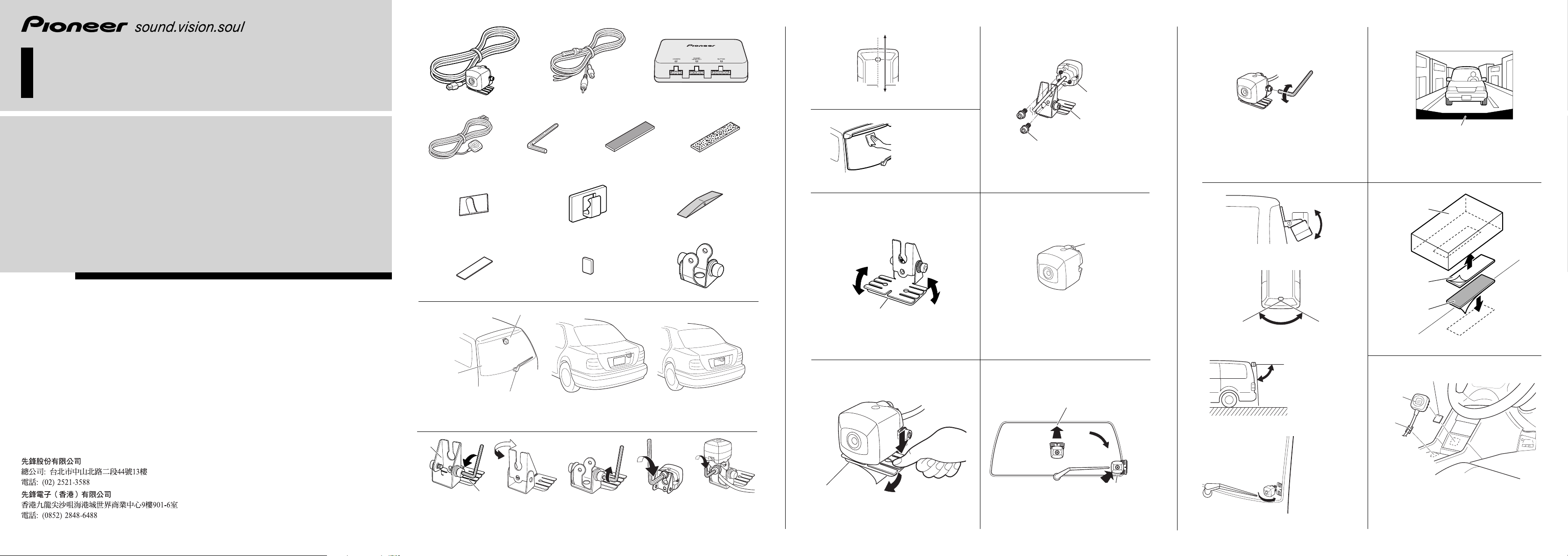
𝖠 Rear view camera × 1 𝖢 Image processing
𝖣 Button unit × 1
𝖤 Hexagon wrench × 1 𝖥 Velcro tape
𝖡 RCA power supply cable × 1
(soft type) × 1
unit power supply × 1
𝖦 Velcro tape
(hard type) × 1
Fig. 4
Abb. 4
Fig. 5
Abb. 5
① Top
② Rear view
camera
④ Installation
screw
③ Bottom
⑤ Camera stand
Fig. 6
Abb. 6
Fig. 11
Abb. 11
③ Bumper or rear edge of car
Fig. 13
Abb. 13
① Image processing unit
power supply
PIONEER CORPORATION
4-1, MEGURO 1-CHOME, MEGURO-KU, TOKYO 153-8654, JAPAN
PIONEER ELECTRONICS (USA) INC.
P.O. Box 1540, Long Beach, California 90801-1540, U.S.A.
TEL: (800) 421-1404
PIONEER EUROPE NV
Haven 1087, Keetberglaan 1, B-9120 Melsele, Belgium
TEL: (0) 3/570.05.11
PIONEER ELECTRONICS ASIACENTRE PTE. LTD.
253 Alexandra Road, #04-01, Singapore 159936
TEL: 65-6472-7555
PIONEER ELECTRONICS AUSTRALIA PTY. LTD.
178-184 Boundary Road, Braeside, Victoria 3195, Australia
TEL: (03) 9586-6300
PIONEER ELECTRONICS OF CANADA, INC.
300 Allstate Parkway, Markham, Ontario L3R 0P2, Canada
TEL: 1-877-283-5901
PIONEER ELECTRONICS DE MEXICO, S.A. de C.V.
Blvd. Manuel Avila Camacho 138 10 piso
Col. Lomas de Chapultepec, Mexico, D.F. 11000
TEL: 55-9178-4270
Published by Pioneer Corporation.
Copyright © 2007 by Pioneer Corporation.
All rights reserved.
Publié par Pioneer Corporation.
Copyright © 2007 par Pioneer Corporation.
Tous droits réservés.
Printed in Japan
Imprimé au Japon
<CZR5092-A> E<KKNNX> <07D00000>
𝖧 Metal clamp × 5
𝖪
Double-sided tape (rectangular) × 1
③ Install on the center part
① Glass surface
② Make sure it doesn’t touch the wiper
𝖡
Fig. 2
Abb. 2
𝖠
Fig. 3-1
Abb. 3-1
𝖫 Double-sided tape (square) × 1
Fig. 3-2
Abb. 3-2
𝖩 Waterproof pad × 1𝖨 Plastic clamp × 10
𝖬 Camera stand bracket 𝖢 × 1
Fig. 1
Abb. 1
Fig. 3-3
Abb. 3-3
Fig. 3-4
Abb. 3-4
① Turn
① Camera
stand
③ Camera stand
② Twist
Fig. 7
Abb. 7
Fig. 9
Abb. 9
① Top
③ Mark
② Bottom
Fig. 8
Abb. 8
② When sticking to the center
③ When attaching using camera stand bracket 𝖢
(attaching while rotating by 90°)
Fig. 10
Abb. 10
① Angle of view
Horizontal: 135°
② Angle of view
Fig. 12-1
Abb. 12-1
Fig. 12-2
Abb. 12-2
Vertical: 100°
Fig. 12-3
Abb. 12-3
Fig. 12-4
Abb. 12-4
② Velcro tape
(hard type)
③ Velcro tape
(soft type)
Fig. 14
Abb. 14
① Double-sided tape (square)
② Button unit
③ Metal
clamp
Fig. 15
Abb. 15
Page 2

Installation <ENGLISH>
Instalación <ESPANÕL>
Parts supplied
𝖠 Rear view camera × 1
𝖡 RCA power supply cable × 1
𝖢 Image processing unit power supply × 1
𝖣 Button unit × 1
𝖤 Hexagonal wrench × 1
𝖥 Velcro tape (soft type) × 1
𝖦 Velcro tape (hard type) × 1
𝖧 Metal clamp × 5
𝖨 Plastic clamp × 10
𝖩 Waterproof pad × 1
𝖪 Double-sided tape (rectangular) × 1
𝖫 Double-sided tape (square) × 1
𝖬 Camera stand bracket 𝖢 × 1
Installation example (Fig. 1)
① Glass surface
② Make sure it doesn’t touch the wiper
③ Install on the center part
Note:
• The position and angle of the image from the rear
view camera can still be adjusted using the initial
setup even if the camera is not installed in the
center of the vehicle. Refer to “First Time Setup”
in the Owner’s Manual for details.
Changing the orientation of camera
stand installation (Fig. 12-1)
The camera stand can be installed in
various ways by changing the direction in
which camera stand bracket 𝖡 is attached
or attaching camera stand bracket 𝖢.
Change to match your car’s shape or the
installation site.
1. Use the hexagon wrench to remove
the screws securing camera stand
brackets 𝖠 and 𝖡. (Fig. 2)
2. Change the direction of installation
bracket 𝖡. (Fig. 3-1)
3. Reattach with the screws.
Installing Using Camera Stand Bracket 𝖢
(Fig. 12-4)
1. Use the hexagon wrench to remove
the screws securing camera stand
brackets 𝖠 and 𝖡. (Fig. 2)
2. Attach camera stand bracket 𝖢 to
the camera stand. (Fig. 3-2)
3. Attach the rear view camera to cam-
era stand bracket 𝖡. (Fig. 3-3)
4. Attach the camera stand and rear
view camera. (Fig. 3-4)
Route the cables as shown in the figure so
that they do not become entangled.
Attach the camera stand while being
careful not to mistake the vertical
orientation
of the rear view camera. (Fig. 8)
Installation Procedure
Note:
• Before making a final installation of the unit,
temporarily connect the wiring to confirm that
the connections are correct and the system works
properly.
• Use only the parts included with the unit to ensure
proper installation. The use of unauthorized parts
can cause malfunctions.
• Consult with your nearest dealer if installation
requires the drilling of holes or other
modifications of the vehicle.
• Install the unit where it does not get in the driver’s
way and cannot injure the passenger if there is a
sudden stop, like an emergency stop.
• When mounting this unit, make sure none of
the leads are trapped between this unit and the
surrounding metalwork or fittings.
• To prevent electric shock, do not install the image
processing unit power supply in places where it
might come in contact with liquids.
• Do not mount this unit near the heater outlet,
where it would be affected by heat, or near the
doors, where rainwater might splash onto it.
(Never install in locations such as the above
because of the danger of malfunction due to high
temperatures.)
• Before drilling any mounting holes always check
behind where you want to drill the holes. Do not
drill into the gas line, brake line, electrical wiring
or other important parts.
• If this unit is installed in the passenger compartment,
anchor it securely so it does not break free while the
car is moving, and cause injury or an accident.
• If this unit is installed under a front seat, make
sure it does not obstruct seat movement. Route
all leads and cords carefully around the sliding
mechanism so they do not get caught or pinched
in the mechanism and cause a short circuit.
• Locate in the position you want to install the rear
view camera. Adjust the angle of the rear view
camera, and install so that the camera doesn’t
touch the car.
• When sticking to a glass surface, stick it on in a
position that assures the camera doesn’t touch the
rear window.
• Install so that it does not obstruct the rear field of
view.
• Install so that it does not protrude from the side of
the car.
• Do not perform installation in rain or fog.
• When humidity is high, dry the surface to which
the unit is to be attached before installing. Moisture
on the attachment surface reduces adhesive strength
which may lead to the unit coming off.
• Install so that the rear view camera is aligned in
parallel with the direction of vehicle movement
(straight back from the vehicle). (Fig. 4)
• Install the rear view camera above the license plate.
If the installed location of the rear view camera is
lower than the license plate, it will not be possible
to make image corrections causing distortion of the
image from the rear view camera.
• If the temperature of the attachment surface is
low, warm with a hair dryer of other means before
installing to improve adhesive strength.
• Do not attach the camera stand to areas on the car
body treated with fluorocarbon resin, or glass. This
may result in the rear view camera falling off.
• During the 24-hour period after installing:
– Do not apply water to the unit.
– Do not expose the unit to rain.
– Do not subject the camera to unnecessary force.
• Thoroughly clean where tape is used for sticking
on the unit.
1. Clean the surface to which the rear
view camera is to be installed.
(Fig. 5)
Use a cloth or other item to wipe oil, wax,
dust and any other dirt from the installation
surface.
2. Remove the rear view camera from
the camera stand. (Fig. 6)
Remove the mounting screws with the
hexagon wrench provided.
① Top
② Rear view camera
③ Bottom
④ Installation screw
⑤ Camera stand
3. Align the camera stand with the
installation surface. (Fig. 7)
Adjust the camera stand so that there is no
space between it and the installation surface.
① Turn
② Twist
③ Camera stand
4. Attach the camera stand removed in
step 2 to the rear view camera with
the mounting screws. (Fig. 8)
The rear view camera has a mark indicating
the top of the camera.
Attach the camera stand while being
careful not to mistake the vertical
orientation of the rear view camera.
① Top
② Bottom
③ Mark
5. Peel off the sheet on the back of they
camera stand and stick it on. (Fig. 9,
Fig. 10)
Press the camera stand with your fingers to
stick it to the installation surface. Touching
the adhesive surface or sticking the unit
on a second time reduces adhesive power
which may result in the unit coming off.
① Camera stand
② When sticking to the center
③ When attaching using camera stand bracket
𝖢 (attaching while rotating by 90°)
6. Adjust the angle so that the bumper
or rear edge of the car is displayed
at the bottom of the TV screen.
(Fig. 11, Fig. 12-2, Fig. 12-3, Fig. 13)
① Angle of view
Horizontal: 135°
② Angle of view
Vertical: 100°
③ Bumper or rear edge of car
Note:
• The angle shown varies according to the camera
specifications. The actual angle is narrower as a
result of image processing.
• The position and angle of the image from the
rear view camera can still be adjusted using the
initial setup even if the bumper or rear edge of
the car is not displayed on the bottom of the TV
screen. Refer to “First Time Setup” in the Owner’s
Manual for details.
7. Attach the image processing unit
power supply. (Fig. 14)
Affix the Velcro tape (hard type) to the
bottom of the image processing unit power
supply, and affix the Velcro tape (soft type)
to the mounting location.
① Image processing unit power supply
② Velcro tape (hard type)
③ Velcro tape (soft type)
• You can use Velcro tape (hard type) to attach
directly to a carpet, but do not use the soft type.
• Install the image processing unit power supply close enough for the rear view camera
cable to reach.
8. Attach the button unit (Fig. 15).
Affix the double-sided tape (square) to
the backside of the button unit. Next press
the unit onto the location where it will
be mounted. Affix the metal clamp to the
location where the cord is to be and then
secure the cord with the clamp.
① Double-sided tape (square)
② Button unit
③ Metal clamp
Piezas suministradas
𝖠 Cámara de vista posterior × 1
𝖡 Cable de suministro de energía RCA × 1
𝖢 Fuente de energía de la unidad de procesa-
miento de imagen × 1
𝖣 Unidad de botones × 1
𝖤 Llave hexagonal × 1
𝖥 Cinta Velcro (tipo blanda) × 1
𝖦 Cinta Velcro (tipo dura) × 1
𝖧 Abrazadera metálica × 5
𝖨 Abrazadera plástica × 10
𝖩 Almohadilla impermeable × 1
𝖪 Cinta de doble cara (rectangular) × 1
𝖫 Cinta de doble cara (cuadrada) × 1
𝖬 Ménsula del soporte de la cámara 𝖢 × 1
Ejemplo de instalación (Fig. 1)
① Superficie de vidrio
② Asegúrese de que no toque el limpiador
③ Instale en la pieza central
Nota:
• Todavía se puede ajustar la posición y el ángulo de la
imagen desde la cámara de vista posterior utilizando
la configuración inicial aunque la cámara no esté
instalada en el centro del vehículo. Para los detalles,
consulte la sección “Configuración por primera vez”.
Cambio de la orientación de la instalación
del soporte de la cámara (Fig. 12-1)
Se puede instalar el soporte de la cámara de
varias formas, cambiando la dirección en
la cual se fija la ménsula del soporte de la
cámara 𝖡, o fijando la ménsula del soporte
de la cámara 𝖢. Cambie de acuerdo con a
la forma de su coche o sitio de instalación.
1. Utilice la llave hexagonal para sacar
los tornillos que fijan las ménsulas 𝖠
y 𝖡 del soporte de la cámara. (Fig. 2)
2. Cambie la dirección de la ménsula
de instalación 𝖡. (Fig. 3-1)
3. Vuelva a fijar con los tornillos.
Instalación utilizando la ménsula del
soporte de la cámara 𝖢 (Fig. 12-4)
1. Utilice la llave hexagonal para sacar
los tornillos que fijan las ménsulas 𝖠
y 𝖡 del soporte de la cámara. (Fig. 2)
2. Fije la ménsula del soporte de la
cámara 𝖢 al soporte de la cámara.
(Fig. 3-2)
3. Fije la cámara de vista posterior a la
ménsula del soporte de la cámara 𝖡.
(Fig. 3-3)
4. Fije el soporte de la cámara y la
cámara de vista posterior. (Fig. 3-4)
Encamine los cables como se muestra en la
figura de modo que no queden enredados.
Fije el soporte de la cámara teniendo
cuidado en no invertir la orientación
vertical de la cámara de vista superior.
(Fig. 8)
Procedimiento de instalación
Nota:
• Antes de la instalación final de la unidad, conecte
el cableado temporalmente y confirme que las
conexiones son correctas y que el sistema trabaja
normalmente.
• Utilice solamente las partes incluídas con la unidad
para asegurar una instalación adecuada. El uso de
partes no autorizadas puede ocasionar fallas de
funcionamiento.
• Si la instalación requiere del taladrado de orificios u
otras modificaciones del vehículo, consulte con su
agente o concesionario más cercano a su domicilio.
• Instale la unidad en donde no interfiera con el
conductor y no pueda lesionar al pasajero en caso
de una parada repentina, tal como una frenada de
emergencia.
• Cuando monte esta unidad, cerciórese que ninguno
de los cables queda aprisionado entre esta unidad y
accesorios o partes metálicas circundantes.
• Para prevenir descargas eléctricas, no instale la fuente
de energía de la unidad de procesamiento de imagen
en lugares donde pueda entrar en contacto con
líquidos.
• No monte esta unidad cerca de la salida del calefactor,
en donde podría ser afectado por el calor o cerca
de las puertas, en donde la lluvia podría salpicar
sobre la misma. (Para evitar el riego de fallos de
funcionamiento producidos por las altas temperaturas,
evite la instalación en los lugares arriba.)
• Antes de taladrar cualquier orificio de montaje
siempre compruebe lo que hay detrás en donde
desea taladrar los orificios. No taladre en la línea
de combustible, cableado eléctrico u otras partes
importantes.
• Si esta unidad es instalada en el compartimiento de
pasajeros, fíjela seguramente de modo que no se
desprenda mientras el automóvil se encuentra en
movimiento, y pueda ocasionar lesiones o accidentes.
• Si esta unidad se instale bajo un asiento delantero,
cerciórese de que no obstruye el movimiento
del asiento. Pase todos los cables y conductores
cuidadosamente a través de los mecanismo
deslizantes, de modo que no queden aprisionados
o atrapados en el mecanismo y ocasionen un corto
circuito.
Page 3

Instalación <ESPANÕL>
Einbau <DEUTSCH>
• Encuentre la posición que desea instalar la cámara
de vista posterior. Ajuste el ángulo de la cámara de
vista posterior, e instale de modo que la cámara no
toque el coche.
• Cuando fije a una superficie de vídeo, fíjela en una
posición que asegure que la cámara no toque la
ventana trasera.
• Instale de modo que no obstruya el campo de vista
trasero.
• Instale de modo que no se sobresalga del lado del
coche.
• No realice la instalación en la lluvia o niebla.
• Cuando la humedad está alta, seque la superficie
a la cual fijará la unidad antes de instalar. La
humedad de la superficie de fijación reduce la
resistencia de adherencia, lo que puede soltar la
unidad.
• Instale de modo que la cámara de vista posterior
quede alineada en una línea paralela con la
dirección de movimiento del vehículo (en una
línea recta atrás del vehículo). (Fig. 4)
• Instale la cámara de vista posterior encima de la
chapa de matrícula. Si la ubicación de instalación
de la cámara de vista posterior es más baja que
la chapa de matrícula, no será posible hacer las
correcciones de la imagen, causando la distorsión
de la imagen desde la cámara de vista posterior.
• Si la temperatura de la superficie de fijación está baja,
caliente con un secador de pelo u otro medio antes de
instalar, para mejorar la resistencia de adherencia.
• No fije el soporte de la cámara en áreas en
la carrocería del coche tratadas con resina de
fluorocarburo, o vidrio. Esto puede resultar en la
caída de la cámara de vista posterior.
• Durante el período de 24 horas tras la instalación:
– No aplique agua a la unidad.
– No exponga la unidad a la lluvia.
– No sujete la cámara a la fuerza innecesaria.
• Limpie completamente el sitio donde se utilizará
la cinta para fijar la unidad.
1. Limpie la superficie a la cual
se instalará la cámara de vista
posterior. (Fig. 5)
Utilice un paño u otro ítem para limpiar el
aceite, cera y cualquier otra suciedad de la
superficie de instalación.
2. Extraiga la cámara de vista poste-
rior del soporte de la cámara. (Fig.
6)
Extraiga los tornillos de montaje con la
llave hexagonal suministrada.
① Parte superior
② Cámara de vista posterior
③ Parte inferior
④ Tornillo de instalación
⑤ Soporte de la cámara
3. Alinee el soporte de la cámara con la
superficie de instalación. (Fig. 7)
Ajuste el soporte de la cámara de modo
que no quede ningún espacio entre ello y la
superficie de instalación.
① Gire
② Retuerza
③ Soporte de la cámara
4. Fije el soporte de la cámara extraído
en el paso 2 a la cámara de vista
posterior con los tornillos de
montaje. (Fig. 8)
La cámara de vista posterior tiene una
marca que indica la parte superior de la
cámara.
Fije el soporte de la cámara teniendo
cuidado en no invertir la orientación
vertical de la cámara de vista superior.
① Parte superior
② Parte inferior
③ Marca
5. Quite la hoja de la parte posterior
del soporte de la cámara y fije.
(Fig. 9, Fig. 10)
Presione el soporte de la cámara con
los dedos para fijarlo en la superficie de
instalación. Tocar la superficie adhesiva
o fijar la unidad una segunda vez reduce
la resistencia de adherencia, lo que puede
resultar en el despegamiento de la unidad.
① Soporte de la cámara
② Cuando pegue al centro
③ Cuando fije utilizando la ménsula del soporte
de la cámara 𝖢 (fijación girando 90°)
6. Ajuste el ángulo de modo que el
parachoques o borde trasero del
coche se visualice en la parte inferior
de la pantalla de TV. (Fig. 11,
Fig. 12-2, Fig. 12-3, Fig. 13)
① Ángulo de visión
Horizontal: 135°
② Ángulo de visión
Vertical: 100°
③ Parachoques o borde trasero del coche
Nota:
• El ángulo que se muestra varía de acuerdo con las
especificaciones de la cámara. El ángulo real es más
estrecho como un resultado del procesamiento de la
imagen.
• Todavía se puede ajustar la posición y el ángulo de la
imagen desde la cámara de vista posterior utilizando
la configuración inicial aunque no se visualice el
parachoques o el borde trasero del vehículo en la
parte inferior de la pantalla. Consulte la sección
“Configuración por primera vez” en el Manual del
Propietario para los detalles.
7. Instale la fuente de energía de la
unidad de procesamiento de imagen.
(Fig. 14)
Fije la cinta velcro (tipo dura) al fondo
de la fuente de energía de la unidad de
procesamiento de imagen, y fije la cinta
velcro (tipo blanda) a la ubicación de
montaje.
① Fuente de energía de la unidad de procesa-
miento de imagen
② Cinta velcro (tipo dura)
③ Cinta velcro (tipo blanda)
• Puede utilizar la cinta velcro (tipo dura) para
fijar directamente a una alfombra, pero no
utilice el tipo de cinta blanda.
• Instale la fuente de energía de la unidad de
procesamiento de imagen lo suficiente cercana para que el cable de la cámara de vista
posterior la alcance.
8.
Instale la unidad de botones (Fig. 15).
Fije la cinta de doble cara (cuadrada) al
lado posterior de la unidad de botones.
Luego, presione la unidad en la posición
donde se la montará. Instale la abrazadera
metálica en la posición donde el cable
deberá quedarse y, a continuación, fije el
cable con la abrazadera.
① Cinta de doble cara (cuadrada)
② Unidad de botones
③ Abrazadera metálica
Mitgelieferte Teile
𝖠 Heckkamera × 1
𝖡 Cinch-Stromkabel × 1
𝖢 Netzteil der Bildverarbeitungseinheit × 1
𝖣 Tasteneinheit × 1
𝖤 Sechskantschlüssel × 1
𝖥 Klettband (weich) × 1
𝖦 Klettband (hart) × 1
𝖧 Metallklemme × 5
𝖨 Plastikklemme × 10
𝖩 Wasserschutzkissen × 1
𝖪 Doppelseitiges Klebeband (rechteckig) × 1
𝖫 Doppelseitiges Klebeband (quadratisch) × 1
𝖬 Kamerahalterplatte 𝖢 × 1
Installationsbeispiel (Abb. 1)
① Glasscheibe
② Keine Behinderung des Scheibenwischers
③ In der Mitte installieren
Hinweis:
• Position und Winkel des Bildes von der
Heckkamera können selbst dann mit der
anfänglichen Einstellung eingestellt werden, wenn
die Kamera nicht in der Mitte des Fahrzeugs
installiert ist. Siehe “Erste Einstellung” im
Besitzerhandbuch für weitere Einzelheiten.
Ändern des KamerahalterNeigungswinkels (Abb. 12-1)
Der Kamerahalter kann auf verschiedene
Weise installiert werden, indem
Sie die Richtung ändern, in der die
Kamerahalterplatte 𝖡 angebracht ist
oder indem Sie die Kamerahalterplatte 𝖢
anbringen. Passen Sie den Neigungswinkel
der Form Ihres Autos oder der
Installationsfläche an.
1. Lösen Sie die Befestigungsschrauben
der KamerahalterMontageplatten 𝖠 und 𝖡 mit dem
Sechskantschlüssel. (Abb. 2)
2. Ändern Sie die Richtung der
Montageplatte 𝖡. (Abb. 3-1)
3. Befestigen Sie die Schrauben wieder.
Anbringen der Kamerahalterplatte 𝖢
(Abb. 12-4)
1. Lösen Sie die Befestigungsschrauben
der KamerahalterMontageplatten 𝖠 und 𝖡 mit dem
Sechskantschlüssel. (Abb. 2)
2. Befestigen Sie die
Kamerahalterplatte 𝖢 am
Kamerahalter. (Abb. 3-2)
3. Befestigen Sie die Heckkamera an
der Kamerahalterplatte 𝖡. (Abb. 3-3)
4. Befestigen Sie den Kamerahalter
und die Heckkamera. (Abb. 3-4)
Ordnen Sie die Kabel wie in der Abbildung
gezeigt an, damit sie sich nicht verwirren.
Bringen Sie den Kamerahalter an,
wobei Sie darauf achten, die senkrechte
Ausrichtung der Heckkamera nicht zu
vertauschen. (Abb. 8)
Installationsverfahren
Hinweis:
• Schließen Sie vor dem endgültigen Einbau der
Geräte die Leitungen vorübergehend an, um sich
zu vergewissern, dass alles richtig angeschlossen
ist und das System einwandfrei funktioniert.
• Um richtige Montage zu gewährleisten, nur die
mit dem Gerät mitgelieferten Teile verwenden.
Durch den Gebrauch von nicht zugelassenen
Teilen können Funktionsstörungen verursacht
werden.
• Setzen Sie sich mit einem Händler in Ihrer Nähe
in Verbindung, wenn die Montage Bohren von
Löchern oder andere Modifikationen am Fahrzeug
erfordert.
• Das Gerät so montieren, dass es den Fahrer nicht
behindern und im Falle einer Notbremsung den
Beifahrer nicht verletzen kann.
• Bei Montage des Geräts sicherstellen, dass keine
Leitung zwischen dem Gerät und umgebenden
Metallteilen oder Beschlägen eingeklemmt wird.
• Um Stromschläge zu vermeiden, installieren Sie
das Netzteil der Bildverarbeitungseinheit nicht an
Orten an denen es Flüssigkeiten ausgesetzt sein
könnte.
• Das Gerät nicht in der Nähe eines
Warmluftauslasses, wo es durch Wärme
beeinträchtigt werden könnte, oder in der
Nähe der Türen montieren, wo es bei Regen
Feuchtigkeit ausgesetzt sein könnte. (Vermeiden
Sie die Installation an obigen Orten, weil sonst
die Gefahr von Funktionsstörungen wegen hoher
Temperaturen besteht.)
• Bevor irgendwelche Montagelöcher gebohrt
werden, stets nachkontrollieren, was sich hinter
der vorgesehenen Bohrstelle befindet. Darauf
achten, nicht in Kraftstoffleitung, Bremsleitung,
ein elektrisches Kabel oder andere wichtige Teile
zu bohren.
• Falls dieses Gerät im Beifahrerraum montiert wird,
muss es sicher verankert werden, sodass es sich
während der Fahrt nicht lösen und Verletzungen
bzw. einen Unfall verursachen kann.
• Falls dieses Gerät unter einem Vordersitz montiert
wird, sicherstellen, dass der Sitz nach wie vor voll
verschoben werden kann. Alle Kabel sorgfältig
um den Verschiebemechanismus verlegen, sodass
sie sich nicht verfangen oder eingeklemmt werden
können, um Kurzschlüsse zu vermeiden.
• Legen Sie die Installationsposition der
Heckkamera fest. Stellen Sie den Winkel der
Heckkamera ein, und installieren Sie die Kamera
so, dass sie das Auto nicht berührt.
• Wenn Sie die Kamera an der Heckscheibe
befestigen, bringen Sie sie so an, dass sie die
Heckscheibe nicht berührt.
• Installieren Sie die Kamera so, dass sie das
Sichtfeld nach hinten nicht behindert.
• Installieren Sie die Kamera so, dass sie nicht
seitlich vom Auto übersteht.
• Führen Sie die Installation nicht bei Regen oder
Nebel durch.
• Bei hoher Luftfeuchtigkeit ist es empfehlenswert,
die Anbringungsfläche der Kamera vor der
Installation zu trocknen. Feuchtigkeit auf der
Anbringungsfläche reduziert die Haftfestigkeit.
Dies kann dazu führen, dass sich die Kamera löst.
• Führen Sie die Installation so durch, dass
die Heckkamera parallel zur Fahrtrichtung
ausgerichtet ist (vom Fahrzeug gerade nach
hinten) (Abb. 4).
• Installieren Sie die Heckkamera über dem
Nummernschild. Falls sich die Heckkamera
unterhalb des Nummernschilds befindet, können
keine Bildkorrekturen durchgeführt werden,
was zu einer Verzerrung der Bilder von der
Heckkamera führen würde.
• Falls die Temperatur der Anbringungsfläche
niedrig ist, erwärmen Sie sie vor der Installation
mit einem Haartrockner oder einem anderen
Hilfsmittel, um die Haftfestigkeit zu verbessern.
• Befestigen Sie den Kamerahalter nicht an
Karosserieflächen, die mit Fluorkunststoff oder
Glas überzogen sind. Es besteht sonst die Gefahr,
dass die Heckkamera herunterfällt.
• Während der ersten 24 Stunden nach der
Installation:
– Halten Sie Wasser von der Kamera fern.
– Setzen Sie die Kamera keinem Regen aus.
– Setzen Sie die Kamera keiner unnötigen
Krafteinwirkung aus.
• Unterziehen Sie die Klebeband-Haftflächen
zur Anbringung der Einheit einer gründlichen
Reinigung.
1. Reinigen Sie die vorgesehene
Installationsfläche der Heckkamera.
(Abb. 5)
Wischen Sie Öl, Wachs, Staub und
sonstigen Schmutz mit einem Tuch o. Ä.
von der Installationsfläche ab.
2. Nehmen Sie die Heckkamera vom
Kamerahalter ab. (Abb. 6)
Entfernen Sie die Montageschrauben mit
dem mitgelieferten Sechskantschlüssel.
① Oberseite
② Heckkamera
③ Unterseite
④ Befestigungsschraube
⑤ Kamerahalter
3. Richten Sie den Kamerahalter auf
die Installationsfläche aus. (Abb. 7)
Stellen Sie den Kamerahalter so ein, dass
kein Spielraum zwischen dem Halter und
der Installationsfläche vorhanden ist.
① Drehen
② Verdrehen
③ Kamerahalter
4. Bringen Sie den in Schritt 2
abgenommenen Kamerahalter mit
den Montageschrauben an der
Heckkamera an. (Abb. 8)
Die Heckkamera weist eine Markierung
auf, die die Oberseite der Kamera
kennzeichnet.
Bringen Sie den Kamerahalter an, wobei Sie
darauf achten, die senkrechte Ausrichtung der
Heckkamera nicht zu vertauschen.
① Oberseite
② Unterseite
③ Markierung
5. Lösen Sie die Schutzfolie von der
Rückseite des Kamerahalters ab,
und bringen Sie den Halter an.
(Abb. 9, Abb. 10)
Drücken Sie den Kamerahalter mit
den Fingern an, um ihn auf die
Installationsfläche zu kleben. Wenn Sie die
Klebefläche berühren oder den Halter ein
zweites Mal ankleben,
verringert sich die Haftfestigkeit. Dies kann
dazu führen, dass sich der Halter löst.
① Kamerahalter
② Beim Aufkleben in der Mitte
③ Beim Befestigen mit Hilfe der
Kameraträgerplatte 𝖢 (Befestigung mit
Drehen um 90°)
Page 4

Einbau <DEUTSCH>
Installation <FRANÇAIS>
6. Stellen Sie den Winkel so ein, dass
der Stoßfänger oder das Heck des
Autos noch am unteren Rand des
Monitorschirms angezeigt wird.
(Abb. 11, Abb. 12-2, Abb. 12-3,
Abb. 13)
① Blickwinkel
Horizontal: 135°
② Blickwinkel
Vertikal: 100°
③ Stoßfänger oder Heck des Autos
Hinweise:
• Der angezeigte Winkel ist je nach
Kameraspezifikation verschieden. Der tatsächliche
Winkel ist infolge der Bildverarbeitung schmaler.
• Position und Winkel des Bildes von der
Heckkamera können selbst dann mit der
anfänglichen Einstellung eingestellt werden, wenn
die Stostange oder das hintere Ende des Fahrzeugs
nicht an der Unterseite des Fernsehbildschirms
angezeigt werden. Siehe “Erste Einstellung” im
Besitzerhandbuch für weitere Einzelheiten.
7. Bringen Sie das Netzteil der
Bildverarbeitungseinheit. (Abb. 14)
Befestigen Sie das Klettband (hart)
an der Unterseite das Netzteil der
Bildverarbeitungseinheit, und befestigen
Sie dann das Klettband (weich) am
Installationsort.
① Netzteil der Bildverarbeitungseinheit
② Klettband (hart)
③ Klettband (weich)
• Sie können die Einheit mit Klettband
(hart) direkt an einem Teppich anbringen.
Verwenden Sie dazu aber nicht das weiche
Klettband.
• Installieren Sie das Netzteil der
Bildverarbeitungseinheit so, dass das
Heckkamerakabel lang genug ist.
8. Bringen Sie die die Tasteneinheit an
(Abb. 15).
Befestigen Sie das doppelseitige Klebeband
(quadratisch) an der Rückseite der
Tasteneinheit. Drücken Sie die Einheit
dann auf die Stelle, wo sie befestigt werden
soll. Befestigen Sie die Metallklemme an
der Stelle, wo das Kabel verlaufen soll,
und sichern Sie das Kabel dann mit der
Klemme.
① Tasteneinheit
② Metallklemme
③ Doppelseitiges Klebeband (quadratisch)
Pièces fournies
𝖠 Caméra de recul × 1
𝖡 Câble à fiche Cinch (RCA) d’alimentation × 1
𝖢 Unité d’alimentation et de traitement de
l’image × 1
𝖣 Unité de commande × 1
𝖤 Clé six pans × 1
𝖥 Bande Velcro (souple) × 1
𝖦 Bande Velcro (rigide) × 1
𝖧 Attaches métalliques × 5
𝖨 Attaches de plastique × 10
𝖩 Garniture étanche × 1
𝖪 Ruban adhésif double-face (rectangulaire) × 1
𝖫 Ruban adhésif double-face (carré) × 1
𝖬 Applique de support de la caméra 𝖢 × 1
Exemple d’installation (Fig. 1)
① Surface vitrée
② Assurez-vous que la caméra ne gêne pas
l’essuie-glace
③ Centrez la caméra
Remarque:
• La position et l’angle de l’image de la caméra de
recul peut aussi être ajustée en utilisant le réglage
initial même si la caméra n’est pas installée au
centre du véhicule. Reportez-vous à “Premier
réglage” dans le mode d’emploi pour en savoir
plus.
Changement de l’orientation du
support de la caméra (Fig. 12-1)
Le support de la caméra peut être installé
de différentes façons en changeant la
direction dans laquelle l’applique du
support de la caméra 𝖡 est attachée ou
en attachant l’applique du support de la
caméra 𝖢. Choisissez en fonction de la
forme du véhicule et de l’emplacement
d’installation.
1. Utilisez la clé six pans pour retirer
les vis qui maintiennent les platines
𝖠 et 𝖡 du support de la caméra.
(Fig. 2)
2. Changez l’orientation du support
d’installation 𝖡. (Fig. 3-1)
3. Refixez-le avec les vis.
Installation en utilisant l’applique du support de la caméra 𝖢 (Fig. 12-4)
1. Utilisez la clé six pans pour retirer
les vis qui maintiennent les platines
𝖠 et 𝖡 du support de la caméra.
(Fig. 2)
2. Attachez l’applique du support de
la caméra 𝖢 sur le support de la
caméra. (Fig. 3-2)
3. Attachez la caméra de recul sur
l’applique du support de la caméra
𝖡. (Fig. 3-3)
4. Attachez le support de la caméra et
la caméra de recul. (Fig. 3-4)
Acheminez les câbles comme montré sur
la figure de façon qu’ils ne s’emmêlent pas.
Fixez le support de la caméra de recule en
faisant attention de pas vous tromper pour
l’orientation verticale de la caméra. (Fig. 8)
Procédure d’installation
Remarque:
• Avant de finaliser l’installation de l’appareil,
connecter temporairement le câblage pour s’assurer
que les connexions sont correctes et que le système
fonctionne convenablement.
• Pour effectuer convenablement l’installation, utilisez
les pièces fournies et procédez comme il est indiqué.
L’utilisation de pièces autres que celles fournies peut
endommager l’appareil.
• Avant d’effectuer un perçage ou une modification du
véhicule, consultez le concessionnaire.
• N’installez pas l’appareil dans un endroit où il pourrait
gêner le conducteur ou blesser un passager en cas de
freinage brusque, par exemple pour un arrêt d’urgence.
• Veillez à ce que les câbles ne puissent pas être pincés
entre l’appareil et les pièces métalliques environnantes.
• Pour éviter les chocs électriques, n’installez pas l’unité
d’alimentation et de traitement de l’image dans un
endroit où elle peut entrer en contact avec de l’eau.
• N’installez pas cet appareil près d’une bouche de
chauffage car la chaleur dégagée peut l’endommager;
pareillement, évitez la proximité des portières
car il pourrait être éclaboussé par la pluie ou les
intempéries. (Ne jamais installer cet appareil dans
des emplacements tels que ceux indiqués ci-dessus,
à cause des risques de dysfonctionnement causés par
des températures trop élevées.)
• Avant d’effectuer un perçage requis par l’installation de
l’appareil, assurez-vous que vous pouvez le faire sans
danger pour les câbles, canalisations, flexibles, etc., qui
sont placés derrière le panneau que vous devez percer.
• Si vous installez l’appareil dans l’habitacle, veillez à
ce qu’il soit bien ancré de manière qu’il ne puisse pas
provoquer une blessure ou un accident en raison du
déplacement du véhicule sur la route.
• Si vous choisissez d’installer l’appareil sous un siège
avant, veillez à ce qu’il ne gêne pas la manoeuvre du
siège. Faites cheminer les câbles et les conducteurs de
telle manière qu’ils ne puissent pas gêner le réglage du
siège ni être endommagés par son déplacement, ce qui
pourrait provoquer un court-circuit.
• Déterminez l’emplacement où vous désirez installer la
caméra de recul. Réglez l’inclinaison de la caméra et
fixez-la de telle sorte qu’elle ne touche pas le véhicule.
• Si vous la fixez à une surface vitrée, choisissez un
endroit où la caméra ne risque pas d’entrer en contact
avec la vitre arrière.
• Installez la caméra de façon qu’elle n’obstrue pas le
champ de vision vers l’arrière.
• Choisissez un emplacement tel que la caméra ne fasse
pas saillie sur un côté du véhicule.
• N’effectuez pas l’installation par temps de pluie ou de
brouillard.
• Si l’humidité est élevée, séchez préalablement la surface
de pose. L’humidité réduit la puissance de l’adhésif et la
caméra peut ultérieurement se détacher.
• Faites l’installation de façon que la caméra de recul
soit alignée de façon parallèle avec la direction du
mouvement du véhicule (en ligne droite derrière le
véhicule). (Fig. 4)
• Installez la caméra de recul au-dessus de la plaque
d’immatriculation.
Si l’emplacement d’installation de la caméra de recul est
plus bas que la plaque d’immatriculation, il ne sera pas
possible de faire des corrections d’image des distorsions
de l’image de la caméra de recul.
• Si la température de la surface de pose est basse,
réchauffez-la à l’aide d’un sèche-cheveux, ou tout
autre moyen convenable, de manière à tirer parti de
toute la puissance de l’adhésif.
• Ne fixez pas le support de la caméra à un élément de
la carrosserie traité avec une résine fluorocarbonée, ni
à un élément en verre. La caméra pourrait se détacher.
• Au cours des 24 heures qui suivent l’installation:
– Ne mouillez pas la caméra.
– Ne l’exposez pas à la pluie.
– N’exercez aucune contrainte inutile sur la caméra.
• Nettoyez soigneusement l’emplacement où vous
devez poser le ruban adhésif.
1. Nettoyez l’emplacement de pose de
la caméra. (Fig. 5)
À l’aide d’un chiffon, essuyez les traces
d’huile ou de cire, les poussières et les
saletés qui se seraient déposées à
l’emplacement de pose.
2. Retirez la caméra de recul de son
support. (Fig. 6)
Retirez les vis de montage avec la clé six
pans fournie.
① Haut
② Caméra de recul
③ Bas
④ Vis d’installation
⑤ Support de la caméra
3. Présentez le support de la caméra à
l’emplacement de pose. (Fig. 7)
Positionnez le support de la caméra de
manière qu’il n’existe aucun espace entre
le support et la surface de pose.
① Tournez
② Inclinez
③ Support de caméra
4. Fixez le support de la caméra de
recul retiré à l’étape 2 sur la caméra
avec les vis de montage. (Fig. 8)
La caméra de recul a un repère indiquant le
dessus de la caméra.
Fixez le support de la caméra de recule en
faisant attention de pas vous tromper pour
l’orientation verticale de la caméra.
① Haut
② Bas
③ Repère
5. Retirez la feuille de protection à
l’arrière du support de caméra et
collez ce dernier. (Fig. 9, Fig. 10)
Appuyez des doigts sur le support de
caméra pour qu’il colle à l’emplacement
de pose. En touchant la surface adhésive,
ou en décollant et recollant le support une
seconde fois, vous réduisez la puissance de
l’adhésif et ultérieurement la caméra peut
se détacher.
① Support de la caméra
② Lorsque vous collez au centre
③ Lorsque vous attachez la caméra en utilisant
l’applique du support de la caméra 𝖢 (fixation avec rotation de 90°)
6. Réglez l’inclinaison de manière que
le pare-choc ou l’extrémité arrière du
véhicule viennent s’afficher à la partie
inférieure de l’écran de télévision.
(Fig. 11, Fig. 12-2, Fig. 12-3, Fig. 13)
① Angle de vision
Horizontal: 135°
② Angle de vision
Vertical: 100°
③ Pare-choc ou extrémité du véhicule
Remarque:
• L’angle indiqué varie en fonction des
caractéristiques de la caméra. L’angle réel est plus
étroit à cause du traitement de l’image.
• La position et l’angle de l’image de la caméra de
recul peuvent être ajustés en utilisant le réglage
initial même si le pare-chocs ou le bord arrière de
la voiture n’est pas affiché en bas de l’écran de
télévision. Reportez-vous à “Premier réglage” dans
le mode d’emploi pour en savoir plus.
7. Attachez l’unité d’alimentation et de
traitement de l’image fournie. (Fig.
14)
Fixez la bande Velcro (rigide) sur le dessous
de l’unité d’alimentation et de traitement
de l’image et fixez la bande Velcro (souple)
sur l’emplacement d’installation.
① Unité d’alimentation et de traitement de
l’image
② Bande Velcro (rigide)
③ Bande Velcro (souple)
• La bande Velcro (rigide) permet de fixer
l’alimentation directement sur le tapis du
véhicule, mais cela n’est pas vrai de la bande
Velcro (souple).
• Installez l’unité d’alimentation et de
traitement de l’image suffisamment près pour
que le câble de la caméra de recul puisse
l’atteindre.
8. Attachez l’unité de commande
(Fig. 15).
Fixez le ruban adhésif double-face
(carré) au dos de l’unité de commande.
Faites ensuite pression sur l’appareil à
l’emplacement où il doit être monté. Fixez
les attaches métalliques sur le chemin du
cordon et fixez le cordon avec les attaches.
① Ruban adhésif double-face (carré)
② Unité de commande
③ Attaches métalliques
Page 5

Installazione <ITALIANO>
Il disegno delle parti fornite e le figure da 1 a
15 sono mostrati sul lato opposto.
Parti fornite
𝖠 Videocamera di visione posteriore × 1
𝖡 Cavo di alimentazione RCA × 1
𝖢 Alimentatore dell’unità di elaborazione
immagini × 1
𝖣 Pulsantiera × 1
𝖤 Chiave esagonale × 1
𝖥 Nastro velcro (tipo morbido) × 1
𝖦 Nastro velcro (tipo rigido) × 1
𝖧 Fermacavo metallico × 5
𝖨 Fermacavo di plastica × 10
𝖩 Imbottitura impermeabile × 1
𝖪 Nastro a doppio lato adesivo (rettangolare)
× 1
𝖫 Nastro a doppio lato adesivo (quadrato) × 1
𝖬 Staffa di supporto videocamera 𝖢 × 1
Esempio d’installazione (Fig. 1)
① Superficie di vetro
② Accertarsi che non vada a contatto con il
tergicristallo
③ Installare sulla parte centrale
Nota:
• La posizione e l’angolo dell’immagine trasmessa
dalla videocamera di visione posteriore sono
regolabili durante l’impostazione iniziale anche
se l’apparecchio non è installato al centro del
veicolo. Per informazioni al riguardo si prega
di vedere la sezione “Impostazione iniziale” del
manuale d’istruzioni.
Modifica dell’orientamento del
supporto della videocamera (Fig. 12-1)
Il supporto della videocamera di visione
posteriore può essere installato in svariati modi
semplicemente cambiando l’orientamento di
montaggio della staffa di supporto 𝖡 oppure
fissando la staffa di supporto 𝖢 stessa.
Procedete quindi con la modifica in base alla
forma dell’autoveicolo o al punto d’installazione
desiderato.
1. Utilizzando la chiave esagonale,
rimuovete le viti di fissaggio dalle
staffe 𝖠 e 𝖡 del supporto della
videocamera. (Fig. 2)
2. Modificate l’orientamento della
staffa 𝖡. (Fig. 3-1)
3. Fissatela nuovamente con le viti.
Installazione della videocamera di visione
posteriore con la staffa di supporto 𝖢
(Fig. 12-4)
1. Utilizzando la chiave esagonale,
rimuovete le viti di fissaggio dalle
staffe 𝖠 e 𝖡 del supporto della
videocamera. (Fig. 2)
2. Fissare la staffa 𝖢 al supporto della
videocamera. (Fig. 3-2)
3. Fissare la videocamera alla staffa di
supporto 𝖡. (Fig. 3-3)
4. Montare la videocamera di visione
posteriore sul supporto. (Fig. 3-4)
Convogliare i cavi come mostrato in figura
affinché non si aggroviglino.
Mentre fissate il supporto della
videocamera fate attenzione a non
invertirne l’orientamento verticale. (Fig. 8)
Procedura d’installazione
Nota:
• Prima di installare definitivamente l’apparecchio,
collegare i fili temporaneamente per accertarsi che
tutti i collegamenti siano corretti e che l’apparecchio e
il sistema funzionino correttamente.
• Realizzare una installazione appropriata facendo uso delle
sole parti fornite insieme a questo apparecchio. L’uso di
pezzi non autorizzati può essere all’origine di disfunzioni.
• Se l’installazione richiede l’apertura di fori, o altre
modifiche al veicolo, rivolgersi ad un rivenditore.
• Installare l’apparecchio in un luogo dove non risulti
di impedimento ai movimenti del guidatore, e non
abbia a causare lesioni ai passeggeri in caso di arresti
improvvisi del veicolo per situazioni di emergenza.
• Nel corso dell’installazione verificare che i cavi non
vengano a trovarsi strizzati fra l’apparecchio stesso e
le montature ed altri infissi di metallo circostanti.
• Per prevenire le scosse elettriche, l’alimentatore
dell’unità di elaborazione immagini non deve essere
installato in punti ove possa andare a contatto con
liquidi.
• Non installare l’apparecchio nelle vicinanze della bocca
del riscaldamento, dove potrebbe subire l’influenza del
flusso di aria calda, o nelle vicinanze delle portiere,
dove potrebbe trovarsi esposto alla pioggia. (Mai
installare nei luoghi sopra descritti a causa del pericolo
di malfuziona-mento dovuto alle alte temperature.)
• Prima di aprire un foro, verificare sempre il lato
opposto del pannello dove si intende effettuare la
perforazione. Non aprire fori sulle linee dei tubi del
carburante o dei freni, sui cablaggi elettrici, e su altre
parti importanti per il funzionamento del veicolo.
• Se l’apparecchio viene montato all’interno
dell’abitacolo della vettura, ancorarlo saldamente, in
modo che non abbia a staccarsi mentre la vettura è in
movimento, causando possibili lesioni agli occupanti,
o incidenti stradali.
• Se l’apparecchio viene installato sotto uno dei sedili
anteriori, verificare che la posizione non blocchi il
movimento del sedile stesso. Istradare tutti i cavi
con cura all’intorno del meccanismo di scorrimento,
in modo che non vengano a trovarsi presi nei
meccanismi, con conseguenti possibili corti circuiti.
• Individuate la posizione nella quale desiderate installare la
videocamera di visione posteriore. Regolate l’angolazione
della videocamera di visione posteriore ed installatela in
modo che non vada a contatto con il veicolo.
• In caso di fissaggio della videocamera ad una
superficie di vetro, posizionatela in un punto ove non
vada a contatto con il finestrino posteriore.
• Installatela in modo che non ostruisca il campo visivo
posteriore.
• Installatela in modo che non sporga dai lati del veicolo.
• Non eseguite l’installazione sotto la pioggia o in
presenza di nebbia.
• In caso di elevata umidità, prima di avviare
l’installazione asciugate bene la zona in cui
l’unità andrà fissata. L’eventuale presenza di umidità
sulla superficie di fissaggio riduce la forza adesiva,
condizione che può portare al distacco dell’unità.
• La videocamera di visione posteriore deve essere
installata affinché risulti parallela alla direzione di
movimento del veicolo. (Fig. 4)
• La videocamera deve essere installata in posizione
elevata rispetto alla targa del veicolo. Se la s’installa
sotto la targa non è possibile correggere l’immagine
visualizzata, la quale apparirà così distorta.
• Se la temperatura della superficie di fissaggio è
bassa, riscaldatela con un asciugacapelli od altro
mezzo analogo prima di installare l’unità, in modo da
rafforzare la forza adesiva.
• Non fissate il supporto della videocamera in punti
della carrozzeria del veicolo che siano stati trattati
con resine a base di fluorocarburi o con vetro.
Ciò potrebbe infatti determinare il distacco della
videocamera di visione posteriore.
• Nelle 24 ore successive all’installazione:
– Non applicate acqua all’unità.
– Non esponete l’unità alla pioggia.
– Non sottoponete inutilmente la videocamera a sforzi.
• Pulite a fondo il punto in cui applicherete il nastro di
fissaggio dell’unità.
1. Pulite la superficie sulla quale verrà
installata la videocamera di visione
posteriore. (Fig. 5)
Per rimuovere olio, cera, polvere o qualsiasi
altro tipo di sporcizia dalla superficie di
installazione, fate utilizzo di un panno o di
altro materiale adatto.
2. Rimuovete la videocamera di visione
posteriore dal relativo supporto.
(Fig. 6)
Con la chiave esagonale fornita in
dotazione rimuovete le viti di montaggio.
① Sommità
② Videocamera di visione posteriore
③ Fondo
④ Vite d’installazione
⑤ Supporto della videocamera
3. Allineate il supporto della
videocamera alla superficie
d’installazione. (Fig. 7)
Regolate il supporto della videocamera in
modo che non vi sia spazio tra esso e la
superficie d’installazione.
① Ruotare
② Torcere
③ Supporto della videocamera
4. Con le viti di montaggio fissate alla
videocamera il relativo supporto
rimosso al passo 2. (Fig. 8)
La videocamera di visione posteriore
dispone di un contrassegno che ne indica il
lato superiore.
Mentre fissate il supporto della
videocamera fate attenzione a non
invertirne l’orientamento verticale.
① Sommità
② Fondo
③ Contrassegno
5. Distaccate la carta protettiva dal
lato posteriore del supporto della
videocamera e fissate quest’ultimo
alla superficie. (Fig. 9, Fig. 10)
Premete con le dita sul supporto della
videocamera in modo da fissarlo alla
superficie d’installazione. Qualora tocchiate la
superficie adesiva con le dita oppure eseguiate
una seconda volta il fissaggio dell’unità, la
forza adesiva si ridurrebbe e l’unità stessa si
potrebbe in seguito distaccare.
① Supporto della videocamera
② Fissaggio al centro
③ Fissaggio con la staffa di supporto 𝖢
(da fissare ruotata di 90°)
6. Regolate l’angolo in modo da evitare
che il paraurti od il lato posteriore
del veicolo appaiano in fondo allo
schermo TV. (Fig. 11, Fig. 12-2, Fig.
12-3, Fig. 13)
① Angolo di visione
Orizzontale: 135°
② Angolo di visione
Verticale: 100°
③ Paraurti o lato posteriore del veicolo
Nota:
• L’angolo mostrato varia in funzione delle
caratteristiche tecniche della videocamera.
L’angolo effettivo è più stretto per via
dell’elaborazione delle immagini.
• La posizione e l’angolo dell’immagine trasmessa
dalla videocamera di visione posteriore sono
regolabili durante l’impostazione iniziale anche
se in fondo allo schermo TV non appare il
paraurti o l’estremità posteriore del veicolo.
Per informazioni al riguardo si prega di vedere
la sezione “Impostazione iniziale” del manuale
d’istruzioni.
7. Fissate l’alimentatore dell’unità di
elaborazione immagini. (Fig. 14)
Applicare il nastro velcro rigido al fondo
dell’alimentatore dell’unità di elaborazione
immagini e quello morbido nel punto di
fissaggio.
① Alimentatore dell’unità di elaborazione
immagini
② Nastro Velcro (tipo rigido)
③ Nastro Velcro (tipo morbido)
• Il nastro velcro (tipo rigido) può essere
fissato direttamente ad un tappetino; per
questo tipo di fissaggio non utilizzate il
nastro morbido.
• L’alimentatore dell’unità di elaborazione
immagini deve essere installato in un punto
sufficientemente prossimo alla videocamera
di visione posteriore in modo tale da
essere agevolmente raggiunto dal cavo di
quest’ultima.
8. Fissate la pulsantiera (Fig. 15).
Applicate al lato posteriore della
pulsantiera il nastro a doppio lato adesivo
quadrato. Premete quindi la pulsantiera
nel punto desiderato. Applicate infine
il fermacavo metallico in un punto di
passaggio del cavo, fissandovelo.
① Nastro a doppio lato adesivo (quadrato)
② Pulsantiera
③ Fermacavo metallico
Page 6

③ RCA power supply
cable connector
② Rear view camera
connector
④ Rear view camera
① Plastic clamps
⑨ Plastic clamp
① Image processing unit power supply
4 m (13 ft. 2 in.)
3 m (9 ft. 10 in.)
⑦ Fuse (1A) 3 m (9 ft. 10 in.)
7 m (23 ft.)
1.5 m (4 ft. 11 in.)
② Rear view
camera
③ RCA power
⑦ Made with a rasp etc.
⑩ Waterproof plate
⑩ Button unit
connector
⑨ Button unit
⑤ RCA pin
⑥ Red
⑧ Black
Fig. 16
Abb. 16
⑤ Image processing unit power supply
⑥ Button unit
④ Product with a video input
jack (Hideaway unit etc.)
supply cable
⑧ Scuff plate
⑪ Double-sided
tape (rectangular)
Fig. 17
Abb. 17
① Pull out from here
③ Harness cover
④ Rear view
camera
① Rear view camera
③ Cord
② Hinge
⑤ Hatch
② Hatch
Fig. 18
Abb. 18
Fig. 19
Abb. 19
① Plastic clamp
③ Rubber packing
② Waterproof pad
④ Make a U-shaped loop in
the lead outside the rubber
packing to prevent rainwater from flowing along
the lead into the interior
of the vehicle.
Fig. 20
Abb. 20
Connection <ENGLISH>
Note:
• This unit is for vehicles with a 12-volt battery and
negative grounding. Before installing it in a recreational
vehicle, truck, or bus, check the battery voltage.
• To avoid shorts in the electrical system, be sure to
disconnect the battery cable before beginning
installation.
• Refer to the owner’s manual for details on connecting the
other units, then make connections correctly.
• Secure the wiring with cable clamps or adhesive tape. To
protect the wiring, wrap adhesive tape around them where
they lie against metal parts.
• Route and secure all wiring so it cannot touch any
moving parts, such as the gear shift, handbrake and seat
rails. Do not route wiring in places that get hot, such
as near the heater outlet. If the insulation of the wiring
melts or gets torn, there is a danger of the wiring shortcircuiting to the vehicle body.
• Do not shorten any leads.
• Never feed power to other equipment by cutting the
insulation of the power supply lead of the unit and
tapping into the lead. The current capacity of the lead will
be exceeded, causing over heating.
• When replacing the fuse, be sure to only use a fuse of the
rating prescribed on the fuse holder.
• To minimize noise locate the TV antenna cable, radio
antenna cable and RCA power supply cable as far away
from each other as possible.
• Connection to a TV with an RCA video input is possible,
but confirm whether the TV you use has a reverse gear
connection function.
• If this unit is installed in a vehicle that does not have an
ACC (accessory) position on the ignition switch, the red
lead of the unit should be connected to a terminal coupled
with ignition switch ON/OFF operations. If this is not
done, the vehicle battery may be drained when you are
away from the vehicle for several hours.
C
C
A
O
F
N
F
O
S
T
A
R
T
O
F
N
F
O
S
T
A
R
T
ACC position No ACC position
• Cords for this product and those for other products may
be different colors even if they have the same function.
When connecting this product to another product, refer to
the supplied manuals of both products and connect cords
that have the same function.
Connection sample (Fig. 16)
① Image processing unit power supply
② Rear view camera connector
③ RCA power supply cable connector
④ Rear view camera
⑨ Button unit
⑩ Button unit connector
Video input jack
Connect to video input jack.
⑤ RCA pin
Accessory power supply
To electric terminal controlled by ignition
switch (12 V DC) ON/OFF.
⑥ Red
⑦ Fuse (1A)
Ground
To vehicle (metal) body.
⑧ Black
Cord installation (Fig. 17)
① Plastic clamps
② Rear view camera
③ RCA power supply cable
④ Product with a video input jack
(Hideaway unit etc.)
⑤ Image processing unit power supply
⑥ Button unit
⑦ Made with a rasp etc.
⑧ Scuff plate
⑨ Plastic clamp
⑩ Waterproof plate
⑪ Double-sided tape (rectangular)
Cord installation points (Fig. 18)
• When pulling the cord out of the car,
pull from the outer side of the hatch
harness cover and hinge.
① Pull out from here
② Hinge
③ Harness cover
④ Rear view camera
⑤ Hatch
After cord installation (Fig. 19, Fig. 20)
• Open and close the hatch door slowly
to confirm that the cord is not rubbing
against the rim of the door.
① Rear view camera
② Hatch
③ Cord
• When the rear view camera cord cannot
be pulled out from the lower side due to
the type of car.
As shown in the figure 18, bend the cord
into a U shape in front of the waterproof
pad, making sure that rain water cannot
enter the car by running down the cord.
① Plastic clamp
② Waterproof pad
③ Rubber packing
④ Make a U-shaped loop in the lead outside
the rubber packing to prevent rainwater from
flowing along the lead into the interior of the
vehicle.
Page 7

Conexión <ESPAÑOL>
Anschluss <DEUSTCH>
Nota:
• Esta unidad es para vehículos con una batería de 12
voltios y masa negativa. Antes de montarlo en un autobús,
camión o vehículo de recreación, compruebe el voltaje de
la batería.
• Para evitar cortocircuitos en el sistema eléctrico,
cerciórese de desconectar el cable de batería
comenzar la instalación.
• Para los detalles sobre la conexión a otras unidades,
refiérase al manual del propietario y luego haga las
conexiones correctamente.
• Asegure el cableado con grapas de cable o cinta aisladora.
Para proteger el cableado, envuelva con cinta aisladora
alrededor del cableado en las partes en donde se apoya
contra las partes metálicas.
• Pase y asegure todo el cableado de modo que no toque
ninguna de la partes móviles, tales como engranaje de
cambio, freno de mano y carriles del asiento. No pase el
cableado por lugares que se calientan, tales como cerca
una salida del calefactor. Si la aislación del cableado se
derrite o se rompe, existe el peligro de que el cableado se
ponga en cortocircuito con la carrocería del vehículo.
• No ponga en cortocircuito ninguno de los conductores.
• No alimente otro equipo cortando la aislación del
conductor de suministro de alimentación de la unidad
y enrrollando en el conductor. La capacidad actual del
conductor será excedida, ocasionando sobrecalentamiento.
• Cuando reemplace algún fusible, asegúrese de utilizar
solamente un fusible del régimen especificado en el
portafusible.
• Para minimizar el ruido, ubique el cable de la antena de
TV, el cable de la antena de radio y el cable de suministro
de energía RCA lo más alejados posible el uno del otro.
• Se puede hacer la conexión a un televisor con entrada
de vídeo RCA, pero compruebe si el televisor tiene una
función de conexión de marcha atrás.
• Si se instala esta unidad en un vehículo que no tiene una
posición ACC (accesorio) en el interruptor de encendido,
el conductor rojo de la unidad deberá conectarse al
terminal conectado con las operaciones del interruptor
de encendido ON/OFF. Si no se hace esto, la batería
del vehículo podría drenarse cuando usted esté lejos del
vehículo por varias horas.
C
C
A
O
F
N
F
O
S
T
A
R
T
F
F
O
Posición ACC No en la posición ACC
• Los cables para este producto y aquéllas para otros
productos pueden ser de colores diferentes aun si tienen
la misma función. Cuando se conecta este producto a
otro, refiérase a los manuales de ambos productos y
conecte los cables que tienen la misma función.
O
N
S
T
A
R
T
antes de
Muestra de conexión (Fig. 16)
① Fuente de energía de la unidad de
procesamiento de imagen
② Conector de la cámara de vista posterior
Conector del cable de suministro de energía RCA
③
④ Cámara de vista posterior
⑨ Unidad de botones
⑩ Conector de la unidad de botones
Toma de entrada de vídeo
Conecte a la toma de entrada de vídeo.
⑤ Clavija RCA
Suministro de energía de accesorios
Al terminal de energía eléctrica controlado
por el interruptor de encendido del
vehículo (12 V CC) ON/OFF.
⑥ Rojo
⑦ Fusible (1A)
Conexión a tierra
A la carrocería del vehículo (parte
metálica).
⑧ Negro
Instalación del cable (Fig. 17)
① Abrazaderas plásticas
② Cámara de vista posterior
③ Cable de suministro de energía RCA
④ Producto con una toma de entrada de vídeo
(Unidad oculta, etc.)
⑤ Fuente de energía de la unidad de
procesamiento de imagen
⑥ Unidad de botones
⑦ Hecho con una escofina, etc.
⑧ Placa de marca
⑨ Abrazadera plástica
⑩ Placa impermeable
⑪ Cinta de doble cara (rectangular)
Puntos de instalación del cable (Fig. 18)
• Cuando tire del cable del coche, tire del
lado exterior de la cubierta de arnés de la
escotilla y de la bisagra.
① Tire de aquí
② Bisagra
③ Cubierta de arnés
④ Cámara de vista posterior
⑤ Escotilla
Tras la instalación del cable (Fig. 19, Fig. 20)
• Abra y cierre lentamente la puerta de
escotilla para comprobar que el cable no
está frotando contra borde de la puerta.
① Cámara de vista posterior
② Escotilla
③ Cable
• Cuando no se puede tirar de la cámara de
vista posterior desde el lado inferior debido
al tipo de coche.
Como se muestra en la figura 18, doble el
cable en una forma de “U” delante de la
almohadilla impermeable, asegurándose de
que el agua de la lluvia no pueda entrar en el
coche bajando corriendo por el cable.
① Abrazadera plástica
② Almohadilla impermeable
③ Empaquetadura de caucho
④ Haga lazo en forma de “U” en el cable fuera
de la empaquetadura de caucho para evitar
que el agua de la lluvia fluya a lo largo del
cable al interior del vehículo.
Hinweis:
• Dieses Gerät ist für Fahrzeuge mit 12-V-Batterie und negativer
Erdung (Minuspol an Masse) ausgelegt. Prüfen Sie vor dem
Einbau in ein Wohnmobil, einen Lastwagen oder Bus die
Batteriespannung.
• Um Kurzschlüsse im elektrischen System zu verhindern,
ist unbedingt vor dem Einbau das Minus-Batteriekabel
abzutrennen.
• Nehmen Sie die Anschlüsse gemäß den Anweisungen zum
Anschluss des Leistungsverstärkers und anderer Geräte in der
Bedienungsanleitung vor.
• Sichern Sie die Leitungen mit Kabelklemmen oder Klebeband.
Zum Schutz der Leitungen sollten sie an den Stellen, wo sie
Metallteile berühren, mit Klebeband umwickelt werden.
• Verlegen und sichern Sie alle Leitungen so, dass sie keine
beweglichen Teile wie die Gangschaltung, die Handbremse
und Sitzschienen berühren. Die Leitungen dürfen nicht an
Stellen entlanggeführt werden, die heiß werden, z.B. an einer
Heizungsauslassöffnung. Wenn die Isolierung einer Leitung
schmilzt oder aufreißt, besteht die Gefahr eines Kurzschlusses
mit der Karosserie.
• Verkürzen Sie keine Leitungen.
• Führen Sie niemals anderen Geräten Strom zu, indem Sie
die Isolierung der Stromversorgungsleitung dieses Geräts
durchschneiden und davon Strom abzapfen. Dadurch wird
die Strombelastbarkeit der Leitung überschritten, was zu
Überhitzung führt.
• Als Ersatzsicherung darf nur eine solche mit dem auf dem
Sicherungshalter vorgeschriebenen Sicherungswert verwendet
werden.
• Um die Störbeeinflussung auf ein Minimum zu reduzieren,
halten Sie das TV-Antennenkabel, das Radioantennenkabel und
das Cinch-Stromkabel möglichst weit voneinander entfernt.
• Der Anschluss an einen Monitor mit Cinch-Videoeingang ist
möglich; Sie sollten aber prüfen, ob der von Ihnen verwendete
Monitor eine Rückwärtsgang-Anschlussfunktion besitzt.
• Wenn dieses Gerät in einem Auto eingebaut wird, das auf dem
Zündschalter keine ACC (Zubehör)-Position hat, sollte die rote
Leitung des Geräts an eine Klemme angeschlossen werden, die
mit der ON/OFF-Operation des Zündschalters gekoppelt ist.
Andernfalls kann die Autobatterie entleert werden, wenn Sie
mehrere Stunden von dem Fahrzeug weg sind.
C
C
A
O
F
N
F
O
S
T
A
R
T
F
F
O
O
N
S
T
A
R
T
ACC-Position Keine ACC-Position
• Kabel dieses Produkts und die anderer Produkte können
unterschiedliche Farben haben, auch wenn sie die gleichen
Funktionen haben. Beim Anschluss dieses Produkts an
ein anderes Produkt unter Bezugnahme auf die mit beiden
Produkten mitgelieferten Anleitungen die Kabel mit
derselben Funktion verbinden.
Anschlussbeispiel (Abb. 16)
① Netzteil der Bildverarbeitungseinheit
② Heckkamera-Anschlussstecker
③ Cinch-Stromkabelstecker
④ Heckkamera
⑨ Tasteneinheit
⑩ Anschlussbuchse für die Tasteneinheit
Video-Eingangsbuchse
An Video-Eingangsbuchse anschließen.
⑤ Cinch-Stift
Zubehör-Stromversorgung
An eine Stromversorgung anschließen,
(12 V Gleichspannung), die mit dem
Zündschloss ein-/ ausgeschaltet wird.
⑥ Rot
⑦ Sicherung (1A)
Masse
An die Karosserie (Metallteil) anschließen.
⑧ Schwarz
Kabelverlegung (Abb. 17)
① Plastikklemmen
② Heckkamera
③ Cinch-Stromkabel
④ Produkt mit Video-Eingangsbuchse
(Hideaway-Einheit usw.)
⑤ Netzteil der Bildverarbeitungseinheit
⑥ Tasteneinheit
⑦ Mit einer Raspel usw. bearbeitet
⑧ Verkleidung
⑨ Plastikklemme
⑩ Wasserschutzplatte
⑪ Doppelseitiges Klebeband (rechteckig)
Kabelverlegungspunkte (Abb. 18)
• Ziehen Sie das Kabel von der Außenseite
der Heckklappen-Kabelbaumabdeckung
und des Scharniers aus dem Auto heraus.
① Hier herausziehen
② Scharnier
③ Kabelbaumabdeckung
④ Heckkamera
⑤ Heckklappe
Nach der Kabelverlegung (Abb. 19, Abb. 20)
• Öffnen und schließen Sie die Heckklappe
langsam, um sicherzustellen, dass das
Kabel nicht an der Heckklappenkante
scheuert.
① Heckkamera
② Heckklappe
③ Kabel
• Wenn sich das Heckkamerakabel
aufgrund der Bauart des Autos nicht auf
der Unterseite herausziehen lässt.
Biegen Sie das Kabel vor dem Wasserschutzkissen
zu einer U-Form, wie in Abbildung 18 gezeigt, wobei
Sie sicherstellen, dass kein Regenwasser entlang dem
Kabel in das Auto eindringen kann.
① Plastikklemme
② Wasserschutzkissen
③ Gummidichtung
④
Biegen Sie das Kabel außerhalb der
Gummidichtung zu einer U-förmigen Schleife,
um zu verhindern, dass Regenwasser entlang
dem Kabel in das Innere des Fahrzeugs gelangt.
Page 8

Connexion <FRANÇAIS>
Collegamento <ITALIANO>
Remarque:
• Cet appareil est conçu pour les véhicules alimentés par une
batterie 12 V dont le pôle négatif est à la masse. Avant
d’installer cet appareil, contrôlez la tension de la batterie.
• Pour éviter toute secousse électrique et tout risque de
court-circuit au cours des opérations de raccordement et
d’installation, n’oubliez pas de débrancher le câble relié
au pôle négatif de la batterie
opération que ce soit.
• Pour de plus amples détails concernant le raccordement des
autres appareils, reportez-vous aux modes d’emploi.
• Fixez les câbles au moyen de colliers ou du ruban adhésif.
Lorsque l’isolant du câble peut être endommagé par une
pièce métallique, assurez sa protection en le gainant de
ruban adhésif.
• Faites cheminer les câbles en évitant les zones chaudes telles
que les bouches du chauffage.
dans des endroits qui peuvent devenir chauds, comme près de la
sortie de radiateur.
il peut en résulter un court-circuit si l’âme du câble vient en
contact avec la carrosserie.
• Ne pas court-circuiter les conducteurs.
• N’alimentez pas un appareil par un piquage sur le câble
qui alimente un autre appareil. Ce câble n’a peut-être pas
la section suffisante pour supporter sans danger l’intensité
consommée par les deux appareils.
• Remplacez le fusible par un fusible ayant le calibre prescrit
pour le porte-fusible.
• Pour réduire les parasites, placez le câble d’antenne de
télévision, le câble d’antenne de la radio et le câble à
fiche Cinch (RCA) d’alimentation aussi loin que possible
les uns des autres.
• Le raccordement à un téléviseur muni doté d’une entrée
vidéo sur prises Cinch (RCA) est possible, mais vous
devez vous assurer que le téléviseur est conçu pour
détecter l’engagement de la marche arrière.
Si cette unité est installée dans un véhicule dont le contacteur
•
d’allumage n’a pas de position ACC (accessoire), le fil rouge
de l’unité doit être connecté à une borne couplée aux opérations
de marche/arrêt du contacteur d’allumage. Sinon, la batterie du
véhicule peut se décharger lorsque le véhicule n’est pas utilisé
pendant plusieurs heures.
F
F
O
La chaleur peut endommager l’isolant et
C
C
A
O
N
S
T
A
R
T
avant d’effectuer quelque
Ne pas acheminer les câbles
O
F
N
F
O
S
T
A
R
T
Position ACC Aucune position ACC
•
Les câbles de ce produit et ceux d’autres produits peuvent fort
bien ne pas être de la même couleur bien que remplissant la
même fonction. Pour relier ce produit à un autre produit, utilisez
le manuel de chacun et effectuez les raccordements en ne tenant
compte que de la fonction de chaque câble.
Exemple de connexion (Fig. 16)
① Unité d’alimentation et de traitement de
l’image
② Connecteur de caméra de recul
③ Connecteur de câble à fiche Cinch (RCA)
d’alimentation
④ Caméra de recul
⑨ Unité de commande
⑩ Connecteur de l’unité de commande
Prise d’entrée vidéo
Reliez cette prise à l’entrée vidéo.
⑤ Fiche Cinch (RCA)
Alimentation accessoires
Vers une borne dont l’alimentation est
commandée par la clé de contact
(12 V CC).
⑥ Rouge
⑦ Fusible (1A)
Masse
Fil de masse vers un élément en métal
apparent de la voiture.
⑧ Noir
Installation du câble (Fig. 17)
① Attaches de plastique
② Caméra de recul
③ Câble à fiche Cinch (RCA) d’alimentation
④ Appareil doté d’une entrée vidéo
(Appareil déportée, etc.)
⑤ Unité d’alimentation et de traitement de
l’image
⑥ Unité de commande
⑦ Encoche de lime, etc.
⑧ Seuil
⑨ Attaches de plastique
⑩ Garniture étanche
⑪ Ruban adhésif double-face (rectangulaire)
Points de fixation du câble (Fig. 18)
• Pour sortir le câble du véhicule, tirez du
côté extérieur au cache du faisceau et à
la charnière.
① Tirez d’ici
② Charnière
③ Cache de faisceau
④ Caméra de recul
⑤ Hayon
Après l’installation du câble (Fig. 19, Fig. 20)
• Ouvrez et fermez doucement le hayon
pour vous assurez que le câble ne frotte
pas sur le bord de la porte.
① Caméra de recul
② Hayon
③ Câble
• Si le câble de la caméra de recul ne peut
pas être tiré à la partie inférieure en
raison de la configuration du véhicule.
Comme le montre la figure 18, coudez le
câble pour former un U devant la garniture
étanche, en vous assurant que l’eau de
pluie ne puisse pas pénétrer dans le
véhicule en coulant le long du câble.
① Attaches de plastique
② Garniture étanche
③ Garniture caoutchoutée
④
Coudez le câble en U, à l’extérieur de la garniture
caoutchoutée, pour empêcher que l’eau de pluie
ne puisse couler le long du câble et pénétrer dans
le véhicule.
Nota:
• Questo apparecchio è destinato ad autovetture con
batterie a 12 volt con messa a terra negativa. Prima di
procedere all’installazione in veicoli quali fuoristrada,
autocarri o autobus, verificare la tensione della batteria.
• Per evitare cortocircuiti nel sistema elettrico, staccare
sempre il cavo negativo della batteria
procedere all’installazione.
• Per dettagli sul collegamento degli altri apparecchi
consultare sempre il manuale di istruzioni per il
funzionamento, e procedere ai collegamenti in modo corretto.
• Fissare sempre i cavi con appositi morsetti o con del
nastro adesivo. Per proteggere i cavi, avvolgere del nastro
adesivo attorno ai cavi nei punti in cui questi si trovano a
contatto con parti metalliche.
• Istradare i cavi e fissarli in modo che non vengano a contatto
con parti mobili della vettura quali la leva del cambio, le leva
del freno a mano e le rotaie dei sedili. Non far passare i cavi
nelle vicinanze di luoghi soggetti a riscaldamento, come ad
esempio nelle vicinanze delle bocche dell’aria di riscaldamento.
In caso di scioglimento o attorcigliamento dell’isolante dei cavi,
possono verificarsi corti circuiti con il corpo del veicolo.
• Non accorciare i cavi.
• Non fornire mai corrente a qualsiasi altro apparecchio
tagliando l’isolante del cavo di alimentazione e collegandovi
direttamente l’apparecchio. La capacità del cavo di
alimentazione può risultare superata, con conseguente
surriscaldamento del cavo stesso.
• Quando si sostituisce il fusibile è necessario accertarsi che
quello nuovo sia della capacità prescritta per il portafusibili.
• Al fine di minimizzare i disturbi, posizionate il cavo
dell’antenna TV, il cavo dell’antenna radio ed il cavo di
alimentazione RCA il più possibile distanti l’uno dall’altro.
• È possibile collegare la videocamera ad un apparecchio TV
provvisto di ingresso video RCA; tuttavia vi preghiamo di
verificare che l’apparecchio TV in uso sia provvisto della
funzione di collegamento alla posizione di retromarcia.
• Se questo apparecchio viene installato in un veicolo che non
possiede una posizione ACC (accessoria) sull’interruttore
di accensione, il cavo rosso dell’apparecchio deve essere
collegato ad un terminale accoppiato con le operazioni di
accensione/ spegnimento dell’interruttore di accensione.
Se ciò non viene fatto, la batteria del veicolo può scaricarsi
quando si lascia il veicolo per alcune ore.
C
C
A
O
F
N
F
O
S
T
A
R
T
Posizione ACC presente Posizione ACC assente
• I cavi per questo apparecchio e quelli per altri apparecchi
possono avere colori diversi, pur svolgendo la stessa funzione.
Per il collegamento di questo apparecchio ad un’altro, vedere i
manuali di entrambi gli apparecchi, e provvedere al
collegamento dei cavi aventi la stessa funzione.
F
F
O
prima di
O
N
T
S
T
A
R
Esempio di collegamento (Fig. 16)
① Alimentatore dell'unità di elaborazione
immagini
② Connettore della videocamera di visione
posteriore
③ Connettore del cavo di alimentazione RCA
④ Videocamera di visione posteriore
⑨ Pulsantiera
⑩ Connettore della pulsantiera
Presa per ingresso video
Collegare alla presa per ingresso video.
⑤ Spinotto RCA
Alimentazione accessori
Collegare alla chiave d’avviamento ON/
OFF (con corrente continua a 12 V).
⑥ Rosso
⑦ Fusibile (1A)
Terr a
Al telaio (parte metallica) dell’automobile.
⑧ Nero
Installazione del cavo (Fig. 17)
① Fermacavi di plastica
② Videocamera di visione posteriore
③ Cavo di alimentazione RCA
④ Apparecchio provvisto di presa per ingresso
video
(unità a scomparsa, ecc.)
⑤ Alimentatore dell'unità di elaborazione
immagini
⑥ Pulsantiera
⑦ Da eseguire con una raspa od attrezzo
analogo
⑧ Batticalcagno
⑨ Fermacavo di plastica
⑩ Placca impermeabile
⑪ Nastro a doppio lato adesivo (rettangolare)
Punti d’installazione del cavo (Fig. 18)
• Durante l’estrazione del cavo dal
veicolo, tiratelo dal lato esterno della
guaina del cablaggio e della cerniera del
portello.
① Estrarre da qui
② Cerniera
③ Guaina del cablaggio
④ Videocamera di visione posteriore
⑤ Portello
Successivamente all’installazione
del cavo (Fig. 19, Fig.20)
• Aprite e richiudete lentamente il portello
in modo da verificare che il cavo non si
strofini contro la cornice della portiera.
① Videocamera di visione posteriore
② Portello
③ Cavo
• Qualora il cavo della videocamera di
visione posteriore non possa essere
estratto dal lato inferiore per via della
forma del veicolo.
Come mostrato nella fig. 18, accertandovi
che la pioggia non possa entrare nel veicolo
lungo il cavo piegate il cavo stesso ad U di
fronte all’imbottitura impermeabile.
① Fermacavo di plastica
② Imbottitura impermeabile
③ Guarnizione di gomma
④ All’esterno della guarnizione di gomma
eseguite una volta ad U sul cavo, in modo da
impedire che la pioggia scorra lungo il cavo
stesso all’interno del veicolo.
 Loading...