

Page 1
DYNAMIC MODE
HIGH EFFICIENT
AMPLIFIER
POWER OUTPUT
DINAMIC
— OFF _ ON
LA21
STEREO POWER AMPLIFIER
STEREO POWER AMPLIFIER
M-LA21
THIS MANUAL IS APPLICABLE TO THE FOLLOWING MODEL(S) AND TYPE(S).
Type
DBDXCN AC110-127V / 220-230V / 240V With the Voltage Selector
DDXCN/AR AC110-127V / 220-230V / 240V With the Voltage Selector
Model
M-LA21 the following method.
Power Requirement
The voltage can be converted by
ORDER NO.
RRV2393
¶ This product is a system(s) component.
This product does not function properly independently ; to avoid malfunctions, be
sure to connect it to the prescribed system component(s), otherwise damage may
result.
¶ Please connect it to the STEREO CD TUNER XC-LA21, for operation inspection.
¶ System component Table
Component Model Service manual Remarks
COMPACT MINI COMPONENT X-LA21 RRV2370
STEREO CD TUNER XC-LA21 RRV2392
STEREO POWER AMPLIFIER M-LA21 RRV2393 This manual.
SPEAKER SYSTEM S-LA21 RRV2394
CONTENTS
1. SAFETY INFORMATION
.......................................
2. EXPLODED VIEWS AND PARTS LIST
3. SCHEMATIC DIAGRAM
4. PCB CONNECTION DIAGRAM
5. PCB PARTS LIST
6. ADJUSTMENT
.....................................................
..........................................
...........................
................................................
.................
12
18
19
2
3
6
7. GENERAL INFORMATION
7.1 DIAGNOSIS
..................................................
7.1.1 SINGLE OPERATION METHOD
7.1.2 DISASSEMBLY
8. PANEL FACILITIES AND SPECIFICATIONS
................................
....................................
.........
....
20
20
20
21
23
PIONEER CORPORATION 4-1, Meguro 1-chome, Meguro-ku, Tokyo 153-8654, Japan
PIONEER ELECTRONICS SERVICE, INC. P.O. Box 1760, Long Beach, CA 90801-1760, U.S.A.
PIONEER EUROPE NV Haven 1087, Keetberglaan 1, 9120 Melsele, Belgium
PIONEER ELECTRONICS ASIACENTRE PTE. LTD. 253 Alexandra Road, #04-01, Singapore 159936
c
PIONEER CORPORATION 2000
T – IZK OCT. 2000 Printed in Japan
Page 2
M-LA21
1. SAFETY INFORMATION
This service manual is intended for qualified service technicians ; it is not meant for the casual do-ityourselfer. Qualified technicians have the necessary test equipment and tools, and have been trained
to properly and safely repair complex products such as those covered by this manual.
Improperly performed repairs can adversely affect the safety and reliability of the product and may
void the warranty. If you are not qualified to perform the repair of this product properly and safely, you
should not risk trying to do so and refer the repair to a qualified service technician.
WARNING
This product contains lead in solder and certain electrical parts contain chemicals which are known to the state of California to cause
cancer, birth defects or other reproductive harm.
Health & Safety Code Section 25249.6 – Proposition 65
NOTICE
(FOR CANADIAN MODEL ONLY)
Fuse symbols (fast operating fuse) and/or (slow operating fuse) on PCB indicate that replacement parts must
be of identical designation.
REMARQUE
(POUR MODÈLE CANADIEN SEULEMENT)
Les symboles de fusible (fusible de type rapide) et/ou (fusible de type lent) sur CCI indiquent que les pièces
de remplacement doivent avoir la même désignation.
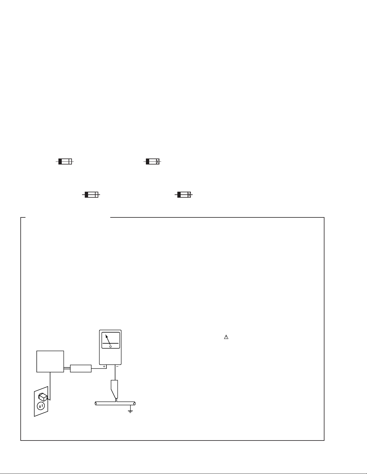
(FOR USA MODEL ONLY)
1. SAFETY PRECAUTIONS
The following check should be performed for the
continued protection of the customer and service
technician.
LEAKAGE CURRENT CHECK
Measure leakage current to a known earth ground (water
pipe, conduit, etc.) by connecting a leakage current tester
such as Simpson Model 229-2 or equivalent between the
earth ground and all exposed metal parts of the appliance
(input/output terminals, screwheads, metal overlays, control
shaft, etc.). Plug the AC line cord of the appliance directly
into a 120V AC 60Hz outlet and turn the AC power switch
on. Any current measured must not exceed 0.5mA.
Reading should
not be above
0.5mA
Earth
ground
Device
under
test
Also test with
plug reversed
(Using AC adapter
plug as required)
Leakage
current
tester
Test all
exposed metal
surfaces
ANY MEASUREMENTS NOT WITHIN THE LIMITS
OUTLINED ABOVE ARE INDICATIVE OF A POTENTIAL
SHOCK HAZARD AND MUST BE CORRECTED BEFORE
RETURNING THE APPLIANCE TO THE CUSTOMER.
2. PRODUCT SAFETY NOTICE
Many electrical and mechanical parts in the appliance
have special safety related characteristics. These are
often not evident from visual inspection nor the protection
afforded by them necessarily can be obtained by using
replacement components rated for voltage, wattage, etc.
Replacement parts which have these special safety
characteristics are identified in this Service Manual.
Electrical components having such features are identified
by marking with a
in this Service Manual.
The use of a substitute replacement component which does
not have the same safety characteristics as the PIONEER
recommended replacement one, shown in the parts list in
this Service Manual, may create shock, fire, or other hazards.
Product Safety is continuously under review and new
instructions are issued from time to time. For the latest
information, always consult the current PIONEER Service
Manual. A subscription to, or additional copies of, PIONEER
Service Manual may be obtained at a nominal charge from
PIONEER.
on the schematics and on the parts list
AC Leakage Test
2
Page 3
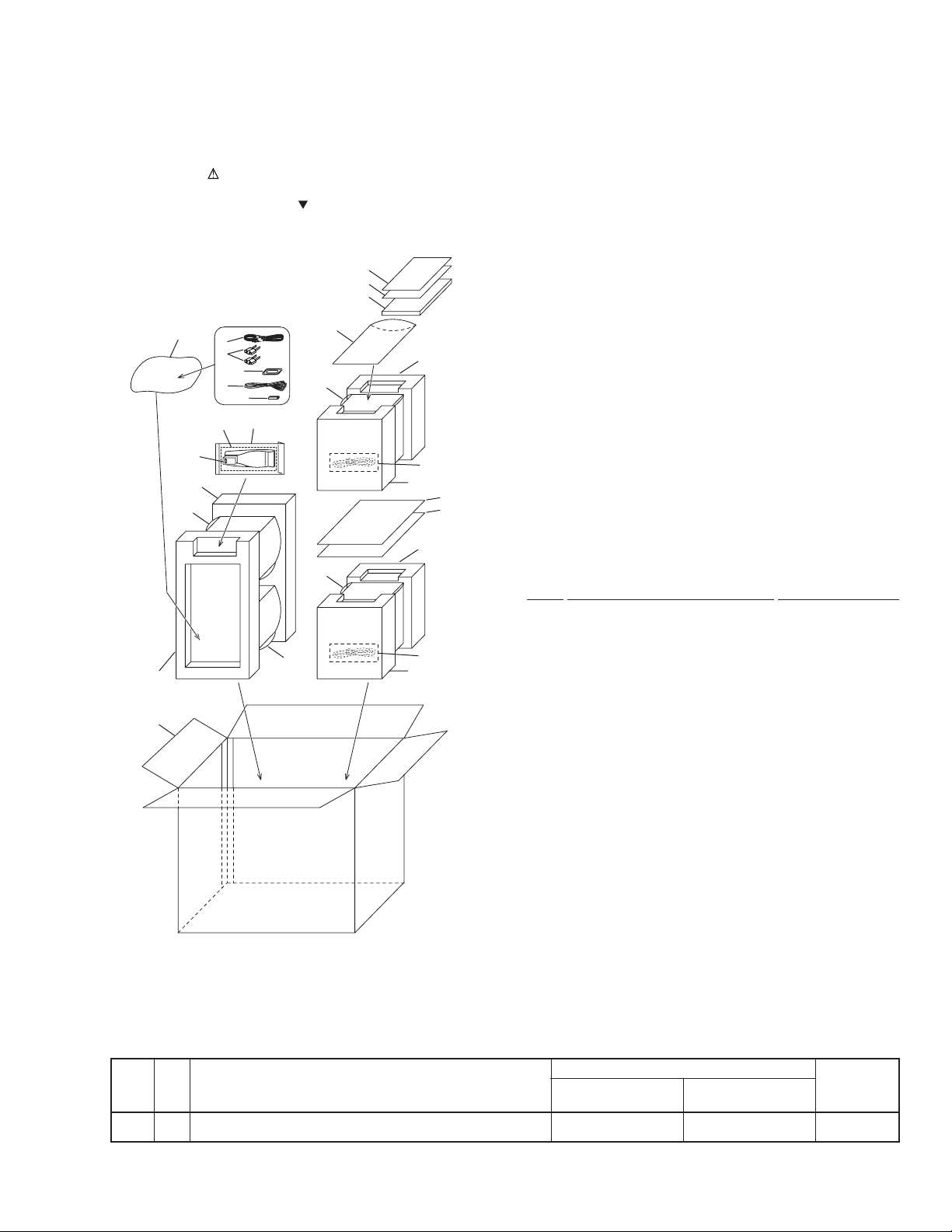
2. EXPLODED VIEWS AND PARTS LIST
NOTES:• Parts marked by "NSP" are generally unavailable because they are not in our Master Spare Parts List.
2.1 PACKING (X-LA21)
The mark found on some component parts indicates the importance of the safety factor of the part.
•
Therefore, when replacing, be sure to use parts of identical designation.
Screws adjacent to mark on the product are used for disassembly.
•
20DDXCN/AR Only
19
16
M-LA21
9(1/2)
17
14
9(2/2)
10
3
6
5
2
7
SPEAKER
SYSTEM
TOP SIDETOP SIDE
1
4
13
FRONTFRONT
FRONTFRONT
10
11
11
15
XC-LA21
REAR
M-LA21
REAR
8(2/2)
12
12
8(1/2)
8(2/2)
12
8(1/2)
18
18
(1) PACKING PARTS LIST
Mark No. Description Part No.
1 AM Loop Antenna ANT-PMT1E-AL
2 Remote Control Unit AXD7289
3 RCA Audio Cable 122003220100
NSP 4 ‘AAA’ Size R03 Batteries 130115004000
5 FM Wire Antenna 132030001001
6 Power-cord Plug Conversion Adaptor
138011722000
7 Battery Door 500RC4603070
8 Polyform Unit 800PMT190001
9 Polyfoam (Speaker) 800PMT390000
10 Poly Foam Sheet (C) SP 801999000002
NSP 12 PE Polybag (AC Cord) 805032115000
11 Polythenefoam Sheet 801999000005
NSP 13 PE Polybag (Remocon) 805035105000
NSP 14 PE Polybag (Antenna) 805070100000
NSP 15 PE Polybag (I Book) 805085140000
16 Operating Instructions 811PMT391011
(English/Spanish/Chinese)
17 Carton See Contrast table (2)
18 Corrugate Card 815001405213
19 Additional Sheet 810PMT395010
20 Correction Sheet See Contrast table (2)
(2) CONTRAST TABLE
X-LA21/DBDXCN and DDXCN/AR are constructed the same except for the following :
Part No.
Mark No. Symbol and Description X-LA21 X-LA21 Remarks
/DBDXCN /DDXCN/AR
17 Carton 813PMT393020 813PMT393010
20 Correction Sheet Not used 810PMT395020
3
Page 4
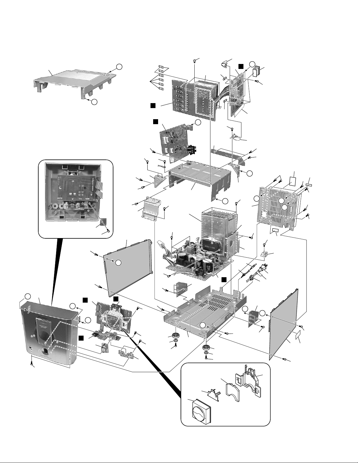
M-LA21
2.2 EXTERIOR SECTION
22
51
B
18
15
14
16
27
C
C
3
29
49
H
53
53
53
39
55
52
52
53
10
G
53
E
5
H
F
G
7
28
30
G
6
F
53
34
53
36
52
53
52
B
53
53
2
17
D
4
53
53
50
53
54
44
53
40
32
35
38
D
E
9
44
53
54
21
49
E
A
1
36
43
53
42
25
A
53
20
33(×3)
12
13
A
D
50
37
53
53
53
49
57
45
DDXCN/AR
Only
F
23
52
B
C
56
DDXCN/AR
Only
26
19
47
52
31
46
DBDXCN
Only
53
48
52
52
53
52
24
11
4
Page 5
M-LA21
(1) EXTERIOR SECTION PARTS LIST
Mark No. Description Part No. Mark No. Description Part No.
2 TRANSFORMER Assy PMT1LA100031
1 AMP Assy PMT1LA100011
3 PRIMARY Assy PMT1LA100041
4 JACK Assy PMT1LA100021
5 POWER METER Assy PMT1LA100081
6 LED Assy PMT1LA100051
7 HP JACK Assy PMT1LA100111
8 • • • • •
NSP 9 PROTECTION PCB PMT1LA100141
10 S-Assy PMT3 FP01 SUBPMT3AMFP
11 Meter Assy SUBPMT3MTR
NSP 12 Heat Sink Board 033PMT1LS100
13 DC Cord 122006020060
14 Transformer (TR701) 1236C0250140
15 Fuse 124010020001
(F322, F323 : T1AL/250V)
16 Fuse 124025020001
(F328, F329 : T2.5A/250V)
17 Fuse (F321 : T3.15A/250V) 124031520003
18 Fuse 124063020001
(F324-F327 : T6.3AL/250V)
19 AC Cord See Contrast table (2)
20 Back Cover See Contrast table (2)
21 Diffuser Lens 500PMT309000
22 Top Panel 500PMT311001
23 Meter Holder 505PMT307000
24 Lens Holder 505PMT308000
25 Rectifier PCB Bracket 505PMT370000
26 PCB Bracket-R 505PMT372000
27 Mounting Bracket 505266422000
28 Power Knob 510PMT312001
29 Voltage Selector Knob 510PMT319000
30 Side Panel-L 600PMT117002
31 Side Panel-R 600PMT118002
NSP 32 Bottom Tray 600PMT302000
33 Copper Post 603PMT381000
34 Power Switch Bracket 605PMT313000
35 Transformer Bracket 605PMT317000
36 Mounting Bracket-1 605PMT373000
37 Mounting Bracket-2 605PMT374000
38 Mounting Bracket-3 605PMT375000
39 Mounting Bracket-4 605PMT376000
40 • • • • •
41 Heat Sink CDG-74 6130CDG74000
42 PCB Sheet 650PMT377000
43 Bushing 700PMT156000
44 Rubber Foot 700PMT384000
45 Strain Relief Bushing 700036022000
46 EMC Label See Contrast table (2)
47 Back Label See Contrast table (2)
NSP 48 Serial Label 809000009000
49 Screw BBZ30P100FNI
50 Screw BBZ30P180FMC
51 Screw BBZ40P060FMC
52 Screw BPZ30P100FNI
53 Screw KBZ30P060FNI
54 Foot Stand 509PMT329000
55 Holding PCB PMT1LA-100-121
56 Caution Label See Contrast table (2)
57 AC Cord Label See Contrast table (2)
(2) CONTRAST TABLE
M-LA21/DBDXCN and DDXCN/AR are constructed the same except for the following :
Part No.
Mark No. Symbol and Description M-LA21 M-LA21 Remarks
/DBDXCN /DDXCN/AR
19 AC Cord 134250220000 134220120016
20 Back Cover 500PMT303000 500PMT388000
46 EMC Label 809PMT394030 Not used
47 Back Label 809PMT396040 809PMT396060
56 Caution Label Not used 809PMT394070
57 AC Cord Label Not used 809PMT394100
5
Page 6
1
M-LA21
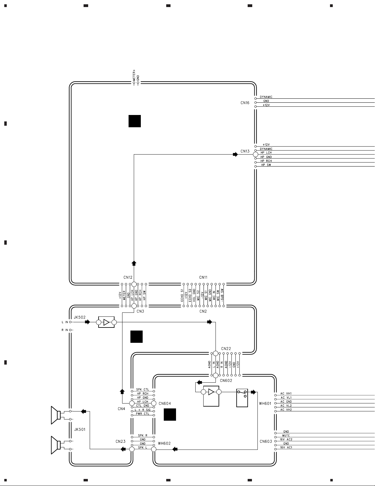
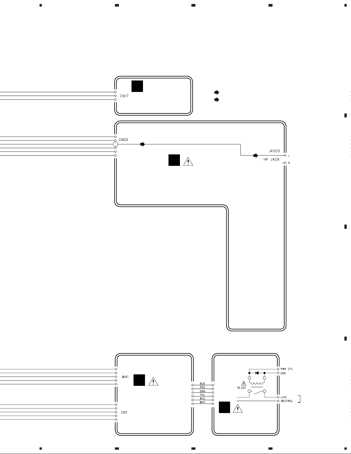
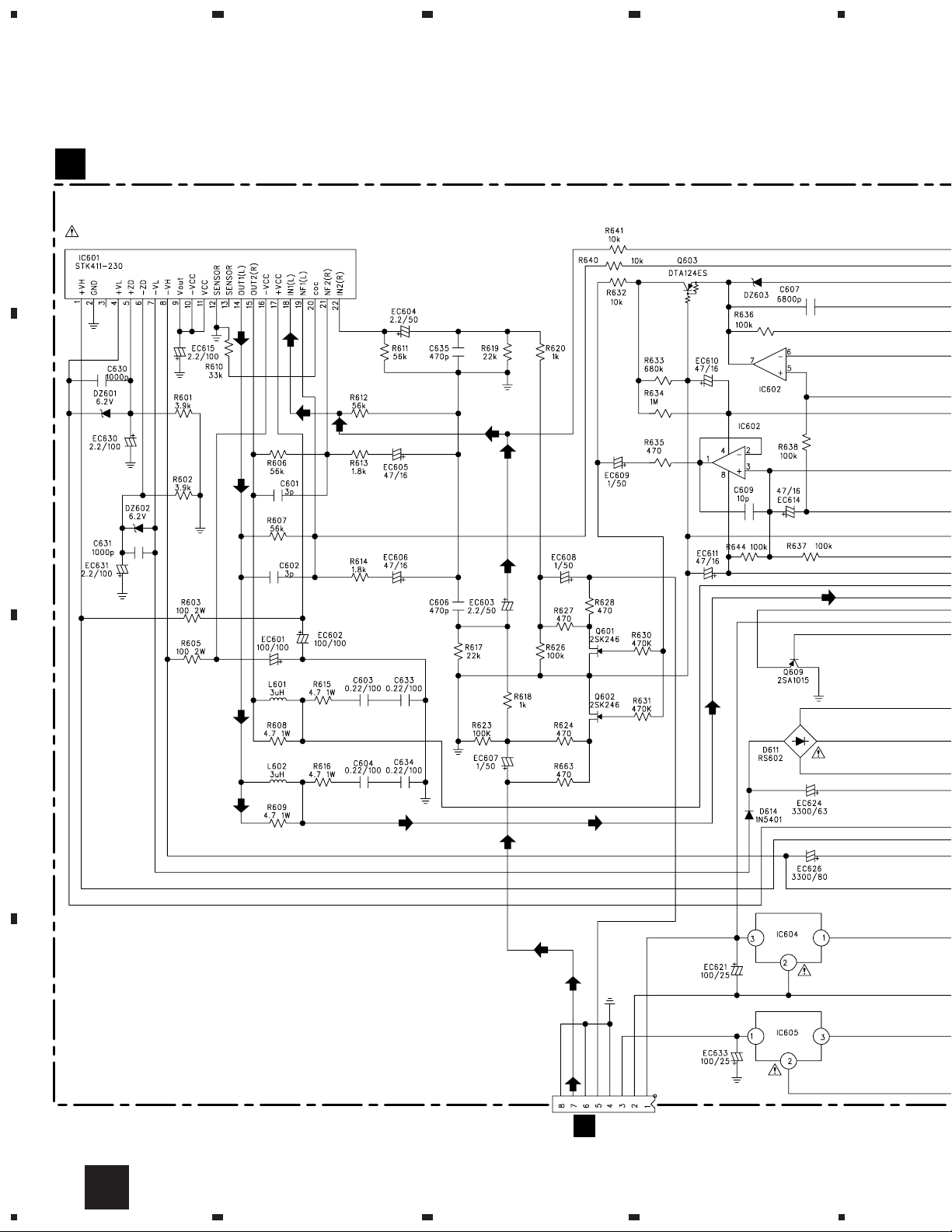
3. SCHEMATIC DIAGRAM
A
3.1 OVERALL WIRING DIAGRAM
B
23
E
POWER METER ASSY
(PMT1LA100081)
(PH)
3
4
(PH)
4
C
From
XC-LA21
SPEAKER
OUT
L
D
5 7
IC504
BA4558N
(PH)
4
JACK ASSY
D
(PMT1LA100021)
4 4
A
7
7
18 14
IC601
STK411-230
POWER AMPLIFIER
RL601
PLY-DPDT
AMP ASSY
(PMT1LA100011)
R
4 4
6
1234
Page 7
5
678
M-LA21
Note : When ordering service parts, be sure to refer to "EXPLODED VIEWS and PARTS LIST" or "PCB PARTS LIST".
A
F
LED ASSY
(PMT1LA100051)
3
(PH)
(PH)
G
HP JACK ASSY
(PMT1LA100111)
: AUDIO SIGNAL ROUTE
: AUDIO SIGNAL ROUTE (PHONES)
(PH)
PHONES
B
C
D311
From
XC-LA21
B
TRANSFORMER
ASSY
(PMT1LA100031)
C
AC IN
PRIMAY ASSY
(PMT1LA100041)
5
6
7
8
D
7
Page 8
1
23
M-LA21
3.2 AMP, TRANSFORMER and PRIMARY ASSYS
4
A
B
AMP ASSY (PMT1LA100011)
A
010-550411-000A
MTZJ6.2A
MTZJ6.2A
003-030840-050
003-030840-050
2/2
BA4558DX
BA4558DX
1/2
018-030036-300A
004-022410-100
C
D
018-030036-300A
004-022410-100
CN602
136-08PMT3-200J
011-020602-001A
006-033200-63D
011-025401-000A
006-033200-80D
NJM78M12FA
NJM79M12FA
CN22
D
8
A
1234
Page 9

5
678
M-LA21
: AUDIO SIGNAL ROUTE (L ch)
D
CN4
HP
HP
HP
CN604
136-07PMT3-202J
: AUDIO SIGNAL ROUTE (PHONES)
A
BA4558DX
011-024001-000A
006-033200-63D
011-025401-000A
2/2
1/2
BA4558DX
WH601
136-05PMT3-350J
CN603
136-06PMT3-200J
BZ605
MTZJ3.0A
BZ604
MTZJ3.0A
WH1
025-230041-000A
124063020001
124010020001
CN1
135-PHS060-060J
HP
TRANSFORMER ASSY
B
(PMT1LA100031)
1236C0250140
010-024001-000A
025-230041-000A
124025020001
128-1221125-000
Q610 DTA114YS
008-801144-000A
Q617 DTA114YS
008-801144-000A
122006020060
WH602
136-04PMT3-350J
CN23
D
B
C
006-033200-80D
011-020602-001A
011-020005-000A
011-020005-000A
011-020005-000A
011-020005-000A
• NOTE FOR FUSE REPLACEMENT
CAUTION -
FOR CONTINUED PROTECTION AGAINST RISK OF FIRE.
REPLACE WITH SAME TYPE AND RATINGS ONLY.
5
CN8
6
135-PHS020-020J
128-090109-000A
D311
011-024001-000A
PRIMARY ASSY (PMT1LA100041)
C
124025020001
137-400001-000J
NEUTRAL
AC IN
AC CORD
124031520003
LIVE
124250220000
D
CBA
7
8
9
Page 10

1
23
M-LA21
3.3 JACK, POWER METER, LED and HP JACK ASSYS
A
JACK ASSY (PMT1LA100021)
D
004-056210-100
4
135-053259-040J
CN23
B
WH602
004-033210-100
IC504
BA4558DX
A
JK501
118-000134-003J
LR
AUDIO IN
JK502
118-020202-0001J
C
004-056210-100
MTZJ12B
IC502
BA4558DX
1/2
MTZJ9.1C
D
10
D
1234
Page 11

5
678
M-LA21
A
: AUDIO SIGNAL ROUTE (L ch)
HP
: AUDIO SIGNAL ROUTE (PHONES)
E
POWER METER ASSY
(PMT1LA100081)
CN11
136-11PMT3-200J
CN2
135-PHS110-110J
B
2/2
IC502
BA4558DX
CN22
135-PHS080-080J
CN3
HP
HP
HP
A
CN602
CN12
136-17PMT3-200J
135-PHS070-070J
CN604
A
CN4
CN16
135-030060-200J
CN13
050-060060-200J
G
HP JACK ASSY
(PMT1LA100111)
CN20
135-053259-040J
110-033040-013A
CN17
110-033162-003A
HP JACK ASSY
SW501 : DYNAMIC
JK503
116-008020-000
HPHPHPHP
021-022322-000A
C
PHONES
LED ASSY
F
135-PHS070-070J
5
6
(PMT1LA100051)
7
D
GFED
8
11
Page 12

1
23
M-LA21
4. PCB CONNECTION DIAGRAM
A
4.1 AMP ASSY
NOTE FOR PCB DIAGRAMS :
• Part numbers in PCB diagrams match those in the schematic
diagrams.
• The parts mounted on this PCB include all necessary parts for
several destinations.
For further information for respective destinations, be sure to
check with the schematic diagram.
• View point of PCB diagrams.
B
WH1
AMP ASSY
A
ACVL1
WH601
ACVH1
RED
W601
WHT
ACVL2
ACGND
BLU
BLK
4
ACVH2
EC625
ORN
Z1
R670
E
Q617
Z2
Connector
B
P.C.Board
C
Capacitor
Chip Part
SIDE A
SIDE B
B
CN1
16VAC1
GND
16VAC2
MUTE
CTLGND
PWRCTL
C619
CN603
BLK
BRN
RED
ORN
YEL
WHT
EC623
W604
D608
P2
D612 D611
D610
W603
D609
W602
EC620
P3
EC624
R305
D607
EC622
W605
E
IC604
IC605
E
EC621
EC633
D
W606
C618
W607
EC626
Q617
SIDE A
12
A
1234
Page 13

5
678
M-LA21
EC620
P3
EC624
C622
EC626
Z1
W602
R669
Q609
R668
R621
P1
D606
W633
R667
EC614
EC618
W610
E
C603
C604
D614
W609
R672
Q616
W613
W611
BLK
E
R639
Q606
E
R635
Q610
Q607
E
E
Q605
C633
W635
C609
E
R671
W614
R625
W625
IC603
D613
DZ605
EC619
C637
R681
EC616
EC609
EC611
C607
DZ604
R629
R632
PMT1LA-01-01 AMP BOARD
EC617
W612
E
R651
Q611
Q615
E
DZ603
C608
D616
R650
R636
Q608
R657
W640
E
Q613
E
BLK.
D601
R642
E
C634
R644
E
Q603
R634
R652
R654
R653
C636
R604
Q604
R658
R662
D602
R645
R633
R638
D604
E
Q614
D615
EC613
C610
E
Q612
R630
R631
R637
R643
W626
EC610
R656
L601
R648
R647
R649
R646
R615
R616
W627
W628
C612
R641
R665
W616
W639
EC605
W634
W617
IC602
R664
R608
EC606
W629
Q602
D
RL601
W618
R609
E
R640
CN23
W619
R603
R614
C606
EC607
R663
C611
SPKR
ORN
GND
BLK
SPKL
BLK
GND
RED
R617
W630
R623
EC612
L602
EC601
C601
R618
Q601
R624
WH602
CTL GND
PWRCTL
EC630
EC631
C631
C602
E
CN602
SPKCTL
HPRCH
HPGND
HPLCH
L+R SIG
DZ602
EC602
EC615
R607
R606
R613
W638
C635
R626
R628
AGND
LIN
AGND
RIN
AGND
-12V
GND
+12V
D
R622
CN604
DZ601
C630
W623
R619
WHT
WHT
WHT
WHT
WHT
WHT
RED
R602
R605
R612
EC603
CN4
R661
W620
W621
W622
W624
R627
R601
R611
"BOND"
R659
R610
EC604
R620
EC608
A
IC601
B
C
W637
D
Q617
Q610
Q607 Q615 Q604
Q606 Q605
IC603
5
Q608
Q611 Q613 Q614 Q612
6
Q602 Q601 IC601Q609Q616
IC602Q603
7
D
CN22
A
8
13
Page 14

1
23
M-LA21
4.2 TRANSFORMER and PRIMARY ASSYS
A
PRIMARY ASSY
C
B
F329
4
J2
J1
F328F329
BLK
F328
RED
ORN
YEL
PRIMARY
BLU
DANGER
D311
RL301
C315
BRN
CN9
CN8
MUTE
CTLGND
PWR
GND.
PWRCTL
PMT1LA-01-04
SW301
PRIMARY BOARD
R308
LN
C
"BOND"
C321
L301
NL
C316
F321
F321
NEUTRAL
D
SIDE A
LIVE
AC IN
14
C
1234
Page 15

5
TRANSFORMER ASSY
B
PRIMARY DANGER
CN10
BLK
RED
ORN
YEL
BLU
BRN
678
M-LA21
A
PMT1LA-01-03
TRANSFORMER BOARD
PT1
F322
F325
ACVH1
RED
WHT
ACVL1
ACGND
BLK
ACVL2
BLU
ORN
ACVH2
F327
PWRCTL
GND
MUTE
16VAC2
GND
16VAC1
F323
F324
WH1
CN1
BLK
CN603
A
WH601
A
B
F326
SIDE A
C
D
B
5
6
7
8
15
Page 16

1
M-LA21
4.3 JACK ASSY
A
D
JACK ASSY
23
4
CN11
E
R577
+12V
-12V
R589
CN2
J59
+12V
J78
AGND
-12V
J80
AGND
RCHOUT
AGND
LCHOUT
AGND
J81
J61
J83
CN3
+12V
METER
GND
HPLCH
HPGND
HPRCH
HPSW
B
ECHOSIG1
ECHOSIG2
VOLGND
MICSIG2
MICSIG1
MICGND
MICIN
MICSW
-6dB SW
C
E
CN12
CN604
A
R590
R597
EC562
CN22
CN602
A
EC561
R555
Q511
Q515
EC546
J564
EC531
J74
J563
R503
C549
R571
PWRCTL
METERIN
GND
HPLCH
HPGND
HPRCH
HPSW
R506
R504
R505
Q517
CN4
JACK BOARD
PMT1LA-01-02
CN23
EC559
EC560
EC537
EC548
Q518
R575
R599
C547
R561
R507
C548
R502
R576
EC541
GND
SPKL
GND
SPKR
FOR NON-KARAOKE
C529
R558
R501
R530
R529
J39
EC535
R598
R567
R593
IC504
R580
R596
C535
Q514
C539
R579
Q501
R592
EC532
EC545
Q504
EC544
R594
R552
D509
R572
Q516
C543
R560
C546
J71
C541
EC536
R520
Q513
J82
Q512
R557
R591
R551
DZ506
R545
DZ504
C519
J40
C532
J52
EC529
R554
EC549
EC523
EC521
C516
C533
C528
C531
D506
R548
EC528
R547
C518
D510
R553
IC502
EC530
EC522
D511
R581
R542
C517
TO EC522
EC527
C524
W1
C530
C525
Q502
DZ505
R584
EC526
R523
R522
R550
Q503
Z2
TO EC523
EC520
R521
J29
R549
C558
EC525
EC524
J54
Z1
C520
IC512
EC511
MSSOP36-P-450-0.A
EC515
EC514
R570
R569
EC533
EC534
J68
C557
R533
R534
EC513
R585
EC517
EC512
R586
R532
C523
"BOND"
C544
"BOND"
RIN
R588
C556
R587
J67
C545
EC518
R518
LIN
JK502
JK501
"BOND"
"BOND"
SIDE A
WH602
A
Q511
Q515
Q518
Q517
Q512
IC504
Q513
Q501 Q502
IC502
D
16
D
1234
IC512Q516 Q514
Q503Q504
Page 17

1
234
4.4 POWER METER, LED and HP JACK ASSYS
LED ASSY
F
LED503
R574
POWER
E
R573
+12v
METER
ASSY
GND
LED501
DYNA
MIC
M-LA21
A
PMT1LA-01-05
LED502
CN17
PMT1LA-01-05
D
CN2
D
CN3
CN11
CN12
JK503
ECHOS1
+12V
ECHOS2
VOLGND
MICS2
-12V
MICS1
MIC GND
MIC
MIC SW
DYNAMIC
+12V
METER
LED GND
HP Lch
HP GND
HP Rch
HP SW
CN20
HP SW
HPSW
HP GND
HP Rch
HPRCH
DYNAMIC
HP Lch
HPLCH
HPGND
+12V
CN13
+12V
DYNAMIC
C551
CN14
EC557
W552
MIC GND
+12V
MIC GND
CN19
EC556
MIC
+12V
R568
-12V
MIC
R565
MIC SW
-12V
MIC SW
EC555
R564
JK504
W1
W2
W3
W4
W5
W6
W554
CN16
DYNAMIC
GND
+12v
MMETER
EC558
IC506
SW501
HP JACK ASSY
G
PMT1LA-01-11
PMT1LA-01-11
PMT1LA-01-08
PMT1LA-01-08
ECHOS1
ECHOS2
VOLGND
+12V
MICS2
-12V
MICS1
CN15
SIDE A
B
C
D
GFE
1
2
3
4
17
Page 18

M-LA21
Mark No. Description Part No.
Mark No. Description Part No.
5. PCB PARTS LIST
NOTES:•Parts marked by "NSP" are generally unavailable because they are not in our Master Spare Parts List.
The mark found on some component parts indicates the importance of the safety factor of the part.
•
Therefore, when replacing, be sure to use parts of identical designation.
When ordering resistors, first convert resistance values into code form as shown in the following examples.
•
Ex.1 When there are 2 effective digits (any digit apart from 0), such as 560 ohm and 47k ohm (tolerance is shown by J=5%,
and K=10%).
560 Ω→56 × 10
47k Ω→47 × 103→ 473 ........................................................RD1/4PU 4 7 3 J
0.5 Ω→R50 .....................................................................................RN2H
1 Ω→1R0 .....................................................................................RS1P
Ex.2 When there are 3 effective digits (such as in high precision metal film resistors).
5.62k Ω→ 562 × 10
Mark No. Description Part No.
LIST OF ASSEMBLIES
AMP ASSY PMT1LA100011
TRANSFORMER ASSY PMT1LA100031
PRIMARY ASSY PMT1LA100041
JACK SSY PMT1LA100021
POWER METER AASSY PMT1LA100081
LED ASSY PMT1LA100051
HP JACK ASSY PMT1LA100111
1
→ 561 ........................................................RD1/4PU 5 6 1 J
R 5 0
1 R 0
1
→ 5621 ......................................................RN1/4PC 5 6 2 1 F
Mark No. Description Part No.
C618,C619 CKCYB103K50
C630,C631 CKCYB102K50
C636,C637 CKCYB101K50
C601,C602 CCCCH030D50
EC607-EC609,EC618 CEAT1R0M50
EC615,EC630,EC631 CEAT2R2M2A
EC603,EC604 CEAT2R2M50
EC619 CEAT100M50
EC601,EC602 CEAT101M2A
EC621,EC633 CEAT101M25
K
K
AMP ASSY
A
SEMICONDUCTORS
IC601 (STK411-230) 010-550411-000A
IC604 NJM78M12FA
IC605 NJM79M12FA
D604,D606 (RECTIFIER IN-4001B) 011-024001-000A
D607-D610 (RECTIFIER J-05) 011-020005-000A
D611,D612 (BRIDGE RECTIFIER) 011-020602-001A
IC602,IC603 BA4558DX
Q601,Q602 2SK246
Q603 DTA124ES
Q605-Q608,Q616 2SC1815
Q611-Q614 2SD1468S
Q604,Q609,Q615 2SA1015
Q610,Q617 (DTA114YS) 008-801144-000A
D602,D616 1N4148
D614,D615 (RECTIFIER IN-5401BL) 011-025401-000A
BZ604,BZ605 MTZJ3.0A
DZ601,DZ602 MTZJ6.2A
COILS
L601,L602 (3µH) 018-030036-300A
RELAY
RL601 (12V OSA-SS-212DM5) 128-122125-000A
CAPACITORS
C603,C604,C633,C634 004-022410-100
(MYLAR CAP 0.22 uF/100V)
C606,C635 CKCYB471K50
C607,C610 CKCYB682K50
C608,C609,C611,C612 CCCCH100D50
EC616 CEAT221M16
EC617 CEAT331M10
EC620,EC624 (ELECT3300µF/63V) 006-033200-63D
EC625,EC626 (ELECT3300µF/80V) 006-033200-80D
EC605,EC606,EC610-EC614 CEAT470M16
EC622,EC623 CEAT471M25
RESISTORS
R603,R605 RS2LMF101J
R608,R609,R615,R616 RS1LMF4R7J
R652,R654 RS3LMFR22J
R664,R665 RS1LMF681J
Other Resistors RD1/4PU J
OTHERS
CN602 HSG PMT3-8A JST PHR- 136-08PMT3-200J
CN604 HSG PMT3-7C JST PHR- 136-07PMT3-202J
WH602 HSG MOLEX 51067-0400 136-04PMT3-350J
WH601 HSG MOLEX 51067-0500 136-05PMT3-350J
CN603 HSG PMT3-6A JST PHR- 136-06PMT3-200J
JP WIRE AWG22 80MM B 051-275080-009J
JP WIRE AWG26 80MM B 051-675080-009J
TRANSFORMER ASSY
B
ROUND PIN 137-500001-000J
OTHERS
CN1 HEADER CTL 6 PINS 135-PHS060-060J
WH1 HEADER MOLEX 5 PINS 135-053258-050J
FUSE HOLDER 7900,HT 550-790000-000J
18
Page 19

M-LA21
Mark No. Description Part No.
PRIMARY ASSY
C
SEMICONDUCTOR
D311 (RECTIFIER IN-4001B) 011-024001-000A
RELAY • SWITCH
RL301 (RELAY 9 OSA-SS-212DM) 128-090109-000A
SW301 (SLIDE SW VOLT.SELECTOR) 025-230041-000A
CAPACITORS
C315,C321 (CERAMIC CAP 0.01µF) 003-010320-250A
OTHERS
CN8 HEADER CTL 2 PINS 135-PHS020-020J
JACK ASSY
D
JP WIRE AWG22 BROWN 054-010150-010J
JP WIRE AWG22 ORANGE 054-010150-030J
JP WIRE AWG22 BLUE 054-010150-050J
JP WIRE AWG22 RED 054-010150-061J
JP WIRE AWG22 BLACK 054-010150-093J
JP WIRE AWG22 YELLOW 054-010150-100J
AC CONTACT TERMINAL 137-400001-000J
FUSE HOLDER 7900,HT 550-790000-000J
SEMICONDUCTORS
IC502,IC504 BA4558DX
Q502,Q515 DTA124ES
Q501,Q503,Q513 DTC124ES
Q504 2SA1015
Q511 DTC114ES
Mark No. Description Part No.
JP WIRE AWG26 50MM R 051-675050-006J
CN23 HEDER MOLEX 4PINS 53 135-053259-040J
POWER METER ASSY
E
JP WIRE AWG26 50MM B 051-675050-009J
OTHERS
CN11 HSG PMT3-11A JST 136-11PMT3-200J
CN12 HSG PMT3-7A JST 136-07PMT3-200J
CN13 CONN PIN 6 PINS 050-060060-200J
CN16 CONN PIN 3 PINS 050-030060-200J
LED ASSY
F
SEMICONDUCTORS
LED502,LED503 (LED-R-3MM&-S-STP)110-033040-013A
LED501 (LED-BL-3MM&-S-&&&) 110-033162-003A
RESISTORS
All Resistors RD1/4PU J
HP JACK ASSY
G
SWITCH
SW501 (PUSH BOTTON SWICH 2P2T) 021-022322-000A
OTHERS
JK503 HEADPHONE JACK ST 116-008020-000
Q512 2SC1815
Q516-Q518 2SK246
D506,D509,D510,D511 1N4148
DZ504 MTZJ9.0C
DZ505 MTZJ12B
CAPACITORS
C541,C543 CKCYB101K50
C539,C546 CKCYF103Z50
C547,C548 (MYLAR CAP 5600pF) 004-056210-100
C549 (MYLAR CAP 3300pF) 004-033210-100
C556,C557 CKCYB102K50
C533,C558 CGCYF104Z25
EC544,EC545 CEJQ2R2M50
EC532,EC548 CEJQ101M16
EC535,EC536 CEJQ220M16
EC561,EC562 CEJQ470M16
EC531,EC533,EC534,EC537 CEJQ100M16
EC546,EC559,EC560 CEJQ100M16
EC529,EC530,EC541 CEJQ1R0M50
RESISTORS
All Resistors RD1/4PU J
OTHERS
CN3,CN4 HEADER CTL 7 PINS 135-PHS070-070J
CN22 HEADER CTL 8 PINS 135-PHS080-080J
CN2 HEADER CTL 11 PINS 135-PHS110-110J
JK501 PUSH TERMINAL BOARD 118-000134-003J
JK502 PIN JACK BOARD 118-020202-001J
6. ADJUSTMENT
There is no information to be shown in this chapter.
19
Page 20

M-LA21
7. GENERAL INFORMATION
7.1 DIAGNOSIS
7.1.1 SINGLE OPERATION METHOD
Please supply +9V from DC power supply to the following point.
PRIMARY ASSY
C
J2
J1
F329
F328F329
BLK
F328
RED
ORN
SW301
C321
PRIMARY
DANGER
PMT1LA-01-04
PRIMARY BOARD
NL
"BOND"
L301
C316
R308
F321
LN
F321
D311
RL301
C315
YEL
BLU
BRN
CN9
CN8
MUTE
CTLGND
PWR
GND.
PWRCTL
DC power supply
DC+9V
GND
20
Page 21

7.1.2 DISASSEMBLY
× 2
1
M-LA21
× 2
× 2
× 2
1
× 2
1
10
10
10
× 2
Side Panel L
(Remove it as Side Panel R in the same way.)
2
Slide the Side Panel R
toward the rear, then
Side Panel R
Top Panel
Unhook
remove it.
× 2
× 2
1
Front Panel
3
7
10
× 2
8
10
9
Mounting Bracket-4
11
× 2
8
Mounting
Bracket
× 4
12
Remove it of
R side in the
same way.
15
Remove a Strain
Relief.
16
5
× 2
4
Disconnect a
Connector (CN8).
5
Unhook
× 2
13
13
× 4
14
13
5
× 2
6
Unhook
21
Page 22

M-LA21
17
F
LED Assy
18
19
Diagnosis
D
JACK Assy
Transformer Bracket
17
22
POWER METER Assy
E
HP JACK Assy
G
B
TRANSFORMER Assy
PRIMARY Assy
C
AMP Assy
A
Page 23

8. PANEL FACILITIES AND SPECIFICATIONS
8.1 PANEL FACILITIES
Front Panel
M-LA21
1
DYNAMIC MODE
HIGH EFFICIENT
AMPLIFIER
POWER OUTPUT
DINAMIC
— OFF _ ON
LA21
STEREO POWER AMPLIFIER
2
3
4
1 PHONES socket – Plug in a pair of headphones
for private listening.
2 DYNAMIC MODE indicator – Lights when the
DYNAMIC is switched on.
3 POWER OUTPUT meter – Shows the output level
of the currently selected source.
4 DYNAMIC – Switch on for extra power in the bass
and a richer treble.
23
Page 24

M-LA21
8.2 SPECIFICATIONS
Power Section & Miscellaneous
Power Requirements
............................ AC 110-127/220-230/240 V (switchable),
50/60 Hz
Power Consumption (ON mode)
(Total including XC-LA21)........................... 538 W
Power Consumption (Standby mode) ............................ 1 W
Dimensions
Stereo power amplifier ......... 160(W) x 176(H) x 315(D) mm
Weight
Stereo power amplifier ................................................5.1 kg
NOTE: Specifications and design subject to possible
modification without notice, due to improvements.
24
 Loading...