

Page 1
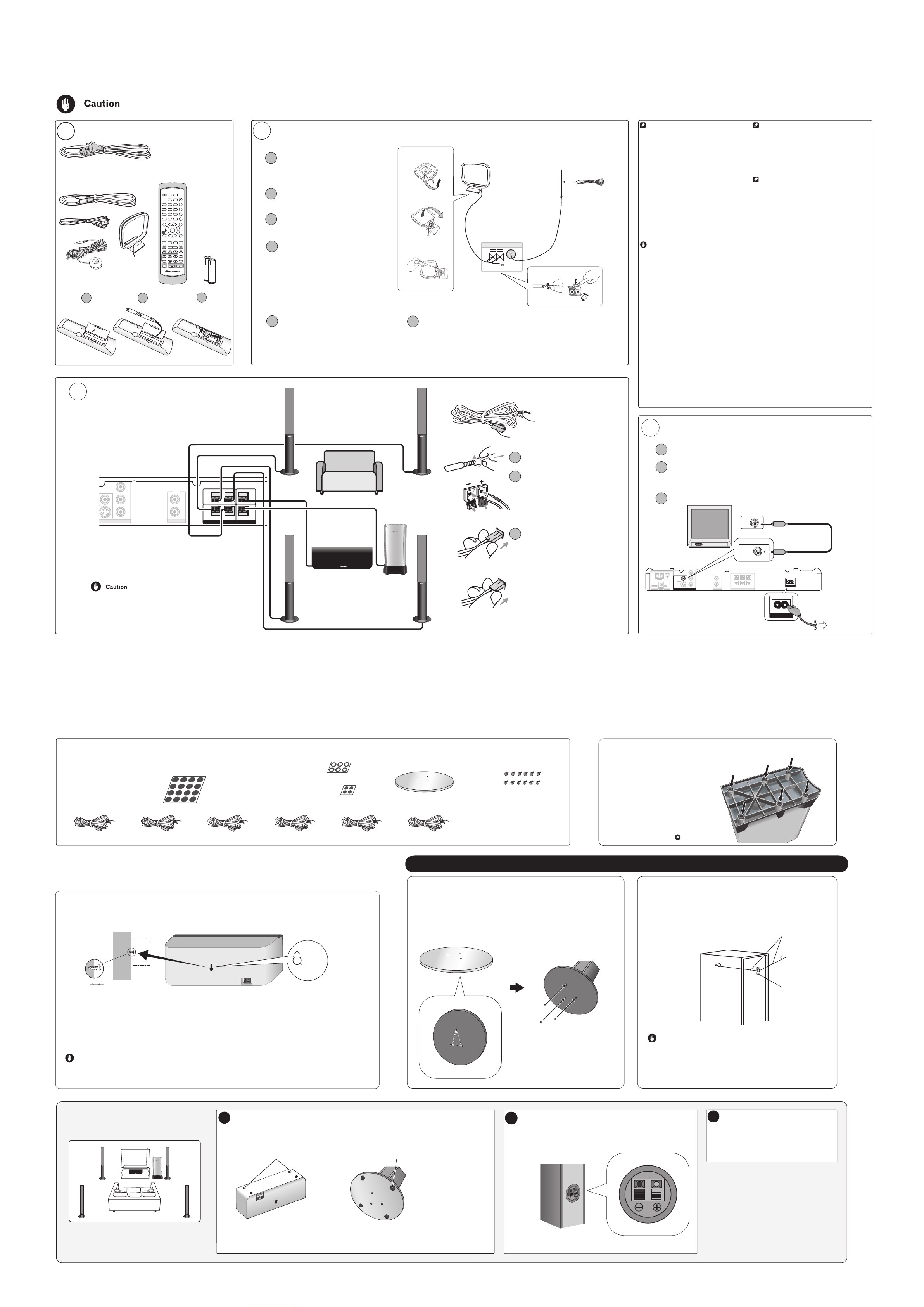
Setting up your DVD/CD Receiver
V
When connecting this system or changing connections, be sure to switch the power off with the STANDBY/ON button, and disconnect the power cord from the AC outlet.
Do not use these speakers with any other system or amplifier as this may result in damage or fire.
Check that you have all the accessories, then put
1
the batteries in the remote control.
* In some countries or regions, the shape of the
power plug may sometimes differ from that
shown in the explanatory drawings.
FM antenna
Power cord *
Video cord
AM loop antenna
Remote control
TUNER
STANDBY
DVD/CD
(FM/AM)
/ON
OPEN/
CLOSE
USB
LINE
AUDIO
123
SUBTITLE
456
ANGLE
789
ZOOM
CLEAR
DISPLAY
0
TUNE
MENU
TOP MENU
SETUP
SRĸ
AA size IEC R6
ST
ST
ENTER
HOME
MENU
RETURN
dry cell batteries
MCACC
TUNE
TEST TONE
SOUND
RETRIEVER
SURROUND
ADVANCED
SOUND
(to confirm
system operation)
TV CONTROL
SLEEP
INPUT CHANNEL VOLUME
MUTE
SHIFT
VOLUME
Microphone
(for Auto MCACC setup)
1 2
Connect each speaker using the color-coded speaker cords.
3
Match them to the colored speaker terminals on the rear
panel of the DVD/CD receiver.
CR/
R
VIDEO
P
CB/
B
P
Y
LINE
L
R
AUDIO IN
COMPONENT
IDEO OUT
For the best surround sound, setup your speakers
as above. The front left and right speakers should
be about 1.8 m to 2.7 m apart.
These speaker terminals carry HAZARDOUS LIVE voltage. To prevent the risk of
electric shock when connecting or disconnecting the speaker cables, disconnect
the power cord before touching any uninsulated parts.
Connect the AM and FM antennas to the rear panel of the DVD/CD receiver.
2
Pull off the protective
1
fig. A
shields of both AM antenna
wires.
Push open the tabs, then insert
2
one wire fully into each terminal.
Release the tabs to secure the AM
3
fig. B
4
6
antenna wires.
AM LOOP
ANTENNA
FM
UNBAL 75Ω
1
3
2
Fix the AM loop antenna to the
4
attached stand.
fig. C
To fix the stand to the antenna, bend in the
direction indicated by the arrow (fig. A) then
clip the loop onto the stand (fig. B).
Note: If you plan to mount the AM antenna
to a wall or other surface, secure the stand
3
with screws (fig. C) before clipping the loop
to the stand. Make sure the reception is clear.
Place the AM antenna on a flat
5
surface and point in the direction
giving the best reception.
Don’t let it come into contact with metal
objects and avoid placing near computers,
television sets or other electrical appliances.
6
Connect the FM wire antenna to the FM UNBAL 75 Ω antenna terminal.
For best results, extend the FM antenna fully and fix to a wall or door
frame. Don’t drape loosely or leave coiled up.
Note:
The signal earth (H) is designed to reduce noise that occurs when an
antenna is connected. It is not an electrical safety earth.
Connect each speaker as shown below.
Color-coded wire
(Connect to speaker)
Twist and pull off the protective
1
shields on each wire.
Connect the wires to the
2
speaker. Match the colored
wire with the color-coded
label (above the tabs), then
FRONT
RL
Surround right
(Grey)
CENTER
Listening position
Surround left
(Blue)
Color-coded connector
(Connect to rear panel)
Using the remote control
The remote control can be used within a range of about 7
meters from the remote sensor on the front panel, and
within a 30 degree angle.
Precautions:
• The remote control may not work if there is an obstacle
between the remote control and the display unit, or if the
remote control is not directed towards the remote sensor
of the display unit at the correct angle.
• The remote control may not work properly if strong
light such as direct sunlight or fluorescent light is shining
onto the unit’s remote sensor.
• The remote control may not work properly when this
unit is used near devices emitting infrared rays, or when
remote controls of other devices which use infrared rays
are used. Also, the use of this remote control may cause
other devices to work improperly.
• When the operating range of the remote becomes too
short, replace the batteries.
Remote control battery caution
Incorrect use of batteries may cause leakage or
rupture.
Always be sure to follow these guidelines:
• Always insert batteries into the battery compartment
correctly matching the positive ª and negative ·
polarities, as shown by the display inside the
compartment.
• Never mix new and used batteries.
• Batteries of the same size may have different voltages,
depending on brand. Do not mix different brands of
batteries.
• When disposing of used batteries, please comply with
governmental regulations or environmental public
instruction's rules that apply in your country or area.
• In order to prevent battery leakage, remove the
batteries when not using the remote control for an
extended period (one month or more). If leakage occurs,
carefully wipe away any battery fluid inside the
compartment, and replace the batteries with new ones.
• Do not allow books or other objects to rest on top of
the remote control, since the buttons may be depressed,
causing faster exhaustion of the batteries.
• Do not use or store batteries in direct sunlight or
excessively hot places, such as inside a car or near a heater.
This can cause batteries to leak, overheat, explode or catch
fire. It can also reduce the life or performance of batteries.
Connect the DVD/CD receiver to your TV, then connect the
4
supplied power cord.
Connect one end to a video input on your TV.
1
Use the supplied video cord.
Connect the other end to the video output of the DVD/CD receiver.
2
This player is equipped with copy protection technology. Do not connect this
player to your TV via a VCR using AV cables, as the picture from this player will not
appear properly on your TV.
Connect the power cord to the AC inlet.
3
Additional notes on connecting antennas
• Keep antenna cables away from the main unit and other
cables.
• To assure optimum reception, pull the FM antenna so that it is
fully extended and not coiled or hanging at the rear of the unit.
• If reception with the supplied antenna is poor, see the Other
connections section in the main operating instructions for
details on connecting outdoor antennas.
Additional notes on speaker placement
Place the speakers as shown in step 3 to achieve the optimum
surround sound effect. Also observe the following guidelines:
• Install the main front left and right speakers at an equal
distance from the TV.
• Install the center speaker above or below the TV so that the
sound of the center channel is localized at the TV screen.
Precautions:
• When installing the center speaker on top of the TV, be sure
to secure it with tape or some other suitable means.
Otherwise, the speaker may fall from the TV due to external
shocks such as earthquakes, endangering those nearby or
damaging the speaker.
• Do not connect the supplied speakers with any other
amplifier. This may result in malfunction or fire.
• Make sure that all the bare speaker wire is twisted together
and inserted fully into the speaker terminal. If any of the bare
speaker wire touches the back panel it may cause the power to
cut off as a safety measure.
• The front, center and surround speakers supplied with this
system are magnetically shielded. However, depending on the
installation location, color distortion may occur if the speaker
is installed extremely close to the screen of a television set. If
this happens case, turn the power switch of the television set
OFF, and turn it ON after 15 min to 30 min. If the problem
persists, place the speaker system away from the television set.
• The subwoofer is not
not be placed near a TV or monitor. Magnetic storage media
(such as floppy discs and tape or video cassettes) should also
not be kept close to the subwoofer.
• Do not attach the front, surround speakers and subwoofer
to the wall or ceiling. They may fall off and cause injury.
magnetically shielded
and so should
insert the colored wire into
SURROUND
RL
SPEAKERS
WOOFER
SUB
Subwoofer (Purple)
Upper three terminals
Center (Green)
Front right
(Red)
Front left
(White)
Lower three terminals
the red (+) tab and the other
wire with the black (–) tab.
Connect the other end to the
3
color-coded speaker terminals
on the rear of the DVD/CD
receiver (as shown at left).
Make sure to insert completely.
The small lug at the wire-end of
the speaker plug should face up
or down depending on whether
it's being plugged into one of
the upper or lower three
speaker terminals. Please make
sure to connect correctly.
ANTENNA
FM
UNBAL
75
AM LOOP
IN
MCACC
MIC
CONTROL
HDMI OUT
CR/
P
R
COMPONENT
VIDEO
VIDEO
Ω
S-VIDEO
VIDEO OUT
LINE
CB/
P
B
Y
L
R
AUDIO IN
Congratulations! You're done setting up.
VIDEO IN
VIDEO
FRONT
CENTER
RL
SUB
RL
SURROUND
WOOFER
SPEAKERS
AC IN
AC IN
To AC outlet
Speaker Setup Guide
Check that you have all the speaker accessories.
• Front speakers x 2
• Center speaker x 1
• Large non-skid pads
(for front and surround speakers) x 16
• Large non-skid pads
(for subwoofer) x 6
• Surround speakers x 2
• Subwoofer x 1
• Small non-skid pads
(for center speaker) x 4
• Speaker cords x 6
Front left (White) Front right (Red) Center (Green)Surround left (Blue) Surround right (Grey) Subwoofer (Purple)
Safety precautions when setting up
When assembling the speakers, lay them down flat on their side to avoid accidents or injury. Make sure to use a stable surface
when assembling, setting up, and placing the speakers.
Wall mounting the center speaker
The center speaker has a mounting hole which can be used to mount the speaker on the wall.
• Speaker stand bases x 4
Printed in <ARE7621-A>
Attach the large non-skid pads to the base of the
• Screws (for bases) x 12
subwoofer
Use the supplied adhesive to attach 6
pads to the base of subwoofer.
: Non-skid pads
Assembling the speaker stands and securing your front and surround speakers
Attach the speaker stand bases to the stems using the
screws provided.
O
nce you have aligned the stem and base, secure with the small screws
at the points shown below. Note that the speaker should face in the
direction of the base of the isosceles triangle (outlined below).
Secure each of the front and surround speakers using the
metal catch provided.
Screw two picture hooks or similar into the wall behind the speaker. Pass a chain
or cord around the hooks and through the metal catch so that the speaker is
stabilized (make sure to test that it supports the weight of the speaker).
After installing, make sure the speaker is securely fixed.
Chain or cord
5 mm
10 mm
5 mm to 7 mm
Before mounting (see above), keep in mind the following points:
• Remember that the speaker system is heavy and that its weight could cause the screws to work loose, or the wall
material to fail to support it, resulting in the speaker falling. Make sure that the wall you intend to mount the
speakers on is strong enough to support them. Do not mount on plywood or soft surface walls.
• Mounting screws are not supplied. Use screws suitable for the wall material and support the weight of the
speaker.
Caution
• If you are unsure of the qualities and strength of the walls, consult a professional for advice.
• Pioneer is not responsible for any accidents or damage that result from improper installation.
Standard surround setup
This is a standard multichannel surround sound speaker
setup for optimal 5.1 channel home theater sound.
Front left
Front right
Attach the smaller non-skid pads to the base of the center speaker. The large non-
1
skid pads are for the front and surround speakers (as shown).
Use the adhesive side of the pads to attach them to the base of each speaker.
Small non-skid pads
Large non-skid pads
Rear
Front
Caution
• The metal catch is not a mounting fixture, and the speaker should not be hung
directly from the wall using this catch. Always use a chain or cord when
stabilizing the speaker.
• Pioneer disclaims all responsibility for any losses or damage resulting from
improper assembly, installation, insufficient strength of the installation materials,
misuse, or natural disasters.
Connect the speaker system.
2
Refer to the Setting up your DVD/CD Receiver (the other part of this setup
to connect the speakers properly. Place them as shown in the
guide)
diagram at far left optimal surround sound.
Metal catch
Switch on the system and select a
3
surround listening mode for playback.
See the operating instructions for more on using
the surround listening modes.
Center
Surround
left
Subwoofer
Surround
right
Listening position
Center speaker Front and surround
speakers
 Loading...