


F-7 Series
Pioneer F-7 Series, F-7 KU, F-7 S, F-7 S/G, F-7 HE Service Manual
...
"Èt=DaNoht(lD
U:IOUO
wv/l^H
z-J
'lloohl
edAl
AOZ ! n)
L s
Aozz 3H
8H
cx
o
eO
.
ets3
o
AOZL
ect^ros stql
lenueu
lpnuBur
ep
'tvrr9rq
s3lloc
^luo
Aozz' AozL' AoI
Aozz' Aoz L' Ao L a e/s
Aorz
pue
Aovz Pue Aozz
Aluo
lenueu
xls Nl
pue
pue
Ble4 olc!rues
lep
sNolsu3^
Aotz
Aoiz
(alqeqcrlMs)
(elqeqcrfMs)
elqect;dde sl
ol
ne
apou
opolgut
ar?lej es uollcnqsu!,p
saztsSHrN^s
c3HsrnDNttslo
(alqeqrllMsl
(etqeqcllMsl
3g
eql
ap
'edfi
ua'o6el6gr op
olllcse e$nfe
ua
u3NnI
sv
lapou v's'n
leleua9
uodxe
lepour
^relllhl's'n
lepour
edolnf
Peltun
epeuec
|.uop6u!)
lapour
bulrledet ueq6
slpÔuejl
'logedse
:sMo-r'loJ
sIreu.reH ê8Pllo^
lapou
lepout
aql
gg
'edÂ1
aas oseald
'ON
o-
r09-ruv
e6ed
'el
't
'z
't
'v
'9
'9
.L
'8
'6
'0t
'lt
'zL
.t.n
J
'c'd
Ëi3NC'|d
|'r-Ncxc,
ÈlllNctacl
1NOU
Itncutc
9Nt)CVd
scuvoS
l9vt93u
3ISnrV
frllNct|c,
Sf N:llNOC
sNorIVcrJtc3ds
st rl-r-1 r3vj l3NVd
WVHCVTO )CO-I8
sNoltdtuSsSc
NOt1v30-] SJ-UVd
StUVd'1VCtUlCl-ll
St-N3fit3-lddns
MilAClOOtdX3
'
slN3ltlsnrcv
""
'"
gaftNoËICfta
gtNottlcl.ta
35lNoË.l,cl.ta
' ' 'ISn
3d^1 8H UOJ
NotJ-3lNNo3
WVU9VIC]3II-VU\I]H3S
glNCtËICa-|3
atdoÉnlr
.^.N
vt'lvËr3nv
'
çA NCttIvÉG,CltcrC
'ol'l'^'ld
LL
"
Nc,t-LVHCtdtlc'O
,r-F
pJoJXO
oeoÈ
ue^eH-ue6eqarnt
.6
v8L-eLt
z
z
n
I
6
tt
eL
vL l tvu9vto
LL
oz,
z,z
9Z
82,
^JepunoE
'l
'z
't
'V
.g
L
oJnEeùAr
'êrqceuooL .ê^rJO
'dJêaauv
'peou
ued
ma61
aàef
lclls
'oN
ÂesuaJ.
unr€JtèE
aprsaEJEl
eoello^ aurl
abello^ aur-l
lceuuocsto
aql a^outeu
lno
llelsuFau
autl oqt
T6 I-XVV
Z6I-XVV
'n1-ornBerN 'euoqo-
LE
erJolcr^
eq ueo
aqr
dol
aql
oÂ>1o1
'96
uorlcales
peôueqc
cv
ralûod
're^oc
sesn+
loqel
oôello^
Aotz
L
'eç
V S f,'VLOLO
elfeJ?snv
r.lll,l^
'pJoc
uroll
aql ul sasnl aql
uolldrlrseo
teqet ^0zz
tôqet
ueder.
lcarroc
3OO HJ
t
'f
our,v\ollot
'sdals
JêploLl esnl eqt
Sellon
leal eql uo
'loued
086
peturrd
'^lqurasse
'uolleclpul
u?d?[ u!
't
)colg
!
o
î
c
g
m
m
I
x
3
ul,lvu9vlo
++
<-
-.1
o
D
T
g
c
E
É
!
dz
9;
=6.
z
m
T
9
1
3
a
o
il
t
i
!
QI
I
o
r
I
J-
m
I
o
l!
lâ
!
s:
1
3
-f,
1
Fo
I
!
=
a
z
!
=
!
I
9"
{
ld
o
g
z=
Yô
5:
z
2
o
I
t2
D
Ë1
:FJ
ô
o
z
ô
o
o
iï
@
(o
%Oç
eql
asaqf
j"'ji:",
CtH)
strll uor{M
ONO4
OlnV
:olnv
:ONOW
ele
i#""":":ij
:sttoN
uooo
i:
9NIOUOCAU
les
st
qoltms
{uotlelnpo1lJ
Wl
lol
:l"n:iiili"riÏ
3(l0u\t
les
sr âpor!
le l€s
epouj
st
les
ol ataq
,".,;:Ï:i
les
eraq
re
uajsrl
liii
cNtNnr
ol
eunl
pesn
Xi
j1'"
0",,
nïSHiïi'tr
1t^31
()clHc't3^31
ol
e
,NO
ôulp1ocar
uu,n,""",lil
Hclt/l^s
aql
,,lno,,
uâlsll
ueq^r
,"'::iff
,,ur,,
ol
,slsecpeolq
uollrsod
,'
le
aql
slqr
) slHcUMs
ut
"
.suotlels
:iir:1lii;
d
p'
o,
r*o,
no^
ecuaraler
sr
tueulp)o
{toou\t)
uorlrsod
uotltsod
u\lJ
o1 6u1uelsrl
1g
are
no^
oql
"'
q
p"..",
dea)
.
)CIHC
;eu6rs lena;
^lsnonurluoc
pel
r/\r
wv
ro
'(NoFburrnu;
ut slsecpeolq
st uotldecal
oslou eql
slseepeorq y13
sl
ool
ue ur
eare
(9NtNnl
uotldo3sl
| !
l!
e
ca
p
n pasorc,
HCilMS
0t€)
t
Jl
'zH
lno
aql uror;
'slspcpeorq
(JJ6-6ulfntu)
eql
pue
wl
qtlM
'oalals
les
^llectleuolnp
ol
ut
'ouout
1ear6
1e
eq1
oraq^
oql
^cuenbetl
-ur
seseer
u eq ,"
ssâru
@
eql
€)
@
silll
@)
oql
upld
IJ
esaqj
qclt,\^s
lt leql
strll uoqM
s,raunl
]sauuossto
asn 01
srq6rl
:fJ.ON
U{l
st
UIMOd
las
st qcltms
ureul
.sInô:rc
s,rêurrolsuerl
oqt
toMod
llun
eql
JoJ
-tvN9ts
otutrs
l^ll
6uunp
,"r'r":t::::r?l:{l
ultv/t
({)roteclpur
,ii":i,iËirirt#;
lur/r
slolectput
ueeq seq
ol elqtssod
HcJMS
NO
ol
eql
aq1
s,uun
rLepuocas
pue
t,.^;iïiili:"":T1"":fi".t;:,i
[!or]
ploc
e
6uo;
:aanod
os
eql
pot:ad
,uorl.rsod
uâ^o
6uor se
leMod
Jo
uorvctoNt
"q11o
qroffilf"rt"i:ilTitl,ii
ourruocur
uorvctaNt
oarols
,",
rosecrpul
lol
passordop
azDouJauj
'uorlclacel
ur6u
s1q6r1
I
pue
eqt uatrn
suolvctoNt
<)
oql uaqlr
1{
slq'rr
0!
rhoqe
apqm
p
'uoltpls
-tsodaqttr!^^acueprocc""t"::lii""l"'""!:"i!'#!iïXl::r:il
o
strll
pear
lno
ut
soleotput
^cNlnoSuJ
eql
zHW
lol
Âcuanball
wJ
pue
AVldSto
eql;o
zHl
rol
.u1lv
u!-peun}
(utModt
sr rannod
sr
qcilMs
le
.euJll
aql
eqr se
lallno
perpab
.,arurod
uaqM
('tvNcts)
sreuors
r{}!,*
(otulrs)
apou
UIJ
uoq^
spuoJes
ele Âeqt
s! tlJltlvts
<
:t^rJ
uotlcunl
eql
ueqM
eql
Durlurrvr
aql
'uotlels
ol
p,oc
e^rr
ps
y\lv
Âaqg
ol
orll
patlddns
6ur1ce;es
^g-ONV,LS
-rsod
s,
-uoc
tou
op no^
-rqôrr
ot
et4t
(wv
sr
qcltms
uoll3unl
^UOt^l3tI
aleolpu!
strun
are
@
@
][?
^uoult3w
:ïii$""l
gNtNnJ.
9NtNnr)
û
Ë:#iXïi
:i
toot^t
lloot
3ili"!t
;à^l;;
Hcrt/v\s
",,o,1?lJt:i:1"!tJ
"u,,
(^uoult3w)
o,rels
HCttMS
unr'l3l*l'rï
u,,
eu,,
u, su
I
enu
s
aql
lp
or-t v-L
!,,
âqr
N
,,u
@
@
@
:!tJ
:WV
uaqM
uâqM
e
ar{}
uotldacaJ
pue
NO|ICNnJ
ssaldeg
srql
ssardao
slql
Notrvrs
]]VC
NOIIVIS)
lo
e
Âcuen'bet;
,,o"rror".,ii'j
sserdep
NOIIVIS
NO|I_VIS
.l-lVJ
o1 burpuodsa.r.roc
aql
aql
êules
uJolloq
rloUms
qcltÂts
{]]VC
eql
MoJ
rOJ
S]HCI|MS
'llltJ)
l^lJ
rol
WV
rol
stHcJMS
ôurlsecpeolq
uortels
ôurpuodselloc
qc1;rvrs
SUOIVCIONI
spq qcltMs
uasq
Jaqunu
nV
.srg6rl
aql
dol
.uolloesal
(htv
.uolloecol
.uottdaeor
uaaq seq
lle30l
ol
INOIIVIS)
sql
'passerdap
st Mol
jol
-ururel6o.rd
leql
-els
rolecrput
l^,lJ
e

't
sNotlvcHrclrds
gg
Jl
l ll
l
l lV
VCS
apesn
gp
^r!^!l!sues
uoluorslo
ouol
oarels
eleurellv
oeJels
^cuanbeu
aôeull
ratrrecgns
ôulpn
euualuv
reunl.
^lr^!l!suas
6ursa;ng
(NlO)
olleu esroN-or-leuors
o4eg asroN-or-;eu6rg
98
le)
(lsp
olleu ernlde3
"""'
leuueq3
uolleiedes
"
asuodseu
asuodseg snorrndg
oueg asuodsag
osuodseu
olleu
"
lcnpord
uopce{au
olreg
plor.lserql
1ndu1
" " "'
uollcas
Alnp5uas
"
(NlCl
.."..."'...'....
'"
"
"
"
orleg
orleu uorsserddns
otleu
"""
00€
.'....'..
"
"'
'"
Âr;n;1ceps
sullo
jouou\l
:oerols
""""
:ouow
:oerêls
""""""'""""'
"'
osi
zH
OZ
9z
'pocueleq
lsp
g'Ol
:ouot^l
gl
Z'lt
tgp
iouoyu
:oarels
gp gg
0g
gp
00t
""""""'
I
Ol
001
""""""'
I
OL
00't
t
" "'" " " "
0l
or
ol zH
gt
" " "'
sulrlo
lgp
Z'l)
6'61)
g'69
98
le)
9A
le)
g/
jouot^l
/9
:oarors
izH{
iz11
:zHI
:zq,'l
""""'
æ
:zHr
0!i
izHI
0ù
:zHI
6;zHl
9
"""""
"""""
"""""
"""""
99
'"
"""""
lgp Z'92""""""
(^r196'0l
(Ar,
(^rt
^/,gg'O
^rt
(lgp
(rgp
gp
gp
0Â90'0:zH
o/og0'0
o/ol'0:zHI
oTogg'g
7o80'0
o/og7'O
Sp0'I
gp
gp
8p
gp
Sp 02
gpgg
Sp 06
Sp 09
sp
Sp99
(Ar,9)
pacuelequn
Jl
l
Nl
Â11nr1rsueg
'lHl
Âln4celag
euualuv
o/oOt)1lV
laMod
lepow 3H
S H
ppou.r
suorsuau||o
)
}q6!eg
uotloeuuo3
6urleredg
::ltoN
'e?!tou
alurel'JHl
esuodseg
euuolue
leurarxe
""""
"
euuelue
olleu esroN-o1-leubtg
olleg asuodsag e6eu1
olleg
"
uollces olpnv
(OOhl7o00t)hlj
(OOt^l
snoeuellecs!l
slueuoJlnbaH
uor3durnsuo3reanoS
}noqu^
peqslurnJ
sued
euueluv ad^r-l
qfF pro3
suollcnrlsul
pue
udtsap
suo\ectlcads
uollces raunMv
".""....'.
z/t-gt
1e6e1ced
""
uld
sDnJ4
"
pelqns
ur-llrng
02v
elurel
" " " "'
9't
"""""
.... ......
"""""
0€
"""""
"""""
ællsdool
l'tlAur0OZC3XlJ
09-0ç
'A0c2,""""'
09
AwZ
x (H)09 x (M)
(H)8/t-z x (M)
6{
"'
'
x
uo,pl+tpo.u alqssod ot
.'"."'..
æt
9t
"'" "
09-
gl ql6)
" " "
""""""""
ur/A7t00€
Adgt
Sp 0€
9p 09
Sp
8pæ
euuelug
6I l'llAtu09g03xlj
ôI
zH
zH
Mgl
urru (o)
u! (Q)
(zo
t
1""""""""
I
tnoqJh
a
'Z
llNvd INOHJ
tl
_!llÉ
l!
*læ
| {^
r-F
S:llIlllCVJ
gE!C!EISO
12.
12.1
o
o
AJUSTE
SECCIôN
Conectar el
antena
Poner
artificial de 300
el conmutador
DEL
generador
selector de modo de
comprobaciôn del nivel de
SINTONIZADOR DE FM
de sefrales de
FM al
terminal
ohmios.
FM en
de
sintonizaciôn
grabaci6n
posiciôn
la
(REC
ON, el
(TUNING
LEVEL CHECK) en
de 300 ohmios de
selector de modo
MODE) en
la
(MODE)
posiciôn
posici6n
la
la antena
en la
de FM
posiciôn
MANUAL, y el
OFF.
a través de
MONO,
interruptor
I
la
el
de
Generador
(400
Paso
Frecuencia
1
2 Reactiva
3
Repetir los
4
9O
5
90
6 tO6
7 106
Repetir los
I
9
90
10 Reactiva
11
98,000 MHz*
12
13 Repetir
Poner
14
de
Hz, +75 KHz
Reactiva
pasos
MHz
MHz
MHz
MHz
pasos
MHz
pasos
los
el selector de modo de
de
seôales
de dewiaciônl
Nivel
hasta
1 V 2
20
dB
20 dB
20
dB
20 dB
4 al I hasta
20 dB
66 dB
al
10
12 hasta
FM
Indicador
frecuencies
87,50
108,00
que
ambas especificaciones
90,00
90,00
106.00
106.00
lograr
la
mâxima
90,00
98,00
que
ambas especificaciones
sintonizaciôn
de
MHz
MHz
MHz
MHz
MHz
MHz
sensibilidad.
MHz
MHz
(TUNING
Punto
de
aiuste
L1 7 V
TC3
sean correctas.
T1
T2
TCI
TC2
T3
T4-N
TC6
T4.D
sean correcras.
MODE)
en
entre
CC
25 V CC entre
Aiustar
hasta
de
tierra sea el
Ajustar
hasta
de
tierra sea el
0 V
entre
CC
Ajustar hasta
esté
minimo.
al
laposici6n
AUTO.
Especif
icaciôn del ajuste
el terminal no.
el terminal no. 13
que
la
tensiôn
mâximo,
gue
la
mâximo.
el terminal no.
que
la
de
tensiôn de CC entre
dislorsiôn en
13 y no. 14
no.
v
CC
entre
18 y no.
17.
el terminal de
(toma
de
(toma
14
de
el terminal
el terminal no.
salida
tierra).
tierra).
no.
(OUTPUT)
19 y toma
y
toma
19
15
16
MHz
98
La
frecuencia
24 dB
80 dB
tiene
que
ser
98,00 MHz
precisa,
VR1
R29
Ajustar hasta
por
niveles
Cerciorarse
(indicaciôn
Si no es asi.
debajo de los
de
de
extraer R29.
que
el circuito
que
puntos)
5
de silenciamiento
24 dB.
todos los indicadores
estén
iluminados
por
esté funcionando
de la
sefral
encima
de los80dB.
a
(SIGNALI
o
TCl
x/,l
@
TC4
@
T5
E6
@
TC5
E
g
âit
r+-olo
t@@@l
@
VR5
ll s 3
no 18
tr
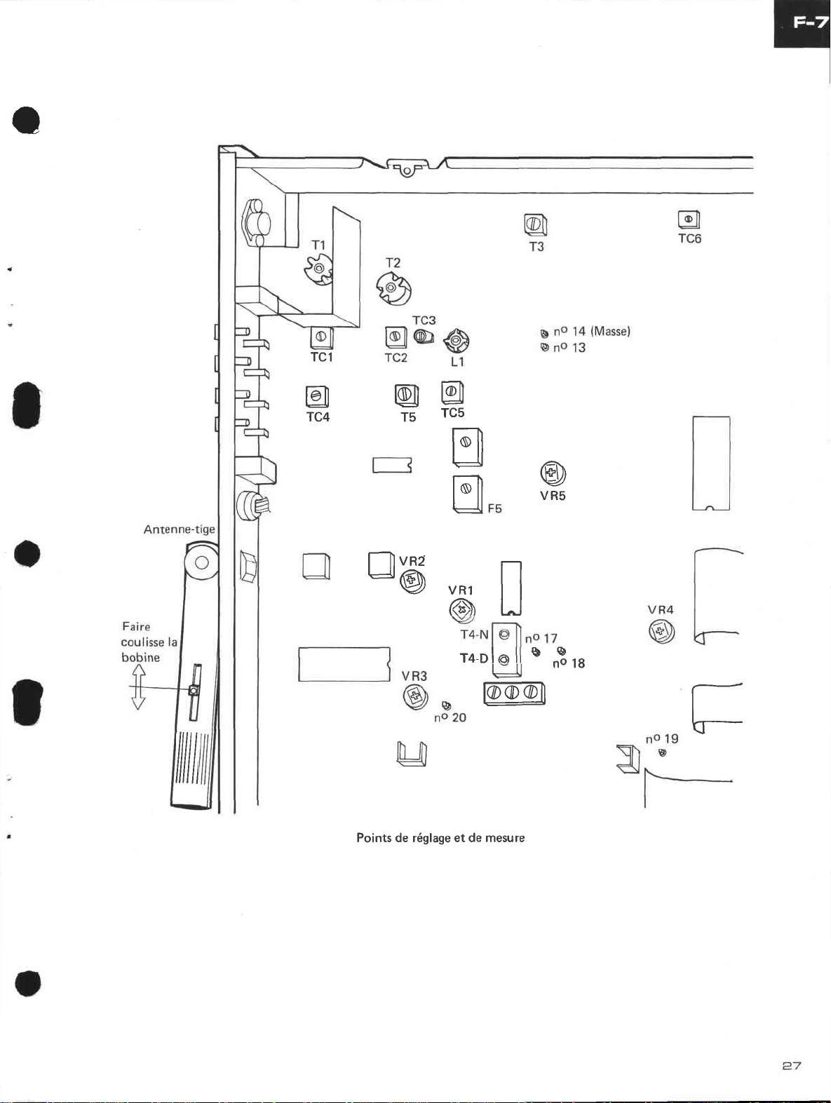
Points de réglage et de mesure
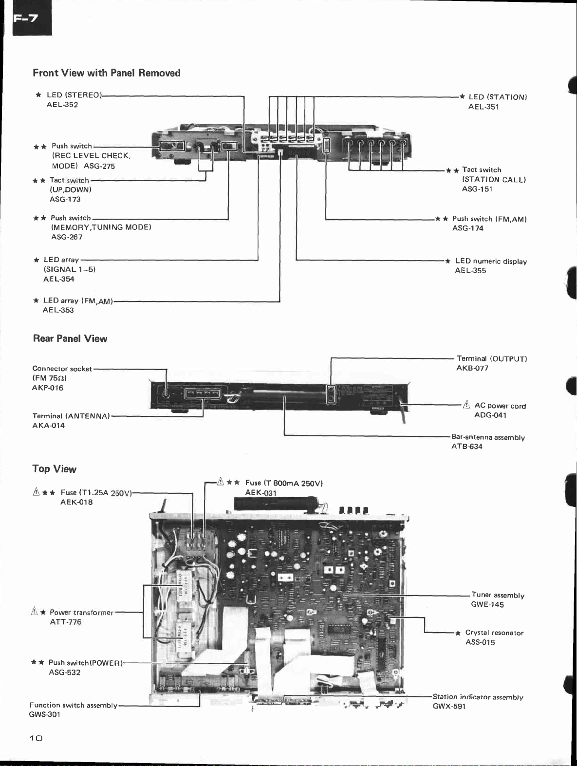
Front View with
(STEREO
*
LED
AE L.352
Push switch
* *
(REC
LEVEL
MODE) ASG-275
Tact
*
*
{UP,DOWN)
ASG-1
73
Panel
CHECK,
Removed
(STATION}
*
LED
AEL-351
Tact
switch
(STATION
ASG-151
CALL)
* Push switch
*
(MEMORY,TUNING
ASG-267
LED
array
*
(srGNAL
1-5)
AEL354
* LED
array
IFM
AEL.353
Rear
Panel View
Connector
(FM
socket
7so)
AKP.O16
View
**
(ANTENNAI
(T1.25A
Furr
AEK-O1
8
Terminal
AKA-o14
Top
A
MODE}
A**
Fuse
AEK
(T
800mA
250V)
tltr_
** Push
ASG.l
LED numeric
AEL.355
Terminal
AKB077
A
Bar-antenna
ATB€34
switch
74
(OUTPUT)
ps,,tæ,.
Ac
ADG041
(FM,AM)
display
s.r6
assembly
*
*
Push
switch(POWER
ASG-532
Function switch
GWS-301
10
assembly
,fd'Jr"
I
Station
GWX-591
Tuner
assembly
GWE-145
crystal resonalor
ASS-015
indicator
assembly
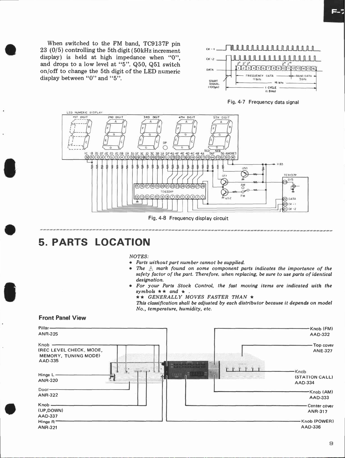
When
23
display) is
and drops
switched to the FM
(0
5)
controlling the 5th
|
held
low level
to a
on/off to change
display between
digit
at high
the 5th digit of
attd
"0"
impedance
at
"5". Q50, Q51
('5').
band, TC9137P
(
50kHz increment
'$rhen
switch
the
LED numeric
pin
"0",
."_,
nt
l||| t|l|
l|
n
Ll|
-t6
CYCLE
Smsl
l|
t|fll|fll|
ùts
I| 1|
PARTS
5.
Front Panel
Pillar
ANR.325
rsT
orctT
View
2NO OtGtT
3RD OIGIT 4TH
Fig.
LOCATION
NOlES:
o
Parts
c
o
without
The
tt
safety
factor
designation.
your
For
symbols
**
GENERALLY MOVES FASTER THAN
This classification
No., temperature,
OIG IT
4-8 Frequency
part
marh
found
of
the
Parts Stoch Control,
**
ond *
disptay
number cannot
on sotne
part.
Therefore, when
be adiusted by each distributor because
shall
humidity,
circuit
cornponent
etc.
Fig.4-7
be supplied.
replacing,
the
fast
Frequency
parts
indicates
mouing items are indicated
*
data
signal
the
be sure to use
importance of
it depends on
parts
identical
of
with
Knob
AAD.332
the
the
model
(FM)
(REC
LEVEL CHECK, MODE,
MEMORY,
AAD-335
Hinge L
ANR-320
ANR-322
Knob
{UP,DOWN}
AAD-337
Hinge
ANR.321
TUNING
R
MODE}
Top
ANE-327
(STATION
AAD-334
AAD.333
ANR-317
(POWERI
Knob
AAD.336
CALL)
ter
cover
(AM}
co\r€t
ASTAALS
MULlIVIBRÂlOR
lÈ
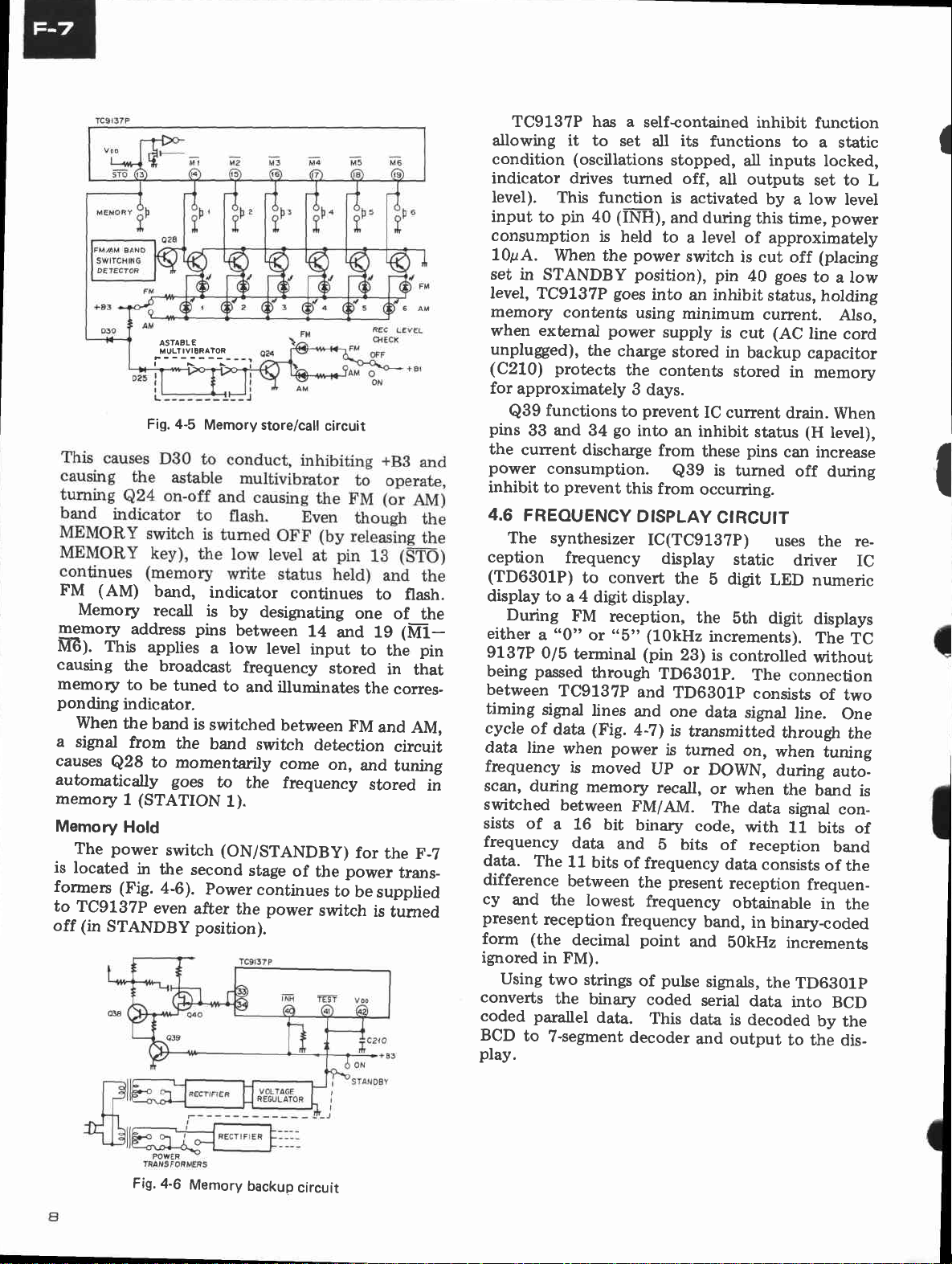
Fig. 4-5
FM (AM)
Memory
Smory
M6). This
causing
memory
ponding
lilhen
a
signal
causes
automatically
memory 1 (STATION
Memory
The
is
located
formers
to
TC9137P
off (in
band,
recall
address
applies
the broadcast
to
be
indicator.
the
band
from
to
Q28
Hold
power
in
(Fig.
even
STANDBY position).
Memory store/call
is
pins
tuned
is
the
momentarily
goes
switch (ON/STANDBy)
the
second
a-6).
Power
after
indicator
by designating
between
a low
to
switched
band
to
1).
the
continues
level
frequency
and
illuminates
between
switch
eome
the frequency
stage
of
continues
porver
circuit
one
14
and 1g
input
stored
FM
detection
on,
and
for
power
the
to
be
switch
to
of
to
the
in
the
corres-
and
circuit
tuning
stored
the
trans_
supplied
is
tumed
flash.
the
(NI-l-
pin
that
AM,
in
F-7
TC9137P ha.s a
allowing it to
condition
indicator drives
Ievel).
input
consumption
10pA.
set in
level,
memory
when exùemal power
unpluged),
(C210) protects
for
pins
the
power
inhibit
4.6
The synthesizer
ception
(TD6301P)
display
During
either
9137P
being
between
timing
cycle
data line
frequency
scan,
switched
sists of
frequency
data.
difference
cy
present
form (the
ignored
Using
converts
coded parallel
BCD
play.
This
pin
to
When the
STANDBY
TC9137P
contents
approximately
functions
Q39
and
33
cunent discharge
consumption.
prevent
to
FREOUENCY
frequency
to a 4
a
"0"
0/5
passed
TC9137P
signal
of
data
when
is
during
between
a 16
The
11
between
and
the
reception
in FM).
two strings
the
to
7-segment
set
(oscillations
tumed off,
function
(IÎi-H),
40
is held
goes
the
charge
to
go
34
to
convert
digit display.
FM
reception,
or
"5"
terminal (pin
through
lines
(Fig.
power
moved
memory
bit
data
and
bits
of
lowest
frequency
decimal
binary
data.
selfcontained
its
all
power
position),
into
using
the contents
3
days.
prevent
into
from
this
from
DISPLAY
IC(TC913?P)
(10kHz
TD6g01p.
and
and one
4-7)
Up or
recall,
FM/AM.
binary
5
frequency
the
frequency
point
pulse
of
coded
This
decoder
functions
stopped,
all outputs
is activated
and during
to
level
a
switch
pin
an inhibit
minimum
supply
stored
IC
an inhibit
these
is
Q39
occurring.
CIRCUIT
display
the
b
the
increments).
28) is
TDGBO1p
data
is
transmitted
is
turned
DOWN,
or
The data
code,
bits
present
band,
and
signals,
serial
data
and
inhibit
all inputs
by a low
this
of approximately
is
eut
40
status,
current.
is
cut
in
backup
stored
current
status
pins
turned
static
digit
bth
controlled
The
consists
signal
on,
when
with
of reception
data
consists
reception
obtainable
in
bOkHz
the
data
is
decoded
output
function
to
set to
time,
off
goes
to
(AC
line
capacitor
in
memory
drain.
(H
can increase
off
uses
driver
LED
numeric
digit
displays
The
without
connection
line.
through
when
during
the
band
signal con11
frequen_
binary-coded
incremenb
TD6B01p
into
by
to the
a
static
locked,
level
polver
(placing
a low
holding
Also,
cord
When
level),
during
the re-
IC
TC
of
two
One
the
tuning
auto_
is
bits of
band
of the
in
the
BCD
the
dis_
I
L
I
Fig.
4-6
Memory
backup
circuit
4.
CIRCUIT DESCRIPTIONS
MAJOR
4.1
F-7 is a
The
enced
as
to a
follows:
Frequency
1.
FM:
AM:
Tuning
2.
o
Tuning
once
key
band,
AM
UP or
quency
o
Positioning
AUTO
causes
mode.
scans
and
at,
mitting
strength.
o
Pressing
unit
unit.
the
Memory
3.
o
to
Up
into
o
A special
station
cut OFF.
tuning
Indicators
4.
.
Frequency
numeric
tuning
o
Signal
indicator.
o
FM
o
flashing
A
in
is
o
STATION
o
FM
FUNCTIONS
PLL digital
crystal
87.5MHz
522kHz
is by an
DO\ryN
bands to
and
the
the
tuning
a signal
to directly
6
memory.
the
tuned
is automatically
and
strength
and
"memory
STEREO
oscillator.
Range
to 1602kHz
changes
50kHz
the
pressing
unit to
this
In
frequency
into any
STATION
the
and
FM
memory
at
\ttlhen
displayed
is
display.
four
band
AM
band
write"
indicators
recePtion
synthesized tuner
Its main functions
108.0MH2
to
or
UP
key
be
exceeding
tune
digiLs
is
DOWN
frequency
in
TUNING
mode,
6 AM
the
indicator,
FM
the
depressed
scanned.
the UP
go
power is
indicated
indicator.
the
into
the
band,
broadcast
a
CALL
frequency
a
to
frequencies
holds
Five
the frequency
time
made
by
digits
for AM
indicates
(preset) status'
(memory address).
indicator.
refer-
in 50kHz
9kHz stePs.
in
key. Pressing
1 step
band). Holding
MODE
or
with
the
restored
by
(9kHz
causes the
DO\ilN
auto search
unit automatically
scan
station
prescribed
key
can
power
to
a ?-segment
used
are
tuning.
the LED
steps.
in
switch
key
tuning
stopping
trans-
level
causes
preset into
preset
be
of
supply
to the
station'
that
for
5-point
the unit
that
once
unit'
LED
are
the
the
the
fre'
to
of
the
the
FM
is
FM TUNER
4.2
Front-End
The FM
amplifier
diodes
The
or.
maintain
to
The local
thesizer
signal, and
the
to
comes
cv).
lF Amplifier
This section
element
(M5215L)
current-limiting
made
(consisting of an
detector,
Multiplex
This
contains
circuit,
automatic
killer
circuit,
The
does
or
noise
no
4.3
The
variable
2-ganged
The
thesizer
signal.
the
oscillator
the
To
the
in
addition
controlled
all
amplifier
front-end
(single
equivalent of a
the
local oscillator
stability
oscillator signal
circuit
the
variable
oscillator
the
and Detector
ceramic
is a single-stage
up of the
meter
and
Decoder
section
PLL
the
chopper
canceUer,
circuit,
and stereo
chopper
not establish
or distortion.
TUNER
AM
tuner
AM
capacitance
nin
tu
oscillator
local
circuit
resulting
The
variable
IC
capacitance
frequency
improve
built-in
a
has
to a
outPut
SECTION
uses a dual-gate MOS
stage),
and
resulting
capacitance
consists
limiter,
IF limiter
consists
system
type
muting
type
SECTION
g
caPacitor.
and
strong
by
level.
and
3-ganged tuning capacit-
uses an
during strong
compared with
tuning
frequency
of
two
filters.
and
system
IF
FM
amplifrer,
drive).
of
switching
MPX
stereo
amplifier,
reception
switching
a signal,
section
bar
an
uses IC
diodes
signal
compared
tuning
diodes
(tuning
signal
(automatic
AGC
antenna
in
FET
FET
variable
output buffer amp
is input into the
diodes where
(or
ICs and
The
differential
the
IC
decoder,
auto
circuit
thereby
the
is
input
with
voltage
frequency).
reception
response
capacitance
signal reception.
reference
the
applied
voltage
(PA40O6-A),
indicator
where
and
is
tuning
first
second
IC
signal
muting
equivalent
frequen-
two
stage
amplifier
stage
(PA3007-A)
quadrature
generator
pilot
selector,
control
circuit'
either
generating
(HA1138) and
the
into
reference
the
applied
is
it becomes
stability,
gain
control)
damping
the RF
to
RF
syn-
it be-
dual-
IC
is
and
signal
VCO
does
of a
syn-
to
coil,
 Loading...