

Pioneer DVR-650-H, DVR-650-HK Service manual
HDD/DVD
DivX
COPY HDMI
STANDBY/ON
DV IN
USB
DVR-650H-K
OPEN/CLOSE
S-VIDEO
VIDEO
L(MONO) R AUDIO
INPUT 2
ONE TOUCH
STOP REC
COPY
INPUT
REC MODE
CH
SELECT
REC
DVD RECORDER
DVR-650H-K
DVR-550H-K
DVR-450H-S
THIS MANUAL IS APPLICABLE TO THE FOLLOWING MODEL(S) AND TYPE(S).
Serial No.
Model Type Power Requirement Region No.
DVR-650H-K KCXV AC 120 V 1 &&DL######$$
DVR-550H-K KCXV AC 120 V 1 &&DL######$$
DVR-450H-S KCXV AC 120 V 1 &&DL######$$
Please confirm 3rd & 4th
alphabetical letters.
ORDER NO.
RRV3567
For details, refer to "Important Check Points for good servicing".
PIONEER CORPORATION 4-1, Meguro 1-chome, Meguro-ku, Tokyo 153-8654, Japan
PIONEER ELECTRONICS (USA) INC. P.O. Box 1760, Long Beach, CA 90801-1760, U.S.A.
PIONEER EUROPE NV Haven 1087, Keetberglaan 1, 9120 Melsele, Belgium
PIONEER ELECTRONICS ASIACENTRE PTE. LTD. 253 Alexandra Road, #04-01, Singapore 159936
PIONEER CORPORATION 2007
T-FZA-001 APR. 2007 printed in Japan

1234
SAFETY INFORMATION
A
This service manual is intended for qualified service technicians; it is not meant for the casual
do-it-yourselfer. Qualified technicians have the necessary test equipment and tools, and have been
trained to properly and safely repair complex products such as those covered by this manual.
Improperly performed repairs can adversely affect the safety and reliability of the product and may
void the warranty. If you are not qualified to perform the repair of this product properly and safely, you
should not risk trying to do so and refer the repair to a qualified service technician.
WARNING
This product contains lead in solder and certain electrical parts contain chemicals which are known to the state of Califor nia to
B
cause cancer, bir th defects or other reproductive harm.
Health & Safety Code Section 25249.6 – Proposition 65
NOTICE
(FOR CANADIAN MODEL ONLY)
Fuse symbols (fast operating fuse) and/or (slow operating fuse) on PCB indicate that replacement
parts must be of identical designation.
REMARQUE
(POUR MODÈLE CANADIEN SEULEMENT)
Les symboles de fusible (fusible de type
C
les pièces de remplacement doivent avoir la même désignation.
rapide) et/ou (fusible de type lent) sur CCI indiquent que
(FOR USA MODEL ONLY)
1. SAFETY PRECAUTIONS
The following check should be performed for the
continued protection o f the customer and ser vice
technician.
LEAKAGE CURRENT CHECK
Measure leakage current to a known ear th ground
(water pipe, conduit, etc.) by connecting a leakage
current tester such as Simpson Model 229-2 or
D
equivalent between the ear th ground and all exposed
metal par ts of the appliance (input/output terminals,
screwheads, metal overlays, control shaf t, etc.). Plug
the AC line cord of the appliance directly into a 120V
AC 60 H z outlet and tur n the AC power switch on. Any
current measured must not exceed 0.5 mA.
Leakage
current
E
Device
under
test
Also test with
plug reversed
(Using AC adapter
plug as required)
Te st all
exposed metal
surfaces
AC Leakage Test
tester
Reading should
not be above
0.5 mA
Earth
ground
ANY MEASUREMENTS NOT WITHIN THE
LIMITS OUTLINED ABOVE ARE INDICATIVE
OF A POTENTIAL SHOCK HAZARD AND
MUST BE CORRECTED BEFORE RETURNING THE APPLIANCE TO THE CUSTOMER.
2. PRODUCT SAFETY NOTICE
Many electrical and mechanical par ts in the appliance
have special safety related characteristics. These are
of ten not evident from visual inspection nor the
protection afforded by them necessarily can be obtained
by using replacement components rated for voltage,
wattage, etc. Replacement par ts which have these
special safety characteristics are
Service Manual.
Electrical components having such features are
identified by marking with a on the schematics and
on the parts list in this Service Manual.
The use of a substitute replacement component which
does not have the same safety characteristics as the
PIONEER recommended replacement one, shown in the
parts list in this Service Manual, may create shock, fire,
or other hazards.
Product Safety is
continuously under review and new
instructions are issued from time to time. For the latest
information, alw ay s consult the current P I O NEER
Service Manual. A subscription to, or additional copies
of, PIONEER Service Manual may be obtained at a
nominal charge from PIONEER.
identified in this
F
2
1 234
DVR-650H-K

5678
LABEL CHECK
WARNING!
The laser component is capable of emitting radiation exceeding
the limit for CLASS 1. A specially instructed person should do
servicing operation of the apparatus.
S
T
A
N
D
B
Y
/O
N
Laser Pickup specifications and
Laser characteristics
For CD
Wave length : 785 nm
Operating output :
Read mode : 1.07 mW (CW), Class1
Maximum output : Class1M
For DVD
Wave length : 660 nm
Operating output :
Read mode : 1.08 mW, Class1
Write mode : 21.89 mW (Pulse), Class1M
Maximum output : Class2M
VRW2262
A
B
C
REC
Additional Laser Caution
1. The ON/OFF(ON:low level,OFF:high level) status of the
CLAMP signals for detecting the loading state are detected
by the drive CPUs, and the design prevents laser diode
oscillation when the CLAMP signal turns OFF.
In normal operation, if no disc is clamped, the laser diode
oscillation is disabled.
However, the interlock does not always operate in the test
mode.
2. When the cover is opened, close viewing of the objective
lens with the naked eye will cause exposure to a Class 3A
laser beam.
D
E
DVR-650H-K
56
F
3
7
8
1234
[Important Check Points for Good Servicing]
In this manual, procedures that must be performed during repairs are marked with the below symbol.
Please be sure to confirm and follow these procedures.
A
1. Product safety
Please conform to product regulations (such as safety and radiation regulations), and maintain a safe servicing environment by
following the safety instructions described in this manual.
Use specified parts for repair.
Use genuine parts. Be sure to use important parts for safety.
Do not perform modifications without proper instructions.
Please follow the specified safety methods when modification(addition/change of parts) is required due to interferences such as
radio/TV interference and foreign noise.
B
C
D
Make sure the soldering of repaired locations is properly performed.
When you solder while repairing, please be sure that there are no cold solder and other debris.
Soldering should be finished with the proper quantity. (Refer to the example)
Make sure the screws are tightly fastened.
Please be sure that all scre
ws are fastened, and that there are no loose screws.
Make sure each connectors are correctly inserted.
Please be sure that all connectors are inserted, and that there are no imperfect insertion.
Make sure the wiring cables are set to their original state.
Please replace the wiring and cables to the original state after repairs.
In addition, be sure that there are no pinched wires, etc.
Make sure screws and soldering scraps do not remain inside the product.
Please check that neither solder debris nor screws remain inside the product.
There should be no semi-broken wires, scratches, melting, etc. on the coating of the power cord.
Damaged power cords may lead to fire accidents, so please be sure that there are no damages.
If you find a damaged power cord, please exchange it with a suitable one.
There should be no spark traces or similar marks on the power plug.
When spark traces or similar marks are found on the power supply plug, please check the connection and advise on secure
connections and suitable usage. Please exchange the power cord if necessary.
Safe environment should be secured during servicing.
When you perform repairs, please pay attention to static electricity, furniture, household articles, etc. in order to prevent injuries.
Please pay attention to your surroundings and repair safely.
2. Adjustments
To keep the original performance of the products, optimum adjustments and confirmation of characteristics within specification.
Adjustments should be performed in accordance with the procedures/instructions described in this manual.
3. Lubricants, Glues, and Replacement parts
Use grease and adhesives that are equal to the specified substance.
E
Make sure the proper amount is applied.
4. Cleaning
For parts that require cleaning, such as optical pickups, tape deck heads, lenses and mirrors used in projection monitors, proper
cleaning should be performed to restore their performances.
5. Shipping mode and Shipping screws
To protect products from damages or failures during transit, the shipping mode should be set or the shipping screws should be
installed before shipment. Please be sure to follow this method especially if it is specified in this manual.
F
4
1 234
DVR-650H-K

5678
CONTENTS
SAFETY INFORMATION .....................................................................................................................................2
1. SERVICE PRECAUTIONS................................................................................................................................7
1.1 NOTES ON SOLDERING...........................................................................................................................7
1.2 NOTES ON HANDLING THE HDD ............................................................................................................8
1.3 NOTES ON REPLACEMENT OF THE SDRAM.......................................................................................10
2. SPECIFICATIONS........................................................................................................................................... 11
2.1 ACCESSORIES........................................................................................................................................ 11
2.2 SPECIFICATIONS ....................................................................................................................................12
2.3 DISC/CONTENT FORMAT .......................................................................................................................14
2.4 PANEL FACILITIES ..................................................................................................................................18
3. BASIC ITEMS FOR SERVICE........................................................................................................................23
3.1 CHECK POINTS AFTER SERVICING.....................................................................................................23
3.2 QUICK REFERENCE ...............................................................................................................................24
3.3 PCB LOCATIONS.....................................................................................................................................25
3.4 JIGS LIST .................................................................................................................................................26
4. BLOCK DIAGRAM ..........................................................................................................................................28
4.1 OVERALL WIRING DIAGRAM.................................................................................................................28
4.2 OVERALL BLOCK DIAGRAM..................................................................................................................30
4.3 DETECTION AND ENCODE SYSTEM BLOCK DIAGRAM.....................................................................32
4.4 POWER BLOCK DIAGRAM .....................................................................................................................33
5. DIAGNOSIS ....................................................................................................................................................34
5.1 SETUP SEQUENCE.................................................................................................................................34
5.2 DIAGNOSIS OF THE MAIN ASSY...........................................................................................................35
6. SERVICE MODE.............................................................................................................................................39
6.1 VERSION INFORMATION, ETC. (FIRST SCREEN)................................................................................41
6.2 ATA/ATAPI DEBUG SCREEN (SECOND SCREEN)................................................................................46
6.3 VR-RECORDING-RELATED ERROR LOGS (FOURTH SCREEN).........................................................48
6.4 VR-PLAYBACK-RELATED ERROR LOGS (FIFTH SCREEN).................................................................52
6.5 DV SERVICE MODE ................................................................................................................................55
6.6 HDMI SERVICE MODE............................................................................................................................58
6.7 AGING MODE ..........................................................................................................................................60
6.8 USB CHECK MODE.................................................................................................................................62
6.9 HDD CHECK MODE.................................................................................................................................63
7. DISASSEMBLY...............................................................................................................................................69
8. EACH SETTING AND ADJUSTMENT............................................................................................................74
8.1 MODEL SETTING ....................................................................................................................................74
8.2 LD POWER ADJUSTMENT .....................................................................................................................75
8.3 CPRM ID NUMBER AND DATA SETTING...............................................................................................79
8.4 FIRMWARE UPDATE METHOD ..............................................................................................................83
8.5 VIDEO ADJUSTMENT FOR SPECIFIC AREA ........................................................................................86
9. EXPLODED VIEWS AND PARTS LIST ..........................................................................................................90
9.1 PACKING..................................................................................................................................................90
9.2 EXTERIOR SECTION ..............................................................................................................................92
9.3 FRONT PANEL SECTION ........................................................................................................................94
9.4 SERVICE LOADER MAIN SECTION.......................................................................................................96
10. SCHEMATIC DIAGRAM................................................................................................................................98
10.1 SERVICE TURB ASSY (1/3)..................................................................................................................98
10.2 SERVICE TURB ASSY (2/3)................................................................................................................100
10.3 SERVICE TURB ASSY (3/3)................................................................................................................102
10.4 SERVICE FLKY ASSY .........................................................................................................................104
10.5 SERVICE MAIN ASSY (1/5).................................................................................................................106
10.6 SERVICE MAIN ASSY (2/5).................................................................................................................108
10.7 SERVICE MAIN ASSY (3/5)................................................................................................................. 110
10.8 SERVICE MAIN ASSY (4/5)................................................................................................................. 112
10.9 SERVICE MAIN ASSY (5/5)................................................................................................................. 114
10.10 VDEC ASSY .......................................................................................................................................116
10.11 SERVICE DVUB ASSY.......................................................................................................................118
10.12 POWER SUPPLY ASSY.....................................................................................................................120
10.13 WAVE FORMS....................................................................................................................................122
11. PCB CONNECTION DIAGRAM ..................................................................................................................127
11.1 SERVICE TURB ASSY.........................................................................................................................128
11.2 SERVICE FLKY ASSY..........................................................................................................................132
11.3 SERVICE FRJB ASSY..........................................................................................................................134
11.4 SERVICE MAIN ASSY..........................................................................................................................136
11.5 VDEC ASSY .........................................................................................................................................140
DVR-650H-K
56
7
A
B
C
D
E
F
5
8

1234
11.6 SERVICE DVUB ASSY ........................................................................................................................ 144
11.7 POWER SUPPLY ASSY ...................................................................................................................... 146
12. PCB PARTS LIST....................................................................................................................................... 148
A
B
C
D
E
F
6
1 234
DVR-650H-K

5678
1. SERVICE PRECAUTIONS
When servicing this model, some service procedures may reset the customer settings
to the factory default settings. Make sure to explain this to the customer.
An HDD (Hard Disc Drive) is mounted in this product.
When an HDD becomes defective and inoperable, restoration of the user's data recorded on the HDD,
or copying of the user's recorded data to other media (such as a new HDD) is totally impossible.
Before servicing, OBTAI N THE USER'S PRIOR CONSENT to that effect.
The user must be made aware that all recorded data are deleted if the HDD is intialized.
1.1 NOTES ON SOLDERING
A
• For environmental protection, lead-free solder is used on the printed circuit boards mounted in this unit.
Be sure to use lead-free solder and a soldering iron that can meet specifications for use with lead-free solders for repairs
accompanied by reworking of soldering.
• Compared with conventional
Therefore, for lead-free soldering, the tip temperature of a soldering iron must be set to around 373 ºC in general, although
the temperature depends on the heat capacity of the PC board on which re
the soldering iron.
Compared with eutectic solders, lead-free solders have higher bond strengths but slower wetting times and higher melting
temperatures (hard to melt/easy to harden).
The following lead-free solders are available as service
• Par ts numbers of lead-free solder:
GYP1006 1.0 in dia.
GYP1007 0.6 in dia.
GYP1008 0.3 in dia.
eutectic solders, lead-free solders have higher melting points, by approximately 40 ºC.
working is required and the weight of the tip of
parts:
B
C
D
DVR-650H-K
56
E
F
7
7
8

1234
1.2 NOTES ON HANDLING THE HDD
(1) Cautions on Handling the HDD
• The HDD is very sensitive to shocks and vibrations. Care must be taken especially during operation (when the power is on).
• The HDD is very sensitive to electrostatic charges.
A
• Rapid change in temperature or humidity may cause deterioration of the HDD.
Note: After receiving damage caused
by any above-mentioned factors, the HDD may operate normally for dozens or some
hundreds of hours but then suddenly crash. If you are certain you have damaged a new repair part (HDD) while making
repairs, do not use the part.
The HDD is about 10 times as sensitive to shock
during operation than during nonoperation.
Reference: Main specifications on damage to the HDD
During operation During noperation
Shock G
(acceleration)
B
Temperature
change
Moisture change < 20%/hour
<approx. 20 G<approx. 200 G
< 20ºC/hour
Reference: Estimate value of falling distance vs. shock (G)
when the HDD is dropped without protection
Falling
distance
0.5 inch / 12.7 mm 387 217 200 26
1.0 inch / 25.4 mm 595 457 310 37
2.0 inch / 50.8 mm 1133 600 680 70
4.0 inch / 101.6 mm 1795 1040 1050 267
Landing
surface
Granite
surface
Concrete
floor
Synthetic-resin-
coated table
(2) Cautions on handling the product on which the HDD is mounted or the HDD as a repair part, and
examples of dangerous handling
[Cautions on handling the product on which the HDD is mounted]
• While the unit is turned on, the HDD is always in operation. Be sure NOT to impart shock to the unit.
Examples of dangerous handling: while the power is on
C
• Bumping on the bonnet
• Dropping an object, such as a small screwdriver or remote control unit, onto the bonnet, or bumping an
• Moving the unit by dragging
• Stacking another product on the unit
Note: Be sure NOT to impart shock, such as bumping or hitting a scre wdriver against the HDD, during diagnosis with the bonnet open.
object against the cabinet
Antistatic
sponge
Examples of dangerous handling: while the power is off
• Imparting strong shock, although the HDD is more resistant to shock when the power is off
• Dropping the unit from a height of several centimeters, or after lifting one side of the unit up, then letting the unit drop.
• Do NOT move the unit immediately
after the power is turned off. Wait at least 30 seconds after the indication on the FL
display changed from POWER OFF to the clock indication before moving the unit. If the AC power cord is accidentally
D
disconnected before turning the unit off,
wait at least for one minute before moving it. In this case, damage to the HDD
caused by sudden shutoff may be small, because the emergency relief mechanism is activated. However, if sudden shutoff
occurrs during recording or playback, recorded data may be damaged. Be sure to
check operations.
[Cautions on handling the HDD as a repair part]
1. Handle the HDD in a safe environment:
• Handle the HDD over an antistatic pad that can also absorb shock.
• Wear wrist bands to prevent electrostatic charges generated in your body from affecting the HDD.
2. The following must be observed when handling
the HDD:
• Handle one HDD at a time. Do NOT hold several HDDs at the same time.
• Grip the HDD on both sides so that you do not touch its terminals or circuit boards.
E
• Do NOT stack one HDD onto another HDD (even if the HDDs are protected
in antistatic bags).
• Do NOT bump the HDDs against one another.
• Do NOT bump any tool, such as a screwdriver, or other hard object against the HDD.
• When a repair part (HDD) is transported and there is a large temperature difference between outdoors
and indoors, to the
indoor, lea ve it in its package for about a half day to gradually cool or warm the HDD to room temperature before unpacking it.
[Notes on packing for shipment]
• When returning a defective HDD for analysis, handle with care as if it were a good product. Otherwise,
the results of analysis
may not be correct.
• When packing, use the antistatic bag and packing materials in which the repair part for service was delivered. Attach a copy
of the slip for service or a memo stating symptoms in as much detail as possible.
F
8
1 234
DVR-650H-K
5678
Outline and part No. of the HDDs
*Pioneer's part No. is not stamped.
SEAGATE
Model
Name
DVR-650H-K
DVR-550H-K
DVR-450H-S
Capacity
250GB
160GB
• When replacing the HDD, carefully check the capacity and manufacturer's part No. on the part label to avoid replacing with a similar but
inappropriate product. You can also check the model No. of the mounted HDD on the Service
• Do NOT use repair parts, such as commercially available HDDs, other than those designated above, as their functions, performance or
reliability cannot be guaranteed.
Pioneer's
Part No.
(for service)
VXF1131
VXF1137
Manufacture's
Part No.
ST3250820SCE
WD1600AABS-xxPRAx
mode screen.
Wistern Digital(160GB) Seagate(250GB)
Capacity
Manufacturer's
part No.
A
B
Date of
Manufacturer
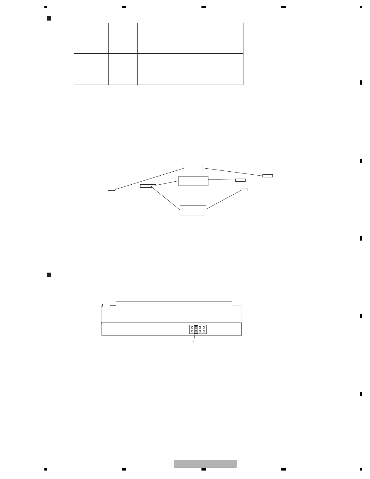
Confirmation of the jumper pin location of the HDD
VXF1137(DVR-550H-K, DVR-450H-S : 160GB)
7531
8
Jumper Pin
OPT1(Enabled)
C
D
642
E
DVR-650H-K
56
F
9
7
8

1234
1.3 NOTES ON REPLACEMENT OF THE SDRAM
Note when replacing the SDRAM
A
When replacement of the SDRAM (IC1201 or IC1221) on the MAIN Assy is required, identify the manufacturer of the SDRAM.
If the SDRAM that needs replacement was manufactured by ELPIDA, both IC1201 and IC1221 must be replaced at the same
time.
SDRAMs for
How to identify the manufacturer
Confirm the name of the manufacturer stamped on the surface of the part.
B
service are manufactured by SAMSUNG.
By ELPIDA (replacement of both SDRAMs required) By SAMSUNG (replacement of only the defective SDRAM possible)
C
Measures to be taken
1 If the SDRAM that needs replacement was manufactured by ELPIDA:
Replace both IC1201 and IC1221 at the same time.
2 If the SDRAM that needs replacement was manufactured by SAMSUNG:
Replacement of only the defective SDRAM (IC1201 or IC1221) is possible.
Possible malfunctions
If SDRAMs made by different manufacturers are mounted on the MAIN Assy, the following malfunctions may occur:
1 The power does not come on.
D
2 High-speed dubbing disabled
3 Other malfunctions related to the SDRAM
E
F
10
1 234
DVR-650H-K
5678
2. SPECIFICATIONS
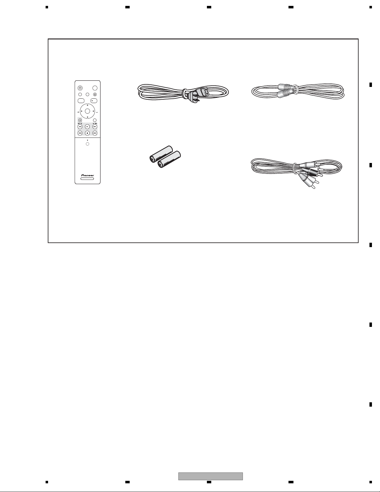
2.1 ACCESSORIES
For DVR-650H-K/KCXV
• Remote control ×1
(VXX3223)
STANDBY/ON
HDD/DVD
HOME MENU STOP RECHELP
TOP MENU
DISC
REC
NAVIGATOR
CHANNEL
+
ENTER
PAUSE RETURN
CHANNEL
–
PLAY
PREV NEXT
STOP
OPEN
CM
SKIP
//
CM
BACK
• Operating Instructions (English)(VRB1462)
• Operating Instructions (French)(VRC1382)
• Quick Start Guide (English)(VRG1021)
• Quick Start Guide (French)(VRG1022)
• Warranty Card
• Power cable ×1
(ADG7021 )
• Dry cell batteries ×2
(AA/R6P)
A
• RF antenna cable ×1
(VDE1088)
B
• Audio / Video cable ×1
(red/white/yellow)
(VDE1077)
C
D
E
F
DVR-650H-K
56
11
7
8

1234
2.2 SPECIFICATIONS
General
Power requirements .................................... 120 V, 60 Hz
A
B
C
Power consumption
DVR-650H-K......................................................... 48 W
DVR-550H-K......................................................... 46 W
DVR-450H-S......................................................... 42 W
Power consumption in standby mode................... 0.33 W
Weight
DVR-650H-K................................... 4.1 kg (9 lbs. 1 oz.)
DVR-550H-K................................... 4.1 kg (9 lbs. 1 oz.)
DVR-450H-S................................... 4.1 kg (9 lbs. 1 oz.)
Dimensions
......................... 420 mm
Operating temperature ............................+5 °C to +35 °C
Operating humidity
........................................5 % to 85 % (no condensation)
TV system............................................................... NTSC
Readable discs
DVD-Video, DVD-RW, DVD-R, DVD+R, DVD+RW,
DVD-RAM, Video CD, Super VCD, CD, CD-R/-RW
(WMA, MP3, JPEG, CD-DA, DivX)
Recording discs and formats
DVD-R/-RW: VR
DVD+R/+RW: +VR mode
DVD-RAM: VR mode
DVD-R DL: VR mode and Video mode
DVD+R DL: +VR mode
Video recording format
Sampling frequency.......................................... 13.5 MHz
Compression format .............................................. MPEG
Audio recording format
Sampling frequency...............................................48 kHz
Compression format ............ Dolby Digital or Linear PCM
9
/16 in. (W) x 3 in. (H) 11 6/16 in. (D))
(16
mode and Video mode
(Front panel display: off)
(W) x 75 mm (H) x 288 mm (D)
(+41 °F to +95 °F)
(uncompressed)
Recording time
HDD
DVR-650H-K (250 GB)
.............................................................. Approx. 36 h
XP+
Fine (XP) ..................................................... Approx. 53 h
Standard Play (SP).................................... Approx. 106 h
Long Play (LP)........................................... Approx. 212 h
Extended Play (EP) ................................... Approx. 319 h
Super Long Play (SLP).............................. Approx. 425 h
Super Extended Play (SEP) ...................... Approx. 532 h
Manual Mode (MN)........................ Approx. 36 h to 711 h
DVR-550H-K/DVR-450
XP+.............................................................. Approx. 23 h
Fine (XP) ..................................................... Approx. 34 h
Standard Play (SP)...................................... Approx. 68 h
Long Play (LP)........................................... Approx. 136 h
Extended Play (EP) ................................... Approx. 204 h
Super Long Play (SLP).............................. Approx. 272 h
Super Extended Play (SEP) ...................... Approx. 340 h
Manual Mode (MN)........................ Approx. 23 h to
DVD-R/-RW, DVD+R/+RW, DVD-RAM
Fine (XP) ....................................................... Approx. 1 h
Standard Play (SP)........................................ Approx. 2 h
Long Play (LP)............................................... Approx. 4 h
Extended Play (EP) ....................................... Approx. 6 h
Super Long Play (SLP).................................. Approx. 8 h
Super Extended Play (SEP) ........................ Approx. 10 h
Manual Mode (MN)
DVD-R/-RW/-RAM.......................... Approx. 1 h to 13 h
DVD+R/+RW .................................... Approx. 1 h to 8 h
DVD-R DL/DVD+R DL
Fine (XP) .............................................. Approx. 1 h 51 m
Standard Play (SP)............................... Approx. 3 h 35 m
Long Play (LP)...................................... Approx. 7 h 11 m
Extended Play (EP
Super Long Play (SLP)....................... Approx. 14 h 21 m
Super Extended Play (SEP) ............... Approx. 17 h 57 m
Manual Mode (MN)
DVD-R DL.............................. Approx. 1 h 51 m to 24 h
DVD+R DL.................... Approx. 1 h 51 m to 14 h 21 m
H-S (160 GB)
455 h
(DVD-R/-RW, DVD-RAM
) ............................ Approx. 10 h 46 m
(DVD-R DL only)
only)
Timer
Programmes..............................1 month/32 programmes
Clock...............................................................Quartz lock
D
E
(12-hour digital display)
F
12
1 234
DVR-650H-K

5678
Tuner
Receivable channels
VHF ............................................................. 2 ch to 13 ch
UHF ........................................................... 14 ch to 69 ch
CATV.................................................... C1 ch to C125 ch
Input/Output
VHF/UHF antenna input/output terminal
...........................................................VHF/UHF set 75 Ω
Video Input ............................... Input 1, 3 (rear), 2 (front)
Input level ................................................... 1 Vp-p (75 Ω)
Jacks .................................................................RCA jack
Video Output................................................... Output 1, 2
Output level ................................................ 1 Vp-p (75 Ω)
Jacks .................................................................RCA jack
S-Video Input........................... Input 1, 3 (rear), 2 (front)
Y (luminance) -
C (colour) - Input level ......................... 265 mVp-p (75 Ω)
Jacks ......................................................... 4 pin mini DIN
S-Video Output............................................... Output 1, 2
Y (luminance) - Output level....................... 1 Vp-p (75 Ω)
C (colour) - Output level ...................... 265 mVp-p (75 Ω)
Jacks ......................................................... 4 pin mini DIN
Component video output
Output level .........................................Y: 1.0 Vp-p (75 Ω)
Jacks ............................................................... RCA
Audio Input .........................Input 1, 3 (rear), 2 (front) L/R
During audio input ............................................... 2 V rms
Jacks ............................................................... RCA jacks
Audio Output............................................ Output 1, 2 L/R
During audio output ............................................. 2 V rms
Jacks ............................................................... RCA jacks
Control input ....................................................... Mini jack
Digital audio output............................................... Coaxial
DV input (DVR-650H-K and
...................................................................... 4 pin (front)
USB (DVR-650H-K and DVR-550H-K only)
...........................................Type A (front), Type B (front)
HDMI ......................................................................19 pin
Input level.......................... 1 Vp-p (75 Ω)
(Input impedance: more than 22 kΩ)
(Output impedance: less than 1.5 kΩ)
(F-shape connector)
, PR: 648 mVp-p (75 Ω)
P
B
DVR-550H-K only)
(i.LINK/IEEE 1394 standard)
jacks
Supplied accessories
Remote control ............................................................... 1
Dry cell batteries (AA/R6P).............................................2
Audio / Video cable (red/white/yellow)............................1
RF antenna cable ........................................................... 1
Power cable.................................................................... 1
Operating Instructions
Note: The specifications and design of this product are
subject to change without notice, due to improvement.
This product includes FontAvenue® fonts licenced
by NEC Corporation. FontAvenue is a registered
trademark of NEC Corporation.
Microsoft product screen shots reprinted with
permission from Microsoft
Corporation.
A
B
C
D
E
F
DVR-650H-K
56
13
7
8
1234
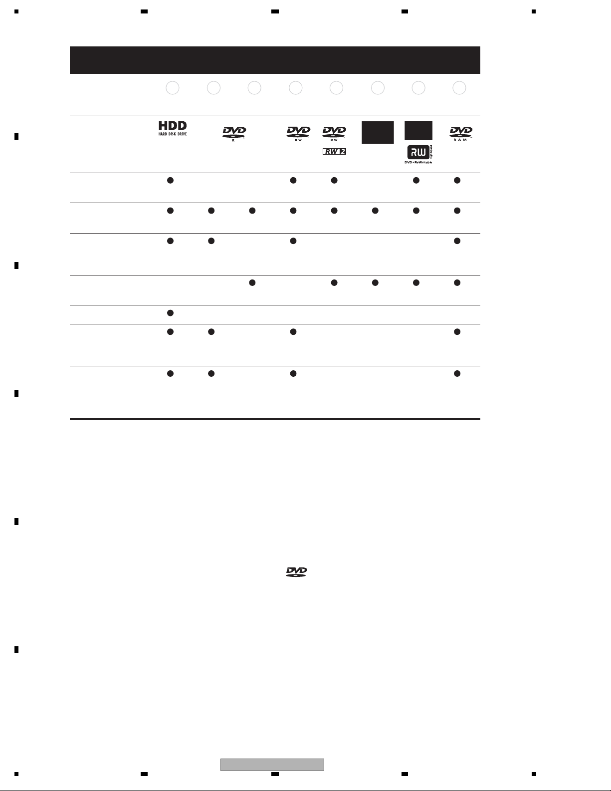
2.3 DISC/CONTENT FORMAT
HDD DVD-R DVD-RW DVD+R
A
Marks used in this
manual
HDD
DVD (VR) DVD (Video) DVD (VR) DVD (Video)
DVD+R DVD+RW DVD-RAM
DVD
+RW
DVD-
RAM
*13, 16*2*1*1
Logos
Re-recordable/
B
Erasable
Editing of recorded
*3 *3 *3 *14
*4 *4 *4 *4
programmes
Recording of Copy-
*12 *12 *12
once protected
material
Playback in other
players/recorders
n/a *5 *6 *7 *6
*6, 15
*8 *9
Chase play
C
16:9 and 4:3
programme
recording
Dual mono
broadcast
*10, 11
*11 *11 *11
recording of both
audio channels
Notes to table
D
E
*1 Must be initialized for VR mode recording.
*2 Must be initialized for Video mode recording
*3 Erasable, but free space does not increase.
*4 Cannot erase sections, edit chapters or use playlist
editing.
*5 Must be compatible with DVD-R (VR) playback.
*6 Finalize using this recorder
some units).
*7 Must be compatible with DVD-RW (VR) playback.
*8 Must be compatible with DVD+RW playback.
*9 Must be compatible with DVD-RAM playback.
*10 Only when HDD Recording Format is set to Video
Mode Off.
(may not playback in
*11 Only when the recording mode is not
*12 CPRM-compatible discs only.
*13 Take the disc out of the cartridge before use. Only
Panasonic and Maxell discs have been tested to work
reliably with this recorder. Discs f rom other makers may
become unusable when recorded or edited.
*14 Erasing a title does not increase the
recording time, nor increase the number of recordable
titles left.
*15 Must be compatible with DVD+R playback.
*16 Depending on the disc, it may have to be initialized
before it can be recorded. In this case, initialization
will take about an hour.
is a trademark of DVD Format/Logo
Licensing Corporation.
set to LPCM.
available
F
14
1 234
DVR-650H-K
5678
Using DVD-R DL/DVD+R DL discs
DVD-R DL (Dual-Layer) and DVD+R DL
(Double-Layer) discs contain two recordable
layers on a single side, giving about 1.8
times the recording capacity of a
conventional single-layer disc. This unit can
record to both DVD-R DL and DVD+R DL
discs.
• If you intend to play DVD-R DL (Video
mode) or
DVD+R DL discs recorded on
this unit on other DVD recorders/players,
you must finalize them. (Note that some
DVD recorders/players may not play
even finalized DL discs.)
• This logo indicates that the disc is a
DVD-R DL or DVD+R DL disc:
Correct operation has been confirmed
for
DL discs:
• DVD-R DL ver. 3.0/2x to 4x
Mitsubishi Kagaku Media (Verbatim)
• DVD-R DL ver. 3.0/2x to 8x
Mitsubishi Kagaku Media (Verbatim)
That’s
JVC
• DVD+R DL 2.4x
Mitsubishi Kagaku Media (Verbatim)
RICOH
• DVD+R DL 2.4x to 8x
Mitsubishi Kagaku Media (Verbatim)
RICOH
About DualDisc playback
A DualDisc is a new two -sided disc, one side
of which contains DVD content –video,
audio, etc. –while the other side contains
non-DVD content such as digital audio
material.
The non-DVD, audio side of the disc is not
compliant with the CD Audio specification
and therefore
It is possible that when loading or ejecting a
DualDisc, the opposite side to that being
played will be scratched. Scratched discs
may not be playable.
may not play.
The DVD side of a DualDisc plays in this
product. DVD-Audio content will not play.
For more detailed information on the
DualDisc specification, please refer to the
disc manufacturer or disc retailer.
Other disc compatibility
In addition to DVD, this recorder is
compatible with a wide range of disc types
(media) and formats. Playable discs will
generally feature one of the logos on the disc
and/or disc packaging shown below. Note
however that some disc types, such as
recordable CD (and
DVD), may be in an
unplayable format — see below for further
compatibility information.
Audio CD CD-RCD-RW
Video CD
CD-R/-RW compatibility
This recorder cannot record CD-R or CD-RW
discs.
• Readable formats: CD-Audio, Video CD,
ISO 9660 CD-ROM* containing MP3,
WMA, JPEG or DivX files
*ISO 9660 Level 1 or 2 compliant. CD
physical format: Mode1, Mode2 XA F orm1.
Romeo and Joliet file systems are both
compatible
with this recorder.
• Multi-session playback: Yes (except CD-
Audio and Video CD)
• Unfinalized disc playback: CD-Audio
only
Compressed audio compatibility
• Compatible media: DVD-ROM,
DVD-R/-RW, DVD+R/+RW, DVD-RAM,
CD-ROM, CD-R, CD-RW
DVR-650H-K/DVR-550H-K only: USB
• Compatible formats: MPEG-1 Audio
Layer 3 (MP3), Windows Media Audio
(WMA)
• Sampling rates: 32 kHz, 44.1 kHz or
48 kHz
• Bit-rates: Any (128 kbps
recommended)
or higher
A
B
C
D
DVR-650H-K
56
E
F
15
7
8

1234
• Variable bit-rate (VBR) MP3 playback:
DivX video compatibility
Yes
• VBR WMA playback: No
A
B
• WMA encoder compatibility: Windows
Media Codec 8 (files encoded using
Windows Media Codec 9 may be playable
but some parts of the specification are not
supported; specifically, Pro, Lossless,
Voice and VBR)
• DRM (Digital
Rights Management)1 file
playback: No
• File extensions: .mp3, .wma (these must
be used for the recorder to recognize
MP3 and WMA files – do not use for
other file types)
• File structure: Up to 99 folders/999 files
(if these limits are exceeded, only files
and folders up to these
limits are
playable)
DivX is a compressed digital video format
®
created by the DivX
video codec from DivX,
Inc. This recorder can play DivX video files
burned on CD-R/-RW/-ROM discs. Keeping
the same terminology as DVD-Video,
individual DivX video files are called “Titles”.
When naming files/titles on a CD-R/-RW disc
prior to burning, keep in
mind that by default
they will be played in alphabetical order.
• Official DivX
• Plays all versions of DivX
(including DivX
playback of DivX
®
Certified product.
®
®
6) with standard
®
media files.
video
• File extensions: .avi and .divx (these
must be used for the recorder to
WMA (Windows Media™ Audio)
compatibility
This recorder can playback Windows Media
Audio content.
WMA is an acronym for Windows Media
Audio and refers to an audio compression
technology developed by Microsoft
C
Corporation. WMA content can be encoded
by using Windows Media Player for
Windows XP, Windows Media Player
9 or
recognize DivX video files). Note that all
files with the .avi extension are recognized
as MPEG4, but not all of these are
necessarily DivX video files and therefore
may not
be playable on this recorder.
• File structure: Up to 99 folders or 999
files.
DivX, DivX Certified, and associated logos are
trademarks of DivX, Inc. and are used under
license.
Windows Media Player 10 series.
Windows Media is a trademark of Microsoft
Corporation.
This product includes technology owned by
Microsoft Corporation and cannot be used or
distributed without a license from Microsoft
Licensing, Inc.
D
Note
1 DRM (digital rights management) copy protection is a technology designed to prevent unauthorized copying by restricting
playback, etc. of compressed audio files on devices other than the PC (or other recording equipment) used to record it.
For detailed information, please see the instruction manuals or help f
E
F
iles that came with your PC and/or software.
16
DVR-650H-K
1 234
5678
DivX® VOD contentDivX® VOD content
DivX
In order to play DivX VOD (video on demand)
content on this recorder, you first need to
register the recorder with your DivX VOD
content provider. You do this by generating a
DivX VOD registration code, which you
submit to your provider.
Some DivX VOD content may only be
playable
load a disc containing this type of DivX VOD
content, the remaining number of plays is
shown on-screen and you then have the
option of playing the disc (thereby using up
one of the remaining plays), or stopping. If
you load a disc
VOD content (for example, content that has
zero remaining plays), the message Rental
Expired is displayed.
If your DivX VOD content allows an unlimited
number of plays, then you may load the disc
into your recorder and play the content as
often as
displayed.
a fixed number of times. When you
that contains expired DivX
you like, and no message will be
Important
• DivX VOD content is protected by a DRM
system. This restricts playback of
content to specific, registered devices.
• If you load a disc that contains DivX VOD
content not authorized for this recorder,
the message Authorization Error is
displayed
and the content will not play.
• Resetting the recorder will not cause
you to lose your registration code.
• File extensions: .jpg, .jpeg, .jpe, .jif, .jfif
(must be used for the recorder to
recognize JPEG files – do not use for
other file types)
• File structure: The recorder can load up
to 99 folders/999 files at one time (if there
are
more files/folders that this on the disc
then more can be reloaded)
PC-created disc compatibility
Discs recorded using a personal computer
may not be playable in this unit due to the
setting of the application software used to
create the disc. In these particular
instances, check with the software publisher
for more detailed information.
Discs recorded in packet write mode
(UDF
format) are not compatible with this
recorder.
Check the DVD-R/-RW or CD-R/-RW
software disc boxes for additional
compatibility information.
Dolby Digital
Manufactured under license from Dolby
Laboratories. “Dolby” and the double-D
symbol are trademarks of Dolby Laboratories.
DTS
A
B
C
JPEG file compatibility
• Compatible formats: Baseline JPEG and
EXIF 2.2* still image files
*File format used by digital still cameras
• Sampling ratio: 4:4:4, 4:2:2, 4:2:0
• Horizontal resolution: 160 to 5120 pixels
• Vertical resolution: 120 to 3840 pixels
• Progressive JPEG compatible: No
D
“DTS” and “DTS Digital Out” are registered
trademarks of DTS, Inc.
E
F
DVR-650H-K
56
17
7
8

1234
2.4 PANEL FACILITIES
Rear Panel
A
B
C
1 2
ANTENNA
IN
R
OUT
INPUT 1/AUTO START REC
INPUT 3
L
6 7 8 9 10
R
S-VIDEO
VIDEOAUDIO
Y
COMPONENT VIDEO OUT
3 4 5
VIDEOAUDIO
L
OUTPUT 2
S-VIDEO
CONTROL
IN
B
P
P
R
OUTPUT 1
1 ANTENNA IN (RF IN)/OUT
Connect your TV antenna to the ANTENNA
IN (RF IN) jack. The signal is passed through
to the ANTENNA OUT jack for connection to
your TV.
2 INPUT 3
Stereo analog audio, video and S-video
inputs for connection to a satellite receiver,
set top box, etc.
3 OUTPUT 2
Stereo analog audio, video and S-video
outputs for connection to a TV or AV
amplifier/receiver.
4 HDMI OUT
HDMI output for high quality digital audio
and video.
5 DIGITAL AUDIO OUT (COAXIAL)
Coaxial digital audio jack for connecting to
an AV amplifier/receiver, Dolby Digital
/DTS
decoder or other equipment with a digital
DIGITAL
HDMI OUT
AUDIO OUT
COAXIAL
AC IN
7 COMPONENT VIDEO OUT
A high-quality video output for connecting to
a TV or monitor with a component video
input.
8 OUTPUT 1
Stereo analog audio, video and S-video
outputs for connection to a TV or AV
amplifier/receiver.
9 CONTROL IN
Use to control this recorder from the remote
sensor of another Pioneer component with a
CONTROL OUT terminal and bearing the
Pioneer
mark. Connect the CONTROL
OUT of the other component to the
CONTROL IN of this recorder using a mini-
plug cord.
10AC IN – Power inlet
Connect to a power outlet using the supplied
power cable after making all other
connections.
input.
6 INPUT 1/AUTO START REC
Stereo analog audio, video and S-video
inputs for connection to a satellite receiver,
set top box, etc.
D
E
F
18
DVR-650H-K
1 234
5678
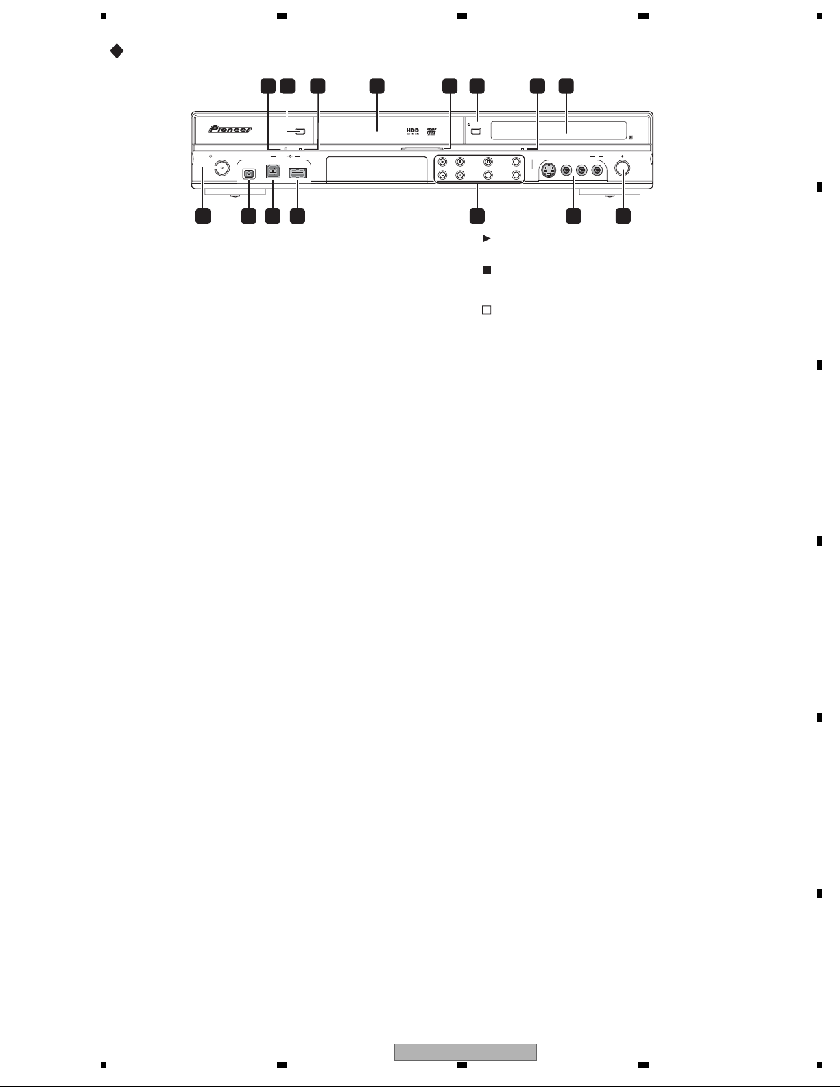
Front panel
HDD/DVD
DivX
COPY HDMI
STANDBY/ON
DV IN
USB
1 DivX indicator
Lights when this recorder plays DivX video
files.
2 HDD/DVD
Press to switch between HDD and DVD for
recording and playback.
3 COPY indicator
Lights when copying is underway.
4 Disc tray
5 HDD/DVD indicator
Indicator lights blue when the hard disk
(HDD) is selected; orange when the DVD
drive is
selected.
6
OPEN/CLOSE
Press to open/close the disc tray.
7 HDMI indicator
Lights when this recorder is connected to
HDMI (HDCP) compatible component.
8 Front panel display and IR remote
sensor
9
STANDBY/ON
Press to switch the recorder on/into standby.
10DV IN
A DV input i.LINK connector, suitable for
connecting a DV camcorder.
11 USB port (Type B)
USB port for connecting a PictBridgecompatible printer or PC.
12USB port (Type A)
USB port for connecting a digital camera,
keyboard or other USB device.
84 61 732 5
DVR-650H-K/DVR-550H-K
OPEN/CLOSE
S-VIDEO
VIDEO
INPUT 2
ONE TOUCH
STOP REC
COPY
INPUT
SELECT
REC MODE
CH
L(MONO) R AUDIO
REC
15149 11 1210 13
13
Press to start or restart playback.
Press to stop playback.
STOP REC
Press to stop recording.
ONE TOUCH COPY
Press to start One Touch Copy of the
currently playing title to DVD or the
HDD.
CH +/–
Use to change channels, skip chapters/
tracks, etc.
INPUT SELECT
Press to change the input used for
recording.
REC MODE
Press repeatedly to cycle through
recording modes (picture quality).
14 INPUT 2
Audio/video input (stereo analog audio;
composite and S-video), especially suitable
for camcorders, game consoles, portable
audio, etc.
15
REC
Press to start recording. Press repeatedly to
set the recording time in 30 minute blocks.
A
B
C
D
DVR-650H-K
56
E
F
19
7
8

Display
A
1234
2 43 5 61
PM
L
P
R
10
1
Lights during playback; blinks when
playback is paused.
2
Lights when copying.
3
B
Lights during recording; blinks when
recording is paused.
4 PM
Lights to indicate PM (after midday) for the
clock display.
5
Lights when a timer recording has been
set. (Indicator blinks if the timer has
been set to DVD but there isn’t a
recordable disc loaded, or the timer has
been set
C
recordable.)
SAP
Lights when the currently selected TV
channel has a Second Audio
Programme channel.
9 78
to HDD but the HDD is not
6 Recording quality indicators
XP
Lights when the recording mode is set to
XP (best quality).
SP
Lights when the recording mode is set to
SP (standard play).
LP/SLP
Lights when the recording mode is set to
LP (long play) or SLP (super-long play).
EP/SEP
Lights when the recording mode is
set to
EP (extended play) or SEP (super-
extended play).
MN
Lights when the recording mode is set to
MN (manual recording level) mode.
7 CH
Channel indicator for the built-in TV tuner.
8 Character display
9 R/RW
Lights when a recordable DVD-R or DVD-RW
Indicates which channels are recorded
when Dual Mono is selected.
Lights when the component video output
is set to progressive scan.
D
disc is loaded.
10PL
Lights when a
VR mode disc is loaded
and the recorder is in Play List mode.
2 3
Shows the remote control mode (if nothing
is displayed, the remote control mode is 1).
V
Lights when an unfinalized Video mode
disc is loaded.
E
F
20
1 234
DVR-650H-K
5678
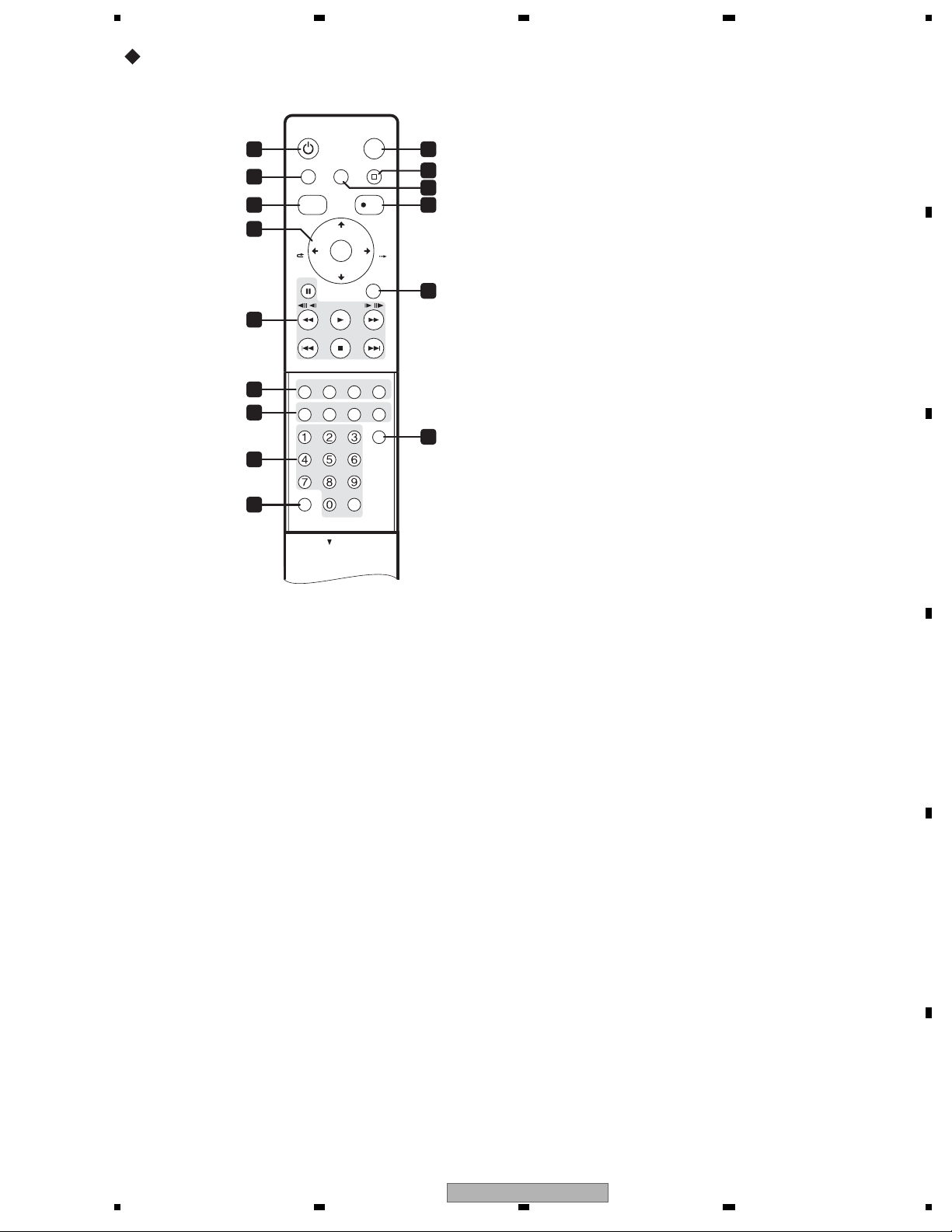
Remote Control Unit
STANDBY/ON
1 10
2
3 13
4
5
6
7
8
9
1 STANDBY/ON
Press to switch the recorder on/into standby.
2 HELP
Press for help on how to use the current GUI
screen.
3 DISC NAVIGATOR / TOP MENU
Press to display the Disc Navigator screen,
or the top menu if a DVD-Video or finalized
DVD-R/-RW (Video) disc
TOP MENU
DISC
NAVIGATOR
CM
BACK
PAUSE RETURN
PREV NEXT
AUDIO SUBTITLE ANGLE
DISPLAYMENU
GHI JKL MNO
PQRS TUV WXYZ
+
VCR Plus+ CLEAR
HOME MENU STOP RECHELP
CHANNEL
+
ENTER
CHANNEL
–
PLAY
STOP
REC MODE
ABCDEF
OPEN
HDD/DVD
REC
//
PLAY MODE
ONE TOUCH COPY
INPUT SELECT
CLEAR
OPEN
is loaded.
and ENTER
4
Used to navigate all on-screen displays.
Press ENTER to select the currently
highlighted option.
A
CM BACK (commercial back)
11
12
Press repeatedly to skip progressively
backward through the video playing.
CM SKIP (commercial skip)
Press repeatedly to skip progressively
CM
SKIP
14
forward through the video playing.
CHANNEL +/–
Press to change the channel
in TV tuner.
5 Playback controls
of the built-
B
PAUSE
Press to pause playback or recording.
PLAY
Press to start playback.
STOP
15
Press to stop playback.
Press to skip to the previous or next title/
chapter/track/folder; or to display the
previous or next menu page.
C
Press to start reverse or forward
scanning. Press again to change the
speed.
While paused, press and hold to start
slow-motion playback. Press
repeatedly
to change the playback speed.
While paused, press to advance a single
frame in either direction.
D
DVR-650H-K
56
E
F
21
7
8

1234
6 playback function buttons
AUDIO
Press to change the audio language or
A
channel. (When the recorder is stopped,
press to change the tuner audio.)
SUBTITLE
Press to display/change the subtitles
included in multilingual DVD-Video
discs.
ANGLE
Press to switch camera angles on discs
with multi-angle scenes.
PLAY MODE
Press to
B
repeat, programme play, etc.).
change the play mode (search,
STOP REC
11
Press to stop recording.
12 HOME MENU
Press to display the Home Menu, f rom which
you can navigate all the functions of the
recorder.
13
REC
Press to start recording. Press repeatedly to
set the recording time in blocks of 30 mins.
14 RETURN
Press to go back one level in the on-screen
menu or display.
15 INPUT SELECT
Press to change the input to use for
recording.
7 DISPLAY
Displays/changes the on-screen
information displays.
MENU
Press to display the disc menu if a DVDVideo, finalized DVD-R/-RW or finalized
DVD+R/+RW disc is loaded.
REC MODE
Press repeatedly to change the
recording
C
ONE TOUCH COPY
mode (picture quality).
Press to start One Touch Copy of the
currently playing title to DVD or the HDD.
8 Number buttons, CLEAR
Use the number buttons for track/
chapter/title selection; channel
selection, and so on. The same buttons
can also be used to enter names for
titles,
discs and so on.
Use CLEAR to clear an entry and start
again.
D
9 VCR Plus+
®
Press then use the number buttons to enter
®
a PlusCode
programming number for
timer recording.
10 HDD/DVD
Press to select the hard disk (HDD) or DVD
for recording and playback.
E
F
22
1 234
DVR-650H-K
5678
3. BASIC ITEMS FOR SERVICE
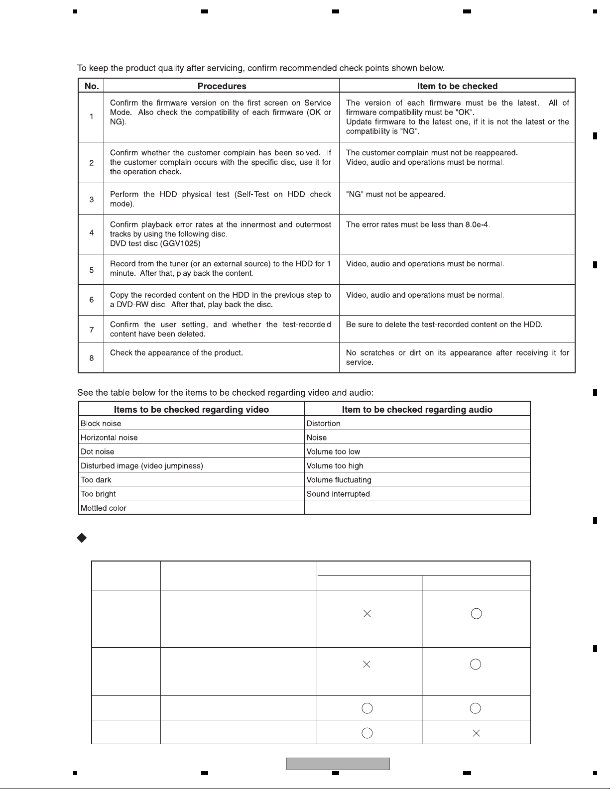
3.1 CHECK POINTS AFTER SERVICING
A
B
Necessary Procedure List When Replacing Assys
Following is the surely necessary procedures and the product state after changing, when replacing next ASSYs.
Replaced ASSY
MAIN ASSY
Necessary setting
User setting HDD contents
1. Model setting
2. LD power adjustment
3. CPRM setting
4. Firmware update
State after replacing
C
D
E
TURB ASSY
LOADER ASSY
HDD
56
1. Model setting
2. CPRM setting
3. Firmware update
1. LD power adjustment
1. CPRM setting
DVR-650H-K
F
23
7
8

1234
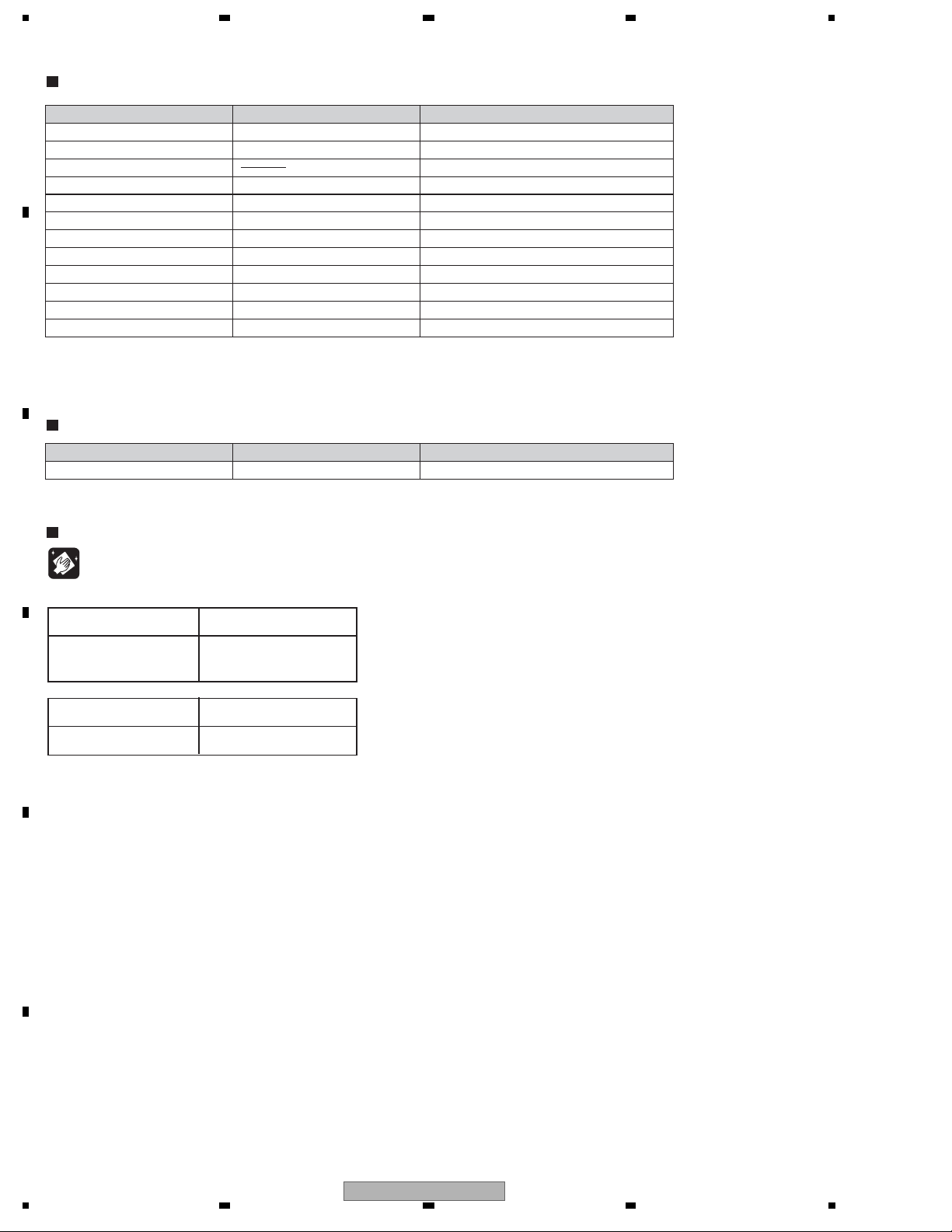
3.2 QUICK REFERENCE
Description of work Procedure Jigs
LD power adjustment [ESC]+[CX]+[1]+[0] GGF1381 : Service Remote Control Unit
A
GGV1054 : CD-ROM (CDT-313)
GGV1036 : DVD-ROM DL (DVDT-002)
GGV1278 : Blank DVD-R (That's DR-C12WTY5PA)
GGV1282 : Blank DVD-RW (JVC VD-W120XH5)
GGV1284 : Blank DVD-RAM (maxell DRM120C.1P5S)
ID input [ESC]+[STE
Firmware update [REC STOP]+[PLAY] Update disc
Version check [ESC]+[DISP] GGF1381 : Service Remote Control Unit
B
Error Rate Measurement [ESC]+[DISP]+[DIG/ANA] × twice GGF1381 : Service Remote Control Unit
HDD Check
Indication of VR-playback-related
error log
Indication of VR-recording-related
error log
Mode [ESC]+[CX]+[0]+[1] GGF1381 : Service Remote Control Unit
[ESC]+[DISP]+[5]+[DIG/ANA] GGF1381 : Service Remote Control Unit
[ESC]+[DISP]+[4]+[DIG/ANA] × 3times GGF1381 : Service Remote Control Unit
REO] GGF1381 : Service Remote Control Unit
GGV1305 : ID disc
Operation check disc (See remarks)
Remarks
Disc for check of
C
recording/playback operations
(Note)
When judging the drive quality,
make sure to use the operation
check disc.
D
How to read error rate
E
How to exit from Service Mode [ESC]
Operation check discs
(manufacturers and model numbers)
GGV1278 : Blank DVD-R
(That's DR-C12WTY5PA)
GGV1279 : Blank DVD-R DL
(MCM VHR21YD1)
GGV1280 : Blank DVD+R
(That's DR+120TY5PA)
GGV1281 : Blank DVD+R DL
(MCM VTR21N1)
GGV1189 : Blank DVD-RW
(JVC VD-W120N10)
GGV1282 : Blank DVD-RW [RW2]
(JVC VD-W120XH5)
GGV1283 : Blank DVD+RW
(RICOH D4RWV-S3CW)
GGV1284 : Blank DVD-RAM
(maxell DRM120C.1P5S)
GGV1036 : DVD-ROM DL
(DVDT-002)
Xe-Y
X.
Y: The bigger the better,
X X: The smaller the better
Error rate threshold
1.0e-3 or below
L0 : 1.0e-3 or below
L1 : 3.3e-3 or below
1.0e-3 or below
L0 : 1.0e-3 or below
L1 : 3.3e-3 or below
1.0e-3 or
below
1.0e-3 or below
1.0e-3 or below
1.0e-3 or below
L0/L1 : 8.0e-4 or below
F
24
1 234
DVR-650H-K

5678
3.3 PCB LOCATIONS
G
POWER SUPPLY
ASSY
E
VDEC ASSY
D
SERVICE MAIN ASSY
A
SERVICE TURB ASSY
B
SERVICE FLKY ASSY
A
F
SERVICE DVUB ASSY
NOTES:
Parts marked by "NSP" are generally unavailable because they are not in our Master Spare Parts List.
The mark found on some component parts indicates the importance of the safety factor of the part.
Therefore, when replacing, be sure to use parts of identical designation.
LIST OF ASSEMBLIES
Mark No. Description Part No.
NSP 1.. TUJB ASSY (DVR-650H-K, DVR-550H-K)VWM2437
NSP 1.. TUJB ASSY (DVR-450H-S)VWM2438
NSP 1.. FLKB ASSYVWM2434
FLKY ASSY KEYB ASSY
LOADER ASSY MAIN
C
SERVICE FRJB ASSY
HDD
2.. SERVICE TURB ASSY VXX3251
2.. SERVICE DVUB ASSY VXX3231
(DVR-650H-K, DVR-550H-K Only)
2.. SERVICE FLKY ASSYVXX3226
3.. FLKY ASSY
3.. KEYB ASS
Y
2.. SERVICE FRJB ASSYVXX3227
1.. VDEC ASSYVWV2304
1.. SERVICE MAIN ASSY (DVR-650H-K, DVR-550H-K)VXX3242
1.. SERVICE MAIN ASSY (DVR-450H-S) VXX3240
1.. POWER SUPPLY ASSYVWR1408
B
C
D
DVR-650H-K
56
E
F
25
7
8
1234
3.4 JIGS LIST
Jigs List
A
Service Remote Control Unit GGF1381
DVD Te s t Disc (DVD-Video)
DVD Recorder Data Disc
FFC Cable (40p) GGD1436 Diagnosis of MAIN Assy
FFC Cable (28p) GGD1517 Diagnosis of MAIN Assy
CD-ROM GGV1054
DVD -ROM DL GGV1036
Blank DVD-R GGV1278 LD Power Adjustment
Blank DVD-RW GGV1282 LD Power Adjustment
Blank DVD-RAM GGV1284 LD Power Adjustment
Disc Ejection Rod GGF1529 Emergency Disc Ejection
B
USB Cable GGD1145 USB Check Mode
(*) Be sure to use the latest disc (Type 2).
In Feb, 2007, the latest disc is GGV1305.
Name Jig No.Remarks
Adjustment, diagnosis
Check of DVD-Video
Diagnosis (ID data setting)
LD Power Adjustment
LD Power Adjustment
Ty p e 2
GGV1025
(*)
Lubricants and Glues List
Name Lubricants and Glues No.Remarks
Hanarl GEM1041
C
refer to "9.3 FRONT PANEL SECTION"
Cleaning
Before shipping out the product, be sure to clean the following positions by using the prescribed cleaning tools:
Position to be cleaned Cleaning tools
Pickup lenses Cleaning liquid : GEM1004
Cleaning paper : GED-008
Position to be cleaned Cleaning tools
D
Fans Cleaning paper : GED-008
E
F
26
1 234
DVR-650H-K

5678
A
B
C
D
E
DVR-650H-K
56
F
27
7
8

1234
C
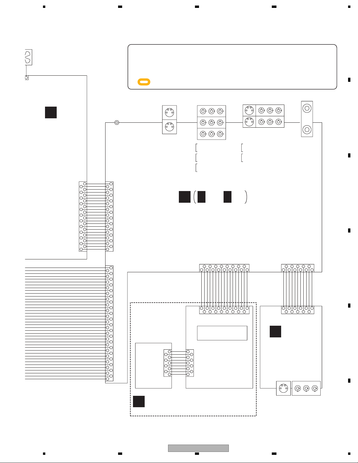
4. BLOCK DIAGRAM
4.1 OVERALL WIRING DIAGRAM
A
FR
50 50
FD
49
TR
48 48
TD
47
SCLK
46
SDIO
45
SEN
44
VPP
43
RESET
42
VD3V
41
TEMP
40
RSET
39
W1SET
38
W2SET
37
W3SET
36
LDDEN
35
OSCEN-
34
B
C
D
E
32 32
30
28
26
24
22
P. U .
20
18
16
14
12
10
8
6
4
2
FRONT
SPDLSTEPPER
OSCEN+
33
W1ENW1EN+
31
W3ENW3EN+
29
W2ENW2EN+
27
V05V
V05V
25
OSC
NT
GND0
23
GND0
HFGAIN
21
DVD/CD
GNDA
19
FMO-
FMO+
17
VA5V
SW2
15
M3
M2
13
M1
M4
11
VREFPD
RF+
9
GNDA
RF-
7
VA5V
S3
5
S2
S1
3
S4
SW1
1
LPS2
5
GNDD
4
LPS1
3
BLACK
2
RED
1
ST2+
4
ST2-
3
ST1-
2
ST1+
1
VCC
12
HU+
11
HU-
10
HV+
9
HV-
8
HW+
7
HW-
6
HB
5
U
4
V
3
W
2
GNDD
1
CN101
49
47
46
45
44
43
42
41
40
39
38
37
36
35
34
33
31
30
29
28
27
26
25
24
23
22
21
20
19
18
17
16
15
14
13
12
11
10
9
8
7
6
5
4
3
2
1
CN601
5
4
3
2
1
CN502
4
3
2
1
CN501
12
11
10
9
8
7
6
5
4
3
2
1
DIGITAL
AUDIO OUT
COAXIAL
JA5701
HDMI
JA5801
D
CN5604
1
2
3
4
5
6
To HDD
7
CN4501
1
2
3
4
5
6
7
8
9
10
11
12
13
CN4701
1
2
3
4
5
6
7
8
9
10
11
12
13
14
15
16
17
18
19
20
21
22
23
24
25
26
27
28
D 1/5- D 5/5
HDD
160GB:VXF1137
(DVR-550H-K,
DVR-450H-S)
250GB:VXF1131
(DVR-650H-K)
2756
4
1
3
GND
TXP
TXN
GND
RXN
RXP
GND
VDX1014-
VDX1016-
EV+5.8V
GNDD
SW+1.53V
SW+1.53V
GNDD
SW+3.33V
SW+3.33V
GNDD
V+12V
GND
V+5M
GNDM
V+12M
PF13PP-S17
GND
SPDIF
GND
ABCKI
ADATA
ALRCKI
GND
STREAM_0
STREAM_1
STREAM_2
STREAM_3
STREAM_4
STREAM_5
STREAM_6
STREAM_7
GND
VCLKI
GND
GND (RFE)/XLL
XRESET
GND
RX1
TX1
GND
SCL_VDEC
SDA_VDEC
GND
AT/XDT
43
12
VKP2389-
SW+12V
GND
GND
SW+5V
SERVICE MAIN ASSY
(VXX3242 : DVR-650H-K, DVR-550H-K)
(VXX3240 : DVR-450H-S)
DVR-650H-K, DVR-550H-K Only
CN5101
21364
5
SERVICE
LOADER
MAIN
VKP2390-
TPAN
TPAP
213654
CN901
GND
GND
TPBP
TPBN
F
CN902
CN5201
123674589
GND
USBDP1
USBDM1
13
26
JA903JA901
10
VKP2391-
GND
GND
GND
V+5USB
USBVFB
USBDP2
USBDM2
745
9
108
F
JA902
AC POWER CORD
1
2
CN101
LIVE
(NEUTRAL)
AC-INLET
CN204
1
432
CN201
1
2
3
4
5
6
711 9
10 8
13
12
POWER
G
SUPPLY
ASSY
(VWR1408)
CN202
VDA2164-
CN2301
SERVICE DVUB ASSY
(VXX3231)
1
2
3
4
5
6
7
8
9
10
11
12
1
12
201816
222142624 2881046
23 2721 25 2919171511 139573
3937353331
40363432 3830
P_CONT
SW+3.3V
GND
SW+3.3V
GND
EV+5.8V
EV+5.8V
GND
EV+12.1V
GND
SW+1.5V
SW+1.5V
VKP2397-
FAN MOTOR
VXM1125-
CN105
12
11
10
9
8
7
6
5
4
3
2
1
28
27
26
25
24
23
22
21
20
19
18
17
16
15
14
13
12
11
10
9
8
7
6
5
4
3
2
1
HPD
DDC_SW1
DSCL
CEC
DSDA
HST_TO_M
ASCK
DAT_TO_M
HSM_TO_T
DAM_TO_T
XRST1
MRST
P_CONT2
GND
L_IN
GND
R_IN
AMUTE
R_OUT
GNDA
L_OUT
GND
B_IN
GND
G_IN
GND
C/R_IN
GND
Y_IN
GND
C_OUT
GND
Y_OUT
GND
CB_OUT
GND
CR_OUT
GND
YP_OUT
X525P
VDA2159-
FAN-
FAN+
2
1
CN203
CN104
E
VDE
(VWV2
28
DVR-650H-K
1 234
5678
FAN
125-
TOR
When ordering service parts, be sure to refer to "EXPLODED VIEWS and PART S
A
LIST" or "PCB PAR T S LIST".
-
2
N203
E
VDEC ASSY
(VWV2304)
CN106
104
-
2
4
6
8
10
12
14
16
18
20
22
24
1
3
5
7
9
11
13
15
17
19
21
23
GND
FANGND
P-CONT
EV+5.8V
GND
EV+5.8V
GND
EV+12.1V
GND
NC
P-CONT2
NC
NC
NC
GND
Y_IN
GND
B_IN
GND
G_IN
GND
C/R_IN
GND
VDA2165-
CN302
24
23
22
21
20
19
18
17
16
15
14
13
12
11
10
9
8
7
6
5
4
3
2
1
CN101
40
39
38
37
36
35
34
33
32
31
30
29
28
27
26
25
24
23
22
21
20
19
18
17
16
15
14
13
12
11
10
9
8
7
6
5
4
3
2
1
SR IN
JA701
The > mark found on some component parts indicates the importance of the safety
factor of the part. Therefore, when replacing, be sure to use parts o
f identical
designation.
: The power supply is shown with the marked box.
S-VIDEO
JA401
S OUT1
OUT
S OUT2 OUT
COMPONENT
A
OUTPUT
JA402
R
L
VIDEO
AUDIO
IN
IN
CbCr
Y
A 1/3- A 3/3
INPUT
JA403
S-VIDEO
R
L
VIDEO
AUDIO
U/V IN/OUT
U601
SERVICE TURB ASSY
(VXX3251)
CN105 CN106
21436
59
IR
GND
V+5F
FLPON
V+12R1E
VDA2163-
17 13 1115 7951 11351379
16 1014 6 4 2 248610
CN101 CN301
12
108
16
FLSTB
14
GND
LED_P_ON
8
KEY3
KEY2
KEY1
LED_DIVX
LED_PLTV
LED_A_TV
LED_D_TV
711 17
FLCLK
FLDATA
12
11513
345627891011
2C
GND2YGND2VGND2RGND2LGND
SDET2
VDA2162-
SERVICE
KEYB
ASSY
CN201
2
4
6
8
1
3
5
7
9
KEY1
LED_A_TV
LED_D_TV
LED_PLTV
LED_DIVX
LED_COPY
GND
V+5F
GND
CN102
FLKY ASSY
1
2
3
4
5
6
7
8
9
FL TUBE
C
FRJB
ASSY
(VXX3227)
COMPOSITE
S-VIDEO
AUDIO (L/R)
B
C
D
E
SERVICE FLKY ASSY
B
(VXX3226)
DVR-650H-K
56
JA301 JA302
INPUT2
F
29
7
8
1234
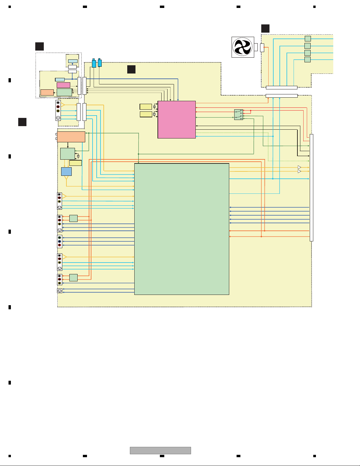
4.2 OVERALL BLOCK DIAGRAM
A
B
C
C
D
SERVICE
B
FLKY ASSY
FLKY
FL TUBE
INPUT 2
SERVICE
FRJB ASSY
Tuner
INPUT3
OUTPUT
COMPONENT OUT
INPUT1
OUTPUT
KEY SW
IR Receiver
FL DRIVER
PT6315
JA403 (1/2)
JA402 (2/3)
JA401 (2/2)
JA402 (3/3)
JA403 (2/2)
JA402 (1/3)
JA401 (1/2)
KEYB
KEY SW
CN201
CN102
U601
VHF/UHF Tuner
IC601
Multi sound
Decoder
MSP3417G
18.432MHz
LPF
MUTE
Y
Cb
Cr
MUTE
SR
IR Blaster
JA751
JA701
IR
CN101
CN105
CN301
CN106
L2_L&RIN
2VIN
Y2IN
C2IN
TU_L&RIN
TU_VIN
L3_L&RIN
3VIN
Y3IN
C3IN
1VOUT
Y1OUT
C1OUT
L1_L&RIN
1VIN
Y1IN
C1IN
2VOUT
Y2OUT
C2OUT
SERVICE TURB ASSY
A
15MHz
32.768kHz
KEY1/KEY2/KEY3
IR_B
SEL_IR
FLDATA
FLCLK
FLSTB
Tuner Control uCON
42,43
91,92
14
7
9
86,87
18
84,85
16
3
5
32
36
34
40
38
39
89,90
12
100
1
26
30
28
IC101
PMC022A8
IC401
RENESAS
HA118326PF
FANCTL
HOTPLUG
CEC0
SCL0/SCA0
ASCK/DAM_TO_T/HSM_TO_T
DAT_TO_M/HST_TO_M
XRST1
TEXTV
80
79
61
59
55
57
51
53
52
77
76
IC104
TC7MB3257FK
L_IN
R_IN
Y_IN
C_IN
Y_OUT
C_OUT
Y/G_OUT
Cb/B_OUT
Cr/R_OUT
L_OUT
R_OUT
CEC
DDC SDL/DDC SDA
SDL/SDA
VDEC ASSY
E
Y_IN
CN103
Y_IN
C_IN
FAN-
CN106
CN302
C_IN
IC402
BA4560RF
LPF
ATT
LPF
ATT
LPF
ATT
LPF
ATT
CN101
E
F
30
DVR-650H-K
1 234
 Loading...