

Page 1
DVR-540H-S
DVR-440H-S
DVD RECORDER
Discover the benefits of registering your product online at
(www.pioneer-eur.com)
Operating Instructions
www.pioneer.co.uk
®
®
Page 2
Thank you for buying this Pioneer product.
Please read through these operating instructions so you will know how to operate your model properly.
After you have finished reading the instructions, put them away in a safe place for future reference.
IMPORTANT
CAUTION
RISK OF ELECTRIC SHOCK
DO NOT OPEN
The lightning flash with arrowhead symbol,
within an equilateral triangle, is intended to
alert the user to the presence of uninsulated
"dangerous voltage" within the product's
enclosure that may be of sufficient
magnitude to constitute a risk of electric
shock to persons.
CAUTION:
TO PREVENT THE RISK OF ELECTRIC
SHOCK, DO NOT REMOVE COVER (OR
BACK). NO USER-SERVICEABLE PARTS
INSIDE. REFER SERVICING TO QUALIFIED
SERVICE PERSONNEL.
The exclamation point within an equilateral
triangle is intended to alert the user to the
presence of important operating and
maintenance (servicing) instructions in the
literature accompanying the appliance.
D3-4-2-1-1_En-A
WARNING
This equipment is not waterproof. To prevent a fire
or shock hazard, do not place any container filed
with liquid near this equipment (such as a vase or
flower pot) or expose it to dripping, splashing, rain
or moisture.
CAUTION
This product is a class 1 laser product, but this product
contains a laser diode higher than Class 1.
To ensure continued safety, do not remove any covers or
attempt to gain access to the rear of the product.
Refer all servicing to qualified personnel.
The following caution labels appear on your unit.
Location: top and rear of the unit
CLASS 3B VISIBLE AND INVISIBLE LASER RADIATION WHEN OPEN, AVOID EXPOSURE TO THE BEAM.
CAUTION
RADIATIONS LASER VISIBLES ET INVISIBLES DE CLASSE 3B QUAND OUVERT. ÉV ITEZ TOUT EXPOSITION AU FAISCEAU.
ATTENTION
KLASSE 3B SYNLIG OG USYNLIG LASERSTRÅLING VED ÅBNING. UNDGÅ UDSÆTTELSE FOR STRÅLING.
ADVARSEL
KLASS 3B SYNLIG O CH OSYNLIG LASER STRÅLNING NÄR DENNA DEL ÄR ÖPPNAD. UNDVIK AT T U TSÄ TTA DIG FÖR STRÅLEN.
VARNING
BEI GEÖFFNETER ABDECKUNG IST SICHTB ARE UND UN SICH TBARE LASERSTRAHLUNG DER KLASSE 3B IM GERÄTEINNEREN VORHANDEN .
VORSICHT
NICHT DEM LASERSTRAHL AUSSETZEN!
CUANDO SE ABRE HAY RADIACIÓN LÁSER DE CLASE 3B VISIBLE E INV IS IB LE . E VI T E LA EX PO SIC IÓN A LOS RAYO S LÁSER.
PRECAUCIÓN
AVATTAESSA OLET ALTTIINA NÄKYVÄLLE JA NÄKYMÄTTÖMÄLLE LUOKAN 3B LASERSÄTEILYLLE. ÄLÄ KATSO SÄTEESEEN.
VARO!
This product complies with the Low Voltage Directive
(73/23/EEC, amended by 93/68/EEC), EMC Directives
(89/336/EEC, amended by 92/31/EEC and
93/68/EEC).
D3-4-2-1-3_A_En
D3-4-2-1-9a_En
WARNING
Before plugging in for the first time, read the following
section carefully.
The voltage of the available power supply differs
according to country or region. Be sure that the
power supply voltage of the area where this unit
will be used meets the required voltage (e.g., 230 V
or 120 V) written on the rear panel.
VRW2262 - A
D3-4-2-1-4_A_En
D3-4-2-1-8_B_En
WARNING
To prevent a fire hazard, do not place any naked
flame sources (such as a lighted candle) on the
equipment.
D3-4-2-1-7a_A_En
If you want to dispose this product, do not mix it with general household waste. There is a separate collection system for used
electronic products in accordance with legislation that requires proper treatment, recovery and recycling.
Private households in the 25 member states of the EU, in Switzerland and Norway may return their used electronic products free of charge to
designated collection facilities or to a retailer (if you purchase a similar new one).
For countries not mentioned above, please contact your local authorities for the correct method of disposal.
By doing so you will ensure that your disposed product undergoes the necessary treatment, recovery and recycling and thus prevent potential
negative effects on the environment and human health.
K058_En
Page 3
Operating Environment
Operating environment temperature and humidity:
+5 ºC to +35 ºC (+41 ºF to +95 ºF); less than 85 %RH
(cooling vents not blocked)
Do not install this unit in a poorly ventilated area, or in
locations exposed to high humidity or direct sunlight (or
strong artificial light)
D3-4-2-1-7c_A_En
VENTILATION CAUTION
When installing this unit, make sure to leave space
around the unit for ventilation to improve heat
radiation (at least 10 cm at top, 10 cm at rear, and
10 cm at each side).
WARNING
Slots and openings in the cabinet are provided for
ventilation to ensure reliable operation of the
product, and to protect it from overheating. To
prevent fire hazard, the openings should never be
blocked or covered with items (such as newspapers,
table-cloths, curtains) or by operating the
equipment on thick carpet or a bed.
D3-4-2-1-7b_A_En
CAUTION
The STANDBY/ON switch on this unit will not
completely shut off all power from the AC outlet.
Since the power cord serves as the main disconnect
device for the unit, you will need to unplug it from
the AC outlet to shut down all power. Therefore,
make sure the unit has been installed so that the
power cord can be easily unplugged from the AC
outlet in case of an accident. To avoid fire hazard,
the power cord should also be unplugged from the
AC outlet when left unused for a long period of time
(for example, when on vacation).
D3-4-2-2-2a_A_En
This product is for general household purposes. Any
failure due to use for other than household purposes
(such as long-term use for business purposes in a
restaurant or use in a car or ship) and which
requires repair will be charged for even during the
warranty period.
K041_En
If the AC plug of this unit does not match the AC
outlet you want to use, the plug must be removed
and appropriate one fitted. Replacement and
mounting of an AC plug on the power supply cord of
this unit should be performed only by qualified
service personnel. If connected to an AC outlet, the
cut-off plug can cause severe electrical shock. Make
sure it is properly disposed of after removal.
The equipment should be disconnected by removing
the mains plug from the wall socket when left
unused for a long period of time (for example, when
on vacation).
Replacement and mounting of an AC plug on the power supply cord of this unit should be performed only by qualified
service personnel.
IMPORTANT: THE MOULDED PLUG
This appliance is supplied with a moulded three pin mains plug for your safety and convenience. A 5 amp fuse is fitted in this plug. Should the
fuse need to be replaced, please ensure that the replacement fuse has a rating of 5 amps and that it is approved by ASTA or BSI to BS1362.
Check for the ASTA mark or the BSI mark on the body of the fuse.
If the plug contains a removable fuse cover, you must ensure that it is refitted when the fuse is replaced. If you lose the fuse cover the plug
must not be used until a replacement cover is obtained. A replacement fuse cover can be obtained from your local dealer.
If the fitted moulded plug is unsuitable for your socket outlet, then the fuse shall be removed and the plug cut off and disposed of
safely. There is a danger of severe electrical shock if the cut off plug is inserted into any 13 amp socket.
If a new plug is to be fitted, please observe the wiring code as shown below. If in any doubt, please consult a qualified electrician.
WARNING : THIS APPARATUS MUST BE EARTHED.
IMPORTANT: The wires in this mains lead are coloured in accordance with the following code:
Green & Yellow : Earth Blue : Neutral Brown : Live
As the colours of the wires in the mains lead of this appliance may not correspond with the coloured markings identifying the terminals in
your plug, proceed as follows ;
The wire which is coloured GREEN-AND-YELLOW must be connected to the terminal in the plug which is marked with the letter E or
by the earth symbol or coloured GREEN or GREEN-AND-YELLOW.
The wire which is coloured BLUE must be connected to the terminal which is marked with the
letter N or coloured BLACK.
The wire which is coloured BROWN must be connected to the terminal which is marked with the
letter L or coloured RED.
How to replace the fuse: Open the fuse compartment with a screwdriver and replace the fuse.
D3-4-2-2-1a_A_En
Handle the power cord by the plug. Do not pull out the
plug by tugging the cord and never touch the power
cord when your hands are wet as this could cause a
short circuit or electric shock. Do not place the unit, a
piece of furniture, etc., on the power cord, or pinch the
cord. Never make a knot in the cord or tie it with other
cords. The power cords should be routed such that they
are not likely to be stepped on. A damaged power cord
can cause a fire or give you an electrical shock. Check
the power cord once in a while. When you find it
damaged, ask your nearest PIONEER authorized
service center or your dealer for a replacement.
S002_En
D3-4-2-1-2-1_B_En
POWER-CORD CAUTION
Page 4

Contents
01 Before you start
What’s in the box . . . . . . . . . . . . . . . . . . . 6
Putting the batteries in the
remote control. . . . . . . . . . . . . . . . . . . . . . 6
Using the remote control. . . . . . . . . . . . . . 6
Disc / content format playback
compatibility . . . . . . . . . . . . . . . . . . . . . . . 7
About the internal hard disk drive . . . . . . 12
Symbols used in this manual . . . . . . . . . 13
02 Connecting up
Rear panel connections. . . . . . . . . . . . . . 14
Front panel connections . . . . . . . . . . . . . 15
Easy connections . . . . . . . . . . . . . . . . . . 16
Using other types of audio/video output .17
Connecting to a cable box, satellite
receiver or digital terrestrial receiver . . . . 18
Connecting an external decoder box (1) .20
Connecting an external decoder box (2) .21
Connecting to an AV amplifier/receiver . . 22
Connecting other AV sources . . . . . . . . . 23
Plugging in . . . . . . . . . . . . . . . . . . . . . . . 23
03 Controls and displays
Front panel . . . . . . . . . . . . . . . . . . . . . . . 24
Display . . . . . . . . . . . . . . . . . . . . . . . . . . 25
Remote control . . . . . . . . . . . . . . . . . . . . 26
05 Using the GUIDE Plus+®
electronic program guide
The GUIDE Plus+® system . . . . . . . . . . 36
Using the GUIDE Plus+® system . . . . . 37
Areas . . . . . . . . . . . . . . . . . . . . . . . . . . . 39
GUIDE Plus+® FAQ and
troubleshooting . . . . . . . . . . . . . . . . . . . 49
06 Recording
About DVD recording . . . . . . . . . . . . . . . 52
About HDD recording. . . . . . . . . . . . . . . 53
Recorded audio . . . . . . . . . . . . . . . . . . . 54
Restrictions on video recording . . . . . . . 54
Using the built-in TV tuner . . . . . . . . . . . 55
Setting the picture quality/recording
time . . . . . . . . . . . . . . . . . . . . . . . . . . . . 56
Basic recording from the TV . . . . . . . . . . 57
Pause Live TV . . . . . . . . . . . . . . . . . . . . . 58
Setting a timer recording . . . . . . . . . . . . 59
Timer recording FAQ . . . . . . . . . . . . . . . 62
Simultaneous recording and playback
(Chase Play) . . . . . . . . . . . . . . . . . . . . . . 63
Recording from an external
component. . . . . . . . . . . . . . . . . . . . . . . 63
Playing your recordings on other DVD
players . . . . . . . . . . . . . . . . . . . . . . . . . . 64
Initializing recordable DVD discs . . . . . . 66
04 Getting started
Switching on and setting up . . . . . . . . . . 29
Setting up the GUIDE Plus+® system . . 32
4
En
07 Playback
Introduction . . . . . . . . . . . . . . . . . . . . . . 67
Basic playback . . . . . . . . . . . . . . . . . . . . 67
Using the Disc Navigator to browse
the contents of a disc . . . . . . . . . . . . . . . 72
Scanning discs. . . . . . . . . . . . . . . . . . . . 73
Playing in slow motion . . . . . . . . . . . . . . 74
Frame advance/frame reverse . . . . . . . . 74
The Play Mode menu . . . . . . . . . . . . . . . 74
Page 5

Displaying and switching subtitles
Switching DVD and DivX soundtracks
Switching audio channels
Switching camera angles
Displaying disc information on-screen
. . . . . . . . . . . . 78
. . . . . . . . . . . . 79
. . . . . 77
. . . 78
. . 79
14 The Initial Setup menu
Using the Initial Setup menu
Selecting other languages for language
. . . . . . . . . . . . . . . . . . . . . . . . . 128
options
. . . . . . . . 116
08 Editing
Editing options
The Disc Navigator screen
. . . . . . . . . . . . . . . . . . . . 81
. . . . . . . . . . . . 82
09 Copying and backup
Introduction
One Touch Copy
Using Copy Lists
Using disc backup
. . . . . . . . . . . . . . . . . . . . . . 94
. . . . . . . . . . . . . . . . . . . 95
. . . . . . . . . . . . . . . . . . . 96
. . . . . . . . . . . . . . . . . 102
10 Using the Jukebox
Copying music to the HDD
Playing music from the Jukebox
Editing Jukebox albums
. . . . . . . . . . 104
. . . . . . . . . . . . 106
11 The PhotoViewer
Locating JPEG picture files
Playing a slideshow
. . . . . . . . . . 107
. . . . . . . . . . . . . . . . 107
12 The Disc Setup menu
Basic settings
Initialize settings
Finalize settings
Optimize HDD
Initialize HDD
. . . . . . . . . . . . . . . . . . . . 109
. . . . . . . . . . . . . . . . . . 110
. . . . . . . . . . . . . . . . . . . 110
. . . . . . . . . . . . . . . . . . . . 111
. . . . . . . . . . . . . . . . . . . . 111
. . . . . . 105
15 Additional information
Minimum copying times
Manual recording modes
Troubleshooting
On-screen displays and recorder
displays
Language code list
Country/Area code list
Screen sizes and disc formats
Handling discs
Cleaning the pickup lens
Condensation
Hints on installation
Moving the recorder
Resetting the recorder
Specifications. . . . . . . . . . . . . . . . . . . . 142
. . . . . . . . . . . . . . . . . . . . . . . . 135
. . . . . . . . . . . . . . . . . . . 140
. . . . . . . . . . . . . . . . . . . . 141
. . . . . . . . . . . . 129
. . . . . . . . . . . 130
. . . . . . . . . . . . . . . . . . 131
. . . . . . . . . . . . . . . . 137
. . . . . . . . . . . . . 138
. . . . . . . 139
. . . . . . . . . . . 140
. . . . . . . . . . . . . . . 141
. . . . . . . . . . . . . . . 141
. . . . . . . . . . . . . 141
13 The Video Adjust menu
Setting the picture quality for TV and
external inputs
Setting the picture quality for disc
playback
. . . . . . . . . . . . . . . . . . . 112
. . . . . . . . . . . . . . . . . . . . . . . . 114
5
En
Page 6
01
Before you start
Chapter 1
Before you start
What’s in the box
Please confirm that the following
accessories are in the box when you open it.
• Remote control
• AA/R6P dry cell batteries x 2
• Audio/video cable (red/white/yellow)
• G-LINK™ cable
• RF antenna cable
• Power cable
• These operating instructions
• Warranty card
Putting the batteries in the
remote control
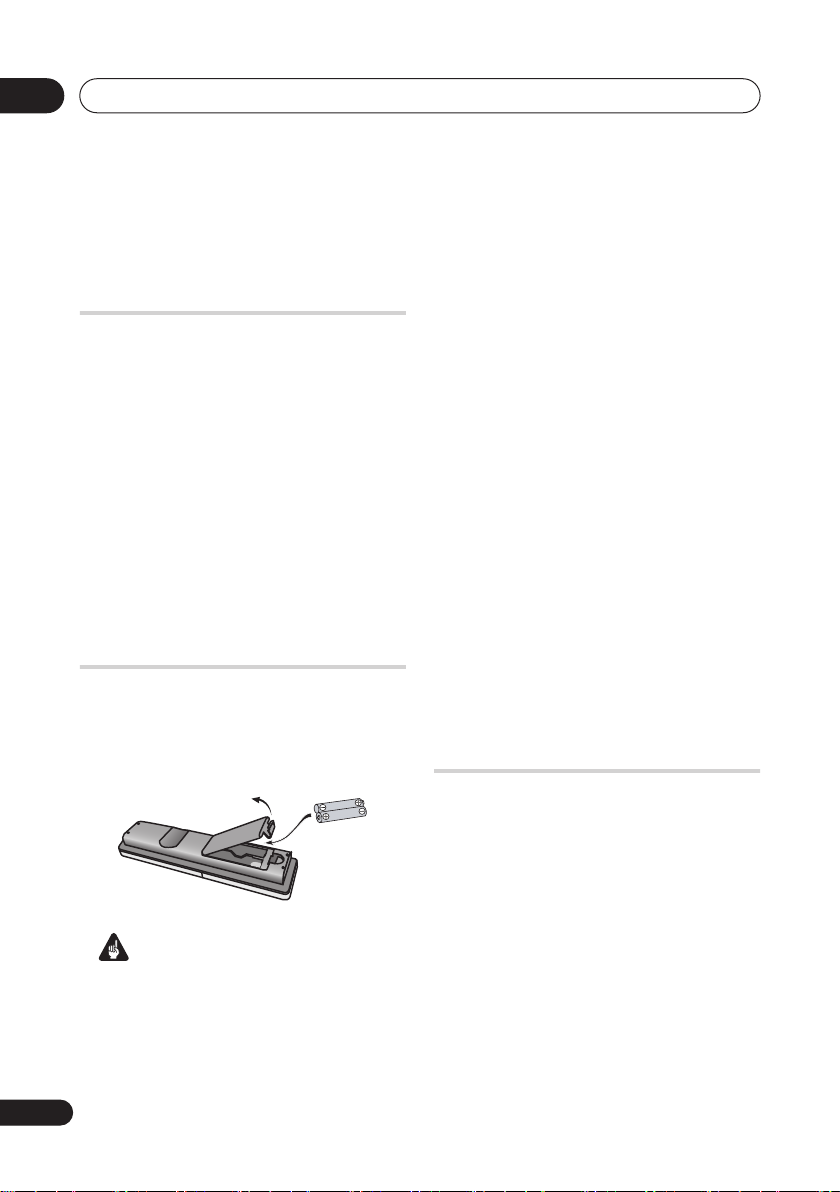
1 Insert two AA/R6P batteries into the
battery compartment following the
indications (
compartment.
Incorrect use of batteries can result in
hazards such as leakage and bursting.
Please observe the following:
• Don’t mix new and old batteries
together.
,
Important
) inside the
• Don’t use different kinds of batteries
together—although they may look
similar, different batteries may have
different voltages.
• Make sure that the plus and minus ends
of each battery match the indications in
the battery compartment.
• Remove batteries from equipment that
isn’t going to be used for a month or
more.
• When disposing of used batteries,
please comply with governmental
regulations or environmental public
instruction’s rules that apply in your
country or area.
Do not use or store batteries in direct sunlight or
other excessively hot place, such as inside a car or
near a heater. This can cause batteries to leak,
overheat, explode or catch fire. It can also reduce the
life or performance of batteries.
WARNING
D3-4-2-3-3_En
Using the remote control
Please keep in mind the following when
using the remote control:
• Make sure that there are no obstacles
between the remote and the remote
sensor on the unit.
• Remote operation may become
unreliable if strong sunlight or
fluorescent light is shining on the unit’s
remote sensor.
• Remote controllers for different devices
can interfere with each other. Avoid
using remotes for other equipment
located close to this unit.
6
En
Page 7
Before you start
01
• Replace the batteries when you notice a
fall off in the operating range of the
remote.
• When the batteries run down or you
change the batteries, the remote control
mode is reset to Recorder 1. See Remote
Control Mode on page 126.
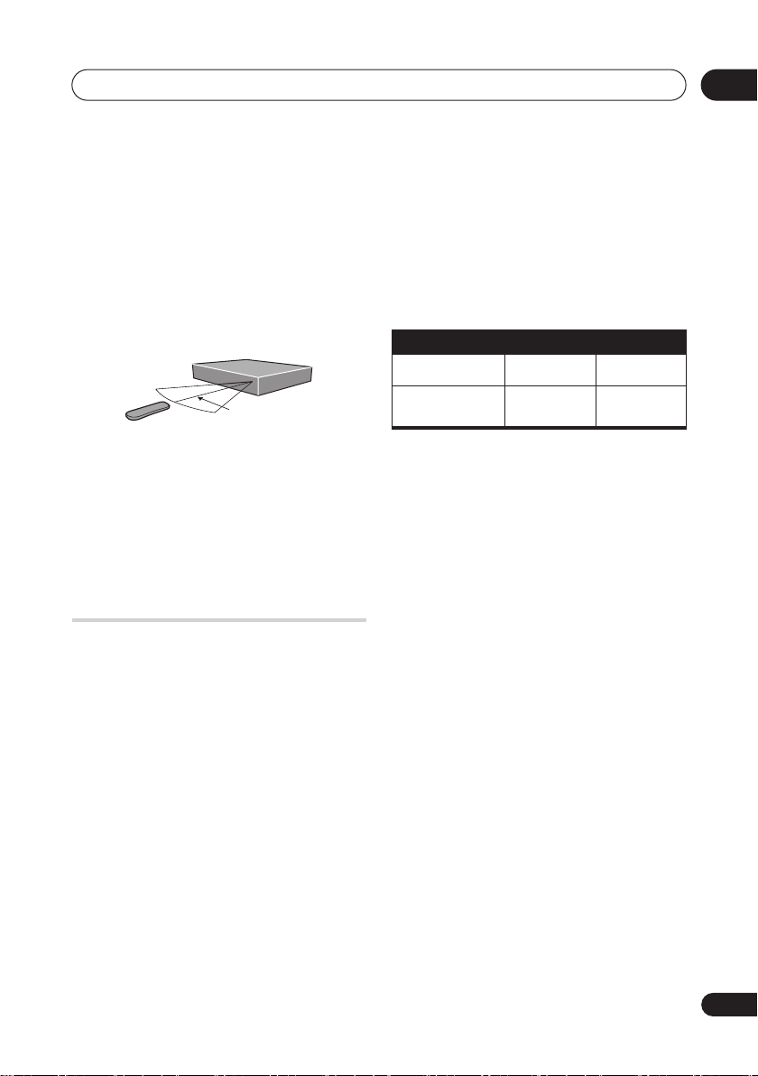
• Use within the operating range in front of
the remote control sensor on the front
panel, as shown.
7 m
• You can control this recorder using the
remote sensor of another Pioneer
component using the CONTROL IN jack
on the rear panel. See Rear panel
connections on page 14 for more
information.
Disc / content format
playback compatibility
Compatible media
• DVD-RW ver. 1.1 / 1 x / 1 x to 2 x, ver. 1.2
/ 2 x to 4 x / 2 x to 6 x
• DVD-R ver. 2.0 /1 x / 1 x to 4 x /
1 x to 8 x / 1 x to 16 x, ver. 2.1 / 1 x to 8 x /
1 x to 16 x
• DVD+RW 1 x to 2.4 x / 1 x to 4 x / 3.3 x to
8 x
• DVD+R 1 x to 2.4 x / 1 x to 4 x / 1 x to 8 x
/ 1 x to 16 x
• DVD-RAM ver. 2.0 / 2 x, ver. 2.1 / 2 x / 2 x
to 3 x / 2 x to 5 x, ver. 2.2 / 2 x / 2 x to 3 x /
2 x to 5 x
• DVD-R DL ver. 3.0 / 2 x to 4 x
• DVD+R DL 2.4 x / 2.4 x to 8 x
Note that older models of DVD recorders
and DVD writers may reject DVD-RW ver. 1.2
discs and/or corrupt the data on the disc. If
you want to share DVD-RW discs between
this recorder and an older recorder/writer,
we recommend using ver. 1.1 discs.
The following table shows older Pioneer DVD
recorders’ limited compatibility with DVDRW ver. 1.2 discs.
Model Playable Recordable
DVR-7000
DVR-3100 /
DVR-5100H
1
Discs should be finalized in this recorder before
playing. Unfinalized VR mode and Video mode discs
may not play.
2
Cannot read the CPRM information will show in
the display when you load a disc. However, this will not
affect playback.
3
Copy-once protected disc titles will not play.
Yes
Yes
1,2,3
No
1
No
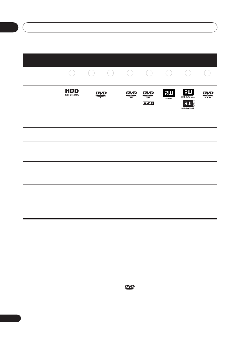
DVD/HDD Recording and playback
compatibility
This recorder can play and record all the
currently popular DVD disc types, as well as
providing HDD functionality. The table below
shows some specific compatibility
differences between the different disc types.
En
7
Page 8
01
Before you start
Marks used in this
manual
Logos
Re-recordable /
Erasable
Editing of recorded
programs
Recording of Copyonce protected
material
Playback in other
players/recorders
Chase play
16:9 and 4:3 program recording
Bilingual broadcast
recording of both
audio channels
HDD DVD-R DVD-RW DVD+R
HDD DVD (VR) DVD (Video) DVD ( VR) DVD (Video) DVD+R DVD+RW DVD-RAM
*1 *1 *2 *13, 16
*4 *4 *4 *4
n/a
*10, 11
*3
*5
*12
*11
*3
*6
*12
*7
*11
*3
*6
*6, 15
DVD
+RW
*8
*14
DVDRAM
*12
*9
*11
Notes to table
*1 Must be initialized for VR mode recording (page 110)
*2 Must be initialized for Video mode recording
(page 110)
*3 Erasable, but free space does not increase
*4 Cannot erase sections, edit chapters or use playlist
editing
*5 Must be compatible with DVD-R(VR) playback
*6 Finalize using this recorder (may not playback in
some units) (page 64)
*7 Must be compatible with DVD-RW(VR) playback
*8 Must be compatible with DVD+RW playback
*9 Must be compatible with DVD-RAM playback
*10 Only when HDD Recording Format is set to Video
Mode Off (page 124)
*11 Only when the recording mode is not set to LPCM
8
En
*12 CPRM-compatible discs only
*13 Take the disc out of the cartridge before use. Only
Matsushita and Maxell discs have been tested to work
reliably with this recorder. Discs from other makers may
become unusable when recorded or edited.
*14 Erasing a title does not increase the available
recording time, nor increase the number of recordable
titles left.
*15 Must be compatible with DVD+R playback
*16 Depending on the disc, it may have to be initialized
before it can be recorded (page 110). In this case,
initialization will take about 1 hour.
is a trademark of DVD Format/Logo
Licensing Corporation.
Page 9
Before you start
01
Using DVD-R DL/DVD+R DL discs
DVD-R DL (dual-layer) and DVD+R DL
(double-layer) discs contain two recordable
layers on a single side, giving about 1.8
times the recording capacity of a
conventional single-layer disc. This unit can
record to both DVD-R DL and DVD+R DL
discs.
• If you intend to play DVD-R DL (Video
mode) or DVD+R DL discs recorded on
this unit on other DVD recorders/players,
you must finalize them. (Note that some
DVD recorders/players may not play
even finalized DL discs.)
• Please read the information provided on
the disc packaging carefully before
purchasing DVD-R DL/DVDw+R DL
discs:
•
Confirm the disc version:
2 x to 4 x DVD-R discs.
•
Confirm the recording speed:
should be compatible with 2 x or 4 x
recording; DVD+R with 2.4 x to 8 x
recording.
• This logo indicates that the disc is a
DVD-R DL or DVD+R DL disc:
Use ver. 3.0 /
DVD-R
The non-DVD, audio side of the disc is not
compliant with the CD Audio specification
and therefore may not play.
It is possible that when loading or ejecting a
DualDisc, the opposite side to that being
played will be scratched. Scratched discs
may not be playable.
The DVD side of a DualDisc plays in this
product. DVD-Audio content will not play.
For more detailed information on the
DualDisc specification, please refer to the
disc manufacturer or disc retailer.
Other disc compatibility
In addition to DVD, this recorder is
compatible with a wide range of disc types
(media) and formats. Playable discs will
generally feature one of the following logos
on the disc and/or disc packaging. Note
however that some disc types, such as
recordable CD (and DVD), may be in an
unplayable format—see below for further
compatibility information.
Audio CD CD-R
Video CD
CD-RW
Super Video CD (Super VCD)
• Correct operation has been confirmed
for DVD-R DL discs (Ver. 3.0 / 2 x, 4 x)
produced by the following
manufacturers: Mitsubishi Kagaku
Media, Verbatim (as of March 2005).
About DualDisc playback
A DualDisc is a new two -sided disc, one side
of which contains DVD content –video,
audio, etc. –while the other side contains
non-DVD content such as digital audio
material.
CD-R/RW compatibility
This recorder cannot record CD-R or CD-RW
discs.
• Readable formats: CD-Audio, Video CD/
Super VCD, ISO 9660 CD-ROM*
containing MP3, WMA, JPEG or DivX
files.
*
ISO 9660 Level 1 or 2 compliant. CD
physical format: Mode1, Mode2 XA Form1.
Romeo and Joliet file systems are both
compatible with this recorder.
9
En
Page 10
01
Before you start
• Multi-session playback: Yes (except CDAudio and Video CD/Super VCD)
WMA (Windows Media Audio)
compatibility
• Unfinalized disc playback: CD-Audio
only
Compressed audio compatibility
• Compatible media: CD-ROM, CD-R,
CD-RW
• Compatible formats: MPEG-1 Audio
Layer 3 (MP3), Windows Media Audio
(WMA)
• Sampling rates: 32 kHz, 44.1 kHz or
48 kHz
• Bit-rates: Any (128 Kbps or higher
recommended)
• Variable bit-rate (VBR) MP3 playback:
Yes
• VBR WMA playback: No
• WMA encoder compatibility: Windows
Media Codec 8
(files encoded using
Windows Media Codec 9 may be playable
but some parts of the specification are not
supported; specifically, Pro, Lossless,
Voice and VBR)
• DRM (Digital Rights Management)
1
file
playback: No
• File extensions: .mp3, .wma (these must
be used for the recorder to recognize
MP3 and WMA files – do not use for
other file types)
• File structure: Up to 99 folders / 999 files
(if these limits are exceeded, only files
and folders up to these limits are
playable)
Note
1 DRM (digital rights management) copy protection is a technology designed to prevent unauthorized copying by
restricting playback, etc. of compressed audio files on devices other the PC (or other recording equipment) used
to record it. For detailed information, please see the instruction manuals or help files that came with your PC
(or other WMA recording equipment) and/or software.
The Windows Media® logo printed on the
box indicates that this recorder can playback
Windows Media Audio content.
WMA is an acronym for Windows Media
Audio and refers to an audio compression
technology developed by Microsoft
Corporation. WMA content can be encoded
by using Windows Media
®
Windows
Windows Media
XP, Windows Media® Player 9 or
®
®
Player for
Player 10 series.
Microsoft, Windows Media, and the Windows
logo are trademarks, or registered trademarks
of Microsoft Corporation in the United States
and/or other countries.
DivX video compatibility
DivX is a compressed digital video format
created by the DivX
Inc. This recorder can play DivX video files
burned on CD-R/RW/ROM discs. Keeping
the same terminology as DVD-Video,
individual DivX video files are called "Titles."
When naming files/titles on a CD-R/RW disc
prior to burning, keep in mind that by default
they will be played in alphabetical order.
®
video codec from DivX,
10
En
Page 11

Before you start
01
• Official DivX® Certified product.
• Plays all versions of DivX
(including DivX
playback of DivX
• File extensions: .avi and .divx (these
must be used for the recorder to
recognize DivX video files). Note that all
files with the .avi extension are recognized
as MPEG4, but not all of these are
necessarily DivX video files and therefore
may not be playable on this recorder.
• File structure: Up to 99 folders or 999
files.
DivX, DivX Certified, and associated logos are
trademarks of DivX, Inc. and are used under
license.
®
®
®
video
6) with standard
media files.
DivX® VOD content
DivX
In order to play DivX VOD (video on demand)
content on this recorder, you first need to
register the recorder with your DivX VOD
content provider. You do this by generating a
DivX VOD registration code, which you
submit to your provider.
Some DivX VOD content may only be
playable a fixed number of times. When you
load a disc containing this type of DivX VOD
content, the remaining number of plays is
shown on-screen and you then have the
option of playing the disc (thereby using up
one of the remaining plays), or stopping. If
you load a disc that contains expired DivX
VOD content (for example, content that has
zero remaining plays), the message Rental
Expired is displayed.
If your DivX VOD content allows an unlimited
number of plays, then you may load the disc
into your recorder and play the content as
often as you like, and no message will be
displayed.
Important
• DivX VOD content is protected by a DRM
(Digital Rights Management) system.
This restricts playback of content to
specific, registered devices.
• If you load a disc that contains DivX VOD
content not authorized for this recorder,
the message Authorization Error is
displayed and the content will not play.
• Resetting the recorder (as described in
Resetting the recorder on page 141) will
not cause you to lose your registration
code.
JPEG file compatibility
• Compatible formats: Baseline JPEG and
EXIF 2.2* still image files
*File format used by digital still cameras
• Sampling ratio: 4:4:4, 4:2:2, 4:2:0
• Horizontal resolution: 160 to 5120 pixels
• Vertical resolution: 120 to 3840 pixels
• Progressive JPEG compatible: No
• File extensions: .jpg, .jpeg, .jpe, .jif, .jfif
(must be used for the recorder to
recognize JPEG files – do not use for
other file types)
• File structure: The recorder can load up
to 99 folders / 999 files at one time (if
there are more files/folders that this on
the disc then more can be reloaded)
11
En
Page 12

01
Before you start
PC-created disc compatibility
Discs recorded using a personal computer
may not be playable in this unit due to the
setting of the application software used to
create the disc. In these particular
instances, check with the software publisher
for more detailed information.
Discs recorded in packet write mode (UDF
format) are not compatible with this
recorder.
Check the DVD-R/RW or CD-R/RW software
disc boxes for additional compatibility
information.
Dolby Digital
Manufactured under license from Dolby
Laboratories. "Dolby" and the double-D
symbol are trademarks of Dolby Laboratories.
DTS
“DTS” and “DTS Digital Out” are registered
trademarks of Digital Theater Systems, Inc.
About the internal hard disk
drive
The internal hard disk drive (HDD) is a fragile
piece of equipment. Depending on the
conditions under which it is used, or through
careless use, it is possible that the recorded
contents will be damaged or lost completely,
or that normal playback and recording will
not be possible. Please understand that in
the event of repair or replacement of the
HDD or related components, all your HDD
recordings will be lost.
Please use the recorder following the
guidelines below to protect against possible
HDD failure.
The HDD should not be regarded as a place to
store recordings permanently. We
recommend that you back up your important
recordings onto DVD discs in order to protect
against accidental loss.
Pioneer cannot under any circumstances
accept responsibility for any direct or indirect
loss arising from any inconvenience or loss of
recorded material resulting from HDD failure.
• Do not move the recorder while it is on
(this includes during EPG download
when the display shows
• Install and use the recorder on a stable,
level surface.
• Do not block the rear vent/cooling fan.
• Do not use the recorder in excessively
hot or humid places, or in places that
may be subject to sudden changes in
temperature. Sudden changes in
temperature can cause condensation to
form inside the recorder. This can be a
cause of HDD failure.
• While the recorder is switched on
(including during EPG download when
the display shows
from the wall socket or switch the
electricity off from the breaker switch.
• Do not move the recorder immediately
after switching it off. If you need to move
the recorder, please follow the steps
below:
EPG
EPG
), do not unplug
).
12
En
Page 13

Before you start
1
After the message
shown in the display, wait at least two
minutes.
2
Unplug from the wall socket.
3
Move the recorder.
• If there’s a power failure while the
recorder is on there is a chance that
some data on the HDD will be lost.
• The HDD is very delicate. If used
improperly or in an unsuitable
environment, it is possible that the HDD
will fail after a few years of use. Signs of
problems include playback unexpectedly
freezing and noticeable block noise
(mosaic) in the picture. However,
sometimes there will be no warning
signs of HDD failure. If the HDD fails, no
playback of recorded material will be
possible. In this case it will be necessary
to replace the HDD unit.
Optimizing HDD performance
As you record and edit material on the HDD,
the data on the disk becomes fragmented,
eventually affecting the recorder’s
performance. Before this happens, the
recorder will warn you that it is time to
optimize the HDD (which you can do from
the Disc Setup menu; see
page 111).
POWER OFF
Optimize HDD
is
on
Symbols used in this manual
The following icons are provided to help you
quickly identify which instructions you need
for which kind of disc.
HDD
DVD
DVD-Video
DVD (Video)
DVD (VR)
DVD+R
DVD+RW
DVD-RAM
CD
HDD
Any type of DVD disc
(recordable or playback
only), finalized or not.
Commercially produced
DVD, finalized Video mode
DVD-R/-RW.
Video mode DVD-R/-RW
(unfinalized)
VR mode DVD-R/-RW
DVD+R
DVD+RW
DVD-RAM
Audio CD
01
Video CD
Super VCD
WMA/MP3
DivX
A L L
Video CD
Super VCD
WMA or MP3 files
DivX files
All of the above
13
En
Page 14
02
Connecting up
+6Chapter 2
Connecting up
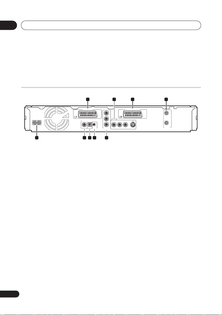
Rear panel connections
1 2
AV 1 (RGB) – TV AV 2 (INPUT 1/DECODER)
AC IN
5 6 7 8 9
DIGITAL
CONTROL
OUT
COAXIAL
IN
G-LINK
1 AV1(RGB)-TV AV connector
Audio/video output SCART-type AV
connector for connecting to a TV or other
equipment with a SCART connector. The
video output is switchable between video, Svideo and RGB. See page
AV1 Out
on
page 119 for how to set this up.
2 OUTPUT
Stereo analog audio, video and S-video
outputs for connection to a TV or AV
amplifier/receiver.
3 AV2(INPUT 1/DECODER) AV
connector
Audio/video input/output SCART-type AV
connector for connecting to a VCR, or other
equipment with a SCART connector. The
input accepts video, S-video and RGB. See
AV2/L1 In
on page 119 for how to set this up.
4 ANTENNA IN (RF IN)/OUT
Connect your TV antenna to the
IN (RF IN)
to the
jack. The signal is passed through
ANTENNA OUT
jack for connection to
ANTENNA
your TV.
3 4
COMPONENT
VIDEO OUT
Y
P
B
OUTPUT
L
R
P
R
AUDIO
VIDEO
S-VIDEO
IN
OUT
ANTENNA
5 AC IN – Power inlet
6 DIGITAL AUDIO OUT
Coaxial digital audio jack for connecting to
an AV amplifier/receiver, Dolby Digital/DTS/
MPEG decoder or other equipment with a
digital input.
7 CONTROL IN
Use to control this recorder from the remote
sensor of another Pioneer component with a
CONTROL OUT
Pioneer
OUT
of the other component to the
CONTROL IN
terminal and bearing the
mark. Connect the
of this recorder using a mini-
plug cord.
8 G-LINK™
Use to connect the supplied G-LINK™ cable
to enable GUIDE Plus+® to control an
external satellite receiver, etc.
9 COMPONENT VIDEO OUT
A high-quality video output for connecting to
a TV or monitor with a component video
input.
CONTROL
14
En
Page 15
Connecting up
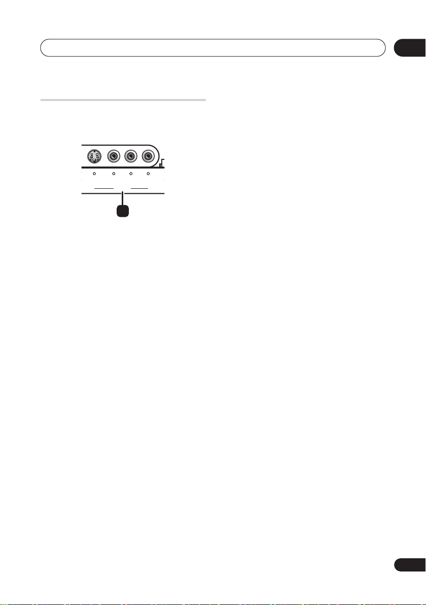
Front panel connections
On the front panel a flip-down cover hides
more connections.
02
S-VIDEO VIDEO L AUDIO R
INPUT 2
(MONO)
10
10 INPUT 2
Audio/video input (stereo analog audio;
composite and S-video video), especially
suitable for camcorders, game consoles,
portable audio, etc.
15
En
Page 16
02
Connecting up
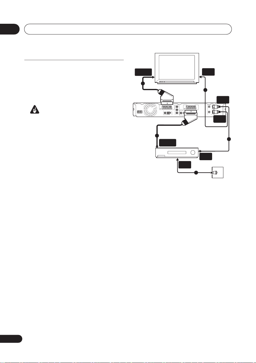
Easy connections
The setup described below is a basic setup
that allows you to watch and record TV
programs, and play discs. Other types of
connections are explained starting on the
following page.
Important
• These connections use SCART cables
(not supplied). If your TV (or VCR) does
not have a SCART connection, see the
following page for connecting up using
the supplied audio/video cable.
• The
AV1(RGB)-TV
AV connector can
output ordinary (composite), S-video or
RGB video, plus stereo analog audio. The
AV2(INPUT 1/DECODER)
connector
accepts ordinary, S-video and RGB video
input, as well as stereo analog audio.
See
AV1 Out
on page 119 and
AV2/L1 In
on page 119 for how to set them up.
• Before making or changing any rear
panel connections, make sure that all
components are switched off and
unplugged from the wall outlet.
SCART AV
CONNECTOR
4
AC IN
TV
AV 1 (RGB) – TV AV 2 (INPUT 1/DECODER)
DIGITAL
CONTROL
OUT
COAXIAL
IN
G-LINK
5
SCART AV
CONNECTOR
VCR
COMPONENT
VIDEO OUT
Y
P
B
OUTPUT
PR
AUDIO
ANTENNA
LR
IN
ANTENNA
IN
3
ANTENNA
IN (RF IN)
IN
OUT
VIDEO
ANTENNA
S-VIDEO
ANTENNA
OUT
2
ANTENNA
OUT
1
Antenna/cable TV
wall outlet
16
En
Page 17

Connecting up
02
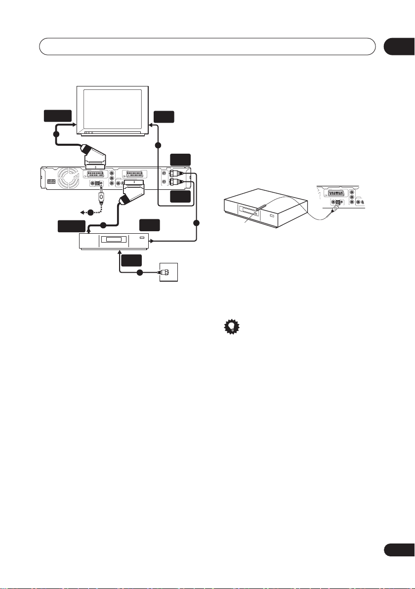
1 Connect the cable from the antenna/
cable TV outlet to the antenna input on
your VCR.
• If you are not connecting a VCR in the
chain, connect it to the
(RF IN)
jack on this recorder and skip the
ANTENNA IN
next step.
2 Use an RF antenna cable (one is
supplied) to connect the antenna output
of your VCR to the ANTENNA IN (RF IN) of
this recorder.
3 Use another RF antenna cable to
connect the ANTENNA OUT of this
recorder to the antenna input on your
TV.
4 Use a SCART cable (not supplied) to
connect the AV1(RGB)-TV AV connector
on this recorder to the SCART AV
connector on your TV.
5 Use another SCART cable to connect
the AV2(INPUT 1/DECODER) AV
connector to a SCART AV connector on
your VCR.
Tip
• This recorder has a ‘through’ function
which allows you to record a TV program
from the built-in TV tuner in this recorder
while watching a video playing on your
VCR. (To use this feature when the
recorder is in standby,
must be set to
Off
Power Save
—see
Power Save
on
page 116).
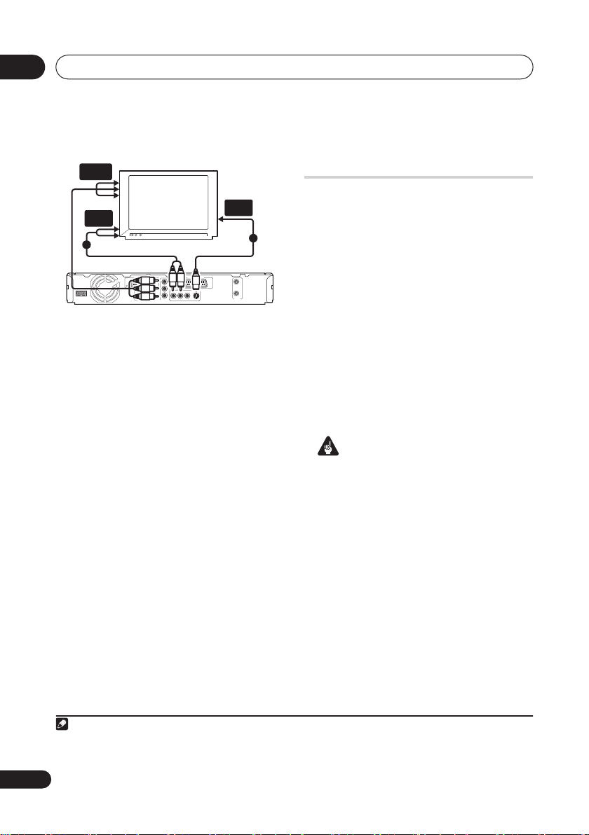
Using other types of audio/
video output
If you can’t use the SCART AV connector to
connect your TV to this recorder, there are
standard audio/video output jacks, as well as
an S-video and component video output.
Using the supplied audio/video
cable
AUDIO
INPUT
VIDEO
INPUT
TV
1
2
AV 1 (RGB) – TV AV 2 (INPUT 1/DECODER)
AC IN
Y
B
P
OUTPUT
DIGITAL
CONTROL
L
R
OUT
PR
COAXIAL IN
VIDEOAUDIO
COMPONENT
G-LINK
S-VIDEO
VIDEO OUT
1 Connect the VIDEO OUTPUT jack to a
video input on your TV.
Use the yellow jack of the supplied audio/
video cable for the video connection.
2 Connect the AUDIO OUTPUT jacks to
the corresponding audio inputs on your
TV.
Use the red and white jacks of the supplied
audio/video cable for the audio connection.
Make sure you match up the left and right
outputs with their corresponding inputs for
correct stereo sound.
IN
OUT
ANTENNA
17
En
Page 18
02
Connecting up
Using the S-video or component
video output
COMPONENT
VIDEO INPUT
S-VIDEO
S-VIDEO
on page 119
INPUT
1
IN
OUT
ANTENNA
S-VIDEO
AUDIO
INPUT
TV
2
AV 1 (RGB) – TV AV 2 (INPUT 1/DECODER)
AC IN
Y
P
B
OUTPUT
DIGITAL
CONTROL
L
R
OUT
PR
COAXIAL IN
VIDEOAUDIO
COMPONENT
G-LINK
VIDEO OUT
1 Connect the S-video or component
video output to a similar input on your
TV.
For an S-video connection, use an S-video
cable (not supplied) to connect the
OUTPUT
jack to an S-video input on your TV.
For a component video connection, use a
component video cable (not supplied) to
connect the
COMPONENT VIDEO OUT
jacks to a component video input on your TV.
See also
Component Video Out
for how to set up the component video
output for use with a progressive scancompatible TV.
2 Connect the AUDIO OUTPUT jacks to
the corresponding audio inputs on your
TV.
You can use the supplied audio/video cable,
leaving the yellow video plug disconnected.
Make sure you match up the left and right
outputs with their corresponding inputs for
correct stereo sound.
Connecting to a cable box,
satellite receiver or digital
terrestrial receiver
If you have a cable, satellite or digital
terrestrial receiver with a built-in decoder,
connect it to this recorder and your TV as
shown on the following page.
using a separate decoder box for your cable/
satellite TV, set up following the instructions
on the next page.
Using the setup on this page you can:
• Record any channel by selecting it on
the cable box, satellite receiver or digital
terrestrial receiver.
• Change channels and set timer
recordings on the external receiver using
the GUIDE Plus+® system (via the
G-LINK™ cable, and after setting up).
Important
• Do not connect this recorder to your TV
‘through’ your VCR, satellite receiver or
other component. Always connect each
component directly to your TV or AV
amplifier/receiver.
• When using the GUIDE Plus+ system to
make a timer recording from an external
receiver, make sure that the external
receiver is switched on.
1
If you are
Note
1 The diagram shows SCART video connections, but you can alternatively use any of the other audio/video con-
nections.
18
En
Page 19
Connecting up
DIGITAL
OUT
CONTROL
G-LINK
COAXIALIN
AUDIO
L
R
COMPONENT
VIDEO OUT
Y
P
B
PR
OUTPUT
AV 1 (RGB) – TV
SCART AV
CONNECTOR
2
TV
AV 1 (RGB) – TV AV 2 (INPUT 1/DECODER)
AC IN
Y
B
P
OUTPUT
DIGITAL
CONTROL
L
R
OUT
PR
COAXIAL IN
COMPONENT
G-LINK
VIDEO OUT
4
SCART AV
CONNECTOR
Cable/Satellite/
Digital Terrestrial
receiver
3
ANTENNA
1 Connect RF antenna cables as shown.
This enables you to watch and record TV
channels.
2 Use a SCART cable (not supplied) to
connect the AV1(RGB)-TV AV connector
to a SCART AV connector on your TV.
This enables you to watch discs.
3 Use another SCART cable to connect
the AV2(INPUT 1/DECODER) AV
connector to a SCART AV connector on
your cable box/satellite/digital terrestrial
receiver.
This enables you to record scrambled TV
channels.
ANTENNA
IN
1
ANTENNA
IN (RF IN)
IN
OUT
S-VIDEO
ANTENNA
OUT
ANTENNA
ANTENNA
OUT
VIDEOAUDIO
IN
1
Satellite dish/
antenna/cable TV
wall outlet
4 Plug the supplied G-LINK™ cable to
the G-LINK™ jack.
This enables you to control the tuner in the
external receiver using the GUIDE Plus+®
system.
Position the IR transmitter end of the GLINK™ cable so that the IR receiver on your
cable/satellite/digital terrestrial receiver will
pick up the control signals (see diagram).
1
G-LINK cable
See the manual that came with your cable/
satellite/digital terrestrial receiver if you’re
not sure where the IR receiver is on the front
panel. Alternatively, experiment with the
remote control, operating it from very close
range until you find the place where the
receiver responds.
Tip
• This recorder has a ‘through’ function
which allows you to record a TV program
from the built-in TV tuner in this recorder
while watching a video playing on your
VCR. (To use this feature when the
recorder is in standby,
must be set to
Off
Power Save
—see
Power Save
page 116).
02
on
19
En
Page 20
02
Connecting up
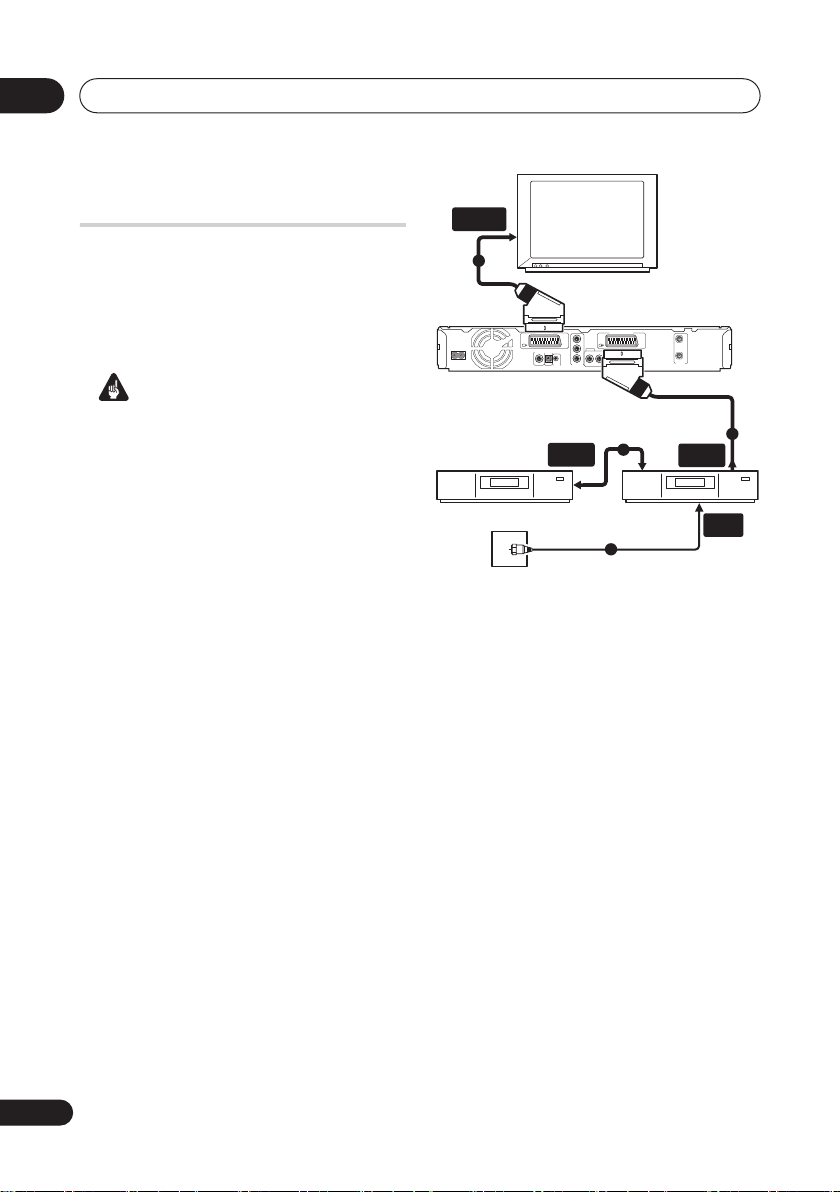
Connecting an external
decoder box (1)
If you have an external, dedicated decoder
box for your satellite or cable TV system, use
the setup described on this page. See the
previous page for how to connect the GLINK™ cable.
Important
• Do not connect your decoder box directly
to this recorder.
• Information from the decoder (for
example, relating to pay TV services), is
only viewable when this recorder is off
(in standby).
• For timer recording to work properly on
this recorder, the VCR/satellite receiver/
cable box must also be switched on
during recording.
• It is not possible to watch one TV
program and record another using this
setup.
SCART AV
CONNECTOR
4
TV
AV 1 (RGB) – TV AV 2 (INPUT 1/DECODER)
AC IN
Decoder
Antenna/cable TV
wall outlet
DIGITAL
OUT
COAXIAL IN
CONTROL
G-LINK
SCART AV
CONNECTOR
COMPONENT
VIDEO OUT
Y
B
P
OUTPUT
PR
LR
VIDEOAUDIO
S-VIDEO
2
VCR/Satellite receiver
/Cable box
1
IN
OUT
ANTENNA
SCART AV
CONNECTOR
ANTENNA
IN
3
1 Connect the cable from the antenna/
cable TV outlet to the antenna input on
your VCR/satellite receiver/cable box.
2 Use a SCART cable (not supplied) to
connect your decoder to your VCR/
satellite receiver/cable box.
See the manual for your decoder box for
more detailed instructions.
3 Use a SCART cable to connect your
VCR/satellite receiver/cable box to the
AV2(INPUT 1/DECODER) AV connector on
this recorder.
4 Use a SCART cable to connect the
AV1(RGB)-TV AV connector to your TV.
20
En
Page 21
Connecting up
02
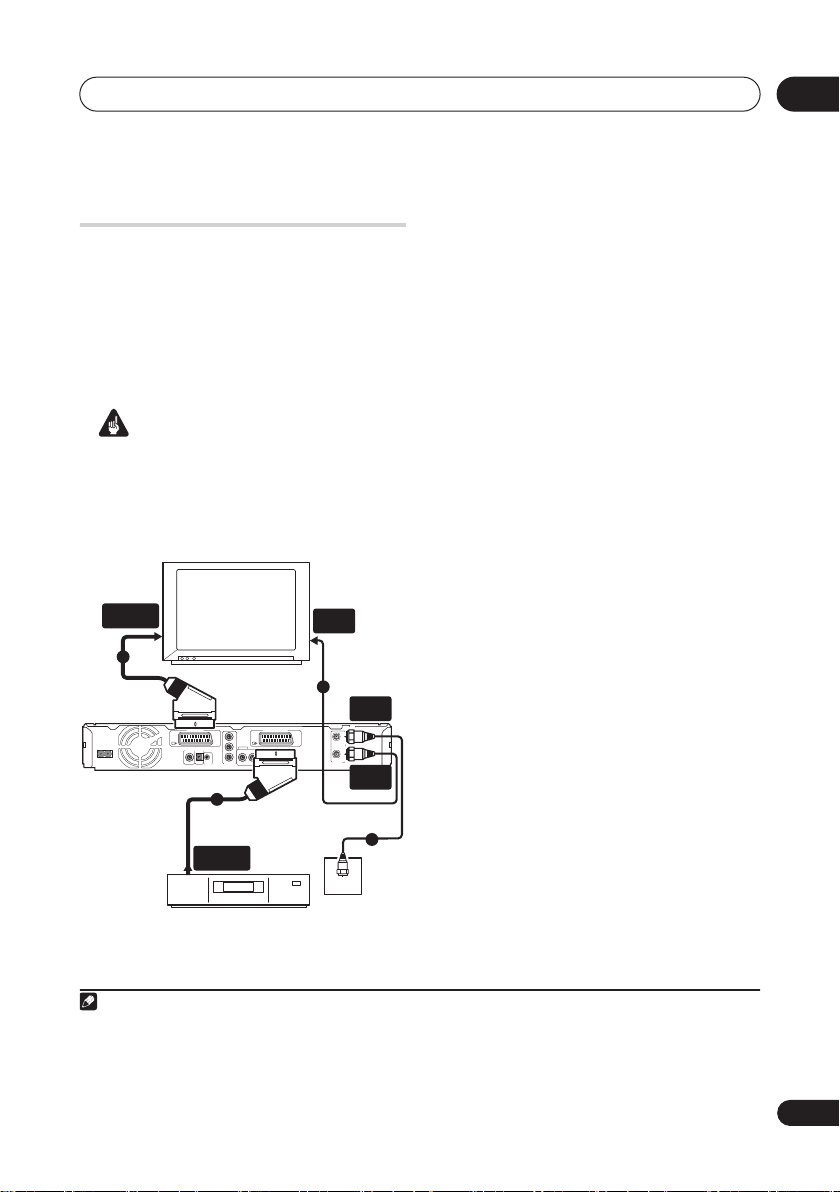
Connecting an external
decoder box (2)
If you only have a decoder, connect it to this
recorder and your TV as shown on this
1
page.
Using the setup on this page you can:
• Record scrambled channels received
using the recorder’s built-in TV tuner.
Important
• Do not connect this recorder ‘through’
your VCR, satellite receiver or cable box.
Always connect each component
directly to your TV or AV amplifier/
receiver.
AC IN
SCART AV
CONNECTOR
2
AV 1 (RGB) – TV AV 2 (INPUT 1/DECODER)
Y
P
B
OUTPUT
DIGITAL
CONTROL
OUT
COAXIAL
LR
PR
IN
COMPONENT
G-LINK
VIDEO OUT
3
ANTENNA
IN
TV
1
ANTENNA
IN (RF IN)
IN
OUT
VIDEOAUDIO
S-VIDEO
ANTENNA
ANTENNA
OUT
1 Connect RF antenna cables as shown.
This enables you to watch and record TV
channels.
2 Use a SCART cable (not supplied) to
connect the AV1(RGB)-TV AV connector
to a SCART AV connector on your TV.
This enables you to watch discs.
3 Use another SCART cable to connect
the AV2(INPUT 1/DECODER) AV
connector to a SCART AV connector on
your decoder box.
This enables you to record scrambled TV
channels.
Antenna/cable TV
wall outlet
1
SCART AV
CONNECTOR
Decoder
Note
1 In order to use this setup, you will need to make the following settings from the Initial Setup menu:
• Set the
AV2/L1 In
• From the
CH Setting
setting to
Manual CH Setting
on page 118).
Decoder
from the Initial Setup menu (see
screen, set the
Decoder
AV2/L1 In
on page 119).
setting for the scrambled channels to On (see
Manual
21
En
Page 22
02
Connecting up
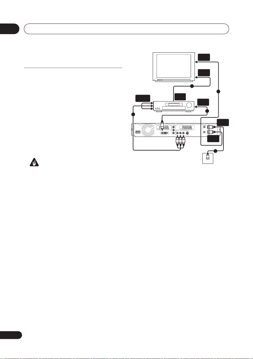
Connecting to an AV
amplifier/receiver
To enjoy multichannel surround sound you
need to connect this recorder to an AV
amplifier/receiver using the digital coaxial
output.
In addition to a digital connection, we
recommend also connecting using the
stereo analog connection for compatibility
with all discs and sources.
You’ll probably also want to connect a video
output to your AV amplifier/receiver. Use the
ordinary video output (as shown here), or the
S-video output.
Important
• Noise may be output from your speakers
if the recorder is not set up to work with
your AV amplifier/receiver properly (see
Audio Out
• Do not connect this recorder to your TV
‘through’ your VCR using A/V cables.
Always connect it directly to your TV.
on page 120).
ANTENNA
IN
VIDEO
IN
AUDIO/VIDEO
3
AC IN
TV
IN
AV amp/
receiver
AV 1 (RGB) – TV AV 2 (INPUT 1/DECODER)
DIGITAL
CONTROL
OUT
COAXIAL
IN
COMPONENT
G-LINK
VIDEO OUT
4
VIDEO
OUT
Y
B
P
OUTPUT
LR
PR
AUDIO
DIGITAL
VIDEO
S-VIDEO
IN
2
IN
OUT
ANTENNA
ANTENNA
OUT
Antenna/cable TV
wall outlet
1
1
ANTENNA
IN (RF IN)
1 Connect RF antenna cables as shown.
This enables you to watch and record TV
channels.
2 Connect one of the DIGITAL OUT
COAXIAL jack on this recorder to an
coaxial digital input on your AV
amplifier/receiver.
This enables you to listen to multichannel
surround sound.
3 Connect the analog AUDIO OUTPUT
and VIDEO OUTPUT jacks on this recorder
to an analog audio and video input on
your AV amplifier/receiver.
4 Connect the AV amplifier/receiver’s
video output to a video input on your TV.
22
En
Page 23
Connecting up
02
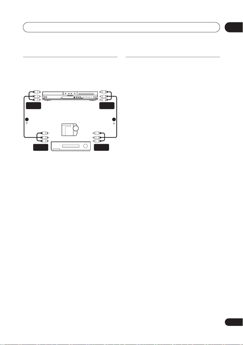
Connecting other AV sources
Connecting a VCR or analog
camcorder
HDD/DVD
STANDBY/ON
AUDIO/VIDEO
OUTPUT
(Rear panel) (Front panel)
1 2
AUDIO/VIDEO
INPUT
OPEN/CLOSE
Analog camcorder
VCR
1 Connect a set of audio and video
inputs of your VCR or camcorder to a set
of outputs on this recorder.
This enables you to record from this recorder
to your VCR or camcorder.
• You can use standard video or S-video
cables for the video connection.
• Alternatively, you can use the
AV2(INPUT 1/DECODER)
connector for audio/video input and
output with just one SCART cable.
2 Connect a set of audio and video
outputs of your VCR or camcorder to a
set of inputs on this recorder.
This enables you to record tapes from your
VCR or camcorder.
• You can use standard video or S-video
cables for the video connection.
• The front panel connections make
convenient connections for a camcorder
input.
ONE
STOP
TOUCH
CH
+–
REC
COPY
SCART
REC
AUDIO/VIDEO
AUDIO/VIDEO
OUTPUT
INPUT
Plugging in
After checking all the connections, plug in
the recorder.
1 Use the supplied power cable to
connect this recorder to a power outlet.
23
En
Page 24
03
Controls and displays
Chapter 3
Controls and displays
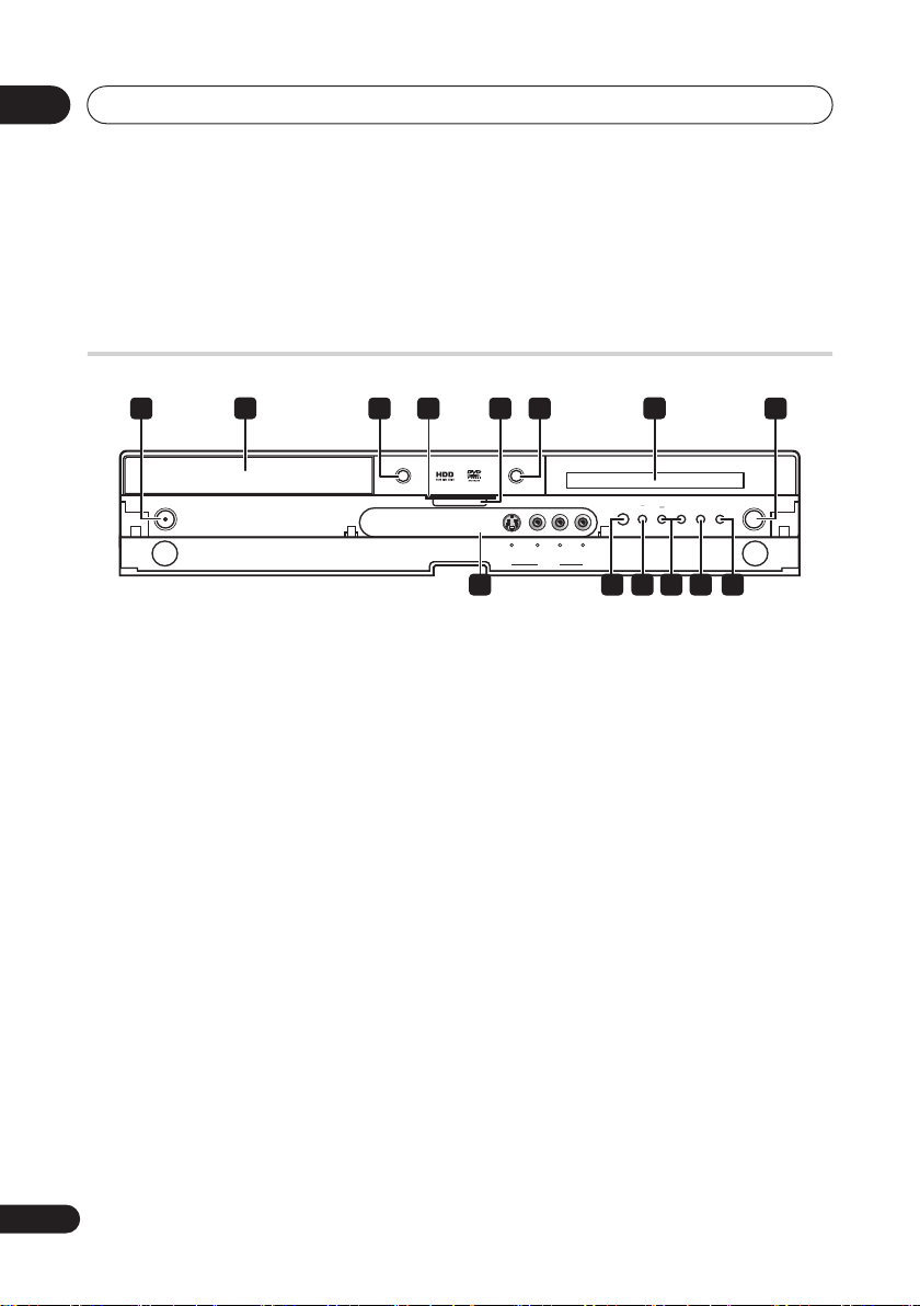
Front panel
1 83 4 65
OPEN/CLOSE
STANDBY/ON
DVR-540H-S
1 STANDBY/ON
Press to switch the recorder on/into standby.
2 Disc tray
OPEN/CLOSE
3
Press to open/close the disc tray.
4 HDD / DVD indicators
Indicator lights blue when the hard disk
(HDD) is selected; orange when the DVD
drive is selected.
5 PAUSE LIVE TV
(page 58)
Press to start recording the current TV
channel, but with playback paused,
effectively pausing the broadcast.
6 HDD/DVD
Press to switch between HDD and DVD for
recording and playback.
7 Front panel display and IR remote
sensor
See
Display
on page 25 for details.
72
HDD/DVD
S-VIDEO VIDEO L AUDIO R
(MONO)
INPUT 2
10
119
REC
COPY
1312 14
ONE
STOP
TOUCH
CH
+–
REC
8 REC
Press to start recording. Press repeatedly to
set the recording time in 30 minute blocks.
9 Front panel inputs
See
Front panel connections
on page 15 for
more information on these.
10
Press to start or restart playback.
11
Press to stop playback.
12 CH +/–
Use to change channels, skip chapters/
tracks, etc.
13 ONE TOUCH COPY
(page 95)
Press to start One Touch Copy of the
currently playing title to DVD or the HDD.
14 STOP REC
Press to stop recording.
24
En
Page 25
Controls and displays
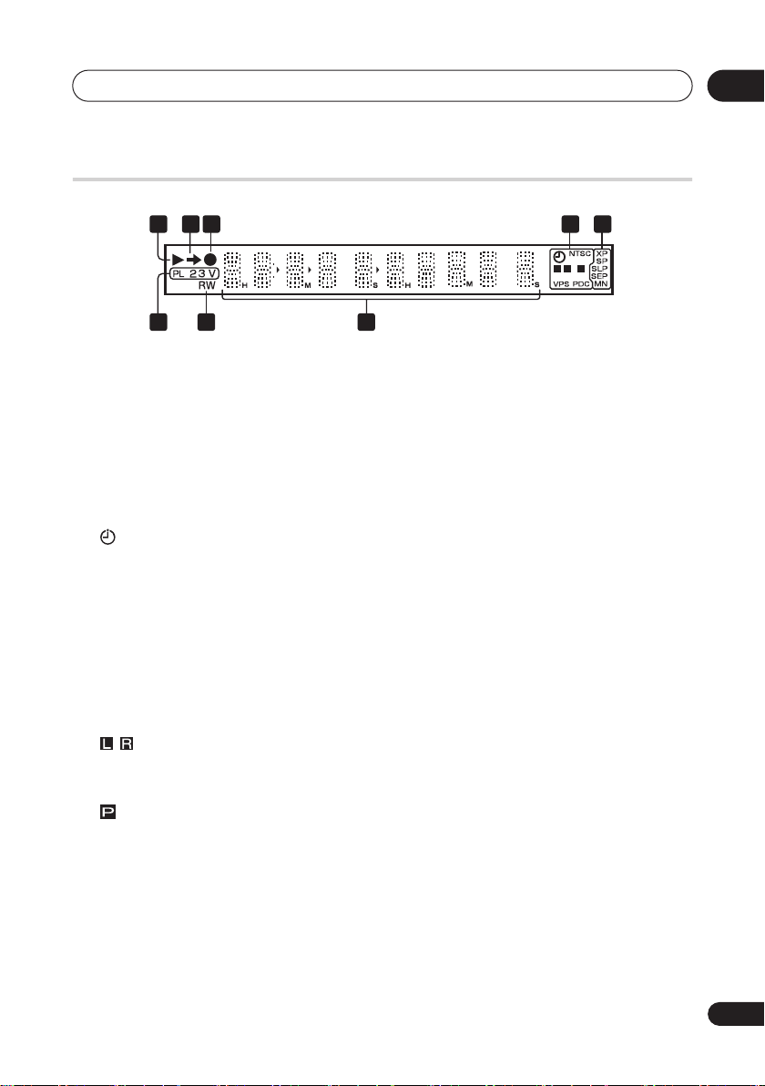
Display
2 43 5
1
03
L
P
R
8 7
1
Lights during playback; blinks when
playback is paused.
2
Lights when copying.
3
Lights during recording; blinks when
recording is paused.
4
(page 59)
Lights when a timer recording has been
set. (Indicator blinks if the timer has
been set to DVD but there isn’t a
recordable disc loaded, or the timer has
been set to HDD but the HDD is not
recordable.)
NTSC
Lights when the video output signal
format is NTSC.
(page 120)
Indicates which channels of a bilingual
broadcast are recorded.
(page 119)
Lights when the component video output
is set to progressive scan.
VPS / PDC
(page 59)
Lights when receiving a VPS/PDC
broadcast during a VPS/PDC-enabled
timer recording.
6
5 Recording quality indicators
XP
Lights when the recording mode is set to
XP
(best quality).
SP
Lights when the recording mode is set to
SP
(standard play).
LP / SLP
Lights when the recording mode is set to
LP
(long play) or
SLP
(super-long play).
EP / SEP
Lights when the recording mode is set to
EP
(extended play) or
SEP
(super-
extended play).
MN
Lights when the recording mode is set to
MN
(manual recording level) mode.
6 Character display
7R / RW
Lights when a recordable DVD-R or DVD-RW
disc is loaded.
8 PL
(page 82)
Lights when a VR mode disc is loaded
and the recorder is in Play List mode.
2 3
(page 126)
Shows the remote control mode (if
nothing is displayed, the remote control
mode is 1).
(page 56)
25
En
Page 26
03
Controls and displays
V
Lights when an unfinalized Video mode
disc is loaded.
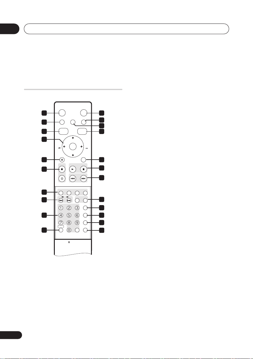
Remote control
STANDBY/ON
1 11
2
TOP MENU
DISC
NAVIGATOR
3 14
4
CM
BACK
PAUSE RETURN
5 15
6
STOP REC
TIMER REC
7
8
REC MODE
AUDIO
9
SHIFT CLEAR
10
HOME MENU INFOPAUSE LIVE TV
CHANNEL
ENTER
CHANNEL
PREV NEXT
//
SUBTITLE
HDD/DVD
GUIDE
+
–
PLAYREC STOP
HELP
ONE TOUCH COPY
ANGLE
PLAY MODE
OPEN
OPEN
CM
SKIP
TV/DVD
INPUT SELECT
MENU
DISPLAY
1 STANDBY/ON
Press to switch the recorder on/into standby.
2 PAUSE LIVE TV
(page 58)
Press to start recording the current TV
channel, but with playback paused,
effectively pausing the broadcast.
3 DISC NAVIGATOR
MENU
(page 68)
(page 72, 81)
/ TOP
Press to display the Disc Navigator screen,
or the top menu if a DVD-Video or finalized
12
13
DVD-R/RW (Video) disc is loaded.
4
///
and ENTER
Used to navigate all on-screen displays.
Press
ENTER
to select the currently
highlighted option.
CM BACK (commercial back)
16
17
Press repeatedly to skip progressively
backward through the audio or video
playing.
CM SKIP (commercial skip)
Press repeatedly to skip progressively
18
19
20
21
22
forward through the audio or video
playing.
CHANNEL +/–
(page 55)
Press to change the channel of the builtin TV tuner.
5 PAUSE
Press to pause playback or recording.
6 Recording controls
REC
(page 57)
Press to start recording. Press
repeatedly to set the recording time in
blocks of 30 mins.
When the red action button is visible in a
GUIDE Plus+® screen, use for OneButton-Record.
STOP REC
Press to stop recording.
26
En
Page 27

Controls and displays
03
7 GUIDE Plus+® Action buttons
When in the GUIDE Plus+® system,
these buttons act as the Red, Green,
Yellow and Blue Action buttons (the
functions of these buttons change
according to the GUIDE Plus+® Area.
(page 37)
TIMER REC (page 37)
Hold SHIFT and press to set a timer
recording from the GUIDE Plus+®
system.
8 (page 73)
Press to start reverse or forward
scanning. Press again to change the
speed.
/ / (page 74)
While paused, press and hold to start
slow-motion playback. Press repeatedly
to change the playback speed.
While paused, press to advance a single
frame in either direction.
When GUIDE Plus+® is displayed, use
to display the previous/next day.
9 Number buttons, CLEAR
Use the number buttons for track/
chapter/title selection; channel
selection, and so on. The same buttons
can also be used to enter names for
titles, discs and so on.
Use CLEAR to clear an entry and start
again.
REC MODE (page 56)
Hold SHIFT and press repeatedly to
change the recording mode (picture
quality).
AUDIO (page 55, 78)
Hold SHIFT and press to change the
audio language or channel. (When the
recorder is stopped, press to change the
tuner audio.)
SUBTITLE (page 77)
Hold SHIFT and press to display/change
the subtitles included in multilingual
DVD-Video discs.
ANGLE (page 79)
Hold SHIFT and press to switch camera
angles on discs with multi-angle scenes.
PLAY MODE (page 74)
Hold SHIFT and press to change the play
mode (search, repeat, program play,
etc.)
10 SHIFT
Use to access functions on the remote
printed in green.
11 HDD/DVD (page 57)
Press to select the hard disk (HDD) or DVD
for recording and playback.
12 INFO
Press to see additional information for the
highlighted item in GUIDE Plus+®.
13 HOME MENU
Press to display the Home Menu, from
which you can navigate all the functions of
the recorder.
14 GUIDE
Press to display the GUIDE Plus+® screen;
press again to exit.
15 RETURN
Press to go back one level in the on-screen
menu or display.
16 PLAY (page 67)
Press to start playback.
STOP (page 67)
Press to stop playback.
27
En
Page 28

03
Controls and displays
17
Press to skip to the previous or next title/
chapter/track/folder; or to display the
previous or next menu page.
When GUIDE Plus+® is displayed, use to
display the previous/next page.
18 HELP
Press for help on how to use the current
GUI screen.
TV/DVD
Press to switch between ‘TV mode’, in
which you get the picture and sound
from the TV’s tuner, and ‘DVD mode’, in
which you get picture and sound from
the recorder’s tuner (or an external
input).
19 ONE TOUCH COPY
Press to start One Touch Copy of the
currently playing title to DVD or the HDD.
20 INPUT SELECT
Press to change the input to use for
recording.
21 MENU
Press to display the disc menu if a DVDVideo, finalized DVD-R/-RW or finalized
DVD+R/+RW disc is loaded.
When in the GUIDE Plus+® system, use to
jump directly to the Menu bar.
22 DISPLAY
(page 68)
(page 79)
Displays/changes the on-screen
information displays.
(page 95)
(page 63)
28
En
Page 29
Getting started
Chapter 4
Getting started
04
Switching on and setting up
When you switch the recorder on for the first
time, you can make several basic settings
using the Setup Navigator feature. This takes
you through setting the clock, the internal TV
tuner and the video output.
If you’re using the recorder for the first time,
we strongly recommend you use the Setup
Navigator before starting to use the
recorder.
1 Switch on your TV and set the video
input to this recorder.
STANDBY/ON
2 Switch on the recorder.
When you switch on for the first time, your
TV should display the Setup Navigator
screen (If the Setup Navigator doesn’t
appear, you can also access it from the
Initial Setup menu; see page 116).
• If this recorder is connected to a
compatible TV using a fully-wired 21-pin
SCART cable, the recorder will take a few
seconds to download country, TV screen
size and language information. (Check
the manual that came with your TV for
compatibility information.)
ENTER
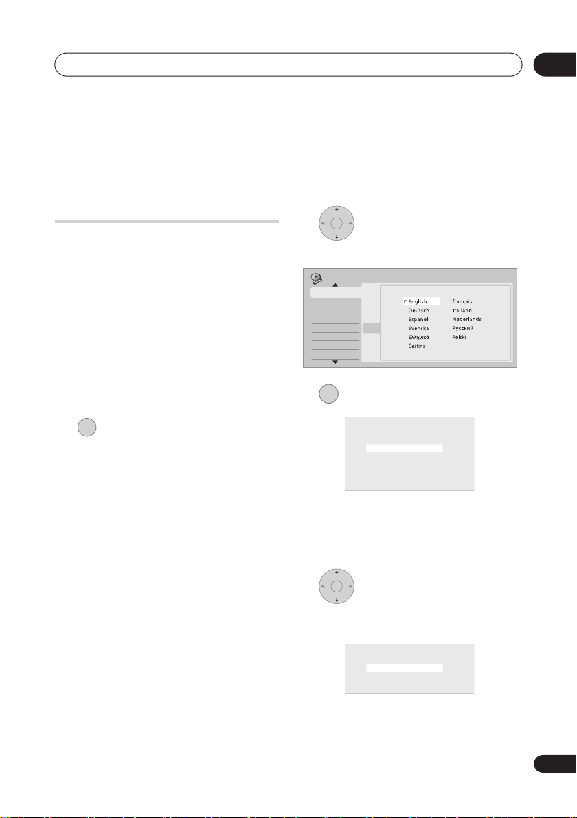
3 Choose a language (then
press ENTER).
Initial Setup
Basic
Basic
Tuner
Video In/O ut
Audio In
Audio O ut
Language
Reco rding
Playback
ENTER
4 Start the Setup Navigator.
Language
Clock Setting
Input Line System
Pow er Save
Help
Setup N avigator
Setup N avigator
Setting
Complete this setup before you
Line System
start using your recorder.
r Save
Start
Start
Cancel
Navigator
Navigator
Please use the Initial Setup if you
want to make more detailed settings.
• If you don’t want to use the Setup
Navigator, press
then press
to select
ENTER
to exit the Setup
Cancel
,
Navigator.
ENTER
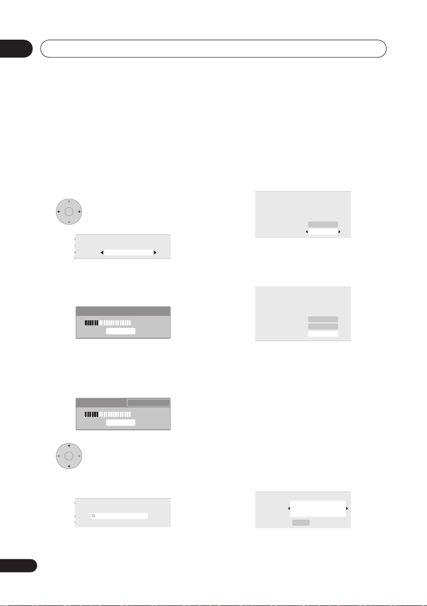
5 Select the Auto Channel
Setting (‘Auto Scan’ or ‘Download from
TV’), or ‘Do not set’.
Setting
Auto Channel Setting
Line System
r Save
English
Auto Scan
Download from TV
Navigator
Do not Set
Navigator
29
En
Page 30
04
Getting started
• Select
Do not set
if you want to skip
channel setup (because they have
already been set up, for example).
• You can only use the
TV
feature if this recorder is connected
Download from
to your TV using a fully-wired 21-pin
SCART cable via the
AV1(RGB)-TV
connector, and if your TV supports this
function (check your TV’s instruction
manual for more details).
ENTER
• Select your country.
Setting
Setting
Country Selection
Line System
Line System
r Save
r Save
Country
UK
• Auto-tuning channels
The
Auto Scan
option automatically scans
and sets the channel presets.
Tun ing
32/99
Cancel
• Downloading channels from your TV
Use the
Download from TV
option to
download all the channels that your TV is
tuned to.
Downloading Pr 5
32/99
Cancel
ENTER
6 Select ‘Auto’ for automatic
time setting, or ‘Manual’ to set the clock
manually.
Setting
Clock Setting
Line System
Auto
r Save
Auto
Manual
• Auto clock setting
Some TV channels broadcast time
signals together with the program. This
recorder can use these signals to set the
clock automatically.
Set ‘Clock Set CH‘ to the channel
preset number that broadcasts a time
signal, then move the cursor down to
‘Start’ and press ENTER.
Setting
Auto Clock Setting
Line System
Date
r Save
Time
Navigator
Navigator
Clock Set CH
–– / –– / ––––
–– : ––
Pr 1
Start
The recorder takes a short while to set
the time. After you see that it’s set, select
Next
to proceed.
Setting
Auto Clock Setting
Line System
Date
Time
Clock Set CH
SUN 01 / 01 / 2006
11 : 20
Pr 1
Start
Next
r Save
Navigator
Navigator
If the time could not be set
automatically, press
RETURN
to go back
to the previous screen and select
Manual
.
• Manual clock setting
If no stations in your area are
broadcasting time signals, you can set
the clock manually.
Use the
/
buttons to set your
time zone.
You can set this by selecting a city or a
time relative to GMT.
Setting
Manual Clock Setting
Line System
Time Zone
r Save
Navigator
Summer Time
Navigator
Off
England
London
1/2
30
En
Page 31

Getting started
Setting
04
Press then use the
/
buttons to
select ‘On’ or ‘Off’ for summer time,
then press ENTER.
Select On if you are currently using
summer time.
Setting
Manual Clock Setting
Line System
Time Zone
r Save
Navigator
Summer Time
Navigator
On
England
London
1/2
Set the date (day/month/year) and
time, then press ENTER to make all
the settings.
Setting
Line System
r Save
Navigator
Navigator
Use the
Manual Clock Setting
Date
Time
Time Zone
Summer Time
/
01 / /01
00 : 00
England
London
On
buttons to change the
2/2
2006SUN
value in the highlighted field.
Use the
/
buttons to move from one
field to another.
• You can go back to the previous screen
at anytime in the Setup Navigator by
pressing
ENTER
RETURN
.
7 Select the TV screen type,
‘Wide (16:9)’ or ‘Standard (4:3)’.
Setting
TV Screen Size
Line System
r Save
Wide (16:9)
Standard (4:3)
ENTER
8 Select whether or not your TV
is compatible with progressive scan
video.
Setting
Progressive
Line System
r Save
Compatible
Not Compatible
Not Compatible
Navigator
Don't Know
Navigator
• Note that progressive scan video is only
output through the
AV1(RGB)-TV
connector and the component video
outputs.
ENTER
9 Press to continue after reading
the HDD caution.
Setting
In the event of HDD failure, recordings may
be lost or normal playback/recording may
Line System
not be possible.
r Save
As recordings might be lost in case of a HDD
failure, we recommend to use the HDD only
as temporary storage media.
Navigator
Navigator
Please copy recordings you want to keep
to recordable DVD.
Press ENTER to continue.
ENTER
10 Select ‘Finish Setup’ to exit
the Setup Navigator, or ‘Go Back’ if you
want to start again.
Setup is complete!
Line System
Enjoy using your DVD recorder!
r Save
Finish Setup
Finish Setup
Navigator
Go Back
Navigator
That completes basic setup using the Setup
Navigator.
• If there are blank channels with no
station, you can set these to skip using
the manual channel setting. See
CH Setting
on page 118.
Manual
31
En
Page 32

04
Getting started
Setting up the GUIDE Plus+®
system
The GUIDE Plus+® system is a free,
interactive on-screen television
programming guide. The system offers
program listings for all major channels, onetouch recording, search by genre,
recommendations according to your profile
and more.
For the GUIDE Plus+ system to function
correctly, it is important that you set the
language and country correctly in the Setup
Navigator, and that you have performed a
scan for available channels, as these are all
used by the GUIDE Plus+ system. If any of
these things are not yet set, please run the
Setup Navigator first (see
setting up
on page 29).
TV listings information is received via ‘host
channels’. In order to receive the correct TV
listings information for your country or
region you need to set up the GUIDE Plus+
system and ‘download’ the TV listings
information. The initial download can take
up to 24 hours, but once this is done, all
future updates are automatic.
Switching on and
The language and country settings are
already set to whatever you selected in the
Setup Navigator.
ENTER
2 Highlight ‘Postal Code’.
REC MODE
AUDIO SUBTITLE
ANGLE
PLAY MODE
ENTER
3 Enter your postal
code.
GUIDE
1 Display the GUIDE Plus+ setup
menu.
32
En
The system uses your postal code to identify
which TV listings data is correct for the area
in which you live, so it is important that you
enter it correctly.
Page 33

Getting started
04
4 If you are using an external receiver
(such as a satellite receiver) with the
supplied G-LINK cable, complete this
step, otherwise jump to step 5 below.
• See
Connecting to a cable box, satellite
receiver or digital terrestrial receiver
page 18 for more on using the supplied
G-LINK cable.
• Select
After pressing
• Select your reception method
• Select your provider (if applicable).
• Select the brand of your external
• Identify which input your external
After completing these steps the recorder
will try and communicate with your external
receiver and change the channel via the GLINK cable. If the channel was successfully
changed, select
External Receiver 1, 2
press
ENTER
external receiver, use
1
. You can add further receivers in 2 and
3
if you need to.)
(
Terrestrial, Cable
receiver.
receiver is connected to.
. (If you have just one
External Receiver
ENTER
:
or
Satellite
Yes
to confirm.
on
or 3, then
).
No
If the channel did not change, select
GUIDE Plus+ system will try other codes
assigned to your external receiver. If none of
the codes changes the channel
successfully, tune your external receiver to
the host channel for your country (refer to
step
5
below) and leave it on overnight. The
recorder needs to be in standby; it will wake
up automatically and download new codes
from the host channel. The next day, try this
setup process again:
• Press
• Press
• Continue setting up from the start of this
If your external receiver still doesn’t respond
to the G-LINK controller, please call
customer support and report the brand and
model of your external receiver.
See also
troubleshooting
5 Identify the host channel for your
country.
The TV listings information available in the
GUIDE Plus+ system is distributed
throughout Europe by selected broadcasters
called
host channel for your country is correctly
identified in order to receive listings
information (EPG download).
Follow
setup:
• Leave the recorder in standby overnight
GUIDE
Plus+ setup menu.
use
select Setup.
step again.
host channels
A, B
A
If you
receiver, this recorder will automatically
scan all channels for the host channel:
(do
not
to display the GUIDE
to highlight the Menu bar, then
to reach the Setup area and
GUIDE Plus+ FAQ and
on page 49.
. It is important that the
or C below depending on your
are not
using an external
leave it switched on).
. The
33
En
Page 34

04
Getting started
B
If you
are
using an external receiver,
you need to identify the host channel
from the table below:
Country/
Region
Austria Eurosport
Belgium RTL-TVI
France Canal+ Analog only
Germany Eurosport
Italy Sport Italia Analog only
Netherlands Music
Spain Tele 5 Analog only
Switzerland Eurosport
UK ITV, Eurosport ITV is analog only. Use
Host
channels
Music
Factory (TMF)
Factory
(TMF),
Eurosport
Comments
TMF will be switched
off in the near future.
TMF will be switched
off in the near future.
Eurosport if you are a
SKY subscriber and
you no longer have a
terrestrial antenna.
• Tune your external receiver to the
appropriate host channel and leave the
receiver on and the recorder in standby
overnight.
C
If you use
both
an external receiver
and this recorder as sources, follow the
instructions above for setting up without
an external receiver. Only if this is
unsuccessful try the external receiver
method.
About EPG download
• EPG data can only be received when the
recorder is in standby. (When not using
the recorder, therefore, please switch it
into standby.) If you’re using an external
receiver, leave this on when EPG data is
downloading.
• If you cannot receive any of the host
channels (see the above table) then you
won’t be able to use the GUIDE Plus+
system. In this case do not set the postal
code (or set Country to
GUIDE Plus+ setup screen. (When
GUIDE Plus+ service starts in your area,
set the postal code again.)
• Even if you can’t use the EPG functions
where you live, you can still set VIDEO
Plus+ timer recordings and manual
recordings — see
recording
on page 59.
• The front panel display shows
receiving data. If you power on the
recorder during an EPG download, the
download is canceled.
• EPG data may be received several times
a day. All updates are automatic.
• When downloading EPG data, the
recorder may sound as though it is on.
This is normal.
Other
) in the
Setting a timer
EPG
when
34
En
Page 35

Getting started
04
Checking the downloaded data the
following day
GUIDE
1 Display the GUIDE Plus+ screen.
You should see a grid filled with channel
logos and TV listings information. Use the
/
buttons to review the list. If you notice
that there are channels missing, or that
there are channels in the list that you don’t
get, go to the Editor screen:
• Press
• Press
• For any channel that you turn
repeatedly until the Menu bar is
highlighted.
until
Editor
is highlighted. The
main area of the screen now shows a list
of channels. Those that are turned
ON
are displayed in the grid; those that are
OFF
are hidden. Use the
///
buttons to move down the list and turn
channels
ON
or
OFF
as necessary.
ON
, the
GUIDE Plus+ system will need to know
how it is received (the source) and on
which program number. The source may
be the built-in tuner of this recorder, or
an external receiver. The program
number is the number on which the
channel can be found on its receiving
device/source. The entry in the Editor
screen must match this number for
correct recording of that channel.
• The above is especially important for the
‘host channel’. Please make sure that
the host channel is always switched
REC MODE
AUDIO SUBTITLE
ANGLE
PLAY MODE
ON
2 Change the program
numbers as you like.
Changing the program numbers allows you
to decide the order in which the channels
change when stepping through them
sequentially. You can do this to group
certain channels together, for example.
3 When you’re done, press the BLUE
Action button (Home) to get back to the
GUIDE Plus+ home screen.
• You can find detailed information on
using the GUIDE Plus+ system in the
following chapter.
.
35
En
Page 36

05
Using the GUIDE Plus+® electronic program guide
Chapter 5
Using the GUIDE Plus+®
electronic program guide
The GUIDE Plus+ system
The GUIDE Plus+® system* is a free,
interactive on-screen television
programming guide.
program listings for all major channels, onetouch recording, searching by genre,
recommendations according to your profile
and more. The GUIDE Plus+ system is a
convenient way to find out what's on right
now or during the coming week, by channel
or by genre. The GUIDE Plus+ system also
allows you to automatically set your viewing
and recording selections quickly and easily.
In order to receive the correct TV listings
information for your country or region you
need to set up the GUIDE Plus+ system and
‘download’ the TV listings information. If you
haven’t already done this, please turn to
Setting up the GUIDE Plus+® system on
page 32 before proceeding.
* GUIDE Plus+, S
G-LINK are (1) registered trademarks or
trademarks of, (2) manufactured under
license from and (3) subject of various
international patents and patent applications
owned by, or licensed to, Gemstar-TV Guide
International, Inc. and/or its related affiliates.
1
The system provides
HOWVIEW, VIDEO Plus+,
Legal Notice
GEMSTAR-TV GUIDE INTERNATIONAL, INC. AND/
OR ITS RELATED AFFILIATES ARE NOT IN ANY WAY
LIABLE FOR THE ACCURACY OF THE PROGRAM
SCHEDULE INFORMATION PROVIDED BY THE
GUIDE PLUS+ SYSTEM. IN NO EVENT SHALL
GEMSTAR-TV GUIDE INTERNATIONAL, INC. AND/
OR ITS RELATED AFFILIATES BE LIABLE FOR ANY
AMOUNTS REPRESENTING LOSS OF PROFITS, LOSS
OF BUSINESS, OR INDIRECT, SPECIAL, OR
CONSEQUENTIAL DAMAGES IN CONNECTION
WITH THE PROVISION OR USE OF ANY
INFORMATION, EQUIPMENT, OR SERVICES
RELATING TO THE GUIDE PLUS+ SYSTEM.
Note
1 The GUIDE Plus+ system can’t be used when the Input Line System is set to 525 System (see also Input Line
System on page 116).
36
En
Page 37

Using the GUIDE Plus+® electronic program guide
05
Using the GUIDE Plus+
system
All the various features and areas are colourcoded for ease of navigation. All screens
(with the exception of some setup screens)
have the following common elements:
1
2
1 Video window
watching the current program while
using the GUIDE Plus+ system.
2 Information panels
promotions or instructions on the GUIDE
Plus+ system.
3 Action bar
buttons change function depending on
the area.
4 Information box
program descriptions or help menus.
5 Menu bar
areas of the GUIDE Plus+ system.
6 Grid
– Shows TV listings information for
the next seven days by channel and time.
– Allows you to continue
– Display program
– colour-coded Action
– Shows short
– Gives access to the various
GUIDE Plus+ navigation
The table below shows a summary of the
remote buttons you’ll use to navigate the
GUIDE Plus+ system.
Key
GUIDE
3
4
5
///
RED, GREEN
6
YELLOW, BLUE
MENU
TIMER REC
(SHIFT + RED)
INFO
ENTER
Number
buttons
/
REC
/
What it does
Press to set or cancel One
Button Recording.
Press to display the GUIDE
Plus+ screen (also use to
exit).
Use to navigate screens
(highlight an item).
,
Action buttons that change
functionality depending on
the Area.
Press to jump directly to the
Menu bar.
Press to go directly to the
Schedule area.
Press to display extended
information for the current
program.
Press to confirm a selection
or to leave the GUIDE
Plus+ screen.
Use for numeric entry.
Press to select the previous/
next page of information (in
the grid, for example).
Press to select the previous/
next day.
37
En
Page 38

05
Using the GUIDE Plus+® electronic program guide
One-Button-Record
The
RED
anytime you can highlight a program title,
including from the Grid, after a search, or in
your recommendations in the My TV area.
The program name, date, channel, recording
start and end times are all set automatically
when you set a timer recording using OneButton-Record.
If you need to, you can edit the settings at
any time before the recording is due to start
(see
page 43).
1 Highlight a program title.
Action button (Record) is visible
Editing a scheduled recording
on
Lock / Unlock video window
When you enter the GUIDE Plus+ system,
the channel you were watching remains
visible in the video window. The date stamp
above the window lets you know the
channel, date and time.
The default setting for this window is
‘locked’, as indicated by a closed padlock
icon above the video window. When locked,
the video window always shows the channel
you were previously watching as you move
up and down through the listings grid.
If you prefer, you can unlock the video
window so that as you highlight different
channels in the listings grid, that channel is
shown in the video window.
1 Highlight a channel logo.
Channel logos are displayed to the left of
2 Press the RED Action button (Record).
The program is now set for recording. When
the program is due to start, the recorder will
switch to the correct channel and start
recording
• You can also use the
• You can review the shows you have set to
1 Recording times set using the GUIDE Plus+ system do not automatically change to reflect any changes that
may occur in the program broadcast schedules.
1
.
REC
the recording.
record in the Schedule Area (see also
The Schedule Area
Note
on page 43).
button to set
program titles.
2 Press the RED Action button (Unlock).
The padlock icon above the video window
becomes unlocked. It remains unlocked for
the remainder of your current TV viewing
session.
If you want to lock the video window again,
follow the same procedure. The
button will now act as Lock.
38
En
RED
Action
Page 39

Using the GUIDE Plus+® electronic program guide
05
Channel mosaic screen
You can switch the display style of channels
in the Grid Area, Schedule Area or My TV
Area from a list to a mosaic of channel icons
by pressing the
Select the channel icon you want using the
cursor buttons, then press
to the previous screen on that channel.
YELLOW
Action button.
ENTER
to return
Areas
The GUIDE Plus+® system consists of
seven
Areas
the Menu bar.
•
•
•
•
•
•
•
. All Areas can be accessed from
Grid
– The GUIDE Plus+ system Home
Area. Displays TV listings information for
the next seven days by time and channel.
Search
– Search for TV programs by
category (e.g., Sport), subcategory (e.g.,
Football) or keyword.
My TV
– Set up a profile and receive
recommendations according to your
preferences.
Schedule
recordings.
Info
such as weather (not available in all
regions).
Editor
Setup
system.
– Show all scheduled
– Area for additional information,
– Change channel settings.
– Setup the GUIDE Plus+®
The Grid Area
The Grid is the main TV listings screen of the
GUIDE Plus+ system and is the first screen
that you see when you press
see TV listings for the next seven days,
starting with the current day.
When you highlight a program in the Grid,
you can see information about it in the
Information Box, including title, synopsis,
channel, source, time and length. If there is
an
i
symbol in the Information Box, it means
that there is an extended synopsis available.
Press the
In some countries, you can also see a rating
for a particular program (mostly movies).
These ratings are provided by local partners,
such as TV magazines.
From the Grid Area you can:
• View and scroll through program listings
• Read program synopsis
• Tune to a program that’s currently
• Set a program to record
• Lock or unlock the video window.
• Access Information panels.
INFO
showing
button to see it.
1
GUIDE
. You can
Note
1 If you’re using an external tuner (satellite tuner, for example), there will be a short delay of a couple of seconds
while it tunes to the channel. This is normal.
39
En
Page 40

05
Using the GUIDE Plus+® electronic program guide
Browsing the Grid
Use the following remote buttons to browse
the grid:
///
Grid
/
/
BLUE
time/date in the Grid.
ENTER
exit the GUIDE Plus+ system and start
watching the program
(cursor buttons) – Navigate the
– Previous / next page
– Previous / next day
Action button – Return to the current
– Press on the current selection to
The Search Area
From the Search Area you can:
• Search by category
• Search by subcategory
• Search by keyword
• Read program synopsis
• Tune to a program that’s currently
showing
• Set a program to record
• Access Information panels.
Searching
You can search for programs by category,
subcategory or by keyword (My Choice).
Categories for searching include Movies
(purple), Sport (green), Children (blue) and
Others (teal). In some countries there is a
further subcategory available called ‘Tip of
the Day’. These are programs recommended
by a local partner, such as a TV magazine.
1 Select ‘Search’ from the Menu
bar.
2 Select a category and a
subcategory.
• If you choose
programs in the category you selected
will show up in the search results.
ENTER
3 Start the search.
The search results are shown sorted by time
and date.
• If no search results are displayed, it
means there are no programs for the
current day that match your search
criteria.
All
as the subcategory, all
40
En
Page 41

Using the GUIDE Plus+® electronic program guide
05
Using My Choice keywords for a search
In addition to the standard categories, you
can also set your own keywords.
1 Access My Choice.
2 Press the YELLOW Action button to
add a keyword.
ENTER
3 Enter a keyword to appear in
the menu.
ENTER
4 Start the keyword search.
• You can delete or edit keywords using
the
RED
and
GREEN
Action buttons.
• When you have set more than two
keywords, an
All
subcategory
automatically appears which allows you
to search for all your keywords.
My TV Area
The My TV Area allows you to set up a
personal profile. You can define a profile by
channels, themes and/or keywords. As soon
as a personal profile has been set, the
GUIDE Plus+ system continuously scans
the TV listings for the next seven days.
Whenever you access the My TV Area, a list
of programs matching your profile appears.
From the My TV Area you can:
• Set up a profile by channel, theme and/
or keyword.
• Edit and delete profiles.
• Read program synopsis
• Tune to a program that’s currently
showing
• Set a program to record
• Access Information panels.
When you’re finished, press the
GREEN
Action button to exit and continue.
Setting up a profile
You can set up a profile with any
combination of up to 16 channels, four
categories and 16 keywords.
1 Select ‘My TV’ from the Menu bar.
41
En
Page 42

05
Using the GUIDE Plus+® electronic program guide
2 Press the YELLOW Action button to
set a profile.
Channels
3 To add a channel to your profile,
press the YELLOW Action button.
is now highlighted.
Select a theme from the Search Area
categories and press
step to add up to four categories.
5 To add a keyword to your profile,
highlight ‘Keywords’ and press the
YELLOW Action button.
ENTER
. Repeat this
Select a channel from the mosaic of channel
icons and press
add up to 16 channels.
4 To add a theme to your profile,
highlight ‘Themes’ and press the
YELLOW Action button.
ENTER
. Repeat this step to
42
En
Use the
ENTER
screen keyboard. When you’re finished,
press the
continue.
6 Press
///
to select characters from the on-
GREEN
ENTER
• You can add up to 16 keywords by
repeating step
• You can edit or delete your profile using
the
RED
buttons followed by
Action button to exit and
to activate your profile.
5
.
and
GREEN
Action buttons.
Page 43

Using the GUIDE Plus+® electronic program guide
The Schedule Area
The Schedule Area is where you can set, see,
edit and delete scheduled (timer)
recordings. (See also
recording
recording features.)
From the Schedule Area you can:
on page 59 for further timer
• Edit or delete a One-Button-Recording.
• Set, edit or delete a VIDEO Plus+
recording.
• Set, edit or delete a manual recording.
Setting a timer
05
Editing a scheduled recording
You can edit any parameter in a scheduled
recording, or delete it if you no longer require
it.
1 Highlight the left tile of a scheduled
recording.
• If you only want to edit the recording
quality, frequency, destination, timing or
genre settings, skip to step
2 Press the GREEN Action button (Edit).
3 Use the cursor and number buttons
to edit the recording date, start time, end
time and channel.
6
below.
Use the
the number buttons to edit.
Press the
continue, or the
back.
4 Enter a name for the scheduled
recording.
Use the
ENTER
screen keyboard.
After entering the whole name, press the
GREEN
5 Highlight the right recording tile.
/
(cursor up/down) buttons or
GREEN
Action button to go to
RED
Action button to go
///
to select characters from the on-
Action button to continue.
buttons followed by
43
En
Page 44

05
Using the GUIDE Plus+® electronic program guide
6 Press the RED Action button (Quality)
to change the recording quality.
Select from
or
MN
AUTO1, XP, SP, LP, EP,
SLP, SEP
(if manual recording is set to On.)
7 Press the GREEN Action button
(Frequency) to change the recording
frequency.
Select from the various options for one-time,
daily and weekly recordings.
8 Press YELLOW Action button
(Destination) to select the recording
destination.
Select from
Replace Recording)
DVD, HDD
2
.
or
HDDr
(Auto
• Auto Replace Recording is only available
as an option with regular daily or weekly
recordings.
Note
1 This mode maximizes the recording quality to fit on to a single DVD disc. Can also be used when recording to
HDD.
2• For a DVD timer recording, if
off), the recorder will adjust the recording quality to try and fit the recording on the disc. If the recording will not
fit onto the disc even on MN1 recording quality then the Recovery Recording feature will automatically make
the recording to the HDD instead.
• If there is very little free space left on the HDD, an Auto Replace Recording may not complete successfully.
• If the HDD is being used for playback or high-speed copying when an Auto Replace Recording is due to start,
the new timer recording will not replace the old one. However, the next time the timer recording starts, both of
the older two programs will be erased.
Optimized Rec
(see
Optimized Rec
on page 123) is set to On (and VPS/PDC is
44
En
Page 45

Using the GUIDE Plus+® electronic program guide
05
9 Press (cursor right) to access the
extended recording options:
• If you want to record to a particular HDD
genre, use the
(
Genre
• Use the
YELLOW
) to select one.
GREEN
Action button (
Action button
Timing
to add extra time to the end of the
recording (
PDC
• Press
+0, +10, +20, +30
1
(
V–P
)).
(cursor left) to display the
or VPS/
standard recording options again.
Deleting a scheduled recording
1 Highlight the left tile of a scheduled
recording.
2 Press the RED Action button (Delete).
The scheduled event is deleted.
)
Setting a VIDEO Plus+® recording
1 Select ‘Schedule’ from the Menu bar.
Note
1• If you set the timer recording to use VPS/PDC, you must switch the recorder into standby before the timer
recording is due to start for it to work correctly. For non-VPS/PDC timer recordings there is no need to switch
the recorder into standby.
• Optimized Recording will not work if VPS/PDC is on.
• Up to 8 timer recordings can be set with VPS/PDC.
• VPS/PDC cannot be set for recordings made from an external input, or when the recording mode is set to
AUTO
.
45
En
Page 46

05
Using the GUIDE Plus+® electronic program guide
2 Press the RED Action button (VIDEO
Plus+).
3 Use the number buttons to enter a
Plus Code programming number.
• If you live in an area not yet covered by
the GUIDE Plus+ system you may also
have to input a channel number. Follow
the on-screen display to do this.
4 Press
ENTER
to confirm.
Setting a manual recording
1 Select ‘Schedule’ from the Menu bar.
2 Press the GREEN Action button
(Manual).
3 Use the number and
buttons to enter the recording date, then
press the GREEN Action button (Next).
4 In the same way, enter the recording
start time, followed by the GREEN Action
button (Next) to confirm.
5 Enter the recording end time in the
same way, followed by the GREEN Action
button (Next) to confirm.
6 Use the number buttons to enter a
channel number, then press the GREEN
Action button (Next) to confirm.
///
46
En
Page 47

Using the GUIDE Plus+® electronic program guide
05
Alternatively, you can press the
Action button (
/
buttons to select a channel from the
mosaic, followed by
Mosaic
) and use the
ENTER
.
YELLOW
//
The Info Area
This area is reserved for additional
information such as news, weather reports,
stock quotes, and so on, and varies by
region. (Note that this feature is not available
in all countries/regions.)
The Editor Area
The Editor Area is the central location for you
to manage your channels. Any changes you
make here will affect what is displayed in the
Grid Area. The Editor Area is mainly used
when setting up the GUIDE Plus+ system to
make any manual changes as necessary.
You can also use the Editor Area if new
channels become available in your area, or if
you change from cable to satellite, say, or
move house.
From the Editor Area you can:
• Display/hide channels in the grid (switch
the channel on/off).
• Select a channel source (
Rec. 1
,
Ext. Rec. 2
• Enter a channel program number.
Tuner, Ext.
, etc.).
Switching a channel on/off
You can choose whether or not to display a
channel in the Grid Area by switching the
channel on or off in the Editor Area.
1 Select ‘Editor’ from the Menu bar.
2 Highlight the left channel tile of the
channel you want to switch on or off.
3 Press the RED Action button to switch
the channel on or off.
Changing the source and program
number
1 Select ‘Editor’ from the Menu bar.
47
En
Page 48

05
Using the GUIDE Plus+® electronic program guide
2 Highlight the right channel tile of the
channel you want to make a change to.
3 Press the RED Action button to
change the channel source, or the GREEN
Action button to enter a program
number.
Each press of the RED Action button
changes the channel source (Tuner, Ext.
Rec. 1, etc.). To set a program number, use
the number buttons to enter a program
number then press
ENTER. (When set to
Tuner, make sure that the program number
matches the preset number of this recorder
for what you want to record).
The Setup Area
The Setup Area is where you can set up the
GUIDE Plus+ system for your particular
region, TV reception conditions, and so on.
Making changes to your GUIDE Plus+
setup
1 Select ‘Setup’ from the Menu bar.
Press ENTER to access the Basic Setup screen.
Basic Setup
Host Channel Setup
GUIDE Plus+ System Information
2 Highlight the part you want to
change.
You can change the Language, Country,
Postal Code
1
and the External Receiver
settings.
3 Press
ENTER to confirm.
Manual Host Channel setup
The GUIDE Plus+ system will automatically
identify your Host Channel as soon as the
recorder is put into standby for the first time.
See the table on page 34 for a list of all the
European Host Channels.
If you know your Host Channel details
(source and program number) or if the
automatic identification did not provide the
expected result, you can identify your Host
Channel manually. Select Host Channel
Setup in the Setup area and follow the
instructions on the TV. Select the correct
source (e.g., internal tuner or external
receiver) and enter the respective program
number (e.g., if you have to press 9 on the
remote to watch your Host Channel, enter 9
Note
1 Making changes to the Country or Postal Code settings may require a new download of TV listings information.
This can take up to 24 hours.
48
En
Page 49

Using the GUIDE Plus+® electronic program guide
05
as the program number). When you next
switch the recorder into standby the GUIDE
Plus+ system will complete the Host
Channel setup.
You can reset the Host Channel settings at
any time back to the default setting of
automatic. Please be aware that resetting
the Host Channel will erase all TV listings
data.
GUIDE Plus+ FAQ and
troubleshooting
This FAQ covers only a few questions. For a
complete list please consult the GUIDE
Plus+ website at:
www.europe.guideplus.com
FAQ
• When I tried setting up my external
receiver I could not get any of the
attempts to work, what should I do?
A: There could be several reasons why
your external receiver could not be
controlled.
– The connections could be wrong. Make
sure that the G-LINK cable is connected
to the G-LINK connector on the recorder
and the IR blaster is in front of the
external receiver, pointing towards the
IR receiver of your external receiver. See
Connecting to a cable box, satellite
receiver or digital terrestrial receiver
page 18.
– The code that is listed under your
brand could be wrong. Please try other
codes for your brand under satellite,
cable or terrestrial. Go to the Setup Area
and choose one of the three options
(cable, satellite or terrestrial) that you
have not already tried. Follow the on-
on
screen prompts to make sure that the
GUIDE Plus+ system can change
channels on your external receiver. If it
does not work, repeat the process,
choosing different reception and
external receiver combinations until you
have tried all the codes for your brand of
receiver that are already in the GUIDE
Plus+ system. If it still does not work,
see below on how to receive new codes
overnight.
– The unit has not yet received new
codes. The nightly data downloads
frequently include new codes for
controlling external receivers. Please
tune your external receiver to your local
host channel and leave it on overnight.
Switch this recorder into standby. The
next morning, please perform the GUIDE
Plus+ setup again to see if your external
receiver can now be controlled.
– The external receiver that you use is
currently not supported. If, after leaving
your external receiver on overnight, and
doing the Reception and External
Receiver Setup again, it still does not
respond, please call Customer Support
to report your brand and model.
• My external receiver was successfully
setup. However I have found that when
the GUIDE Plus+ system has to change
to a channel with a 3-digit program
number in the external receiver's preset, it
does not work. It looks like the GUIDE
Plus+ system can only send two digits.
With the number of channels
increasing, the number of digits has
increased as well. While older boxes use
only 2 digits, newer boxes require up to 4.
It is possible that you selected an older
code for your brand during set-up.
Please access the Setup Area, select
External Receiver and repeat the setup
for your brand (Note: Every time you see
49
En
Page 50

05
Using the GUIDE Plus+® electronic program guide
the on-screen question about whether
the receiver has changed to a certain
channel, the GUIDE Plus+ system has
sent a different code). Try all the different
codes until your GUIDE Plus+ system
can control your external receiver
correctly. If you have no success, try to
receive new codes overnight.
•I used to receive data through my
terrestrial antenna or analog cable
without a set-top box. Now, I have
“upgraded” to a satellite system or to
digital cable with external receiver. What
should I do to receive data for the GUIDE
Plus+ system?
You can try to receive your host channel
through your new reception method. If
you have problems to receive data we
recommend that you keep your analog
terrestrial or cable connection only to
receive data this way. It is important that
you identify your host channel correctly
in the Editor Area.
• After I performed the initial set-up I found
that the line-up for all the channels
received via the external set top box is
incorrect. How do I correct this?
You can change the line-up in the editor
according to your preferences. Access
the Editor Area. Select the channels that
you would like to change. Change the
source and preset number according to
your preferences.
•I performed the set-up but after many
hours I still have a blank EPG what is
going wrong?
There are several possibilities:
– Connections are wrong. See
Connecting up
check everything.
on page 14 to double
– The initial setup of GUIDE Plus+ was
completed incorrectly. Try setting it up
again (see
system
– Your cabling and setup is OK, but the
recorder has not been connected for
enough time to receive the TV listings
data. Leave the recorder in standby
overnight.
– For external receiver users only: The
connections and setup are OK, but the
external receiver was not tuned to the
correct host channel. Check the list of
host channels (see step 5 of
the GUIDE Plus+® system
and leave the recorder in standby and
the external receiver on overnight tuned
to the correct host channel.
– You live in a country/region where the
GUIDE Plus+ system is not yet available.
Check the list of countries to see if you
are in a region that is supported.
•I used the One-Button-Record feature (red
Action button) to set a recording, but I
recorded the wrong channel.
If the channel to be recorded is received
via the external receiver first make sure
that the external receiver was left
switched on. Next, in the Editor Area,
make sure that the channel to be
recorded is correctly set: Access the
Editor Area. Check the source and
program number of the channel that you
wanted to record. Change the source
and preset numbers if incorrect.
If you are recording from the recorder’s
internal tuner (the
sure that the program number is the
same as the preset number set on this
recorder. If they are different, go to the
Editor Area and change the program
number to match the recorder’s preset
number.
Setting up the GUIDE Plus+®
on page 32).
Setting up
on page 32)
Tuner
setting), make
50
En
Page 51

Using the GUIDE Plus+® electronic program guide
• The TV listings information doesn’t
update.
The latest TV listings information is
automatically downloaded by the
recorder overnight. This only happens if
the recorder is in standby; if the recorder
is left on, it will not download. When not
using the recorder, please switch it into
standby.
Data downloads can take several hours.
The front panel display shows
downloading. If you switch the recorder
on while
will be canceled.
• The GUIDE Plus+ system is not
supported in my area, but when I switch
the recorder into standby, after a while the
front panel display shows
this from happening?
If the GUIDE Plus+ system is not
supported in your area, please do not set
the postal code in the GUIDE Plus+
setup (see
system
Plus+ service starts in your area, please
set the postal code again.
• The automatic Host Channel search
failed or the GUIDE Plus+ system
identified the wrong Host Channel for my
region.
You can identify your Host Channel
manually. See
setup
EPG
is displayed, the download
Setting up the GUIDE Plus+®
on page 32). When the GUIDE
Manual Host Channel
on page 48 for how to do this.
EPG
. Can I stop
EPG
when
05
51
En
Page 52

06
Recording
Chapter 6
Recording
About DVD recording
This recorder can record to DVD-R, DVDRW, DVD+R, DVD+RW, DVD-RAM, DVD-R
DL and DVD+R DL media.
DVD-R and DVD-RW discs can be initialized
for
Video mode
has its advantages, and it depends on what
you want to do with the recording which
mode you choose.
If you want to edit your recordings in any
significant way, VR mode offers greater
possibilities for cutting, copying, and
changing the way the video is presented.
Video mode is less flexible when it comes to
editing, but it has the advantage that it is
compatible with standard DVD players
(many of which won’t play VR mode discs
Once a disc is initialized for a particular
mode, all recording on that disc will be in
that mode.
DVD+RW discs can be initialized for
mode
recording.
DVD-RAM discs can be initialized for VR
mode recording.
DVD+R discs do not require initializing.
The table below shows the maximum
number of titles recordable per disc and the
maximum number of chapters per title:
or
VR mode
Important
recording. Each
+VR
Disc type/rec.
format
DVD-R/-RW
Video mode
DVD-R/-RW/RAM
VR mode
DVD+R/+RW 49
*1
A maximum of 999 chapters are recordable per disc.
*2
A maximum of 254 chapters are recordable per disc.
• This recorder cannot play or record
unfinalized Video mode and DVD+R
1
).
discs recorded on another recorder.
DVD+RW discs recorded on another
recorder are playable on this recorder
but are not recordable.
• The maximum continuous recording
time for one title is eight hours when
using a DVD+R/+RW disc.
• If you delete a title from a DVD+R/+RW
disc, the total number of recordable
titles remaining may not increase.
• Although this recorder can record PAL,
SECAM, NTSC and PAL-60, you can’t mix
multiple TV line systems on one disc. A
disc can contain PAL and SECAM
recordings, or NTSC and PAL-60. See
also
Additional information about the TV
system settings
Max. titles
(per disc)
99 99
99
on page 127.
Max.
chapters
(per title)
*1
999
*2
99
Note
1.Some DVD players, such as some Pioneer models, are compatible with VR mode discs. Check the operating
instructions for your player for VR mode compatibility information.
52
En
Page 53

Recording
06
• Fingerprints, dirt and small scratches on
a disc can affect playback and/or
recording performance. Please take
proper care of your discs.
• Pioneer takes no responsibility for
recording failure due to power cuts,
defective discs, or damage to the
recorder.
• See also
compatibility
compatibility information.
Disc / content format playback
on page 7 for detailed disc
Recording to DVD-R DL/DVD+R DL
discs
Recording to DVD-R DL/DVD+R DL discs is
generally the same as recording to regular
single-layer discs; however, please note the
following points:
• When the recorder switches from the
first layer to the second during recording
a DVD-R DL (Video mode) disc, a new
title is automatically started on the new
layer.
• Up to 99 titles can be recorded on a DVD-
R DL (Video mode) disc. If the 99th title is
being recorded when the layer is
switched, recording will stop.
• Up to 49 titles can be recorded on a
DVD+R DL disc.
• You cannot play, record additional
material to, edit or finalize a DVD-R DL or
DVD+R DL disc that has been recorded
on but not yet finalized on another DVD
recorder.
About HDD recording
Recording to the internal hard disk drive
(HDD) is very flexible; you have the full
choice of recording quality options,
including manual mode, and of course you
can record, erase and re-record as many
times as you like.
The capacity of the hard disk drive means
that you can store many hours of video on it,
even using the higher quality recording
modes.
Important
• The maximum number of titles/chapters
per title that can be recorded on the
HDD is 999 and 99 respectively. No more
recording is possible on the HDD after
the maximum number of titles has been
reached.
• The maximum continuous recording
time for one title is 12 hours.
• It is possible to record both PAL and
NTSC titles on the HDD. Before
recording, you need to make sure that
the Input Line System setting (page 127)
matches the TV line system of the source
you’re recording.
HDD Video mode compatibility
When recording to the HDD you can choose
to record in one of two formats. Set the
format from the HDD Recording Format
item in the Initial Setup menu (see
page 124).
When set to Video Mode On, high-speed
copying from HDD to Video mode DVD-R/RW or DVD+R/+RW is possible. When
recording a bilingual broadcast, set which
channel you want to record from the Initial
Setup menu (see
page 120).
Bilingual Recording
on
53
En
Page 54

06
Recording
When HDD Recording Format is set to Video
Mode Off, high-speed copying isn’t possible.
However, both channels of bilingual
broadcasts are recorded and you can switch
the audio on playback.
Recorded audio
In all except the
recorded in two channel Dolby Digital format
(only Dolby Digital 2.0 can be recorded; Dolby
Digital 5.1 recording is not possible)
set to
LPCM
quality, uncompressed Linear PCM format.
If the broadcast audio is bilingual and you
are recording to Video mode DVD-R/-RW,
DVD+R/+RW, or to the HDD with the HDD
Recording Format set to Video Mode On, or
on the
LPCM
Recording setting (page 120) to select the
L
or
B/R
audio channel to record before
recording starts. In other cases, both
channels of a bilingual broadcast will be
recorded and you can switch on playback.
LPCM
mode, sound is
. When
, sound is recorded in high
setting, use the Bilingual
A/
Restrictions on video
recording
You cannot record copy-protected video
using this recorder. Copy-protected video
includes DVD-Video discs and some satellite
broadcasts. If copy-protected material is
encountered during a recording, recording
will pause automatically and an error
message will be displayed on-screen.
Video that is ‘copy-once only’ can only be
recorded to HDD, CPRM-compatible VR
mode DVD-R/RW (see below), or DVD-RAM.
When recording a TV broadcast or through
an external input, you can display copy
control information on screen. (see
Displaying disc information on-screen
page 79).
on
CPRM
CPRM is a copy protection/scrambling
system developed for the recording of ‘copy
once’ broadcast programs. CPRM stands for
Content Protection for Recordable Media
This recorder is CPRM compatible, which
means that you can record copy-once
broadcast programs, but you cannot then
make a copy of those recordings. CPRM
recordings can only be made on CPRMcompatible DVD-R (ver. 2.0 / 8 x or higher) or
DVD-RW (ver. 1.1 or higher) discs formatted
in VR mode, DVD-RAM discs or on the HDD.
DVD CPRM recordings can only be played
on players that are specifically compatible
with CPRM.
.
Recording equipment and
copyright
Recording equipment should be used only
for lawful copying and you are advised to
check carefully what is lawful copying in the
country in which you are making a copy.
Copying of copyright material such as films
or music is unlawful unless permitted by a
legal exception or consented to by the
rightowners.
This product incorporates copyright protection
technology that is protected by method claims of
certain U.S. patents and other intellectual property
rights owned by Macrovision Corporation and other
rights owners. Use of this copyright protection
technology must be authorized by Macrovision
Corporation, and is intended for home and other limited
viewing uses only unless otherwise authorized by
Macrovision Corporation. Reverse engineering or
disassembly is prohibited.
54
En
Page 55

Recording
06
Using the built-in TV tuner
There are three different ways to select TV
channels. Note that you can’t change the TV
channel during playback, recording or
during recording standby.
CHANNEL
+
•
• Number buttons
•
Changing audio channels
You can change the audio channel of the
broadcast or external input signal.
• Press to change the audio
type.
The current audio channel is displayed onscreen.
• If the NICAM audio setting (see
CHANNEL +/– buttons
CHANNEL
–
REC MODE
AUDIO SUBTITLE
ANGLE
PLAY MODE
For example, to select channel 4, press 4
then
ENTER
; for channel 34, press 3, 4,
1
ENTER
.
CH +/–
buttons on the front panel
AUDIO
SHIFT
+
NICAM
Select
on page 120) is set to
NICAM
and
you are watching a NICAM broadcast,
you can switch between
Regular
(non-NICAM) audio.
NICAM
Regular
NICAM
and
• If the NICAM broadcast is bilingual, you
can also select the language.
NICAM A NICAM B
Regular
NICAM A+B
• You can also select the language for a
non-NICAM bilingual broadcast.
A (L) B (R)
A + B (L+R)
• When watching a recording made from
an external input with
recording selected (see
Bilingual
External Audio
on page 120), you can switch the audio
channel between left (
(
L+R
).
LR
L
), right (R) or both
L+R
Note
• When recording to the HDD with HDD
Recording Format set to Video Mode On,
to DVD in Video mode, or on the
LPCM
setting, only one channel of a bilingual
broadcast is recorded. In this case,
decide which language you want to
record before recording by setting the
Bilingual Recording setting (see
Bilingual Recording
on page 120).
Switching between TV and DVD
When the recorder is stopped or recording
you can choose whether to have the audio/
video from the built-in TV tuner (or external
input) play on your TV (‘DVD mode’), or
watch the channel that the TV is currently set
to (‘TV mode’).
Note
1. Channel presets are numbered 1 to 99.
55
En
Page 56

06
Recording
During playback or when a menu is being
displayed on-screen, the sound and video is
always routed to your TV and is unaffected by
the
TV/DVD
mode setting.
Note that the recorder must be connected to
your TV using a SCART cable to be able to
use this feature.
TV/DVD
• Switch between TV mode and
DVD mode.
Setting the picture quality/
recording time
DVD (VR) DVD (Video) DVD+R DVD+RW DVD-RAM
HDD
Before starting a recording, you will usually
want to set the picture quality/recording
time. There are six standard settings
available, which allow you to choose a
balance between picture quality and
recording time.
When Manual Recording is set to On (see
Manual Recording
option will be available (
LPCM
, depending on what you set).
When recording to DVD+R/+RW,
longest recording time available. If you
select
SEP
mode will automatically revert to
on page 123), a further
MN1
or
MN1
to
MN3
to
, the recording
MN32
SLP
SLP
or
is the
.
REC MODE
SHIFT
+
• Press repeatedly to select
the recording quality.
•XP – High quality setting, gives about
one hour of recording time on a DVD
disc.
•
SP
(Standard Play) – Default quality,
used for most applications, gives about
two hours of recording time on a DVD.
•
LP
(Long Play) – Lower video quality than
SP, but doubles the recording time on a
DVD to about four hours.
•
EP
(Extended Play) – Lower quality than
LP, but gives about six hours of
recording time on a DVD disc.
•
SLP
(Super Long Play) – Lower quality
than EP, but gives about eight hours of
recording time on a DVD disc.
•
SEP
(Super Extended Play) – Lowest
video quality but gives about ten hours of
recording time on a DVD disc.
•
MN1
to
MN32 / LPCM1 – Manual /
Linear PCM (available only when manual
recording is on)
The setting is indicated in the front panel
display, and shown on-screen together with
the recording time for a blank recordable
disc. If a recordable disc is loaded, the
approximate remaining recording time for
that disc is also shown. (Note that if the On
Screen Display setting (see
Display
on page 126) is
Off
then this
On-Screen
information is not displayed.)
Note
1.Audio is recorded in 16-bit Linear PCM format, video is recorded at XP quality. When recording a bilingual broadcast, select which audio channel to record (see
Bilingual Recording
on page 120).
56
En
Page 57

Recording
Basic recording from the TV
DVD (VR) DVD (Video) DVD+R DVD+RW DVD-RAM
HDD
Basic recording from the TV involves just
setting the channel to record, choosing
whether to record to the HDD or a DVD and
selecting the recording quality.
HDD/DVD
1 Select the HDD or DVD for
recording.
• If you’re recording to DVD, load a
recordable disc (if you load a new blank
DVD-RW or DVD+RW disc, the recorder
takes a short while to initialize the disc).
• If you want to record a VR mode DVD-R
or a Video mode DVD-RW, you must
initialize it before proceeding (see
Initializing recordable DVD discs on
page 66).
CHANNEL
+
CHANNEL
2 Select a TV channel to record.
–
The front panel display shows the channel
number:
Channel preset
• While the recorder is stopped, you can
also use the number buttons on the
remote to select the channel. (For
channel 24, press 2, 4 then ENTER)
• If the recorder is stopped, you can also
use the CH +/– buttons on the front
panel to select the channel number.
REC MODE
SHIFT
+
3 Set the picture quality/
recording time.
• See Setting the picture quality/recording
time on page 56 for detailed instructions.
AUDIO
SHIFT
+
4 Select the audio channel to
record.
See Changing audio channels on page 55 for
more on this.
• When recording in VR mode, if a
broadcast is bilingual, both audio
channels are recorded, allowing you to
switch the audio channel on playback.
The only exception to this is when the
picture quality is set to LPCM, in which
case you do need to select the audio
channel before recording.
REC
5 Start recording.
If you want to set a recording end time, press
the REC button repeatedly. The recording
time increases in 30 minute increments, up
to a maximum of six hours. The time the
recording will end is shown on-screen and in
the front panel display. When the recording
ends, the recorder automatically switches
into standby if no other operation is being
performed.
• To cancel the set recording time, press
REC.
• If you want to pause recording at any
time, press PAUSE. Press again to
restart the recording. (If recording to the
HDD, DVD-RAM or in VR mode, a new
chapter is started after recording
restarts)
06
57
En
Page 58

06
V
Recording
STOP REC
6 Press to stop recording.
• If you set the recording time in the
previous step, you can still stop the
recording anytime by pressing
REC
.
STOP
• Recording will stop automatically when
there is no more space on the HDD/
DVD, or after 12 hours of HDD recording
(whichever is sooner).
If VPS/PDC is active for two timer
programs that are programmed to start
at the same time, then the program that
actually starts first takes priority.
Tip
• During recording you can turn on/off the
SCART loop through function. During
recording, press the front panel
button to switch to
through on), or
NORM
(loop though off). Loop through is
SCART THRU
CH –
to switch to
CH +
(loop
SCART
automatically reset to off after recording
has finished. Note that you can’t switch
loop through on if recording from the
AV2/(INPUT 1/DECODER)
AV1(RGB)-TV
connectors.
or
Pause Live TV
HDD
The Pause Live TV feature lets you effectively
pause a TV program you’re watching. When
you’re ready to resume watching, just press
the Play button.
To use this feature the recorder must be
connected to your TV using a SCART cable,
and the
AV Link
set to
This Recorder Only
setting (page 126) should be
.
Not all TVs support this feature. Check the
instructions that came with your TV if you’re
not sure.
Important
• Pause Live TV will not work as expected
when watching TV via an external
component such as a VCR or digital
tuner. It only works with the channel
selected on the TV.
PAUSE LIVE T
1 Start recording the current TV
channel.
Recording continues with playback paused.
• Note that it may take up to 10 seconds
for recording to start.
PLAY
2 Press to start playback.
You can also use the scan buttons (
), pause ( PAUSE
STOP
)—all without affecting the recording.
STOP REC
) and stop (
/
3 Press to stop the recording.
Tip
• You can press
PAUSE LIVE TV
while the
recorder is in standby to switch on and
immediately start recording. After
pressing
PAUSE LIVE TV
, it will take at
least 10 seconds for the picture to
change (during this time, all controls
except the power button are inoperative).
• Please note that you can’t record from
another component (VCR, etc.) that is
connected by a SCART cable to the
(INPUT 1/DECODER)
connector using
AV2/
the Pause Live TV feature.
58
En
Page 59

Recording
06
Setting a timer recording
A L L
Using the timer recording features you can
program up to 32 timer recordings up to a
month in advance. Timer recording
programs can be set to record just once,
every day, or every week.
There are two ways to program a timer
recording; using the GUIDE Plus+ system
(see
The Schedule Area
the Easy Timer Recording feature (see
Timer Recording
You can set the recording quality for your
timer recording in the same way as for a
regular recording, but with the added option
of an
AUTO
recording quality for the space available on
the disc (if recording to DVD), or to fit on to a
blank DVD disc (if recording to HDD).
You can set timer recordings to record to a
recordable DVD or to the hard disk drive. For
regular (daily or weekly) HDD timer
recordings that you don’t need to keep, you
can use the Auto Replace Recording feature
to automatically replace the previous timer
recording with the new one. Note that when
you use this feature, the previous recording
made on that timer program will be replaced
by the next one, regardless of whether you
have watched it yet or not.
You can also set the recorder so that it will
adjust the recording quality to try and fit the
recording on to the disc if it would not
otherwise fit at the recording quality you set
(see
this).
mode, which maximizes the
Optimized Rec
on page 43) or using
Easy
below).
on page 123 for more on
Finally, if you set a timer recording to record
to DVD but there isn’t a recordable DVD
loaded at the time of the recording, the
Recovery Recording feature will
automatically record the program to the
HDD for you.
This recorder is compatible with VPS (Video
Programming System) and PDC (Program
Delivery Control) systems used by many TV
stations to ensure that a timer recording
catches the whole program even when the
program is not running to schedule. Up to
eight timer programs can be set with VPS/
PDC on.
Important
•A timer recording can’t be set if there are
already 32 timer programs waiting to be
recorded.
• Timer recording will not start if:
– The recorder is already recording.
– A disc is being initialized, finalized or
unfinalized.
• Timer recording will start when the
operation preventing timer recording
has finished.
• The timer indicator ( ) lights in the front
panel display when the timer is active. If
the indicator is blinking it means that
(for a DVD timer recording) there is no
disc loaded, or the disc loaded is not
recordable (for an HDD timer recording
it means that the HDD is not recordable).
• Approximately two minutes before a
timer recording is set to start, the
recorder will go into timer recording
standby. In timer recording standby you
cannot use some functions.
59
En
Page 60

06
Recording
• The maximum length for timer
recordings made to the HDD is 24 hours.
However, because one title (HDD) is
limited to 12 hours, recordings over 12
hours will be spread over two titles. Note
that there will be a break in the recording
of a few seconds between titles.
• VPS/PDC may not work with all
broadcast stations in your country/area.
Check with the stations for compatibility.
• The hours between 3:00 and 5:00 in the
morning are used by the GUIDE Plus+
system to download program
information. During these times, VPS/
PDC may not work reliably; leave VPS/
PDC off if you set a timer recording for
these times.
Easy Timer Recording
As the name suggests, Easy Timer
Recording makes setting up a timer
recording as simple as possible.
HOME MENU
1 Select ‘Easy Timer’ from the
Home Menu.
PREV NEXT
2 Set the TV channel to record.
Easy Timer Recording
8:00
1/01
2/01
3/01
SHIFT
3 Set the recording quality.
•
DVD recording:
9:00 10:00 11:00 12:00 13:00 14:00
SAT 1/01
REC MODE
+
Pr 7
9:30
REC MODE
The
AUTO
automatically sets the best recording
quality for the space available on the
disc loaded at the time of recording.
•
HDD recording:
The
AUTO
automatically sets the best recording
quality that would fit on to a blank DVD
disc.
HDD/DVD
4 Select the HDD or DVD for
recording.
1
– ––:––
HDD/DVD
SP
option
option
HDD
Note
1.You can’t use VPS/PDC with Easy Timer Recording. Set a scheduled recording using the GUIDE Plus+ system
if you want to use VPS/PDC.
60
En
Page 61

Recording
06
5 Move the cursor to the
recording start date and time on the grid.
• You can move the cursor forward or back
an hour at a time using the
and
buttons.
Current time
Recording start time
Easy Timer Recording
8:00
1/01
2/01
3/01
9:00 10:00 11:00 12:00 13:00 14:00
Pr 7
11:45
REC MODE
– ––:––
SP
SAT 1/01
HDD/DVD
HDD
Each row of the grid is one day (you can set
the timer recording for up to a month in
advance). Each column is a 15 minute
interval.
The darker area represents time that has
already passed and can’t therefore be
selected. The lighter area is time that’s
available.
ENTER
6 Set the start time.
The start date and time is displayed in the
middle of the screen.
• You can go back and reset the start time
if you need to by pressing
RETURN
.
7 Move the cursor to the
recording end time on the grid.
Recording start time
Recording end time
Easy Timer Recording
11:00
1/01
2/01
3/01
12:00 13:00 14:00 15:00 16:00 17:00
Pr 7
11:45
REC MODE
– 13:45
SP
SAT 1/01
HDD/DVD
HDD
As you move the cursor around the grid, an
arrow stretches from the start time to the
current cursor position, representing the
length of the recording. A recording of up to
six hours can be set.
ENTER
8 Set the end time.
9 Select ‘Yes’ to set the timer
recording and exit, or ‘No’ to go back to
the Easy Timer Recording screen.
• You can check the timer recording
details you just set from the Schedule
Area in the GUIDE Plus system; see
Schedule Area
on page 43.
The
Extending a timer recording in
progress
You can extend a timer recording beyond the
programmed end time. This can be useful if
a broadcast program overruns, for example.
61
En
Page 62

06
Recording
Canceling or extending the timer
REC
1 Press and hold for three seconds
during a timer recording.
Recording continues, but the timer indicator
disappears from the front panel display
indicating that the timer has been canceled.
REC
2 Press repeatedly to extend
recording in 30 minute blocks.
Stopping a timer recording
STOP REC
1 Press during a timer recording.
ENTER
2 Select ‘Yes’ to confirm.
Preventing use of the recorder
before a timer recording (child
lock)
You can make all the front panel and remote
control buttons inoperative using the child
lock feature. This is useful when you set a
timer recording and want to make sure that
the timer settings are not changed before
recording has finished.
STANDBY/ON
1 If the recorder is on, switch it
into standby.
2 [Front panel]Press and hold for
three seconds to lock the controls.
The front panel display briefly shows LOCK.
If any buttons are pressed on the remote or
front panel, LOCK is briefly displayed again.
• To unlock the recorder, press and hold
STOP on the front panel (while the
recorder is stopped) for three seconds
until the display shows UNLOCK.
Timer recording FAQ
Frequently Asked Questions
• Even though the timer is set, the recorder
doesn’t start recording!
Check that the disc loaded or HDD is
recordable, not locked (see Lock Disc on
page 109), and that there are fewer than
99/999 titles already on the DVD/HDD.
• The recorder won’t let me enter a timer
program! Why not?
You can’t enter a timer program if the
clock isn’t set.
• What happens when two or more timer
programs overlap?
Basically, the program with the earlier
recording start time has priority.
However, the recorder will start
recording the program with the later
start time after the earlier program is
finished. If two programs have the same
times (but different channels, for
example), the program set most recently
takes priority.
If VPS/PDC is active for two timer
programs that are programmed to start
at the same time, then the program that
actually starts first takes priority.
62
En
Page 63

Recording
06
Simultaneous recording and
playback (Chase Play)
Also, during simultaneous recording
and playback, if the TV line system of the
playback track/title changes then
playback will automatically stop.
HDD
Chase Play allows you to watch a recording
that is still in progress from the start, without
having to wait until the recording has
Recording from an external
component
finished (i.e., playback is ‘chasing’ the
recording).
In fact, you’re not just limited to watching
the recording in progress. You can watch
DVD (VR) DVD (Video) DVD+R DVD+RW DVD-RAM
HDD
anything else already on the HDD (or on a
DVD if you’re recording to the HDD) by
selecting it from the Disc Navigator screen
(see
Using the Disc Navigator with recordable
discs and the HDD
PLAY
on page 72).
• Press during recording to start
playback from the beginning of the
current recording
DISC
NAVIGATOR
• Press during recording to select
1
.
another title to play.
You can use all the usual playback controls,
such as pause, slow-motion play, scan and
skip.
• To stop playback, press
STOP
(recording will continue).
• To stop recording, press
STOP REC
(playback will continue).
• During recording or in timer recording
standby, you can’t play an HDD title,
DVD or Video CD/Super VCD disc if the
Input Line System setting doesn’t match
You can record from an external component,
such as a camcorder or VCR, connected to
one of the recorder’s external inputs.
1 Make sure that the component you
want to record from is connected
properly to the DVD recorder.
See Chapter 2 (
Connecting up
) for
connection options.
INPUT SELECT
2 Press repeatedly to select one of
the external inputs to record from.
The current input is shown on-screen and in
the front panel display:
•
AV2/L1
– Input 1
2
•L2 – Input 2 (front panel)
Check that the
External Audio
are as you want them (see
Audio In
and
settings for
Bilingual Recording
Audio In
on
page 120).
• If the aspect ratio is distorted (squashed
or stretched), adjust on the source
component or your TV before recording.
the TV line system of the disc/HDD title
(see also
the TV system settings
Note
1.You can’t start playback immediately after recording starts. Simultaneous playback and recording doesn’t work
while copying or backing up.
2.This cannot be selected if
Additional information about
on page 127).
AV2/L1 In
is set to
Decoder
(see
AV2/L1 In
on page 119).
63
En
Page 64

06
Recording
REC MODE
SHIFT
3 Set the recording quality.
+
• See
Setting the picture quality/recording
time
on page 56 for detailed information.
HDD/DVD
4 Select the HDD or DVD for
recording.
REC
5 Press to start recording.
• If your source is copy-protected using
Copy Guard, you will not be able to
record it. See
recording
Restrictions on video
on page 54 for more details.
Playing your recordings on
other DVD players
DVD (VR) DVD (Video) DVD+R DVD+RW
Most regular DVD players can play finalized
discs recorded in Video mode and DVD+R
discs. A number of players (including many
Pioneer models) can also play DVD-RW
discs recorded in VR mode, finalized or not.
Most players will not play VR mode DVD-R
discs, although some DVD-ROM drives and
DVD recorders may be able to (finalization
might be necessary). Check the manual that
came with the player to check what kinds of
discs it will play.
When you finalize a Video mode or DVD+R
disc, a title menu is created from which you
can select titles when you play the disc.
There are a number of different styles of title
menu to choose from to suit the content of
the disc.
All the title menus are navigated in the usual
way, pressing
display the menu, then using the
followed by
MENU
or
ENTER
to select titles and
TOP MENU
///
to
start playback.
Finalizing a disc
DVD (VR) DVD (Video) DVD+R DVD+RW
Finalizing ‘fixes’ the recordings on the disc
so that it can be played on a regular DVD
player or computer equipped with a suitable
DVD-ROM drive.
Note that the disc name will appear in the
title menu after you finalize a disc. Make sure
the disc name is as you want it before you
finalize the disc as it can’t be changed
afterwards. If you want to rename the disc,
see
Input Disc Name
starting the steps below.
DVD+RW discs don’t generally need
finalizing. However, if you want a title menu
to appear when you play the disc, then you
will need to finalize. When using a
DVD+RW, you can still record and edit even
after finalizing. although the title menu will
disappear if you do so. Finalize the disc
again to generate a new title menu.
Important
• Once you’ve finalized a Video mode or
DVD+R disc, you can’t edit or record
anything else on that disc. However, the
finalization on a DVD-RW disc maybe
‘undone’; see
for how to do this.
1
on page 109 before
Undo Finalize
on page 110
Note
1.If the TV line system of the disc is different to the current setting of the recorder, you will not be able to finalize
the disc. See
setting.
Additional information about the TV system settings
on page 127 for how to change the recorder’s
64
En
Page 65

Recording
06
•A VR mode DVD-R/-RW (excluding DVD-
R DL) disc can still be recorded and
edited on this recorder even after
finalizing.
• Video mode DVD-R DL discs and
DVD+R DL discs must be finalized in
order to play in other recorders/players.
Note however that some recorders/
players will not play even finalized duallayer discs.
1 Load the disc you want to finalize.
Make sure that the recorder is stopped
before proceeding.
HOME MENU
2 Select ‘Disc Setup’ from the
Home Menu.
ENTER
3 Select ‘Finalize’ > ‘Finalize’ >
‘Next Screen’.
Disc Setup
Basic
Initialize
Finalize
Finalize
Optimize HDD
Finalize
Undo Finalize
Next Screen
Start
ENTER
4 For Video mode and DVD+R/
+RW discs only, select a title menu style,
then select ‘Yes’ to start finalization or
‘No’ to cancel.
The menu you select will be the one that
appears when the ‘top menu’ (or ‘menu’ for
a DVD+R/+RW) is selected on any DVD
player.
Finalize
• Discs recorded partially or fully on the
Pioneer DVR-7000 DVD recorder do not
support this feature. These discs will
have only a text title menu when finalized
on this recorder.
5 The recorder will now start finalizing
the disc.
During finalization:
• If the finalization process of a DVD-RW
or DVD+R/+RW disc is going to take
more than around four minutes, you can
press
ENTER
to cancel. Around four
minutes before completion, the option to
cancel disappears.
• You can’t cancel the finalization of a VR
mode DVD-R disc.
• How long finalization takes depends on
the type of disc, how much is recorded
on the disc and the number of titles on
the disc. A disc recorded in VR mode can
take up to one hour to finalize. Video
mode DVD-R/-RW and DVD+R/+RW
discs can take up to 20 minutes.
65
En
Page 66

06
Recording
Initializing recordable DVD
discs
DVD-R DVD-RW DVD+RW DVD-RAM
DVD-R/-RW discs can be initialized for either
Video mode recording or VR mode
recording.
When you first load a blank DVD-RW or
DVD+RW disc, the recorder initializes it for
recording automatically. By default, blank
DVD-RW discs are initialized for VR mode
recording. See
page 124 if you want to change the default to
Video mode.
DVD-R discs are ready for Video mode
recordings out of the box; if you want to use
a DVD-R for VR mode recording, you must
initialize it before recording anything on the
disc.
DVD+RW and DVD-RAM discs can also be
initialized in order to erase the contents of
the disc.
• Initializing a DVD-RW, DVD+RW or
• You may not be able to re-initialize a
• Once initialized for VR mode recording,
1
DVD-RW Auto Init.
on
Important
DVD-RAM disc will erase everything
recorded on it. Make sure there is
nothing on the disc that you want to
keep!
DVD-RW disc in a different format if it
was originally initialized on an older DVD
recorder.
you can’t re-initialize a DVD-R back to
Video mode.
HOME MENU
1 Select ‘Disc Setup’ from the
Home Menu.
ENTER
2 Select ‘Initialize’ > ‘Video
Mode’, ‘VR Mode’ or ‘Initialize
DVD+RW’.
Disc Setup
Basic
Initialize
Initialize
Finalize
Optimize HDD
ENTER
VR Mode
Video Mode
Initialize DVD+RW
Start
Start
Start
3 Select ‘Start’.
It takes about 30 seconds to initialize the
disc (except DVD-RAM discs, which can take
up to 1 hour).
Initializing Disc
Pr 1
1 min left
Note
1.If a disc was previously finalized on an older DVD recorder, you may not be able to re-initialize and/or initialize
it for Video mode recording.
66
En
Page 67

Playback
Chapter 7
Playback
07
Introduction
Most of the features described in this
chapter make use of on-screen displays.
Navigate these using the cursor buttons and
ENTER
. To go back one level from any
screen, use the
Remember also that the button guide at the
bottom of every screen shows which buttons
do what.
Many of the functions covered in this
chapter apply to the HDD, DVD discs, Video
CDs, Super VCDs, WMA/MP3/DivX discs
and CDs, although the exact operation of
some varies slightly with the kind of disc
loaded.
• Many functions are not available when a
Video CD is playing in PBC mode. Stop
playback, then press
playback.
• For discs that contain JPEG picture files,
see
RETURN
The PhotoViewer
button.
for non-PBC
on page 107.
Basic playback
A L L
This section shows you how to use your
recorder for playback of discs (DVD, CD,
etc.), and for playback of video from the
HDD.
Important
• Throughout this manual, the term ‘DVD’
means any kind of playable or recordable
DVD. If a function is specific to a
particular kind of DVD disc, it is
specified.
• Some DVD-Video, DVD+R and
DVD+RW discs don’t allow certain
playback controls to operate at certain
points in the disc. This is not a
malfunction.
HDD/DVD
1 Select the HDD or DVD for
playback.
If playing video from the HDD, skip to step 5
below.
Select DVD for any kind of disc playback.
OPEN/CLOSE
2 Load a disc.
Load a disc with the label side facing up,
using the disc tray guide to align the disc (if
you’re loading a double-sided DVD-Video
disc, load it with the side you want to play
face down).
67
En
Page 68

07
Playback
• If you want to play a DTS audio CD,
please first read the note on page 70.
PLAY
3 Start playback.
• If you’re playing a DVD-Video or Video
CD, a disc menu may appear when you
start playback. Use the
buttons and
ENTER
///
to navigate DVD disc
menus, and the number buttons and
ENTER
for Video CD menus.
• When playing video from the HDD,
playback will automatically stop after the
end of a title is reached.
• There may be a slight pause when
playback switches from the first to the
second layer of a dual-layer disc.
• See the following sections for more
details on playing specific kinds of discs.
STOP
4 Press to stop playback.
5 When you’ve finished using the
recorder, eject the disc and switch the
recorder back into standby.
Playing DVD discs
The table below shows the basic playback
controls for DVD-Video, and recordable DVD
discs.
Press to start playback.
PLAY
If
PREV NEXT
REC MODE
AUDIO SUBTITLE
RESUME
screen, playback starts from
the place last stopped.
Press to stop playback.
STOP
You can resume playback from
the same point by pressing
PLAY
cancel the resume function.)
PAUSE
Pauses playback, or restarts
playback when paused.
Press to start scanning. Press
repeatedly to increase the scanning speed.
Press to skip to previous/next
chapter/title. (During playback
you can also use the front panel
CH +/–
DVD+R/DVD+RW only:
PREV
the previous title.
Except VR mode:
back, enter a chapter number
ANGLE
then press
PLAY MODE
directly to that chapter within
CLEAR
the currently playing title.
On some discs, you can also
ENTER
use the number buttons to
select numbered items in the
disc menu.
VR mode only:
enter a title number then press
ENTER
All:
number entry and start again.
is displayed on-
. (Press STOP
again to
buttons.)
may not always skip to
During play-
ENTER
to skip
During playback,
.
Press
CLEAR
to clear a
68
En
Page 69

Playback
07
DVD-R/-RW, DVD-RAM only:
(Commercial back/skip) Each
CM
BACK
CM
SKIP
press skips backward/forward
progressively up to a maximum
of ten minutes forward or three
minutes back.
//
While paused, press and hold
to start slow-motion playback.
Press repeatedly to change the
playback speed.
While paused, press to advance
a single frame in either direction.
TOP MENU
DISC
NAVIGATOR
Press to display the menu of a
MENU
DVD-Video disc. (DVD+R/+RW
discs finalized on this recorder
will display the Disc Navigator.
Press
MENU
to display the disc
menu.)
Use the cursor buttons to navigate DVD-Video disc menus;
ENTER
press
ENTER
to select items.
RETURN
Press to return to the previous
level of a DVD-Video disc menu.
Playing from the HDD
The table below shows the basic playback
controls when playing video recorded on the
hard disk (HDD).
Press to start playback.
PLAY
If
RESUME
screen, playback starts from
the place last stopped. Playback automatically stops after
the end of a title is reached.
is displayed on-
REC MODE
AUDIO SUBTITLE
CM
BACK
STOP
PREV NEXT
ANGLE
PLAY MODE
CLEAR
ENTER
Press to stop playback.
You can resume playback from
the same point by pressing
PLAY
. (Press STOP
cancel the resume function.)
PAUSE
Pauses playback, or restarts
playback when paused.
Press to start scanning. Press
repeatedly to increase the scanning speed.
Press to skip to previous/next
chapter/title. (During playback
you can also use the front panel
CH +/–
buttons.)
During playback, enter a title
number then press
ENTER
skip directly to that title.
Press
CLEAR
to clear a number
entry and start again.
(Commercial back/skip) Each
press skips backward/forward
CM
SKIP
progressively up to a maximum
of ten minutes forward or three
minutes back.
//
While paused, press and hold
to start slow-motion playback.
Press repeatedly to change the
playback speed.
While paused, press to advance
a single frame in either direction.
again to
to
69
En
Page 70

07
Playback
Playing CDs and WMA/MP3 discs
The table below shows the basic playback
controls for audio CDs
files.
Press to start playback.
PLAY
Press to stop playback.
STOP
PAUSE
Pauses playback, or restarts
playback when paused.
Except WMA:
scanning. Press again to
increase the scanning speed.
(There are two scan speeds; the
current scan speed is shown
on-screen.)
PREV NEXT
Press to skip to previous/next
track (or folder for WMA/MP3
disc). (During playback you can
also use the front panel
buttons.)
REC MODE
AUDIO SUBTITLE
During playback, enter a track
number then press
ANGLE
skip directly to that track.
PLAY MODE
Press
CLEAR
entry and start again.
ENTER
1
, and WMA/MP3
Press to start
CLEAR
to clear a number
CH +/–
ENTER
to
Playing Video CD/Super VCDs
The table below shows the basic playback
controls for Video CD/Super VCDs.
Some discs feature Playback Control (PBC
for short) menus. These discs show PBC in
the display when you load them and display
a menu on-screen from where you can select
what to watch.
PREV NEXT
2
Press to start playback.
PLAY
Video CD only:
If
RESUME
played on-screen, playback
starts from the place last
stopped.
Press to stop playback.
STOP
Video CD only:
You can resume
playback from the same point
by pressing PLAY
STOP
again to cancel the
. (Press
resume function.)
PAUSE
Pauses playback, or restarts
playback when paused.
Press to start scanning. Press
repeatedly to increase the scanning speed.
Press to skip to previous/next
track.
When a PBC menu is displayed, press to display the previous/next page. (During
playback you can also use the
front panel
CH +/–
buttons.)
is dis-
Note
1 If you want to play a DTS audio CD, make sure the recorder is connected to a DTS-compatible amp/receiver with
a digital connection. Noise will be output through the analog outputs. Also make sure that
using the
2 When playing in PBC mode, some playback features, such as search, repeat and program play are not avail-
able. You can play a PBC Video CD/Super VCD in non-PBC mode by pressing to start playback instead of
PLAY
AUDIO (SHIFT
.
+ 4) button (see
Switching audio channels
on page 78).
Stereo
70
En
is selected
Page 71

Playback
07
REC MODE
AUDIO SUBTITLE
CM
BACK
During playback, enter a track
number then press
ANGLE
skip directly to that track.
PLAY MODE
Press
CLEAR
CLEAR
entry and start again.
to clear a number
While a PBC menu screen is
ENTER
displayed, use to select numbered menu items.
Video CD only:
backward/forward progressively
CM
SKIP
up to a maximum of ten min-
Each press skips
utes forward or three minutes
back. Note that this function
doesn’t work when playing in
PBC mode.
/
While paused, press and hold
to start slow-motion playback.
Press repeatedly to change the
playback speed (forward only).
While paused, press to advance
a single frame (forward only).
RETURN
Press to display the disc menu
of a Video CD/Super VCD playing in PBC mode.
ENTER
to
Playing DivX video files
The table below shows the basic playback
controls for DivX video files.
Press to start playback.
PLAY
If
PREV NEXT
SHIFT
+
SHIFT
+
RESUME
screen, playback starts from
the place last stopped. Playback of titles (DivX files) proceeds in alphabetical order.
Press to stop playback.
STOP
You can resume playback from
the same point by pressing
PLAY
cancel the resume function.)
PAUSE
Pauses playback, or restarts
playback when paused.
Press to start scanning. Press
repeatedly to increase the scanning speed.
Press to skip to previous/next
title. (During playback you can
also use the front panel
buttons.)
/
While paused, press to advance
one frame. Press and hold to
start slow motion playback
(press repeatedly to change the
slow motion play speed).
AUDIO
Press to display the playback
audio type; press repeatedly to
change the playback audio
type.
SUBTITLE
Press to display subtitle
information; press repeatedly to
change subtitles.
is displayed on-
. (Press STOP
again to
CH +/–
71
En
Page 72

07
Playback
Using the Disc Navigator to
browse the contents of a disc
Use the Disc Navigator to browse the
contents of a disc and start playback.
Using the Disc Navigator with
recordable discs and the HDD
DVD-R DVD-RW DVD+R DVD+RW DVD-RAM
You can use the Disc Navigator to browse
and edit video on recordable DVDs and the
HDD, and to view information on titles.
See also
Editing
on page 81 for more on
editing recordable discs.
HDD/DVD
1 Select the hard disk drive or
DVD.
DISC
NAVIGATOR
2 Open the Disc Navigator.
Disc Navigator (HDD)
10
1
23:00 FRI 3/12
11/29 MON 7:00PM
23:00 Fri 3/12 Pr 4 SP
4 Titles
Recent first
All Genres
HDD
SP
Remain
30h30m
11/29Mon 7:00PM 2ch SP
9
20:00 FRI 3/12
20:00 Fri 3/12 Pr 9 SP
8
22:00 THU 2/12
22:00 Thu 2/12 Pr 7 SP
7
19:00 MON 29/11
19:00 Mon 29/11 Pr 2 SP
2h00m(1.0G)
2h00m(1.0G)
2h00m(1.0G)
1h00m(1.0G)
1h00m(1.0G)
• You can also access the Disc Navigator
from the Home Menu.
3 Browse the list of titles.
• Use the
/
buttons to display the
previous/next page of titles.
• To change the thumbnail picture
displayed for a title see
Set Thumbnail
page 85.
HDD
10Titles
MENU
on
• For HDD recordings, you should be able
to see a thumbnail title digest. If it
doesn’t display, set Set Preview to
Normal
. See
Set Preview
ENTER
4 Play the highlighted title.
• You can also select
on page 127.
Play
from the
command menu options.
Changing the display style of the
Disc Navigator
You can choose to display titles in the Disc
Navigator in various different ways, sorted
alphabetically, by recording date, by genre,
and so on. You can also choose whether to
display four or eight titles on the screen at
the same time.
1 Display the View Options
panel.
The View Options panel
Disc Navigator (HDD)
1
1
23:00 FRI 3/12
Style
4 Titles
Sort order
Recent first
NEW first
Genre
All Genres
All Genres
Remain
30h30m
4 Titles
HDD
SP
ENTER
11/29 MON 7:00PM
23:00 Fri 3/12 Pr 4 SP
11/29Mon 7:00PM 2ch SP
2
20:00 FRI 3/12
20:00 Fri 3/12 Pr 9 SP
3
22:00 THU 2/12
22:00 Thu 2/12 Pr 7 SP
7
19:00 MON 29/11
19:00 Mon 29/11 Pr 2 SP
2 Choose ‘Style’, ‘Sort order’ or
‘Genre’, then press ENTER to see the
available view options.
•
Style
– Select four or eight titles per
screen view
•
Sort order
– Sort by date (most recent
first), unwatched first, title name or
recording date (oldest first)
10Titles
2h00m(1.0G)
2h00m(1.0G)
2h00m(1.0G)
1h00m(1.0G)
1h00m(1.0G)
MENU
72
En
Page 73

Playback
07
•
Genre
– Display all genres or just a
selected genre
ENTER
3 Choose a view option, then
press ENTER.
The title list display is updated according to
the new display preferences.
Using the Disc Navigator with
playback-only discs
DVD-Video CD Video CD
Super VCD
DivX
HOME MENU
1 Display the Home Menu.
ENTER
2 Select ‘Disc Navigator’.
Alternatively, for a CD, Video CD, Super VCD
or WMA/MP3/DivX disc, you can press
NAVIGATOR
, which takes you straight to
the Disc Navigator screen.
ENTER
3 Select what you want to play.
Depending on the type of disc you have
loaded, the Disc Navigator looks slightly
different, but they are all navigated in the
same way.
WMA/MP3
DISC
The screen below shows a WMA/MP3/DivX
disc. Navigate to the folder, or the track/title
within a folder that you want to play.
Disc Navigator
CD
WMA/MP3
Divx
Folder (01-03)
01.Rock
02.Pop
03.Dance
Playback starts after you press
Track(001-004)
001.Intro
002.Escape
003.Everything You Say
004.What I Do
ENTER
.
• For discs that contain CD-Audio tracks
and WMA/MP3 tracks or DivX titles, you
can switch the playback area between
CD, WMA/MP3
and
DivX
. This can only
be done while the disc is stopped.
Scanning discs
A L L
(except WMA)
You can scan discs at various speeds,
forwards or backward.
1 During playback, start reverse
or forward scanning.
• The scanning speed is shown on-screen.
1
Note
1• Only analog audio is output when scanning audio CDs.
• No subtitles are displayed when scanning DVDs and DivX titles.
• Analog and digital sound is output when scanning DVDs and DivX titles with Dolby Digital or Linear PCM
sound on forward
and simultaneous recording/playback). No sound is output when using other scan speeds.
• No sound is output when scanning from the HDD, except on forward
optical digital output during forward
• Depending on the disc, normal playback may automatically resume when a new chapter is reached on a DVD
disc.
SCAN 1
(Linear PCM is output from the optical digital output, Except during chase playback
SCAN 1
SCAN 1
).
. (Linear PCM is output from the
73
En
Page 74

07
Playback
2 Press repeatedly to change the
scanning speed.
There are four scanning speeds available
when playing HDD video, a DVD or a DivX
title. Reverse playback is also possible with
HDD and DVD video.
1
There are two scanning speeds for other
types of disc.
PLAY
3 Resume normal playback.
Playing in slow motion
DVD HDD Video CD Super VCD
You can play video at various slow motion
speeds. DVDs and video on the HDD can be
played in slow motion in either direction,
while Video CDs/Super VCDs and DivX titles
can only be played forwards in slow motion.
There is no sound when playing in slow
motion.
PAUSE
1 Pause playback.
2 Press and hold to start slow
//
motion reverse or forward play.
3 Press repeatedly to change
//
the slow motion speed.
The current playback speed is indicated onscreen.
DivX
PLAY
4 Resume normal playback.
Frame advance/frame
reverse
DVD HDD Video CD Super VCD
You can advance or back up video on a DVD
2
or the HDD frame-by-frame.
disc
With Video CDs/Super VCDs and DivX titles,
you can only use frame advance.
PAUSE
1 Pause playback.
2 Back up or advance one
//
frame with each press.
PLAY
3 Resume normal playback.
DivX
The Play Mode menu
A L L
The Play Mode menu gives you access to
search functions, repeat and program play
functions.
Note
1 Reverse playback may not be smooth.
2 Depending on the disc, normal playback may automatically resume when a new chapter is reached.
74
En
Page 75

Playback
07
SHIFT
Press
PLAY MODE
to display the Play Mode
+
menu.
Play Mode
Search Mode
A-B Repeat
Repeat
Program
Time Search
Title Search
Chapter Search
• You can also access the Play Mode
menu from the Home Menu (press
HOME MENU
).
• To exit the Play Mode menu, press
HOME MENU
9
).
or
PLAY MODE (SHIFT
+
Search Mode
A L L
The Search Mode feature lets you start
playback from a specified point in a disc by
1
time
or by title/chapter/folder/track
number.
ENTER
1 Select ‘Search mode’ from the
Play Mode menu, then choose a search
option.
The available search options depend on the
type of disc.
REC MODE
AUDIO SUBTITLE
ANGLE
PLAY MODE
2 Enter a title/chapter/folder/
track number or a search time.
Play Mode
Search Mode
A-B Repeat
Repeat
Program
Time Search (HDD, DVD):
minutes into the current title, press
0
. For 1 hour and 15 minutes and 20 seconds
into the title, press
Time Search (Video CD):
Time Search
Title Search
Chapter Search
1, 1, 5, 2, 0
Input Time
0.01.00
For example, for 25
2, 5, 0,
.
For example, for 2
minutes and 30 seconds into the current
track, press
Title/Chapter/Folder/Track Search:
example, for track 6, press
3 Start playback.
ENTER
2, 3, 0
.
For
6
.
A-B Repeat
DVD HDD CD Video CD
The A-B Repeat function allows you to
specify two points (A and B) within a track or
title that form a loop which is played over
and over.
2
DivX
ENTER
1 During playback, select ‘A-B
Repeat’ from the Play Mode menu.
Note
1 When using time search, playback may occasionally start slightly before or after the time you input.
2 If you switch camera angles on a DVD during A-B repeat play, A-B repeat is canceled.
75
En
Page 76

07
Playback
ENTER
2 With ‘A (Loop Start)’
highlighted, press at the point you want
the loop to start.
Play Mode
Search Mode
A-B Repeat
Repeat
Program
ENTER
3 With ‘B (Loop End)’ highlighted,
A (Loop Start)
B (Loop End)
Off
press at the point you want the loop to
end.
Playback immediately jumps back to the
start point and plays the loop round and
round.
• When playing a DVD-Video/Video mode
DVD, or from the HDD, the start and end
points of the loop must be in the same
title.
• To resume normal playback, select
from the A-B Repeat menu, or press
CLEAR
if no menu OSD (such as the Play
Mode menu) is displayed.
Off
ENTER
1 Select ‘Repeat’ from the Play
Mode menu, then choose a repeat play
mode.
Play Mode
Search Mode
A-B Repeat
Repeat
Program
Repeat Disc
Repeat Title
Repeat Chapter
Repeat Off
• To resume normal playback, select
Repeat Off
or press
from the Repeat Play menu,
CLEAR
if no menu OSD (such as
the Play Mode menu) is displayed.
Program play
HDD DVD-Video CD Video CD Super VCD
WMA/MP3
This feature lets you program the play order
of titles/chapters
the HDD.
2
/folders/tracks on a disc or
Repeat play
A L L
There are various repeat play options,
depending on the kind of disc loaded, or if
you’re using the HDD for playback. It’s also
ENTER
1 Select ‘Program’ from the Play
Mode menu, then ‘Input/Edit Program’.
The Input/Edit Program screen varies
according to the disc type. Below is the DVD
input screen.
possible to use repeat play together with
program play to repeat the tracks/chapters
in the program list (see
1
below).
Note
1 If you switch the camera angle during repeat play of a DVD-Video disc, repeat play is canceled.
2 When playing a program list of DVD-Video chapters, chapters not included in the program list may be some-
times be played, depending on the disc.
Program play
76
En
Page 77

Playback
07
Program
Step
01.001
02.
03.
04.
05.
06.
07.
08.
Title (01-03)
Title 01
Title 02
Title 03
ENTER
Chapter(001-015)
Chapter 001
Chapter 002
Chapter 003
Chapter 004
Chapter 005
Chapter 006
Chapter 007
Chapter 008
2 Select a title, chapter, folder
or track for the current step in the
program list.
After pressing
ENTER
to add the title/
chapter/folder/track, the step number
automatically moves down one.
• To insert a step into the program list,
highlight the step number where you
want to insert another step, then select a
chapter/title/folder/track as usual. After
pressing
ENTER
, all the subsequent
steps move down one.
• To delete a step from the program list,
highlight the step you want to delete,
then press
CLEAR
.
3 Repeat step 2 to build up a program
list.
A program list can contain up to 24 titles/
chapters/folders/tracks.
PLAY
4 Play the program list.
Program play remains active until you
cancel program play, erase the program list,
eject the disc or switch off the recorder.
Tip
• To save your program list and exit the
program edit screen without starting
playback, press
MODE
(
• During program play, press
SHIFT
HOME MENU
+ 9).
or
PLAY
to skip
to the next program step.
• To repeat play the program list, select
Program Repeat
Mode menu (see
from the Repeat Play
Repeat play
on
page 76).
• Press
CLEAR
during playback to switch
off program play (if no menu OSD, such
as the Disc Navigator, is displayed).
Press while stopped to erase the
program list.
• From the Program menu you can also:
Start Program Play
– Starts playback of
a saved program list
Cancel Program Play
– Turns off
program play, but does not erase the
program list
Erase Program List
– Erases the
program list and turns off program play
Displaying and switching
subtitles
DVD-Video
Some DVD and DivX discs have subtitles in
one or more languages; the disc box will
usually tell you which subtitle languages are
available. You can switch subtitle language
during playback.
DivX
1
Note
1• Some discs only allow you to change subtitle language from the disc menu. Press
access.
• To set subtitle preferences, see
Subtitle Language
on page 122.
MENU
or
TOP MENU
to
77
En
Page 78

07
Playback
Check the disc packaging for details of the
subtitle options.
SUBTITLE
SHIFT
• Select/change the subtitle
+
language.
The current subtitle language is shown onscreen and in the front panel display.
• To switch off subtitles, press
(
SHIFT
+ 5) then
CLEAR
SUBTITLE
.
Switching DVD and DivX
soundtracks
DVD-Video
When playing a DVD disc or DivX title
recorded with two or more soundtracks
(often in different languages), you can
switch the soundtrack during playback.
Check the disc packaging for details of the
soundtrack options.
• Change the audio
soundtrack.
The current audio language is shown onscreen and in the front panel display.
• The sound may drop out for a few
• Some discs feature both Dolby Digital
DivX
1
AUDIO
SHIFT
+
seconds when switching soundtracks.
and DTS soundtracks. There is no analog
audio output when DTS is selected. To
listen to the DTS soundtrack, connect
this recorder to a DTS decoder or AV
amp/receiver with built-in DTS decoder
via the digital output. See
an AV amplifier/receiver
Connecting to
on page 22 for
connection details.
Switching audio channels
DVD (VR) DVD-RAM HDD CD Video CD Super VCD
WMA/MP3
For HDD2 and VR mode content recorded
with bilingual audio, you can switch between
left (
L
) channel, right (R) channel, or both
3
(
L+R
).
When playing Video CDs and audio CDs you
can switch between stereo, just the left
channel or just the right channel.
Some Super VCDs have two soundtracks.
With these discs you can switch between the
two soundtracks as well as individual
channels in each.
SHIFT
• Press repeatedly to display/
switch the audio channel.
The audio channel(s) currently playing are
indicated on-screen.
AUDIO
+
Note
1• Some discs only allow you to change audio language from the disc menu. Press
cess.
• To set audio language preferences, see
2 Only when HDD Recording Format is set to Video Mode Off (
3 When playing a Bilingual recording on a VR mode disc, if you are listening to the Dolby Digital soundtrack via
the digital output, you cannot switch the audio channel. Set
Dolby Digital Out
on page 120) or listen via the analog outputs if you need to switch the audio channel.
Audio Language
on page 122.
HDD Recording Format
Dolby Digital Out
MENU
or
on page 124).
to
Dolby Digital PCM
78
En
TOP MENU
to ac-
(see
Page 79

Playback
07
HDD DVD ( VR) DVD-RAM
L+R
– Both channels (default)
L
– Left channel only
R
– Right channel only
CD Video CD
Stereo
– Stereo (default)
1/L
– Left channel only
2/R
– Right channel only
Super VCD
1 Stereo
– Soundtrack 1 / Stereo
WMA/MP3
(default)
1 L
– Soundtrack 1 / Left channel
1 R
– Soundtrack 1 / Right channel
2 Stereo
2 L
2 R
– Soundtrack 2 / Stereo
– Soundtrack 2 / Left channel
– Soundtrack 2 / Right channel
Switching camera angles
DVD-Video
Some DVD-Video discs feature scenes shot
from two or more angles—check the disc
box for details: it should be marked with a
icon if it contains multi-angle scenes.
When a multi-angle scene is playing, the
same icon appears on screen to let you know
that other angles are available (this can be
switched off if you prefer—see
Indicator
• Switch the camera angle.
on page 126).
ANGLE
SHIFT
+
• The angle number is displayed onscreen.
• If the disc was paused, playback starts
again with the new angle.
Angle
Displaying disc information
on-screen
You can display various on-screen
information about the disc loaded or the
HDD.
DISPLAY
• Display/change the on-screen
information.
• Press once to show the HDD and
removable disc (DVD, etc.) activity
together. Press again to show the status
of just the currently selected playback/
recording device (HDD or removable
disc).
• To hide the information display, press
DISPLAY
HDD and removable disc activity
display
Press
removable disc (DVD, etc.) activity. Use the
HDD/DVD
kinds of display.
repeatedly until it disappears.
DISPLAY
once to see the HDD and
button to switch between the two
79
En
Page 80

07
Playback
The example displays below show highspeed copying from HDD to DVD, and HDD
chase playback.
Rec Mode SP(2h00m/DVD)
HDD
Remain 10h35m
Stop
HDD
Remain 10h35m
Chase Play
Rec
Stop
DVD-RW VR
Original
Disc Name : Comedy shows
Hi-Speed Copy
HDD DVD
0h08m left
Rec Mode SP(2h00m/DVD)
Recording time
Relative playback position
Shows recording restrictions for
the current channel program
Resume
XP (1h00m/DVD)
Finalized
Rem. 0h35m Copy Once
Indicates copy-protected material
Indicates a multi-angle scene
DVD-RW Video
Remain –h––m
Stop
DVD-RW Video
Remain 0h52m
Stop
ABC Pr 1
Stereo
DVD Mode
Tip
• See
Switching camera angles
on page 79
for more on multi-angle scene
switching.
• When using the simultaneous play and
record feature, the display shows
information for playback only.
• During real-time copy, the copy source
playback information is displayed.
• The Video mode disc displays become
the same as a DVD-Video disc once the
disc is finalized.
• The total recording time figure shown in
parenthesis is calculated based on a
12 cm / 4.7 GB disc at the displayed
record setting.
• Recording and playback times for TV
recordings are approximately 0.1 %
shorter than the actual time. This is
because of the slightly different frame
rates of TV broadcasts versus DVD.
• The frame number is shown next to the
elapsed time display when the disc is
paused.
•
Copy Once
or
Can’t Record
messages
may appear in the stop or recording
displays. These indicate that the
broadcast TV program contains copy
control information.
80
En
Play
DVD-R Video
Title Name 21/11 Football match:
3–2 0. 00. 15 !
Chapter Time
Chapter Total
0. 00. 21
0h01m52s
Indicates the data transfer rate
4.32Mbps
Page 81

Editing
Chapter 8
Editing
Editing options
The table below shows which commands you can use with the HDD and different disc types.
Create (page 83)
Play (page 83)
Erase (page 84)
Edit > Title Name (page 84)
Edit > Set Thumbnail
(page 85)
Edit > Erase Section
(page 86)
Edit > Divide (page 87)
Edit > Chapter Edit
(page 88)
Edit > Set Genre (page 89)
Edit > Lock (page 90)
Edit > Move (page 90)
Edit > Combine (page 91)
Genre Name (page 91)
Multi-Mode (page 92)
Undo (page 93)
DVD-R/-RW
HDD
(Video mode),
DVD+R/+RW
DVD-R/-RW, DVD-RAM
(VR mode)
Original Play List
*1 *1
08
*1 DVD-R/-RW only
81
En
Page 82

08
Disc Navigator (DVD)
4 Titles
10Titles
MENU
Original
11/29 MON 7:00PM
11/29Mon 7:00PM 2ch SP
2h00m(1.0G)
1
20:00 FRI 3/12
20:00 Fri 3/12 Pr 9 SP
2h00m(1.0G)
23:00 FRI 3/12
23:00 Fri 3/12 Pr 4 SP
2h00m(1.0G)
9
10
Style
4 Titles
PlayList
Original
Editing
The Disc Navigator screen
The Disc Navigator screen is where you can
edit video content on unfinalized Video mode
and VR mode DVD-R/-RW discs, DVD+R/
+RW and DVD-RAM, as well as video
content on the internal hard disk drive.
Important
• Titles that have been recorded with a
Input Line System setting different to the
current setting of the recorder are shown
in the Disc Navigator with a blank
thumbnail image. See also
information about the TV system settings
on page 127.
• During recording, if you display the Disc
Navigator for the HDD, some of the titles
may appear with a mark. These titles
were recorded with a Input Line System
setting different to the current setting of
the recorder. During recording, these
titles cannot be played.
HDD/DVD
1 Select the HDD or DVD.
DISC
NAVIGATOR
2 Display the Disc Navigator
screen.
Playback will automatically stop when you
do this.
• The Disc Navigator is also accessible
from the Home Menu.
Available
recording time
View options panel
Disc Navigator (HDD)
4 Titles
Recent first
All Genres
HDD
SP
Remain
30h30m
Title thumbnail Title information
10
1
9
8
7
Title list
23:00 FRI 3/12
11/29 MON 7:00PM
23:00 Fri 3/12 Pr 4 SP
11/29Mon 7:00PM 2ch SP
2h00m(1.0G)
2h00m(1.0G)
20:00 FRI 3/12
20:00 Fri 3/12 Pr 9 SP
2h00m(1.0G)
22:00 THU 2/12
22:00 Thu 2/12 Pr 7 SP
1h00m(1.0G)
19:00 MON 29/11
19:00 Mon 29/11 Pr 2 SP
1h00m(1.0G)
Additional
10Titles
MENU
Command
menu panel
Selected
title
• Press to display the command
menu panel. Use the
/
and
buttons to navigate the menus.
PREV NEXT
• When in the title list, press to
display the previous/next page if there
are more titles than can be displayed.
DISPLAY
• Press to change the title
information displayed in the title list.
HDD/DVD
• Press to switch between the HDD
and DVD Disc Navigator screens.
• If you are editing a VR mode DVD-R/-RW
or DVD-RAM disc you can display the
Play List by selecting
view options panel (press
Play List
Play List
from the view options, then
).
Play List
, then select
• Titles on the HDD marked with a
icon are recently recorded titles that
haven’t yet been played.
DISC
NAVIGATOR
3 Press to exit the Disc Navigator
ENTER
from the
.
82
En
Page 83

Editing
08
Editing accuracy
Some editing commands ask you whether
you want to keep Video mode compatibility
or frame accuracy (
Editing
or
Frame Accurate Editing
Video Mode Compatible
).
Frame accurate editing is very precise. The
edit point is accurate to the exact frame you
choose. However, this accuracy is not
preserved in any copy you make if you use
the high-speed copy function to make a
Video mode DVD.
Video mode compatible editing is less
precise. The edit point you choose will only
be accurate to within 0.5 to 1 second. On the
other hand, these edit points will be
preserved if you use high-speed copy to
make a Video mode DVD or DVD+R/+RW.
HDD genres
The large capacity of the HDD means that
there may be many hours of video in the
recorder. To help you organize your HDD
video content you can assign different
genres to titles. There are 14 genres in total,
including ten user-definable ones that you
can name as you like.
Create
DVD (VR) DVD-RAM
Use this function to create a Play List and
add titles to it.
Before you can use this command, make
sure that the Play List is switched on in the
view options panel on the left.
ENTER
1 Select ‘Create’ from the
command menu panel.
Play List only
Disc Navigator (DVD)
4 Titles
Play List
DVD
VR Mode
Remain
0h30m
ENTER
No title
0Titles
Play
Erase
2h00m(1.0G)
Edit
2h00m(1.0G)
Create
Undo
1h00m(1.0G)
2 Select an original title to add
to the Play List.
Repeat these two steps to add as many titles
as necessary to the Play List.
Play
DVD (Video) DVD ( VR) DVD+R DVD+RW DVD-RAM
HDD
Use this function to start playback of a title.
1 Highlight the title you want
to play.
2 Select ‘Play’ from the
command menu panel.
Playback of the title you selected starts.
ENTER
Disc Navigator (HDD)
4 Titles
Recent first
All Genres
HDD
SP
Remain
30h30m
10
1
9
8
7
23:00 FRI 3/12
11/29 MON 7:00PM
23:00 Fri 3/12 Pr 4 SP
11/29Mon 7:00PM 2ch SP
20:00 FRI 3/12
20:00 Fri 3/12 Pr 9 SP
22:00 THU 2/12
22:00 Thu 2/12 Pr 7 SP
19:00 MON 29/11
19:00 Mon 29/11 Pr 2 SP
10Titles
Play
Erase
2h00m(1.0G)
2h00m(1.0G)
Edit
2h00m(1.0G)
Genre Name
1h00m(1.0G)
Multi-Mode
1h00m(1.0G)
83
En
Page 84

08
Editing
Erase
DVD (Video) DVD ( VR) DVD+R DVD+RW DVD-RAM
HDD
Use this function to erase unwanted titles.
When you erase titles from the HDD or
Original titles from a VR mode DVD-RW, the
available recording space increases
accordingly. Erasing a title from a Video
mode DVD-RW or DVD+RW disc increases
the available recording time only if it is the
last title on the disc.
Erasing Play List titles, or titles from a
DVD-R (VR mode or Video mode) or DVD+R,
will not result in any more free space on the
disc.
1 Highlight the title you want
to erase.
2 Select ‘Erase’ from the
command menu panel.
3 Select ‘Yes’ to confirm or ‘No’
to cancel.
1
ENTER
ENTER
Title Name
DVD (Video) DVD ( VR) DVD+R DVD+RW DVD-RAM
HDD
You can give titles new names of up to 64
characters long for VR mode, DVD-RAM and
HDD recordings, and up to 40 characters for
Video mode recordings and DVD+R/+RW
discs.
1 Highlight the title you want
to name (or rename).
2 Select ‘Edit’ > ‘Title Name’
from the command menu panel.
ENTER
Disc Navigator (HDD)
4 Titles
Recent first
All Genres
HDD
SP
Remain
30h30m
10
1
9
8
7
23:00 FRI 3/12
11/29 MON 7:00PM
23:00 Fri 3/12 Pr 4 SP
11/29Mon 7:00PM 2ch SP
20:00 FRI 3/12
20:00 Fri 3/12 Pr 9 SP
22:00 THU 2/12
22:00 Thu 2/12 Pr 7 SP
19:00 MON 29/11
19:00 Mon 29/11 Pr 2 SP
10Titles
Play
Title name
Erase
2h00m(1.0G)
2h00m(1.0G)
Set Thumbnail
Erase Section
Edit
Divide
Chapter Edit
2h00m(1.0G)
Multi-Mode
Set Genre
Genre Name
Lock
1h00m(1.0G)
Cancel
Cancel
1h00m(1.0G)
Tip
• You can erase a title quickly by pressing
CLEAR
when the title is highlighted.
Confirm the edit by pressing
ENTER
.
Note
1 There may be cases where erasing a title from a DVD+R/+RW disc will result in incontiguous title numbers.
84
En
Page 85

Editing
08
ENTER
3 Input a name for the selected
title.
Input Title Name
23:00 Fri 3/12 Pr 4 SP
A B C D E F G H I J K L M . , ? !
CAPS
N
O
small
OK Clear Space
P Q R S T U V W X Y Z ( ) : ;
ç
A A A A A A Æ
D
N O O O O O ø U U U U Y
0 1 2 3 4 5 6 7 8 9 < = > _ &
c
2
E E E E I I I I
+ – / @ [ ¥ ] ˆ ÷ x ± { | }
a
µ ¶ ·
´
–
o
1
¸
–
<<
<<
1
1
/
4
/
£ \ § ¨ © ¬ – ®
3
#
ß $
%
~
¡
_
˚
3
¿
`
2
/
4
•A name generated automatically by the
recorder will already be in the name
input section of the screen. Use the
buttons to change the cursor
/
position.
• Select
• You can also use the
CAPS
or
small
to change to upper
or lower-case, or use the
SELECTION
buttons (
/
CLEAR
CASE
).
button to
delete characters directly (press and
hold for two seconds to delete the whole
name). For other remote control key
shortcuts, see
shortcuts to input a name
Using the remote key
below.
• For discs formatted on a different DVD
recorder, you will see only a limited
character set.
ENTER
4 Select ‘OK’ to enter the name
and return to the main Disc Navigator
screen.
• To return to the main Disc Navigator
screen without saving changes to the
title name, press
RETURN
.
Using the remote key shortcuts to
input a name
The table below shows the remote control
key shortcuts that you can use to input
characters in the name input screen.
Pressing a button repeatedly cycles through
the characters shown.
If you want to enter two characters in
succession that are both on the same button
(for example a
P
and an R), press to
advance the cursor one space manually
between inputting the two characters.
Characters Key Characters
Key
1
. , ’ ? ! – & 1
m n o 6 ö ô ò ó
6
ø ñ
a b c 2 ä à á â ã
2
d e f 3 è é ë ê
3
4
5
[cursor back]
æ ç
g h i 4 î ï ì í ¡
j k l 5 £
7
8
9
0
p q r s 7 $
*1
ÿ/ß
t u v 8 ü ù û ú
w x y z 9
0
[cursor for-
ward]
/[change case]
CLEAR[clear charac-
ter]
<space>
[finish name
input]
~
+
( ) _ / : ; ” ` ^ @ # ∗ % ¥ | + =
{ } [ ] < >
*1
lower-case: ÿ; upper-case: ß
Set Thumbnail
HDD DVD ( Video) DVD (VR) DVD+R DVD+RW
DVD-RAM
85
En
Page 86

08
Editing
You can change the thumbnail picture that
appears in the Disc Navigator for a title to
any frame that appears in that title.
1 Highlight the title you want
to change the thumbnail picture for.
ENTER
2 Select ‘Edit’ > ‘Set Thumbnail’
from the command menu panel.
The thumbnail setting screen appears from
which you can find the frame you want.
Disc Navigator (HDD)
4 Titles
Recent first
All Genres
HDD
SP
Remain
30h30m
10
1
9
8
7
23:00 FRI 3/12
11/29 MON 7:00PM
23:00 Fri 3/12 Pr 4 SP
11/29Mon 7:00PM 2ch SP
20:00 FRI 3/12
20:00 Fri 3/12 Pr 9 SP
22:00 THU 2/12
22:00 Thu 2/12 Pr 7 SP
19:00 MON 29/11
19:00 Mon 29/11 Pr 2 SP
10Titles
Play
Title name
Erase
2h00m(1.0G)
2h00m(1.0G)
Set Thumbnail
Erase Section
Edit
Divide
Chapter Edit
2h00m(1.0G)
Multi-Mode
Set Genre
Genre Name
Lock
Cancel
Cancel
1h00m(1.0G)
1h00m(1.0G)
3 Use the playback controls (, , ,
, etc.) to find a suitable frame, then
press ENTER to set.
Set Thumbnail (HDD)
OK
OK
Exit
Exit
23:00 Fri 3/12 Pr 4 SP
Rec. time
10-1
00.00.09.15
Play Pause
2h00m
You can also use the chapter and time
search features (press
+
9
)), and the
CM SKIP
PLAY MODE (SHIFT
buttons.
ENTER
4 Select ‘Exit’ to return to the
Edit screen.
Erase Section
HDD DVD ( VR) DVD-RAM
Using this command you can delete a part of
a title, ideal for cutting out the commercial
breaks in a recording made from the TV.
1 Highlight the title containing
the section you want to erase.
ENTER
2 Select ‘Edit’ > ‘Erase Section’
from the command menu panel.
ENTER
3
HDD only:
edit.
!
Please select the type of editing.
Video Mode Compatible Editing is
recommended for compatibility with
high-speed copying.
Video Mode Compatible Editing
• For more information about these
options, see
Select the type of
DVD RECORDER
Frame Accurate Editing
Editing accuracy
on page 83.
86
En
Page 87

Editing
4 Highlight ‘From’ then use the
playback controls (
find the start of the section to erase, then
press ENTER.
The bar at the bottom of the screen indicates
the current play position in the title. After
pressing
ENTER
the section.
Erase Section (HDD)
From
To
Exit
ENTER
5 Highlight ‘To’ then, in the
same way, find the end of the section to
erase, then press ENTER.
After pressing
indicates the end of the section, with the
section itself marked in red.
ENTER
6 Select ‘Yes’ to confirm, or ‘No’
to cancel,.
In the thumbnail viewer you can see a few
seconds of video either side of the marked
section to see how the edit will look.
• When editing VR mode Original content,
you may not be able to erase very short
sections (less than five seconds).
, , ,
, etc.) to
, a marker shows the start of
23:00 Fri 3/12 Pr 4 SP
2h00m
Rec. time
10-1
00.00.09.15
Play Pause
ENTER
, another marker
1 Highlight the title you want
to divide.
ENTER
2 Select ‘Edit’ > ‘Divide’ from
the command menu panel.
HDD only:
3
Select the type of edit.
!
Please select the type of editing.
Video Mode Compatible Editing is
recommended for compatibility with
high-speed copying.
DVD RECORDER
Video Mode Compatible Editing
Frame Accurate Editing
• For more information about these
options, see
Editing accuracy
on page 83.
4 Use the playback controls (, , ,
, etc.) to find the place you want to
divide the title.
Divide Title (HDD)
Divide
Cancel
23:00 Fri 3/12 Pr 4 SP
Rec. time
10–1
00.00.09.15
Play Pause
2h00m
08
Divide
HDD DVD ( VR) DVD-RAM
Use this command to divide a title into two.
Note that once divided, the two new HDD
titles cannot be recombined into one again.
Play List only
87
En
Page 88

08
Editing
ENTER
5 Press to divide the title at the
current playback position.
ENTER
6 Select ‘Yes’ to confirm or ‘No’
to cancel.
Divided titles cannot
!
be combined.
OK?
Yes
No
Chapter Edit
DVD (VR) DVD-RAM HDD
When editing a VR mode DVD or video on
the HDD you can edit individual chapters
within a title, with commands for erasing,
combining and dividing.
1 Highlight the title that contains the
chapters you want to edit.
ENTER
2 Select ‘Edit’ > ‘Chapter Edit’
from the command menu panel.
ENTER
3
HDD only:
edit.
!
Please select the type of editing.
Video Mode Compatible Editing is
recommended for compatibility with
high-speed copying.
Select the type of
DVD RECORDER
• For more information about these
options, see
Editing accuracy
on page 83.
4 Select the command you want:
•
Divide
– Divide a chapter into two or
more parts: Use the playback controls
(
, , ,
, etc.) to find the point at
which you want to divide the chapter,
then press
ENTER
Chapter Edit (DVD VR mode Play List)
1–1
0.00.00
Play
Exit
Divide
Erase/Move
Combine
.
19:00 Mon 29/11 Pr 2 SP
1h00m
Rec. time
Chapters
5
You can keep dividing the chapter as
many times as you wish (up to 999
chapters per DVD-R/-RW/-RAM disc or
99 chapters per HDD title).
•
Erase1/Move2 – Erase or move
chapters: Select the chapter you want to
erase/move and press
ENTER
. Select
whether you want to erase or move the
chapter.
Move command only:
Select the
destination for the chapter, and press
ENTER
.
Chapter Edit (DVD VR mode Play List)
Exit
Divide
Erase/Move
Combine
002 003 005004001
19:00 Mon 29/11 Pr 2 SP
1h00m
Rec. time
0h01m
Chapter
Erase
Move
Cancel
Video Mode Compatible Editing
Frame Accurate Editing
Note
1 When editing VR mode Original content, it may not be possible to erase chapters less than five seconds long.
2 VR mode Play List only.
88
En
Page 89

Editing
•
Combine1 – Combine two adjacent
chapters into one: Highlight the bar
divider between two adjacent chapters
and press
ENTER
.
08
1 Highlight the title you want
to assign a genre to.
Chapter Edit (DVD VR mode Play List)
Erase/Move
ENTER
Divide
Combine
19:00 Mon 29/11 Pr 2 SP
1h00m
Rec. time
2 3 541
Exit
5 Select ‘Exit’ to get back to the
main Disc Navigator screen.
Set Genre
HDD
Use this command to assign a genre to a
title.
ENTER
2 Select ‘Edit’ > ‘Set Genre’ from
the command menu panel.
Disc Navigator (HDD)
4 Titles
Recent first
All Genres
HDD
SP
Remain
30h30m
ENTER
10
1
9
8
7
23:00 FRI 3/12
11/29 MON 7:00PM
23:00 Fri 3/12 Pr 4 SP
11/29Mon 7:00PM 2ch SP
20:00 FRI 3/12
20:00 Fri 3/12 Pr 9 SP
22:00 THU 2/12
22:00 Thu 2/12 Pr 7 SP
19:00 MON 29/11
19:00 Mon 29/11 Pr 2 SP
10Titles
Play
Title name
Erase
2h00m(1.0G)
2h00m(1.0G)
Set Thumbnail
Erase Section
Edit
Divide
Chapter Edit
2h00m(1.0G)
Multi-Mode
Set Genre
Genre Name
Lock
Cancel
Cancel
1h00m(1.0G)
1h00m(1.0G)
3 Select a genre for the title.
Disc Navigator (HDD)
4 Titles
Recent first
All Genres
HDD
SP
Remain
30h30m
10
1
9
8
7
23:00 FRI 3/12
11/29 MON 7:00PM
23:00 Fri 3/12 Pr 4 SP
11/29Mon 7:00PM 2ch SP
20:00 FRI 3/12
20:00 Fri 3/12 Pr 9 SP
22:00 THU 2/12
22:00 Thu 2/12 Pr 7 SP
19:00 MON 29/11
19:00 Mon 29/11 Pr 2 SP
10Titles
Play
Title name
No Category
Erase
2h00m(1.0G)
2h00m(1.0G)
Set Thumbnail
Movies
Erase Section
Edit
Sport
Edit Chapter
Children
Divide
Other
2h00m(1.0G)
Multi-Mode
Set Genre
Free1
Genre Name
Lock
Free2
Cancel
Cancel
1h00m(1.0G)
1h00m(1.0G)
Note
1 It may not always be possible to combine two chapters, even though they are adjacent. If a chapter has been
divided into three, then the middle chapter erased, it is not possible to combine the two remaining chapters into
one.
89
En
Page 90

08
Editing
Lock
HDD DVD ( Video) DVD (VR)
DVD-RAM
Original only
You can lock a title so that it can’t be edited
or erased accidently. If you do need to edit it,
you can always unlock it later.
Important
• You can’t undo any edits made before
changing the lock status. You also can’t
undo a lock/unlock command using the
Undo
option from the Disc Navigator
menu.
1 Highlight the title you want to lock
(or unlock).
ENTER
2 Select ‘Edit’ > ‘Lock’ from the
command menu panel.
Disc Navigator (HDD)
10
1
4 Titles
9
Recent first
8
All Genres
7
HDD
SP
Remain
30h30m
An unlocked title will become locked; a
locked title will be unlocked. Locked titles
are shown in the Disc Navigator with a
padlock icon.
DVD+R DVD+RW
23:00 FRI 3/12
11/29 MON 7:00PM
23:00 Fri 3/12 Pr 4 SP
11/29Mon 7:00PM 2ch SP
20:00 FRI 3/12
20:00 Fri 3/12 Pr 9 SP
22:00 THU 2/12
22:00 Thu 2/12 Pr 7 SP
19:00 MON 29/11
19:00 Mon 29/11 Pr 2 SP
10Titles
Play
Title name
Erase
2h00m(1.0G)
2h00m(1.0G)
Set Thumbnail
Erase Section
Edit
Divide
Chapter Edit
2h00m(1.0G)
Multi-Mode
Set Genre
Genre Name
Lock
Cancel
Cancel
1h00m(1.0G)
1h00m(1.0G)
Move
DVD (VR) DVD-RAM
Play List only
Use this function to re-arrange the playing
order of Play List titles.
1 Highlight the title you want
to move.
ENTER
2 Select ‘Edit’ > ‘Move’ from the
command menu panel.
Disc Navigator (DVD)
4 Titles
Play List
DVD
VR Mode
Remain
0h30m
ENTER
1
1
2
3
4
11/29 MON 7:00PM
11/29 MON 7:00PM
11/29Mon 7:00PM 2ch SP
11/29Mon 7:00PM 2ch SP
12/2 THU 10:00PM
12/2Thu 10:00PM 7ch SP
12/3 FRI 8:00PM
12/3Fri 8:00PM 9ch SP
12/3 FRI 11:00PM
12/3Fri 11:00PM 9ch SP
10Titles
Play
Title name
Erase
2h00m(1.0G)
Set Thumbnail
2h00m(1.0G)
Erase Section
Edit
Divide
Chapter Edit
2h00m(1.0G)
Multi-Mode
Move
Genre Name
Combine
Cancel
Cancel
1h00m(1.0G)
1h00m(1.0G)
3 Select a new position for the
title.
Title to move
Disc Navigator (DVD)
4 Titles
Play List
DVD
VR Mode
Remain
0h30m
1
1
2
3
4
23:00 FRI 3/12
11/29 MON 7:00PM
23:00 Fri 3/12 Pr 4 SP
11/29Mon 7:00PM 2ch SP
20:00 FRI 3/12
20:00 Fri 3/12 Pr 9 SP
22:00 THU 2/12
22:00 Thu 2/12 Pr 7 SP
19:00 MON 29/11
19:00 Mon 29/11 Pr 2 SP
10Titles
2h00m(1.0G)
2h00m(1.0G)
2h00m(1.0G)
1h00m(1.0G)
1h00m(1.0G)
MENU
Insert position
90
En
After pressing
List is displayed.
ENTER
, the new, updated Play
Page 91

Editing
08
Combine
DVD (VR) DVD-RAM
Use this function to combine two Play List
titles into one.
1 Highlight the title you want
to combine.
This title will remain in the same place after
combining with another title.
ENTER
2 Select ‘Edit’ > ‘Combine’ from
the command menu panel.
Disc Navigator (DVD)
4 Titles
Play List
DVD
VR Mode
Remain
0h30m
ENTER
3 Select another title to
combine with the first.
This title will be appended to the first title
selected.
Play List only
1
1
2
3
4
23:00 FRI 3/12
11/29 MON 7:00PM
23:00 Fri 3/12 Pr 4 SP
11/29Mon 7:00PM 2ch SP
20:00 FRI 3/12
20:00 Fri 3/12 Pr 9 SP
22:00 THU 2/12
22:00 Thu 2/12 Pr 7 SP
19:00 MON 29/11
19:00 Mon 29/11 Pr 2 SP
Play
Title name
Erase
Set Thumbnail
2h00m(1.0G)
2h00m(1.0G)
Erase Section
Edit
Divide
Chapter Edit
2h00m(1.0G)
Move
Combine
Cancel
1h00m(1.0G)
1h00m(1.0G)
10Titles
Multi-Mode
Genre Name
Cancel
The screen below shows title 3 selected to be
appended to title 1:
Disc Navigator (DVD)
4 Titles
Play List
DVD
VR Mode
Remain
0h30m
ENTER
1
1
2
3
4
23:00 FRI 3/12
23:00 Fri 3/12 Pr 4 SP
11/29Mon 7:00PM 2ch SP
20:00 FRI 3/12
20:00 Fri 3/12 Pr 9 SP
22:00 THU 2/12
22:00 Thu 2/12 Pr 7 SP
19:00 MON 29/11
19:00 Mon 29/11 Pr 2 SP
10Titles
2h00m(1.0G)
2h00m(1.0G)
1h00m(1.0G)
1h00m(1.0G)
MENU
4 Select ‘Yes’ to confirm or ‘No’
to cancel.
OK to combine titles
!
1 and 3 ?
Yes
No
Genre Name
HDD
Use this command to rename one of the ten
user-definable genres (
ENTER
1 Select ‘Genre Name’ from the
command menu panel.
Disc Navigator (HDD)
10
1
4 Titles
9
Recent first
8
All Genres
7
HDD
SP
Remain
30h30m
Free 1
to
23:00 FRI 3/12
11/29 MON 7:00PM
23:00 Fri 3/12 Pr 4 SP
11/29Mon 7:00PM 2ch SP
20:00 FRI 3/12
20:00 Fri 3/12 Pr 9 SP
22:00 THU 2/12
22:00 Thu 2/12 Pr 7 SP
19:00 MON 29/11
19:00 Mon 29/11 Pr 2 SP
Play
Erase
2h00m(1.0G)
2h00m(1.0G)
Edit
2h00m(1.0G)
Genre Name
Multi-Mode
Multi-Mode
1h00m(1.0G)
Free 10
10Titles
0G)
).
91
En
Page 92

08
Editing
ENTER
2 Select one of the userdefinable genre names.
Disc Navigator (HDD)
4 Titles
Recent first
All Genres
HDD
SP
Remain
30h30m
ENTER
10
1
9
8
7
23:00 FRI 3/12
11/29 MON 7:00PM
23:00 Fri 3/12 Pr 4 SP
11/29Mon 7:00PM 2ch SP
20:00 FRI 3/12
20:00 Fri 3/12 Pr 9 SP
22:00 THU 2/12
22:00 Thu 2/12 Pr 7 SP
19:00 MON 29/11
19:00 Mon 29/11 Pr 2 SP
10Titles
Play
Free1
Erase
Free2
2h00m(1.0G)
2h00m(1.0G)
Free3
Edit
Free4
Free5
2h00m(1.0G)
Multi-Mode
Free6
Free7
Genre Name
Cancel
1h00m(1.0G)
1h00m(1.0G)
3 Input a name for the genre.
• The name can be up to 12 characters
long.
• For information on remote control key
short cuts, see
shortcuts to input a name
Input Genre Name
Free 1
CAPS
small
OK Clear
ENTER
Using the remote key
on page 85.
A B C D E F G H I J K L M . , ? !
N
O
P Q R S T U V W X Y Z ( ) : ;
ç
A A A A A A Æ
D
0 1 2 3 4 5 6 7 8 9 < = > _ &
c
2
E E E E I I I I
N O O O O O ø U U U U Y
+ – / @ [ ¥ ] ˆ ÷ x ± { | }
a
µ ¶ ·
´
<<
–
o
1
¸
–
<<
1
1
3
/
4
/
2
/
4
Space
£ \ § ¨ © ¬ – ®
3
ß $
_
˚
¿
`
#
%
~
¡
4 Select ‘OK’ to enter the name
and exit.
Multi-Mode
HDD
Multi-Mode allows you to select several
titles, then select a command that will be
applied to all of them. In this way you can
select multiple titles and then erase them all
at once, for example.
ENTER
1 Select ‘Multi-Mode’ from the
command menu panel.
Disc Navigator (HDD)
10
1
23:00 FRI 3/12
11/29 MON 7:00PM
23:00 Fri 3/12 Pr 4 SP
4 Titles
Recent first
All Genres
HDD
SP
Remain
30h30m
ENTER
11/29Mon 7:00PM 2ch SP
9
20:00 FRI 3/12
20:00 Fri 3/12 Pr 9 SP
8
22:00 THU 2/12
22:00 Thu 2/12 Pr 7 SP
7
19:00 MON 29/11
19:00 Mon 29/11 Pr 2 SP
2 Select titles from the title list.
Selected titles are marked with a .
ENTER
3 Select the command that you
want applied to all the marked titles.
For example, select
Erase
marked titles.
Disc Navigator (HDD)
4 Titles
Recent first
All Genres
HDD
SP
Remain
30h30m
10
1
9
8
7
Multi-Mode
23:00 FRI 3/12
23:00 Fri 3/12 Pr 4 SP
20:00 FRI 3/12
20:00 Fri 3/12 Pr 9 SP
22:00 THU 2/12
22:00 Thu 2/12 Pr 7 SP
19:00 MON 29/11
19:00 Mon 29/11 Pr 2 SP
10Titles
Play
Erase
2h00m(1.0G)
2h00m(1.0G)
Edit
2h00m(1.0G)
Genre Name
Multi-Mode
1h00m(1.0G)
1h00m(1.0G)
to erase all the
3Titles
Erase
Lock
2h00m(1.0G)
Unlock
Change Genre
2h00m(1.0G)
Single Mode
Cancel
1h00m(1.0G)
1h00m(1.0G)
92
En
Page 93

Editing
08
Once the command is completed, MultiMode is automatically exited.
Undo
DVD (Video) DVD ( VR) DVD+R DVD+RW
If you make a mistake while editing, you can
generally undo it. There are several levels of
undo depending on the type of disc.
• Select ‘Undo’ from the
command menu panel.
• You can’t undo anything after exiting the
ENTER
Disc Navigator screen.
Disc Navigator (DVD)
1
11/29 MON 7:00PM
No title
11/29Mon 7:00PM 2ch SP
VR Mode
Remain
4 Titles
Play List
DVD
0h30m
0Titles
Play
Erase
2h00m(1.0G)
2h00m(1.0G)
Edit
2h00m(1.0G)
Create
Undo
1h00m(1.0G)
Frequently asked questions
• Why doesn’t the available recording time
increase when I erase titles from a VR
mode DVD-R?
When you erase titles from a DVD-R (or
DVD+R), the titles are no longer
displayed, but the content remains on
the disc. DVD-R/+R are write-once
media; they can’t be erased or rewritten.
•I can’t edit my disc!
You may find that as the available
recording time is reduced on a VR mode
DVD-R disc, editing is no longer
possible. This is because information
about your edits requires a certain
amount of disc space. As you edit, this
information builds up, eventually
preventing you from editing further.
93
En
Page 94

09
Copying and backup
Chapter 9
Copying and backup
Introduction
Use the copying features of this recorder to:
• Back up important recordings stored on
the HDD to a DVD.
• Make a DVD copy of a recording on the
HDD to play in another player.
• Transfer video from a DVD to the HDD
for editing.
• Transfer edited video from the HDD to
DVD.
The simplest way to copy a title is to use the
One Touch Copy feature. This copies the
currently playing HDD title to DVD, or DVD
title to the HDD. See
page 95 for detailed instructions.
For more sophisticated copying tasks you
can build a Copy List of titles to copy, and
edit titles so that you only copy the bits you
want. See
detailed instructions.
Where possible, the recorder will copy your
recordings at high-speed. Depending on the
recording mode, the kind of disc loaded and
various other factors, copying can be as fast
as one minute per hour of video. See
Minimum copying times
more on copying times.
If you want to save disc space you can copy
video at a lower recording quality (for
example, an XP recording on the HDD
copied to SP on a DVD). Copying in this way
is always done in real-time.
Using Copy Lists
One Touch Copy
on page 96 for
on page 129 for
on
When real-time copying from the HDD to a
Video mode DVD-R/-RW or DVD+R/+RW,
the chapter markers in the original material
are not copied. Chapter markers are put into
the copy at intervals, according to the Auto
Chapter settings (see also
(Video)
on page 124 and
(DVD+R/+RW)
on page 124).
Auto Chapter
Auto Chapter
Restrictions on copying
Commercial DVD-Video discs are protected
using Copy Guard. These discs cannot be
copied to the HDD.
Some video material is copy-once protected.
This means that it can be recorded to HDD,
but it can’t then be freely copied again. If you
want to transfer copy-once protected
material from HDD to DVD, you’ll need to a
CPRM Ver. 1.1 or higher VR mode DVD-RW,
Ver. 2.0 or 2.1 VR mode DVD-R, or CPRMcompatible DVD-RAM disc (see
page 54 for more on this). Only one instance
of a copy-once protected title can be added
to the Copy List, and after it’s been copied,
the title is erased from the HDD (it is
therefore not possible to copy a locked title
that is copy-once protected).
You can identify copy-once protected
material during playback by displaying disc
information on-screen. If the current title is
copy-once protected, an exclamation mark
(
!
) is shown.
CPRM
on
94
En
Page 95

Copying and backup
Y
Y
09
Copyright
Recording equipment should be used only
for lawful copying and you are advised to
check carefully what is lawful copying in the
country in which you are making a copy.
Copying of copyright material such as films
or music is unlawful unless permitted by a
legal exception or consented to by the
rightowners.
One Touch Copy
* See also
The One Touch Copy feature copies the
currently playing or selected (in the Disc
Navigator) HDD title to DVD, or DVD title to
HDD. The whole title is copied, regardless of
where in the title you start the copy.
HDD to DVD copies are made in the same
recording mode. When copying DVD to
HDD, the copy is made in whatever
recording mode is currently set.
Make sure that a recordable DVD disc is
loaded when trying to copy from the HDD.
1 If you’re copying from DVD
to the HDD, select a recording mode.
Note that selecting a recording mode higher
than the title playing will not result in a better
quality recording.
2 Press during playback to copy
the current title.
The front panel display indicates that the title
is being copied.
SHIFT
ONE TOUCH COP
Copyright
REC MODE
+
above.
• High-speed copying is used when
copying from the HDD to DVD. Playback
continues while copying.
• Real-time copying is used when copying
from DVD to the HDD. Playback restarts
from the beginning of the title.
Canceling One Touch Copy
You can cancel a One Touch Copy once it’s
started.
ONE TOUCH COP
• Press and hold for more than a
second.
Copying is canceled and the video already
copied is erased.
• If you cancel a HDD to DVD-R/+R copy,
the space available for recording does
not return to the pre-copy figure.
Notes on copying using One Touch
Copy
Copying to DVD
• Title name, chapter markers, as well as
thumbnail picture markers for the Disc
Navigator, are also copied. However, if
you copy to a Video mode DVD-R/-RW or
DVD+R/+RW, only the first 40
characters of a name are copied.
• The chapter markers in the copy may not
be in exactly the same positions as the
original when recording on to a Video
mode DVD-R/-RW or DVD+R/+RW.
• You can’t use the One Touch Copy
function to copy a title if any part of the
title is copy-once protected.
•A title that contains mixed aspect ratios
can’t be copied to a Video mode disc.
Use a VR mode DVD-R/-RW or DVD-RAM
disc for this type of material.
95
En
Page 96

09
Copying and backup
• Low resolution (
SEP
through LP modes1)
widescreen material can’t be copied to a
Video mode disc. Use a VR mode
DVD-R/-RW or DVD-RAM disc for this
type of material.
• When HDD Recording Format is set to
Video Mode Off, titles recorded in
MN9
to
MN15
modes cannot be high-
LP
/
speed copied to a Video mode disc.
Please use a VR mode DVD-R/-RW or
DVD-RAM.
• Recordings of bilingual broadcasts
cannot be high-speed copied to a Video
mode DVD. Please use a VR mode DVDR/-RW or DVD-RAM.
• Titles over 8 hours cannot be copied to
single-layer DVD+R/+RW discs using
One Touch Copy. Use DVD+R DL discs
for titles over 8 hours.
• Titles recorded in
or
EP
mode cannot be copied to DVD+R/
MN1
to
MN6, SEP, SLP
+RW using One Touch Copy.
Copying to the HDD
• The maximum title length for copying is
12 hours.
• Title name and chapter markers are also
copied, except when copying from a
finalized Video mode disc.
• Thumbnail picture markers and chapter
markers for the Disc Navigator are
copied, but their position in the copy
may be slightly changed from the
original.
• If some part of the title being copied is
copy-protected, copying will start, but
the copy-protected portions will not be
copied.
Using Copy Lists
* See also
At its simplest, a Copy List is just a list of
HDD or DVD titles that you want to copy.
When copying HDD titles to DVD, you can,
however, edit the titles in your copy list,
erasing chapters you don’t need, or renaming titles, for example. Edits you make to
titles in the Copy List do not affect the actual
video content; only the ‘virtual’ content of the
Copy List. So you can freely erase and modify
anything in your Copy List safe in the
knowledge that the actual content is not
being altered.
Copying from HDD to DVD
• The recorder can only store one Copy List
• The Copy List is erased if the Input Line
• Resetting the recorder to its factory
1 Load a recordable DVD.
• It is possible to complete the following
• If you want to use a DVD-RW (VR mode)
Copyright
on page 95.
Important
at a time.
System setting is changed (see
Additional information about the TV
system settings
settings (see
on page 127).
Resetting the recorder
page 141) will erase the Copy List.
steps without having a recordable DVD
loaded (or having an uninitialized DVD
loaded); however, the steps are slightly
different.
disc for the copy, make sure it is
initialized before you start.
on
Note
1 In manual recording mode these equate to
96
En
MN1
to
MN15
(Video Mode Off) or
MN1
to
MN8
(Video Mode On).
Page 97

Copying and backup
HOME MENU
2 Select ‘Copy’ from the Home
Menu.
ENTER
3 Select ‘HDD
If this is the first time to create a Copy List,
skip to step
5
below.
HDD DVD
DVD/CD HDD
Disc Back-up
DVD’.
ENTER
5 Add titles to the Copy List
(highlight a title and press ENTER to add).
Select Title
Recent first
All Genres
Copy
HDD DVD (Video mode)
WED 29/03 20:00 Wed29/03 Pr 2 SP Pr 2
8
MON 27/03 21:00 Mon 27/03 Pr 4 SP Pr 4
7
SAT 25/03 23:00 Sat 25/03 Pr 9 SP Pr 9
6
THU 23/03 22:00 Thu 23/03 Pr 6 SP Pr 6
5
WED 22/03 20:00 Wed 22/03 Pr 2 SP Pr 2
4
MON 20/03 13:00 Mon 20/03 Pr 9 SP Pr 9
3
FRI 17/03 21:00 Fri 17/03 Pr 4 SP Pr 4
2
WED 15/03 20:00 Wed 15/03 Pr 2 SP Pr 2
1
20:00 Wed29/03 Pr 2 SP
20:00 1h00m(2.0G) Pr 2
Copy List Total
Current DVD Remain
1 > 2 > 3
Sports
0.0G
4.3G
8 Title
Return
Next
SP
09
4 If there is already a Copy List stored
in the recorder, choose whether to
‘Create New Copy List’ or ‘Continue
Using Previous Copy List’.
Titles you’ve added to the Copy List are
highlighted in pink.
There are some restrictions on titles that can
be added to the Copy List if you are copying
to a Video mode DVD or DVD+R/+RW:
Continue Using Previous Copy List
Create New Copy List
• When adding titles that contain copyonce protected material, the copy-once
parts will not be added.
• When adding titles that contain material
of more than one aspect ratio (screen
• If you select
Copy List
• Selecting
Continue Using Previous
, skip to step 10 below.
Create New Copy List
will
erase any Copy List already stored in the
recorder.
Note
1• Widescreen titles recorded at low resolution (
(Video Mode On).
• LP/
MN9
to
MN15
recordings when HDD Recording Format is set to Video Mode Off.
• Bilingual recordings.
• Combined titles that were originally recorded using different recording modes.
SEP
through LP/
size), each part with a different aspect
ratio will be added as a separate title if
high-speed copying is possible.
Depending on the title
may not be possible to a Video mode disc.
MN1
to
MN15
1
, high-speed copying
(Video Mode Off) or
MN1
to
MN8
97
En
Page 98

09
Copying and backup
6 Press to display the command
menu panel.
The Command Menu panel
Select Title
Recent first
All Genres
Copy
HDD DVD (Video mode)
WED 29/03 20:00 Wed29/03 Pr 2 SP Pr 2
8
MON 27/03 21:00 Mon 27/03 Pr 4 SP Pr 4
7
SAT 25/03 23:00 Sat 25/03 Pr 9 SP Pr 9
6
THU 23/03 22:00 Thu 23/03 Pr 6 SP Pr 6
5
WED 22/03 20:00 Wed 22/03 Pr 2 SP Pr 2
4
MON 20/03 13:00 Mon 20/03 Pr 9 SP Pr 9
3
FRI 17/03 21:00 Fri 17/03 Pr 4 SP Pr 4
2
WED 15/03 20:00 Wed 15/03 Pr 2 SP Pr 2
1
20:00 Wed29/03 Pr 2 SP
20:00 1h00m(2.0G) Pr 2
Copy List Total
Current DVD Remain
1 > 2 > 3
Sports
4.3G
4.3G
8 Title
Return
Next
SP
7 Select ‘Next’ to move on to the Title
Edit screen.
Title Edit
Copy
HDD DVD (Video mode)
20:00 Wed 29/03 Pr 2 SP
20:00 Wed 29/03 Pr 2 SP
1
1
20:00 Wed 22/03 Pr 2 SP
2
20:00 Wed29/03 Pr 2 SP
Copy List Total
Current DVD Remain
1 > 2 > 3
4.3G
4.3G
2 Title
Return
Next
1h00m(2.0G)
8 To edit a title, highlight it using the
/
buttons, then press ENTER.
Title Edit
Copy
HDD DVD (Video mode)
20:00 Wed 29/03 Pr 2 SP
20:00 Wed 29/03 Pr 2 SP
1
1
20:00 Wed 22/03 Pr 2 SP
2
20:00 Wed29/03 Pr 2 SP
Copy List Total
Current DVD Remain
1 > 2 > 3
Erase
Title Name
Erase Section
Move
Preview
Cancel
4.3G
4.3G
2 Title
Return
Next
1h00m(2.0G)
•
Title Name
the Copy List (see
– Name or rename a title in
Title Name
on
page 84).
•
Erase Section
Erase Section
•
Move
– Change the order of titles in the
Copy List (see
Preview
•
– Erase part of a title (see
on page 86).
Move
on page 90).
– Check the content of a title in
the Copy List.
•
Divide
– Divide a title in the Copy List
into two (see
Combine
•
Copy List into one (see
Divide
on page 87).
– Combine two titles in the
Combine
on
page 91).
•
Chapter Edit
Copy List title (see
– Edit chapters within a
Chapter Edit
on
page 88):
•
Divide
•
– Divide a chapter into two.
Erase/Move
– Erase a chapter/
Change the chapter order.
•
Combine
– Combine two chapters
into one.
•
Set Thumbnail
frame for a title (see
– Set the thumbnail
Set Thumbnail
on
page 85).
•
Recording Mode
quality of the copy (see
– Set the picture
Recording Mode
on page 101).
•
Bilingual
– Set how bilingual audio
should be copied when copying from
HDD to Video mode DVD (see
Bilingual
on page 101).
•
Cancel
– Exit the menu.
Repeat this step for as many titles you have
that need editing.
A menu of editing commands appears:
•
Erase
– Erase individual titles from the
Copy List (see
Erase
on page 84).
98
En
Page 99

Copying and backup
09
9 Display the command menu
panel.
ENTER
10 Select ‘Next’ to proceed.
Title Edit
Copy
HDD DVD (Video mode)
20:00 Wed 29/03 Pr 2 SP
1
20:00 Wed 22/03 Pr 2 SP
2
20:00 Wed29/03 Pr 2 SP
Copy List Total
Current DVD Remain
1 > 2 > 3
4.3G
4.3G
2 Title
Return
Next
1h00m(2.0G)
There are several options available from the
next screen:
• Select Recording Mode if you want to
change the recording quality (see
Recording Mode on page 101).
1
• Select Input Disc Name if you want to
change the disc name. Input a name of
up to 64 characters for a VR mode disc or
40 characters for a Video mode disc or
DVD+R/+RW. (The input method is
similar to that of naming titles; see Title
Name on page 84.)
• Select Finalize if you want to
automatically finalize a Video mode DVD
or DVD+R after copying.
2
Select a title
menu style from the following screen.
ENTER
11 Select ‘Start Copy’ to start
copying.
Copy HDD DVD (Video Mode)
Start Copy
HDD
Copy Time 0h 16m
Recording Mode
Disc Name
Finalize
Copy List Total
Current DVD Remain
DVD-RW
Video Mode
High-Speed
Off
4.3G
4.3G
1 > 2 > 3
Return
Recording Mode
Input Disc Name
Finalize
Start Copy
• If you’re using a DVD-R DL or DVD+R DL
disc and the copy will span both layers,
the Copy List Total bar will be purple.
• The Current DVD Remain bar will be
half-length if the first layer of a DVD-R DL
or DVD+R DL disc is already full.
Note
1 Titles recorded in MN1 to MN6, SEP, SLP or EP mode cannot be copied to DVD+R/+RW using high-speed copy.
2 If a timer recording is scheduled to start during copying, the disc will not be finalized.
99
En
Page 100

09
Copying and backup
Copying from DVD to HDD
Important
• The DVD to HDD Copy screen isn’t
accessible when a finalized Video mode
disc or a DVD-Video is loaded. As long as
the disc is not Copy Guard protected, you
can still use the One Touch Copy
function, however (See
on page 95).
• The recorder can only store one Copy List
at a time.
• The Copy List will be erased if:
– any of the titles on the DVD disc are
erased or edited.
– the disc tray is opened.
– playback is switched between Play List
and Original.
– the DVD disc is re-initialized or
finalized.
– the recorder is reset to its factory
settings (see
Resetting the recorder
page 141).
• It may not be possible to copy from a
DVD disc that was recorded on a
different DVD recorder or a PC.
HOME MENU
1 Select ‘Copy’ from the Home
Menu.
ENTER
2 Select ‘DVD/CD
ENTER
3 Select a Copy List type.
• Selecting
Create New Copy List
erase any Copy List already stored in the
recorder.
One Touch Copy
on
HDD’.
will
ENTER
4 Add titles to the Copy List
(highlight a title and press ENTER to add).
Titles you’ve added to the Copy List are
highlighted in pink.
ENTER
5 Select ‘Next’ from the
command menu panel to proceed to the
title edit screen.
ENTER
6 Select a title to edit.
A menu appears of Copy List editing
commands:
•
Erase
– Erase individual titles from the
Copy List (see
Move
•
– Change the order of titles in the
Copy List (see
•
Preview
Erase
on page 84).
Move
on page 90).
– Check the content of a title in
the Copy List.
•
Cancel
– Exit the menu.
Repeat this step for as many titles you have
that need editing.
ENTER
7 Select ‘Next’ from the
command menu panel to proceed to the
copy options screen.
• Select
Recording Mode
if you want to
change the recording quality (see
Recording Mode
on page 101).
100
En
 Loading...