

Pioneer DVL-919-E Service manual
DVD LD PLAYER
DVL-919
THIS MANUAL IS APPLICABLE TO THE FOLLOWING MODEL(S) AND TYPE(S).
ORDER NO.
RRV2089
Type
KU/CA ‡ AC120V 1
RD/RA ‡ AC110-127/220-240V 1 Automatic select
Model
DVL-919
Power Requirement
Region No.
The voltage can be converted by
the following method.
CONTENTS
1. SAFETY INFORMATION
2. EXPLODED VIEWS AND PARTS LIST
3. SCHEMATIC DIAGRAM
4. PCB CONNECTION DIAGRAM
5. PCB PARTS LIST
6. ADJUSTMENT
...............................................
....................................................
......................................
................
.....................................
..........................
16
42
58
65
2
4
7. GENERAL INFORMATION
7.1 PARTS
7.1.1 IC
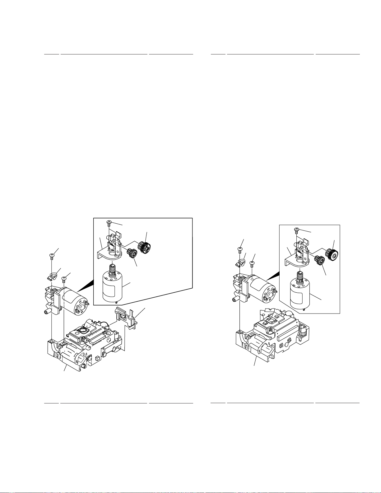
7.2 DISASSEMBLY/ASSEMBLY
7.3 BLOCK DIAGRAM
8. PANEL FACILITIES AND SPECIFICATIONS
.........................................................
...........................................................
.......................................
................................
.......................
....
80
80
80
82
84
86
PIONEER ELECTRONIC CORPORATION 4-1, Meguro 1-Chome, Meguro-ku, Tokyo 153-8654, Japan
PIONEER ELECTRONICS SERVICE, INC. P.O. Box 1760, Long Beach, CA 90801-1760, U.S.A.
PIONEER ELECTRONIC (EUROPE) N.V. Haven 1087, Keetberglaan 1, 9120 Melsele, Belgium
PIONEER ELECTRONICS ASIACENTRE PTE. LTD. 253 Alexandra Road, #04-01, Singapore 159936
c
PIONEER ELECTRONIC CORPORATION 1999
T – IZE JAN. 1999 Printed in Japan
DVL-919
1. SAFETY INFORMATION
This service manual is intended for qualified service technicians ; it is not meant for the casual do-ityourselfer. Qualified technicians have the necessary test equipment and tools, and have been trained
to properly and safely repair complex products such as those covered by this manual.
Improperly performed repairs can adversely affect the safety and reliability of the product and may
void the warranty. If you are not qualified to perform the repair of this product properly and safely, you
should not risk trying to do so and refer the repair to a qualified service technician.
WARNING
This product contains lead in solder and certain electrical parts contain chemicals which are known to the state of California to cause
cancer, birth defects or other reproductive harm.
Health & Safety Code Section 25249.6 – Proposition 65
NOTICE
(FOR CANADIAN MODEL ONLY)
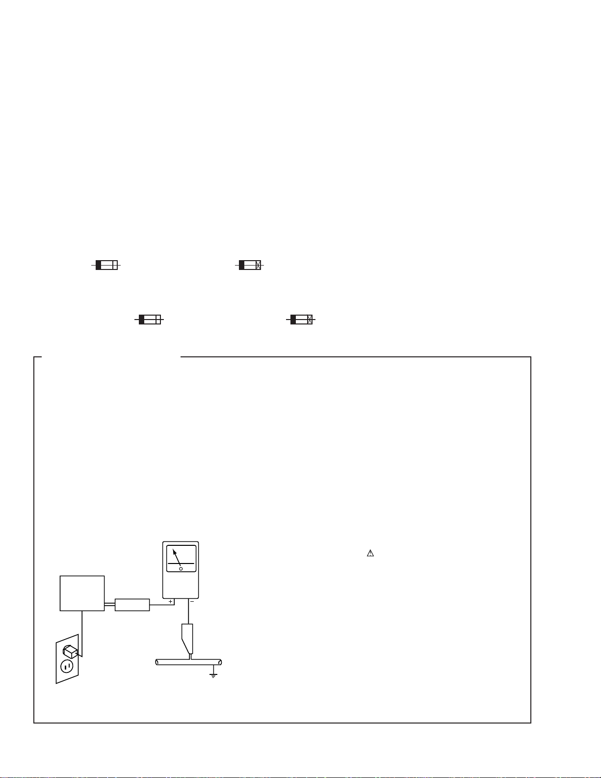
Fuse symbols (fast operating fuse) and/or (slow operating fuse) on PCB indicate that replacement parts must
be of identical designation.
REMARQUE
(POUR MODÈLE CANADIEN SEULEMENT)
Les symboles de fusible (fusible de type rapide) et/ou (fusible de type lent) sur CCI indiquent que les pièces
de remplacement doivent avoir la même désignation.
(FOR USA MODEL ONLY)
1. SAFETY PRECAUTIONS
The following check should be performed for the
continued protection of the customer and service
technician.
LEAKAGE CURRENT CHECK
Measure leakage current to a known earth ground (water
pipe, conduit, etc.) by connecting a leakage current tester
such as Simpson Model 229-2 or equivalent between the
earth ground and all exposed metal parts of the appliance
(input/output terminals, screwheads, metal overlays, control
shaft, etc.). Plug the AC line cord of the appliance directly
into a 120V AC 60Hz outlet and turn the AC power switch
on. Any current measured must not exceed 0.5mA.
Reading should
not be above
0.5mA
Earth
ground
Device
under
test
Also test with
plug reversed
(Using AC adapter
plug as required)
Leakage
current
tester
Test all
exposed metal
surfaces
ANY MEASUREMENTS NOT WITHIN THE LIMITS
OUTLINED ABOVE ARE INDICATIVE OF A POTENTIAL
SHOCK HAZARD AND MUST BE CORRECTED BEFORE
RETURNING THE APPLIANCE TO THE CUSTOMER.
2. PRODUCT SAFETY NOTICE
Many electrical and mechanical parts in the appliance
have special safety related characteristics. These are
often not evident from visual inspection nor the protection
afforded by them necessarily can be obtained by using
replacement components rated for voltage, wattage, etc.
Replacement parts which have these special safety
characteristics are identified in this Service Manual.
Electrical components having such features are identified
by marking with a
in this Service Manual.
The use of a substitute replacement component which does
not have the same safety characteristics as the PIONEER
recommended replacement one, shown in the parts list in
this Service Manual, may create shock, fire, or other hazards.
Product Safety is continuously under review and new
instructions are issued from time to time. For the latest
information, always consult the current PIONEER Service
Manual. A subscription to, or additional copies of, PIONEER
Service Manual may be obtained at a nominal charge from
PIONEER.
on the schematics and on the parts list
AC Leakage Test
2

IMPORTANT
THIS PIONEER APPARATUS CONTAINS
LASER OF CLASS 1.
SERVICING OPERATION OF THE APPARATUS
SHOULD BE DONE BY A SPECIALLY
INSTRUCTED PERSON.
LASER DIODE CHARACTERISTICS
•FOR DVD
MAXIMUM OUTPUT POWER : 7 mW
WAVELENGTH : 650 nm
•FOR CD/LD
MAXIMUM OUTPUT POWER : 5 mW
WAVELENGTH : 780-785 nm
DVL-919
Additional Laser Caution
1. The ON/OFF statuses of the side-A/B detection switch
(Lever switch connecting to the TNMB assy), slider-position
detection switches (INNER and OUTER on the PKSB assy),
loading-status detection switches (SW1, 2 and 3 on the LMSB
assy), side B inside detection switch (S901 on the BISB assy)
and CLD pickup active detection switch (S903 on the LCSB
assy) are detected by the microprocessor (IC101 in the CLDM
assy). Also the DVD pickup active detection switch (S902
on the DCSB assy) is detected by the microprocessor (IC501
in the DVDM assy).
• To permit the laser diode of CLD pickup to oscillate, it is
required to set the CLD pickup active detection switch (S903 :
OFF) and the slider-position detection switches for the LD
ACTIVE status (INNER : OFF, OUTER: OFF), and to set the
loading-status detection switches for tilt neutral state (SW1 :
ON, SW2 : OFF, SW3 : ON). As long as these requirements
are not satisfied, the laser diode will not oscillate. When the
requirements are met in any way, the laser diode can oscillate.
The laser diode oscillation will continue if pin 13 of IC801 is
shorted to GND or the emitter and collector of Q834 are shorted
each other (fault condition) in the CLDM assy.
• To permit the laser diode of DVD pickup to oscillate, it is
required to set the DVD pickup active detection switch (S902
:OFF) and each switch and a state of laser diode are contents
same as state of CLD pickup mentioned above. The laser
diode oscillation will continue if pin 13 of IC101 is shorted to
+5V (fault condition) in the DVDM assy.
In the test mode ∗, the laser diode oscillates when the micro-
processor detects a PLAY signal, or when the PLAY key is
pressed (S104 ON in the FLKY assy), with the above require ments satisfied.
2. When the cover is open, close viewing through the objective
lens with the naked eye will cause exposure to a Class 1
laser beam.
∗ : Refer to page 68.
3
DVL-919
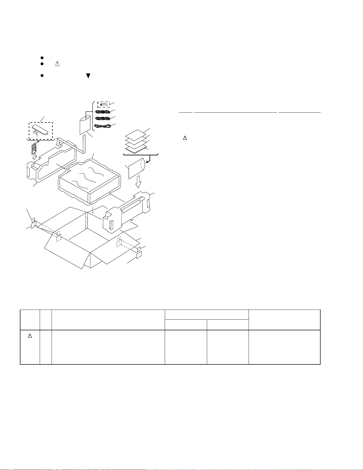
2. EXPLODED VIEWS AND PARTS LIST
NOTES:
2.1 PACKING
Parts marked by "NSP" are generally unavailable because they are not in our Master Spare Parts List.
The mark found on some component parts indicates the importance of the safety factor of the part.
Therefore, when replacing, be sure to use parts of identical designation.
Screws adjacent to mark on product are used for disassembly.
7
14
(RD/RA Type Only)
17
18
(RD/RA Type)
1
6
5
12
2
3
4
5
18
15
17
(RD/RA
Type Only)
(RD/RA Type)
8
11
10
9
13
(1) PACKING PARTS LIST
Mark No. Description Part No.
NSP 1 DRY CELL BATTERY(R6P,AA) VEM-013
2 VIDEO CORD(L=1.5m) VDE1036
3 AUDIO CORD(L=1.5m) VDE1033
4 POWER CORD See Contrast table (2)
5 POLYETHYLENE BAG Z21-038
6 REMOTE CONTROL UNIT VXX2609
(CU-DV030)
7 BATTERRY COVER VNK3703
NSP 8 CAUTION VRM1063
9 OPERA TING INSTR UCTIONS VRB1202
(English/French)
10 ERRATA VRX1031
NSP 11 WARRANTY CARD See Contrast table (2)
12 MIRROR MAT SHEET VHL1018
13 PAD F VHA1226
14 PAD R VHA1227
15 PACKING CASE See Contrast table (2)
16 • • • • •
17 REGION LABEL P1 See Contrast table (2)
18 RD/RA LABEL See Contrast table (2)
(2) CONTRAST TABLE
DVL-919/KU/CA and RD/RA are constructed the same except for the following :
Mark
No.
4 POWER CORD ADG7021 ADG7003
NSP 11 WARRANTY CARD ARY7023 ARY7025
15 PACKING CASE VHG1768 VHG1770
17 REGION LABEL P1 Not used VRW1708
18 RD/RA LABEL Not used VRW1711
Symbol and Description
KU/CA type RD/RA type
4
Part No.
Remarks
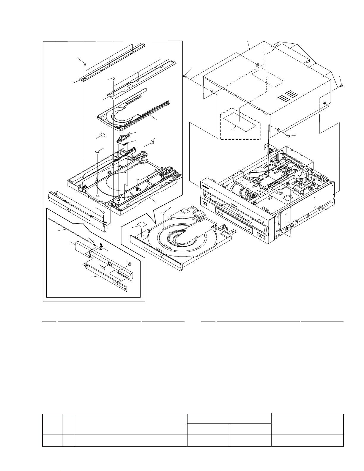
DVL-919
2.2 EXTERIOR SECTION
19
19
7
8
6
4
19
10
17
20
19
5
9
4
21
20
KU/CA Type only
1
2x12
18
13
3
11
14
16
15
12
(1) EXTERIOR SECTION PARTS LIST
Mark No. Description Part No.
1 LD TRA Y ASSY VXA2173
2 CUSHION VEC1682
NSP 3 CARRY LABEL VRW1289
4 DAMP CUSHION VEC1683
5 CD TRA Y VNK3922
6 TRAY LABEL VRW1628
7 GUIDE PLATE (R) VNE1939
8 GUIDE PLATE (L) VNE1938
9 LOCK PLATE VNL1703
10 LOCK PLATE SPRING VBH1188
Mark No. Description Part No.
11 TRAY PANEL VNK4355
12 DVD DOOR VNK4356
13 DOOR SPRING VBH1248
14 DOOR HOLDER VNL1817
15 DAMPER ASSY VXA1999
16 DV D PL ATE VAM1075
17 BONNET CASE S VXX2561
18 DOOR SHAFT VLL1506
19 SCREW BBZ30P080FMC
20 SCREW BCZ40P060FZK
21 65 LABEL See Contrast table (2)
(2) CONTRAST TABLE
DVL-919/KU/CA and RD/RA are constructed the same except for the following :
Mark
No.
Symbol and Description
KU/CA type RD/RA type
Part No.
Remarks
21 65 LABEL ARW7050 Not used
5
DVL-919
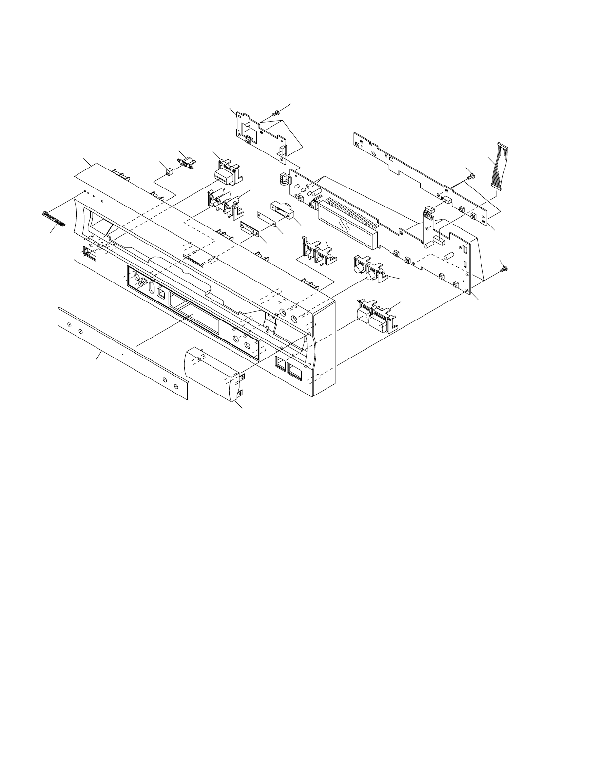
2.3 FRONT PANEL SECTION
11
16
4
16
10
15(2/2)
7
14(1/3)
14(2/3)
3
16
1
2
12
5
8
14(3/3)
6
9
15(1/2)
÷
FRONT PANEL SECTION PARTS LIST
Mark No. Description Part No.
1 FLKY ASSY VWG2005
NSP 2 PWSB ASSY VWG1994
NSP 3 DILB ASSY VWG1995
4 FLEXIBLE CABLE (14P) VDA1638
5 NAME PLATE PAM1776
6 LED LENS PNW2019
7 ILLUMINATION FILTER VEC1950
8 FL LENS VEC2015
9 POWER BUTTON VNK4101
10 ILLUMI HOLDER VNK4098
13
Mark No. Description Part No.
11 ILLUMINATION LENS VNK4168
12 FRONT PANEL VNK4352
13 SUB PANEL VNK4415
14 PLAY BUTTON VNK4354
15 OPERATION BUTTON VNK4349
16 SCREW BBZ30P080FMC
6
DVL-919
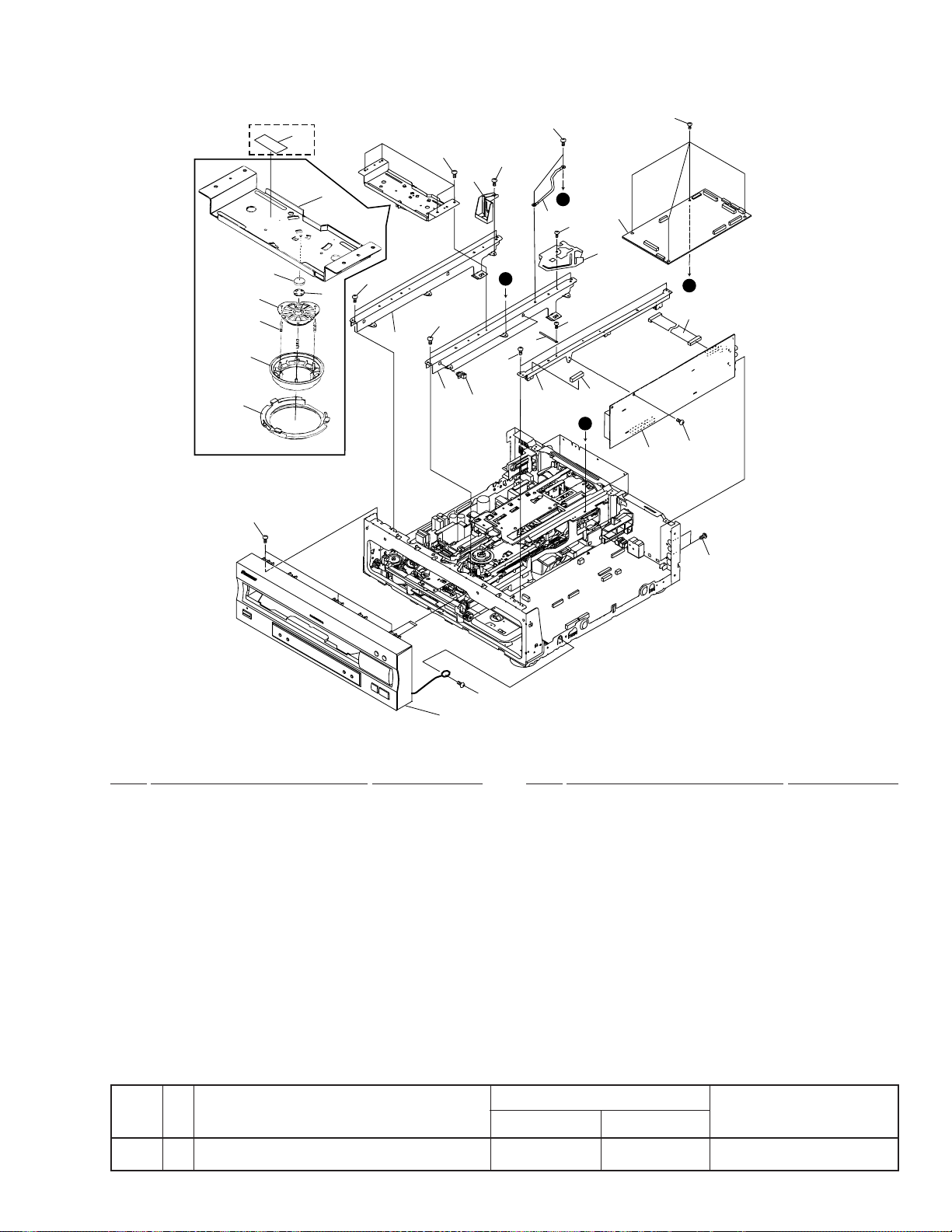
2.4 TOP VIEW SECTION
KU/CA
25
Type
only
1
2
6
5
x3
4
7
23
3
24
22
24
24
22
15
14
24
24
24
B
16
24
13
A
24
12
20
26
B
24
8
A
19
24
18
(1) TOP VIEW SECTION PARTS LIST
Mark No. Description Part No.
1 CENTER PLATE VNE2127
2 RUBBER MAT VEB1114
3 THRUST HOLDER VNL1663
4 CLAMPER VNL1648
5 CLAMPER SPRING VBH1192
6 CLAMPER HEAD VNL1649
7 CLAMPER HOLDER VNL1788
8 DVDM ASSY VWS1377
9 • • • • •
10 • • • • •
11 • • • • •
12 CORD CLAMPER RNH-184
13 CABLE HOLDER VEC1958
24
24
Refer to
"2.3 FRONT PANEL SECTION"
Mark No. Description Part No.
NSP 14 CORNER POST DEC1212
15 SHIPPING CAM VNL1729
NSP 16 CORD WITH PLUG DE007VF0
17 • • • • •
18 GYCB ASSY VWV1633
19 HOUSING ASSY(13P) VKP2196
NSP 20 PCB-HOLDER VNE2164
21 • • • • •
NSP 22 CENTER ANGLE VNE2126
23 SCREW IBZ30P080FMC
24 SCREW BBZ30P080FMC
25 FUSE CAUTION LABEL See Contrast table (2)
26 CUSHION VEC1982
(2) CONTRAST TABLE
DVL-919/KU/CA and RD/RA are constructed the same except for the following :
Mark
No.
25 FUSE CAUTION LABEL VRW1695 Not used
Symbol and Description
KU/CA type RD/RA type
Part No.
Remarks
7
DVL-919
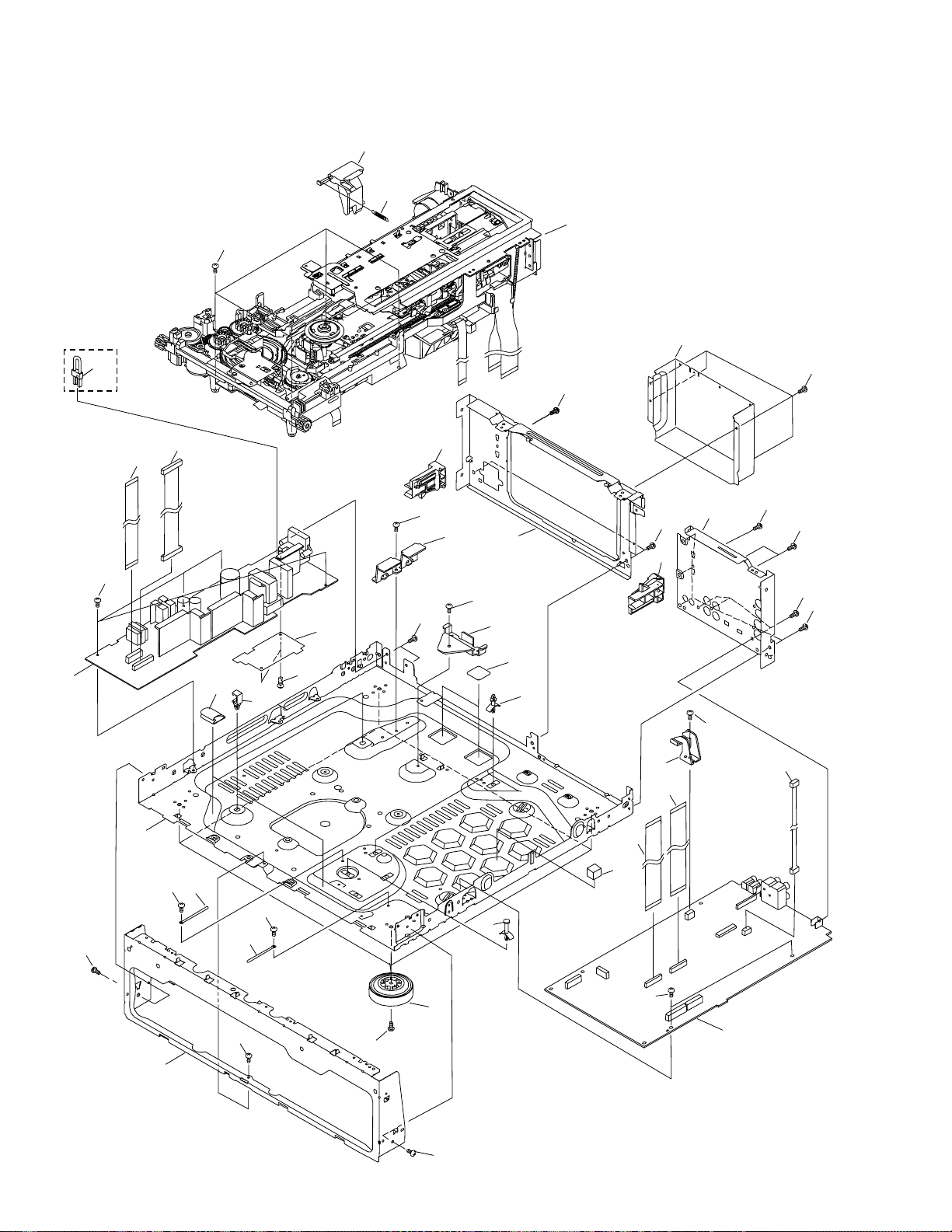
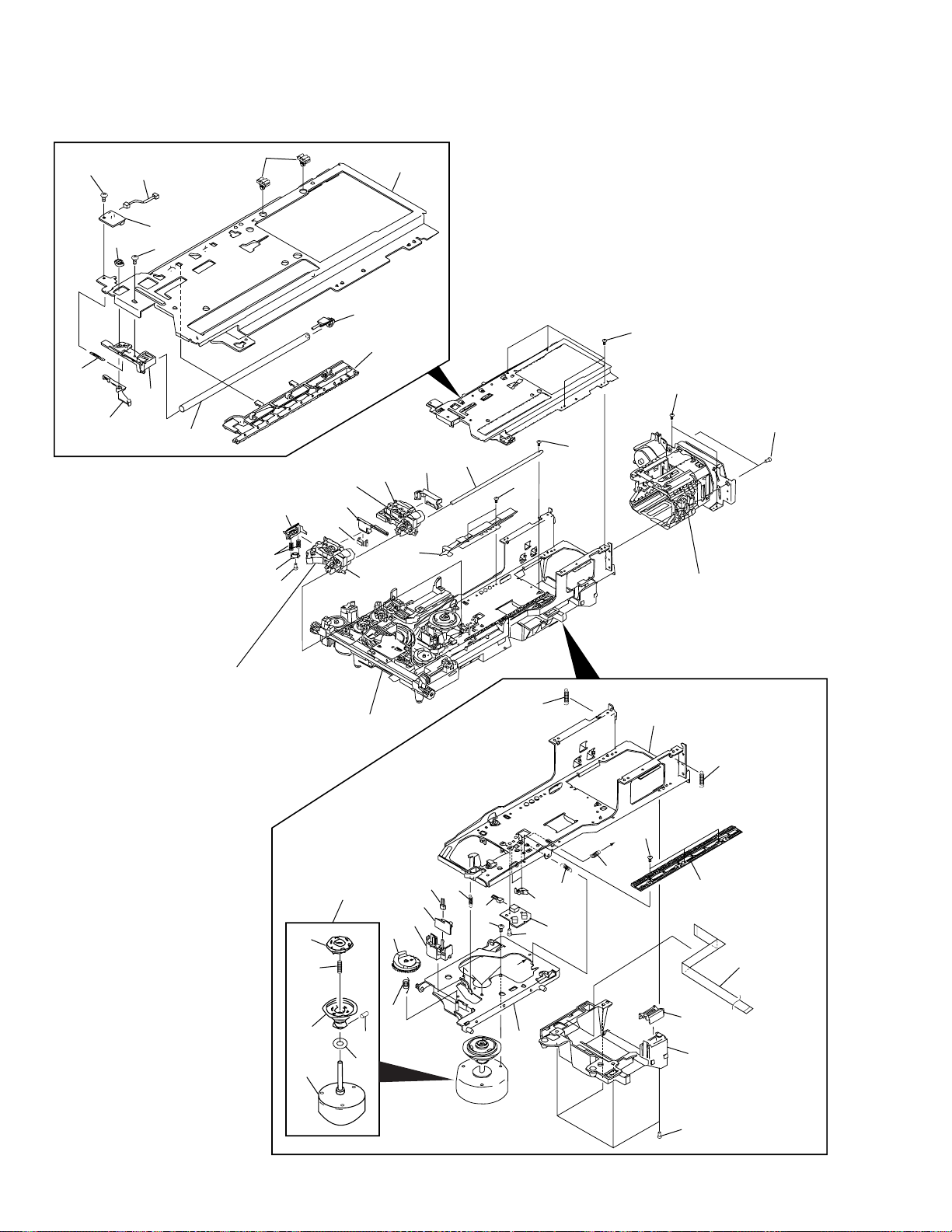
2.5 BOTTOM VIEW SECTION
20
RD/RA Type
only
36
32
16
15
33
21
28
32
19
26
32
7
32
9
Refer to
"2.6 LOADING MECHANISM SECTION"
18
29
32
32
32
28
27
32
32
32
32
6
1
32
17
32
11
3
8
32
8
32
34
2
32
10
4
32
22
23
23
35
5
32
25
13
32
8

(1) BOTTOM VIEW SECTION PARTS LIST
DVL-919
Mark No. Description Part No.
NSP 1 CHASSIS VNA1887
2 INSULATOR ASSY VXA2356
3 PCB HINGE VEC1174
NSP 4 PCB SPACER AEC1188
NSP 5 CIRCUIT BOARD SPACER VEC1957
6 POWER SUPPLY ASSY See Contrast table (2)
7 SHEET P VEC1874
8 CORD CLAMPER RNH-184
NSP 9 STOPPER VNE2088
10 SPACER VEC1939
11 SHELL CLIP DEC1184
12 • • • • •
13 CLDM ASSY VWS1358
14 • • • • •
15 HOUSING ASSY (14P) VKP2151
16 FLEXIBLE CABLE(15P) VDA1644
NSP 17 PANEL HOLDER VNA1686
NSP 18 MECHANISM ASSY VWT1149
NSP 19 CAM HOLDER L VNE2089
20 SHIPPING LEVER VNL1728
21 SHIPPING SPRING VBH1275
Mark No. Description Part No.
NSP 22 CAM HOLDER R VNE2090
23 FLEXIBLE CABLE(22P) VDA1652
24 • • • • •
25 HOUSING ASSY (4P) VKP2195
26 REAR PANEL R VNA1892
27 REAR PANEL L VNA2027
28 TRAY STOPPER VNL1707
29 REAR COVER See Contrast table (2)
30 • • • • •
31 • • • • •
32 SCREW BBZ30P080FMC
33 SCREW BBZ30P100FMC
34 RIVET RBM-003
NSP 35 SPACER VEC1989
NSP 36 HOUSING ASSY See Contrast table (2)
(2) CONTRAST TABLE
DVL-919/KU/CA and RD/RA are constructed the same except for the following :
Mark
No.
6 POWER SUPPLY ASSY VWR1286 VWR1287
29 REAR COVER VNA2028 VNA2056
NSP 36 HOUSING ASSY Not used VKP2189
Symbol and Description
KU/CA type RD/RA type
Part No.
Remarks
9
DVL-919
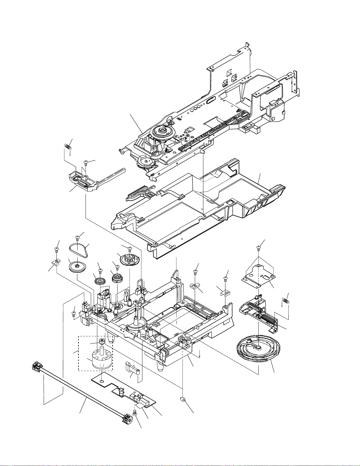
2.6 LOADING MECHANISM SECTION
Refer to
"2.7 SERVO MECHANISM SECTION (1/2)"
2
B
4
3
6
7
11
3
1
3
5
10
3
8
3
3
9
B
3
3
25
26
3
2324
A
22
10
12
15
13
14
18
A
20
21
17
16
3
19

÷
LOADING MECHANISM SECTION PARTS LIST
DVL-919
Mark No. Description Part No.
1 Clamp Cam B VNL1765
2 CDP Spring VBH1191
3 Screw Z39-019
4 CD Plate VNL1685
5 Rubber Belt VEB1184
6 Gear Pulley VNL1662
7 Slider (L) VNL1665
8 Twin Gear VNL1626
9 Center Gear VNL1660
10 Double Gear VNL1661
11 Screw BMZ26P040FMC
12 Loading Motor Assy VXX2045
13 Carriage Motor VXM1033
NSP 14 Motor Pulley VNL1630
15 Synchro Gear Assy VXA2105
Mark No. Description Part No.
16 Flexible Cable (10P) VDA1645
NSP 17 LMSB Assy VWG1554
18 MB Switch Lever VNL1664
19 Roller VNL1042
20 Mechanism Base VNK3239
21 Cam Gear VNL1625
22 Cam Plate VNL1631
23 CAS Spring VBH1190
24 Shaft Holder VNE1942
25 CAM Holder VNE2032
26 Slider (R) VNL1666
11
DVL-919
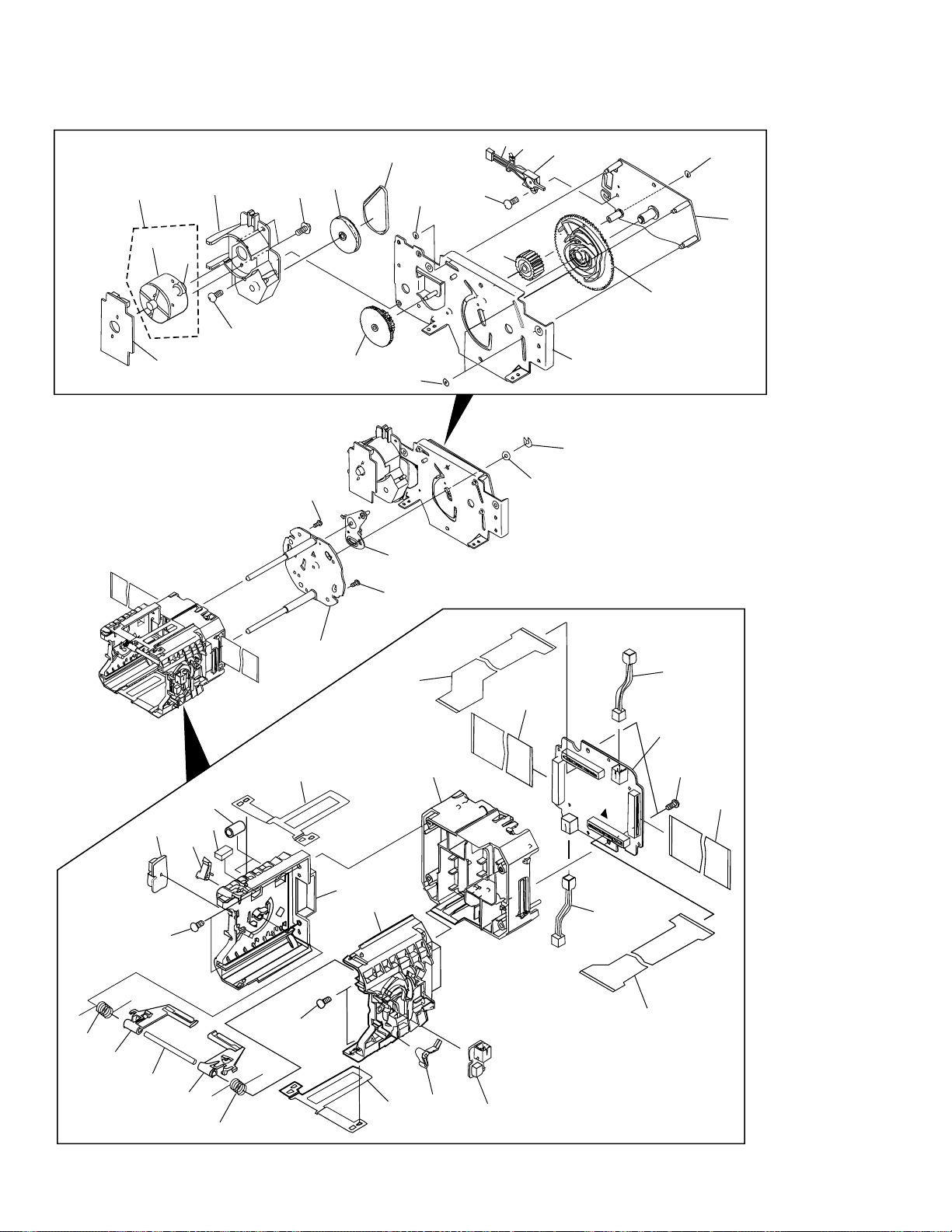
2.7 SERVO MECHANISM SECTION (1/2)
1
2
5
6
8
7
4
14
13
55
9
11
10
12
Refer to
"2.9 DVD CARRIAGE ASSY"
23
24
25
26
Refer to
"2.10 CLD CARRIAGE ASSY"
Refer to
"2.6 LOADING MECHANISM SECTION"
57
21
22
20
18
19
16
17
15
28
58
58
Refer to
"2.8 SERVO MECHANISM
SECTION (2/2)"
27
28
12
52
47
49
48
56
50
51
46
45
44
43
42
41
38
40
33
A
34
35
36
37
39
A
32
29
30
53
31
15

÷
SERVO MECHANISM SECTION (1/2) PARTS LIST
DVL-919
Mark No. Description Part No.
1 Mini Clamp VEC2030
2 Screw BBZ26P060FMC
3 • • • • •
4 Tilt Base (Upper) VNE2062
5 Housing Assy (2P) VKP2136
NSP 6 BISB Assy VWG1796
7 Screw BPZ20P040FZK
8 B Cam VNL1725
9 Support Spring VBH1273
10 SW Lever B VNL1723
11 Shaft Holder VNL1724
12 CA Shaft (Upper) VLL1486
13 CA Rack (Upper) VNL1722
14 Shaft Stay VNL1726
15 Screw BBZ30P080FMC
16 Screw PPZ20P060FMC
17 CA Shaft (Lower) VLL1496
18 TAN Guide VNE2061
19 FPC Holder A VNL1751
20 DVD Carriage Assy VWT1146
21 FPC Holder B VNL1801
22 CLD Carriage Assy VWT1141
23 CA Guide VNL1668
24 TAN Spring (B) VBH1264
25 TAN Lever (B) VNL1669
Mark No. Description Part No.
31 Flexible Cable Cover VNL1727
32 Motor Base VNE1941
33 Screw IBZ26P060FMC
34 Tilt Spring VBH1263
35 Thrust Spring VBH1245
36 CA Switch Lever VNL1644
NSP 37 PKSB Assy VWG1555
38 Housing Assy (3P) VKP2045
39 Screw IBZ26P120FMC
40 Screw PMA30P050FMC
41 Tilt Spring B VBH1287
42 Housing Assy (3P) VKP2046
NSP 43 FG Assy VWG1556
44 FG Base VNL1781
45 Tilt Cam VNL1643
46 Tilt Cam Spring VBH1243
47 PRC Hub VNL1684
48 Centering Spring VBH1269
49 R Turn Tab le Assy VXA2354
NSP 50 Oil Stopper VBF1002
51 Screw ZMD30H030FBT
NSP 52 Spindle Motor VXM1057
53 Cover S VNL1780
54 • • • • •
55 Screw BBZ30P050FZK
26 Screw PMZ20P060FZK
27 Tilt Base (Under) VNL1711
28 Tilt Rear Spring VBH1274
29 CA Rack (Lower) VNL1712
30 Flexible Cable (6P) VDA1642
56 Spindle Motor Assy VXX2579
57 FPC Holder VNL1789
58 Screw BCZ30P080FMC
13
DVL-919
2.8 SERVO MECHANISM SECTION (2/2)
8
40
4
2
3
5
1
7
6
11
35
35
36
13
9
39
10
14
12
33
35
15
28
5
16
5
17
18
25
38
37
27
26
26
5
24
34
20
19
21
5
22
20
14
30
31
32
31
30
5
27
25
29
23
÷
SERVO MECHANISM SECTION (2/2) PARTS LIST
Mark No. Description Part No.
NSP 1 TNMB Assy VWG1793
NSP 3 Motor Pulley VNL1630
2 Carriage Motor VXM1033
4 Motor Holder VNL1717
5 Screw BBZ30P080FMC
DVL-919
Mark No. Description Part No.
NSP 21 CNNB Assy VWG1792
22 Flexible Cable (27P) VDA1643
23 PU FPC-A VNP1582
24 PCB Holder VNL1716
25 FC Guide VNE2059
6 Screw BMZ26P040FMC
7 Gear Pulley VNL1662
8 Rubber Belt VEB1184
9 Housing Assy (3P) VKP2137
10 Lever Switch DSK1003
11 Middle Gear VNL1720
12 Turn Panel Assy VXA2337
13 Gear S VNL1719
14 Turn Cam Gear VNL1718
15 Swing Plate Assy VXA2289
16 Turn Lever Assy VXA2292
17 Turn Plate Assy VXA2290
18 PU FPC-B VNP1583
19 Flexible Cable (26P) VDA1653
20 Connector Assy PG02KK-E10
2.9 DVD CARRIAGE ASSY
8
4
7
5
7
2
1
3
26 PU Holder VNL1715
27 SW Lever C VNL1714
NSP 28 LCSB Assy VWG1795
NSP 29 DCSB Assy VWG1794
30 FC Arm Spring VBH1272
31 FC Arm VNL1713
32 Tilt Shaft VLL1175
33 E Ring YE30FUC
34 Washer WA42D080D050
35 Washer WT26D070D050
36 Screw PMA26P060FMC
37 Cushion VEC1917
38 Tube VEB1273
39 Binder Z09-056
40 Loading Motor Assy VXX2045
2.10 CLD CARRIAGE ASSY
6
5
6
4
7
1
2
6
This part is no service part.
÷
DVD CARRIAGE ASSY PARTS LIST
Mark No. Description Part No.
1 CA Gear (A) VNL1782
2 CA Gear B Assy VXX2471
3 Slider Motor Assy VXX2472
4 Motor Holder VNL1779
5 Thrust Holder VBK1058
6 CA Guide B VNL1721
7 Screw BBZ20P050FZK
8 Screw PMA20P033FUC
3
This part is no service part.
÷
CLD CARRIAGE ASSY PARTS LIST
Mark No. Description Part No.
1 CA Gear (A) VNL1782
2 CA Gear (B) VNL1639
3 Slider Motor Assy VXX2472
4 Motor Holder VNL1779
5 Thrust Holder VBK1058
6 Screw PBZ20P050FMC
7 Screw PMA20P033FUC
15
1
23
4
DVL-919
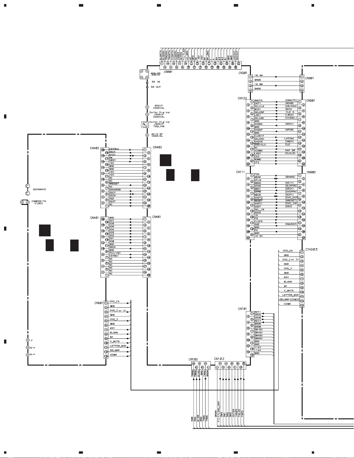
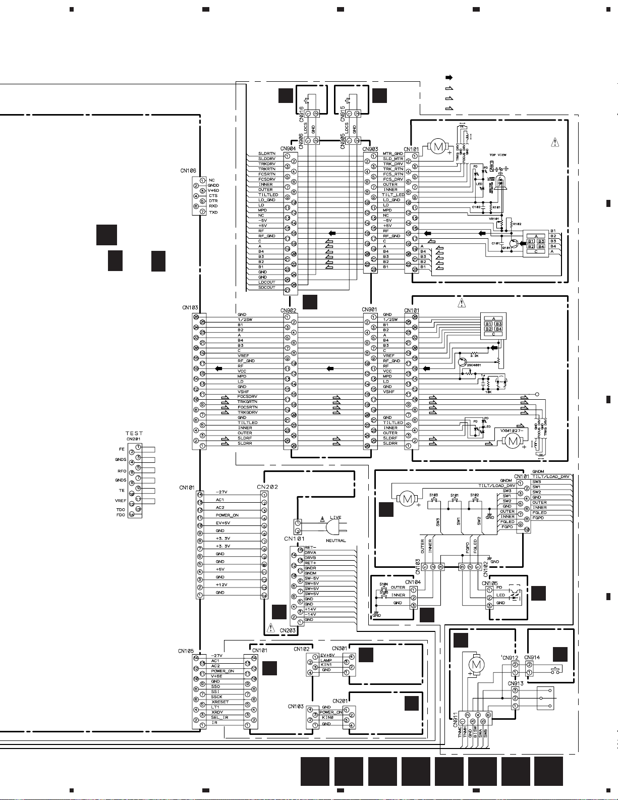
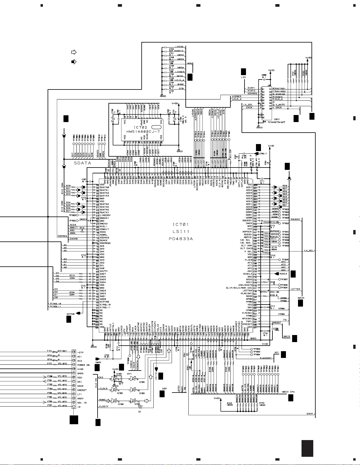
3. SCHEMATIC DIAGRAM
3.1 OVERALL WIRING DIAGRAM, LMSB, PKSB, FG, CNNB, TNMB, DCSB, LCSB
and BISB ASSEMBLIES
A
J
B
( )
J
1/3 –
CLDM ASSY
(VWS1358)
J
3/3
K
( )
K
1/2,
GYCB ASSY
(VWV1633)
C
K
2/2
D
16
1234
5
678
DVL-919
Note : When ordering service parts, be sure to refer to "EXPLODED VIEWS and PARTS LIST" or "PCB P ARTS LIST".
: RF SIGNAL ROUTE
(F)
: FOCUS SERVO LOOP LINE
(T)
: TRACKING SERVO LOOP LINE
(S)
: SLIDER SERVO LOOP LINE
CLD CARRIAGE ASSY
(VWT1141)
OE IC
(T)
(T)
(F)
(F)
(F)
(F)
DVD CARRIAGE ASSY
(VWT1146)
FOR 232C
I
( )
I
1/3 –
DVDM ASSY
(VWS1377)
I
3/3
G
LCSB ASSY
(VWG1795)
S903 S902
(T)
(T)
(F)
(F)
(F)
(F)
CNNB ASSY
D
(VWG1792)
F
DCSB ASSY
(VWG1794)
SLIDER MOTOR
ASSY
VXX2472
A
B
OE IC
VXX2045
M
(F)
(T)
(F)
(T)
(S)
(S)
PKSB ASSY
B
(VWG1555)
(S)
SLIDER MOTOR ASSY
VXX2472
TNMB ASSY
E
(VWG1793)
VXX2579
SPINDLE MOTOR ASSY
(F)
(T)
(F)
(T)
(S)
D101
GP1S24
C
FG ASSY
(VWG1556)
BISB ASSY
(VWG1796)
H
S901
C
D
(F)
(T)
(F)
(T)
(S)
(S)
(VWR1286:KU/CA)
(VWR1287:RD/RA)
(F)
(T)
(F)
(T)
(S)
(S)
AC POWER CORD
(ADG7021:KU/CA)
(ADG7003:RD/RA)
LOADING MOTOR ASSY
A
LMSB ASSY
(VWG1554)
POWER SUPPLY ASSY
O
N
L
FLKY ASSY
(VWG2005)
DILB ASSY
(VWG1995)
PWSB ASSY
(VWG1994)
GFEDCBA
5
6
7
H
8
17
1
DVL-919
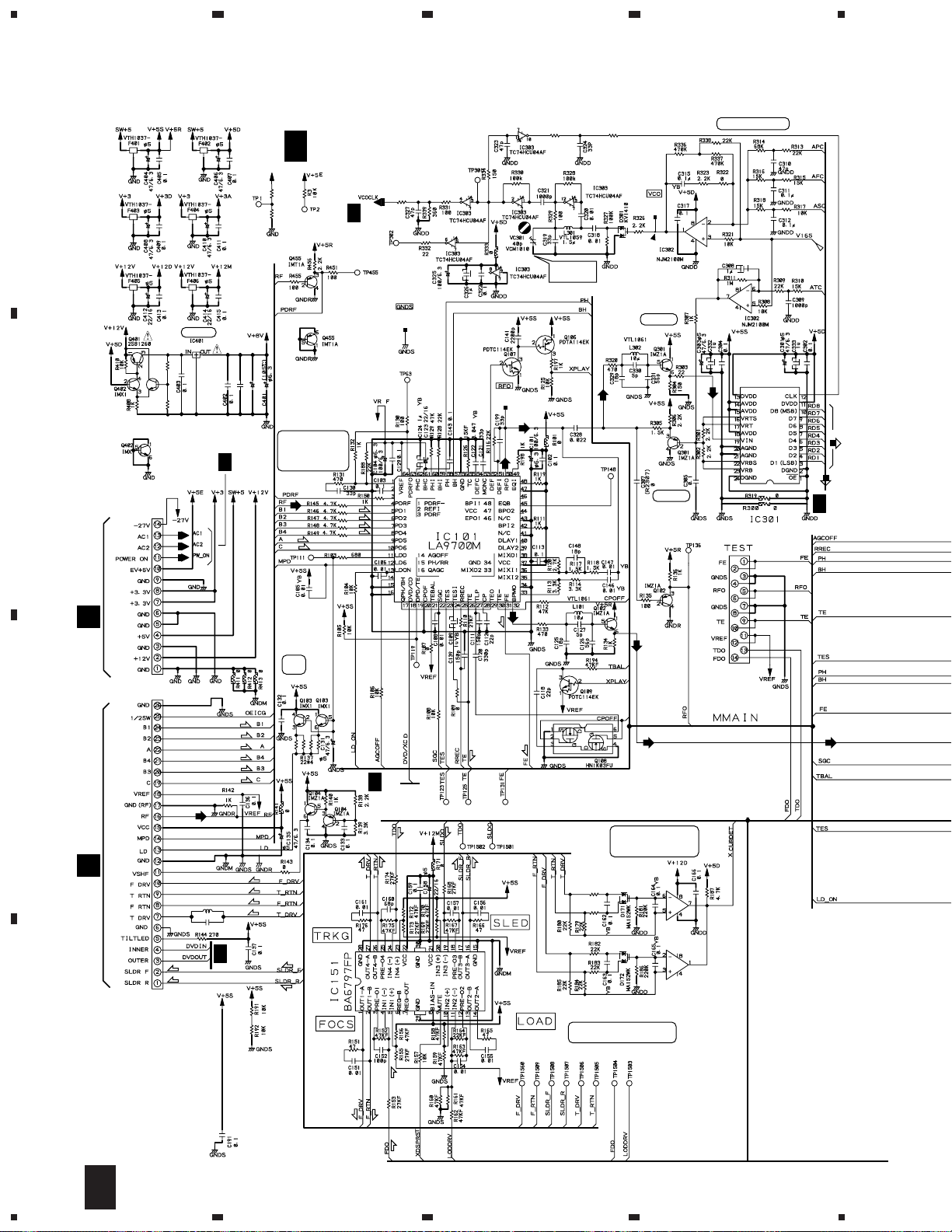
3.2 DVDM ASSY (1/3)
A
4
2
3
Q403
IMX1
B
S14B-PH-SM3
CN101
+8V Reg.
BA178M08FP
R407 10k R409 12k
23
VCO Offset
adj.
5W
VTL1074
L342
(6/6)
VKF1001
TP300
BUFFER
BUFFER
VTL1074
L335
VKF1001
TP100
(5/6)
(1/6)
(4/6)
I
R1
33k
R2
22k
1µ
100/16
C416
C417
47/10
IC101:
I
2/3
(T)
(T)
DVDM ASSY
1/3
(VWS1377)
I
PRE SERVO
PROCESSOR
for DVD
RF SIGNAL
(F)
(F)
(F)
(F)
2/3
VTL1074
L340
VKF1001
TP400
(2/6)
(3/6)
5W
1/2
LPF
4
IC302(1/2):VLXO D
2/2
ADC1175CIJMX
(ROM)
I
(ROM)
2/3
CN202
O
LD
DRV.
CN103
VKN1430
(F)
(F)
(T)
(F)
C
CN902
D
L100
C100
(S)
(S)
(F)
(T)
(F)
(T)
(F)
(T)
47µ
YB
1µ
I
3/3
(S)
(S)
I
3/3
(T)
(T)
(T)
(F)
5W
(F)
(T)
(S)
(S)
(S)
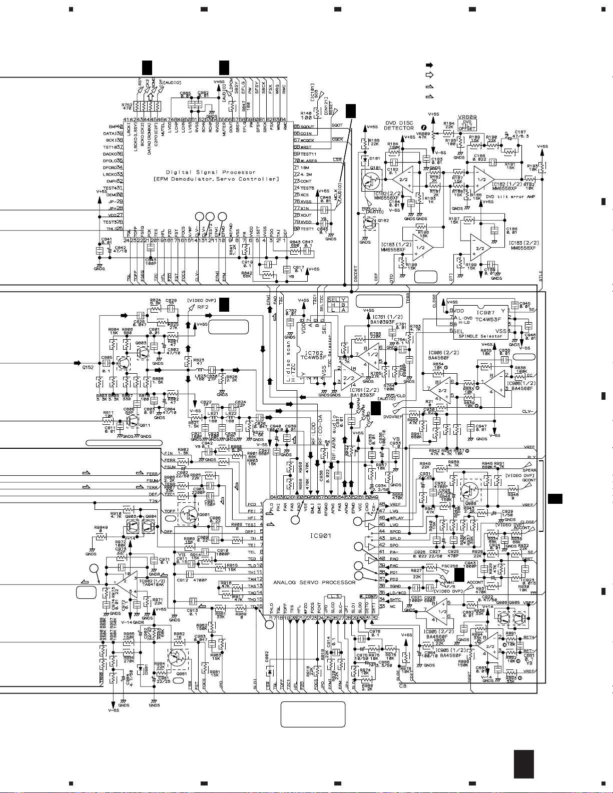
IC171:
FOCS. EeTRK. DRIVE
CURRENT DETECTOR
R177
22k
R178
22k
IC151:TRK.,FOCS., SLD. and
LOADING DRIVER
2/2
IC171
BA10393F
1/2
IC171
BA10393F
CN201
VKN1324
D
(F)
18
I
1/3
(F)
(F)
(F)
1234
IC506
TC74VHCT245AFT
AGCOFF
VKF1001
TP200
5
678
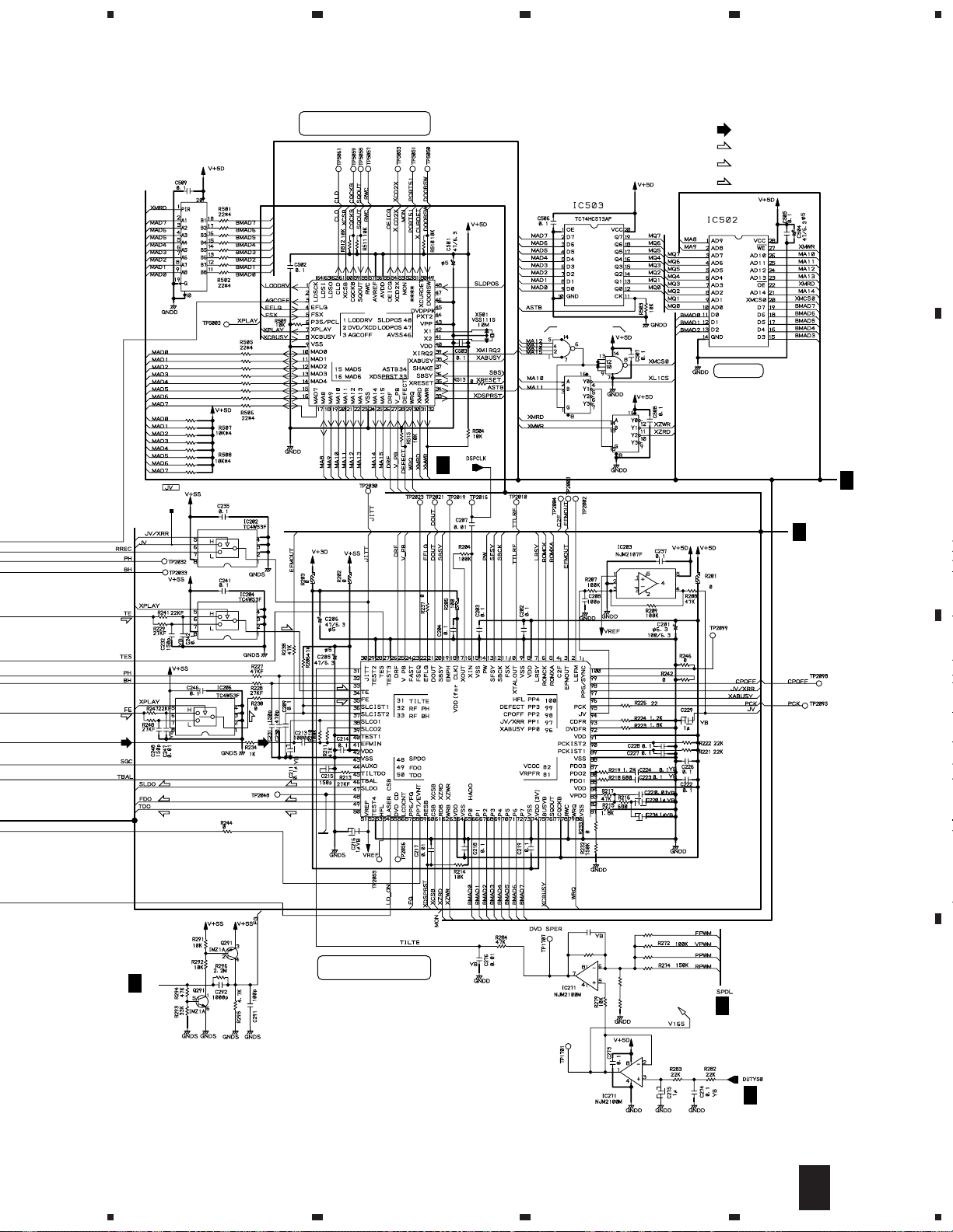
DVL-919
IC501:MECHANISM CONTROL
MICROCOMPUTER for DVD
IC501
PD4889A
IC504
TC74VHC20FT
IC505(1/2)
TC74VHC139FT
IC505(2/2)
I
3/3
TC74VHC139FT
: RF SIGNAL ROUTE
(F)
: FOCUS SERVO LOOP LINE
(T)
: TRACKING SERVO LOOP LINE
(S)
: SLIDER SERVO LOOP LINE
SRM2B256SLMX70
256K SRAM
FSX,EFLG,SLDPOS,
DVDPRK,SHAKE,
SCKI,SSI1,SSO1,CLD
I
2/3
XRESET,SBSY,PW,
SFSY,SBCK,MON,
C2F,FG
A
B
I
3/3
(T)
(F)
LD-ON
(T)
(T)
(F)
(F)
IC201
LC78650NE
C
(S)
(F)
CLDFG
I
3/3
(S)
(F)
(T)(T)
SPDO
IC201:Digital Signal Processor
(Servo Control for DVD)
C271 2200p
R277
220k
2/2
R271 470k
68k
R275
330k
R276
1/2
R273 330k
I
2/3
D
I
2/3
1/3
I
5
6
7
8
19
1
DVL-919
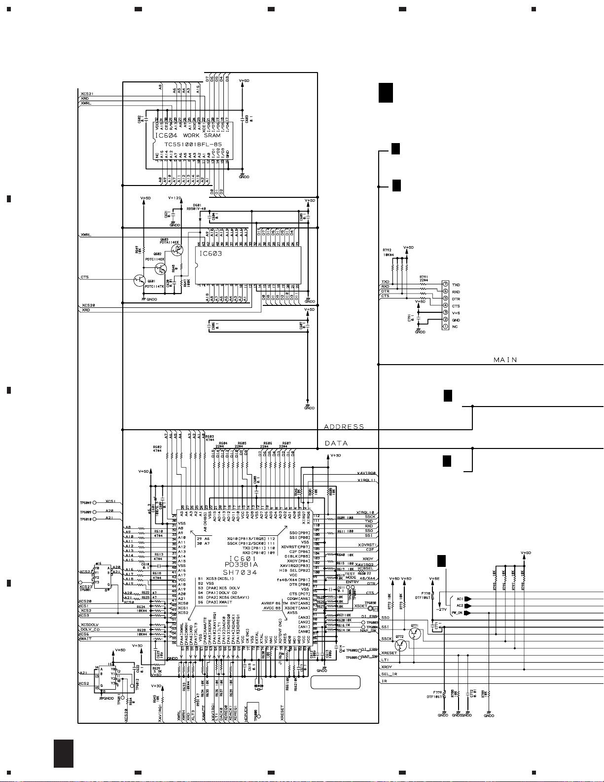
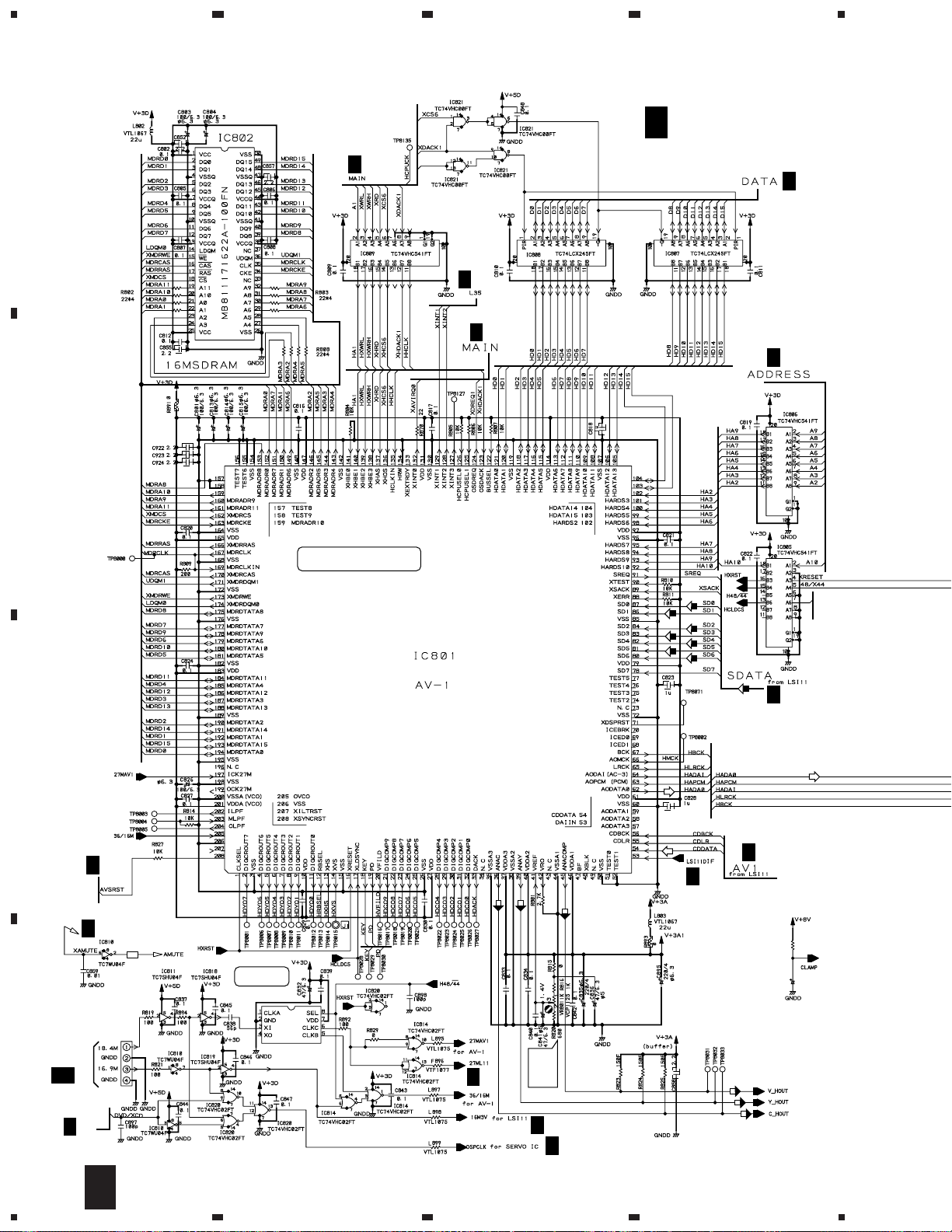
3.3 DVDM ASSY (2/3)
23
4
I
DVDM ASSY
A
(1M)
5W
5W
5W
B
VYW1612
MBM29F400TA-70PF
PGM 4MFLASH MEMORY
2/3
(VWS1377)
I
1/3
C2F,XRESET
I
3/3
XCSDOLV,DOLV-CD,XWRL,XWRH,
XRD,XLT3,XAMUTE,XDREQ1,CDGM,
HCPUCK,IR,SEL-IR,XDVRST1,
XAVIRQ0,48/X44,HIBSEL,XCS6,
XDACK1,NAP SW,C2F
CN106
VKN1411
I
A2-A10
DATA
I
I
1/3
3/3
3/3
ADDRESS
C
IC605(1/2)
TC74VHC139FT
5W
5W
D
IC605(2/2)
TC74VHC139FT
X602
VSS1114
20MHz
SYSTEM CONTROL
MICROCOMPUTER
Q771,Q772:
PDTC114TK
20
2/3
I
1234
5
: AUDIO SIGNAL ROUTE
(ROM)
: ROM DATA SIGNAL ROUTE
I
3/3
SDATA
(ROM)(ROM)
(ROM)
678
DVL-919
A
I
3/3
I
1/3
3/3
B
I
I
3/3
I
1/3
(ROM)
(ROM)
DRAM
I
1/3
I
1/3
VKN1418
CN105
I
3/3
MONITOR OUTPUT
SERVO
I
3/3
I
1/3
C
I
3/3
I
3/3
I
3/3
I
3/3
L
CN101
5
1/3
I
TC74VHC14FT
I
3/3
6
7
I
1/3
I
2/3
8
21
D
1
DVL-919
23
4
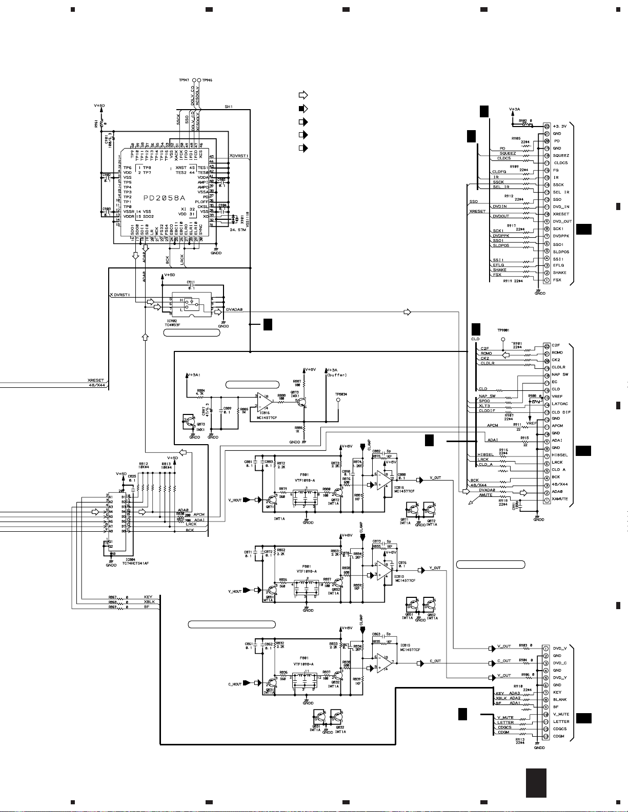
3.4 DVDM ASSY (3/3)
A
B
(1/4)
(2/4)
I
2/3
(4/4)
(3/4)
I
2/3
I
2/3
I
DVDM ASSY
3/3
(VWS1377)
I
2/3
I
2/3
AUDIO and VIDEO DECODE for
DVD(MPEG2)/VIDEO CD(MPEG)
(ROM)
MB86371C
(ROM)
CLDCS
2/3
I
C
I
I
2/3
(Y)
(C)
I
2/3
F952
(2/3)
VTF1080
CLOCK
GENERATOR
(1/4)
(COM)
I
2/3
2/3
R845
C892
4.7
47/10
(1/4)
(4/4)
(3/4)
Video
Output
I
2/3
Level
Adj.
I
2/3
I
(COM)
(Y)
(C)
1/3
S4B-PH-SM3
CN801
22
2/3
J
I
1/3
CN201
3/3
I
D
(3/3)
(1/3)
(3/4)
(2/4)
IC813
CY2081SL-611
(4/4)
(2/4)
1234
5
678
DVL-919
: AUDIO SIGNAL ROUTE
IC901
(ROM)
: ROM DATA SIGNAL ROUTE
(COM)
: COMPOSITE VIDEO SIGNAL ROUTE
(Y)
: Y SIGNAL ROUTE
(C)
: C SIGNAL ROUTE
I
1/3
I
2/3
CN902
VKN1426
A
CN111
1/3
J
B
DATA SELECTOR SW
I
HIBSEL,48/X44,XRESET,XLT3
IC816,Q873:BUFFER
1/2
(COM)
(Y)
2/3
L.P.F.
L.P.F.
(COM)
(Y)
I
2/3
R958
22
CN901
VKN1426
CN122
I
1/3
2/3
J
2/2
(COM)
C
1/2
(Y)
IC815,816(2/2):VIDEO AMP.
Q871,872,851,852,831,832:BUFFER
(C)
L.P.F.
(COM)
2/2
(C)
(C)
(C)
(Y)
CN903
S13B-PH-SMB
CN601
D
I
2/3
3/3
I
5
6
7
8
2/2
K
23
1
DVL-919
23
4
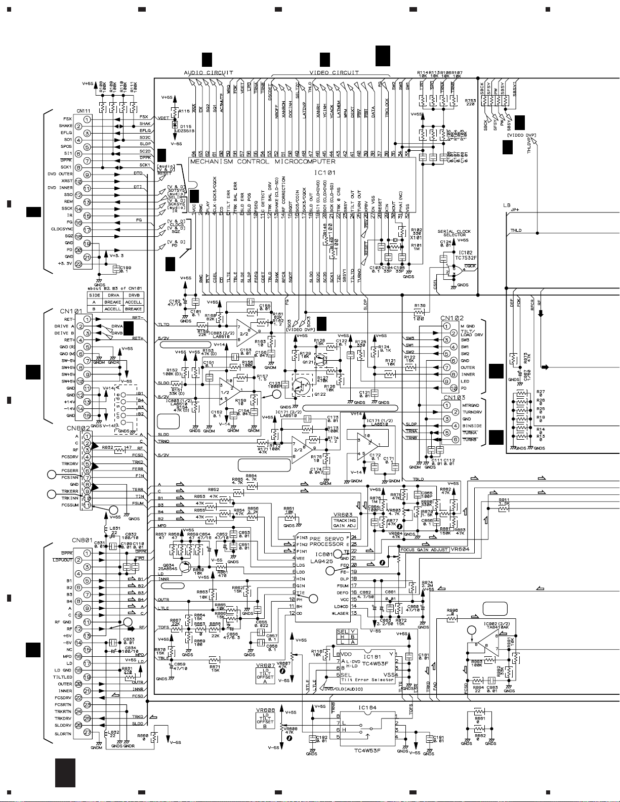
3.5 CLDM ASSY (1/3)
A
CN902
3/3
I
B
CN203
O
J
3/3
2/3,3/3
J
J
3/3
J
TILT/LOARD DRIVE
J
2/3
2/3
2PB709A
J
J
3/3
3/3
PD0266A2
J
CLDM ASSY
1/3
(VWS1358)
X101:9MHz
VSS1040
J
3/3
J
CN101
A
3/3
SLDR.
DRIVE
1
PDTC124EK
Q121,122:FG SIGNAL WAVE FORMER
CN911
E
TURN
7
C
10
11
(F)
(F)
(F)
(F)
(T)
(T)
12
(T)
(T)
(F)
(F)
(F)
(F)
LD DRV.
CN904
MECHANISM DRIVE
(F)
(F)
(T)
(T)
20
9
22
(T)
(T)
(T)
(T)
(F)
(F)
(F) (F)
(T)
(F)
(T)
(T)
(F)
9
FOCUS
DRIVE
(T)
(T)
(F)
D
(T)
(F)
(F)
D
24
1/3
J
1234
(F)
(T)
5
678
DVL-919
Q803,Q811:
2PD601A
J
2/3
IC908
LC78625E
14
13 11
Q152: RF AMP.
Q803: BUFFER
J
J
2/3
3/3
: RF SIGNAL ROUTE
: AUDIO SIGNAL ROUTE
(F)
: FOCUS SERVO LOOP LINE
(T)
: TRACKING SERVO LOOP LINE
Q181:
PDTC124EK
2/3
J
1SS355
2PB709A
IC183:
BUFFER
TRK. ZERO.CROS
COMPARATOR
(F)
A
B
2SC3082K
RF CORRECTION ON/OFF/SW
(F)
(T)
1
(T)
TRK.
DRIVE
(F)
(T)
2PD601A
BUFFER
2/3
J
(F)
(F)
(T)
5W
PDTC124EK
(T)
(T)
(F)
(T)
60
LA9430M
(FCS.,TRK. and SPDL.)
48
40
38
37
Q908: PDTC124EK
3/3
J
3/3
J
C
16
5
1SS355
Q981: PDTA124EK
1SS355
5W
D
Q903–906: LIMITER
IC905(2/2): BUFFER
IC905(1/2): SPDL. ERR.
Q908: SPDL. GAIN CONT.
6
7
Q905,Q906: 2PD601A
1/3
J
8
25
1
DVL-919
3.6 CLDM ASSY (2/3)
A
CN801
3/3
I
B
23
1/3
J
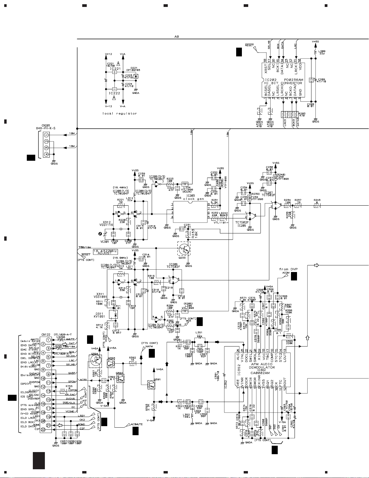
IC221:
NJM78L08A
IC222:
NJM79L08A
IC203:
CY2081SL-611
4
C
CN901
3/3
I
18.432MHz
20p
VCM-008
1/3
J
16MHz
1/3
J
1/3
J
1/3
J
Q391-Q393:
J
1/3
2PD601A
J
1/3
1/3
J
D
26
2/3
J
1234
J
5
CLDM ASSY
2/3
(VWS1358)
678
DVL-919
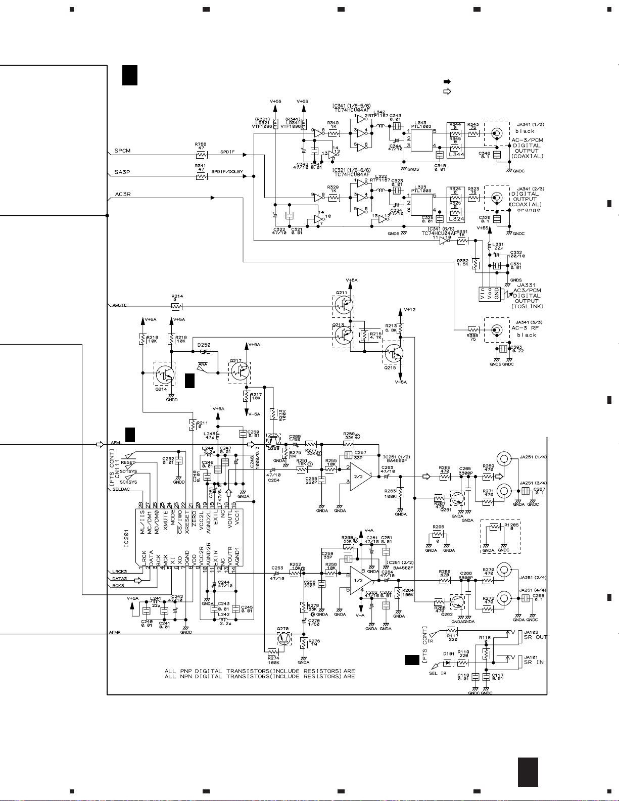
: RF SIGNAL ROUTE
: AUDIO SIGNAL ROUTE
A
1/3
J
PE8001A
TOTX178
1SS355
1/3
J
2PD601A
VKB1070
2SD2114K
B
C
2PD601A
2SD2114K
1/3
1SS355
J
PDTA124EK
PDTC124EK
5
6
7
RKN1004
J
2/3
8
D
27
 Loading...