


DRM-700
700 DISC CHANGER
CHANGEUR 700 DISQUES
DRM-7000
Operating Instructions
Mode d’emploi
300 DISC CHANGER
CHANGEUR 300 DISQUES
DRM-3000

2
<DRC1285>
En

3
<DRC1285>
En
English
The following caution label appears on your changer.
Location: rear of the changer
CAUTION
This product contains a laser diode of higher class than 1. To ensure
continued safety, do not remove any covers or attempt to gain
access to the inside of the product.
Refer all servicing to qualified personnel.
[FOR NORTH AMERICA MODELS]
CAUTION
CONSULT WITH THE COMPANY SALES REPRESENTATIVE.
“USE ONLY UL LISTED AND CANADIAN CERTIFIED POWER
SUPPLY CORD.”
A POWER SUPPLY CORD TYPE SJT, 18 AWG MINIMUM, 3WIRE GROUNDED TYPE SHALL BE USED WITH THIS
EQUIPMENT.
CLASS 1 LASER PRODUCT
LASER KLASSE 1
APPAREIL À LASER DE
CLASSE 1
WARNING:
Handling the cord on this product or cords associated with accessories sold with the product will expose you to lead, a chemical known to the State of
California and other governmental entities to cause
cancer and birth defects or other reproductive harm.
Wash hands after handling
[For Taiwanese model]
[For Korean model]
[For U.S. model]
[For U.S. model]
4
<DRC1285>
En
Thank you for buying this Pioneer product.
Please read through these operating instructions so you will
know how to operate your model properly. After you have
finished reading the instructions, put them away in a safe
place for future reference.
In some countries or regions, the shape of the power plug
and power outlet may sometimes differ from that shown in
the explanatory drawings. However, the method of
connecting and operating the unit is the same.
FEATURES..................................................5
HANDLING PRECAUTIONS ......................6
READ BEFORE USE ...................................7
Security features ................................................. 7
Offline media management ............................... 7
Deciding on system configuration ..................... 8
Add-on products ................................................. 8
Items included ................................................... 10
Discs ................................................................... 11
TO AVOID PROBLEMS ............................12
NAMES AND FUNCTIONS OF
INDIVIDUAL PARTS.................................15
INSTALLATION ........................................17
OPERATION .............................................26
User mode ......................................................... 26
System administrator mode ............................ 26
Adding drive units ............................................. 40
Exchanging drive units ..................................... 43
OTHERS....................................................46
Troubleshooting ................................................ 46
Specifications .................................................... 48
CONTENTS
IMPORTANT! SAFETY INSTRUCTIONS
1. READ INSTRUCTIONS – All the safety and operating instructions should be read before
the appliance is operated.
2. RETAIN INSTRUCTIONS – The safety and operating instructions should be retained for
future reference.
3. HEED WARNING – All warnings on the appliance and in the operating instructions
should be adhered to.
4. FOLLOW INSTRUCTIONS – All operating and use instructions should be followed.
5. CLEANING – Unplug this product from the wall outlet before cleaning.
Do not use liquid cleaners or aerosol cleaners. Use a damp cloth for cleaning.
6. WATER AND MOISTURE – Do not use this product near water.
7. ACCESSORIES – Do not place this product on an unstable cart, stand, or table.
The product may fall and be seriously damaged.
8. VENTILATION – Slots and openings in the cabinet and back or bottom are
provided for ventilation and to ensure reliable operation of the product and to
protect it from overheating. These openings must not be blocked or covered.
They should never be blocked by placing the product on a bed, sofa, rug, or other
similar surface. This product should never be placed in a built-in installation
unless proper ventilation is provided.
9. POWER SOURCES – This product should be operated only from the type of power
source indicated on the marking label. If you are not sure of the type of power
available, consult your dealer or local power company.
10. PLUG – This product is equipped with a wired grounding-type plug (a plug having a third
(grounding) pin). This plug will only fit into a grounding type power outlet. This is a
safety feature. If you are unable to insert the plug fully into the outlet, contact your
electrician to replace your obsolete outlet. Do not defeat the safety purpose of the
grounding type plug.
11. POWER-CORD PROTECTION – When unplugging the apparatus, pull on the plug – not
on the cord. Do not handle the cord on plug with wet hands. Doing so could cause an
electric short or shock. Do not allow anything to rest on the power cord. Do not locate
this product where persons will walk on the cord.
12. OVERLOADING – Do not overload wall outlets and extension cords as this can result
in fire or electric shock.
13. OBJECT AND LIQUID ENTRY – Never push objects of any kind into this product
through openings as they may touch dangerous voltage points or short out parts that
could result in a fire or electric shock. Never spill liquid of any kind on the product.
14. CONDENSATION – Moisture will form in the operating section of the product and the
product’s performance will be impaired if the product is brought from cool surroundings
into a warm room or if the room temperature rises suddenly. To prevent this, let the
product stand in its new surroundings for about an hour or two before switching it on,
or ensure that the room temperature rises gradually.
15. SERVICING – Do not attempt to service this product yourself as opening or
removing covers may expose you to dangerous voltage or other hazards.
Refer all servicing to qualified service personnel.
16. DAMAGE REQUIRING SERVICE
Unplug this product from the wall outlet and refer servicing to qualified service
personnel under the following conditions:
a. When the power cord or plug is damaged.
b. If liquid has been spilled, or objects have fallen into the video product.
c. If the product has been exposed to rain or water.
d. If the product does not operate normally when the operating instructions are
followed. Adjust only those controls that are covered by the operating instructions.
Improper adjustment of other controls may result in damage and will often
require extensive work by a qualified technician to restore the product to its
normal operation.
e. If the product has been dropped or the cabinet has been damaged.
f. When the product exhibits a distinct change in performance – this
indicates a need for service.
[For Australian and New Zealander models]
For pluggable Equipment, The Socket-Outlet Shall Be Installed
Near The Equipment and Shall Be Easily Accessible.
WARNING
This equipment is not waterproof. To prevent a fire
or shock hazard, do not place any container filed
with liquid near this equipment (such as a vase or
flower pot) or expose it to dripping, splashing, rain
or moisture.
D3-4-2-1-3_A_En
WARNING
This product equipped with a three-wire grounding
(earthed) plug - a plug that has a third (grounding)
pin. This plug only fits a grounding-type power
outlet. If you are unable to insert the plug into an
outlet, contact a licensed electrician to replace the
outlet with a properly grounded one. Do not
defeat the safety purpose of the grounding plug.
D3-4-2-1-6_A_En
Operating Environment
Operating environment temperature and humidity:
+5 ºC – +35 ºC (+41 ºF – +95 ºF); less than 85 %RH
(cooling vents not blocked)
Do not install this unit in a poorly ventilated area, or in
locations exposed to high humidity or direct sunlight (or
strong artificial light)
D3-4-2-1-7c_A_En
5
<DRC1285>
En
English
FEATURES
FLEXIBLE UNIT DESIGN
The Pioneer DRM-7000/DRM-3000-disc changer is designed
so that a variety of different components may be purchased
and installed together to meet a variety of different needs.
The Pioneer DRM-7000/DRM-3000 comes with bays (i.e.,
spaces for the installation of drives or 50-disc magazines)
located at the front and rear of the unit, and the bays are
fitted with access doors that are designed to open widely
and enable you to install or remove individual components
with ease.
The front bay is for exclusive use with 50-disc magazines;
the rear bay has been designed as a multi-purpose installation
area:
If desired, you can start with empty bay spaces and add
devices to them as your requirements increase.
THREE DIFFERENT TYPES OF DISC
MAGAZINES EQUIPPED WITH INTERNAL
MEMORY
Pioneer provides three different types of disc magazines
designed for convenience and ease of use in different
applications.
20-disc hyper magazine:
The main feature of the hyper magazine is its mobility. It
can be inserted and removed without opening the access
door. Another feature is a smart memory system that
records all user operations toward its lock/unlock
mechanism. One hyper magazine is provided as a standard
equipment with each Pioneer DRM-7000/DRM-3000.
50-disc magazine (locked-type):
This model is perfect for managing offline media where
the security and unchangeableness may be required. Builtin locking mechanism makes it impossible to remove discs
from magazine whenever it is outside the changer.
50-disc magazine (normal-type):
This model is convenient for importing or exporting large
volumes of discs into or from the changer. You can insert
discs into or remove them from a magazine releasing the
locking mechanism by a knob fitted with this magazine
when it is outside the changer.
EASE OF INSTALLATION
In order to connect the changer to an existing data
management system or to build a new data management
system, it is necessary for the host computer to be able to
properly identify the changer and all the drives contained
therein and it is necessary to attach all the cables and specify
the settings needed for the host computer to control the
changer and drives.
The Pioneer DRM-7000/DRM-3000 is designed not only to
make it easy to install and add new drives, but also with a
wide range of features designed to make it easier to specify
host computer settings.
SECURITY FEATURES DESIGNED TO
PREVENT ERRONEOUS OR
UNAUTHORIZED OPERATIONS
In order to prevent interference, conflicts, or clashes occurring
between manual operations and computer-based operations,
entering procedure to the system administrator mode is
introduced. Anyone who wants to perform operations from
the control panel is required to enter system administrator
mode first, using the provided lock release key. And it is
possible to prevent the switchover to some sub-modes by
issuing a command from the host computer.
It is also possible to assign security privileges on the system
administrator who has the lock release key. Then operations
directly manipulating discs, like opening mailslot and ejecting
hyper magazine, are permitted to only the system
administrator.
CONTROL PANEL FITTED WITH AN LCD
MESSAGE WINDOW FOR EASE OF USE
The control panel is fitted with a 2-line, 16-column LCD
message window which is used to display instructions on
the proper operations to perform. And this makes it possible
to perform any of the wide variety of different operations
provided by the DRM-7000/DRM-3000 with only 5 keys.
Loading Capacity
DRM-7000 DRM-3000
Front bay
50-disc magazines only 7 3
Rear bay
Component Max 16 Max 8
50-disc magazines Max 7 Max 3
The maximum number of optional components that can be
installed differs depending on the component involved; for
details, consult the operating instructions for your option
components.
Combined Example
DRM-7000 DRM-3000
Data capacity emphasis Drives 2 Drives 2
Discs 720 Discs 320
Performance emphasis Drives 16 Drives 8
Discs 370 Discs 170

6
<DRC1285>
En
HANDLING PRECAUTIONS
FOR SAFETY
÷ Do not install the unit on any unsteady platform or desk,
etc., as the unit is tall and heavy.
÷ Do not stack the units or do not place a heavy object on
the unit. It is extremely dangerous to do this, because the
objects may fall off or the unit may topple over. (Any
damage or injury suffered as a result of such installation is
the sole responsibility of the user. )
÷ Attach the placement fixtures first after unpacking the
changer. If it is moved before they are attached, there
is a danger of it toppling over or of the cables on the
rear being damaged.
÷ Always be sure not to insert your hand into the 20-
disc hyper magazine bay or not to touch any parts
inside of the bay when the power has been turned on,
otherwise it may result in bodily injury.
÷ For safety reasons, the DRM-7000/DRM-3000 is designed
so that the access doors cannot be opened while the
changer mechanism or internal drives are in operation.
÷ The high speed rotation of discs or the operation of the
high speed disc transport mechanism in the DRM-7000/
DRM-3000 causes slight vibrations and noise, but this does
not indicate a problem. And it does not effect the
performance of the changer.
CONDENSATION
If the temperature difference between the changer and
environment is too large, water will condense in the changer
and the system may not provide proper performance. For
example, if you bring the changer into a warm room from
outside in cold weather, or if you increase room temperature
abruptly, condensation may result. If condensation occurs,
leave the changer for one hour in the room, or increase room
temperature gradually before using it.
CLEANING THE CHANGER
To clean the panel and the cover, use a soft, dry cloth to wipe
off dust and dirt. If the cabinet is heavily soiled, wipe off the
dirt using a soft cloth soaked with neutral detergent diluted 5
to 6 times. Then wipe the water off with a dry cloth. Do not
use benzine, thinner, insecticide or similar volatile chemicals,
as they may dissolve or discolor the cabinet surface. If you
use a chemical polishing cloth, carefully read the instructions
supplied with it.
INSTALLATION
Select an installation site with a flat, solid surface.
Do not install the system where it will suffer any of the
following:
1 Exposure to direct sunlight or a heater
2 High humidity or dust
3 Proximity to bathroom or kitchen
4 Exposure to spotlight
5 Proximity to any large electric apparatus such as a
refrigerator, air conditioner, dimmer, etc.
6 Uneven or unsteady installation surface.
(If the surface is not flat, first put down a hard plate or
similar support so that the system is installed level.)
7 Difficulty of service and maintenance.
If the changer is to be installed next to a wall, a minimum of
at least 50 cm of space must be provided between the back
of the changer and the wall.
Avoid placing objects directly on the changer.
HANDLING PRECAUTIONS
÷ Be careful not to stain, scratch or leave fingerprint, etc.,
on the signal surface, or recording surface of the discs.
The specified playback performance or recording
performance may not be obtained with such discs.
÷ Do not insert more than one disc in a mailslot, otherwise
malfunction will result.
÷ The Changer does not manage the disc contents. The data
should be managed by involving the host.
÷ Use only recording discs recommended by Pioneer. The
specified recording performance or playback performance
may not be obtained if a non-recommended disc is used.
Please note that the data recorded on discs is not covered
by our warranty.
÷ Pioneer may not be held liable for the loss of any data or
any other direct or indirect damage suffered as the result
of the use or breakdown of this product. It is strongly
recommended that regular backups be taken of all critical
data.
÷ Please be careful not to lose the lock release keys provided
with your DRM-7000/DRM-3000, otherwise you could not
manage your changer any more. The lock release key
certifies you as a system administrator and gives you a
privilege to open access doors, to eject a hyper magazine
and to use a mailslot.
POWER-CORD CAUTION
Handle the power cord by the plug. Do not pull out the plug
by tugging the cord and never touch the power cord when
your hands are wet as this could cause a short circuit or an
electric shock. Do not place the unit, a piece of furniture,
etc., on the power cord, or pinch the cord. Never make a
knot in the cord or tie it with other cords. The power cords
should be routed such that they are not likely to be stepped
on. A damaged power cord can cause a fire or give you an
electrical shock. Check the power cord once in a while. When
you find it damaged, ask your nearest PIONEER authorized
service center or your dealer for a replacement.

7
<DRC1285>
En
English
READ BEFORE USE
SECURITY FEATURES
Information on the location of discs within the changer and
information to access data on discs are strictly monitored
and controlled from the changer control software and the
upper-level database management software.
Because of this, if any changes in the status of the discs
within the changer occur at a time when the changer is not
under the control of the host computer (or in a network
environment, under the control of a server), it becomes
impossible to control the changer and drives and to read
necessary files from discs.
Allowing discs stored within the changer to be removed
without any restrictions poses a security risk, not only in that
it would become impossible to access discs which have been
removed but also in that it might lead to the damage or loss
of discs.
Although the DRM-7000/DRM-3000 has been designed so
as to open the front and rear access doors from the control
panel (located at the top of the front of the unit) to remove
magazines or to insert or remove discs through the mailslots,
anyone who considers the security issues noted above will
be able to understood that it is necessary to place restrictions
on such operations.
This is why the control panel of the DRM-7000/DRM-3000
has been fitted with a key switch which may be locked to
disable operations of control keys. This switch cannot be
unlocked without the key provided with the DRM-7000/DRM3000, and if the system administrator will always keep this
key, it is impossible that ordinary users without key perform
unauthorized operations from the control panel.
It is also possible to restrict the range of operations which
are performed from the control panel. It means that a part of
system administrator’s privileges is controlled by the
command issued from the host computer and even if a
system administrator has the key, the host computer makes
it impossible to open the access doors, exchange discs, or
perform other unfavorable operations for itself.
OFFLINE MEDIA MANAGEMENT
The DRM-7000/DRM-3000 provides the following features
which makes it perfect for the management of offline media.
¶ Removable disc magazines
Disc magazines may be removed from the changer with
the discs left in the magazines. The use efficiency of the
space within the changer may much improve if the
infrequently used discs are collected in one magazine and
it is taken out from the changer into the offline storage.
¶ Unique disc magazine IDs
All disc magazines used in the DRM-7000/DRM-3000 are
assigned unique ID codes which makes it possible to
identify individual magazines simply by inserting them into
the magazine bays.
All of the discs within an inserted magazine become
available immediately no matter which magazine bay it is
inserted into as long as the discs installed in the magazine
have been registered in the database as corresponding to
the magazine ID in question, and the same holds true when
a magazine is inserted into a different changer as long as
the changer in which it is inserted is under the control of
the same database.
¶ Disc magazines designed for easy tracking and control
Removing, inserting or replacing discs in magazines after
they have been removed from a changer may destroy the
correspondence between discs and magazine IDs.
To solve this problem, Pioneer provides 50-disc magazine
which has a locking mechanism to prevent all attempt to
change the status of the magazine outside the changer
and hyper magazine which has a smart memory system
that records all user operations toward its lock/unlock
mechanism so as to make it easier to track and control
the use of offline media.
¶ Registration of changer ID
When a disc magazine has been inserted into a changer
not under the control of the database management
software or into a changer belonging to another system,
the discs within that magazine may be rewritten or may
be replaced with other discs within that changer. Even if
the magazine in question is a locked-type, these
discrepancies between the discs actually contained within
the magazine and the information on those discs stored in
the database may be arise.
In order to prevent such problems from occurring, disc
magazines are designed to record the ID of the changer in
which they are used, and as long as the database has a
list of the IDs of changers controlled under the given
database, it is possible for the database management
software to determine whether or not a inserted disc
magazine has to be reinstalled by checking the changer
ID that may be read with the magazine ID.
However although the DRM-7000/DRM-3000 changer and
disc magazines do provide the features needed for the
management of offline media, it should be noted that the
actual procedures and methods available for the management
of offline media may differ depending on the database
management software and changer control software being
used.
It should further be noted that it is necessary to establish
how to employ controls for the handling of offline media. In
fact if management controls are strict enough, it is even
possible to use normal-type disc magazines which would
ordinarily be unsuited for use in the management of offline
media, in the same way as one would use locked-type disc
magazines.

8
<DRC1285>
En
Read before use
DECIDING ON SYSTEM
CONFIGURATION
Before installing or using the changer, the first thing which
has to be done is to decide what components you should
install to where of the changer.
The connector panel and SCSI cables which come with the
DRM-7000/DRM-3000 are prepared on the assumption of the
following system configuration:
7 Two SE drives.
7 The two SE drives to be internally daisy-chained, and
connected to the changer using the accessory SE SCSI
cable.
(This type of configuration requires an additional SE SCSI cable
for connection to the SE SCSI host adapter.)
In the event that three or more SE drives are to be used, the
changer is to be connected to an LVD host adapter, an LVD
drive is to be installed, or in cases when multiple SCSI buses
are to be used to increase data transmission speed, optional
devices will be necessary in accordance with the specific
configuration planned.
To determine what additional equipment must be purchased
in order to create a desired configuration, it is recommended
that you first decide where drives are to be installed and
consult the configuration sheet on p. 188 (DRM-7000) or p.
189 (DRM-3000) before actually trying to configure your
system.
Before actually beginning to configure your changer system,
it is absolutely necessary that the following items be
determined:
¶ Type, number, and install position of drives
The DRM-7000/3000 uses an SE SCSI interface. When
the changer is connected to an LVD SCSI host adapter, or
when a DVD-R7783 using an LVD SCSI interface is installed
on the same bus as the changer, it is necessary to install
an LVD SCSI interface unit (DRM-ULV16).
Also, an additional power unit is required when nine or
more drives are to be installed on a single DRM-7000
changer.
¶ Type and install position of connector panel
Different connector panels are available for use with LVD
drives (internal daisy-chain connection) and SE drives
(internal daisy-chain connection and direct drive
connection).
¶ Cable connection method from connector panel to each
drive
¶ SCSI ID assignment
Multiple drives on the same SCSI bus must not have
identical ID.
¶ SCSI terminator setting
<SE SCSI bus>
The terminating switch for the drive or changer at the end
of the SCSI bus should be set to ON.
<LVD SCSI bus>
When DVD-R7783 and DRM-ULV16 are installed, it is
necessary to terminate the LVD SCSI bus.
Since the DVD-R7783 is not provided with a SCSI
terminator, an optional terminator must be purchased, or
the attached SCSI terminator (LVD) of DRM-ULV16 should
be used to provide LVD SCSI bus termination.
For SCSI connection refer to the “SCSI Connection Manual”
or consult your dealer.
ADD-ON PRODUCTS
The following components may be purchased separately for
use with the Pioneer DRM-7000/DRM-3000 in order to adapt
it for use in configuring a system to your own specifications.
The maximum number of optional components that can be
installed differs depending on the component involved; for
details, consult the operating instructions for your option
components.
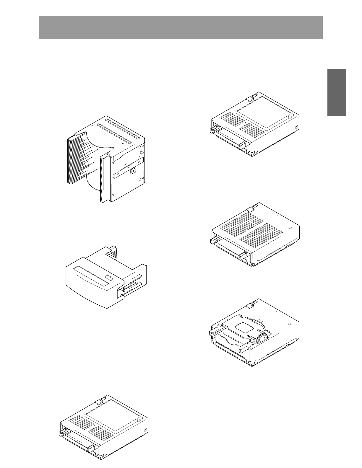
50-disc magazine
Used to store discs within the changer, these magazines
come in both normal and locked types which can be installed
in whatever combination best fits your needs.
¶ 50-disc magazine (locked-type)
[DRM-AL751]
The power unit provided as standard equipment is capable
of supplying power to rear bays #1 – 8. The total power
consumed by these eight drives should not exceed the
following:
DC +5 V 12 A or less
DC +12 V 8 A or less
The maximum current capacity of a single connector is as
follows:
DC +5 V Max 4 A
DC +12 V Max 4 A
By adding an optional expansion power unit to the DRM7000, power can be supplied to rear bays #9 – 16.
The maximum power consumption of these upper bays
and the maximum amount of power which may be supplied
over a single connector is the same as that of the lower
bays (i.e., Bay #1 – Bay #8).
NOTE:
Be sure never to use any add-on products other than
Pioneer products.
When turning off the power and turning it back on,
always be sure to allow an interval of 10 seconds or
more to elapse after turning off the power before turning
it back on. Note that this must be done because there
are times when the power is not switched off
immediately even after the power switched has been
flipped off when few drives have been installed in the
changer.
9
<DRC1285>
En
English
Read before use
These disc magazines are designed so that the lock is not
released even when a magazine is removed from a
changer. Therefore the mailslot is necessary to insert discs
into these magazines or remove discs from them. These
magazines are extremely effective for use in situations
where they are used in combination with a host computer
which supports offline media management. (See p. 7 for
further details.)
¶ 50-disc magazine (normal-type)
[DRM-AF751]
Fitted with a knob which is used to release the locking
mechanism, these magazines are convenient for importing
or exporting large volumes of discs into or from the
changer.
20-disc hyper magazine [DRM-AH721]
This magazine is designed to make it possible to insert or
remove without opening the access doors. This magazine is
also equipped with a smart memory system that records all
user operations toward its lock/unlock mechanism. Therefore
the hyper magazine is convenient and also perfect for the
management of offline media. The DRM-7000/DRM-3000
comes with a hyper magazine as a standard equipment, and
additional hyper magazines may be used to easily build up an
offline library in 20-disc units.
DVD-R/RW drive unit [DVD-R7322]
Power consumption: DC +5V, 1.5A
DC +12V, 1.0A
This is an SE SCSI interface drive for reading DVD-ROM discs
and for reading/writing DVD-R/RW discs.
DVD-ROM drive unit [DVD-D7563]
Power consumption: DC +5V, 1.0A
DC +12V, 1.0A
This is an SE SCSI interface drive for reading DVD-ROM discs
and DVD-R/RW discs.
Disc flip unit [DRM-UF701]
The DRM-UF701 disc flip unit is designed for use in turning
over a disc. Note that this component is required when using
double-sided DVD discs.
DVD-R/RW drive unit [DVD-R7783]
Power consumption: DC +5V, 1.5A
DC +12V, 1.0A
This is an LVD SCSI interface drive for reading DVD-ROM
discs and for reading/writing DVD-R/RW discs.
Power supply unit [DRM-PW701] (for DRM-7000)
A DRM-PW701 add-on power supply unit must be installed
in order to use 9 or more drives within the same changer.
Always be sure to contact Pioneer service personnel for
installation.
Power supply: Maximum of DC +5V, 12A
Maximum of DC +12V, 8A

10
<DRC1285>
En
Read before use
ITEMS INCLUDED
20-disc hyper magazine ... 1
SCSI cable (SE) for connecting changer
and drive ...1, 0.35 m
Power cord (for Japan) ... 1
Power cord (for Canada and the U.S.) ... 1
Base stabilizer
DRM-7000: 4 DRM-3000: 2
This type of power cord is for use
in America and Canada only.
Do not use this power cord in places
other than America or Canada.
This type of power cord is for use
in Japan only.
Do not use this power cord in a
places other than Japan.
LVD SCSI interface unit [DRM-ULV16]
This unit is necessary when connecting the DRM-7000/3000
with SE SCSI interface to an LVD host adapter. Always be
sure to contact Pioneer service personnel for installation.
LVD drive connector panel (for 2 drives)
[DRM-LN721]
This connector panel is provided with a cable allowing two
LVD drives to be daisy-chained inside the changer.
LVD drive connector panel (for 4 drives)
[DRM-LN741]
This connector panel is provided with a cable allowing four
LVD drives to be daisy-chained inside the changer.
SCSI terminator (LVD) [DRM-TM160]
This is an externally mounted LVD terminator.
Since the DVD-R7783 is not provided with an LVD SCSI
terminator, termination must be provided for either with the
use of this unit, or else with the SCSI terminator (LVD)
provided with the DRM-ULV16.
SCSI cable (LVD)
[CC-200]
2.5 m, VHDCI 68-pin to Half-pitch 68-pin
[CC-200-8]
8 m, VHDCI 68-pin to Half-pitch 68-pin
[CC-201]
2.5 m, Half-pitch 68-pin to Half-pitch 68-pin
[CC-201-8]
8 m, Half-pitch 68-pin to Half-pitch 68-pin
These are LVD SCSI cables for use with external cabling, to
be used between host adapter and changer, or when daisychaining changers. Select the proper length and connector
configuration for your system.
Multi drive connector panel [DRM-SN721]
This connector panel is provided with a cable allowing two
SE drives to be daisy-chained inside the changer. One panel
is provided as standard equipment, and it can be combined
with “Cable for 2 drives” and “Cable for 4 drives.”
Single drive connector panel [DRM-SN711]
This connector panel can be used for direct connection of an
SE drive to SE SCSI host adapter, or for external daisy chain
connection.
Cable for 2 drives [DRM-SC721]
This is an SCSI cable supporting the expanded daisy-chain
installation of up to two SE drives. When combined with the
Multi drive connector panel, four SE drives can be daisychained inside the changer.
Cable for 4 drives [DRM-SC741]
This is an SCSI cable supporting the expanded daisy-chain
installation of up to four SE drives. When combined with the
Multi drive connector panel, six SE drives can be daisy-chained
inside the changer.
* Installed in the changer body
11
<DRC1285>
En
English
Read before use
DISCS
Discs which may be used with the Pioneer DRM7000/DRM-3000
The types of discs which may be used with the Pioneer DRM7000/DRM-3000 vary depending on the types of drives being
used, and for further information on the types of discs which
may be used you should accordingly consult the operating
instructions provided with your drive units.
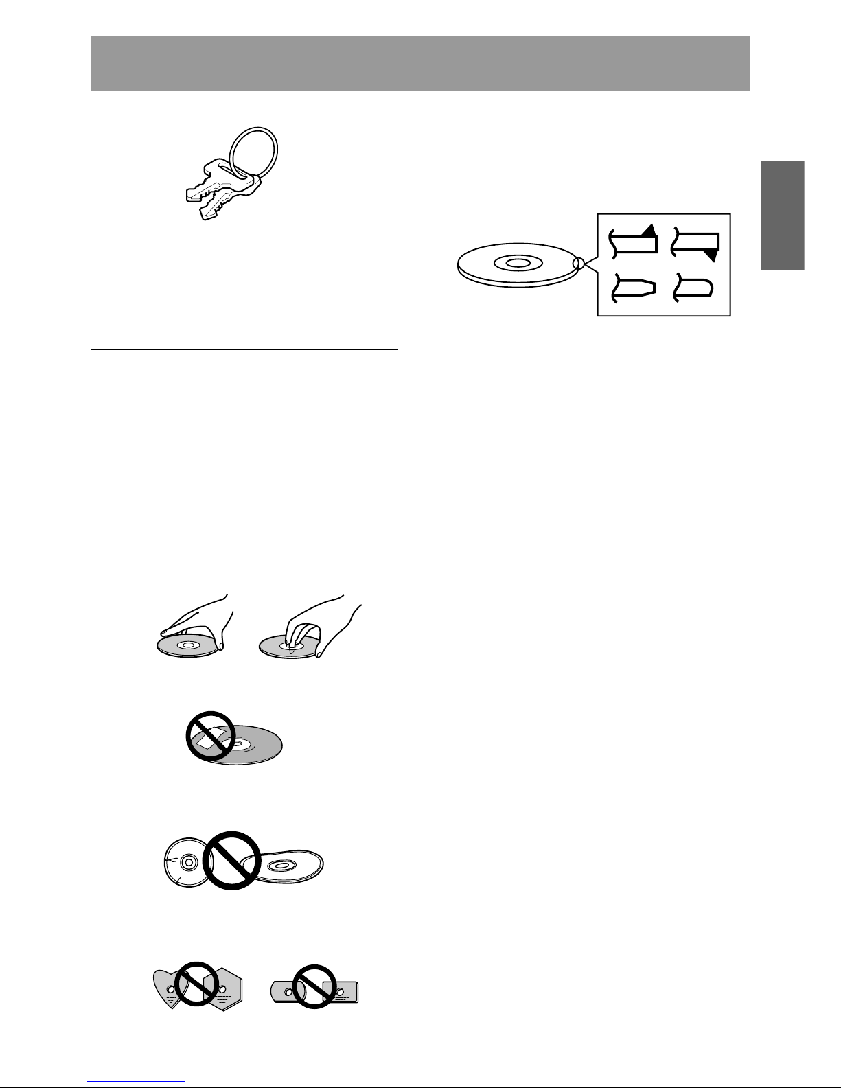
Handling the discs
÷ Avoid touching the signal surface when you use a disc.
÷ To hold it, place your fingers on the edge of the disc or the
edge of the center hole and the disc edge.
÷ Do not use the following types of discs for they may cause
malfunction of the unit or damage to the discs:
÷ Disc which has a molding flash (projected fin) left on
the periphery as shown in the figure.
÷ Disc with its edges are rounded or tapered as shown in
the figure.
÷ Do not attach paper or stickers to the label side of the
disc. Handle discs carefully and avoid damaging the label.
÷ Discs rotate at high speed in the changer. Do not use
defective discs (e.g., cracked or considerably warped).
Such discs may damage the changer.
÷ DO NOT use non-standard discs, as these may adversely
influence this unit and other equipment.
÷ DO NOT play a disc having other shape than a circular
disc, such as heart shaped disc, or malfunction may occur.
Lock release key ... 2
Screw for use in attaching base stabilizers
DRM-7000 ... 12
DRM-3000 ... 6
Operating instructions ... 1
÷ Discs with adhesive surface on periphery or label face.
÷ When discs are handled within a dry environment, the discs
themselves may become charged with static electricity.
Handle discs only after touching a metal fixture or
otherwise discharging any static electricity from your body.
÷ Do not place discs in locations where they may be exposed
to dust or static electricity.
÷ The Changer can accommodate only the discs with a
diameter of 12 cm (5 in). As the Changer detects the
presence of disc with optical detection of the position at
about 5 mm (3/16 in) inside the external periphery of the
12 cm (5 in) disc, the use of a disc which is transparent at
the corresponding position (*) or a 8 cm (3 in) disc may
lead to disc detection error and to the disc damage in the
worst case. Also, the use of a 8 cm disc adapter is strictly
prohibited.
* Includes translucent “C-thru Disc” discs.
÷ This unit does not support “DualDisc (The Hybrid CD/DVD
Disc)”.

12
<DRC1285>
En
1. Installation
2. Connections
3. Power ON/OFF
4. Control
5. Transporting Unit
6. Error Correction
÷ Do not place foreign objects inside the changer, since malfunction
may result.
÷ Do not use the changer in locations subject to high concentrations
of dust, heat, or humidity.
* Do not install in locations directly exposed to outdoor dust or air.
* Do not install near air conditioner vents or air cleaners.
÷ Do not subject the recorder to impact or vibration during use.
* Do not install in hallways or other areas near frequent pedestrian
traffic.
÷ When connecting exterior SCSI cable, be sure that power is first
turned off to host computer and changer.
* When connecting internal SCSI cable, power may be left while
connecting.
÷ When installing a drive, be sure to connect the changer interface
cable to the connector corresponding to the bay in which the drive
is installed. If the cable is mistakenly connected to a neighboring
connector, the discs may be damaged and the E99 error may occur.
÷ The final device on a SCSI bus must have its terminator switched
ON, or an external terminator device used. The changer may operate erratically if proper termination is not provided. If no termination
is used and malfunctions occur, turn termination on before restoring
power to the changer.
* If the final device on a SCSI bus (with terminator turned ON) is
removed from the bus, or if its SCSI cable is disconnected, it means
that bus termination is not provided from that time, and the same
kind of malfunctions may occur as described above.
÷ When installing a drive, if the wiring monitor indicator does not flash,
recheck and install the power cable connection, followed by the
changer interface connection.
÷ Never disconnect power while the changer is transporting a disc, or
when the writer is recording data to a disc.
÷ When turning the power off and then on again, wait at least ten
seconds after turning the power off before turning it on again.
÷ During data recording, do not send commands from the disc writer
to remove disc (Move Medium, Rezero Unit), since EC❋ error or
write malfunction may occur (back buffer underrun).
÷ When transporting the unit, pack the unit in its original packaging
materials, and ship in an upright position. Do not transport the unit
on its side.
÷ Do not transport the unit with drive units, 50-disc magazines or other
optional accessories loaded (except for 20-disc hyper-magazine).
When transporting the accessories, repack them in their original
packaging materials.
÷ Do not transport disc magazines with discs loaded.
÷ E8❋, E9❋, EF8, or EF3 errors cannot be corrected merely by reset-
ting the changer’s power on/off. The system administrator mode
must be used to open and then close the door again. For these and
other errors, see the Operating Instructions, p. 46.
÷ [E83], [E99], [E88]
÷ Recording/playback mal-
function
÷ Recording/playback mal-
function
÷ Changer malfunction
÷ [E83], [E99]
÷ Display window (LCD)
doesn't appear correctly.
÷ Operation keys malfunc-
tion.
÷ Changer not recognized
on the SCSI.
÷ Changer does not detect
drive.
÷ Changer malfunction.
÷ Data recording malfunc-
tion
÷ Recording malfunction
÷ [EC❋], (where ❋ = 0 – F)
÷ [E8❋], [E9❋], [EF8], [EF3]
(where ❋ = 0 – F)
TO AVOID PROBLEMS
The following is a list of operation items that may potentially lead to problems in component functioning.
Potential Malfunction/ErrorIssue

13
<DRC1285>
En
English
7. Discs
8. Disc Magazines
9. Loading discs
10. Disc flip Unit
÷ Blank discs, discs which have experienced failed recording opera-
tions, and discs whose recording sessions have not been closed,
cannot be used on the reader drive.
* Use the writer drive to determine whether a disc is blank.
÷ Do not affix paper labels or seals to discs. Also, do not allow the
printed surface of discs to become scratched.
* If a paper label is removed incorrectly, it may leave behind pieces
of adhesive that cause player malfunction; as a result, when re
moving an adhesive label, be sure to remove it carefully and fully,
taking care not to leave an scratches on the surface of the disc.
÷ Scratches, fingerprints, or dirt adhering to the surface of a disc may
interfere with recording or playback. When handling discs, take care
not to touch the signal surface (the reflective recording surface).
Hold discs either by the outside edges, or by placing a finger in the
center hole.
÷ If a disc is soiled, wipe gently with a soft cloth in a radial direction,
straight from the center outwards. Do not wipe in a circular pattern.
* Use only the Pioneer Cleaning Cloth (Service Parts GED-009) for
wiping discs.
÷ To produce stable recording and playback, use only recommended
discs. For recommended discs, consult your dealer or Pioneer's
website.
÷ This component does not support DVD-R for Authoring media.
÷ When inserting discs in magazines, be sure they are inserted flat
into the same slot; discs may be damaged if inserted diagonally (with
left and right edges in differing slots).
÷ Do not allow the open end of magazines to point downward, since
discs may fall out.
÷ Insert magazines slowly into the changer, since discs may fly fall out
if the magazine is inserted with excessive force.
* When inserting a magazine, if the electronic buzzer sounds or
error [E83 disc set NG] appears in the display, remove the magazine, press any dislodged discs back into the magazine, and slowly
insert the magazine once again.
÷ When loading discs in the disc magazine or hyper-magazine, we
recommend the use of the mail slot to prevent insertion mistakes.
* When setting a disc on the mail slot tray, place it gently so it does
not protrude from the tray.
÷ When the Pioneer Disc flip unit DRM-UF701 is used in conjunction
with the changer DRM-7000, the changer must be equipped with
firmware Rev. 1.12 or later. Since malfunctions or disc damage may
occur when used with firmware revisions earlier than 1.12, be sure
to update your firmware to Rev. 1.12 or later before use.
For details regarding updating of firmware, consult your Pioneer
service center, or retail dealer.
* The DRM-3000 module is not limited by firmware revisions.
÷ Reader drive malfunction
÷ [Set Up NG] error
÷ Recording/playback mal-
function
÷ [E83], [E99]
÷ Recording/playback mal-
function
÷ Recording/playback mal-
function
÷ Recording/playback mal-
function
÷ Cannot record
÷ [E83], [E99]
÷ [E83]
÷ [E83]
÷ [EC❋], (where ❋ = 0 – F)
÷ Other malfunctions
TO AVOID PROBLEMS
Potential Malfunction/ErrorIssue

14
<DRC1285>
En
11. DVD-R/RW drive
unit DVD-R7783
12. LVD SCSI
interface unit
DRM-ULV16
÷ In order to allow use of the DVD-R7783, changer firmware revision
must be 1.25 or later (for either DRM-7000 or DRM-3000).
If a firmware revision earlier than 1.25 is used, the changer’s device
driver may not operate correctly. Be sure to update your firmware to
Rev. 1.25 or later before use.
For details regarding updating of firmware, consult your Pioneer
service center, or retail dealer.
÷ When the DVD-R7783 is installed, the Power supply unit DRM-
PW701 cannot be used.
÷ When using the DRM-ULV16, the SE SCSI bus must be limited to
the following conditions. Usage is not supported beyond these limits:
Total bus length including internal to device: 3 m or less
Number of drives connected on bus: 3 or less *
* Under these conditions, a maximum of 3 SE drives can be
installed on a single changer. In addition, due to the limitations on
cable length, drives should be installed in the rear bays #1 to #3.
÷ When the DRM-ULV16 is installed, the Power supply unit DRM-
PW701 cannot be used.
÷ Changer’s device driver
malfunctions
÷ Disc write/playback error
÷ Disc write/playback error
÷ SCSI transmission error
÷ Disc write/playback error
TO AVOID PROBLEMS
Potential Malfunction/ErrorIssue
15
<DRC1285>
En
English
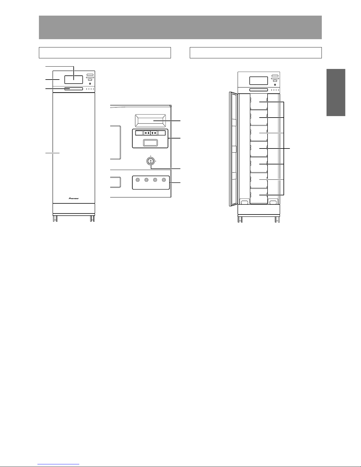
NAMES AND FUNCTIONS OF INDIVIDUAL PARTS
FRONT
1 20-disc hyper magazine
2 Control panel
3 Mailslot
4 Front access door
5 LCD message window
The backlight to the LCD message window is designed to
automatically go into energy saving mode whenever more
than 1 minute passes without any operations being
performed from the control panel.
6 Operation keys
These keys are used to change the display items on the
LCD message window and to select setting fields or
values. Note that a lock release key is required in order to
become effective these keys.
Escape key (ESC):
The escape key is used to step back from the message
layer currently being displayed (i.e., to return to the
previous display) or to halt operations.
|«:
This key is used to decrement displayed values or to
move the display cursor down or to the left.
»\:
This key is used to increment displayed values or to
move the display cursor up or to the right.
Enter key (ENT):
The enter key is used to step forward from the message
layer currently being displayed or to initiate a specified
operation.
<Control panel>
FRONT ACCESS DOOR INSIDE
1
2
3
4
ESC ENT
FUNCTION
LOCK
POWER
UNLOCK
ROBOTICS
BUSY
DRIVE
BUSY
MAILSLOT
OCCUPIED
5
6
7
8
9
Function key (FUNCTION):
The function key must be pressed in order to enter the
system administrator mode.
7 Lock/Unlock key switch
Inserting a lock release key into this switch and rotating it
90 degrees releases the operation lock and makes it
possible to perform operations from the control panel.
8 Status indicators
POWER:
This indicator lights up whenever the power is on.
ROBOTICS BUSY:
This indicator lights up whenever a disc transport
mechanism is in operation.
DRIVE BUSY:
This indicator lights up whenever one or more discs
are being placed on each drives.
MAILSLOT OCCUPIED:
This indicator lights up whenever a disc is placed in the
closed mailslot.
9 Front bays
DRM-7000
For use with disc magazines: M1 – M7
DRM-3000
For use with disc magazines: M1 – M3
16
<DRC1285>
En
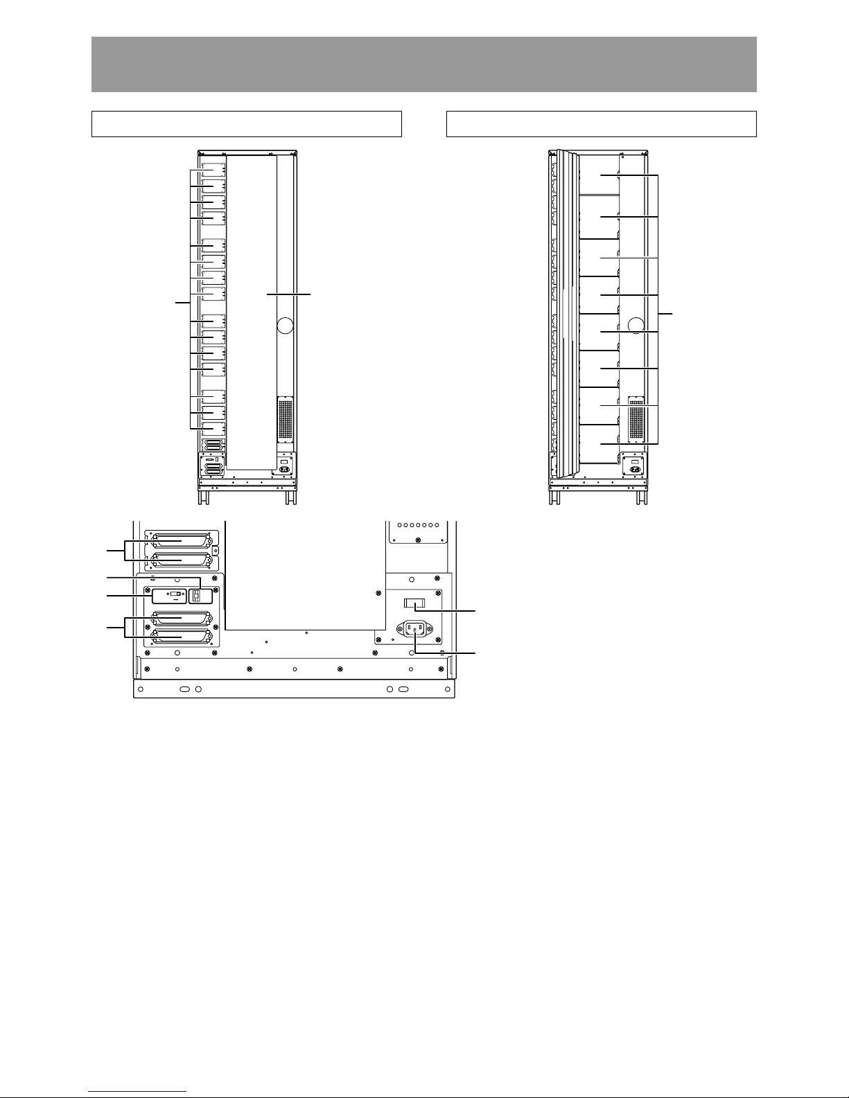
REAR
1 Rear plates
These plates cover the space for attaching the connector
panels.
2 Rear access door
3 SE drive SCSI ports (attached connector panel)
4 SCSI ID switch (ID)
This switch is used to assign the changer SCSI ID. If you
would like to decrement the displayed SCSI ID, push the
small switch just above the numeric display by a nib. And
if you would like to increment, push the small switch just
below the numeric display. Note that SCSI ID is set to ‘6’
at the time of shipment.
5 SCSI termination switch (TERM)
This switch is for SCSI termination. Note that this switch
is set ON at the time of shipment and it must be kept ON
during the changer installation. But when the SCSI bus
connection is completed and the changer is not the last
device on the SCSI bus, it must be set OFF certainly.
REAR ACCESS DOOR INSIDE
Names and functions of individual parts
1
2
TERM
OFF ON
ID
C H A N G E R S C S I
ONOFF
GND
POWER
A C I N
7
8
3
6
5
4
9
6 Changer SCSI ports (CHANGER SCSI)
7 Power switch (POWER)
This switch is used to turn the power to the changer on
and off.
8 Power inlet (AC IN)
The power cord is inserted into this power inlet. (Note
that you should always be sure to use only the power cord
provided with your changer.)
9 Rear bays
DRM-7000
For use with disc magazines: M8 – M15
For use with optional units/modules: Bays #1 – 16
DRM-3000
For use with disc magazines: M4 – M7
For use with optional units/modules: Bays #1 – 8
17
<DRC1285>
En
English
INSTALLATION
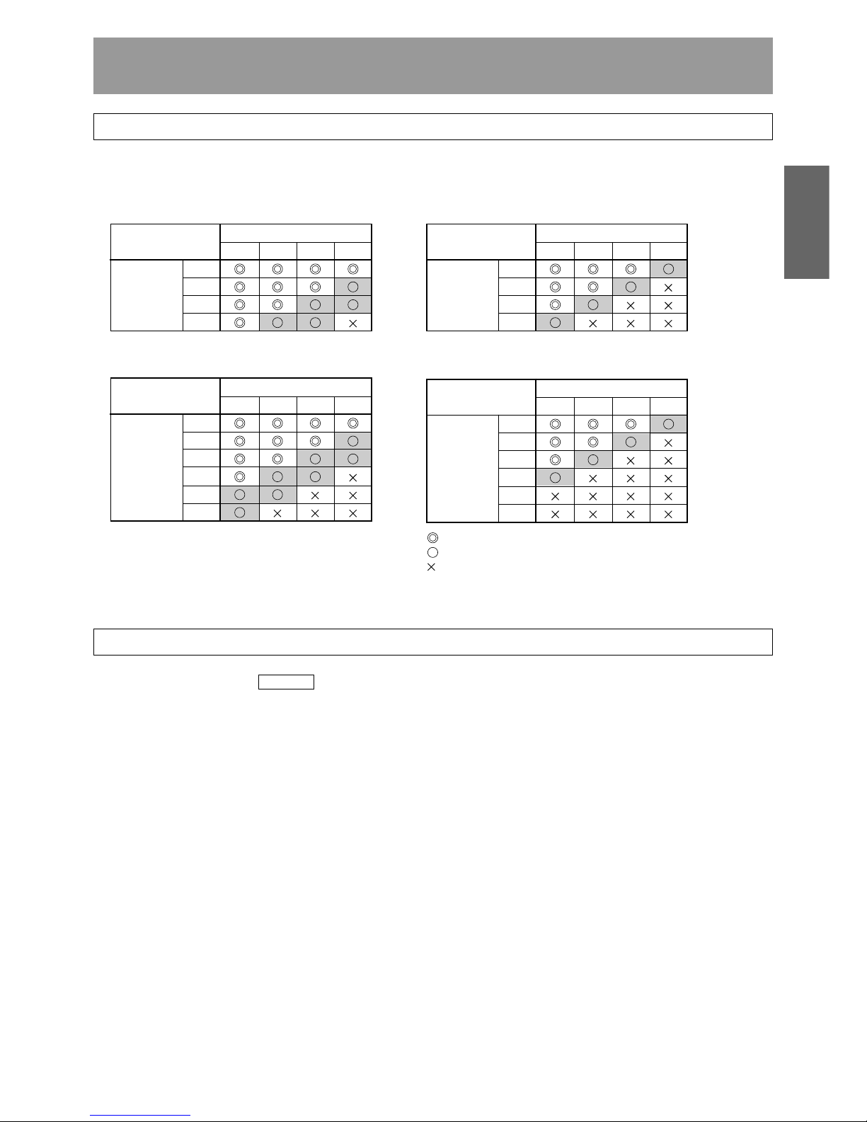
REGARDING MAXIMUM DRIVES WHEN USING DVD-R7783
In order to assure optimum drive performance, please adhere to the following configuration and environment parameter:
÷ When DRM-ULV16 is installed, and DVD-R7783 is connected on same bus as DVD-D7563 or changer
(see page 18, examples 1 – 3)
÷ When DRM-ULV16 is not installed, and DVD-R7783 is connected to separate bus from DVD-D7563 or
changer (see page 18, examples 4, 5)
: Within room temperature limits of 5°C to 35°C.
: Within room temperature limits of 5°C to 30°C.
: This configuration not supported.
* The above figures indicate the number of drives permissible for each changer.
LIMITATIONS WITH SCSI CONNECTIONS
* For further details, consult “ STEP 2 4. Connecting SCSI cables ” (page 21).
A. When installing DRM-ULV16
(When LVD SCSI bus and SE SCSI bus are the same; see page 18, examples 1-3).
7 Connection Cable Length
LVD SCSI bus: 12 m or less
This is the total permissible length of cable, including that internal to devices (when multiple changers are connected,
includes length of cable between changers).
SE SCSI bus: 3 m or less
This is the total permissible cable for each changer, including internal cables.
7 Permissible SE drives: Maximum 3 (for each changer)
* Due to limitations on cable length, SE drives should be installed in rear bays #1 to #3.
B. When not installing DRM-ULV16
(When LVD SCSI bus is separate from SE SCSI bus, or SE SCSI bus alone is used; see page 18, examples 4-6)
7 Connection Cable Length (for each host adapter)
LVD SCSI bus: 12 m or less
This is the total permissible length of cable, including that internal to devices (when multiple changers are connected,
includes length of cable between changers).
SE SCSI bus: 6 m or less*
This is the total permissible length of cable, including that internal to devices (when multiple changers are connected,
includes length of cable between changers).
*SCSI-2 mode
DVD-R7783
1234
0
1
2
3
DRM-7000
DVD-D7563
DVD-R7783
1234
0
1
2
3
4
5
DRM-7000
DVD-D7563
DVD-R7783
1234
0
1
2
3
DRM-3000
DVD-D7563
DVD-R7783
1234
0
1
2
3
4
5
DRM-3000
DVD-D7563
18
<DRC1285>
En
Installation
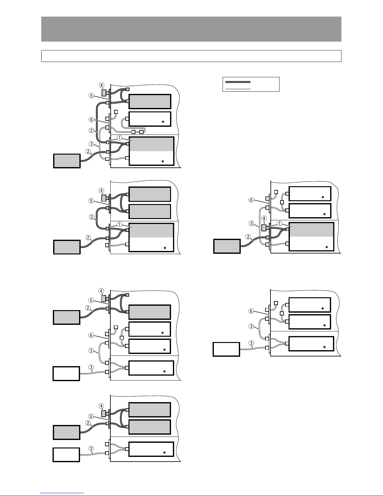
SCSI CABLE CONNECTION EXAMPLES
A.When installing DRM-ULV16
LVD Line
SE Line
1 DRM-ULV16
2 SCSI cable (LVD)
3 SCSI cable (SE)
4 SCSI terminator (LVD)
5 LVD drive connector panel (for 2 drives)
6 Multi drive connector panel
* SE device SCSI terminator switch setting
[Example 1]
Host
LVD Drive 1
SE Drive 1
DRM-ULV16 Board
Changer Board
(OFF)
(ON)
(LVD)
[Example 2] [Example 3]
LVD Drive 1
LVD Drive 2
DRM-ULV16 Board
Changer Board
(ON)
Host
(LVD)
DRM-ULV16 Board
SE Drive 2
SE Drive 1
Changer Board
(OFF)
(OFF)
(ON)
Host
(LVD)
B. When not installing DRM-ULV16
[Example 4]
[Example 6]
LVD Drive 1
SE Drive 2
SE Drive 1
Changer Board
(OFF)
(OFF)
(ON)
Host 2
(LVD)
Host 1
(SE)
SE Drive 2
SE Drive 1
Changer Board
(OFF)
(OFF)
(ON)
Host
(SE)
[Example 5]
Changer Board
(ON)
Host 1
(SE)
LVD Drive 1
LVD Drive 2
Host 2
(LVD)
19
<DRC1285>
En
English
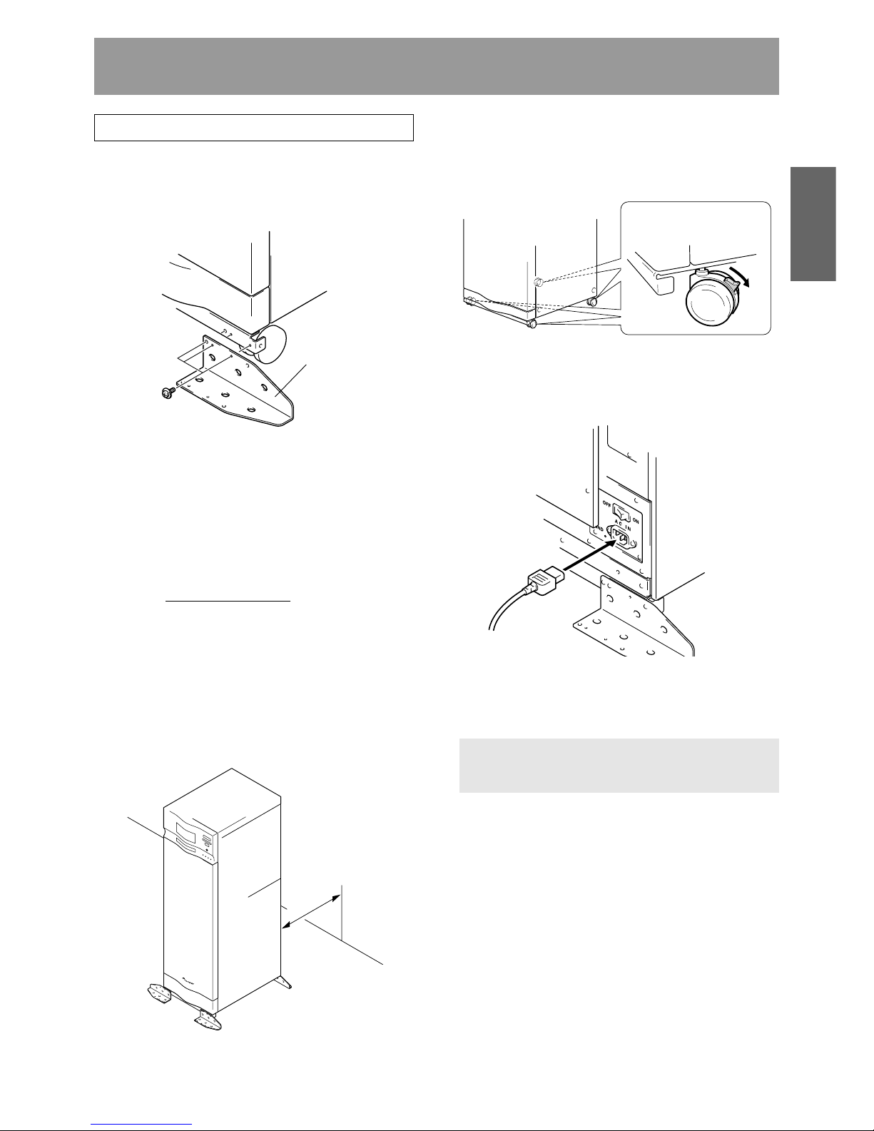
STEP 1
1. Attach the base stabilizers.
To prevent the unit from falling over, be sure to attach the
accessory base stabilizers. The DRM-7000 is provided with
four stabilizers (one at each corner), and the DRM3000 is
provided with two (rear corners only).
3. Lock the casters
Four casters at the bottom of DRM-7000/DRM-3000 allow it
to be moved lightly but they must be locked soon if you place
the changer on the chosen location. A caster is locked by
lowering its lever.
4. Connect power cord
Insert the power cord into the power inlet on the rear of the
changer and then insert the plug into a wall power outlet.
Minimum
of 50 cm
Base stabilizer
Lock
NOTES:
Be sure to attach the base stabilizers before doing anything
else.
Note that the base stabilizers also serve to protect the
ports and cables on the rear of the unit.
Note that any damage incurred as a result of the unit falling
over or any damage caused to the rear ports or cables as
a result of a failure to install the base stabilizers will not be
covered under warranty.
In the case of the DRM-3000, be sure to attach the
stabilizers
only to the rear corners of the unit.
2. Deciding on the location where the changer is
to be installed
The changer is designed with a rear access door which can
be opened in inserting or removing drives or disc magazines,
and the location where the changer is to be installed should
be chosen so as to allow a minimum of 50cm of space
between the rear of the changer and the nearest wall so as
to leave enough room to open the rear access door and insert
or remove drives or disc magazines.
NOTE:
Always be sure to use only the power cord supplied with
your changer.
Also be sure to follow the instructions on the label on the
package and use only that cord designed for use in the
location in which the power cord is to be used.
Installation
20
<DRC1285>
En
Installation
STEP 2
Readying the changer for operation
In order to ready the changer for operation, perform the
following steps in the order indicated.
1. Turning on the power (see p. 20)
2. Loosening the shipping screws (see p. 20)
3. Installing drive units (see p. 20)
4. Connecting SCSI cables (see p. 21)
5. Inserting disc magazines (see p. 22)
6. Closing access doors (see p. 25)
1. Turning on the power
When the power is first turned on, both the front and rear
access doors will automatically open. This is not a faulty
operation but the function of the shipping screws tightened
at the time of shipping or re-transporting.
NOTES:
Be sure not to close neither the front nor rear access door
until all drives and disc magazines have been installed.
If the door does not open when the power is turned on,
wait until the initialization routine has completed and the
LCD shows the user mode display (p. 25), then refer to p.
39 ("System Administrator Mode: Door Sub-mode") for
instructions on opening the door.
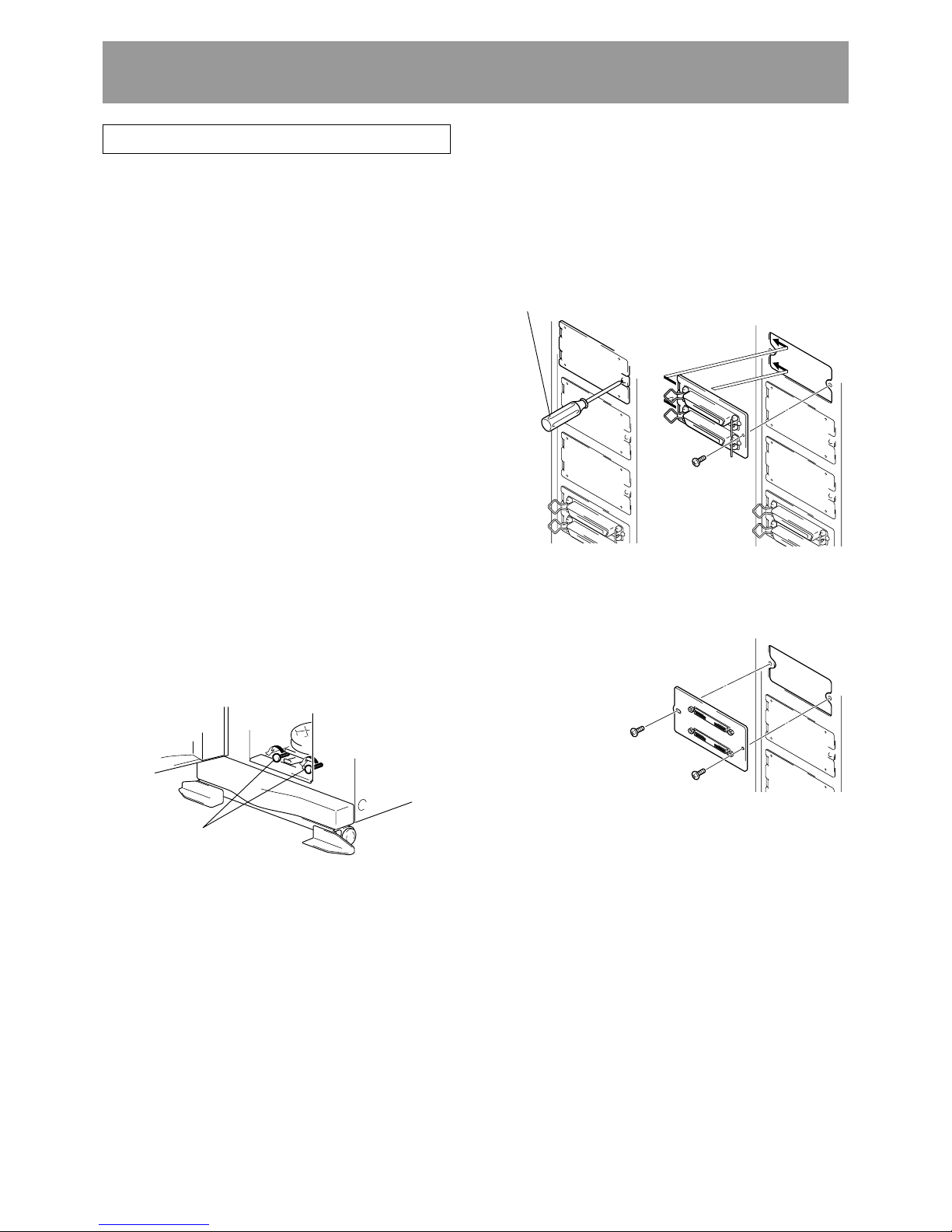
2. Loosening the shipping screws
When the front access door is opened, shipping screws may
be seen at near the bottom inside the changer. These screws
are attached to prevent damage to the built-in mechanism of
the changer during transporting.
Shipping screws are designed so that they can only be
loosened and cannot be removed so as to prevent their
becoming lost.
NOTES:
Be sure to tighten again the shipping screws before retransporting the changer.
If you or someone close the front or the rear access door
with the shipping screws loosened, the closed door can
not open automatically like before. And when the both
doors are closed, the changer starts its mechanical
initialization. So if you have not finished the installation
yet, it is necessary to open the access doors again to
continue with installation. (See System administrator
mode: Door submodes on p. 39 for further information.)
Screwdriver
Shipping screws
(1) Attaching add-on connector panels, if necessary
The connector panel provided as standard equipment is
installed under the assumption that SE drives will be
installed in rear bays #1 and #2. Remove the connector
panel if a different panel is to be installed here.
(2) Attaching drive units
Before installation, be sure to specify the following settings
at the rear of each drive to be installed. (See the operating
instructions provided with drive for details.)
¶ SCSI ID assignment
Specify the SCSI IDs to be used so as to ensure that the
same SCSI ID is not assigned by more than one drive on
the same SCSI bus.
¶ SCSI terminator settings
<SE SCSI Bus>
The terminator switch for the drive or changer at the end
of the SCSI bus should be set to ON.
<LVD SCSI Bus>
When DVD-R7783 and DRM-ULV16 are installed, it is
necessary to terminate the LVD SCSI bus.
Since the DVD-R7783 is not provided with a SCSI terminator,
an optional terminator must be purchased, or the attached
SCSI terminator (LVD) of DRM-ULV16 should be used to
provide LVD SCSI bus termination.
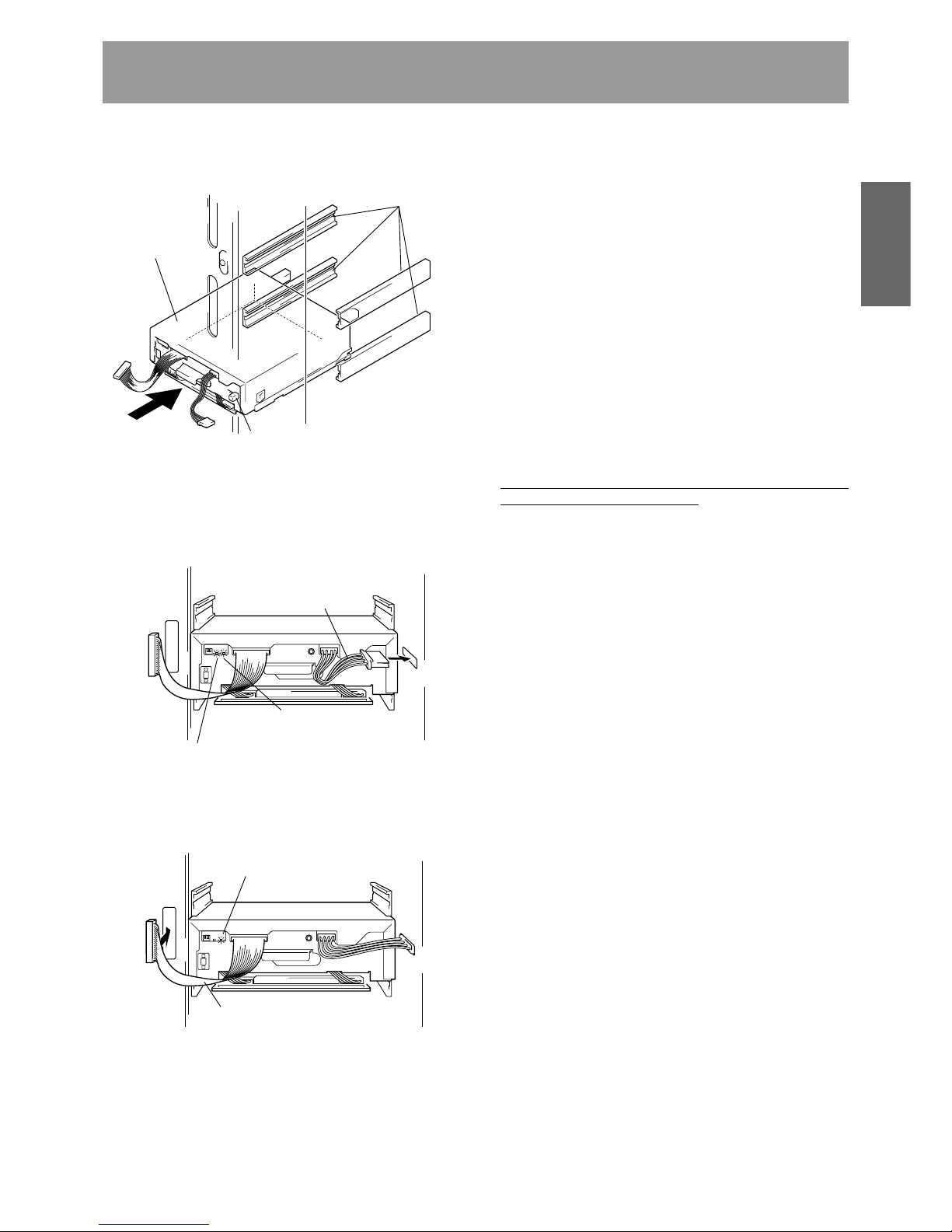
3. Installing drive units
Install drives in rear bays (in event specific bays are
designated, install in the designated bays).
When installing DRM-SN711,
DRM-SN721, use the screws
removed from the changer.
When installing DRM-LN721,
DRM-LN741, use the screws
furnished as accessories (do
not use screws removed
from changer).
21
<DRC1285>
En
English
Installation
2 Connect the power cable.
¶ When the power cable has been connected, the wiring
monitor indicator on the rear of the drive (orange) will
light up.
¶ When terminator switch is set to ON, the termination
indicator (green) also lights (does not apply to DVDR7783).
3 Connect the changer interface cable.
¶ When the changer interface cable has been connected,
the wiring monitor indicators will flash at two-second
intervals.
NOTE:
Connect the changer interface cable to the connector
corresponding to the bay in which the drives have been
installed. (Note that labels are affixed to connectors indicating
the corresponding bay number.) Note that it is extremely
important to do this, as connecting the changer interface cable
to a neighboring bay will result in damage to discs and the
disc transport mechanism.
(3) Reading and self-checking the installed drive’s SCSI
ID by the changer
¶ If all drives have been assigned different SCSI IDs, a
buzzer will sound once.
¶ If the same SCSI ID has been assigned to two or more
drives, a buzzer will sound three times.
NOTES:
If installed drives are to be connected to different SCSI
buses, then the same SCSI ID assigned to each of the
drives may be all right.
Even if none of the drives installed within a changer has
been assigned the same SCSI ID, it is necessary to check
that the same SCSI ID is not assigned to other devices
(e.g., hard disks) on the same SCSI bus.
4. Connecting SCSI cables
After installing all drives and checking to make sure that they
have been properly connected, install the SCSI interface
cables.
For SCSI connections refer to the “SCSI Connection
Manual” or consult your dealer.
NOTES:
Host adapter should be set to ID 7.
The LVD SCSI bus should have a total length of 12 m or
less, and SE SCSI bus should have a total length of 6 m or
less (these lengths include wiring inside changers and
between changers when multiple changers are daisychained). However, if the DRM-ULV16 is installed, SE SCSI
bus length should be 3 m or less, and no more than 3
drives can be connected to the bus. As a result, a maximum
of 3 SE drives can be installed on a single changer, and
due to the limitations on cable length, drives should be
installed in the rear bays #1 to #3.
When connecting SE drives, if one or more unused
connectors remain on the SCSI cable, the connector on
the end of the cable should be connected to the terminating
drive, and unused connectors allowed to remain the middle
of the cable (see page 18, examples 1, 3, 4, 6).
The changer SCSI termination switch is set to ON at the
time of shipment. Always make sure that the changer SCSI
termination switch is set to OFF when the changer is not
the last device in the SCSI chain (see page 18, examples
1, 3, 4, 6).
Note that the DRM-7000/DRM-3000 is unable to recognize
the existence of faulty SCSI cable connections or mistakes
in the assignment of SCSI IDs, and for this reason you
should always be sure to restart the host computer after
installation to make sure that all drive units and the changer
are properly recognized. This is the only way of confirming
that all SCSI devices are installed properly.
When connecting a host computer, turn off power to both
changer and host computer before performing the
connection. After connections are completed, turn on
power to the changer first, followed by power to host
computer.
Power cable
Wiring monitor indicator
Termination indicator
(Busy indicator on DVD-R7783)
Changer interface cable
Wiring monitor indicator
Guide rails
Lock lever
Drive
1 When inserting a drive, be sure to place the drive on the
changer guide rails and push the drive in until the lock
lever on the drive shifts to the locked position. Maybe you
can hear a clicking sound then.
22
<DRC1285>
En
Label
Guide rails
≠
Installation
Lock pin
Lock release Lock
Release knob
5. Inserting disc magazines
Any of the following methods may be used to insert discs
into the changer:
(1) Insert discs into a normal-type 50-disc magazine and then
insert the magazine into the changer.
(2) Insert discs into a 20-disc hyper magazine and then insert
the magazine into the changer.
(3) Use the control panel to specify the slot into which a disc
is to be inserted and transport a disc to the specified slot
from the mailslot.
(4)Issue some commands from the host computer to open
the mailslot and transport a disc to the specified slot from
the mailslot.
(5) Issue some commands from the host computer to move
discs in the loaded hyper magazine to some slots within
the loaded 50-disc magazines.
¶ Hyper magazine is not able to be inserted or removed when
the power to the changer is turned off.
¶ Methods (3) through (5) may be used after the changer is
ready for operation. When inserting discs in these
methods, always be sure to insert empty disc magazines
first.
Also note that methods (3) through (5) are used when
inserting locked-type 50-disc magazines. (See System
administrator mode: Mailslot submode on p. 36 for further
information.)
¶ Whether or not it is possible to use methods (4) and (5)
depends on the function of changer control software being
used, and you should check the manual which comes with
the software to check if it supports these methods to insert
discs.
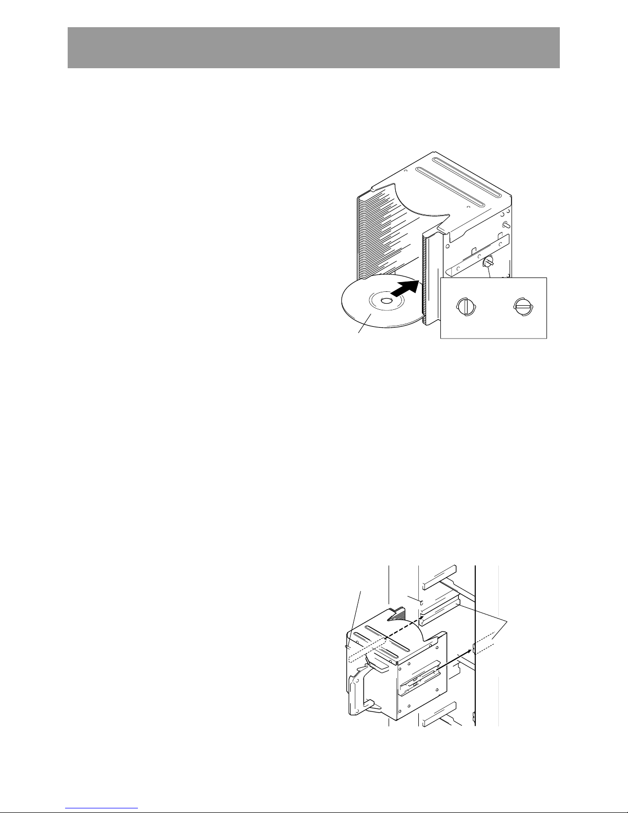
(1) Insert discs into a normal-type 50-disc magazine and
insert the magazine into the changer.
1 Turn the release knob to the vertical direction to unlock.
2 Insert discs.
3 Turn the release knob to the horizontal direction to lock
the discs into place.
NOTES:
Insert with label facing upward.
Insert discs horizontally. Otherwise it may result in
damage to the discs.
Be careful not to scratch the reflective signal recording
surface.
Do not turn a disc magazine upside down while the
lock is disengaged. Otherwise it may result in discs
falling out of the magazine.
4 Insert magazine into changer.
Holding the handle of the disc magazine, insert the disc
magazine into the changer following the changer guide
rails until it runs against the stopper.
And turn the handle to the left with pushing the magazine
in so that the lock pin on the left of the magazine slides
into the corresponding hole along the side of the changer.
Hole
Example: Loading magazine in front bay
The changer cannot recognize a drive unless the changer
interface cable is connected. Confirm connections by
looking at the wiring monitor indicator on the rear of the
drive.
=
If the indicator is lighted, confirm that the changer
interface cable is connected properly.
=
If the indicator is not lighted, confirm that the power
cable is connected properly. If connectors must be
reconnected, reconnect the power cable first, followed
by the changer interface cable.
Despite the fact that the drive is recognized, if the drive’s
model name is not displayed on the lower LCD, disconnect
all three cables and reconnect them again.
Disconnect cables in the following order:
1. SCSI interface cable
2. Changer interface cable
3. Power cable
Connect cables in the following order:
1. Power cable
2. Changer interface cable
3. SCSI interface cable
23
<DRC1285>
En
English
Installation
Label
E
S
C
EN
T
F
U
N
CT
I
O
N
LOCK
P
O
W
E
R
U
N
LO
C
K
R
O
B
O
T
IC
S
B
US
Y
DR
IV
E
B
US
Y
M
AIL
S
L
O
T
O
C
C
UP
IE
D
Lock release Lock
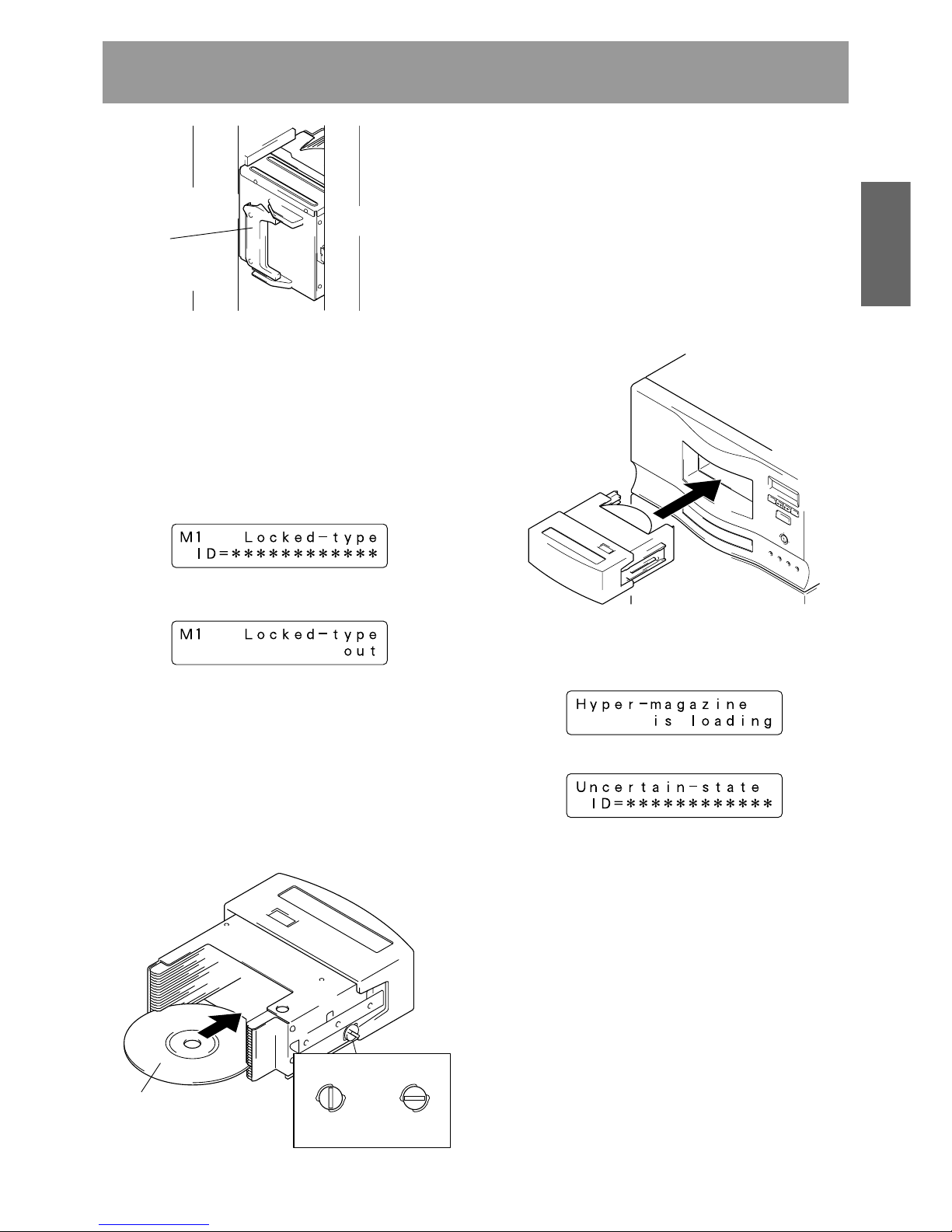
Whenever a disc magazine is inserted into the changer,
its ID will be automatically read in and displayed on the
LCD message window within a few seconds.
A similar message will also be displayed whenever a disc
magazine has been removed.
If both of these messages appear together in rapid
succession, it indicates that a disc magazine has not been
correctly inserted, and you should check the magazine to
make sure that it has been inserted properly again.
(2) Insert discs into a 20-disc hyper magazine and insert
the magazine into the changer.
1 Turn the release knob to the vertical direction to unlock.
2 Insert discs.
3 Turn the release knob to the horizontal direction to lock
the discs into place.
4 Insert magazine into changer.
Once the hyper magazine has been inserted partly into
the changer, it will be automatically loaded in.
NOTES:
Insert with label facing upward.
Insert discs horizontally. Otherwise it may result in
damage to the discs.
Be careful not to scratch the reflective signal recording
surface.
Do not turn a disc magazine upside down while the
lock is disengaged. Otherwise it may result in discs
falling out of the magazine.
Release knob
When the hyper magazine has been loaded, a unique
magazine ID will be displayed together with the record of
the locking mechanism.
≠
Note that the magazine will be automatically ejected if the
changer is unable to read the magazine ID, and that if this
happens you should try inserting the magazine again.
NOTE:
If hyper magazine has been installed, see the instructions
given in System administrator mode: Hyper submode (p. 37)
removing the hyper magazine.
Handle
Shown above is the insertion to the front magazine bay.
Though the insertion to the rear magazine bay is almost
same but note that the proper installation position is in the
place where it is very secluded.
To remove a disc magazine from the changer, pull the
handle towards you and pull the magazine from the
changer.

24
<DRC1285>
En
Serial numbers are assigned to each of the slots within the changer into which discs may be inserted. Note that these numbers are
assigned even when no disc magazine has been inserted, and that for this reason slot numbers never change even when a new
disc magazine is inserted.
Slot 20 #770 hyp-20
Hyper magazine
to to to
Hyper
Slot 1 #751 hyp-01
Slot 50 #350 M7-50
Magazine bay 7
to to to
M7
Slot 1 #301 M7-01
Slot 50 #300 M6-50
Magazine bay 6
to to to
M6
Slot 1 #251 M6-01
Slot 50 #250 M5-50
Magazine bay 5
to to to
M5
Slot 1 #201 M5-01
Slot 50 #200 M4-50
Magazine bay 4
to to to
M4
Slot 1 #151 M4-01
Slot 50 #150 M3-50
Magazine bay 3
to to to
M3
Slot 1 #101 M3-01
Slot 50 #100 M2-50
Magazine bay 2
to to to
M2
Slot 1 #051 M2-01
Slot 50 #050 M1-50
Magazine bay 1
to to to
M1
Slot 1 #001 M1-01
Slot 50 #750 M15-50
Magazine bay 15
to to to
M15
Slot 1 #701 M15-01
Slot 50 #700 M14-50
Magazine bay 14
to to to
M14
Slot 1 #651 M14-01
Slot 50 #650 M13-50
Magazine bay 13
to to to
M13
Slot 1 #601 M13-01
Slot 50 #600 M12-50
Magazine bay 12
to to to
M12
Slot 1 #551 M12-01
Slot 50 #550 M11-50
Magazine bay 11
to to to
M11
Slot 1 #501 M11-01
Slot 50 #500 M10-50
Magazine bay 10
to to to
M10
Slot 1 #451 M10-01
Slot 50 #450 M9-50
Magazine bay 9
to to to
M9
Slot 1 #401 M9-01
Slot 50 #400 M8-50
Magazine bay 8
to to to
M8
Slot 1 #351 M8-01
Slot number
Disc storage location
(Disc No.)
Slot number
Disc storage location
(Disc No.)
NOTE:
Although slot numbers reach as high as ‘770’, this does not mean that as many as 770 discs may be available within the DRM-7000.
Installation
DRM-7000
Slot 20 #370 hyp-20
Hyper magazine
to to to
Hyper
Slot 1 #351 hyp-01
Slot 50 #150 M3-50
Magazine bay 3
to to to
M3
Slot 1 #101 M3-01
Slot 50 #100 M2-50
Magazine bay 2
to to to
M2
Slot 1 #051 M2-01
Slot 50 #050 M1-50
Magazine bay 1
to to to
M1
Slot 1 #001 M1-01
Slot 50 #350 M7-50
Magazine bay 7
to to to
M7
Slot 1 #301 M7-01
Slot 50 #300 M6-50
Magazine bay 6
to to to
M6
Slot 1 #251 M6-01
Slot 50 #250 M5-50
Magazine bay 5
to to to
M5
Slot 1 #201 M5-01
Slot 50 #200 M4-50
Magazine bay 4
to to to
M4
Slot 1 #151 M4-01
Slot number
Disc storage location
(Disc No.)
Slot number
Disc storage location
(Disc No.)
DRM-3000
NOTE:
Although slot numbers reach as high as ‘370’, this does not mean that as many as 370 discs may be available within the DRM-3000.
25
<DRC1285>
En
English
Installation
6. Closing access doors
First check to make sure that all components have been
installed into place and all cables have been connected.
If this has been done, close the front and the rear access
doors, then the initialization of the changer mechanism will
begin.
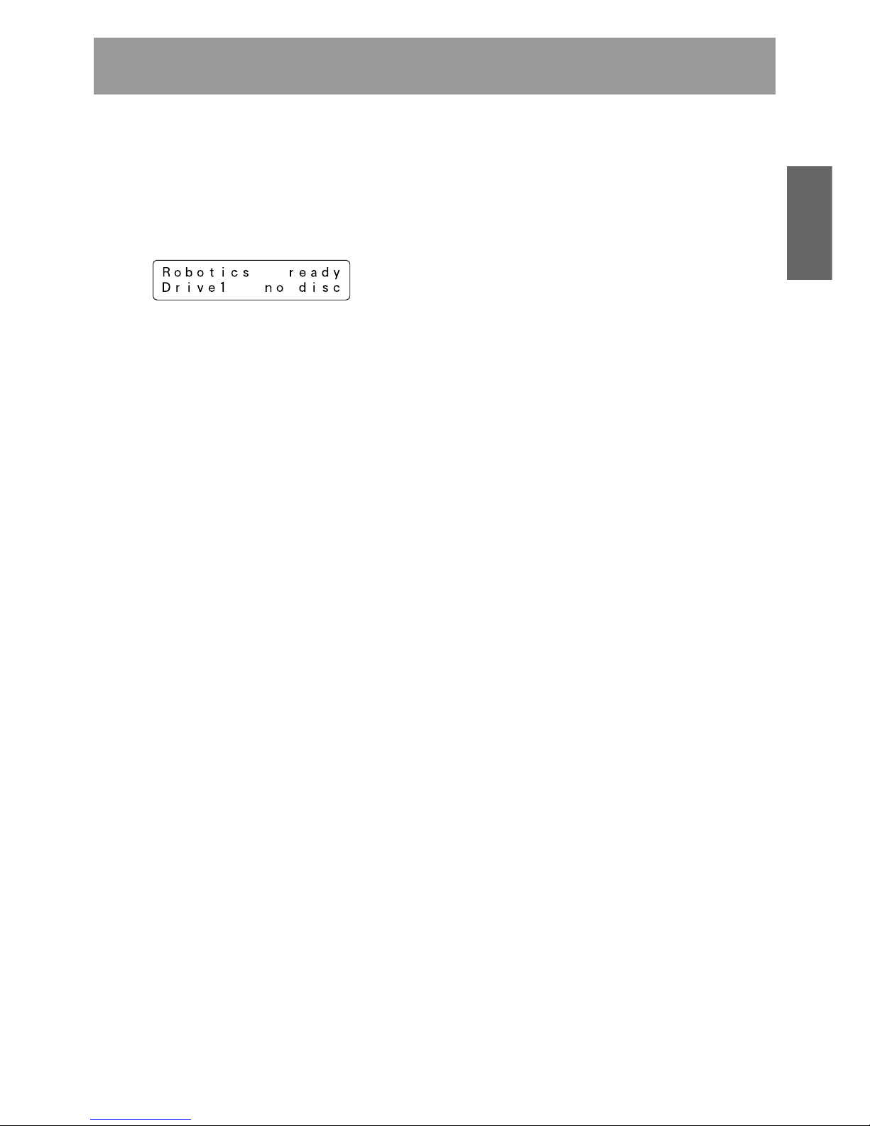
When initialization has been completed, a message like that
shown below will be displayed on the LCD message window.
The first line of this message is used to indicate the status of
the disc changer mechanism, and the second line is used to
indicate the installed drive number and to indicate whether
or not a disc has been loaded into the drive in question.
Drive numbers are assigned in sequence from the lowermost
to the uppermost drive.
NOTE:
If the maximum number of drives appears on the LCD
message window is shorter than the number of drives
installed, open the rear access door and check the power
cables and the changer interface cables to all drives installed.
(See System administrator mode: Door submodes on p. 39
for information on how to open the rear access door.)
26
<DRC1285>
En
The Pioneer DRM-7000/DRM-3000 has two operation modes.
One is user mode performing the computer-based operations
and the other is system administrator mode mainly performing
manual operations from the control panel. By dividing the
admitted operations into these two modes, it becomes
possible to prevent interference, conflicts, or clashes
occurring between operations performed from the control
panel and commands issued by the host computer.
USER MODE
Once a changer has been finished its power on initialization
or closing doors after installation, it will enter user mode and
it will become able to be controlled by the changer control
software and database management software running on the
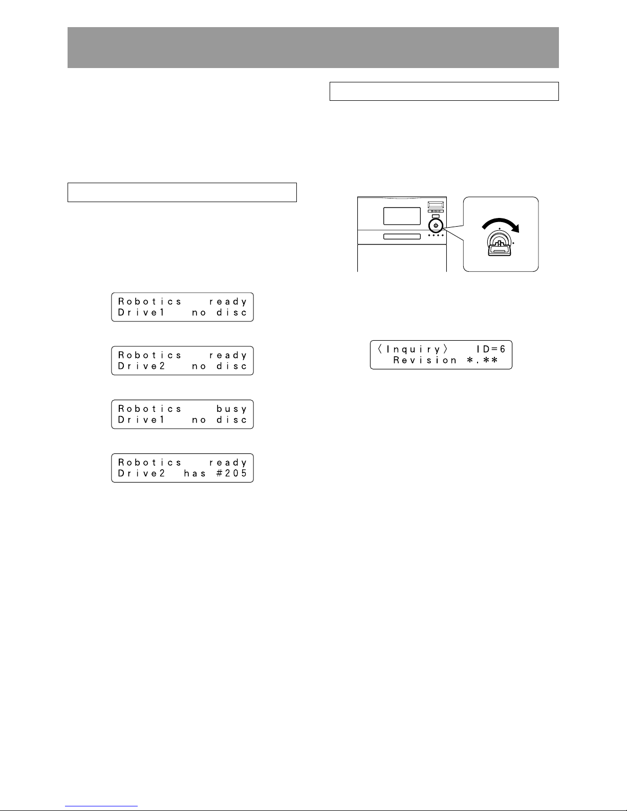
host computer. When a changer is running normally in user
mode, the LCD message window will display a series of the
following status messages in one-second intervals.
≠
≠
≠
≠
•
•
When operating in user mode, the changer will operate in
accordance with commands issued by the host computer.
SYSTEM ADMINISTRATOR MODE
The privilege to perform operations from the control panel is
given to the system administrator who keeps lock release
keys. Note that the following steps must be performed in
order to switch to system administrator mode.
1. Insert lock release key into the key switch located on the
control panel and rotate 90 degrees to shift the switch to
UNLOCK position.
OPERATION
2. Press the FUNCTION key.
When the changer enters system administrator mode, a
message like that shown below will be displayed on the LCD
message window:
System administrator mode is further divided into 8 different
submodes.
Information submodes
These submodes enable the system administrator to read a
changer’s current settings or read data stored within a
changer. Note that these submodes do not affect the
operations performed by the host computer and the system
administrator can obtain a variety of information without
interfering with the control of the changer from the host
computer.
¶ Inquiry submode (see p. 28)
¶ Config submode (see p. 28)
¶ Option submode (see p. 30)
¶ Info submode (see p. 34)
Maintenance submodes
These submodes are used to maintain discs and their status
within the changer. Sometimes these submodes may use
the disc transport mechanism. Therefore whenever the
changer enter any one of these submodes, some commands
issued by the host computer may be ignored.
¶ Mailslot submode (see p. 36)
¶ Hyper submode (see p. 37)
¶ Probe submode (see p. 38)
¶ Door submode (see p. 39)
ESC ENT
FUNCTION
LOCK
POWER
UNLOCK
ROBOTICS
BUSY
DRIVE
BUSY
MAIL SLOT
OCCUPIED
LOCK
UNLOCK
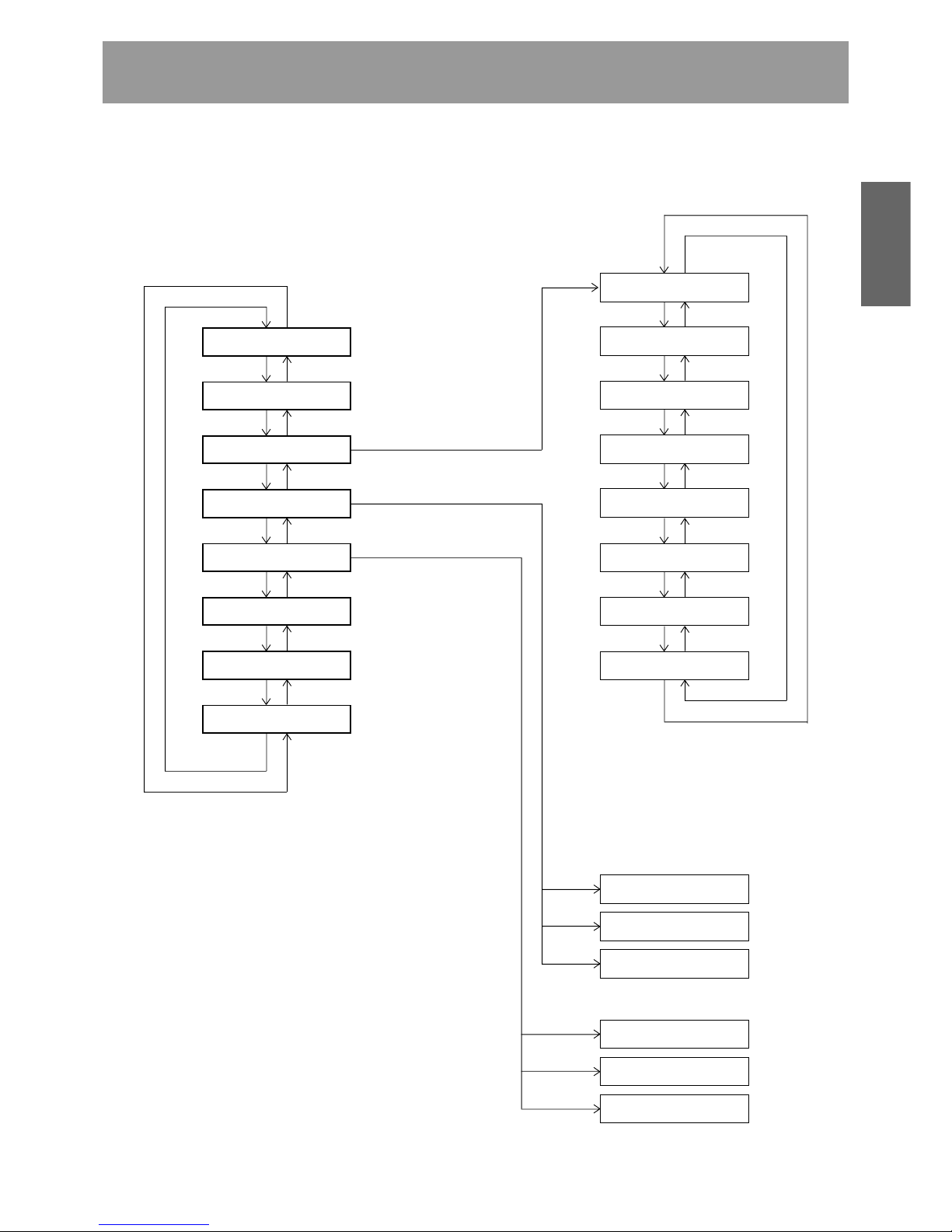
27
<DRC1285>
En
English
Operation
Press « key Press » key
Inquiry submode
Config submode
Option submode
Info submode
Mailslot submode
Hyper submode
Probe submode
Door submode
Press « key Press » key
Press « key Press » key
Press « key Press » key
Press « key Press » key
Press « key Press » key
Press « key Press » key
Press « key
Press « key Press » key
Auto probing
Hot start
Auto eject
Hyper I/E
Alert buzzer
Fan NG message
Press « key Press » key
Press « key Press » key
Press « key Press » key
Press « key Press » key
Press » key
Press » key
Press « key
Log
Contents
Run-statistics
Swap
Remove
Add
NOTE:
The DRM-7000/DRM-3000 is designed so as to prohibit the
use of maintenance submodes from the host computer. Note
that while it is possible to enter system administrator mode
even though the use of these submodes is prohibited, only
the information submodes will be able to be used.
System administrator mode settings screen are displayed in
the sequence indicated below.
Pressing the ESC key when in inquiry submode will cause
the system to return from system administrator mode to user
mode.
Press the ENT key
Press the ENT key to select
a category and then press
the ENT key again
Press the ENT key to select
the operation to be
performed and then press
the ENT key again
Free message
Inquiry change
Press « key Press » key
Press « key Press » key
NOTES:
Do not change the setting of the Inquiry change
function. Units are preset at the factory to DRM7000 (for DRM-7000 model) and DRM-3000 (for
the DRM-3000 model).
Do not change the setting of the Fan NG
message function. Units are set to factory
default of ON.
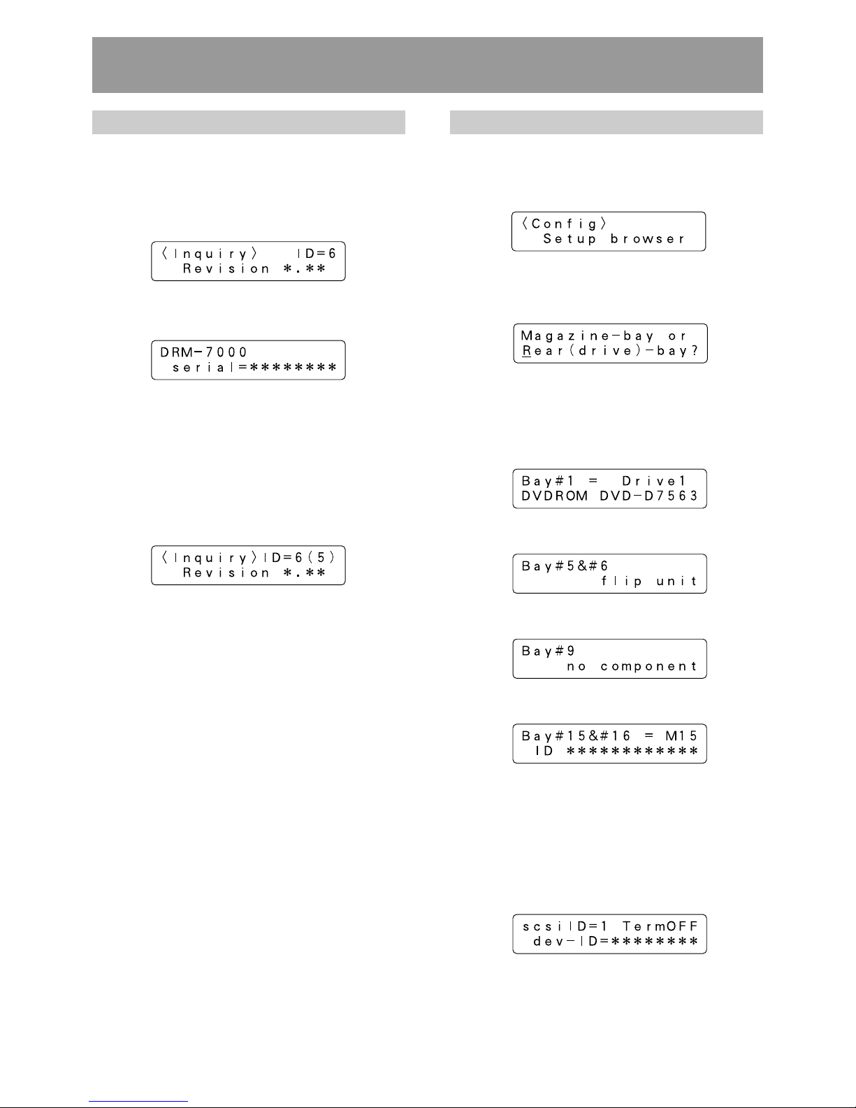
28
<DRC1285>
En
Config submode
Config submode is the mode to browse the current status of
the magazine bays and the rear bays. It may be used to make
sure that all components currently installed in the changer
have been properly recognized by the changer.
Pressing the ENT key causes the display to switch to the
‘select bay’ screen. Press the « or » key to select either the
magazine bay or the rear bay.
Operation when the rear bay has been selected
Pressing the ENT key first displays the component loaded in
rear bay #1.
¶ The bay number to be displayed is selected by pressing
the » or « key.
Press » or « key
≠
Press » or « key
≠
Press » or « key
≠
¶ If the component that has been inserted in the bay
displayed is a drive unit, it is possible to read out the SCSI
ID, termination switch settings, and device ID of the drive
in question.
Press the ENT key when the displayed is the bay in which
a drive has been inserted, then it displays the above
information.
Operation
Inquiry submode
Inquiry submode is the entry to system administrator mode
and also the exit to user mode. Here the DRM-7000/DRM3000 displays information its own. The data displayed is the
same as that obtained when the host computer issues an
SCSI INQUIRY command to the changer. Your changer’s
current SCSI ID and the firmware revision is seen here.
Pressing the ENT key at this time then the changer’s model
name and device ID (i.e., serial number) to be displayed.
Pressing the ESC key causes the display to return one level
above from the message currently being displayed.
To change the changer’s SCSI ID, use the SCSI ID switch
located at the lower left at the rear of the changer.
When the setting value of the SCSI ID switch is altered, the
display will show a message like that shown below. (Note
that the message shown here is the message which would
be displayed when the SCSI ID is changed from ‘6’ to ‘5’.)
The SCSI ID will be updated only when the power to the
changer is turned OFF and ON or the host computer resets
the SCSI bus on which the changer is.
Example of display for DRM-7000
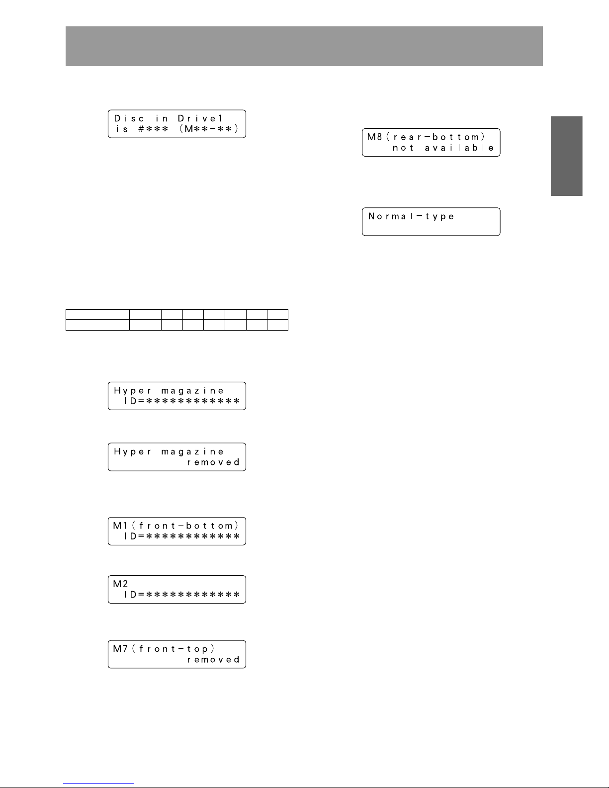
29
<DRC1285>
En
English
Operation
As the rear bays are multipurpose bays, sometimes some
bays cannot be used as magazine bays because drives
have been installed instead. Then the message displayed
will be like that indicated below.
¶ When you wish to check to see what type of disc magazine
has been installed, press the ENT key.
¶ Pressing the » key while magazine bay 15 (M15) is being
displayed will cause the display to return to a hyper
magazine display.
When you wish to view drives, press the ESC key to return
to the ‘select bay’ screen and then select the rear bay.
NOTE:
Some types of stored information are in layers. Then pressing
the ENT key may cause the display to proceed to the next
layer and pressing the ESC key causes the display to return
one level above from the message currently being displayed.
Note that pressing the ESC key too many times will cause
the system to return to user mode.
¶ If a disc has been transported to the drive, it is also possible
to press the ENT key to display the disc number.
To confirm the type of magazine installed, press the ESC
key to return to the bay select screen, then select the
desired magazine bay.
NOTE:
Some types of stored information are in layers. Then pressing
the ENT key may cause the display to proceed to the next
layer and pressing the ESC key causes the display to return
one level above from the message currently being displayed.
Note that pressing the ESC key too many times will cause
the system to return to user mode.
Operation when the magazine bay has been selected
¶ Pressing the ENT key will cause the hyper magazine ID to
be displayed.
If a hyper magazine is not inserted, the following message
will be displayed instead.
¶ Pressing the » key while a hyper magazine is being
displayed will cause the magazine IDs to be displayed in
sequence beginning from magazine bay 1 (M1).
Press » key
≠
When no disc magazine has been inserted, the message
displayed will be as indicated below.
Example of display for DRM-7000
Example of display for DRM-7000
Further, if a DVD-R7783 unit is operated with SCSI ID 10-15,
the LCD will display A-F as follows:
SCSI ID 1 – 9 101112131415
LCD display 1 – 9ABCDEF
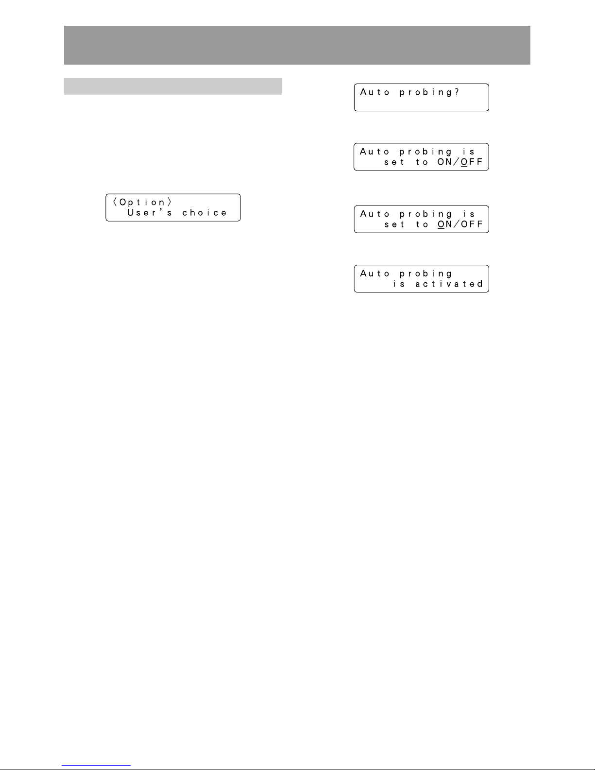
30
<DRC1285>
En
Option submode
Some changer functions may be selected at user request. In
order to allow system administrators to make the most of
the features provided by changer control software and
database management software, optional functions may be
selected as needed. Note that requirements concerning
security levels or operations performed at the time of errors
may also change depending on the location in which the
changer has been installed, and that options should be
selected accordingly.
Option submode may be used to specify the following optional
functions.
1. Auto probing (Set OFF at the time of shipment)
2. Hot start (Set OFF at the time of shipment)
3. Auto eject (Set ON at the time of shipment)
4. Hyper I/E (Set ON at the time of shipment)
5. Alert buzzer (Set ON at the time of shipment)
6. Free message (Set OFF at the time of shipment)
1. Auto probing
It is possible that discs have been inserted into normal-type
50-disc magazines and hyper magazines before these
magazines are inserted into the changer. But it does not mean
that these imported discs are ready to use because the
changer and the host computer have not recognized yet which
slot holds a disc or not. Therefore the first thing to do is
examining which slot a disc is in, that is called probing.
While this probing function is usually performed by the
changer control software running on the host computer, in
cases where users wish to perform this before connecting
the changer to the host computer or in cases where the
changer control software being used does not support such
probing function, probe submode (see p. 38) may be used
instead. Using probe submode, however, may be
inconvenient since it requires that all of the disc magazines
to be checked be specified one by one.
Auto probing may be used to have the changer automatically
check all disc magazines which need to be checked to
determine whether or not discs have been inserted.
Operation
Press the ENT key
≠
Press the | key to set to ON
≠
Press the ENT key
≠
(Note that an “Auto probing is prohibited” message will
be displayed if auto probing is set to OFF.)
Note that even after switching auto probing function from
OFF to ON, auto probing will not actually be performed until
a reset is performed, a hyper magazine is inserted or the
mechanism initialization is finished after access doors are
closed.
When auto probing begins, the changer will begin to check
whether all slots of the disc magazines to be checked in
sequence to determine whether they are “empty” or “full”.
To turn auto probing temporarily off, turn the key switch to
UNLOCK position and press the ESC key.
NOTES:
It takes approximately 2 minutes to check a 50-disc
magazine.
Some commands from the host computer cannot be
executed while auto probing is being performed.
 Loading...