

Pioneer DMP-555 Service manual

PIONEER CORPORATION 4-1, Meguro 1-chome, Meguro-ku, Tokyo 153-8654, Japan
PIONEER ELECTRONICS (USA) INC. P.O. Box 1760, Long Beach, CA 90801-1760, U.S.A.
PIONEER EUROPE NV Haven 1087, Keetberglaan 1, 9120 Melsele, Belgium
PIONEER ELECTRONICS ASIACENTRE PTE. LTD. 253 Alexandra Road, #04-01, Singapore 159936
PIONEER CORPORATION 2002
DMP-555
DIGITAL MEDIA PLAYER
DMP-555
THIS MANUAL IS APPLICABLE TO THE FOLLOWING MODEL(S) AND TYPE(S).
Model Type Power Requirement Remarks
DMP-555 KUC AC120V
DMP-555 TL AC110-240V
DMP-555 WY AC220-240V
ORDER NO.
RRV2604
For details, refer to "Important symbols for good services" on the next page.
T-ZZY JUNE 2002 printed in Japan

1234
SAFTY INFORMATION
A
This service manual is intended for qualified service technicians ; it is not meant for the casual
do-it-yourselfer. Qualified technicians have the necessary test equipment and tools, and have been
trained to properly and safely repair complex products such as those covered by this manual.
Improperly performed repairs can adversely affect the safety and reliability of the product and may
void the warranty. If you are not qualified to perform the repair of this product properly and safely,
you should not risk trying to do so and refer the repair to a qualified service technician.
WARNING
This product contains lead in solder and certain electrical parts contain chemicals which are known to the state of California to
cause cancer, birth defects or other reproductive harm.
B
NOTICE
(FOR CANADIAN MODEL ONLY)
Fuse symbols (fast operating fuse) and/or (slow operating fuse) on PCB indicate that replacement parts
must be of identical designation.
REMARQUE
(POUR MODÈLE CANADIEN SEULEMENT)
Les symboles de fusible (fusible de type rapide) et/ou (fusible de type lent) sur CCI indiquent que les pièces
de remplacement doivent avoir la même désignation.
C
Health & Safety Code Section 25249.6 - Proposition 65
(FOR USA MODEL ONLY)
1. SAFETY PRECAUTIONS
The following check should be performed for the
continued protection of the customer and service
technician.
ANY MEASUREMENTS NOT WITHIN THE LIMITS
OUTLINED ABOVE ARE INDICATIVE OF A
POTENTIAL SHOCK HAZARD AND MUST BE
CORRECTED BEFORE RETURNING THE
APPLIANCE TO THE CUSTOMER.
LEAKAGE CURRENT CHECK
Measure leakage current to a known earth ground
D
(water pipe, conduit, etc.) by connecting a leakage
current tester such as Simpson Model 229-2 or
equivalent between the earth ground and all exposed
metal parts of the appliance (input/output terminals,
screwheads, metal overlays, control shaft, etc.). Plug
the AC line cord of the appliance directly into a 120V
AC 60Hz outlet and turn the AC power switch on. Any
current measured must not exceed 0.5mA.
Reading should
E
F
Device
under
test
Test all
exposed metal
surfaces
Also test with
plug reversed
(Using AC adapter
plug as required)
AC Leakage Test
Leakage
current
tester
not be above
0.5mA
Earth
ground
2. PRODUCT SAFETY NOTICE
Many electrical and mechanical parts in the appliance
have special safety related characteristics. These are
often not evident from visual inspection nor the
protection afforded by them necessarily can be obtained
by using replacement components rated for voltage,
wattage, etc. Replacement parts which have these
special safety characteristics are identified in this
Service Manual.
Electrical components having such features are
identified by marking with a on the schematics and on
the parts list in this Service Manual.
The use of a substitute replacement component which
does not have the same safety characteristics as the
PIONEER recommended replacement one, shown in the
parts list in this Service Manual, may create shock, fire,
or other hazards.
Product Safety is continuously under review and new
instructions are issued from time to time. For the latest
information, always consult the current PIONEER
Service Manual. A subscription to, or additional copies
of, PIONEER Service Manual may be obtained at a
nominal charge from PIONEER.
2
1234
DMP-555

5678
(VRW1094)
(PRW1233)
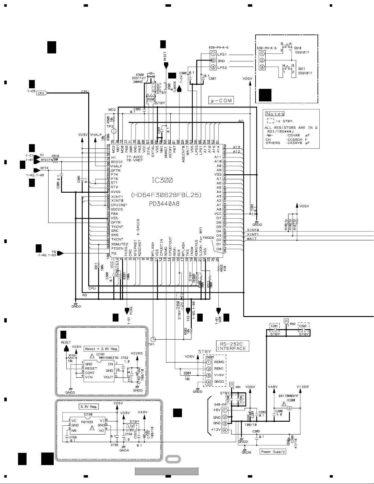
1. Laser Interlock Mechanism
The position of the switch (S510) for detecting loading completion
is detected by the system microprocessor, and the design prevents
laser diode oscillation when the switch is not in LPS1 terminal side
(when the mechanism is not clamped and LPS1 signal is high level.)
Thus, the interlock will no longer function if the switch is deliberately
set to LPS1 terminal side. ( if LPS1 signal is low level ).
In the test mode* the interlock mechanism will not function.
Laser diode oscillation will continue, if pin 4 of AN8702NFH (IC800)
on the CDPB ASSY is connected to GND, or else the terminals of
Q600 are shorted to each other (fault condition).
2. When the cover is opened, close viewing of the objective
lens with the naked eye will cause exposure to a Class 1 laser beam.
Additional Laser Caution
* Refer to pages 71.
DMP-555/WY only
DMP-555/TL only
THIS PIONEER APPARATUS CONTAINS
LASER OF CLASS 1.
SERVICING OPERATION OF THE APPARATUS
SHOULD BE DONE BY A SPECIALLY
INSTRUCTED PERSON.
MAXIMUM OUTPUT POWER: 5 mW
WAVELENGTH: 780 – 785 nm
The AEL(accessible emission level) of the laser power output is less then CLASS 1
but the laser component is capable of emitting radiation exceeding the limit for
CLASS 1.
A specially instructed person should servicing operation of the apparatus.
IMPORTANT
LASER DIODE CHARACTERISTICS
WARNING !
(DRW2102)
Printed on the Bottom Plate
A
B
C
D
E
F
56
DMP-555
7
8
3

1234
[ Important symbols for good services ]
In this manual, the symbols shown-below indicate that adjustments, settings or cleaning should be made securely.
A
When you find the procedures bearing any of the symbols, be sure to fulfill them:
1. Product safety
You should conform to the regulations governing the product (safety, radio and noise, and other regulations), and
should keep the safety during servicing by following the safety instructions described in this manual.
2. Adjustments
To keep the original performances of the product, optimum adjustments or specification confirmation is indispensable.
In accordance with the procedures or instructions described in this manual, adjustments should be performed.
3. Cleaning
B
For optical pickups, tape-deck heads, lenses and mirrors used in projection monitors, and other parts requiring cleaning,
proper cleaning should be performed to restore their performances.
4. Shipping mode and shipping screws
To protect the product from damages or failures that may be caused during transit, the shipping mode should be set or
the shipping screws should be installed before shipping out in accordance with this manual, if necessary.
5. Lubricants, glues, and replacement parts
Appropriately applying grease or glue can maintain the product performances. But improper lubrication or applying
glue may lead to failures or troubles in the product. By following the instructions in this manual, be sure to apply the
prescribed grease or glue to proper portions by the appropriate amount.For replacement parts or tools, the prescribed
C
D
ones should be used.
E
F
4
1234
DMP-555

5678
CONTENTS
SAFTY INFORMATION ........................................................................................................................................2
1. SPECIFICATIONS.............................................................................................................................................6
2. EXPLODED VIEWS AND PARTS LIST .............................................................................................................7
2.1 PACKING ....................................................................................................................................................7
2.2 EXTERIOR (1/2) SECTION........................................................................................................................8
2.3 EXTERIOR (2/2) SECTION......................................................................................................................10
2.4 SLOT-IN MECHANISM SECTION ............................................................................................................12
2.5 TRAVERSE MECHANISM ASSY-S ..........................................................................................................14
3. BLOCK DIAGRAM AND SCHEMATIC DIAGRAM ..........................................................................................16
3.1 BLOCK DIAGRAM....................................................................................................................................16
3.2 OVERALL WIRING DIAGRAM .................................................................................................................18
3.3 CDPB ASSY (1/2).....................................................................................................................................20
3.4 CDPB (2/2) and SLSW ASSYS ................................................................................................................22
3.5 MAIN ASSY (1/5)......................................................................................................................................24
3.6 MAIN ASSY (2/5)......................................................................................................................................26
3.7 MAIN (3/5) and SDCB ASSYS .................................................................................................................28
3.8 MAIN ASSY (4/5)......................................................................................................................................30
3.9 MAIN ASSY (5/5)......................................................................................................................................32
3.10 TRMB and PSWB ASSYS......................................................................................................................34
3.11 SW POWER ASSY.................................................................................................................................36
3.12 FLKB, PHTB and JOGB ASSYS ............................................................................................................38
4. PCB CONNECTION DIAGRAM ......................................................................................................................49
4.1 CDPB and SLSW ASSYS.........................................................................................................................50
4.2 MAIN and SDCB ASSYS..........................................................................................................................52
4.3 TRMB ASSYS...........................................................................................................................................56
4.4 PSWB and SW POWER ASSYS..............................................................................................................58
4.5 FLKB, PHTB and JOGB ASSYS ..............................................................................................................60
5. PCB PARTS LIST............................................................................................................................................64
6. ADJUSTMENT ................................................................................................................................................68
6.1 ADJUSTMENT ITEMS AND LOCATION ..................................................................................................68
6.2 JIGS AND MEASURING INSTRUMENTS ...............................................................................................68
6.3 NECESSARY ADJUSTMENT POINTS....................................................................................................68
6.4 ELECTRICAL ADJUSTMENT ..................................................................................................................69
7. GENERAL INFORMATION .............................................................................................................................70
7.1 DIAGNOSIS..............................................................................................................................................70
7.1.1 CLEANING.........................................................................................................................................70
7.1.2 SERVICE MODE................................................................................................................................70
7.1.3 ERROR CODE...................................................................................................................................73
7.1.4 DISASSEMBLY ..................................................................................................................................74
7.2 PARTS ......................................................................................................................................................76
7.2.1 IC........................................................................................................................................................76
8. PANEL FACILITIES .......................................................................................................................................106
A
B
C
D
56
DMP-555
E
F
7
8
5

1234
1. SPECIFICATIONS
[DMP-555/KUC, TL, WY type]
A
7 CD Player
Type Compact disc player audio system
Frequency response 4 Hz - 20 kHz
SN ratio 102 dB or more (EIAJ)
Distortion 0.003 % (EIAJ)
7 SD Memory Card
Data format SD audio format
Corresponding compression type MP3
Corresponding Bit rate 64 Kbps - 320 Kbps
Corresponding sampling rate 44.1 kHz, 48 kHz, 32 kHz
B
C
Copyright protection CPRM (SDMI compliant)
7 External interface
Computer interface USB 1.1
7 Miscellaneous
Power AC 120 V, 60 Hz (KUC type)
Power AC 110- 240 V, 50/60 Hz (TL type)
Power AC 220- 240 V, 50/60 Hz (WY type)
Power Consumption 30W
Operating temperature +5°C - +35°C
Operating humidity 5-85% RH (without condensation)
Weight 3.1 kg
Dimensions 250 (W) x 360 (D) x 103.5 (H) mm
7 Accessories
¶ Operating Instructions 1
¶ Audio cables 2
¶ Control cord 1
¶ USB cable 1
¶ Forced ejection pin 1
(found on bottom surface of player)
¶ SD memory card 1
¶ DJ application software (CD-ROM) 1
D
¶ Warranty 1 (KUC type)
NOTE:
Specifications and design are subject to possible modification without notice.
Accessories
Audio Cable
(VDE1064) L=1.5m
E
white
Red
SD Memory card
(DWX2250)
Control Cord
(PDE-319) L=1 m
DJ Application software (CD-ROM)
(DWX2249)
USB Cable
(DDE1124) L=1.8 m
Forced Eject Pin
(DEX1008)
F
6
1234
DMP-555
6
3
2
1
9
8
5
16
10
11
13
12
7
14
15
KUC type only
5678
2. EXPLODED VIEWS AND PARTS LIST
NOTES:
Parts marked by "NSP" are generally unavailable because they are not in our Master Spare Parts List.
The mark found on some component parts indicates the importance of the safety factor of the part.
Therefore, when replacing, be sure to use parts of identical designation.
Screws adjacent to mark on product are used for disassembly.
For the applying amount of lubricants or glue, follow the instructions in this manual.
(In the case of no amount instructions, apply as you think it appropriate.)
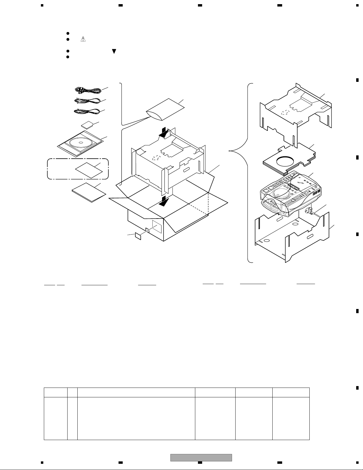
2.1 PACKING
A
B
C
PACKING parts List
Mark No. Description Part No.
1 USB Cable (L= 1.8m) DDE1124
2 Control Cord (L= 1m) PDE-319
3 Audio Cable (L=1.5m) VDE1064
4• • • • •
NSP 5 Warranty Card See Contrast table (2)
6 Forced Eject Pin DEX1008
7 Operating Instructions (English) See Contrast table (2)
7 Operating Instructions See Contrast table (2)
7 Operating Instructions See Contrast table (2)
(English/ Spanish/ Chinese)
(English/French/ German/Italian
/Dutch/Spanish)
Mark No. Description Part No.
NSP 8 DJ Application Software DWX2249
9 SD Memory Card DWX2250
NSP 10 Vinyl Bag VHL-014
11 Pad (A) DHA1546
12 Pad (B) DHA1547
13 Pad (C) DHA1548
14 Packing Case See Contrast table (2)
NSP 15 Label VRW1629
16 Mirror Mat Sheet Z23-007
(2) CONTRAST TABLE
DMP-555/KUC, TL and WY are constructed the same except for the following:
Mark No. Symbol and Description DMP-555/KUC DMP-555/TL DMP-555/WY
NSP 5 Warranty Card ARY7043 Not used Not used
7 Operating Instructions (English) DRB1321 Not used Not used
7 Operating Instructions (English/ Spanish/ Chinese) Not used DRB1322 Not used
7 Operating Instructions Not used Not used DRB1320
(English/ French/ German/ Italian/ Dutch/ Spanish)
14 Packing Case DHG2228 DHG2229 DHG2219
D
E
F
56
DMP-555
7
8
7
1234
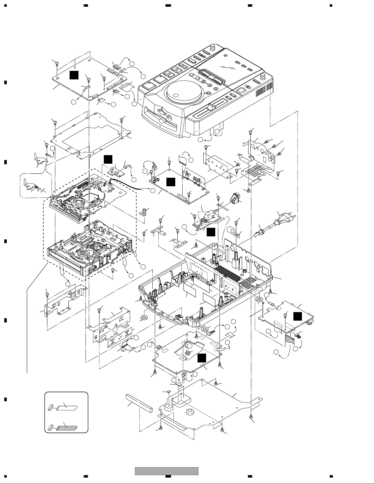
2.2 EXTERIOR (1/2) SECTION
A
B
C
33
10
No.35 Attachment
position.
OK
NG
35
33
32
14
32
32
C
1
I
35
I
11
8
B
M
34
L
7
G
36
33
F
33
G
9
33
K
33
D
12
33
13
G
C
3
33
33
13
K
33
33
J
33
WY type
only
H
32
32
15
32
18
33
24
33
F
4
32
17
19
21
16
33
20
42
33
33
H’
2
30
B
33
27
N
22
39
40
41
26
H’
H
33
33
A
B
27
43
M
E
N
23
24
33
L
5
33
E
J
F
37
E
A
32
6
33
33
29
28
C
D
33
31
32
32
33
D
33
25
E
Refer to "2.4 SLOT-IN MECHANISM SECTION".
SIDE
CONTACT SIDE
F
A
33
25
38
NON-CONTACT
8
1234
DMP-555

>
>
>
>
5678
EXTERIOR (1/2) SECTION parts List
Mark No. Description Part No.
1 MAIN Assy DWG1562
2 SLSW Assy DWS1319
3 SW POWER Assy DWR1355
4 PSWB Assy DWS1320
5 TRMB Assy DWG1559
Mark No. Description Part No.
21 Cord Stopper See Contrast table (2)
22 Chassis See Contrast table (2)
23 Insulator MO DEC2250
24 Binder ZCA-SKB90BK
25 PCB Stay DNH2495
A
6 CDPB Assy DWX2247
7 26P F•F•C/60V DDD1202
8 13P FFC/30V DDD1208
9 Mecha Plate (NET) DNH2526
10 C Earth Plate DBK1219
11 12P F•F•C/60V DDD1204
12 Earth Spring DBH1398
13 Servo Stay DNH2497
14 40P F•F•C/60V DDD1201
15 Radiation Plate DNH2498
16 Rear Stay DNH2496
17 POWER Knob DAC1895
18 Cord Clamper (Steel) RNH-184
19 Cable Stay DNF1589
20 AC Power Cord See Contrast table (2)
26 Flex Holder DEC2454
27 Insulator DEC2235
NSP 28 Silicon Rubber D5 L DEB1456
NSP 29 Silicon Rubber D5 S DEB1457
30 Cushion DEC2442
31 Bottom Plate DNH2494
32 Screw BBZ30P060FMC
33 Screw BPZ30P080FZK
34 Connector Assy 3P DKP3514
35 Cord with Plug DE005VF0
36 Connector Assy PF03PP-B25
37 Connector Assy PF04EE-S22
38 Ferrite Core DTH1188
39 Caution Label 6L See Contrast table (2)
40 Caution Label HE See Contrast table (2)
41 Caution Label See Contrast table (2)
42 Screw DBA1155
NSP 43 FPC D5 (26P) DNP1944
(2) CONTRAST TABLE
DMP-555/KUC, TL and WY are constructed the same except for the following:
Mark No. Symbol and Description DMP-555/KUC DMP-555/TL DMP-555/WY
20 AC Power Cord PDG1063 PDG1003 PDG1003
>
21 Cord Stopper CM-22C CM-22B CM-22B
22 Chassis DNK3927 DNK3928 DNK3922
39 Caution Label 6L Not used DRW2102 Not used
40 Caution Label HE Not used Not used PRW1233
B
C
41 Caution Label Not used Not used VRW1094
D
E
F
56
DMP-555
7
8
9

1234
2.3 EXTERIOR (2/2) SECTION
A
5
9
24
(3/3)
31
10
24
(2/3)
51
22
30
29
1
*
6
7
B
1
I
49
A
15
48
2
38
43
D
36
39
44
50
35
16
37
40
41
42
48
34(1/2)
C
2 x5
*
D
8
3
J
33
32
34(2/2)
11
17
21
18
20
28
23
22
12
13
14
19
24(1/3)
25
26
27
H
4
Dyefree : GEM1023 (ZLX-ME413A)
1.
*
Grease : GYA1001 (ZLB-PN397B)
2.
*
E
48
NON-CONTACT
SIDE
CONTACT SIDE
F
10
1234
48
A
48
48
DMP-555
48
48
46
48
45
48
48

5678
EXTERIOR (2/2) SECTION parts List
Mark No. Description Part No.
1 PHTB Assy DWG1560
2 SDCB Assy DWX2248
3 JOGB Assy DWG1561
4 FLKB Assy DWG1558
5 Jog Dial DNK3925
6 POM Ring DNK3926
7 Jog Washer DBF1002
8 Flange Nut M9 DBN1004
9 TEMPO Knob DAA1154
10 Slide Knob DNK2936
11 Slide Sheet 1C DAH1988
12 Display Panel DAH2038
13 TRIM Knob DAA1155
14 Control Panel DNK3921
15 Access Lamp DNK3924
16 Card Ejector DNK3995
17 Indicator DNK3941
18 RESET Knob DAC2037
19 SET Knob ISL Assy DXA1912
20 SELECT Knob DAC2010
A
B
21 Extender L (GRAY) DEC2461
22 Extender DEC2440
23 Extender R (GRAY) DEC2462
24 SET Knob (SYNC) DAC2004
25 SW Knob B DAC2012
26 EJECT Knob DAC1894
27 TEMPO CHANGE Knob DAC2007
28 MT Knob DAC2006
29 SCRATCH Knob DAC2011
30 SET Knob (RELOOP) DAC2003
31 LOOP Knob DAC2005
32 FOLDER SEARCH Knob DAC2008
33 Vessel Sheet DEC2465
34 SET Knob A Assy DXA1846
35 Lock Hook Assy DXB1764
36 Hook Spring DBH1496
37 Movable Base DNK3997
38 Base Holder DNK3996
39 M Base Spring DBH1497
40 Flap Spring DBH1499
41 Eject Lever DNK3999
42 Lever Spring DBH1498
43 Card Flap DNK3998
44 Eject Arm DNH2513
45 Earth Plate (CU) VBK1070
C
D
E
46 Flexible Cover DEC2485
47 • • • • •
48 Screw BPZ30P080FZK
49 Screw BPZ20P080FMC
50 Screw PBA1062
51 SYNC SEARCH Knob DAC2009
56
DMP-555
F
7
8
11

1234
2.4 SLOT-IN MECHANISM SECTION
A
7
17
A
3
B
18
C
10
6
4
8
2
*
15
14
2
*
A
9
1
*
13
16
5
1
2
*
2
11
12
29
Refer to
"2.5 TRAVERSE MECHANISM ASSY-S".
D
27
E
23
26
25
19
26
28
26
25
Dyefree : GEM1023 (ZLX-ME413A)
1.
*
Grease : GYA1001 (ZLB-PN397B)
2.
*
21
20
F
22
12
1234
21
DMP-555

5678
SLOT-IN MECHANISM SECTION parts List
Mark No. Description Part No.
NSP 1 DC Motor DXM1093
2 Connector Assy PF02PY-B32
3 Clamp Spring DBH1374
4 Guide Spring DBH1375
5 SW Lever Spacer (PET) DEC2420
6 Loading Lever DNK3406
7 Main Cam DNK3407
8 Lever B DNK3558
9 Lever A DNK3564
10 Clamp Arm DNK3576
11 Loading Base Assy-S DEA1022
12 Eject Lever DNK3684
NSP 13 Worm Gear DNK3910
14 Loading Gear DNK3911
15 Drive Gear DNK3912
16 Disc Guide DNK3914
17 Clamper Assy DXA1881
NSP 18 Slot-in Mechanism G5 Assy DXA1906
19 Traverse Mechanism Assy-S DXX2502
NSP 20 Float Base (G5) DNK3868
A
B
21 Vessel Cushion C DEC2457
22 Vessel Cushion A DEC2455
23 Vessel Cushion B DEC2456
24 • • • • •
25 Float Rubber D3 DEB1404
26 Float Fastener DBA1139
27 Front Sheet DED1132
28 Spacer POR (T3) DEB1566
29 DC Motor Assy-S DEA1008
C
D
E
56
DMP-555
F
7
8
13
1234
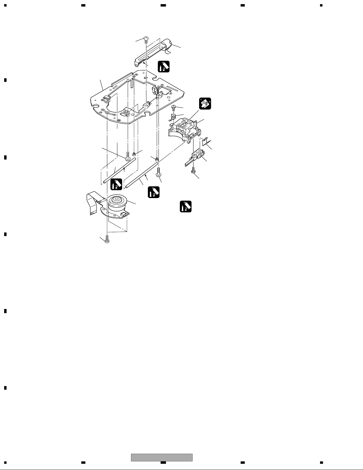
2.5 TRAVERSE MECHANISM ASSY-S
A
10
B
4
C
12
2
3
*
Cleaning liquid (GEM1004)
5
9
6
6
8
3
*
4
*
8
1
4
Cleaning paper (GED-008)
3
7
11
5
Grease: GYA1001 (ZLB-PN397B)
3.
*
Grease: GEM1007 (ZLB-PN948P)
4.
*
13
D
E
F
14
1234
DMP-555

5678
TRAVERSE MECHANISM ASSY parts List
Mark No. Description Part No.
NSP 1 Spindle Motor (S) DXM1138
NSP 2 Stepping Motor (SY) DXM1142
NSP 3 Pickup Assy VWY1069
NSP 4 Adjust Screw DBA1119
NSP 5 Precision Screw DBA1124
NSP 6 Skew Spring DBH1437
NSP 7 Joint Spring DBK1188
NSP 8 Guide Shaft DLA1840
NSP 9 Slider G4 DNK3733
NSP 10 Mechanism Frame G5 DNK3776
NSP 11 Joint DNK3777
12 Screw BPZ20P080FMC
13 Screw BPZ26P080FMC
A
B
C
D
E
56
DMP-555
F
7
8
15
1234
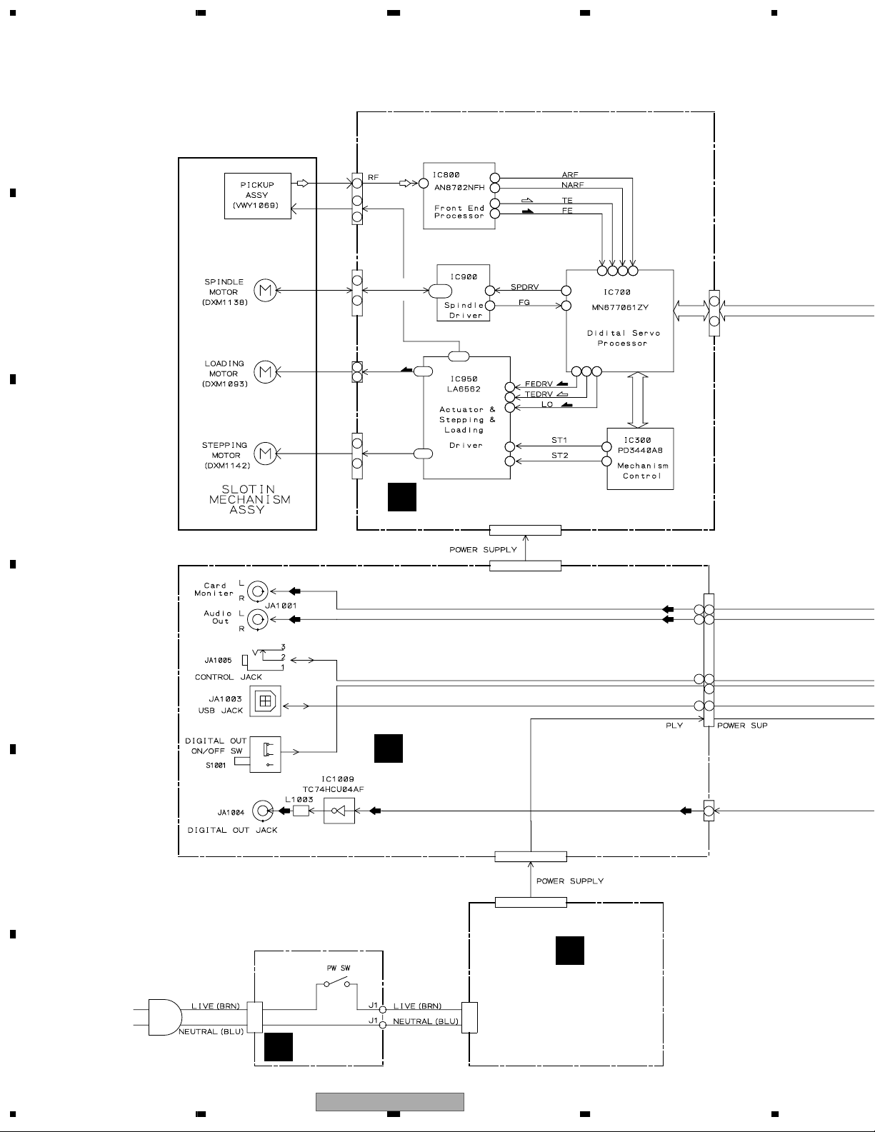
3. BLOCK DIAGRAM AND SCHEMATIC DIAGRAM
3.1 BLOCK DIAGRAM
A
CN800
11-14
4731
4730
(TS)
4718
(FS)
4722
473
472 479 478
4715
4727
4716
4720
4735
(FS)
4752
4753
475 476 4794
(TS)
(LO)
CN200
1
I
40
16
1
F+, F-
I
T+, T-
4
4747
CN900
2
B
W, V, U, HW-,HW+
I
HV-, HV+, HU-, HU+
11
CN901
1
EM+, EM-
2
(LO)
4 - 5
1 - 3
19-24
F+, FT+, T-
47
CN950
1
ST2+, ST2-
I
ST1+, ST1-
C
4
476 - 9
A
CDPB ASSY
4733
23
47
4784
4785
CN201
CN1002
(PS)
(PM)
(PS)
(PM)
1 3
24 26
5 7
20 22
D
1 3718 19
13
5 714 15
CN1003
E
TRMB ASSY
(D)
E
(D) (D)
J1001
71
CN1001
CN201
G
SW POWER ASSY
CN101CN1
F
F
PSWB ASSY
16
1234
DMP-555

5678
A
: RF SIGNAL ROUTE
(LO)
: LOADING MOTOR SIGNAL
(TS)
: TRACKING SERVO SIGNAL
(FS)
: FOCUS SERVO SIGNAL
(PM)
: PLL MAIN SIGNAL
(PS)
: PLL SUB SIGNAL
(PM)
: PB MAIN SIGNAL
(PS)
: PB SUB SIGNAL
(D)
: DIGITAL SIGNAL
(DM)
: DATA MAIN SIGNAL
(DS)
: DATA SUB SIGNAL
B
1
I
40
CN1101
39
375 381-83
377
370
368
380
371
369
396
384
374
397
386
387
189
ACLKSB
ASB, GSB
ACLKMN
AMN, GMN
(PM)
(PS)
(PM)
(PS)
324
31533336
31
33
(PS)
(PM)
1
1 3
5 7
5 7
1 378 9
5 712 13
3
14
113 16
113 16
35
32
35
31
33
32 34 327
CN1401
C
MAIN ASSY
71
(D) (D)
CN1301
CN1402
5 - 8
(DS)
(DM)
C
350
312
353
314
35
359
3
60
D
5715
(D)
5711
571
2
12
5715
16
CN1501
16
577
8
-
14
5
16
7
SDDATA1- 3
-
5
513
2
4
7
E
5 - 8
CN3001
20 -23
Display µ-com
CN4001
537
538
J7001
52
52
53
53
CN521
PHTB ASSY
I
D
H
FLKB ASSY
56
DMP-555
-
5
2
513
4
7
SDCB ASSY
7
F
17
8
1234
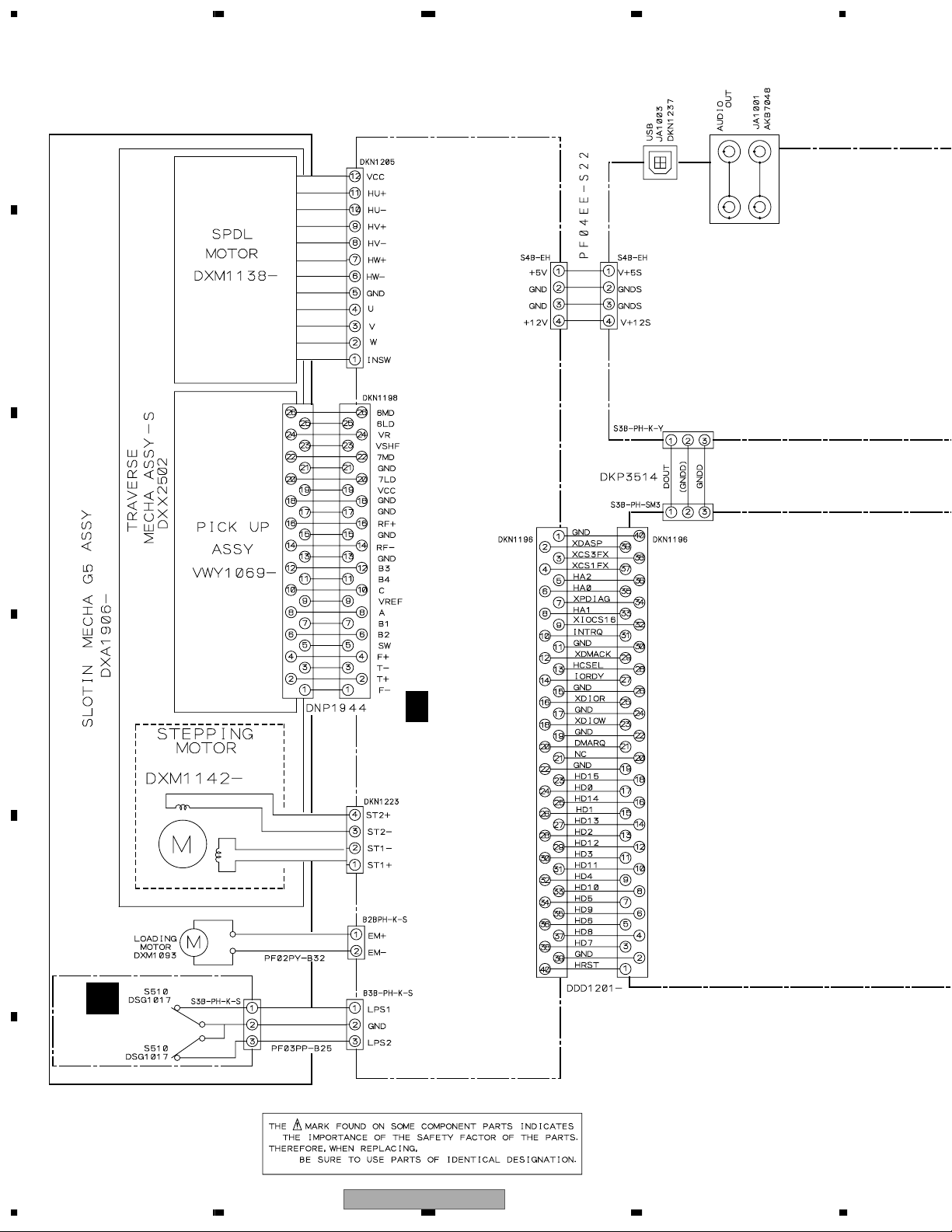
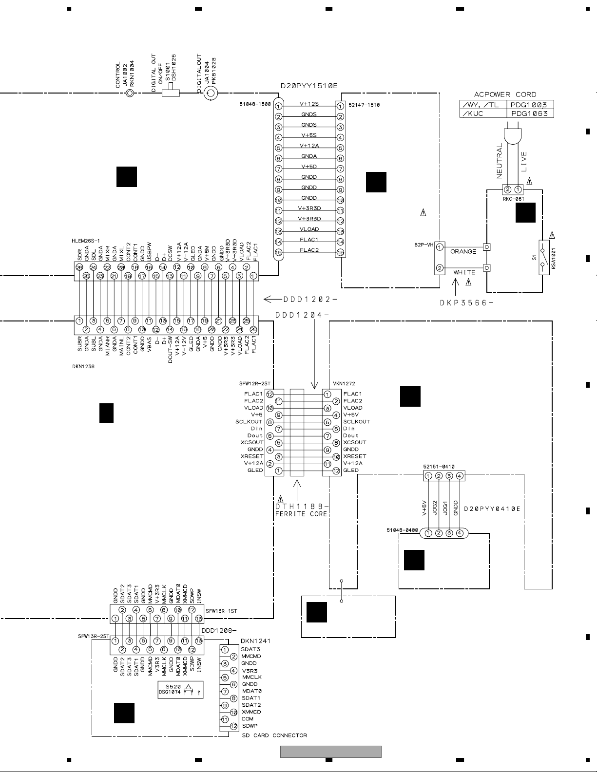
3.2 OVERALL WIRING DIAGRAM
A
B
CN900
CN800
CN201 CN1002
CN1001
CN1301
C
D
A (1/2- 2/2)
CN200
CN1101
CDPB ASSY
(DWX2247)
CN950
E
CN901
F
18
B
SLSW ASSY
(DWS1319)
1234
CN510
CN902
DMP-555
5678
A
CN1003
CN1401
TRMB ASSY
E
(DWG1559)
J1001
CN1402 CN3001
CN201
G
(DWR1355)
SW POWER ASSY
CN101
CN1
J1
J1
F
(DWS1320)
PSWB ASSY
B
C
C (1/5- 5/5)
MAIN ASSY
(DWG1562)
CN521
CN1501
CN520
JOGB ASSY
J
(DWG1561)
FLKB ASSY
H
(DWG1558)
D
CN4001
J7001
PHTB ASSY
I
J2
(DWG1560)
E
SDCB ASSY
D
(DWX2248)
56
DMP-555
F
7
8
19
1234
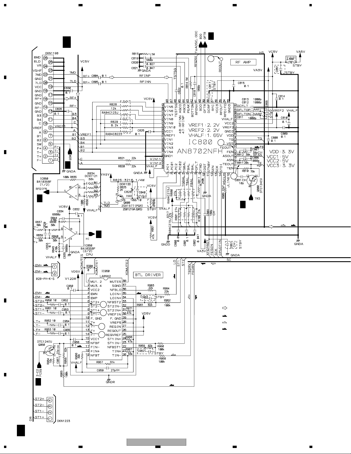
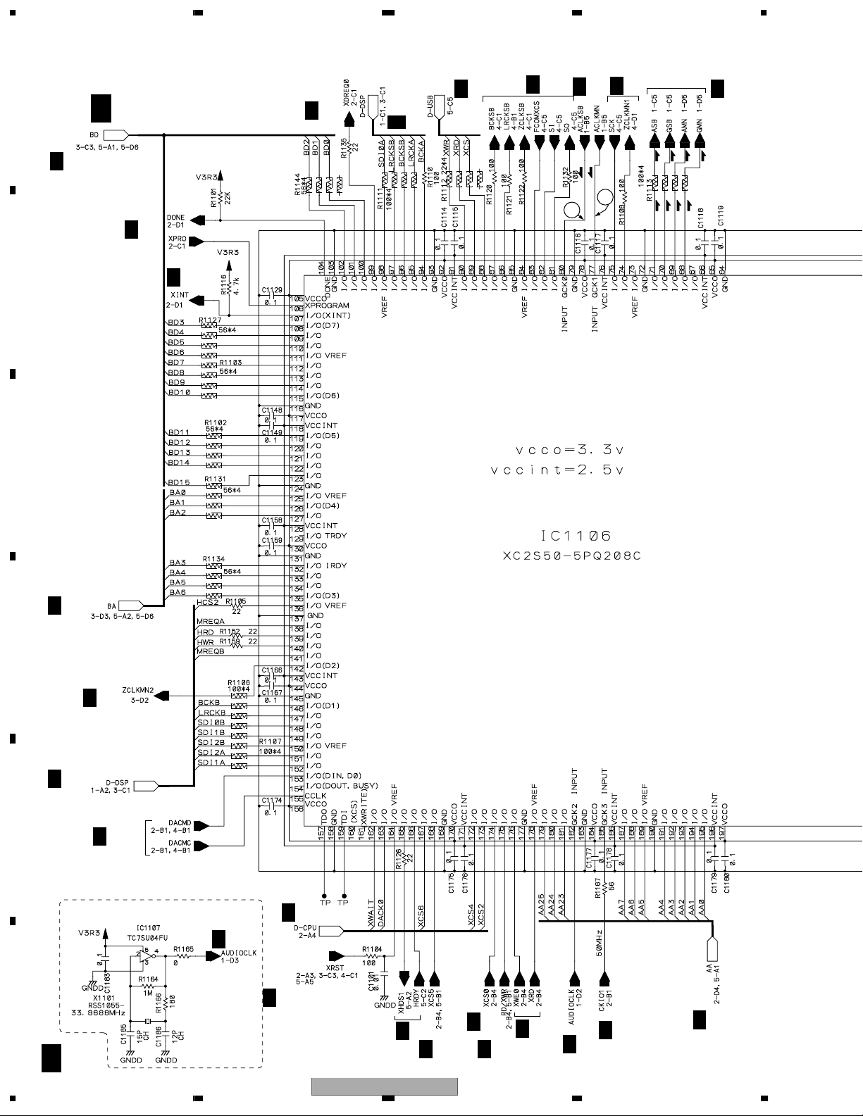
3.3 CDPB ASSY (1/2)
A
CN800
B
To Pick up Assy
A 1/2
CDPB ASSY (1/2)
(DWX2247)
A
1/2
20
23
A
2/2
21
C
A
2/2
A
2/2
D
E
CN901
(LO)
(LO)
(LO)
(LO)
To
Loading Motor
22
24
28
27
(LO)
(LO)
(TS)
(FS)
(FS)
(TS)
: RF SIGNAL ROUTE
(LO)
: LOADING MOTOR SIGNAL
(TS)
: TRACKING SERVO SIGNAL
(FS)
: FOCUS SERVO SIGNAL
(FS)
A
1/2, 2/2
(TS)
(TS)
(FS)
(FS)
A
2/2
F
A
1/2
20
To Stepping Motor
CN950
DMP-555
1234
(TS)
(FS)

5678
A
1/2
26
25
A
1/2, 2/2
A
A
1/2, 2/2
1/2
A
A
2/2
B
C
(TS)
(FS)
(FS)
(TS)
A
2/2
A
1/2
(FS)
(TS)
(TS)
(FS)
(FS)
(TS)
A
1/2
A
1/2, 2/2
A
1/2, 2/2
A
A
1/2
2/2
D
E
To Spindle Motor
CN900
56
DMP-555
F
A
1/2
7
8
21
1234
3.4 CDPB (2/2) and SLSW ASSYS
A
A 2/2
CDPB ASSY (2/2)
(DWX2247)
A
2/2
1/2
CN902
CN510
A
A
1/2
SLSW ASSY
B
(DWS1319)
B
A
1/2
A
1/2
A
1/2
C
A
1/2
D
A
1/2
A
2/2
E
2.5V (for IC700)
E
A
CN1002
1/2
CN201
A
1/2
F
22
A
3.3V (for IC100, IC300, IC700, IC800)
B
2/2
1234
DMP-555
: The power supply is shown with the marked box.

5678
A
A
1/2
B
A
A
2/2
1/2
C
D
E
CN200
C
1/5
CN1001
56
DMP-555
F
A
2/2
7
8
23
1234
3.5 MAIN ASSY (1/5)
A
MAIN ASSY (1/5)
(DWG1562)
C
3/5, 5/5
C 1/5
C
2/5
1/5, 3/5
C
C
5/5
C
4/5
C
(PS)
1/5
(PM)
C
4/5
(PS)
(PS)
(PM)
(PM)
C
1/5
4
5
C
2/5
B
C
C
2/5
SYSTEM BUS CONTROL IC
(PS)
(PS)
(PM)
(PM)
C
3/5, 5/5
D
C
3/5
C
1/5, 3/5
E
F
C
24
C
2/5, 4/5
33.8688MHz Oscillation Circuit
C
1/5
C
2/5
C
2/5, 3/5, 4/5, 5/5
C
5/5
C
C
2/5, 5/5
2/5
C
2/5, 5/5
C
2/5
C
1/5
C
2/5
C
2/5, 5/5
1/5
1234
DMP-555
5678
2.5V Circuit (for IC1106)
CN1101
C
1/5
: The power supply is shown with the marked box.
A
CN200
C
2/5
(PM)
(PM)
5V Circuit
(for VCO)
C
A
B
2/5
C
C
C
1/5
2/5
(PS)
(PS)
(PM)
C
(PS)
1/5
(PM)
(PS)
(PS)
PLL Circuit
(Audio VCO)
(PM) (PM)
D
E
56
DMP-555
C
1/5
(PM)
: PLL MAIN SIGNAL
(PS)
: PLL SUB SIGNAL
C
1/5
7
8
F
25

1234
3.6 MAIN ASSY (2/5)
A
C 2/5
MAIN ASSY (2/5)
(DWG1562)
Indicator LED
driver Circuit
C
C
5/5
1/5
C
1/5
C
3
5/5
1/5,3/5,4/5,5/5
C
5/5
C
B
C
2/5
C
C
C
1/5, 4/5
C
5/5
C
C
4/5
5/5
1/5
2/5
C
C
4/5
2/5
2
C
C
1/5
D
5/5
C
4/5
1
C
C
1/5
C
2/5
E
C
5/5
C
1/5
2/5
C
5/5
C
F
Reset Circuit
C
2/5
26
1234
C
4/5
C
DMP-555
4/5

5678
C
5/5
1.8V (for IC1207)
C
5/5
C
C
1/5
1/5
C
C
: The power supply is shown with the marked box.
1/5, 5/5
1/5, 5/5
A
B
C
16
15
1/5
C
C
D
2/5
E
C
1/5, 5/5
C
1/5
56
DMP-555
F
C
2/5
7
8
27

1234
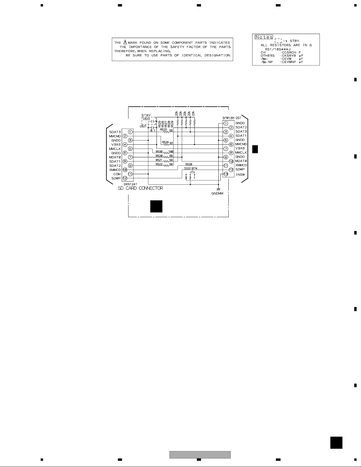
3.7 MAIN (3/5) and SDCB ASSYS
A
C 3/5
B
MAIN ASSY (3/5)
(DWG1562)
C
C
3/5
3/5
C
Master Tempo DSP
D
(DM)
(DS)
(DS)
C
1/5
E
(DM)
C
4/5
(DS)
C
1/5
(D)
C
1/5, 2/5, 4/5, 5/5
C
1/5, 5/5
C
1/5, 5/5
(D)
CN1301
1.8V Circuit
F
C
3/5
28
1234
(for IC1301)
(DM)
: DATA MAIN SIGNAL
(DS)
: DATA SUB SIGNAL
(D)
: DIGITAL SIGNAL
DMP-555
E
CN1001
: The power supply is shown with the marked box.
20MHz Oscillation Circuit
5678
A
TO SD CARD
CN520
SDCB ASSY
D
(DWX2248)
CN521
C
CN1501
5/5
B
C
D
56
DMP-555
E
F
D
7
8
29

1234
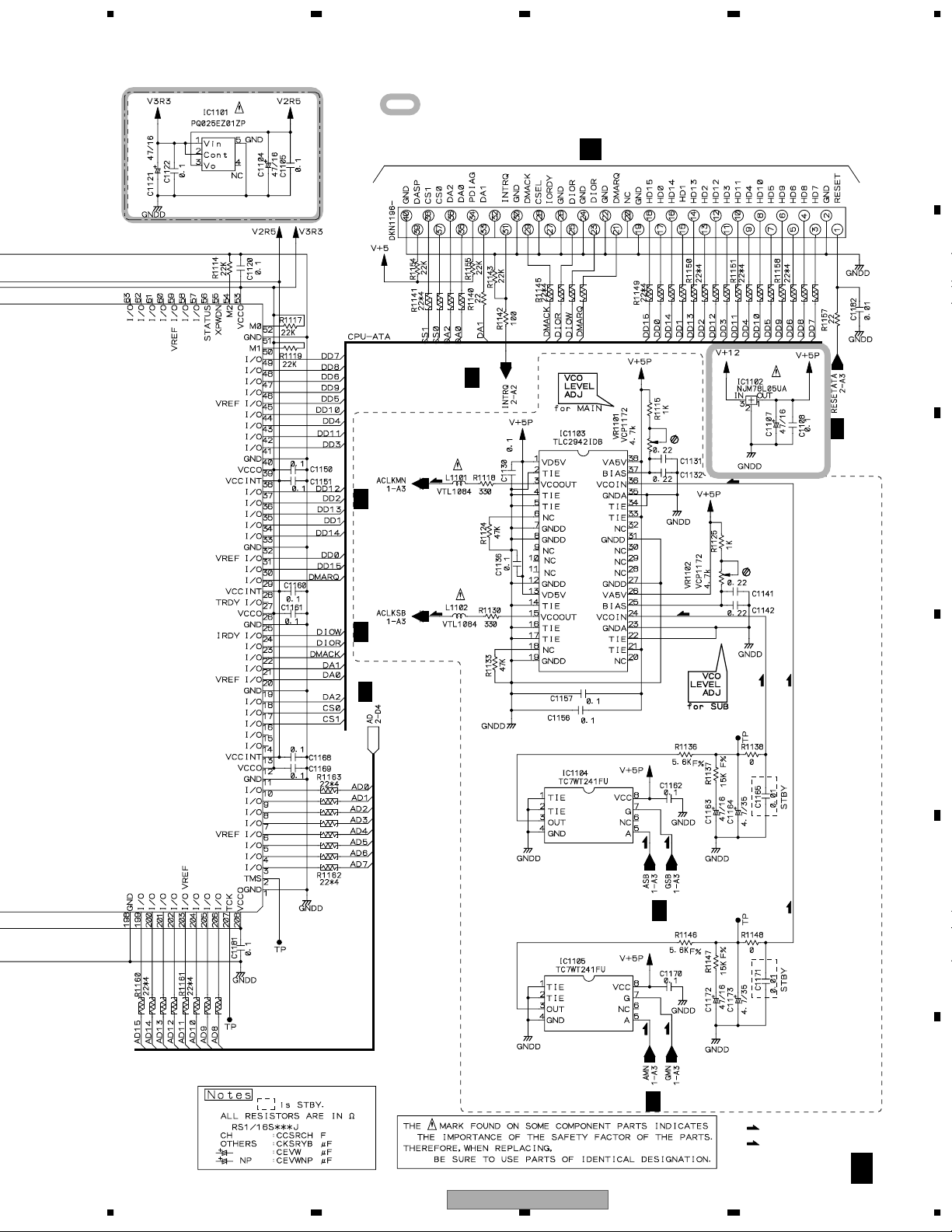
3.8 MAIN ASSY (4/5)
A
C 4/5
C
4/5
C
2/5
B
C
2/5
C
4/5
Mute Control Circuit
C
1/5, 2/5
C
C
1/5
(PS)
(PS)
MAIN ASSY (4/5)
(DWG1562)
C
4/5
(PS)
C
1/5
9
(DS)
10
C
D
E
1/5
C
1/5
C
1/5, 2/5, 3/5, 5/5
C
2/5
C
3/5
C
1/5
6
C
4/5
(DM)
(DS)(DM)
11
C
4/5
C
4/5
(PM)
(PM)
8
(DM)
7
D/A Conversion Circuit
C
4/5
F
C
4/5
30
1234
DMP-555
 Loading...