


DJ MIXER DJM-T1 TABLE DE MIXAGE
DJ-MISCHPULT
http://www.prodjnet.com/support/
The Pioneer website shown above offers FAQs, information on software and various other types of information and services to allow you to use your product in greater comfort.
Le site Pioneer ci-dessus offre une FAQ, des informations sur le logiciel et divers types d’informations et de services permettant de tirer le meilleur parti de ce produit.
Die oben gezeigte Pioneer-Website enthält häufig gestellte Fragen, Informationen über Software und andere wichtige Informationen und Dienste, die Ihnen helfen, Ihr Produkt optimal zu verwenden.
Operating Instructions Mode d’emploi Bedienungsanleitung
Thank you for buying this Pioneer product. Please read through these operating instructions so you will know how to operate your model properly. After you have finished reading the instructions, put them away in a safe place for future reference.
In some countries or regions, the shape of the power plug and power outlet may sometimes differ from that shown in the explanatory drawings. However the method of connecting and operating the unit is the same.
IMPORTANT
CAUTION
RISK OF ELECTRIC SHOCK
DO NOT OPEN
The lightning flash with arrowhead symbol, within an equilateral triangle, is intended to alert the user to the presence of uninsulated “dangerous voltage” within the product’s enclosure that may be of sufficient magnitude to constitute a risk of electric shock to persons.
CAUTION:
TO PREVENT THE RISK OF ELECTRIC SHOCK, DO NOT REMOVE COVER (OR BACK). NO USER-SERVICEABLE PARTS INSIDE. REFER SERVICING TO QUALIFIED SERVICE PERSONNEL.
The exclamation point within an equilateral triangle is intended to alert the user to the presence of important operating and maintenance (servicing) instructions in the literature accompanying the appliance.
D3-4-2-1-1_A1_En
Replacement and mounting of an AC plug on the power supply cord of this unit should be performed only by qualified service personnel.
IMPORTANT: THE MOULDED PLUG
This appliance is supplied with a moulded three pin mains plug for your safety and convenience. A 10 amp fuse is fitted in this plug.
Should the fuse need to be replaced, please ensure that the replacement fuse has a rating of 10 amps and that it is approved by ASTA or BSI to BS1362.
Check for the ASTA mark |
or the BSI mark |
on the body of the fuse. |
If the plug contains a removable fuse cover, you must ensure that it is refitted when the fuse is replaced. If you lose the fuse cover the plug must not be used until a replacement cover is obtained. A replacement fuse cover can be obtained from your local dealer.
If the fitted moulded plug is unsuitable for your socket outlet, then the fuse shall be removed and the plug cut off and disposed of safely. There is a danger of severe electrical shock if the cut off plug is inserted into any 13 amp socket.
If a new plug is to be fitted, please observe the wiring code as shown below. If in any doubt, please consult a qualified electrician.
IMPORTANT: The wires in this mains lead are coloured in accordance with the following code: Blue : Neutral Brown : Live
As the colours of the wires in the mains lead of this appliance may not correspond with the coloured markings identifying the terminals in your plug, proceed as follows;
The wire which is coloured BLUE must be connected to the terminal which is marked with the letter N or coloured BLACK.
The wire which is coloured BROWN must be connected to the terminal which is marked with the letter L or coloured RED.
How to replace the fuse: Open the fuse compartment with a screwdriver and replace the fuse.
D3-4-2-1-2-2*_A2_En
WARNING
This equipment is not waterproof. To prevent a fire or shock hazard, do not place any container filled with liquid near this equipment (such as a vase or flower pot) or expose it to dripping, splashing, rain or moisture.
D3-4-2-1-3_A1_En
WARNING
Before plugging in for the first time, read the following section carefully.
The voltage of the available power supply differs according to country or region. Be sure that the power supply voltage of the area where this unit will be used meets the required voltage (e.g., 230 V or 120 V) written on the side panel.
D3-4-2-1-4*_A1_En
WARNING
To prevent a fire hazard, do not place any naked flame sources (such as a lighted candle) on the equipment.
D3-4-2-1-7a_A1_En
Operating Environment
Operating environment temperature and humidity: +5 °C to +35 °C (+41 °F to +95 °F); less than 85 %RH (cooling vents not blocked)
Do not install this unit in a poorly ventilated area, or in locations exposed to high humidity or direct sunlight (or strong artificial light)
D3-4-2-1-7c*_A1_En
VENTILATION CAUTION
When installing this unit, make sure to leave space around the unit for ventilation to improve heat radiation (at least 5 cm at rear, and 3 cm at each side).
WARNING
Slots and openings in the cabinet are provided for ventilation to ensure reliable operation of the product, and to protect it from overheating. To prevent fire hazard, the openings should never be blocked or covered with items (such as newspapers, table-cloths, curtains) or by operating the equipment on thick carpet or a bed.
D3-4-2-1-7b*_A1_En
If the AC plug of this unit does not match the AC outlet you want to use, the plug must be removed and appropriate one fitted. Replacement and mounting of an AC plug on the power supply cord of this unit should be performed only by qualified service personnel. If connected to an AC outlet, the cut-off plug can cause severe electrical shock. Make sure it is properly disposed of after removal.
The equipment should be disconnected by removing the mains plug from the wall socket when left unused for a long period of time (for example, when on vacation).
D3-4-2-2-1a_A1_En
2 En
POWER-CORD CAUTION
Handle the power cord by the plug. Do not pull out the plug by tugging the cord and never touch the power cord when your hands are wet as this could cause a short circuit or electric shock. Do not place the unit, a piece of furniture, etc., on the power cord, or pinch the cord. Never make a knot in the cord or tie it with other cords. The power cords should be routed such that they are not likely to be stepped on. A damaged power cord can cause a fire or give you an electrical shock. Check the power cord once in a while. When you find it damaged, ask your nearest PIONEER authorized service center or your dealer for a replacement.
S002*_A1_En
Before making or changing the connections, switch off the power and disconnect the power cord from the AC outlet.
D44-9-3_A1_En
CAUTION
The POWER switch on this unit will not completely shut off all power from the AC outlet. Since the power cord serves as the main disconnect device for the unit, you will need to unplug it from the AC outlet to shut down all power. Therefore, make sure the unit has been installed so that the power cord can be easily unplugged from the AC outlet in case of an accident. To avoid fire hazard, the power cord should also be unplugged from the AC outlet when left unused for a long period of time (for example, when on vacation).
D3-4-2-2-2a*_A1_En
If you want to dispose this product, do not mix it with general household waste. There is a separate collection system for used electronic products in accordance with legislation that requires proper treatment, recovery and recycling.
Private households in the member states of the EU, in Switzerland and Norway may return their used electronic products free of charge to designated collection facilities or to a retailer (if you purchase a similar new one).
For countries not mentioned above, please contact your local authorities for the correct method of disposal.
By doing so you will ensure that your disposed product undergoes the necessary treatment, recovery and recycling and thus prevent potential negative effects on the environment and human health.
K058b_A1_En
En 3

Contents
How to read this manual
!The names of displays, menus, and buttons in this manual are enclosed in brackets. (e.g. [MASTER] channel, [ON/OFF], [File] menu)
!Descriptions of functions and procedures performed on the computer are
indicated [ TRAKTOR ].
!The TRAKTOR manual and TRAKTOR GETTING STARTED can be viewed from the TRAKTOR help menu after TRAKTOR is installed.
Before start |
|
Features............................................................................................................................ |
5 |
What’s in the box............................................................................................................. |
5 |
Quick Start Guide |
|
Operation overview.......................................................................................................... |
6 |
Installing the TRAKTOR software................................................................................... |
6 |
Launching TRAKTOR...................................................................................................... |
7 |
Performing product activation....................................................................................... |
7 |
Installing the driver software.......................................................................................... |
8 |
Connecting the input/output terminals....................................................................... |
10 |
Setting this unit.............................................................................................................. |
11 |
Changing the setting utility’s settings......................................................................... |
11 |
Playing tracks................................................................................................................. |
11 |
Operation |
|
Browse section.............................................................................................................. |
13 |
Transport section........................................................................................................... |
14 |
Mixer section.................................................................................................................. |
16 |
Effect section.................................................................................................................. |
18 |
Hot cue/sampler section............................................................................................... |
20 |
Global section................................................................................................................ |
22 |
MIC/AUX section........................................................................................................... |
22 |
MIDI section................................................................................................................... |
22 |
Changing the settings |
|
Changing the TRAKTOR Preferences.......................................................................... |
23 |
Changing the setting utility’s settings......................................................................... |
23 |
Changing this unit’s settings....................................................................................... |
25 |
List of MIDI Messages |
|
List of MIDI Messages................................................................................................... |
26 |
Additional information |
|
Troubleshooting............................................................................................................. |
28 |
Block Diagram............................................................................................................... |
29 |
Disclaimer...................................................................................................................... |
29 |
Cautions on copyrights................................................................................................. |
29 |
Specifications................................................................................................................ |
30 |
4 En

Before start
Features
This unit is a 2-channel mixer optimally designed for DJ performances using the TRAKTOR SCRATCH DJ software by Native Instruments. Through a collaboration with Native Instruments, it includes the “TRAKTOR SCRATCH DUO 2” DJ software equipped with a number of features required for DJ performances. For the hardware, the unit comes with a built-in controller for operating the many functions of TRAKTOR SCRATCH without hesitation and a sound card for simple connection to a computer. A DVS (Digital Vinyl System) can be created by combining this unit with your DJ player or analog player.
Also, this unit carries over the technology of the Pioneer DJM series which has gained a high reputation for both quality and performance, offering powerful support for not only home use but also DJ performances in club scenes.
!An even greater variety of performance functions can be enjoyed by updating to TRAKTOR SCRATCH PRO 2 (for a fee).
INTERNAL TRAKTOR CONTROLLER
This unit includes a controller optimized for TRAKTOR SCRATCH operations. TRAKTOR SCRATCH can be operated accurately, without procuring a separate controller in addition to this unit.
The section for operating the browse and transport functions is located at the top of the mixer section in function of the series of operating procedures from selecting tracks to mixing. The sections for operating the performance functions (EFFECT, LOOP, HOT CUE and SAMPLER) are placed independently at the sides for the different channels in function of the player’s layout for intuitive operation.
PLUG AND PLAY
This unit is equipped with a built-in USB sound card for connecting a computer. A computer can be connected simply using a single USB cable; there is no need to procure a separate sound card in addition to this unit.
DJ performances using “TRAKTOR SCRATCH DUO 2” can be started immediately, with no complicated settings.
HIGH DURABILITY FADER
The crossfader uses a uniquely developed magnetic system. This improves durability, maintaining smooth operation for scratch playing over a long period of time. Furthermore, the operating load, fader curve and cut lag can be adjusted to the user’s tastes. The channel fader uses a sliding structure with the fader knob supported by two metal shafts. This provides smooth operation with no shakiness and approximately 3 times the endurance as compared to previous Pioneer products. In addition, a newly developed fader is used to minimize the influence of any liquids or dust getting inside the fader.
HIGH SOUND QUALITY
Thanks to the built-in sound card, sound output from a computer can be input to this unit in digital format, eliminating any decrease in sound quality. In addition, this unit’s audio input/output circuitry includes a high performance D/A converter and unique analog circuit technology reducing digital noise, faithfully reproducing the original sound to provide powerful, high quality club sound.
What’s in the box
!TRAKTOR SCRATCH DUO 2 software DVD-ROM
!TRAKTOR SCRATCH CONTROL CD ×2
!TRAKTOR SCRATCH CONTROL VINYL ×2
!Driver software CD-ROM
!USB cable
!Power cord
!Warranty card
!Operating instructions (this document)
English
En 5
Quick Start Guide
This section describes the procedure for using this unit as a DVS (Digital Vinyl System).
! Descriptions of functions and procedures performed on the computer are indicated [ TRAKTOR ].
Operation overview
1Installing the TRAKTOR software
=page 6
2Launching TRAKTOR
=page 7
3Performing product activation
=page 7
4Installing the driver software
=page 8
5Connecting the input/output terminals
=page 10
6Setting this unit
=page 11
7Changing the setting utility’s settings
=page 11
8Playing tracks
=page 11
Installing the TRAKTOR software
!This unit also supports TRAKTOR SCRATCH PRO 2.
If you own TRAKTOR SCRATCH PRO 2, update the software to the latest version.
Cautions on installing the TRAKTOR software
Supported operating systems
Mac OS X |
10.5 |
1 |
|
10.6 |
1 |
||
|
|||
Windows® 7 Home Premium/Professional/Ultimate |
32-bit version |
1 |
|
64-bit version |
1 |
||
|
|||
Windows Vista® Home Basic/Home Premium/Business/ |
32-bit version |
1 |
|
Ultimate (SP1 or later) |
64-bit version |
1 |
|
Windows® XP Home Edition/Professional (SP3 or later) |
32-bit version |
1 |
For the latest information on the operating environment and compatibility, and to acquire the latest operating system, please visit the following Native Instruments website: http://www.native-instruments.com/traktor
Minimum operating environment for TRAKTOR
|
For Mac OS X |
Macintosh computer equipped with an Intel® Core™ |
|
|
Duo processor |
||
|
|
||
|
|
|
|
CPU |
For Windows® 7, |
PC/AT compatible computer equipped with a 2.4 GHz or |
|
|
Windows Vista® |
greater Intel® Pentium® 4, Intel® Core™ Duo or AMD |
|
|
and Windows® XP |
Athlon™ 64 processor |
|
Required |
2 GB or more of RAM |
||
memory |
|||
|
|
||
|
|
||
Hard disk |
Free space of 500 MB or greater |
||
|
|
||
DVD drive |
Optical disc drive on which DVD-ROMs are readable |
||
Internet con- |
An Internet connection environment is required for user registration with |
||
Native Instruments, to update the TRAKTOR software, etc. |
|||
nection |
|||
Use the most recent version of the web browser. |
|||
|
|||
USB 2.0 port |
A USB 2.0 port is required to connect the computer with this unit. |
||
!Full functionality is not guaranteed on all computers, even those meeting the operating environment requirements described above.
!Even with the required memory indicated for the operating environment above, lack of memory due to resident programs, the number of services, etc., could prevent the software from offering optimal functionality and performance. In such cases, free up sufficient memory. We recommend installing additional memory for stable operation.
!Depending on the computer’s power-saving settings, etc., the CPU and hard disk may not provide sufficient processing capabilities. For notebook computers in particular, make sure the computer is in the proper conditions to provide constant high performance (for example by keeping the AC power connected) when using TRAKTOR.
6 En
Installation Procedure (Windows)
1Insert the included TRAKTOR SCRATCH DUO 2 software DVD-ROM into the computer’s DVD drive.
2From the Windows [Start] menu, double-click the [Computer (or My Computer)] > [Traktor] icon.
The contents of the DVD-ROM are displayed.
3 Double-click [Traktor 2 2.0.x Setup PC.exe].
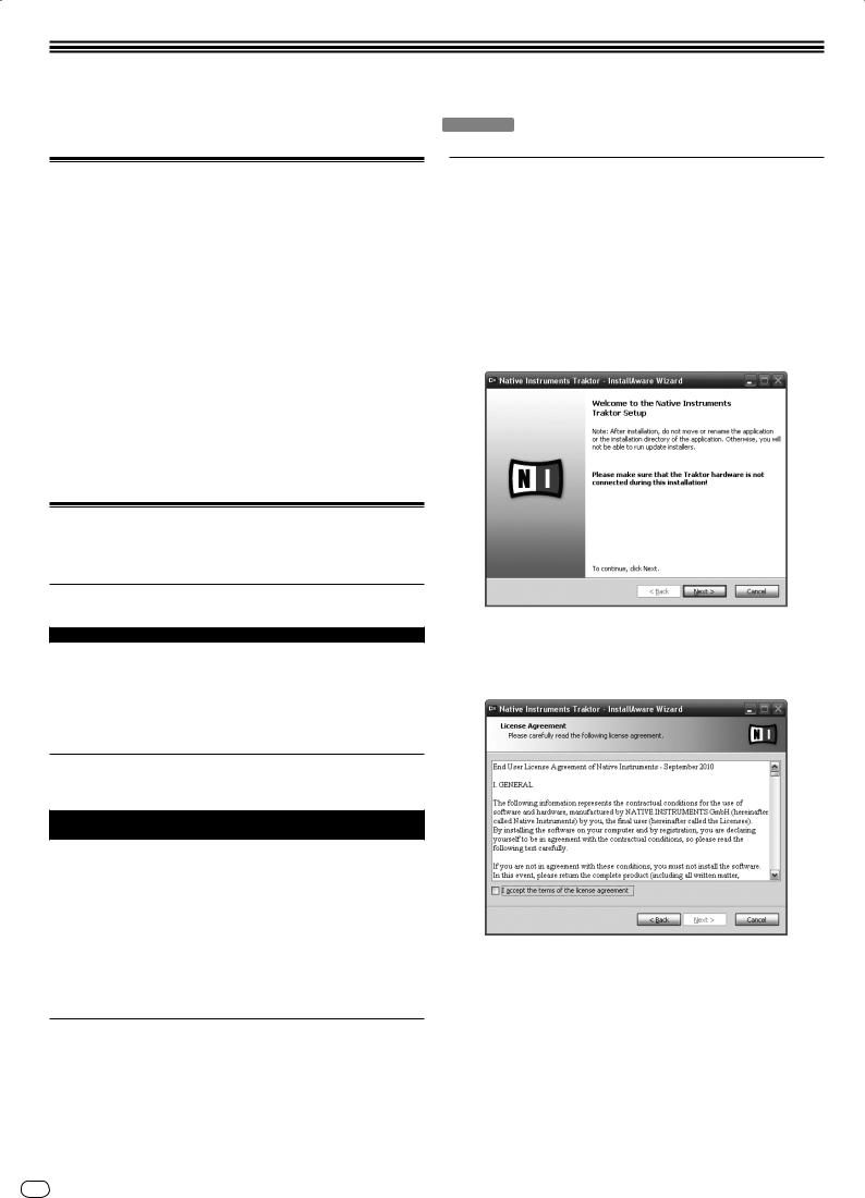
The TRAKTOR installer is launched.
4Once the TRAKTOR installer is launched, click [Next].
—To return to the previous screen: Click [Back].
—To cancel installation: Click [Cancel].
5 Read the contents of the [License Agreement] carefully, and if you agree, check [I accept the terms of the license agreement], then click [Next].
If you do not agree to the terms of the [License Agreement], click [Cancel] to cancel installation.
6 Choose the type of TRAKTOR installation, then click [Next].
Normally install all options, including [Controller Editor] and [Service Center].
7 Choose where to install TRAKTOR, then click [Next].
To choose the normal place of installation, simply click [Next].
To install in a different location, click [Change...], choose the place of installation, then click [Next].
8 Select the Native Instruments hardware driver, then click [Next].
Check the check box for your hardware.
9To install the Traktor Kontrol X1 driver, check the check box, then click [Next].
10When the following screen appears, click [Next].
Installation begins.
The installation completed screen appears once installation is completed.
11 Click [Finish].
This completes the installation procedure.
Installation Procedure (Macintosh)
1 Insert the included TRAKTOR SCRATCH DUO 2 software DVD-ROM into the computer’s DVD drive.
The [Traktor] icon appears on the screen.
2 Double-click the [Traktor] icon.
The contents of the DVD-ROM are displayed.
3 Double-click [Traktor 2 2.0.x Installer Mac.mpkg].
The TRAKTOR installer is launched.
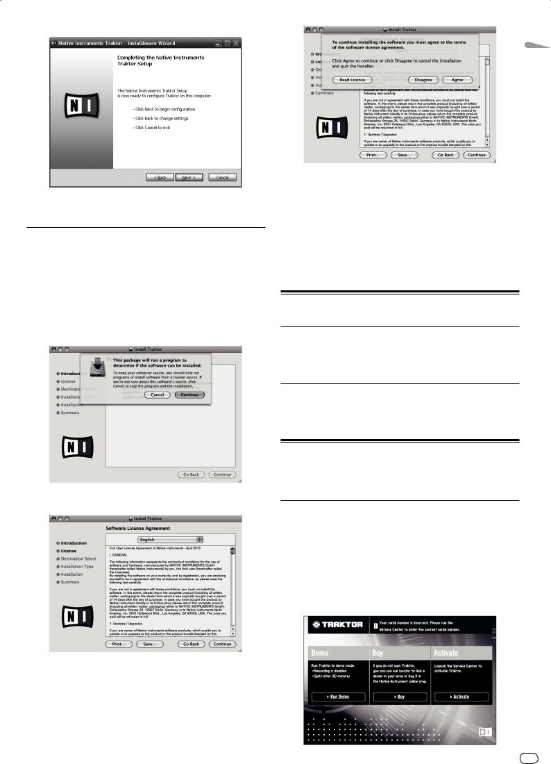
4 Once the TRAKTOR installer is launched, click [Continue].
5 Read the contents of the license agreement carefully, then click [Continue].
6 If you agree to the contents of the usage agreement, click [Agree].
If you do not agree to the contents of the usage agreement, click [Disagree] to cancel installation.
English
7 Select the Native Instruments hardware driver, then click [Continue].
Check the check box for your hardware.
8 Choose where to install TRAKTOR, then click [Install].
To choose the normal place of installation, simply click [Install].
To install in a different location, click [Change Install Location...], choose the place of installation, then click [Install].
Installation begins.
The installation completed screen appears once installation is completed.
9 Click [Restart].
This completes the installation procedure.
Launching TRAKTOR
For Windows
From the Windows [Start] menu, open [All Programs] > [Native Instruments] > [Traktor 2], then click the [Traktor 2] icon.
For Mac OS X
In Finder, open the [Application] folder, next open [Native Instruments] > [Traktor 2], then double-click the [Traktor 2] icon.
Performing product activation
To use TRAKTOR SCRATCH DUO 2, first perform product activation (referred to simply as “activation” below) using Native Instruments SERVICE CENTER (referred to simply as “SERVICE CENTER” below).
Launching the SERVICE CENTER
There are three ways to do this:
—Launching from the dialog displayed when TRAKTOR is started up
—Launching from the TRAKTOR [Help] menu
—Launching SERVICE CENTER directly
To launch from the dialog displayed when TRAKTOR is started up
1 Launching TRAKTOR
The screen below appears.
En 7
!This dialog is displayed each time TRAKTOR is launched until the license is acquired from SERVICE CENTER.
2Select the method for acquiring the license, then click.
—[Run Demo]: Launch TRAKTOR in the demo mode.
—[Buy]: Purchase TRAKTOR from the Native Instruments online shop.
—[Activate]: Acquire the license immediately from the SERVICE CENTER.
To launch from the TRAKTOR [Help] menu
From the TRAKTOR [Help] menu, click [Launch Service Center].
To launch the SERVICE CENTER directly
For Windows
From the Windows [Start] menu, click the [Native Instruments] > [Service Center] > [Service Center] icons.
For Mac OS X
In Finder, open the [Application] folder, then double-click the [Service Center] > [Service Center] icons.
Activation procedure
—Online activation: When your computer is connected to the Internet
—Offline activation: When your computer is not connected to the Internet
Online activation
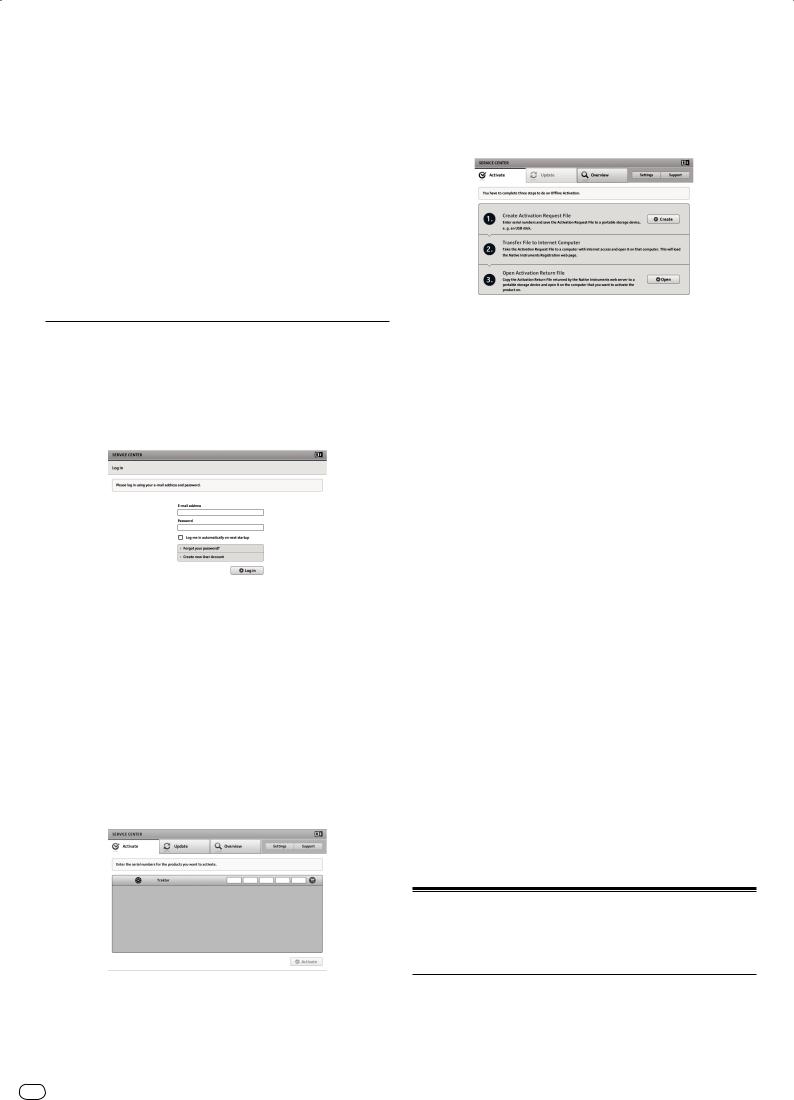
1 Launch the SERVICE CENTER.
The log-in screen is displayed.
2 Input your e-mail address and password, then click [Log in].
!When logging in for the first time, you must create a new user account.
When [Create new User Account] is clicked, the new user account registration screen appears.
Input the required items (e-mail address, first and last names), select your country/region, then click [Next].
When the registration information confirmation screen appears, check the contents, then click [OK].
A password is sent to the e-mail address input on the form. Return to the log-in screen and log in.
!The personal information input when registering a new user account may be collected, processed and used based on the privacy policy on the Native Instruments website.
Pioneer Corporation does not collect, process or use this personal information.
3 Input the serial number indicated on the package of the TRAKTOR SCRATCH DUO 2 software DVD-ROM, then click [Activate].
With this procedure, a second computer that can be connected to the Internet is required.
1Launch the SERVICE CENTER on the computer on which TRAKTOR SCRATCH DUO 2 is to be installed.
2Click [Offline] at
[Continue without connecting to the internet].
3 Click [Create] at [Create Activation Request File].
4 Input the serial number indicated on the package of the TRAKTOR SCRATCH DUO 2 software DVD-ROM, then click [Create].
A launch request file is created. Save this file on a USB device, etc.
5Connect the USB device on which the launch request file is saved to the computer that can be connected to the Internet.
6Double-click the launch request file on the computer that can be connected to the Internet.
The web browser is launched.
7Once the product activation screen appears, click [Send].
8Input your e-mail address and password, then click [SUBMIT].
!When logging in for the first time, you must create a new user account.
When [No - I do not have an NI account.] is checked and [SUBMIT] is clicked, the new user account registration screen appears.
Input the required items (e-mail address, first and last names, street address, city and postal code), select your country/region, then click [NEXT].
When a survey screen appears, select answers to the various questions, then click [SUBMIT].
A password is sent to the e-mail address input on the form. Return to the log-in screen and log in.
!The personal information input when registering a new user account may be collected, processed and used based on the privacy policy on the Native Instruments website.
Pioneer Corporation does not collect, process or use this personal information.
9When the [Service Center Activation Page] appears, click [NEXT].
10Check that [Product] is [TRAKTOR SCRATCH DUO 2] and
[Status] is [OK], then click [NEXT].
A launch return file is created. Save this file on a USB device, etc.
11Launch the SERVICE CENTER on the computer on which TRAKTOR SCRATCH DUO 2 is to be installed.
12Click [Offline] at
[Continue without connecting to the internet].
13 Click [Open] at [Open Activation Return File].
The launch return file is loaded.
14 Check in the SERVICE CENTER that product activation has completed.
Installing the driver software
This driver software is designed exclusively for inputting and outputting sound from the computer. To use this unit connected to a computer on which a Windows or Mac OS is installed, first install this driver software on the computer.
4 Once the product license registration successful screen appears, click [Exit].
Offline activation
To activate TRAKTOR SCRATCH DUO 2 installed on a computer that is not connected to the Internet, use SERVICE CENTER in the offline mode.
8 En
Software end user license agreement
This Software End User License Agreement (“Agreement”) is between you (both the individual installing the Program and any single legal entity for which the individual is acting) (“You” or “Your”) and PIONEER CORPORATION (“Pioneer”).
TAKING ANY STEP TO SET UP OR INSTALL THE PROGRAM MEANS THAT YOU ACCEPT ALL OF THE TERMS OF THIS LICENSE AGREEMENT. PERMISSION TO DOWNLOAD AND/OR USE THE PROGRAM IS EXPRESSLY CONDITIONED ON

YOUR FOLLOWING THESE TERMS. WRITTEN OR ELECTRONIC APPROVAL IS NOT REQUIRED TO MAKE THIS AGREEMENT VALID AND ENFORCEABLE. IF YOU DO NOT AGREE TO ALL OF THE TERMS OF THIS AGREEMENT, YOU ARE NOT AUTHORIZED TO USE THE PROGRAM AND MUST STOP INSTALLING IT OR UNINSTALL IT, AS APPLICABLE.
1Definitions
1“Documentation” means written documentation, specifications and help content made generally available by Pioneer to aid in installing and using the Program.
2“Program” means all or any part of Pioneer’s software licensed to You by Pioneer under this Agreement.
2Program license
1Limited License. Subject to this Agreement’s restrictions, Pioneer grants to You a limited, non-exclusive, nontransferable, license (without the right to sublicense):
a To install a single copy of the Program on the hard disk drive of Your computer, to use the Program only for Your personal purpose complying with this Agreement and the Documentation (“Authorized Use”);
b To use the Documentation in support of Your Authorized Use; and
c To make one copy of the Program solely for backup purposes, provided that all titles and trademark, copyright and restricted rights notices are reproduced on the copy.
2Restrictions. You will not copy or use the Program or Documentation except as expressly permitted by this Agreement. You will not transfer, sublicense, rent, lease or lend the Program, or use it for third-party training, commercial time-sharing or service bureau use. You will not Yourself or through any third party modify, reverse engineer, disassemble or decompile the Program, except to the extent expressly permitted by applicable law, and then only after You have notified Pioneer in writing of Your intended activities. You will not use the Program on multiple processors without Pioneer’s prior written consent.
3Ownership. Pioneer or its licensor retains all right, title and interest in and to all patent, copyright, trademark, trade secret and other intellectual property rights in the Program and Documentation, and any derivative works thereof. You do not acquire any other rights, express or implied, beyond the limited license set forth in this Agreement.
4No Support. Pioneer has no obligation to provide support, maintenance, upgrades, modifications or new releases for the Program or Documentation under this Agreement.
3Warranty disclaimer
THE PROGRAM AND DOCUMENTATION ARE PROVIDED “AS IS” WITHOUT ANY REPRESENTATIONS OR WARRANTIES, AND YOU AGREE TO USE THEM AT YOUR SOLE RISK. TO THE FULLEST EXTENT PERMISSIBLE BY LAW, PIONEER EXPRESSLY DISCLAIMS ALL WARRANTIES OF ANY KIND WITH RESPECT TO THE PROGRAM AND DOCUMENTATION, WHETHER EXPRESS, IMPLIED, STATUTORY, OR ARISING OUT OF COURSE OF PERFORMANCE, COURSE OF DEALING OR USAGE OF TRADE, INCLUDING ANY WARRANTIES OF MERCHANTABILITY, FITNESS FOR A PARTICULAR PURPOSE, SATISFACTORY QUALITY, ACCURACY, TITLE OR NON-INFRINGEMENT.
4 Damages and remedies for breach
You agree that any breach of this Agreement’s restrictions would cause Pioneer irreparable harm for which money damages alone would be inadequate. In addition to damages and any other remedies to which Pioneer may be entitled, You agree that Pioneer may seek injunctive relief to prevent the actual, threatened or continued breach of this Agreement.
5 Termination
Pioneer may terminate this Agreement at any time upon Your breach of any provision. If this Agreement is terminated, You will stop using the Program, permanently delete it from the computer where it resides, and destroy all copies of the Program and Documentation in Your possession, confirming to Pioneer in writing that You have done so. Sections 2.2, 2.3, 2.4, 3, 4, 5 and 6 will continue in effect after this Agreement’s termination.
6General terms
1Limitation of Liability. In no event will Pioneer or its subsidiaries be liable in connection with this Agreement or its subject matter, under any theory of liability, for any indirect, incidental, special, consequential or punitive damages, or damages for lost profits, revenue, business, savings, data, use, or cost of substitute procurement, even if advised of the possibility of such damages or
if such damages are foreseeable. In no event will Pioneer’s liability for all damages exceed the amounts actually paid by You to Pioneer or its subsidiaries for the Program. The parties acknowledge that the liability limits and risk allocation in this Agreement are reflected in the Program price and are essential elements of the bargain between the parties, without which Pioneer would not have provided the Program or entered into this Agreement.
2The limitations or exclusions of warranties and liability contained in this Agreement do not affect or prejudice Your statutory rights as consumer and shall apply to You only to the extent such limitations or exclusions are permitted under the laws of the jurisdiction where You are located.
3Severability and Waiver. If any provision of this Agreement is held to be illegal, invalid or otherwise unenforceable, that provision will be enforced to the extent possible or, if incapable of enforcement, deemed to be severed and deleted from this Agreement, and the remainder will continue in full
force and effect. The waiver by either party of any default or breach of this |
|
Agreement will not waive any other or subsequent default or breach. |
|
4 No Assignment. You may not assign, sell, transfer, delegate or otherwise |
English |
dispose of this Agreement or any rights or obligations under it, whether vol- |
|
You will be null and void. Subject to the foregoing, this Agreement will be |
|
untarily or involuntarily, by operation of law or otherwise, without Pioneer’s |
|
prior written consent. Any purported assignment, transfer or delegation by |
|
binding upon and will inure to the benefit of the parties and their respective |
|
successors and assigns. |
|
5Entire Agreement. This Agreement constitutes the entire agreement between the parties and supersedes all prior or contemporaneous agreements or representations, whether written or oral, concerning its subject matter. This Agreement may not be modified or amended without Pioneer’s prior and express written consent, and no other act, document, usage or custom will be deemed to amend or modify this Agreement.
6You agree that this Agreement shall be governed and construed by and under the laws of Japan.
Before installing the driver software
!Read Software end user license agreement carefully.
!Turn off this unit’s power switch, then disconnect the USB cable connecting this unit and the computer.
!If any other programs are running on the computer, quit them.
!To install or uninstall the driver software, you need to be authorized by the administrator of your computer. Log on as the administrator of your computer before proceeding with the installation.
!If you connect this unit to your computer without installing the driver software first, an error may occur on your computer depending on the system environment.
!If installation of the driver software is interrupted after it has started, start the installation procedure over again from the beginning.
!The provided CD-ROM includes installation programs in the following 12 languages.
English, French, German, Italian, Dutch, Spanish, Portuguese, Russian, Chinese (simplified characters), Chinese (traditional characters), Korean, Japanese. When using an operating system in any language besides the ones listed above, select [English] during the installation procedure.
Supported operating systems
Windows® 7 Home Premium/Professional/Ultimate |
32-bit version |
1 |
|
64-bit version |
1 |
||
|
|||
Windows Vista® Home Basic/Home Premium/Business/ |
32-bit version |
1 |
|
Ultimate |
64-bit version |
1 |
|
Windows® XP Home Edition/Professional (SP2 or later) |
32-bit version |
1 |
|
Mac OS X 10.4.8 or later |
32-bit version |
1 |
|
Mac OS X 10.6 |
32-bit version |
1 |
|
64-bit version |
1 |
||
|
!Windows® XP Professional x64 Edition is not supported.
Installation Procedure (Windows)
1Insert the included driver software CD-ROM into the computer’s DVD drive.
2Once the CD-ROM’s menu is displayed, double-click [DJMT1_X.XXX.exe].
3Proceed with installation according to the instructions on the screen.
If [Windows Security] appears on the screen while the installation is in progress, click [Install this driver software anyway] and continue with the installation.
!When installing on Windows XP
If [Hardware Installation] appears on the screen while the installation is in progress, click [Continue Anyway] and continue with the installation.
!When the installation program is completed, a completion message appears.
Installation Procedure (Macintosh)
1Insert the included driver software CD-ROM into the computer’s DVD drive.
2Once the CD-ROM’s menu is displayed, double-click [DJMT1AudioDriver.dmg].
3Double-click [DJM-T1AudioDriver.pkg].
4Proceed with installation according to the instructions on the screen.
En 9

Connecting the input/output terminals
Be sure to turn off the power and unplug the power cord from the power outlet whenever making or changing connections.
Connect the power cord after all the connections between devices have been completed.
Be sure to use the included power cord.
Refer to the operating instructions for the component to be connected.
!When creating a DVS (Digital Vinyl System) combining a computer, audio interface, etc., be careful in connecting the audio interface to this unit’s input terminals and in the settings of the input selector switches.
Also refer to the operating instructions of the DJ software and audio interface.
Rear panel, front panel
Analog player |
DJ player |
Analog player |
DJ player |
||||||||||
|
|
|
|
|
|
|
|
|
|
|
|
|
|
|
|
|
|
|
|
|
|
|
|
|
|
|
|
|
|
|
|
|
|
|
|
|
|
|
|
|
|
|
|
|
|
|
|
|
|
|
|
|
|
|
|
|
|
|
|
|
|
|
|
|
|
|
|
|
|
|
|
|
|
|
|
|
|
|
|
|
|
|
|
1 |
|
CH 2 |
|
|
CH 1 |
|
|
5 |
|||
PHONO |
CD |
|
|
PHONO |
CD |
|
|
||||
POWER |
|
|
|
|
6 |
||||||
L |
L |
L |
|
|
L |
L |
L |
|
|
||
OFF |
|
4 |
|
|
|
|
|
||||
ON |
2 |
3 |
|
2 |
3 |
|
|
|
|||
|
|
|
|
|
|
||||||
c |
R |
R |
R |
IGNAL |
|
R |
R |
R |
|
|
7 |
|
|
MASTER 1 |
|
|
|
|
|
||||
|
|
|
|
|
|
|
|
|
|||
AC IN 220 - 240V |
|
BOOTH |
R |
L |
1.GND 2.HOT |
MASTER 2 |
USB |
||||
|
R |
TRS L |
a |
|
MASTER |
R |
8 |
L |
|
||
|
|
b |
|
|
|
|
|||||
|
|
|
|
|
|
3.COL |
|
|
|
|
|
|
|
|
|
|
|
ATT. |
|
|
|
|
|
|
|
|
|
|
|
-6 dB |
0 dB |
R |
|
L |
|
|
|
|
|
|
|
9 |
|
|
|
|
|
To power outlet |
Power amplifier |
|
|
|
|
|
|
|
|
||
(for booth monitor) |
Power amplifier |
Power amplifier |
Computers |
||||||||
Headphones
PHONES
d
e
f
L R
 AUX
AUX 
Portable Microphones audio device
1 POWER button
Turns this unit’s power on and off.
2 PHONO terminals
Connect to a phono level (MM cartridge) output device. Do not input line level signals.
To connect a device to the [PHONO] terminals, remove the short-circuit pin plug inserted in the terminals.
Insert this short-circuit pin plug into the [PHONO] terminals when nothing is connected to them to cut external noise.
3 CD terminals
Connect to a DJ player or a line level output component.
4 SIGNAL GND terminal
Connect an analog player’s ground wire here. This helps reduce noise when the analog player is connected.
5 Cord hook
Hook the USB cable here.
!The sound will be interrupted if the USB cable is disconnected during playback.
6Kensington security slot
7USB port
Connect to a computer.
!Connect this unit and the computer directly using the included USB cable.
!A USB hub cannot be used.
8 MASTER2 terminals
Connect to a power amplifier, etc.
9 MASTER ATT.
Sets the attenuation level of the sound output from the [MASTER1] and [MASTER2] terminals.
When set to [–6 dB], the audio level output from the [MASTER1] and [MASTER2] terminals is decreased by half.
A MASTER1 terminals
Connect to a power amplifier, etc.
B BOOTH terminals (page 17)
Output terminals for a booth monitor, compatible with balanced or unbalanced output for a TRS connector.
!The sound will be distorted if the level is raised too high when using unbalanced outputs.
C AC IN
Connect to a power outlet using the included power cord. Wait until all connections between the equipment are completed before connecting the power cord. Be sure to use the included power cord.
D PHONES terminal (page 16)
Connect headphones here.
E MIC terminal (page 22)
Connect a microphone here.
F AUX IN terminals (page 22)
Connect to the output terminal of an external device (sampler, portable audio device, etc.)
Cord hook
The USB cable is fastened in place by catching it on the cord hook. This prevents the USB cable from being pulled accidentally and its plug getting disconnected from the port.
!The sound will be interrupted if the USB cable is disconnected during playback.
TER 2 |
USB |
L
USB cable
10 En
Setting this unit
Be sure to install this unit’s exclusive driver software before connecting this unit and the a computer by USB cable.
1 Switch the [CD, PHONO, USB] input selector switch.
Set it to [USB].
CD PHONO USB
Playing tracks
1 Set the CONTROL CD in the DJ player.
!To use an analog player, set the CONTROL VINYL.
2 Set TRAKTOR to the [Scratch Control] mode.
TRAKTOR
Check that the right section of the [d] button in TRAKTOR is displayed as shown below.
2 Connect this unit to your computer via a USB cable.
This unit functions as an audio device conforming to the ASIO standards.
!This operation does not work with computers that do not support USB 2.0.
!When using applications supporting ASIO, [USB 1/2], [USB 3/4] and [USB 5/6] can be used as inputs.
!The computer’s recommended operating environment depends on the DJ application. Be sure to check the recommended operating environment for the DJ application you are using.
!When another USB audio device is connected to the computer at the same time, it may not operate or be recognized normally.
We recommend only connecting the computer and this unit.
!When connecting the computer and this unit, we recommend connecting directly to this unit’s USB port.
3 Press [POWER] button.
Turn on the power of this unit.
!The message [Installing device driver software] may appear when this unit is first connected to the computer or when it is connected to a different USB port on the computer. Wait a while until the message [Your devices are ready for use] appears.
!When installing on Windows XP
—[Can Windows connect to Windows Update to search for software?] may appear while the installation is in progress. Select [No, not this time], then click [Next] to continue installation.
—[What do you want the wizard to do?] may appear while the installation is in progress. Select [Install the software automatically (Recommended)], then click [Next] to continue installation.
—If [Windows Security] appears on the screen while the installation is in progress, click [Install this driver software anyway] and continue with the installation.
Changing the setting utility’s settings
1Displaying the setting utility
!For Windows
Click [Start] menu > [All Programs] > [Pioneer] > [DJM-T1] > [DJM-T1 Setting Utility].
!For Mac OS X
Click [Macintosh HD] icon > [Application] > [Pioneer] > [DJM-T1] > [DJM-T1 Setting Utility].
2Click the [MIXER OUTPUT] tab.
3Click the [Mixer Audio Output] pull-down menu.
Set as shown below, according to the devices connected to this unit.
|
When using a DJ player |
When using an analog player |
|
|
(CONTROL CD) |
(CONTROL VINYL) |
|
USB 1/2 |
CH1 Timecode CD |
CH1 Timecode PHONO |
|
|
|
|
|
USB 3/4 |
CH2 Timecode CD |
CH2 Timecode PHONO |
|
|
|
|
|
!If [CUE] and [CUP] are displayed, operate the computer to switch TRAKTOR to the [Scratch Control] mode.
3 Press the [f (REL.)] or [CUE (ABS.)] button while pressing the [SHIFT] button.
Select the Relative or Absolute mode.
—Press the [f (REL.)] button while pressing the [SHIFT] button: Switches to the Relative mode.
The Relative mode is a mode that ignores the playback position of the CONTROL CD/CONTROL VINYL.
—Press the [CUE (ABS.)] button while pressing the [SHIFT] button: Switches to the Absolute mode.
The Absolute mode is a mode that reflects the playback position of the CONTROL CD/CONTROL VINYL on the playback position of the track.
4 Turn the rotary selector.
Select the track.
|
PUSH |
BROWSE |
VIEW |
TREE |
FLD OPEN |
5 Press the [LOAD (DUPLICATE)] button.
The selected track is loaded in the deck.
LOAD |
LOAD |
DUPLICATE |
DUPLICATE |
AB
!For detailed instructions on selecting tracks and loading tracks in decks, see
Browse section on page 13.
6 Play the CONTROL CD.
Playback of the track loaded in the TRAKTOR deck begins.
!To use an analog player, play the CONTROL VINYL.
English
En 11

Operation
7
6
4
1
5
3
2 |
1 |
2 |
3 |
MIDI |
|
LOAD |
LOAD |
|
|
DUPLICATE |
DUPLICATE |
ON/OFF |
UTILITY |
A |
B |
CH1 |
CH2 |
DECK A |
|
|
|
|
DECK B |
||
|
|
|
|
|
|
||||
|
|
WAKE UP |
|
|
|
|
|
|
|
|
|
|
CUE |
|
|
|
PUSH |
|
CUE |
|
|
|
|
BROWSE |
|
VIEW |
|
|
|
|
|
REL. |
ABS. |
|
TREE |
FLD OPEN |
REL. |
ABS. |
|
|
SNAP |
|
|
|
|
|
|
|
|
|
|
FX |
ASSIGN |
|
|
|
|
FX |
ASSIGN |
|
QUANTIZE |
FX1 |
FX2 |
SYNC |
|
SYNC |
FX1 |
FX2 |
|
|
FX1 |
|
|||||||
|
|
BEND |
MASTER |
MASTER |
|
BEND |
|||
|
DRY/ WET |
|
|||||||
|
|
|
|
|
|
|
|
||
ON |
|
|
1 |
MASTER |
2 |
|
|
||
|
|
|
OVER |
OVER |
|
|
|||
|
|
CD |
USB |
|
9 |
|
9 |
CD |
USB |
GROUP |
|
|
|
|
|||||
PHONO |
|
5 |
|
5 |
PHONO |
||||
/ SINGLE |
|
|
|||||||
|
|
1 |
TRIM |
|
3 |
|
3 |
|
TRIM |
|
|
|
|
1 |
|
1 |
|
||
|
|
|
|
|
|
|
|
||
1 |
|
|
|
|
0 |
|
0 |
|
|
|
|
|
|
-1 |
|
-1 |
|
|
|
|
|
|
|
|
|
|
|
||
LFO |
|
|
9 |
|
-3 |
|
-3 |
|
9 |
FX |
2 |
HI |
|
-6 |
|
-6 |
|
HI |
|
SELECT |
|
-9 |
|
-9 |
|
||||
|
|
|
|
|
|
|
|
||
2 |
|
|
|
|
-15 |
-15 |
|
|
|
|
|
|
|
-24 |
-24 |
|
|
||
LFO |
|
|
|
|
dB |
|
dB |
|
|
|
|
6 |
HEADPHONES |
|
6 |
||||
|
|
|
|
||||||
|
|
3 |
MID |
|
MIXING |
|
MID |
||
3 |
|
|
|
|
|
|
|
|
|
LFO |
|
|
6 |
|
|
|
|
|
6 |
|
DECK A /C |
|
|
CUE |
|
MASTER |
|
||
|
|
LOW |
|
LEVEL |
|
|
LOW |
||
LOOP |
AUTO LOOP |
SAMPLE |
6 |
|
|
|
0 |
|
6 |
MOVE |
LEVEL |
|
|
|
|
||||
SELECT |
CUE |
SHIFT |
CUE |
CROSS.F. CONTROL |
TAP |
LOCK |
TAP |
HOT CUE SAMPLER
DEL DEL
1 |
10 |
|
10 |
|
9 |
|
9 |
|
8 |
|
8 |
|
7 |
|
7 |
|
6 |
|
6 |
2 |
5 |
|
5 |
4 |
|
4 |
|
|
|
||
|
3 |
|
3 |
|
2 |
|
2 |
|
1 |
|
1 |
3 |
0 |
|
0 |
|
|
|
|
|
|
2 CHANNEL TRAKTOR MIXER |
|
|
CH 1 |
DJM -T1 |
CH 2 |
4
POWER 
MASTER
0 |
BOOTH MONITOR
0 |
FX2 |
DRY/ WET
ON
GROUP / SINGLE
1
1
LFO
FX
2 SELECT
2
LFO
3
3
LFO
DECK B/D
SAMPLE |
AUTO LOOP |
LOOP |
LEVEL |
MOVE |
SELECT
CROSS.F. CONTROL
SAMPLER HOT CUE
DEL DEL
1
2
3
4


 FEELING ADJ.
ACTIVE PLAY MODE |
PLAY MODE ACTIVE |
CROSS F.
REVERSE
PHONES
PHONES |
CROSS F. CURVE |
|
THRU |
||
|
CROSS F. REVERSE
ON
 OFF
OFF
3
4
5
3
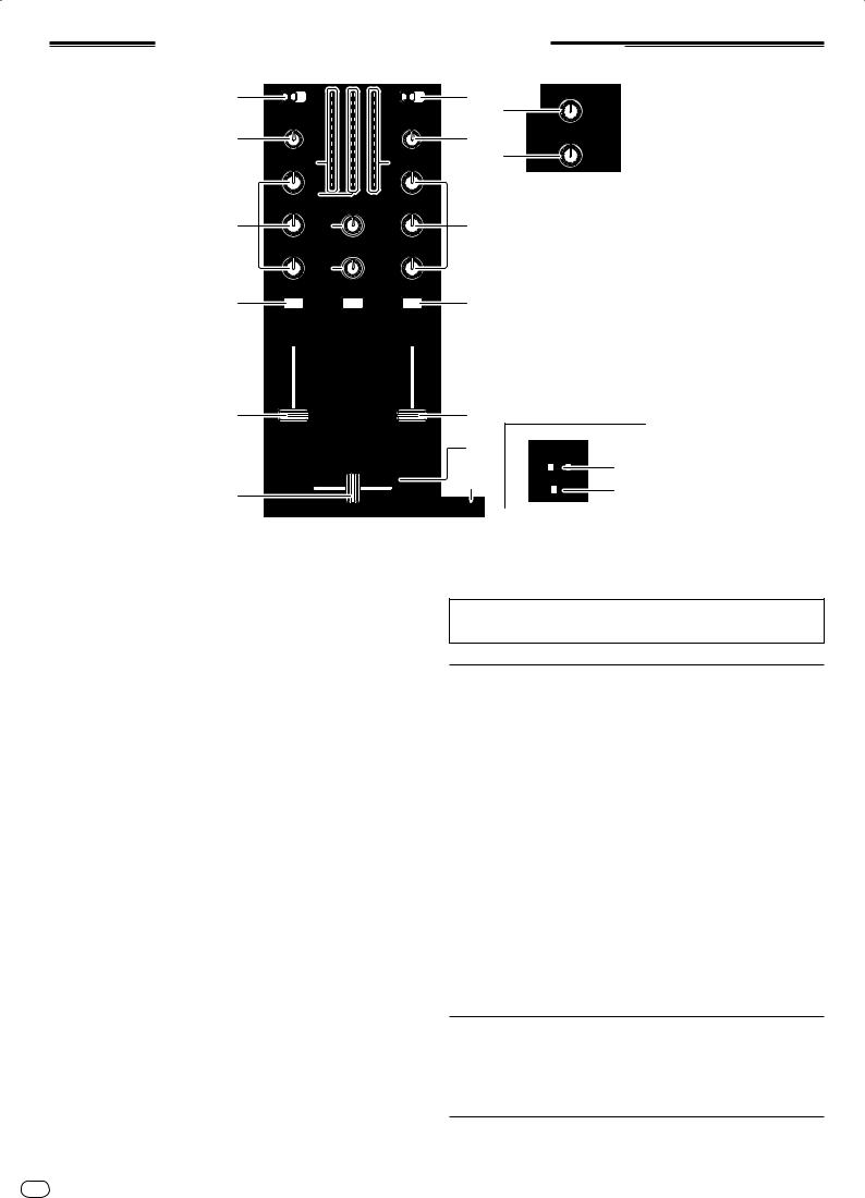
1Browse section (page 13)
2Transport section (page 14)
3Mixer section (page 16)
4Effect section (page 18)
5Hot cue/sampler section (page 20)
6Global section (page 22)
7MIDI section (page 22)
8MIC/AUX section (page 22)
|
|
MIC OFF AUX |
MIC |
L AUX R |
INPUT SELECT |
0 |
12 |
12 |
12 |
12 |
8 |
LEVEL |
LOW |
|
EQ |
HI |
|
1SHIFT button
!Press another button while pressing the [SHIFT] button:
The other function assigned to the button that is pressed is called out.
!Press the [SHIFT] button twice:
The [SHIFT] button is locked in the pressed status. To unlock it, press the [SHIFT] button again.
2UTILITY (WAKE UP) button
!Press:
The auto standby mode is canceled (page 25).
!Press for over 1 second:
Switches to the mode for changing this unit’s settings (page 25).
3POWER indicator
Lights when this unit’s power is on.
12 En
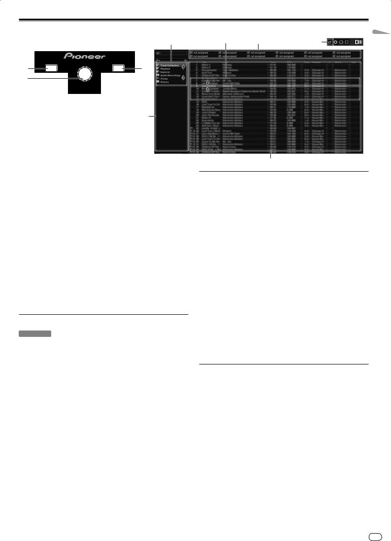
Browse section
(SHIFT)+2
|
|
LOAD |
|
|
LOAD |
|
|
DUPLICATE |
|
|
DUPLICATE |
||
1 |
|
A |
|
|
B |
1 |
2 |
DECK A |
|
|
DECK B |
||
|
|
REL. |
|
PUSH |
|
REL. |
|
|
|
BROWSE |
VIEW |
|
|
|
CUE |
ABS. |
TREE |
FLD OPEN |
CUE |
ABS. |
1
1LOAD (DUPLICATE) button
!Press:
The track selected with the cursor is loaded in the respective deck.
![SHIFT] + press:
The track loaded in the one deck is copied and loaded into the other deck.
2Rotary selector
!Turn:
The cursor in the [TRACK] area moves.
!Press:
The [BROWSE] area’s magnified display turns on and off.
![SHIFT] + turn:
The cursor in the [TREE] area moves.
![SHIFT] + press:
The folder opens/closes.
*Description of areas
—[TREE] area: Section 1 on the diagram above is called the [TREE] area.
—[TRACK] area: Section 2 on the diagram above is called the [TRACK] area.
—[FAVORITES] area: Section 3 on the diagram above is called the [FAVORITES] area.
—[BROWSE] area: Sections 1, 2 and 3 on the diagram above are collectively called the [BROWSE] area.
Importing tracks to TRAKTOR
TRAKTOR
From Explorer or Finder, drag & drop music files or folders containing music files to [Track Collection] in TRAKTOR’s [TREE] area.
!Right-click [Track Collection] (on Mac OS X, click [Track Collection] while pressing the [control] key), then select [Import Music Folders] from the menu. All the music files in your system’s [My Music] or [Music] folder are imported.
Creating playlists
1 Right-click [Playlists] in TRAKTOR’s [TREE] area.
!For Mac OS X, click it while pressing the [control] key.
2From the menu, select [Create Playlist].
3Input the playlist name, then click [OK].
The playlist you have created is displayed at [Playlists].
4 Drag & drop music files to the playlist you have created to add them.
Creating a FAVORITES
Drag and drop a playlist folder to an open slot in the [FAVORITES] area.
2 |
3 |
2 (Press) |
2
Loading tracks to decks
1 Turn the rotary selector while pressing the [SHIFT] button.
Select the playlist or folder.
2 Press the rotary selector while pressing the [SHIFT] button.
The folder opens/closes.
!Items without the [+] mark cannot be opened/closed.
3 Release the [SHIFT] button and turn the rotary selector.
Select the track.
4 Press the [LOAD (DUPLICATE)] button.
The selected track is loaded in the deck.
Playing iTunes music files
If you are managing music files with iTunes, the iTunes library and playlists can be accessed directly with the TRAKTOR browser.
1 Turn the rotary selector while pressing the [SHIFT] button.
Select the [iTunes] folder.
2 Press the rotary selector while pressing the [SHIFT] button.
The folder opens/closes.
3 Browsing the library and playlists in the same way as with iTunes
!The iTunes library and playlists cannot be edited with the TRAKTOR browser.
!When played from the TRAKTOR browser, iTunes music files are automatically imported to the TRAKTOR [Track Collection] list.
Using the duplicate function
This function allows you to easily copy tracks that are loaded in one of the decks onto the other deck.
!The following describes the procedure for copying a track from deck [A] onto deck [B].
1 Select the track, then press the [LOAD (DUPLICATE)] button of the deck [A].
The track is loaded into deck [A].
2 Press the [LOAD (DUPLICATE)] button of the deck [B] while pressing the [SHIFT] button.
The track loaded in deck [A] is copied and loaded into deck [B].
English
En 13
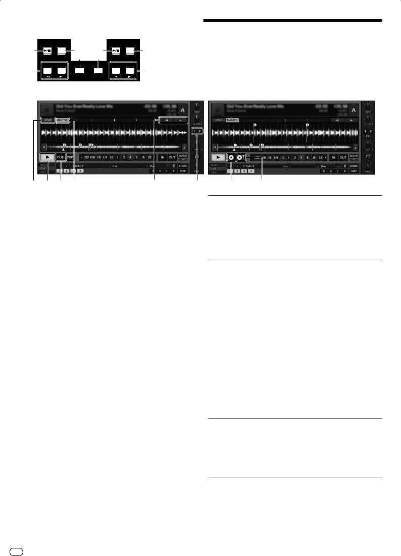
Transport section
|
DECK A |
|
|
DECK B |
|
||
1 |
|
CUE |
2 |
1 |
|
CUE |
2 |
|
|
|
|
PUSH |
|
|
|
|
|
|
BROWSE |
VIEW |
|
|
|
|
|
|
4 |
4 |
|
|
|
|
REL. |
ABS. |
TREE |
FLD OPEN |
REL. |
ABS. |
|
|
FX |
ASSIGN |
|
|
FX |
ASSIGN |
|
3 |
FX1 |
FX2 |
SYNC |
SYNC |
FX1 |
FX2 |
3 |
|
|
BEND |
MASTER |
MASTER |
|
BEND |
|
Internal Playback mode
4 1 2 (SHIFT)+4 |
(SHIFT)+3 |
3 |
1f (REL.) button
!Press:
Use this to play/pause tracks.
![SHIFT] + press:
The TRAKTOR playback tracking mode switches to the Relative mode. The Relative mode is a mode that ignores the playback position of the CONTROL CD/CONTROL VINYL.
2CUE (ABS.) button
While pausing
!Press:
A cue point is set at the paused position.
—When the [SNAP] function of TRAKTOR is off:
The cue point is set to the currently paused position, regardless of the [Beat Grid].
—When the [SNAP] function of TRAKTOR is on:
The cue point is set to the same position as the nearest [Beat Grid].
During playback
!Press:
Playback returns to the set cue point and cues, and playback pauses (back cue).
If the [CUE (ABS.)] button is pressed and held in after returning to the cue point, playback continues as long as the button is held.
![SHIFT] + press:
The TRAKTOR playback tracking mode switches to the Absolute mode. The Absolute mode is a mode that reflects the playback position of the CONTROL CD/CONTROL VINYL on the playback position of the track.
3FX ASSIGN (s BEND t) button
!Press the [FX 1] button:
TRAKTOR effect unit [FX 1] is assigned to the deck whose button is pressed.
!Press the [FX 2] button:
TRAKTOR effect unit [FX 2] is assigned to the deck whose button is pressed. * When using TRAKTOR SCRATCH DUO 2, the assignment is fixed: [FX 1]
to deck [A], [FX 2] to deck [B].
If you upgrade to TRAKTOR SCRATCH PRO 2, [FX 1] and [FX 2] can be assigned freely to the desired deck.
!Press the [SHIFT] + [FX 1] buttons:
The track’s playing speed temporarily slows down.
!Press the [SHIFT] + [FX 2] buttons:
The track’s playing speed temporarily speeds up.
4SYNC (MASTER) button
!Press:
The [BPM] and [Beat Grid] of the track for the deck whose button was pressed are synchronized to the master for synchronization.
![SHIFT] + press:
The deck whose button was pressed is set as the master for synchronization.
Scratch Control mode
(SHIFT)+1 (SHIFT)+2
Playback
Press the [f (REL.)] button.
Pausing
During playback, press the [f(REL.)] button.
Set the cue
1 During playback, press the [f(REL.)] button.
Playback is paused.
2 Press the [CUE (ABS.)] button.
Cue point [a] is set at the position at which playback was paused. No sound is output at this time.
!When a new Cue Point is set, the previously set Cue Point is deleted.
Returning to Cue Point (Back Cue)
During playback, press the [CUE (ABS.)] button.
The set immediately returns to the currently set cue point and pauses.
!When the [f (REL.)] button is pressed, playback starts from the cue point.
Checking Cue Point (Cue Point Sampler)
Press and hold the [CUE (ABS.)] button after returning to the cue point.
Playback starts from the set cue point.
Playback continues while the [CUE (ABS.)] button is pressed.
Bending the pitch
Press the [FX 1] or [FX 2] button while pressing the [SHIFT] button.
—Press the [SHIFT] + [FX 1] buttons:
The track’s playing speed temporarily slows down.
—Press the [SHIFT] + [FX 2] buttons:
The track’s playing speed temporarily speeds up.
Synchronizing the playing speed with other decks (beat sync)
1 Press the [SYNC (MASTER)] button while pressing the [SHIFT] button on the currently playing deck.
The deck whose button was pressed is set as the master for synchronization.
14 En
2 Press the [SYNC (MASTER)] button on the deck not set as the master for synchronization.
The [BPM] and [Beat Grid] of the track for the deck not set as the master for synchronization are synchronized to the [BPM] and [Beat Grid] of the track for the deck set to the master for synchronization.
!For information about setting the master for synchronization, see Setting the master for synchronization on page 15.
!The beat sync function may not operate properly in the following cases.
—When the loop length is under 1 beat.
—When the [BPM] of the track for the deck set as the master for synchronization is out of the adjustable tempo range of the track for the deck to be synchronized.
—When the track has not been analyzed.
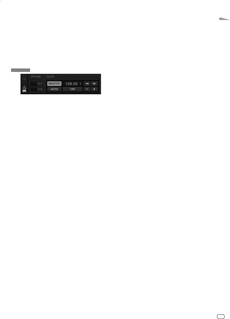
Setting the master for synchronization
TRAKTOR
Click [ ].
].
The master for synchronization can be selected from one of the two types below.
—[MASTER]: The BPM value input by the user or the BPM value set by tapping is set as the master.
—[AUTO]: The master is set automatically. When two decks are playing and the deck set as the master is paused, the other deck is automatically set as the master.
!When using TRAKTOR SCRATCH DUO 2, this is always set to [AUTO]. If you upgrade to TRAKTOR SCRATCH PRO 2, you can select [MASTER] or [AUTO].
English
En 15
Mixer section
3 |
|
1 |
MASTER |
2 |
|
3 |
MASTER |
|
|
|
OVER |
OVER |
|
|
|||
|
|
|
|
|
||||
CD PHONO USB |
|
9 |
9 |
|
CD PHONO USB |
|
1 |
|
|
5 |
5 |
|
|
||||
TRIM |
|
|
3 |
3 |
|
TRIM |
1 |
0 |
|
|
1 |
1 |
|
|
|||
|
|
|
|
|
|
|||
|
|
|
|
|
|
BOOTH MONITOR |
||
4 |
|
|
0 |
0 |
|
|
4 |
|
|
|
-1 |
-1 |
|
|
|
||
|
|
|
|
|
|
|
||
|
9 |
|
-3 |
-3 |
|
9 |
|
2 |
HI |
9 |
|
-6 |
-6 |
|
9 HI |
2 |
|
|
|
|
-9 |
-9 |
|
|
|
0 |
|
|
|
-15 |
-15 |
|
|
|
|
|
|
|
-24 |
-24 |
|
|
|
|
|
6 a |
|
dB |
dB |
|
|
|
|
|
HEADPHONES |
6 |
|
|
||||
|
MID |
MIXING |
|
MID |
3 |
|
5 |
|
b |
|
|
5 |
|
|
6 |
CUE |
MASTER |
6 |
|
D |
|
LOW |
LEVEL |
|
LOW |
|
|
|
|
c |
|
|
|
|
|
6 |
|
0 |
6 |
SAMPLE |
A |
|
|
LEVEL |
||||
6 |
CUE |
SHIFT |
|
CUE |
6 |
|
|
TAP |
LOCK |
|
TAP |
CRO |
|
SAMP
DE
7
8
10 |
10 |
|
9 |
9 |
|
8 |
8 |
|
7 |
7 |
|
6 |
6 |
|
5 |
5 |
|
4 |
4 |
|
3 |
3 |
|
2 |
2 |
|
1 |
1 |
7 |
0 |
0 |
2 CHANNEL TRAKTOR MIXER
CH 1 DJM -T1 CH 2
d |
CROSS F. CURVE |
|
|
THRU |
|
FEELING ADJ. |
|
f |
PLAYeMO |
CROSS F. REVERSE |
|
ON |
OFF |
|
|
g |
|
CROSS F. |
|
|
REVERSE |
|
|
1 MASTER LEVEL control
Adjusts the audio level output from the [MASTER1] and [MASTER2] terminals.
2 BOOTH MONITOR control
Adjusts the level of audio signals output from the [BOOTH] terminal.
3 CD, PHONO, USB input selector switch
Select the input source of each channel from the components connected to this unit.
—[CD]: Selects the DJ player connected to the [CD] terminals.
—[PHONO]: Selects the analog player connected to the [PHONO] terminals.
—[USB]: Selects the sound of the computer connected to the [USB] port.
4 TRIM control
Adjusts the level of audio signals input in each channel.
5 EQ (HI, MID, LOW) controls
These adjust the sound quality of the respective channels.
These adjust the [HI] (high range), [MID] (middle range) and [LOW] (low range), respectively.
F CROSS F. CURVE (THRU,  ,
, ) selector switch
This switches the crossfader curve characteristics.
G CROSS F. REVERSE switch
Turns the crossfader reverse function on and off.
Do not pull on the channel fader and crossfader knobs with excessive force. The knobs are not designed to be removed. Pulling the knobs strongly may result in damaging the unit.
Outputting sound
Set the volume of the power amplifiers connected to the [MASTER1] and [MASTER2] terminals to a suitable level. Note that loud sound will be produced if the volume is set too high.
1 Switch the [CD, PHONO, USB] input selector switch.
Select the input source of each channel from the components connected to this unit.
6 |
CUE (TAP) button |
2 |
Turn the [TRIM] control. |
|
Press the [CUE (TAP)] button for the channel you want to monitor. |
Adjusts the level of audio signals input in each channel. |
|
7 |
Channel fader |
3 |
Move the channel fader away from you. |
|
Adjusts the level of audio signals output in each channel. |
Adjusts the level of audio signals output in each channel. |
|
8 Crossfader
The sound of the respective channels is output according to the curve characteristics selected with the [CROSS F. CURVE (THRU,  ,
, )] selector switch.
9 Channel Level Indicator
Displays the sound level of the respective channels before passing through the channel faders.
A Master Level Indicator
Displays the audio level output from the [MASTER1] and [MASTER2] terminals.
B HEADPHONES MIXING control
Adjusts the monitor volume balance between the sound of the channel whose [CUE (TAP)] button is pressed and the [MASTER] channel sound.
C HEADPHONES LEVEL control
Adjusts the audio level output from the [PHONES] terminal.
D FEELING ADJ. adjustment hole
This can be used to adjust the crossfader’s operating load.
E CROSS F. REVERSE indicator
Lights when the [CROSS F. REVERSE] switch is on.
4 Set the crossfader.
Switch the channel whose sound is output from the speakers.
—Left edge: The [CH 1] sound is output.
—Center position: The sound of [CH 1] and [CH 2] is mixed and output.
—Right edge: The [CH 2] sound is output.
!This operation is not necessary when the [CROSS F. CURVE (THRU,  ,
, )] selector switch is set to [THRU].
5 Turn the [MASTER LEVEL] control.
Audio signals are output from the [MASTER1] and [MASTER2] terminals.
Adjusting the sound quality
Turn the [EQ (HI, MID, LOW)] controls for the respective channels.
Refer to Specifications on page 30 for the range of sound that can be adjusted by each control.
Monitoring sound with headphones
1 Connect headphones to the [PHONES] terminal.
16 En

2Press the [CUE (TAP)] button for the channel you want to monitor.
3Turn the [HEADPHONES MIXING] control.
Adjusts the monitor volume balance between the sound of the channel whose [CUE (TAP)] button is pressed and the [MASTER] channel sound.
!To monitor only the sound of the [MASTER] channel, turn the [HEADPHONES MIXING] control clockwise from the center position.
4 Turn the [HEADPHONES LEVEL] control.
The sound of the channel whose [CUE (TAP)] button is pressed and the sound of the [MASTER] channel are mixed and output from the headphones.
!Monitoring is canceled when the [CUE (TAP)] button is pressed again.
Select the crossfader curve characteristics.
Switch the [CROSS F. CURVE (THRU,  ,
, )] selector switch.
—[THRU]: Choose this when you do not want to use the crossfader.
—[ ]: Set here for a curve that rises gradually.
—[ ]: Sets an abruptly rising curve. (When the crossfader is moved away from the edge on the [CH 1] side, the sound of the [CH 2] side is output immediately.)
Adjusting the crossfader’s operating load
The load (resistance) when the crossfader is operated can be adjusted using a flathead screwdriver.
!The crossfader’s attenuation curve and the play at the two edges of the fader (the cut lag) can be adjusted. For details, see Changing this unit’s settings on page 25.
1Move the crossfader to the right ([CH 2]) edge.
2Insert the flathead screwdriver into the [FEELING ADJ.] adjustment hole and turn it.
—Turn clockwise: The load decreases (the resistance of fader movement gets weaker).
—Turn counterclockwise: The load increases (the resistance of fader movement gets stronger).
Using the fader reverse function
The crossfader’s operating direction can be reversed by turning the [CROSS F. REVERSE] switch on.
Set the [CROSS F. REVERSE] switch to [ON].
Audio is output from the [BOOTH] terminal
Turn the [BOOTH MONITOR] control.
Adjusts the level of audio signals output from the [BOOTH] terminal.
English
En 17

Effect section
1
2
FX1
DRY/ WET
ON
GROUP / SINGLE
1
1
LFO
FX
SELECT 2
2
LFO
3
3
LFO
Group mode |
4 |
|
3
3 |
(SHIFT)+2 |
2 |
|
(SHIFT)+4 |
|
Single mode
4
3 1 |
(SHIFT)+2 |
2 |
4 |
|
(SHIFT)+3 |
|
|
1 ON (GROUP/SINGLE) button
When using in the [Group] mode
!Press:
Does not function.
![SHIFT] + press:
Switches the effect panel mode. [Group] mode h [Single] mode
When using in the [Single] mode
!Press:
Turns the effect on and off.
![SHIFT] + press:
Switches the effect panel mode. [Group] mode h [Single] mode
—[Group] mode:
Up to three effects can be selected and operated simultaneously per effect panel.
—[Single] mode:
The parameters of the selected effect can be operated in detail.
The [Single] mode cannot be selected with TRAKTOR SCRATCH DUO 2. If you upgrade to TRAKTOR SCRATCH PRO 2, the effect panel can be switched to the [Single] mode.
2 Effect control buttons
When using in the [Group] mode
!Press:
Turns the effects on and off.
![SHIFT] + press:
—When [Generic Controller Mode] is turned on in this unit’s settings: Switches the effect type.
—When [Generic Controller Mode] is turned off in this unit’s settings:
Turns the LFO CONTROL function on and off.
When using in the [Single] mode
!Press the [1] button:
Restores the parameters of all the effects to the base settings.
!Press the [2] or [3] button:
Turns the respective effect on and off. The type of parameter differs according to the effect.
!Press the [SHIFT] + [1] buttons:
—When [Generic Controller Mode] is turned on in this unit’s settings: Switches the effect type.
—When [Generic Controller Mode] is turned off in this unit’s settings: Turns the LFO CONTROL function on and off.
!Press the [SHIFT] + [2] or [SHIFT] + [3] buttons:
—When [Generic Controller Mode] is turned on in this unit’s settings: Does not function.
—When [Generic Controller Mode] is turned off in this unit’s settings: Turns the LFO CONTROL function on and off.
4 Effect control dials
When using in the [Group] mode
!Turn:
Adjusts the degree of the respective effect.
![SHIFT] + turn: Switches the effect type.
*When the LFO CONTROL function is on
—Turn:
Adjusts the cycle for changing the degree of each effects.
—[SHIFT] + turn: Does not function.
When using in the [Single] mode
!Turn:
Adjusts the respective parameter.
![SHIFT] + turn: Does not function.
*When the LFO CONTROL function is on
—Turn:
Adjusts the cycle at which the respective parameter changes.
—[SHIFT] + turn: Does not function.
Using the effect function
!The following section describes the procedure for operating the effect function in the [Group] mode.
1 Press the [FX 1] or [FX 2] button.
The TRAKTOR effect unit is assigned to the deck.
!When using TRAKTOR SCRATCH DUO 2, the assignment is fixed: [FX 1] to deck [A], [FX 2] to deck [B].
If you upgrade to TRAKTOR SCRATCH PRO 2, [FX 1] and [FX 2] can be assigned freely to the desired deck.
2 Turn an effect control dial while pressing the [SHIFT] button.
This selects the type of effect.
!When [Generic Controller Mode] is turned on in this unit’s settings, the type of effect can also be selected by pressing an effect control button while pressing the [SHIFT] button.
3 Turn the effect control dial.
Adjusts the degree of the effect sound.
4 Press the effect control button.
This turns the effect on.
!When the button is pressed again, the effect is turned off.
3 DRY/WET control
When using in the [Group] mode
!Turn:
Adjusts the balance between the effect sound and original sound.
![SHIFT] + turn: Does not function.
When using in the [Single] mode
!Turn:
Adjusts the balance between the effect sound and original sound.
![SHIFT] + turn: Switches the effect type.
18 En
5 Turn the [DRY/WET] control.
Adjust the balance between the effect sound for all of the effects together and the original sound.
Using the LFO CONTROL function
When the LFO CONTROL function is on, the parameter value of the effect sent to TRAKTOR can be changed at the specified speed. This function allows you to create unique effect sounds not possible through manual operation.
With the LFO CONTROL function, effect control buttons [1] – [3] can each be set separately.
!First turn off [Generic Controller Mode] in this unit’s settings. For details, see
Changing this unit’s settings on page 25.

!The following section describes the procedure for operating the LFO CONTROL function in the [Group] mode.
1 Turn an effect control dial while pressing the [SHIFT] button.
This selects the type of effect.
2 Press an effect control button while pressing the [SHIFT] button.
The LFO CONTROL function turns on.
If the effect is off, it turns on simultaneously.
!When the same button is pressed again, the LFO CONTROL function turns off and the effect turns back on.
3 Turn the effect control dial.
Adjusts the cycle for changing the degree of each effects.
4 Turn the [DRY/WET] control.
Adjust the balance between the effect sound for all of the effects together and the original sound.
English
En 19
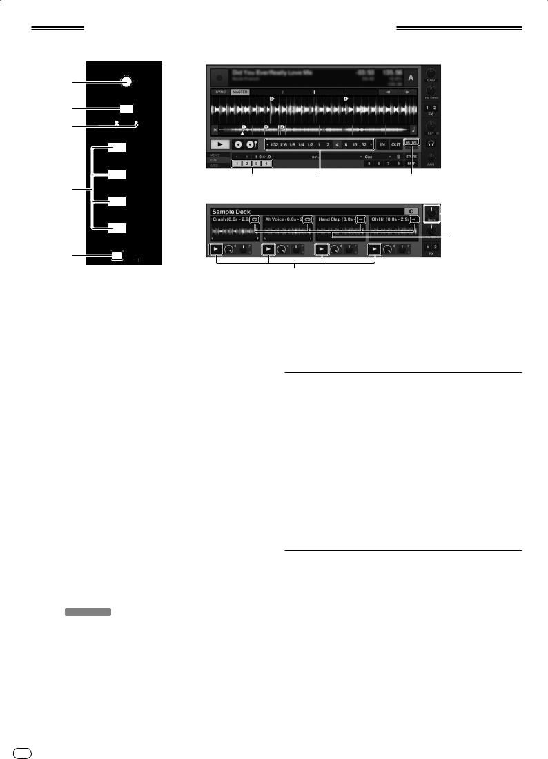
Hot cue/sampler section
HOT CUE mode
DECK A /C
1
LOOP |
AUTO LOOP |
SAMPLE |
MOVE |
LEVEL |
2 |
|
SELECT |
|
CROSS.F. CONTROL |
|
3 |
HOT CUE SAMPLER |
|
|
||
|
DEL |
DEL |
1
2 |
4 |
4
SAMPLER mode
3
4
5 |
ACTIVE PLAY MODE |
1 AUTO LOOP (LOOP MOVE/SAMPLE VOLUME) control
When using with the hot cue function
!Turn:
Changes the loop size.
!Press:
Turns loop playback on and off.
![SHIFT] + turn:
Moves the position of the loop.
![SHIFT] + press:
Does not function.
When using with the sampler function
![SHIFT] + turn:
Adjusts the volume of the sample deck.
![SHIFT] + press:
Resets the volume of the sample deck to the base setting.
2SELECT button
!Press:
Switches the function of the hot cue/sampler section with each press. Hot cue function h Sampler function
![SHIFT] + press:
Turns the CROSS FADER CONTROL function on and off.
3SELECT indicator
Lights or flashes according to the hot cue/sampler section’s function.
—When the hot cue function is set: Lights green.
—When the sampler function is set: Lights orange.
—When the CROSS FADER CONTROL function is on: Flashes green or orange.
4 HOT CUE/SAMPLER button
When using with the hot cue function
!Press:
—When no hot cue is set during playack or while pausing:
A hot cue is set at the position at which the button is pressed.
—When a hot cue is set during playback or while pausing: Calls out the hot cue.
![SHIFT] + press: Deletes the hot cue.
* TRAKTOR
[CUE TYPE] (the type of hot cue) can be changed by clicking [b] to the left of the [ ] icon.
When using with the sampler function
For details, see Table of HOT CUE/SAMPLER button operations on page 21.
5 ACTIVE button
When using with the hot cue function
!Press:
Switches the playing mode of the loop registered at the hot cue.
Loop is played h Loop is not played
When using with the sampler function
!Press:
Switches the button mode of the sample deck’s [HOT CUE/SAMPLER] button.
Sample play mode h Trigger play mode
20 En
1 5
 (SHIFT)+1
(SHIFT)+5
4
For details, see Table of HOT CUE/SAMPLER button operations on page 21.
![SHIFT] + press:
Switches the loop mode of the sample on the sample deck. Loop play mode h One shot play mode
—[ ] Loop play mode:
When the end of the sample is reached, sample playback returns to the beginning and continues.
—[ ] One shot play mode:
When the end of the sample is reached, sample playback stops.
Using the hot cue function
1 Press the [SELECT] button.
The hot cue/sampler section switches to the hot cue function.
Switches to the mode in which the [SELECT] indicator, [HOT CUE/SAMPLER] button and [ACTIVE] button light green.
2 Press the [HOT CUE/SAMPLER] button.
The hot cue is set to the position playing when the button is pressed.
!When the [HOT CUE/SAMPLER] button is pressed during loop playback, the currently playing loop can be stored at the hot cue button.
!This operation is not necessary if a hot cue is already stored at the [HOT CUE/ SAMPLER] button.
3 During playback or while pausing, press the [HOT CUE/ SAMPLER] button.
The hot cue is called out.
!If a loop is stored at the [HOT CUE/SAMPLER] button, press the [ACTIVE] button to switch the loop playback mode.
Using the sampler function
Samples can be loaded into the sample deck [C] and sample deck [D] sampler slots and played.
!When operating sample deck [C]:
—The deck [A] track is loaded into the sampler slot.
—The [HOT CUE/SAMPLER] buttons on this unit’s [CH 1] side support the respective sampler slots.
!When operating sample deck [D]:
—The deck [B] track is loaded into the sampler slot.
—The [HOT CUE/SAMPLER] buttons on this unit’s [CH 2] side support the respective sampler slots.
!The operation of the [HOT CUE/SAMPLER] buttons differ according to the sample’s loop mode and the [HOT CUE/SAMPLER] button’s button mode. For details, see Table of HOT CUE/SAMPLER button operations.
!The following section explains the procedure for loading the deck [A] track in the sample deck [C] sampler slot and playing it.
Operate the hot cue/sampler section on this unit’s [CH 1] side.
1Load the track in deck [A].
2Press the [SELECT] button.
Switch the hot cue/sampler section to the sampler function.
Switches to the mode in which the [SELECT] indicator, [HOT CUE/SAMPLER] button and [ACTIVE] button light orange.
3 Press the [HOT CUE/SAMPLER] button.
The track loaded in deck [A] is loaded into the sampler slot on sample deck [C].
!The track is sampled for 48 seconds from the position playing when the button was pressed, and this is loaded into the sampler slot.
!The track selected with the cursor in the [TRACK] area can be loaded into the sampler slot by pressing the [HOT CUE/SAMPLER] button while pressing the [SHIFT] button. (Tracks with a playing time longer than 48 seconds cannot be loaded.)
4 Press the [ACTIVE] button while pressing the [SHIFT] button.
The sample’s loop mode switches.
—[ ] Loop play mode:
When the end of the sample is reached, sample playback returns to the beginning and continues.
—[ ] One shot play mode:
When the end of the sample is reached, sample playback stops.
5 Press the [ACTIVE] button.
The [HOT CUE/SAMPLER] button’s button mode switches.
—Sample play mode:
The sample is played or muted each time the button is pressed.
—Trigger play mode:
When the button is pressed, the sample is played from the beginning, and stops when the button is released.
!For details, see Table of HOT CUE/SAMPLER button operations on page 21.
6 Press the [HOT CUE/SAMPLER] button or press and hold the [HOT CUE/SAMPLER] button.
The sample is played.
!When the [HOT CUE/SAMPLER] button is pressed again or the [HOT CUE/ SAMPLER] button is release, output of the sample’s sound stops.
Using the CROSS FADER CONTROL function
CROSS FADER CONTROL is a function allowing you to call out hot cues and start playing samples in association with operation of the crossfader.
!First make the following preparations.
—Turn off [Generic Controller Mode] in this unit’s settings.
=See Changing this unit’s settings on page 25.
—Register a hot cue in deck [A] or [B].
=See Using the hot cue function on page 20.
—Load a sample in sample deck [C] or [D].
=See Using the sampler function on page 20.
!The section operated differs according to the decks to be associated.
—To associate deck [A] and sample deck [C]:
Operate the hot cue/sampler section on this unit’s [CH 1] side.
—To associate deck [B] and sample deck [D]:
Operate the hot cue/sampler section on this unit’s [CH 2] side.
!When the [CROSS F. REVERSE] switch is on, the crossfader’s direction of operation is inverted.
1 Press the [SELECT] button while pressing the [SHIFT] button.
The CROSS FADER CONTROL function turns on. The [SELECT] indicator flashes.
!When the [SELECT] button is pressed again while pressing the [SHIFT] button, the CROSS FADER CONTROL function turns off.
2 Press the [SELECT] button.
Select the function to be associated with the CROSS FADER CONTROL function (the hot cue function or the sampler function).
—To associate the hot cue function:
Switches to the mode in which the [SELECT] indicator, [HOT CUE/ SAMPLER] button and [ACTIVE] button light and flash green.
—To associate the sampler function:
Switches to the mode in which the [SELECT] indicator, [HOT CUE/ SAMPLER] button and [ACTIVE] button light and flash orange.
!It is also possible to associate both the hot cue function and the sampler function with operation of the crossfader. (The hot cue and sample to be associated with the crossfader must be selected separately for each function.)
3 Press the [HOT CUE/SAMPLER] button.
Select the hot cue and sample to be associated with operation of the crossfader.
—To select a hot cue:
Press the [HOT CUE/SAMPLER] button at which the hot cue is set. Only one of hot cues [1] – [4] can be selected.
—To select a sample:
Press the [HOT CUE/SAMPLER] button at which the sample is loaded. Up to four of samples [1] – [4] can be selected.
!With this procedure, the hot cue and sample are not played.
!When the [HOT CUE/SAMPLER] button is pressed again, the selection is canceled.
4 Move the crossfader.
Move the crossfader to the side opposite the side to which the hot cue or sample to be associated with the CROSS FADER CONTROL function is set.
5 Move the crossfader.
When the crossfader is moved to the right from the [CH 1] edge, the deck [B] hot cue and sample deck [D] sample are played.
When the crossfader is moved to the left from the [CH 2] edge, the deck [A] hot cue and sample deck [C] sample are played.
Table of HOT CUE/SAMPLER button operations
!Press:
Sampler slot |
Loop play mode 1 |
|
One shot play mode 1 |
|
|
Sample play mode 1 |
Trigger play mode1 |
Sample play mode 1 |
Trigger play mode1 |
||
|
|||||
When no sample is loaded |
The music file loaded in the deck is loaded into the sampler slot as a sample. |
|
|
||
|
|
The sample is played while the button |
|
The sample is played while the button |
|
When a sample is loaded |
Playback of the sample begins. |
is pressed. |
Playback of the sample begins. |
is pressed. |
|
When the button is released, play- |
When the button is released, play- |
||||
|
|
|
|||
|
|
back of the sample stops. |
|
back of the sample stops. |
|
|
|
|
|
|
|
|
The sample is muted.2 |
The sample is cued and playback |
|
The sample is cued and playback |
|
While playing a sample |
When pressed for over 1 second, |
Playback of the sample stops. |
|||
continues. |
continues. |
||||
|
playback of the sample stops. |
|
|||
|
|
|
|
||
1The mode can be switched using the [ACTIVE] button (page 20).
2When the sample is muted, muting is canceled.
![SHIFT] + press:
Sampler slot |
Loop play mode 1 |
|
One shot play mode 1 |
|
|
Sample play mode 1 |
Trigger play mode1 |
Sample play mode 1 |
Trigger play mode1 |
||
|
|||||
When no sample is loaded |
The music file selected in the [TRACK] area is loaded in the sampler slot as a sample. |
|
|||
When a sample is loaded |
The sample is deleted. |
|
|
|
|
|
|
|
|
|
|
While playing a sample |
The sample is deleted. |
|
|
|
|
1 The mode can be switched using the [ACTIVE] button (page 20).
English
En 21
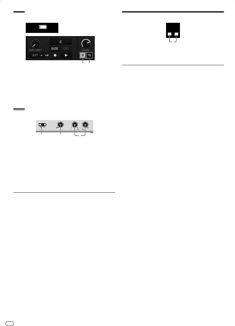
Global section
SNAP  1
1
QUANTIZE
1 (SHIFT)+1
1SNAP (QUANTIZE) button
!Press:
Turns the TRAKTOR snap function on and off.
When the snap function is on, the cue and loop points are set to the same position as the nearest [Beat Grid].
![SHIFT] + press:
Turns the TRAKTOR quantize function on and off.
When the quantize function is on, movement to the cue and loop points is synchronized with the timing of the beats.
MIC/AUX section
MIC |
OFF AUX |
0 |
12 |
12 |
12 |
12 |
INPUT SELECT |
LEVEL |
LOW |
|
EQ |
HI |
|
1 |
2 |
3 |
1 INPUT SELECT switch
Switches the audio input between the external device and the microphone.
—[AUX]: The external device connected to the [AUX] terminals is selected.
—[OFF]: The [MIC/AUX] channel is turned off.
—[MIC]: The microphone connected to the [MIC] terminal is selected.
!The sound input to the [MIC] and [AUX] terminals is mixed with the [CH 1] and [CH 2] sound that has passed through the crossfader.
2 LEVEL control
Adjusts the audio level input to the [MIC] and [AUX] terminals.
3 EQ (HI, LOW) controls
These adjust the tone of the [MIC/AUX] channel.
Inputting the sound of a microphone or external device
1Connect the external device to the [MIC] or [AUX] terminal.
2Switch the [INPUT SELECT] switch.
3Turn the [LEVEL] control.
Adjust the audio level input to the [MIC] or [AUX] terminal.
!Pay attention that rotating to the extreme right position outputs a very loud sound.
Adjusting the sound quality
Turn the [EQ (HI, LOW)] controls.
Refer to Specifications on page 30 for the range of sound that can be adjusted by each control.
MIDI section
MIDI
ON/OFF
CH1 CH2
1
This unit outputs the operation information of buttons and controls in universal MIDI format.
When connected by USB cable to a computer on which a MIDI-compatible DJ software program is installed, the DJ software can be operated from this unit.
Operating DJ software using the MIDI function
Install the DJ software on your computer in advance. Also, adjust audio and MIDI settings for the DJ software.
!For MIDI channel setting instructions, see Setting the MIDI channel on page 24.
!For the messages output by this unit, see List of MIDI Messages on page 26.
1 Connect this unit’s [USB] terminal to the computer.
For instructions on connections, see Connecting the input/output terminals on page 10.
2Start the DJ software.
3Press the [CH 1] or [CH 2] button.
The mixer section’s MIDI function turns on.
Transmission of the mixer section’s MIDI messages begins.
!When a fader or control is moved, a message corresponding to the position is sent.
!When the [CH 1] or [CH 2] button is pressed again, transmission of the mixer section’s MIDI messages stops.
!The MIDI messages of the browse section, transport section, effect section and hot cue/sampler section are transmitted regardless of the [CH 1] and [CH 2] buttons.
22 En
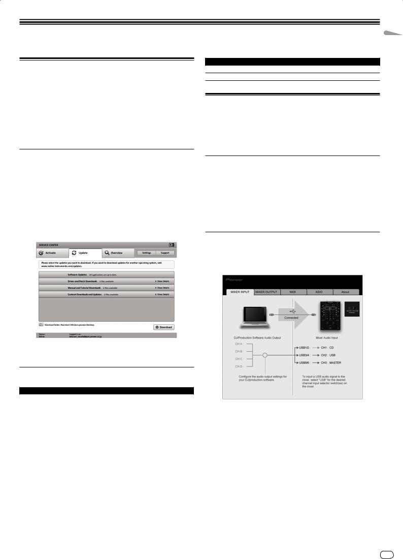
Changing the settings
Changing the TRAKTOR Preferences
Change TRAKTOR’s environmental settings according to the usage conditions of your hardware.
For details on TRAKTOR’s environmental settings, see the TRAKTOR manual.
!If you wish to restore the changes to the environmental settings to their defaults, please check the following website.
http://www.prodjnet.com/support/
1 Click the TRAKTOR [ (Preferences Button)] button.
Open the TRAKTOR settings menu.
2 Select the category and make the settings.
Category Descriptions
Controller Manager Assign TRAKTOR functions to this unit’s controls and buttons.
Traktor Kontrol X1 Set this when using Native Instruments’ Traktor Kontrol X1.
Changing the setting utility’s settings
The setting utility can be used to make the checks and settings described below.
—Checking the status of this unit’s [CD, PHONO, USB] input selector switch
—Setting the source of audio data output from this unit to the computer
—Adjusting the buffer size (when using Windows ASIO)
—Setting the MIDI channel
—Checking the version of the driver software
Updating the TRAKTOR software
When the computer is connected to the Internet, TRAKTOR software can be updated by accessing the Native Instruments SERVICE CENTER (referred to simply as “SERVICE CENTER” below).
1 Launch the SERVICE CENTER and log in.
For instructions on launching the SERVICE CENTER and logging in, see Launching the SERVICE CENTER on page 7.
2 Click the [Update] tab.
Available updates are checked.
3 Check the check box.
Specify the update to be downloaded.
4 Click [Download].
Updating begins.
List of TRAKTOR SCRATCH DUO 2 setting items
Category |
Descriptions |
|
Audio Setup |
Select the audio devices to be used for audio input/output. |
|
Set the audio latency when using a Macintosh computer. |
||
|
||
|
|
|
|
Select [Mixing Mode]. |
|
|
— [Internal]: Select this to control TRAKTOR mixer section from this |
|
Output Routing |
unit. |
|
— [External]: Select this to use this unit. |
||
|
||
|
Set the association between the TRAKTOR deck’s audio outputs and |
|
|
this unit’s input channels. |
|
Input Routing |
Set the association between the TRAKTOR deck’s audio inputs and this |
|
unit’s output channels. |
||
|
||
Timecode Setup |
Set this to use time codes (CONTROL CD/CONTROL VINYL). |
|
|
|
|
Loading |
Set the conditions and functions for loading tracks to the decks. |
|
Transport |
Make the settings related to the tempo and key lock functions. |
|
Decks |
Set the TRAKTOR deck section’s display method. |
|
|
|
|
Mixer |
Set auto gain to on or off. |
|
Set the TRAKTOR mixer section’s display method. |
||
|
||
|
|
|
Global Settings |
Set whether or not to display the global section. |
|
Effects |
Set the types of effects to be displayed when selecting effects. |
|
Mix Recorder |
Make the settings related to TRAKTOR recording functions. |
|
|
|
|
Browser Details |
Make the settings related to the [BROWSE] area and fonts. |
|
File Management |
Make the settings for track importing, auto analysis, the analysis BPM |
|
range, etc. |
||
|
Displaying the setting utility
!When using TRAKTOR, be sure to quit the settings utility.
For Windows
Click [Start] menu > [All Programs] > [Pioneer] > [DJM-T1] > [DJM-T1 Setting Utility].
For Mac OS X
Click [Macintosh HD] icon > [Application] > [Pioneer] > [DJM-T1] > [DJM-T1 Setting Utility].
Checking the status of this unit’s [CD, PHONO, USB] input selector switch
Display the setting utility before starting.
Click the [MIXER INPUT] tab.
English
En 23
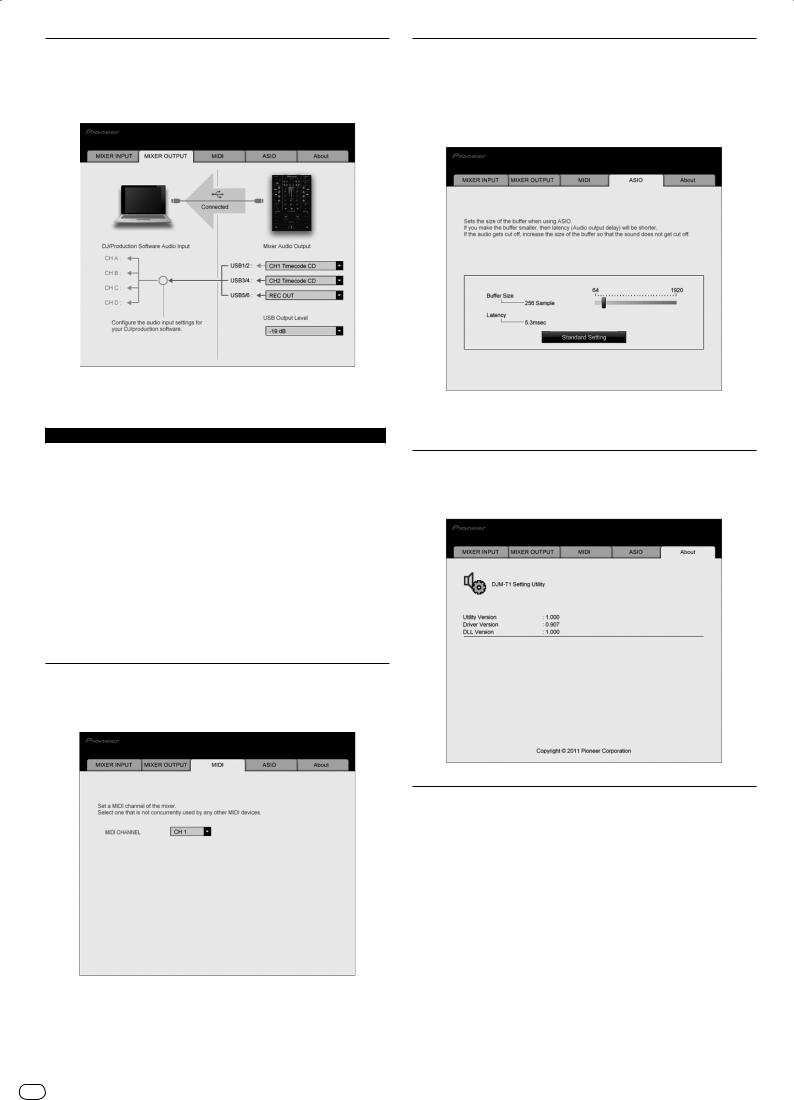
Setting the source of audio data output from this unit to the computer
Display the setting utility before starting.
1 Click the [MIXER OUTPUT] tab.
2 Click the [Mixer Audio Output] pull-down menu.
Select and set the audio data to be output to the computer from the flow of audio signals inside this unit.
USB 1/2 |
USB 3/4 |
USB 5/6 |
CH1 Timecode PHONO1 |
CH2 Timecode PHONO1 |
Post CH1 Fader |
CH1 Timecode CD1 |
CH2 Timecode CD1 |
Post CH2 Fader |
— |
— |
Cross Fader A |
— |
— |
Cross Fader B |
|
|
|
— |
— |
MIC/AUX Post EQ |
— |
— |
REC OUT |
1: The sound output from [USB 1/2] and [USB 3/4] is output with the same volume as input to this unit, regardless of the [USB Output Level] setting.
3 Click the [USB Output Level] pull-down menu.
Adjust the volume of the audio data output from [USB 5/6].
!If not enough volume can be achieved with the DJ software’s volume adjustment alone, change the [USB Output Level] setting to adjust the volume of the audio data output from this unit. Note that the sound will be distorted if the volume is raised too high.
Setting the MIDI channel
Display the setting utility before starting.
1 Click the [MIDI] tab.
2 Click the [MIDI CHANNEL] pull-down menu.
Select the desired MIDI channel.
Adjusting the buffer size (when using Windows ASIO)
If an application using this unit as the default audio device (DJ software, etc.) is running, quit that application before adjusting the buffer size.
Display the setting utility before starting.
Click the [ASIO] tab.
!If the buffer size is made large, drops in audio data (breaks in the sound) occur less easily, but the time lag due to the delay in the transfer of the audio data (latency) increases.
Checking the version of the driver software
Display the setting utility before starting.
Click the [About] tab.
Checking the latest information on the driver software
For the latest information on the driver software for exclusive use with this unit, visit our website shown below.
http://www.prodjnet.com/support/
!Operation cannot be guaranteed when multiple units of this mixer are connected to a single computer.
24 En

Changing this unit’s settings
1 Press the [UTILITY (WAKE UP)] button for over 1 second.
The [UTILITY (WAKE UP)] indicator and the top of the [CH 1] channel level indicator flash.
2 Press the [LOAD (DUPLICATE) B] button.
The setting item changes each time the [LOAD (DUPLICATE) B] button is pressed. The flashing position of the [CH 1] channel level indicator moves downwards.
!When the [LOAD (DUPLICATE) A] button is pressed, the selection returns to the previous setting item.
The flashing position of the [CH 1] channel level indicator moves upwards.
3 Turn the rotary selector.
Change the setting value.
!When the setting value can be switched on and off
—On: The green section of the [CH 2] channel level indicator lights.
—Off: The green section of the [CH 2] channel level indicator turns off.
!When the setting value can be switched in steps
—One’s place of setting value: Value indicated by the number of segments of the [CH 2] channel level indicator that are lit.
—Ten’s place of setting value: Value indicated by the number of segments of the master level indicator that are lit.
4 Press the rotary selector.
The settings are stored in this unit.
The [UTILITY (WAKE UP)] button flashes rapidly. Do not turn this unit’s power off while the settings are being stored.
!Storing is completed when the [UTILITY (WAKE UP)] button switches from flashing rapidly to flashing normally.
!Press the [UTILITY (WAKE UP)] button to return to normal operation.
About the auto standby function
When [Auto Standby] is set to [ON], the standby mode is set automatically if 4 hours pass with all of the conditions shown below met.
—That none of this unit’s buttons or controls are operated.
—That no audio signals are input to this unit’s input terminals.
—That no computer is connected by USB.
!When the [UTILITY (WAKE UP)] button is pressed, the standby mode is canceled.
!This unit is shipped with the auto standby function turned on. If you do not want to use the auto standby function, set [Auto Standby] to [OFF].
Setting preferences
Options settings |
Flashing position of [CH 1] |
Setting value |
Default value |
Descriptions |
|
|
|
|
channel level indicator |
|
|
|
|||||
|
|
|
|
|
|
|
||
Cross Fader Cut Lag |
Very top |
0 to 52 |
6 |
Adjusts the play at the edges of the crossfader (the cut lag). The cut lag can |
||||
be adjusted between 0.74 mm and 5.94 mm, in 0.1 mm units.1 |
||||||||
|
|
|
|
|||||
|
|
|
|
|
||||
Cross Fader Curve Slow A |
Second from top |
0 to 32 |
16 |
Adjusts the [CH 1] side attenuation curve characteristics when the [CROSS F. |
||||
CURVE (THRU, |
, |
)] switch is set to [ |
].2 |
|||||
|
|
|
|
|||||
|
|
|
|
|
||||
Cross Fader Curve Slow B |
Third from top |
0 to 32 |
16 |
Adjusts the [CH 2] side attenuation curve characteristics when the [CROSS F. |
||||
CURVE (THRU, |
, |
)] switch is set to [ |
].2 |
|||||
|
|
|
|
|||||
|
|
|
|
|
||||
Cross Fader Curve Fast A |
Fourth from top |
0 to 32 |
32 |
Adjusts the [CH 1] side attenuation curve characteristics when the [CROSS F. |
||||
CURVE (THRU, |
, |
)] switch is set to [ |
].2 |
|||||
|
|
|
|
|||||
|
|
|
|
|
||||
Cross Fader Curve Fast B |
Fifth from top |
0 to 32 |
32 |
Adjusts the [CH 2] side attenuation curve characteristics when the [CROSS F. |
||||
CURVE (THRU, |
, |
)] switch is set to [ |
].2 |
|||||
|
|
|
|
|||||
|
|
|
|
|
||||
|
|
|
|
Turns on and off the function for selecting effects using the effect control |
||||
Generic Controller Mode |
Sixth from top |
ON/OFF |
OFF |
buttons. |
|
|
|
|
When off, the LFO CONTROL and CROSS FADER CONTROL functions can |
||||||||
|
|
|
|
|||||
|
|
|
|
be used. |
|
|
|
|
Mic Output To Booth Monitor |
Seventh from top |
ON/OFF |
ON |
Sets whether or not to output the microphone’s audio signals from [BOOTH] |
||||
terminals. |
|
|
|
|||||
|
|
|
|
|
|
|
||
Auto Standby |
Eighth from top |
ON/OFF |
ON |
Turns the auto standby function on and off. |
|
|||
|
|
|
|
|
|
|
|
|
1If the setting value is extremely small, the sound may not be completely muted even when the crossfader is positioned at the very edge.
2Attenuation has an abrupt curve characteristic when the setting value is small, a gentle curve characteristic when the setting value is large.
English
En 25

List of MIDI Messages
List of MIDI Messages
Category |
SW Name |
SW Type |
MIDI message (this unit to computer) |
MIDI message (computer to this unit) |
Notes |
||||||||||||||
|
SHIFT OFF |
|
SHIFT ON |
|
SHIFT OFF |
|
SHIFT ON |
||||||||||||
|
|
|
|
|
|
|
|
||||||||||||
|
|
BTN |
9n |
|
00 |
dd |
9n |
|
40 |
dd |
— |
|
— |
— |
— |
|
— |
— |
OFF=0, ON=127 |
|
Rotary selector |
|
|
|
|
|
|
|
|
|
|
|
|
|
|
|
|
|
Turn clockwise: 0 – +30 |
|
VR |
Bn |
|
00 |
dd |
Bn |
|
40 |
dd |
— |
|
— |
— |
— |
|
— |
— |
/ Turn counterclockwise: |
|
|
|
|
|
|
|
||||||||||||||
|
|
|
|
|
|
|
|
|
|
|
|
|
|
|
|
|
|
|
-1 – -30 |
|
|
|
|
|
|
|
|
|
|
|
|
|
|
|
|
|
|
|
|
|
DECK A LOAD (DUPLICATE) |
BTN |
9n |
|
01 |
dd |
9n |
|
41 |
dd |
— |
|
— |
— |
— |
|
— |
— |
OFF=0, ON=127 |
|
button |
|
|
|
|
||||||||||||||
|
|
|
|
|
|
|
|
|
|
|
|
|
|
|
|
|
|
|
|
|
|
|
|
|
|
|
|
|
|
|
|
|
|
|
|
|
|
|
|
|
DECK B LOAD (DUPLICATE) |
BTN |
9n |
|
02 |
dd |
9n |
|
42 |
dd |
— |
|
— |
— |
— |
|
— |
— |
OFF=0, ON=127 |
|
button |
|
|
|
|
||||||||||||||
|
|
|
|
|
|
|
|
|
|
|
|
|
|
|
|
|
|
|
|
|
|
|
|
|
|
|
|
|
|
|
|
|
|
|
|
|
|
|
|
Transport sec- |
DECK A f (REL.) button |
BTN |
9n |
|
03 |
dd |
9n |
|
43 |
dd |
9n |
|
03 |
dd |
9n |
|
43 |
dd |
OFF=0, ON=127 |
|
|
|
|
|
|
|
|
|
|
|
|
|
|
|
|
|
|
|
|
DECK B f (REL.) button |
BTN |
9n |
|
04 |
dd |
9n |
|
44 |
dd |
9n |
|
04 |
dd |
9n |
|
44 |
dd |
OFF=0, ON=127 |
|
tion |
|
|
|
|
|||||||||||||||
DECK A SYNC (MASTER) button |
BTN |
9n |
|
05 |
dd |
9n |
|
45 |
dd |
9n |
|
05 |
dd |
9n |
|
45 |
dd |
OFF=0, ON=127 |
|
|
|
|
|
|
|||||||||||||||
|
DECK B SYNC (MASTER) button |
BTN |
9n |
|
06 |
dd |
9n |
|
46 |
dd |
9n |
|
06 |
dd |
9n |
|
46 |
dd |
OFF=0, ON=127 |
|
|
|
|
|
|
|
|
|
|
|
|
|
|
|
|
|
|
|
|
|
DECK A FX ASSIGN FX1 button |
BTN |
9n |
|
07 |
dd |
9n |
|
47 |
dd |
9n |
|
07 |
dd |
9n |
|
47 |
dd |
OFF=0, ON=127 |
|
DECK B FX ASSIGN FX1 button |
BTN |
9n |
|
08 |
dd |
9n |
|
48 |
dd |
9n |
|
08 |
dd |
9n |
|
48 |
dd |
OFF=0, ON=127 |
|
DECK A FX ASSIGN FX2 button |
BTN |
9n |
|
09 |
dd |
9n |
|
49 |
dd |
9n |
|
09 |
dd |
9n |
|
49 |
dd |
OFF=0, ON=127 |
|
|
|
|
|
|
|
|
|
|
|
|
|
|
|
|
|
|
|
|
|
DECK B FX ASSIGN FX2 button |
BTN |
9n |
|
0A |
dd |
9n |
|
4A |
dd |
9n |
|
0A |
dd |
9n |
|
4A |
dd |
OFF=0, ON=127 |
|
DECK A CUE (ABS.) button |
BTN |
9n |
|
0B |
dd |
9n |
|
4B |
dd |
9n |
|
0B |
dd |
9n |
|
4B |
dd |
OFF=0, ON=127 |
|
|
|
|
|
|
|
|
|
|
|
|
|
|
|
|
|
|
|
|
|
DECK B CUE (ABS.) button |
BTN |
9n |
|
0C |
dd |
9n |
|
4C |
dd |
9n |
|
0C |
dd |
9n |
|
4C |
dd |
OFF=0, ON=127 |
|
FX1 DRY/WET control |
VR |
Bn |
|
01 |
dd |
Bn |
|
41 |
dd |
— |
|
— |
— |
— |
|
— |
— |
0-127 |
|
FX2 DRY/WET control |
VR |
Bn |
|
02 |
dd |
Bn |
|
42 |
dd |
— |
|
— |
— |
— |
|
— |
— |
0-127 |
|
|
|
|
|
|
|
|
|
|
|
|
|
|
|
|
|
|
|
|
|
FX1 ON (GROUP/SINGLE) button |
BTN |
9n |
|
0D |
dd |
9n |
|
4D |
dd |
9n |
|
0D |
dd |
9n |
|
4D |
dd |
OFF=0, ON=127 |
|
FX2 ON (GROUP/SINGLE) button |
BTN |
9n |
|
0E |
dd |
9n |
|
4E |
dd |
9n |
|
0E |
dd |
9n |
|
4E |
dd |
OFF=0, ON=127 |
|
FX1 EFFECT1 control |
VR |
Bn |
|
03 |
dd |
Bn |
|
43 |
dd |
— |
|
— |
— |
— |
|
— |
— |
0-127 |
|
|
|
|
|
|
|
|
|
|
|
|
|
|
|
|
|
|
|
|
|
FX2 EFFECT1 control |
VR |
Bn |
|
04 |
dd |
Bn |
|
44 |
dd |
— |
|
— |
— |
— |
|
— |
— |
0-127 |
|
FX1 EFFECT1 button |
BTN |
9n |
|
0F |
dd |
9n |
|
4F |
dd |
9n |
|
0F |
dd |
9n |
|
4F |
dd |
OFF=0, ON=127 |
|
|
|
|
|
|
|
|
|
|
|
|
|
|
|
|
|
|
|
|
Effect section |
FX2 EFFECT1 button |
BTN |
9n |
|
10 |
dd |
9n |
|
50 |
dd |
9n |
|
10 |
dd |
9n |
|
50 |
dd |
OFF=0, ON=127 |
|
|
|
|
|
|
|
|
|
|
|
|
|
|
|
|
|
|
|
|
FX1 EFFECT2 control |
VR |
Bn |
|
05 |
dd |
Bn |
|
45 |
dd |
— |
|
— |
— |
— |
|
— |
— |
0-127 |
|
|
|
|
|
|
|||||||||||||||
|
FX2 EFFECT2 control |
VR |
Bn |
|
06 |
dd |
Bn |
|
46 |
dd |
— |
|
— |
— |
— |
|
— |
— |
0-127 |
|
|
|
|
|
|
|
|
|
|
|
|
|
|
|
|
|
|
|
|
|
FX1 EFFECT2 button |
BTN |
9n |
|
11 |
dd |
9n |
|
51 |
dd |
9n |
|
11 |
dd |
9n |
|
51 |
dd |
OFF=0, ON=127 |
|
FX2 EFFECT2 button |
BTN |
9n |
|
12 |
dd |
9n |
|
52 |
dd |
9n |
|
12 |
dd |
9n |
|
52 |
dd |
OFF=0, ON=127 |
|
FX1 EFFECT3 control |
VR |
Bn |
|
07 |
dd |
Bn |
|
47 |
dd |
— |
|
— |
— |
— |
|
— |
— |
0-127 |
|
|
|
|
|
|
|
|
|
|
|
|
|
|
|
|
|
|
|
|
|
FX2 EFFECT3 control |
VR |
Bn |
|
08 |
dd |
Bn |
|
48 |
dd |
— |
|
— |
— |
— |
|
— |
— |
0-127 |
|
FX1 EFFECT3 button |
BTN |
9n |
|
13 |
dd |
9n |
|
53 |
dd |
9n |
|
13 |
dd |
9n |
|
53 |
dd |
OFF=0, ON=127 |
|
FX2 EFFECT3 button |
BTN |
9n |
|
14 |
dd |
9n |
|
54 |
dd |
9n |
|
14 |
dd |
9n |
|
54 |
dd |
OFF=0, ON=127 |
|
|
|
|
|
|
|
|
|
|
|
|
|
|
|
|
|
|
|
|
26 En

Category |
SW Name |
SW Type |
MIDI message (this unit to computer) |
MIDI message (computer to this unit) |
Notes |
||||||||||||||
|
SHIFT OFF |
|
SHIFT ON |
|
SHIFT OFF |
|
SHIFT ON |
||||||||||||
|
|
|
|
|
|
|
|
||||||||||||
|
|
BTN |
9n |
|
15 |
dd |
9n |
|
55 |
dd |
— |
|
— |
— |
— |
|
— |
— |
OFF=0, ON=1271 |
|
|
|
|
|
|
|
|
|
|
|
|
|
|
|
|
|
|
|
Turn clockwise: 0 – +30 |
|
DECK A AUTO LOOP (LOOP |
VR |
Bn |
|
09 |
dd |
Bn |
|
49 |
dd |
— |
|
— |
— |
— |
|
— |
— |
/ Turn counterclockwise: |
|
|
|
|
|
|
|
|
|
|
|
|
|
|
|
|
|
|
-1 – -301 |
|
|
MOVE/SAMPLE VOLUME) |
|
|
|
|
|
|
|
|
|
|
|
|
|
|
|
|
|
|
|
BTN |
9n |
|
16 |
dd |
9n |
|
56 |
dd |
— |
|
— |
— |
— |
|
— |
— |
OFF=0, ON=1272 |
|
|
control |
|
|
|
|
||||||||||||||
|
|
|
|
|
|
|
|
|
|
|
|
|
|
|
|
|
|
|
Turn clockwise: 0 – +30 |
|
|
VR |
Bn |
|
0A |
dd |
Bn |
|
4A |
dd |
— |
|
— |
— |
— |
|
— |
— |
/ Turn counterclockwise: |
|
|
|
|
|
|
|
|
|
|
|
|
|
|
|
|
|
|
|
-1 – -302 |
|
|
BTN |
9n |
|
17 |
dd |
9n |
|
57 |
dd |
— |
|
— |
— |
— |
|
— |
— |
OFF=0, ON=1271 |
|
|
|
|
|
|
|
|
|
|
|
|
|
|
|
|
|
|
|
Turn clockwise: 0 – +30 |
|
DECK B AUTO LOOP (LOOP |
VR |
Bn |
|
0B |
dd |
Bn |
|
4B |
dd |
— |
|
— |
— |
— |
|
— |
— |
/ Turn counterclockwise: |
|
|
|
|
|
|
|
|
|
|
|
|
|
|
|
|
|
|
-1 – -301 |
|
|
MOVE/SAMPLE VOLUME) |
|
|
|
|
|
|
|
|
|
|
|
|
|
|
|
|
|
|
|
BTN |
9n |
|
18 |
dd |
9n |
|
58 |
dd |
— |
|
— |
— |
— |
|
— |
— |
OFF=0, ON=1272 |
|
|
control |
|
|
|
|
||||||||||||||
|
|
|
|
|
|
|
|
|
|
|
|
|
|
|
|
|
|
|
Turn clockwise: 0 – +30 |
|
|
VR |
Bn |
|
0C |
dd |
Bn |
|
4C |
dd |
— |
|
— |
— |
— |
|
— |
— |
/ Turn counterclockwise: |
|
|
|
|
|
|
|
|
|
|
|
|
|
|
|
|
|
|
|
-1 – -302 |
|
DECK A SELECT button |
BTN |
9n |
|
19 |
dd |
9n |
|
59 |
dd |
— |
|
— |
— |
— |
|
— |
— |
OFF=0, ON=127 |
|
|
|
|
|
|
|
|
|
|
|
|
|
|
|
|
|
|
|
|
|
DECK B SELECT button |
BTN |
9n |
|
1A |
dd |
9n |
|
5A |
dd |
— |
|
— |
— |
— |
|
— |
— |
OFF=0, ON=127 |
|
DECK A HOT CUE1 button |
BTN |
9n |
|
1B |
dd |
9n |
|
5B |
dd |
9n |
|
1B |
dd |
9n |
|
5B |
dd |
OFF=0, ON=1271 |
Hot cue/sampler |
BTN |
9n |
|
1C |
dd |
9n |
|
5C |
dd |
9n |
|
1C |
dd |
9n |
|
5C |
dd |
OFF=0, ON=1272 |
|
|
|
|
|
|
|||||||||||||||
section |
DECK B HOT CUE1 button |
BTN |
9n |
|
1D |
dd |
9n |
|
5D |
dd |
9n |
|
1D |
dd |
9n |
|
5D |
dd |
OFF=0, ON=1271 |
|
BTN |
9n |
|
1E |
dd |
9n |
|
5E |
dd |
9n |
|
1E |
dd |
9n |
|
5E |
dd |
OFF=0, ON=1272 |
|
|
|
|
|
|
|
||||||||||||||
|
DECK A HOT CUE2 button |
BTN |
9n |
|
1F |
dd |
9n |
|
5F |
dd |
9n |
|
1F |
dd |
9n |
|
5F |
dd |
OFF=0, ON=1271 |
|
BTN |
9n |
|
20 |
dd |
9n |
|
60 |
dd |
9n |
|
20 |
dd |
9n |
|
60 |
dd |
OFF=0, ON=1272 |
|
|
|
|
|
|
|
||||||||||||||
|
DECK B HOT CUE2 button |
BTN |
9n |
|
21 |
dd |
9n |
|
61 |
dd |
9n |
|
21 |
dd |
9n |
|
61 |
dd |
OFF=0, ON=1271 |
|
BTN |
9n |
|
22 |
dd |
9n |
|
62 |
dd |
9n |
|
22 |
dd |
9n |
|
62 |
dd |
OFF=0, ON=1272 |
|
|
|
|
|
|
|
||||||||||||||
|
DECK A HOT CUE3 button |
BTN |
9n |
|
23 |
dd |
9n |
|
63 |
dd |
9n |
|
23 |
dd |
9n |
|
63 |
dd |
OFF=0, ON=1271 |
|
BTN |
9n |
|
24 |
dd |
9n |
|
64 |
dd |
9n |
|
24 |
dd |
9n |
|
64 |
dd |
OFF=0, ON=1272 |
|
|
|
|
|
|
|
||||||||||||||
|
DECK B HOT CUE3 button |
BTN |
9n |
|
25 |
dd |
9n |
|
65 |
dd |
9n |
|
25 |
dd |
9n |
|
65 |
dd |
OFF=0, ON=1271 |
|
BTN |
9n |
|
26 |
dd |
9n |
|
66 |
dd |
9n |
|
26 |
dd |
9n |
|
66 |
dd |
OFF=0, ON=1272 |
|
|
|
|
|
|
|
||||||||||||||
|
DECK A HOT CUE4 button |
BTN |
9n |
|
27 |
dd |
9n |
|
67 |
dd |
9n |
|
27 |
dd |
9n |
|
67 |
dd |
OFF=0, ON=1271 |
|
BTN |
9n |
|
28 |
dd |
9n |
|
68 |
dd |
9n |
|
28 |
dd |
9n |
|
68 |
dd |
OFF=0, ON=1272 |
|
|
|
|
|
|
|
||||||||||||||
|
DECK B HOT CUE4 button |
BTN |
9n |
|
29 |
dd |
9n |
|
69 |
dd |
9n |
|
29 |
dd |
9n |
|
69 |
dd |
OFF=0, ON=1271 |
|
BTN |
9n |
|
2A |
dd |
9n |
|
6A |
dd |
9n |
|
2A |
dd |
9n |
|
6A |
dd |
OFF=0, ON=1272 |
|
|
|
|
|
|
|
||||||||||||||
|
DECK A ACTIVE button |
BTN |
9n |
|
2B |
dd |
9n |
|
6B |
dd |
9n |
|
2B |
dd |
9n |
|
6B |
dd |
OFF=0, ON=1271 |
|
BTN |
9n |
|
2C |
dd |
9n |
|
6C |
dd |
9n |
|
2C |
dd |
9n |
|
6C |
dd |
OFF=0, ON=1272 |
|
|
|
|
|
|
|
||||||||||||||
|
DECK B ACTIVE button |
BTN |
9n |
|
2D |
dd |
9n |
|
6D |
dd |
9n |
|
2D |
dd |
9n |
|
6D |
dd |
OFF=0, ON=1271 |
|
BTN |
9n |
|
2E |
dd |
9n |
|
6E |
dd |
9n |
|
2E |
dd |
9n |
|
6E |
dd |
OFF=0, ON=1272 |
|
|
|
|
|
|
|
||||||||||||||
|
CH 1 TRIM control |
VR |
Bn |
|
0D |
dd |
Bn |
|
4D |
dd |
— |
|
— |
— |
— |
|
— |
— |
0-127 |
|
CH 2 TRIM control |
VR |
Bn |
|
0E |
dd |
Bn |
|
4E |
dd |
— |
|
— |
— |
— |
|
— |
— |
0-127 |
|
CH 1 HI control |
VR |
Bn |
|
0F |
dd |
Bn |
|
4F |
dd |
— |
|
— |
— |
— |
|
— |
— |
0-127 |
|
|
|
|
|
|
|
|
|
|
|
|
|
|
|
|
|
|
|
|
|
CH 2 HI control |
VR |
Bn |
|
10 |
dd |
Bn |
|
50 |
dd |
— |
|
— |
— |
— |
|
— |
— |
0-127 |
|
CH 1 MID control |
VR |
Bn |
|
11 |
dd |
Bn |
|
51 |
dd |
— |
|
— |
— |
— |
|
— |
— |
0-127 |
|
CH 2 MID control |
VR |
Bn |
|
12 |
dd |
Bn |
|
52 |
dd |
— |
|
— |
— |
— |
|
— |
— |
0-127 |
|
|
|
|
|
|
|
|
|
|
|
|
|
|
|
|
|
|
|
|
Mixer section |
CH 1 LOW control |
VR |
Bn |
|
13 |
dd |
Bn |
|
53 |
dd |
— |
|
— |
— |
— |
|
— |
— |
0-127 |
CH 2 LOW control |
VR |
Bn |
|
14 |
dd |
Bn |
|
54 |
dd |
— |
|
— |
— |
— |
|
— |
— |
0-127 |
|
|
|
|
|
|
|||||||||||||||
|
|
|
|
|
|
|
|
|
|
|
|
|
|
|
|
|
|
|
|
|
CH 1 CUE (TAP) button |
BTN |
9n |
|
2F |
dd |
9n |
|
6F |
dd |
— |
|
— |
— |
9n |
|
6F |
dd |
OFF=0, ON=127 |
|
|
|
|
|
|
|
|
|
|
|
|
|
|
|
|
|
|
|
|
|
CH 2 CUE (TAP) button |
BTN |
9n |
|
30 |
dd |
9n |
|
70 |
dd |
— |
|
— |
— |
9n |
|
70 |
dd |
OFF=0, ON=127 |
|
CH 1 channel fader |
VR |
Bn |
|
15 |
dd |
Bn |
|
55 |
dd |
— |
|
— |
— |
— |
|
— |
— |
0-127 |
|
|
|
|
|
|
|
|
|
|
|
|
|
|
|
|
|
|
|
|
|
CH 2 channel fader |
VR |
Bn |
|
16 |
dd |
Bn |
|
56 |
dd |
— |
|
— |
— |
— |
|
— |
— |
0-127 |
|
CROSS FADER A |
VR |
Bn |
|
17 |
dd |
Bn |
|
57 |
dd |
— |
|
— |
— |
— |
|
— |
— |
0-127 |
|
CROSS FADER B |
VR |
Bn |
|
18 |
dd |
Bn |
|
58 |
dd |
— |
|
— |
— |
— |
|
— |
— |
0-127 |
|
|
|
|
|
|
|
|
|
|
|
|
|
|
|
|
|
|
|
|
Global section |
SNAP (QUANTIZE) button |
BTN |
9n |
|
31 |
dd |
9n |
|
71 |
dd |
9n |
|
31 |
dd |
9n |
|
71 |
dd |
OFF=0, ON=127 |
1When using with the hot cue function
2When using with the sampler function
English
En 27

Additional information
Troubleshooting
!Incorrect operation is often mistaken for trouble or malfunction. If you think that there is something wrong with this component, check the points below. Sometimes the trouble may lie in another component. Inspect the other components and electrical appliances being used. If the trouble cannot be rectified after checking the items below, ask your nearest Pioneer authorized service center or your dealer to carry out repair work.
!The player may not operate properly due to static electricity or other external influences. In such cases, normal operation may be restored by unplugging the power cord then plugging it back in.
Problem |
Check |
Remedy |
The power is not turned on. |
Is the power cord properly connected? |
Plug in the power cord to an AC outlet. |
|
|
|
This unit is not recognized. |
Is the [ON/OFF] switch for power supply set to [ON]? |
Set the [ON/OFF] switch for power supply to [ON]. |
|
|
|
|
Is the included USB cable properly connected? |
Connect the included USB cable properly. (page 10) |
|
Is [CTRL] lit in TRAKTOR? |
Press any button other than one in this unit’s mixer section and check that |
|
|
[CTRL] lights in TRAKTOR. |
|
— |
Check that [Pioneer. DJM-T1] is selected at [Preferences] > [Controller |
|
|
Manager] > [Device Setup] > [Device]. (page 23) |
Music files cannot be played. |
Are the music files damaged? |
Play music files that are not damaged. |
|
|
|
No tracks are displayed in the [TRACK] area. |
Have the music files been properly imported? |
Import the music files properly. (page 13) |
|
Have you selected a [Playlists] or [FAVORITES] slot that |
Select a [Playlists] or [FAVORITES] slot that contains tracks. |
|
does not contain any tracks? |
|
|
|
|
Volume of device connected to [AUX IN] terminals is |
Is the [LEVEL] control on the front panel set to the proper |
Adjust the [LEVEL] control on the front panel according to the connected |
low. |
position? |
device. (page 22) |
|
|
|
Distorted sound. |
Are the [MAIN VOL] and [GAIN] controls of TRAKTOR set to |
Adjust the [MAIN VOL] and [GAIN] controls while watching the [MAIN] level |
|
the proper positions? |
indicator in TRAKTOR. |
|
Is the audio level being input to the [AUX IN] and [MIC] |
Set the audio level input to the terminals to a suitable level for the connected |
|
terminals set to a suitable level? |
devices. |
|
Is the sound level output from the [MASTER] channel |
Adjust the [MASTER LEVEL] control so that the master channel level indicator |
|
appropriately set? |
lights at around [0 dB] at the peak level. (page 16) |
|
|
If the sound is distorted even when the [MASTER LEVEL] control is adjusted, |
|
|
set [MASTER ATT.] to [–6 dB]. (page 10) |
Is the level of audio input to each channel properly set?
Adjust the [TRIM] control so that the channel level indicator lights at about [0 dB] at the peak level. (page 16)
Sound being played is interrupted.
Are the included power cord and the included USB cable properly connected?
The sound will be interrupted if the included power cord or the included USB cable is disconnected from the main unit during playback.
Properly fasten the included USB cable to the cord hook on the main unit. (page 10)
Is the audio latency value suitable?
When using Windows, open the [ASIO] tab in the settings utility and set the audio latency to a suitable value.
When using a Macintosh computer, set [Preferences] > [Audio Setup] > [Latency] in TRAKTOR to a suitable value. (page 24)
Sound of an external device or microphone cannot be |
Is the [INPUT SELECT] switch on the front panel set to the |
Set the [INPUT SELECT] switch to the [AUX] position when using an external |
output. |
[OFF] position? |
device, to the [MIC] position when using a microphone. (page 22) |
|
|
|
No sound is produced. |
Are the connection cables properly connected? |
Connect the connection cables properly. (page 10) |
|
|
|
|
Is the included USB cable properly connected? |
Connect the computer and this unit directly using the included USB cable. |
|
|
USB hubs cannot be used. (page 10) |
|
|
|
|
Are terminals or plugs dirty? |
Wipe any dirt off terminals and plugs before connecting. |
|
Is the driver software properly installed on your computer? |
Install the driver software properly on the computer. (page 8) |
|
|
|
|
Are [Audio Setup], [Output Routing] and [Input Routing] |
Check that [Preferences] is set as shown below. (Page 23) |
|
in TRAKTOR properly set? |
[Audio Setup] > [Audio Device] > [PIONEER DJM-T1 (Core Audio)] (Mac |
|
|
OS X) or [PIONEER DJM-T1 ASIO (ASIO)] (Windows) |
|
|
[Output Routing] > [Output Deck A] [L] > [1.PIONEER DJM-T1 OUT 1] and |
|
|
[R] > [2.PIONEER DJM-T1 OUT 2] |
|
|
[Output Routing] > [Output Deck B] [L] > [3.PIONEER DJM-T1 OUT 3] and |
|
|
[R] > [4.PIONEER DJM-T1 OUT 4] |
|
|
[Input Routing] > [Input Deck A] [L(Mono)] > [1.PIONEER DJM-T1 IN 1] |
|
|
and [R] > [2.PIONEER DJM-T1 IN 2] |
|
|
[Input Routing] > [Input Deck B] [L(Mono)] > [3.PIONEER DJM-T1 IN 3] and |
|
|
[R] > [4.PIONEER DJM-T1 IN 4] |
|
|
|
|
Are the connected components and amplifiers properly set? |
Set the external input selection and volume on the components and amplifiers |
|
|
properly. |
|
|
|
No sound or small sound. |
Is the [CD, PHONO, USB] input selector switch set to the |
Switch the [CD, PHONO, USB] input selector switch and switch the channel’s |
|
proper position? |
input source. (page 16) |
|
|
|
|
Is [MASTER ATT.] set to [–6 dB]? |
Set [MASTER ATT.] to [0 dB]. (page 10) |
BPM or overall waveform is not displayed. |
Has the music file been analyzed? |
Put a check at [Preferences] > [File Management] > [Analyze new tracks |
|
|
when loading into deck], then reload the track in the deck. |
[SYNC] function does not work.
Have the music files been properly imported? |
Reimport the music files and load them in the decks. (page 13) |
Has the music file been analyzed? |
If music files cannot be analyzed automatically, input the [Beat Grid] manu- |
|
ally. |
[SYNC] function does not work even when files are analyzed.
Is [BEAT MARKER (Grid)] set for hot cue?
Set at least one [BEAT MARKER] to [Grid].
Put a check at [Preferences] > [File Management] > [Set Beat-Grid when detecting BPM], then reload the track in the deck.
|
On the TRAKTOR operation screen, is the [BPM] of the track |
The [SYNC] function will not operate normally if the [BPM] of the track for |
|
for which the [MASTER] icon is lit too different from the |
which the [MASTER] icon is lit is out of the adjustable tempo range for the |
|
[BPM] of the track for which the [SYNC] icon is lit? |
track for which the [SYNC] icon is lit. |
|
Are you scratching? |
The [SYNC] function is disabled when scratching. |
|
|
|
Deck area display is small. |
— |
Double-click the track information display section (the part where the track |
|
|
name, BPM, etc., are displayed) in the deck area. |
|
|
|
28 En
 Loading...