


DJM-700S
DJ MIXER
TABLE DE MIXAGE
DJ-MISCHPULT
MIXER PER DJ
DJ MENGPANEEL
MESA DE MEZCLAS DJ
DJM-700-S
DJM-700-K
Operating Instructions
Mode d’emploi
Bedienungsanleitung
Istruzioni per l’uso
Gebruiksaanwijzing
Manual de instrucciones
Инструкции по эксплуатации
01_DJM-700_En.book 1 ページ 2007年7月10日 火曜日 午後8時41分
This product complies with the Low Voltage Directive
2006/95/EC and EMC Directive 2004/108/EC.
D3-4-2-1-9a_A_En
The exclamation point within an equilateral
triangle is intended to alert the user to the
presence of important operating and
maintenance (servicing) instructions in the
literature accompanying the appliance.
The lightning flash with arrowhead symbol,
within an equilateral triangle, is intended to
alert the user to the presence of uninsulated
"dangerous voltage" within the product's
enclosure that may be of sufficient
magnitude to constitute a risk of electric
shock to persons.
CAUTION:
TO PREVENT THE RISK OF ELECTRIC
SHOCK, DO NOT REMOVE COVER (OR
BACK). NO USER-SERVICEABLE PARTS
INSIDE. REFER SERVICING TO QUALIFIED
SERVICE PERSONNEL.
CAUTION
RISK OF ELECTRIC SHOCK
DO NOT OPEN
IMPORTANT
D3-4-2-1-1_En-A
Replacement and mounting of an AC plug on the power supply cord of this unit should be performed only by qualified
service personnel.
D3-4-2-1-2-2_B_En
IMPORTANT: THE MOULDED PLUG
This appliance is supplied with a moulded three pin mains plug for your safety and convenience. A 5 amp fuse is fitted in this plug. Should the
fuse need to be replaced, please ensure that the replacement fuse has a rating of 5 amps and that it is approved by ASTA or BSI to BS1362.
Check for the ASTA mark or the BSI mark on the body of the fuse.
If the plug contains a removable fuse cover, you must ensure that it is refitted when the fuse is replaced. If you lose the fuse cover the plug
must not be used until a replacement cover is obtained. A replacement fuse cover can be obtained from your local dealer.
If the fitted moulded plug is unsuitable for your socket outlet, then the fuse shall be removed and the plug cut off and disposed of
safely. There is a danger of severe electrical shock if the cut off plug is inserted into any 13 amp socket.
If a new plug is to be fitted, please observe the wiring code as shown below. If in any doubt, please consult a qualified electrician.
IMPORTANT: The wires in this mains lead are coloured in accordance with the following code:
Blue : Neutral Brown : Live
As the colours of the wires in the mains lead of this appliance may not correspond with the coloured markings identifying the terminals in
your plug, proceed as follows ;
The wire which is coloured BLUE must be connected to the terminal which is marked with the
letter N or coloured BLACK.
The wire which is coloured BROWN must be connected to the terminal which is marked with the
letter L or coloured RED.
How to replace the fuse: Open the fuse compartment with a screwdriver and replace the fuse.
Operating Environment
Operating environment temperature and humidity:
+5 ºC – +35 ºC (+41 ºF – +95 ºF); less than 85 %RH
(cooling vents not blocked)
Do not install this unit in a poorly ventilated area, or in
locations exposed to high humidity or direct sunlight (or
strong artificial light)
D3-4-2-1-7c_A_En
WARNING
To prevent a fire hazard, do not place any naked
flame sources (such as a lighted candle) on the
equipment.
D3-4-2-1-7a_A_En
If you want to dispose this product, do not mix it with general household waste. There is a separate collection system for used
electronic products in accordance with legislation that requires proper treatment, recovery and recycling.
Private households in the member states of the EU, in Switzerland and Norway may return their used electronic products free of charge to
designated collection facilities or to a retailer (if you purchase a similar new one).
For countries not mentioned above, please contact your local authorities for the correct method of disposal.
By doing so you will ensure that your disposed product undergoes the necessary treatment, recovery and recycling and thus prevent potential
negative effects on the environment and human health.
K058_A_En
If the AC plug of this unit does not match the AC
outlet you want to use, the plug must be removed
and appropriate one fitted. Replacement and
mounting of an AC plug on the power supply cord of
this unit should be performed only by qualified
service personnel. If connected to an AC outlet, the
cut-off plug can cause severe electrical shock. Make
sure it is properly disposed of after removal.
The equipment should be disconnected by removing
the mains plug from the wall socket when left
unused for a long period of time (for example, when
on vacation).
D3-4-2-2-1a_A_En
CAUTION
The POWER switch on this unit will not completely
shut off all power from the AC outlet. Since the
power cord serves as the main disconnect device for
the unit, you will need to unplug it from the AC outlet
to shut down all power. Therefore, make sure the
unit has been installed so that the power cord can
be easily unplugged from the AC outlet in case of an
accident. To avoid fire hazard, the power cord should
also be unplugged from the AC outlet when left
unused for a long period of time (for example, when
on vacation).
D3-4-2-2-2a_A_En
WARNING
This equipment is not waterproof. To prevent a fire
or shock hazard, do not place any container filed
with liquid near this equipment (such as a vase or
flower pot) or expose it to dripping, splashing, rain
or moisture. D3-4-2-1-3_A_En
VENTILATION CAUTION
When installing this unit, make sure to leave space
around the unit for ventilation to improve heat
radiation (at least 5 cm atrear,and3cmateach
side).
WARNING
Slots and openings in the cabinet are provided for
ventilation to ensure reliable operation of the
product, and to protect it from overheating. To
prevent fire hazard, the openings should never be
blocked or covered with items (such as newspapers,
table-cloths, curtains) or by operating the
equipment on thick carpet or a bed.
D3-4-2-1-7b_A_En
POWER-CORD CAUTION
Handle the power cord by the plug. Do not pull out the
plug by tugging the cord and never touch the power
cord when your hands are wet as this could cause a
short circuit or electric shock. Do not place the unit, a
piece of furniture, etc., on the power cord, or pinch the
cord. Never make a knot in the cord or tie it with other
cords. The power cords should be routed such that they
are not likely to be stepped on. A damaged power cord
can cause a fire or give you an electrical shock. Check
the power cord once in a while. When you find it
damaged, ask your nearest PIONEER authorized
service center or your dealer for a replacement.
S002_En
Thank you for buying this Pioneer product.
Please read through these operating instructions so you will know how to operate your model properly. After you have finished
reading the instructions, put them away in a safe place for future reference.
In some countries or regions, the shape of the power plug and power outlet may sometimes differ from that shown in the
explanatory drawings. However the method of connecting and operating the unit is the same.
When using this product follow the instructions
written on the underside of the unit, which
concern rated voltage, etc.
D3-4-2-2-4_En
WARNING
The voltage of the available power supply differs
according to country or region. Be sure that the
power supply voltage of the area where this unit
will be used meets the required voltage (e.g., 230V
or 120V) written on the bottom panel.
D3-4-2-1-4_A_En
mod
Before plugging in for the first time, read the following
section carefully.
01_DJM-700_En.book 2 ページ 2007年7月10日 火曜日 午後8時41分

3
En
Contents
English
Contents
CONFIRM ACCESSORIES..............................................4
CAUTIONS REGARDING HANDLING............................4
Location.......................................................................................... 4
Cleaning the Unit........................................................................... 4
FEATURES ....................................................................4
CONNECTIONS .............................................................5
CONNECTION PANEL................................................................... 5
CONNECTING INPUTS.................................................................. 6
CONNECTING EXTERNAL EFFECTORS, OUTPUT
CONNECTORS ............................................................................... 7
ABOUT MIDI CONNECTORS........................................................ 8
CONNECTING MICROPHONE AND HEADPHONES ................. 8
CONNECTING THE POWER CORD.............................................. 8
NAMES AND FUNCTIONS OF PARTS ...........................9
MIXER OPERATIONS..................................................13
FADER START FUNCTION .......................................................... 14
EFFECT FUNCTIONS ...................................................16
PRODUCING BEAT EFFECTS ..................................................... 18
MANUAL FILTER OPERATION ................................................... 19
EFFECT FREQUENCY FILTER OPERATION ............................... 19
EFFECT PARAMETERS................................................................ 20
MIDI SETTINGS ..........................................................21
SYNCHRONIZING AUDIO SIGNALS TO EXTERNAL
SEQUENCER, OR USING DJM-700-S/DJM-700-K
INFORMATION TO OPERATE AN EXTERNAL
SEQUENCER................................................................................ 21
MIDI MESSAGES ......................................................................... 22
PROGRAM CHANGE................................................................... 24
SNAPSHOT .................................................................................. 24
MIDI ON/OFF................................................................................ 24
TROUBLESHOOTING...................................................25
SPECIFICATIONS ........................................................26
01_DJM-700_En.book 3 ページ 2007年7月10日 火曜日 午後8時41分

4
En
CONFIRM
ACCESSORIES
Operating Instructions. . . . . . . . . . . . . . . . . . . . . . . . . . . . . . . . . . . . .1
CAUTIONS REGARDING
HANDLING
Location
Install the unit in a well-ventilated location where it will
not be exposed to high temperatures or humidity.
• Do not install the unit in a location which is exposed to direct
rays of the sun, or near stoves or radiators. Excessive heat
can adversely affect the cabinet and internal components.
Installation of the unit in a damp or dusty environment may
also result in a malfunction or accident. (Avoid installation
near cookers etc., where the unit may be exposed to oily
smoke, steam or heat.)
• When the unit is used inside a carrying case or DJ booth,
separate it from the walls or other equipment to improve
heat radiation.
Cleaning the Unit
• Use a polishing cloth to wipe off dust and dirt.
• When the surfaces are very dirty, wipe with a soft cloth
dipped in some neutral cleanser diluted five or six times with
water and wrung out well, then wipe again with a dry cloth.
Do not use furniture wax or cleaners.
• Never use thinners, benzene, insecticide sprays or other
chemicals on or near this unit, since these will corrode the
surfaces.
FEATURES
Designed for high sound quality
Analog signals are transmitted by the shortest circuitry and
converted to digital format at 96 kHz sampling rate via a 24-bit high
quality A/D converter. As a result, signals are passed to the digital
mixing stage in the best possible state. Mixing is performed with a
32-bit DSP, totally eliminating any loss in fidelity, while the ideal
level of filtering is introduced to produce optimum sound for DJ
play.
These features are housed in a high-rigidity chassis with high-
output power section and other features that carry on the high-
fidelity performance of the DJM-1000, thus ensuring the utmost in
clear and powerful club sound.
Manual Filter
This unit features Manual Effecter for more intuitive setting of
effects, thus expanding the potential range of DJ play. In addition,
by combining this with “beat effects,” an even wider range of
effects can be produced, allowing a tremendous variety of remix
and DJ play.
Beat effects
The “beat effects” so popular on the DJM-600 are continued here.
Effects can be applied in linkage to the BPM (Beats Per Minute)
count, thus allowing the production of a variety of sounds.
Equipped with a broad range of special effects, including delay,
echo, trans, filter, flanger, phaser, reverb, robot, crush, roll, reverse
roll, uproll, and downroll.
This unit features an “effect frequency filter” allowing the user to
limit what frequency bands are subjected to effects, and which are
not. This enhances the degree of audio expression compared to
conventional effecters that are applied to the entire frequency
range.
Digital OUT
The digital output connectors support sampling rates 96 kHz/24-
bit format and 48 kHz/24-bit format, making the unit even more
convenient for cutting studio tracks or on other occasions when
high sound fidelity is required. (Only linear PCM is supported.)
MIDI OUT
Virtually all the dial and switch information of the DJM-700-S/
DJM-700-K can be output in MIDI signal format, allowing a
component supporting MIDI control to be controlled via MIDI.
Other functions
•A control cable can be used to connect the unit to a Pioneer DJ
CD player, thus allowing playback to be linked to operation of the
fader (“fader start play”).
• Built-in “3-band equalizer” supports level control within the
range of +6 dB to –26 dB in each bandwidth.
• “Cross fader assignment” function allows each channel’s input
to be assigned flexibly to a cross fader.
• “Talk over” function automatically lowers track volume during
microphone input.
• “Fader curve adjustment” function allows modification of the
cross fader and channel fader curves.
01_DJM-700_En.book 4 ページ 2007年7月10日 火曜日 午後8時41分
CONNECTIONS
5
En
English
CONNECTIONS
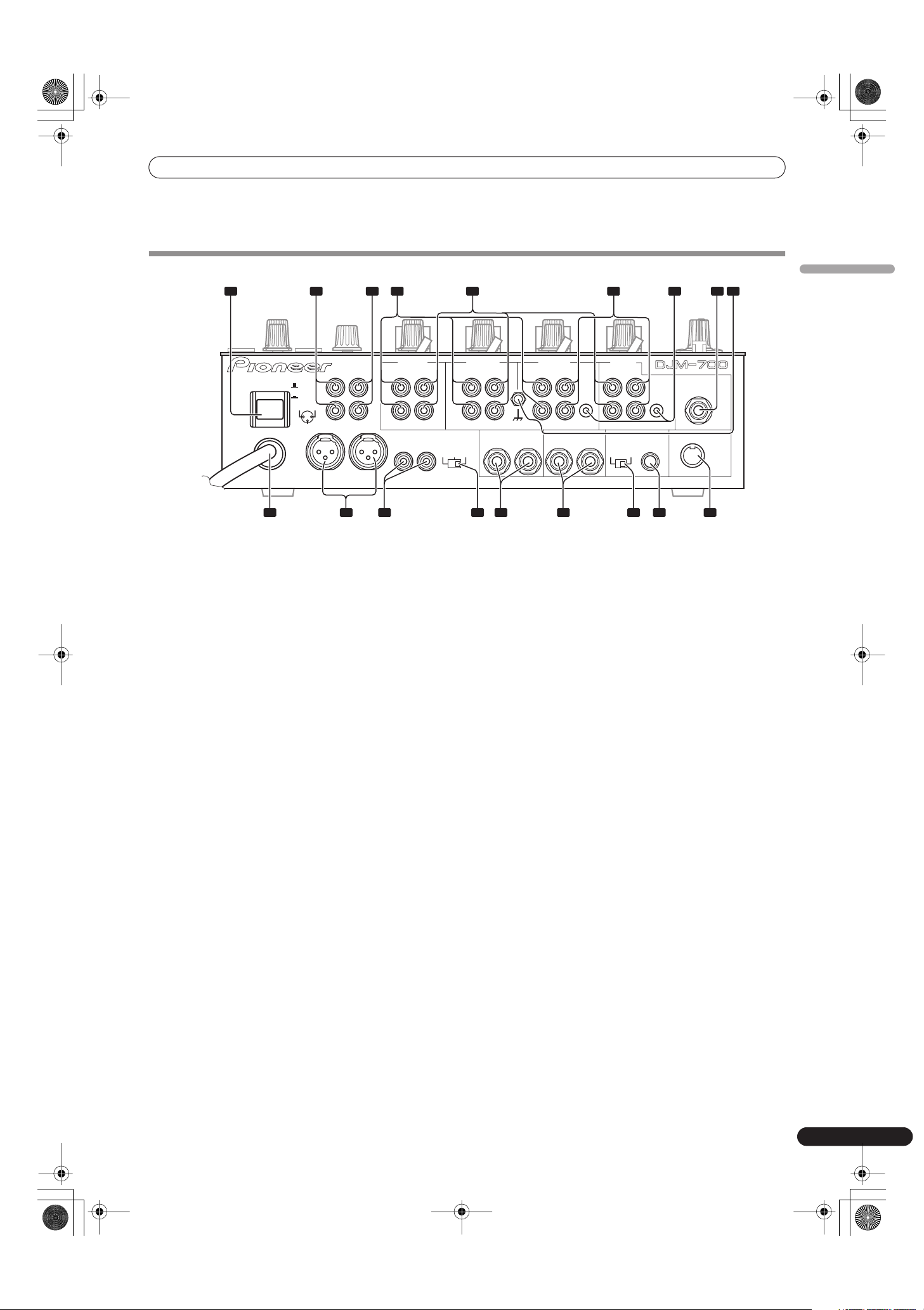
CONNECTION PANEL
1 POWER switch
2 BOOTH monitor output connectors
RCA-type booth monitor output jack.
The sound level from these connectors is controlled independently
by the
BOOTH MONITOR LEVEL
dial, regardless of the position of
the
MASTER LEVEL
dial.
3 Recording output connectors (REC)
RCA type output connectors for recording.
4 PHONO input connectors
RCA type phono level (MM cartridge) input connectors.
Do not use for inputting line level signals.
5 LINE input connectors
RCA type line level input connectors.
Use to connect a cassette deck or other line level output
component.
6CD input connectors
RCA type line level input connectors.
Use to connect a DJ CD player or other line level output
component.
7 CONTROL connectors
Ø3.5 mm mini-connector. Use to connect to the control connector
of a Pioneer DJ CD player.
When the connectors are connected, the DJM-700-S/DJM-700-K’s
fader can be used to perform start/stop on the DJ CD player.
8 Two microphone input jacks (MIC 2)
Connect microphones equipped with phone-type plugs.
9 Signal grounding terminals (SIGNAL GND)
Reduces noise when connecting an analog turntable.
10 MIDI OUT connector
DIN type output connector.
Use to connect to other MIDI component (see P. 21).
11 DIGITAL OUT connector
RCA type digital coaxial output connector.
Master audio digital output.
12 Sampling frequency selector switch (fs 48 k/96 k)
Use to set the sampling frequency of the digital output to 96 kHz/
24-bit format or 48 kHz/24-bit format.
• Turn power off before changing this switch position.
13 RETURN connectors
Ø6.3 mm phone-type input connectors.
Use to connect to the output connectors of external effectors or
similar components.
When the L channel only is connected, the L channel input is
simultaneously input to the R channel.
14 SEND output connectors
Ø6.3 mm phone-type output connectors.
Use to connect to the input connectors of external effectors or
other similar components. When the L channel only is connected,
a L+R monaural signal is output.
15 Master output attenuator switch (MASTER ATT)
Use to attenuate the level of the master 1 and master 2 outputs.
Attenuation can be set to 0 dB, –3 dB, or –6 dB.
16 MASTER 2 output connectors
RCA type unbalanced output.
17 MASTER 1 output connectors
XLR type (male) balanced output.
• When using a cord with RCA-type plug, users are recommended
to connect the plug directly to the
MASTER 2
connectors
without using an XLR/RCA converter plug.
18 Power cord
Connect to ordinary AC outlet.
POWER
ON
OFF
BOOTH REC
L
R
L
R
L
R
L
R
L
R
PHONO LINE
CH-4 CH-3 CH-2 CH-1
PHONO LINE PHONO
SIGNAL GND
SEND
DIGITAL OUT
(MONO)
CD
RL
LINE
CONTROL
CONTROL
CD
1 GND
3 COLD
2 HOT
-6dB -3dB 0dB
MIC 2
RETURN
(MONO)
RL
RL
RL
MASTER1
MASTER2
MASTER
ATT.
48k 96k
fs(Hz)
MIDI OUT
1 2 3 4 7 8 9
101112151718 1316 14
5 6
01_DJM-700_En.book 5 ページ 2007年7月10日 火曜日 午後8時41分
CONNECTIONS
6
En
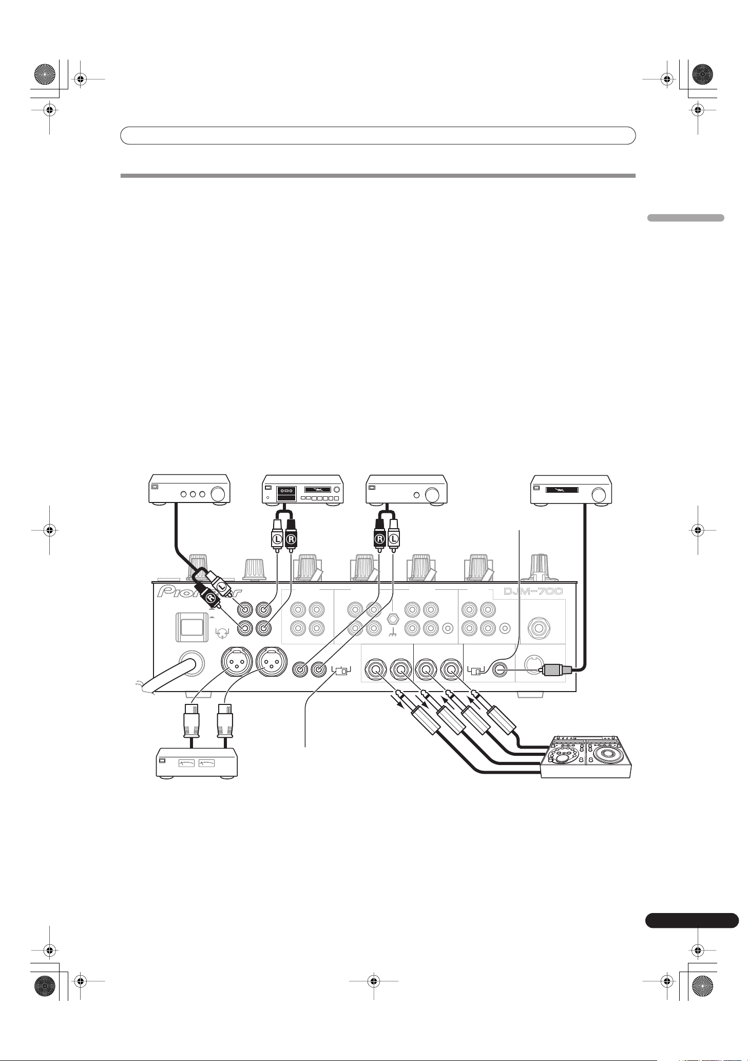
Always turn off the power switch and disconnect the power plug from its outlet when making or changing connections.
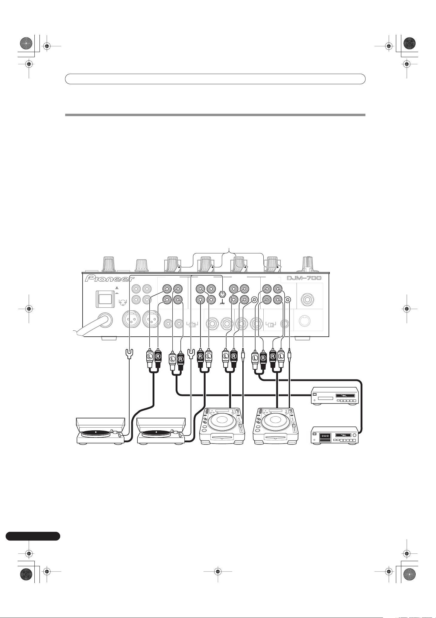
CONNECTING INPUTS
Pioneer DJ CD players
The audio output connectors of a DJ-type CD player can be
connected to the
CD
input connectors (channel 1 or 2), or to the
LINE
input connectors (channel 1) of the DJM-700-S/DJM-700-K.
Connect the control cord to the
CONTROL
jack, and set the input
selector switch to [
CD
] or [
LINE
].
Analog turntable
To connect an analog turntable, connect the turntable’s audio
output cable to one of the channel 2 to 4
PHONO
input
connectors. Set the corresponding channel’s input selector switch
to [
PHONO
]. The DJM-700-S/DJM-700-K’s
PHONO
inputs support
MM cartridges.
Connect the ground wire from an analog turntable to the
SIGNAL GND
terminal of the DJM-700-S/DJM-700-K.
• Note that no
PHONO
input connector is provided for channel 1.
Connecting other line level output devices
To use a cassette deck or ordinary CD player, connect its audio
output connectors to one of the DJM-700-S/DJM-700-K’s
LINE
input connectors (channel 1, 3, or 4) or to the
CD
input connectors
(channel 1 or 2), and set the input selector switch to [
LINE
].
POWER
ON
OFF
BOOTH REC
L
R
L
R
L
R
L
R
L
R
PHONO LINE
CH-4 CH-3 CH-2 CH-1
PHONO LINE PHONO
SIGNAL GND
SEND
DIGITAL OUT
(MONO)
CD
RL
LINE
CONTROL
CONTROL
CD
1 GND
3 COLD
2 HOT
-6dB -3dB 0dB
MIC 2
RETURN
(MONO)
RL
RL
RL
MASTER1
MASTER2
MASTER
ATT.
48k 96k
fs(Hz)
MIDI OUT
Input selector switch
Analog turntable Analog turntable DJ CD player DJ CD player Cassette deck, etc.
CD player, etc.
01_DJM-700_En.book 6 ページ 2007年7月10日 火曜日 午後8時41分
CONNECTIONS
7
En
English
CONNECTING EXTERNAL EFFECTORS, OUTPUT CONNECTORS
Master output
This unit is furnished with balanced output
MASTER 1
(supporting
XLR plugs), and unbalanced output
MASTER 2
(supporting RCA
plugs).
Using the
MASTER ATT
switch, adjust the output level to match
the input sensitivity of the power amplifier used.
If the operating panel’s
MONO/STEREO
switch is set to [
MONO
],
the master output will be a monaural combination of L+R
channels.
Booth monitor output
Unbalanced output supporting RCA-type plug. The sound volume
for this output is controlled by the
BOOTH MONITOR LEVEL
dial,
independently of the master output level setting.
Recording output
These are output connectors for recording, supporting RCA plugs.
Digital output
This is a coaxial digital output connector, supporting RCA plugs.
The sampling frequency can be set to 96 kHz/24-bit format or
48 kHz/24-bit format to match the connected device.
• Turn power off before changing this switch position.
External effector
Use a cable with Ø6.3 mm phone plugs to connect the DJ mixer’s
SEND
connectors to the effector’s input connectors.
When using an effector with monaural inputs, connect only to the
DJ mixer’s L channel output. In this way, the mixed L+R audio
signal will be sent to the effector. In the same way, use a cable with
Ø6.3 mm phone plugs to connect the DJ mixer’s
RETURN
connectors to the output connectors of the effector.
If the effector has only monaural output, connect to the DJ mixer’s
L channel input only. The signal from the effector will be input to
both L and R channels.
When using an external effector, set the effect selector to [
SND/
RTN
].
POWER
ON
OFF
BOOTH REC
L
R
L
R
L
R
L
R
L
R
PHONO LINE
CH-4 CH-3 CH-2 CH-1
PHONO LINE PHONO
SIGNAL GND
SEND
DIGITAL OUT
(MONO)
CD
RL
LINE
CONTROL
CONTROL
CD
1 GND
3 COLD
2 HOT
-6dB -3dB 0dB
MIC 2
RETURN
(MONO)
RL
RL
RL
MASTER1
MASTER2
MASTER
ATT.
48k 96k
fs(Hz)
MIDI OUT
Power amplifier
(RCA plug input
connectors)
Cassette deck
(analog input
recording device)
Sampling frequency
selector switch
Digital input AV amplifier
(digital input
recording device)
Power amplifier
(XLR plug input connectors)
MASTER ATT switch
Power amplifier
(for booth monitor)
External effector
01_DJM-700_En.book 7 ページ 2007年7月10日 火曜日 午後8時41分
CONNECTIONS
8
En
ABOUT MIDI CONNECTORS
See P. 21 regarding the functions of MIDI connectors.
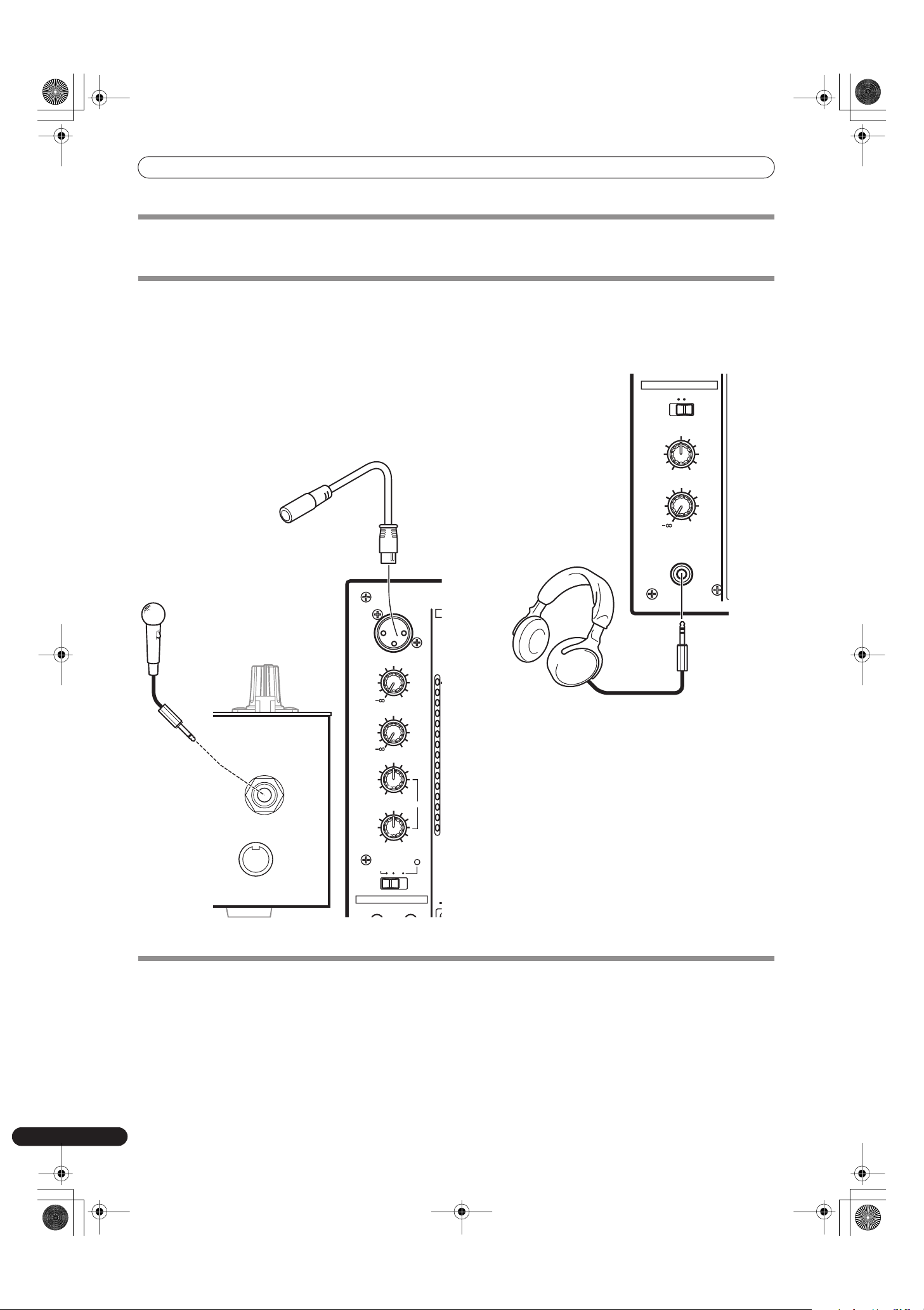
CONNECTING MICROPHONE AND HEADPHONES
Microphone
A microphone with XLR-type plug can be connected to the
MIC 1
connector on the Operation Panel (upper) .
The
MIC 2
jack on the connection panel can be used to connect a
microphone with Ø6.3 mm phone plugs.
• When using a microphone, set the operating panel’s
MIC
switch
to [
ON
] or [
TALK OVER
], and adjust the
LEVEL
dial as
necessary.
When not using a microphone, it is recommended to set the
MIC
switch to [
OFF
] and rotate the
LEVEL
dial fully
counterclockwise to the [–
∞
] side.
Headphones
The
PHONES
jack on the upper surface of the operating panel can
be used to connect headphones with a Ø6.3 mm stereo phone
plug.
CONNECTING THE POWER CORD
Connect the power cord last.
• After completing all other connections, connect the power plug to an ordinary AC outlet.
MIC 2
MIDI OUT
d
OV
1
7
4
2
1
0
–
–
–
–
–
–
–
–
FADER START
MIC1
MIC1 LEVEL
0
MIC2 LEVEL
0
HI
MIC
CH-1 CH-2
OFF ON
TAL K
OVER
+12-12
LOW
+12-12
EQ
Microphone 1
Microphone 2
HEADPHONES
LEVEL
0
MIXING
MASTERCUE
MONO SPLIT STEREO
PHONES
Headphones
01_DJM-700_En.book 8 ページ 2007年7月10日 火曜日 午後8時41分
NAMES AND FUNCTIONS OF PARTS
9
En
English
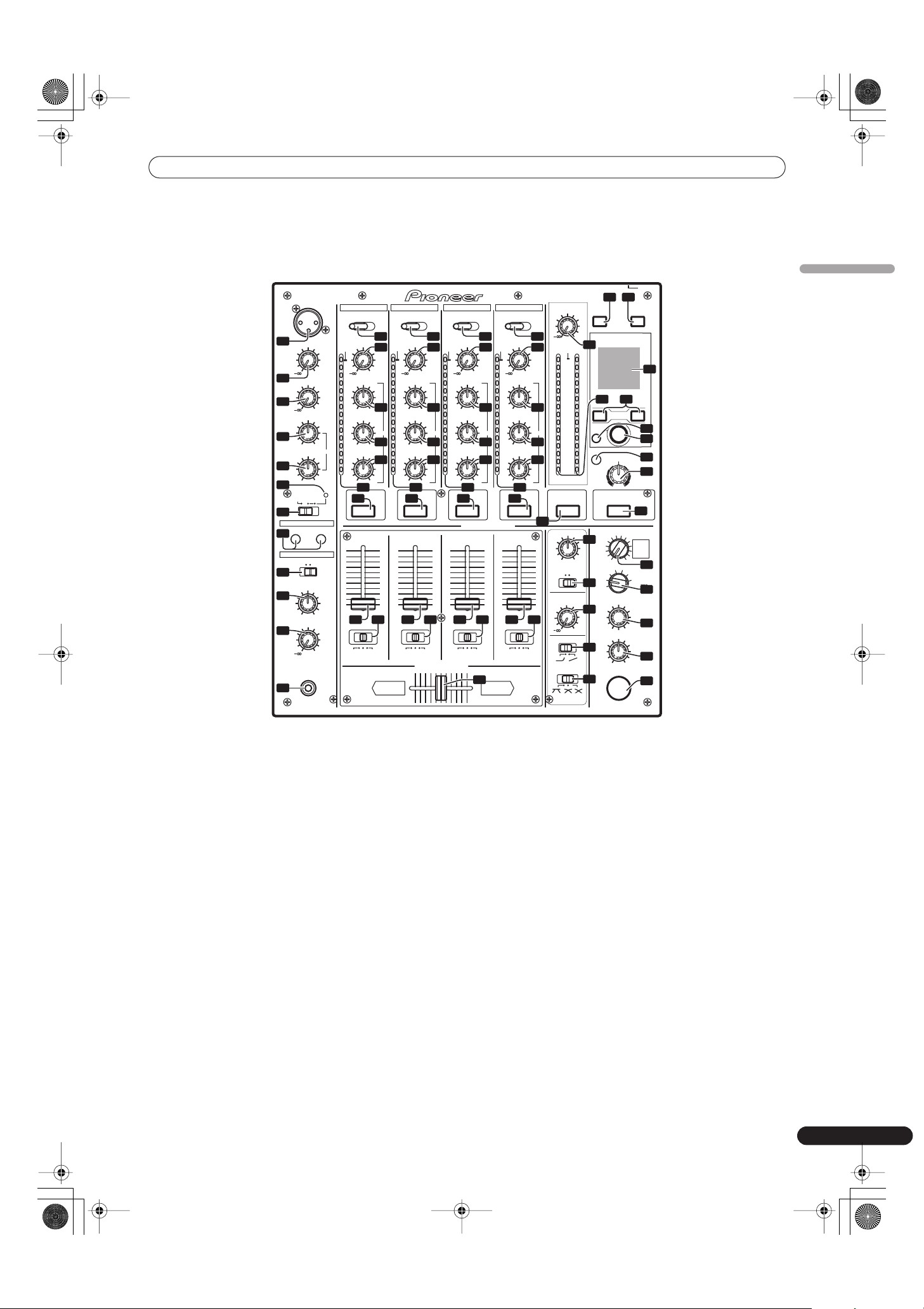
NAMES AND FUNCTIONS OF PARTS
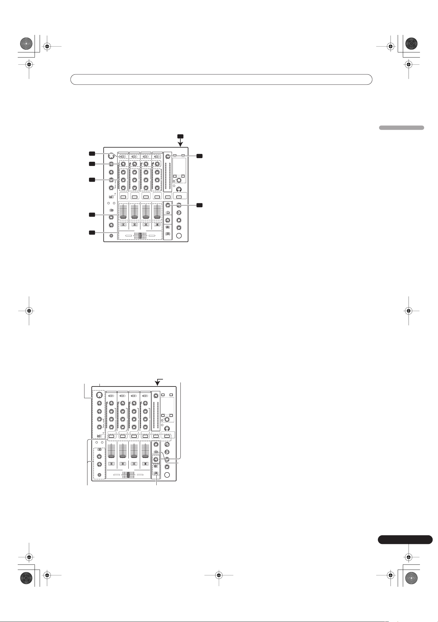
OPERATION PANEL
1 Microphone 1 input jack (MIC 1)
Connect microphone with XLR-type plug.
2 Microphone 1 level control dial (MIC 1 LEVEL)
Use to adjust the volume of microphone 1. (adjustable range –
∞
to
0 dB)
3 Microphone 2 level control dial (MIC 2 LEVEL)
Use to adjust the volume of microphone 2. (adjustable range –
∞
to
0 dB)
4 Microphone equalizer high-range control dial (HI)
Use to adjust the treble (high-range) frequencies of microphones 1
and 2. (adjustable range –12 dB to +12 dB)
5 Microphone equalizer low-range control dial (LOW)
Use to adjust the bass (low-range) frequencies of microphones 1
and 2. (adjustable range –12 dB to +12 dB)
6 Microphone function indicator
Lights when microphone is ON; flashes when
TALK OVER
is ON.
7 Microphone function selector switch (MIC)
OFF:
No microphone sound is output.
ON:
Microphone sound is output normally.
TALK OVER:
Microphone sound is output; when sound is input to a connected
microphone, the TALK OVER function operates and all sound
other than that from the microphone is attenuated by 20 dB.
• When not using the TALK OVER function, it is recommended to
set the switch to the [
OFF
] or [
ON
] position.
8 Channel 1 input selector switch
CD:
Selects
CD
input (line level analog input).
LINE:
Use to select
LINE
input connectors.
9 Channel 2 input selector switch
CD:
Selects
CD
input (line level analog input).
PHONO:
Use to select
PHONO
input connectors (analog turntable input).
10 Channel 3, 4 input selector switch
LINE:
Selects
LINE
input (line level analog input).
PHONO:
Use to select
PHONO
input connectors (analog turntable input).
11 TRIM adjust dial
Use to adjust the input level for each channel. (adjustable range: –
∞
to +9 dB, mid-position is about 0 dB)
12 Channel equalizer high-range adjust dial (HI)
Use to adjust the treble (high-range) frequency sound for each
channel. (adjustable range: –26 dB to +6 dB)
DJM–700
PROFESSIONAL MIXIER
TRIM
+9
TRIM
+9
TRIM
+9
TRIM
+9
0
MID
+6-26
MID
+6-26
MID
+6-26
MID
+6-26
HI
+6-26
HI
+6-26
HI
+6-26
HI
+6-26
LOW
+6-26
LOW
+6-26
LOW
+6-26
LOW
+6-26
FREQUENCY
HPFLPF
FILTER
BALANCE
RL
dB
OVER
10
7
4
2
1
0
–1
–2
–3
–5
–7
–10
–15
–24
dB
OVER
10
7
4
2
1
0
–1
–2
–3
–5
–7
–10
–15
–24
dB
OVER
10
7
4
2
1
0
–1
–2
–3
–5
–7
–10
–15
–24
dB
OVER
10
7
4
2
1
0
–1
–2
–3
–5
–7
–10
–15
–24
dBLR
OVER
10
7
4
2
1
0
–1
–2
–3
–5
–7
–10
–15
–24
EQ EQ EQ EQ
LINECD CD PHONO LINE PHONO LINE PHONO
POWER
MASTER
LEVEL
CH-1 CH-2 CH-3 CH-4
1234
HEADPHONES CUE
MASTER EFFECTS
10
9
8
7
6
5
4
3
2
1
0
10
9
8
7
6
5
4
3
2
1
0
10
9
8
7
6
5
4
3
2
1
0
10
9
8
7
6
5
4
3
2
1
0
A THRU B
AB
A THRU B A THRU B A THRU B
CROSS FADER ASSIGN
BOOTH MONITOR
LEVEL
0
CH FADER
CROSS FADER
AUTO
ON/OFF START/STOP
TAP
BEAT
MIDI
BEAT EFFECTS
LEVEL/DEPTH
TIME
MAX
ON/OFF
MIN
DELAY
1
2
3
4
MIC
CF.A
CF.B
MASTER
TRANS
DOWN
FILTER
UP
FLANGER
REVERSE
PHASER
ROLL
REVERB
CRUSH ROLL
ROBOT
ECHO
SND/RTN
23
FADER START
MIC1
HEADPHONES
MIC1 LEVEL
0
MIC2 LEVEL
0
LEVEL
0
HI
MIC
CH-1 CH-2
OFF ON
TALK
OVER
+12-12
LOW
+12-12
MIXING
MASTERCUE
EQ
MONO SPLIT STEREO
PHONES
MONO STEREO
3
4
5
29
30
23
17
18 19 18 19
18 19 18 19
33 34
20
26
21
6
7
28
31
24 32
36
41
42
40
39
43
38
35
37
22
1
2
16
16
11
13
14
8
12
15
11
13
14
9
12
15
11
13
14
10
12
15
11
13
14
10
12
15
25
27
44
16 16 16 16
01_DJM-700_En.book 9 ページ 2007年7月10日 火曜日 午後8時41分

NAMES AND FUNCTIONS OF PARTS
10
En
13 Channel equalizer mid-range adjust dial (MID)
Use to adjust the mid-range frequency sound for each channel.
(adjustable range: –26 dB to +6 dB)
14 Channel equalizer low-range adjust dial (LOW)
Use to adjust the bass (low-range) frequency sound for each
channel. (adjustable range: –26 dB to +6 dB)
15 Channel level indicator
Displays the current level for each channel, with two-second peak
hold.
16 HEADPHONES CUE buttons/indicators
These buttons are used to select from
1
to
4
,
MASTER
, or
EFFECTS
, to allow you to monitor the desired source through
headphones. If multiple buttons are pressed simultaneously, the
selected audio sources are mixed. Press the button once more to
cancel the selected source. Unselected buttons glow darkly, while
selected source buttons light brightly.
17 Fader start button/indicator (FADER START CH-1, CH-2)
Enables the fader start/back cue function for the channel to which
a DJ CD player is connected. The button lights when set to ON.
When enabled, the operation differs depending on the setting of
the
CROSS FADER ASSIGN
switch.
• When the
CROSS FADER ASSIGN
switch is set to the [
A
] or [
B
]
position, fader start button operation is linked to the operation of
the cross fader (and unlinked to channel fader).
• When the
CROSS FADER ASSIGN
switch is set to the [
THRU
]
position, fader start button operation is linked to the operation of
the channel fader (and unlinked to cross fader).
18 Channel fader lever
Use to adjust sound volumes for each channel. (adjustable range:
–
∞
to 0 dB)
Output is in accordance with the channel fader curve selected
with the
CH FADER
curve switch.
19 CROSS FADER ASSIGN switch
This switch assigns each channel’s output to either right or left
side of the cross fader (if multiple channels are assigned to the
same side, the result will be the combined sum of the channels).
A:
The selected channel is assigned to the cross fader’s A (left) side.
THRU:
The channel fader’s output is sent as is to the master output,
without being passed through the cross fader.
B:
The selected channel is assigned to the cross fader’s B (right) side.
20 Channel fader curve switch (CH FADER)
This switch allows the user to select from two types of channel
fader curve response. This setting is applied equally to channels
1 to 4.
• At the left setting, the curve operates to produce a rapid rise as
the channel fader approaches its distant position.
• At the right setting, the curve operates to produce an even,
neutral rise throughout the channel fader’s movement.
21 Cross fader curve switch (CROSS FADER)
This switch allows the user to select from three types of cross fader
curve response.
• At the left setting, the curve produces a rapid signal rise. (As
soon as the cross fader lever leaves the [
A
] side, the [
B
] channel
sound is produced.)
• At the right setting, the curve operates to produce an even,
neutral rise throughout the cross fader’s movement.
• At the middle setting, an intermediate curve is produced,
midway between the two curves noted above.
22 Cross fader lever
Outputs sound assigned to [
A
] and [
B
] sides in accordance with
setting of the
CROSS FADER ASSIGN
switch, and subject to the
cross fader curve selected with the
CROSS FADER
curve switch.
23 Master output level dial (MASTER LEVEL)
Use to adjust the master output level. (adjustable range: –
∞
to
0 dB)
The master output is the sum combination of the sound from
channels set to [
THRU
] with the
CROSS FADER ASSIGN
switch;
the signal passed through the cross fader; and the signals from
microphone 1 and microphone 2 (if the effect selector is set to
[
SND/RTN
], the
RETURN
input is also added).
24 Master level indicator (MASTER L, R)
These segment indicators display the output level from L and R
channels. The indicators have a two-second peak hold.
25 Master balance dial (BALANCE)
Use to adjust the L/R channel balance for master output, booth
monitor output, recording output, and digital output.
26 Master output MONO/STEREO selector switch
When set to the [
MONO
] position, master output, booth monitor
output, recording output, digital output are all produced in L+R
monaural.
27 BOOTH MONITOR LEVEL control dial
This dial is used to adjust the booth monitor output volume.
The volume can be adjusted independently of the master output
level. (adjustable range: –
∞
to 0 dB)
28 Headphones output switch (MONO SPLIT/STEREO)
MONO SPLIT:
When
HEADPHONES CUE
(
1
,
2
,
3
,
4
or
EFFECTS
) button is
selected, the selected audio is output to the L channel. When
HEADPHONES CUE
(
MASTER
) button is selected, the master
audio is output from the R channel.
STEREO:
The audio source selected with the
HEADPHONES CUE
button is
output in stereo.
29 Headphones mixing dial (MIXING)
When rotated clockwise (toward [
MASTER
]), the master output
audio is produced at the headphones (only when [
MASTER
] has
been selected with the
HEADPHONES CUE
button); when rotated
counterclockwise (toward [
CUE
]), the headphones output
becomes the mixture of the effect monitor and the channel
selected with the
HEADPHONES CUE
button.
In the middle position, the audio from [
MASTER
] and [
CUE
] will be
output.
30 Headphones level adjust dial (LEVEL)
Adjusts the output level of the headphones jack. (adjustable range:
–
∞
to 0 dB)
01_DJM-700_En.book 10 ページ 2007年7月10日 火曜日 午後8時41分
NAMES AND FUNCTIONS OF PARTS
11
En
English
31 Headphones jack (PHONES)
Connect to headphones equipped with phone-type jack.
32 Beat select buttons (
BEAT
)
(Beat up):Doubles the calculated BPM.
(Beat down):Halves the calculated BPM.
(P. 18)
• Some effects can be set for
“3/4”
.
With some effects, these are used for functions other than setting
the beat.
33 MIDI ON/OFF button
Sets MIDI output function (not including timing lock) to ON/OFF.
When power is first turned ON, automatically defaults to OFF.
34 MIDI start/stop button (MIDI START/STOP)
Outputs START/STOP signal for MIDI control function (see P. 21).
When this control is enabled, the [
MIDI START (STOP)
] message
appears for two seconds on the display.
MIDI SNAP SHOT:
When the
MIDI START/STOP
button is held depressed, a snapshot
is sent to the external MIDI component.
35 BPM measuring mode button (AUTO)
Switches between the BPM measuring modes AUTO and TAP.
When [
AUTO
] indicator on the display is lighted, the BPM will be
measured automatically.
36
TAP
button
The BPM is calculated from the intervals at which the
TAP
button
is struck. If the
TAP
button is pressed in the AUTO mode, the mode
automatically switches to the TAP mode (manual input).
37 MANUAL/EFFECT Frequency filter button
Use to switch between manual filter and effect frequency filter.
When power is first turned ON, defaults to effect frequency filter
and the button indicator lights. When manual filter is selected, the
button indicator does not light.
38 Manual filter adjust dial (FREQUENCY)
Use to adjust the cutoff frequency of the selected filter.
39 Effect selector (DELAY, ECHO, TRANS, FILTER, FLANGER,
PHASER, REVERB, ROBOT (ROBOT VOCODER), CRUSH, ROLL,
REVERSE (REVERSE ROLL), UP (UP ROLL), DOWN (DOWN
ROLL), SND/RTN (SEND/RETURN))
Use to select desired type of effect (P. 16).
When using an external effector connected to the
SEND
and
RETURN
connectors, set to the [
SND/RTN
] position.
40 Effect channel selector (1, 2, 3, 4, MIC, CF.A, CF.B, MASTER)
Use to select the channel to which effects are applied (P. 18).
When [
MIC
] is selected, effects are applied to both microphone 1
and microphone 2.
41 Effect parameter 1 dial [TIME (PARAMETER 1)]
Adjusts time parameter for selected effect (P. 18, 20) (With some
effects, this is used for adjustments other than time parameters.)
• If the
TIME
dial is rotated while depressing the
TAP
button,
direct BPM can be set manually.
• If the
TIME
dial is rotated while holding the
TAP
button and
AUTO/TAP
buttons depressed, the BPM can be set in 0.1 units.
42 Effect parameter 2 dial [LEVEL/DEPTH (PARAMETER 2)]
Adjusts quantitative parameters for selected effect (P. 18, 20).
43 Effect button/indicator (ON/OFF)
Sets selected effect ON/OFF (P. 18). When power is first turned
ON, defaults to effect OFF. When set to effect OFF, the button
indicator lights. When effects are enabled (ON), the button
flashes.
44 Display
See the following section for details.
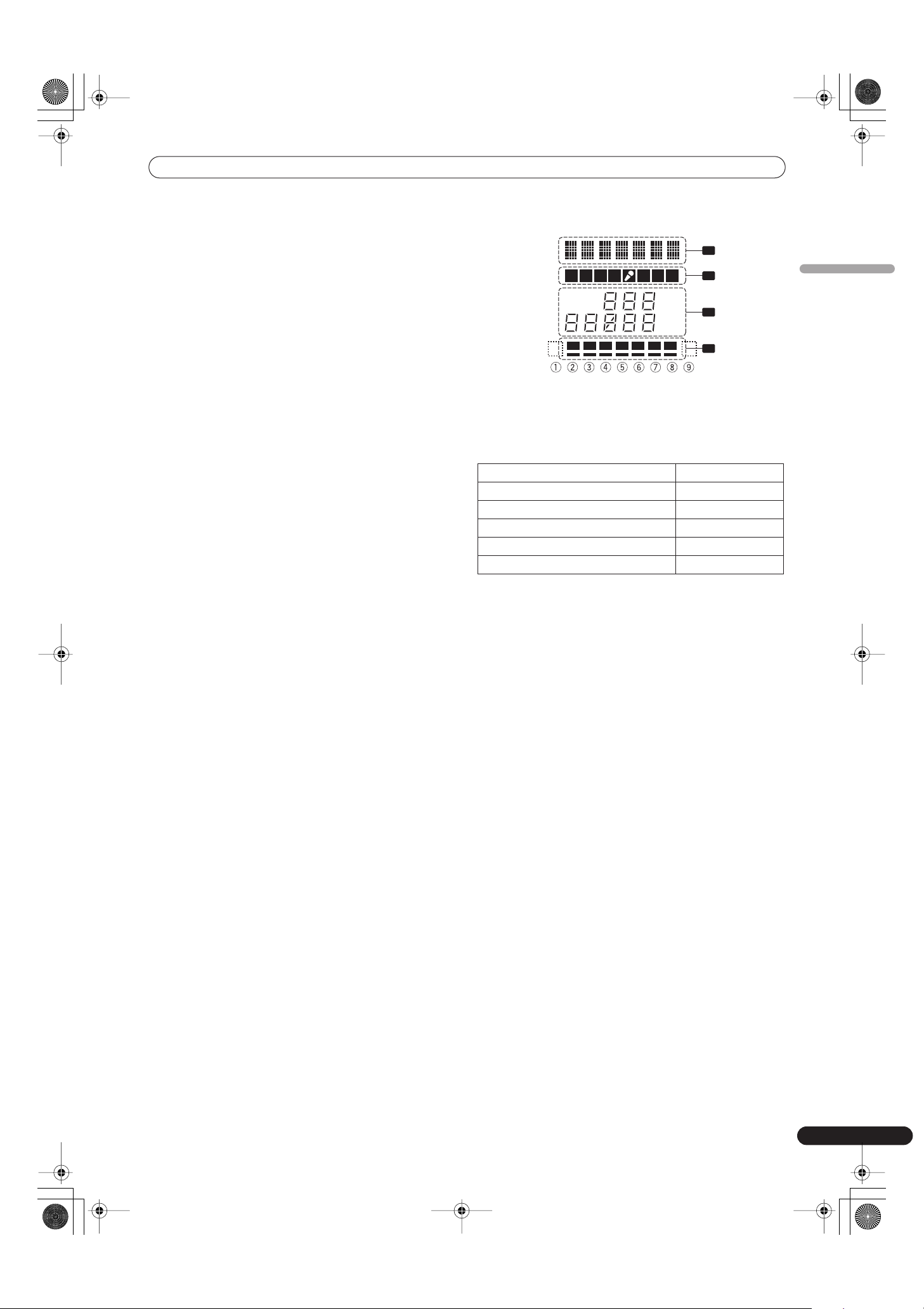
DISPLAY SECTION
1 Effects display section
Text display (7 characters) displays effect name as shown in
accompanying table. Also, when one of the change operations is
performed as noted in the table, the corresponding characters are
displayed for two seconds, after which the display returns to the
original effect name.
2 Channel select display section
Lights position selected by effect channel selector.
3 Parameter display section
AUTO/TAP:
[
AUTO
] lights when the BPM measuring mode is set to AUTO, and
[
TAP
] lights when the BPM measuring mode is set to manual
(TAP).
BPM counter display
(3 digits)
:
In AUTO mode, displays the automatically detected BPM value. If
the BPM count cannot be detected automatically, the display will
flash at the previously detected value. In manual (TAP) mode,
displays the BPM value designated by TAP input, etc.
BPM:
Lights constantly.
MIDI:
Indicates status of MIDI output function ON/OFF.
• Lights when MIDI output function is ON.
• Not lighted when MIDI output function is OFF.
Parameter 1 display
(5 digits)
:
Displays parameters designated for each effect. When the beat
select buttons (
BEAT
,
) are pressed, the corresponding beat
multiple change is displayed for two seconds. If the beat select
buttons (
BEAT
,
) are used to designate a value outside the
parameter range, the current number will flash but will not
change.
Unit Display (%/ms):
Lights in accordance with the unit used for each effect.
Switching Operation Display
At MIDI start START
At MIDI stop STOP
MIDI snapshot SNAP
When MIDI output function is ON MIDI On
When MIDI output function is OFF MIDIOff
A B M
MIDI
BPM
%
mS
123 4
AUTO
TAP
1
2
3
4
01_DJM-700_En.book 11 ページ 2007年7月10日 火曜日 午後8時41分
NAMES AND FUNCTIONS OF PARTS
12
En
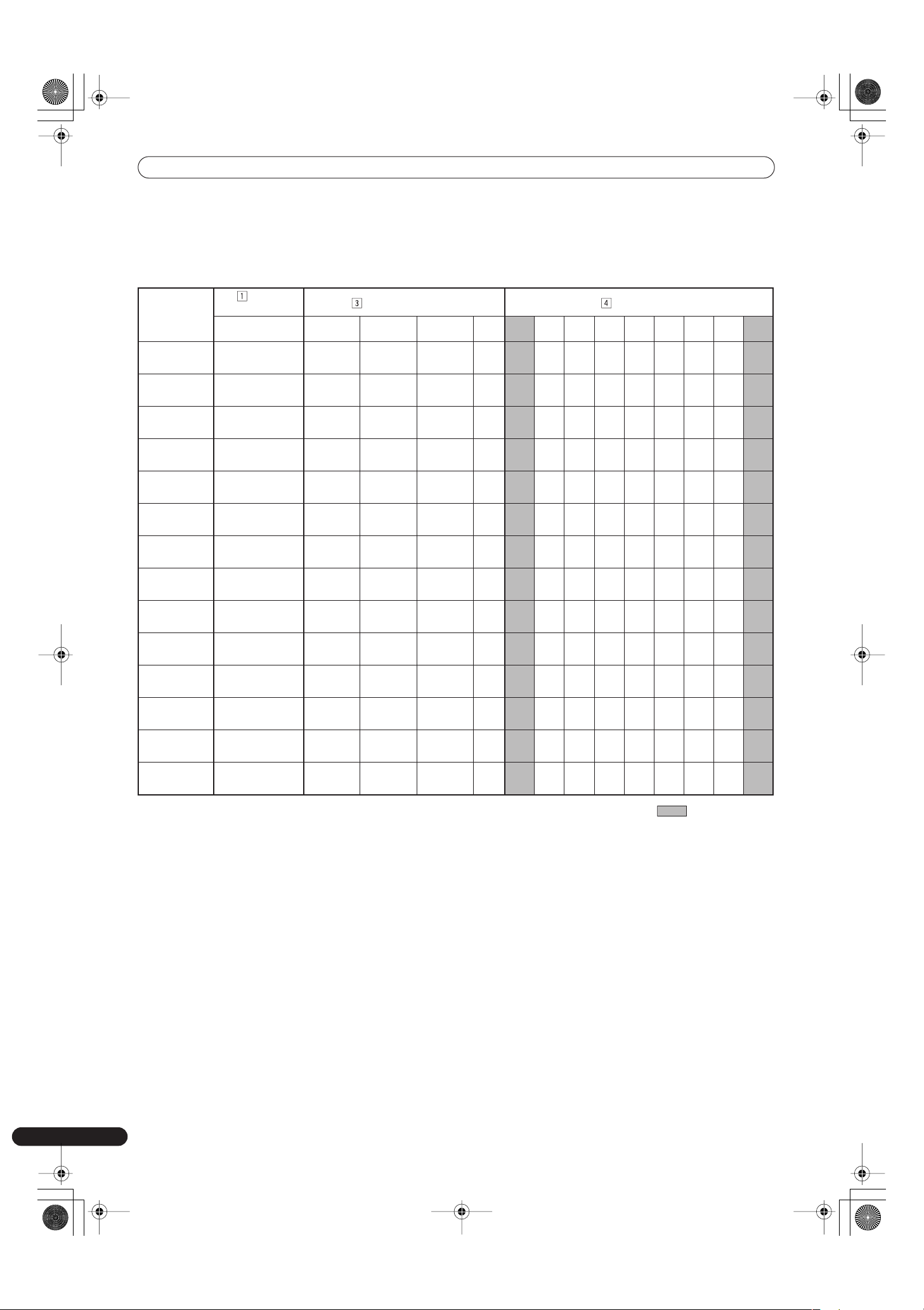
4 Beat display section
Displays the location of parameter 1 relative to BPM (1/1 beat). The
lower row is lighted constantly. When the parameter 1 location
approaches a threshold value, the corresponding indicator is
lighted. When the parameter 1 is between threshold values, the
indicator flashes. Although the display includes seven actual
indicators, the values of the two ends can also be considered to
represent indicators, with the result that nine positions can be
logically assumed. When the values are at the two ends, no
indicators light.
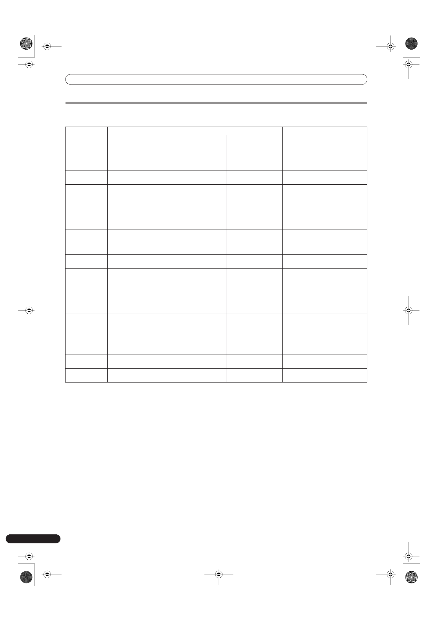
Shaded items are not displayed.
Effect
selector
Effect
display
Parameter display Beat display
Effect name
Minimum
value
Maximum
value
Default Unit
➀➁➂➃➄➅➆➇
➈
DELAY DELAY 1 4 000 500 ms 1/8 1/4 1/2 3/4 1/1 2/1 4/1 8/1 16/1
ECHO ECHO 1 4 000 500 ms
1/8 1/4 1/2 3/4 1/1 2/1 4/1 8/1 16/1
TRANS TRANS 10 16 000 500 ms
1/16 1/8 1/4 1/2 1/1 2/1 4/1 8/1 16/1
FILTER FILTER 10 32 000 2 000 ms
1/4 1/2 1/1 2/1 4/1 8/1 16/1 32/1 64/1
FLANGER FLANGER 10 32 000 2 000 ms
1/4 1/2 1/1 2/1 4/1 8/1 16/1 32/1 64/1
PHASER PHASER 10 32 000 2 000 ms
1/4 1/2 1/1 2/1 4/1 8/1 16/1 32/1 64/1
REVERB REVERB 1 100 50 %
10 20 30 40 50 60 70 80 90
ROBOT ROBOT –100 100 0 %
—
–100
–66 –50 0 26 50 100 —
CRUSH CRUSH 10 32 000 2 000 ms
1/4 1/2 1/1 2/1 4/1 8/1 16/1 32/1 64/1
ROLL ROLL 10 4 000 500 ms
1/16 1/8 1/4 1/2 1/1 2/1 4/1 8/1 16/1
REV ROLL REVROLL 10 4 000 500 ms
1/16 1/8 1/4 1/2 1/1 2/1 4/1 8/1 16/1
UP ROLL UP ROLL 10 4 000 500 ms
1/16 1/8 1/4 1/2 1/1 2/1 4/1 8/1 16/1
DOWN ROLL DWNROLL 10 4 000 500 ms
1/16 1/8 1/4 1/2 1/1 2/1 4/1 8/1 16/1
SND/RTN SND/RTN
01_DJM-700_En.book 12 ページ 2007年7月10日 火曜日 午後8時41分
MIXER OPERATIONS
13
En
English
MIXER OPERATIONS
BASIC OPERATIONS
1 Set rear panel POWER switch to ON.
2 Set the input selector switch for the desired channel to
choose the connected component.
• CH1: Set to [
CD
] or [
LINE
].
CH2: Set to [
CD
] or [
PHONO
].
CH3/4: Set to [
LINE
] or [
PHONO
].
3 Use the TRIM dial to adjust the input level.
4 Use the channel equalizer dials (HI, MID, LOW) to adjust the
tone.
5 Use the channel fader lever to adjust the sound volume of
the selected channel.
6 To use the cross fader on the selected channel, set the CROSS
FADER ASSIGN switch to either cross fader channel A or
channel B, and operate the cross fader lever.
• When not using the cross fader, set the
CROSS FADER
ASSIGN
switch to [
THRU
].
7 Use the MASTER LEVEL dial to adjust the overall sound
volume.
8 Use the BALANCE dial to adjust the sound balance between
right and left.
[Selecting Stereo or Monaural]
When the
MONO/STEREO
switch is set to [
MONO
], the master
output becomes a monaural combination of L+R channels.
[Microphone Input]
1 To use a microphone, set the MIC switch to [ON] or [TALK
OVER].
• When the switch is set to [
TALK OVER
], any time a sound of
over –15 dB is detected by the microphone, the output for all
sound sources other than the microphone are attenuated by
20 dB.
2 Use the MIC 1 LEVEL dial to adjust the sound volume of
MIC 1, and use the MIC 2 LEVEL dial to adjust the sound
volume of MIC 2.
3 Use the microphone equalizer dials (HI, LOW) to adjust the
tone of the microphone sound.
• The microphone equalizer function operates simultaneously
on microphone 1 and 2.
[Booth Monitor Output]
1 Use the BOOTH MONITOR LEVEL dial to adjust the sound
volume.
• The
BOOTH MONITOR LEVEL
dial can be used to adjust the
sound volume independently of the
MASTER LEVEL
dial.
[Headphones Output]
1 Use the HEADPHONES CUE buttons (channels 1 to 4,
MASTER, EFFECTS) to select the source.
• The selected
HEADPHONES CUE
button lights brightly.
2 Set the headphones (MONO SPLIT/STEREO) switch.
• When
HEADPHONES CUE
(
1
,
2
,
3
,
4
or
EFFECTS
) button is
selected, the selected audio is output to the L channel.
When
HEADPHONES CUE
(
MASTER
) button is selected, the
master audio is output from the R channel.
• When set to the [
STEREO
] position, the sound
corresponding to the selected
HEADPHONES CUE
button is
output in stereo.
3 When [MONO SPLIT] is selected, use the MIXING dial to
adjust the balance of sound between the left channel (sound
selected with the HEADPHONES CUE button), and the right
channel (the master sound – but only when the
HEADPHONES CUE button for the [MASTER] is ON).
• When the
MIXING
dial is rotated clockwise (toward
[
MASTER
]), the master output (only when the
HEADPHONES CUE
button for the [
MASTER
] is ON)
increases; when rotated counterclockwise (toward [
CUE
]),
the sound selected with the
HEADPHONES CUE
button is
output.
4 Use the LEVEL dial to adjust the headphones’ sound volume.
2
1
8
7
3
4
5
6
POWER
TRIM
HI, MID, LOW
BALANCE
MASTER
LEVEL
Microphone input Booth monitor output
Headphones output Fader curve
MONO/
STEREO
01_DJM-700_En.book 13 ページ 2007年7月10日 火曜日 午後8時41分
MIXER OPERATIONS
14
En
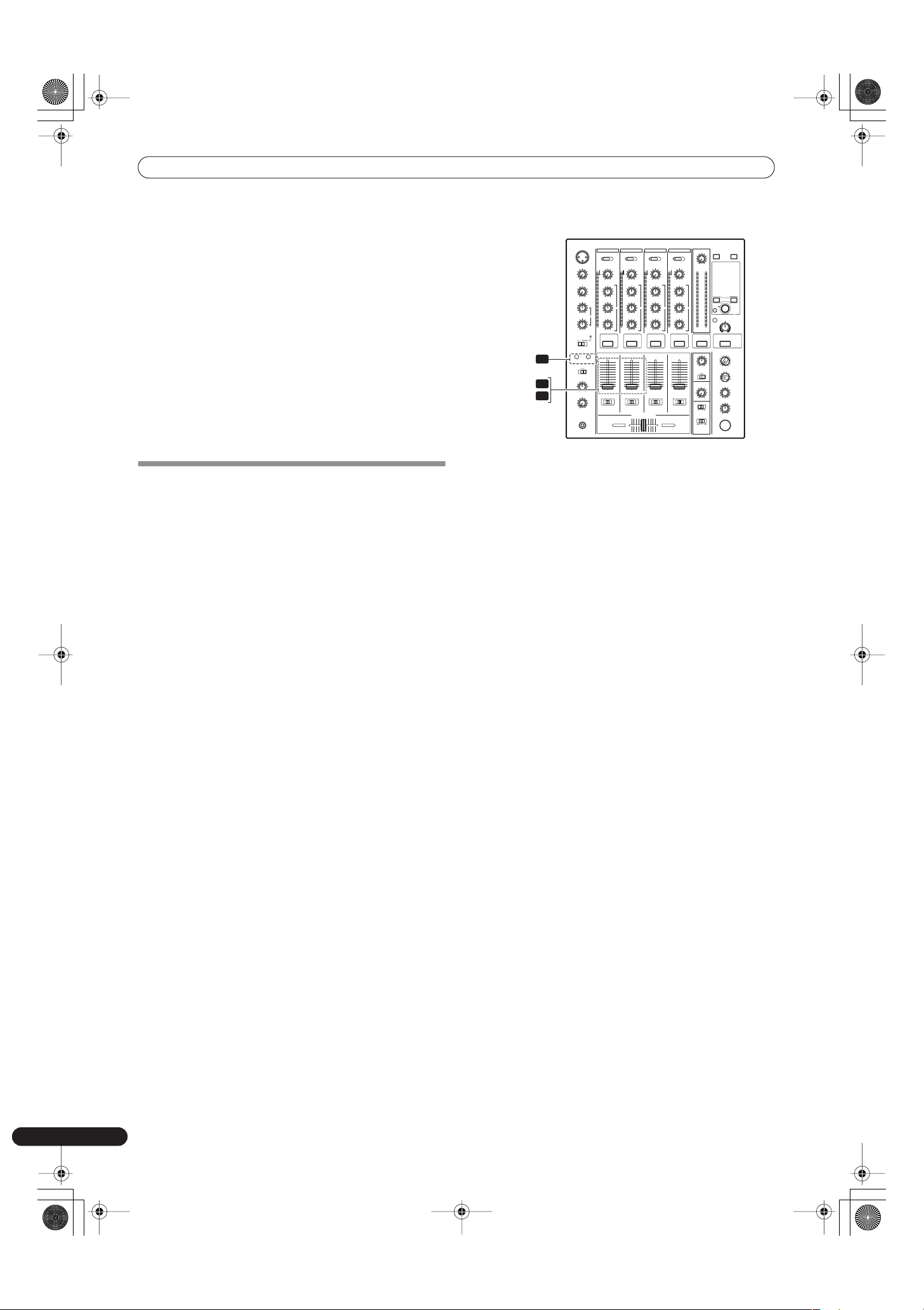
[Fader Curve Selection]
Select sound-volume curve corresponding to fader operation.
Use the CH FADER switch to select the desired channel fader
response curve.
• At the left setting, the curve operates to produce a rapid rise
as the channel fader approaches its distant position.
• At the right setting, the curve operates to produce an even,
neutral rise throughout the channel fader’s movement.
• This setting applies equally to channels 1 to 4.
Use the CROSS FADER curve switch to select the cross fader
curve response.
• At the left setting, the curve produces a rapid signal rise. (As
soon as the cross fader lever leaves the [
A
] side, the [
B
]
channel sound is produced.)
• At the right setting, the curve operates to produce an even,
neutral rise throughout the cross fader’s movement.
• At the middle setting, an intermediate curve is produced,
midway between the two curves noted above.
• This setting produces equal curve effects for both sides A
and B.
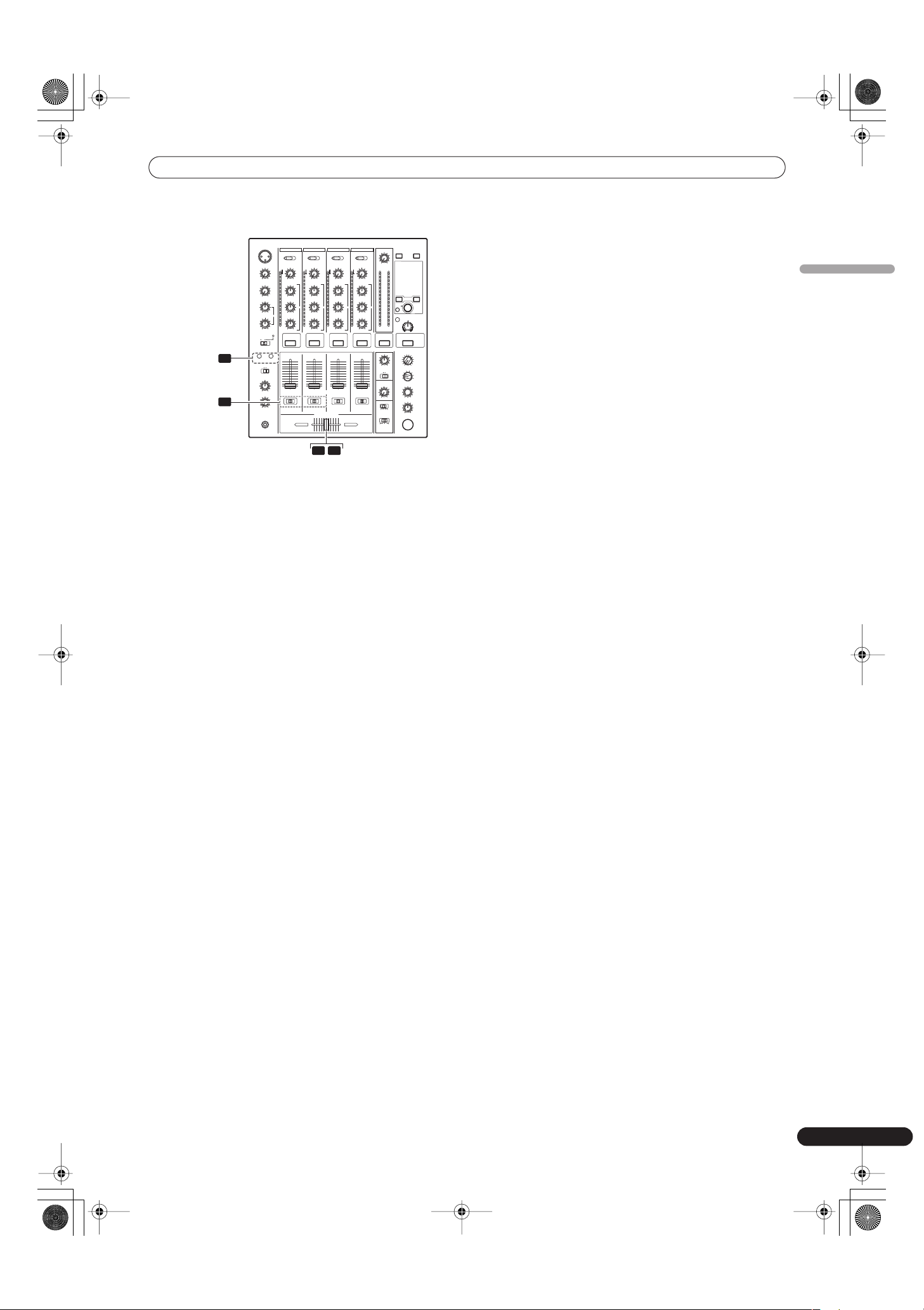
FADER START FUNCTION
By connecting the optional Pioneer DJ CD Player control cable,
the channel fader and cross fader can be used to start CD
playback.
When the mixer’s channel fader lever or cross fader lever are
moved, the CD player is released from the pause mode and
automatically –and instantly – begins playback of the selected
track. Also, when the fader lever is returned to its original position,
the CD player returns to its cue point (back cue), thus allowing
“sampler” type play.
Cross fader start play and back cue play
When the CD player assigned to cross fader channel A is set to
standby at a cue point, moving the cross fader lever from the right
(B) side toward the left (A) side automatically starts play on the
channel A CD player.
When the cross fader lever reaches the left (A) side, the CD player
assigned to channel B goes to back cue (returns to cue point).
Also, when the CD player assigned to channel B is set to standby
at a cue point, moving the cross fader lever from the left (A) side to
the right (B) side automatically starts playback on the channel B
CD player. When the cross fader lever reaches the right (B) side,
the CD player assigned to channel A goes to back cue (returns to
cue point).
• The back cue is performed even if the input selector switch is not
set to [
CD
] or [
LINE
].
[Using the Channel Fader to Start Playback]
1 Press the FADER START button for the channel (1, 2)
connected to the CD player you wish to control.
• The button for the selected channel lights.
2 Set the channel fader lever to “0”.
3 Set the CD player to the desired cue point, and engage cue
point standby.
• If a cue point has already been set, it is not necessary to set
the CD player to standby at the cue point.
4 At the instant you wish to start playback, move the channel
fader lever.
• CD player begins playback.
• After playback has begun, if the channel fader lever is
returned to the [
0
] position, the CD player returns to the cue
point and re-enters standby mode (back cue).
• Playback control is possible with the channel fader only with the
CROSS FADER ASSIGN
switch is set to [
THRU
].
1
2
4
FADER
START
1, 2
01_DJM-700_En.book 14 ページ 2007年7月10日 火曜日 午後8時41分
MIXER OPERATIONS
15
En
English
[Using the Cross Fader to Start Playback]
1 Press the FADER START button for the channel (1, 2)
connected to the CD player you wish to control.
• The button for the selected channel lights.
2 Set the CROSS FADER ASSIGN switch for the selected channel
to [A] or [B].
• Select [
A
] to assign to cross fader channel A (left side).
• Select [
B
] to assign to cross fader channel B (right side).
3 Move the cross fader lever to the full opposite side away
from the CD player you wish to start.
4 Set the CD player to the desired cue point, and engage cue
point standby.
• If a cue point has already been set, it is not necessary to set
the CD player to standby at the cue point.
5 At the instant you wish to start playback, move the cross
fader lever.
• CD player begins playback.
• After playback has begun, if the cross fader lever is moved
fully to the opposite side, the CD player assigned to the
opposite side channel will return to the cue point and enter
standby mode (back cue).
1
2
3 5
FADER
START
1, 2
CROSS
FADER
ASSIGN
A / THRU / B
01_DJM-700_En.book 15 ページ 2007年7月10日 火曜日 午後8時41分
EFFECT FUNCTIONS
16
En
EFFECT FUNCTIONS
This unit can produce a total of 15 basic beat effects (including
SND/RTN) through beat effects linked to the BPM and manual
filters or effect frequency filters linked to the
FREQUENCY
dial.
Additionally, by adjusting the parameters for each effects, a wide
range of effects can be produced.
A wide variety of beat effects can be created by adjusting the
temporal parameter through the
TIME
dial (Parameter 1) as well
as the quantitative parameter through the
LEVEL/DEPTH
dial
(Parameter 2).
A low-pass filter effect or high-pass filter effect can be created with
the manual filter or effect frequency filter depending on the
positioning of the
FREQUENCY
dial. Additionally, by combining
beat effects with the manual filter or effect frequency filter, a wide
range of effects can be created.
TYPES OF BEAT EFFECTS
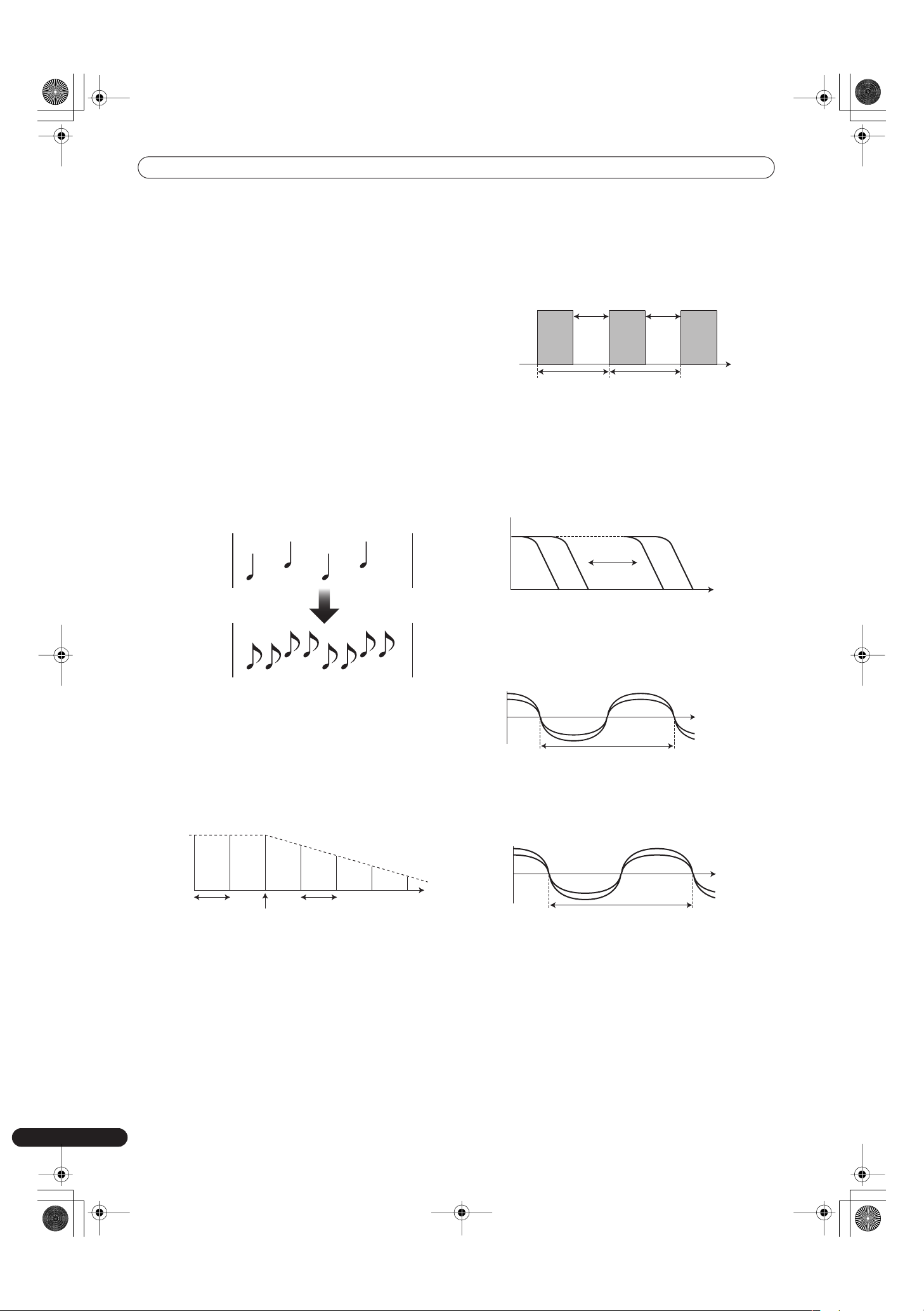
1 DELAY (One repeat sound)
This function allows a delay sound with beat of 1/8, 1/4, 1/2, 3/4,
1/1, 2/1, 4/1, 8/1, or 16/1 to be added quickly and simply. For
example, When a 1/2 beat delay sound is added, four beats
become eight beats. Also, by adding a 3/4 beat delay sound, the
rhythm becomes syncopated.
2 ECHO (Multiple repeat sounds)
This function allows an echo sound with beat of 1/8, 1/4, 1/2,
3/4, 1/1, 2/1, 4/1, 8/1, or 16/1 to be added quickly and simply.
For example, when a 1/1 beat echo sound is used to cutoff the
input sound, a sound in synch with the beat is repeated
together with fadeout.
Also, by adding a 1/1 beat echo to the microphone, the
microphone sound repeats in synch with the music beat.
If a 1/1 beat echo is applied to the vocal portion of a track, the
song takes on an effect reminiscent of a “round”.
3 Auto TRANS
In units of 1/16, 1/8, 1/4, 1/2, 1/1, 2/1, 4/1, 8/1, or 16/1 beat, the
sound is automatically cut in synch with the rhythm.
4 FILTER
In units of 1/4, 1/2, 1/1, 2/1, 4/1, 8/1, 16/1, 32/1, or 64/1 beat, the
filter frequency is moved, greatly changing the sound
coloration.
5 FLANGER
In units of 1/4, 1/2, 1/1, 2/1, 4/1, 8/1, 16/1, 32/1, or 64/1 beat,
1 cycle of flanger effect is produced quickly and easily.
6 PHASER
In units of 1/4, 1/2, 1/1, 2/1, 4/1, 8/1, 16/1, 32/1, or 64/1 beat,
1 cycle of phaser effect is produced quickly and easily.
Example
Original
(4 beats)
1/2 delay
(8 beats)
Example
Original
(4 beats)
1/2 delay
(8 beats)
Example
1 beat
Cuts input
sound
1 beat
Example
Cut
Time
Cut
1 cycle =1/16, 1/8, 1/4, 1/2, 1/1, 2/1,
4/1, 8/1, or 16/1 beat
Example
Frequency
1 c
y
cle =1/4, 1/2, 1/1, 2/1, 4/1, 8/1, 16/1, 32/1, or 64/1 beat
Example
1 c
y
cle =1/4, 1/2, 1/1, 2/1, 4/1, 8/1, 16/1, 32/1, or 64/1 beat
Short delay
Example
Phase shift
1 c
y
cle = 1/4, 1/2, 1/1, 2/1, 4/1, 8/1, 16/1, 32/1, or 64/1 beat
01_DJM-700_En.book 16 ページ 2007年7月10日 火曜日 午後8時41分
EFFECT FUNCTIONS
17
En
English
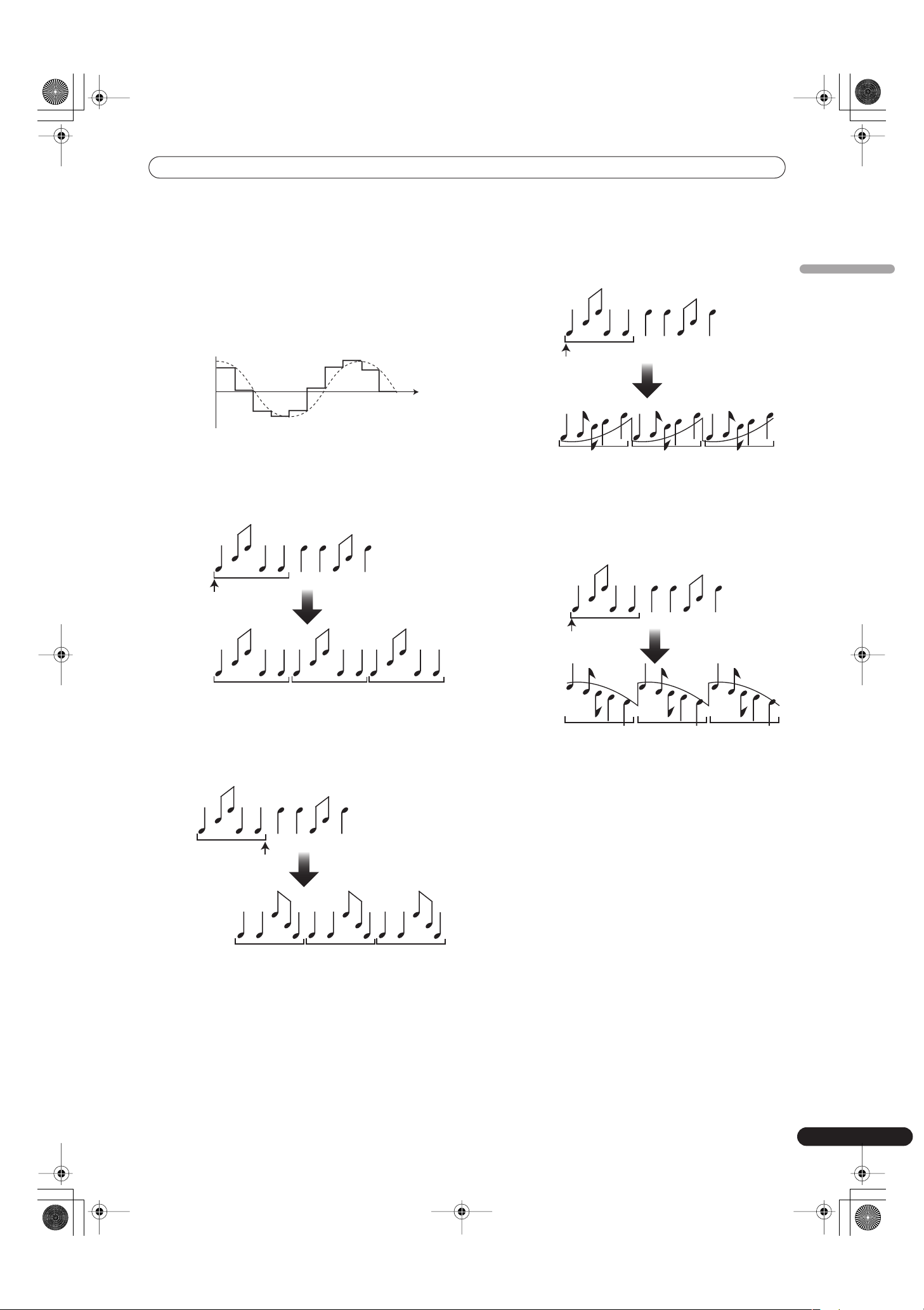
7 REVERB
Produces reverberation effect.
8 ROBOT
Generates sound effect resembling that produced by a robot.
When ROBOT is applied to microphone sound, a voice-
changer effect is produced.
9 CRUSH
Allows rapid creation of cyclically changing “crush sound
effect” in beats of 1/4, 1/2, 1/1, 2/1, 4/1, 8/1, 16/1, 32/1, or 64/1.
10 ROLL
Records sounds at 1/16, 1/8, 1/4, 1/2, 1/1, 2/1, 4/1, 8/1, 16/1
beats and plays them repeatedly.
11 REVERSE ROLL
Records sounds at 1/16, 1/8, 1/4, 1/2, 1/1, 2/1, 4/1, 8/1, 16/1
beats and repeats them but in reverse order.
12 UP ROLL
Records sounds at 1/16, 1/8, 1/4, 1/2, 1/1, 2/1, 4/1, 8/1, 16/1
beats, and plays them repeatedly while continuously raising
their pitch/key.
13 DOWN ROLL
Records sounds at 1/16, 1/8, 1/4, 1/2, 1/1, 2/1, 4/1, 8/1, 16/1
beats, and plays them repeatedly while continuously lowering
their pitch/key.
14 SEND/RETURN
By connecting a sampler or effector, a wide variety of other
effects can be created.
Example
Time
1 c
y
cle = 1/4, 1/2, 1/1, 2/1, 4/1, 8/1, 16/1, 32/1, or 64/1 beat
Example
Repeat
Original
1/1 roll
Effect ON
Example
Reversed repeat
Original
1/1
reverse roll
Effect ON
Example
Key rises and repeats
Original
1/1 UP ROLL
Effect ON
Example
Key lowers and repeats
Original
1/1 DOWN ROLL
Effect ON
01_DJM-700_En.book 17 ページ 2007年7月10日 火曜日 午後8時41分

EFFECT FUNCTIONS
18
En
PRODUCING BEAT EFFECTS
Beat effects allow the instant setting of effect times in synch with
the BPM (beats per minute), thus allowing the production of a
wide variety of effects in synch with the current rhythm, even
during live performances.
1 Set BPM measuring mode to AUTO to measure BPM (beats
per minute).
The BPM of the input music signal is detected automatically.
Whenever power is first turned ON, the function defaults to the
[
AUTO
] mode.
• In the event the track’s BPM cannot be detected
automatically, the display’s BPM counter will flash.
• Measurable range: BPM=70 to 180.
It may not be possible to measure some tracks
accurately.
In this case, press the
TAP
button and input the beat
manually.
[Using the TAP Button for Manual BPM Input]
If the
TAP
button is tapped two times or more in synch with
beat (1/4 notes), the BPM will be recorded as the average value
recorded during that interval.
• When BPM mode is set to [
AUTO
], tapping the
TAP
button
will cause the BPM mode to change to the TAP mode, and
the interval at which the
TAP
button is pressed will be
measured.
• When the BPM is set via the
TAP
button, the beat multiple
becomes “
1/1
” (or “
4/1
”, depending on the effect selected),
and the time for 1 beat (1/4 notes) or 4 beats will be set as
the effect time.
• If the
TIME
dial is rotated while depressing the
TAP
button,
direct BPM can be set manually.
If the
TIME
dial is rotated while holding the
TAP
button and
AUTO
buttons depressed, the BPM can be set in 0.1 units.
2 Set the effect selector to the desired effect.
• The display will show the name of the selected effect.
• See P. 16 to 17 for details regarding the various effects.
3 Set the effect channel selector to the channel you wish to
apply the effect to.
• The selected channel lights in the display’s channel name
area.
• If [
MIC
] is selected, the effect will be applied to both
microphone 1 and microphone 2.
4 Press the BEAT button (
,
) to select the beat multiple to
which the effect is to be synchronized.
• When
is pressed, the beat count calculated from the BPM
is doubled, and when
is pressed, the beat count
calculated from the BPM is halved (some effects also allow
“
3/4
” setting).
• The multiple of the selected beat (parameter 1 position) is
displayed in seven sections on the display (see P. 12).
• The effect time corresponding to the beat’s multiple is set
automatically.
Example: When BPM = 120
1/1 = 500 ms
1/2 = 250 ms
2/1 = 1 000 ms
5 Set the ON/OFF button to ON to enable the effect.
• Each time the button is pressed, the effect alternates ON/
OFF (whenever power is first turned ON, the function
defaults to OFF).
• The
ON/OFF
button flashes when the effect is ON.
Parameter 1
Rotating the
TIME
(
PARAMETER 1
) dial adjusts the temporal
parameter (time) for the selected effect. (With some effects, this is
used for adjustments other than time parameters.)
See P. 20 for details regarding the effect on parameter 1 of rotating
the
TIME
(
PARAMETER 1
) dial.
Parameter 2
Rotating the
LEVEL/DEPTH
(
PARAMETER 2
) dial adjusts the
quantitative parameter for the selected effect.
See P. 20 for details regarding the effect on parameter 2 of rotating
the
LEVEL/DEPTH
(
PARAMETER 2
) dial.
A BM
MIDI
BPM
%
mS
1 2 34
AUTO
TAP
Display example
Effect Name: DELAY
Effect Channel Select: CH 1
BPM value: 120 BPM
Parameter 1: 500 ms
Beat multiple: 1/1
1
4
2
3
5
TAP
AUTO
ON/OFF
TIME
LEVEL/DEPTH
BEAT 2, 3
01_DJM-700_En.book 18 ページ 2007年7月10日 火曜日 午後8時41分
EFFECT FUNCTIONS
19
En
English
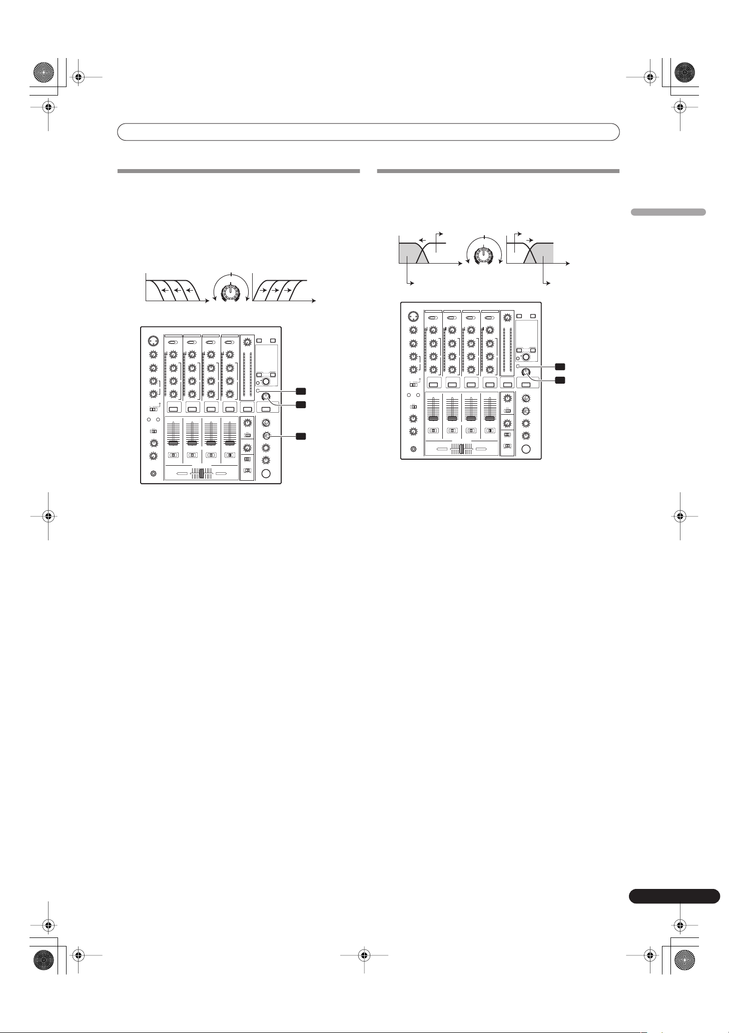
MANUAL FILTER OPERATION
1 MANUAL FILTER
The filter frequency is shifted, resulting in strong changes to
the tone.
Rotating the dial to the right produces high-pass filter effects,
while rotating the dial to the left produces low-pass filter
effects.
The manual effecter is linked to the
FREQUENCY
dial. The output
sounds of the manual effecter become the input sounds for the
beat effect.
• When the beat effect type is set to ROLL, REVERSE ROLL, UP
ROLL, or DOWN ROLL, the beat effect’s output sound becomes
the input sound for the manual effecter.
1 Press the FILTER button so that it flashes.
• Confirm that the
FILTER
button flashes steadily.
• When it lights, press the button so that it flashes. Each time
the button is pressed, it alternates between flashing and
lighting steadily.
• When power is first turned ON, defaults to steadily lighted.
2 Use the effect channel select switch to choose the channel to
which you wish to apply the effects.
• The name of the selected channel will appear in the display’s
channel name section.
• When [
MIC
] is selected, the effect will be applied to both
microphone 1 and microphone 2.
3 Use the FREQUENCY dial to adjust the filter’s cutoff
frequency.
• Rotate counterclockwise to apply a low-pass filter.
• Rotate clockwise to apply a high-pass filter.
EFFECT FREQUENCY FILTER OPERATION
1 Effect frequency filter
Sets the filter’s cutoff frequency, allowing the beat effect to be
applied to a desired frequency band alone.
The effect frequency filter is linked to the
FREQUENCY
dial. The
beat effect is applied only to the selected frequency band.
• The function is not supported when SEND/RETURN is selected
as the type of beat effect.
1 Press the FILTER button so that it lights.
• Confirm that the
FILTER
button lights steadily.
• When flashing, press the button so that it lights. Each time
the button is pressed, it alternates between flashing and
lighting steadily.
• When power is first turned ON, defaults to steadily lighted.
2 Operate the beat effect.
• For details, see page 18.
3 Use the FREQUENCY dial to select the frequency to which
you wish to apply the beat effect.
• Rotate counterclockwise to apply the effect to low-range
sounds only. High-frequency sounds are set to through.
• Rotate clockwise to apply the effect to high-range sounds
only. Low-frequency sounds are set to through.
FREQUENCY
HPFLPF
Low-pass filter
Frequency
High-pass filter
Frequency
1
2
3
FREQUENCY
FILTER
FREQUENCY
HPFLPF
Through
Beat effect
Through
Beat effect
Frequency Frequency
2
3
FREQUENCY
FILTER
01_DJM-700_En.book 19 ページ 2007年7月10日 火曜日 午後8時41分
EFFECT FUNCTIONS
20
En
EFFECT PARAMETERS
Beat Effect (*1)
(*1) When the effect channel selector is set to [
CF.A
], [
CF.B
], or [
MASTER
], even if the effect monitor is turned ON, if the selected channel’s
sound is not output to the master output, the effect sound will not be heard.
(*2) When effect is disabled (OFF), the effect sound will not be heard, even if monitor is set to effector.
Name Beat Switch Parameter Parameter 1 (TIME dial) Parameter 2
(LEVEL/DEPTH dial) contents
Contents Setting Range (unit)
1 DELAY
Sets delay time of 1/8 to 16/1
per 1 beat of BPM time.
Sets delay time. 1 to 4 000 (ms) Sets balance between original and
delay sound.
2 ECHO (*2)
Sets delay time of 1/8 to 16/1
per 1 beat of BPM time.
Sets delay time. 1 to 4 000 (ms) Sets balance between original sound
and echo sound.
3 TRANS
Sets cut time of 1/16 to 16/1
per 1 beat of BPM time.
Sets effect time. 10 to 16 000 (ms) Sets balance between original sound
and effect sound.
4 FILTER
Cycle of cutoff frequency shift
is set in unit of 1/4 to 64/1
relative to 1 beat of BPM.
Sets cycle for cutoff
time shift.
10 to 32 000 (ms) Amount of effect increases when
dial is turned clockwise.
5 FLANGER
Cycle of flanger shift is set in
units of 1/4 to 64/1 relative to
1 beat of BPM.
Sets cycle for
flanger effect shift.
10 to 32 000 (ms) Amount of effect increases when
dial is turned clockwise. When dial is
turned fully counterclockwise, only
original sound is output.
6 PHASER
Cycle of phaser effect shift is
set in units of 1/4 to 64/1
relative to 1 beat of BPM.
Sets cycle for phase
effect shift.
10 to 32 000 (ms) Amount of effect increases when
dial is turned clockwise. When dial is
turned fully counterclockwise, only
original sound is output.
7 REVERB (*2)
Amount of reverberation is set
from 1 % to 100 %.
Sets amount of
reverberation effect.
1 to 100 (%) Sets balance between original sound
and effect sound.
8 ROBOT
Sets pitch of robot sound
effect within range of –100 %
to +100 %.
Sets pitch of robot
sound effect.
–100 to +100 (%) Amount of effect increases when
dial is turned clockwise.
9 CRUSH
Cycle of crush effect
movement is set to 1/4 to 64/1
relative to a single beat of
BPM.
Sets cycle for crush
effect shift.
10 to 32 000 (ms) Amount of effect increases when
dial is turned clockwise. When dial is
turned fully counterclockwise, only
original sound is output.
10 ROLL (*2)
Effect time is set as 1/16 to 16/1
relative of 1 beat of BPM.
Sets effect time. 1 to 4 000 (ms) Sets balance of original sound and
roll sound.
11 REVERSE
ROLL (*2)
Effect time is set as 1/16 to 16/1
relative of 1 beat of BPM.
Sets effect time. 1 to 4 000 (ms) Sets balance of original sound and
roll sound.
12 UP ROLL (*2)
Effect time is set as 1/16 to 16/1
relative of 1 beat of BPM.
Sets effect time. 1 to 4 000 (ms) Sets balance of original sound and
roll sound.
13 DOWN ROLL
(*2)
Effect time is set as 1/16 to 16/1
relative of 1 beat of BPM.
Sets effect time. 1 to 4 000 (ms) Sets balance of original sound and
roll sound.
14 SEND/
RETURN
———Sets volume of RETURN input
sound.
01_DJM-700_En.book 20 ページ 2007年7月10日 火曜日 午後8時41分
MIDI SETTINGS
21
En
English
MIDI SETTINGS
MIDI is an acronym for “Musical Instrument Digital Interface” and
refers to a protocol developed for the exchange of data between
electronic instruments and computers.
A MIDI cable is used to connect components equipped with MIDI
connectors to enable the transmission and receipt of data.
The DJM-700-S/DJM-700-K uses the MIDI protocol for transmitting
data about component operation and BPM (timing clock).
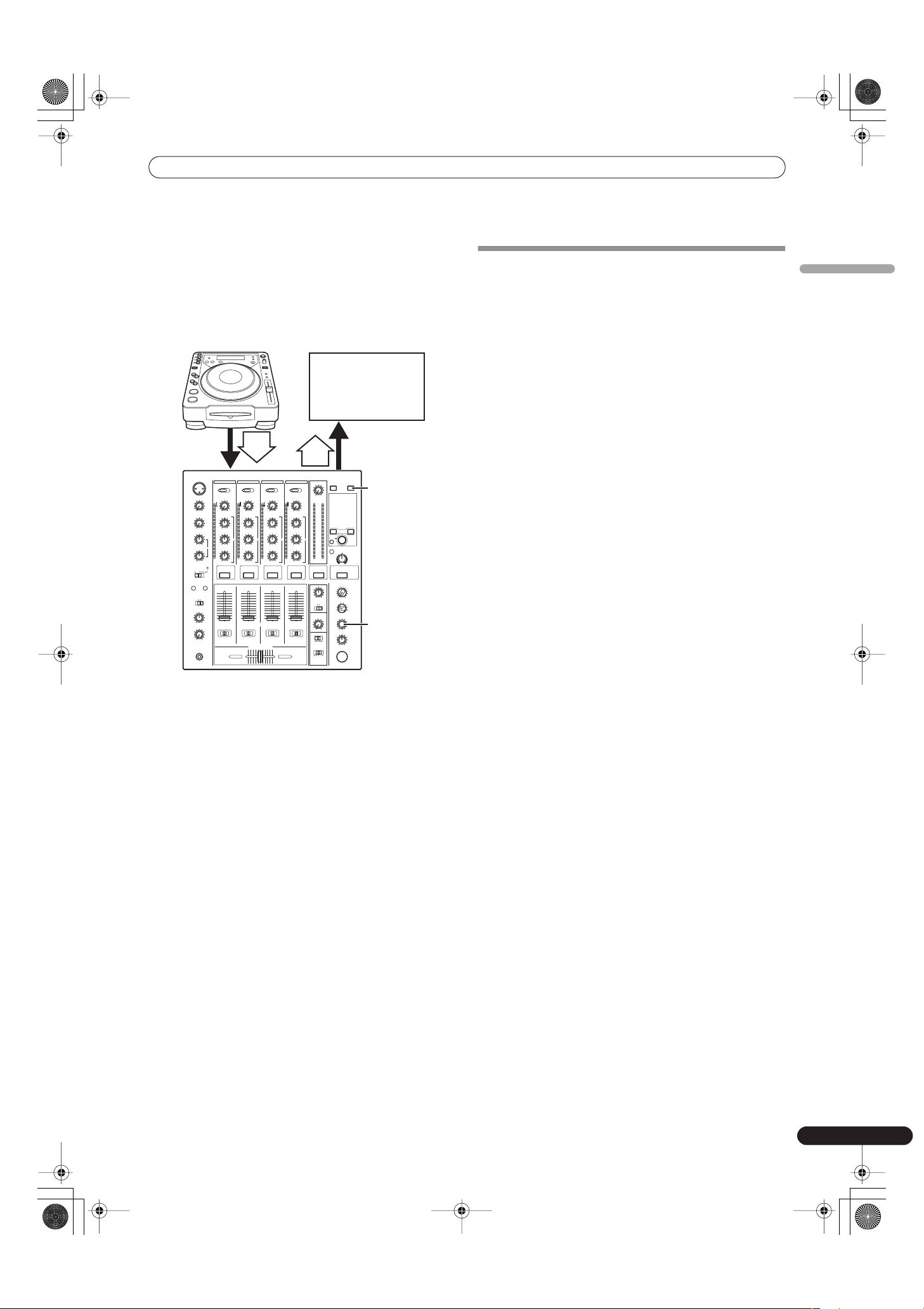
SYNCHRONIZING AUDIO SIGNALS TO
EXTERNAL SEQUENCER, OR USING
DJM-700-S/DJM-700-K INFORMATION TO
OPERATE AN EXTERNAL SEQUENCER
1 Use a commercially available MIDI cable to connect the
DJM-700-S/DJM-700-K’s MIDI OUT connector to the MIDI
sequencer’s MIDI IN connector.
• Set the MIDI sequencer’s synch mode to “Slave”.
• MIDI sequencers that do not support MIDI timing clock
cannot be synchronized.
• Synch may not be achieved if the track’s BPM cannot be
detected and measured stably.
• BPM values set with the TAP mode can also be used to
output the timing clock.
2 Press the MIDI START/STOP button.
• The MIDI timing clock output range is 40 to 250 BPM.
[MIDI Channel Setting]
The MIDI channel (1 to 16) can be set and stored in memory.
1 While holding the MIDI START/STOP button depressed, set
the power switch to ON.
• The display will show [
CH SET
] and the unit will enter the
MIDI setting mode.
2 Rotate the TIME dial to select the MIDI channel.
3 Press the MIDI START/STOP button.
• Records MIDI channel. During recording of channel, [
SAVE
]
indicator flashes.
• When recording of channel is completed, [
END
] is
displayed.
4 Set power to OFF.
DJ CD Player
MIDI sequencer
Audio
MIDI START
/STOP
TIME
MIDI OUT
DJM-700-S/DJM-700-K
OUT
BPM
=120
BPM
=120
IN
IN
01_DJM-700_En.book 21 ページ 2007年7月10日 火曜日 午後8時41分
MIDI SETTINGS
22
En
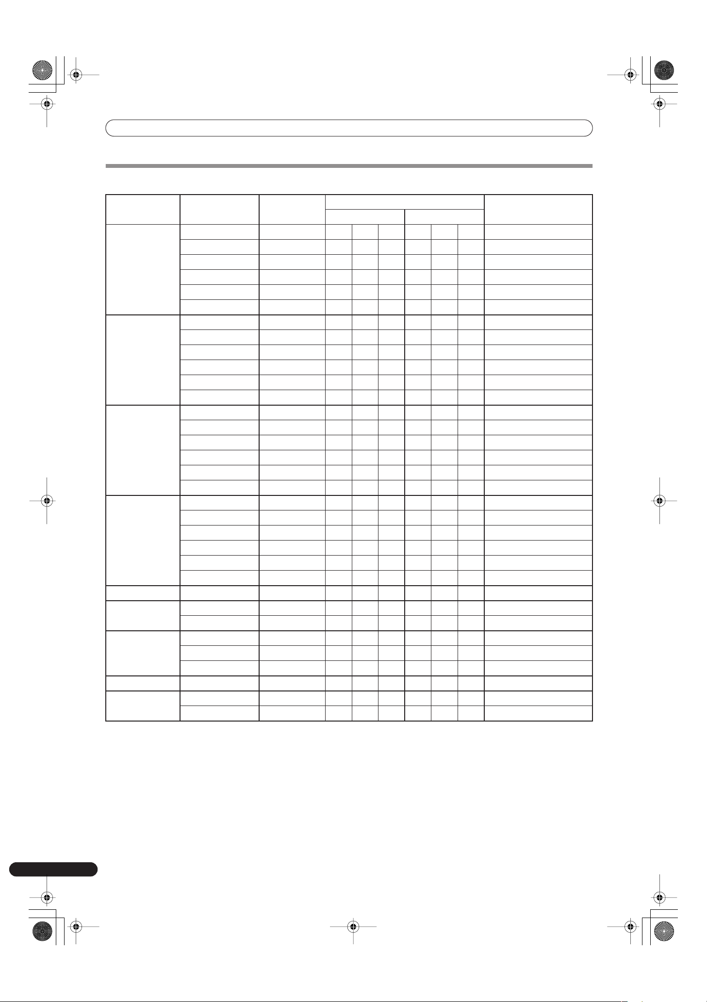
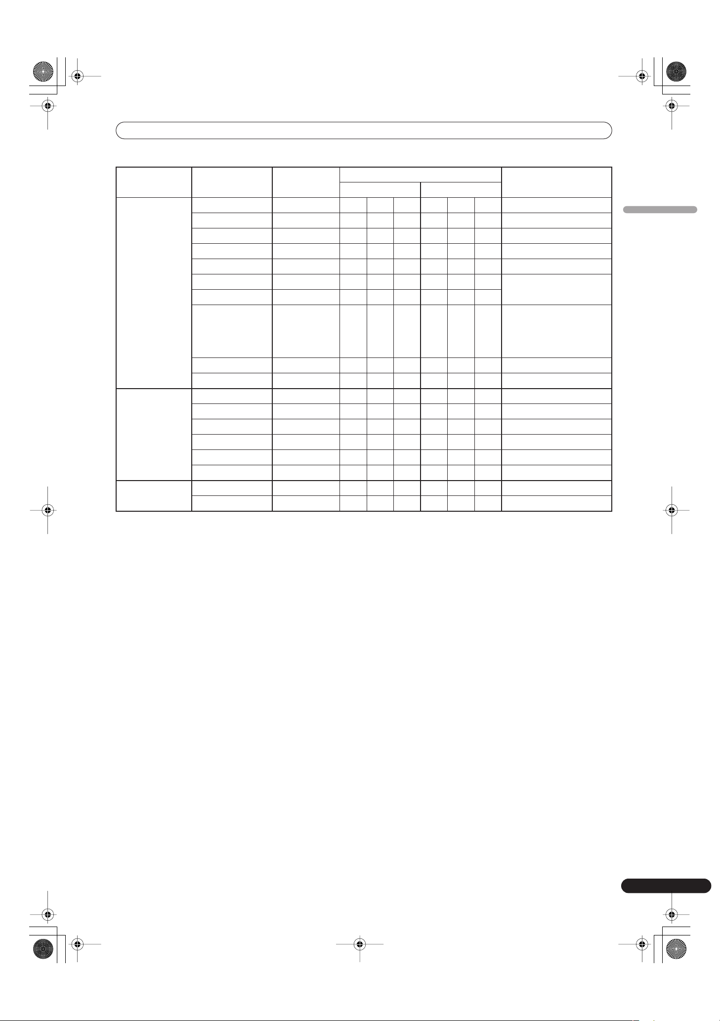
MIDI MESSAGES
Category Switch Name Switch Type
MIDI Message
Commnets
MSB LSB
CH1 HI VR Bn 02 dd 0 to 127
MID VR Bn 03 dd 0 to 127
LOW VR Bn 04 dd 0 to 127
CUE BUTTON Bn 46 dd OFF=0, ON=127
FADER VR Bn 11 dd 0 to 127
CF ASSIGN SW Bn 41 dd 0, 64, 127
CH2 HI VR Bn 07 dd 0 to 127
MID VR Bn 08 dd 0 to 127
LOW VR Bn 09 dd 0 to 127
CUE BUTTON Bn 47 dd OFF=0, ON=127
FADER VR Bn 12 dd 0 to 127
CF ASSIGN SW Bn 42 dd 0, 64, 127
CH3 HI VR Bn 0E dd 0 to 127
MID VR Bn 0F dd 0 to 127
LOW VR Bn 15 dd 0 to 127
CUE BUTTON Bn 48 dd OFF=0, ON=127
FADER VR Bn 13 dd 0 to 127
CF ASSIGN SW Bn 43 dd 0, 64, 127
CH4 HI VR Bn 51 dd 0 to 127
MID VR Bn 5C dd 0 to 127
LOW VR Bn 52 dd 0 to 127
CUE BUTTON Bn 49 dd OFF=0, ON=127
FADER VR Bn 14 dd 0 to 127
CF ASSIGN SW Bn 44 dd 0, 64, 127
CROSS FADER CROSS FADER VR Bn 0B dd 0 to 127
FADER CURVE CH CURVE SW Bn 5E dd 0, 127
CROSS CURVE SW Bn 5F dd 0, 64, 127
MASTER MASTER LEVEL VR Bn 18 dd 0 to 127
BALANCE VR Bn 17 dd 0 to 127
CUE BUTTON Bn 4A dd OFF=0, ON=127
BOOTH MONITOR VR Bn 19 dd 0 to 127
FILTER FILTER BUTTON Bn 54 dd OFF=0, ON=127
FREQUENCY VR Bn 05 dd 0 to 127
01_DJM-700_En.book 22 ページ 2007年7月10日 火曜日 午後8時41分
MIDI SETTINGS
23
En
English
EFFECT BEAT LEFT BUTTON Bn 4C dd OFF=0, ON=127
BEAT RIGHT BUTTON Bn 4D dd OFF=0, ON=127
AUTO/TAP BUTTON Bn 45 dd OFF=0, ON=127
TAP BUTTON Bn 4E dd OFF=0, ON=127
CUE BUTTON Bn 4B dd OFF=0, ON=127
EFFECT KIND SW Cn pc
See “PROGRAM CHANGE”
below.
CH SELECT SW Cn pc
TIME SW Bn 0D MSB Bn 2D LSB PARAMETER 1 value;
FLANGER, PHASER, FILTER,
CRUSH changed to 1/2
value; minus values are
converted to positive.
LEVEL/DEPTH VR Bn 5B dd 0 to 127
EFFECT ON/OFF BUTTON Bn 40 dd OFF=0, ON=127
MIC HI VR Bn 1E dd 0 to 127
LOW VR Bn 1F dd 0 to 127
(FADER START) FADER START 1 BUTTON Bn 58 dd OFF=0, ON=127
FADER START 2 BUTTON Bn 59 dd OFF=0, ON=127
(HEAD PHONES) MIXING VR Bn 1B dd 0 to 127
LEVEL VR Bn 1A dd 0 to 127
MIDI START BUTTON FA
STOP BUTTON FC
Category Switch Name Switch Type
MIDI Message
Commnets
MSB LSB
01_DJM-700_En.book 23 ページ 2007年7月10日 火曜日 午後8時41分
MIDI SETTINGS
24
En
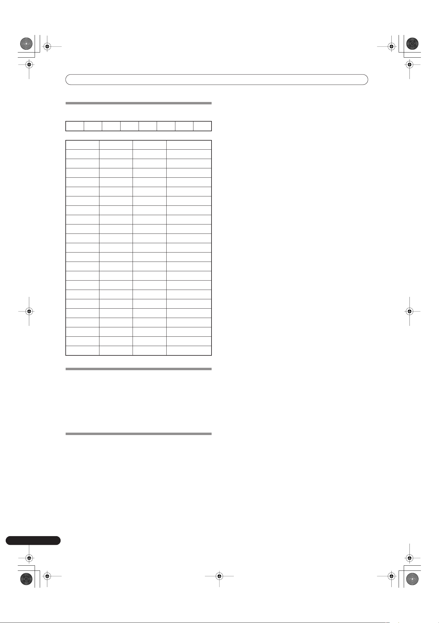
PROGRAM CHANGE
MSB LSB
• EFFECT SEL BEAT
SNAPSHOT
Once the DJM-700-S/DJM-700-K is setup with parameters for a
given purpose, that set of parameters can be recorded as a
snapshot. When snapshot of the current status is recorded, all
messages for control change and program change are
transmitted. Hold the
MIDI START/STOP
button depressed to send
the snapshot.
MIDI ON/OFF
Use the
MIDI ON/OFF
button to control whether the MIDI control
signal is generated. The default condition is MIDI OFF. Even when
MIDI OFF is selected, however, timing clock and snap shot
functions are supported.
00EFFSEL2 EFFSEL1 EFFSEL0 EFFCH2 EFFCH1 EFFCH0
EFFSEL2 EFFSEL1 EFFSEL0
001DELAY
010ECHO
100TRANS
110FILTER
101FLANGER
111PHASER
011REVERB
———ROBOT
———CRUSH
———ROLL
———REV ROLL
———UP ROLL
———DWNROLL
———SND/RTN
0011
0102
0113
1004
101MIC
110CF.A
111CF.B
———MASTER
01_DJM-700_En.book 24 ページ 2007年7月10日 火曜日 午後8時41分
TROUBLESHOOTING
25
En
English
TROUBLESHOOTING
Incorrect operations are often mistaken for trouble and malfunctions. If you think there is something wrong with this component, check
the points below. Sometimes the trouble may originate from another component. Thus, also check the other electrical appliances also in
use.
If the trouble cannot be rectified even after checking the following items, contact your dealer or nearest PIONEER service center.
Static electricity or other external interference may cause the unit to malfunction. To restore normal operation, turn the power off and then
on again.
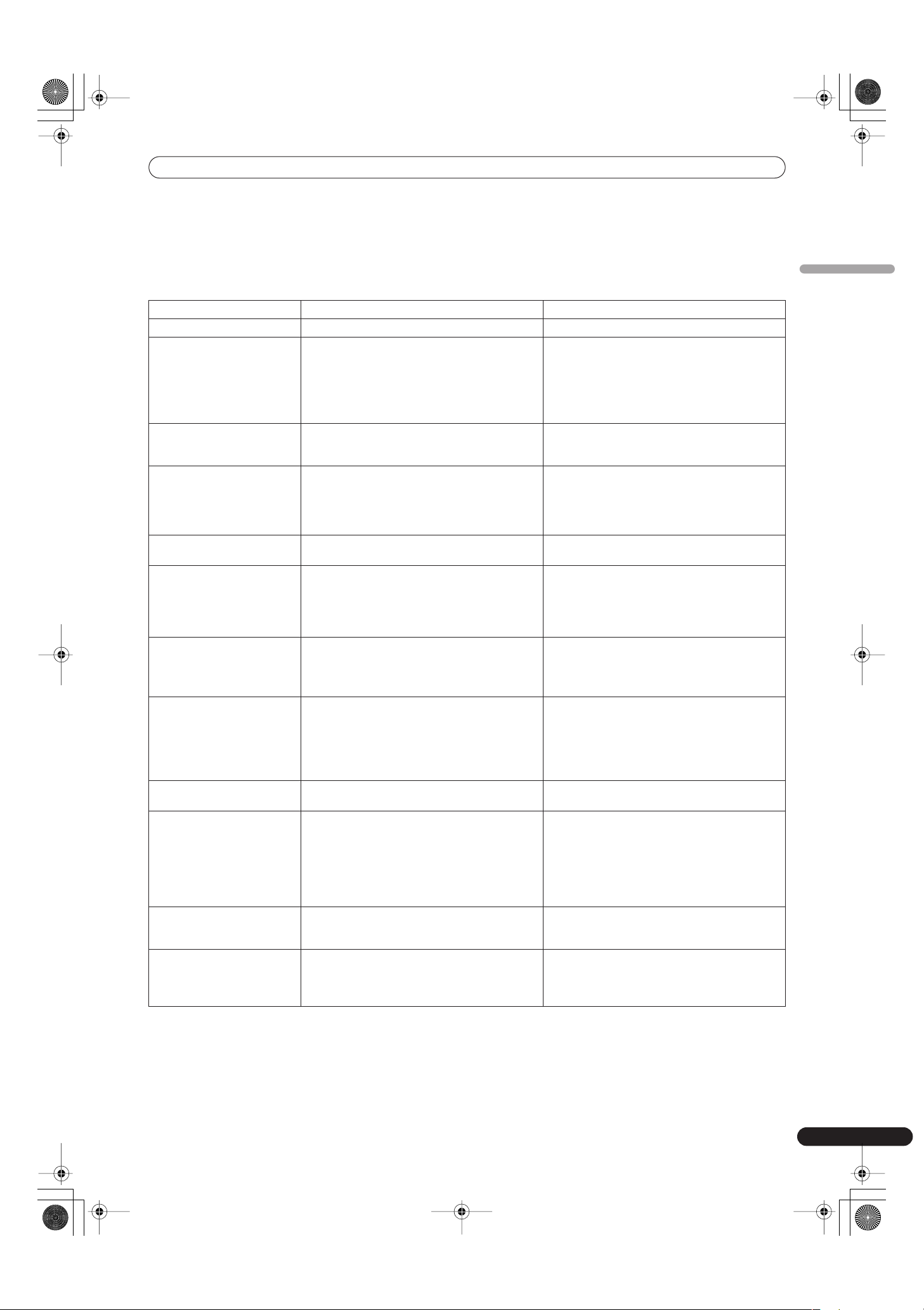
Symptom Possible Cause Remedy
No power • The power cord has not been connected. • Connect to power outlet.
No sound, or sound volume is
too low.
• Input selector is set incorrectly.
• Connection cables are connected incorrectly, or
connections are loose.
• Jacks or plugs are dirty.
• The rear panel master output attenuator switch
(
MASTER ATT
) is set to –6 dB, etc.
• Set input selector to playback component.
• Connect correctly.
• Clean soiled jacks/plugs before connecting.
• Adjust rear panel master attenuator switch
(
MASTER ATT
).
No digital output. • The digital output sampling frequency (fs) does
not match the specifications of the connected
component.
• Set rear panel sampling frequency selector to
match the specifications of the connected
component.
Sound is distorted. • Master output level is too high.
• Input level is too high.
• Adjust master output level (
MASTER LEVEL
)
dial or the rear panel master output attenuator
(
MASTER ATT
) switch.
• Adjust the
TRIM
dial so that the input level
approaches 0 dB on the channel level indicator.
Cross fader doesn’t work. •
CROSS FADER ASSIGN
switch setting ([
A
],
[
THRU
], [
B
]) is incorrect.
• Correctly set the
CROSS FADER ASSIGN
switch
for the desired channel.
Can’t perform fader start with
CD player.
• The
FADER START
button is set to OFF.
• Rear panel
CONTROL
jack is not connected to
CD player.
• Only the rear panel
CONTROL
jack is connected
to the CD player.
• Set the
FADER START
button to ON.
• Use a control cable to connect the
CONTROL
jacks of mixer and CD player.
• Connect both the
CONTROL
jacks and analog
input connectors.
Effects don’t work. • Effect channel selecter setting is incorrect.
• Effect parameter 2 adjust dial (
LEVEL/DEPTH
) is
set to [
MIN
].
• Correctly select the channel on which you wish
to apply effects.
• Adjust the effect parameter 2 adjust dial
(
LEVEL/DEPTH
).
External effector doesn’t work. • Effect selecter is not set to [
SND/RTN
].
• Effector is not connected to rear panel
SEND/
RETURN
connector.
• Effect channel selector is set to incorrectly.
• Set effect selector to [
SND/RTN
].
• Connect effector to the rear panel
SEND/
RETURN
connectors.
• Use the effect channel selector to select the
audio source to which you wish to apply the
effects.
Sound from external effector is
distorted.
• Input level from external effector is set too high. • Lower the output level of the external effector.
BPM can’t be measured.
Measured BPM value is
incorrect.
• Input level is too high, or too low.
• BPM may not be correctly measurable with
some tracks.
• Adjust the
TRIM
dial so that the input level
approaches 0 dB in the channel level indicator.
• Adjust other channels as well so that the input
levels approach 0 dB in the channel level
indicator.
• Strike the
TAP
button to set BPM manually.
The measured BPM value is
different from the value
published with the CD.
• Some differences may occur due to differences
in BPM detection methods.
• No remedy is necessary.
MIDI sequencer can’t be
synchronized.
• MIDI sequencer’s synch mode is not set to
“slave”.
• MIDI sequencer is not supported type.
• Set MIDI sequencer’s sync mode to “slave”.
• MIDI sequencers that do not support MIDI
timing clock cannot be synchronized.
01_DJM-700_En.book 25 ページ 2007年7月10日 火曜日 午後8時41分
SPECIFICATIONS
26
En
SPECIFICATIONS
1 General
Power source . . . . . . . . . . . . . . . . . . AC 220 V to 240 V, 50 Hz/60 Hz
Power consumption. . . . . . . . . . . . . . . . . . . . . . . . . . . . . . . . . . . 33 W
Operating temperature . . . . . . . . . . . . . . . . . . . . . +5 °C to +35 °C
Operating humidity . . . . . . . . . 5 % to 85 % (without condensation)
Weight . . . . . . . . . . . . . . . . . . . . . . . . . . . . . . . . . . . . . . . . . . . . . 6.6 kg
Maximum dimensions
. . . . . . . . . . . . . . . . . . . 320 mm (W) x 378.4 mm (D) x 107.9 mm (H)
2 Audio section
Sampling rate . . . . . . . . . . . . . . . . . . . . . . . . . . . . . . . . . . . . . . .96 kHz
A/D, D/A converter . . . . . . . . . . . . . . . . . . . . . . . . . . . . . . . . . . . 24 bits
Frequency response
LINE . . . . . . . . . . . . . . . . . . . . . . . . . . . . . . . . . . . . . 20 Hz to 20 kHz
MIC . . . . . . . . . . . . . . . . . . . . . . . . . . . . . . . . . . . . . 20 Hz to 20 kHz
PHONO . . . . . . . . . . . . . . . . . . . . . . . . . . . . 20 Hz to 20 kHz (RIAA)
S/N ratio (at rated output)
LINE . . . . . . . . . . . . . . . . . . . . . . . . . . . . . . . . . . . . . . . . . . . . .104 dB
PHONO . . . . . . . . . . . . . . . . . . . . . . . . . . . . . . . . . . . . . . . . . . .94 dB
MIC . . . . . . . . . . . . . . . . . . . . . . . . . . . . . . . . . . . . . . . . . . . . . .82 dB
Distortion (LINE-MASTER 1) . . . . . . . . . . . . . . . . . . . . . . . . . . 0.005 %
Standard input level/Input impedance
PHONO 2 to 4 . . . . . . . . . . . . . . . . . . . . . . . . . . . . . . –52 dBu/47 k
Ω
MIC 1, MIC 2 . . . . . . . . . . . . . . . . . . . . . . . . . . . . . . –52 dBu/22 k
Ω
LINE, LINE/CD 1 to 4 . . . . . . . . . . . . . . . . . . . . . . . .–12 dBu/22 k
Ω
RETURN . . . . . . . . . . . . . . . . . . . . . . . . . . . . . . . . . . –12 dBu/47 k
Ω
Standard output level/Load impedance/Output impedance
MASTER 1 . . . . . . . . . . . . . . . . . . . . . . .+8 dBu/10 k
Ω
/22
Ω
or less
MASTER 2 . . . . . . . . . . . . . . . . . . . . . . . . . . . . .+2 dBu/10 k
Ω
/10
Ω
REC . . . . . . . . . . . . . . . . . . . . . . . . . . . . . . . . . . –8 dBu/10 k
Ω
/10
Ω
BOOTH . . . . . . . . . . . . . . . . . . . . . . . . . . . . . . .+2 dBu/10 k
Ω
/22
Ω
SEND. . . . . . . . . . . . . . . . . . . . . . . . . . . . . . . . –12 dBu/10 k
Ω
/1 k
Ω
PHONES . . . . . . . . . . . . . . . . . . . . . . . +8.5 dBu/32
Ω
/22
Ω
or less
Rated output level/Load impedance
MASTER 1 . . . . . . . . . . . . . . . . . . . . . . . . . . . . . . . . +25 dBu/10 k
Ω
MASTER 2 . . . . . . . . . . . . . . . . . . . . . . . . . . . . . . . . +20 dBu/10 k
Ω
Crosstalk (LINE) . . . . . . . . . . . . . . . . . . . . . . . . . . . . . . . . . . . . . .82 dB
Channel equalizer response
HI . . . . . . . . . . . . . . . . . . . . . . . . . . . . . . –26 dB to +6 dB (13 kHz)
MID . . . . . . . . . . . . . . . . . . . . . . . . . . . . . . –26 dB to +6 dB (1 kHz)
LOW. . . . . . . . . . . . . . . . . . . . . . . . . . . . . . –26 dB to +6 dB (70 Hz)
Microphone equalizer response
HI . . . . . . . . . . . . . . . . . . . . . . . . . . . . . . –12 dB to +12 dB (10 kHz)
LOW. . . . . . . . . . . . . . . . . . . . . . . . . . . . –12 dB to +12 dB (100 Hz)
3 Input/output connector systems
PHONO input connectors
RCA pin jacks . . . . . . . . . . . . . . . . . . . . . . . . . . . . . . . . . . . . . . . . . 3
CD input connectors
RCA pin jacks . . . . . . . . . . . . . . . . . . . . . . . . . . . . . . . . . . . . . . . . . 2
LINE input connectors
RCA pin jacks . . . . . . . . . . . . . . . . . . . . . . . . . . . . . . . . . . . . . . . . . 3
MIC input connectors
XLR connector. . . . . . . . . . . . . . . . . . . . . . . . . . . . . . . . . . . . . . . . . 1
Phone jack (Ø6.3 mm) . . . . . . . . . . . . . . . . . . . . . . . . . . . . . . . . . . 1
RETURN input connectors
Phone jacks (Ø6.3 mm) . . . . . . . . . . . . . . . . . . . . . . . . . . . . . . . . . 1
MASTER output connectors
XLR connectors. . . . . . . . . . . . . . . . . . . . . . . . . . . . . . . . . . . . . . . . 1
RCA pin jacks . . . . . . . . . . . . . . . . . . . . . . . . . . . . . . . . . . . . . . . . . 1
BOOTH output connectors
RCA pin jacks . . . . . . . . . . . . . . . . . . . . . . . . . . . . . . . . . . . . . . . . . 1
REC output connectors
RCA pin jacks . . . . . . . . . . . . . . . . . . . . . . . . . . . . . . . . . . . . . . . . . 1
SEND output connectors
Phone jacks (Ø6.3 mm) . . . . . . . . . . . . . . . . . . . . . . . . . . . . . . . . . 1
DIGITAL coaxial output connector
RCA pin jack . . . . . . . . . . . . . . . . . . . . . . . . . . . . . . . . . . . . . . . . . . 1
MIDI OUT connector
5P DIN . . . . . . . . . . . . . . . . . . . . . . . . . . . . . . . . . . . . . . . . . . . . . . . 1
PHONES output connector
Stereo phone jack (Ø6.3 mm) . . . . . . . . . . . . . . . . . . . . . . . . . . . . 1
CONTROL connector
Mini phone jacks (Ø3.5 mm) . . . . . . . . . . . . . . . . . . . . . . . . . . . . . 2
4 Accessories
Operating Instructions . . . . . . . . . . . . . . . . . . . . . . . . . . . . . . . . . . . . 1
Specifications and appearance are subject to change without
notice.
01_DJM-700_En.book 26 ページ 2007年7月10日 火曜日 午後8時41分
27
En
English
01_DJM-700_En.book 27 ページ 2007年7月10日 火曜日 午後8時41分

Ce produit est conforme à la directive relative à la
basse tension 2006/95/CE et à la directive relative à
la compatibilité électromagnétique 2004/108/CE.
D3-4-2-1-9a_A_Fr
Ce point d’exclamation, placé dans un
triangle équilatéral, a pour but d’attirer
l’attention de l’utilisateur sur la présence,
dans les documents qui accompagnent
l’appareil, d’explications importantes du
point de vue de l’exploitation ou de
l’entretien.
Ce symbole de l’éclair, placé dans un
triangle équilatéral, a pour but d’attirer
l’attention de l’utilisateur sur la présence, à
l’intérieur du coffret de l’appareil, de
“tensions dangereuses” non isolées d’une
grandeur suffisante pour représenter un
risque d’électrocution pour les êtres
humains.
IMPORTANT
ATT ENTION:
POUR ÉVITER TOUT RISQUE
D’ÉLECTROCUTION, NE PAS ENLEVER LE
COUVERCLE (NI LE PANNEAU ARRIÈRE).
AUCUNE PIÈCE RÉPARABLE PAR
L’UTILISATEUR NE SE TROUVE À
L’ I N TÉRIEUR. CONFIER TOUT ENTRETIEN À
UN PERSONNEL QUALIFIÉ UNIQUEMENT.
ATTENTION
DANGER D´ELECTROCUTION
NE PAS OUVRIR
D3-4-2-1-1_Fr
AVERTISSEMENT
Cet appareil n’est pas étanche. Pour éviter les
risques d’incendie et de décharge électrique, ne
placez près de lui un récipient rempli d’eau, tel
qu’un vase ou un pot de fleurs, et ne l’exposez pas
à des gouttes d’eau, des éclaboussures, de la pluie
ou de l’humidité.
D3-4-2-1-3_A_Fr
AVERTISSEMENT
Pour éviter les risques d’incendie, ne placez aucune
flamme nue (telle qu’une bougie allumée) sur
l’appareil.
PRÉCAUTION DE VENTILATION
Lors de l’installation de l’appareil, veillez à laisser
un espace suffisant autour de ses parois de manière
à améliorer la dissipation de chaleur (au moins 5 cm
àl’arrière et 3 cm de chaque côté).
AVERTISSEMENT
Les fentes et ouvertures du coffret sont prévues
pour la ventilation, pour assurer un fonctionnement
stable de l’appareil et pour éviter sa surchauffe.
Pour éviter les risques d’incendie, ne bouchez
jamais les ouvertures et ne les recouvrez pas
d’objets, tels que journaux, nappes ou rideaux, et
n’utilisez pas l’appareil posé sur un tapis épais ou
un lit.
Milieu de fonctionnement
Température et humidité du milieu de fonctionnement :
De +5 à +35ºC (de +41 à +95ºF); Humidité relative
inférieure à 85% (orifices de ventilation non obstrués)
N’installez pas l’appareil dans un endroit mal ventilé ou
un lieu soumis à une forte humidité ou en plein soleil
(ou à une forte lumière artificielle).
D3-4-2-1-7c_A_Fr
K058_A_Fr
Si vous souhaitez vous débarrasser de cet appareil, ne le mettez pas à la poubelle avec vos ordures ménagères. Il existe un système
de collecte séparé pour les appareils électroniques usagés, qui doivent être récupérés, traités et recyclés conformément à la
législation.
Les habitants des états membres de l’UE, de Suisse et de Norvège peuvent retourner gratuitement leurs appareils électroniques usagés aux
centres de collecte agréés ou à un détaillant (si vous rachetez un appareil similaire neuf).
Dans les pays qui ne sont pas mentionnés ci-dessus, veuillez contacter les autorités locales pour savoir comment vous pouvez vous débarrasser
de vos appareils.
Vous garantirez ainsi que les appareils dont vous vous débarrassez sont correctement récupérés, traités et recyclés et préviendrez de cette façon
les impacts néfastes possibles sur l’environnement et la santé humaine.
Si la fiche d’alimentation secteur de cet appareil ne
convient pas à la prise secteur à utiliser, la fiche doit
être remplacée par une appropriée.
Ce remplacement et la fixation d’une fiche secteur
sur le cordon d’alimentation de cet appareil doivent
être effectués par un personnel de service qualifié.
En cas de branchement sur une prise secteur, la
fiche de coupure peut provoquer une sérieuse
décharge électrique. Assurez-vous qu’elle est
éliminée correctement après sa dépose.
L’ a p pareil doit être déconnecté en débranchant sa
fiche secteur au niveau de la prise murale si vous
prévoyez une période prolongée de non utilisation
(par exemple avant un départ en vacances).
ATT ENTION
L’ i n terrupteur POWER de cet appareil ne coupe pas
complètement celui-ci de sa prise secteur. Comme
le cordon d’alimentation fait office de dispositif de
déconnexion du secteur, il devra être débranché au
niveau de la prise secteur pour que l’appareil soit
complètement hors tension. Par conséquent, veillez
àinstaller l’appareil de telle manière que son cordon
d’alimentation puisse être facilement débranché de
la prise secteur en cas d’accident. Pour éviter tout
risque d’incendie, le cordon d’alimentation sera
débranché au niveau de la prise secteur si vous
prévoyez une période prolongée de non utilisation
(par exemple avant un départ en vacances).
NOTE IMPORTANTE SUR LE CABLE
D’ALIMENTATION
Tenir le câble d’alimentation par la fiche. Ne pas
débrancher la prise en tirant sur le câble et ne pas
toucher le câble avec les mains mouillées. Cela risque
de provoquer un court-circuit ou un choc électrique. Ne
pas poser l’appareil ou un meuble sur le câble. Ne pas
pincer le câble. Ne pas faire de noeud avec le câble ou
l’attacher à d’autres câbles. Les câbles d’alimentation
doivent être posés de façon à ne pas être écrasés. Un
câble abîmé peut provoquer un risque d’incendie ou un
choc électrique. Vérifier le câble d’alimentation de
temps en temps. Contacter le service après-vente
PIONEER le plus proche ou le revendeur pour un
remplacement.
Nous vous remercions pour cet achat d’un produit Pioneer.
Nous vous demandons de lire soigneusement ce mode d’emploi; vous serez ainsi à même de faire fonctionner l’appareil
correctement. Après avoir bien lu le mode d’emploi, le ranger dans un endroit sûr pour pouvoir s’y référer ultérieurement.
Dans certains pays ou certaines régions, la forme de la fiche d’alimentation et de la prise d’alimentation peut différer de celle qui
figure sur les schémas, mais les branchements et le fonctionnement de l’appareil restent les mêmes.
Lorsque vous utilisez ce produit, respectez les
instructions inscrites sur le fond à propos de la
tension nominale et d’autres paramètres.
D3-4-2-2-4_Fr
AVERTISSEMENT
La tension de l’alimentation électrique disponible
varie selon le pays ou la région. Assurez-vous que
la tension du secteur de la région où l’appareil sera
utilisé correspond à la tension requise (par ex. 230
Vou120 V), indiquée sur le panneau inférieur.
D3-4-2-1-4_A_Fr MOD
Avant de brancher l’appareil pour la première, lisez
attentivement la section suivante.
02_DJM-700_Fr.book 2 ページ 2007年7月10日 火曜日 午後8時42分

Table des matières
3
Fr
Français
Table des matières
VÉRIFICATION DES ACCESSOIRES ..............................4
AVERTISSEMENTS CONCERNANT L’USAGE................4
Emplacement................................................................................. 4
Nettoyer l’appareil ......................................................................... 4
CARACTÉRISTIQUES ....................................................4
BRANCHEMENTS .........................................................5
PANNEAU DE CONNEXION......................................................... 5
BRANCHEMENT DES ENTRÉES.................................................. 6
BRANCHEMENT D’EFFECTEURS EXTERNES, CONNECTEURS
DE SORTIE...................................................................................... 7
À PROPOS DES CONNECTEURS MIDI....................................... 8
BRANCHEMENT D’UN MICROPHONE ET D’UN CASQUE....... 8
BRANCHEMENT DU CORDON D’ALIMENTATION.................... 8
NOMS ET FONCTIONS DES ORGANES.........................9
UTILISATION DU MIXEUR ..........................................13
FONCTION DE DÉPART EN FONDU.......................................... 14
FONCTIONS DES EFFETS............................................16
PRODUCTION D’EFFETS DE BATTEMENT................................ 18
UTILISATION DU FILTRE MANUEL ............................................19
UTILISATION DU FILTRE DE FRÉQUENCE D’EFFET ................ 19
PARAMÈTRES DES EFFETS ....................................................... 20
RÉGLAGES MIDI ........................................................21
SYNCHRONISATION DES SIGNAUX AUDIO A UN
SÉQUENCEUR EXTERNE, OU UTILISATION DES
INFORMATIONS DU DJM-700-S/DJM-700-K POUR
CONTRÔLER UN SÉQUENCEUR EXTERNE.............................. 21
MESSAGES MIDI ......................................................................... 22
CHANGEMENT DE PROGRAMME............................................. 24
SNAPSHOT (INSTANTANÉ)........................................................ 24
MIDI ON/OFF................................................................................ 24
GUIDE DE DÉPANNAGE.............................................25
FICHE TECHNIQUE......................................................26
02_DJM-700_Fr.book 3 ページ 2007年7月10日 火曜日 午後8時42分

4
Fr
VÉRIFICATION DES
ACCESSOIRES
Mode d’emploi . . . . . . . . . . . . . . . . . . . . . . . . . . . . . . . . . . . . . . . . . . .1
AVERTISSEMENTS
CONCERNANT L’USAGE
Emplacement
Installez l’appareil dans un endroit bien aéré, où il ne sera
pas exposé à de hautes températures ou à l’humidité.
• N’installez pas l’appareil dans un endroit exposé aux rayons
de soleil directs, ni à proximité de poêles ou de radiateurs. Le
boîtier et les parties internes peuvent être endommagés par
de fortes chaleurs. L’installation de l’appareil dans un
environnement humide ou poussiéreux peut entraîner un
dysfonctionnement ou un accident. (Evitez d’installer
l’appareil à proximité de cuisinières etc., où il pourrait être
exposé à des fumées grasses, à des vapeurs ou à la chaleur.)
• Si l‘appareil est utilisé dans une mallette ou dans une cabine
de DJ, éloignez-le des parois ou d‘autres appareils afin de
favoriser l‘évacuation de la chaleur.
Nettoyer l’appareil
• Utilisez un chiffon à poussière pour enlever la poussière et
les saletés.
• Si les surfaces sont très sales, nettoyez avec un chiffon doux
trempé dans un détergent neutre, dilué dans cinq ou six fois
plus d’eau, essorez bien et repassez avec un chiffon sec.
N’utilisez pas de cire à meubles ou de détachants.
• N’utilisez jamais de diluants, de benzène, d’insecticides ou
d’autres produits chimiques sur ou à proximité de l’appareil,
car ceux-ci abîment les surfaces.
CARACTÉRISTIQUES
Conçu en vue d’une haute qualité sonore
Transmis par des circuits les plus courts possibles, les signaux
analogiques sont convertis en format numérique à un taux
d’échantillonnage de 96 kHz via un convertisseur A/N 24 bits de
haute qualité. Il en résulte que les signaux sont passés à l’étage de
mixage numérique dans le meilleur état possible. Le mixage est
exécuté par un processeur de signal numérique (DSP) à 32 bits, ce
qui élimine complètement toute perte en fidélité, tandis qu’un
niveau idéal de filtrage est introduit afin de fournir un son optimal
pour la lecture DJ.
Ces fonctions sont regroupées dans un coffret très rigide avec la
section alimentation à forte sortie et d’autres atouts qui
perpétuent les performances de haute fidélité du DJM-1000, ce qui
vous garantit le nec plus ultra en sonorités claires et puissantes.
Filtre manuel
Cet appareil comporte un Effecteur Manuel en vue d’un réglage
plus intuitif des effets, ce qui élargit la plage potentiel du jeu en DJ.
De plus, par combinaison de cet atout avec les “effets de
battement”, une gamme d’effets encore plus large peut être
produite, ce qui offre une extraodinaire variété de Remix et de DJ
play.
Effets de battement
Très populaires déjà sur le DJM-600, les “effets de battement” ont
été maintenus. Ils peuvent être appliqués en liaison avec le
compte BPM (Battements par minute), ce qui autorise la
production d’une grande variété de sons.
L’appareil est doté d’une large gamme d’effets spéciaux,
notamment delay, echo, trans, filter, flange, phaser, reverb, robot,
crush, roll, reverse roll, uproll et downroll.
L’appareil dispose aussi d’un “filtre de fréquence d’effet”. Il permet
à l’utilisateur de limiter les bandes de fréquence seront sujettes
aux effets et celles qui ne le seront pas. Ceci rehausse le degré
d’expression audio en comparaison des effecteurs traditionnels
qui sont appliqués à toute la gamme des fréquences.
Digital OUT
Les connecteurs de sortie numérique prennent en compte les taux
d’échantillonnage de 96 kHz/24 bits et le format 48 kHz/24 bits.
Ceci rend l’appareil encore plus pratique pour couper des pistes
de studio et à d’autres occasions lorsqu’une haute fidélité sonore
est requise. (Seul PCM linéaire est pris en compte.)
MIDI OUT
Pratiquement toutes les informations provenant des bagues et
commandes du DJM-700-S/DJM-700-K peuvent être fournies en
format de signal MIDI, ce qui permet de contrôler via les signaux
MIDI un composant, acceptant le contrôle MIDI.
Autres fonctions
• Un câble de commande peut être utilisé pour raccorder cet
appareil à un lecteur DJ CD de Pioneer, ce qui permet alors de
synchroniser la lecture avec le fonctionnement du fondu
(“Lecture à départ en fondu”).
• Incorporation d’un “Égaliseur 3 bandes”, permettant une
commande de niveau sur une plage de +6 dB à –26 dB pour
chaque bande passante.
• Fonction “Affectation de fondu croisé”, autorisant une
affectation plus souple de l’entrée de chaque canal à un fondu
croisé.
• Incorporation d’une fonction “Talk Over”, abaissant
automatiquement le volume de la piste, lors d’une entrée par
micro.
• Fonction “Ajustement de courbe de fondu”, permettant de
modifier les courbes de fondu croisé et de fondu de canal.
02_DJM-700_Fr.book 4 ページ 2007年7月10日 火曜日 午後8時42分
 Loading...